Embed Size (px)
Citation preview

APPLICATION OF QUALITY ASSURANCE SPECIFICATIONS
FOR ASPHALT CONCRETE MIXTURES
2016 Edition
Jointly Developed by The Louisiana Transportation and Research Center Technology Transfer and Training Section and the Louisiana Department of Transportation and Development
La Gov 10305 Application of Quality Assurance Specifications for Asphalt Concrete Mixtures

ii
iii
APPLICATION OF QUALITY ASSURANCE
SPECIFICATIONS
FOR
ASPHALT CONCRETE MIXTURES
Developed by
TECHNOLOGY TRANSFER AND TRAINING
LOUISIANA TRANSPORTATION AND RESEARCH CENTER
For
Louisiana Department of Transportation and Development
2016

iv
v
CREDITS This manual was developed by Chris Abadie, DOTD Materials Engineer Administrator, with the assistance of the technical review committee listed below. The manual was edited and prepared for publication by the LTRC Publications Department The Construction and Materials Sections of the Louisiana Department of Transportation and Development and the DOTD Chief Engineer have approved this manual for publication. Technical Advisory Committee 2016 Revised Edition
Mr. Chris Abadie
Materials Administrator
Dr. Sam Cooper, Jr. Director, LTRC
Mr. Paul “Marty” Farkas
DOTD Asphalt DCL – District 02
Mr. Frank Jones DOTD Asphalt DCL – District 05
Mr. Herbert Aaron
DOTD Asphalt DCL – District 08
Ms. Kim Martindale Garlington District 08 - Construction Coordinator
Mr. William King
LTRC Materials Research Engineer
Mr. Hector Santiago FHWA Engineering Coordinator
Mr. Scott Nelson
FHWA Asset Management/Pavement Engineer.
Mr. Michael Elliott LTRC District Training Liaison

vi
TABLE OF CONTENTS
vii
Topic Page
Policy ..................................................................................................................................... 1
Documentation ....................................................................................................................... 2
Definitions .............................................................................................................................. 3
Safety ..................................................................................................................................... 4
Environment Protection .......................................................................................................... 5
Contractor Notification ............................................................................................................ 5
Consequences of False Reporting or Misinformation ............................................................. 6
Quality Assurance .................................................................................................................. 7
Preliminary Source Approval of Materials ........................................................................... 7 Certification or Qualification of Technicians......................................................................... 7 Certification of Equipment and Processes ........................................................................... 8 Quality Control .................................................................................................................... 9 Inspection, Sampling, and Testing ...................................................................................... 9 Acceptance ....................................................................................................................... 10 Independent Assurance Program ...................................................................................... 10
Laboratory Accreditation and Certification ..................................................................... 11
Independent Assurance Programs .................................................................................... 13 Independent Assurance ................................................................................................. 13
System Independent Assurance Team .......................................................................... 13
Section 501 – Thin Asphalt Concrete Applications ............................................................... 15
Mix Design Steps and Approval ........................................................................................ 15 Material Procurement and Approval .............................................................................. 15
Aggregate...................................................................................................................... 15
Asphalt Cement ............................................................................................................. 16
Additives ....................................................................................................................... 16
Design of Asphalt Mixture, Job Mix Formula (JMF) ........................................................... 16 Determination of Gradation and Bulk Specific Gravity (Gsb) for Aggregates ................... 16
Blending Aggregates to Meet Specified Gradation ........................................................ 16
Design of Blended Aggregates for Travel Lane Wearing Courses ................................. 16
Dense, Coarse, and OGFC (Open Graded Friction Course) Mixtures ........................... 16
Additional Requirements for OGFC Mixtures ................................................................. 17
Trial Blends with Varying Asphalt Cement Contents (Except OGFC) ............................. 19
Selection of Optimum Asphalt Cement Content ............................................................. 19
Dust to Effective Asphalt Cement Ratio Evaluation ....................................................... 19
LWT, Loaded Wheel Test, (AASHTO T 324) ................................................................. 20
Approval of JMF proposal .............................................................................................. 20
Validation of JMF proposal ............................................................................................ 20
Final Approval of JMF ................................................................................................... 21
Definition of a Lot (Thin Asphalt Concrete mixtures) ......................................................... 21
TABLE OF CONTENTS
viii
Plant Quality Control ......................................................................................................... 21 Acceptance and Verification ............................................................................................. 22
Plant Acceptance .......................................................................................................... 22
Roadway Acceptance ................................................................................................... 23
Plant and Stockpile Verification ..................................................................................... 23
Measurement and Payment .............................................................................................. 24 Measurement ................................................................................................................ 24
Payment ....................................................................................................................... 24
Section 502 – Asphalt Concrete Mixtures............................................................................. 25
Mix Design Steps and Approval ........................................................................................ 25 Material Procurement and Approval .............................................................................. 25
Design of Asphalt Mixture, Job Mix Formula (JMF) ....................................................... 27
Determination of Gradation and Bulk Specific Gravity (Gsb) for Aggregates ................. 27
Bulk Specific Gravity (Gsb) ........................................................................................... 28
Consensus Aggregate Test Evaluations ....................................................................... 31
Coarse Aggregate Angularity (CAA) .............................................................................. 32
Fine Aggregate Angularity (FAA) .................................................................................. 32
Determination of RAP JMF Composite .......................................................................... 40
Trial Blends with Varying Asphalt Cement Contents ..................................................... 41
Selection of Optimum Asphalt Cement Content ............................................................ 47
Dust to Effective Asphalt Cement Ratio Evaluation ....................................................... 47
Moisture Susceptibility Analysis .................................................................................... 47
Loaded Wheel Tester, LWT Testing .............................................................................. 47
Validation of JMF Proposal ........................................................................................... 51
Final Approval of JMF ................................................................................................... 53
Definition of a Lot .............................................................................................................. 57 Roadway Lot ................................................................................................................. 57
Quality Control .................................................................................................................. 60 Plant Quality Control ..................................................................................................... 60
Plant Inspection ................................................................................................................ 65 Department Certified ADI Responsibilities for Plant Verification .................................... 65
Asphalt Cement Properties ........................................................................................... 66
Percent Anti-Strip .......................................................................................................... 67
PWL Calculation ........................................................................................................... 69
Roadway Quality Control .............................................................................................. 72
Roadway Inspection ......................................................................................................... 72 Inspection of Mixture on Roadway ................................................................................ 72
Adjustment Factors for Pay and Calculating Yield ............................................................ 75 Joint Construction ............................................................................................................. 80 Segregation ...................................................................................................................... 81 Coordination of Paving Operations ................................................................................... 83
TABLE OF CONTENTS
ix
Analysis of Test Data in the Acceptance Decision............................................................. 84 Plant Acceptance .......................................................................................................... 86
Roadway Acceptance .................................................................................................... 87
Mainline Lots: (92.0 min Density); 1000-ton Sublots; 5000-ton Lots .................................. 88 Minor Lots: (90.0 min Density) five 1000 Ton sublots ........................................................ 88 Measurement and Payment .............................................................................................. 93
Measurement ................................................................................................................ 93
Payment ........................................................................................................................ 93
Section 502.12 – Surface Tolerance ..................................................................................... 95
Profiler Certification ........................................................................................................... 95 Longitudinal Surface Tolerance Testing ............................................................................ 95
Pre-op Tests and Observations ..................................................................................... 96
Surface Tolerance Pay .................................................................................................. 97
Section 503 – Asphalt Concrete Equipment and Processes ................................................. 99
Plant Certification .............................................................................................................. 99 Initial Plant Certification ................................................................................................. 99
Random Conformance Inspections.............................................................................. 100
Re-Certification ........................................................................................................... 100
Revoked Certification .................................................................................................. 101
Plant Laboratory Equipment and Documentation......................................................... 101
Scales and Meters Certification ....................................................................................... 103 Roadway Equipment Approval ........................................................................................ 103 Inspection of Plant and Roadway Equipment .................................................................. 104
Plant Inspection ........................................................................................................... 104
Plant Equipment .......................................................................................................... 105
Inspection of Mixture at Plant ...................................................................................... 107
Haul Ticket .................................................................................................................. 108
Roadway Equipment ................................................................................................... 108
Section 504 – Asphalt Tack Coats ...................................................................................... 113
Application Rate Calculation ........................................................................................... 113
APPENDIX ......................................................................................................................... A-1
Example of core sampling determination ........................................................................ A-3 Quality Index Values for Estimating Percent Within Limits .............................................. A-5 Payment Adjustment for Mainline Pavement Density ...................................................... A-7 Generating and Using Random Numbers for Sampling Purposes ................................... A-9 Levels and Requirements for Asphalt Plant Qualified Tester and Certification .............. A-19 Asphalt Concrete Plant Certification DOTD 03-22-3075 (Rev. 10/15) .......................... A-21 Asphalt Concrete Plant Review ..................................................................................... A-29 Asphalt Concrete Roadway Equipment Review ............................................................ A-35 Superpave Asphalt Roadway Report ............................................................................ A-41 Suggested Tie-In Procedure ......................................................................................... A-43 Weight Certification Tag (example) ............................................................................... A-45

x
PART 1 – POLICY
1
Policy
This document supports the implementation of Part V, 2016 Standard Specifications for Roads and Bridges which incorporates several new policies: Contractor data used in the acceptance decision, planned verification, dispute resolution, and System Independent Assurance. The purpose of this manual is to supplement Part V of the 2016 LA Standard Specifications for Roads and Bridges, standardize policies and procedures, provide detail, explanation and examples, denote personnel requirements, and denote equipment and process requirements, all with the goal of facilitating uniform application of the specifications during the design, production and placement of asphalt concrete and associated work. Specifications – This manual is to be used in conjunction with the 2016 Edition of the Louisiana Standard Specifications for Roads and Bridges, or “Spec Book.” Relevant specifications are referenced throughout this manual. Specifications may be repeated in order to further detail or demonstrate how they are applied. All specifications, manuals, forms, and spreadsheets are subject to change. Therefore, it is imperative that contract documents for each project be reviewed for any specific change, Special Provision, Supplemental Specification, update, and/or addition. Manuals – Numerous manuals that are essential for performing DOTD asphalt-related work are listed below. The latest edition of each shall be available at the asphalt mixture production plant and at the district laboratory. Documents can be obtained from the Department at a published price through General Files at 225-379-1107. Many manuals are listed at http://wwwsp.dotd.la.gov , hereafter referred to as “website.” Documents are:
CONTRACT DOCUMENTS – the legally binding written agreement between the DOTD and the Contractor setting forth obligations for the performance of work for a specific project. (not on website) This may include Special Provisions or Supplemental Specifications.
2016 EDITION of the LOUISIANA STANDARD SPECIFICATIONS for ROADS and BRIDGES – (known as “Standard Specifications”) the terms and stipulations for providing materials, services and the finished constructed product.
MATERIALS SAMPLING MANUAL – (known as “MSM”) SAMPLING PLAN – The MSM establishes and standardizes sampling and acceptance requirements for Louisiana Department of Transportation and Development. The MSM determines what contract items are to be sampled and tested. Documentation, frequency, quantity and procedures for meeting project sampling requirements are detailed in the MSM. It can be found on the Materials Lab website:
TEST PROCEDURES MANUAL – all standardized DOTD test procedures, which are denoted, “DOTD TR-xxx.”
ENGINEERING DIRECTIVES AND STANDARDS MANUAL – (known as “EDSM”) establishes policies and procedures for DOTD Design, Construction, and Maintenance. An example is “haul truck certification.”

PART 1 – POLICY
2
APPROVED MATERIAL LIST (Formerly known as “QPL”) – a listing of materials which have been evaluated by DOTD. It lists companies that have demonstrated the ability to supply a product of acceptable quality. Project acceptance or verification testing is required of many products appearing on the Approved Materials list. Qualification Procedures for each category of Approved Materials is also listed here.
DOTD CONSTRUCTION MEMORANDA – The DOTD’s internal office documentation to explain various construction issues. (Only available to DOTD Employees on the Intranet. Go to Construction Home Page, to Construction Memos.)
CONSTRUCTION CONTRACT ADMINISTRATION MANUAL – Instructions for DOTD Project Engineers and their representatives which include procedures for change orders, estimates, diaries and field book entries.
AASHTO TEST PROCEDURES – a set of nationally recognized test procedures and specifications published by the American Association of State Highway and Transportation Officials. http://www.transportation.org/ and go to the bookstore. At the time of this writing, DOTD personnel have access through the LTRC “Library/Information Services.”
ASTM TEST PROCEDURES – a set of nationally recognized test procedures published by the American Society for Testing and Materials. www.astm.org, go to Standards, then search. DOTD personnel may contact the District Lab Engineer (DLE). At the time of this writing, DOTD personnel have access through the LTRC “Library/Information Services.”
ADMINISTRATIVE MANUAL for CONSTRUCTION TECHNICIAN TRAINING AND CERTIFICATION – certification and training requirements for performing construction inspection. http://www.ltrc.lsu.edu/certification.html
APPLICATION OF QUALITY ASSURANCE SPECIFICATIONS FOR ASPHALT CONCRETE MIXTURES – used in conjunction with and supplement Part V of the Louisiana Standard Specifications for Roads and Bridges for the design, production, and placement of Asphalt Concrete and associated work.
Documentation
Forms and Spreadsheets – Data input by the Contractor and DOTD personnel will be required. The District Laboratory Engineer (DLE) will provide information on the current program and software requirements. Examples of templates and spreadsheets shown in this manual are current as of the manual’s publication date. Rounding for Test Procedures – Site Manager Materials and DOTD approved software will utilize computer rounding for all test results and sample locations.
PART 1 – POLICY
3
Rounding for Pay – Rounding for estimates and pay determination are to be in accordance with the Construction Contract Administration Manual or current Site Manager® construction policies. Asphalt mixture is paid to the whole percent. If the tenths position is less than 5, round downward, if it is greater than or equal to 5, round upward. For example 99.3 rounds to 99% and 99.5% rounds to 100% pay. Intermediate calculations are rounded two more decimal places beyond the final answer.
Definitions
Acceptance Program All factors that comprise DOTD’s determination of the quality of the product as specified in the contract requirements. These factors include verification sampling, testing, and inspection and may include results of Quality Control sampling and testing. Aggregates
Coarse aggregate will be defined as material retained on the No. 4 sieve.
Fine aggregate will be defined as material passing the No. 4 sieve. Approved Materials List (AML) Formerly known as the Qualified Product List (QPL) - a list of qualified products available to construction and maintenance personnel for use on Departmental projects. Asphalt District Inspector (ADI) DOTD Asphalt Plant Certified Inspector and is the representative of the District Laboratory Engineer. Conditional Validation A mix has met plant parameters for continued production, but is awaiting plant produced Loaded Wheel Test (LWT) results (or other testing required on plant produced mix.) The final approval comes from the DLE. District Laboratory Engineer (DLE) The coordinating authority of the district’s quality assurance program and the representative of the Department in the area of materials quality. This coordination is in conjunction with the DOTD Materials Engineer Administrator. Independent Assurance Program (IAP) The IA Program is covered by regulation 23 CFR 637. The technical brief can be viewed at, http://www.fhwa.dot.gov/pavement/materials/hif12001.pdf. Independent Assurance can be defined as - activities that are an unbiased and independent evaluation of all the sampling and testing procedures used in the acceptance program. LaPave The current DOTD approved software for asphalt mixture design submittal and reporting of asphalt mixture testing. Producer/Supplier (PS) Terminology for entities that produce and/or supply materials for use or potential use on DOTD projects.
PART 1 – POLICY
4
Proficiency Samples Homogeneous samples that are distributed and tested by two or more laboratories. The test results are compared to assure that the laboratories are obtaining the same results. Qualified Laboratories Laboratories that are capable as defined by appropriate programs established by DOTD. As a minimum, the qualification program shall include provisions for checking test equipment and the laboratory shall keep records of calibration checks. Qualified laboratories shall be accredited by AMRL, CMEC, or other DOTD approved accreditation body. Qualified Sampling and Testing Personnel Personnel who are qualified as defined by appropriate programs established by DOTD. Quality Assurance (QA) All those planned and systematic actions necessary to provide confidence that a product or service will satisfy given requirements for quality. Quality Control (QC) A procedure or set of procedures intended to ensure that a manufactured product or performed service adheres to a defined set of quality criteria or meets the requirements of the client or customer. Random Sample A sample drawn from a lot in which each increment in the lot has an equal probability of being chosen. Rolling Five Average When a total of five samples are reached, the average of the five is computed. As the sample population increases, the newest sample is added and the oldest is removed from the average of five samples. This creates the “Rolling Five Average.” Verification Sampling and Testing Sampling and testing performed to validate the quality of the product.
Safety
Both DOTD and Contractor personnel are to exercise caution while performing their duties at the plant/laboratory and in the field. They are to follow all safety procedures during sampling, testing, and routine plant/roadway inspection in accordance with the Testing Procedures Safety Guidelines.
PART 1 – POLICY
5
Environment Protection
Activities that negatively impact the environment potentially exist on every construction project, whether at construction sites, material producing plants, or equipment staging areas. Potential hazards can come from:
Storm water runoff—it carries residues from asphalts, oils, fuels, fertilizers, and chemicals that can be hazardous to the environment.
Air—vapors from materials such as fuel and oils can be carried away from the site.
Noise—vibrations that can cause soil subsidence resulting in structural damage to buildings and water table changes, and high noise levels can impact hearing of individuals.
There are local, state, and federal guidelines that control these activities to minimize environmental harm. The Contractor shall abide by these regulations and is to take every step necessary to prevent damage to the environment. Section 107.14 of the Standard Specifications covers Environmental Protection procedures. Erosion control is critical on a project. Pursuant to the Clean Water Act and the Louisiana Environmental Quality Act, a Louisiana Pollution Discharge Elimination system (LPDES) General Permit is required from the Louisiana Department of Environmental Quality for any construction activity. Two different permits are required: one for any project that disturbs from one to five acres, and a separate one for any project that disturbs five or more acres. A Storm Water Pollution Prevention Plan (SWPPP) is required for these projects and normally consists of:
Plan sheets indicating the location of erosion control items
Standard Plan EC-01
Standard Specifications Section 204 If there is no erosion control plan in the project plans, the Project Engineer is to contact the Headquarters Construction Section to find out if one should be added. The SWPPP shall be discussed at the pre-construction meeting.
Contractor Notification
The Contractor shall notify the DLE and/or their representative by the close of the preceding business day of anticipated plant production. For ongoing projects, notification shall be sent the same day before the termination of production and shipping. This ensures the DLE the opportunity for inspection during production and shipping. The Contractor shall make an effort to include, as accurate as possible, the Project(s), JMF(s), anticipated load out time, and anticipated tonnage. This shall be part of meeting certification requirements.

PART 1 – POLICY
6
Consequences of False Reporting or Misinformation
In the event an employee of DOTD or if the Contractor is performing substandard work and are not able to satisfactorily perform the duties routinely required of certified or authorized personnel, or engages in unethical activities, the certification or authorization may be revoked. Proceedings to revoke a certification or authorization must be directed to the Materials Engineer Administrator, who is the Certifying Authority, and be accompanied by documentation of the unsatisfactory performance. The request will be evaluated by the Certification Committee. In accordance with Engineering Directives and Standards III.1.1.26 – “DOTD Certification Committee Duties and Responsibilities” the certification committee membership consists of the Construction Division Chief, the Program Manager for Construction and Materials Training from the LTRC Training Office, and a district Area Engineer and/or a district project engineer, a district laboratory engineer, and a district training coordinator representing district training operations. The certification committee is chaired by the Certifying Authority. The committee is empowered to create, revise, or rescind policies and procedures for the training, certification, and authorization of QA/QC personnel. Policy and procedures for revocation of certification or authorization will be conducted and adhered to in accordance with the latest version of the “Administrative Manual for Construction Technician Training and Certification.” This document may be found on the LTRC website at http://www.ltrc.lsu.edu/certification.html

PART 1 – POLICY
7
Quality Assurance
Quality Assurance is the combined efforts of Quality Control and acceptance processes to assure that a project will provide the public with a durable product exhibiting a high level of performance. A quality assurance system provides a level of confidence that our finished product will be of good value.
Preliminary Source Approval of Materials
The Materials Sampling Manual, located on the Materials Section website, outlines the inspection, sampling, and testing requirements of all materials. Source materials that require long-term testing and regular source verification testing are required to comply with qualification procedures and testing requirements. The acknowledgement of compliance with Department requirements is signified by appearance on the Approved Materials List (AML), also available online on the Materials website.
Certification or Qualification of Technicians
Certified and/or Qualified Technicians are required to ensure that the personnel are adequately trained and capable to perform design, sampling, testing, and inspections. The Contractor’s Technicians shall be certified to sample, test, design, produce, control, and make adjustments to their operation. Requiring the use of Certified Technicians, equipment and processes further ensures the likelihood of acceptable quality. When producing asphalt concrete, the Contractor shall employ a Certified Asphalt Concrete Plant Technician in accordance with specification requirements. This Certified Technician must be present at the plant or the job site whenever plant operations are supplying materials to a DOTD project. Daily plant operations shall not commence unless the Certified Technician is present. Technicians for both the Contractor and DOTD shall be qualified and/or certified for testing according to the levels listed below.
The qualification/certification levels for an Asphalt Plant Technician are as follows:
Qualified Aggregate Tester
Qualified Asphalt Concrete Plant Level I
Certified Asphalt Concrete Plant Level II
Certified Asphalt Concrete Plant Level III See Appendix for detailed training requirements. Requirements for certification are outlined in the Department’s Administrative Manual for Inspector/Technician Training and Certification. This manual is available at http://www.ltrc.lsu.edu/certification.html. All Technicians involved in QA/QC sampling and testing of asphalt mixtures for DOTD are required to complete the appropriate level of training in accordance with The Training Program for Asphalt Mixture Plant Technicians. The DOTD Materials Engineer Administrator is the certifying authority for the Department for certification of Asphalt Concrete Plant and Paving Inspectors and Technicians. When a certified or authorized Inspector or Technician is performing substandard work, is not able to satisfactorily perform the duties routinely required of certified or authorized personnel, and/or
PART 1 – POLICY
8
engages in unethical activities, the certification or authorization may be revoked. Proceedings to revoke a certification or authorization can be initiated by DOTD representatives or industry, including, but not limited to: Department Certified Inspectors, District Training Specialists, DLEs, Area Engineers, Project Engineers, Construction Engineers, or any member of the Certification Committee. The appropriate representative of the employing firm may also request revocation of certification or authorizations granted to non-Department personnel. Personnel must participate in the proficiency sample program and keep certifications current. Failure to update by the established expiration date will result in the expiration of the certification. The certification will remain expired until the required steps are taken to reestablish certification credentials. The Department’s Paving Inspector must be certified in the area of Asphalt Concrete Paving Inspection. Certification in this area also requires successful completion of an examination and following a minimum of six months experience, a performance examination in roadway paving. All Department and non-Department Technicians and Inspectors are expected to continually monitor the production process for conformity to specifications and consistency. It is expected that certified personnel conduct their duties of Quality Control and Quality Assurance in a cooperative, professional, and ethical manner. It is a requirement of asphalt concrete Technicians to complete all testing, documentation, and submittals in a neat, orderly, and timely fashion. Details of the required documentation are provided throughout this manual.
Certification of Equipment and Processes
The certified plant will have a sticker issued showing the date certified. Asphalt plant lab testing equipment must be calibrated and verified in accordance with Section 503 of the Standard Specifications and Section 503 of this manual. All scales, meters, and measuring devices shall be officially calibrated by a private, licensed testing company, or the Weights and Standards Division of the Department of Agriculture and Forestry. Asphalt plant labs must be accredited by AMRL, CMEC, or another accreditation body approved by DOTD. It is mandatory that all required tests reported for design submittals and reported for daily production be performed by an accredited laboratory by a Certified Technician. Certified equipment and processes ensure that the plant and paving equipment are in good working condition and capable of producing the required level of quality. The Contractor shall provide plant, field and testing equipment that is in good condition and appropriate for the tasks for which it is used. A list of required plant laboratory equipment is included in Section 503 of this manual. Prior to the beginning of construction on a project, a DOTD representative will inspect the roadway equipment to be used on the project to ensure that it is in good working condition and appropriate for the activity for which it is to be used. The Inspector will require that equipment that does not perform adequately, leaks, or is damaged, be repaired or replaced before it will be allowed to operate on the project. The contractor shall give sufficient notice to the DOTD inspector to allow for equipment inspection before construction activities begin.
PART 1 – POLICY
9
Quality Control
Quality Control is the process used by the Contractor to monitor, assess, and adjust material selection, production, and project construction to control the level of quality so that the product continuously and uniformly conforms to specifications. Minimum requirements for Quality Control sampling and testing are denoted in the specifications and the Materials Sampling Manual. When necessary, the Contractor shall sample and test as needed to ensure quality. The Quality Control requirements listed in the specifications shall be entered into the Department’s approved software program. When approaching borderline conditions, a Contractor may make adjustments to operations or materials. When borderline materials or operations result in failing plant gradation and volumetric tests, or roadway density tests, immediate adjustments will be required to correct the deficiency and prevent its reoccurrence.
Inspection, Sampling, and Testing
Inspection is the observation of materials, samples, tests, equipment, processes and the finished product to determine the quality of the product, to determine the quantity or the amount to pay for the product. Technicians document test results and where the product is placed. Inspection may reveal areas of concern resulting in additional discussion, investigation, or further testing. The Project Engineer is the direct representative of Chief Engineer for the administration of the contract and represents the Department directly, as well as through the inspection staff. Sampling and testing is a support for visual inspection. Although the random, statistically based sampling and testing performed by the Department represents the entire area or lot being tested, this methodology does not replace visual inspection. Department personnel will observe the Contractor's operations and inspect the project throughout its construction. When non-uniform materials or non-uniform processes result in areas which do not appear to be acceptable or which are obviously not in conformance with the quality of construction expected, the Department will require the Contractor to correct these deficient areas. It has never been the intent of the Department to accept a project solely on the basis of the sampling and testing program. It is always necessary for the Project Engineer and Inspector to be aware of the quality of construction and performance of the project during construction and acceptance phases before final acceptance. Sampling and testing requirements for materials or processes specified in Supplemental Specifications or Special Provisions are not usually included in the Materials Sampling Manual. If no sampling or testing requirements are published, the Project Engineer will determine sampling and testing.
PART 1 – POLICY
10
Validation Testing.
Validation is a specific type of verification testing, performed jointly by the Contractor and DOTD, used to determine the viability of a laboratory-designed asphalt Job Mix Formula based upon test results of plant-produced mixtures. Validation is usually performed on the first day of asphalt plant production and it determines if the plant-produced mixture conforms to the proposed job mix formula. Validation testing may occur over multiple days. Documentation
Documentation provides a history of each project and a chronicle for Contractors and/or Technicians. Documentation shall be maintained within the DOTD approved software program. Contractors shall provide signed plant reports for each mix on each project to the DLE for inclusion in the project summary. This may be a paper copy with signature or an electronic copy with a DOTD approved electronic signature. The report will be generated in a DOTD approved software that includes summaries of all required DOTD testing and reportable parameters. Contractor provided summary reports shall be required to close out all DOTD projects with asphalt concrete unless otherwise directed by the DLE. The Contractor shall maintain records of all testing for state projects at the production plant. Documentation will be available to DOTD. The Contractor shall document Quality Control and acceptance testing. In addition, the Department shall summarize the project-specific sampling and testing at the end of the project in the 2059, or Summary of Test Results, in accordance with EDSM III.5.1.2. The Contractor shall make all accreditation documents available for review upon the Department’s request.
Acceptance
Acceptance is the product of sampling, testing, and inspection that defines the degree of contract compliance. Acceptance is based on the degree of compliance with specifications for acceptance of materials and/or Contractor’s work. Acceptance sampling, testing, and inspection are the responsibility of the DOTD. Use of Contractor sampling and testing in the acceptance decision is allowed by specifications. At the end of a construction phase, through evaluation of all sampling, testing, and visual inspection, the Department will determine pay and provide final acceptance notice to the Contractor.
Independent Assurance Program
The IA Program provides confidence that uniform testing and equipment exists in all facets of the Quality Assurance Program. See the section on Independent Quality Assurance Program for more detailed information.
PART 1 – POLICY
11
Laboratory Accreditation and Certification
The DOTD District Labs, Materials Lab, IA Lab, and Contractor asphalt plant labs will be accredited by AMRL, CMEC or other accreditation body approved by DOTD in accordance with AASHTO R 18. DOTD Materials Engineer is the certifying authority for all laboratories (Contractor and District Labs). AMRL or CMEC accreditation does not guarantee DOTD certification. DOTD reserves the right to decertify laboratories when Contractors fail to rectify noted non-conformance to the policies.
PART 1 – POLICY
12
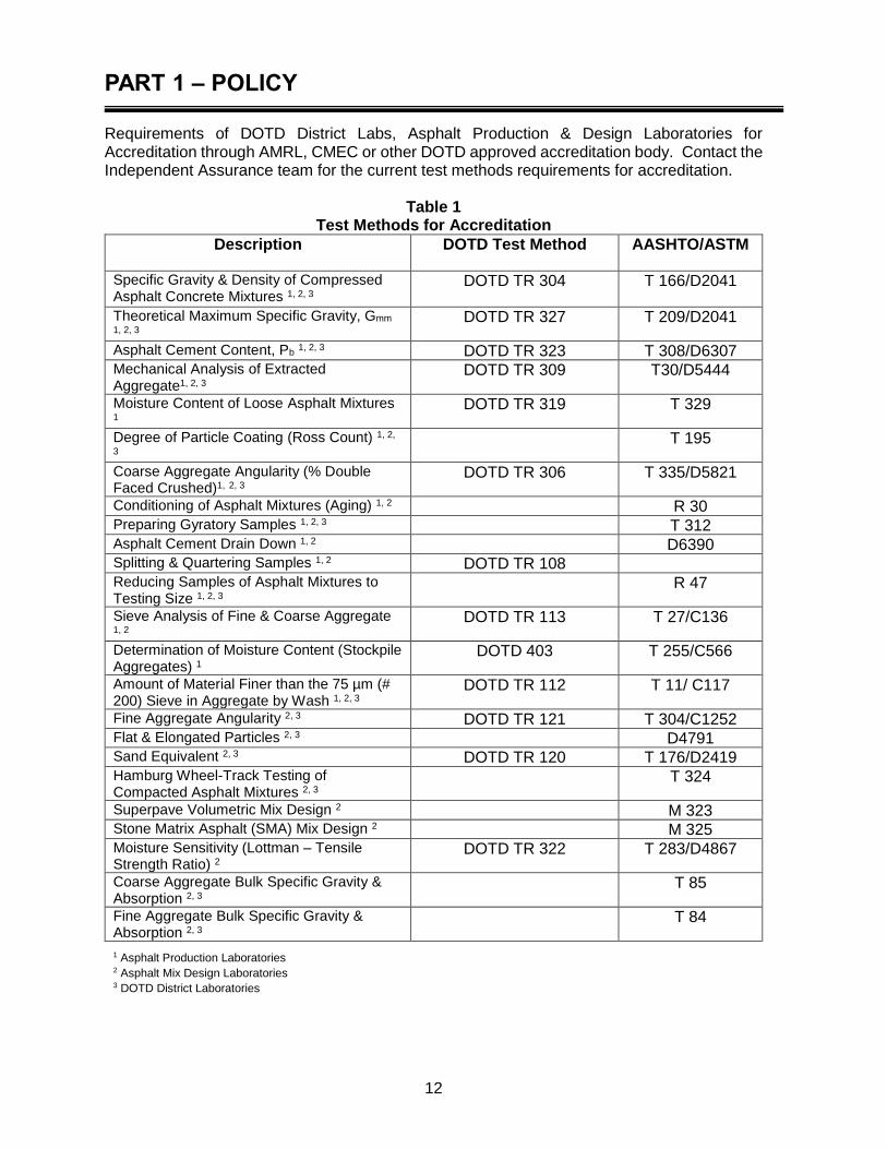
Requirements of DOTD District Labs, Asphalt Production & Design Laboratories for Accreditation through AMRL, CMEC or other DOTD approved accreditation body. Contact the Independent Assurance team for the current test methods requirements for accreditation.
Table 1 Test Methods for Accreditation
Description DOTD Test Method AASHTO/ASTM
Specific Gravity & Density of Compressed Asphalt Concrete Mixtures 1, 2, 3
DOTD TR 304 T 166/D2041
Theoretical Maximum Specific Gravity, Gmm 1, 2, 3
DOTD TR 327 T 209/D2041
Asphalt Cement Content, Pb 1, 2, 3 DOTD TR 323 T 308/D6307 Mechanical Analysis of Extracted Aggregate1, 2, 3
DOTD TR 309 T30/D5444
Moisture Content of Loose Asphalt Mixtures 1
DOTD TR 319 T 329
Degree of Particle Coating (Ross Count) 1, 2,
3 T 195
Coarse Aggregate Angularity (% Double Faced Crushed)1, 2, 3
DOTD TR 306 T 335/D5821
Conditioning of Asphalt Mixtures (Aging) 1, 2 R 30 Preparing Gyratory Samples 1, 2, 3 T 312 Asphalt Cement Drain Down 1, 2 D6390 Splitting & Quartering Samples 1, 2 DOTD TR 108 Reducing Samples of Asphalt Mixtures to Testing Size 1, 2, 3
R 47
Sieve Analysis of Fine & Coarse Aggregate 1, 2
DOTD TR 113 T 27/C136
Determination of Moisture Content (Stockpile Aggregates) 1
DOTD 403 T 255/C566
Amount of Material Finer than the 75 µm (# 200) Sieve in Aggregate by Wash 1, 2, 3
DOTD TR 112 T 11/ C117
Fine Aggregate Angularity 2, 3 DOTD TR 121 T 304/C1252 Flat & Elongated Particles 2, 3 D4791 Sand Equivalent 2, 3 DOTD TR 120 T 176/D2419 Hamburg Wheel-Track Testing of Compacted Asphalt Mixtures 2, 3
T 324
Superpave Volumetric Mix Design 2 M 323 Stone Matrix Asphalt (SMA) Mix Design 2 M 325 Moisture Sensitivity (Lottman – Tensile Strength Ratio) 2
DOTD TR 322 T 283/D4867
Coarse Aggregate Bulk Specific Gravity & Absorption 2, 3
T 85
Fine Aggregate Bulk Specific Gravity & Absorption 2, 3
T 84
1 Asphalt Production Laboratories 2 Asphalt Mix Design Laboratories 3 DOTD District Laboratories

PART 1 – POLICY
13
Independent Quality Assurance Program
Independent Assurance Programs
A system-based IA Program for asphalt materials will be employed which includes the maintenance of accreditation by all laboratories and maintenance of certification and proficiency of assessment of Certified Technicians. System independent assurance will include random plant and field visits to view test performance, verification of the calibration of equipment, and examination of the accreditation records. Independent Assurance is required for National Highway System (NHS) federal funding.
FHWA Technical Brief FHWA‐HIF‐12‐001 describes Code of Federal Regulations 23CFR637 that addresses the evaluation necessary for FHWA requirements. DOTD has changed to the “System Approach” for independent assurance where qualifications of involved personnel and facilities are assessed.
Independent Assurance
For asphalt mixture materials, the following proficiency tests will be required:
Table 2 Proficiency Sample Testing
Asphalt Samples Tests Frequency
Gyratory Briquettes, Gmb, Voids Minimum 1 per year
Loaded Wheel Test (Level 2 certification only)
AASHTO 324, Rut depth Minimum 1 per year
Oven Extracted Gradation %AC and % Passing each sieve.
Minimum 1 per year
Loose Mix Rice Gravity, Gmm Minimum 1 per year
Satisfactory performance for participants in the proficiency program will be test results less than 2 standard deviations from the mean.
System Independent Assurance Team
The system Independent Assurance team will be housed at the Training/IA lab at the Materials Lab and the personnel will be comprised of the Field Quality Assurance Engineer, the Independent Assurance Engineer, and Assurance Technician(s). The ADI in each District will also be responsible for assisting with the IA duties such as coordinating IA functions within their district. The team will perform the following:
1. Material Quantity Report: Annual Summary Report by district, by plant, by project, Technician to collect input data monthly.
2. Individual Lab review: Each district lab reviewed annually. a. Personnel and Equipment b. Lab Data
PART 1 – POLICY
14
3. Proficiency Sample Report: Annual report presentation of proficiency sample program
4. Accreditation/Certification report: Summary, annually report a listing all accredited labs, and dashboard of accreditations and equipment. (Monthly input by IA Technician or IA Engineer).
5. Independent Assurance (IA) Responsibilities for Plant Verification on System Based Frequency: The IA Inspector will randomly visit asphalt plant facilities on a system-based approach at a minimum frequency of 5% to verify plant operations and audit the quality of production with no advance notification to the contractor or the Department on all active projects each year. The IA Inspector is responsible for the following: The IA Inspector will either take a random independent sample or split sample with the Contractor during plant visits for each JMF being produced for state projects. Enough mix shall be sampled to complete the following tests:
Gmm – TR 327 - Completed during plant visit
Gyratory compacted to Ndesign – T 312, TR 304 – Completed during plant visit
Mix moisture – TR 319 - Completed during plant visit
Loose mix for %AC and gradation – TR 323, TR 309 – Either at the plant or IA lab.
The IA Inspector shall perform test independently of the Contractor. The cooled gyratory briquettes will be tested for bulk specific gravity Gmb, Va, %Gmm @ Ndes, VFA, and VMA. In addition, Quality Control charts, equipment maintenance logs, proficiency sample records, or other record keeping required for certification will be reviewed at the time of inspection. If the tolerances listed in Table 7 of the QA manual are not met, the IA Inspector will advise the Materials Engineer Administration for disposition and further handling.
6. Dispute Resolution, Forensic Analysis and Other Requests: When needed, the IA
team will be called upon to perform dispute resolution, forensic analysis and/or
technical assistance. Any of the nine District Laboratories or the Contractors certified
laboratory may be used at the direction of the Field Quality Assurance Engineer for
Dispute Resolution and/or Forensic Analysis. The IA Engineer and Technician (s) will
provide testing, documentation, and test reports to assist the DOTD in the dispute
resolution(s) and forensic analysis as needed.

PART 2 - DESIGN, PRODUCTION, AND ACCEPTANCE
15
Section 501 – Thin Asphalt Concrete Applications
This section describes the procedures and documentation required for designing, validating, and producing an asphalt concrete mixture for use on a DOTD project while applying Section 501 of the Standard Specifications (Thin Asphalt Concrete Applications). It also details plant Quality Control and acceptance, roadway Quality Control and acceptance, and how to pay for asphalt mix. This section shall be used in conjunction with Section 502 (Asphalt Concrete Mixtures) and Section 503 (Asphalt Concrete Equipment and Processes) of the Standard Specifications. However, information in this section also applies to Section 1002 (Asphalt Materials and Additives) and Section 1003 (Aggregates). The District Laboratory will verify the Contractor’s values of stockpile bulk specific gravities, absorption, and consensus properties. Verification of Contractor stockpiles for water absorption of 2.0% or less will be required for aggregates per 501.02.4 of the Standard Specifications by the District Laboratory.
Applicable test procedures are listed in Table 502-1 of the Standard Specifications. A copy of the following shall be available at the production facility:
Contract documents
Current edition of the Standard Specifications
Material Sampling Manual
All applicable testing procedures
Approved Materials List
JMF
R18 Documentation
Section 501 mixtures specifications differ from Section 502 in the methods and testing as describe herein.
Mix Design Steps and Approval
Material Procurement and Approval Material procurement and approval procedures are the same as for Section 502 except the Contractor will submit a Certificate of Analysis showing aggregate properties conforming to Table 501-2 and subsection 501.02.4.
Aggregate
Coarse Aggregate Coarse aggregates for use in Thin Lift Asphalt Concrete shall be listed on the Approved Materials List and meet the requirements of Subsections 1003.01 and 1003.06. The combined aggregates shall be in accordance with the design gradation requirements in Table 501-3. Friction requirement shall meet the requirements of Table 501-2.

PART 2 - DESIGN, PRODUCTION, AND ACCEPTANCE
16
Fine Aggregate Fine aggregates for use in Thin Lift shall be from aggregate sources listed on the Approved Materials List and meet requirement of Table 501-2. The Fine Aggregate Angularity (FAA) of each fine aggregate source shall be measured and the calculated average blend (AASHTO T 304) or weighted average of individual components shall be measured in accordance with DOTD TR 121 (mineral filler excluded). RAP RAP used in Dense Mix shall meet the RAP requirements referenced in sections 502.02.3.2, 1003.01.3.2, and 1003.06.5. Additional RAP percentages are not allowed in Dense Mix for pre-screening.
Asphalt Cement Asphalt cement shall be from an approved source listed on the Approved Materials List. Asphalt cement grade shall be in accordance with Table 501-1. Substitutions will be allowed in accordance with Section 501.02.2. Asphalt cement is accepted at the plant by a Certificate of Delivery (CD). A Certificate of Delivery shall accompany each load delivered to the plant. Asphalt cement testing shall be in accordance with Section 502.
Additives Anti-strip or hydrated lime (if used) shall meet the requirements of Section 501.02.3., and mineral filler (if used) shall meet the requirements of Section 501.02.5 Cellulose or mineral fibers, pre-approved by the Department, shall be used to prevent drain down as needed. The specific requirements for fibers are listed in Subsections 501.02.6 and Section 1002.02.5.
Design of Asphalt Mixture, Job Mix Formula (JMF)
Mix design steps and approval process are the same as for Section 502. Except for the
following requirements:
Determination of Gradation and Bulk Specific Gravity (Gsb) for Aggregates Procedures used to determine bulk specific gravity (Gsb) and gradation are the same as for Section 502, except that the gradation shall be as specified in Table 501-3. Ensure aggregates meet requirement of Table 501-2. Check that the certificate of analysis (CA) for Micro-Deval meets aggregate requirements of 502, 1003.01, and 1003.06.
Blending Aggregates to Meet Specified Gradation This procedure is the same as for Section 502.
Design of Blended Aggregates for Travel Lane Wearing Courses
Dense, Coarse, and OGFC (Open Graded Friction Course) Mixtures The compaction procedure is the same as for Section 502, except that the Gyratory Ndesign revolutions will be in accordance with Table 501-1.

PART 2 - DESIGN, PRODUCTION, AND ACCEPTANCE
17
Additional Requirements for OGFC Mixtures To ensure stone-on-stone contact of the aggregate blend, the following method shall be used when designing Thin Lift OGFC mixtures. For best performance, the OGFC mixture must have a coarse aggregate skeleton with stone-on-stone contact. The stone skeleton is that portion of the total aggregate blend retained on the No. 4 sieve. The condition of stone-on-stone contact within an OGFC mixture is defined as the point at which the percent voids of the compacted mixture is less than the Voids in Coarse Aggregate (VCA) in the dry-rodded test in accordance with AASHTO T 19/ASTM Test Method C29/C29M. The VCA of the coarse aggregate only fraction (VCADRC) is determined by compacting the stone with the dry-rodded technique according to ASTM Test Method C29/C29M. When the dry-rodded density of the coarse fraction has been determined, the VCADRC can be calculated using the following equation from ASTM Test Method C29/C29M:
100G
- G VCA
wCA
swCADRC x
Where:
GCA = Bulk specific gravity of the coarse aggregate γs = Bulk density of the coarse aggregate fraction in the dry-rodded condition, γw = Density of water
Va, and VCAMIX:
Select three trial blends of aggregate within the aggregate gradation bands as detailed in Table 501 - 3, “JMF Extracted Gradation and Production Tolerances.”
Determine the dry-rodded voids in the coarse aggregate, retained on the No. 4 (4.75 mm) sieve, of the coarse aggregate only, VCADRC as described above.
Add between 6.5% to 7.0% asphalt cement to each trial blend and compact blend to 50 gyrations in a Superpave gyratory compactor. (Note: At this stage of design, fiber should be added at the manufacturer’s recommended rate. Fibers are required only if the drain down requirements are not met. Typical fiber rates are 0.2% to 0.5% of the total weight [mass] of the mix.)
Determine the % air voids (Va), and % voids in the coarse aggregate for each of the compacted mixes (VCAMIX).
o Determine the bulk specific gravity of the mix (Gmb), using AASHTO T 166, the physical volume or vacuum sealing test method AASHTO T 331.
o Determine the theoretical maximum specific gravity of the mixture (Gmm), in accordance with DOTD TR 327.
o Determine the bulk specific gravity of the coarse aggregate fraction (GCA), in accordance with ASTM C127.
o Calculate Va, and VCAMIX using the following equations:
mm
mba
G
G1100V
PART 2 - DESIGN, PRODUCTION, AND ACCEPTANCE
18
CA
mbCAMIX
G
GP-100 VCA
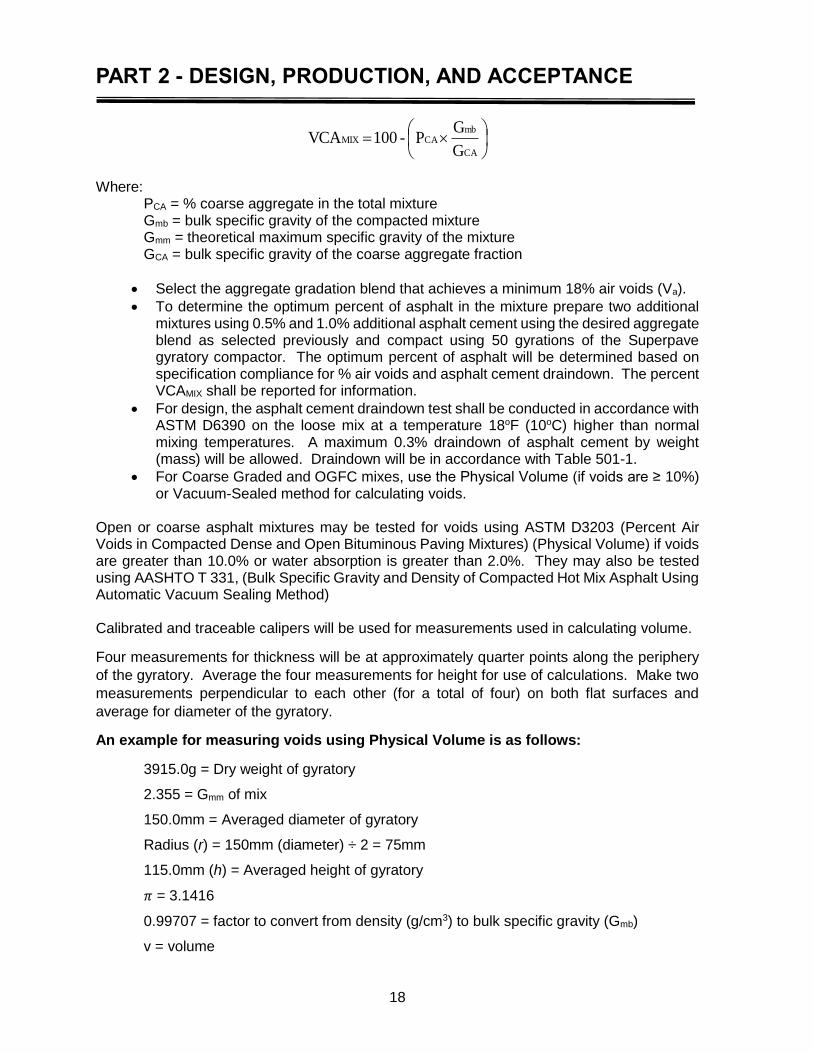
Where:
PCA = % coarse aggregate in the total mixture Gmb = bulk specific gravity of the compacted mixture Gmm = theoretical maximum specific gravity of the mixture GCA = bulk specific gravity of the coarse aggregate fraction
Select the aggregate gradation blend that achieves a minimum 18% air voids (Va).
To determine the optimum percent of asphalt in the mixture prepare two additional mixtures using 0.5% and 1.0% additional asphalt cement using the desired aggregate blend as selected previously and compact using 50 gyrations of the Superpave gyratory compactor. The optimum percent of asphalt will be determined based on specification compliance for % air voids and asphalt cement draindown. The percent VCAMIX shall be reported for information.
For design, the asphalt cement draindown test shall be conducted in accordance with ASTM D6390 on the loose mix at a temperature 18oF (10oC) higher than normal mixing temperatures. A maximum 0.3% draindown of asphalt cement by weight (mass) will be allowed. Draindown will be in accordance with Table 501-1.
For Coarse Graded and OGFC mixes, use the Physical Volume (if voids are ≥ 10%) or Vacuum-Sealed method for calculating voids.
Open or coarse asphalt mixtures may be tested for voids using ASTM D3203 (Percent Air Voids in Compacted Dense and Open Bituminous Paving Mixtures) (Physical Volume) if voids are greater than 10.0% or water absorption is greater than 2.0%. They may also be tested using AASHTO T 331, (Bulk Specific Gravity and Density of Compacted Hot Mix Asphalt Using Automatic Vacuum Sealing Method) Calibrated and traceable calipers will be used for measurements used in calculating volume.
Four measurements for thickness will be at approximately quarter points along the periphery
of the gyratory. Average the four measurements for height for use of calculations. Make two
measurements perpendicular to each other (for a total of four) on both flat surfaces and
average for diameter of the gyratory.
An example for measuring voids using Physical Volume is as follows:
3915.0g = Dry weight of gyratory
2.355 = Gmm of mix
150.0mm = Averaged diameter of gyratory
Radius (r) = 150mm (diameter) ÷ 2 = 75mm
115.0mm (h) = Averaged height of gyratory
𝜋 = 3.1416
0.99707 = factor to convert from density (g/cm3) to bulk specific gravity (Gmb)
v = volume
PART 2 - DESIGN, PRODUCTION, AND ACCEPTANCE
19
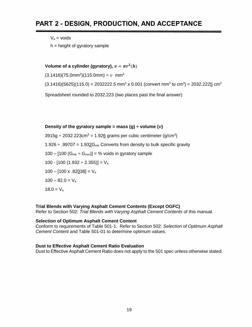
Va = voids
h = height of gyratory sample
Volume of a cylinder (gyratory), 𝒗 = 𝝅𝒓𝟐(𝒉)
(3.1416)(75.0mm2)(115.0mm) = 𝑣 mm3
(3.1416)(5625)(115.0) = 2032222.5 mm3 x 0.001 (convert mm3 to cm3) = 2032.2225 cm3
Spreadsheet rounded to 2032.223 (two places past the final answer)
Density of the gyratory sample = mass (g) ÷ volume (𝒗)
3915g ÷ 2032.223cm3 = 1.926 grams per cubic centimeter (g/cm3)
1.926 ÷ .99707 = 1.932Gmb Converts from density to bulk specific gravity
100 – [100 (Gmb ÷ Gmm)] = % voids in gyratory sample
100 - [100 (1.932 ÷ 2.355)] = Va
100 – [100 x .82038] = Va
100 – 82.0 = Va
18.0 = Va
Trial Blends with Varying Asphalt Cement Contents (Except OGFC) Refer to Section 502: Trial Blends with Varying Asphalt Cement Contents of this manual.
Selection of Optimum Asphalt Cement Content Conform to requirements of Table 501-1. Refer to Section 502: Selection of Optimum Asphalt Cement Content and Table 501-01 to determine optimum values.
Dust to Effective Asphalt Cement Ratio Evaluation Dust to Effective Asphalt Cement Ratio does not apply to the 501 spec unless otherwise stated.
PART 2 - DESIGN, PRODUCTION, AND ACCEPTANCE
20
LWT, Loaded Wheel Test, (AASHTO T 324) The Contractor will submit LWT results for specimens indicating conformance to Table 501-1. LWT may be tested at the plant laboratory or using the district laboratory LWT equipment.
Submittal Process and Documentation - JMF Proposal Form and Approval of JMF Proposal The process for submittal and approval of the JMF proposal are the same as for Section 502: Submittal Process and Documentation.
Approval of JMF proposal Refer to Section 502: Approval of JMF Proposal.
Validation of JMF proposal Validation procedures shall be in accordance with Subsection 501.05. In accordance with Section 501.04, a lot is defined as one segment of continuous production of asphalt concrete mixture from the same JMF produced for the Department at a specific plant, delivered to a specific project. A standard validation Lot is 1200 tons comprised of three 400-ton sublots. Test each sublot as follows:
One aggregate gradation and %AC
One briquette tested for volumetrics (Va)
One corresponding Maximum Theoretical Specific Gravity (Gmm) In addition, for the validation lot, take
One asphalt cement draindown (ASTM 6390) for OGFC and coarse mix
One % anti-strip additive rate verification
One Boil Test T 195
LWT (Rut Testing) Validation of JMF Proposal Pending acceptable validation results, moisture susceptibility testing (LWT testing) shall be performed the next day in accordance with Section 502: LWT (Rut Testing) Validation of JMF proposal. (A minimum of four roadway cores including the top lift of the underlying surface may be used for LWT testing.) Once completed, the validation data is promptly forwarded to the DLE, the average gradation and Gmm measured during validation will be become the JMF targets as per Table 501-4. The average of test results shall meet 100% pay requirements in Table 501-5 for job mix validation and final job mix formula approval, and the individual test result must meet the tolerances of Table 501-4. If the mix fails to validate, one additional attempt may be allowed by the DLE before requiring a redesign of the mixture. Upon validation of the JMF, the validation results shall be used for acceptance. The average of the validated results will become the JMF targets.
PART 2 - DESIGN, PRODUCTION, AND ACCEPTANCE
21
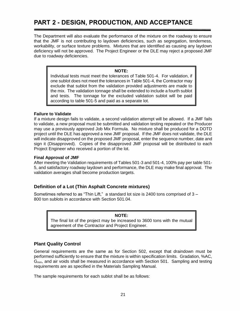
The Department will also evaluate the performance of the mixture on the roadway to ensure that the JMF is not contributing to laydown deficiencies, such as segregation, tenderness, workability, or surface texture problems. Mixtures that are identified as causing any laydown deficiency will not be approved. The Project Engineer or the DLE may reject a proposed JMF due to roadway deficiencies.
Failure to Validate If a mixture design fails to validate, a second validation attempt will be allowed. If a JMF fails to validate, a new proposal must be submitted and validation testing repeated or the Producer may use a previously approved Job Mix Formula. No mixture shall be produced for a DOTD project until the DLE has approved a new JMF proposal. If the JMF does not validate, the DLE will indicate disapproved on the proposed JMF proposal, enter the sequence number, date and sign it (Disapproved). Copies of the disapproved JMF proposal will be distributed to each Project Engineer who received a portion of the lot.
Final Approval of JMF After meeting the Validation requirements of Tables 501-3 and 501-4, 100% pay per table 501-5, and satisfactory roadway laydown and performance, the DLE may make final approval. The validation averages shall become production targets.
Definition of a Lot (Thin Asphalt Concrete mixtures)
Sometimes referred to as “Thin Lift,” a standard lot size is 2400 tons comprised of 3 – 800 ton sublots in accordance with Section 501.04.
Plant Quality Control
General requirements are the same as for Section 502, except that draindown must be performed sufficiently to ensure that the mixture is within specification limits. Gradation, %AC, Gmm, and air voids shall be measured in accordance with Section 501. Sampling and testing requirements are as specified in the Materials Sampling Manual. The sample requirements for each sublot shall be as follows:
NOTE: Individual tests must meet the tolerances of Table 501-4. For validation, if one sublot does not meet the tolerances in Table 501-4, the Contractor may exclude that sublot from the validation provided adjustments are made to the mix. The validation tonnage shall be extended to include a fourth sublot and tests. The tonnage for the excluded validation sublot will be paid according to table 501-5 and paid as a separate lot.
NOTE: The final lot of the project may be increased to 3600 tons with the mutual agreement of the Contractor and Project Engineer.
PART 2 - DESIGN, PRODUCTION, AND ACCEPTANCE
22
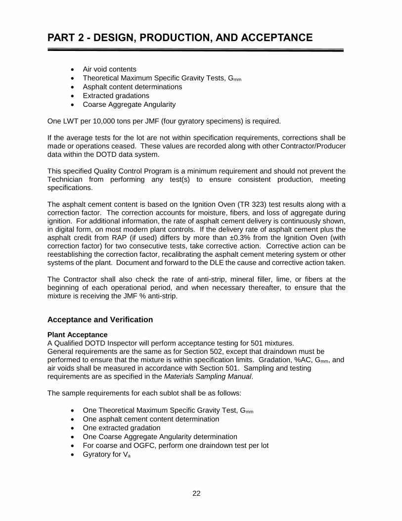
Air void contents
Theoretical Maximum Specific Gravity Tests, Gmm
Asphalt content determinations
Extracted gradations
Coarse Aggregate Angularity One LWT per 10,000 tons per JMF (four gyratory specimens) is required. If the average tests for the lot are not within specification requirements, corrections shall be made or operations ceased. These values are recorded along with other Contractor/Producer data within the DOTD data system. This specified Quality Control Program is a minimum requirement and should not prevent the Technician from performing any test(s) to ensure consistent production, meeting specifications. The asphalt cement content is based on the Ignition Oven (TR 323) test results along with a correction factor. The correction accounts for moisture, fibers, and loss of aggregate during ignition. For additional information, the rate of asphalt cement delivery is continuously shown, in digital form, on most modern plant controls. If the delivery rate of asphalt cement plus the asphalt credit from RAP (if used) differs by more than ±0.3% from the Ignition Oven (with correction factor) for two consecutive tests, take corrective action. Corrective action can be reestablishing the correction factor, recalibrating the asphalt cement metering system or other systems of the plant. Document and forward to the DLE the cause and corrective action taken. The Contractor shall also check the rate of anti-strip, mineral filler, lime, or fibers at the beginning of each operational period, and when necessary thereafter, to ensure that the mixture is receiving the JMF % anti-strip.
Acceptance and Verification
Plant Acceptance A Qualified DOTD Inspector will perform acceptance testing for 501 mixtures. General requirements are the same as for Section 502, except that draindown must be performed to ensure that the mixture is within specification limits. Gradation, %AC, Gmm, and air voids shall be measured in accordance with Section 501. Sampling and testing requirements are as specified in the Materials Sampling Manual. The sample requirements for each sublot shall be as follows:
One Theoretical Maximum Specific Gravity Test, Gmm
One asphalt cement content determination
One extracted gradation
One Coarse Aggregate Angularity determination
For coarse and OGFC, perform one draindown test per lot
Gyratory for Va
PART 2 - DESIGN, PRODUCTION, AND ACCEPTANCE
23
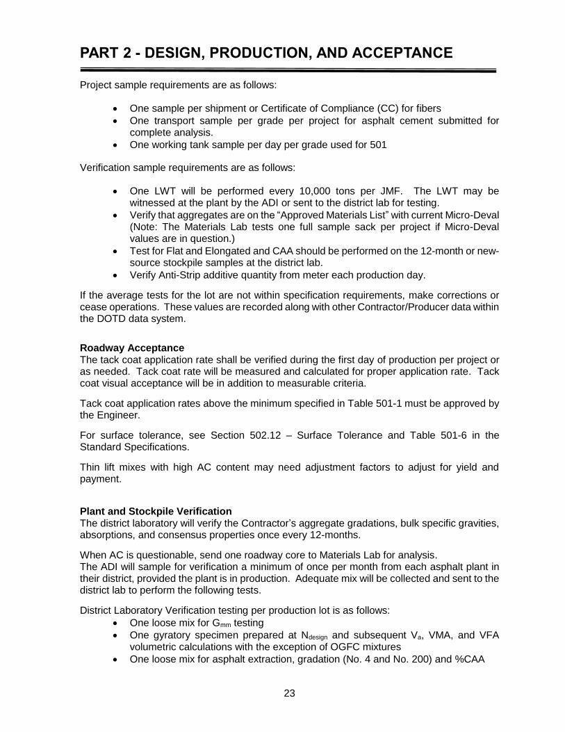
Project sample requirements are as follows:
One sample per shipment or Certificate of Compliance (CC) for fibers
One transport sample per grade per project for asphalt cement submitted for complete analysis.
One working tank sample per day per grade used for 501
Verification sample requirements are as follows:
One LWT will be performed every 10,000 tons per JMF. The LWT may be witnessed at the plant by the ADI or sent to the district lab for testing.
Verify that aggregates are on the “Approved Materials List” with current Micro-Deval (Note: The Materials Lab tests one full sample sack per project if Micro-Deval values are in question.)
Test for Flat and Elongated and CAA should be performed on the 12-month or new-source stockpile samples at the district lab.
Verify Anti-Strip additive quantity from meter each production day.
If the average tests for the lot are not within specification requirements, make corrections or cease operations. These values are recorded along with other Contractor/Producer data within the DOTD data system.
Roadway Acceptance The tack coat application rate shall be verified during the first day of production per project or as needed. Tack coat rate will be measured and calculated for proper application rate. Tack coat visual acceptance will be in addition to measurable criteria.
Tack coat application rates above the minimum specified in Table 501-1 must be approved by the Engineer.
For surface tolerance, see Section 502.12 – Surface Tolerance and Table 501-6 in the Standard Specifications.
Thin lift mixes with high AC content may need adjustment factors to adjust for yield and payment.
Plant and Stockpile Verification The district laboratory will verify the Contractor’s aggregate gradations, bulk specific gravities, absorptions, and consensus properties once every 12-months.
When AC is questionable, send one roadway core to Materials Lab for analysis. The ADI will sample for verification a minimum of once per month from each asphalt plant in their district, provided the plant is in production. Adequate mix will be collected and sent to the district lab to perform the following tests.
District Laboratory Verification testing per production lot is as follows:
One loose mix for Gmm testing
One gyratory specimen prepared at Ndesign and subsequent Va, VMA, and VFA volumetric calculations with the exception of OGFC mixtures
One loose mix for asphalt extraction, gradation (No. 4 and No. 200) and %CAA
PART 2 - DESIGN, PRODUCTION, AND ACCEPTANCE
24
Measurement and Payment
Measurement Weight measure by the ton will be based on Section 502. Measure the square yards paved and total gallons of tack coat applied. Report in gallons per square yards. Record tonnage received based on truck tickets as delivered to roadway.
Payment Payment for Thin Asphalt Concrete mixtures will be made at the contract unit price per ton. Apply pay adjustment based on Table 501-5 for Gmm and Gradation. Pay adjustment is the lowest determined value. Asphalt tack coat will not be a pay item and will be considered incidental to the 501 item. It will be applied in accordance with Section 504. If the engineer adjusts the application rate of tack coat from that specified by the contract document, payment for the asphalt mixture will be increased or decreased based on the difference in the applied quantity of asphalt emulsion shown on paid invoices. The contractor shall provide copies of paid invoices for this determination.
PART 2 - DESIGN, PRODUCTION, AND ACCEPTANCE
25
Section 502 – Asphalt Concrete Mixtures
This section describes the procedures and documentation required for designing, validating, and producing an asphalt concrete mixture for use on a DOTD project while applying Section 502 of the Standard Specifications (Asphalt Concrete Mixtures). It also details Plant Quality Control and Acceptance, Roadway Quality Control and Acceptance, and How to Pay for Asphalt Mix. Sections 503 (Asphalt Concrete Equipment and Processes), 1002 (Asphalt Materials and Additives) and 1003 (Aggregates) also apply. Applicable test procedures are listed in Table 502-1 of the Standard Specifications. A copy of each applicable test procedure shall be available at the plant for immediate reference. The preface contains a listing of appropriate manuals. Warm Mix Asphalt (WMA) is defined as asphalt concrete mixture that is modified by approved foaming methods or chemical additives to reduce mixing and compaction temperatures.
Mix Design Steps and Approval
Material Procurement and Approval The Contractor selects and procures materials to utilize in the mix design process. Materials for an asphalt mix design include, but are not limited to, aggregates, asphalt cement, and anti-strip. Source Approval–All materials are assigned an approved brand name or on the Approved Materials List (AML).
Aggregate All aggregates will be submitted to the district laboratory for verification. Stockpile Samples–Stockpile samples are to be tested for verification of the Contractor’s submitted values every 12-months. Samples for new sources are to be submitted at least three weeks prior to the submission of a job mix proposal (JMF). No proposed JMF will be accepted until all mix components have been approved. RAP will be sampled and tested every six-months. The contractor will report QC results for aggregate properties when the district lab tests for verification and again in six months. The contractor’s six-month interval report between district lab verification testing will include Gsb, absorption, and gradation. Qualification requirements for coarse aggregate and fine aggregates will comply with section 1003.06 and 502.02.3 Aggregates. In addition, plus No. 4 material is considered coarse aggregate and minus No. 4 material is considered fine aggregate. If more than 10% material passes the No. 4 of a primarily coarse material or more than 10% material is retained on the No. 4 of a primarily fine material, tests for both coarse and fine aggregate will be performed respectively. Aggregates that are tested for fine and coarse properties will be mathematically combined for a single value.
PART 2 - DESIGN, PRODUCTION, AND ACCEPTANCE
26
Blended aggregates shall comply with Table 502-6 Asphalt Concrete General Criteria and Table 502-4 Plant Produced Asphalt Mixture Requirements and Tolerances. Reclaimed Asphalt Pavement (RAP) will be allowed in 502 mixtures at specified percentages. RAP will be tested for Gmm, %AC and gradation. Gse will be calculated from the Gmm, and then a Gsb will be calculated from the Gse. Working stockpiles of RAP must be verified by the District Lab, receiving an approved Site Manager Materials “Producer Supplier” code (PS code). RAP shall be cold planed in accordance with Section 509, and shall meet the requirements of Section 1003.
The percent moisture, %AC, gradation, Gmm, calculated Gse and calculated Gsb of RAP shall be reported to the District Lab by the Contractor when stockpile verification samples are taken. The procedures are in the Determination of Gradation and Bulk Specific Gravity (Gsb) for Aggregates section of this manual.
Additional RAP is allowed in 502 mixes except for airports and SMA when:
RAP is stockpiled separately with all material passing a 1 in. screen.
When RAP is pre-screened over 1 in. screen, an additional 5% RAP can be added for mixes that allow RAP.
Mixes with the 5% additional RAP must meet all specifications and perform satisfactory.
Friction Rating - For travel lane wearing courses, the total aggregate combination shall comply with Table 502-3 Aggregate Friction Rating. This table specifies allowable usage according to mixture type and Average Daily Traffic (ADT). The mixture type will be shown on the pavement typical sections in the contract plans.
Asphalt Cement Asphalt cement will be on the AML. Asphalt cement grade shall comply with Subsections 1002 and 502.02.1 and Table 502-2 – Asphalt Cement Usage. Substitutions are allowed in accordance with Table 502-2. A Certificate of Delivery/Analysis shall accompany each load delivered to the plant. The District Laboratory will test working tank samples. The Materials Laboratory will request the District Laboratory sample transports for refinery verification samples. District Lab employees will coordinate plant production and transport delivery with Materials Laboratory sample request.
Additives Anti-strip shall be added to all mixtures and in an amount determined in accordance with Subsection 502.02.2.1. Anti-strip used shall be in the Approved Materials List. A Certificate of Delivery for Asphalt Anti-strip Additives shall accompany each load of anti-strip.
Hydrated lime, if used, shall be in accordance with Subsection 502.02.2.2 and from a source listed in the AML. The minimum rate shall not be less than 1.5% by weight of the total mixture. Further, hydrated lime shall be added to and thoroughly mixed with aggregates in accordance with Subsection 502.02.2.2. Hydrated lime may be also added as mineral filler in accordance with Subsection 502.02.3.3. A Certificate of Delivery shall accompany each load of hydrated lime.
Mineral filler, if used, shall be in accordance with Subsection 502.02.3.3 and Subsection 1003.06.1.6 and an approved product listed in the AML. It shall consist of limestone dust, pulverized hydrated lime, Portland cement, or cement stack dust. A Certificate of Delivery,
PART 2 - DESIGN, PRODUCTION, AND ACCEPTANCE
27
matching a format similar to the CD for Asphalt Materials, shall accompany each load of mineral filler. Waste Tire Rubber additive, if used, shall be blended with an AML PG 67-22 material. Add Crumb rubber as required to meet grade PG 82-22rm. Use a maximum size rubber particle of 30 mesh crumb (90-100% passing the No. 30 sieve). In accordance with 1002.02.2, Waste Tire Rubber additive will require the Contractor to perform DSR testing of the blended material. Latex Additive, if used, shall be in accordance with Subsection 502.02.2.4. Latex added at the Contractor’s plant shall be blended at a minimum of 1.0% residual latex by weight of asphalt cement to an AML PG 67-22 material and in accordance with Section 503.05.2. Latex blended asphalt shall meet PG 70-22m specification requirements using pre-qualified asphalt material and latex. Latex additive will require that the Contractor to perform DSR testing of the blended material. Fibers, if used, shall be in accordance with Subsection 1002.02.5. Fibers shall be a cellulose or mineral fiber. Fibers shall be added at a minimum rate of 0.1% by weight (mass) of mixture and at a rate sufficient to prevent draindown. Natural sand, if used, shall be in accordance with the requirements of Table 502-6 and Section 1003.06.3. Warm Mix additives, if used, shall be in accordance with Section 1002.02.4.
Design of Asphalt Mixture, Job Mix Formula (JMF) Listed below are the general steps required to design, validate, and approve an asphalt mixture according to Section 502. Using the material and procurement process listed above, proceed with the following steps for approval of JMFs.
Determination of Gradation and Bulk Specific Gravity (Gsb) for Aggregates
Gradation
The Contractor shall obtain a sample from each proposed stockpile for gradation determination. An accurate gradation analysis is required for blending analysis, and the determination of the consistency of incoming material. The District Lab will perform gradation testing on 12-month stockpile verifications. RAP will be sampled and tested from each asphalt plant every six-months. It is recommended that the Contractor secure samples of all bulk shipments of aggregates delivered to the plant site. The gradation results of these shipments should be determined prior to their addition to a working stockpile. Documentation of these continuous stockpile gradation and specific gravity results shall be kept on file so that varying trends of the aggregate source may be determined. The Contractor shall report stockpile gradations to the DLE every 12-months along with Gsb, absorption, and consensus properties. RAP will be every six-months.
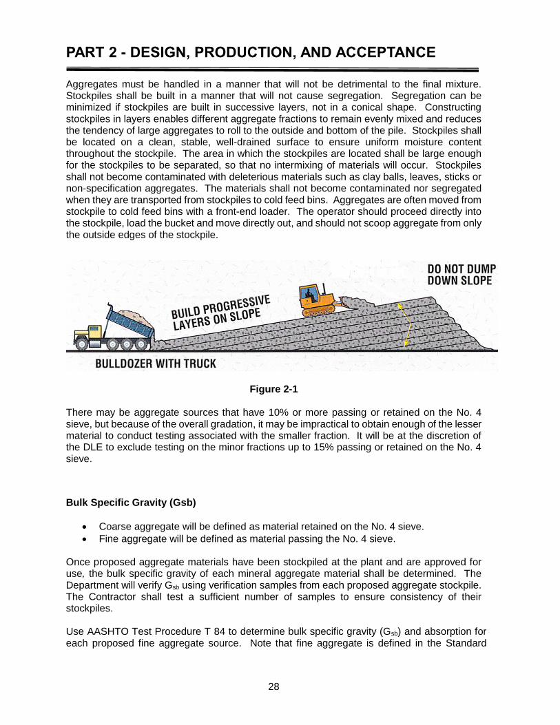
PART 2 - DESIGN, PRODUCTION, AND ACCEPTANCE
28
Aggregates must be handled in a manner that will not be detrimental to the final mixture. Stockpiles shall be built in a manner that will not cause segregation. Segregation can be minimized if stockpiles are built in successive layers, not in a conical shape. Constructing stockpiles in layers enables different aggregate fractions to remain evenly mixed and reduces the tendency of large aggregates to roll to the outside and bottom of the pile. Stockpiles shall be located on a clean, stable, well-drained surface to ensure uniform moisture content throughout the stockpile. The area in which the stockpiles are located shall be large enough for the stockpiles to be separated, so that no intermixing of materials will occur. Stockpiles shall not become contaminated with deleterious materials such as clay balls, leaves, sticks or non-specification aggregates. The materials shall not become contaminated nor segregated when they are transported from stockpiles to cold feed bins. Aggregates are often moved from stockpile to cold feed bins with a front-end loader. The operator should proceed directly into the stockpile, load the bucket and move directly out, and should not scoop aggregate from only the outside edges of the stockpile.
Figure 2-1
There may be aggregate sources that have 10% or more passing or retained on the No. 4 sieve, but because of the overall gradation, it may be impractical to obtain enough of the lesser material to conduct testing associated with the smaller fraction. It will be at the discretion of the DLE to exclude testing on the minor fractions up to 15% passing or retained on the No. 4 sieve.
Bulk Specific Gravity (Gsb)
Coarse aggregate will be defined as material retained on the No. 4 sieve.
Fine aggregate will be defined as material passing the No. 4 sieve. Once proposed aggregate materials have been stockpiled at the plant and are approved for use, the bulk specific gravity of each mineral aggregate material shall be determined. The Department will verify Gsb using verification samples from each proposed aggregate stockpile. The Contractor shall test a sufficient number of samples to ensure consistency of their stockpiles. Use AASHTO Test Procedure T 84 to determine bulk specific gravity (Gsb) and absorption for each proposed fine aggregate source. Note that fine aggregate is defined in the Standard
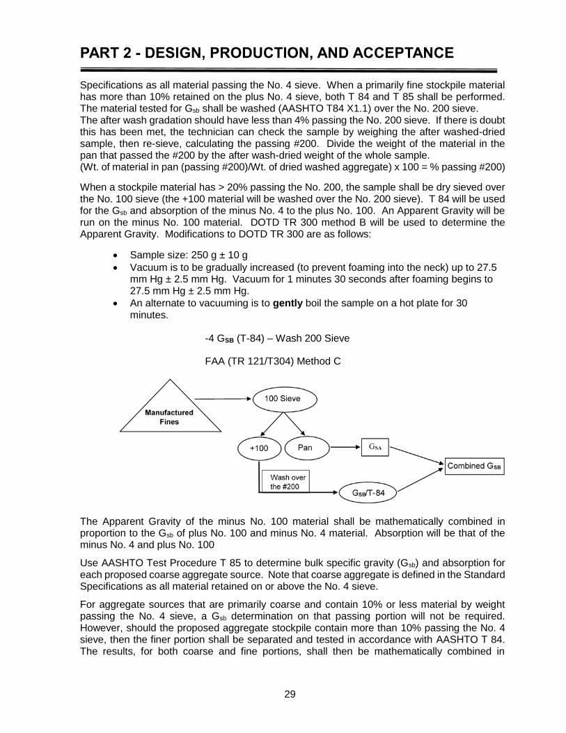
PART 2 - DESIGN, PRODUCTION, AND ACCEPTANCE
29
Specifications as all material passing the No. 4 sieve. When a primarily fine stockpile material has more than 10% retained on the plus No. 4 sieve, both T 84 and T 85 shall be performed. The material tested for Gsb shall be washed (AASHTO T84 X1.1) over the No. 200 sieve. The after wash gradation should have less than 4% passing the No. 200 sieve. If there is doubt this has been met, the technician can check the sample by weighing the after washed-dried sample, then re-sieve, calculating the passing #200. Divide the weight of the material in the pan that passed the #200 by the after wash-dried weight of the whole sample. (Wt. of material in pan (passing #200)/Wt. of dried washed aggregate) x 100 = % passing #200)
When a stockpile material has > 20% passing the No. 200, the sample shall be dry sieved over the No. 100 sieve (the +100 material will be washed over the No. 200 sieve). T 84 will be used for the Gsb and absorption of the minus No. 4 to the plus No. 100. An Apparent Gravity will be run on the minus No. 100 material. DOTD TR 300 method B will be used to determine the Apparent Gravity. Modifications to DOTD TR 300 are as follows:
Sample size: 250 g ± 10 g
Vacuum is to be gradually increased (to prevent foaming into the neck) up to 27.5 mm Hg ± 2.5 mm Hg. Vacuum for 1 minutes 30 seconds after foaming begins to 27.5 mm Hg ± 2.5 mm Hg.
An alternate to vacuuming is to gently boil the sample on a hot plate for 30 minutes.
-4 GSB (T-84) – Wash 200 Sieve
FAA (TR 121/T304) Method C
The Apparent Gravity of the minus No. 100 material shall be mathematically combined in proportion to the Gsb of plus No. 100 and minus No. 4 material. Absorption will be that of the minus No. 4 and plus No. 100
Use AASHTO Test Procedure T 85 to determine bulk specific gravity (Gsb) and absorption for each proposed coarse aggregate source. Note that coarse aggregate is defined in the Standard Specifications as all material retained on or above the No. 4 sieve.
For aggregate sources that are primarily coarse and contain 10% or less material by weight passing the No. 4 sieve, a Gsb determination on that passing portion will not be required. However, should the proposed aggregate stockpile contain more than 10% passing the No. 4 sieve, then the finer portion shall be separated and tested in accordance with AASHTO T 84. The results, for both coarse and fine portions, shall then be mathematically combined in
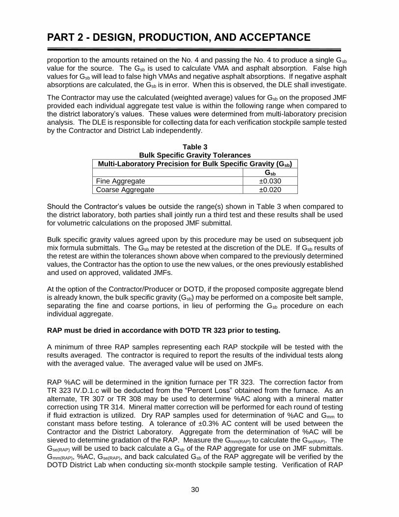
PART 2 - DESIGN, PRODUCTION, AND ACCEPTANCE
30
proportion to the amounts retained on the No. 4 and passing the No. 4 to produce a single Gsb value for the source. The Gsb is used to calculate VMA and asphalt absorption. False high values for Gsb will lead to false high VMAs and negative asphalt absorptions. If negative asphalt absorptions are calculated, the Gsb is in error. When this is observed, the DLE shall investigate.
The Contractor may use the calculated (weighted average) values for Gsb on the proposed JMF provided each individual aggregate test value is within the following range when compared to the district laboratory’s values. These values were determined from multi-laboratory precision analysis. The DLE is responsible for collecting data for each verification stockpile sample tested by the Contractor and District Lab independently.
Table 3
Bulk Specific Gravity Tolerances
Multi-Laboratory Precision for Bulk Specific Gravity (Gsb)
Gsb
Fine Aggregate ±0.030
Coarse Aggregate ±0.020
Should the Contractor’s values be outside the range(s) shown in Table 3 when compared to the district laboratory, both parties shall jointly run a third test and these results shall be used for volumetric calculations on the proposed JMF submittal. Bulk specific gravity values agreed upon by this procedure may be used on subsequent job mix formula submittals. The Gsb may be retested at the discretion of the DLE. If Gsb results of the retest are within the tolerances shown above when compared to the previously determined values, the Contractor has the option to use the new values, or the ones previously established and used on approved, validated JMFs. At the option of the Contractor/Producer or DOTD, if the proposed composite aggregate blend is already known, the bulk specific gravity (Gsb) may be performed on a composite belt sample, separating the fine and coarse portions, in lieu of performing the Gsb procedure on each individual aggregate. RAP must be dried in accordance with DOTD TR 323 prior to testing. A minimum of three RAP samples representing each RAP stockpile will be tested with the results averaged. The contractor is required to report the results of the individual tests along with the averaged value. The averaged value will be used on JMFs.
RAP %AC will be determined in the ignition furnace per TR 323. The correction factor from TR 323 IV.D.1.c will be deducted from the “Percent Loss” obtained from the furnace. As an alternate, TR 307 or TR 308 may be used to determine %AC along with a mineral matter correction using TR 314. Mineral matter correction will be performed for each round of testing if fluid extraction is utilized. Dry RAP samples used for determination of %AC and Gmm to constant mass before testing. A tolerance of ±0.3% AC content will be used between the Contractor and the District Laboratory. Aggregate from the determination of %AC will be sieved to determine gradation of the RAP. Measure the Gmm(RAP) to calculate the Gse(RAP). The Gse(RAP) will be used to back calculate a Gsb of the RAP aggregate for use on JMF submittals. Gmm(RAP), %AC, Gse(RAP), and back calculated Gsb of the RAP aggregate will be verified by the DOTD District Lab when conducting six-month stockpile sample testing. Verification of RAP
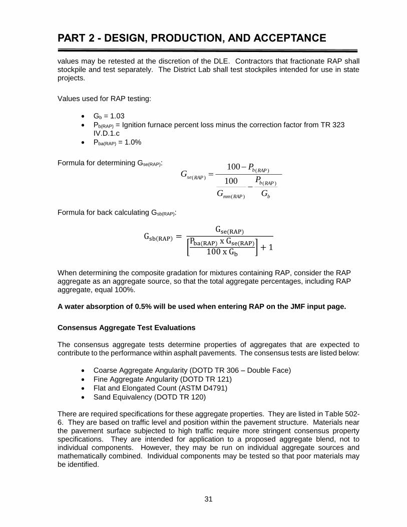
PART 2 - DESIGN, PRODUCTION, AND ACCEPTANCE
31
values may be retested at the discretion of the DLE. Contractors that fractionate RAP shall stockpile and test separately. The District Lab shall test stockpiles intended for use in state projects.
Values used for RAP testing:
Gb = 1.03
Pb(RAP) = Ignition furnace percent loss minus the correction factor from TR 323 IV.D.1.c
Pba(RAP) = 1.0%
Formula for determining Gse(RAP):
Formula for back calculating Gsb(RAP):
Gsb(RAP) = Gse(RAP)
[Pba(RAP) x Gse(RAP)
100 x Gb] + 1
When determining the composite gradation for mixtures containing RAP, consider the RAP aggregate as an aggregate source, so that the total aggregate percentages, including RAP aggregate, equal 100%. A water absorption of 0.5% will be used when entering RAP on the JMF input page.
Consensus Aggregate Test Evaluations The consensus aggregate tests determine properties of aggregates that are expected to contribute to the performance within asphalt pavements. The consensus tests are listed below:
Coarse Aggregate Angularity (DOTD TR 306 – Double Face)
Fine Aggregate Angularity (DOTD TR 121)
Flat and Elongated Count (ASTM D4791)
Sand Equivalency (DOTD TR 120) There are required specifications for these aggregate properties. They are listed in Table 502-6. They are based on traffic level and position within the pavement structure. Materials near the pavement surface subjected to high traffic require more stringent consensus property specifications. They are intended for application to a proposed aggregate blend, not to individual components. However, they may be run on individual aggregate sources and mathematically combined. Individual components may be tested so that poor materials may be identified.
b
RAPb
RAPmm
RAPb
RAPse
G
P
G
PG
)(
)(
)(
)(100
100
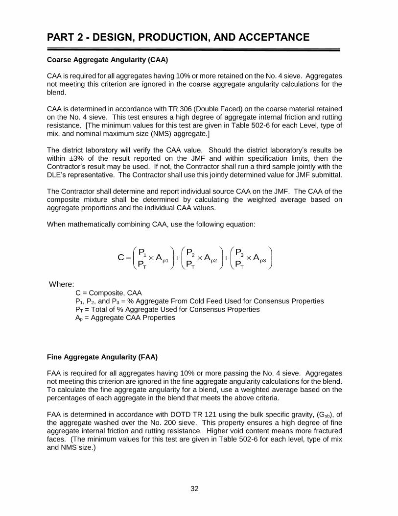
PART 2 - DESIGN, PRODUCTION, AND ACCEPTANCE
32
Coarse Aggregate Angularity (CAA)
CAA is required for all aggregates having 10% or more retained on the No. 4 sieve. Aggregates not meeting this criterion are ignored in the coarse aggregate angularity calculations for the blend. CAA is determined in accordance with TR 306 (Double Faced) on the coarse material retained on the No. 4 sieve. This test ensures a high degree of aggregate internal friction and rutting resistance. [The minimum values for this test are given in Table 502-6 for each Level, type of mix, and nominal maximum size (NMS) aggregate.] The district laboratory will verify the CAA value. Should the district laboratory’s results be within ±3% of the result reported on the JMF and within specification limits, then the Contractor’s result may be used. If not, the Contractor shall run a third sample jointly with the DLE’s representative. The Contractor shall use this jointly determined value for JMF submittal. The Contractor shall determine and report individual source CAA on the JMF. The CAA of the composite mixture shall be determined by calculating the weighted average based on aggregate proportions and the individual CAA values. When mathematically combining CAA, use the following equation:
p3
T
3p2
T
2p1
T
1 AP
PA
P
PA
P
PC
Where: C = Composite, CAA P1, P2, and P3 = % Aggregate From Cold Feed Used for Consensus Properties PT = Total of % Aggregate Used for Consensus Properties Ap = Aggregate CAA Properties
Fine Aggregate Angularity (FAA)
FAA is required for all aggregates having 10% or more passing the No. 4 sieve. Aggregates not meeting this criterion are ignored in the fine aggregate angularity calculations for the blend. To calculate the fine aggregate angularity for a blend, use a weighted average based on the percentages of each aggregate in the blend that meets the above criteria. FAA is determined in accordance with DOTD TR 121 using the bulk specific gravity, (Gsb), of the aggregate washed over the No. 200 sieve. This property ensures a high degree of fine aggregate internal friction and rutting resistance. Higher void content means more fractured faces. (The minimum values for this test are given in Table 502-6 for each level, type of mix and NMS size.)
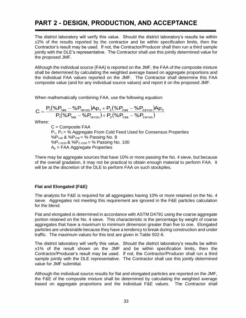
PART 2 - DESIGN, PRODUCTION, AND ACCEPTANCE
33
The district laboratory will verify this value. Should the district laboratory’s results be within ±2% of the results reported by the contractor and be within specification limits, then the Contractor’s result may be used. If not, the Contractor/Producer shall then run a third sample jointly with the DLE’s representative. The Contractor shall use this jointly determined value for the proposed JMF. Although the individual source (FAA) is reported on the JMF, the FAA of the composite mixture shall be determined by calculating the weighted average based on aggregate proportions and the individual FAA values reported on the JMF. The Contractor shall determine this FAA composite value (and for any individual source values) and report it on the proposed JMF.
When mathematically combining FAA, use the following equation:
#1002#822#1001#811
2#1002#8221#1001#811
%P%PP%P%PP
Ap%P%PPAp%P%PPC
Where: C = Composite FAA P1, P2 = % Aggregate From Cold Feed Used for Consensus Properties %P1#8 & %P2#8 = % Passing No. 8 %P1 #100 & %P2 #100 = % Passing No. 100 Ap = FAA Aggregate Properties
There may be aggregate sources that have 10% or more passing the No. 4 sieve, but because of the overall gradation, it may not be practical to obtain enough material to perform FAA. It will be at the discretion of the DLE to perform FAA on such stockpiles.
Flat and Elongated (F&E)
The analysis for F&E is required for all aggregates having 10% or more retained on the No. 4 sieve. Aggregates not meeting this requirement are ignored in the F&E particles calculation for the blend.
Flat and elongated is determined in accordance with ASTM D4791 using the coarse aggregate portion retained on the No. 4 sieve. This characteristic is the percentage by weight of coarse aggregates that have a maximum to minimum dimension greater than five to one. Elongated particles are undesirable because they have a tendency to break during construction and under traffic. The maximum values for this test are given in Table 502-6.
The district laboratory will verify this value. Should the district laboratory’s results be within ±1% of the result shown on the JMF and be within specification limits, then the Contractor/Producer’s result may be used. If not, the Contractor/Producer shall run a third sample jointly with the DLE representative. The Contractor shall use this jointly determined value for JMF submittal.
Although the individual source results for flat and elongated particles are reported on the JMF, the F&E of the composite mixture shall be determined by calculating the weighted average based on aggregate proportions and the individual F&E values. The Contractor shall
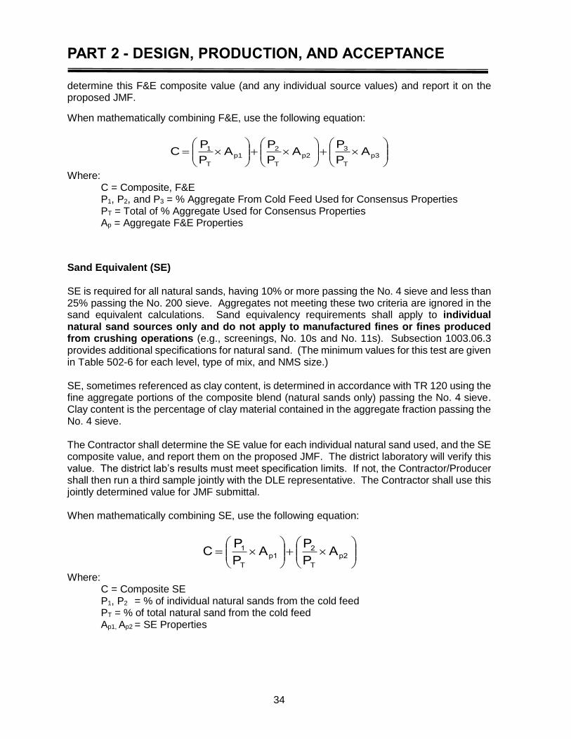
PART 2 - DESIGN, PRODUCTION, AND ACCEPTANCE
34
determine this F&E composite value (and any individual source values) and report it on the proposed JMF.
When mathematically combining F&E, use the following equation:
p3
T
3p2
T
2p1
T
1 AP
PA
P
PA
P
PC
Where: C = Composite, F&E P1, P2, and P3 = % Aggregate From Cold Feed Used for Consensus Properties PT = Total of % Aggregate Used for Consensus Properties Ap = Aggregate F&E Properties
Sand Equivalent (SE) SE is required for all natural sands, having 10% or more passing the No. 4 sieve and less than 25% passing the No. 200 sieve. Aggregates not meeting these two criteria are ignored in the sand equivalent calculations. Sand equivalency requirements shall apply to individual natural sand sources only and do not apply to manufactured fines or fines produced from crushing operations (e.g., screenings, No. 10s and No. 11s). Subsection 1003.06.3 provides additional specifications for natural sand. (The minimum values for this test are given in Table 502-6 for each level, type of mix, and NMS size.) SE, sometimes referenced as clay content, is determined in accordance with TR 120 using the fine aggregate portions of the composite blend (natural sands only) passing the No. 4 sieve. Clay content is the percentage of clay material contained in the aggregate fraction passing the No. 4 sieve. The Contractor shall determine the SE value for each individual natural sand used, and the SE composite value, and report them on the proposed JMF. The district laboratory will verify this value. The district lab’s results must meet specification limits. If not, the Contractor/Producer shall then run a third sample jointly with the DLE representative. The Contractor shall use this jointly determined value for JMF submittal. When mathematically combining SE, use the following equation:
p2
T
2p1
T
1 AP
PA
P
PC
Where: C = Composite SE P1, P2 = % of individual natural sands from the cold feed PT = % of total natural sand from the cold feed Ap1, Ap2 = SE Properties

PART 2 - DESIGN, PRODUCTION, AND ACCEPTANCE
35
Table 4 Contractor and DOTD Tolerances for Stockpile Testing
Test Description Tolerance
T 84 AASHTO Gsb of Fine Aggregate ±0.030
T 85 AASHTO Gsb of Coarse Aggregate ±0.020
TR 121 Fine Aggregate Angularity (FAA) ±2*
TR 306 Coarse Aggregate Angularity (CAA) ± 3%*
ASTM D4791 Flat and Elongated (5:1) ±1*
TR 120 Sand Equivalent Within specifications
* Both DOTD district laboratory and the Contractor’s results must be within specification. If the DOTD results are not within specification or tolerance, the Contractor and DOTD will jointly perform the test that does not meet specification.
Blending Aggregates to Meet Specified Gradation Following bulk specific gravity (Gsb) determinations, gradation, and aggregate consensus tests analysis, the Technician must determine a master composite blend of the proposed, approved aggregates. Again, the mixture type shall be determined from the typical sections in the project plans. Table 502-4 in the Standard Specifications lists a nominal maximum size aggregate for each type, a specification gradation limit for each mixture type, and tolerances (±) for the proposed JMF blend. The following definitions are used by the DOTD to determine these sizes:
Nominal Maximum Size (NMS)–One sieve size larger than the first sieve to retain more than 10% by weight of the combined aggregates.
Maximum Size (MS)–One sieve size larger than the nominal maximum size. With the mixture type known, the Contractor can begin to mathematically blend the proposed aggregates to meet the requirement of Tables 502-4. Table 502-6 – Asphalt Design General Criteria specifies the maximum percentage of natural sand and RAP that are allowed in asphalt concrete mixtures. The maximum natural sand percentage is determined by the percentage of the new aggregate; the maximum percentage of RAP is by percentage of the total mix. Once the aggregates have been mathematically blended to meet requirements of Section 502, the composite gradation is plotted on the appropriate Asphalt Concrete Gradation – 0.45 Power
NOTE: The aggregate source properties, Gradation, Gsb, CAA, FAA, F&E, and SE must be re-verified by the District Lab personnel at least every 12-months. If material properties change beyond the allowable verification limits, the DLE will disapprove the existing JMF.
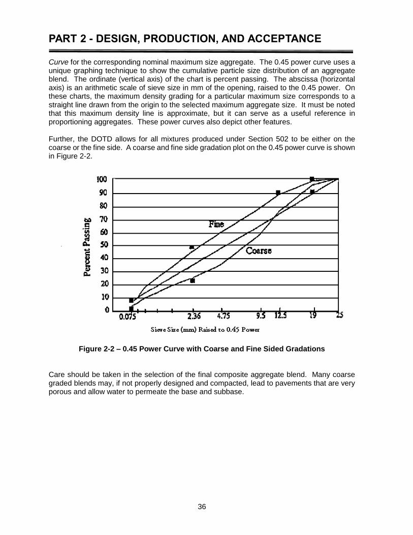
PART 2 - DESIGN, PRODUCTION, AND ACCEPTANCE
36
Curve for the corresponding nominal maximum size aggregate. The 0.45 power curve uses a unique graphing technique to show the cumulative particle size distribution of an aggregate blend. The ordinate (vertical axis) of the chart is percent passing. The abscissa (horizontal axis) is an arithmetic scale of sieve size in mm of the opening, raised to the 0.45 power. On these charts, the maximum density grading for a particular maximum size corresponds to a straight line drawn from the origin to the selected maximum aggregate size. It must be noted that this maximum density line is approximate, but it can serve as a useful reference in proportioning aggregates. These power curves also depict other features. Further, the DOTD allows for all mixtures produced under Section 502 to be either on the coarse or the fine side. A coarse and fine side gradation plot on the 0.45 power curve is shown in Figure 2-2.
Figure 2-2 – 0.45 Power Curve with Coarse and Fine Sided Gradations Care should be taken in the selection of the final composite aggregate blend. Many coarse graded blends may, if not properly designed and compacted, lead to pavements that are very porous and allow water to permeate the base and subbase.
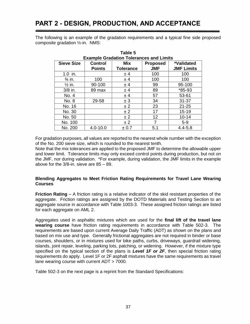
PART 2 - DESIGN, PRODUCTION, AND ACCEPTANCE
37
The following is an example of the gradation requirements and a typical fine side proposed composite gradation ½-in. NMS:
Table 5 Example Gradation Tolerances and Limits
Sieve Size Control Points
Mix Tolerance
Proposed JMF
*Validated JMF Limits
1.0 in. ± 4 100 100
¾ in. 100 ± 4 100 100
½ in. 90-100 ± 4 99 95-100
3/8 in. 89 max ± 4 89 *85-93
No. 4 ± 4 57 53-61
No. 8 29-58 ± 3 34 31-37
No. 16 ± 2 23 21-25
No. 30 ± 2 17 15-19
No. 50 ± 2 12 10-14
No. 100 ± 2 7 5-9
No. 200 4.0-10.0 ± 0.7 5.1 4.4-5.8
For gradation purposes, all values are reported to the nearest whole number with the exception of the No. 200 sieve size, which is rounded to the nearest tenth. Note that the mix tolerances are applied to the proposed JMF to determine the allowable upper and lower limit. Tolerance limits may only exceed control points during production, but not on the JMF, nor during validation. *For example, during validation, the JMF limits in the example above for the 3/8-in. sieve are 85 – 89.
Blending Aggregates to Meet Friction Rating Requirements for Travel Lane Wearing Courses Friction Rating – A friction rating is a relative indicator of the skid resistant properties of the aggregate. Friction ratings are assigned by the DOTD Materials and Testing Section to an aggregate source in accordance with Table 1003-3. These assigned friction ratings are listed for each aggregate on AML 2. Aggregates used in asphaltic mixtures which are used for the final lift of the travel lane wearing course have friction rating requirements in accordance with Table 502-3. The requirements are based upon current Average Daily Traffic (ADT) as shown on the plans and based on mix use and type. Generally frictional aggregates are not required in binder or base courses, shoulders, or in mixtures used for bike paths, curbs, driveways, guardrail widening, islands, joint repair, leveling, parking lots, patching, or widening. However, if the mixture type specified on the typical section of the plans is Level 1F or 2F, then special friction rating requirements do apply. Level 1F or 2F asphalt mixtures have the same requirements as travel lane wearing course with current ADT > 7000.
Table 502-3 on the next page is a reprint from the Standard Specifications:
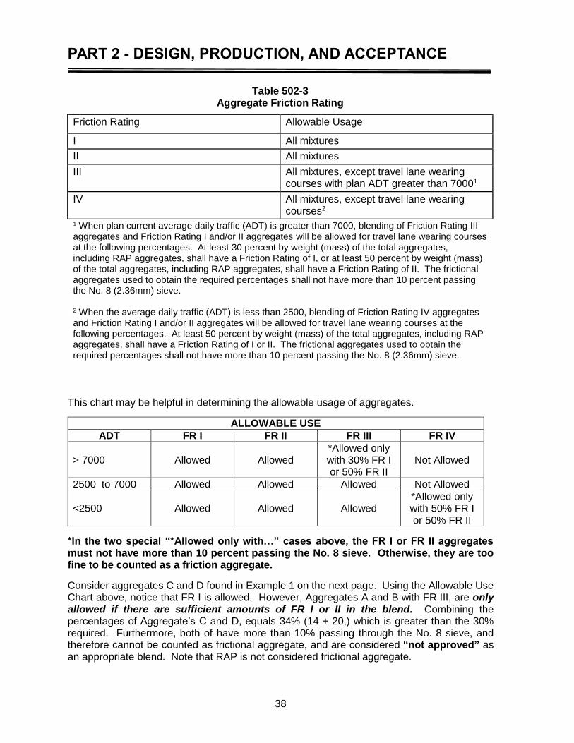
PART 2 - DESIGN, PRODUCTION, AND ACCEPTANCE
38
This chart may be helpful in determining the allowable usage of aggregates.
ALLOWABLE USE
ADT FR I FR II FR III FR IV
> 7000 Allowed Allowed *Allowed only with 30% FR I or 50% FR II
Not Allowed
2500 to 7000 Allowed Allowed Allowed Not Allowed
<2500 Allowed Allowed Allowed *Allowed only with 50% FR I or 50% FR II
*In the two special “*Allowed only with…” cases above, the FR I or FR II aggregates must not have more than 10 percent passing the No. 8 sieve. Otherwise, they are too fine to be counted as a friction aggregate.
Consider aggregates C and D found in Example 1 on the next page. Using the Allowable Use Chart above, notice that FR I is allowed. However, Aggregates A and B with FR III, are only allowed if there are sufficient amounts of FR I or II in the blend. Combining the percentages of Aggregate’s C and D, equals 34% (14 + 20,) which is greater than the 30% required. Furthermore, both of have more than 10% passing through the No. 8 sieve, and therefore cannot be counted as frictional aggregate, and are considered “not approved” as an appropriate blend. Note that RAP is not considered frictional aggregate.
Table 502-3 Aggregate Friction Rating
Friction Rating Allowable Usage
I All mixtures
II All mixtures
III All mixtures, except travel lane wearing courses with plan ADT greater than 70001
IV All mixtures, except travel lane wearing courses2
1 When plan current average daily traffic (ADT) is greater than 7000, blending of Friction Rating III aggregates and Friction Rating I and/or II aggregates will be allowed for travel lane wearing courses at the following percentages. At least 30 percent by weight (mass) of the total aggregates, including RAP aggregates, shall have a Friction Rating of I, or at least 50 percent by weight (mass) of the total aggregates, including RAP aggregates, shall have a Friction Rating of II. The frictional aggregates used to obtain the required percentages shall not have more than 10 percent passing the No. 8 (2.36mm) sieve. 2 When the average daily traffic (ADT) is less than 2500, blending of Friction Rating IV aggregates and Friction Rating I and/or II aggregates will be allowed for travel lane wearing courses at the following percentages. At least 50 percent by weight (mass) of the total aggregates, including RAP aggregates, shall have a Friction Rating of I or II. The frictional aggregates used to obtain the required percentages shall not have more than 10 percent passing the No. 8 (2.36mm) sieve.

PART 2 - DESIGN, PRODUCTION, AND ACCEPTANCE
39
EXAMPLE 1: Consider this JMF submitted for a travel lane wearing of current ADT 21,000.
AGGREGATE NAME
% of Total Aggregate on JMF
FR from QPL % passing No. 8
A - # 5 LS 22 III 0
B - # 7 LS 20 III 2
C - # 11 14 I 29
D – Black # 11 20 I 16
E – RAP 18 N/A 50
F – Coarse Sand 6 N/A 86
100 % total
EXAMPLE 2: Consider this JMF submitted for a travel lane wearing of current ADT 8200.
AGGREGATE NAME
% of Total Aggregate on JMF
FR from QPL % passing No. 8
A - # 5 SS 36 I 0
B - #7 LS 24 III 2
C - # 11 LS 25 III 29
D – Coarse Sand 15 N/A 86
100 % total
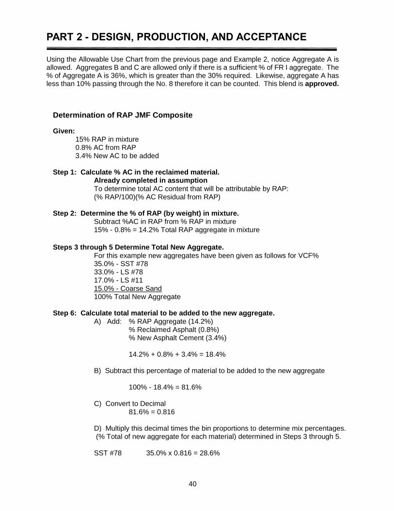
PART 2 - DESIGN, PRODUCTION, AND ACCEPTANCE
40
Using the Allowable Use Chart from the previous page and Example 2, notice Aggregate A is allowed. Aggregates B and C are allowed only if there is a sufficient % of FR I aggregate. The % of Aggregate A is 36%, which is greater than the 30% required. Likewise, aggregate A has less than 10% passing through the No. 8 therefore it can be counted. This blend is approved.
Determination of RAP JMF Composite
Given:
15% RAP in mixture
0.8% AC from RAP
3.4% New AC to be added
Step 1: Calculate % AC in the reclaimed material.
Already completed in assumption
To determine total AC content that will be attributable by RAP:
(% RAP/100)(% AC Residual from RAP) Step 2: Determine the % of RAP (by weight) in mixture. Subtract %AC in RAP from % RAP in mixture 15% - 0.8% = 14.2% Total RAP aggregate in mixture
Steps 3 through 5 Determine Total New Aggregate.
For this example new aggregates have been given as follows for VCF% 35.0% - SST #78 33.0% - LS #78 17.0% - LS #11 15.0% - Coarse Sand 100% Total New Aggregate Step 6: Calculate total material to be added to the new aggregate.
A) Add: % RAP Aggregate (14.2%) % Reclaimed Asphalt (0.8%) % New Asphalt Cement (3.4%) 14.2% + 0.8% + 3.4% = 18.4% B) Subtract this percentage of material to be added to the new aggregate 100% - 18.4% = 81.6% C) Convert to Decimal 81.6% = 0.816 D) Multiply this decimal times the bin proportions to determine mix percentages. (% Total of new aggregate for each material) determined in Steps 3 through 5. SST #78 35.0% x 0.816 = 28.6%
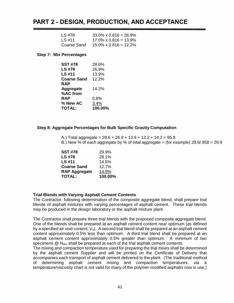
PART 2 - DESIGN, PRODUCTION, AND ACCEPTANCE
41
LS #78 33.0% x 0.816 = 26.9% LS #11 17.0% x 0.816 = 13.9% Coarse Sand 15.0% x 0.816 = 12.2% Step 7: Mix Percentages
SST #78 28.6% LS #78 26.9% LS #11 13.9% Coarse Sand 12.2%
RAP Aggregate 14.2%
%AC from RAP 0.8%
% New AC 3.4% TOTAL: 100.00% Step 8: Aggregate Percentages for Bulk Specific Gravity Computation A.) Total aggregate = 28.6 + 26.9 + 13.9 + 12.2 + 14.2 = 95.8 B.) New % of each aggregate by % of total aggregate = (for example) 28.6/.958 = 29.9 SST #78 29.9% LS #78 28.1% LS #11 14.5% Coarse Sand 12.7% RAP Aggregate 14.8% TOTAL: 100.00%
Trial Blends with Varying Asphalt Cement Contents The Contractor, following determination of the composite aggregate blend, shall prepare trial blends of asphalt mixtures with varying percentages of asphalt cement. These trial blends may be produced in the design laboratory or the asphalt mixture plant. The Contractor shall prepare three trial blends with the proposed composite aggregate blend. One of the blends shall be prepared at an asphalt cement content near optimum (as defined by a specified air void content, Va). A second trial blend shall be prepared at an asphalt cement content approximately 0.5% less than optimum. A third trial blend shall be prepared at an asphalt cement content approximately 0.5% greater than optimum. A minimum of two specimens @ Ndes shall be prepared at each of the trial asphalt cement contents. The mixing and compaction temperature used for preparing the trial mixes shall be determined by the asphalt cement Supplier and will be printed on the Certificate of Delivery that accompanies each transport of asphalt cement delivered to the plant. (The traditional method of determining asphalt cement mixing and compaction temperatures, via a temperature/viscosity chart is not valid for many of the polymer-modified asphalts now in use.)
PART 2 - DESIGN, PRODUCTION, AND ACCEPTANCE
42
Unless procedures require otherwise, the laboratory produced mix shall be cured 2 hours and plant produced mix shall be cured 1 hour at the compaction temperature (±10°F). When the aggregate water absorption is > 2%, the oven aging time for plant-produced mix shall be 2 hours. Once the trial blends have been prepared, specimens (briquettes) shall be tested for the following:
1. Bulk Specific Gravity, Gmb at Ndesign 2. Air Voids, Va at Ndesign 3. Voids in Mineral Aggregate, VMA at Ndesign 4. Voids Filled with Asphalt, VFA at Ndesign 5. % Gmm at Ninitial 6. % Gmm at Ndesign 7. % Gmm at Nmax
In addition, a loose mix sample from each trial blend asphalt cement content shall be prepared and tested for maximum theoretical specific gravity, Gmm (Rice Gravity) using DOTD TR 327. For laboratory produced trial blends, the mixture, when tested for Gmm, shall be cured at compaction temperature for approximately 2 hours prior to specimen preparation. Plant produced trial blends require one (1) hour curing or aging period. The Gmm test values for the two specimens at each asphalt content shall be averaged to report a single value. For design purposes, the Contractor may elect to prepare one loose mix near optimum AC content and calculate the high and low AC content Gmm. LaPave, the current DOTD design submittal spreadsheet uses this method. The verification blend will require two Gmm tests averaged to report a single value. After determining the optimum AC content and performing volumetric testing, the Contractor will establish an AC Correction Factor for the proposed JMF according to TR 323. All JMF AC Correction Factors are subject to verification by the DLE. Mineral aggregate is porous and can absorb water and asphalt to a variable degree. Furthermore, the ratio of water to asphalt absorption varies with each aggregate. The three methods of measuring aggregate specific gravity consider these variations. The methods are bulk, apparent, and effective specific gravities. The differences among the specific gravities come from the different definitions of aggregate volume. The Department, for use when analyzing and documenting Superpave hot-mix asphalt mixtures, adopts the following definitions and nomenclature: Bulk Specific Gravity, Gsb – The ratio of the weight in air of a unit volume of a permeable material (including both permeable and impermeable voids normal for the material) at a stated temperature to the weight in air of equal density of an equal volume of gas-free distilled water at a stated temperature. See Figure 2-3.
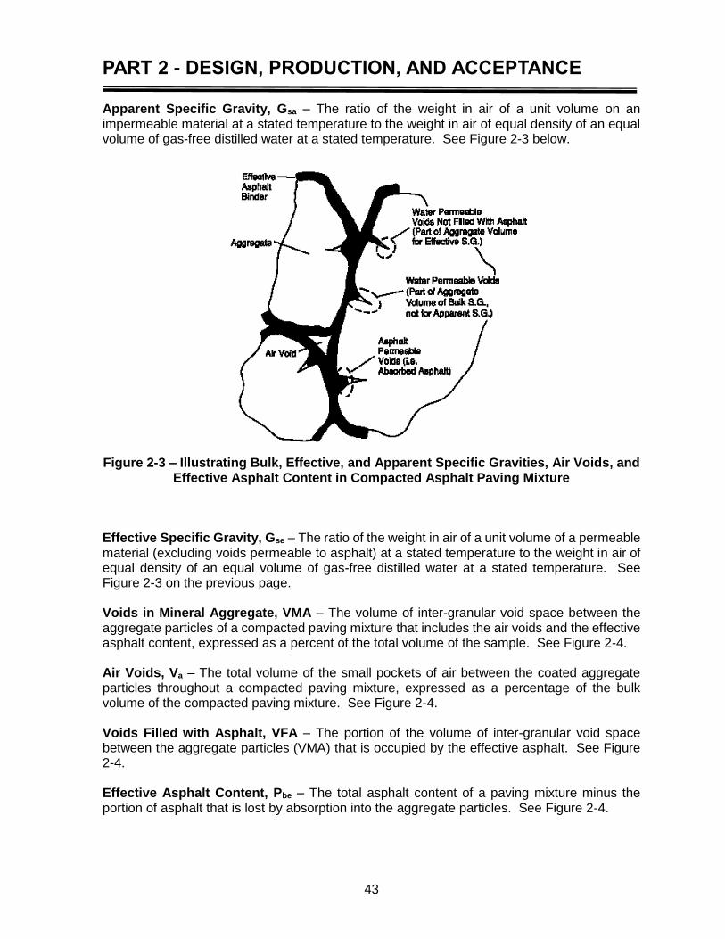
PART 2 - DESIGN, PRODUCTION, AND ACCEPTANCE
43
Apparent Specific Gravity, Gsa – The ratio of the weight in air of a unit volume on an impermeable material at a stated temperature to the weight in air of equal density of an equal volume of gas-free distilled water at a stated temperature. See Figure 2-3 below.
Figure 2-3 – Illustrating Bulk, Effective, and Apparent Specific Gravities, Air Voids, and Effective Asphalt Content in Compacted Asphalt Paving Mixture
Effective Specific Gravity, Gse – The ratio of the weight in air of a unit volume of a permeable material (excluding voids permeable to asphalt) at a stated temperature to the weight in air of equal density of an equal volume of gas-free distilled water at a stated temperature. See Figure 2-3 on the previous page. Voids in Mineral Aggregate, VMA – The volume of inter-granular void space between the aggregate particles of a compacted paving mixture that includes the air voids and the effective asphalt content, expressed as a percent of the total volume of the sample. See Figure 2-4. Air Voids, Va – The total volume of the small pockets of air between the coated aggregate particles throughout a compacted paving mixture, expressed as a percentage of the bulk volume of the compacted paving mixture. See Figure 2-4. Voids Filled with Asphalt, VFA – The portion of the volume of inter-granular void space between the aggregate particles (VMA) that is occupied by the effective asphalt. See Figure 2-4. Effective Asphalt Content, Pbe – The total asphalt content of a paving mixture minus the portion of asphalt that is lost by absorption into the aggregate particles. See Figure 2-4.
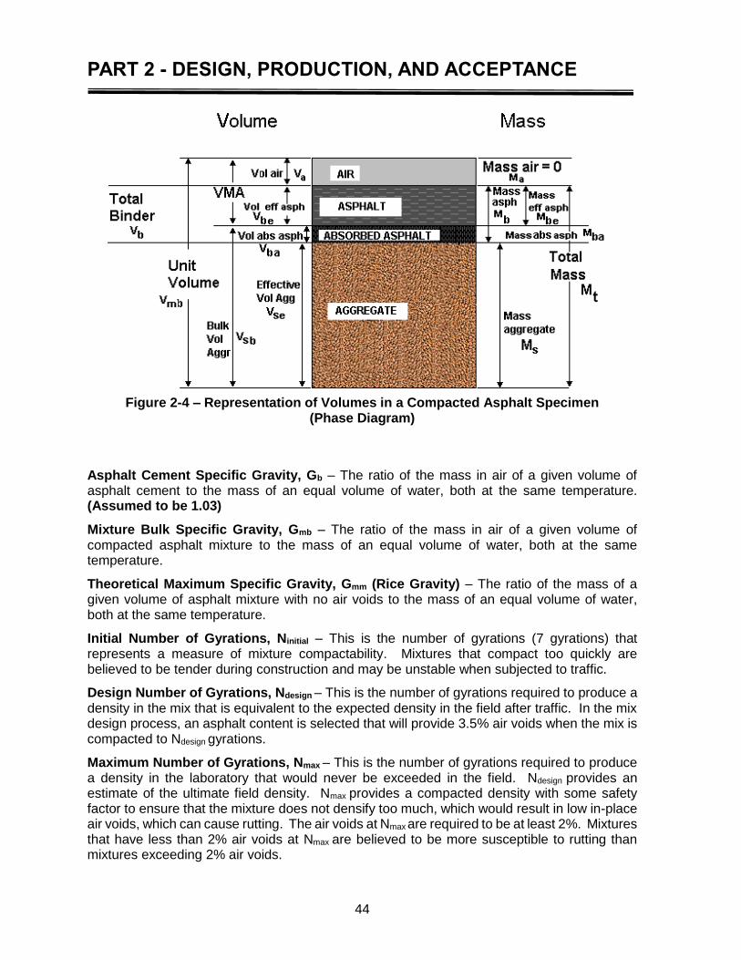
PART 2 - DESIGN, PRODUCTION, AND ACCEPTANCE
44
Figure 2-4 – Representation of Volumes in a Compacted Asphalt Specimen
(Phase Diagram)
Asphalt Cement Specific Gravity, Gb – The ratio of the mass in air of a given volume of asphalt cement to the mass of an equal volume of water, both at the same temperature. (Assumed to be 1.03)
Mixture Bulk Specific Gravity, Gmb – The ratio of the mass in air of a given volume of compacted asphalt mixture to the mass of an equal volume of water, both at the same temperature.
Theoretical Maximum Specific Gravity, Gmm (Rice Gravity) – The ratio of the mass of a given volume of asphalt mixture with no air voids to the mass of an equal volume of water, both at the same temperature.
Initial Number of Gyrations, Ninitial – This is the number of gyrations (7 gyrations) that represents a measure of mixture compactability. Mixtures that compact too quickly are believed to be tender during construction and may be unstable when subjected to traffic.
Design Number of Gyrations, Ndesign – This is the number of gyrations required to produce a density in the mix that is equivalent to the expected density in the field after traffic. In the mix design process, an asphalt content is selected that will provide 3.5% air voids when the mix is compacted to Ndesign gyrations.
Maximum Number of Gyrations, Nmax – This is the number of gyrations required to produce a density in the laboratory that would never be exceeded in the field. Ndesign provides an estimate of the ultimate field density. Nmax provides a compacted density with some safety factor to ensure that the mixture does not densify too much, which would result in low in-place air voids, which can cause rutting. The air voids at Nmax are required to be at least 2%. Mixtures that have less than 2% air voids at Nmax are believed to be more susceptible to rutting than mixtures exceeding 2% air voids.
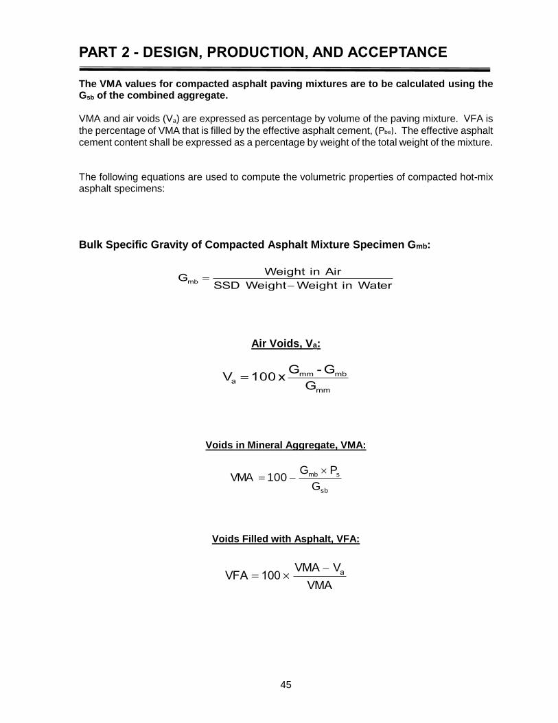
PART 2 - DESIGN, PRODUCTION, AND ACCEPTANCE
45
The VMA values for compacted asphalt paving mixtures are to be calculated using the Gsb of the combined aggregate. VMA and air voids (Va) are expressed as percentage by volume of the paving mixture. VFA is
the percentage of VMA that is filled by the effective asphalt cement, (Pbe). The effective asphalt cement content shall be expressed as a percentage by weight of the total weight of the mixture. The following equations are used to compute the volumetric properties of compacted hot-mix asphalt specimens:
Bulk Specific Gravity of Compacted Asphalt Mixture Specimen Gmb:
Water in WeightWeight SSD
Airin WeightGmb
Air Voids, Va:
mm
mbmma
G
G-Gx100V
Voids in Mineral Aggregate, VMA:
sb
smb
G
PG100VMA
Voids Filled with Asphalt, VFA:
VMA
VVMA100VFA a

PART 2 - DESIGN, PRODUCTION, AND ACCEPTANCE
46
Effective Specific Gravity, Gse:
b
b
mm
bse
G
P
G
100
P100G
Percent Absorbed Asphalt, Pba:
sesb
sbsebba
GG
GGG100P
Percent Effective Asphalt Cement, Pbe:
100
PxPPP sba
bbe
Dust to Asphalt Ratio, D/P or P200/Pbe:
be
200
P
PRatio Dust
The asphalt mixture volumetric analysis results for the trial blends shall be documented in DOTD approved software. The following relationships, as determined from these equations, shall also be plotted on an approved graph or the form to show the Optimum Asphalt Cement Content - Summary of Test Properties.
1. Air Void (Va) versus asphalt content 2. Voids in Mineral Aggregate (VMA) versus asphalt content 3. Voids Filled with Asphalt (VFA) versus asphalt content
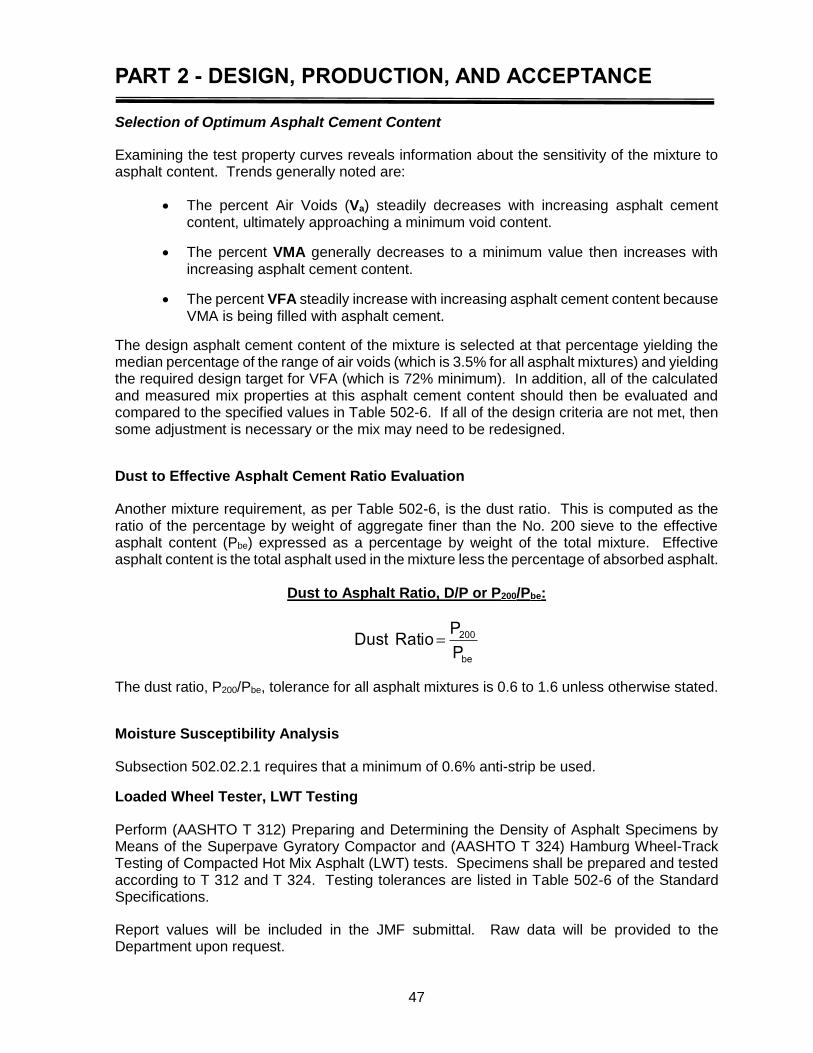
PART 2 - DESIGN, PRODUCTION, AND ACCEPTANCE
47
Selection of Optimum Asphalt Cement Content
Examining the test property curves reveals information about the sensitivity of the mixture to asphalt content. Trends generally noted are:
The percent Air Voids (Va) steadily decreases with increasing asphalt cement content, ultimately approaching a minimum void content.
The percent VMA generally decreases to a minimum value then increases with increasing asphalt cement content.
The percent VFA steadily increase with increasing asphalt cement content because VMA is being filled with asphalt cement.
The design asphalt cement content of the mixture is selected at that percentage yielding the median percentage of the range of air voids (which is 3.5% for all asphalt mixtures) and yielding the required design target for VFA (which is 72% minimum). In addition, all of the calculated and measured mix properties at this asphalt cement content should then be evaluated and compared to the specified values in Table 502-6. If all of the design criteria are not met, then some adjustment is necessary or the mix may need to be redesigned.
Dust to Effective Asphalt Cement Ratio Evaluation
Another mixture requirement, as per Table 502-6, is the dust ratio. This is computed as the ratio of the percentage by weight of aggregate finer than the No. 200 sieve to the effective asphalt content (Pbe) expressed as a percentage by weight of the total mixture. Effective asphalt content is the total asphalt used in the mixture less the percentage of absorbed asphalt.
Dust to Asphalt Ratio, D/P or P200/Pbe:
be
200
P
PRatio Dust
The dust ratio, P200/Pbe, tolerance for all asphalt mixtures is 0.6 to 1.6 unless otherwise stated.
Moisture Susceptibility Analysis
Subsection 502.02.2.1 requires that a minimum of 0.6% anti-strip be used.
Loaded Wheel Tester, LWT Testing
Perform (AASHTO T 312) Preparing and Determining the Density of Asphalt Specimens by Means of the Superpave Gyratory Compactor and (AASHTO T 324) Hamburg Wheel-Track Testing of Compacted Hot Mix Asphalt (LWT) tests. Specimens shall be prepared and tested according to T 312 and T 324. Testing tolerances are listed in Table 502-6 of the Standard Specifications.
Report values will be included in the JMF submittal. Raw data will be provided to the Department upon request.

PART 2 - DESIGN, PRODUCTION, AND ACCEPTANCE
48
Semi Circular Bend Test (SCB) Perform according to TR 330. The Contractor will perform SCB testing for design. The SCB test for design submittal may be witnessed by a DOTD employee at the request of the DLE. The Contractor will coordinate with the DLE for an employee to be present for testing. The Contractor will submit required data with the JMF proposal. SCB will not be required for leveling or minor mixes. Any mix that is under traffic will be subject to SCB testing.
Tensile Strength Ratio, (TSR), (Lottman) (Minor Mixes) (Optional) To complete the design process for minor mixes, the Contractor may, in lieu of LWT, perform the moisture sensitivity test (DOTD TR 322) to evaluate the proposed hot-mix asphalt blend for stripping. This test identifies whether a combination of asphalt cement and aggregate is moisture susceptible. Results will be reported on the TSR Form (in LaPave) and forwarded to the DLE with the JMF proposal. When the results are less than 80%, no further production for that job mix formula or any proposed job mix formula substituted for that mix type will be accepted on any DOTD project having DOTD TR 322 requirements until a passing plant-produced Tensile Strength Ratio (TSR) value is verified by the Department.
SMA Design Criteria
SMA is hot-mix asphalt consisting of two parts: a coarse aggregate skeleton and binder rich mastic. SMA mix design is to have a gap-graded stone-on-stone coarse graded skeleton. SMA shall have a minimum 6.0% PG 76-22m or PG 82-22rm AC in design and production. VMA shall be a minimum of 16.0% in design and production. Mineral fillers and/or fibers may be used to help to minimize draindown. Draindown shall not exceed 0.3% in design or production. Design criteria shall meet specifications in Table 502-6 of the Standard Specifications. RAP is not allowed in SMA. SMA will not have a maximum VFA limit.
SMA shall be designed according to the Superpave method utilizing these design steps:
Select proper aggregate materials in accordance to section 1003.06 of the Standard Specifications
Determine an aggregate gradation yielding stone-on-stone contact meeting VCA requirements as outlined below
Ensure the chosen gradation meets or exceeds minimum VMA requirements
Choose an asphalt content that provides the desired air void level
Evaluate the moisture susceptibility and asphalt cement draindown
Flat and Elongated percentages shall conform to footnotes 2 and 3 in Table 1003-2 of the Standard Specifications
VCA (Voids in the Coarse Aggregate) determination (AASHTO R46), Designing Stone Matrix Asphalt
(AASHTO T 19), Bulk Density (“Unit Weight”)
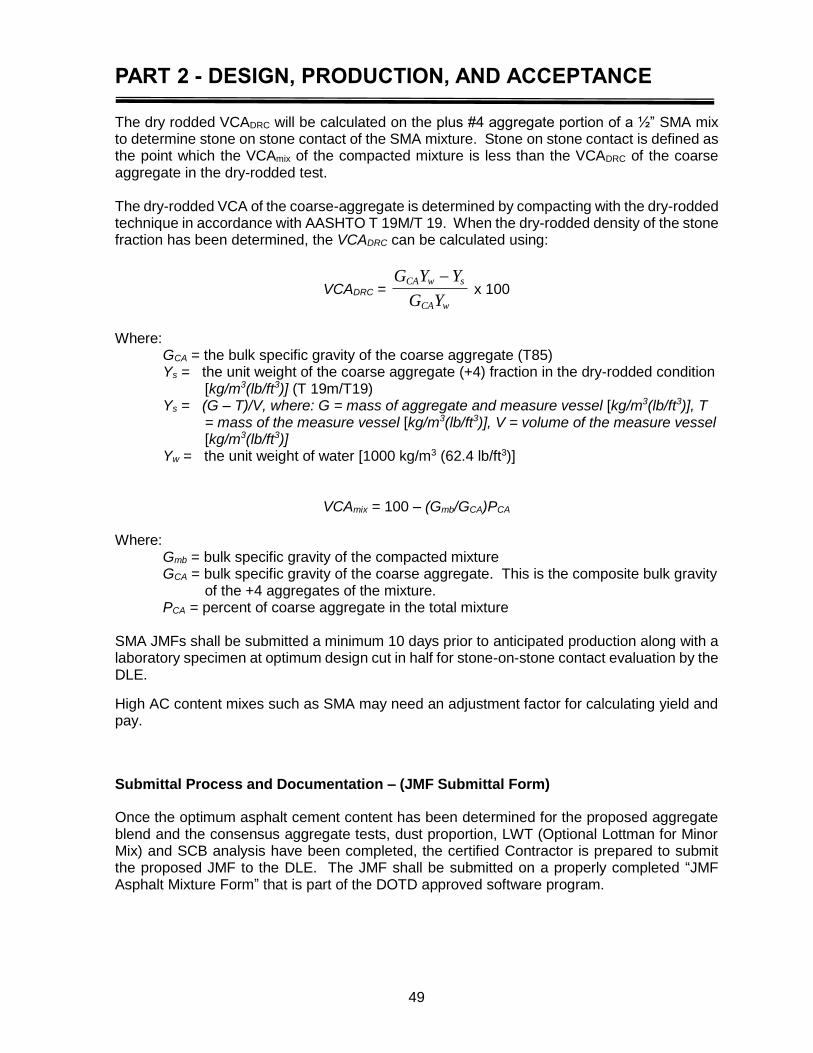
PART 2 - DESIGN, PRODUCTION, AND ACCEPTANCE
49
The dry rodded VCADRC will be calculated on the plus #4 aggregate portion of a ½” SMA mix to determine stone on stone contact of the SMA mixture. Stone on stone contact is defined as the point which the VCAmix of the compacted mixture is less than the VCADRC of the coarse aggregate in the dry-rodded test. The dry-rodded VCA of the coarse-aggregate is determined by compacting with the dry-rodded technique in accordance with AASHTO T 19M/T 19. When the dry-rodded density of the stone fraction has been determined, the VCADRC can be calculated using:
VCADRC = G Y Y
G Y
CA w s
CA w
x 100
Where:
GCA = the bulk specific gravity of the coarse aggregate (T85) Ys = the unit weight of the coarse aggregate (+4) fraction in the dry-rodded condition
[kg/m3(lb/ft3)] (T 19m/T19) Ys = (G – T)/V, where: G = mass of aggregate and measure vessel [kg/m3(lb/ft3)], T
= mass of the measure vessel [kg/m3(lb/ft3)], V = volume of the measure vessel [kg/m3(lb/ft3)]
Yw = the unit weight of water [1000 kg/m3 (62.4 lb/ft3)]
VCAmix = 100 – (Gmb/GCA)PCA Where:
Gmb = bulk specific gravity of the compacted mixture GCA = bulk specific gravity of the coarse aggregate. This is the composite bulk gravity
of the +4 aggregates of the mixture. PCA = percent of coarse aggregate in the total mixture
SMA JMFs shall be submitted a minimum 10 days prior to anticipated production along with a laboratory specimen at optimum design cut in half for stone-on-stone contact evaluation by the DLE.
High AC content mixes such as SMA may need an adjustment factor for calculating yield and pay.
Submittal Process and Documentation – (JMF Submittal Form)
Once the optimum asphalt cement content has been determined for the proposed aggregate blend and the consensus aggregate tests, dust proportion, LWT (Optional Lottman for Minor Mix) and SCB analysis have been completed, the certified Contractor is prepared to submit the proposed JMF to the DLE. The JMF shall be submitted on a properly completed “JMF Asphalt Mixture Form” that is part of the DOTD approved software program.
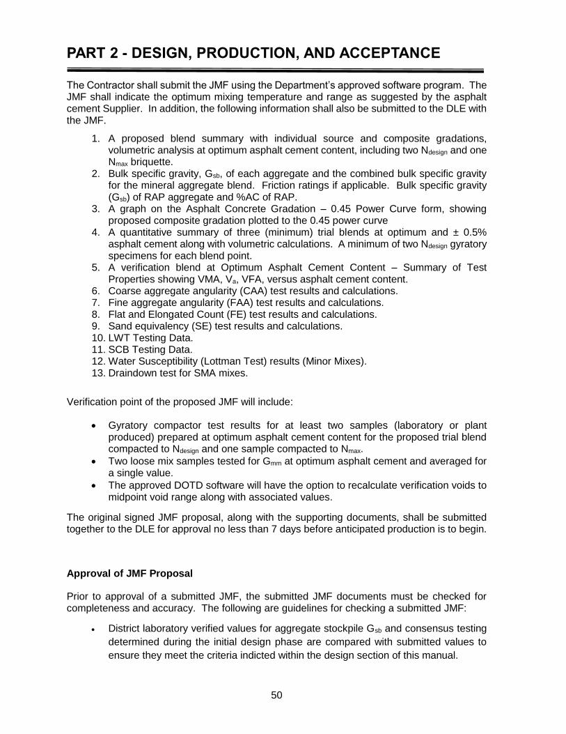
PART 2 - DESIGN, PRODUCTION, AND ACCEPTANCE
50
The Contractor shall submit the JMF using the Department’s approved software program. The JMF shall indicate the optimum mixing temperature and range as suggested by the asphalt cement Supplier. In addition, the following information shall also be submitted to the DLE with the JMF.
1. A proposed blend summary with individual source and composite gradations, volumetric analysis at optimum asphalt cement content, including two Ndesign and one Nmax briquette.
2. Bulk specific gravity, Gsb, of each aggregate and the combined bulk specific gravity for the mineral aggregate blend. Friction ratings if applicable. Bulk specific gravity (Gsb) of RAP aggregate and %AC of RAP.
3. A graph on the Asphalt Concrete Gradation – 0.45 Power Curve form, showing proposed composite gradation plotted to the 0.45 power curve
4. A quantitative summary of three (minimum) trial blends at optimum and ± 0.5% asphalt cement along with volumetric calculations. A minimum of two Ndesign gyratory specimens for each blend point.
5. A verification blend at Optimum Asphalt Cement Content – Summary of Test Properties showing VMA, Va, VFA, versus asphalt cement content.
6. Coarse aggregate angularity (CAA) test results and calculations. 7. Fine aggregate angularity (FAA) test results and calculations. 8. Flat and Elongated Count (FE) test results and calculations. 9. Sand equivalency (SE) test results and calculations. 10. LWT Testing Data. 11. SCB Testing Data. 12. Water Susceptibility (Lottman Test) results (Minor Mixes). 13. Draindown test for SMA mixes.
Verification point of the proposed JMF will include:
Gyratory compactor test results for at least two samples (laboratory or plant produced) prepared at optimum asphalt cement content for the proposed trial blend compacted to Ndesign and one sample compacted to Nmax.
Two loose mix samples tested for Gmm at optimum asphalt cement and averaged for a single value.
The approved DOTD software will have the option to recalculate verification voids to midpoint void range along with associated values.
The original signed JMF proposal, along with the supporting documents, shall be submitted together to the DLE for approval no less than 7 days before anticipated production is to begin.
Approval of JMF Proposal
Prior to approval of a submitted JMF, the submitted JMF documents must be checked for completeness and accuracy. The following are guidelines for checking a submitted JMF:
District laboratory verified values for aggregate stockpile Gsb and consensus testing
determined during the initial design phase are compared with submitted values to
ensure they meet the criteria indicted within the design section of this manual.

PART 2 - DESIGN, PRODUCTION, AND ACCEPTANCE
51
Design specification criteria: o Gmm o Gmb o Va o VMA o VFA (Design at 72%) o LWT (Rut Testing) Data o SCB (Semi Circular Bend) test results o Water Susceptibility (Modified Lottman) (Minor Mixes) o Draindown for SMA
Upon approval of the proposed JMF, the DLE will give it a numerical identification (the JMF Sequence Number). This identifying code must be clearly written, typed, or printed on the JMF proposal form and all supporting documentation.
Upon approval of the JMF, the DLE will electronically approve or sign in the “Proposal Approved” section of the document and date it. The district laboratory will send an approved JMF to the Contractor and Project Engineer’s office.
Validation of JMF Proposal
Once the DLE has approved the JMF for validation, the plant may begin producing mixtures for the Department in accordance with the JMF. However, before the validation process begins for the approved JMF proposal, the Project Engineer in charge of the project must verify that the mix type and project specifications for the project(s) receiving the mix are the same as the proposed mix design and appropriate for the application. The first day’s production or a maximum of 2000 tons of mix shall be used to validate a new JMF. The Contractor and the Department using the stratified random sampling approach shall jointly take and test five samples, one per validation sublot, during the validation lot. Validation of a mainline JMF requires a minimum of 1000 tons. Multiple day validation is acceptable. At the discretion of the DLE, a mix may be validated on three test or five test, (n=3 or n=5). The Contractor, with the approval of the Department, may exclude any one irregular validation sublot test set representing any one validation sublot tested from the validation analysis provided the validation is adjusted to meet the minimum number of samples. Pay on the Validation roadway lot will be in accordance with acceptance pay parameters, based on core density. There is a separate roadway lot for validation. The validation lot pay will be based on one roadway core per sublot of the validation. PWL requirements will be the same as a regular roadway lot.
NOTE: The DLE or their representative must approve the proposed JMF before any mixture can be produced for the Department.
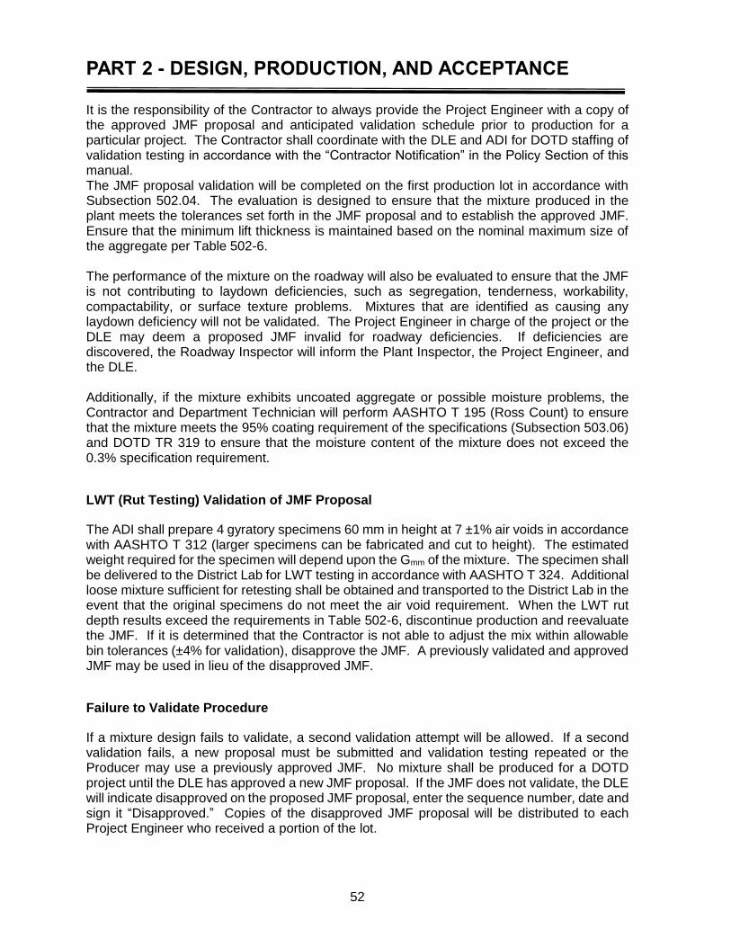
PART 2 - DESIGN, PRODUCTION, AND ACCEPTANCE
52
It is the responsibility of the Contractor to always provide the Project Engineer with a copy of the approved JMF proposal and anticipated validation schedule prior to production for a particular project. The Contractor shall coordinate with the DLE and ADI for DOTD staffing of validation testing in accordance with the “Contractor Notification” in the Policy Section of this manual. The JMF proposal validation will be completed on the first production lot in accordance with Subsection 502.04. The evaluation is designed to ensure that the mixture produced in the plant meets the tolerances set forth in the JMF proposal and to establish the approved JMF. Ensure that the minimum lift thickness is maintained based on the nominal maximum size of the aggregate per Table 502-6. The performance of the mixture on the roadway will also be evaluated to ensure that the JMF is not contributing to laydown deficiencies, such as segregation, tenderness, workability, compactability, or surface texture problems. Mixtures that are identified as causing any laydown deficiency will not be validated. The Project Engineer in charge of the project or the DLE may deem a proposed JMF invalid for roadway deficiencies. If deficiencies are discovered, the Roadway Inspector will inform the Plant Inspector, the Project Engineer, and the DLE. Additionally, if the mixture exhibits uncoated aggregate or possible moisture problems, the Contractor and Department Technician will perform AASHTO T 195 (Ross Count) to ensure that the mixture meets the 95% coating requirement of the specifications (Subsection 503.06) and DOTD TR 319 to ensure that the moisture content of the mixture does not exceed the 0.3% specification requirement.
LWT (Rut Testing) Validation of JMF Proposal
The ADI shall prepare 4 gyratory specimens 60 mm in height at 7 ±1% air voids in accordance with AASHTO T 312 (larger specimens can be fabricated and cut to height). The estimated weight required for the specimen will depend upon the Gmm of the mixture. The specimen shall be delivered to the District Lab for LWT testing in accordance with AASHTO T 324. Additional loose mixture sufficient for retesting shall be obtained and transported to the District Lab in the event that the original specimens do not meet the air void requirement. When the LWT rut depth results exceed the requirements in Table 502-6, discontinue production and reevaluate the JMF. If it is determined that the Contractor is not able to adjust the mix within allowable bin tolerances (±4% for validation), disapprove the JMF. A previously validated and approved JMF may be used in lieu of the disapproved JMF.
Failure to Validate Procedure
If a mixture design fails to validate, a second validation attempt will be allowed. If a second validation fails, a new proposal must be submitted and validation testing repeated or the Producer may use a previously approved JMF. No mixture shall be produced for a DOTD project until the DLE has approved a new JMF proposal. If the JMF does not validate, the DLE will indicate disapproved on the proposed JMF proposal, enter the sequence number, date and sign it “Disapproved.” Copies of the disapproved JMF proposal will be distributed to each Project Engineer who received a portion of the lot.
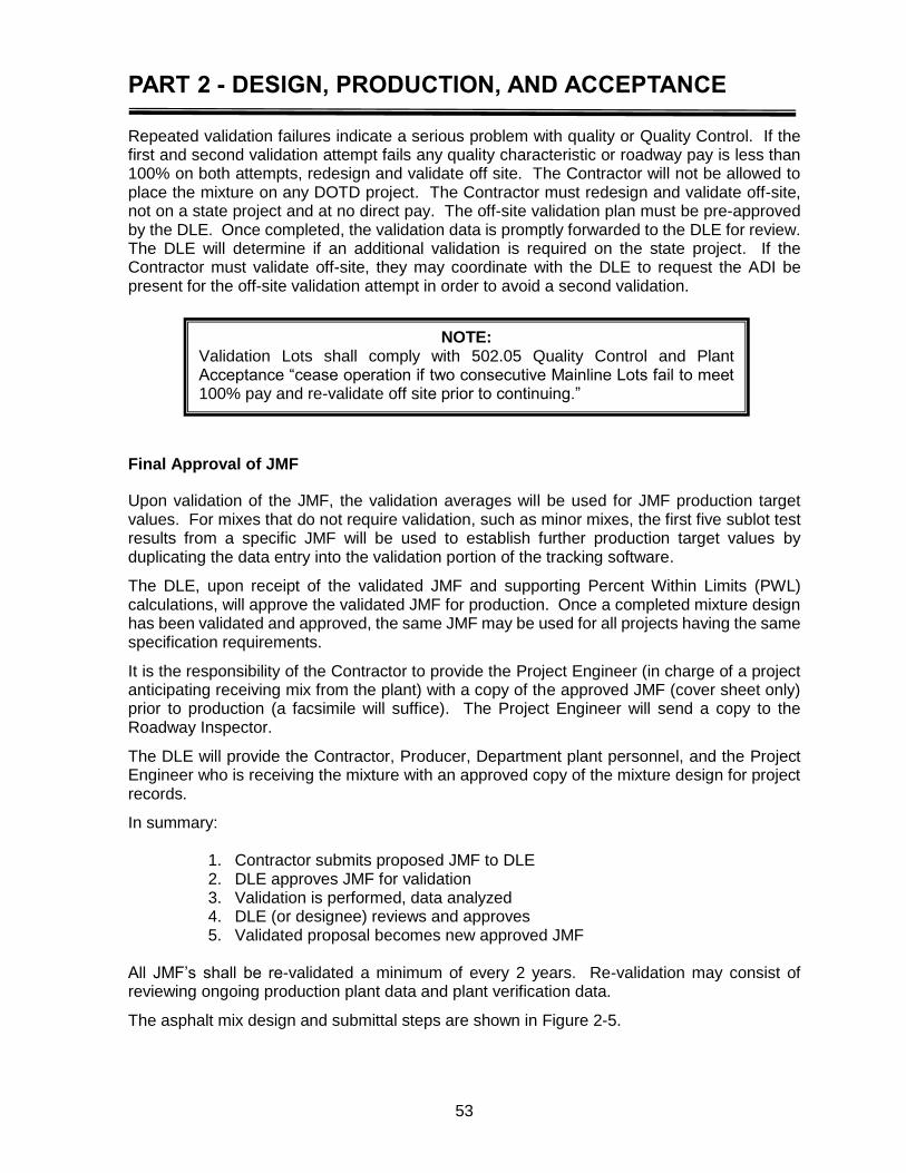
PART 2 - DESIGN, PRODUCTION, AND ACCEPTANCE
53
Repeated validation failures indicate a serious problem with quality or Quality Control. If the first and second validation attempt fails any quality characteristic or roadway pay is less than 100% on both attempts, redesign and validate off site. The Contractor will not be allowed to place the mixture on any DOTD project. The Contractor must redesign and validate off-site, not on a state project and at no direct pay. The off-site validation plan must be pre-approved by the DLE. Once completed, the validation data is promptly forwarded to the DLE for review. The DLE will determine if an additional validation is required on the state project. If the Contractor must validate off-site, they may coordinate with the DLE to request the ADI be present for the off-site validation attempt in order to avoid a second validation.
Final Approval of JMF
Upon validation of the JMF, the validation averages will be used for JMF production target values. For mixes that do not require validation, such as minor mixes, the first five sublot test results from a specific JMF will be used to establish further production target values by duplicating the data entry into the validation portion of the tracking software.
The DLE, upon receipt of the validated JMF and supporting Percent Within Limits (PWL) calculations, will approve the validated JMF for production. Once a completed mixture design has been validated and approved, the same JMF may be used for all projects having the same specification requirements.
It is the responsibility of the Contractor to provide the Project Engineer (in charge of a project anticipating receiving mix from the plant) with a copy of the approved JMF (cover sheet only) prior to production (a facsimile will suffice). The Project Engineer will send a copy to the Roadway Inspector.
The DLE will provide the Contractor, Producer, Department plant personnel, and the Project Engineer who is receiving the mixture with an approved copy of the mixture design for project records.
In summary:
1. Contractor submits proposed JMF to DLE 2. DLE approves JMF for validation 3. Validation is performed, data analyzed 4. DLE (or designee) reviews and approves 5. Validated proposal becomes new approved JMF
All JMF’s shall be re-validated a minimum of every 2 years. Re-validation may consist of reviewing ongoing production plant data and plant verification data.
The asphalt mix design and submittal steps are shown in Figure 2-5.
NOTE: Validation Lots shall comply with 502.05 Quality Control and Plant Acceptance “cease operation if two consecutive Mainline Lots fail to meet 100% pay and re-validate off site prior to continuing.”
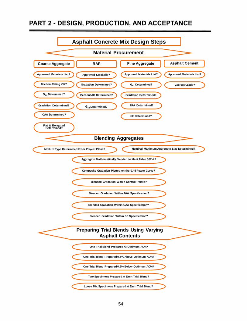
PART 2 - DESIGN, PRODUCTION, AND ACCEPTANCE
54
Asphalt Concrete Mix Design Steps
Material Procurement
Coarse Aggregate Fine AggregateRAP Asphalt Cement
Approved Stockpile?Approved Materials List?
Friction Rating OK?
Gsb Determined?
CAA Determined?
Flat & Elongated Determined?
Gradation Determined?
Gradation Determined?
Percent AC Determined?
Approved Materials List?
Gsb Determined?
Gradation Determined?
FAA Determined?
SE Determined?
Approved Materials List?
Correct Grade?
Mixture Type Determined From Project Plans?
Blending Aggregates
Nominal Maximum Aggregate Size Determined?
Aggregate Mathematically Blended to Meet Table 502-4?
Composite Gradation Plotted on the 0.45 Power Curve?
Blended Gradation Within Control Points?
Blended Gradation Within FAA Specification?
Blended Gradation Within CAA Specification?
Blended Gradation Within SE Specification?
One Trial Blend Prepared At Optimum AC%?
One Trial Blend Prepared 0.5% Above Optimum AC%?
One Trial Blend Prepared 0.5% Below Optimum AC%?
Preparing Trial Blends Using Varying
Asphalt Contents
Two Specimens Prepared at Each Trial Blend?
Loose Mix Specimens Prepared at Each Trial Blend?
Gsb Determined?
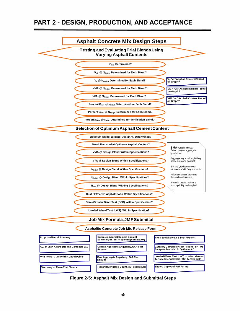
PART 2 - DESIGN, PRODUCTION, AND ACCEPTANCE
55
Figure 2-5: Asphalt Mix Design and Submittal Steps
Testing and Evaluating Trial Blends Using Varying Asphalt Contents
Gmm Determined?
Gmb @ Ndesign Determined for Each Blend?
Va @ Ndesign Determined for Each Blend?
VMA @ Design Blend Within Specifications?
VFA @ Design Blend Within Specifications?
Ninitial @ Design Blend Within Specifications?
Ndesign @ Design Blend Within Specifications?
Nmax @ Design Blend Withing Specifications?
Selection of Optimum Asphalt Cement Content
Blend Prepared at Optimum Asphalt Content?
Va "vs" Asphalt Content Plotted on Graph?
VMA "vs" Asphalt Content Plotted on Graph?
VFA "vs" Asphalt Content Plotted on Graph?
Dust / Effective Asphalt Ratio Within Specifications?
Semi-Circular Bend Test (SCB) Within Specification?
Loaded Wheel Test (LWT) Within Specification?
VMA @ Ndesign Determined for Each Blend?
VFA @ Ndesign Determined for Each Blend?
Percent Gmm @ Ninitial Determined for Each Blend?
Percent Gmm @ Ndesign Determined for Each Blend?
Percent Gmm @ Nmax Determined for Verification Blend?
Asphalt Concrete Mix Design Steps
Job Mix Formula, JMF Submittal
Asphaltic Concrete Job Mix Release Form
Proposed Blend Summary
Gsb of Each Aggregate and Combined Gsb
0.45 Power Curve With Control Points
Summary of Three Trial Blends
Optimum Asphalt Cement Content Summary of Test Properties (Verification)
Coarse Aggregate Angularity, CAA Test Results
Fine Aggregate Angularity, FAA Test Results
Flat and Elongated Count, FE Test Results
Sand Equivilancy, SE Test Results
Gyratory Compactor Test Results For Two Samples Prepared At Optimum AC
Loaded Wheet Test (LWT) or when allowed,Tensile Strength Ratio, TSR Test Results
Signed Copies of JMF Forms
Optimum Blend Yeilding Design Va Determined?
SMA requirements:Select proper aggregate
gradation
Aggregate gradation yielding stone on stone contact
Ensure gradation meets minimum VMA Requirements
Asphalt content provides desired void content
The mix meets moisture
susceptibility and asphalt

PART 2 - DESIGN, PRODUCTION, AND ACCEPTANCE
56
PART 2 - DESIGN, PRODUCTION, AND ACCEPTANCE
57
Definition of a Lot
1 Lot will be 5,000 tons consisting of 5 – 1,000 ton sublots. For Quality Control and contractor Acceptance testing, obtain a mixture sample from each 1000 tons of plant-produced mixture sublot using a stratified random sampling approach. A representative sample shall be sufficient to provide enough mixture for all Quality Control testing. A lot is a segment of continuous production of asphalt concrete mixture from the same job mix formula produced for the Department at an individual plant. The plant lot and sublots will be used for quality assurance purposes without pay adjustments. Plant lots will be specific to projects. Lot designation shall be reported on each haul ticket delivered to each state project. The Contractor shall maintain a “Field Book” in the plant lab to track the production of Plant Lots. Minimum information to be maintained:
Date
State Project mix shipped to
DOTD JMF sequence number and Lot No.
Tons shipped
Accumulated tons of the Lot
Remarks
Initials of person entering information
AC type
A JMF that is originally submitted as a Level 1 wearing course could also meet specifications for a Level A. If a district wishes to track the performance of the aggregate structure to compare to the original submittal, a modified sequence number could be used. An example would be: JMF 101 for the original W.C. submittal and JMF 101(67) for submittal as a Level A. The (67) denotes that the JMF contains PG67-22. It may take multiple days to complete a lot in which case the Contractor shall perform and report multiple Quality Control test on an individual lot. When production is ≥ 100 tons per day per “Mainline” JMF, Contractor QC testing shall be performed and reported into the DOTD tracking software in addition to the Contractor Acceptance test for each lot. A standard lot is five 1000-ton sublots for a total of 5000 tons; minor adjustments will be made in the 5000-ton lot size to accommodate hauling unit capacity. When the total lot quantity is expended in the partial load of a truck, the full legal load of the truck will be included in the lot. For example, if 4988 tons of asphalt mixture are produced and sent to a project and the next truck hauls 24 tons, the actual lot size will be 5012 tons (4988 + 24).
Roadway Lot
A lot shall be tracked at 5000 tons from the plant. Either mainline asphalt mix, minor asphalt mix use or a combination use of both from the same JMF. Roadway lot numbers will be the same as the plant lot number.
PART 2 - DESIGN, PRODUCTION, AND ACCEPTANCE
58
The wearing course is defined as the final lift placed. The binder course is defined as the lift placed prior to the final lift. When 501 mixtures are placed over 502 they are defined as “Finish Courses.” Mainline mixtures include wearing, binder, and base courses for travel lanes, ramps greater than 300 ft., interstate acceleration/deceleration lanes, center turn lanes, and the two center lanes for airports.
Minor Mix
Minor mixes include mixture used for bike paths, crossovers, curbs, detour roads, driveways, guardrail widening, islands, joint repair, leveling, medians, parking lots, shoulders, turnouts, ramps less than or equal to 300 ft., patching, widening, miscellaneous handwork, and any other mixture that is not mainline. Minor mix roadway lots are 5000 tons of placed mix. Minor mix can also be paid as part of a mainline lot if the mix is used as minor. Examples: A 4 ft. shoulder placed with a travel lane, or a mainline wearing course mix placed on a shoulder. Roadway lot tonnage will vary slightly due to haul truck loading. When shoulder mix ≤ 4 ft. in width is paved with the mainline mixture, it will be considered a
minor mix without density requirements compacted to the satisfaction of the Engineer. The
theoretical quantity for the 4 ft. shoulder will be part of the mainline lot but paid as minor mix
without density requirements. The P.E. may core ≤ 4 ft. shoulders when the contractor is not
compacting to their satisfaction.
The tonnage for the ≤ 4 ft. shoulder and the travel lane will be separated out based on the
percentage of the width paved. See example below.
Example: 200 tons placed. 12 ft. travel lane + 4 ft. shoulder = 16 ft. paving strip. 75% [= (12/16)*100] travel lane + 25% [= (4/16)*100] shoulder = 100% 200 x 0.75 = 150 tons mainline 200 x 0.25 = 50 tons shoulder minor mix without density Minor Mix requirements will be based on sections:
502.10.2.2 Minor Lots with Density Requirement
502.10.2.3 Minor Lots without Density Requirement
502.11.1.3 Testing for Minor Mix with Density Requirements
502.11.1.4 Testing for Minor Mix without Density
502.15.3 Payment for Minor Mixes Tonnage and lot placement will be documented on each project and referenced by station to station. Daily Work Reports (DWRs), field books and roadway reports are ways to document mix placement. Roadway lots and Plant lots will have the same lot number.

PART 2 - DESIGN, PRODUCTION, AND ACCEPTANCE
59
Mainline Mix Lot Sizes
Sublots will be divided into three equal sections. Using random numbers for location, an acceptance core will be taken from each section. The Contractor will cut cores in the presence of the DOTD Inspector. Refer to the Appendix for applying random numbers. Results shall be reported within the DOTD-approved software system on the same day as tested. Verification and resolution core locations will be identified by the DOTD Inspector at a rate of one random location every sublot. The Contractor will cut the cores in the presence of the DOTD Inspector. The DOTD Inspector and Contractor will take custody of the appropriate cores for delivery to the district lab and asphalt plant lab. All cores shall be properly identified by the corresponding roadway lot and project number. The Certified Roadway Inspector shall list the generated random numbers on the Roadway Report.
Minor Mixes
Lot size for minor mixes will be defined on the project by 5000-ton, in place, Roadway Lots by mix type. Minor Mix with density requirements will be tested at the rate of 3 cores per 1000-ton sublot based on Tables 502-5, Asphalt Pavement Requirements and 502-7 Payment Adjustment Schedule for Minor Mix Asphalt. Inspectors will track minor mixes by mix use. Minor mix use for patching and widening with density requirements may use 4-in. diameter cores. The top 6-in. of patching and widening cores will be tested for density. For projects, or separate locations within a project, requiring less than 275 tons per mix type, the job mix formula, materials, and plant and paving operations shall be satisfactory to the Engineer. Sampling and testing requirements may be modified by the Engineer and the payment adjustment for deviations may be waived. Verification of Minor Mixtures
For minor mixes without density requirements, the Project Engineer will collect loose mix from three locations or select three locations for the Contractor to core and send to the District Lab for Gmm verification. This is per project per JMF. The average Gmm measured at District Lab from cores shall be within 0.024 or 0.015 from collected loose mix of the JMF, respectively. When the Gmm does not verify with the established plant Gmm, the associated mix is subject to removal per 502.11.1.4 of the Standard Specifications as directed by the Chief Engineer. The DLE may terminate the JMF or re-establish plant Gmm after investigating the cause of the non-verifying Gmm.

PART 2 - DESIGN, PRODUCTION, AND ACCEPTANCE
60
Quality Control
Plant Quality Control
The Contractor shall have a Level II or III Certified Asphalt Concrete Plant Technician at the plant for start of daily mixture production capable of conducting any test or analysis necessary to put the plant into operation and producing a mixture meeting specifications. After the arrival of the Certified Asphalt Concrete Plant Technician, begin daily plant operations. Provide proof of Asphalt Concrete Plant Technician certification awarded by the Department upon request. A Level I or above Certified Asphalt Concrete Plant Technician may test mix for conformance with specifications. A Level III Asphalt Concrete Plant Certification shall be required to design asphalt concrete mixtures and submit JMFs for approval to DOTD. The primary responsibility of the Contractor is to design asphalt mixtures and control the production to ensure that it consistently meets Departmental requirements. The Contractor’s Certified Technician shall be at the plant for the beginning of daily operations. Whenever asphalt mixtures are being produced for a DOTD project, the Contractor’s certified Technician must be either at the plant or at the paving site. It is the Contractor’s responsibility to ensure that all tasks necessary to begin plant operations are performed. This includes, but is not limited to, checking asphalt cement working tanks, material stockpiles, aggregate bins, cold feed settings, meters, and scales. The Certified Technician is responsible for recommending appropriate adjustments and ensuring that these adjustments have been made during continuing operations to ensure uniformity and conformance to specifications. In addition, the Contractor’s Certified Technician shall oversee and monitor the complete production, transport, placement, and compaction phases to ensure compliance with DOTD specifications and to promote consistency. The Contractor’s Certified Technician shall be knowledgeable of proper plant operations and be aware of moisture inconsistencies. When the plant is put into operation, the Contractor shall monitor stockpiles to ensure that they are constructed properly and that moisture contents entered into the plant controls are consistent with actual values for each material bin. Plant operations are to be continuously inspected to ensure the following:
Proper bag house operation (startup and shutdown loads will not be impacted by improper sequence of fines returned from the dust collection system, producing material with inconsistent amounts passing the No. 200 sieve.)
Sufficient asphalt mix is wasted at startup and shutdown to ensure adequate, sufficient, and consistent asphalt cement rates.
Proper loading of trucks to minimize material segregation.
PART 2 - DESIGN, PRODUCTION, AND ACCEPTANCE
61
Minimum Quality Control Testing
*Loose Mix / Sublot Theoretical Maximum Specific Gravity, Gmm % Asphalt Content Gradation % Crushed Temperature of Mix – Minimum of 1 per sublot, per day, per JMF written on the haul ticket Mix moisture
*Compacted Specimen, / Sublot LWT (Every 20,000 Tons) % Gmm @ Ninitial %Gmm @ Ndesign % Air Voids, Va % VMA % VFA %Gmm @ Nmax 1 per 5 Sublots for information only
Age all loose mix prior to testing for one hour (warm mix aging: 2 hours) in a shallow pan in accordance with AASHTO R30. This includes Theoretical Maximum Specific Gravity, (Gmm), LWT and mixture for gyratory briquettes.
*The Contractor will test for Quality Control when 100 tons or more are shipped per mainline use JMF per day. The test results will be entered into DOTD’s approved tracking software. This will be noted as test B, C, D….etc. of a designated sublot.
For WMA mixtures, age samples for 2 hours.
LWT Testing
Obtain a sufficient sample for LWT testing in accordance with DOTD S 201 - Asphaltic Materials for every 20,000 tons of plant produced mixture.
Gradation
Sampling and testing shall be in accordance with Materials Sampling Manual. Proper sampling is crucial for accurate results that represent actual plant production. The Contractor should also, at regular intervals, check to ensure that the aggregate proportioning system, as well as the RAP proportioning system, is in calibration. This may be a two-step process. First, the weighbridge is checked to ensure that it is in calibration. This may be determined by running a known mass of material over it and correcting the weighbridge factor to get it into calibration over the full span of expected weights. Secondly, each cold feed bin should be calibrated as needed to ensure that the proper mass of material/per unit time is being proportioned from the individual bin.
NOTE: In any method used, the measured weight of the aggregate includes moisture in the aggregate.
PART 2 - DESIGN, PRODUCTION, AND ACCEPTANCE
62
Should the extracted gradation begin to vary erratically, the aggregate and RAP proportion systems should be immediately checked along with individual stockpile gradations and moisture contents.
Asphalt Cement Content and Properties
The asphalt cement content may be determined in two ways: 1) The ignition oven (DOTD TR 323) with the pre-determined correction factor and 2) Asphalt meter: the rate of asphalt cement delivery is continuously shown, in digital form, on all modern plant controls. If the delivery rate of asphalt cement plus the asphalt credit from RAP (if used) differs by more than ±0.2% from the ignition oven (with correction factor) for two out of five on the rolling average, take corrective action. Corrective action can be reestablishing the correction factor, recalibrating the asphalt cement metering system or other systems of the plant. Document and the cause and corrective action taken and forward to the DLE.
The Contractor should ensure the asphalt cement strainers and screens are clear and operational.
Asphalt cement shall be sampled, tested, and accepted in accordance with Sections 502 of the Materials Sampling Manual.
The Approved Materials List Asphalt Cement Supplier shall:
Sample and test the product
Provide a Certificate of Analysis to the Materials Laboratory (electronic media is acceptable)
Provide a Certificate of Delivery (CD) with every transport representing the material shipped to the asphalt production facility
The transport will arrive at the plant with a CD. The Contractor’s certified Inspector shall collect the CD, scan it, and then email it to the DOTD ADI or DLE. This CD constitutes acceptance for asphalt cement for the project. The contractor shall provide sufficient CDs of the proper grade for mix produced. A representative of DOTD will sample working tanks a minimum of once per month during random visits and transports as requested by the Materials Laboratory. The samples will be delivered to the district lab for proper handling.
For verification of asphalt cement, CDs shall be clearly identified with the following:
Plant Code
Asphalt Cement Grade
CD and Analysis Number
Sample ID Number
Date Sampled
Quantity
NOTE: Note that excess moisture in the mix may falsely appear as asphalt cement during the Ignition Oven test procedure; it may also artificially decrease the Gmm. Higher or lower asphalt content can reduce or raise the Gmm.
PART 2 - DESIGN, PRODUCTION, AND ACCEPTANCE
63
Laboratory Volumetrics
The Contractor shall conduct Quality Control tests to ensure that volumetrics are within specification range. Sampling and testing shall be in accordance with the Materials Sampling Manual.
Additives
The Contractor shall check the rate of anti-strip at the beginning of each operational period, and when necessary thereafter, to ensure that the mixture is receiving the percentage of anti-strip required by the JMF.
If other additives are used, the Contractor shall also check the rate at the beginning of each operational period, and when necessary thereafter, to ensure that the mixture is receiving the percent of additive required by the JMF.
Temperature
Specific attention shall be given to monitoring temperature in all asphalt cement working tanks and to ensure that all materials added, particularly from transports, are also at the correct elevated temperatures. Temperature is directly correlated with viscosity, which will affect the material’s ability to adequately coat the aggregate. Specifications require that a thermometer be provided to indicate mixture discharge temperature (typically at the discharge of the drum mixer). Mixture temperature consistency is essential in obtaining consistent roadway compaction. The Technician may check this thermocouple temperature against an infrared gun-type thermometer device or a standard, calibrated dial thermometer. The JMF stipulates an optimum mixing temperature range of ± 25°F of the optimum mixing temperature for the asphalt cement used. The discharge temperature shall be within this range. Mixing temperature must never exceed 350°F at the point of discharge, regardless of the Supplier’s recommendations. Further, Subsection 502.08 of the Standard Specifications states that no mixtures shall be delivered to the paver cooler than 25°F below the lower limit of the compaction temperature as allowed by the JMF. The temperature of the mix going through the paver shall not be cooler than 245°F.
NOTE: The temperature of the asphalt cement and of asphalt mixture is very critical. It is also critical that the temperature of these two products be as specified and be consistent.
PART 2 - DESIGN, PRODUCTION, AND ACCEPTANCE
64
Moisture
Stripping of asphalt mixtures is less likely to occur in the absence of moisture or moisture vapor. To approach this ideal state, all hot-mix asphalt materials should be produced in a manner that minimizes internal moisture, because internal aggregate moisture can weaken the molecular bond between the asphalt cement and the mineral aggregate. However, with the average annual rainfall and humidity present in Louisiana, it is difficult to remove all free and absorbed moisture from aggregate in the asphalt mixture production process. In a typical plant, when fuel is burned, a quantity of heat is produced. This heat is transferred to the aggregate to evaporate moisture and heat the aggregate. As moisture in the aggregate is evaporated, each pound of water expands to 33 ft3 of steam. This enormous volume of steam must be removed by the plant’s exhaust system. Hence, when aggregate moisture values increase as in the presence of rainfall, the plant’s production rate and burner settings must be adjusted to maintain and achieve consistent mixture temperatures and remove sufficient moisture. Excessively worn or missing flights will greatly affect the plant’s ability to heat and dry aggregates. The drum mixer shall also be routinely inspected for excessive flight wear. The presence of moisture also aggravates the process of accurately measuring mixture volumetrics. Excessive moisture in hot-mix asphalt may lead to an abrupt collapse in VMA. The Contractor’s Certified Technician shall monitor and record the moisture in the individual aggregate stockpiles for Quality Control purposes. The stockpile moisture records shall be maintained at the asphalt plant and made available to the DLE and ADI. Moisture content (M.C.) for each aggregate is calculated by the following equation:
100WeightDry
)WeightDryWeightWet(.%C.M
Therefore, to determine the dry mass/weight, knowing moisture content, the following equation may be used:
.%C.M100
100WeightWetTotalWeightDryTotal
Report the percent moisture which is not to exceed 0.3% by weight (mass) in loose mix as part of QC testing of plant-produced mixture tested in accordance with DOTD TR 319. Mix moisture shall be tested and entered into the DOTD approved tracking software for each QC production sample set. Mix moisture is to be measured for each %AC furnace extraction and deducted from the furnace-determined %AC. This in addition to the AC correction factor determined during the design of each JMF. The Contractor is to document all QC testing and keep these records on file at the plant laboratory as electronic or hard copies as well as entering into the DOTD approved tracking software.

PART 2 - DESIGN, PRODUCTION, AND ACCEPTANCE
65
Plant Inspection
When QC/QA inspection or tests indicate that the Contractor's QC/QA program is not effective, the ADI or DLE will require modifications to the program. DOTD has the right to require changes in personnel, equipment, construction methods, testing methods, or frequency. The Contractor will not be allowed to proceed with construction operations without an effective QC/QA program that complies with specifications. A key element of inspection is the review of the Contractor’s QC/QA results and program. Evaluations of the QC effort to ensure that additional failing acceptance tests do not occur may include, but not be limited to, the following:
Observation of the Contractor's sampling and testing procedures for conformance to Department procedures and proper testing techniques
Evaluation of the Contractor's testing equipment for proper working condition and conformance to the requirements of the appropriate test procedure
Observation of construction procedures for uniformity of effort and results
Department Certified ADI Responsibilities for Plant Verification
The Department’s ADI is the Department’s official representative. The Department’s ADI will randomly visit each plant at a minimum of once per month to verify plant operations and audit the quality of production with no advance notification to the contractor. The Department’s ADI is responsible for the following: The ADI will either take a random independent sample or split sample with the Contractor during random plant visits for each JMF being produced for state projects. Enough mix shall be sampled to complete the following tests:
1. Gmm – TR 327 - Completed during plant visit; 2. Gyratory compacted to Ndesign – T 312, TR 304 – Completed during plant visit; 3. Mix moisture – TR 319 - Completed during plant visit; and 4. Loose mix for %AC and gradation – TR 323, TR 309 – Either at plant or district lab.
After aging, the ADI will use the Contractor’s laboratory equipment to perform the required test to specifications in Table 502-6. The ADI will indicate in the Department’s tracking software whether the sample is independent of the Contractor’s or a split sample with the Contractor. The ADI shall perform tests independently of the Contractor. The cooled gyratory briquettes will be tested for bulk specific gravity Gmb, Va, %Gmm @ Ndes, VFA, and VMA. The District Lab will conduct statistical analysis for variances and means using F and t tests at a level of significance of 0.025. If the t test detects a difference, the IA team shall investigate to identify the source of difference. The inability to reconcile will justify the Department requirement to use an independent certified lab to perform the Contractor’s testing at the plant. The ADI shall also take a lot verification sample a minimum of one per month per plant to be tested at the district lab for Gmm and voids (gyratory compacted to Ndesign to be made at the
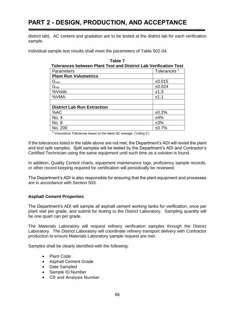
PART 2 - DESIGN, PRODUCTION, AND ACCEPTANCE
66
district lab). AC content and gradation are to be tested at the district lab for each verification sample. Individual sample test results shall meet the parameters of Table 502-04.
Table 7 Tolerances between Plant Test and District Lab Verification Test
Parameters Tolerances 1
Plant Run Volumetrics
Gmm ±0.015
Gmb ±0.024
%Voids ±1.3
%VMA ±1.1
District Lab Run Extraction
%AC ±0.2%
No. 4 ±4%
No. 8 ±3%
No. 200 ±0.7% 1
Volumetrics Tolerances based on the latest QC average, (“rolling 5”) If the tolerances listed in the table above are not met, the Department’s ADI will revisit the plant and test split samples. Split samples will be tested by the Department’s ADI and Contractor’s Certified Technician using the same equipment until such time as a solution is found. In addition, Quality Control charts, equipment maintenance logs, proficiency sample records, or other record keeping required for certification will periodically be reviewed. The Department’s ADI is also responsible for ensuring that the plant equipment and processes are in accordance with Section 503.
Asphalt Cement Properties
The Department’s ADI will sample all asphalt cement working tanks for verification, once per plant visit per grade, and submit for testing to the District Laboratory. Sampling quantity will be one quart can per grade. The Materials Laboratory will request refinery verification samples through the District Laboratory. The District Laboratory will coordinate refinery transport delivery with Contractor production to ensure Materials Laboratory sample request are met. Samples shall be clearly identified with the following:
Plant Code
Asphalt Cement Grade
Date Sampled
Sample ID Number
CD and Analysis Number
PART 2 - DESIGN, PRODUCTION, AND ACCEPTANCE
67
District Laboratories with equipment will test and report Dynamic Shear and phase angle, and one Rotational Viscosity per grade per month per refinery. If the sample meets all criteria, production continues. Should the working tank sample fail, the district laboratory will promptly notify the Project Engineer and the Contractor. The Contractor shall notify the Supplier. Additionally, the DLE must investigate to determine the cause of failure. The following is general guidance for investigating failures:
Compare working tank results to refinery results, transport results, and previous working tanks results. Does the material have a history of problems that would have resulted in similar problems?
Send samples to the Materials Laboratory for complete analysis.
Check maintenance schedules for the working tank to find out what was done. When the coils were last cleaned? When the tank was last cleaned?
Inspect facilities, checking the history of the Supplier material, etc.
Check the temperature on the working tank.
Check whether or not a different brand or grade of material has been added to the tank. Was the tank drained sufficiently before adding new material?
Test rotational viscosity. If it is determined that material in the working tank does not meet specification requirements, then plant production shall cease until corrections are made. Asphalt cement in the plant’s working tank shall meet the specifications of the asphalt cement required on the JMF.
Percent Anti-Strip
An anti-strip additive shall be added to all mixtures at no less than the minimum rate on the approved JMF. The Department’s ADI will test for the amount of anti-strip. If the check performed indicates that the amount of anti-strip added is not in accordance with the JMF, the Contractor must make adjustments so that the correct amount of anti-strip additive will be added to the mixture. If the second check indicates that the mixture is still not receiving the correct percentage of anti-strip, production for DOTD projects shall be terminated until adequate adjustments can be made to the system or the system can be recalibrated. The results of the percent anti-strip (i.e. 0.6% by weight) will be entered into the Department’s approved software. These readings are to be reported once per lot by the Contractor. The basic method of checking the percent anti-strip in the mixture is to monitor the flow of additive for a continuous time sufficient for an accurate calculation. In order to proceed with the calculations for the percent anti-strip, the Certified Technician must know the unit weight of the anti-strip additive at any given temperature. The anti-strip Supplier must make the unit weight information available or a one-gallon sample may be weighed at the plant to determine this value.
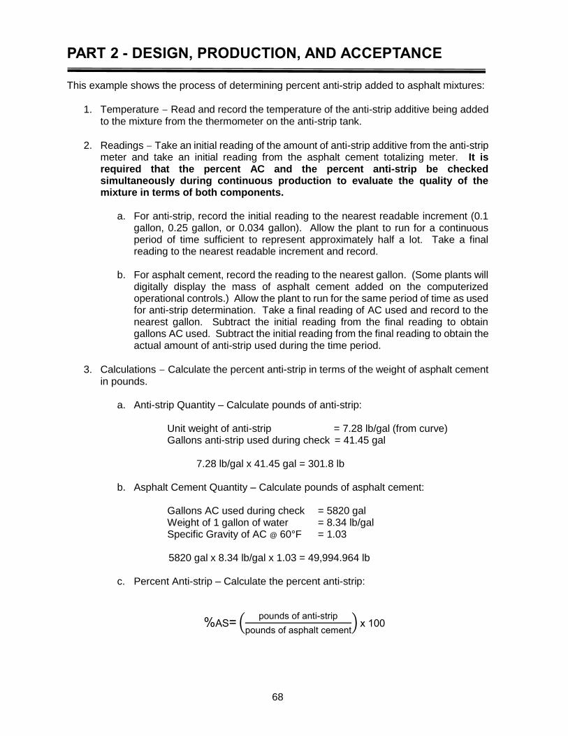
PART 2 - DESIGN, PRODUCTION, AND ACCEPTANCE
68
This example shows the process of determining percent anti-strip added to asphalt mixtures:
1. Temperature – Read and record the temperature of the anti-strip additive being added to the mixture from the thermometer on the anti-strip tank.
2. Readings – Take an initial reading of the amount of anti-strip additive from the anti-strip meter and take an initial reading from the asphalt cement totalizing meter. It is required that the percent AC and the percent anti-strip be checked simultaneously during continuous production to evaluate the quality of the mixture in terms of both components.
a. For anti-strip, record the initial reading to the nearest readable increment (0.1
gallon, 0.25 gallon, or 0.034 gallon). Allow the plant to run for a continuous period of time sufficient to represent approximately half a lot. Take a final reading to the nearest readable increment and record.
b. For asphalt cement, record the reading to the nearest gallon. (Some plants will
digitally display the mass of asphalt cement added on the computerized operational controls.) Allow the plant to run for the same period of time as used for anti-strip determination. Take a final reading of AC used and record to the nearest gallon. Subtract the initial reading from the final reading to obtain gallons AC used. Subtract the initial reading from the final reading to obtain the actual amount of anti-strip used during the time period.
3. Calculations – Calculate the percent anti-strip in terms of the weight of asphalt cement in pounds.
a. Anti-strip Quantity – Calculate pounds of anti-strip:
Unit weight of anti-strip = 7.28 lb/gal (from curve) Gallons anti-strip used during check = 41.45 gal
7.28 lb/gal x 41.45 gal = 301.8 lb
b. Asphalt Cement Quantity – Calculate pounds of asphalt cement:
Gallons AC used during check = 5820 gal Weight of 1 gallon of water = 8.34 lb/gal Specific Gravity of AC @ 60°F = 1.03
5820 gal x 8.34 lb/gal x 1.03 = 49,994.964 lb
c. Percent Anti-strip – Calculate the percent anti-strip:
%AS= (pounds of anti-strip
pounds of asphalt cement) x 100

PART 2 - DESIGN, PRODUCTION, AND ACCEPTANCE
69
100x49,994.964
301.8AS%
= 0.604
= 0.6 % anti-strip
Report the final percent anti-strip additive to the nearest 0.1%.
4. Alternate Method – An alternate method is to take a printout of anti-strip and asphalt cement quantities at a specific start and stop point in time from the control room. Divide the total anti-strip quantity for that period of time by the total asphalt cement for the same period of time. Results shall be within ±0.1 of the JMF. If not, production shall be discontinued until the proper rate can be added.
If lime or other additive types are being proportioned in the asphalt mixture at the plant (and shown on the JMF) then this rate shall also be verified, via the plants meters/scales.
PWL Calculation
Assume 5 samples taken from 5 consecutive sublots of continuous production of the same mix from a plant.
5000 TONS ¾” NMS Wearing Category B Roadway
AIR VOIDS – Spec Limits are 2.5% to 4.5%. Test results for air voids are:
2.3% 2.2% 3.0% 2.9% 3.0%
AIR VOIDS – Compute PWL for 5 air voids results.
1. First, compute the mean and the standard deviation. The formula used to determine the mean is:
n
X
= n
X+...+X+X+X = X =
i
n
1=in321
Mean
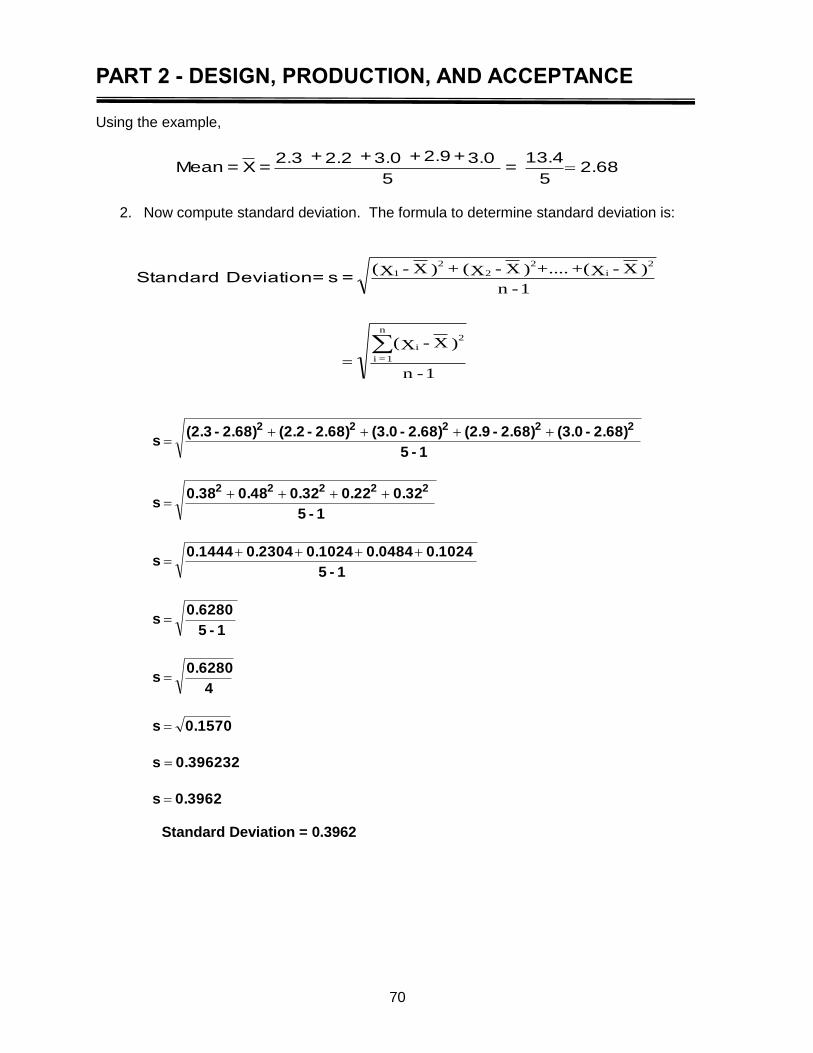
PART 2 - DESIGN, PRODUCTION, AND ACCEPTANCE
70
Using the example,
2.685
13.4 =
5
3.0+2.9+3.0+2.2+2.3 = X = Mean
2. Now compute standard deviation. The formula to determine standard deviation is:
1 - n
)X-X(
=
1 - n
)X - X(++....)X-X( + )X-X(
2
i
n
1 = i
2
i
2
2
2
1
= s = Deviation Standard
0.3962 s
0.396232 s
0.1570 s
4
0.6280 s
1 - 5
0.6280 s
1 - 5
0.1024 0.0484 0.1024 0.2304 0.1444 s
1 - 5
0.32 0.22 0.32 0.48 0.38 s
1 - 5
2.68) - (3.0 2.68) - (2.9 2.68) - (3.0 2.68) - (2.2 2.68) - (2.3 s
22222
22222
Standard Deviation = 0.3962
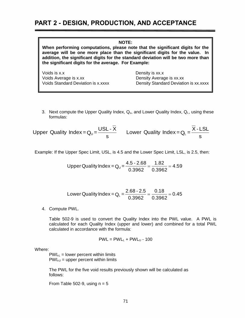
PART 2 - DESIGN, PRODUCTION, AND ACCEPTANCE
71
3. Next compute the Upper Quality Index, Qu, and Lower Quality Index, QL, using these
formulas:
Example: If the Upper Spec Limit, USL, is 4.5 and the Lower Spec Limit, LSL, is 2.5, then:
0.450.3962
0.18
0.3962
2.5 - 2.68 = Q =Index Quality Lower
4.590.3962
1.82
0.3962
2.68 - 4.5 = Q =Index Quality Upper
L
U
4. Compute PWL.
Table 502-9 is used to convert the Quality Index into the PWL value. A PWL is calculated for each Quality Index (upper and lower) and combined for a total PWL calculated in accordance with the formula:
PWL = PWLL + PWLU - 100
Where:
PWLL = lower percent within limits PWLU = upper percent within limits The PWL for the five void results previously shown will be calculated as follows:
From Table 502-9, using n = 5
s
LSL - X = Q =Index Quality Lower
s
X - USL = Q =Index Quality Upper LU
NOTE: When performing computations, please note that the significant digits for the average will be one more place than the significant digits for the value. In addition, the significant digits for the standard deviation will be two more than the significant digits for the average. For Example: Voids is x.x Density is xx.x Voids Average is x.xx Density Average is xx.xx Voids Standard Deviation is x.xxxx Density Standard Deviation is xx.xxxx
PART 2 - DESIGN, PRODUCTION, AND ACCEPTANCE
72
The PWLU which corresponds to 4.59 is 100. The PWLL which corresponds to 0.45 is 66.
Total PWL = PWLU + PWLL – 100 = 100 + 66 – 100 = 66
From 502.05, Quality Control and Plant Acceptance, the rolling five test must meet 71 PWL. If the latest rolling five test results indicate less than 71 PWL then the Contractor will take corrective action or cease production.
Roadway Quality Control
The Contractor shall perform roadway operations in accordance with Subsections 502.07, 502.08 and 502.09. Quality control shall be performed in accordance with Subsection 502.11. The Contractor shall constantly monitor equipment, materials, and processes to ensure that density and surface tolerance requirements are met. Quality control testing and inspection shall be sufficient to ensure a smooth and homogenous pavement, free from segregation, truck ends, raveling, tearing, streaking, rutting, cracking, shoving, dragging of rocks, and rippling.
Mixture temperature has a substantial effect on the density of the mat and shall be sufficiently monitored. The Contractor shall coordinate the plant production rate with transportation and placement rates to ensure continuous placement of mix. The Contractor shall monitor placement to ensure that cross-slope, grade, and transverse requirements are met as specified in Table 502-5, Subsection 502.11, and the Materials Sampling Manual.
Density
The contractor shall supply a sufficient number of rollers and experienced operators to ensure consistent density transversely as well as longitudinally along the paving strip. The contractor shall maintain consistent quality control to meet PWL requirements for mainline mixtures as well as required densities for minor mixes.
The contractor shall have a roadway quality control plan that monitors density for consistency and implements needed adjustments to meet 100% compliance with specifications.
Roadway Inspection
Inspection of Mixture on Roadway
Department personnel shall visually inspect the asphalt mixture. The Certified Inspectors are to evaluate the mixture both at the plant and at the jobsite. Mixtures exhibiting the following deficiencies shall not be placed:
Segregation
Contamination
Lumps
Non-uniform coating
Excessive temperature variations
Other deficiencies Mixture contamination, alignment deviations, variations in surface texture and appearance or other deficiencies apparent on visual inspection will not be accepted. Poor construction

PART 2 - DESIGN, PRODUCTION, AND ACCEPTANCE
73
practices such as inadequate handwork, improper joint construction, or other deficiencies apparent on visual inspection will not be accepted. Deficiencies revealed by visual inspection both after placement and before final acceptance are to be corrected at the Contractor’s expense. If a load of asphalt mix is suspected of deficiencies, but is allowed to be placed, the paving Inspector will sample the asphalt mix for testing. The paving Inspector will document the exact location where the suspect material was placed. Materials identified as being deficient may require subsequent removal and replacement at the contractor’s expense. The Department personnel are to observe haul trucks for conformity to certification. If haul trucks are not maintained to truck certification standards, they shall not be allowed on state projects. Areas of observation are:
Tight fitting tailgates
Dump beds – tight, clean, and smooth
Tarps – canvas or vinyl large enough to cover the top and extend over the sides (sand tarps not allowed)
Sufficient tie-downs to secure the tarp
Certification sticker(s) are legible
No fuel or fluid leaks
Diesel shall not be allowed in dump beds The DOTD Certified Paving Inspector at the laydown site is responsible for observing the performance of surface tolerance testing, checking lane widths and other grade and alignment checks and equipment suitability. In addition, the Certified Paving Inspector is responsible for maintaining a running total of tonnage delivered to the project from each plant lot. The Inspector must also document mix placement on the roadway. Plant Lots are the same as “roadway” lots, and are used to track mix placement. Continuous records of lot placement should be maintained in a field book. The Certified Paving Inspector will check yield on a continuing basis during the project and calculate the yield for each portion of a lot delivered to the roadway. Beyond these duties, the Certified Paving Inspector must observe the appearance of the mat behind the paver and the rollers, the uniformity and acceptability of joint construction and the performance of the paving train equipment. If material related problems occur at the jobsite, then the Certified Paving Inspector shall make immediate contact with the Department’s ADI so that adjustments can be made in the manufacturing and transport processes. Ensure that the Contractor must have adequate incidental equipment such as rakes, tampers, lutes, and shovels for the work being performed available at the project. This equipment must be clean and in satisfactory condition. Discarding Material
When dumping asphalt mix into the MTV at the start of paving operations, it may be necessary to discard approximately the first 200 to 300 lbs of material. This material shall be disposed of by the Contractor/Producer outside the limits of the right-of-way upon completion of the project. No deduction in lot tonnage totals shall be made for this material waste. However, the Paving Inspector is to continually monitor the truck dumping operation to assure minimal waste.
PART 2 - DESIGN, PRODUCTION, AND ACCEPTANCE
74
Lumps, Contamination, Coating
Any material that is not properly coated, has lumps, or is contaminated will be rejected prior to placement. Lumps may be indicative of moisture problems or a dryer/drum that needs to be cleaned out. If the Paving Inspector observes this deficiency, they are to notify the Contractor, DLE, and/or ADI. Operations shall be discontinued and the dryer/drum cleaned. A mix that is not properly coated will be sampled and a Ross Count performed (AASHTO T 195). Contaminated material will also be sampled. When sampling a material for future Department investigation, the Inspector must be certain to obtain a sample that is representative of the questionable material.
Temperature
The Paving Inspector is also responsible for verifying that the temperature of the material at the roadway is within specification tolerance. The temperature of the material in the truck shall be within 25°F of the bottom limit of the job mix formula (JMF). If the temperature is outside this tolerance or exceeds the upper JMF temperature limit, it is out of specifications and shall not be placed. The paving Inspector will record the job site temperature and tonnage rejected on the back of the haul ticket and void the ticket. The paving Inspector will immediately notify the Contractor, DLE and/or ADI and then check each subsequent truck until the material temperature is again within acceptable limits.
The material temperature will be recorded on the back of the haul ticket. The temperature of the mix going through the paver shall not be cooler than 245°F. In such cases, the temperature of the material and the tonnage discarded will be documented on the back of the haul ticket and the payment quantity adjusted.
An infrared thermal heat-sensing device (temperature gun) shall not be used for temperature acceptance. If questionable temperatures are measured using an infrared device, they shall be verified with a calibrated dial (stick) thermometer.
The beginning of a work shift the first three loads of a JMF for a project may be above the JMF limits but in no case greater than 350ºF. This allows for startup at the plant and for heating the MTV and paver at the beginning of paving operations.
Theoretical Yield
The estimated quantity of asphalt mix shown on the plans is the amount that should be used on the project based on a mixture that weighs 110 lbs per square yard per inch of thickness. If the project is constructed in accordance with the dimension and mat thickness shown on the plans, this plan quantity should be accurate. If less asphalt mix is used than called for by the plans, the mat will probably, on the average, be too thin.
If more asphalt mix is used than called for by the plans, the mat, on average, will probably be too thick. Additionally, a cost overrun will result. Failure to keep the actual quantity of asphalt mix used fairly close to plan quantity may require a change order. If extra material is needed for minor adjustments due to field conditions, it is imperative that current Departmental policy for overruns be strictly followed. The plan quantity is calculated on asphalt mix weighing 110 lb/sq yd/in. thickness. However, some aggregates, such as sandstone or slag, will cause the unit weight of the mixture to differ from the standard 110 lb/sq yd/in. value.
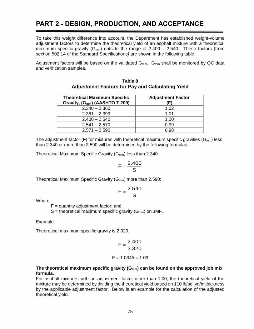
PART 2 - DESIGN, PRODUCTION, AND ACCEPTANCE
75
To take this weight difference into account, the Department has established weight-volume adjustment factors to determine the theoretical yield of an asphalt mixture with a theoretical maximum specific gravity (Gmm) outside the range of 2.400 – 2.540. These factors (from section 502.14 of the Standard Specifications) are shown in the following table.
Adjustment factors will be based on the validated Gmm. Gmm shall be monitored by QC data and verification samples.
Table 8
Adjustment Factors for Pay and Calculating Yield
Theoretical Maximum Specific Gravity, (Gmm) (AASHTO T 209)
Adjustment Factor (F)
2.340 – 2.360 1.02
2.361 – 2.399 1.01
2.400 – 2.540 1.00
2.541 – 2.570 0.99
2.571 – 2.590 0.98
The adjustment factor (F) for mixtures with theoretical maximum specific gravities (Gmm) less than 2.340 or more than 2.590 will be determined by the following formulas:
Theoretical Maximum Specific Gravity (Gmm) less than 2.340:
S
400.2F
Theoretical Maximum Specific Gravity (Gmm) more than 2.590:
S
540.2F
Where: F = quantity adjustment factor; and S = theoretical maximum specific gravity (Gmm) on JMF.
Example:
Theoretical maximum specific gravity is 2.320.
320.2
400.2F
F = 1.0345 = 1.03 The theoretical maximum specific gravity (Gmm) can be found on the approved job mix formula. For asphalt mixtures with an adjustment factor other than 1.00, the theoretical yield of the mixture may be determined by dividing the theoretical yield based on 110 lb/sq yd/in thickness by the applicable adjustment factor. Below is an example for the calculation of the adjusted theoretical yield.
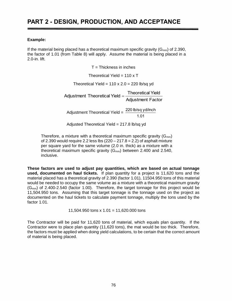
PART 2 - DESIGN, PRODUCTION, AND ACCEPTANCE
76
Example: If the material being placed has a theoretical maximum specific gravity (Gmm) of 2.390, the factor of 1.01 (from Table 8) will apply. Assume the material is being placed in a 2.0-in. lift.
T = Thickness in inches
Theoretical Yield = 110 x T
Theoretical Yield = 110 x 2.0 = 220 lb/sq yd
FactorAdjustment
YieldlTheoreticaYieldlTheoreticaAdjustment
Adjustment Theoretical Yield = 1.01
yd/inchlb/sq220
Adjusted Theoretical Yield = 217.8 lb/sq yd
Therefore, a mixture with a theoretical maximum specific gravity (Gmm) of 2.390 would require 2.2 less lbs (220 – 217.8 = 2.2) of asphalt mixture per square yard for the same volume (2.0 in. thick) as a mixture with a theoretical maximum specific gravity (Gmm) between 2.400 and 2.540, inclusive.
These factors are used to adjust pay quantities, which are based on actual tonnage used, documented on haul tickets. If plan quantity for a project is 11,620 tons and the material placed has a theoretical gravity of 2.390 (factor 1.01), 11504.950 tons of this material would be needed to occupy the same volume as a mixture with a theoretical maximum gravity (Gmm) of 2.400-2.540 (factor 1.00). Therefore, the target tonnage for this project would be 11,504.950 tons. Assuming that this target tonnage is the tonnage used on the project as documented on the haul tickets to calculate payment tonnage, multiply the tons used by the factor 1.01.
11,504.950 tons x 1.01 = 11,620.000 tons
The Contractor will be paid for 11,620 tons of material, which equals plan quantity. If the Contractor were to place plan quantity (11,620 tons), the mat would be too thick. Therefore, the factors must be applied when doing yield calculations, to be certain that the correct amount of material is being placed.
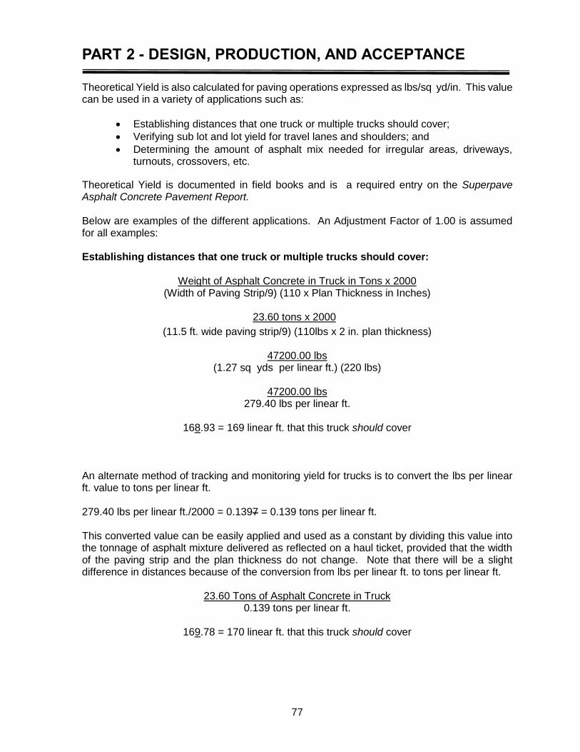
PART 2 - DESIGN, PRODUCTION, AND ACCEPTANCE
77
Theoretical Yield is also calculated for paving operations expressed as lbs/sq yd/in. This value can be used in a variety of applications such as:
Establishing distances that one truck or multiple trucks should cover;
Verifying sub lot and lot yield for travel lanes and shoulders; and
Determining the amount of asphalt mix needed for irregular areas, driveways, turnouts, crossovers, etc.
Theoretical Yield is documented in field books and is a required entry on the Superpave Asphalt Concrete Pavement Report. Below are examples of the different applications. An Adjustment Factor of 1.00 is assumed for all examples: Establishing distances that one truck or multiple trucks should cover:
Weight of Asphalt Concrete in Truck in Tons x 2000 (Width of Paving Strip/9) (110 x Plan Thickness in Inches)
23.60 tons x 2000
(11.5 ft. wide paving strip/9) (110lbs x 2 in. plan thickness)
47200.00 lbs (1.27 sq yds per linear ft.) (220 lbs)
47200.00 lbs
279.40 lbs per linear ft.
168.93 = 169 linear ft. that this truck should cover
An alternate method of tracking and monitoring yield for trucks is to convert the lbs per linear ft. value to tons per linear ft. 279.40 lbs per linear ft./2000 = 0.1397 = 0.139 tons per linear ft. This converted value can be easily applied and used as a constant by dividing this value into the tonnage of asphalt mixture delivered as reflected on a haul ticket, provided that the width of the paving strip and the plan thickness do not change. Note that there will be a slight difference in distances because of the conversion from lbs per linear ft. to tons per linear ft.
23.60 Tons of Asphalt Concrete in Truck
0.139 tons per linear ft.
169.78 = 170 linear ft. that this truck should cover
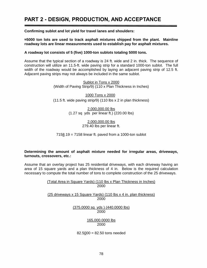
PART 2 - DESIGN, PRODUCTION, AND ACCEPTANCE
78
Confirming sublot and lot yield for travel lanes and shoulders: ≈5000 ton lots are used to track asphalt mixtures shipped from the plant. Mainline roadway lots are linear measurements used to establish pay for asphalt mixtures. A roadway lot consists of 5 (five) 1000-ton sublots totaling 5000 tons. Assume that the typical section of a roadway is 24 ft. wide and 2 in. thick. The sequence of construction will utilize an 11.5-ft. wide paving strip for a standard 1000-ton sublot. The full width of the roadway would be accomplished by laying an adjacent paving strip of 12.5 ft. Adjacent paving strips may not always be included in the same sublot.
Sublot in Tons x 2000 (Width of Paving Strip/9) (110 x Plan Thickness in Inches)
1000 Tons x 2000
(11.5 ft. wide paving strip/9) (110 lbs x 2 in plan thickness)
2,000,000.00 lbs (1.27 sq yds per linear ft.) (220.00 lbs)
2,000,000.00 lbs
279.40 lbs per linear ft.
7158.19 = 7158 linear ft. paved from a 1000-ton sublot
Determining the amount of asphalt mixture needed for irregular areas, driveways, turnouts, crossovers, etc.: Assume that an overlay project has 25 residential driveways, with each driveway having an area of 15 square yards and a plan thickness of 4 in. Below is the required calculation necessary to compute the total number of tons to complete construction of the 25 driveways.
(Total Area in Square Yards) (110 lbs x Plan Thickness in Inches) 2000
(25 driveways x 15 Square Yards) (110 lbs x 4 in. plan thickness)
2000
(375.0000 sq yds ) (440.0000 lbs) 2000
165,000.0000 lbs
2000
82.5000 = 82.50 tons needed

PART 2 - DESIGN, PRODUCTION, AND ACCEPTANCE
79
Actual Yield
Actual yield is the actual amount of asphalt mixture placed in terms of pounds per square yard. It is the responsibility of the Certified Paving Inspector to maintain a constant check on actual yield during paving operations to ensure that at the end of the project, actual yield and theoretical yield will match closely. Actual yield should be checked and compared to the theoretical yield several times during a paving day, at the end of a lot, and at the end of the project. Since mat thickness is averaged and not exact, actual yield may vary slightly from theoretical yield on an individual truck or even for several truckloads. However, it should never run consistently over or under theoretical yield. If actual yield is consistently over or under theoretical yield, something may not be correct with the paving operation. The Contractor will then be required to identify and correct the problem, or the project will not conform to the plans.
The formula for computing actual yield is as follows:
PavementofYardsSquare
2000xUsedTonsYieldActual
Utilizing the example of establishing sub lot limits in the previous section on Theoretical Yield, a comparison against the Actual Yield shall be made and documented on the Superpave Asphalt Concrete Pavement Report.
1040 tons of asphalt mix was used for the sublot 7158 ft. long, by 11.5 ft. wide and 2 in. thick.
Square Yards = (7158 ft x 11.5 ft)/9 ft/yd2 = (82317.00)/9 = 9146.33 = 9146 square yards
yardssquare9146
2000xUsed Tons1040YieldActual
yardssquare9146
lbs.00 2,080,000YieldActual
Actual Yield = 227.421 = 227.4 lbs/sq yd
Therefore, the difference between the Theoretical Yield of 220.0 lbs/sq yd/plan thickness in inches and the Actual Yield of 227.4 lbs/sq yd used is 7.4 lbs/ sq yd over. This indicates that the mat may be too thick and an overrun for this sublot has occurred.
One method for determining percent overruns or underruns can be calculated from the tonnage.1000 tons were needed for the area to be paved based on Theoretical Yield for the sub lot. 1040 tons were actually used for the area.
% Overrun = (Actual tons laid − Theoretical tons
Theoretical tons) x100
% Overrun = (40 tons over
1000 tons based on Theoretical Yield ) x100
% Overrun = (0.4000) x 100 = 4.0%
PART 2 - DESIGN, PRODUCTION, AND ACCEPTANCE
80
As stated earlier, Actual Yield should never run consistently over or under theoretical yield. Overruns or underruns for the Contract Item may require a Change Order in accordance with the DOTD Construction Contract Administration Manual.
Joint Construction
All pavement joints shall be constructed according to the requirements of the specifications. They shall be inspected by the Department’s Inspectors for satisfactory compliance to the Department standards in accordance with the procedures described in this manual and the Standard Specifications.
Longitudinal Joints
Department specifications stipulate that, during the construction of a longitudinal joint, no material will be scattered loosely over the uncompacted mat. The overlapped material shall be pushed back to form a vertical edge above the joint. The vertical edge shall then be compacted by rolling to form a smooth, sealed joint.
Coarse aggregate shall not be raked from the asphalt mixture at the joint. Excess material or spillage shall not be pushed onto the uncompacted mat. If workers cast the overlap onto the uncompacted mat, this material will be segregated and not visually appealing. Such material will ravel under traffic. If this occurs, the Inspector must require that the material be removed from the fresh mat before the roller approaches the area.
After compaction, a properly constructed longitudinal joint should not be high or low when compared to the adjacent mat. There should be no rough material at the joint location. The joint must be properly sealed. There can be no opening allowed between the mats. The joint should not overlap onto the previously compacted mat. After compaction, the Inspector must check the joint for all applicable points. The Inspector should also place a 10-ft. static straightedge across the joint, transverse to the centerline. If there is any deviation greater than the transverse surface tolerance applicable to that course listed in Table 502-5 of the Standard Specifications, corrective action will be required. Checking the joint with a 10-ft. static straightedge is effective on a tangent slope, but will not work on a two-lane roadway with center crown. For a roadway with center crown, the Inspector will place a 10-ft. static straightedge across the joint with approximately 1 ft. resting on the new mat. If the fluff was not adequate, there will be a dip at the joint and the paver shall be adjusted. Transverse Joints
A transverse joint must be formed whenever paving operations are discontinued long enough for the temperature of the asphalt mixture being placed to fall more than 50° F from the lower limit of the JMF. This includes the interruption of paving operations at the end of the day. Equipment malfunctions, plant problems, or weather conditions can also cause an interruption of the paving operations, which will require construction of a transverse joint.
The Inspector will visually inspect the joint longitudinally and transversely to determine if there are any apparent deviations in the area. The Inspector will then place a 10 ft. metal static straightedge at several locations across the joint location and attempt to push a shim the
PART 2 - DESIGN, PRODUCTION, AND ACCEPTANCE
81
thickness of the applicable specification deviation beneath the straightedge. The joint shall comply with Subsection 502.07.3.2.
If the transverse joint does not meet specification requirements, the Contractor shall correct it before the paving operation proceeds. The paving operation shall not proceed further than 100 ft. from the transvers joint until the transverse joint meets specifications. Only the minimum amount of handwork required to correct the deficiency will be allowed and only the affected area shall be worked. This handwork must also be completed so that the area can be recompacted before the mat surface has cooled beyond the point where compaction cannot be achieved. If the deviation at the joint is excessive (i.e., beyond that which can be satisfactorily repaired with a minimum amount of handwork) the contactor will be required to completely remove the material placed and reconstruct the joint with the paver. After any required corrections have been completed and the area recompacted, the Inspector must recheck the joint to ensure that the corrective action has met all Department surface finish requirements and that the surface texture of the corrected area is acceptable. If the Inspector is still unable to approve the joint, the Contractor must take additional corrective measures.
Segregation
If the material appears to be segregated in the truck, the Inspector shall determine if the degree of segregation is severe enough to warrant rejection. If the load is placed, the Inspector is to sample the material for subsequent testing. If the material appears segregated in the truck, the Inspector must check the mat carefully behind the paver. If segregation is apparent, the Inspector shall notify the Project Engineer and the ADI. Future trucks showing segregation will be rejected until the problem is corrected. If material does not appear segregated in trucks, but the mat exhibits segregation, the Inspector shall require the Contractor to identify and correct the problem immediately. If the problem cannot be corrected, operations shall be discontinued. Segregated areas of compacted asphalt mix will be subject to Department investigation for acceptability and may be removed and replaced at the Contractor’s expense. As previously stated, Section 503.14 of the Standard Specifications requires the use of a material transfer vehicle (MTV) when placing the final two lifts of asphalt mix on the roadway travel lanes. The three main objectives in requiring the MTV are to reduce segregation, improve surface smoothness, and promote continuous, non-stop paving. Asphalt mixtures may be placed without the use of the MTV when placing base course mixtures, leveling, and shoulders or as allowed by Subsection 503.14. The Certified Paving Inspector should continually monitor the finished mat for any segregated area. When paving without an MTV (dumping asphalt mix directly into the paver hopper from the haul truck), proper truck exchange is critical to the production of a smooth, uniform mat. The truck should never bump the paver and should not rest on the paver hopper. Material should not be dumped or spilled in front of the paver. The material should be dumped into the paver in a large mass to prevent segregation. Segregation on Mat
Segregated areas of the mat will have a different look than the rest of the roadway surface. These areas will be open-textured. The size of these areas will vary depending on the severity of the cause. It is not uncommon for such open-textured area to be 30 ft. long and the full width of the paver, although many of these areas are confined to 15-ft. lengths and just the center two-thirds of the paver’s width. These areas have a tendency to become more
PART 2 - DESIGN, PRODUCTION, AND ACCEPTANCE
82
noticeable after being exposed to traffic and can best be observed when the angle of reflective light is low (i.e., early morning or late evening) or just after a rainfall. Under these conditions, these open-textured areas remain wet and dark looking when compared to the drier surrounding areas. Truck Ends
Truck end segregation is caused by the coarse aggregate fractions separating from the fine aggregate fractions in either the production, transport or the laydown processes. In severe cases, this separation can be observed at the plant when noticeable roll-down of the coarse aggregate occurs toward the sides, the tailgate, and the cab area of the haul unit. Such roll-down segregation results in a truck end in one or more of the following ways.
The segregated roll-down material at the tailgate is fed onto an empty slat conveyor and fed back to the paver augers as segregated material, causing a truck end.
The segregated roll-down material on the sides of the haul truck is fed into the wings of the paver hopper. When these wings are dumped (i.e., the material in the wings is fed to the slat feeder), this segregated roll-down material will cause a truck end.
The segregated roll-down material at the cab end of the truck (which is the last to be fed from the truck) will roll down the entire length of the bed, and if fed by itself to the augers, will cause a truck end.
Numerous investigations have identified the material at truck end locations to be inferior in quality, possessing low asphalt content, with an extremely coarse gradation and a low roadway density. The net result of these poor mix qualities is an area of roadway that will crack and/or ravel if used as a wearing course or be structurally deficient and subject to moisture damage if used as a binder or base course. Beyond the poor mixture characteristics associated with these truck end segregations, a poor ride is most often the result. This poor ride is identified by dips at the same intervals previously described. These dips are due to a paver’s screed settling on the coarse mix during construction (i.e., a mixture with high air voids offers less resistance to the screed) or the dips develop later under traffic, when high-void areas that have low initial density are compacted more than the well-compacted areas immediately adjacent. Regardless of where the segregation is first observed, truck-end segregation areas on the roadway are to be eliminated or minimized to the best degree possible. It is an important point to remember that the material is segregating through whatever handling processes it is being subjected to (e.g., coated in a dryer/drum, conveyed into a surge/storage silo, emptied into a large trailer truck and dumped onto a paver’s empty slat feeder). It is an equally important point to know that some well-graded and well-coated mixes do not segregate given an identical handling process. Consequently, not all attempts to eliminate or effectively minimize truck-end segregation have been taken until one or more mixture, process, and handling changes have been tried and implemented.
PART 2 - DESIGN, PRODUCTION, AND ACCEPTANCE
83
The following steps should be taken whenever segregation is observed:
Paver wings should not be dumped until the end of the paving day. Asphalt mix dumped from paver wings shall be discarded and not incorporated into the roadway.
Haul trucks are to be loaded to minimalize segregation. When correcting segregation issues, haul trucks should be loaded with a minimum of three drops, the last of which shall be in the middle of the bed. It is the intent of this loading procedure to first load as close to the tailgate and cab areas as possible to minimize roll-down and then complete the load in the middle of the bed.
During the exchange of trucks at the paver (when no MTV is required), the level of material remaining in the paver hopper should not drop so low as to expose the hopper feed slats. Keeping the slat feeders covered with material will aid the mixing of whatever roll-down material exists with non-segregated material before it is fed to the paver augers.
The paver augers should be run at minimum revolution to reduce segregation. Further, the level of material should be maintained to at least that of the auger shaft. Augers should run at least 95% of the time.
Any segregated areas on the roadway that occur at regular intervals must be eliminated or effectively minimized. The Paving Inspector must be aware of the potential problem and maintain constant communication with the production and paving personnel when a problem exists. The Project Engineer will instruct the Contractor/Producer to correct problems associated with segregation.
Coordination of Paving Operations
Coordination of Paving Operations with Production and Transport One of the most important elements of successful asphalt paving operations is the coordination of paving speed to plant production and hauling capacity. A start and stop operation will not produce a uniform mat and smooth riding surface. A start and stop paving operation is specifically prohibited by the specifications. The Standard Specifications require the Contractor/Producer to coordinate and manage plant production, transportation, and laydown operations to ensure reasonably continuous plant and paving operations with minimum idle time between loads. Delivery of the material to the paver must be at a uniform rate. There should be no waiting time between truckloads; nor should a large number of trucks be waiting to discharge into the paver or MTV. The correct speed for the paver is such that as one truck empties and pulls away, one truck is waiting to move into discharge position immediately. If sufficient hauling vehicles are not available to maintain a smooth, coordinated paving operation, the specifications authorize the discontinuance of operations or requirement of additional trucks. Paver speed and plant production should also be tied to time required for rollers to achieve compaction in the paving train.
PART 2 - DESIGN, PRODUCTION, AND ACCEPTANCE
84
Analysis of Test Data in the Acceptance Decision
F-test and t-test Method for Comparing Two Sets of Data*
F (variances) and t (means) tests are two hypothesis tests used to compare two sets of data. In this case, it refers to Contractor and DOTD test results. The F-test provides a method for comparing the variances of two sets of data. Differences in means are assessed by the t-test. For samples from the same normal population, the statistic F, which is the ratio of the two sample variances, has a sampling distribution called the F-distribution. For process verification testing, the F-test is based on the ratio of the sample variance of the Contractor’s test results and the sample variance of DOTD test results. The t-statistic and the t-test can be used to test whether the sample mean of the Contractor’s test results and DOTD test results came from populations with the same mean. When comparing Contractor and DOTD samples, it is important that proper random sampling be utilized. Because sources of variability influence the population parameters, the two sets of test results must be sampled over the same time period, and the same sampling and testing procedures must be used. If it is determined a significant difference is likely between either the variances or the means, the source of the difference should be identified. The identification of a difference is just that, i.e., notice that a difference exists. The reason for the difference must be determined. The level of significance used for comparison in F & t of Contractor and DOTD results is 0.025. Below is an excerpt from Appendix F of FHWA-RD-02-095 (Optimal Procedures for Quality Assurance Specifications). The web link for this document is: https://www.fhwa.dot.gov/publications/research/infrastructure/pavements/pccp/02095/02095.pdf (Retrieved October 30, 2016)
Since the values used for the t-test are dependent upon whether or not the variances are assumed equal for the two data set, it is necessary to test the variances before the means. The intent is to determine whether the difference in the variability of the contractor’s tests and agency’s tests is larger than might be expected by chance if they came from the same population. It does not matter which variance is larger. After comparing the F-test results, one of the following will be concluded:
The two sets of data have different variances because the difference between the two sets of test results is greater than is likely to occur from chance if their variances are actually equal.
There is no reason to believe the variances are different because the difference is not so great as to be unlikely to have occurred from chance if the variances are actually equal.
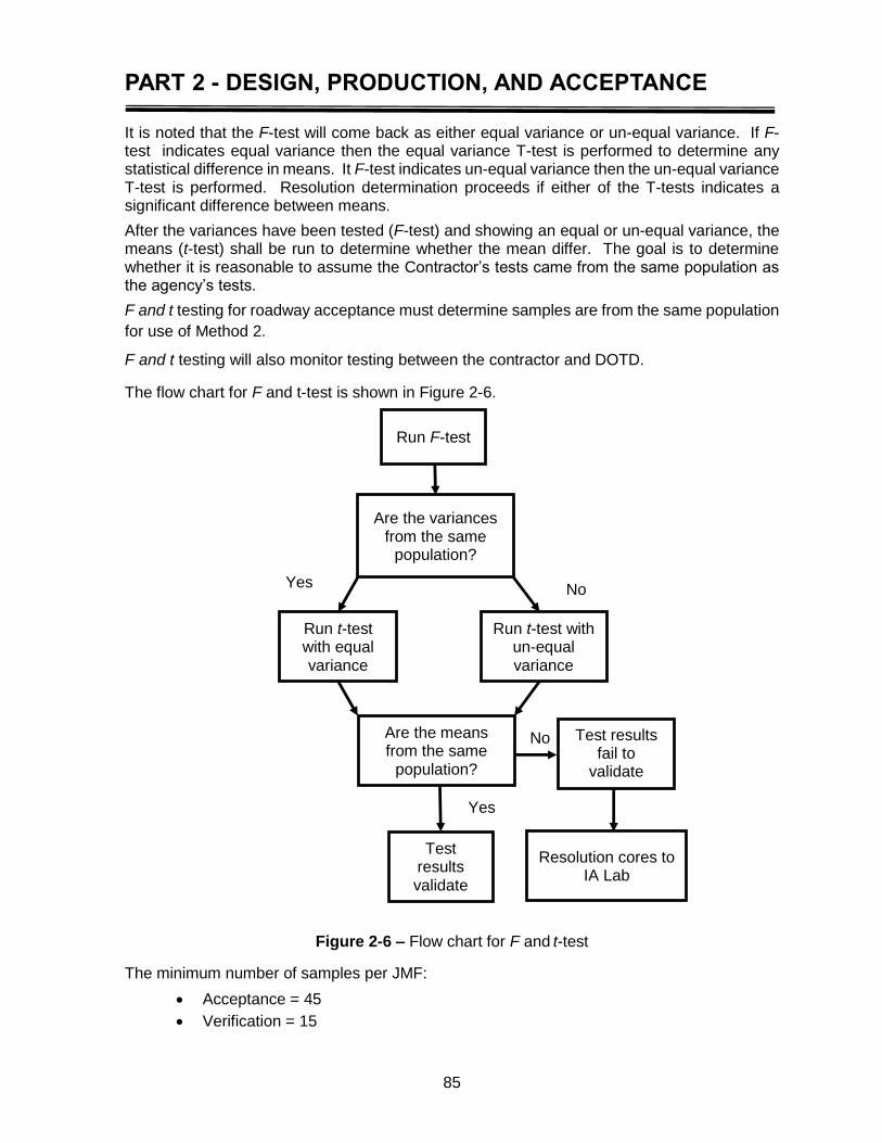
PART 2 - DESIGN, PRODUCTION, AND ACCEPTANCE
85
It is noted that the F-test will come back as either equal variance or un-equal variance. If F-test indicates equal variance then the equal variance T-test is performed to determine any statistical difference in means. It F-test indicates un-equal variance then the un-equal variance T-test is performed. Resolution determination proceeds if either of the T-tests indicates a significant difference between means.
After the variances have been tested (F-test) and showing an equal or un-equal variance, the means (t-test) shall be run to determine whether the mean differ. The goal is to determine whether it is reasonable to assume the Contractor’s tests came from the same population as the agency’s tests.
F and t testing for roadway acceptance must determine samples are from the same population
for use of Method 2.
F and t testing will also monitor testing between the contractor and DOTD.
The flow chart for F and t-test is shown in Figure 2-6.
Figure 2-6 – Flow chart for F and t-test
The minimum number of samples per JMF:
Acceptance = 45
Verification = 15
Run F-test
Are the variances from the same
population?
Run t-test with equal variance
Test results fail to
validate
Are the means from the same
population?
Test results validate
Yes No
Yes
No
Run t-test with un-equal variance
Resolution cores to IA Lab
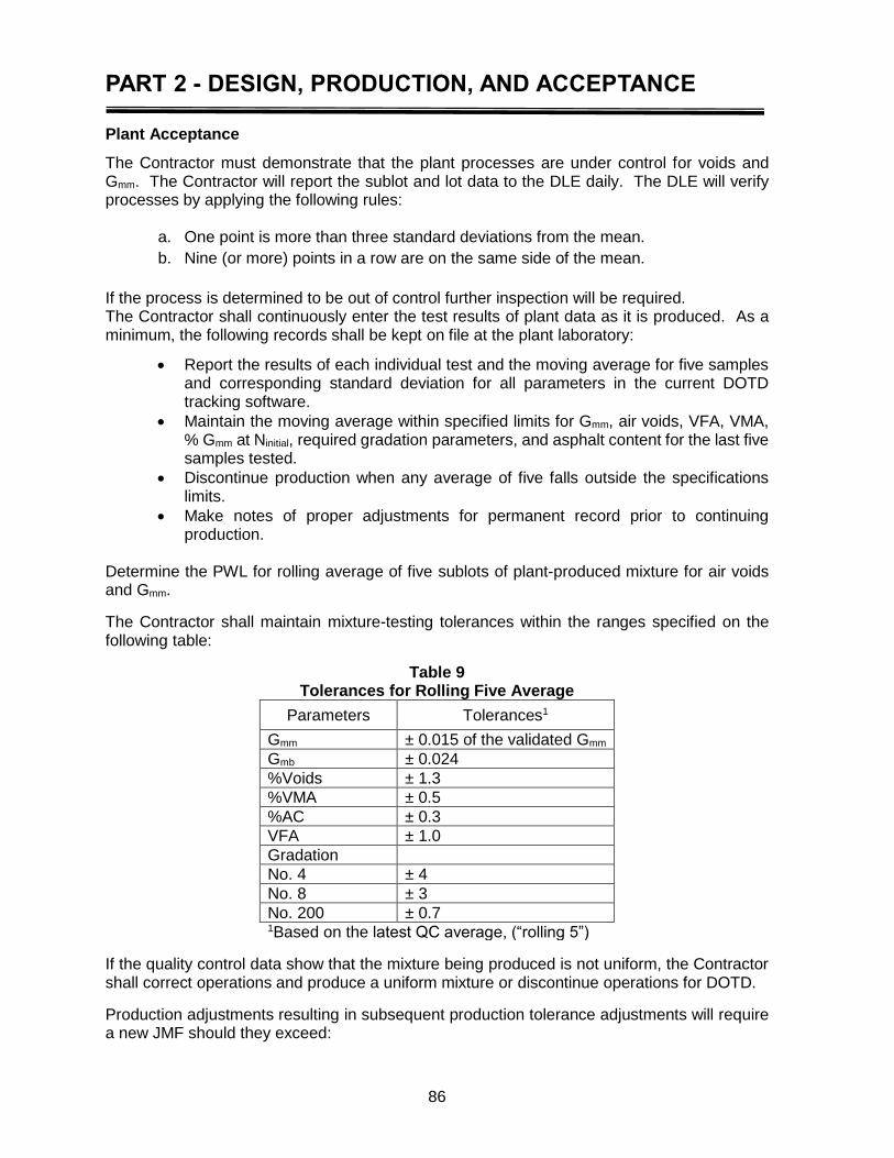
PART 2 - DESIGN, PRODUCTION, AND ACCEPTANCE
86
Plant Acceptance
The Contractor must demonstrate that the plant processes are under control for voids and Gmm. The Contractor will report the sublot and lot data to the DLE daily. The DLE will verify processes by applying the following rules:
a. One point is more than three standard deviations from the mean.
b. Nine (or more) points in a row are on the same side of the mean.
If the process is determined to be out of control further inspection will be required. The Contractor shall continuously enter the test results of plant data as it is produced. As a minimum, the following records shall be kept on file at the plant laboratory:
Report the results of each individual test and the moving average for five samples and corresponding standard deviation for all parameters in the current DOTD tracking software.
Maintain the moving average within specified limits for Gmm, air voids, VFA, VMA, % Gmm at Ninitial, required gradation parameters, and asphalt content for the last five samples tested.
Discontinue production when any average of five falls outside the specifications limits.
Make notes of proper adjustments for permanent record prior to continuing production.
Determine the PWL for rolling average of five sublots of plant-produced mixture for air voids and Gmm.
The Contractor shall maintain mixture-testing tolerances within the ranges specified on the following table:
Table 9 Tolerances for Rolling Five Average
Parameters Tolerances1
Gmm ± 0.015 of the validated Gmm
Gmb ± 0.024
%Voids ± 1.3
%VMA ± 0.5
%AC ± 0.3
VFA ± 1.0
Gradation
No. 4 ± 4
No. 8 ± 3
No. 200 ± 0.7 1Based on the latest QC average, (“rolling 5”)
If the quality control data show that the mixture being produced is not uniform, the Contractor shall correct operations and produce a uniform mixture or discontinue operations for DOTD.
Production adjustments resulting in subsequent production tolerance adjustments will require a new JMF should they exceed:
PART 2 - DESIGN, PRODUCTION, AND ACCEPTANCE
87
7% of cold feed proportions
0.3% virgin asphalt content
Greater than or less than 0.015 of the validated Gmm as noted in Table 9.
Maintain a daily record of cold feed percentages and asphalt content settings.
The Contractor shall document all corrections to control the mixture and prevent any aspect of the mixture from moving outside specified limits or from varying erratically within those limits. This documentation shall include the action taken, date and time, and be initialed by the Contractor.
Roadway Acceptance
Roadway lot pay will be based on tons received on the roadway and pay adjustments will be based on Pavement Density calculated by method shown below. Surface Tolerance pay adjustment will be calculated at the end of the job.
All cores will be cut in the presence of a DOTD Inspector.
Cores sent to the district lab shall be trimmed by the Contractor at the project site in the presence of a DOTD Inspector. Only enough material shall be removed from the core to “clean up’ the bottom of any base aggregate, tack, ridges and valleys from milling, or to separate lifts. Cores shall not be trimmed more than ¼ in. from the original core height.
Roadway cores will be clearly identified with a permanent mark or paint stick. Acceptance, verification, and resolution cores will be clearly identified. See Table 10 for core ids.
The contractor will measure the lift(s) to the nearest 1/16 in. by taking three measurements at points approximately 1/3 along the circumference of the core and averaging the three measurements. The roadway inspector will record the average core thickness on the roadway report.
The contractor will supply sufficient clean paper or paper bags and clear packing tape to wrap the cores. The paper shall not be newspaper or other paper with print, writing or graphics that interfere with signature recognition.
Cores that are to be delivered to the district lab will be wrapped with the roadway inspector placing their signature on the wrapping paper.
The core will be wrapped across the inspector signature with clear wide packing tape. The core shall be sealed with a second strip of tape 90° to the first.
The contractor shall deliver the cores to the district lab the same work shift they are cut. The contractor and roadway inspector will need to coordinate delivery with the ADI, lab staff and DLE. The contractor will not take possession of the cores until it is confirmed a district lab employee will be available to accept the cores.
The Department will document, in writing, waiving the contractors’ core handling responsibilities based on the following:
o A Department representative transports the roadway cores to the district lab. o The Department measures and trims roadway cores at the district lab.
NOTE: During production, cold feed adjustments to JMF mixture proportions may be made. When any adjustments beyond ±4% for coarse or fine aggregate are made, from the initially submitted JMF values, the DLE shall be notified.
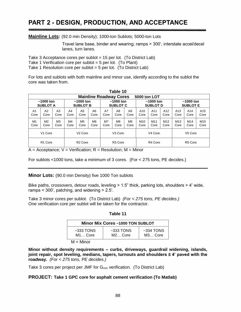
PART 2 - DESIGN, PRODUCTION, AND ACCEPTANCE
88
Mainline Lots: (92.0 min Density); 1000-ton Sublots; 5000-ton Lots
Travel lane base, binder and wearing; ramps > 300’, interstate accel/decel lanes, turn lanes.
Take 3 Acceptance cores per sublot = 15 per lot. (To District Lab) Take 1 Verification core per sublot = 5 per lot. (To Plant) Take 1 Resolution core per sublot = 5 per lot. (To District Lab)
For lots and sublots with both mainline and minor use, identify according to the sublot the core was taken from.
Table 10
Mainline Roadway Cores 5000 ton LOT
~1000 ton SUBLOT A
~1000 ton SUBLOT B
~1000 ton SUBLOT C
~1000 ton SUBLOT D
~1000 ton SUBLOT E
A1 Core
A2 Core
A3 Core
A4 Core
A5 Core
A6 Core
A7 Core
A8 Core
A9 Core
A10 Core
A11 Core
A12 Core
A13 Core
A14 Core
A15 Core
M1 Core
M2 Core
M3 Core
M4 Core
M5 Core
M6 Core
M7 Core
M8 Core
M9 Core
M10 Core
M11 Core
M12 Core
M13 Core
M14 Core
M15 Core
V1 Core
V2 Core
V3 Core
V4 Core
V5 Core
R1 Core
R2 Core
R3 Core
R4 Core
R5 Core
A = Acceptance; V = Verification; R = Resolution; M = Minor For sublots <1000 tons, take a minimum of 3 cores. (For < 275 tons, PE decides.)
Minor Lots: (90.0 min Density) five 1000 Ton sublots
Bike paths, crossovers, detour roads, leveling > 1.5” thick, parking lots, shoulders > 4’ wide, ramps < 300’, patching, and widening > 2.5’.
Take 3 minor cores per sublot. (To District Lab) (For < 275 tons, PE decides.) One verification core per sublot will be taken for the contractor.
Table 11
Minor Mix Cores ~1000 TON SUBLOT
~333 TONS M1… Core
~333 TONS M2… Core
~334 TONS M3… Core
M = Minor
Minor without density requirements – curbs, driveways, guardrail widening, islands, joint repair, spot leveling, medians, tapers, turnouts and shoulders ≤ 4’ paved with the roadway. (For < 275 tons, PE decides.)
Take 3 cores per project per JMF for Gmm verification. (To District Lab)
PROJECT: Take 1 GPC core for asphalt cement verification (To Matlab)
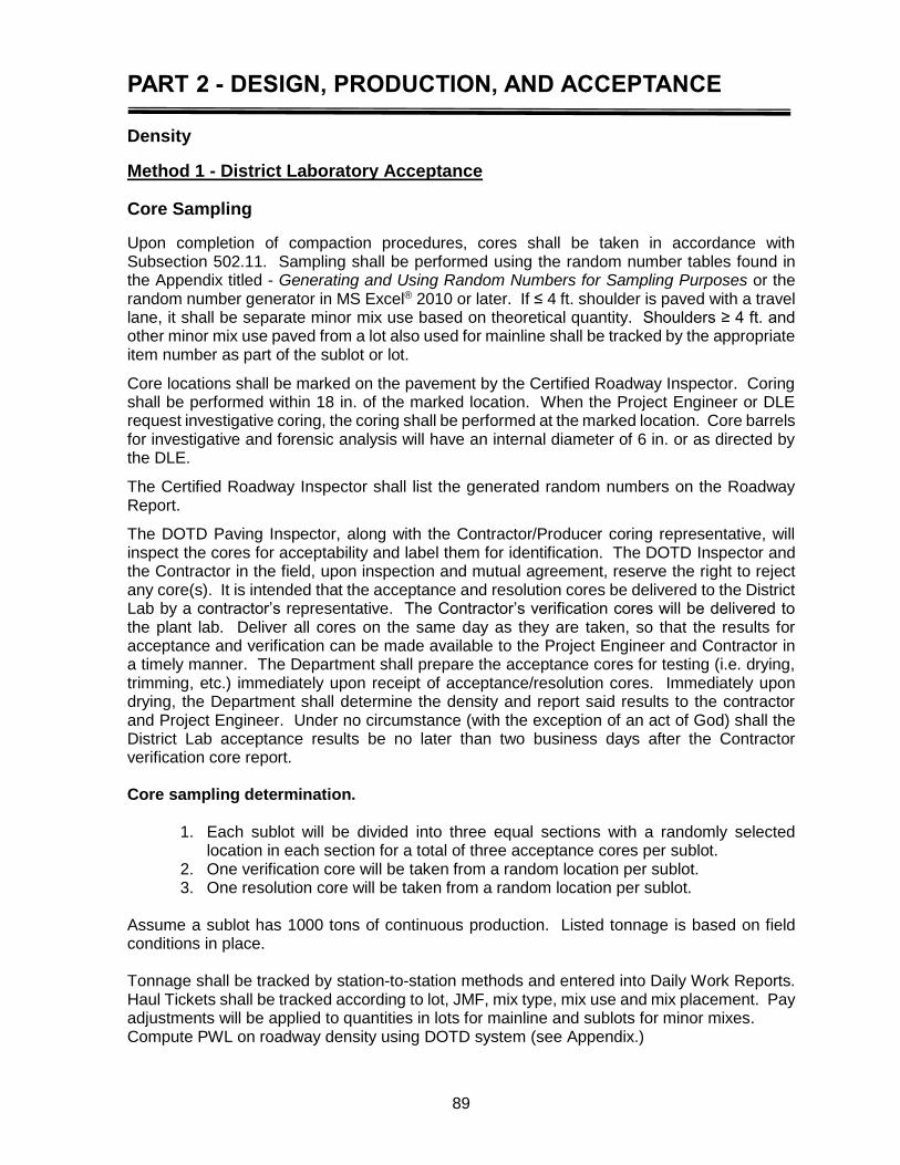
PART 2 - DESIGN, PRODUCTION, AND ACCEPTANCE
89
Density
Method 1 - District Laboratory Acceptance
Core Sampling
Upon completion of compaction procedures, cores shall be taken in accordance with Subsection 502.11. Sampling shall be performed using the random number tables found in the Appendix titled - Generating and Using Random Numbers for Sampling Purposes or the random number generator in MS Excel® 2010 or later. If ≤ 4 ft. shoulder is paved with a travel lane, it shall be separate minor mix use based on theoretical quantity. Shoulders ≥ 4 ft. and other minor mix use paved from a lot also used for mainline shall be tracked by the appropriate item number as part of the sublot or lot.
Core locations shall be marked on the pavement by the Certified Roadway Inspector. Coring shall be performed within 18 in. of the marked location. When the Project Engineer or DLE request investigative coring, the coring shall be performed at the marked location. Core barrels for investigative and forensic analysis will have an internal diameter of 6 in. or as directed by the DLE.
The Certified Roadway Inspector shall list the generated random numbers on the Roadway Report.
The DOTD Paving Inspector, along with the Contractor/Producer coring representative, will inspect the cores for acceptability and label them for identification. The DOTD Inspector and the Contractor in the field, upon inspection and mutual agreement, reserve the right to reject any core(s). It is intended that the acceptance and resolution cores be delivered to the District Lab by a contractor’s representative. The Contractor’s verification cores will be delivered to the plant lab. Deliver all cores on the same day as they are taken, so that the results for acceptance and verification can be made available to the Project Engineer and Contractor in a timely manner. The Department shall prepare the acceptance cores for testing (i.e. drying, trimming, etc.) immediately upon receipt of acceptance/resolution cores. Immediately upon drying, the Department shall determine the density and report said results to the contractor and Project Engineer. Under no circumstance (with the exception of an act of God) shall the District Lab acceptance results be no later than two business days after the Contractor verification core report. Core sampling determination.
1. Each sublot will be divided into three equal sections with a randomly selected location in each section for a total of three acceptance cores per sublot.
2. One verification core will be taken from a random location per sublot. 3. One resolution core will be taken from a random location per sublot.
Assume a sublot has 1000 tons of continuous production. Listed tonnage is based on field conditions in place. Tonnage shall be tracked by station-to-station methods and entered into Daily Work Reports. Haul Tickets shall be tracked according to lot, JMF, mix type, mix use and mix placement. Pay adjustments will be applied to quantities in lots for mainline and sublots for minor mixes. Compute PWL on roadway density using DOTD system (see Appendix.)
PART 2 - DESIGN, PRODUCTION, AND ACCEPTANCE
90
Pavement Gmb shall be determined and reported to the contractor. Percent density will be pending the results of Gmm verification.
The lot average of the plant reported Gmm must be maintained within ± 0.015 of the validated Gmm for the JMF to be within specifications.
After all cores in the lot have been measured for Gmb, randomly select one core and measure Gmm on the core after heating and breaking apart.
If Gmm is not within ± 0.024 of the averaged validation Gmm, notify the contractor. Measure an additional randomly selected core for Gmm from each sublot and average. If the average is within ±0.024 of averaged validation Gmm, take no action. The contractor has the option of being present to measure the Gmm from the additional cores.
When the averaged Gmm from randomly selected roadway cores exceeds the ±0.024 tolerance of the validated Gmm, and no pay adjustments are applied, the percent density will be calculated on the average Gmm from the randomly selected cores. The DLE will investigate the cause of the out of tolerance Gmm verification.
When pay adjustments are involved or at the request of either the contractor or DLE, the resolution cores will be sent to the IA lab for testing. Gmm measured from the resolution cored by the IA lab will be used to calculate roadway density.
In cases that do not verify, the IA Lab in conjunction with the district lab will investigate the cause of the core Gmm being out of tolerance.
If a cause cannot be determined or the core Gmm from three lots fail to verify without just cause, the JMF will be terminated.
If the sample obtained from a pavement sublot is less than 1-3/8 in. (1.375 in.) thick, the Department’s Certified Paving Inspector will reject the core and select another sampling location for that sublot by reapplication of the Random Number Tables. The DOTD Inspector will package the core for transport in accordance with Subsection 502.11.1 and send the original of the Superpave Asphalt Concrete Roadway Report with the roadway cores. Asphalt mixes placed in design layers less than 1-3/8 in. (1.375 in.) thick shall be compacted by approved methods to the satisfaction of the Project Engineer and shall not require coring.
The core sample’s official thickness measurement will be obtained by taking three measurements spaced uniformly around the circumference of the core and then averaged. The measurements will be taken and recorded to the nearest 1/16 in. on the Superpave Asphalt Concrete Roadway Report by the Roadway Technician. Should a specimen be damaged during coring operations, the core may be taken from a position longitudinally up or down the pavement within 5 ft.
All laboratories shall be equipped with a saw suitable for sawing asphalt pavement cores. This saw may be used to remove base course material (e.g., soil cement and/or curing membrane), different lifts and/or tack. Care must be taken to minimize the amount of material cut and discarded, especially from the upper surface. Cores shall be cut at the lift line to remove tack, but shall not be cut into the tested lift. With approval of the DLE, the contactor may trim
NOTE: To ensure that the cores are sufficiently free from moisture, they shall be placed in a force draft oven at 125° F until a constant mass is ensured in accordance with DOTD TR 304.

PART 2 - DESIGN, PRODUCTION, AND ACCEPTANCE
91
roadway acceptance cores in the presence of the Certified Roadway Inspector at the time of coring operations. The district lab will email the contractor the intended date and time the cores will be measured for Gmb. The contractor may have a representative observe the Gmb measurement at the district lab. The Contractor will evaluate the pavement verification cores for roadway density, which shall be computed by comparing bulk specific gravity (Gmb) of the roadway core to the corresponding sublot theoretical maximum specific gravity (Gmm). The Contractor shall report a Gmm from one verification roadway core. The percent density determined from the Contractor verification cores will be used to establish a history of consistency and for Contractor verification of Gmm. The District Lab will promptly report core densities to the contractor. The acceptance roadway cores shall be clearly identified and retained for a minimum of 10 business days after results are reported to the contractor. The contractor can request to be present for any Gmb or Gmm testing performed for pay determination. Notes on the determination of the bulk specific gravity (Gmb) of a pavement core: Weighing an object (as we do with an asphalt core) to determine its mass in air and its mass in a fluid (as we do in water) whose specific gravity is known yields sufficient data to determine its weight (mass), volume, and specific gravity. Specific gravity is defined as the ratio of the weight of a unit volume of the sample to the weight of an equal volume of water at approximately 25° ±1° C, (77 ±1.8° F). DOTD specifies that the Gmb be determined by TR 304. The equation from the test method for calculating Gmb is as follows:
Water)in WeightWeight(SSD
AirinWeightGmb
Note for Specimens with Obvious Surface Voids: As the size of the external voids in the specimen increase, it becomes difficult to determine an accurate SSD mass, because the diameter of the voids are of such size that the water will run out of them before an accurate SSD mass can be determined. If air pockets are observed on the core surface, there may be a problem with calculation of voids. To account for this, alternate test procedures may be used with approval of the DLE. One alternate test procedure is AASHTO T 275 – Bulk Specific Gravity of Compacted Bituminous Mixtures Using Paraffin, used for determining Gmb when the percent water absorbed by the specimen exceeds 2.0% as determined by the following equation:
Percent H2O Absorbed (by Volume) = Water) in WeightWeight(SSD
Air)inWeightWeight(SSD
PART 2 - DESIGN, PRODUCTION, AND ACCEPTANCE
92
In addition to DOTD TR 304 and AASHTO T 275, there exist two other methods to determine Gmb of a cored pavement specimen. One method, the Pure Volume method, is performed by measuring the thickness and diameter of the cylindrical specimen in numerous locations to calculate average values and then using the following formula to determine its volume:
Heightx2
DiameterxVolume
2
This volume is used in the denominator with dry weight in air in the numerator to determine the Gmb. The second method, which uses proprietary equipment, involves weighing the submerged specimen in a vacuumed plastic bag to determine a true volume per AASHTO T 331-07. In summary, if the Contractor or the DOTD Inspector suspects that Gmb values determined via TR 304 are yielding erroneous values, the DLE is to be notified and may approve use of these alternate methods.
Method 2 - Contractor Acceptance when approved by the DLE and Materials Engineer The Contractor shall notarize and sign DOTD 03-22-3094/15 entitled “Superpave Asphalt Concrete Roadway Report” which is used for acceptance. By notarizing and signing, the contractor is attesting that the information and test results provided on the said report are true, accurate, and correct. Contractor acceptance will be the same except as follows:
Verification and Resolution Cores
DOTD will take possession of the verification and resolution cores. The District Laboratory will perform density testing on the verification cores and perform F and t testing analysis with the Contractor acceptance data. After density testing, the District Laboratory will randomly choose one of the verification cores to perform Gmm testing. If the Gmm from this core is not within ± 0.024 of the validation Gmm for the JMF, follow procedures in Method 1 for averaging the Gmm of two more cores and then resolution measures if the average of three core Gmms do not meet the ±0.024 tolerance.
Acceptance Cores
The Contractor will take possession of acceptance cores and perform density testing at the plant laboratory where the mix was produced in accordance to DOTD TR 304. The Contractor will promptly report test data so F and t analysis can be performed. The Contractor will not use destructive test methods to determine roadway density. The acceptance roadway cores shall be clearly identified and retained for a minimum of 10 business days after testing is reported to the DLE. The roadway cores will be subject to verification by the DLE.
PART 2 - DESIGN, PRODUCTION, AND ACCEPTANCE
93
Measurement and Payment
Measurement Refer to 502.14 of the Standard Specifications
Payment Refer to 502.15 of the Standard Specifications If the Engineer adjusts the application rate of tack coat from that specified by the contract document or Standard Specifications, payment for asphalt mixture will be increased or decreased based on the difference in applied quantity of asphalt emulsion shown on paid invoices (total charges). The contractor shall provide copies of paid invoices for this determination.
Density
Mainline Payment Once test results have been determined, use Quality Level Analysis in accordance with Tables 502-9 and 502-10 of the specifications to determine percent within limits (PWL), see Appendix and Subsection 502.15 to determine pay. For an example on calculating PWL, refer to page 67. NOTE – for roadway densities there is only QL, QU does not apply to roadway density.
Payment for Mainline Small Quantities Mainline mixtures: Ensure a minimum of three cores per sublot for pay calculations. For project lots less than 1000 tons, a minimum of three cores for density will be taken. Cores for projects with less than 275 tons per JMF may be waived by the Project Engineer. Pay on density PWL.
Payment for Minor Mix Quantities Three cores per 1000 tons or minimum of 3 cores. This applies to minor mix with density. Minor mix without density will use 3 random cores per project per JMF to verify Gmm.
Surface Tolerance See Table 502-8 Standard Specifications, Section 502.12 of the Standard Specifications and this manual.

94
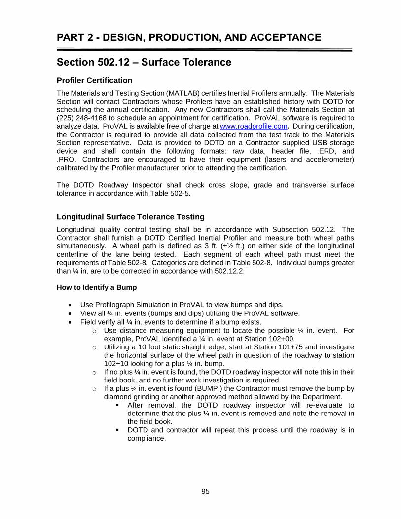
PART 2 - DESIGN, PRODUCTION, AND ACCEPTANCE
95
Section 502.12 – Surface Tolerance
Profiler Certification
The Materials and Testing Section (MATLAB) certifies Inertial Profilers annually. The Materials Section will contact Contractors whose Profilers have an established history with DOTD for scheduling the annual certification. Any new Contractors shall call the Materials Section at (225) 248-4168 to schedule an appointment for certification. ProVAL software is required to analyze data. ProVAL is available free of charge at www.roadprofile.com. During certification, the Contractor is required to provide all data collected from the test track to the Materials Section representative. Data is provided to DOTD on a Contractor supplied USB storage device and shall contain the following formats: raw data, header file, .ERD, and .PRO. Contractors are encouraged to have their equipment (lasers and accelerometer) calibrated by the Profiler manufacturer prior to attending the certification.
The DOTD Roadway Inspector shall check cross slope, grade and transverse surface tolerance in accordance with Table 502-5.
Longitudinal Surface Tolerance Testing
Longitudinal quality control testing shall be in accordance with Subsection 502.12. The Contractor shall furnish a DOTD Certified Inertial Profiler and measure both wheel paths simultaneously. A wheel path is defined as 3 ft. (±½ ft.) on either side of the longitudinal centerline of the lane being tested. Each segment of each wheel path must meet the requirements of Table 502-8. Categories are defined in Table 502-8. Individual bumps greater than ¼ in. are to be corrected in accordance with 502.12.2. How to Identify a Bump
Use Profilograph Simulation in ProVAL to view bumps and dips.
View all ¼ in. events (bumps and dips) utilizing the ProVAL software.
Field verify all ¼ in. events to determine if a bump exists. o Use distance measuring equipment to locate the possible ¼ in. event. For
example, ProVAL identified a ¼ in. event at Station 102+00. o Utilizing a 10 foot static straight edge, start at Station 101+75 and investigate
the horizontal surface of the wheel path in question of the roadway to station 102+10 looking for a plus ¼ in. bump.
o If no plus ¼ in. event is found, the DOTD roadway inspector will note this in their field book, and no further work investigation is required.
o If a plus ¼ in. event is found (BUMP,) the Contractor must remove the bump by diamond grinding or another approved method allowed by the Department.
After removal, the DOTD roadway inspector will re-evaluate to determine that the plus ¼ in. event is removed and note the removal in the field book.
DOTD and contractor will repeat this process until the roadway is in compliance.
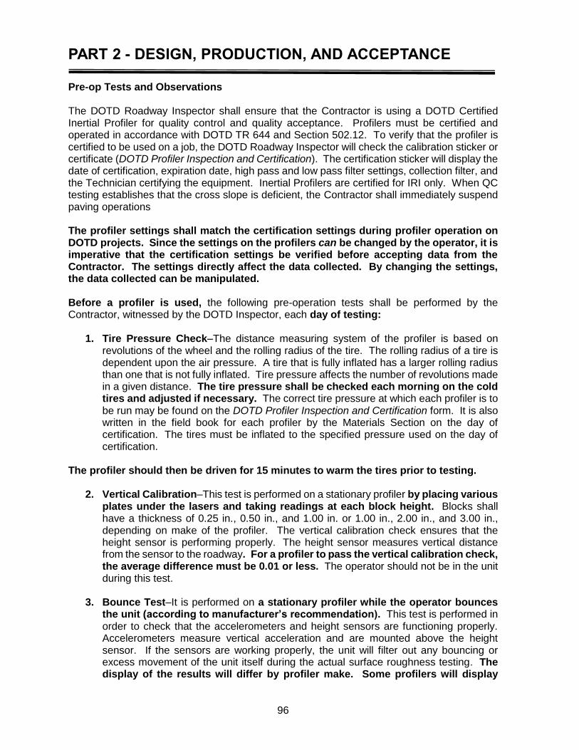
PART 2 - DESIGN, PRODUCTION, AND ACCEPTANCE
96
Pre-op Tests and Observations The DOTD Roadway Inspector shall ensure that the Contractor is using a DOTD Certified Inertial Profiler for quality control and quality acceptance. Profilers must be certified and operated in accordance with DOTD TR 644 and Section 502.12. To verify that the profiler is certified to be used on a job, the DOTD Roadway Inspector will check the calibration sticker or certificate (DOTD Profiler Inspection and Certification). The certification sticker will display the date of certification, expiration date, high pass and low pass filter settings, collection filter, and the Technician certifying the equipment. Inertial Profilers are certified for IRI only. When QC testing establishes that the cross slope is deficient, the Contractor shall immediately suspend paving operations The profiler settings shall match the certification settings during profiler operation on DOTD projects. Since the settings on the profilers can be changed by the operator, it is imperative that the certification settings be verified before accepting data from the Contractor. The settings directly affect the data collected. By changing the settings, the data collected can be manipulated. Before a profiler is used, the following pre-operation tests shall be performed by the Contractor, witnessed by the DOTD Inspector, each day of testing:
1. Tire Pressure Check–The distance measuring system of the profiler is based on revolutions of the wheel and the rolling radius of the tire. The rolling radius of a tire is dependent upon the air pressure. A tire that is fully inflated has a larger rolling radius than one that is not fully inflated. Tire pressure affects the number of revolutions made in a given distance. The tire pressure shall be checked each morning on the cold tires and adjusted if necessary. The correct tire pressure at which each profiler is to be run may be found on the DOTD Profiler Inspection and Certification form. It is also written in the field book for each profiler by the Materials Section on the day of certification. The tires must be inflated to the specified pressure used on the day of certification.
The profiler should then be driven for 15 minutes to warm the tires prior to testing.
2. Vertical Calibration–This test is performed on a stationary profiler by placing various plates under the lasers and taking readings at each block height. Blocks shall have a thickness of 0.25 in., 0.50 in., and 1.00 in. or 1.00 in., 2.00 in., and 3.00 in., depending on make of the profiler. The vertical calibration check ensures that the height sensor is performing properly. The height sensor measures vertical distance from the sensor to the roadway. For a profiler to pass the vertical calibration check, the average difference must be 0.01 or less. The operator should not be in the unit during this test.
3. Bounce Test–It is performed on a stationary profiler while the operator bounces
the unit (according to manufacturer’s recommendation). This test is performed in order to check that the accelerometers and height sensors are functioning properly. Accelerometers measure vertical acceleration and are mounted above the height sensor. If the sensors are working properly, the unit will filter out any bouncing or excess movement of the unit itself during the actual surface roughness testing. The display of the results will differ by profiler make. Some profilers will display
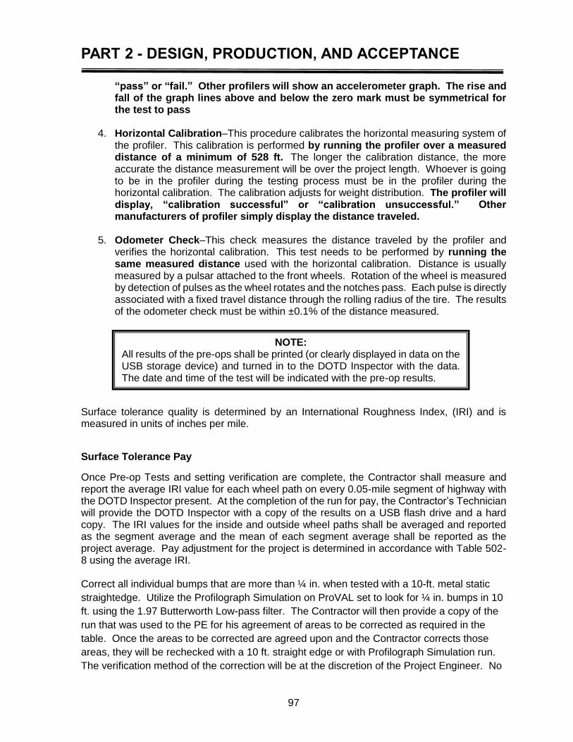
PART 2 - DESIGN, PRODUCTION, AND ACCEPTANCE
97
“pass” or “fail.” Other profilers will show an accelerometer graph. The rise and fall of the graph lines above and below the zero mark must be symmetrical for the test to pass
4. Horizontal Calibration–This procedure calibrates the horizontal measuring system of
the profiler. This calibration is performed by running the profiler over a measured distance of a minimum of 528 ft. The longer the calibration distance, the more accurate the distance measurement will be over the project length. Whoever is going to be in the profiler during the testing process must be in the profiler during the horizontal calibration. The calibration adjusts for weight distribution. The profiler will display, “calibration successful” or “calibration unsuccessful.” Other manufacturers of profiler simply display the distance traveled.
5. Odometer Check–This check measures the distance traveled by the profiler and
verifies the horizontal calibration. This test needs to be performed by running the same measured distance used with the horizontal calibration. Distance is usually measured by a pulsar attached to the front wheels. Rotation of the wheel is measured by detection of pulses as the wheel rotates and the notches pass. Each pulse is directly associated with a fixed travel distance through the rolling radius of the tire. The results of the odometer check must be within ±0.1% of the distance measured.
Surface tolerance quality is determined by an International Roughness Index, (IRI) and is measured in units of inches per mile.
Surface Tolerance Pay
Once Pre-op Tests and setting verification are complete, the Contractor shall measure and report the average IRI value for each wheel path on every 0.05-mile segment of highway with the DOTD Inspector present. At the completion of the run for pay, the Contractor’s Technician will provide the DOTD Inspector with a copy of the results on a USB flash drive and a hard copy. The IRI values for the inside and outside wheel paths shall be averaged and reported as the segment average and the mean of each segment average shall be reported as the project average. Pay adjustment for the project is determined in accordance with Table 502-8 using the average IRI. Correct all individual bumps that are more than ¼ in. when tested with a 10-ft. metal static
straightedge. Utilize the Profilograph Simulation on ProVAL set to look for ¼ in. bumps in 10
ft. using the 1.97 Butterworth Low-pass filter. The Contractor will then provide a copy of the
run that was used to the PE for his agreement of areas to be corrected as required in the
table. Once the areas to be corrected are agreed upon and the Contractor corrects those
areas, they will be rechecked with a 10 ft. straight edge or with Profilograph Simulation run.
The verification method of the correction will be at the discretion of the Project Engineer. No
NOTE: All results of the pre-ops shall be printed (or clearly displayed in data on the USB storage device) and turned in to the DOTD Inspector with the data. The date and time of the test will be indicated with the pre-op results.

PART 2 - DESIGN, PRODUCTION, AND ACCEPTANCE
98
additional areas will be required to be corrected after the agreed areas have been corrected.
The Contractor then will make their final run for pay.
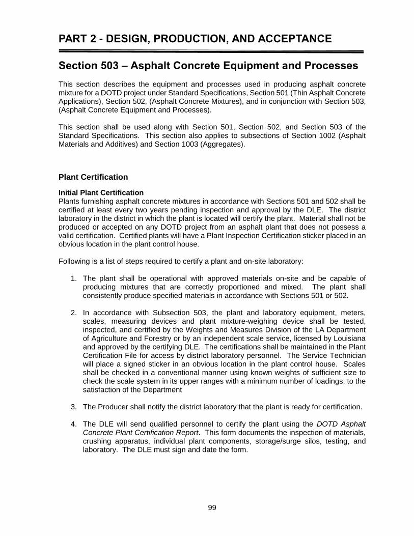
PART 2 - DESIGN, PRODUCTION, AND ACCEPTANCE
99
Section 503 – Asphalt Concrete Equipment and Processes
This section describes the equipment and processes used in producing asphalt concrete mixture for a DOTD project under Standard Specifications, Section 501 (Thin Asphalt Concrete Applications), Section 502, (Asphalt Concrete Mixtures), and in conjunction with Section 503, (Asphalt Concrete Equipment and Processes). This section shall be used along with Section 501, Section 502, and Section 503 of the Standard Specifications. This section also applies to subsections of Section 1002 (Asphalt Materials and Additives) and Section 1003 (Aggregates).
Plant Certification
Initial Plant Certification Plants furnishing asphalt concrete mixtures in accordance with Sections 501 and 502 shall be certified at least every two years pending inspection and approval by the DLE. The district laboratory in the district in which the plant is located will certify the plant. Material shall not be produced or accepted on any DOTD project from an asphalt plant that does not possess a valid certification. Certified plants will have a Plant Inspection Certification sticker placed in an obvious location in the plant control house. Following is a list of steps required to certify a plant and on-site laboratory:
1. The plant shall be operational with approved materials on-site and be capable of producing mixtures that are correctly proportioned and mixed. The plant shall consistently produce specified materials in accordance with Sections 501 or 502.
2. In accordance with Subsection 503, the plant and laboratory equipment, meters,
scales, measuring devices and plant mixture-weighing device shall be tested, inspected, and certified by the Weights and Measures Division of the LA Department of Agriculture and Forestry or by an independent scale service, licensed by Louisiana and approved by the certifying DLE. The certifications shall be maintained in the Plant Certification File for access by district laboratory personnel. The Service Technician will place a signed sticker in an obvious location in the plant control house. Scales shall be checked in a conventional manner using known weights of sufficient size to check the scale system in its upper ranges with a minimum number of loadings, to the satisfaction of the Department
3. The Producer shall notify the district laboratory that the plant is ready for certification.
4. The DLE will send qualified personnel to certify the plant using the DOTD Asphalt
Concrete Plant Certification Report. This form documents the inspection of materials, crushing apparatus, individual plant components, storage/surge silos, testing, and laboratory. The DLE must sign and date the form.

PART 2 - DESIGN, PRODUCTION, AND ACCEPTANCE
100
5. Upon satisfactory completion of the Asphalt Concrete Plant Certification Report, plant certification will be granted for a two-year period, provided the plant is maintained in accordance with the conditions under which certification was issued.
Random Conformance Inspections The plant will be inspected randomly, a minimum of once per quarter, for conformance to certification requirements by the ADI for the DLE. Upon completion of the conformance inspection, the ADI will report findings to the DLE and Contractor. If deficiencies are identified, the Contractor will need to correct these deficiencies within the agreed upon timeframe with the DLE. Failure to correct these deficiencies may result in a suspension to continue to provide mix to Department projects as determined by DLE. During these inspections, the ADI will be in charge of reviewing the following:
Inspect Plant Operations within Certification
Plant Equipment Inspection
Lab Equipment
Lab Technician’s Certifications
Observe Technician’s Test Procedures
Materials
Re-Certification Deadline
Testing Frequency Compliance All these items will be documented in the report.
Re-Certification Before the two-year certification period expires, the Producer shall notify the district laboratory that the plant is ready for re-certification. The Producer shall also notify the DLE of any major change in the manufacturing process at the plant because a new certification inspection will be required. This would include the installation of a new dryer/drum, RAP system, baghouse, storage/surge system, proportioning system, crumb rubber system, chemical additive system (warm mix), or latex system.
NOTE: When a calibration Service Technician located outside of Louisiana must be used to calibrate a scale or metering device, the Service Technician shall be licensed by the state where the Service Technician is located under standards similar to those required by Louisiana and approved by the DOTD Materials Engineer Administrator.

PART 2 - DESIGN, PRODUCTION, AND ACCEPTANCE
101
Revoked Certification If a plant fails to conform to the DOTD standards under which the certification was issued, the DLE will revoke the plant certification. The certifying DLE may also revoke plant certification when the mixture demonstrates continued non-conformance to specifications due to plant operations. Once certification has been revoked, the plant will be prohibited from supplying mix for any Department project until all deficiencies have been corrected and certification is reinstated by the DLE.
Plant Laboratory Equipment and Documentation The plant shall be equipped with a quality control/acceptance laboratory. The plant laboratory shall contain equipment to meet the requirements of the specifications and as referenced in applicable test procedures.
Design Laboratory Equipment Requirements At the time of this printing, the following equipment is required, but not limited to:
Constant Temperature Oven [100°F (38°C) to 400°F (204°C)] A 350°F (177°C) capability oven is for heating loose mix. It should be of adequate size to hold 3 gyratory molds. An oven of 125°F (52°C) capability is required for moisture content determination and for drying cores
Fume hood(s)
Specimen Ejector
Shakers, splitters, scales
Approved SHRP Gyratory Compactor, and extra molds (4 recommended)
Maximum Specific Gravity (Gmm) apparatus, including vibrating table, pycnometer, vacuum pump and drier apparatus, and residual pressure manometer
Bulk Specific Gravity (Gmb) apparatus, including balance, temperature controlled water bath equipped with overflow spigot
Equipment to perform Gsb
Saw, suitable for cutting pavement cores and gyratory specimens (wet saw preferred)
Automated Ignition Furnace
Freezer for TR 322, Tensile Strength Ratio
Breaking heads for Lottman test
Water baths, at 77°F (25°C) and at 140°F (60°C)
Draindown test apparatus
Computer and adequate connection for internet connectivity (for data tracking software and online reference manuals)
Laboratory Equipment Manual which documents equipment calibrations
Void content apparatus (FAA) and a Flat & Elongated (F&E) Gauge are required
Approved Loaded Wheel Tracker (LWT) System
Semi Circular Bend (SCB)
Other laboratory equipment used to perform Quality Control/Acceptance Testing
PART 2 - DESIGN, PRODUCTION, AND ACCEPTANCE
102
Additional equipment that may be required based on mix design submitted. The following is a list of equipment, but not limited to:
DSR
The Contractor shall supply all of this equipment. In addition, the Contractor shall provide sufficient 6-in. diameter molds and auxiliary equipment necessary for the gyratory compactor and its calibration. A loading scoop (chute) for transferring material to gyratory molds is recommended to minimize segregation and temperature loss and help in attaining consistency.
All equipment supplied by the Contractor/Producer (including electronic scales) shall be maintained, serviced and calibrated in accordance with the manufacturers’ recommendations and Subsection 503.02.2.
The DLE or their representative will inspect and approve all laboratory equipment supplied by the Contractor/Producer at the time of initial plant certification and during all subsequent inspections.
All laboratory equipment shall be calibrated and verified by the procedures in AASHTO R 18, the appropriate test methods, and by the frequency directed in R 18.
The Contractor shall maintain a Laboratory Equipment Manual containing all records for calibration of plant equipment. See the Preface and website for information and worksheets.
Production Plant Laboratory Equipment Requirements At the time of this printing, the following equipment is required, but not limited to:
Constant Temperature Oven [100°F (38°C) to 400°F (204°C)] A 350°F (177°C) capability oven is for heating loose mix. It should be of adequate size to hold three gyratory molds. An oven of 125°F (52°C) capability is required for moisture content determination and for drying cores
Fume hood(s)
Specimen Ejector
Shakers, splitters, scales
Approved SHRP Gyratory Compactor, and extra molds (four recommended).
Maximum Specific Gravity (Gmm) apparatus, including vibrating table, pycnometer, vacuum pump and drier apparatus, and residual pressure manometer
Bulk Specific Gravity (Gmb) apparatus, including balance, temperature controlled water bath equipped with overflow spigot
Saw, suitable for cutting pavement cores (wet saw preferred)
Automated Ignition Furnace
Water baths, at 77°F (25°C) and at 140°F (60°C).
Draindown test apparatus
Computer and adequate connection for internet connectivity (for data tracking software and online reference manuals)
Laboratory Equipment Manual that documents equipment calibrations
Other laboratory equipment used to perform Quality Control/Acceptance Testing
PART 2 - DESIGN, PRODUCTION, AND ACCEPTANCE
103
Scales and Meters Certification
In accordance with Subsection 503.02.2, every 90 days (or more frequently, if directed by the DLE), the plant shall have its meters, scales, and measuring devices tested, inspected, and recertified by the Weights and Measures Division of the LA Department of Agriculture and Forestry or by an independent scale service approved by the certifying DLE. The required DOTD Certification Report for Scales and Meters shall be completed and sent to the DLE each 90 days. One copy shall be retained at the plant in the Certification File. There must be a calibration sticker on each scale and meter. If the DOTD ADI has reason to question the calibration of any scale or meter, the Inspector will contact the DLE. The DLE has the authority to require the recalibration of scales or meters even though the ninety-day calibration sticker has not expired. Meters must properly display flow rate and total amount of material and liquid dispensed.
Roadway Equipment Approval
Primary roadway equipment shall be approved on a project by project basis. This equipment includes asphalt distributors, pavers, rollers, hauling, and MTV equipment. A DOTD representative will inspect and complete the Asphalt Concrete Paving Equipment Paving Approval Form. This approval signifies that the equipment is in satisfactory condition and is capable of performing its function as related to proper paving practices and in accordance with Department standards. Final approval will be granted following an evaluation of the equipment’s performance on the project. For haul trucks, separate tractor/trailer- trucks require certification together as a unit so that an accurate total tare weight may be determined. The DOTD number on separate tractor/trailers must match, showing that they were originally certified together. A new trailer shall require a new certification. Prior to certification, a truck or tractor/trailer shall have its tare weight determined on a truck scale certified by the Weights and Measures Division of the Louisiana Department of Agriculture and Forestry. This tare weight shall be determined with the fuel tank at least three quarters full. The tare weight is used to calculate the maximum payload the truck or tractor/trailer is permitted to legally haul according to its axle size. DOTD Engineering Directives and Standards (EDSM) Number III.1.1.12 outlines the Enforcement of Legal Load Requirements on Construction and Maintenance Construction Projects (See LA DOTD website.). A sample copy of the DOTD truck (and trailer, if applicable) Weight Certification Tag is shown in the Appendix.
Transport and roadway paving equipment shall perform to the satisfaction of the Project Engineer. If equipment fails to perform satisfactorily or is not maintained in acceptable condition the Inspector is to notify the Project Engineer. If an equipment malfunction is detrimental to the project, the roadway Inspector has the authority to require the removal of the equipment.
NOTE: The Contractor will not be allowed to certify more than 3 tractor and trailer combinations
PART 2 - DESIGN, PRODUCTION, AND ACCEPTANCE
104
Inspection of Plant and Roadway Equipment
The ADI and the Certified Paving Inspector are the official representatives of the Department through the authority of the DLE and Project Engineer, respectively. The concept of applying a payment adjustment to certain acceptance tests does not imply that the role of the DOTD Inspector is limited to performing or monitoring these tests. Increased dependence on Contractor/Producer quality control programs has extended the need for DOTD inspectors to be knowledgeable and vigilant concerning the design, production, transport, placement and compaction of hot-mix asphalt materials. It is intended that all requirements of the specifications shall be adhered to, not merely those to which payment adjustments are applied. If problems arise in the production, transport or paving operations, it is the Inspector’s responsibility to notify the Contractor/Producer’s representatives that the product is not meeting Department standards. The DOTD Inspector will tell the Contractor/Producer what is wrong, however, the inspector will not under no circumstances order a solution to the problem by word or action. Correcting the problem so that the product meets all requirements of the specifications is the responsibility of the Contractor/Producer. If corrective actions are not made, the Inspector is to notify the Project Engineer and DLE and make a subsequent investigation to ensure that corrective action has been taken. The Inspector will document all actions, discussions with other Department personnel and Contractor/Producer personnel, any other information relevant to the situation and will take measurements or samples, as necessary, to identify the problem. When deficiencies occur in any area of the production, transport or paving processes, the Contractor/Producer must take immediate action to correct the problem. Failure to do so can result in the discontinuance of operations for DOTD projects. Quality control shall be accomplished by a program independent of, but correlated with, the Department’s acceptance testing and shall verify that all requirements of the JMF are being achieved, and that necessary adjustments provide specification compliance. It is the intent of the specifications that mixtures provided meet 100% for all production. Whenever the mixture produced falls into areas under which payment adjustment schedules must be applied, the Contractor/Producer shall make immediate adjustments or the DOTD Inspector will require the discontinuance of operations for DOTD projects.
Plant Inspection The Department’s ADI must continually observe the entire manufacturing process when at the plant. The Inspector is to make a minimum of once per quarter inspection of the plant to ensure that it is in conformance with the standards under which certification was granted. The Inspector must be familiar with Section 503 of the Standard Specifications, Asphalt Concrete Equipment and Processes, and the certification standards for plants. It is also the Inspector’s responsibility to observe the Contractor/Producer’s testing, monitor the results, and perform any sampling and testing operations assigned to Department personnel. The plant equipment and operations are to be inspected continually during production to ensure that no malfunctions have occurred that will have a detrimental effect on the mixture.
PART 2 - DESIGN, PRODUCTION, AND ACCEPTANCE
105
The following headings indicate areas of the plant in which routine inspection is considered essential. These lists are not intended to be comprehensive or to exclude other areas from regular inspection. They are merely intended to serve as a guide to the Inspector in the performance of this responsibility.
Plant Equipment Stockpiles and Handling–Any new materials delivered to the plant are to be inspected, sampled, and tested in a timely manner so that production is not disrupted. Aggregates must be handled in a manner that will not be detrimental to the final mixture. Stockpiles shall be built without causing segregation. Segregation can be minimized if stockpiles are constructed in successive layers, not in a conical shape. Stockpiles shall be located on a clean, stable, well-drained surface to ensure uniform moisture content throughout the stockpile. The area in which the stockpiles are located shall be large enough for the stockpiles to be separated, so that no intermixing of materials will occur. Stockpiles shall not become contaminated with deleterious materials such as clay balls, leaves, sticks or non-specification aggregates. Material Proportioning–All materials used, such as aggregates, asphalt cement, mineral filler, hydrated lime, fibers, and RAP shall be proportioned by fully integrated measuring systems that maintain the required proportions in conformance with the approved mix design. Cold Bins–Cold feed apparatus shall conform to Subsection 503.03.2 and shall be inspected routinely. Bins shall be of the proper size to accommodate loader bucket size and plant production. They shall also be of a configuration that will not contribute to segregation and be in good condition. There shall be no holes in any bin. The bin separating partitions shall not be worn or broken. If a partition is damaged to the point that this specification is not met, the Contractor/Producer shall replace the damaged part. Cold feed bins shall be loaded in a manner that will not contribute to segregation. Aggregates shall be dumped into the center of each bin. Bins shall be kept adequately filled with a relatively constant level of material with uniform moisture content. Belt feeders shall be in good condition, not worn or broken. Gate openings and belt speeds shall be set to distribute the appropriate gradation for the job mix formula being produced. The gate openings and belt speeds shall be periodically inspected to ensure that they remain properly set. Aggregates shall flow uniformly onto the belt. Clogged gates, bridging or excessive moisture can cause non-uniform flow. Truck Loading–The loading of trucks will be observed to ensure that loading techniques or discharge equipment is not contributing to mixture segregation. Equipment that drops a large amount of mixture at a time into the truck will tend to generate less segregation than compared to equipment that discharges a small flow/stream. The material dropped into the front and back should be placed as close as possible to the front and back of the bed to minimize segregation caused by the rolling of large aggregates. The intent of this truck loading procedure is to minimize the roll down of coarse aggregate at the front and back of the truck and to concentrate any roll down in the center of the load, where it will be more readily mixed

PART 2 - DESIGN, PRODUCTION, AND ACCEPTANCE
106
with the mass of material during discharge into the paver or MTV. When equipment necessitates deviating from this procedure, the Producer may modify this procedure as long as segregation does not occur. Drum mix plants will be checked for satisfactory performance by inspecting the material exiting the drum mixer. It will be checked for temperature, coating [Ross Count, (AASHTO T 195), if questionable], moisture, and segregation. If segregation is occurring during the mixing process, one side of the material coming out of the dryer/drum will usually be fine and the other coarse. Such segregation is often caused by improper drum operation. Material produced at the beginning or termination of production periods shall be diverted from DOTD projects. During startup, the Contractor shall observe the mixture coming out of the diversion chute during these periods to determine that proper mixing and coating are being achieved before allowing the asphalt mixture to enter the surge or storage silos. The surge or storage silos in use at all plants are components that must be carefully and routinely inspected. The batcher on the top of the silo must operate properly and at all times. The gates must close tightly so that material cannot dribble through. The storage silo or surge silo should maintain the proper cone shape of the material in storage to reduce the height of mix drop, thereby helping to prevent segregation. On a quarterly basis, when the plant is in production, the ADI will, as a part of continuous quality assurance efforts, inspect the plant and its individual components. Section 503 (Asphalt Concrete Equipment and Process) outlines requirements for the inspection of the following items:
Asphalt cement tanks (storage and working)
Anti-strip additive equipment
Cold aggregate feeders (bins)
Hydrated lime/mineral filler equipment (if used)
Screening systems
Dryer/drums
Thermometers (including thermocouples)
Dust collection systems (baghouses)
Asphalt measuring equipment
Weigh hoppers (if used)
Scales and printer systems
Storage and Surge silos
Mix Release agent dispenser systems
Not only shall proper functioning of these individual components be inspected, their combined operation is to be continually monitored for proper quality assurance.
PART 2 - DESIGN, PRODUCTION, AND ACCEPTANCE
107
Inspection of Mixture at Plant Temperature of the Asphalt Mixture–The temperature is to be checked a minimum of 2 trucks per lot by the Contractor and reported in the DOTD tracking software. For each temperature determination, the temperature shall be checked in more than one location per truck. Segregation–Asphalt mixtures that exhibit obvious segregation when loaded at the plant shall not be issued a haul ticket. The material shall not be transported to a DOTD project. If there is plant segregation, the loading procedure, stockpile construction, cold feed bin operation, mixing process, and surge/storage bin operations should immediately be inspected for proper function. Uniformity–The asphalt mixture should be uniform in appearance in all aspects from batch to batch and from one area of the truckload to another. There should be no lumps, areas of differing color, segregation or wet/dry areas. Inconsistent color throughout a truckload may also be the result of excessive dryer/drum flight wear, low or excessive asphalt cement content or inadequate drying/heating. If the mixture does not exhibit acceptable uniform color, the Contractor is to identify and correct the problem. Odor–Burned or unusual odor may be indicative of oxidized asphalt cement. Asphalt Coating–Asphalt mixtures that exhibits obvious coating deficiencies shall not be transported to a DOTD project. If the Certified Technician suspects that the mixture is improperly coated, he/she will sample the deficient material and perform a Ross Count (AASHTO T 195) to determine if the material meets the DOTD requirements of 95% coating. Moisture–Excess moisture in asphalt mixtures may cause the mixture to appear to have excessive asphalt cement. Hence, the material will appear to be wet and shiny and slump in the truck. This is because, prior to moisture evaporation, the saturated steam is acting like excess asphalt cement. If the Certified Inspector(s) suspects moisture problems, then the asphalt mixture shall be analyzed for moisture content (DOTD TR 319). The maximum moisture content allowed by specifications is 0.3%.

PART 2 - DESIGN, PRODUCTION, AND ACCEPTANCE
108
Haul Ticket All truckloads of asphalt mix shall be accompanied by a properly completed haul ticket. Haul tickets show the exact quantity, by weight, of material in the haul truck. This quantity, in tons, is used to determine pay. No material shall be placed from a truck without a properly completed haul ticket. The Lot number shall be indicated on each haul ticket. The Lot number may be either printed on the ticket via the printer system or written on the DOTD stamped form on the back of the ticket. The Contractor shall keep a running total of production to ensure that all lots are terminated at proper tonnage and that the succeeding lot number is placed on the next haul ticket. Lot numbers will be assigned based on the next sequential lot number. Lot numbers will be sequential to plant production for DOTD without regard to delivery points, individual projects, or mix types. The Contractor shall also maintain a log of the distribution of hot-mix production for DOTD projects from a plant’s operation. This log shall contain, as a minimum, the following data:
Date
State project(s) mix shipped to
Sequential lot number
Tons shipped
Accumulated tons of the lot
Remarks
Initials of the technician making the entry
AC type This log is to remain at the plant as a continuing record of plant production and distribution. It is to be maintained separately from all other Department documentation.
Roadway Equipment Haul Trucks–Trucks are to be routinely inspected to ensure they are clean and that there are no holes in the trailer/truck beds with the exception of a ¼” hole midway of the dump body on the driver’s side for thermometer insertion to check mix temperature. Materials shall not be allowed to build up in truck beds. Truck beds must be coated with an approved mix release agent, as needed. Neither diesel nor any other petroleum-based product shall be used as a mix release agent. Each truck shall have an adequate cover and tie downs. The cover must be in good condition with no holes or tears and must cover the complete bed. Covers shall be used to protect the material from rain and excessive temperature loss. All haul trucks shall have silver weight certification stickers attached to the cab and the trailer unit. These two stickers must match to be valid. If the weight certification stickers are not valid, the haul truck shall be removed from the project. Pavers–The paver shall be operated at a consistent speed that will produce a smooth, uniformly textured pavement surface and create a continuous operation in conjunction with plant production and hauling capacity. Use a paver insert hopper in conjunction with the MTV
PART 2 - DESIGN, PRODUCTION, AND ACCEPTANCE
109
with a minimum capacity of 5 tons. The hopper is to be kept reasonably full at all times; the slat conveyors should never be uncovered. Cold, segregated material in the hopper wings shall not be dumped into the paver. The paving Inspector will check the sensitivity of the paver’s electronic controls to ensure they are working properly. If screed extensions are used, they must be heated and meet all screed requirements and produce the same quality surface as the screed. When auger extensions are required, they must extend to within 1 ft. of the end of the screed. With approval, the use of an auger extension with screed extensions in excess of 1 ft. on one side may be waived for transitions, taper sections and similar short sections or when hydraulically extended screeds, which trail the main screed assembly, are used, provided required density and surface texture are obtained. MTV–The MTV shall comply with Section 503.14 of the Standard Specifications. If Lightweight MTV (503.14.1) and/or Windrow Paving (503.14.2) are used then a Thermal Profile System (503.14.3) will be required to be attached to the paver. The DOTD Inspector will check for thermal segregation of the mix. If thermal segregation is found, the operation should be discontinued and changes made to allow continuation of the laydown operation. Asphalt Distributor–The Asphalt Distributor shall comply with Section 503.13 of the Standard Specifications. The Inspector should check to ensure that the Distributor meets the requirements in Section 503.13.1 and note this on the Asphalt Concrete Paving Equipment Project Approval form. Within 12 months prior to use, calibrate the asphalt distributor in accordance with ASTM D2995. Provide the ASTM calibration record to the Project Engineer prior to beginning work. At any time, the Engineer may require verification of calibration accuracy of the asphalt distributor in accordance with ASTM D 2995. Rollers–It is critical to the life of an asphalt pavement that it be properly compacted to develop the strength and proper aggregate interlock intended for the mixture. Sufficient compactive energy should be applied as necessary for adequate design density. A properly compacted pavement will provide a smooth, sealed riding surface. It is the Contractor’s responsibility to establish a rolling pattern that will ensure optimum and consistent density. Almost every project or mixture type requires a varied rolling pattern. The ability of a mixture to be compacted will be affected by variables such as mixture temperature, aggregate gradation, type of aggregate and asphalt, ambient temperature, moisture content, and condition of the foundation on which the asphalt mixture is being placed and compacted. Section 503.16 of the Standard Specifications states that all compaction equipment must be self-propelled and be capable of reversing without backlash. It is the Contractor’s responsibility to provide the number, type and size of rollers sufficient to compact the mixture to the specified density and surface smoothness. The Contractor shall establish the number, type, size and rolling pattern on the first day of production for a particular mix design. Once established, the same protocol shall be maintained throughout production. If the pavement or mixture characteristics are changed during the project, the Project Engineer may require a revised protocol deemed appropriate for those changes. Compaction equipment shall comply in accordance with Subsection 503.16.

PART 2 - DESIGN, PRODUCTION, AND ACCEPTANCE
110
Steel wheel rollers may be either vibratory or non-vibratory. The wheels shall be true to round and equipped with suitable scraper and watering devices. If used, vibratory rollers shall be designed for asphalt mixture compaction and shall have separate controls for frequency, amplitude and forward speed. Non-vibrating steel wheel rollers shall be operated with drive wheels toward the paver. Vibratory rollers shall not be used on the first lift of asphalt pavement placed over asphalt treated drainage blanket. When asphalt mix is placed on newly constructed cement or lime stabilized or treated layers, vibratory rollers shall not be used for at least 7 days after such stabilization or treatment. Steel wheels shall be checked for flat spots. Drawbar Pull is defined as the horizontal force required to move the roller forward. The most efficient roller is that with the smallest drawbar pull. Rollers with large diameter drums have lower drawbar pull (rolling resistance), because they do not penetrate as far into the mix to develop a contact area as a roller with smaller diameter drums. All tires for pneumatic tire rollers shall have smooth tread, shall be the same size and ply rating, and shall be inflated to a uniform pressure not varying more than ±5 psi between tires. Wheels shall not wobble and shall be aligned so that tires of the other axle cover gaps between tires on one axle. Tires shall be equipped with scrapers to prevent adhesion to the asphalt mix. The pneumatic tire roller shall be kept 6 in from unsupported edges of the paving strip; however, when an adjacent paving strip is down, the roller shall overlap the adjacent paving strip approximately 6 in. All scrapers and watering systems shall be in good condition and functioning properly. Rollers shall be operated at uniform speeds that will coordinate with paver speed and within the frequency setting so as to allow for proper drum impacts per linear foot. The more quickly a roller passes over a particular point in the new asphalt pavement surface, the less time the weight of the roller rests on that point. This in turn means that less compactive effort is applied to the mixture. As roller speed increases, the amount of density gain achieved with each roller pass decreases. The roller speed selected is dependent on a combination of the following factors:
Paver speed
Layer thickness
Position of the roller in the roller train. Typically static steel wheel rollers can operate at speeds of 2 to 5 miles per hour; pneumatic tire rollers typically run 2 to 7 miles per hour; a vibratory roller can operate at speeds of 2 to 3½ miles per hour. Roller speed is also governed by the lateral displacement or tenderness of the asphalt mix. If the mixture moves excessively under the roller, the speed of the compaction equipment should be reduced. As discussed earlier, roller speed affects the impact spacing for vibratory rollers. This spacing is important for controlling the amount of dynamic compaction energy applied to the pavement, as well as for obtaining the proper surface smoothness. In general, at least 10 to 12 impacts per foot are needed to obtain adequate density and layer smoothness. Rollers are not to reverse in the same location on subsequent passes. Reversal points of continuous passes should be skewed at an angle of approximately 45 degrees across the mat. Rollers should cross their reversal points when moving across the mat surface in order to smooth any dips or bumps caused by changing direction. When a vibratory roller is used for
PART 2 - DESIGN, PRODUCTION, AND ACCEPTANCE
111
breakdown rolling, the vibrators must be turned off to compact joints or whenever the roller stops or changes direction. The Paving Inspector will inspect the mat during compaction after the rollers have passed. If the mat tears, blisters, shoves, leaves indelible marks or displaces in any way beneath the roller, the Paving Inspector will require the Contractor to adjust the operation so that the mat is not damaged. Deficiencies shall be corrected. Rollers for SMA shall be steel wheel weighing a minimum of 10 tons operated at high frequency and low amplitude. SMA mix shall be rolled immediately after placement. The mastic shall not be allowed to migrate to the surface. Rolling shall continue until all roller marks are eliminated and minimum density is obtained, but not after the mat has cooled below 220°F. Traffic will not be allowed on the newly compacted SMA until the mat has cooled to 140°F or lower. Tender Zone–A mid-temperature tender zone has been identified for some Superpave mixes. The tender zone has been identified in temperature ranges of approximately 200°F to 240°F. The mixture can be satisfactorily compacted above this range or below this range, but the mixture is tender within the temperature range and cannot be adequately compacted. This is not true for all mixtures, but it has been observed for some Superpave designed mixtures. When a mixture is tender within the mid-temperature range, the preferred compaction method is to obtain density prior to cooling to the point of the tender zone. This may require an additional breakdown roller or other changes in rolling techniques, but obtaining density prior to reaching the tender zone is preferable. In some cases, the mixture temperature may be increased slightly to provide more compaction time. However, excessive temperatures will magnify the problem. Another alternative is to use a vibratory steel wheel breakdown roller above the tender zone, followed by a rubber tire roller, which can be operated in the tender zone. The finish roller should be used after the mixture has cooled below the tender zone. This second method may not be satisfactory if the rubber tire roller picks up excessively. Another possibility is to breakdown with a steel wheel roller above the tender zone, then complete the rolling process after the asphalt mixture has cooled to below the tender zone. This has been used on a number of projects, but problems may occur due to differential cooling of the mixture and due to excessive aggregate breakdown when rolling in the vibratory mode after the mixture has cooled to below 200°F. Therefore, vibratory rolling should not be used below 200°F. If the tenderness problem yields a pavement with poor in-place density, or if the paving train length is excessively long due to the time required for the mixture to cool, adjustments to the mixture design must be made to eliminate, or at least reduce, the temperature tenderness zone. It is important that the paving crew working at the laydown site communicate with the plant personnel.
PART 2 - DESIGN, PRODUCTION, AND ACCEPTANCE
112
Surface Preparation–The requirement to use tack coat, prime coat or curing membrane depends on the type of surface material upon which it is being placed. The different types of asphalt materials, along with their applicable sections in the Standard Specifications, are as follows:
1. Tack Coat - (Section 504) is applied to existing hot-mix asphalt, Asphalt Surface Treatment, or Portland cement concrete pavement surface. The distributor used to apply the tack coat shall be certified.
2. Prime Coat – (Section 505), is applied to untreated base course such as crushed aggregate, stone and concrete base courses. The distributor that is used to apply the prime coat shall be certified.
Curing Membrane – (Section 506), is applied to treated base courses such as on the surface of cement or lime-treated/stabilized materials. The distributor used to apply the curing membrane does not have to be certified, but shall be approved by the Engineer.

PART 2 - DESIGN, PRODUCTION, AND ACCEPTANCE
113
Section 504 – Asphalt Tack Coats
Record the temperature of the tack truck for information. Tack coat rate and quantity as measured by the calibrated tack coat distributer will be recorded and used for verification. Shipments of tack coat emulsion must be accompanied with a Certificate of Delivery collected by the Contractor and then delivered to the DOTD Inspector.
If the tack coat distributer has to leave the project, the operator shall inform the DOTD Inspector. The DOTD Inspector will take a gallons reading of the distributor for verification calculations. If the distributor has to refill, the Inspector will take a reading upon the return of the distributor. The quantity reading will be from calibrated measuring devices for the distributer being measured.
Within 12 months prior to use, calibrate the asphalt distributor in accordance with ASTM D 2995. Provide the ASTM calibration record to the Project Engineer prior to beginning work. At any time, the Engineer may require verification of calibration accuracy of the asphalt distributor in accordance with ASTM D 2995.
Measurement will be by the in place gallon per square yard. The DOTD Certified Paving Inspector will compute the square yards covered and gallons placed to calculate application rates.
Tack coat will not be paid for separately but will be incidental to asphalt mixtures.
When questionable, tack coat will be sampled in plastic one-gallon containers as stated in the sampling plan or MSM.
If the Engineer adjusts the application rate of tack coat from that specified by the contract document or Standard Specifications, payment for asphalt mixture will be increased or decreased based on the difference in applied quantity of asphalt emulsion shown on paid invoices (total charges). The contractor shall provide copies of paid invoices for this determination.
Application Rate Calculation
Application rate is based on gallons per square yard and is indicated in the equation following: gal
yd2 = application rate
yd2 = area covered = length in feet x width in feet ÷ 9
Example: Station 10+00 to 56+80 = 4680 ft. length, paving width = 12.5 ft.
Area Covered = 4680 ft. x 12.5 ft. ÷ 9 ft.2/sq yd = 58500 ft2 ÷ 9 ft.2/sq yd = 6500 yd2
260 gallons of tack used as measured from Tack Distributor
260 gal
6500 yd2 = 0.04 gal/yd2 application rate


APPENDIX

A-2
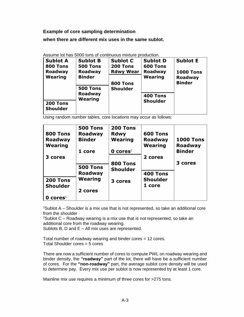
A-3
Example of core sampling determination
when there are different mix uses in the same sublot. Assume lot has 5000 tons of continuous mixture production.
Sublot A 800 Tons Roadway
Wearing
Sublot B 500 Tons Roadway
Binder
Sublot C 200 Tons Rdwy Wear
Sublot D 600 Tons Roadway
Wearing
Sublot E
1000 Tons
Roadway Binder
800 Tons Shoulder
500 Tons
Roadway Wearing
400 Tons
Shoulder 200 Tons Shoulder
Using random number tables, core locations may occur as follows:
800 Tons Roadway
Wearing
3 cores
500 Tons
Roadway Binder
1 core
200 Tons
Rdwy Wearing
0 cores2
600 Tons Roadway
Wearing
2 cores
1000 Tons
Roadway Binder
3 cores
800 Tons
Shoulder
3 cores
500 Tons
Roadway Wearing
2 cores
400 Tons
Shoulder 1 core
200 Tons Shoulder
0 cores1
1Sublot A – Shoulder is a mix use that is not represented, so take an additional core from the shoulder 2Sublot C – Roadway wearing is a mix use that is not represented, so take an additional core from the roadway wearing. Sublots B, D and E – All mix uses are represented. Total number of roadway wearing and binder cores = 12 cores. Total Shoulder cores = 5 cores There are now a sufficient number of cores to compute PWL on roadway wearing and binder density, the “roadway” part of the lot, there will have be a sufficient number of cores. For the “non-roadway” part, the average sublot core density will be used to determine pay. Every mix use per sublot is now represented by at least 1 core. Mainline mix use requires a minimum of three cores for >275 tons.

A-4

A-5
Table 502-9
Quality Index Values for Estimating Percent Within Limits (PWL)
PWL n = 3 n = 4 n = 5 - 6 n = 7 - 9 n = 10 - 12 n = 13 - 15
99 98 97 96 95 94 93 92 91 90 89 88 87 86 85 84 83 82 81 80 79 78 77 76 75 74 73 72 71 70 69 68 67 66 65 64 63 62 61 60 59 58 57 56 55 54 53 52 51 50
1.16 1.15 1.15 1.15 1.14 1.13 1.12 1.11 1.10 1.09 1.08 1.07 1.06 1.05 1.03 1.02 1.00 0.98 0.96 0.94 0.92 0.89 0.87 0.84 0.82 0.79 0.77 0.74 0.71 0.68 0.65 0.62 0.59 0.56 0.53 0.49 0.46 0.43 0.39 0.36 0.32 0.29 0.25 0.22 0.18 0.14 0.11 0.07 0.03 0.00
1.47 1.44 1.41 1.38 1.35 1.32 1.29 1.26 1.23 1.20 1.17 1.14 1.11 1.08 1.05 1.02 0.99 0.96 0.93 0.90 0.87 0.84 0.81 0.78 0.75 0.72 0.69 0.66 0.63 0.60 0.57 0.54 0.51 0.48 0.45 0.42 0.39 0.36 0.33 0.30 0.27 0.24 0.21 0.18 0.15 0.12 0.09 0.06 0.03 0.00
1.68 1.61 1.55 1.49 1.45 1.40 1.36 1.31 1.27 1.23 1.20 1.16 1.12 1.08 1.05 1.02 0.98 0.95 0.92 0.88 0.85 0.82 0.79 0.76 0.73 0.70 0.67 0.64 0.60 0.58 0.55 0.52 0.49 0.46 0.43 0.40 0.37 0.34 0.31 0.28 0.25 0.23 0.20 0.17 0.14 0.11 0.08 0.06 0.03 0.00
1.89 1.77 1.67 1.59 1.52 1.46 1.40 1.35 1.30 1.25 1.21 1.17 1.12 1.08 1.05 1.01 0.97 0.94 0.90 0.87 0.83 0.80 0.77 0.74 0.71 0.67 0.64 0.61 0.58 0.55 0.53 0.50 0.47 0.44 0.41 0.38 0.35 0.33 0.30 0.27 0.24 0.21 0.19 0.16 0.13 0.11 0.08 0.05 0.03 0.00
2.04 1.86 1.74 1.64 1.56 1.49 1.43 1.37 1.32 1.26 1.21 1.17 1.13 1.08 1.04 1.00 0.96 0.93 0.89 0.85 0.82 0.79 0.76 0.72 0.69 0.66 0.63 0.60 0.57 0.54 0.51 0.48 0.46 0.43 0.40 0.37 0.35 0.32 0.30 0.26 0.24 0.21 0.18 0.16 0.13 0.10 0.08 0.05 0.03 0.00
2.14 1.93 1.80 1.69 1.59 1.51 1.44 1.38 1.32 1.27 1.22 1.17 1.13 1.08 1.04 1.00 0.96 0.92 0.89 0.85 0.82 0.78 0.75 0.72 0.69 0.66 0.62 0.59 0.56 0.54 0.51 0.48 0.45 0.42 0.40 0.37 0.34 0.31 0.29 0.26 0.23 0.21 0.18 0.15 0.13 0.10 0.08 0.05 0.03 0.00
Note 1: For negative values of Qu or QL. PWLU or PWLL is equal to 100 minus the tabular PWLU or PWLL.
Note 2: If the value of QU or QL does not correspond exactly to a value in the table, use the next higher value.

A-6

A-7
Table 502-10 Payment Adjustment for Mainline Pavement Density
(PWL) Table A2 Percent Payment - %
Estimated
PWL
n = 3 n=4 n =
5
n =
6
n =
7
n = 8
to 9
n = 10
to 12
N =
13
n
=14
to 17
n = 18
and
greater
100 to 81 100 100 100 100 100 100 100 100 100 100
80 100 100 100 100 100 100 100 100 100 99
79 100 100 100 100 100 100 100 100 99 98
78 100 100 100 100 100 100 100 99 99 98
77 100 100 100 100 100 100 99 98 98 97
76 100 100 100 100 100 99 99 98 97 96
75 100 100 100 100 100 99 98 97 97 95
74 100 100 100 100 100 98 98 96 96 94
73 100 100 100 100 99 98 97 96 95 93
72 100 100 100 99 99 97 97 95 94 92
71 100 100 100 99 98 97 96 94 93 92
70 100 100 99 98 98 96 96 94 93 91
69 100 100 98 98 97 95 95 93 92 90
68 100 100 98 97 96 94 94 92 91 89
67 100 100 97 96 96 94 94 91 90 88
66 100 99 97 96 95 93 93 90 89 87
65 100 99 96 95 94 92 92 90 88 86
64 99 98 96 94 94 92 91 89 88 85
63 99 98 95 94 93 91 90 88 87 84
62 99 97 95 93 92 90 89 87 86 83
61 98 96 94 92 91 89 89 86 85 82
60 98 95 94 92 91 89 88 85 84 81
59 97 95 93 91 90 88 87 84 83 80
58 97 94 92 90 89 87 86 83 82 79
57 96 93 91 89 88 86 85 82 81 78
56 95 92 90 89 87 85 84 81 80 77
55 95 92 90 88 86 84 83 79 79 76
54 94 91 89 87 85 83 82 78 77 75
53 93 90 88 86 85 82 80 77 76 74
52 92 89 87 85 84 81 79 76 75 72
51 91 88 85 84 83 80 78 74 74 71
50 90 88 84 83 82 79 77 74 73 70
49 90 87 83 82 81 77 76 72 71 69
48 89 86 82 81 80 76 74 71 70 67
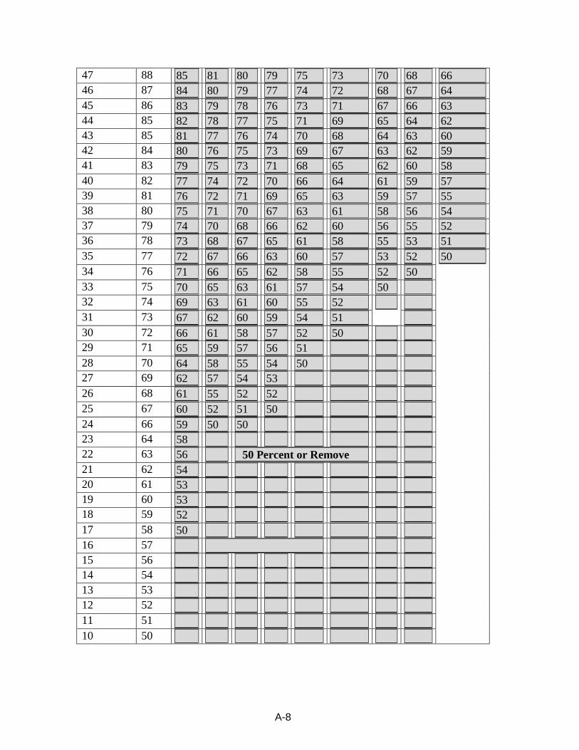
A-8
47 88 85 81 80 79 75 73 70 68 66
46 87 84 80 79 77 74 72 68 67 64
45 86 83 79 78 76 73 71 67 66 63
44 85 82 78 77 75 71 69 65 64 62
43 85 81 77 76 74 70 68 64 63 60
42 84 80 76 75 73 69 67 63 62 59
41 83 79 75 73 71 68 65 62 60 58
40 82 77 74 72 70 66 64 61 59 57
39 81 76 72 71 69 65 63 59 57 55
38 80 75 71 70 67 63 61 58 56 54
37 79 74 70 68 66 62 60 56 55 52
36 78 73 68 67 65 61 58 55 53 51
35 77 72 67 66 63 60 57 53 52 50
34 76 71 66 65 62 58 55 52 50
33 75 70 65 63 61 57 54 50
32 74 69 63 61 60 55 52
31 73 67 62 60 59 54 51
30 72 66 61 58 57 52 50
29 71 65 59 57 56 51
28 70 64 58 55 54 50
27 69 62 57 54 53
26 68 61 55 52 52
25 67 60 52 51 50
24 66 59 50 50
23 64 58
22 63 56 50 Percent or Remove
21 62 54
20 61 53
19 60 53
18 59 52
17 58 50
16 57
15 56
14 54
13 53
12 52
11 51
10 50

A-9
Generating and Using Random Numbers for Sampling Purposes
Generating random numbers for determining sampling will be covered in this section. This section is how to generate the number(s). Applying the number will be addressed in another section. The practice of riding a project and just picking a spot to choose a sample location may seem random, but statistical analysis of this has proven that a pattern emerges. There are multiple ways to utilize random numbers. One way is the use of random number tables covered here. Statistical analysis used in this specification necessitates the use of random numbers that are just that, random. The following tables have groups of numbers that are 10 across and 5 down. This grouping will be used to generate random numbers. The Inspector can generate numbers on a per lot basis or calculate the number of samples for a project and generate all the numbers for a project. Whichever method is started should be used for the whole project. One roadway lot is 5000 tons composed of five 1000-ton sublots. Each sublot is divided into three sections for acceptance core layout. Each section will have an acceptance core taken for a total of three per sublot. Each sublot will have one verification core and one resolution core taken. There are 5 (five) cores per sublot and 25 cores per lot. 25 total cores per lot 15 acceptance cores – 3 per sublot x 5 sublots 5 verification cores – 1 per sublot x 5 sublots 5 resolution cores – 1 per sublot x 5 sublots Random numbers for longitudinal distance will be 25, along with 25 random numbers for transverse distance for a total of 50 required random numbers per lot. The over and down method will be used to generate random numbers in this example. There are eight pages with seven groups of numbers per page. The Inspector can use down and then across or across and down. The selection can start left to right or right to left and then up or down depending on the starting point. The limitations are 10 horizontally and five vertically. Choose a pattern and use that pattern until all numbers are chosen or all sections are used. If more numbers are needed, pick another pattern and proceed until enough numbers are generated. On the first page, the pattern will be three down (vertical) and seven across (horizontal). In each group of 50 numbers, go down three rows and across seven columns. Going down the first page, the seven numbers generated are: 0.133, 0.954, 0.371, 0.393, 0.825, 0.416, and 0.608. The Inspector will use this pattern through the eight pages of random numbers. Once all the pages and groups are utilized, another pattern will be used to generate numbers if more are needed.
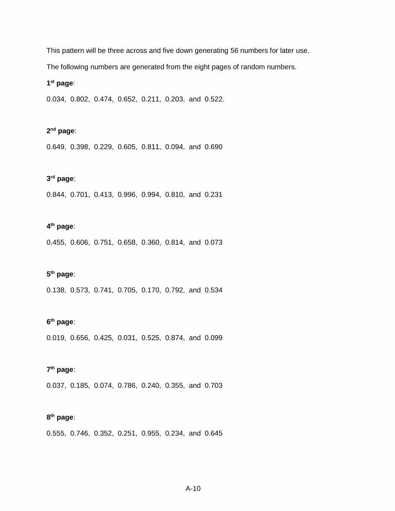
A-10
This pattern will be three across and five down generating 56 numbers for later use. The following numbers are generated from the eight pages of random numbers. 1st page:
0.034, 0.802, 0.474, 0.652, 0.211, 0.203, and 0.522.
2nd page:
0.649, 0.398, 0.229, 0.605, 0.811, 0.094, and 0.690
3rd page:
0.844, 0.701, 0.413, 0.996, 0.994, 0.810, and 0.231
4th page:
0.455, 0.606, 0.751, 0.658, 0.360, 0.814, and 0.073
5th page:
0.138, 0.573, 0.741, 0.705, 0.170, 0.792, and 0.534
6th page:
0.019, 0.656, 0.425, 0.031, 0.525, 0.874, and 0.099
7th page:
0.037, 0.185, 0.074, 0.786, 0.240, 0.355, and 0.703
8th page:
0.555, 0.746, 0.352, 0.251, 0.955, 0.234, and 0.645
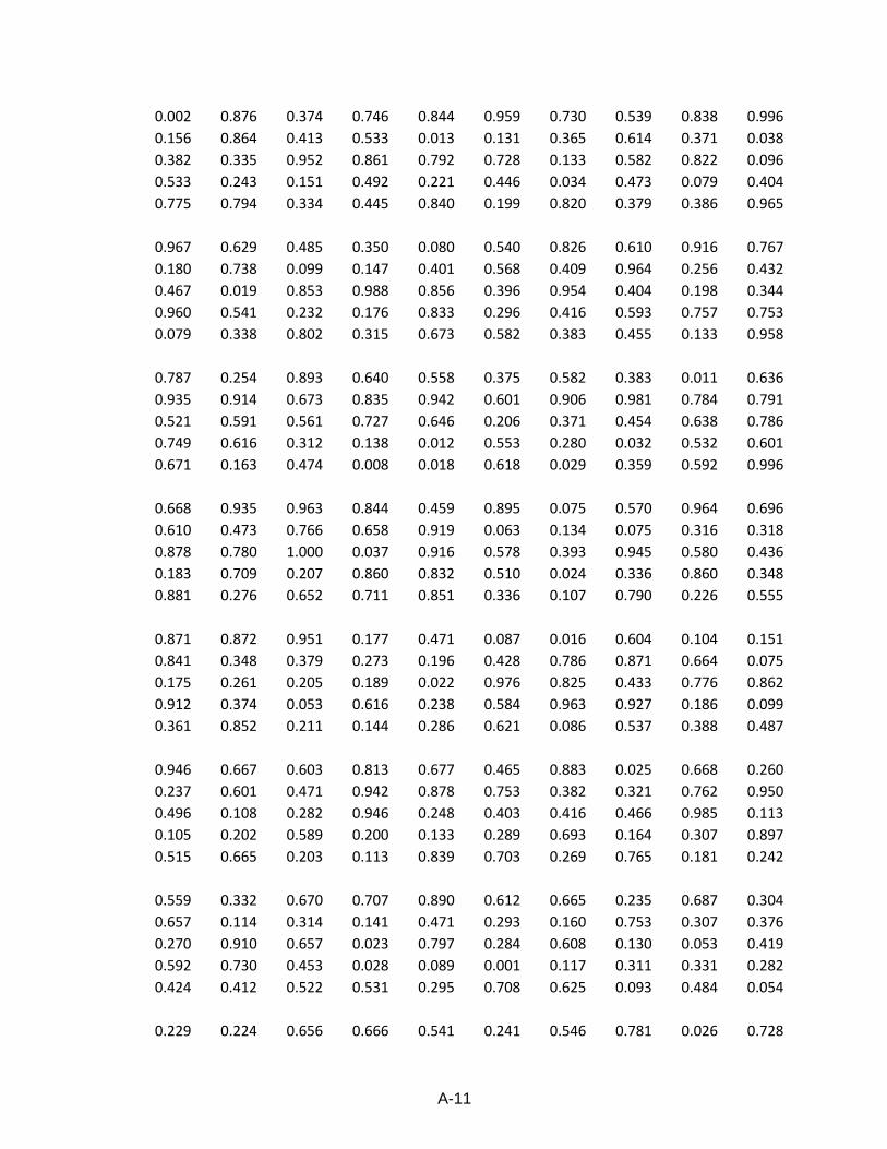
A-11
0.002 0.876 0.374 0.746 0.844 0.959 0.730 0.539 0.838 0.996
0.156 0.864 0.413 0.533 0.013 0.131 0.365 0.614 0.371 0.038
0.382 0.335 0.952 0.861 0.792 0.728 0.133 0.582 0.822 0.096
0.533 0.243 0.151 0.492 0.221 0.446 0.034 0.473 0.079 0.404
0.775 0.794 0.334 0.445 0.840 0.199 0.820 0.379 0.386 0.965
0.967 0.629 0.485 0.350 0.080 0.540 0.826 0.610 0.916 0.767
0.180 0.738 0.099 0.147 0.401 0.568 0.409 0.964 0.256 0.432
0.467 0.019 0.853 0.988 0.856 0.396 0.954 0.404 0.198 0.344
0.960 0.541 0.232 0.176 0.833 0.296 0.416 0.593 0.757 0.753
0.079 0.338 0.802 0.315 0.673 0.582 0.383 0.455 0.133 0.958
0.787 0.254 0.893 0.640 0.558 0.375 0.582 0.383 0.011 0.636
0.935 0.914 0.673 0.835 0.942 0.601 0.906 0.981 0.784 0.791
0.521 0.591 0.561 0.727 0.646 0.206 0.371 0.454 0.638 0.786
0.749 0.616 0.312 0.138 0.012 0.553 0.280 0.032 0.532 0.601
0.671 0.163 0.474 0.008 0.018 0.618 0.029 0.359 0.592 0.996
0.668 0.935 0.963 0.844 0.459 0.895 0.075 0.570 0.964 0.696
0.610 0.473 0.766 0.658 0.919 0.063 0.134 0.075 0.316 0.318
0.878 0.780 1.000 0.037 0.916 0.578 0.393 0.945 0.580 0.436
0.183 0.709 0.207 0.860 0.832 0.510 0.024 0.336 0.860 0.348
0.881 0.276 0.652 0.711 0.851 0.336 0.107 0.790 0.226 0.555
0.871 0.872 0.951 0.177 0.471 0.087 0.016 0.604 0.104 0.151
0.841 0.348 0.379 0.273 0.196 0.428 0.786 0.871 0.664 0.075
0.175 0.261 0.205 0.189 0.022 0.976 0.825 0.433 0.776 0.862
0.912 0.374 0.053 0.616 0.238 0.584 0.963 0.927 0.186 0.099
0.361 0.852 0.211 0.144 0.286 0.621 0.086 0.537 0.388 0.487
0.946 0.667 0.603 0.813 0.677 0.465 0.883 0.025 0.668 0.260
0.237 0.601 0.471 0.942 0.878 0.753 0.382 0.321 0.762 0.950
0.496 0.108 0.282 0.946 0.248 0.403 0.416 0.466 0.985 0.113
0.105 0.202 0.589 0.200 0.133 0.289 0.693 0.164 0.307 0.897
0.515 0.665 0.203 0.113 0.839 0.703 0.269 0.765 0.181 0.242
0.559 0.332 0.670 0.707 0.890 0.612 0.665 0.235 0.687 0.304
0.657 0.114 0.314 0.141 0.471 0.293 0.160 0.753 0.307 0.376
0.270 0.910 0.657 0.023 0.797 0.284 0.608 0.130 0.053 0.419
0.592 0.730 0.453 0.028 0.089 0.001 0.117 0.311 0.331 0.282
0.424 0.412 0.522 0.531 0.295 0.708 0.625 0.093 0.484 0.054
0.229 0.224 0.656 0.666 0.541 0.241 0.546 0.781 0.026 0.728
A-12
0.967 0.759 0.724 0.702 0.947 0.777 0.791 0.129 0.796 0.782
0.272 0.718 0.356 0.847 0.657 0.383 0.238 0.590 0.241 0.284
0.313 0.818 0.822 0.862 0.253 0.047 0.772 0.758 0.384 0.052
0.997 0.034 0.649 0.113 0.847 0.602 0.952 0.097 0.470 0.260
0.672 0.051 0.670 0.247 0.622 0.449 0.794 0.722 0.235 0.756
0.665 0.076 0.260 0.456 0.110 0.474 0.758 0.216 0.108 0.544
0.651 0.328 0.084 0.615 0.648 0.090 0.385 0.410 0.784 0.288
0.474 0.594 0.393 0.419 0.862 0.104 0.764 0.838 0.322 0.633
0.286 0.455 0.398 0.214 0.346 0.158 0.770 0.276 0.771 0.618
0.468 0.100 0.093 0.618 0.502 0.071 0.416 0.580 0.917 0.633
0.167 0.431 0.810 0.364 0.514 0.473 0.344 0.056 0.732 0.416
0.286 0.229 0.299 0.216 0.101 0.971 0.996 0.896 0.136 0.516
0.801 0.978 0.922 0.460 0.863 0.716 0.125 0.031 0.315 0.754
0.181 0.314 0.229 0.389 0.141 0.831 0.495 0.079 0.766 0.401
0.882 0.365 0.388 0.656 0.086 0.853 0.586 0.155 0.042 0.423
0.199 0.472 0.263 0.304 0.700 0.186 0.520 0.194 0.483 0.157
0.608 0.065 0.069 0.022 0.506 0.806 0.785 0.291 0.705 0.385
0.934 0.969 0.975 0.649 0.985 0.091 0.367 0.458 0.826 0.101
0.723 0.274 0.605 0.455 0.477 0.884 0.187 0.373 0.029 0.409
0.760 0.141 0.469 0.245 0.629 0.861 0.940 0.107 0.717 0.069
0.417 0.819 0.813 0.120 0.179 0.014 0.091 0.743 0.765 0.405
0.947 0.678 0.683 0.764 0.658 0.804 0.670 0.287 0.924 0.648
0.761 0.494 0.800 0.708 0.975 0.310 0.069 0.464 0.878 0.498
0.569 0.521 0.811 0.092 0.520 0.746 0.070 0.987 0.377 0.850
0.813 0.350 0.233 0.287 0.975 0.990 0.317 0.893 0.974 0.365
0.609 0.169 0.493 0.369 0.101 0.611 0.112 0.557 0.749 0.998
0.075 0.967 0.626 0.035 0.973 0.195 0.333 0.270 0.628 0.876
0.168 0.684 0.949 0.230 0.123 0.858 0.055 0.831 0.197 0.125
0.429 0.249 0.094 0.623 0.410 0.731 0.817 0.639 0.771 0.561
0.186 0.158 0.691 0.282 0.834 0.030 0.896 0.401 0.682 0.647
0.240 0.768 0.449 0.547 0.517 0.262 0.214 0.852 0.786 0.945
0.570 0.934 0.982 0.353 0.392 0.231 0.102 0.059 0.758 0.608
0.747 0.183 0.056 0.173 0.292 0.994 0.791 0.958 0.478 0.264
0.156 0.362 0.698 0.536 0.856 0.772 0.766 0.946 0.257 0.264
0.438 0.774 0.364 0.788 0.482 0.372 0.666 0.745 0.565 0.616
0.393 0.367 0.746 0.562 0.187 0.801 0.852 0.433 0.755 0.299
A-13
0.524 0.619 0.499 0.432 0.203 0.830 0.686 0.723 0.854 0.062
0.162 0.619 0.688 0.540 0.163 0.182 0.689 0.280 0.241 0.445
0.201 0.443 0.844 0.797 0.376 0.119 0.568 0.333 0.750 0.713
0.637 0.567 0.746 0.583 0.613 0.404 0.361 0.083 0.890 0.797
0.842 0.673 0.992 0.971 0.617 0.245 0.207 0.647 0.267 0.336
0.595 0.148 0.820 0.364 0.890 0.808 0.153 0.556 0.341 0.590
0.771 0.727 0.006 0.305 0.760 0.553 0.553 0.360 0.182 0.510
0.076 0.419 0.701 0.120 0.969 0.909 0.715 0.674 0.394 0.741
0.786 0.078 0.363 0.196 0.637 0.983 0.969 0.344 0.499 0.858
0.804 0.926 0.106 0.150 0.087 0.090 0.091 0.209 0.534 0.908
0.086 0.106 0.507 0.050 0.305 0.029 0.470 0.550 0.876 0.393
0.276 0.055 0.724 0.325 0.336 0.467 0.272 0.687 0.170 0.378
0.743 0.288 0.413 0.223 0.355 0.439 0.760 0.528 0.168 0.510
0.923 0.191 0.897 0.647 0.104 0.176 0.435 0.305 0.028 0.544
0.400 0.749 0.063 0.213 0.463 0.177 0.461 0.368 0.753 0.642
0.244 0.916 0.120 0.394 0.780 0.897 0.520 0.831 0.564 0.256
0.328 0.697 0.248 0.882 0.845 0.691 0.443 0.321 0.781 0.135
0.333 0.073 0.996 0.869 0.620 0.867 0.292 0.018 0.843 0.837
0.515 0.798 0.594 0.993 0.770 0.002 0.673 0.896 0.012 0.345
0.692 0.945 0.813 0.295 0.189 0.185 0.568 0.578 0.757 0.036
0.934 0.987 0.232 0.848 0.777 0.663 0.469 0.702 0.407 0.511
0.741 0.346 0.398 0.883 0.282 0.678 0.740 0.222 0.015 0.696
0.648 0.780 0.994 0.293 0.772 0.106 0.586 0.836 0.109 0.427
0.935 0.903 0.397 0.609 0.725 0.113 0.262 0.823 0.787 0.435
0.911 0.599 0.572 0.894 0.647 0.410 0.024 0.069 0.984 0.442
0.887 0.306 0.651 0.719 0.975 0.034 0.259 0.215 0.432 0.102
0.917 0.141 0.521 0.538 0.575 0.033 0.972 0.642 0.377 0.819
0.410 0.813 0.810 0.509 0.908 0.014 0.915 0.669 0.193 0.296
0.361 0.335 0.525 0.268 0.650 0.523 0.798 0.930 0.237 0.990
0.878 0.780 0.848 0.402 0.718 0.586 0.780 0.570 0.288 0.742
0.456 0.905 0.827 0.613 0.020 0.748 0.478 0.771 0.261 0.735
0.819 0.522 0.638 0.853 0.323 0.652 0.680 0.337 0.283 0.776
0.571 0.078 0.231 0.201 0.164 0.674 0.383 0.724 0.233 0.814
0.143 0.249 0.236 0.116 0.185 0.647 0.360 0.104 0.167 0.758
0.151 0.462 0.589 0.937 0.485 0.228 0.829 0.062 0.183 0.086
0.903 0.396 0.037 0.408 0.953 0.224 0.533 0.203 0.030 0.660
A-14
0.058 0.638 0.164 0.532 0.862 0.267 0.287 0.755 0.558 0.648
0.016 0.103 0.455 0.487 0.843 0.767 0.483 0.977 0.749 0.631
0.007 0.476 0.789 0.647 0.313 0.189 0.666 0.242 0.029 0.016
0.829 0.135 0.287 0.198 0.135 0.490 0.885 0.955 0.592 0.810
0.247 0.728 0.223 0.462 0.452 0.226 0.581 0.267 0.115 0.896
0.944 0.024 0.407 0.994 0.730 0.418 0.987 0.915 0.143 0.178
0.134 0.919 0.606 0.918 0.857 0.931 0.996 0.555 0.262 0.558
0.217 0.714 0.966 0.979 0.141 0.025 0.824 0.879 0.456 0.722
0.772 0.060 0.433 0.439 0.041 0.909 0.169 0.627 0.550 0.356
0.318 0.486 0.734 0.503 0.845 0.812 0.612 0.555 0.843 0.689
0.358 0.235 0.932 0.403 0.160 0.312 0.281 0.512 0.663 0.424
0.780 0.450 0.751 0.831 0.388 0.602 0.978 0.272 0.205 0.226
0.401 0.568 0.277 0.151 0.122 0.137 0.683 0.650 0.304 0.069
0.927 0.384 0.941 0.928 0.166 0.843 0.182 0.924 0.309 0.173
0.463 0.623 0.519 0.801 0.256 0.846 0.141 0.773 0.689 0.913
0.595 0.195 0.845 0.885 0.266 0.691 0.999 0.974 0.917 0.296
0.587 0.754 0.658 0.666 0.188 0.358 0.002 0.032 0.289 0.288
0.047 0.791 0.129 0.018 0.298 0.154 0.396 0.028 0.178 0.743
0.055 0.445 0.751 0.547 0.094 0.924 0.685 0.153 0.469 0.945
0.997 0.647 0.026 0.171 0.599 0.091 0.681 0.029 0.182 0.997
0.646 0.164 0.474 0.680 0.969 0.932 0.394 0.922 0.188 0.579
0.141 0.833 0.360 0.262 0.741 0.327 0.264 0.583 0.091 0.118
0.044 0.766 0.032 0.629 0.088 0.164 0.472 0.746 0.409 0.224
0.102 0.799 0.323 0.588 0.725 0.685 0.698 0.471 0.746 0.545
0.552 0.982 0.831 0.895 0.296 0.540 0.291 0.611 0.380 0.040
0.197 0.694 0.644 0.932 0.785 0.200 0.150 0.856 0.155 0.249
0.766 0.010 0.814 0.528 0.297 0.881 0.091 0.181 0.436 0.520
0.943 0.499 0.319 0.002 0.202 0.313 0.962 0.233 0.781 0.504
0.371 0.756 0.873 0.526 0.591 0.718 0.677 0.350 0.492 0.654
0.680 0.749 0.553 0.233 0.029 0.308 0.452 0.643 0.020 0.078
0.713 0.746 0.235 0.288 0.221 0.686 0.366 0.003 0.860 0.081
0.250 0.146 0.073 0.472 0.144 0.784 0.618 0.184 0.783 0.100
0.303 0.243 0.237 0.929 0.978 0.522 0.112 0.290 0.576 0.756
0.116 0.812 0.462 0.598 0.526 0.449 0.901 0.361 0.590 0.412
0.903 0.601 0.389 0.704 0.230 0.211 0.192 0.175 0.861 0.168
0.836 0.502 0.676 0.593 0.172 0.999 0.654 0.286 0.084 0.662
A-15
0.364 0.384 0.138 0.355 0.022 0.306 0.377 0.550 0.905 0.635
0.300 0.517 0.405 0.093 0.551 0.380 0.489 0.277 0.355 0.932
0.863 0.290 0.226 0.638 0.612 0.952 0.988 0.704 0.602 0.715
0.624 0.637 0.420 0.971 0.003 0.207 0.140 0.881 0.005 0.189
0.687 0.399 0.074 0.828 0.091 0.640 0.740 0.405 0.406 0.255
0.127 0.824 0.573 0.953 0.998 0.624 0.017 0.850 0.342 0.317
0.246 0.782 0.065 0.465 0.251 0.244 0.783 0.401 0.969 0.115
0.283 0.996 0.606 0.823 0.650 0.383 0.089 0.103 0.618 0.042
0.441 0.011 0.160 0.149 0.348 0.338 0.852 0.606 0.703 0.100
0.050 0.645 0.419 0.240 0.398 0.423 0.271 0.208 0.707 0.500
0.068 0.581 0.741 0.633 0.928 0.360 0.920 0.756 0.935 0.127
0.505 0.585 0.963 0.694 0.260 0.735 0.949 0.411 0.148 0.759
0.391 0.795 0.083 0.026 0.360 0.623 0.270 0.821 0.800 0.154
0.161 0.600 0.401 0.634 0.564 0.793 0.825 0.743 0.934 0.049
0.570 0.136 0.376 0.360 0.245 0.731 0.390 0.943 0.545 0.916
0.897 0.293 0.705 0.309 0.567 0.327 0.714 0.247 0.984 1.000
0.066 0.649 0.685 0.327 0.340 0.410 0.595 0.199 0.376 0.988
0.897 0.895 0.342 0.337 0.860 0.724 0.466 0.834 0.669 0.665
0.709 0.380 0.772 0.447 0.176 0.297 0.786 0.948 0.531 0.209
0.499 0.332 0.202 0.545 0.977 0.839 0.663 0.827 0.332 0.606
0.565 0.391 0.170 0.461 0.006 0.717 0.247 0.064 0.713 0.994
0.374 0.325 0.423 0.111 0.097 0.492 0.243 0.696 0.180 0.819
0.269 0.387 0.430 0.222 0.246 0.974 0.890 0.823 0.553 0.582
0.929 0.801 0.283 0.529 0.271 0.442 0.722 0.044 0.479 0.799
0.979 0.484 0.936 0.876 0.074 0.198 0.857 0.730 0.250 0.724
0.345 0.404 0.792 0.440 0.050 0.103 0.146 0.350 0.435 0.500
0.600 0.156 0.198 0.602 0.327 0.260 0.875 0.066 0.056 0.870
0.156 0.380 0.162 0.857 0.944 0.804 0.455 0.512 0.689 0.493
0.445 0.881 0.033 0.696 0.368 0.809 0.286 0.442 0.751 0.367
0.778 0.621 0.802 0.809 0.605 0.857 0.401 0.725 0.811 0.094
0.982 0.526 0.534 0.290 0.067 0.948 0.140 0.127 0.765 0.703
0.889 0.147 0.987 0.946 0.152 0.219 0.675 0.716 0.723 0.737
0.821 1.000 0.242 0.469 0.559 0.585 0.273 0.446 0.115 0.344
0.067 0.814 0.878 0.123 0.527 0.039 0.405 0.875 0.428 0.391
0.610 0.206 0.408 0.087 0.938 0.983 0.767 0.029 0.794 0.164
0.600 0.516 0.019 0.507 0.304 0.857 0.682 0.305 0.983 0.281

A-16
0.983 0.821 0.785 0.048 0.530 0.556 0.701 0.174 0.794 0.035
0.862 0.677 0.003 0.233 0.854 0.741 0.267 0.333 0.099 0.713
0.214 0.938 0.815 0.338 0.917 0.426 0.601 0.131 0.386 0.576
0.169 0.305 0.428 0.138 0.263 0.149 0.129 0.500 0.282 0.269
0.757 0.106 0.656 0.595 0.360 0.781 0.491 0.566 0.849 0.621
0.526 0.390 0.830 0.604 0.921 0.794 0.990 0.578 0.923 0.166
0.291 0.783 0.925 0.491 0.779 0.561 0.958 0.002 0.274 0.411
0.152 0.931 0.724 0.050 0.181 0.287 0.507 0.626 0.240 0.052
0.465 0.752 0.580 0.709 0.943 0.507 0.127 0.508 0.623 0.061
0.218 0.370 0.425 0.093 0.997 0.845 0.270 0.635 0.482 0.020
0.969 0.526 0.848 0.797 0.032 0.107 0.960 0.425 0.675 0.326
0.675 0.719 0.804 0.914 0.952 0.852 0.260 0.777 0.297 0.132
0.104 0.260 0.590 0.682 0.223 0.454 0.792 0.402 0.043 0.189
0.600 0.152 0.624 0.865 0.562 0.538 0.922 0.800 0.677 0.215
0.499 0.219 0.031 0.121 0.459 0.574 0.486 0.530 0.894 0.322
0.956 0.352 0.629 0.836 0.299 0.572 0.523 0.597 0.369 0.231
0.143 0.330 0.239 0.875 0.055 0.228 0.146 0.853 0.545 0.933
0.169 0.392 0.025 0.427 0.196 0.839 0.930 0.482 0.187 0.986
0.366 0.834 0.279 0.883 0.299 0.735 0.760 0.040 0.573 0.033
0.445 0.430 0.525 0.449 0.478 0.197 0.486 0.195 0.104 0.475
0.953 0.591 0.431 0.223 0.700 0.851 0.715 0.489 0.625 0.668
0.211 0.997 0.601 0.785 0.101 0.473 0.124 0.182 0.547 0.620
0.025 0.053 0.395 0.130 0.048 0.217 0.554 0.659 0.546 0.129
0.601 0.165 0.109 0.142 0.613 0.506 0.381 0.173 0.790 0.716
0.855 0.443 0.874 0.866 0.932 0.427 0.913 0.900 0.016 0.685
0.389 0.375 0.939 0.731 0.246 0.491 0.478 0.586 0.860 0.333
0.270 0.175 0.453 0.719 0.881 0.232 0.022 0.569 0.330 0.859
0.278 0.198 0.841 0.402 0.647 0.432 0.097 0.795 0.862 0.975
0.797 0.031 0.169 0.900 0.778 0.923 0.686 0.707 0.487 0.790
0.944 0.821 0.099 0.257 0.136 0.962 0.041 0.790 0.122 0.275
0.215 0.152 0.693 0.642 0.706 0.418 0.156 0.064 0.241 0.704
0.750 0.537 0.194 0.292 0.930 0.322 0.414 0.263 0.057 0.001
0.654 0.344 0.512 0.258 0.883 0.081 0.782 0.750 0.270 0.027
0.531 0.014 0.110 0.081 0.205 0.788 0.483 0.646 0.186 0.659
0.914 0.753 0.037 0.461 0.839 0.816 0.869 0.297 0.126 0.169

A-17
0.356 0.629 0.463 0.043 0.425 0.308 0.874 0.135 0.176 0.971
0.154 0.434 0.026 0.710 0.497 0.452 0.642 0.407 0.109 0.523
0.675 0.651 0.075 0.317 0.838 0.648 0.272 0.236 0.340 0.015
0.596 0.840 0.238 0.877 0.305 0.966 0.703 0.168 0.733 0.688
0.764 0.545 0.185 0.784 0.538 0.817 0.261 0.855 0.484 0.300
0.428 0.769 0.721 1.000 0.087 0.559 0.925 0.034 0.938 0.466
0.853 0.195 0.915 0.256 0.013 0.062 0.477 0.471 0.517 0.567
0.528 0.790 0.645 0.423 0.762 0.130 0.155 0.321 0.697 0.661
0.872 0.302 0.191 0.380 0.575 0.200 0.720 0.417 0.726 0.585
0.190 0.701 0.074 0.089 0.580 0.176 0.650 0.534 0.182 0.197
0.199 0.762 0.730 0.272 0.574 0.584 0.190 0.809 0.123 0.739
0.503 0.020 0.601 0.276 0.054 0.639 0.645 0.275 0.149 0.613
0.325 0.298 0.285 0.415 0.825 0.479 0.492 0.145 0.771 0.672
0.531 0.067 0.236 0.545 0.219 0.747 0.965 0.044 0.680 0.436
0.840 0.117 0.786 0.866 0.122 0.118 0.580 0.107 0.496 0.783
0.957 0.652 0.462 0.203 0.387 0.367 0.086 0.679 0.961 0.484
0.656 0.888 0.538 0.282 0.270 0.236 0.280 0.608 0.886 0.845
0.349 0.909 0.865 0.037 0.057 0.912 0.542 0.756 0.237 0.627
0.850 0.809 0.132 0.817 0.535 0.357 0.567 0.594 0.991 0.534
0.702 0.299 0.240 0.624 0.127 0.325 0.100 0.689 0.605 0.031
0.062 0.064 0.222 0.407 0.911 0.609 0.235 0.655 0.626 0.147
0.402 0.324 0.583 0.973 0.069 0.174 0.596 0.854 0.803 0.416
0.832 0.420 0.835 0.476 0.116 0.355 0.125 0.963 0.682 0.288
0.293 0.972 0.873 0.806 0.228 0.391 0.846 0.474 0.644 0.370
0.793 0.281 0.355 0.602 0.729 0.423 0.570 0.570 0.355 0.815
0.976 0.434 0.056 0.245 0.890 0.682 0.532 0.585 0.267 0.241
0.127 0.948 0.846 0.168 0.358 0.211 0.204 0.601 0.697 0.805
0.015 0.116 0.121 0.179 0.284 0.148 0.477 0.841 0.841 0.634
0.177 0.393 0.876 0.529 0.266 0.447 0.799 0.365 0.392 0.851
0.194 0.486 0.703 0.115 0.176 0.138 0.210 0.447 0.891 0.061
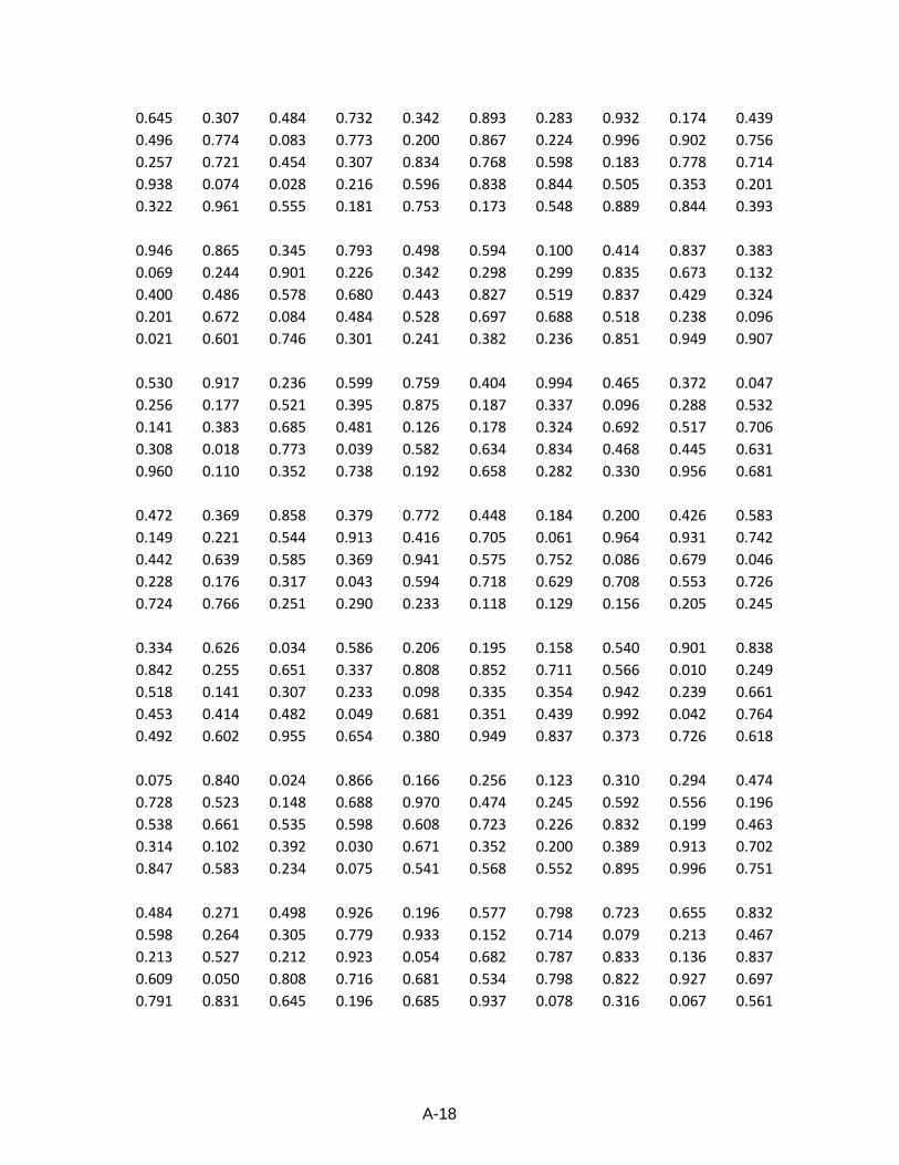
A-18
0.645 0.307 0.484 0.732 0.342 0.893 0.283 0.932 0.174 0.439
0.496 0.774 0.083 0.773 0.200 0.867 0.224 0.996 0.902 0.756
0.257 0.721 0.454 0.307 0.834 0.768 0.598 0.183 0.778 0.714
0.938 0.074 0.028 0.216 0.596 0.838 0.844 0.505 0.353 0.201
0.322 0.961 0.555 0.181 0.753 0.173 0.548 0.889 0.844 0.393
0.946 0.865 0.345 0.793 0.498 0.594 0.100 0.414 0.837 0.383
0.069 0.244 0.901 0.226 0.342 0.298 0.299 0.835 0.673 0.132
0.400 0.486 0.578 0.680 0.443 0.827 0.519 0.837 0.429 0.324
0.201 0.672 0.084 0.484 0.528 0.697 0.688 0.518 0.238 0.096
0.021 0.601 0.746 0.301 0.241 0.382 0.236 0.851 0.949 0.907
0.530 0.917 0.236 0.599 0.759 0.404 0.994 0.465 0.372 0.047
0.256 0.177 0.521 0.395 0.875 0.187 0.337 0.096 0.288 0.532
0.141 0.383 0.685 0.481 0.126 0.178 0.324 0.692 0.517 0.706
0.308 0.018 0.773 0.039 0.582 0.634 0.834 0.468 0.445 0.631
0.960 0.110 0.352 0.738 0.192 0.658 0.282 0.330 0.956 0.681
0.472 0.369 0.858 0.379 0.772 0.448 0.184 0.200 0.426 0.583
0.149 0.221 0.544 0.913 0.416 0.705 0.061 0.964 0.931 0.742
0.442 0.639 0.585 0.369 0.941 0.575 0.752 0.086 0.679 0.046
0.228 0.176 0.317 0.043 0.594 0.718 0.629 0.708 0.553 0.726
0.724 0.766 0.251 0.290 0.233 0.118 0.129 0.156 0.205 0.245
0.334 0.626 0.034 0.586 0.206 0.195 0.158 0.540 0.901 0.838
0.842 0.255 0.651 0.337 0.808 0.852 0.711 0.566 0.010 0.249
0.518 0.141 0.307 0.233 0.098 0.335 0.354 0.942 0.239 0.661
0.453 0.414 0.482 0.049 0.681 0.351 0.439 0.992 0.042 0.764
0.492 0.602 0.955 0.654 0.380 0.949 0.837 0.373 0.726 0.618
0.075 0.840 0.024 0.866 0.166 0.256 0.123 0.310 0.294 0.474
0.728 0.523 0.148 0.688 0.970 0.474 0.245 0.592 0.556 0.196
0.538 0.661 0.535 0.598 0.608 0.723 0.226 0.832 0.199 0.463
0.314 0.102 0.392 0.030 0.671 0.352 0.200 0.389 0.913 0.702
0.847 0.583 0.234 0.075 0.541 0.568 0.552 0.895 0.996 0.751
0.484 0.271 0.498 0.926 0.196 0.577 0.798 0.723 0.655 0.832
0.598 0.264 0.305 0.779 0.933 0.152 0.714 0.079 0.213 0.467
0.213 0.527 0.212 0.923 0.054 0.682 0.787 0.833 0.136 0.837
0.609 0.050 0.808 0.716 0.681 0.534 0.798 0.822 0.927 0.697
0.791 0.831 0.645 0.196 0.685 0.937 0.078 0.316 0.067 0.561
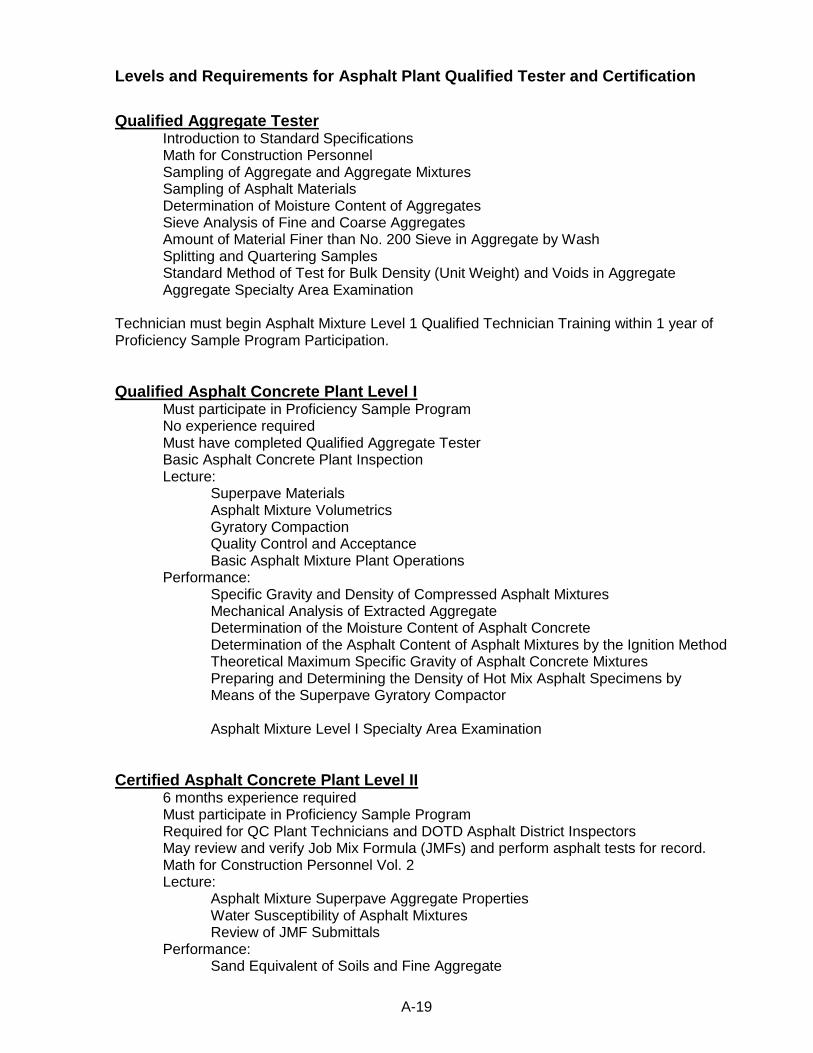
A-19
Levels and Requirements for Asphalt Plant Qualified Tester and Certification
Qualified Aggregate Tester Introduction to Standard Specifications Math for Construction Personnel Sampling of Aggregate and Aggregate Mixtures Sampling of Asphalt Materials Determination of Moisture Content of Aggregates Sieve Analysis of Fine and Coarse Aggregates Amount of Material Finer than No. 200 Sieve in Aggregate by Wash Splitting and Quartering Samples Standard Method of Test for Bulk Density (Unit Weight) and Voids in Aggregate Aggregate Specialty Area Examination Technician must begin Asphalt Mixture Level 1 Qualified Technician Training within 1 year of Proficiency Sample Program Participation.
Qualified Asphalt Concrete Plant Level I Must participate in Proficiency Sample Program No experience required Must have completed Qualified Aggregate Tester Basic Asphalt Concrete Plant Inspection Lecture: Superpave Materials Asphalt Mixture Volumetrics Gyratory Compaction Quality Control and Acceptance Basic Asphalt Mixture Plant Operations Performance: Specific Gravity and Density of Compressed Asphalt Mixtures Mechanical Analysis of Extracted Aggregate Determination of the Moisture Content of Asphalt Concrete Determination of the Asphalt Content of Asphalt Mixtures by the Ignition Method Theoretical Maximum Specific Gravity of Asphalt Concrete Mixtures
Preparing and Determining the Density of Hot Mix Asphalt Specimens by Means of the Superpave Gyratory Compactor
Asphalt Mixture Level I Specialty Area Examination
Certified Asphalt Concrete Plant Level II 6 months experience required Must participate in Proficiency Sample Program Required for QC Plant Technicians and DOTD Asphalt District Inspectors May review and verify Job Mix Formula (JMFs) and perform asphalt tests for record. Math for Construction Personnel Vol. 2 Lecture: Asphalt Mixture Superpave Aggregate Properties Water Susceptibility of Asphalt Mixtures Review of JMF Submittals
Performance: Sand Equivalent of Soils and Fine Aggregate
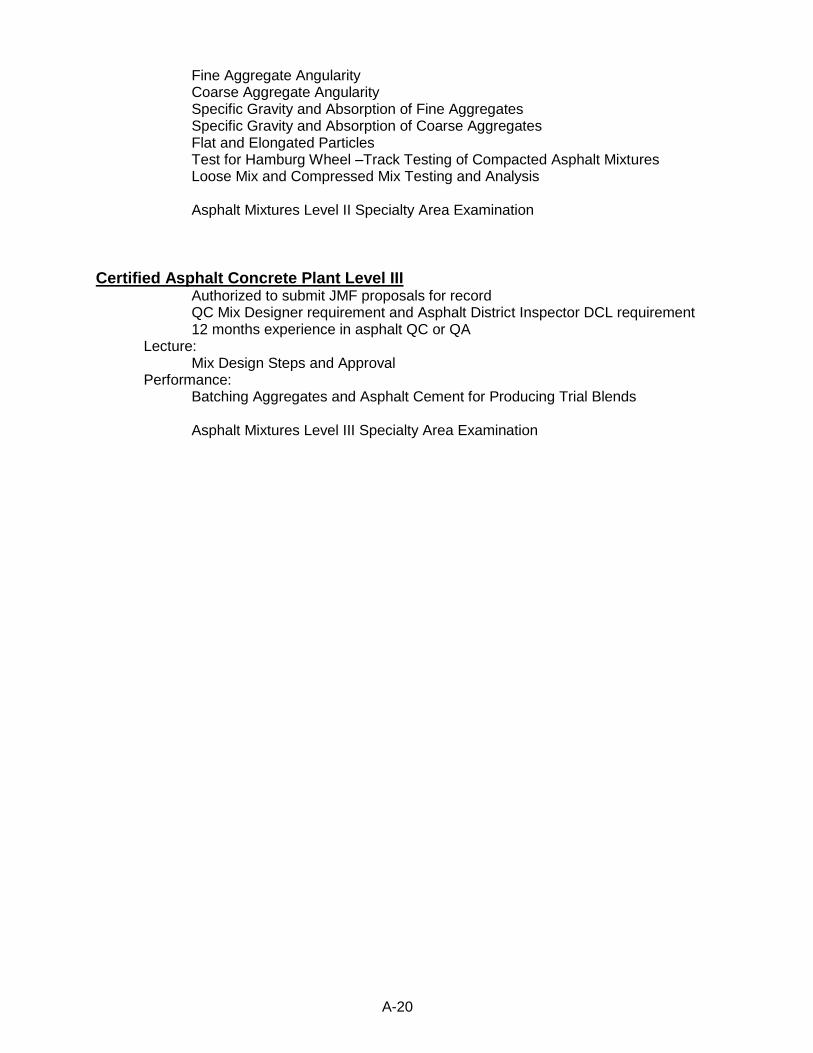
A-20
Fine Aggregate Angularity Coarse Aggregate Angularity Specific Gravity and Absorption of Fine Aggregates Specific Gravity and Absorption of Coarse Aggregates Flat and Elongated Particles Test for Hamburg Wheel –Track Testing of Compacted Asphalt Mixtures Loose Mix and Compressed Mix Testing and Analysis Asphalt Mixtures Level II Specialty Area Examination
Certified Asphalt Concrete Plant Level III Authorized to submit JMF proposals for record QC Mix Designer requirement and Asphalt District Inspector DCL requirement 12 months experience in asphalt QC or QA Lecture: Mix Design Steps and Approval Performance: Batching Aggregates and Asphalt Cement for Producing Trial Blends Asphalt Mixtures Level III Specialty Area Examination
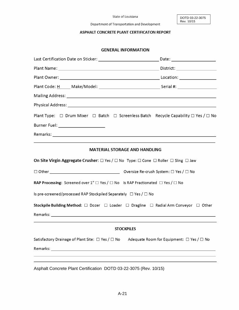
A-21
Asphalt Concrete Plant Certification DOTD 03-22-3075 (Rev. 10/15)
DOTD 03-22-3075 Rev. 10/15

A-22
DOTD 03-22-3075 Rev. 10/15 Page 1 of 8
Material Approved
Source Satisfactory
Drainage Separation
Contamination Segregation Adequate Spacing Partition
Yes No Yes No Yes No Yes No Yes No Yes No Yes No
COLD AGGREGATE FEEDER
Virgin Aggregate Recycled Material
Type of loading…………………………………………………………□ Front End Loader □ Front End Loader
□ Other □ Other
Number of Cold Feed Systems Used…………………………………
If more than one system is used, are they integrated?.... □ Yes / □ No □ Yes / □ No
Number of Cold Bins Used……………………………………………………………
Number of bins sufficient for operations…………………………………… □ Yes / □ No □ Yes / □ No
Bins are large enough for continuous operation at rated capacity□ Yes / □ No □ Yes / □ No
Condition of bins satisfactory……………………………………………………..□ Yes / □ No □ Yes / □ No
Partitions extend a minimum one foot above top between bins □ Yes / □ No □ Yes / □ No
Bins equipped with vibrators………………………………………………………□ Yes / □ No □ Yes / □ No
Individual Bin Gates:
Gate rectangular……………………………………..…………………… □ Yes / □ No □ Yes / □ No
Positive mechanical adjustment………………………….…….…..□ Yes / □ No □ Yes / □ No
Locks in position…………………………………………………………….□ Yes / □ No □ Yes / □ No
Aggregate Proportioning by cold feed………………………………..□ Applicable □ N/A □ Applicable □ N/A
Determined by……………………………………………………...□ Belt Speed □ Gate Opening
Calib. Curve / each bin per material type used……………… □ Yes / □ No □ Yes / □ No
Automatic shut off on each bin……………………………………. □ Yes / □ No □ Yes / □ No
Adjusted and operating correctly…………………………………..□ Yes / □ No □ Yes / □ No
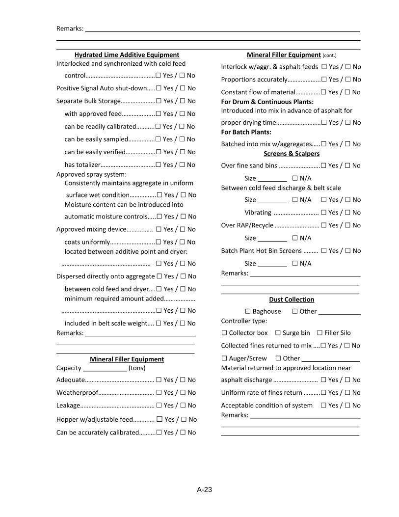
A-23
DOTD 03-22-3075 Rev. 10/15 Page 1 of 8
Remarks:
Hydrated Lime Additive Equipment Interlocked and synchronized with cold feed
control……………………………………□ Yes / □ No
Positive Signal Auto shut-down…..□ Yes / □ No
Separate Bulk Storage…………………□ Yes / □ No
with approved feed………………..□ Yes / □ No
can be readily calibrated………..□ Yes / □ No
can be easily sampled…………….□ Yes / □ No
can be easily verified………………□ Yes / □ No
has totalizer……………………………□ Yes / □ No
Approved spray system: Consistently maintains aggregate in uniform
surface wet condition…………….□ Yes / □ No
Moisture content can be introduced into
automatic moisture controls…..□ Yes / □ No
Approved mixing device……………. □ Yes / □ No
coats uniformly…………….………..□ Yes / □ No
located between additive point and dryer:
……………………………………………… □ Yes / □ No
Dispersed directly onto aggregate □ Yes / □ No
between cold feed and dryer….□ Yes / □ No
minimum required amount added……………….
…………………………………………………□ Yes / □ No
included in belt scale weight…. □ Yes / □ No
Remarks:
Mineral Filler Equipment Capacity (tons)
Adequate…………………………………… □ Yes / □ No
Weatherproof……………………………. □ Yes / □ No
Leakage……………………………………… □ Yes / □ No
Hopper w/adjustable feed…………. □ Yes / □ No
Can be accurately calibrated……….□ Yes / □ No
Mineral Filler Equipment (cont.)
Interlock w/aggr. & asphalt feeds □ Yes / □ No
Proportions accurately………………..□ Yes / □ No
Constant flow of material……………□ Yes / □ No
For Drum & Continuous Plants: Introduced into mix in advance of asphalt for
proper drying time………………………□ Yes / □ No
For Batch Plants:
Batched into mix w/aggregates…..□ Yes / □ No
Screens & Scalpers
Over fine sand bins …………………….□ Yes / □ No
Size □ N/A
Between cold feed discharge & belt scale
Size □ N/A □ Yes / □ No
Vibrating .…………………….. □ Yes / □ No
Over RAP/Recycle ……………………… □ Yes / □ No
Size □ N/A
Batch Plant Hot Bin Screens ……… □ Yes / □ No
Size □ N/A
Remarks:
Dust Collection
□ Baghouse □ Other
Controller type:
□ Collector box □ Surge bin □ Filler Silo
Collected fines returned to mix ….□ Yes / □ No
□ Auger/Screw □ Other
Material returned to approved location near
asphalt discharge ……………………… □ Yes / □ No
Uniform rate of fines return ……….□ Yes / □ No
Acceptable condition of system □ Yes / □ No
Remarks:
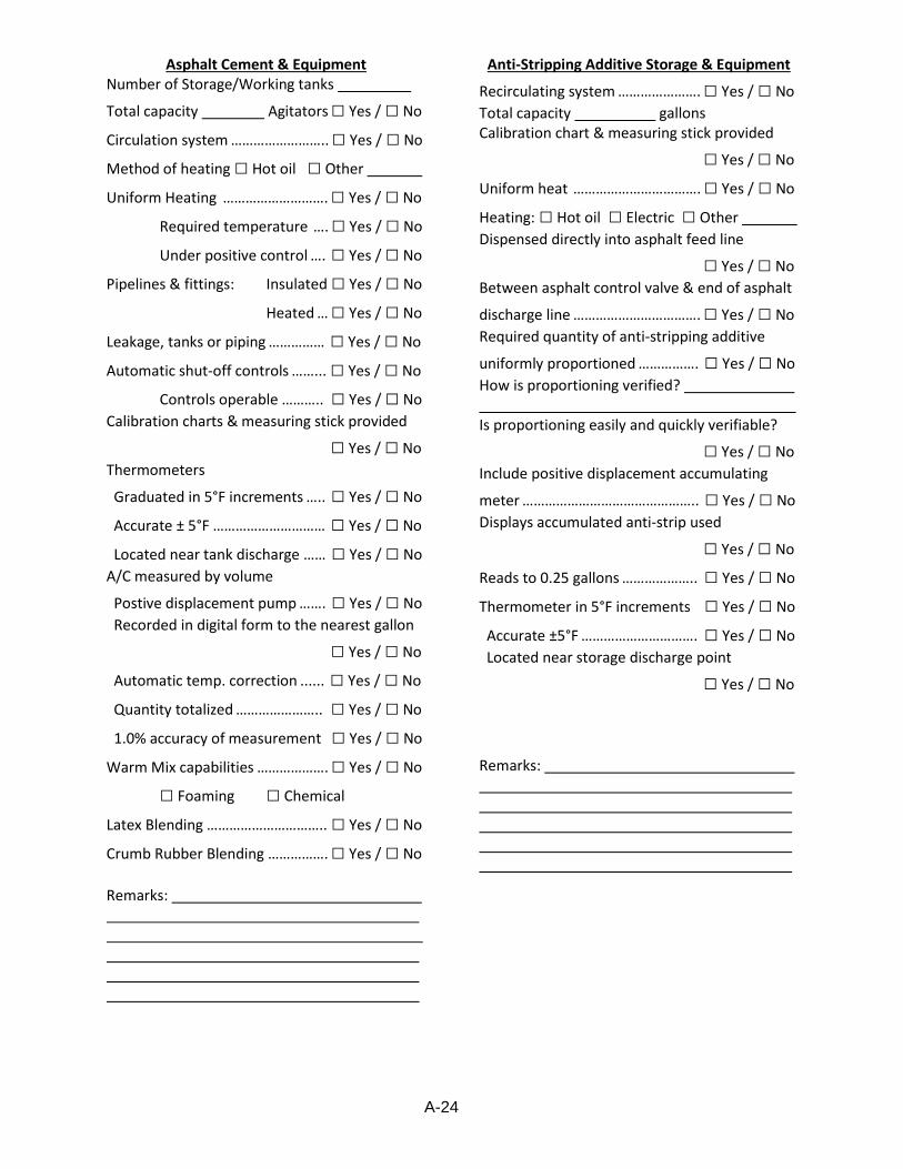
A-24
DOTD 03-22-3075 Rev. 10/15 Page 1 of 8
Asphalt Cement & Equipment Number of Storage/Working tanks
Total capacity Agitators □ Yes / □ No
Circulation system …………………….. □ Yes / □ No
Method of heating □ Hot oil □ Other
Uniform Heating ………………………. □ Yes / □ No
Required temperature …. □ Yes / □ No
Under positive control …. □ Yes / □ No
Pipelines & fittings: Insulated □ Yes / □ No
Heated … □ Yes / □ No
Leakage, tanks or piping …………… □ Yes / □ No
Automatic shut-off controls ……... □ Yes / □ No
Controls operable ……….. □ Yes / □ No
Calibration charts & measuring stick provided
□ Yes / □ No
Thermometers
Graduated in 5°F increments ….. □ Yes / □ No
Accurate ± 5°F ………………………… □ Yes / □ No
Located near tank discharge …… □ Yes / □ No
A/C measured by volume
Postive displacement pump ……. □ Yes / □ No
Recorded in digital form to the nearest gallon
□ Yes / □ No
Automatic temp. correction ...... □ Yes / □ No
Quantity totalized ………………….. □ Yes / □ No
1.0% accuracy of measurement □ Yes / □ No
Warm Mix capabilities ………………. □ Yes / □ No
□ Foaming □ Chemical
Latex Blending ………………………….. □ Yes / □ No
Crumb Rubber Blending ……………. □ Yes / □ No
Remarks:
Anti-Stripping Additive Storage & Equipment
Recirculating system …………………. □ Yes / □ No
Total capacity gallons Calibration chart & measuring stick provided
□ Yes / □ No
Uniform heat ……………………………. □ Yes / □ No
Heating: □ Hot oil □ Electric □ Other
Dispensed directly into asphalt feed line
□ Yes / □ No
Between asphalt control valve & end of asphalt
discharge line ……………………………. □ Yes / □ No
Required quantity of anti-stripping additive
uniformly proportioned ……………. □ Yes / □ No
How is proportioning verified? Is proportioning easily and quickly verifiable?
□ Yes / □ No
Include positive displacement accumulating
meter ……………………………………….. □ Yes / □ No
Displays accumulated anti-strip used
□ Yes / □ No
Reads to 0.25 gallons ……………….. □ Yes / □ No
Thermometer in 5°F increments □ Yes / □ No
Accurate ±5°F …………………………. □ Yes / □ No
Located near storage discharge point
□ Yes / □ No
Remarks:
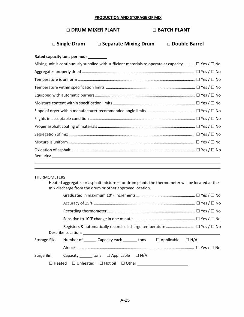
A-25
DOTD 03-22-3075 Rev. 10/15 Page 1 of 8
PRODUCTION AND STORAGE OF MIX
□ DRUM MIXER PLANT □ BATCH PLANT
□ Single Drum □ Separate Mixing Drum □ Double Barrel
Rated capacity tons per hour
Mixing unit is continuously supplied with sufficient materials to operate at capacity ……….. □ Yes / □ No
Aggregates properly dried ………………………………………………………………………………………………… □ Yes / □ No
Temperature is uniform …………………………………………………………………………………………………….. □ Yes / □ No
Temperature within specification limits ……………………………………………………………………………. □ Yes / □ No
Equipped with automatic burners ……………………………………………………………………………………… □ Yes / □ No
Moisture content within specification limits ……………………………………………………………………… □ Yes / □ No
Slope of dryer within manufacturer recommended angle limits ………………………………………… □ Yes / □ No
Flights in acceptable condition ………………………………………………………………………………………….. □ Yes / □ No
Proper asphalt coating of materials …………………………………………………………………………………… □ Yes / □ No
Segregation of mix ………………………………………………………………………………………………………….... □ Yes / □ No
Mixture is uniform ……………………………………………………………………………………………………………. □ Yes / □ No
Oxidation of asphalt ………………………………………………………………………………………………………….. □ Yes / □ No
Remarks: THERMOMETERS
Heated aggregates or asphalt mixture – for drum plants the thermometer will be located at the mix discharge from the drum or other approved location.
Graduated in maximum 10°F increments …………………………………………………. □ Yes / □ No
Accuracy of ±5°F ………………………………………………………………………………………. □ Yes / □ No
Recording thermometer …………………………………………………………………………… □ Yes / □ No
Sensitive to 10°F change in one minute ……………………………………………………. □ Yes / □ No
Registers & automatically records discharge temperature ………………………. □ Yes / □ No
Describe Location:
Storage Silo Number of Capacity each tons □ Applicable □ N/A
Airlock……………………………………………………………………………………………………… □ Yes / □ No
Surge Bin Capacity tons □ Applicable □ N/A
□ Heated □ Unheated □ Hot oil □ Other
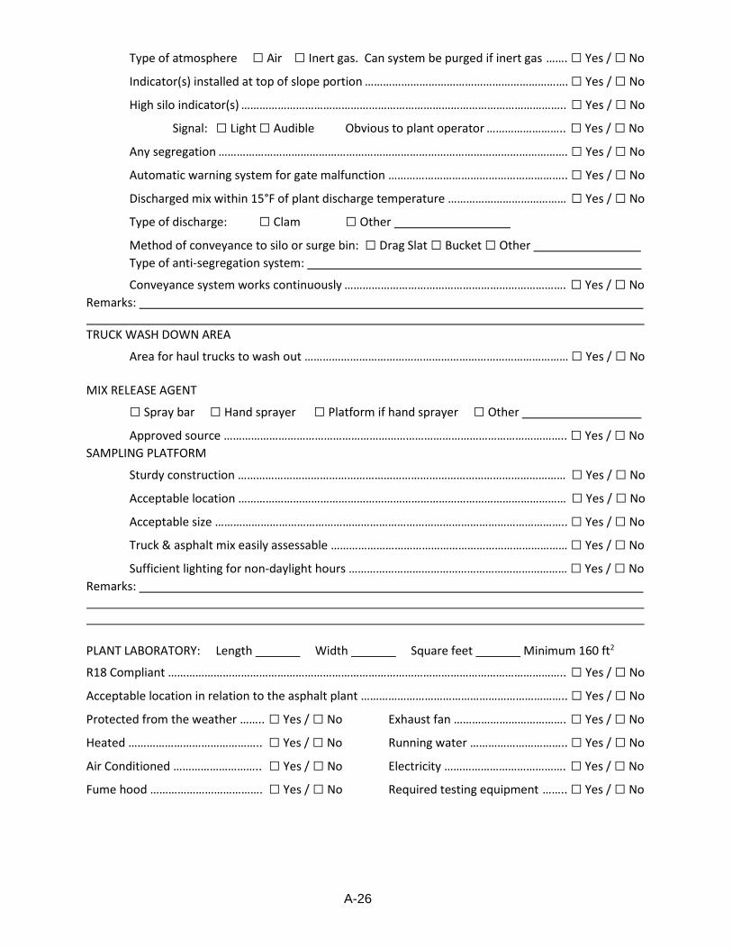
A-26
DOTD 03-22-3075 Rev. 10/15 Page 1 of 8
Type of atmosphere □ Air □ Inert gas. Can system be purged if inert gas ……. □ Yes / □ No
Indicator(s) installed at top of slope portion …………………………………………………………. □ Yes / □ No
High silo indicator(s) …………………………………………………………………………………………….. □ Yes / □ No
Signal: □ Light □ Audible Obvious to plant operator …………………….. □ Yes / □ No
Any segregation ……………………………………………………………………………………………………. □ Yes / □ No
Automatic warning system for gate malfunction ………………………………………………….. □ Yes / □ No
Discharged mix within 15°F of plant discharge temperature ………………………………… □ Yes / □ No
Type of discharge: □ Clam □ Other
Method of conveyance to silo or surge bin: □ Drag Slat □ Bucket □ Other
Type of anti-segregation system:
Conveyance system works continuously ………………………………………………………………. □ Yes / □ No
Remarks: TRUCK WASH DOWN AREA
Area for haul trucks to wash out …………………………………………………………………………… □ Yes / □ No
MIX RELEASE AGENT
□ Spray bar □ Hand sprayer □ Platform if hand sprayer □ Other
Approved source ………………………………………………………………………………………………….. □ Yes / □ No
SAMPLING PLATFORM
Sturdy construction ……………………………………………………………………………………………… □ Yes / □ No
Acceptable location ……………………………………………………………………………………………… □ Yes / □ No
Acceptable size …………………………………………………………………………………………………….. □ Yes / □ No
Truck & asphalt mix easily assessable …………………………………………………………………… □ Yes / □ No
Sufficient lighting for non-daylight hours ……………………………………………………………… □ Yes / □ No
Remarks: PLANT LABORATORY: Length Width Square feet Minimum 160 ft2
R18 Compliant ………………………………………………………………………………………………………………….. □ Yes / □ No
Acceptable location in relation to the asphalt plant ………………………………………………………….. □ Yes / □ No
Protected from the weather …….. □ Yes / □ No
Heated …………………………………….. □ Yes / □ No
Air Conditioned ……………………….. □ Yes / □ No
Fume hood ………………………………. □ Yes / □ No
Exhaust fan ………………………………. □ Yes / □ No
Running water ………………………….. □ Yes / □ No
Electricity …………………………………. □ Yes / □ No
Required testing equipment …….. □ Yes / □ No
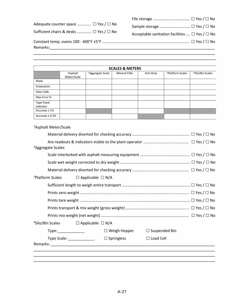
A-27
DOTD 03-22-3075 Rev. 10/15 Page 1 of 8
Adequate counter space ………….. □ Yes / □ No
Sufficient chairs & desks …………… □ Yes / □ No
File storage ………………………………. □ Yes / □ No
Sample storage …………………………. □ Yes / □ No
Acceptable sanitation facilities …. □ Yes / □ No
Constant temp. ovens 100 - 400°F ±5°F ……………………………………………………………………………. □ Yes / □ No
Remarks:
SCALES & METERS
1Asphalt Meter/Scale
2Aggregate Scale Mineral Filler Anti-Strip 3Platform Scales 4Silo/Bin Scales
Make Graduation Date Calib. Max Error % Type Panel Indicator
Accurate ± 1% Accurate ± 0.5%
1Asphalt Meter/Scale
Material delivery diverted for checking accuracy …………………………………………………. □ Yes / □ No
Are readouts & indicators visible to the plant operator ………………………………………. □ Yes / □ No 2Aggregate Scales
Scale interlocked with asphalt measuring equipment ………………………………………….. □ Yes / □ No
Scale wet weight corrected to dry weight …………………………………………………………….. □ Yes / □ No
Material delivery diverted for checking accuracy ………………………………………………… □ Yes / □ No
3Platform Scales □ Applicable □ N/A
Sufficient length to weigh entire transport …………………………………………………………… □ Yes / □ No
Prints zero weight ……………………………………………………………………………………………….. □ Yes / □ No
Prints tare weight …………………………………………………………………………………………………. □ Yes / □ No
Prints transport & mix weight (gross weight) …………………………………………………….... □ Yes / □ No
Prints mix weight (net weight) …………………………………………………………………………….. □ Yes / □ No
4Silo/Bin Scales □ Applicable □ N/A
Type: □ Weigh Hopper □ Suspended Bin
Type Scale: □ Springless □ Load Cell
Remarks:
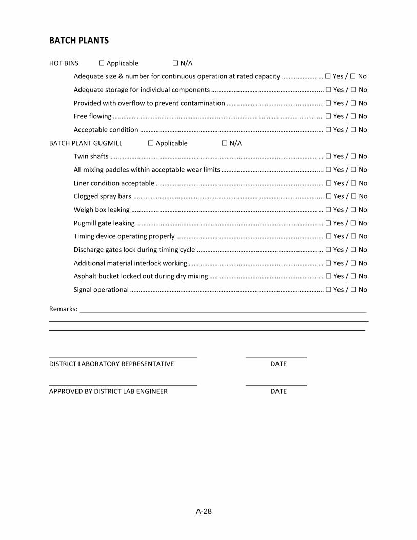
A-28
DOTD 03-22-3075 Rev. 10/15 Page 1 of 8
BATCH PLANTS
HOT BINS □ Applicable □ N/A
Adequate size & number for continuous operation at rated capacity …………………… □ Yes / □ No
Adequate storage for individual components ……………………………………………………….. □ Yes / □ No
Provided with overflow to prevent contamination ……………………………………………….. □ Yes / □ No
Free flowing …………………………………………………………………………………………………………. □ Yes / □ No
Acceptable condition ……………………………………………………………………………………………. □ Yes / □ No
BATCH PLANT GUGMILL □ Applicable □ N/A
Twin shafts …………………………………………………………………………………………………………… □ Yes / □ No
All mixing paddles within acceptable wear limits ………………………………………………….. □ Yes / □ No
Liner condition acceptable ……………………………………………………………………………………. □ Yes / □ No
Clogged spray bars ……………………………………………………………………………………………….. □ Yes / □ No
Weigh box leaking ………………………………………………………………………………………………… □ Yes / □ No
Pugmill gate leaking ……………………………………………………………………………………………… □ Yes / □ No
Timing device operating properly …………………………………………………………………………. □ Yes / □ No
Discharge gates lock during timing cycle ………………………………………………………………. □ Yes / □ No
Additional material interlock working …………………………………………………………………… □ Yes / □ No
Asphalt bucket locked out during dry mixing ………………………………………………………… □ Yes / □ No
Signal operational …………………………………………………………………………………………………. □ Yes / □ No
Remarks: DISTRICT LABORATORY REPRESENTATIVE DATE APPROVED BY DISTRICT LAB ENGINEER DATE

A-29
State of Louisiana
Department of Transportation and Development
Asphalt Concrete Plant Review
Plant: Location:
Company: Arrival Time: Departure:
Date: Inspector/title:
Contractor Technician(s) & Title:
Review to be completed & maintained at the District Laboratory. Maintain separate files for each plant in the district.
Completed minimum once every 90 days
Yes No
Lab AASHTO R18 current O O
Lab Equipment Manual current O O
Scales & Meters calibrations current O O
Stockpiles
Proper drainage O O
Comments/Findings:
Separated with partitions or space between each material O O
Comments/Findings:
Segregation O O
Comments/Findings:
Does contractor fractionate RAP O O
Stockpiled separately O O
Does contractor use 1 inch screen for RAP O O
Comments/Findings:
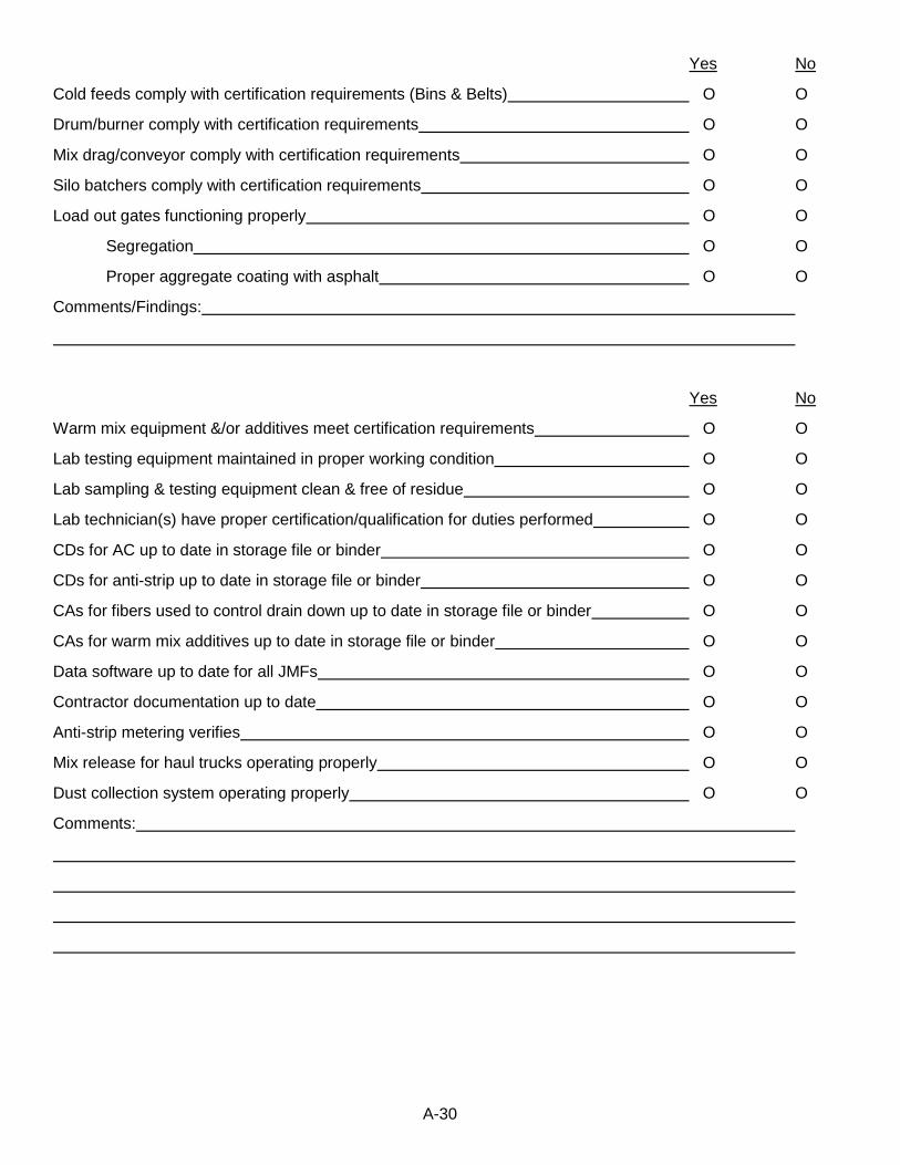
A-30
Yes No
Cold feeds comply with certification requirements (Bins & Belts) O O
Drum/burner comply with certification requirements O O
Mix drag/conveyor comply with certification requirements O O
Silo batchers comply with certification requirements O O
Load out gates functioning properly O O
Segregation O O
Proper aggregate coating with asphalt O O
Comments/Findings:
Yes No
Warm mix equipment &/or additives meet certification requirements O O
Lab testing equipment maintained in proper working condition O O
Lab sampling & testing equipment clean & free of residue O O
Lab technician(s) have proper certification/qualification for duties performed O O
CDs for AC up to date in storage file or binder O O
CDs for anti-strip up to date in storage file or binder O O
CAs for fibers used to control drain down up to date in storage file or binder O O
CAs for warm mix additives up to date in storage file or binder O O
Data software up to date for all JMFs O O
Contractor documentation up to date O O
Anti-strip metering verifies O O
Mix release for haul trucks operating properly O O
Dust collection system operating properly O O
Comments:
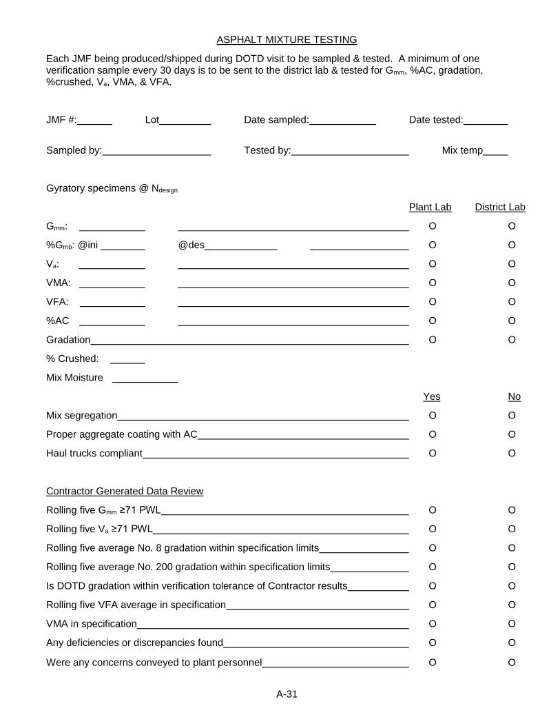
A-31
ASPHALT MIXTURE TESTING
Each JMF being produced/shipped during DOTD visit to be sampled & tested. A minimum of one verification sample every 30 days is to be sent to the district lab & tested for Gmm, %AC, gradation, %crushed, Va, VMA, & VFA.
JMF #: Lot Date sampled: Date tested:
Sampled by: Tested by: Mix temp
Gyratory specimens @ Ndesign
Plant Lab District Lab
Gmm: O O
%Gmb: @ini @des O O
Va: O O
VMA: O O
VFA: O O
%AC O O
Gradation O O
% Crushed:
Mix Moisture
Yes No
Mix segregation O O
Proper aggregate coating with AC O O
Haul trucks compliant O O
Contractor Generated Data Review
Rolling five Gmm ≥71 PWL O O
Rolling five Va ≥71 PWL O O
Rolling five average No. 8 gradation within specification limits O O
Rolling five average No. 200 gradation within specification limits O O
Is DOTD gradation within verification tolerance of Contractor results O O
Rolling five VFA average in specification O O
VMA in specification O O
Any deficiencies or discrepancies found O O
Were any concerns conveyed to plant personnel O O
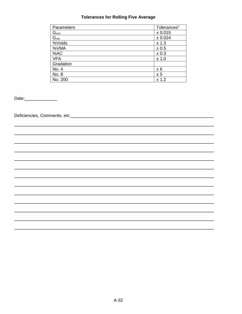
A-32
Tolerances for Rolling Five Average
Parameters Tolerances1
Gmm ± 0.015
Gmb ± 0.024
%Voids ± 1.3
%VMA ± 0.5
%AC ± 0.3
VFA ± 1.0
Gradation
No. 4 ± 6
No. 8 ± 5
No. 200 ± 1.2
Date:
Deficiencies, Comments, etc:

A-33
ASPHALT CEMENT SAMPLES
Working tank AC samples for each PG grade on site at time of visit. To be tested at the District Lab or Materials Lab. Transport samples taken at the request of the Materials Lab
Inspector:
Date Sampled Supplier Working Tank Transport
PG 58-28 O O
PG 67-22 O O
PG 70-22 O O
PG 76-22 O O
PG 82-22 O O
Yes No
AC tanks & heaters meet certification requirements O O
AC metering verifies O O
Comments:
Inspector: Date:
DLE: Date:
CDs from previous month attached. Date: initials:
Deficiencies Corrected. Date: initials: Comments:

A-34

A-35
Asphalt Concrete Roadway Equipment Review
State of Louisiana
Department of Transportation and Development
CONTRACTOR ASPHALT CONCRETE ROADWAY EQUIPMENT REVIEW
Date: Project No.: District: Gang:
Inspector:
Review of equipment used for Asphalt Concrete cold planning and paving. To be included in project 2059.
Asphalt Milling Machine
Make & Model:
Yes No
Sufficient power, traction, & stability to provide uniform profile grade & cross slope O O
Capable of controlling uniform profile grade & cross slope from an erected string line,
shoe device or approved traveling reference plane O O
Does method of control accurately reflect the average grade of the surface to be operated on O O
Automatic system for controlling cross slope O O
Milling drum true to round O O
Milling teeth in sufficient number & proper condition to produce a uniform surface & texture O O
Fuel or fluid leak O O
Asphalt Distributor
Make & Model:
Serial No.:
ASTM D 2995 Calibrated O O
Date Calibrated: Calibration Current O O
Copy of Calibration O O
Overall condition acceptable O O
Fluid or fuel leaks O O
Heating system capable of heating material to proper temperature & maintaining temperature O O
Thermometer easily readable O O
Acceptable accuracy O O
Location:
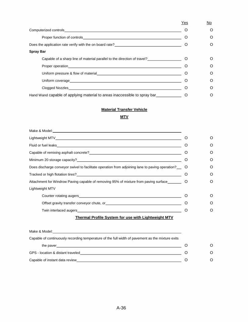
A-36
Yes No
Computerized controls O O
Proper function of controls O O
Does the application rate verify with the on board rate? O O
Spray Bar
Capable of a sharp line of material parallel to the direction of travel? O O
Proper operation O O
Uniform pressure & flow of material O O
Uniform coverage O O
Clogged Nozzles O O
Hand Wand capable of applying material to areas inaccessible to spray bar O O
Material Transfer Vehicle
MTV
Make & Model:
Lightweight MTV O O
Fluid or fuel leaks O O
Capable of remixing asphalt concrete? O O
Minimum 20 storage capacity? O O
Does discharge conveyor swivel to facilitate operation from adjoining lane to paving operation? O O
Tracked or high flotation tires? O O
Attachment for Windrow Paving capable of removing 95% of mixture from paving surface O O
Lightweight MTV
Counter rotating augers O O
Offset gravity transfer conveyor chute, or O O
Twin interlaced augers O O
Thermal Profile System for use with Lightweight MTV
Make & Model:
Capable of continuously recording temperature of the full width of pavement as the mixture exits
the paver O O
GPS - location & distant traveled O O
Capable of instant data review O O
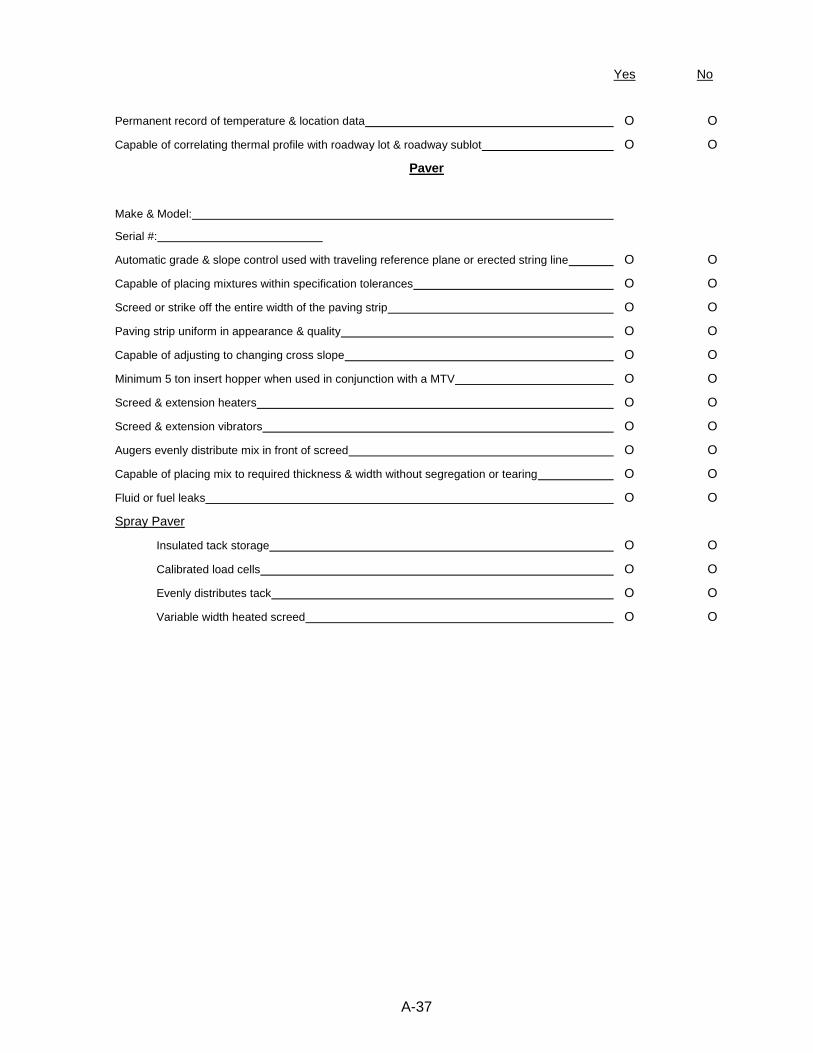
A-37
Page 1 of 1
Yes No
Permanent record of temperature & location data O O
Capable of correlating thermal profile with roadway lot & roadway sublot O O
Paver
Make & Model:
Serial #:
Automatic grade & slope control used with traveling reference plane or erected string line O O
Capable of placing mixtures within specification tolerances O O
Screed or strike off the entire width of the paving strip O O
Paving strip uniform in appearance & quality O O
Capable of adjusting to changing cross slope O O
Minimum 5 ton insert hopper when used in conjunction with a MTV O O
Screed & extension heaters O O
Screed & extension vibrators O O
Augers evenly distribute mix in front of screed O O
Capable of placing mix to required thickness & width without segregation or tearing O O
Fluid or fuel leaks O O
Spray Paver
Insulated tack storage O O
Calibrated load cells O O
Evenly distributes tack O O
Variable width heated screed O O
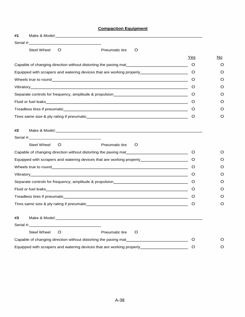
A-38
Page 1 of 1
Compaction Equipment
#1 Make & Model:
Serial #:
Steel Wheel O Pneumatic tire O
Yes No
Capable of changing direction without distorting the paving mat O O
Equipped with scrapers and watering devices that are working properly O O
Wheels true to round O O
Vibratory O O
Separate controls for frequency, amplitude & propulsion O O
Fluid or fuel leaks O O
Treadless tires if pneumatic O O
Tires same size & ply rating if pneumatic O O
#2 Make & Model:
Serial #:
Steel Wheel O Pneumatic tire O
Capable of changing direction without distorting the paving mat O O
Equipped with scrapers and watering devices that are working properly O O
Wheels true to round O O
Vibratory O O
Separate controls for frequency, amplitude & propulsion O O
Fluid or fuel leaks O O
Treadless tires if pneumatic O O
Tires same size & ply rating if pneumatic O O
#3 Make & Model:
Serial #:
Steel Wheel O Pneumatic tire O
Capable of changing direction without distorting the paving mat O O
Equipped with scrapers and watering devices that are working properly O O
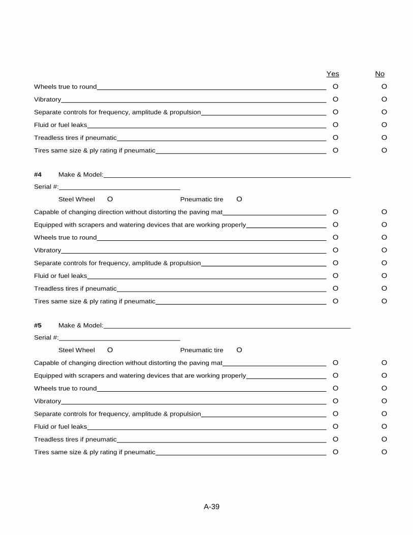
A-39
Yes No
Wheels true to round O O
Vibratory O O
Separate controls for frequency, amplitude & propulsion O O
Fluid or fuel leaks O O
Treadless tires if pneumatic O O
Tires same size & ply rating if pneumatic O O
#4 Make & Model:
Serial #:
Steel Wheel O Pneumatic tire O
Capable of changing direction without distorting the paving mat O O
Equipped with scrapers and watering devices that are working properly O O
Wheels true to round O O
Vibratory O O
Separate controls for frequency, amplitude & propulsion O O
Fluid or fuel leaks O O
Treadless tires if pneumatic O O
Tires same size & ply rating if pneumatic O O
#5 Make & Model:
Serial #:
Steel Wheel O Pneumatic tire O
Capable of changing direction without distorting the paving mat O O
Equipped with scrapers and watering devices that are working properly O O
Wheels true to round O O
Vibratory O O
Separate controls for frequency, amplitude & propulsion O O
Fluid or fuel leaks O O
Treadless tires if pneumatic O O
Tires same size & ply rating if pneumatic O O

A-40
Page 1 of 1 #6 Make & Model:
Serial #:
Steel Wheel O Pneumatic tire O
Yes No
Capable of changing direction without distorting the paving mat O O
Equipped with scrapers and watering devices that are working properly O O
Wheels true to round O O
Vibratory O O
Separate controls for frequency, amplitude & propulsion O O
Fluid or fuel leaks O O
Treadless tires if pneumatic O O
Tires same size & ply rating if pneumatic O O
Comments:
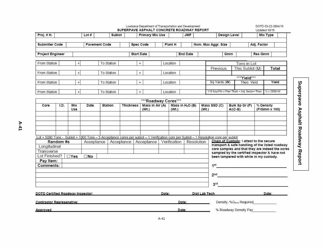
A-41
S
up
erp
ave
As
ph
alt R
oa
dw
ay R
ep
ort
A-4
1
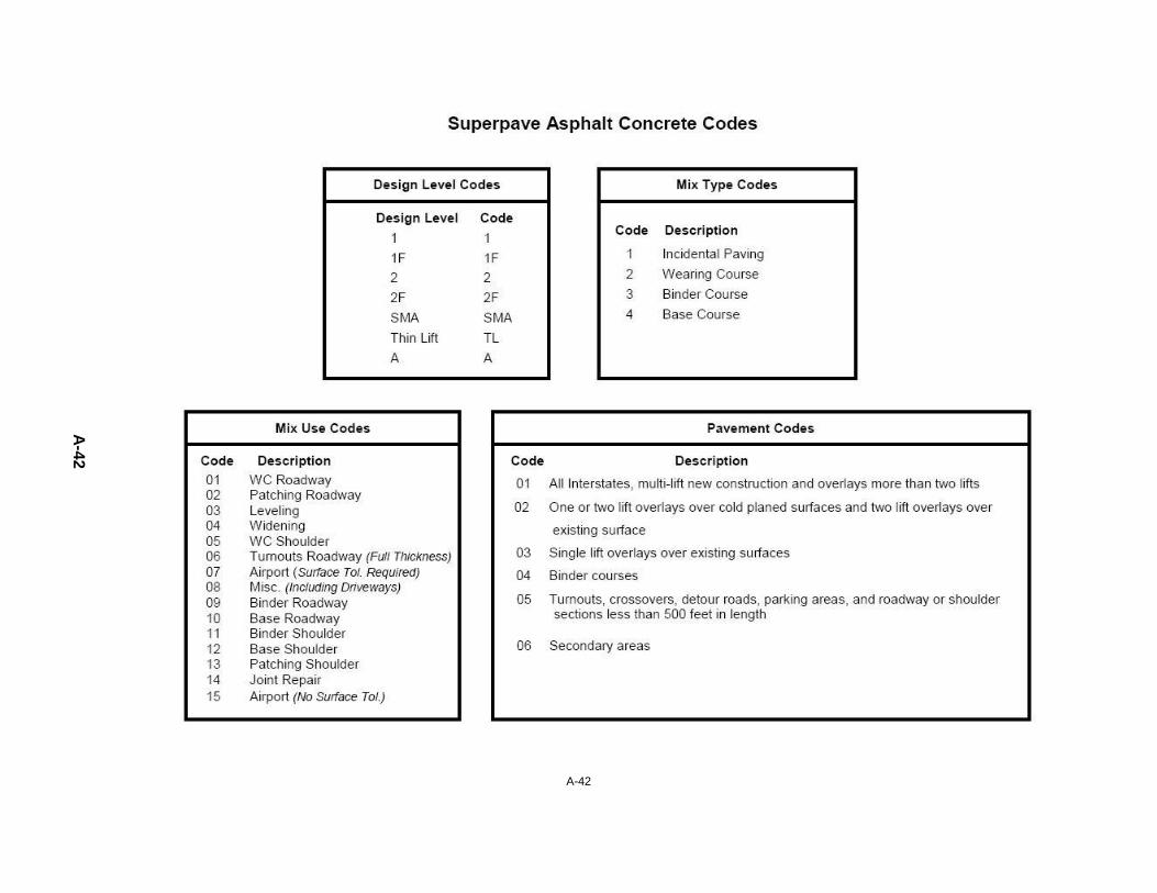
A-42
A-4
2

A-43
Suggested Tie-In Procedure
Although suggested, this procedure is not required. Smoothness results in defining the rate of elevation change at the approach. Here is the process for final surface elevation:
1. Start with a string line attached to the approach slab or bridge end (or use rod readings.) Use the string to project the slope until the pavement is touched (there may be occasions when the string does not touch pavement)
2. Attach a second string line to the approach slab (or use rod readings) to find the
suggested elevation change using the ratio: 1” rise : (1 linear foot x speed limit). Again, projecting the slope until the pavement is touched
For example:
If the speed limit is 60 mph, the suggested elevation change should be 1” per 60 linear feet.
3. If the speed limit is 70 mph, the maximum change in elevation is 1 inch per 70 feet. 4. Select the shorter of items 1 or 2 (above) for the tie-in point.
5. Measure the distance under the string line from the bridge end (0”) to the tie-in
point (0”) and mark the pavement for the required fill depth at 5 or 10 ft. intervals. This will be the fill thickness (or in some cases a cut) to get to final surface elevation.
6. Draw plan and profile views with the information then submit them to the PE for
review with the estimated asphalt quantity for leveling. If there is a drastic elevation difference, the 1” per 70 ft. for 70 mph can be modified as necessary, but no greater than 2” per 70 ft. @ 70 mph. Note: String line per 502.08.2.2, for initial data and layout (10 ft. of string on the bridge and as long as needed off the bridge), and String line per 502.07, for final wearing surface 10 ft. and 40 ft. with a straight edge.

A-44

A-45
Weight Certification Tag (example)

A-46