Embed Size (px)
Citation preview
Phillip Dowson is General Manager,Materials Engineering, with The ElliottGroup, in Jeannette, Pennsylvania. He has38 years of experience in the turbomachineryindustry. Mr. Dowson is responsible forthe metallurgical and welding engineeringfor the various Elliott product lines withinthe company. He is the author/coauthorof a number of technical articles, relatedto topics such as abradable seals, high
temperature corrosion, fracture mechanics, and welding/brazing ofimpellers, and has been awarded numerous patents.Mr. Dowson graduated from Newcastle Polytechnic in
Metallurgy and did his postgraduate work (M.S. degree) in WeldingEngineering. He is a member of ASM, NACE, ASTM, and TWI.
David Dowson is a Service Engineer(Repairs) with the Elliott Group, inJeannette, Pennsylvania. He has beeninvolved with material related failureanalysis, repairs to rotating and nonrotatingequipment, and aftermarket support.Mr. Dowson received his B.S. degree
(2003) from the University of Pittsburgh.
ABSTRACT
In today’s marketplace the repairs of various componentsespecially long lead items for turbomachinery equipment are animportant factor for the maintaining reliability and performance ofthe equipment. This paper will describe repairs applied to compressorsand steam turbines.Various types of repairs will be discussed and how they are
applied to rotors, stationary components such as diaphragms andcasings. The repairs will be applied to various scenarios that thecomponents have been subjected to. The areas covered will be:
• Mechanical damage caused by rub of rotor on shaft/diaphragm.• Foreign object damage.• Erosion caused by either solid particle or liquid.• Fretting damage.• Fatigue.• Creep.• Corrosion.
Also a review and understanding of the damage mechanisms andwhat analysis and/or nondestructive testing (NDT) method can beapplied to quantify the damage and maintain the reliability of therepair. Various methods will be discussed to assess the damagemechanisms and how to evaluate the extent of the damage so onecan assess whether a repair is necessary or the component canfunction as an as-in condition. Types of repair methods that willbe discussed are weld repairs, application of sprayed coating,mechanical fixes, electroless/electrolytic type coating and metalstitching type fixes. The repair methods applied are design processprocedures utilizing a design for fitness for service approach.
INTRODUCTION
In today’s marketplace the repairs of various componentsespecially long lead components for turbomachinery equipmentare an important factor for maintaining reliability and performanceof the equipment. Over the years original equipment manufacturers(OEMs) have developed proven repair procedures for applicationto these long lead items such as casings, shafts, diaphragms,blades, impellers, etc. Most OEMs are continuously developingand reviewing new ways to repair components to reduce costsand/or delivery time in order to remain competitive. Sincedowntime of rotating equipment can be costly to the end user,OEMs have developed design proven repair procedures utilizing adesign fitness for service approach. This paper will describe repairs applied to centrifugal compressors
and steam turbines. The repairs of components that will bediscussed will be rotors, stationary components such asdiaphragms and casings. For repairing these components, one mustunderstand the cause of the failure and consequently apply a repairprocedure that will address the failed scenario. The various failedscenarios that will be covered are:
• Mechanical damage caused by rub of rotor on shaft/diaphragm.• Foreign object damage.• Erosion caused by either solid particle or liquid.• Fretting damage.• Fatigue.• Creep.• Corrosion.CENTRIFUGAL COMPRESSORS
Casings
Generally repairs to compressor casings are mainly due toissues related to erosion/corrosion or mechanical damage. In somecases especially with 30+ year old units that are cast compressorcomponents inherent defects such as shrinkage can propagate with
79
APPLICATION OF REPAIRS TO TURBOMACHINERY EQUIPMENTIN OIL REFINERY, CHEMICAL, AND POWER GENERATION PLANTS
byPhillip Dowson
General Manager Materials Engineering
andDavid Dowson
Service Engineer (Repairs)
The Elliott Group
Jeannette, Pennsylvania
time to the surface. These defects have to be evaluated and ifnecessary repaired to a tolerant defect size. This analysis isperformed by utilizing fracture mechanics.The materials for compressor casings have not changed over the
past 30 years. The specifications of OEM have refined thechemistry to obtain cleaner materials, improvement in toughnessand improvement in reducing the embrittlement effect. Table 1shows the specifications for compressor casings.
Table 1. Shows the Specifications for Compressor Casings.
All OEMs perform repairs to casings utilizing weldingprocedure specifications that have been qualified. In most casesthe weld repairs are performed without a post weld heat treatmentto maintain dimensional tolerances. If a post weld heat treatment isneeded generally both halves of the casing are bolted togetherwith dummy diaphragms placed inside and dummy end plates tominimize axial movement. This type of heat treatment procedure hasbeen performed to correct a compressor casing defect and has beenable to obtain satisfactory dimensional acceptance. Over the past 10years other techniques have been developed by OEMs to addressrepairs utilizing welding and not performing a post weld heattreatment. One of the techniques is called temper bead technique.Temper bead welding refers to a specific welding approach in
which the heat of deposited weld layers is controlled so thatsufficient heat is produced to temper each previously depositedweld layer. Welding heat is directed to the heat-affected zone (HAZ)and will produce requisite strength and toughness propertieswithout the need for any high temperature post weld heattreatment. The approach employs two or more weld layers appliedconsecutively to generate both weld and HAZ properties that areequal or superior to the base metal. The technique is applicable toa variety of carbon and low alloy steel materials. In addition temperbead repairs are permitted using gas tungsten arc welding (GTAW)methods. The shielded metal arc welding (SMAW) methodminimizes the depth of the base material HAZ by applying small3/32 inch diameter electrodes for the initial layer. The next layeris applied with � inch diameter electrodes and the third andsucceeding layer are applied using � inch and 5/32 inch diameterelectrodes. Different companies may vary the sequential patternbut the overall intent is to minimize penetration of the initial layerand follow with a layer deposited using a larger diameter electrodeso that a higher heat input would be generated. This sequenceprovides the heat necessary for tempering brittle transformationproducts in the weld HAZ. The HAZ toughness produced will beequal or superior to the substrate material because the cooling rateof the base material at the fusion line is much faster than theoriginal cooling rate of the base material. This produces a superiormicrostructure that upon tempering exhibits toughness that istypically superior to the original base material. A key componentto evaluate for carbon and low alloy steels temper bead applicationis the HAZ hardness. However although hardness is examined it is
considered less important in non H2S environments becausean acceptable toughness implies a defined capacity to sustaindeformation in a cracked body without crack extension. Datashown in Table 2 for carbon and low alloy steels demonstrates thebeneficial results obtained.
Table 2. Tabulation of Test Data Used in the HAZ Toughness Evaluation.
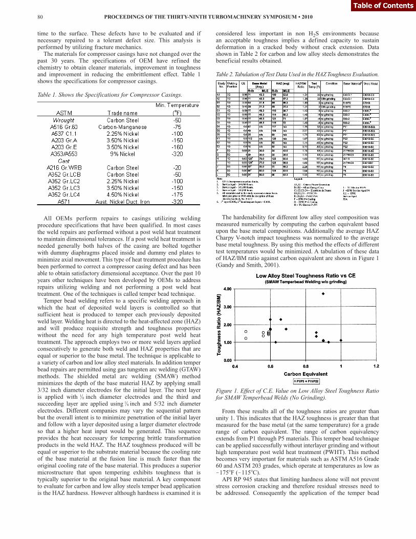
The hardenability for different low alloy steel composition wasmeasured numerically by computing the carbon equivalent basedupon the base metal compositions. Additionally the average HAZCharpy V-notch impact toughness was normalized to the averagebase metal toughness. By using this method the effects of differenttest temperatures would be minimized. A tabulation of these dataof HAZ/BM ratio against carbon equivalent are shown in Figure 1(Gandy and Smith, 2001).
Figure 1. Effect of C.E. Value on Low Alloy Steel Toughness Ratiofor SMAW Temperbead Welds (No Grinding).
From these results all of the toughness ratios are greater thanunity 1. This indicates that the HAZ toughness is greater than thatmeasured for the base metal (at the same temperature) for a graderange of carbon equivalent. The range of carbon equivalencyextends from P1 through P5 materials. This temper bead techniquecan be applied successfully without interlayer grinding and withouthigh temperature post weld heat treatment (PWHT). This methodbecomes very important for materials such as ASTM A516 Grade60 and ASTM 203 grades, which operate at temperatures as low as!175�F (!115�C).API RP 945 states that limiting hardness alone will not prevent
stress corrosion cracking and therefore residual stresses need tobe addressed. Consequently the application of the temper bead
PROCEEDINGS OF THE THIRTY-NINTH TURBOMACHINERY SYMPOSIUM • 201080
1/81/8
technique becomes an alternative acceptable approach to hightemperature PWHT. (Refer to ASME code rules for the applicationof temper bead welding, RRAC code development activities, EPRICharlotte, NC 2003 1002943.)Although carbon and low alloy steels have had approved weld
repair procedures by all OEMs, successful qualified repair proceduresof nodular or flake graphite cast iron is not as straightforwardcompared to steel. Minor weld repairs have been done successfully bySMAW using nickel and nickel-iron electrodes. Nodular cast ironespecially the ferritic grades have more ductility as compared to castiron and therefore can take the contraction and hardening during thewelding process. For flake cast iron there is no give and therefore thecontraction and hardenability can lead to cracking. The authors’company has procedures for welding both nodular and cast iron withpreheats below 800�F (427�C). Other welding methods for cast ironare with preheats greater than 1300�F (704�C) for fusion weldingusing a cast iron filler rod using oxyacetylene welding.Another technique is called metal stitching. This process has
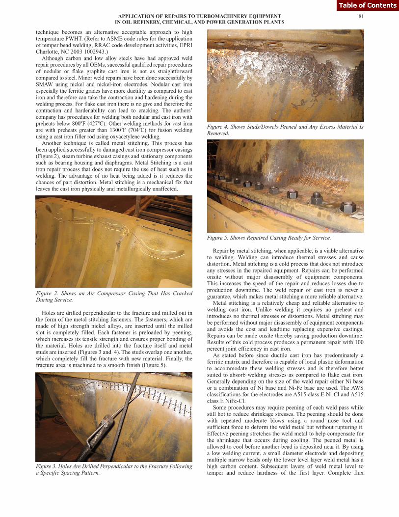
been applied successfully to damaged cast iron compressor casings(Figure 2), steam turbine exhaust casings and stationary componentssuch as bearing housing and diaphragms. Metal Stitching is a castiron repair process that does not require the use of heat such as inwelding. The advantage of no heat being added is it reduces thechances of part distortion. Metal stitching is a mechanical fix thatleaves the cast iron physically and metallurgically unaffected.
Figure 2. Shows an Air Compressor Casing That Has CrackedDuring Service.
Holes are drilled perpendicular to the fracture and milled out inthe form of the metal stitching fasteners. The fasteners, which aremade of high strength nickel alloys, are inserted until the milledslot is completely filled. Each fastener is preloaded by peening,which increases its tensile strength and ensures proper bonding ofthe material. Holes are drilled into the fracture itself and metalstuds are inserted (Figures 3 and 4). The studs overlap one another,which completely fill the fracture with new material. Finally, thefracture area is machined to a smooth finish (Figure 5).
Figure 3. Holes Are Drilled Perpendicular to the Fracture Followinga Specific Spacing Pattern.
Figure 4. Shows Studs/Dowels Peened and Any Excess Material IsRemoved.
Figure 5. Shows Repaired Casing Ready for Service.
Repair by metal stitching, when applicable, is a viable alternativeto welding. Welding can introduce thermal stresses and causedistortion. Metal stitching is a cold process that does not introduceany stresses in the repaired equipment. Repairs can be performedonsite without major disassembly of equipment components.This increases the speed of the repair and reduces losses due toproduction downtime. The weld repair of cast iron is never aguarantee, which makes metal stitching a more reliable alternative.Metal stitching is a relatively cheap and reliable alternative to
welding cast iron. Unlike welding it requires no preheat andintroduces no thermal stresses or distortions. Metal stitching maybe performed without major disassembly of equipment componentsand avoids the cost and leadtime replacing expensive castings.Repairs can be made onsite thereby saving production downtime.Results of this cold process produces a permanent repair with 100percent joint efficiency in cast iron. As stated before since ductile cast iron has predominately a
ferritic matrix and therefore is capable of local plastic deformationto accommodate these welding stresses and is therefore bettersuited to absorb welding stresses as compared to flake cast iron.Generally depending on the size of the weld repair either Ni baseor a combination of Ni base and Ni-Fe base are used. The AWSclassifications for the electrodes are A515 class E Ni-Cl and A515class E NiFe-Cl. Some procedures may require peening of each weld pass while
still hot to reduce shrinkage stresses. The peening should be donewith repeated moderate blows using a round nose tool andsufficient force to deform the weld metal but without rupturing it.Effective peening stretches the weld metal to help compensate forthe shrinkage that occurs during cooling. The peened metal isallowed to cool before another bead is deposited near it. By usinga low welding current, a small diameter electrode and depositingmultiple narrow beads only the lower level layer weld metal has ahigh carbon content. Subsequent layers of weld metal level totemper and reduce hardness of the first layer. Complete flux
81APPLICATION OF REPAIRS TO TURBOMACHINERY EQUIPMENTIN OIL REFINERY, CHEMICAL, AND POWER GENERATION PLANTS
removal is essential after each weld pass before depositing furtherweld metal since entrapped slag can impair the strength propertiesof the weld. Preheat may be applied to prevent cold cracking,reduce hardness in the HAZ, reduce residual stresses and reducedistortion. Satisfactory repair processes have been developed forboth with and without preheat.
COMPRESSOR SHAFTS
Throughout the last 20 years hundreds of shafts have beensuccessfully weld repaired by the authors’ company and to date areoperating as designed. This success rate can be attributed to theanalytical approach that has been developed over the years toassume that the weld repair will function as good as or better thanthe original configuration. This approach was required intensivelyto satisfy a defect tolerant design concept and safety considerations.Also it was necessary to overcome the initial reluctance of theequipment owners and their insurers, who have now embraced thistechnique as a way of reducing financial and technical exposurewhen there is a rotor malfunction. Fundamental to any repair is in knowing the cause of failure
before establishing repair procedures to ensure it does not reoccur.In general all OEMs have processes and standard restorationspecifications that act as guides to assure all initial areas areaddressed prior to the actual repair being initiated. Some of thetools utilized to determine the root cause of the failure and thecondition of the base metal include nondestructive testing,metallurgical failure analysis, mechanical property testing, chemistryanalysis, stress analysis using finite element methodology, frequencyand model testing, fracture mechanics methodology and othertools as needed.
Mechanical Inspection
This is required to check if distortion or bowing has occurred thatwould render the shaft unrepairable or would need to be thermallystraightened. This inspection is done with the following test:
• Dimensional• Concentricity/Runout• Check balance• Nondestructive testing (NDT) to evaluate all rotor surfaces forcracking and other defects
• Visual examination to evaluate condition of shaft surfacesespecially under areas that have contact to impellers, sleeves, thrustcollar, etc. Evidence of fretting in these areas would be a concernand depending on the extent would need to be evaluated for rootcause. Where fretting is slight, these areas may be acceptable as is.Other areas where damage to surface is unacceptable will have tobe removed and either repaired by nickel/electrolytic type coatingor by welding. If a harder surface contact material is required acombination of both can be used.
Generally shafts are manufactured from either rolled bars orforgings and the materials are either AISI 4340 or 4330. Thesematerials can be heat treated to give the required mechanicalproperties such as strength and toughness down to !150�F (!101�C).Repairs to these shafts are generally done by welding using highstrength weld deposits or for repair to shaft journal area using highvelocity oxygen fuel (HVOF) thermal spray processes. The coatingsutilized are either a tungsten carbide coating or chromium carbide.For repairs by welding either GTAW or submerged arc welding
can be utilized using high strength weld deposits. OEMs haveproven repair procedures where they have developed metallurgicaland mechanical data utilizing mock ups that are welded usingOEM’s propriety procedures such as fatigue data, stress corrosioncracking (SCC) data and toughness strength. In determining therequired weld initial strength and toughness the OEMs may have to
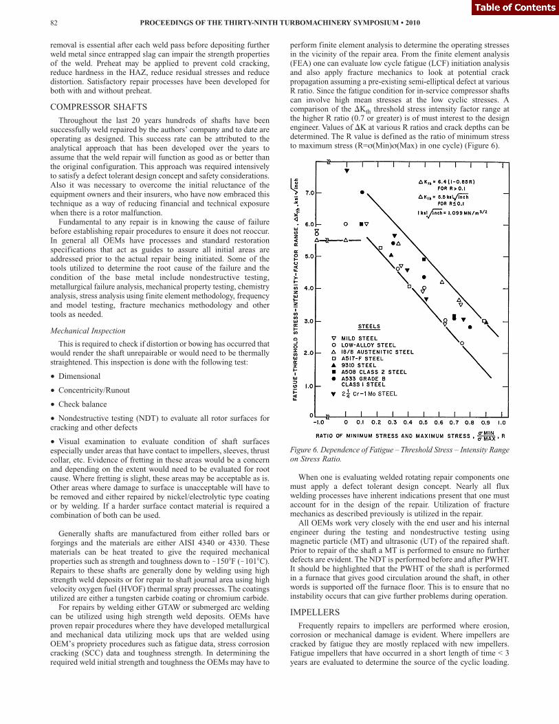
perform finite element analysis to determine the operating stressesin the vicinity of the repair area. From the finite element analysis(FEA) one can evaluate low cycle fatigue (LCF) initiation analysisand also apply fracture mechanics to look at potential crackpropagation assuming a pre-existing semi-elliptical defect at variousR ratio. Since the fatigue condition for in-service compressor shaftscan involve high mean stresses at the low cyclic stresses. Acomparison of the �Kth threshold stress intensity factor range atthe higher R ratio (0.7 or greater) is of must interest to the designengineer. Values of �K at various R ratios and crack depths can bedetermined. The R value is defined as the ratio of minimum stressto maximum stress (R=s(Min)s(Max) in one cycle) (Figure 6).
Figure 6. Dependence of Fatigue – Threshold Stress – Intensity Rangeon Stress Ratio.
When one is evaluating welded rotating repair components onemust apply a defect tolerant design concept. Nearly all fluxwelding processes have inherent indications present that one mustaccount for in the design of the repair. Utilization of fracturemechanics as described previously is utilized in the repair. All OEMs work very closely with the end user and his internal
engineer during the testing and nondestructive testing usingmagnetic particle (MT) and ultrasonic (UT) of the repaired shaft.Prior to repair of the shaft a MT is performed to ensure no furtherdefects are evident. The NDT is performed before and after PWHT.It should be highlighted that the PWHT of the shaft is performedin a furnace that gives good circulation around the shaft, in otherwords is supported off the furnace floor. This is to ensure that noinstability occurs that can give further problems during operation.
IMPELLERS
Frequently repairs to impellers are performed where erosion,corrosion or mechanical damage is evident. Where impellers arecracked by fatigue they are mostly replaced with new impellers.Fatigue impellers that have occurred in a short length of time < 3years are evaluated to determine the source of the cyclic loading.
PROCEEDINGS OF THE THIRTY-NINTH TURBOMACHINERY SYMPOSIUM • 201082
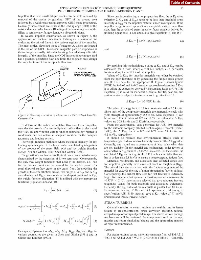
Impellers that have small fatigue cracks can be weld repaired byremoval of the cracks by grinding. NDT of the ground areafollowed by a weld repair using approved OEM tested procedures.Generally these cracks are either at the leading edge (inlet) or theoutside diameter (discharge). Blending of the remaining toes of thefillets to remove any fatigue damage is frequently done. In welded impeller construction, as shown in Figure 7, the
application of fracture mechanics techniques is essential forevaluating the critical flaws in the various regions of the impeller.The most critical flaws are those of category A, which are locatedat the toe of the fillet. Fluorescent magnetic particle inspection isthe technique normally utilized in locating flaws that may affect theintegrity of the impeller. Since the NDT inspection technique usedhas a practical detectable flaw size limit, the engineer must designthe impeller to meet this acceptable flaw size.
Figure 7. Showing Location of Flaws in a Fillet Welded ImpellerConstruction.
To determine the critical acceptable flaw size for an impeller,consider the growth of a semi-elliptical surface flaw at the toe ofthe fillet. By applying the weight function methodology related toweldments, one can obtain an adequate solution for the complexgeometry and loading system.The weight function method is where the stress intensity for any
loading system applied to the body can be calculated by integrationof the product of the stress field s(x) and the weight functionm(x,a) (Niu and Glinka, 1989; Shen and Glinka, 1991).The growth of a surface semi-elliptical crack can be satisfactorily
characterized by the extension of it two semi-axes. Consequently,the only two weight functions that need to be derived, i.e., onefor the deepest point and the second for the surface point of asemi-elliptical surface crack in the crack front. In modeling thegrowth of the semi-elliptical cracks, two ranges of � KIA and � KIBare calculated (� KIA corresponds to the deepest point and � KIB,the weight function (Equation (1)) is utilized with the appropriatefunctions (Equations (2) and (3)).
and
Examples of parameters M1A, M2A, M3A, M1B, M2B, and M3B forvarious geometries are given in Shen and Glinka (1991) and inGlinka and Lambert (1993).
Since one is considering a nonpropagating flaw, the � KI value(whether � KIA and � KIB) needs to be less than threshold stressintensity � KTH for the impeller material under investigation. If theimpeller design is based upon a 3 mm acceptable surface linear flawsize, then the associated stress intensity factor range is derived byutilizing Equations (1), (2), and (3) to give Equations (4) and (5):
and
By applying this methodology, a value � KIA and � KIB can becalculated for a flaw, where a = 0.125 inches, at a particularlocation along the weld toe of the impeller.Values of � KTH for impeller materials can either be obtained
from the open literature or by generating the fatigue crack growthrate (FCGR) data for the appropriate R. Figure 3 shows typicalFCGR for R=0.65 and R=0.2. Another approach to determine �KTHis to utilize the expression derived by Barsom and Rolfe (1977). ThisEquation (6) is valid for martensitic, banitic, ferritic, pearlitic, andaustenitic steels subjected to stress ratios R, greater than 0.1.
The value of � KTH for R < 0.1 is a constant equal to 5.5 ksi√in.Since most of the compressor materials are martensitic steels withyield strength of approximately 552 to 689 MPa, Equation (6) canbe utilized. For R ratios of 0.2 and 0.65, the calculated � KTHvalues are 5.28 ksi√in and 2.85ksi√in, respectively.From the experimental data generated for AISI 403 material
by the authors’ company (United Technologies Research Center,1980), the � KTH for R = 0.2 and 0.72 were 6.8 ksi√in and4.2 ksi√in, respectively.It should be realized that environmental effects, such as
temperature/gas media or relative humidity can affect the �KTH value.Generally, one should use a conservative � KTH value when dataare not available for the material and environment under review. Aconservative � KTH value of 2.8 ksi√in is selected. For these cases, thecalculated � KIA and � KIB, for the 0.125 inches acceptable flaw sizehas to be less than 2.8 ksi√in to ensure a nonpropagating fatigue flaw.Materials, weldments, and associated heat affected zones used
for impellers generally have excellent fracture toughness (KIC).The critical flaw size associated with the fracture toughness of thematerial far exceeds the size of a non propagating flaw by fatigue.Consequently, the critical flaw size for fast fracture is extremelylarge. For impellers that operate in low-temperature environments!150�F (!101�C), materials are selected that give adequate fracturetoughness values for both materials and associated weldments.Generally, the KIC value of the materials is greater than 80 ksi�in.Experimental testing of 50 mm thick specimens conforming tospecification AISI 4140 material gave a KIC value of 97 ksi√in(Pisarski and Davey, Private Report).
STEAM TURBINES
Generally repairs to steam turbines are mainly due to issuesrelated to erosion/corrosion, stress corrosion cracking, fatigue,creep damage or foreign object damage. The above various damagemechanisms will be reviewed for components such as casings,nozzles and rotors (including blades) and the appropriate methodof repair recommended.
Casings
For steam turbines casing materials can range from ASTM A216WC13 to ASTM A217 WC 9 (2¼Cr1Mo) (Table 3). Generally
83APPLICATION OF REPAIRS TO TURBOMACHINERY EQUIPMENTIN OIL REFINERY, CHEMICAL, AND POWER GENERATION PLANTS
repairs to these materials are done utilizing various weldingprocesses ranging from GTAW, SMAW and flux-cored arc welding(FCAW). When considering repairs to inlet turbine casings that aresubjected to temperatures greater than 750�F (399�C) creep rupturehas to be considered. For these higher temperatures low alloy steelsare utilized for the temperature range up to 1050�F (566�C). Thecorrect designs are ½Cr½ Mo¼V or 2¼Cr1Mo steel material.These materials have been used for the past 50 years. In repairingthese materials for older casings replace ductility becomesimportant. Especially with chemistries that are high in residualelements such as phosphorus, antimony, tin, copper, aluminum andsulfur. All of these materials can be detrimental to reheat crackingespecially the ½Cr½ Mo¼V. Special welding procedures have beendeveloped for welding or weld repair of these materials. Thisembrittlement phenomenon occurs when the casing is held in thetemperature range 450�C to 660�C (842�F to 1220�F). This crackingcan occur either during service or during the PWHT. However,thermal fatigue is the most common cause of casting cracking andgenerally occurs on the surface at transitions areas such asnozzles/casing barrel or along the nozzle chest. Repairs areconsidered after the casing remaining life is evaluated. This iseither done by reviewing the history of the casing or performingnondestructive techniques and if necessary destructive tests. Thesetechniques are explained in detail in Dowson, et al. (2005). Ifthe casing has adequate remaining life the following steps aretaken for repair.
1. NDT the defects to determine the depth and length. Perform acreep/fatigue life assessment to determine if repair is necessary.
2. Determine what type of defect is present. A fatigue crack, SCCor casting shrinkage defect, etc.
3. If defect unacceptable, then one needs to determine the extent ofexcavation and the weld repair to be performed.
Table 3. Various Composition of Steels Used for Turbine Casings.
Thermal fatigue cracks are generally transgranular and may beconcentrated near stressed areas or abrupt changes in section orspread over a large area such as inside surface of the valve steamchest body. These cracks tend to grow slowly and can be foundduring the 5/6 year inspection cycles before they grow to a criticalsize, then catastrophic brittle fracture can occur. It is notuncommon to see casings with low cycle fatigue cracks in abruptchanges in sections at the surface. If the casing material hassufficient fracture toughness, the fatigue cracks may never grow toa critical size because they will be arrested well before that due tothe decreasing through wall thermal stresses. Most OEM’s have qualified weld procedures for repairing these
casings in material ranging from ASTM A216 WC 13 to ASTMA217 WC 9. In casings where a PWHT would be a problem as statedin the compressor section, a temper bead technique procedure wouldbe followed where each operator is qualified for that material with amaterial of the same carbon equivalent (CE) or greater.
TURBINE ROTOR
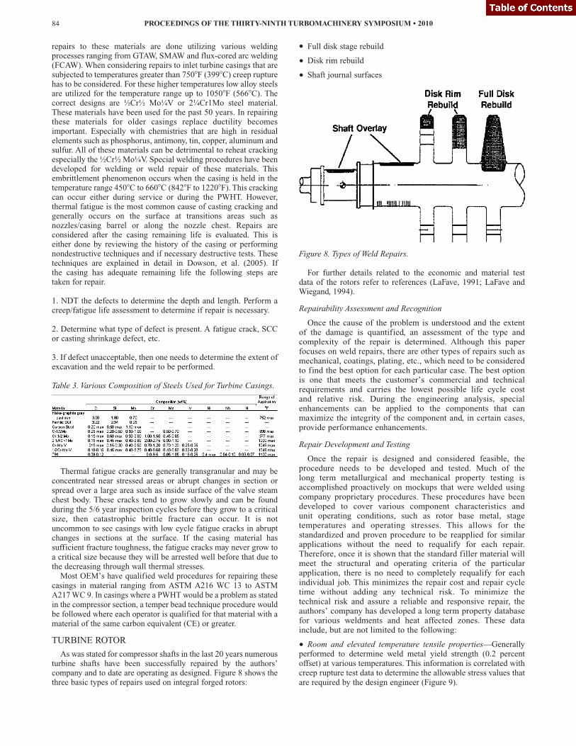
As was stated for compressor shafts in the last 20 years numerousturbine shafts have been successfully repaired by the authors’company and to date are operating as designed. Figure 8 shows thethree basic types of repairs used on integral forged rotors:
Full disk stage rebuild
• Disk rim rebuild• Shaft journal surfaces
Figure 8. Types of Weld Repairs.
For further details related to the economic and material testdata of the rotors refer to references (LaFave, 1991; LaFave andWiegand, 1994).
Repairability Assessment and Recognition
Once the cause of the problem is understood and the extentof the damage is quantified, an assessment of the type andcomplexity of the repair is determined. Although this paperfocuses on weld repairs, there are other types of repairs such asmechanical, coatings, plating, etc., which need to be consideredto find the best option for each particular case. The best optionis one that meets the customer’s commercial and technicalrequirements and carries the lowest possible life cycle costand relative risk. During the engineering analysis, specialenhancements can be applied to the components that canmaximize the integrity of the component and, in certain cases,provide performance enhancements.
Repair Development and Testing
Once the repair is designed and considered feasible, theprocedure needs to be developed and tested. Much of thelong term metallurgical and mechanical property testing isaccomplished proactively on mockups that were welded usingcompany proprietary procedures. These procedures have beendeveloped to cover various component characteristics andunit operating conditions, such as rotor base metal, stagetemperatures and operating stresses. This allows for thestandardized and proven procedure to be reapplied for similarapplications without the need to requalify for each repair.Therefore, once it is shown that the standard filler material willmeet the structural and operating criteria of the particularapplication, there is no need to completely requalify for eachindividual job. This minimizes the repair cost and repair cycletime without adding any technical risk. To minimize thetechnical risk and assure a reliable and responsive repair, theauthors’ company has developed a long term property databasefor various weldments and heat affected zones. These datainclude, but are not limited to the following:
• Room and elevated temperature tensile properties—Generallyperformed to determine weld metal yield strength (0.2 percentoffset) at various temperatures. This information is correlated withcreep rupture test data to determine the allowable stress values thatare required by the design engineer (Figure 9).
PROCEEDINGS OF THE THIRTY-NINTH TURBOMACHINERY SYMPOSIUM • 201084
•
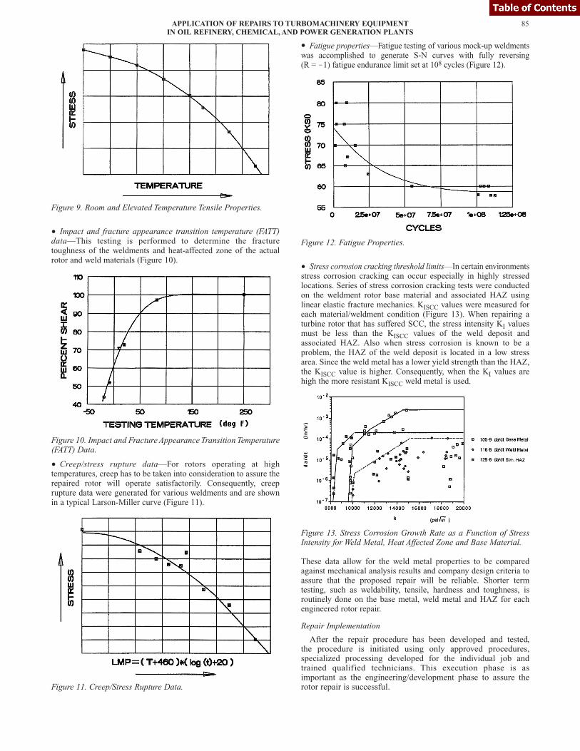
Figure 9. Room and Elevated Temperature Tensile Properties.
• Impact and fracture appearance transition temperature (FATT)data—This testing is performed to determine the fracturetoughness of the weldments and heat-affected zone of the actualrotor and weld materials (Figure 10).
Figure 10. Impact and Fracture Appearance Transition Temperature(FATT) Data.
• Creep/stress rupture data—For rotors operating at hightemperatures, creep has to be taken into consideration to assure therepaired rotor will operate satisfactorily. Consequently, creeprupture data were generated for various weldments and are shownin a typical Larson-Miller curve (Figure 11).
Figure 11. Creep/Stress Rupture Data.
Fatigue properties—Fatigue testing of various mock-up weldmentswas accomplished to generate S-N curves with fully reversing(R = !1) fatigue endurance limit set at 108 cycles (Figure 12).
Figure 12. Fatigue Properties.
• Stress corrosion cracking threshold limits—In certain environmentsstress corrosion cracking can occur especially in highly stressedlocations. Series of stress corrosion cracking tests were conductedon the weldment rotor base material and associated HAZ usinglinear elastic fracture mechanics. KISCC values were measured foreach material/weldment condition (Figure 13). When repairing aturbine rotor that has suffered SCC, the stress intensity KI valuesmust be less than the KISCC values of the weld deposit andassociated HAZ. Also when stress corrosion is known to be aproblem, the HAZ of the weld deposit is located in a low stressarea. Since the weld metal has a lower yield strength than the HAZ,the KISCC value is higher. Consequently, when the KI values arehigh the more resistant KISCC weld metal is used.
Figure 13. Stress Corrosion Growth Rate as a Function of StressIntensity for Weld Metal, Heat Affected Zone and Base Material.
These data allow for the weld metal properties to be comparedagainst mechanical analysis results and company design criteria toassure that the proposed repair will be reliable. Shorter termtesting, such as weldability, tensile, hardness and toughness, isroutinely done on the base metal, weld metal and HAZ for eachengineered rotor repair.
Repair Implementation
After the repair procedure has been developed and tested,the procedure is initiated using only approved procedures,specialized processing developed for the individual job andtrained qualified technicians. This execution phase is asimportant as the engineering/development phase to assure therotor repair is successful.
85APPLICATION OF REPAIRS TO TURBOMACHINERY EQUIPMENTIN OIL REFINERY, CHEMICAL, AND POWER GENERATION PLANTS
•
Each part of the aforementioned rotor restoration philosophy isequally important and must be accomplished in their entirety toassure every major repair is successful and without unnecessaryrisks. The following case study will show how this structuredapproach is put into practice.
CASE STUDY—150 MW IP/LP ROTORS
Background
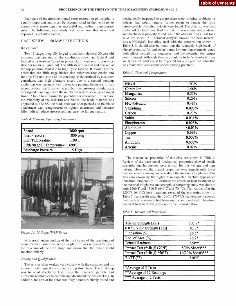
Two 13-stage, integrally forged rotors from identical 30 year oldturbines, that operated at the conditions shown in Table 4 andlocated on a western Canadian power plant, were sent to a serviceshop for repairs (Figure 14). The fifth stage disk rim had cracked atthe top pressure land due to high cycle fatigue. It should also benoted that the fifth stage blades also exhibited root cracks andfretting. The root cause of the cracking, as determined by customerconsultant, was high vibratory stress due to a second bendingmode that was resonant with the nozzle passing frequency. It wasrecommended that to solve the problem the customer should use aredesigned diaphragm with the number of nozzle openings changedfrom 62 to 92 to minimize the potential for resonance. To increasethe reliability of the disk rim and blades, the blade material wasupgraded to 422 SS, the blade root was shot-peened and the bladeattachment was reengineered to tighten tolerances and increasefillet radii to reduce stresses and increase the fatigue margin.
Table 4. Showing Operating Conditions.
Figure 14. 13-Stage IP/LP Rotor.
With good understanding of the root cause of the cracking andrecommended corrective action in place, it was required to repairthe disk rim of the fifth stage and assure that the repair wouldfunction reliably.
Testing and Qualification
The service shop worked very closely with the customer and hisinternal metallurgical consultant during this phase. The first stepwas to nondestructively test, using the magnetic particle andultrasonic techniques to confirm and document the rim cracking. Inaddition, the rest of the rotor was fully nondestructively tested and
mechanically inspected to assure there were no other problems ordefects that would require further repair or render the rotorunserviceable. No other defects were found. The disk rim was thenparted off the first rotor. Half the disk rim was chemically analyzedand mechanical property tested, while the other half was used for aweld test mock-up. Chemical analysis showed the base materialwas a NiCrMoV low alloy steel with the composition shown inTable 5. It should also be noted that the relatively high levels ofphosphorous, sulfur and other tramp low melting elements couldboth affect weldability, toughness, and the potential for temperembrittlement. Although these are high by today’s standards, theyare typical of what could be expected for a 30 year old rotor thatwas made with less sophisticated melting practices.
Table 5. Chemical Composition.
The mechanical properties of this disk are shown in Table 6.Review of the base metal mechanical properties showed tensilestrengths and hardnesses were typical for this vintage and typeturbine. However, the impact properties were significantly lowerthan expected, causing concern about the materials toughness. Thiswas also shown by the higher than expected fracture appearancetransition temperature. To evaluate the effects of heat treatment onthe material toughness and strength, a tempering study was done atboth 1200�F and 1300�F (649�C and 704�C). Test results after the1200�F (649�C) heat treatment revealed the properties shown inTable 7. Test results after the 1300�F (704�C) heat treatment showedthat the tensile strength had been significantly reduced. Therefore,this heat treatment was given no further consideration.
Table 6. Mechanical Properties.
PROCEEDINGS OF THE THIRTY-NINTH TURBOMACHINERY SYMPOSIUM • 201086
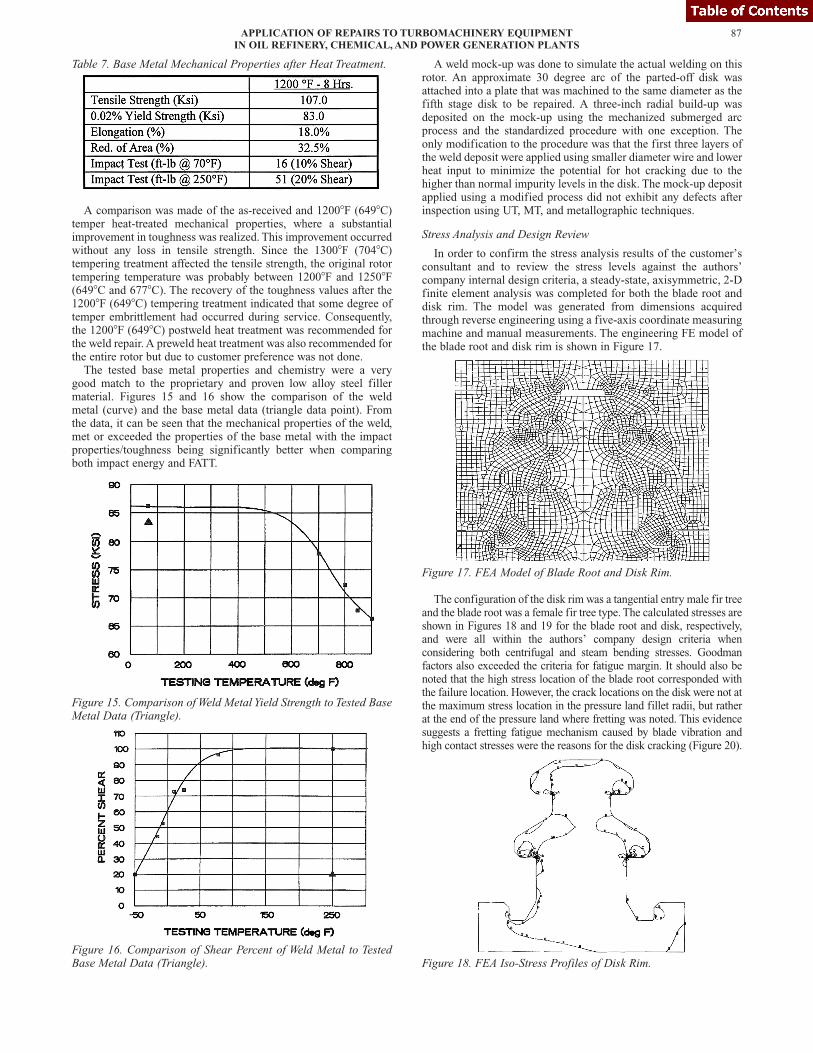
Table 7. Base Metal Mechanical Properties after Heat Treatment.
A comparison was made of the as-received and 1200�F (649�C)temper heat-treated mechanical properties, where a substantialimprovement in toughness was realized. This improvement occurredwithout any loss in tensile strength. Since the 1300�F (704�C)tempering treatment affected the tensile strength, the original rotortempering temperature was probably between 1200�F and 1250�F(649�C and 677�C). The recovery of the toughness values after the1200�F (649�C) tempering treatment indicated that some degree oftemper embrittlement had occurred during service. Consequently,the 1200�F (649�C) postweld heat treatment was recommended forthe weld repair. A preweld heat treatment was also recommended forthe entire rotor but due to customer preference was not done.The tested base metal properties and chemistry were a very
good match to the proprietary and proven low alloy steel fillermaterial. Figures 15 and 16 show the comparison of the weldmetal (curve) and the base metal data (triangle data point). Fromthe data, it can be seen that the mechanical properties of the weld,met or exceeded the properties of the base metal with the impactproperties/toughness being significantly better when comparingboth impact energy and FATT.
Figure 15. Comparison of Weld Metal Yield Strength to Tested BaseMetal Data (Triangle).
Figure 16. Comparison of Shear Percent of Weld Metal to TestedBase Metal Data (Triangle).
A weld mock-up was done to simulate the actual welding on thisrotor. An approximate 30 degree arc of the parted-off disk wasattached into a plate that was machined to the same diameter as thefifth stage disk to be repaired. A three-inch radial build-up wasdeposited on the mock-up using the mechanized submerged arcprocess and the standardized procedure with one exception. Theonly modification to the procedure was that the first three layers ofthe weld deposit were applied using smaller diameter wire and lowerheat input to minimize the potential for hot cracking due to thehigher than normal impurity levels in the disk. The mock-up depositapplied using a modified process did not exhibit any defects afterinspection using UT, MT, and metallographic techniques.
Stress Analysis and Design Review
In order to confirm the stress analysis results of the customer’sconsultant and to review the stress levels against the authors’company internal design criteria, a steady-state, axisymmetric, 2-Dfinite element analysis was completed for both the blade root anddisk rim. The model was generated from dimensions acquiredthrough reverse engineering using a five-axis coordinate measuringmachine and manual measurements. The engineering FE model ofthe blade root and disk rim is shown in Figure 17.
Figure 17. FEA Model of Blade Root and Disk Rim.
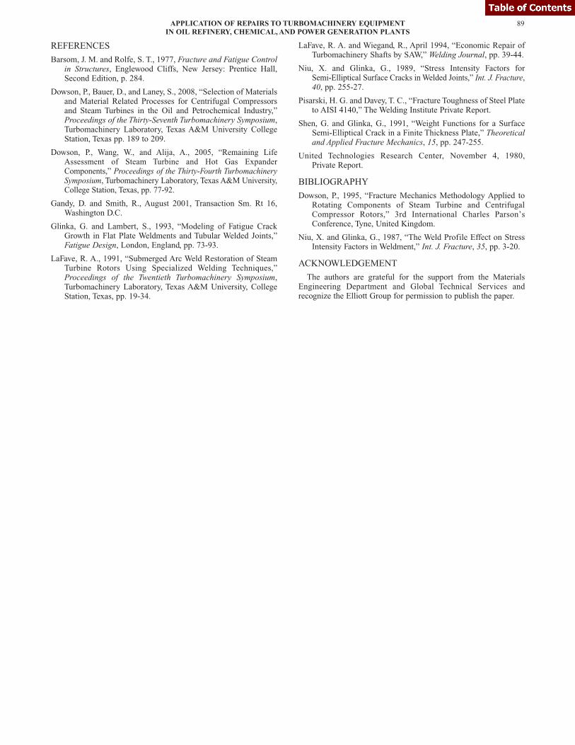
The configuration of the disk rim was a tangential entry male fir treeand the blade root was a female fir tree type. The calculated stresses areshown in Figures 18 and 19 for the blade root and disk, respectively,and were all within the authors’ company design criteria whenconsidering both centrifugal and steam bending stresses. Goodmanfactors also exceeded the criteria for fatigue margin. It should also benoted that the high stress location of the blade root corresponded withthe failure location. However, the crack locations on the disk were not atthe maximum stress location in the pressure land fillet radii, but ratherat the end of the pressure land where fretting was noted. This evidencesuggests a fretting fatigue mechanism caused by blade vibration andhigh contact stresses were the reasons for the disk cracking (Figure 20).
Figure 18. FEA Iso-Stress Profiles of Disk Rim.
87APPLICATION OF REPAIRS TO TURBOMACHINERY EQUIPMENTIN OIL REFINERY, CHEMICAL, AND POWER GENERATION PLANTS
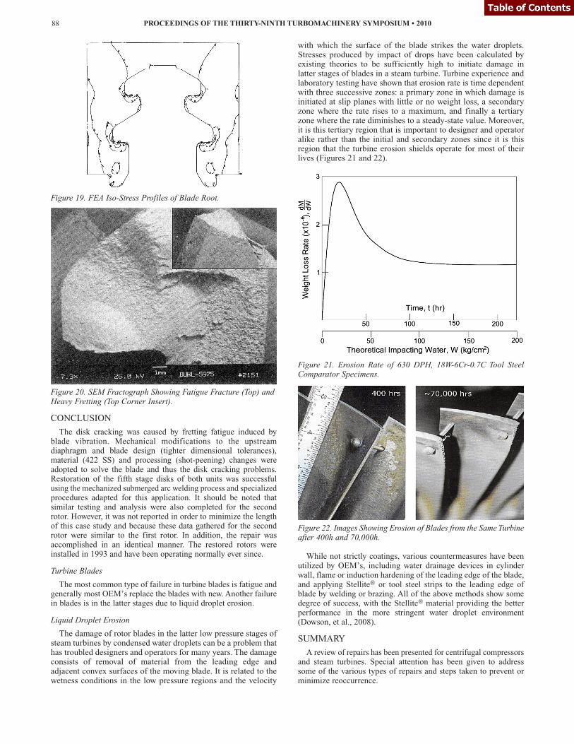
Figure 19. FEA Iso-Stress Profiles of Blade Root.
Figure 20. SEM Fractograph Showing Fatigue Fracture (Top) andHeavy Fretting (Top Corner Insert).
CONCLUSION
The disk cracking was caused by fretting fatigue induced byblade vibration. Mechanical modifications to the upstreamdiaphragm and blade design (tighter dimensional tolerances),material (422 SS) and processing (shot-peening) changes wereadopted to solve the blade and thus the disk cracking problems.Restoration of the fifth stage disks of both units was successfulusing the mechanized submerged arc welding process and specializedprocedures adapted for this application. It should be noted thatsimilar testing and analysis were also completed for the secondrotor. However, it was not reported in order to minimize the lengthof this case study and because these data gathered for the secondrotor were similar to the first rotor. In addition, the repair wasaccomplished in an identical manner. The restored rotors wereinstalled in 1993 and have been operating normally ever since.
Turbine Blades
The most common type of failure in turbine blades is fatigue andgenerally most OEM’s replace the blades with new. Another failurein blades is in the latter stages due to liquid droplet erosion.
Liquid Droplet Erosion
The damage of rotor blades in the latter low pressure stages ofsteam turbines by condensed water droplets can be a problem thathas troubled designers and operators for many years. The damageconsists of removal of material from the leading edge andadjacent convex surfaces of the moving blade. It is related to thewetness conditions in the low pressure regions and the velocity
with which the surface of the blade strikes the water droplets.Stresses produced by impact of drops have been calculated byexisting theories to be sufficiently high to initiate damage inlatter stages of blades in a steam turbine. Turbine experience andlaboratory testing have shown that erosion rate is time dependentwith three successive zones: a primary zone in which damage isinitiated at slip planes with little or no weight loss, a secondaryzone where the rate rises to a maximum, and finally a tertiaryzone where the rate diminishes to a steady-state value. Moreover,it is this tertiary region that is important to designer and operatoralike rather than the initial and secondary zones since it is thisregion that the turbine erosion shields operate for most of theirlives (Figures 21 and 22).
Figure 21. Erosion Rate of 630 DPH, 18W-6Cr-0.7C Tool SteelComparator Specimens.
Figure 22. Images Showing Erosion of Blades from the Same Turbineafter 400h and 70,000h.
While not strictly coatings, various countermeasures have beenutilized by OEM’s, including water drainage devices in cylinderwall, flame or induction hardening of the leading edge of the blade,and applying Stellite® or tool steel strips to the leading edge ofblade by welding or brazing. All of the above methods show somedegree of success, with the Stellite® material providing the betterperformance in the more stringent water droplet environment(Dowson, et al., 2008).
SUMMARY
A review of repairs has been presented for centrifugal compressorsand steam turbines. Special attention has been given to addresssome of the various types of repairs and steps taken to prevent orminimize reoccurrence.
PROCEEDINGS OF THE THIRTY-NINTH TURBOMACHINERY SYMPOSIUM • 201088
REFERENCES
Barsom, J. M. and Rolfe, S. T., 1977, Fracture and Fatigue Controlin Structures, Englewood Cliffs, New Jersey: Prentice Hall,Second Edition, p. 284.
Dowson, P., Bauer, D., and Laney, S., 2008, “Selection of Materialsand Material Related Processes for Centrifugal Compressorsand Steam Turbines in the Oil and Petrochemical Industry,”Proceedings of the Thirty-Seventh Turbomachinery Symposium,Turbomachinery Laboratory, Texas A&M University CollegeStation, Texas pp. 189 to 209.
Dowson, P., Wang, W., and Alija, A., 2005, “Remaining LifeAssessment of Steam Turbine and Hot Gas ExpanderComponents,” Proceedings of the Thirty-Fourth TurbomachinerySymposium, Turbomachinery Laboratory, Texas A&M University,College Station, Texas, pp. 77-92.
Gandy, D. and Smith, R., August 2001, Transaction Sm. Rt 16,Washington D.C.
Glinka, G. and Lambert, S., 1993, “Modeling of Fatigue CrackGrowth in Flat Plate Weldments and Tubular Welded Joints,”Fatigue Design, London, England, pp. 73-93.
LaFave, R. A., 1991, “Submerged Arc Weld Restoration of SteamTurbine Rotors Using Specialized Welding Techniques,”Proceedings of the Twentieth Turbomachinery Symposium,Turbomachinery Laboratory, Texas A&M University, CollegeStation, Texas, pp. 19-34.
LaFave, R. A. and Wiegand, R., April 1994, “Economic Repair ofTurbomachinery Shafts by SAW,” Welding Journal, pp. 39-44.
Niu, X. and Glinka, G., 1989, “Stress Intensity Factors forSemi-Elliptical Surface Cracks in Welded Joints,” Int. J. Fracture,40, pp. 255-27.
Pisarski, H. G. and Davey, T. C., “Fracture Toughness of Steel Plateto AISI 4140,” The Welding Institute Private Report.
Shen, G. and Glinka, G., 1991, “Weight Functions for a SurfaceSemi-Elliptical Crack in a Finite Thickness Plate,” Theoreticaland Applied Fracture Mechanics, 15, pp. 247-255.
United Technologies Research Center, November 4, 1980,Private Report.
BIBLIOGRAPHY
Dowson, P., 1995, “Fracture Mechanics Methodology Applied toRotating Components of Steam Turbine and CentrifugalCompressor Rotors,” 3rd International Charles Parson’sConference, Tyne, United Kingdom.
Niu, X. and Glinka, G., 1987, “The Weld Profile Effect on StressIntensity Factors in Weldment,” Int. J. Fracture, 35, pp. 3-20.
ACKNOWLEDGEMENT
The authors are grateful for the support from the MaterialsEngineering Department and Global Technical Services andrecognize the Elliott Group for permission to publish the paper.
89APPLICATION OF REPAIRS TO TURBOMACHINERY EQUIPMENTIN OIL REFINERY, CHEMICAL, AND POWER GENERATION PLANTS

PROCEEDINGS OF THE THIRTY-NINTH TURBOMACHINERY SYMPOSIUM • 201090