Embed Size (px)
Citation preview

APPLICATION OF THE INTERFEROMETER TO MEAS-UREMENTS OF THE THERMAL DILATATION OFCERAMIC MATERIALS.
By George E. Merritt.
ABSTRACT.
An interference method and apparatus for measuring the thermal expansion of
ceramic materials are described. The samples in the form of tripods or small pins,
0.5 to 10.0 mm in length, are placed between two fused quartz interferometer
plates and heated in an electric furnace. The elongation of the sample is deter-
mined from the number of interference fringes that pass reference marks on the
upper interferometer plate. Measurements made on the thermal expansion of
several samples of glaze, terra cotta, tile, porcelain, and clay show that this methodgives accurate and reproducible results. These, represented by curves, show that
the expansivities of different ceramic materials may differ greatly ; that the expan-
sion of a given material may be different at different parts of the temperature scale;
and that some materials may undergo permanent dimensional changes when sub-
jected to heat treatment. They also serve to explain why some materials fail andothers do not when subjected to the same treatment and emphasize the need of
accurate data on expansivity of each material if it is to be subjected to suddentemperature changes when combined with another material differing in composition.
CONTENTS.Page.
I. Introduction 357II . Experimental method 358
1. Fizeau method 358
2. Three-pin method 359III. Description of apparatus 359
1. Interferometer and specimens 3592. Furnace 360
IV. Experimental procedure 362
1. Optical adjustments 362
2. Temperature regulation and observation 362
V. Experimental results 362
VI. Summary 372
I. INTRODUCTION.
The dimensional change with variation in temperature deter-
mines, to a large extent, the behavior of ceramic materials during
the process of manufacture and also affects the quality, durability,
and resistance of the finished product.
When clay products, such as terra cotta, tile, porcelain, etc., are
cooled rather quickly in the furnace, cracks may develop arising
from the outer layer contracting at a different rate than the inner
357

3 58 Scientific Papers cf the Bureau of Standards. [VoLiq
mass, which is at a higher temperature. If more than one mate-
rial is used (as in the case of glazed ware), the expansivities of
the materials should be identical below the annealing range of the
material possessing the lower one, or strains are likely to be set
up during cooling which later produce cracks in the glaze, andmay even cause it to scale off. Accurate data on the expansion
over the entire working range of temperature is essential for the
best choice and manipulation of the materials.
The present investigation was undertaken for the dual purpose of
proving the applicability of the interference method to this prob-
lem, where it is often necessary to work with very small samples
of the material, and at the same time of determining the thermal
expansivity of some ceramic materials over a large temperature
range. Measurements were made on several different samples of
glaze, tile, porcelain, and terra cotta in the temperature interval
20 to 950 C. The effect of heating the sample at different rates
and of taking it over the same range several times was also in-
vestigated.
II. EXPERIMENTAL METHOD.
1. FIZEAU METHOD.
The interference method as originated by Fizeau 1 and later
developed by Pulfrich 2 was particularly adapted to this work be-
cause the extreme sensitiveness of the interferometer makes it
possible to work with a small specimen of the material, and be-
cause the small size of this apparatus simplifies the problem of uni-
form heating and temperature control . By this method the change
in length of a ring or tripod of the material used as a separator for
the interferometer plates is determined from the shift of the
straight interference fringes past a reference mark ruled in the
center of the lower surface of the upper plate. These fringes pro-
duced by interference of the light reflected from the interior faces
of the two interferometer plates are observed with a Pulfrich 3 ap-
paratus. Any elongation or contraction ±AL in the length, L,
of the specimen which forms a separator for these two faces causes
a corresponding movement of the interference fringes past the
reference mark.
In passing from one temperature t, with the plates at a distance
apart equal to L, to a second temperature t + At with the plates at
1 Fizeau Ann. d. Phys., 128, p. 564; 1866. 3 C. Pulfrich Zeits. f . Instrk., No. 9; 1898.
2 Pulfrich Zeits. f. Instrk., 13, p. 365; 1893.

Merritt) Thermal Expansion of Ceramic Materials. 359
a distance equal to L + AL, a band passes the reference mark
each time the total number of wave lengths in the path (double
distance) increases by one. The number of bands AiV that pass
is then obviously equal to the difference in the number of wave
lengths in the double distance under the two conditions. If X
represents the wave length of the light then
at *AN, [AL =-—— (1)
2
and the mean coefficient of expansion
C-*** (2)U 2LM ^'
Since the observations are made at the reference mark, the
quantity AL is the change in the distance between the two plates
at that point, and this is equal to change in length of the three
corners of the tripod, providing their behavior is identical ; other-
wise it approximates their mean elongation if the}^ behave differ-
ently.2. THREE-PIN METHOD.
In afurther modification of the interference method developed byPeters 4 three entirely separate pins are used as separators for the
plates instead of a tripod or ring. The pins are made in the form of
cones, about 4 mm across the base and from 2 to 10 mm in height.
The exact change in length of each individual pin is determined
from the number of fringes that pass the point of contact of that
pin with the upper plate. The advantages of this modification are
that extremely small samples can be used, and three samples from
different specimens or from different parts of the same specimen
can be investigated simultaneously.
III. DESCRIPTION OF APPARATUS.
1. INTERFEROMETER AND SPECIMENS.
The two plates A and B of the interferometer represented in
Figure 1 were made of fused quartz, which can be heated to
i,ooo° C. without serious injury to the surfaces. The upper
surface of the base plate B was polished true plane, while the
lower surface was left in the ground condition to eliminate reflec-
tion therefrom. Both surfaces of A were polished true plane,
4 Peters, Jour. Wash. Acad. Sci., 9, No. 10, p. 281; 1919.

360 Scientific Papers of the Bureau of Standards. [Vol. i9
making an angle of about 20 seconds with each other, so that
light reflected from the upper surface could be diaphragmed out
of the field of view. The separator 5, the test piece or pieces,
consisted either of a triangle of the porcelain or other clay with
feet at the corners and a hole in the middle through which to view
the fringes, or of three separate fragments or pins of the material
to be tested.
In case the individual expansions of the pins are to be measured,
it is important that the shadow outline of each pin be small and
round, or at least regular in form, and that the point of contact
with the upper plate be in the center of
this shadow, because this locates the
point of contact which can not itself be
seen. Where an average of three sam-
ples is to be taken from readings on
a central reference mark R, these may-
be of any shape, even rough fragments,
the requisites being that each stand
solidly alone; that all have practically
equal lengths; and that their points of
contact with the upper plate be about
the same distance from the reference
mark. Where heating is to be rapid, they
should also be of nearly equal mass.
2. FURNACE.
A sectional view of the electric fur-
nace containing the interferometer is
given in Figure 2. A porcelain tube
F, 5 cm in diameter and 30 cm long,
wound spirally with a heating coil K, is mounted vertically
in a sheet-iron jacket and surrounded with insulating ma-
terial. A smaller procelain tube E, which extends from
the base to about 3 cm from the center of the furnace, sup-
ports the porcelain disk D, the space below this disk being
filled with an insulating material. A porcelain cup C, with a
cover H, acts as a container for the interferometer A S B and
can be lowered into the furnace by a platinum wire until it rests
on the disk D. A small double-bore porcelain tube containing
the thermocouple T passes through the base of the furnace, the
disk D, and the bottom of the cup C, the thermocouple junction
being adjusted so that it nearly touches the lower interferometer
plate B. The upper end of the furnace tube is closed by another
Fig. i.—Interferometer.

Merrill) Thermal Expansion of Ceramic Materials. 36i
porcelain tube containing the fused quartz windows Wt and
W2 , while W3 is a glass window in a sheet of asbestos board.
The Pulfrich apparatus, using the yellow radiation from
helium for illuminating the interferometer and an optical arrange-
ment for measuring the displacement of the fringes, is represented
by P.
Fig. 2.
—
Electricfurnace.
The heating coil K, which has a resistance of 17 ohms, is
designed to operate on a no-volt circuit with an ammeter and
suitable rheostat to regulate the current. - A current of 4 amperes
is sufficient to heat the furnace from room temperature to 700
C. at the average rate of about 4 C. per minute.

362 Scientific Papers of the Bureau of Standards. [va. 19
IV. EXPERIMENTAL PROCEDURE.
1. OPTICAL ADJUSTMENTS.
The sample having been prepared in the shape of a tripod, or
the three samples for the separate pins having been selected andreduced to similar shape, the distance between bearing points of
the two ends of each is carefully measured with a micrometer.
When these measurements show equality, the specimen is inserted
between the interferometer plates, and the resulting fringes
brought to the desired width by abrasion of one of the contact
points on a dry oilstone.
2. TEMPERATURE REGULATION AND OBSERVATION.
The heating current was regulated to a very nearly constant
temperature rate throughout the run—usually 2.5 to 3 per
minute. The expansion of the sample, due to this heating,
caused the interference fringes to move across the field, and the
number that passed the reference mark were counted. Starting
at room temperature (20 C), thermocouple indications of the
temperature were observed at the moment of transit of definite
fringes across the reference mark. Such readings were usually
made on every fifth fringe.
The upper temperature limit to which the different samples
were heated ranged between 600-970° C. On reaching this limit
the heating current was reduced so as to allow the samples to
cool at the same rate. Observations during contraction were
made as during the heating process.
V. EXPERIMENTAL RESULTS.
Figures 3 to 14 give a graphical representation of the results
obtained from various selected materials. In these the elonga-
tion AL of samples 1 cm in length are plotted as ordinates and the
temperature (in degrees centigrade) as abscissas.
In many of these curves the slope is neither constant nor con-
stantly increasing, and in both clays and glazes the changes maybe abrupt. Many of the clays show sudden increases in the rate
of expansion in the neighborhood of 575 C. These are probably
due to the oc <=±p quartz transformation which occurs at this tem-
perature. In the case of the glazes (that is, glasses), however, the
increase in the rate of^ expansion which takes place anywhere
between 300 and 700 ° C. is due to some readjustment always
related to the softening of the material. As in the case of true

Merrill) Thermal Expansion of Ceramic Materials. 363
glass, the temperature where the rapid increase in expansion
begins is within the annealing range, and below this temperature
any deformation in the glaze practically ceases.
Figure 3 represents the average heating and cooling curves of
three samples (11 mm in length) taken from a terra-cotta tile.
It exhibits the usual relation between the heating and cooling
curves which for fully matured ware are similar in shape and
parallel to each other. For the purpose of matching bodies with
glazes it shows that heating curves may be used with as muchconfidence as cooling curves.
60
40
£0
10
y<y^^*M/
O Heating
GJ Cooling
V^ 100 200 300 400 500 600 700
Degrees Centigrade
Fig. 3.
—
Thermal dilatation of terra-cotta tile.
Figure 4, curve 2, shows the expansion of a terra-cotta brick
and curve 3 the expansion of its glaze. This glaze seemed to be
in good condition, but on being heated to 125 C. and plunged
into cold water (20 C.) it crazed immediately. This was caused
by the strains introduced, due to the difference in expansivities of
the materials when initially cooled from the temperature where
the glaze became hard, and also by the very different rate of
expansion and contraction that exist in the region of sudden
quenching. The data for these curves was obtained from speci-
mens of the material 0.41 mm long chipped from a finished tile.
72910°—24 2

364 Scientific Papers of the Bureau of Standards. [Vol. 19
50
10
y¥
/a
/j
Terra Cotta
XGlaxe
100 £00 300 400 500 600 700
Degrees Centigrade
Fig. 4.
—
Thermal dilatation of terra-cotta tile and glaze.
60
40
13
^^/
/*
^4
/s
/S
O Terra Cotta
X Glaze
100 300 400 600 600 700
Degrees Centigrade
FlG. 5.
—
Thermal dilatation of terra-cotta tile and glaze.

Merritt] Thermal Expansion of Ceramic Materials. 365
Figure 5 represents the expansion of other samples of tile andglaze 0.37 mm in length taken from the same brick from which
the sample of Figure 4 was taken. The same differences in the
expansivities of tile and glaze are shown by both sets of samples.
The differences between the two expansion curves of the glaze
or tiles are not due to inaccuracies of measurement, as each curve
is the average of two runs on the same samples, and differences
between the individual observations were much less than dif-
ferences between the results for the two samples.
to
-
40
30
T>
SO
re
10
O T«rra Cotta
x a Qlaie
500 600 TOO
Degrees Centigrade
Fig. 6.
—
Thermal dilatation of architectural terra-cotta tile and glaze.
Figure 6 shows the expansion curves of a glazed architectural
terra-cotta ornament. Curve 6 for the terra cotta was obtained
from three fragments of 12.03 mm m length. The three samples
of glaze were each 1.27 mm in length, and their expansions were
measured individually by the three-pin method. Although these
curves for tile and glaze seem to match at lower temperatures there
is a marked divergence in the region above 6oo° C. This speci-
men failed in use, the glaze crazing badly and the body crumbling
on exposure to the weather. Possibly slower cooling in the re-
gion near 6oo° would have prevented the failure, as this would
have given the glaze a chance to anneal. This figure is a good
instance of a pair of materials which seem to match when only the
lower part of the expansion curve is known, but exhibit marked
divergence at higher temperatures.

366 Scientific Papers of the Bureau of Standards. [Vol. zq
Figure 7 shows the results from a terra-cotta brick and its
glaze which stood the quenching test exceptionally well. Waremade out of these materials was heated to 125 and then plungedinto cold water. No crazing was visible until after the fifth
repetition of this treatment. The curve for the glaze represents
the average expansion of three samples 0.44 mm in length chipped
from a tile. The three fragments of the body 9.95 mm long
were broken from the same tile. These curves illustrate the agree-
ments of the expansivities of body and glaze that make a product
that will be permanent and resist sudden temperature changes.
60
40 ^e^
»0
6/^/no
/*/9
10
^y'
G Terra Cotta
X frieze
100 200 400 600 600 700
Degrees Centigrade
Fig. 7.
—
Thermal dilatation of terra-cotta tile and glaze.
Figure 8 represents the thermal expansions of two different
glazes of unknown composition. Curve 11 is the result of ob-
servations on samples of 0.48 mm long taken from a finished
specimen, while curve 10 was obtained from three lumps of glaze
material 6.95 mm long. They show the applicability of the
method to small samples in that the results of observations on
the small specimens are as regular as those of the longer.
The curves of Figure 9 represent the thermal expansions of
two samples 1 cm in length cut from the same hollow tile, curve
12 representing the expansion perpendicular to the direction of
flow and curve 13 that parallel to the direction of flow.

Merrm Thermal Expansion of Ceramic Materials. 367
10
S
\y
^t^sIq
y .
^j-s°
O Sample 6.96 mm long
X Sample 0.46 am long
600 700 wDegrees Centigrade
Fig. 8.
—
Thermal dilatation of glaze.
600 »oo
Degrees Centigrade
Fig. 9.
—
Thermal dilatation of hollow tile.
368 Scientific Papers of the Bureau of Standards. [Vol. 10
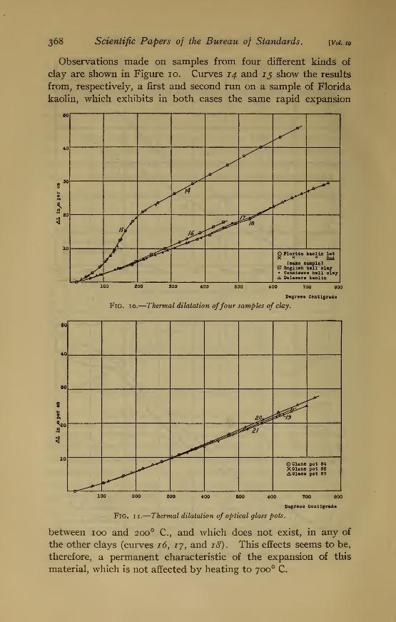
Observations made on samples from four different kinds of
clay are shown in Figure 10. Curves 14 and 15 show the results
from, respectively, a first and second run on a sample of Florida
kaolin, which exhibits in both cases the same rapid expansion
to
40
30
£0
10
«^#
/ 16^*
/^ O Florida kaolin letX "2nd
(seme sample)English ball clay
• Tenniseee ball olay& Delaware kaolin
ZOO 400 600 600 700 800
Degrees Centigrade
Fig. 10.
—
Thermal dilatation offour samples of clay.
60
80
s*<
0.
-a
3
£0^ Z&I9
^tr
0.0
O Glass pot 84XGlese pot 85A Glass pot 87
700 800
Degrees Centigrade
Fig. ii.—Thermal dilatation of optical glass pots.
between ioo and 200 C, and which does not exist, in any of
the other clays (curves 16, ij, and 18). This effects seems to be,
therefore, a permanent characteristic of the expansion of this
material, which is not affected by heating to 700 C.

Merritt) Thermal Expansion of Ceramic Materials. 369
The curves of Figure 11 represent the thermal expansions of
three fragments taken from each of three pots in which optical
glass has been melted.
The following table gives the batch analysis of these pots
:
TABLE 1.—Batch Analysisi of Bureau of Standards Glass Pots.
Material.
Samples—
84 85 87
FeldsparPer cent.
61010
2iy,siy2
Per cent.4
169
2150
Per cent.4
Tennessee ball clay.
.
16Kentucky ball clay 9Kaolin 21
Grog1 50
1 Grog: 50 per cent Tennessee ball clay, 50 per cent kaolin.
Samples 85 and 87 are of the same composition, but 85 was
cooled rapidly and 87 very slowly after the glass was melted.
The cooling rate of 84 lay between the rates of the other two.
With all three pots the three samples taken from each pot were
found to have very nearly identical expansion, thus indicating
that a homogeneous mixture had been obtained.
50
**0 / •—
\
s*A '\
^^o^- ©first run \
X 3eoond run \
A Third run \
°^10 2C 3v)0 4 X> 6 30 606 70 806
Dtgreea Centigrade
FlG. 12.
—
Thermal dilatation of unburned clay.
Figures 12, 13, and 14, represent the mean results obtained
from eight consecutive runs on the same three samples of un-
burned clay, illustrating successive changes in the material due
to heating. These samples were in the shape of cones rounded
at the top and almost as wide as high. Their length when green

37Q Scientific Papers of the Bureau of Standards. [Vol. iQ
was 9.53 mm after drying at room temperature. With exception
of the fourth and fifth runs all were heated at 2.5 ° per minute.
The crook in curve 22, representing the first run, beginning at
90 and continuing for some distance above 200 , does not
reappear in any of the subsequent heatings and is probably
connected with the liberation of moisture by the green samples.
Above 500 C, which is the temperature at which kaolin begins
to lose chemically combined water, all three specimens began to
shrink rapidly, the interference fringes becoming very narrow
due to the unequal contraction of the three pins, making it very
difficult to count the number of fringes that passed the reference
mark. The values given above 500 are, therefore, only a close
approximation. Near 575 the expansion began again and con-
50
f ZP****. K
40
/#£*~T$
•4(1
r^
to
10 4 *^Z0^ O Fourth run,heating
4?ourth rua.oooling
X fifth ran
100 200 SCO 400 60O 600 700 800
Degress Centigrade
Fig. 13.
—
Thermal dilatation of unburned clay.
tinued up to a temperature of 66o° C, from which point on con-
traction took place at a uniform rate. On returning to roomtemperature the samples were measured with a micrometer and
found to be 9.45 mm in length, the heat treatment having short-
ened them 0.08 mm, or about 0.8 per cent. The samples were
again adjusted (length 9.40 mm) and replaced in the furnace
for further examination. Curve 23, Figure 12, shows the results
of a second run. In this run they were heated to 650 C.without
any contraction taking place. An appreciable increase in the
expansion occurred between 560 and 600° C, which is the region
of the second expansion during the first run. A more markedincrease in the expansion occurred during the third run (curve
24) on passing through the same temperature region. Above

Merritt) Thermal Expansion of Ceramic Materials. 37i
6oo° the rate decreased, and at 750 contraction began. Curve
25 of Figure 13 represents the results obtained during both heating
and cooling of the fourth run in which the samples were heated
at the rate of 3.7 C. per minute and cooled at 2.6 C. per minute.
Curve 26 gives the results of a fifth run when the heating rate
was 2 per minute. The three curves obtained from the third,
fourth, and fifth runs are very similar, showing an. increase in
the rate of expansion near 350 C, another at 560 C, and a
rapid decrease above 6oo° C.
Curve 27, Figure 14, represents the results of a sixth run in
which the samples were carried up to 970 C. Up to 806 ° C,
50
10
?
3
-so
t\ ^wi*~e*ZZ
IB
/\3
*^"
\ 1
/2Zpr /
\s~\ \/^K
0^\
J \Z7
1
1
1
• 1st run ©7th run
A 6th run X8th run\ ^1 i—
100 400 500 900 800 900 1000
Degrees Centigrade
Fig. 14.
—
Thermal dilatation of unburned clay.
which was the highest temperature that had previously been
reached, it has the same form as the curves from the three pre-
ceding runs. Between 806 and 970 C, the samples shortened
rapidly. This shortening was similar in effect to that which
occurred above 500 during the first run. After being held at
970 C. for a half hour and then cooled to room temperature the
samples measured 9.24 mm in length as compared with the initial
value of 9.40 mm, showing a permanent shrinkage of 0.16 mm,or 1.7 per cent.
The results of the seventh and eighth runs are represented bycurves 28 and 29, Figure 14. These are almost identical, but

372 Scientific Papers of the Bureau of Standards. [Vol. 19
differ from any of the preceding ones. No shrinkage occurred at
850 nor any change in the expansion at 350 . The rapid increase
in expansion between 560 and 6oo° C. was, however, still present.
This increase is very similar in its effect on the expansivity to
that of glass on passing through its "critical region."
With the reproduction of curve 22 on this plot the curves of
Figure 14 summarize the results obtained from this clay. Curve
22 represents the first run (on the green clay) and shows the
rapid contraction between 500 and 806 C. The part of curve
27 below 8oo°, which is typical of the curves obtained from the
second, third, fourth, fifth, and sixth runs, shows contraction had
been eliminated by this first heat treatment. On heating to still
higher temperatures, however, the contraction reappeared. Thelast two curves (28 and 20) show that the heat treatment up to
970 C. had made the expansivity of the material quite regular
and reproducible below this temperature.
VI. SUMMARY.
In the making of clay products, which may differ greatly in
composition and which must stand large variation in tempera-
ture both during the process of manufacture and in use, an accu-
rate knowledge of the thermal expansions of the materials and
of different parts of the finished product is very essential. Since
it is often inconvenient or impossible to obtain large samples of the
material, a very sensitive method is necessary for making the
measurements. The interference method described in this paper
is particularly well adapted for this work, because samples rang-
ing in length from 0.5 to 10 mm can be measured with sufficient
accuracy. With this method the dimensional change of the
samples for any temperature interval is given by the number of
fringes, produced by the yellow radiation from a helium source,
which pass a reference mark on the front interferometer plate.
In order to show the need of accurate knowledge of the expan-
sion and prove the applicability of the interference method,
observations were made in the temperature region between 20
and 970 C. on a variety of ceramic materials consisting of several
different samples of glaze, terra-cotta, tile, porcelain, glass pots,
and unburned clay.
The results of this investigation show that different ceramic
material may differ greatly in expansivity; that the expansivity
of a given material may be very different at different parts of the
Merritt] Thermal Expansion of Ceramic Materials. 373
temperature scale; and that a material may undergo permanent
dimensional changes when subjected to heat treatment. Theneed for extensive measurements on the expansion of each mate-
rial is therefore apparent. The consistency and reproducibility of
the results obtained on seasoned samples, even when they are
less than 1 mm in length, and the facility with which measure-
ments can be made over a temperature interval of i,ooo° C.
shows that the interference method is sufficiently accurate for
making the measurements and particularly well adapted for
studying the homogeneity of any given mass.
Washington, September 28, 1923.


I
II
mum ' wtmi
l
.-<
ran
H .*
n ^M
iurn
1; j'ir^ftK;
v^^^i