Embed Size (px)
Citation preview

Application Specific Secure Grouping of Vehicles
in
Vehicular Ad-hoc Network
Ambuj Kumar(Roll No. 211CS2278)
Department of Computer Science and EngineeringNational Institute of Technology Rourkela
Rourkela – 769 008, India

Application Specific Secure Grouping of Vehiclesin
Vehicular Ad-hoc Network
Thesis submitted in partial fulfillment
of the requirements for the degree of
Master of Technology
in
Computer Science and Engineering Department
(Specialization: Information Security)
by
Ambuj Kumar
(Roll No: 211CS2278)
under the guidance of
Prof. Ashok Kumar Turuk
Department of Computer Science and Engineering
National Institute of Technology, Rourkela
Rourkela - 769008, Odisha, India
June, 2013

Dedicated to my family

Computer Science and EngineeringNational Institute of Technology RourkelaRourkela-769 008, India. www.nitrkl.ac.in
May 22, 2013
Certificate
This is to certify that the work in the thesis entitled Application Specific
Secure Grouping of Vehicles in Vehicular Ad-hoc Network submitted
by Ambuj Kumar is a record of an original work carried out by them under
my supervision and guidance in partial fulfillment of the requirements for the
award of the degree of Master of Technology with specialization of Information
Security in Computer Science and Engineering Department, National Institute of
Technology, Rourkela. Neither this thesis nor any part of it has been submitted
for any degree or academic award elsewhere.
Ashok Kumar Turuk
Professor
Computer Science and Engineering, NIT Rourkela
Acknowledgment
I would like to express my deep gratitude to all who have supported and
encouraged me in various ways. This dissertation would not have been possible
without you.
Foremost, I would like to express my deep gratitude to my advisor, Prof. Ashok
Kumar Turuk for providing me with a platform to work on very exciting field
of Vehicular Ad-hoc Network. His untiring effort, commitment, encouragement,
guidance and support helped me in understanding and giving word to my research.
I am gratified to Prof. Sanjay Kumar Jena and Prof. Banshidhar Majhi,
who has provided me with continuous encouragement and advised me at different
stages of the thesis work.
I am very much indebted to all the Professors of computer Science Department
for their advice and insightful comments at different stages of thesis that were
indeed thought provoking.
I would like to thank my friends for their support. I especially want to thank
Alekha kumar Mishra, Harun Rashid, and R. P. Nayak for all the help, moral and
intellectual over the year.
Most importantly, this would not have been possible without the love and
support of my family. My family, whom this thesis is dedicated to, has been a
constant source of love, concern, support and strength all these years. I would
like to express my heart-felt gratitude to them. There have been ups and there
have been downs and the cycle is likely to continue.
Ambuj Kumar
Email: [email protected]

Abstract
Providing efficient, secure and reliable communication among vehicles is
complicated and challenging problem. Vehicles communicate with each other
(V2V communication) and Road Side Infrastructure (V2X communication) unit
to provide convenient, safety and commercial service to the travelers. Similar
information shared by each vehicle within close proximity creates huge network
congestion. Grouping of vehicles reduces dropping of packets due to collision of
sending large number of duplicate packets. Grouping concept is used in our thesis
to provide different applications of VANET in a better way. We have modified
grouping of vehicles according to our applications requirement and proposed an
approach for vehicles to select real-time adaptive path. Vehicles choose congestion
free and shortest time path to their destination. In the next section, grouping of
vehicles are used to transmit event-driven safety message in emergency situations.
Grouping of vehicles is efficient in this case as it needed to be very fast and highly
reliable. We have added different parameters for transmitting the message to
neighbors which makes it more efficient. It uses decentralized environment as it
needed to works both for highway and urban scenario of the city. It helps to
improve security in the message and privacy of entities in an efficient manner
which are major concern in achieving robust vehicular network.In testing phase,
we evaluated the performance of our proposed approach with help of VANET
simulators (OMNET++, SUMO, Veins) and compared ours proposed approach
with other existing methods.

Contents
Certificate ii
Acknowledgement iv
Abstract v
List of Figures viii
List of Tables x
1 Introduction 1
1.1 VANET and Group Communication . . . . . . . . . . . . . . . . . . 2
1.2 Problem Definition . . . . . . . . . . . . . . . . . . . . . . . . . . . 3
1.3 Motivation . . . . . . . . . . . . . . . . . . . . . . . . . . . . . . . . 4
1.4 Objective . . . . . . . . . . . . . . . . . . . . . . . . . . . . . . . . 4
1.5 Thesis Organization . . . . . . . . . . . . . . . . . . . . . . . . . . . 4
2 Background 6
2.1 VANET Introduction . . . . . . . . . . . . . . . . . . . . . . . . . . 7
2.2 Applications . . . . . . . . . . . . . . . . . . . . . . . . . . . . . . . 9
2.3 Protocols and Recent Projects . . . . . . . . . . . . . . . . . . . . . 10
2.4 Main Challenges of VANET . . . . . . . . . . . . . . . . . . . . . . 12
2.4.1 Technical Challenges . . . . . . . . . . . . . . . . . . . . . . 13
2.4.2 Socioeconomic Challenges . . . . . . . . . . . . . . . . . . . 13
2.5 Mobility Modeling . . . . . . . . . . . . . . . . . . . . . . . . . . . 14
vi

3 Real-time Adaptive Path Selection by Vehicles in VANET 15
3.1 Introduction . . . . . . . . . . . . . . . . . . . . . . . . . . . . . . . 16
3.2 Literature survey . . . . . . . . . . . . . . . . . . . . . . . . . . . . 18
3.3 Proposed Protocol Model . . . . . . . . . . . . . . . . . . . . . . . . 19
3.3.1 VANET Architecture . . . . . . . . . . . . . . . . . . . . . . 19
3.3.2 Assumptions . . . . . . . . . . . . . . . . . . . . . . . . . . . 19
3.3.3 Network Model . . . . . . . . . . . . . . . . . . . . . . . . . 20
3.3.4 Route Selection Algorithm . . . . . . . . . . . . . . . . . . . 24
3.4 Results and Discussion . . . . . . . . . . . . . . . . . . . . . . . . . 30
3.4.1 Grid map Scenario . . . . . . . . . . . . . . . . . . . . . . . 32
3.4.2 Realistic Road Traffic- NIT Rourkela Street Map . . . . . . 33
4 An Efficient Safety Message Transmission Protocol for VANET 35
4.1 Introduction . . . . . . . . . . . . . . . . . . . . . . . . . . . . . . . 36
4.2 Literature survey . . . . . . . . . . . . . . . . . . . . . . . . . . . . 37
4.3 Proposed Protocol Model . . . . . . . . . . . . . . . . . . . . . . . . 39
4.3.1 Group Formation . . . . . . . . . . . . . . . . . . . . . . . . 39
4.3.2 Group Leader Selection . . . . . . . . . . . . . . . . . . . . . 41
4.3.3 ESM Message Transmission . . . . . . . . . . . . . . . . . . 42
4.3.4 ESM Message Transmission Using Priority and Context-
based communication: . . . . . . . . . . . . . . . . . . . . . 44
4.4 Ensuring ESM message security . . . . . . . . . . . . . . . . . . . . 45
4.4.1 Security Requirements . . . . . . . . . . . . . . . . . . . . . 45
4.4.2 System Assumptions . . . . . . . . . . . . . . . . . . . . . . 45
4.4.3 Vehicle Authentication and key generation . . . . . . . . . . 47
4.4.4 Secure Communication between vehicle . . . . . . . . . . . . 50
4.4.5 Result . . . . . . . . . . . . . . . . . . . . . . . . . . . . . . 50
5 Conclusion 51
Bibliography 53
vii

List of Figures
1.1 Group Communication among vehicles . . . . . . . . . . . . . . . . 3
2.1 The DSRC Frequency Allocation in US . . . . . . . . . . . . . . . 11
2.2 The WAVE Protocol Stack and Its Associated Standards . . . . . . 11
3.1 V2V/V2I communication . . . . . . . . . . . . . . . . . . . . . . . . 17
3.2 RSU distribution in VANET Network . . . . . . . . . . . . . . . . . 17
3.3 PDA obtains data from GPS device and stores it as a directed graph
[1] (a) A road network and,(b) Corresponding directed graph . . . . 19
3.4 Measurement of nearest RSU by vehicles . . . . . . . . . . . . . . . 21
3.5 Area excluded for measurement of speed . . . . . . . . . . . . . . . 22
3.6 GL message Transmission . . . . . . . . . . . . . . . . . . . . . . . 22
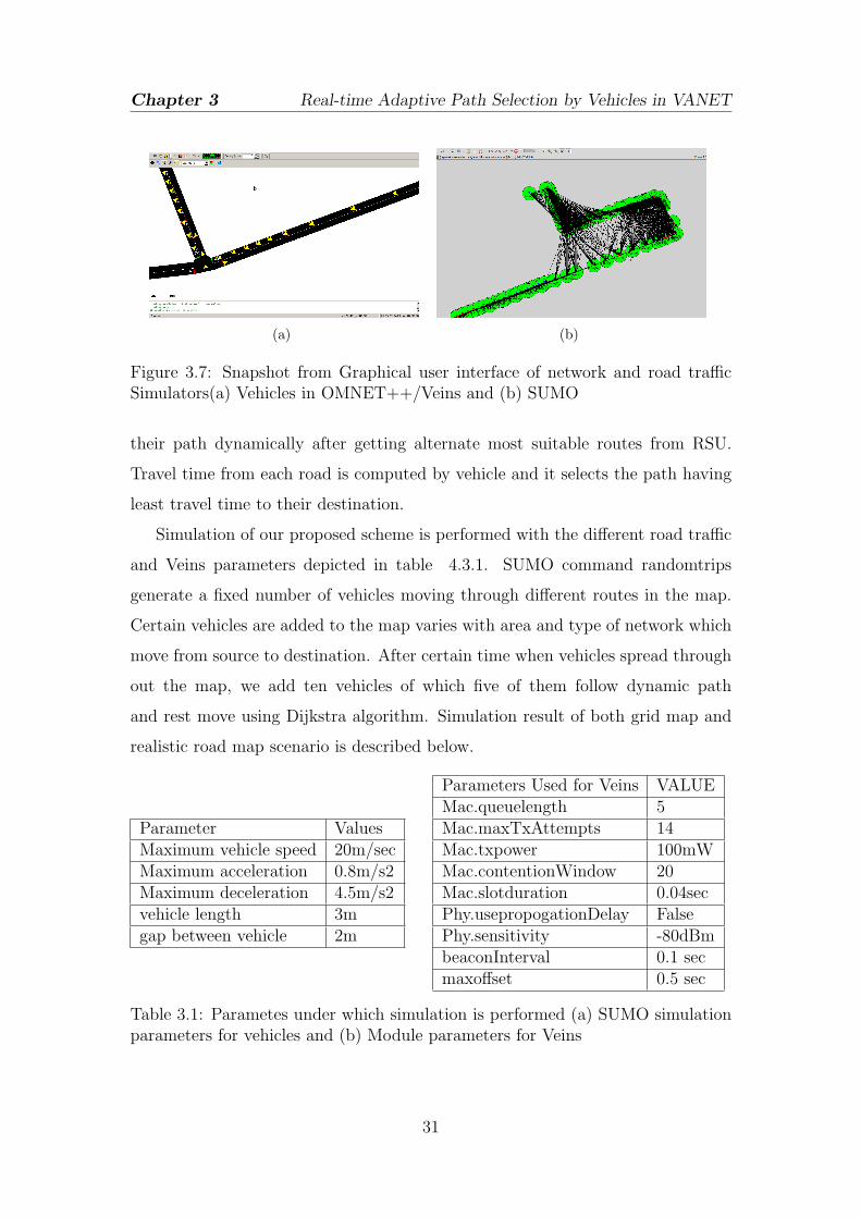
3.7 Snapshot from Graphical user interface of network and road traffic
Simulators(a) Vehicles in OMNET++/Veins and (b) SUMO . . . . 31
3.8 Screenshot of map to which vehicles moves(a) single lane road of 2
x 3 cells on Grid Scenario, and (b) Realistic Road Traffic Map of
NIT Rourkela, India obtained from OpenStreetMap Project . . . . 32
3.9 Results obtained for vehicles route selection following Dynamic path
and Dijkstra Algorithm in Grid Scenario (a) Total time taken and,
(b) CO2 emission based on movement from source to destination
by vehicles . . . . . . . . . . . . . . . . . . . . . . . . . . . . . . . . 33
3.10 Total distance and time taken by vehicles to move from source to
destination in a scenario where fixed large number of vehicles are
moving in network . . . . . . . . . . . . . . . . . . . . . . . . . . . 33
viii
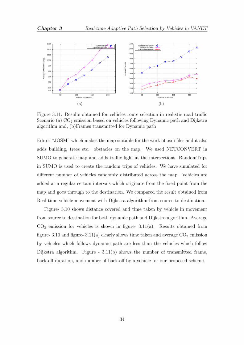
3.11 Results obtained for vehicles route selection in realistic road traffic
Scenario (a) CO2 emission based on vehicles following Dynamic
path and Dijkstra algorithm and, (b)Frames transmitted for
Dynamic path . . . . . . . . . . . . . . . . . . . . . . . . . . . . . . 34
4.1 Creation of new group . . . . . . . . . . . . . . . . . . . . . . . . . 40
4.2 Creation of new group . . . . . . . . . . . . . . . . . . . . . . . . . 42
4.3 Packet format in normal mode . . . . . . . . . . . . . . . . . . . . . 43
4.4 Packet format in safety mode . . . . . . . . . . . . . . . . . . . . . 43
4.5 Packet format in safety mode . . . . . . . . . . . . . . . . . . . . . 43
4.6 VANET basic infrastructure . . . . . . . . . . . . . . . . . . . . . . 46
4.7 Vehicle Authentication by TA . . . . . . . . . . . . . . . . . . . . . 46
4.8 Key transmission from TA to vehicle . . . . . . . . . . . . . . . . . 49
4.9 Secure communication between vehicles . . . . . . . . . . . . . . . . 49
ix

List of Tables
3.1 Parametes under which simulation is performed (a) SUMO
simulation parameters for vehicles and (b) Module parameters for
Veins . . . . . . . . . . . . . . . . . . . . . . . . . . . . . . . . . . . 31
4.1 Notation used for the Algorithm . . . . . . . . . . . . . . . . . . . . 39
4.2 Notification used for this Algorithm . . . . . . . . . . . . . . . . . . 47
4.3 Comparision with different broadcast algorithm . . . . . . . . . . . 50
x

Chapter 1
Introduction
VANET and Group Communication
Problem Definition
Motivation
Objective
Thesis Organization
1

Chapter 1 Introduction
1.1 VANET and Group Communication
Wireless communication has influenced ours lives in many ways by making our
life more convenient, easier and comfortable. VANET is a type of Mobile Ad-hoc
Network in which vehicles move rapidly through the road and topology changes
very frequently. VANET helps to provide safe, secure and more comfort travel to
travelers. Different application of VANET includes Cooperative collision warning,
giving a warning message about steep curve, accidents etc., Congested Road
Notification, Traffic Probe, Parking spot locator etc. i.e. VANET in addition to
safety, security, applications also provide convenient, and infotainment services.
Vehicles uses the Road side infrastructure in different applications which are less
prone to high latencies.
Vehicles information optimization while sharing information to other vehicles is
not an easy task. For example, Vehicles communicate their local edge information
to other vehicles but this information will not be relevant to vehicles moving on
different edge or vehicles moving in opposite directions. It is required to ensure
that information to be delivered at the right place. Data from large number of
vehicles in close geographical region create huge packet having similar/duplicate
information. Since vehicles moving in a close geographical region have similar
mobility pattern and there is a correlation among data so each vehicle need
not require to rebroadcast the data sent from neighbor’s vehicle. To solve the
problem vehicles form a group with other vehicles having a similar mobility
pattern as depicted in figure 1.1. The group contains one Group leader (GL)
which control the group and all other vehicles send the information to it. GL of
the group changes frequently due to high mobility of vehicles or path changes at
intersections. Group can be static or dynamic depending on different conditions.
Many paper has been proposed for group formation with least ID as GL or GL
having maximum neighboring vehicles in the group. We have modified group based
concept depending on different applications. In the first scenario, GL receives the
information of its edge from moving vehicles which it aggregates and summarize.
The summarize information is used by vehicles to select adaptive path with the
2

Chapter 1 Introduction
Figure 1.1: Group Communication among vehicles
help of the RSU. In the second scenario, dynamic group has been created in which
GL collects information within the transmission range of vehicles and it uses group
communication for efficient transmission of event-driven safety message (ESM)
among its members and nearby groups.
1.2 Problem Definition
In our work, it has been given more focus towards the integration of group
communication with different applications. Group communication has been used
previously in the area of VANET. It has been integrated with different areas
e.g. safety and security to solve the different problems efficiently. Previously
work has been done to optimize the group communication by choosing the GL
in different ways and forming Group static and Dynamic. We have optimized
different applications based on group communication. We have used it to optimize
the path selection and event-driven safety message transmission (ESM) by the
vehicles. Vehicles dynamically select optimized path to their destination based
on the traffic congestion. We have added various parameters to ESM protocol
to minimize network packet and make it more reliable. We improved group
communication for ESM message so that it could work both for urban scenario of
the city and the highway.
3

Chapter 1 Introduction
1.3 Motivation
This work has been motivated to the systematic analysis of different applications
of VANET based on networking point of view. Our motive is to use the connection
among different networking based VANET applications and the standard VANET
protocols to create a better traveling. The main goal of our work is to determine
the making the applications of VANET more convenient, safe, secure and efficient
with the help of grouping. Grouping of the vehicle reduces the number of packets
in the network. Simultaneously we ensure not to important data loss in packet
sent from vehicles to GL. Grouping of vehicles with or without the help of V2X
communication works efficiently depending on different application. Vehicles
finding their shortest path route use group formation from every edge where GL
sends the aggregated information to the nearest RSU. In the event driven message
transmission vehicles grouping helps to send data with fast,efficient and safe way.
1.4 Objective
In our work there are two main basic objectives using the Group communication.
(1) Adaptive optimal path selection by vehicles.
(2) An efficient event-driven safety message transmission by vehicles using
VANET.
1.5 Thesis Organization
The organization of the rest of the thesis is as follows. Chapter 2 throws
brief discussion about Vehicular Ad-hoc Network, its different applications,
protocols, and Group communication between vehicles. Chapter 3 describes the
existing work and proposed work in details that includes Real-time adaptive path
selection using grouping of vehicles in VANET. Chapter 4 describes the existing
and proposed work about event-driven safety message transmission protocol for
4

Chapter 1 Introduction
VANET. Experimental results are also included in chapter 3 and chapter 4. The
work presented is summarize in chapter 5.
5

Chapter 2
Background
VANET Introduction
Applications
VANET Protocols and Recent Projects
Main Challenges of VANET
Mobility Models
6

Chapter 2 Background
2.1 VANET Introduction
Communication Technologies have become an essential part of our life to get
different kind of services. Wireless communication in vehicles has fascinated
researchers since the 1980s. In the last few years, there has been increased
large number of research in this area. IEEE 802.11 standard has been setting
the standard for vehicular manufacturer to address the safety and comfort issues
of vehicles. Now a separate wireless spectrum has been allocated for vehicular
wireless communication. With the introduction of Global Positioning system
(GPS) and wireless transceivers in 1990s, further stimulated the research in the
field of inter-vehicular communication. Millions of people across the world die and
even more injured due to vehicles accident in a year. A vehicle collects the safety
and other information and re-distribute to other vehicles with the help of V2V and
V2X communication, as for example the warning message is sent to drivers about
the danger before they actually face it. Most available wireless communication
relies on base station as it helps to synchronization and other services; however
using RSUs covering throughout the road network is very expensive and difficult
to deploy. If VANET is successfully implemented on the road then it will form
the biggest ad hoc network ever implemented, but still stability, reliability and
scalability are a major concern of it. Intelligent Transportation Systems(ITS)
have been stimulated the development of Vehicular Ad-hoc Network (VANETs).
In this type of network vehicles are equipped with equipment through with they
communicate with each other through V2V and V2X communication.
VANET mainly contains following essential entities which are required to
support it:
(1) Vehicles: vehicles are moving node able to communicate in V2V and V2I
mode. Vehicles on-board (OBU) are equipped with GPS device, sensors,
wireless omnidirectional antenna and a digital map of the network.
(2) RSU: RSUs are fixed infrastructural unit placed near to the roadside. RSUs
collect the information from one network and forward the information to
7
Chapter 2 Background
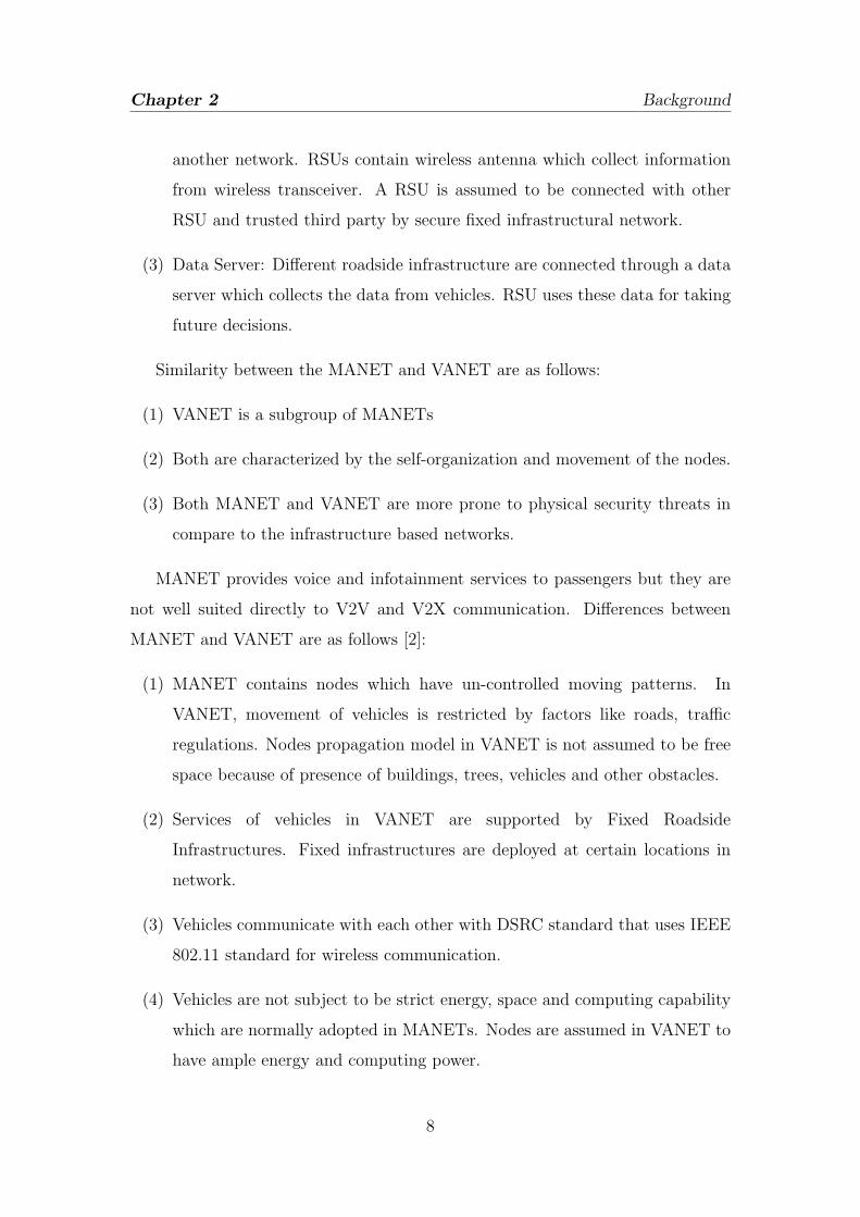
another network. RSUs contain wireless antenna which collect information
from wireless transceiver. A RSU is assumed to be connected with other
RSU and trusted third party by secure fixed infrastructural network.
(3) Data Server: Different roadside infrastructure are connected through a data
server which collects the data from vehicles. RSU uses these data for taking
future decisions.
Similarity between the MANET and VANET are as follows:
(1) VANET is a subgroup of MANETs
(2) Both are characterized by the self-organization and movement of the nodes.
(3) Both MANET and VANET are more prone to physical security threats in
compare to the infrastructure based networks.
MANET provides voice and infotainment services to passengers but they are
not well suited directly to V2V and V2X communication. Differences between
MANET and VANET are as follows [2]:
(1) MANET contains nodes which have un-controlled moving patterns. In
VANET, movement of vehicles is restricted by factors like roads, traffic
regulations. Nodes propagation model in VANET is not assumed to be free
space because of presence of buildings, trees, vehicles and other obstacles.
(2) Services of vehicles in VANET are supported by Fixed Roadside
Infrastructures. Fixed infrastructures are deployed at certain locations in
network.
(3) Vehicles communicate with each other with DSRC standard that uses IEEE
802.11 standard for wireless communication.
(4) Vehicles are not subject to be strict energy, space and computing capability
which are normally adopted in MANETs. Nodes are assumed in VANET to
have ample energy and computing power.
8

Chapter 2 Background
(5) High speed vehicles (up to 250 km/h) and large dimension of the VANET
are more challenging problems.
(6) Due to high speed of nodes, network topology changes very frequently.
Vehicles are moving at the speed of 60-75 kmph(25 m/sec) and if radio
range between two vehicles is 125m then the link between the two vehicles
would last at most 10 sec.
(7) In VANET, frequent disconnection of network occurs due to link between
vehicles changes quickly. This problem is further worsening due to difference
of vehicles density in highway and urban scenarios. Also, vehicles frequency
decrease in non-rush hours causes frequent disconnectivity.
2.2 Applications
Vehicles in VANET with the help of network protocol stack and system integration,
provide different applications. A vehicular generic class of applications most
likely to have a similar set of protocols and mechanisms in the network stack
due to similar application characteristics and performance requirements. Network
designers should be able to maximize the re-usability of common mechanistic
’building modules’ for a specific class of applications with similar application
characteristics and performance requirements. Research on VANET has driven
network support of various application development. Research on deployment of
RSUs are carried out by DSRC research community helping future deployment
in V2X applications to provide safety/warning applications and highway traffic
management for commercial applications. Applications of VANET are roughly
organized into three major categories based on costumers benefit of applications
[3].
It can be categorized and classified the applications based on the application
related characteristics. There are different classification of applications like
the entities participated in the application, the geographical region in which
the application works when the applications will be triggered, end-to-end
9

Chapter 2 Background
communication, the network protocol used, and kind of security used etc. The
message packet format varies with the type of applications. Normal safety
and convenience applications use lightweight short messages while commercial
applications on the other hand, generally prefer the traditional heavyweight IP
format to be compatible with existing commercial Internet services. Application
classification is conducted at various levels, depending on design granularities.
High level classification is helpful to distill the major concepts and identifying the
synergy among various applications [3].
V2V/V2I applications classification based on network design are mainly
divided in two parts:
(1) Short Message Communication: Applications using short message
communication use both broadcast and unicast communication. Broadcast
communication are used for event-driven, scheduled and On-demand
applications while unicast is used for secure and non-secure routing.
(2) Large-Volume Content Download/ Streaming: These applications generally
use unicast communication. It is generally used for file download and video
streaming.
2.3 Protocols and Recent Projects
There has been improvement in Intelligent transport systems (ITS), due to
investment from the government, academia, and industry, leading to the
development of safety and traffic management technologies in vehicle and road
infrastructure. There has been proposed different protocols to meet the standard
to support ITS but recently proposed WAVE standards on the dedicated short
range communications (DSRC) is the only standard that meet the requirement for
road safety messaging and control. But still there are several social and technical
challenges with DSRC protocol to dealt with large scale deployment.
WAVE system supports two classes of devices: on-board unit (OBU) and
roadside unit (RSU). It supports two classes of communication : V2V and V2I.
10

Chapter 2 Background
In the united state , 75 MHz of spectrum in the 5.9 GHz frequency band has
been allocated for DSRC applications. This 75 MHz frequency band is divided
into seven 10 MHz channel and the rest 5 MHz is reserved as the guard band
[4]. In seven channels available spectrum is configured in to one control channel
(CCH) and six service channels (SCHs). The CCH is reserved for high-priority
short message or management data, while others are transmitted on the SCHs as
shown in figure.
The IEEE 1609 family, IEEE802.11p and the society of Automotive Engineers
(SAE) J2735 collectively form the key parts of the WAVE protocol stacks [5]. The
major component of WAVE protocol stack and its associated standards are shown
in figure 3.2.
Figure 2.1: The DSRC Frequency Allocation in US
Figure 2.2: The WAVE Protocol Stack and Its Associated Standards
Important VANET project based on th research related to VANET and ITS
11

Chapter 2 Background
research are as follows [6]:
• CAR 2 CAR Communication Consortium: It is a nonprofit European
organization supported by equipment suppliers, research organizations, and
other partners. Objective of this project is to further increase road traffic
safety, and efficiency by means of cooperative ITS with V2V communication
supported by V2I communication.
• CARLINK Consortium: The aim of this project to develop an intelligent
wireless traffic service platform between cars supported by wireless
transceivers beside the road.
• GeoNet: It uses the basic result of CAR 2 CAR Communication Consortium
and take it the next step. It create a baseline software implementation
interfacing with IPv6.
• iTETRIS: It develops an evaluation platform for large-scale, long-term
simulations of cooperative traffic management applications. It performs
detailed analysis of effects and performance of cooperative applications on
traffic flow, travel time, emissions etc.
• NOW: Network On Wheels NoW is a German research project which
is supported by the Federal Ministry of Education and Research. The
main objectives are to solve technical key questions on the communication
protocols and data security for Car-2-Car Communications.
• SEVECOM: Sevecom is an EU-funded project that focuses on providing
a full definition and implementation of security requirements for vehicular
communications.
2.4 Main Challenges of VANET
The main challenges of VANET are divided in to two categories: Technical
challenges and Socioeconomic challenges [5].
12

Chapter 2 Background
2.4.1 Technical Challenges
First and central challenges of VANET is that no communication coordinator can
be assumed to be possible. In all the area of the network roadside infrastructure
deployment is very difficult. Although some applications are needed infrastructure
like traffic signal violation warning, toll connection and optimal path selection.
Design of the medium access control (MAC) layer is the key issue in the design
of the VANET. Now, the main focus of VANET on using the IEEE 802.11 carrier
sense multiple access (CSMA)- based MAC for VANETs. This is due to availability
and cost considerations and accepts the random elements of such a MAC. The
bandwidth of frequency channel varies in the range of 10 to 20 MHz and with such a
high vehicular density, these channels easily could suffer from channel congestion.
If more than one channel used then it leads to multi-channel synchronization
problem especially in the case of a single transceiver per vehicle and co-channel
interference problems.
Other challenges of VANET are the highly dynamic network topology
due to high speed movement of vehicles and the consequences of it the
environmental impact on their radio propagation. The lower antenna heights and
attenuation/reflection of all the moving vehicles’ metal bodies make the condition
worse. VANET should work in large area, for sparse and dense vehicles traffic
region and should be scalable. Adaptive transmission power and rate control
is strongly needed to achieve a reasonable degree of reliable and low latency
communication.
In VANET, achieving security and privacy is also a major challenge. Receiver
must sure and trust the source of information, privacy requirement of a sender
and, data must be confidential.
2.4.2 Socioeconomic Challenges
Market adoption is also a major challenge. Convincing costumer to purchase the
vehicles equipped with VANET technology is difficult job. If number of vehicles
equipped with VANET technology will be very less on roads then the benefits
13

Chapter 2 Background
of it cannot be achieved. Deploying RSUs is also a costly approach in initial
stages. Still various major issues are yet to solve before deployment like backhaul
connectivity, IT-management issues, road operators etc.
2.5 Mobility Modeling
In VANET, there is a strong interaction between the network protocol and
vehicular mobility. Mobility is influenced by data traffic. There is a need for
simulation study of VANETs for a mobility model reflecting the real behavior of
vehicular traffic. It is required to be dynamically reconfigurable in order to reflect
the effect of communication protocol on vehicular traffic. After several years of
research, now a large number of mobility models are available from most trivial to
realistic ones. But, still it is difficult to select a good mobility model because of
their difficulty in understanding of each model’s characteristics and their benefits
and drawbacks [7].
The mobility model is usually classified in two types as macroscopic or
microscopic. Macroscopic mobility model are helpful to search gross qualities
of interest, such as vehicular density, mean velocity etc. Microscopic modeling
considers each vehicle as a distinct entity, which result the behavior in a more
precise way but computationally more expensive way. The Microscopic modeling
model are helpful in identifying functional block like motion constraints, traffic
generator, and time and external influences. Microscopic simulation model
deals with properties like the inter-vehicular distance, acceleration, breaking,
overtaking. Mobility model intended to generate realistic motion patterns
includes the building block like accurate and realistic topological maps, obstacles,
vehicles characteristics (speed, acceleration, deceleration, speed compatibilities),
trip motion, path motion, smooth deceleration and acceleration, human driving
patterns, time patterns, external influence etc [8].
14

Chapter 3
Real-time Adaptive Path
Selection by Vehicles in VANET
Introduction
Literature survey
Proposed Protocol Model
Results and Discussion
15

Chapter 3 Real-time Adaptive Path Selection by Vehicles in VANET
3.1 Introduction
VANET helps to provide safe, secure and more comfort travel to travelers.
Vehicular Network can be used to reduce travel time by alerting drivers about
potential traffic jams and alternate available routes. India has 142 million
registered vehicles in march 2011. The area occupied by roads and streets in
Class-I cities (population more than 100,000) in India is very less compared to the
United States of America ( India-16.1%, USA-28.19% ) of the total development
area[9] which results in increased traffic accidents and traffic jam at rush hour
in cities. The 2007 Urban Mobility Report stated that traffic congestion causes
4.2 billion hours of extra travel every year in the US, which almost accounts for
2.9 billion extra gallons of gas. Infrastructure growth as compared to increasing
vehicles on the road is not possible due to cost and space constraint. Intelligent
Transportation System (ITS) can mitigate the problem of traffic congestion by
providing the information about road traffic status and, efficient utilization of
transportation resources.
VANET assisted ITS have capability to develop traffic control applications
with collaboration of vehicles with road side infrastructure (RSU). Vehicles are
able to select an alternate path to cop traffic congestion with the help of ITS in
urban areas of a city. Vehicles can use Dijkstra algorithm to calculate shortest
paths with the help of city map but this selected shortest path is usually not be
a shortest time path in an urban scenario. Vehicles need to travel path having
shortest time to reach their destination in place of the shortest distance path to
avoid traffic congestion. The optimal path selection by vehicles also reduces the
amount of CO2 gas emitted by vehicles, fuel consumption, travel cost, and travel
time and improve the spatial utilization of road network.
The main objective of our proposed scheme is to design an algorithm for
real-time adaptive path selection by vehicles. The goal of this study is twofold:
(i) We intend to minimize the travel time of vehicles.
(ii) Vehicles avoid creating congestion by selecting real-time non-congested path
16

Chapter 3 Real-time Adaptive Path Selection by Vehicles in VANET
in their route.
In this section, we propose a real-time dynamic path selection protocol by vehicles
with the help of the RSU. RSU aggregate the information of network which is
used by vehicles to select their path. We have optimized the data dissemination
in network about current traffic details by using Group communication between
vehicles. GL is selected from each group which communicates with RSU through
multi-hop broadcast communication. Additional parameters have been considered
like the addition of value added services, maximum allowable speed limit on
a road, obstacles on a particular road like traffic signals, accidents to further
improve path selection by vehicles. RSU sends message to vehicles if found route
congestion in vehicles path. Finally, we have simulated to our scheme to evaluate
the effectiveness and efficiency of proposed protocol. Simulation of the proposed
Scheme confirms that vehicle chooses the alternative path according to the set of
rules of proposed scheme when they find congestion on the current route. We have
considered both grid-network map and real-scenario map simulation environment
in which random number of vehicles are generated which moves at various road
segments to create road congestion. We have taken various parameters as discussed
above to simulate the scenario. Simulation is performed by using OMNET++
which is free network simulator for academic use, microscopic traffic simulator
SUMO to handle road traffic mobility and Veins.
Figure 3.1: V2V/V2I communicationFigure 3.2: RSU distribution inVANET Network
17

Chapter 3 Real-time Adaptive Path Selection by Vehicles in VANET
3.2 Literature survey
Lin et al. proposed in [10] to select path by vehicles from an origin point to
a destination point such that total wireless connection- capacity is maximized
keeping minimum driving distance. Verroios et al. [1] proposed dynamic path
selection by the vehicle based on estimations received from fellow travelers.
It presented a distributed protocol that allows for vehicles to exploit selective
information obtained from others traveling ahead in a trajectory towards a
destination. Dobre et al. proposed in [11] a system by using additional sensors
within the roadside infrastructure. It has considered only the speed of vehicles
on a particular lane to avoid traffic congestion. Vehicles moving ahead exchange
information that allows route selection of vehicles moving behind it. Bai et al. [?
] proposed indexing method which uses view-based hierarchy search method for
optimal path detection. Eggenkamp et al. [12] used extended Dijkstra Algorithm
to find optimal path. Lam et al. [13] presented a system by dividing the area in
to cells and in each cells it caches the data item of the database. Vehicle traffic
information in decentralized structure is proposed in [14, 15, 16, 17] based on
inter-vehicular communication.
We cannot aggregate the full network simultaneously to evaluate the network
details, so group formation is required to aggregate the local details. Several
Groups/ Cluster based Algorithm has been proposed in recent years to reduce
the packet transmission in the Network. Caballero-Gil et al. [18] proposed
algorithm to reduce communication overhead in VANETs. Paridel et al.[19]
proposed context-based grouping for efficient collaboration in VANETs. Ohta
et al. [20] presented clustering-based data transfer scheme using positions and
moving direction of Vehicles for VANETs. Luo et al. [21] designed a new routing
protocol for VANET, based on cluster-based routing. Song et al. [22] proposed a
cluster-based directional routing protocol in VANET.
18

Chapter 3 Real-time Adaptive Path Selection by Vehicles in VANET
3.3 Proposed Protocol Model
3.3.1 VANET Architecture
In VANET, Vehicles communicate with other vehicles (V2V communication) and
with Road Side Infrastructure (V2I communication) as depicted in figure-3.1. RSU
exchange traffic information to moving vehicles, which uses by drivers to adjust
their routes to avoid congestion. The entire network is divided into segments by
RSUs which collects information on a particular area as depicted in the figure- 3.2.
Distribution of area by RSU helps to decentralize processing of the traffic data,
and prevent spreading of irrelevant data.
The road network is considered as an undirected graph with road junction
as a node and road as a segment of an edge between two consecutive junctions.
Vehicles move to the different edge and change their path at the node of the graph.
Vehicles take the help of GPS device to know about the current edge and distance
of nodes. The vehicle PDA device takes input data from a GPS device and stores
it as a directed graph. Figure-3.3(b) shows the sub graph of their corresponding
road network Figure- 3.3(a).
(a) (b)
Figure 3.3: PDA obtains data from GPS device and stores it as a directed graph[1] (a) A road network and,(b) Corresponding directed graph
3.3.2 Assumptions
We have considered transmission range are same for vehicles, GL and RSU.
Mobility of vehicles possesses some constraints to provide safety and security
19

Chapter 3 Real-time Adaptive Path Selection by Vehicles in VANET
applications. Vehicles move with constant speed and maintain a definite gap
between each other to prevent accidents. Vehicle movement also depends on the
vehicles moving ahead of it. Vehicles maintain their lane and obey traffic signals
during movement. RSUs are placed near to the different roadside at intersections.
3.3.3 Network Model
RSU exchange traffic information with moving vehicles, which allows Drivers to
change their route to avoid congestion. RSUs are placed at different intersections
which monitor the data sent from vehicles. Different RSUs helps to decentralize
processing of data, and prevent spreading of irrelevant data. Urban area of a city
consists large number of vehicles in close proximity. If each vehicle sends data to
each other then it will create huge network congestions.
To reduce network congestion modified group concept is used for vehicles.
Vehicles moving on a single edge segment form one group. A GL is selected
from each group which receives the information of vehicle speed, queue length
and position received from vehicles in the group about the road segment. GL
aggregates the speed of vehicles. GL finds the nearest RSU from the geographical
location of RSU from digital map obtained by GPS device and transmit the
gathered data to RSU.
We have considered a case in which GL ’x’ is near by two RSUs, A and B as
shown in figure- 4.7. Let the geographic location of GL ’x’ is (x, y) and that of
RSU ’A’ and RSU ’B’ are (x1, y1) and (x2,y2) respectively. Vehicle ’x’ measures the
distances and direction of flow from RSU ’A’ and RSU ’B’. R1 and R2 are distances
from RSU ’A’ and RSU ’B’ respectively. It follows algorithm- 1 to decide whether
to send data to RSU ’A’ or RSU ’B’.
The group consists of a set of vehicles moving in a close geographical area nearly
having same mobility patterns. Each group chooses a GL among its members who
can communicate with its own Group members, summarizes the information about
the Group and communicate with the RSU. Group reduces information exchange
between vehicles and RSU. In the absence of the group, each vehicle broadcasts its
20

Chapter 3 Real-time Adaptive Path Selection by Vehicles in VANET
Figure 3.4: Measurement of nearest RSU by vehicles
R1 =√
(x− x1)2 + (y − y1)2
R2 =√
(x− x2)2 + (y − y2)2
α1 =Angle of direction of vehicle and RSU ’A’ with vehicle’s flow of directionα2 = Angle of direction of vehicle and RSU ’B’ with the vehicle’s flow ofdirectionif α1 ≤ α2 thenVehicle is heading towards the direction of RSU ’A’
elseVehicle is heading towards the direction of RSU ’A’
end ifif vehicle is heading towards the direction of Ra thenif (R1-R2) ≥ 0 thenSend message to Ra.
elseif (R1 - R2) ≤ 0 and R1 ≤ 3(R1+R2)
4then
Send message to Ra
elseSend message to Rb
end ifend if
elseSend message to Rb
end ifAlgorithm 1: Selection of RSU by vehicles
information and uses multi-hop communication to send its information to RSU. It
creates a large number of duplicate packets or packet having similar information
as vehicles moving near-by location have correlation about speed, acceleration etc.
Consequences of it, packet dropping is increased due to collisions and it reduce
the network throughput.
21
Chapter 3 Real-time Adaptive Path Selection by Vehicles in VANET
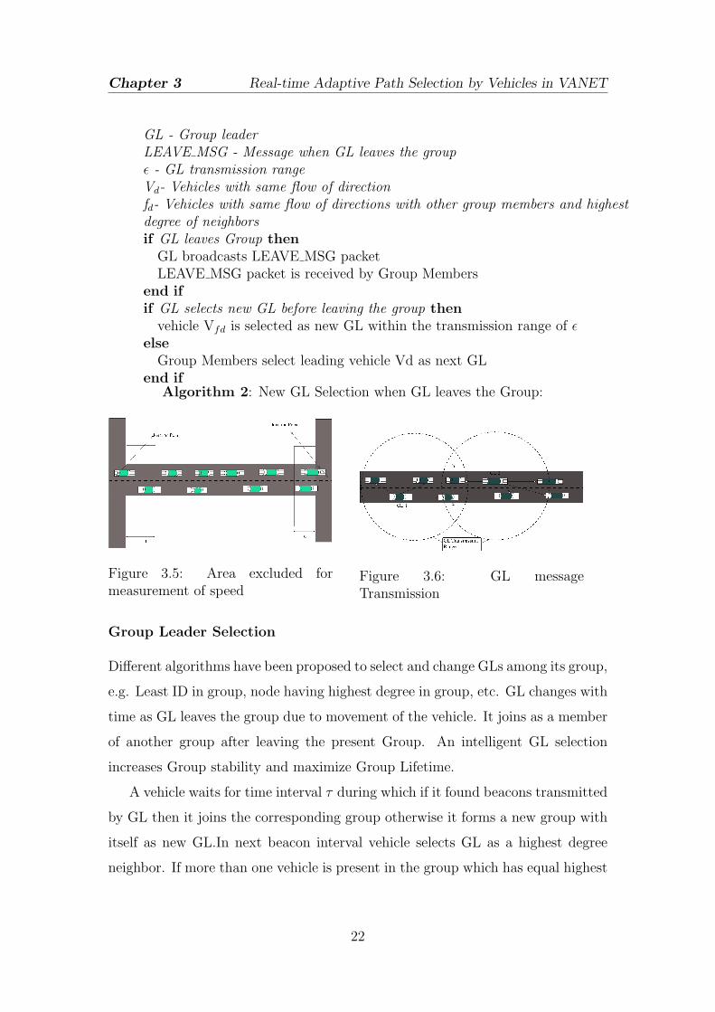
GL - Group leaderLEAVE MSG - Message when GL leaves the groupε - GL transmission rangeVd- Vehicles with same flow of directionfd- Vehicles with same flow of directions with other group members and highestdegree of neighborsif GL leaves Group thenGL broadcasts LEAVE MSG packetLEAVE MSG packet is received by Group Members
end ifif GL selects new GL before leaving the group thenvehicle Vfd is selected as new GL within the transmission range of ε
elseGroup Members select leading vehicle Vd as next GL
end ifAlgorithm 2: New GL Selection when GL leaves the Group:
Figure 3.5: Area excluded formeasurement of speed
Figure 3.6: GL messageTransmission
Group Leader Selection
Different algorithms have been proposed to select and change GLs among its group,
e.g. Least ID in group, node having highest degree in group, etc. GL changes with
time as GL leaves the group due to movement of the vehicle. It joins as a member
of another group after leaving the present Group. An intelligent GL selection
increases Group stability and maximize Group Lifetime.
A vehicle waits for time interval τ during which if it found beacons transmitted
by GL then it joins the corresponding group otherwise it forms a new group with
itself as new GL.In next beacon interval vehicle selects GL as a highest degree
neighbor. If more than one vehicle is present in the group which has equal highest
22

Chapter 3 Real-time Adaptive Path Selection by Vehicles in VANET
GL - Group leaderτ - Time Interval after vehicle transmit Beaconsε - GL transmission rangeχ - Information received by vehicles from the same road segmentttl=0repeatif GL is in the transmission range of sender vehicle thenGL receives the beacons transmitted by vehicle at every time interval τ .
elsettl=ttl+1Vehicle selects the next hop vehicle in the communication range of it inthe direction of GL.
end ifuntil Vehicle is in transmission range of ε and ttl¡3t=0repeatif χ == true thenAccept the packet and aggregate the information with the informationreceived from other vehicles.
elseDrop the packet.
end ifuntil t ≤ τif t == τ then1. GL sends the aggregated information to RSU through one hop ormulti-hop communication.2. RSU receives the packet and stores it in the data server.t=0
end ifAlgorithm 3: Group Communication by Vehicles:
degree neighbors then vehicle select new GL which is nearer to the middle of the
Group.If GL leaves the group then the process for new GL selection is depicted in
algorithm- 2.
Group Communication
Vehicles periodically broadcast their information in the form of beacons about a
position which contains information about current speed, acceleration, edge id,
lane number, geographical position i.e. vehicles’s latitude and longitude. Routing
of this information is performed by vehicle only through the same road segment
23

Chapter 3 Real-time Adaptive Path Selection by Vehicles in VANET
as of GL. Intra road segment routing is performed with the help of RSU through
which it collects information from one road segment. This information is used by
vehicles moving on other road segments in the network. It also helps to prevent
huge packet routing in the network. Vehicle forwards the packet to GL depicted
in figure- 3.6 by using the Algorithm- 3. If road segment size is larger than the GL
transmission range then vehicle selects an intermediate vehicle in the direction of
GL to which vehicles send its information.
Vehicles move slowly or stop at the junction point due to traffic light. vehicle’s
speed is not considered in range of ’d’ from the junction point for calculation of
average speed of the edge as depicted in figure- 4.2.
d =u2
2a+ average queue length (3.1)
Where, u = speed of vehicle to which it starts deceleration. a = the declaration
of vehicle.
3.3.4 Route Selection Algorithm
RSU is deployed at some important and busier route intersection where the
route selection of vehicles is important and significantly affects the travel time
of the vehicle. RSU performs periodically one-hop broadcast about the current
neighbors’ route traffic information which receives by vehicles nearby intersection.
When the vehicle reaches in the transmission range of RSU it requests route inquiry
to RSU by sending current location, road id, destination road id and optional value
added information, which in reply RSU sends back the current optimized route
for destination. The value added information contain the query about location of
the parking lot, petrol pump, restaurant etc. in the area, which the vehicles want
to avail this services in passing by the routes through the destination. Nearest
RSU receives the data sent from vehicles, collect and aggregate the relevant data
from data server and sent back to the vehicle about optimized route information
to vehicles. Whenever vehicles enter in to RSU region, RSU detects the vehicle
24

Chapter 3 Real-time Adaptive Path Selection by Vehicles in VANET
through its periodic broadcast of beacon information. If the vehicle has already
registered it route details then it finds out from the data stored in the server
whether vehicle following the route is congestion free and shortest time route
or not. If the alternate shortest route is available then RSU sends the warning
message to the vehicle to change its route.
Two types of messages are transmitted by RSU for route selection:
1. RSU periodically broadcasts the local information: RSU periodically
broadcasts the aggregated local information receives from GL in the form
of beacons. The local information contains the information about paths
having congestion. Vehicles receive the path information and change its
routes accordingly.
2. RSU reply vehicle’s request about route selection: Vehicle within its
transmission range of RSU near to the intersection sends request to the
RSU which contains information about destination and additional services
that it requires during their most optimal path searches.
RSUs use the aggregated information stored in data server that has obtained
from vehicle’s GL to find the optimal time path. The optimal path calculated by
RSU is used by vehicles to dynamically determine the path it will follow. Vehicle
in the network is able to cope with traffic congestion in an urban environment by
selecting an alternative route to their destination. It also helps to remove traffic
congestion and ensure proper utilization of roads in the network. The output of
the Algorithm discussed in next section is to find out the average time required
by vehicles to traverse by each route and the average time is used to calculate the
optimal time route for vehicles.
Time Taken to cover the distance of each alternate path
RSUs placed at the junction point measures the distance of each alternate path
from vehicles current edge to the destination edge.RSU gets the length of each
traversing lanes and their average speed sent from their GL, stored on the data
25

Chapter 3 Real-time Adaptive Path Selection by Vehicles in VANET
server. Vehicles are moving on different path having different speed.It measures
the time taken by vehicles from each edge and sums it to find the total time taken
by it in the entire route. E.g. vehicle is assumed to be passing through three edges
having a length d1, d2, d3 and their respective speed on those edges are v1, v2, v3
respectively. Total time taken by vehicle is Ttotal. Where,
Ttotal =d1v1
+d2v2
+d3v3
(3.2)
Time taken due to the addition of value added services
When vehicles have to travel from source to the destination by covering the
particular edge containing a restaurant, petrol pump, parking area etc. then
RSU measures the total time taken by vehicle throughout the journey by dividing
into two parts. In the first part, it measures the total time taken up to the edge
where the vehicle avails the services and in the second part it measures the total
time from particular edge to destination. RSU considers the edge where vehicle
gets the service as a first destination. In this case Ttotal is calculated as follows.
Ttotal = Ttotal1 + Ttotal2 (3.3)
Where,
Ttotal1= Time taken by vehicle from current edge to edge where it avails
services.
Ttotal2= Time from edge where it gets serviced to destination edge.
We have not considered time elapsed to avail the services.
Time taken due to Traffic Light in Path
The number of traffic lights in path add the delay in the path traversed by vehicles
to reach their destination. RSU counts the number of traffic lights and gets the
stop time due to red signal for each traffic light in the vehicle route. Let, Ttf1,
Ttf2, Ttf3 be assumed as delay occurred due to three different traffic lights. A
26

Chapter 3 Real-time Adaptive Path Selection by Vehicles in VANET
total time delay occurs due to traffic light is Ttf . Where,
Ttf = Ttf1 + Ttf2 + Ttf3 (3.4)
Vehicles add the time delay occurs due to traffic light. Traffic signals increases the
path travel time as vehicles have to stop at red signals. Improper traffic light time
at junctions also increases the queue length at junctions. To remove this problem
we have used coordinated traffic light at different junctions. We have considered
special case for emergency vehicles, when it enters into new edge, the traffic light
turns green in the direction of movement of it to avoid queues and waiting time
for a traffic signal. But it increases the waiting time for other vehicle coming from
other directions.
Time taken due to queue in the path of vehicles
Vehicles arrive at the junction point; make a queue and waits for a traffic light
to be green. Vehicles also make queue due to accident or abnormal stop in the
path of a vehicle. Waiting time for vehicle at junction point is the time duration
between the time of arrival and time at which traffic light turns green. GLs send
the information about the queue length occurred at every edge in each route which
is updated at each beacon interval. GL uses this information to calculate the time
delay occurred due to queue. A Vehicle which is in the queue gets service on first
come and first serve basis. We have assumed a point where there are ’n’ numbers
of vehicle in the queue then time consumed by the vehicle is in the queue is the
time taken by each vehicle to reach their maximum speed from rest plus waiting
time due to red light. If we consider a case in which vehicle reaches at queue end
point of length ’q’ with maximum speed ’v’ and if the queue is not present there
then the time taken by vehicle to reach at junction point is Tn. Where,
Tn =q
v(3.5)
27
Chapter 3 Real-time Adaptive Path Selection by Vehicles in VANET
In second case, if queue is present and vehicle stops due to queue at a distance of
q from the junction point then number of vehicle in the queue from junction to
vehicle is (say) N.
N =q
x+ y(3.6)
Where, x= Length of vehicle
y= Distance between each vehicle.
z= Safe distance from junction point.
It has been taken assumption that the length of every vehicle is same and it stops
at equal distances with each other.Time delay by vehicle to reach at a junction
point from the queue endpoint depends on the number of vehicles ahead of it.
The distance of the first vehicle from junction point is by then the time taken by
vehicle to reach to the junction point is T. Where,
T =
√2z
a(3.7)
When the vehicle starts at queue point, its initial speed is zero. It reaches with
maximum speed with acceleration ’a’. Time taken by rest (n-1) vehicle to reach
their junction point is T.
T1 =
√2((n− 1)(x+ y) + z)
a(3.8)
We get total time consumed by a vehicle from the queue end point to junction
point is (say)
T2 = T + T1 (3.9)
Total time delay by vehicle to reach the junction point due to queue is Td. Where,
Td = Tn − T2 (3.10)
From Little Theorem mean queue length is determined as, N=λ T. Where,
λ = Average Costumer Arrival Rate
28

Chapter 3 Real-time Adaptive Path Selection by Vehicles in VANET
T = Average Service time of a costumer.
The queue at a junction point depends on the arrival rate and service rate. We
have calculated the service rate T2 for each vehicle at the junction point. Vehicles
queue service rate depends on the vehicle’s speed, and number of vehicles waiting
ahead in the queue. Vehicles arrival rate is a Poisson process as the number of
vehicles moving on the road in urban scenario is very high so a vehicle is considered
as very small in road resources, and decision taken by vehicle to enter a particular
road is totally dynamically taken by Driver. We have calculated vehicles arrival
rate as the difference of the vehicle entering to the lane to the vehicle leaving the
lane.
Total time taken by vehicle from source to destination depends on the current
average speed of each road, the number of traffic signals crossed, the maximum
allowable path of a road and, the queue length of the selected path. RSU get
the above information from vehicle’s GL and through the GPS device at junction
point and calculate the average time taken through each path segment.
Ttravel = Ttotal + Ttf + Td (3.11)
Vehicle selects the path dynamically with minimum average time Ttravel. At each
junction point containing RSU, vehicles get updated values and vehicle’s PDA
device updates its route information.
Other parameters which are used by vehicles to select an alternate route as
follows.
1. Vehicles prefer to select the main link way to reach their destination. If two
ways take the comparable time then vehicles select the main linking path
between source and destination.
2. Vehicle considers the maximum supportable speed on the road to reach their
destination. If the route contain residential area and schools then vehicle’s
speed on that path is very less and vehicle avoid to that path in the dynamic
selection of paths.
29

Chapter 3 Real-time Adaptive Path Selection by Vehicles in VANET
3.4 Results and Discussion
We have used OMNET++ for network simulation, SUMO for microscopic road
traffic simulation and Veins (Vehicles in Network Simulation) for the coupled
simulation framework which integrates OMNET++ and SUMO. The major
advancement of using Veins is that it is able to generate the real time interaction
between network simulation module and road traffic simulation module. It is
also able to affect road traffic simulation module based on the network simulation
module.
OMNET++ [23] is a discrete event simulation framework which is suitable
for modeling wireless vehicular network. Vehicles communicate with each other
through message passing. OMNET++ supports are limited to simple mobility
patterns like a random way-point model. Since VANET simulation requires
road traffic which mobility pattern is much different from the mobility pattern
supported by OMNET++ so it is used microscopic road traffic simulation tools
SUMO [24].
Mobility of the vehicles is modeled according to trace file generated from real
world scenarios. SUMO provides the microscopic model for traffic simulation
which is required for accurate traffic modeling for each vehicular activity and
interaction like position, speed, and radio transmission between nodes etc.
OMNET++ sends command to SUMO to control road traffic simulation and
SUMO returns the position and other information about the map and traffic
mobility to OMNET++. OMNET++ and SUMO are integrated with the traffic
control interface, TraCI which provides TCP connection between each other [8].
Figure- 3.7(a) and Figure- 3.7(b) shows the vehicles movement in SUMO and Veins
framework respectively.
We have simulated our proposed work in both grid topology and real street
map of the NIT Rourkela, India with the help of Veins. We have extended Veins
command to support our proposed work. In both the scenarios we have compared
cost metric of our proposed work with Dijkstra shortest path Algorithm and vehicle
moving randomly from source to destination. Vehicles moving on the road adjust
30
Chapter 3 Real-time Adaptive Path Selection by Vehicles in VANET
(a) (b)
Figure 3.7: Snapshot from Graphical user interface of network and road trafficSimulators(a) Vehicles in OMNET++/Veins and (b) SUMO
their path dynamically after getting alternate most suitable routes from RSU.
Travel time from each road is computed by vehicle and it selects the path having
least travel time to their destination.
Simulation of our proposed scheme is performed with the different road traffic
and Veins parameters depicted in table 4.3.1. SUMO command randomtrips
generate a fixed number of vehicles moving through different routes in the map.
Certain vehicles are added to the map varies with area and type of network which
move from source to destination. After certain time when vehicles spread through
out the map, we add ten vehicles of which five of them follow dynamic path
and rest move using Dijkstra algorithm. Simulation result of both grid map and
realistic road map scenario is described below.
Parameter ValuesMaximum vehicle speed 20m/secMaximum acceleration 0.8m/s2Maximum deceleration 4.5m/s2vehicle length 3mgap between vehicle 2m
Parameters Used for Veins VALUEMac.queuelength 5Mac.maxTxAttempts 14Mac.txpower 100mWMac.contentionWindow 20Mac.slotduration 0.04secPhy.usepropogationDelay FalsePhy.sensitivity -80dBmbeaconInterval 0.1 secmaxoffset 0.5 sec
Table 3.1: Parametes under which simulation is performed (a) SUMO simulationparameters for vehicles and (b) Module parameters for Veins
31

Chapter 3 Real-time Adaptive Path Selection by Vehicles in VANET
(a) (b)
Figure 3.8: Screenshot of map to which vehicles moves(a) single lane road of 2 x 3cells on Grid Scenario, and (b) Realistic Road Traffic Map of NIT Rourkela, Indiaobtained from OpenStreetMap Project
3.4.1 Grid map Scenario
To evaluate our results we used a simple Grid scenario of 2 x 3 roads which contain
single lane road which are spaced 500 m apart in horizontal direction and 400 m
in the vertical direction as shown in Figure- 3.8(a). A a random trip of vehicle is
generated (20 - 150 vehicles) throughout the map using SUMO command. At the
different time stamp of simulation we added the vehicle on the map which enters
at bottom left corner of the map as the source and destination is set as top right
corner. The traffic light is placed at each intersection. As shown in figure- 3.9(a),
when the least number of vehicles is present in the network then average time
taken by vehicle is same with vehicles which cover path due to no congestion in
network, and vehicle selects shortest route from source to destination. Vehicles
have to cover the longer path when vehicles in the network increases which also
increase the travel time. Figure- 3.9(b) shows the average CO2 emission by vehicle
in moving from source to the destination.
Traffic light obstructions for the entire map are kept as constant i.e. changes at
regular interval of 90 sec except for emergency vehicle. When an emergency vehicle
enters into the lane traffic light turns green irrespective for its time interval. We
manually created traffic jam by stopping of vehicles or creating accident in the lane.
If the vehicle gets no traffic congestion in shorter route than it chooses the shortest
32

Chapter 3 Real-time Adaptive Path Selection by Vehicles in VANET
route from source to destination. The result is obtained after vehicle performs inter
vehicle communication and with communication with fixed infrastructure.
200
300
400
500
600
700
800
900
1000
20 40 60 80 100 120 140
Ave
rage
Tim
e(se
c)
Number of vehicles
Dynamic PathPath with Dijkstra Algorithm
(a)
300
400
500
600
700
800
900
1000
1100
1200
20 40 60 80 100 120 140
Ave
rage
CO
2 em
mis
ion(
g)
Number of Vehicles
Dynamic PathPath with Dijkstra Algorithm
(b)
Figure 3.9: Results obtained for vehicles route selection following Dynamic pathand Dijkstra Algorithm in Grid Scenario (a) Total time taken and, (b) CO2
emission based on movement from source to destination by vehicles
3.4.2 Realistic Road Traffic- NIT Rourkela Street Map
50100
150200
250300 1500 1600 1700 1800 1900 2000 2100 2200 2300 2400 2500
total Distance
Number of Vehicles
Adaptive movementDijkstra Algorithm
Figure 3.10: Total distance and time taken by vehicles to move from sourceto destination in a scenario where fixed large number of vehicles are moving innetwork
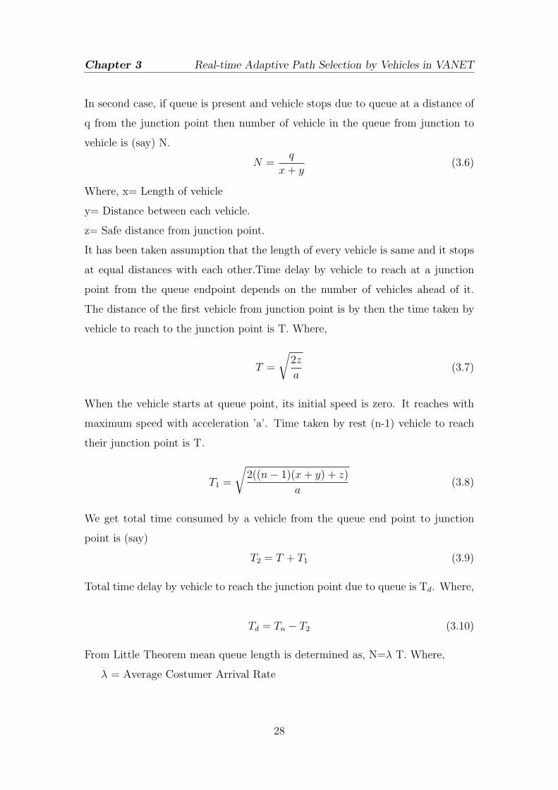
We also simulated our proposed work on a real street map of NIT
Rourkela(Figure- 3.8(b). Road layout of NIT Rourkela is publicly available from
the OpenStreetMap project. The data obtained from the OpenStreetMap are not
suitable for processing in SUMO so map is modified through Java OpenStreetMap
33
Chapter 3 Real-time Adaptive Path Selection by Vehicles in VANET
450
500
600
700
800
900
1000
1100
1200
1300
50 100 150 200
Ave
rage
CO
2 em
mis
ion(
g)
Number of Vehicles
Dynamic PathDijkstra Algorithm
(a)
100
200
300
400
500
600
700
800
900
1000
1100
50 100 150 200
netw
ork
Pac
kets
Number of vehicles
Number of BackoffBackoff Duration
Transmitted Frame
(b)
Figure 3.11: Results obtained for vehicles route selection in realistic road trafficScenario (a) CO2 emission based on vehicles following Dynamic path and Dijkstraalgorithm and, (b)Frames transmitted for Dynamic path
Editor “JOSM” which makes the map suitable for the work of osm files and it also
adds building, trees etc. obstacles on the map. We used NETCONVERT in
SUMO to generate map and adds traffic light at the intersections. RandomTrips
in SUMO is used to create the random trips of vehicles. We have simulated for
different number of vehicles randomly distributed across the map. Vehicles are
added at a regular certain intervals which originate from the fixed point from the
map and goes through to the destination. We compared the result obtained from
Real-time vehicle movement with Dijkstra algorithm from source to destination.
Figure- 3.10 shows distance covered and time taken by vehicle in movement
from source to destination for both dynamic path and Dijkstra algorithm. Average
CO2 emission for vehicles is shown in figure- 3.11(a). Results obtained from
figure- 3.10 and figure- 3.11(a) clearly shows time taken and average CO2 emission
by vehicles which follows dynamic path are less than the vehicles which follow
Dijkstra algorithm. Figure - 3.11(b) shows the number of transmitted frame,
back-off duration, and number of back-off by a vehicle for our proposed scheme.
34

Chapter 4
An Efficient Safety Message
Transmission Protocol for
VANET
Introduction
literature survey
Proposed protocol model : ESM Message Transmission
Security for ESM message transmission
Simulation and Results
35

Chapter 4 An Efficient Safety Message Transmission Protocol for VANET
4.1 Introduction
In VANET, vehicles broadcast beacons periodically which contain vehicles
common characteristics like position, velocity and lane number. Receiver Vehicle
uses this beacon information to predict the movement of sender vehicles. Vehicles
trigger event safety messages when any abnormal changes occurs in vehicles
behavior which breaks the normal continuity of movement of vehicles such as
hard braking, sudden lane change, break failure, engine breakdown or any other
vehicle malfunction. If any such incidents occur, abnormal vehicle sends ESM
to all endangered vehicles to prevent collisions. These messages must reach to
endangered vehicles in real time. The main objective our proposed scheme is to
design an efficient and reliable routing algorithm. Goal of this study is of twofold:
1 We intend to minimize the network congestion by reducing participating
vehicles in information transmission. Large number of vehicles is present in
close proximity create huge network congestion.
2 Use of Context-based grouping.
We propose a Group based communication mechanism to optimize ESM
information transmission. Vehicles form groups and select a Group Leader (GL)
within its transmission range. GL summarizes the information and broadcast
it within the group and to the next GL. We have also considered impact of
velocity of nodes during the transmission of ESM packets because as vehicles
speed increases or decreases, frequent link disruption occurs. We have used
context-aware inter-group transmission of packets to reduce network congestion.
The main objective of context-aware grouping is that only relevant vehicles will
receive packets which are affected by accidents. We have simulated the scenario by
using network simulator and road traffic simulator. We have used OMNET++,a
free network simulator for academic use. It helps to model realistic communication
between vehicles. For traffic simulation we have used microscopic road simulator
sumo.
36
Chapter 4 An Efficient Safety Message Transmission Protocol for VANET
Trust is an essential requirement of VANETs when one vehicle sends ESM
message to another. ESM messages have highest priority so a user will feel
comfortable only when he can trust the ESM messages he receives. A VANET
becomes trustworthy when all the vehicles within it are trustworthy. Only in this
condition, user can believe on network components. If an adversary deliberately
broadcast false ESM message, or send old or expired information (Replay Attack)
then this information can misdirection the road traffic and it will become major
cause of impairment in traffic safety.
If RSUs are not protected, deployed near to roadside, without any physical
protection then it can easily compromised. RSU is also under attack by adversary
for sending false, modified, expired or misleading information that may cause
dangerous consequences to OBU. In grouping, an untrusted vehicles within the
group may also sends false information.
To overcome the above discussed risk factor, it is compulsory to verify the
identity of message sender, as well as maintaining integrity of the message. This
can be achieved through suitable secure protocol. Identity verification is a tough
task in VANET due to high and variable velocity of nodes, variable node density
and also it operate on roads with nonuniform characteristics. Its also a problem
for a single controller which can not handle thousands of vehicles at a time.
It is important to limit the wireless traffic intensity to avoid packet collisions
at the Medium Access Layer (MAC) layer. Increased collision rate impair the
performance of vehicular communication. Since, WAVE standard can not handle
with many high priority messages in a dense network scenario. We are needed a
trust scheme that has low computational complexity, high scalability, as well as
reliable and quick verification mechanism.
4.2 Literature survey
Protocol applied in MANET cannot be directly implemented on VANET due to
high mobility. We cannot aggregate the full network simultaneously to evaluate
the network details, so we require group formation to aggregate the local details.
37

Chapter 4 An Efficient Safety Message Transmission Protocol for VANET
Bo Xing et al. [25] discussed the problem of varying reliability needs and fast
broadcast of critical data over Ad-hoc networks. Guan et al. [26] proposed two
algorithms for low priority safety messages to improve channel utilization and
channel availability for high priority emergency messages. Suriyapaiboonwattana
et al. [27] proposed an adaptive alert message dissemination protocol for VANET
to improve road safety. Ma et al. [28] proposed and justified the design for
control channel in DSRC for vehicle-safety-related applications. Peksen et al. [29]
proposed multi-hop safety message broadcasting in VANET by relying metrics.
Various papers [30], [31], [32] have been proposed on different issues of Safety
Related Messages.
Paper [33] create the group offline and each group messages includes with it an
authentic group ID .It generate a group signature on each of its message. Vehicle
in the group can send data only inside the group. Group Managers (GMs) have
the responsibility to admit new vehicles and to evict attacker/malicious vehicles.
Paper [34] proposed the model for trusted grouping using TPM Hardware. It
provide hybrid cryptography scheme. The IEEE 1609.2 industrial standard as
well as most of the earlier works in the literature [35], [36] propose the use of
digital signatures (such as ECDSA and NTRU) and public-key infrastructures
(PKI) in the provision of message authentication services. To ensure user
privacy, each vehicle is preloaded with a large set of short-lived pseudonym
certificates used for message signing at the expense of storage. As opposed to
these works which rely solely on PKC, we use much more efficient symmetric-key
techniques for data communication. For instance, the TESLA protocol [37]
uses symmetric-key techniques for broadcast authentication and relies on time
to create the asymmetric knowledge between the sender and the recipient. Studer
et al. [38] observed that TESLA is subject to memory-based DoS attacks
against the recipient in VANET settings due to the storage of previously received
messages. Therefore, they proposed TESLA++, a modified version of TESLA,
which requires the recipient to store a self-generated MAC of the message’s MAC
received. The message itself as well as the key will not be revealed until the key
expires. However, the property of delayed key disclosure inherent in TESLA++
38

Chapter 4 An Efficient Safety Message Transmission Protocol for VANET
hampers the readiness of message data and therefore limits its use in time-critical
VANET applications. GHAP protocol proposes the privacy preserving group
communication scheme for VANETs (PPGCV) to satisfy forward and backward
secrecy, authentication, protection against collusion, and privacy.
4.3 Proposed Protocol Model
4.3.1 Group Formation
Group consists of a set of vehicles moving in a close geographical location. When
Vehicles find more than one Group within its transmission range it calculate
distance and flow of direction from each GL. If vehicles have a similar flow of
direction with GL then Group stability increases. In figure 2, two Groups are
formed where GL1 and GL2 are GLs of Group 1 and Group 2 respectively. A
vehicle is in the similar flow of direction with other vehicle if their angle of direction
α ≤ π4.
Notation Descriptionvi ith neighboring vehicleζ Number of neighborsα Angle of direction between two vehiclesni Sum of neighboring vehiclesε Transmission range of GLR Transmission range of vehiclesDv−GL Distance of vehicle to GLτ Vehicles beaconing intervalM Mode of operationP Priority of messageSID Source ID of messageGID Group ID of messageID Intermediate vehiclesTTL Time to live of a messageRLOC Source location if message
Table 4.1: Notation used for the Algorithm
Vehicles uses following steps to form the groups:
39

Chapter 4 An Efficient Safety Message Transmission Protocol for VANET
Step 1: A vehicle periodically receives beacons transmitted by the neighboring
vehicles and calculates the number of neighbors by ni =n∑
i=1
vi.
Step 2: Vehicles set a threshold for ni. It checks at τ interval whether ζ ≥ ni.
If ζ is greater than ni; then go to step 3 else go to step 8. ζ for all vehicles are
considered to be same.
Step 3: If two or more GL are moving within transmission range of each other
i.e. DGL ≤ ε and they have similar flow of direction then they merge two Groups
with common GL. Where, DGL is distance between two GL.
Step 4: Vehicles check whether they are in transmission range of GL. If vehicles
find itself in GL’s transmission range and in similar flow of direction with GL then
go to step 5. If vehicle founds it is in transmission range of a group but not in
GL’s transmission range as shown in Fig. 4.7 then go to step 6
Step 5: Vehicles joins as a group member. Go to Step 9.
Step 6: Vehicles calculate the distance from neighbor GL to itself. If DV−GL is
in between 3R2
to 2R then the vehicle creates new Group. This condition reduces
overlapping of Groups. In figure 6, vehicles within radius R receives packet sent
from vehicle B but within this region there is not any Group. In this case vehicles
creates new Group. Go to step 9.
Step 7: Repeat from step 1 after τ time interval.
Step 8: No Group creation occurs till next beacon interval.
Step 9: After getting the next beacon repeat from step1.
Figure 4.1: Creation of new group
40

Chapter 4 An Efficient Safety Message Transmission Protocol for VANET
4.3.2 Group Leader Selection
Several algorithms have been proposed to select and change GLs, e.g. Least ID in
group, node having highest degree in cluster, etc. GL changes if present GL leaves
the group or it changes its path at intersection. GL joins as a member of another
group after leaving the present Group. An intelligent GL selection increases group
stability and maximize group life time.
New GL Selection when GL leaves the Group:
Step 1: GL broadcasts LEAVE MSG when it changes path at intersection point
or stops. LEAVE MSG packet is received by all members of the Group.
Step 2: Before leaving the group, GL selects a new GL within a transmission
range of threshold ε, where ε ≤ R4and it selects that vehicle which has a highest
neighboring nodes and similar flow of direction. Group members wait for new GL
selection for a time interval 2τ . If GL does not select new GL before leaving the
Group, then go to step 3.
Step 3: Group Members select nearest leading vehicle as GL having highest
neighboring nodes and similar flow of direction with GL.
Merging of Groups:
When two Groups merges then GL1 and GL2 selects a new GL between them.
GLm (x,y) is selected by:
GLm(x, y) = (x1 + x2
2,y1 + y2
2) (4.1)
Where, (x1,y1) and (x2,y2) are geographical location of GL1 and GL2 respectively.
In figure-4.2 GL1 and GL2 forms common Group according to above equation.
41

Chapter 4 An Efficient Safety Message Transmission Protocol for VANET
Figure 4.2: Creation of new group
4.3.3 ESM Message Transmission
Selection of communication range:
GL forwards the packet to the farthest node of the Group to reduce multi-hop
communication and achieve faster communication. Message broadcasting is
performed by considering the mobility effect in the network. Vehicles send periodic
beacons to find their neighboring vehicles and GL. Due to the high mobility ESM
message forwarding by the vehicle to GL fails. In [39], speed of each vehicle is
a random variable following normal distribution with mean µ and variance. We
have taken n samples in τ time interval in a Group to find the speed difference
of GL with other vehicles. These samples are independent of each other and we
calculate the difference in speed between vehicles in group by using the following
eq. 2.
4v̄i+1 =1
n
n∑j=1
4v(i+1)j (4.2)
Where, 4v(i+1) is the difference of (i + 1)th vehicle to GL while 4v̄i+1 is the
average velocity difference.
Maximum transmission range of GL depends on the maximum transmission
power. Maximum transmission range of vehicle is dmax, where
dmax =√
(xu − xv)2 + (yu − yv)2.
Packet Format in normal mode is shown in figure 4.3 and figure 4.4 shows the
packet format in safety mode. In Safety Mode, GID and Payload are same as
normal mode packet. Set IN if IN is present else put default value as 0.
42

Chapter 4 An Efficient Safety Message Transmission Protocol for VANET
Figure 4.3: Packet format in normal mode
Figure 4.4: Packet format in safety mode
ESM Message Transmission Phases:
Vehicles follow three different kinds of communication based on group formation.
There are three cases according to which the ESM message is send to the
destination. The cases are described as follows:
Case 1: Vehicles are within the communication Range of GL in which it directly
receives ESM messages from the vehicles.
Case 2: Vehicles are in the communication range of Group but not in GL.
Vehicle selects intermediate vehicle (say χ) within the communication range R1 in
the similar flow of direction to send the message to the next Group. Where,
R1 = dmax −4v̄i+1 (4.3)
It decreases the TTL by 1 and forwards the packet to next GL. Case 3: No next
Figure 4.5: Packet format in safety mode
Group found in the communication range of the GL. In this scenario, due to less
43

Chapter 4 An Efficient Safety Message Transmission Protocol for VANET
number of vehicles in the road (in highway scenario), there is a chance of dropping
of packets. For this reason, vehicle selects next hop vehicle near to R2as shown in
Figure 4.5. In this case, each vehicle within R2and R will receive ESM packet twice
i.e. they receives duplicate packets and they just ignore it. If they do not receive
duplicate packets, there must be a packet dropping and vehicle retries to send the
packet by changing next hop vehicle. Duplicate packet increases redundancy but
improves reliability.
4.3.4 ESM Message Transmission Using Priority and
Context- based communication:
The three cases discussed in the above part uses priority and context-based
communication to send the message. If GL receives more than one packet
simultaneously then GL selects the packet from the queue which has highest
priority among them and forward it to next GL. GL maintains a priority table
to decide priority of a message, e.g. vehicles give higher priority to that ESM
message which is generated from an accident, rather than the vehicles applying
sudden break or moving in a high speed. Priority reduces queuing time delay
of highly sensitive ESM messages. If any accident occurs, then GL generates
ESM message and sends only to those groups which are really endangered by the
accidents. It helps to reduce the generation of redundant packets and reduces the
network congestion. Context-based communication forwards the packet based on
various types of accidents:
1. If some vehicles break fails or vehicle is moving speedily then GL sends
ESM to those groups which are moving ahead with similar flow of direction to it.
2. If an accident occurs then vehicles moving forward to it is not affected.
Vehicle sends ESM message to those groups which are behind of it similar flow of
direction.
3. If traffic light fails or an accident occurs at junction point, GL forwards the
packet in all directions.
4. When GL receives the message, it checks whether alert message is still useful
44

Chapter 4 An Efficient Safety Message Transmission Protocol for VANET
to forward and check whether TTL ≥ 0 or not. It drops packet if any of the above
conditions fail.
4.4 Ensuring ESM message security
4.4.1 Security Requirements
Following security goals are required for group-based VANET applications.
1. No any untrusted node can join any group.
2. To ensure message authentication by verifying that received messages are
generated from one of the group member.
3. Group members must maintain forward and backward secrecy, Any group
member that already has left the group should not able to get new key and
also after joining to new group it should not be able to use the previous
group key.
4. To provide non-repudiation so that the receiver of data can later proof the
identity of sender if required.
5. To provide minimum delay for ESMmessage due to addition of cryptographic
techniques.
4.4.2 System Assumptions
OBU is considered as non-trusted entity, RSU as semi-trusted entity and
Certification Authority(CA) as a secure entity. A revoked node must be instantly
detected by key server CA. CA is responsible to distribute the keys to all the
vehicles in the network.
security framework for secure grouping has been proposed by us using
Trusted Platform Module (TPM) hardware. Since RSU has been considered as
semi-trusted entity so vehicles do not disclose its identification to it. Certification
45

Chapter 4 An Efficient Safety Message Transmission Protocol for VANET
Figure 4.6: VANET basic infrastructure
LP, GID TS, PS
PKVEC
VEHICLE RSU TA
DecryptPKRSU
LP, GID
PK+RSU
PKVEC
Decrypt &Authenticate
PKVEC
Figure 4.7: Vehicle Authentication by TA
Authority are considered to be fully secure and stores all the private key of the
network.
Vehicles contain secure hardware which store vehicles unique license plate
number, public key of TA, RSU,vehicle and vehicle’s private key. RSU contain
its public and private key and public key of Trusted Authority. Security between
group members between vehicles are achieved using the help of RSU.
46

Chapter 4 An Efficient Safety Message Transmission Protocol for VANET
Table 4.2: Notification used for this Algorithm
Notation Description
PKV EC Public key of vehiclePKRSU Public Key of RSUPK+
V EC Private key of vehiclePK+
RSU Private key of RSUSSK Shared Symmetric key between vehicles within GroupRN Random number Generation by vehiclesLP Vehicle unique license numberPS Previous pseudonymPS+ Present PseudonymTS Time stampGID Group identification numbermsg Message sent by vehicles
4.4.3 Vehicle Authentication and key generation
Vehicles are authenticated by RSU with the help of CA. Vehicle sends request
to RSU for authentication and association with other vehicles in the group.
After authentication pseudonym and symmetric key are generated which are used
by vehicles to communicate with other members. When vehicles change their
group their previous pseudonym is authenticated by RSU and CA generates new
pseudonym for vehicles. Pseudonym are just like unique identity of vehicle used
to maintain the privacy of vehicle.
Step 1: vehicle to RSU
Phase 1: Before joining to the group vehicles select the group id to which it want
to join.
Phase 2: It send authentication request to RSU by encrypting LP number with
the public key of itself. This encrypted key is added with group id to
which it wants to join, time stamp and previous pseudonym/random
number. Time stamp is added by vehicle to prevent replay attack. RSU
does not store any key so it is not able to decrypt the information.
vehicle original identification is kept hidden from RSU.
47

Chapter 4 An Efficient Safety Message Transmission Protocol for VANET
vei : (PKV EC(LP,GID),TS,PS)
Phase 3: Vehicles encrypt the authentication request with public key of RSU and
send the generated message ve+i to RSU.
ve+i : PKRSU (vei)
Step 2: RSU to TA
Phase 1: RSU decrypts the message ve+i with its private key and stores it in rs+.
rs+: PK+RSU(ve
+i )
It checks the time stamp to prevent replay attack and extract the
pseudonym for future use.
Phase 2: RSU forward the rest encrypted message to TA.
Step 3: TA to RSU
Phase 1: CA decrypts the received message from RSU by using private key of
vehicle PK+V EC(LP). It extracts LP number from the message.
Phase 2: If the decrypted value matches with the stored value in database of CA
then it authenticate the vehicle. TA reply back RSU with symmetric
key of that group and new pseudonym encrypted with vehicles public
key.
ver+i : PKV EC(SSK, PS)
Step 4: RSU to Vehicle
Phase 1: RSU adds the current TS and stored PS to the message and encrypt
with its private key. Encryption provides message authentication. It
sends back the message to the vehicle.
vev+i : rs+(ver+i , TS, PS)
Phase 2: Vehicles wait for 2τ time from the request time. Where, τ is the total
delay occurs due addition of security. If it get reply from RSU within
the time interval then Vehicle decrypt the message and get symmetric
key and new pseudonym otherwise it again sends request.
48

Chapter 4 An Efficient Safety Message Transmission Protocol for VANET
PKVEC
VEHICLE RSU TTA
PKVEC
TS, PS
SSK, PS +
SSK, PS +
PK+RSU
Encrypt
Decrypt
Figure 4.8: Key transmission from TA to vehicle
VEHICLE VEHICLE
,+ (m)
m= hmac(msg, TS, PS) +
msg, TS, PS
Where,
Figure 4.9: Secure communication between vehicles
49

Chapter 4 An Efficient Safety Message Transmission Protocol for VANET
4.4.4 Secure Communication between vehicle
Phase 1: Vehicles apply hmac function to the message and stores it in vmsg. Where,
vmsg=hmac(message‖TS‖PS+). Vehicle broadcast the message with (msg ‖
TS ‖ PS+ ‖ vmsg).
Phase 2: At receiver end vehicle extracts the packet with other details and apply hmac
to the received message. If both hmac are same then GL accepts the packet
otherwise discards it.
Phase 3: If vehicle change the group then vehicle send the request to new group with
its old PS and its previous GID. New GL confirms about the membership
of vehicle based on reply from old GL and it provide new PS. It sends new
PS of vehicles to the RSU for update.
4.4.5 Result
Table 4.3: Comparision with different broadcast algorithm
Scheme Authentication Non Repudiation DoS prevention multi hop comm. Symmetrickeyverification
Symmetrickey msgtransmission
TESLA√
× × ×√ √
TESLA++√
×√
×√ √
VAST√ √ √
× × ×proposedalgo
√×
√ √×
√
50
Chapter 5
Conclusion
Conclusion
Scope for Further Research
51

Conclusion
Conclusion
VANET group formation and using standard protocol specific for VANET enhance
the quality and efficieny. Vehicles uses the group communiaction to reduce number
of packets in the network. Which reduces packet collision. Vehicles use the
benefit of group with or without the help of RSU depending on applications.
RSU utilization increases the ifficiency but highly expensive RSU can not cover
the large area of VANET.
Vehicles optimal path selection helps to reduce traffic congestion in urban
environment. In our approach vehicles do not require any external hardware
like sensors. We have followed the basic structure of VANET in which vehicles
communicate with each other and road side units to share the information.
Group based approach reduces the packet collisions in the network. GL sends
the edge details to nearest RSU. RSU’s placed near to roadside collects the
information,aggregate, take decision and return back the optimized route to the
vehicles. Our simulation results shows the dynamic path selected by vehicles due
to congestion in path reduces the traveling time of vehicles. It also helps to reduce
CO2 emission by vehicles and fuel consumption.
We illustrated the design of a Group-based ESM message transfer Protocol.
Various methods of Group formation are used in our proposed scheme, which
varies with different scenarios. We have considered various parameters like
priority of messages, context-based communication and velocity of nodes in our
communication protocol to make it reliable and efficient.
Scope for Further Research
We will use coordinated traffic light for various junction. Traffic light duration at
various junction varies with queue level at different edges. We also go for stochastic
approach for optimized path selection for vehicles. We will further add various
parameters to optimize the transmission of event-driven safety message. Security
analysis will be done to further improve it and make it more secure.
52

Bibliography
[1] Vasilis Verroios, Konstantinos Kollias, Panos K Chrysanthis, and Alex Delis. Adaptive
navigation of vehicles in congested road networks. Proceedings of the 5th international
conference on Pervasive services, ACM, pages 47–56, 2008.
[2] P. Ranjan and K. K. Ahirwar. Comparative study of vanet and manet routing protocols. in
Proceedings of the International Conference on Advanced Computing and Communication
Technologies (ACCT), 2011.
[3] Bernd Bochow Marc Emmelmann and C. Christopher Kellum. Vehicular Networking
Automotive Applications and Beyond. Wiley Publication, 2010.
[4] M.M.I. Taha and Y. M Y Hasan. Vanet-dsrc protocol for reliable broadcasting of life
safety messages. IEEE International Symposium on Signal Processing and Information
Technology, pages 104–109, 2007.
[5] H. Hartenstein and K.P. Laberteaux. A tutorial survey on vehicular ad hoc networks.
Communications Magazine, IEEE, 46(6):164–171, 2008.
[6] Vanet/its projects. http://neo.lcc.uma.es/staff/jamal/vanet/?q=content/vanet-its-projects.
Accessed: 2013-04-23.
[7] F.K. Karnadi, Zhi Hai Mo, and Kun chan Lan. Rapid generation of realistic mobility models
for vanet. Wireless Communications and Networking Conference, 2007.WCNC 2007. IEEE,
pages 2506–2511, 2007.
[8] C. Sommer, R. German, and F. Dressler. Bidirectionally coupled network and road traffic
simulation for improved ivc analysis. Mobile Computing, IEEE Transactions on, 10(1):3–15,
2011.
[9] Sanjay Kumar Singh. Urban Transport in India: Issues, Challenges, and the Way Forward.
European Transport, 52:5, 2012.
[10] I-Te Lin, D. Sarkar, T. Murase, and I. Sasase. Dijkstra-based higher capacity route
selection algorithm using bounded length and state change for automobiles. 75th Vehicular
Technology Conference (VTC Spring), 2012 IEEE, pages 1–5, 2012.
53

Bibliography
[11] Valentin Cristea Ciprian Dobre, Andrei Ichimescu. Adaptive traffic optimization.
International Conference on Complex, Intelligent, and Software Intensive Systems (CISIS),
IEEE, pages 761–766, 2012.
[12] G. Eggenkamp and L.J.M. Rothkrantz. Intelligent dynamic route planning. Collected papers
on the PITA project, June 2001.
[13] Tei-Wei Kuo S.W Ng Kam-Yiu Lam, Edward Chan and Dick Hung. RETINA: a real-time
traffic navigation system. ACM International Conference on the Management of Data, CA,
June 2001.
[14] L. Wischhof, A. Ebner, H. Rohling, M. Lott, and R. Halfmann. Adaptive broadcast for
travel and traffic information distribution based on inter-vehicle communication. IEEE
Proceedings on Intelligent Vehicles Symposium, pages 6–11, 2003.
[15] M. Huaying Xu; Barth. An adaptive dissemination mechanism for inter-vehicle
communication-based decentralized traffic information systems. IEEE Intelligent
Transportation Systems Conference, pages 1207,1213, Sept. 2006.
[16] K. Ozbay S. Goel, T. Imielinski and B. Nath. Grassroots - A scalable and robust information
architecture. Technical Report DCS-TR-523, Department of Computer Science, Rutgers
University, June 2003.
[17] A K. Ziliaskopoulos and J. Zhang. A Zero Public Infrastructure Vehicle Based Traffic
Information System. National Research Council (US). Transportation Research Board.
Meeting (82nd: 2003: Washington, DC). Compendium of papers CD-ROM, July 2002.
[18] P. Caballero-Gil C. Caballero-Gil and J. Molina-Gil. Using Groups to Reduce
Communication Overhead in Vanets. The Second International Conference on Advances in
P2P System, Oct. 2010.
[19] Y Vanrompay-D Preuveneers K Paridel, A Yasar and Y Berbers. Teamwork on the Road:
Efficient Collaboration in VANETs with Context-based Grouping. The 2nd International
Conference on Ambient Systems, Networks and Technologies, Elsevier, 2011.
[20] T. Ohta Y. Ohta and Y. Kakuda. An Autonomous Clustering-based Data Transfer
Scheme Using Positions and Moving Direction of Vehicles for VANETs. IEEE Wireless
Communications and Networking Conference (WCNC), pages 2900–2904.
[21] Y. Hu Y. Luo, W. Zhang. A New Cluster Based Routing Protocol for VANET. Second
International Conference on Networks Security Wireless Communications and Trusted
Computing (NSWCTC), IEEE, pages 176–180.
[22] Tiecheng Song Tao Song, Wei wei Xia and LianfengShen. A Cluster-Based Directional
Routing Protocol in VANET. 12th IEEE International Conference on Communication
Technology (ICCT), IEEE, pages 1172–1175.
54

Bibliography
[23] R. Hornig A. Varga. An overview of the omnet++ simulation environment. In Proceedings
of the 1st international conference on simulation tools and techniques for communications,
networks and systems and workshops, Simutools’08 Brussels, Belgium: ICST, 2008.
[24] Simulation of Urban Mobility User Documentation. http://sumo.sourceforge.net/.
Accessed: April-2013.
[25] S. Mehrotra B. Xing and N. Venkatasubramanian. Radcast: Enabling reliability guarantees
for content dissemination in ad hoc networks. in Proc. IEEE INFOCOM, page 19982006,
2009.
[26] L. Bai W. Guan, J. He and Z. Tang. Adaptive rate control of dedicated short range
communications based vehicle networks for road safety applications. IEEE Vehicular
Technology Conference(VTC Spring), pages 1–5, May 2011.
[27] C. Pornavalai K. Suriyapaiboonwattana and G.Chakraborty. Adaptive rate control of
dedicated short range communications based vehicle networks for road safety applications.
IEEE International Conference on Fuzzy Systems, pages 1639 – 1644, August 2009.
[28] X. Yin X. Ma; J. Zhang and K.S Trivedi. Design and analysis of a robust broadcast scheme
for vanet safety-related services. IEEE INFOCOM, pages 1998–2006, 2009.
[29] Y. Peksen and T. Acarman. Multihop safety message broadcasting in vanet: A distributed
medium access mechanism with a relaying metric. International Symposium on Wireless
Communication Systems(ISWCS), IEEE, pages 346–350, 2012.
[30] A. Barolli M. Durresi, Durresi. Emergency broadcast protocol for inter-vehicle
communications. IEEE 11th International Conference on Parallel and Distributed Systems,
pages 402–406, July 2005.
[31] R. Fracchia and M. Meo. Analysis and design of warning delivery service in intervehicular
networks. IEEE Transactions on Mobile Computings, 7(7):832–845, July 2008.
[32] Fan Yu and S. Biswas. Self-configuring tdma protocols for enhancing vehicle safety
with dsrc based vehicle-to-vehicle communications. IEEE Journal on Selected Areas in
Communications, pages 1526–1537, 2007.
[33] B.K. Chaurasia, S. Verma, and S. M. Bhasker. Message broadcast in vanets using group
signature. Wireless Communication and Sensor Networks, 2008 IEEE. WCSN 2008. Fourth
International Conference on, pages 131–136, 2008.
[34] Asif Ali Wagan, Bilal Munir Mughal, and Halabi Hasbullah. Vanet security framework for
trusted grouping using tpm hardware. Second International Conference on Communication
Software and Networks, 2010. ICCSN’10, IEEE., pages 309–312, 2010.
55

Bibliography
[35] Bryan Parno and Adrian Perrig. Challenges in securing vehicular networks. pages 1–6,
2005.
[36] Albert Wasef and Xuemin Shen. Ppgcv: Privacy preserving group communications protocol
for vehicular ad hoc networks. IEEE, pages 1458–1463, 2008.
[37] Adrian Perrig, Ran Canetti, J Doug Tygar, and Dawn Song. The tesla broadcast
authentication protocol. RSA, 2005.
[38] Ahren Studer, Fan Bai, Bhargav Bellur, and Adrian Perrig. Flexible, extensible, and efficient
vanet authentication. Journal of Communications and Networks, IEEE, 11(6):574–588,
2009.
[39] JingdongXu YuweiXu Lin Sun, Ying Wu. An rsu-assisted cluster head selection and
backup protocol. 26th International Conference on Advanced Information Networking and
Applications Workshops(WAINA),IEEE, pages 581–587, July 2012.
56

- Annexure -
Network simulators can simulate the Ad-hoc network but they cannot simulate
the huge traffic of the road network. In order to solve this problem, specific
VANET simulator is required. We have used Veins framework which is used to
run a Traffic (SUMO) and a Network (OMNET++) simulator in parallel.
we have simulated our simulation on the realistic map of nit rourkela, India,
and grid map network created with the help of SUMO. It includes TraCI (Traffic
Control Interface) to provide communication between sumo and omnet++. Sumo
acts as server while OMNET++ acts as client. It permits us to control the
behavior of vehicles during simulation runtime, and consequently it provides
better understandability the influence of VANET applications on traffic patterns.
VANET simulation software can be divided into three different categories: (a)
Mobility generators, (b) Network simulators, (c) Software which integrate (a) and
(b) able to simulate both mobility and network (VANETs simulator).
Following simulators have been used to simulate our scenario based on different
categories:
(1) Network simulators: OMNET++
(2) Road Traffic Simulator: SUMO
(3) Vehicular network simulation framework: Veins
Specifications for the versions that have been used to integrate simulators are
as follows which have been used to integrate the simulators are as follows:
(1) OMNET++: version 4.2.2
(2) SUMO: version 0.15.0
(3) Veins: version 2.0
Steps used to integrate the simulators are as follows:
(1) Download SUMO zar files, unpack and install it.
1

(2) Download and build OMNeT++. Use Command “OMNETPP” to open it
after installation.
(3) Download and build the Veins module framework. Import Veins framework
in the OMNET++ as a project. After importing build it in the OMNET++.
(4) Make sure SUMO is working properly. Use command prompt to open SUMO
GUI and run the sample example given in it.
(5) Make sure OMNeT++ and the MiXiM Framework are working. Run the
MiXiM framework which is imported in the OMNET++.
(6) Run the Veins demo scenario by using the python
code /c/Users/user/src/veins-2.1/sumo-launchd.py -vv -c
/c/Users/user/src/sumo-0.17.0/bin/sumo.exe . Output is stored in
trace file which is extracted according to requirement.
Following are the details for the simulator based on the requirements.
1. OMNET++: OMNET++ has been used to support network simulation.
OMNET++ also import Veins and provide GUI for simulation. Basic
structure of simulation is based on OMNET++. We are required to extends
submodule of the given module as per our requirement. Basics of the
simulator can be understand with the help of given tic-toc example.
2. SUMO: SUMO is used to generate the real-traffic road network. Roads,
vehicles, traffic lights, obstacles near to road-side are generated by SUMO.
Grid-map of the network is generated with the help of SUMO-documentation
available on SUMO official website. Real-traffic map of NIT-Rourkela is
downloaded from the Openstreetmap (Openly available). Downloaded OSM
file are modified in JOSM (Java open street map editor) to make it suitable
for use. It is modified to make it SUMO compatible.
3. Veins: Veins integrate all the files of SUMO in it. Basic scenario of Veins is
run by choosing Run As- OMNeT++ simulation. Before run it, make sure
2

to allow access to SUMO through any personal firewall you might run. Now,
editing of simulator is required as per our need.
3