Embed Size (px)
Citation preview
Faculty of Technology
Mechanical Engineering
Eric Martial Mvola Belinga
Applications and Benefits of Adaptive Pulsed GMAW
Supervisors: Professor Jukka Martikainen
Dr. (Tech) Paul Kah
ii
ABSTRACT Lappeenranta University of Technology
Faculty of Technology
Mechanical Engineering
Author: Eric Martial Mvola Belinga
Title: Applications and Benefits of Adaptive Pulsed GMAW
Year: 2012
Master’s Thesis
124 Pages, 62 figures, 19 Tables, 7 Appendices.
Supervisors: Professor Jukka Martikainen
Dr. (Tech.) Paul Kah
Keywords: Adaptive pulsed, GMAW, high power energy, heat input
In ship and offshore terminal construction, welded cross sections are thick and the
number of welds very high. Consequently, there are two aspects of great
importance; cost and heat input. Reduction in the welding operation time
decreases the costs of the work force and avoids excessive heat, preventing
distortion and other weld defects. The need to increase productivity while using a
single wire in the GMAW process has led to the use of a high current and voltage
to improve the melting rate. Unfortunately, this also increases the heat input.
Innovative GMAW processes, mostly implemented for sheet plate sections, have
shown significant reduction in heat input (Q), low distortion and increase in
welding speed.
The aim of this study is to investigate adaptive pulsed GMAW processes and
assess relevant applications in the high power range, considering possible benefits
when welding thicker sections and high yield strength steel. The study
experimentally tests the usability of adaptive welding processes and evaluates
their effects on weld properties, penetration and shapes of the weld bead.
iii
The study first briefly reviews adaptive GMAW to evaluate different approaches
and their applications and to identify benefits in adaptive pulsed. Experiments are
then performed using Synergic Pulsed GMAW, WiseFusionTM and Synergic
GMAW processes to weld a T-joint in a horizontal position (PB). The air gap
between the parts ranges from 0 to 2.5 mm. The base materials are structural steel
grade S355MC and filler material G3Si1. The experiment investigates heat input,
mechanical properties and microstructure of the welded joint.
Analysis of the literature reveals that different approaches have been suggested
using advanced digital power sources with accurate waveform, current, voltage,
and feedback control. In addition, studies have clearly indicated the efficiency of
lower energy welding processes. Interest in the high power range is growing and a
number of different approaches have been suggested. The welding experiments in
this study reveal a significant reduction of heat input and a weld microstructure
with the presence of acicular ferrite (AF) beneficial for resistance to crack
propagation. The WiseFusion bead had higher dilution, due to the weld bead
shape, and low defects.
Adaptive pulse GMAW processes can be a favoured choice when welding
structures with many welded joints. The total heat reduction mitigates residual
stresses and the bead shape allows a higher amperage limit. The stability of the arc
during the process is virtually spatter free and allows an increase in welding
speed.
iv
ACKNOWLEDGEMENT
I would like to express my gratitude to my supervisor, Professor Jukka
Martikainen, who gave me the opportunity to work in the LUT Welding
Laboratory and improve my skills in a stimulating working environment. In
addition, I would like to thank Dr. Paul Kah for his expert guidance throughout
this study. It has been an honour for me to work under his supervision and to
benefit from his scientific knowhow and experience.
I would like to thank next the personnel of the Lappeenranta University of
Technology Welding Laboratory with whom the experiments were conducted,
especially Esa Hiltunen, Antti Heikkinen and Antti Kähkönen.
Although it has been some time since my early age, I want to thank my father,
Belinga Engelbert, and my mother, Mvondo Ngono Delphine. They guided my
first steps and dedicated themselves to making sure that I had a well-rounded
education. I learnt from them the first notions of mechanical engineering and the
importance of hard work. Additionally, I want to thank my four sisters and six
brothers, especially Mewoli Nathalie Bernadette and Mbeng Martin Michel
Patrick, for their commitment and support in my life. Last but not least, I thank
Jaana Janhunen for her loving and kind attention.
Lappeenranta, 2012
Mvola Belinga Eric Martial
v
LIST OF SYMBOLS AND ABBREVIATIONS
Symbol Unit Meaning A Amperage AC-GMAW Alternative Current GMAW AF Acicular Ferrite ASME American Society of Mechanical
Engineers ASTM American Society for Testing and
Materials atm atmospheric pressure Ar Argon BM Base Metal CO2 Carbon Dioxide cm Centimetre CMT Cold Metal Transfer CRA Corrosion Resistance Alloy CSC Controlled Short Circuit CTOD Crack Tip Opening Displacement CTWD Contact Tip to Work Distance CV Constant Voltage DA Digital Analogic DC Direct Current DCEN Direct Current Electrode Negative DCEP Direct Current Electrode Positive DP-GMAW Dual Pulsed GMAW Fem Plasma Suction Force Fg Gravitational Force FL Fusion Line Fm Electromagnetic Force Fr Backlash Force Fs Surface Tension Force FZ Fusion Zone GBF Grain Boundary Ferrite GMAW Gas Metal Arc Welding HAZ Heat Affected Zone H2 Hydrogen He Helium HNO3 Nitric Acid I A(Amperage) Intensity
vi
IIW International Institute of Welding Is A(Amperage) Welding Current K Kelvin kW Kilowatt MAG Metal Active Gas MIG Metal Inert Gas Min Minute ms Micro second N2 Nitrogen O2 Oxygen ODPP One Drop Per Pulse P Watt Power PA Flat (Weld flat joint at 45 degrees) PB Fillet Weld in Horizontal Position P-GMAW Pulsed GMAW RMD Regulated Metal Deposition SCR Steel Catenary Riser S355MC Thermo-mechanically rolled steel,
yield strength 355 MPa SAW Submerged Arc Welding SMA Shielded Metal Arc STT Surface Tension Transfer TIG Tungsten Inert Gas T.I.M.E Transferred Ionized Molten Energy TMCP Thermo-mechanical Controlled
Process U V(voltage) Voltage V Voltage VP-GMAW Variable Polarity GMAW VT Visual Test WF Widmanstätten Ferrite WM Weld Metal WPS Welding Procedure Specification Wfs m/min Wire feed speed Ws cm/min Welding speed WZ Weld Zone
vii
BACKGROUND
The basic concept of GMAW or MIG/MAG was introduced in the 1920’s but the
process did not become commercially available until 1948. At first, it was
considered to be, fundamentally, a high-current density, small diameter, bare
metal electrode process using an inert gas for arc shielding. The primary
application of this process was for welding aluminium. As a result, the term MIG
(Metal Inert Gas) was used and this is still a common reference for the process.
Subsequent process developments included operation at low-current densities and
pulsed direct current, application to a broader range of materials, and the use of
reactive gases (particularly CO2) and other gas mixtures. This latter development
has led to formal acceptance of the term gas metal arc welding (GMAW) for the
process because both inert and reactive gases are now used. [1]
There are two operating modes of GMAW; semiautomatic and automatic modes.
With GMAW, all commercially important metals such as carbon steel, high-
strength low alloy steel, stainless steel, aluminium, copper, titanium and nickel
alloys can be welded in all positions by choosing the appropriate shielding gas,
electrode, joint design and welding variables.
Interest in welding processes providing high melting rates has increased
considerably in recent times. A high melting rate means higher productivity and,
consequently, lower costs of production, which is most certainly of interest to
any industry. A higher melting rate involves not only a larger quantity of filler
material melted, but also higher energy input to the weld, which may have
unfavourable effects on mechanical properties. In high-productivity welding, it is
necessary to be cautious and take into account the chemical composition and
mechanical properties of the materials treated.
In the literature and in practice, numerous methods exist for increasing
productivity in arc welding. First, consumable electrodes such as solid wire and
viii
cored wire were used as a way to improve welding productivity and deposition
rates. In the 1970s, when robotic welding was first adopted, productivity was
improved by an increase in the arc time factor. The welding process was often the
same as used earlier for manual welding. In the 1990s, improved methods were
introduced and developed, especially mechanised welding. The first
improvement was single wire, and later double wire was used. The latest
advancement is the use of a laser-hybrid process, as a combination of the laser
and GMAW processes. [2]

ix
TABLE OF CONTENTS
ABSTRACT ........................................................................................................... ii
ACKNOWLEDGEMENT ...................................................................................... iv
LIST OF SYMBOLS AND ABBREVIATIONS .................................................................v
BACKGROUND .................................................................................................. vii
LIST OF FIGURES ............................................................................................. xiii
LIST OF TABLES ............................................................................................... xvi
1 INTRODUCTION ............................................................................................. 1
1.1 The objective of the work.............................................................................. 2
1.2 The limits of the work ................................................................................... 2
2 CONVENTIONAL GMAW .............................................................................. 4
2.1 The process principle .................................................................................... 4
2.2 Arc characteristics......................................................................................... 5
2.3 Heat input to the weld ................................................................................... 8
2.4 Heat flow during welding .............................................................................. 9
2.5 Forces acting during metal transfer ............................................................. 10
2.6 Effect of shielding gas on the drop transfer ................................................. 13
2.7 Classification of different types of arc ......................................................... 14
2.7.1 Pulsed arc ........................................................................................ 15
2.7.2 Spray arc ......................................................................................... 16
2.7.3 Short arc .......................................................................................... 16
2.8 Metal transfer mechanism ........................................................................... 17
2.9 Welding parameters .................................................................................... 21
2.9.1 Current ............................................................................................ 21
2.9.2 Voltage ............................................................................................ 25
x
2.9.3 Inductance ....................................................................................... 25
2.9.4 Welding Speed ................................................................................ 26
2.9.5 Electrode Extension ......................................................................... 27
2.9.6 Shielding Gas .................................................................................. 29
2.9.7 Gas flow rate ................................................................................... 31
2.9.8 Electrode Diameter .......................................................................... 32
3 HIGH ARC ENERGY ..................................................................................... 34
3.1 High current short circuiting arc .................................................................. 34
3.2 High current spray arc ................................................................................. 36
3.3 High arc energy effect on the joint properties .............................................. 38
4 ADAPTIVE PULSED GMAW WELDING PROCESSES............................... 44
4.1 Modified short arc GMAW methods ........................................................... 45
4.2 Modified pulsed GMAW methods .............................................................. 47
4.2.1 Synergic control .............................................................................. 48
4.2.2 Self-regulating control ..................................................................... 49
4.2.3 Dual-pulse ....................................................................................... 49
4.2.4 AC pulse ......................................................................................... 50
4.3 Mechanically assisted metal transfer GMAW ............................................. 52
4.4 Combination of waveform and reversal electrode motion control ................ 53
4.5 Combination GMAW metal transfer mode .................................................. 55
4.6 Determination of heat input with complex waveform .................................. 56
5 COMPARISON BETWEEN CONVENTIONAL AND ADAPTIVE GMAW . 58
6 ADAPTIVE GMAW PROCESS: WISEROOTTM, WISEFUSIONTM AND
WISEPENETRATIONTM ................................................................................ 61
6.1 WiseRootTM ................................................................................................ 61
6.2 WiseThinTM ................................................................................................ 63
xi
6.3 WisePenetrationTM ...................................................................................... 63
6.4 WiseFusionTM function ............................................................................... 65
7 EXPERIMENTS ............................................................................................. 67
7.1 Usability of the process ............................................................................... 67
7.2 Materials ..................................................................................................... 68
7.2.1 Base metals ..................................................................................... 68
7.2.2 Filler metal ...................................................................................... 70
7.2.3 Shielding gas ................................................................................... 71
7.3 Experimental set-up .................................................................................... 71
7.4 Experimental Procedure .............................................................................. 72
7.4.1 Sample preparation .......................................................................... 72
7.4.2 Visual inspection of the specimens .................................................. 73
7.4.3 Metallographic specimens preparation ............................................. 74
7.4.4 Vickers hardness test ....................................................................... 74
7.4.5 Bead penetration measurement ........................................................ 75
7.4.6 Dilution analysis .............................................................................. 76
8 RESULTS AND DISCUSSION ...................................................................... 77
8.1 Heat input ................................................................................................... 77
8.2 Visual inspection of the weld ...................................................................... 78
8.3 Macro-sections analysis .............................................................................. 80
8.4 Dilution analysis ......................................................................................... 86
8.5 Microstructure analysis ............................................................................... 88
8.6 Vickers hardness test................................................................................... 96
9 CONCLUSIONS ............................................................................................. 99
10 FURTHER RESEARCH ............................................................................... 102
11 SUMMARY .................................................................................................. 103

xii
REFERENCES ................................................................................................... 105
APPENDICES .................................................................................................... 118
xiii
LIST OF FIGURES
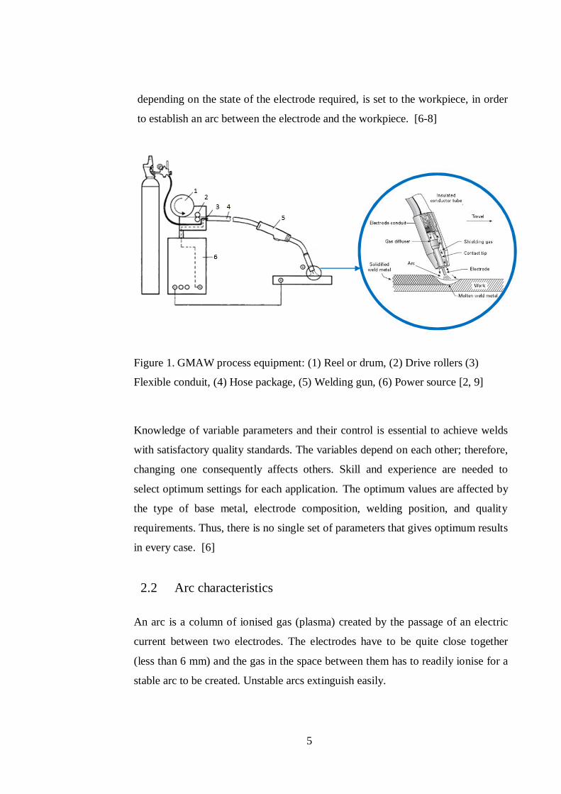
Figure 1. GMAW process equipment: (1) Reel or drum, (2) Drive rollers (3)
Flexible conduit, (4) Hose package, (5) Welding gun, (6) Power source [2,9] .... 5
Figure 2. Schematic diagram, static characteristic curve of the arc [13] ................... 7
Figure 3. Temperature distribution in MIG welding of aluminum at 250 A without
regard to the influence of metal vapour [14] ..................................................... 7
Figure 4. Arc potential (U) distribution between the electrode and the workpiece [2]
.......................................................................................................................... 8
Figure 5. Schematic of temperature-time traces for three points located along a line
perpendicular to a weld during passage of a moving welding heat source for
1018 steel [16] ................................................................................................. 10
Figure 6. Forces acting during droplet transfer [20] ............................................... 12
Figure 7. Forces acting on the drop at a steel electrode tip (argon plasma velocity:
100 m/s) [21] ................................................................................................... 13
Figure 8. Distribution of temperature and current density in the arc and the forces
involved with different shielding gases [23] ..................................................... 14
Figure 9. Arc types and their working ranges, solid wire d=1.2 mm shielding gas:
argon-rich mixtures [24] .................................................................................. 15
Figure 10. Pulsed arc waveform and droplet detachment sequences [25] ............... 16
Figure 11. Transfer by spray arc [27]..................................................................... 16
Figure 12. Voltage and current short circuit metal transfer mode [25] .................... 17
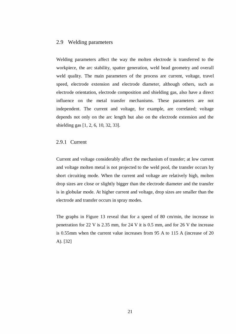
Figure 13. Penetration vs welding current for 80 cm/min with different voltages[32]
........................................................................................................................ 22
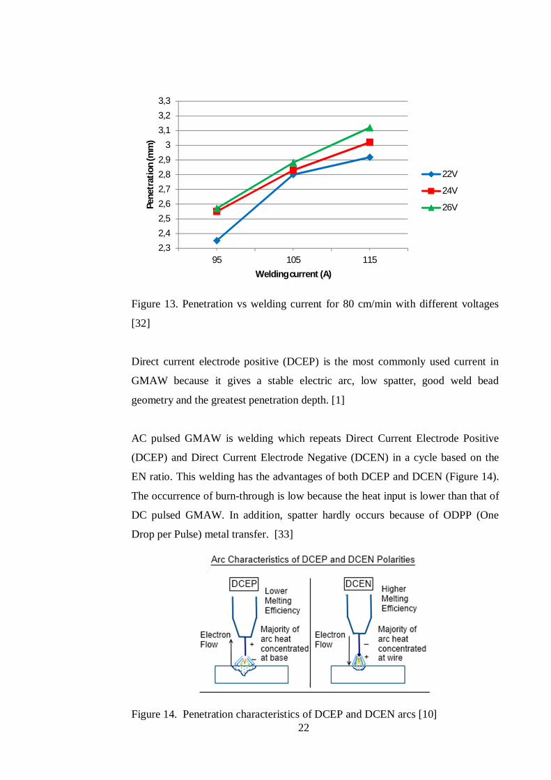
Figure 14. Penetration characteristics of DCEP and DCEN arcs [10] .................... 22
Figure 15. Relationship between weld bead geometry and EN ratio [34] ............... 24
Figure 16. Penetration vs arc voltage graph for 80 cm/min welding speed [32] ...... 25
Figure 17. Relationship between reactor inductance (L) value and welding current
waveform [35] ................................................................................................. 26
Figure 18. Penetration vs welding speed graph for 22V arc voltage [32] ................ 27
Figure 19. Contact Tip-to-Work Distance (CTWD) [6] ......................................... 28
xiv
Figure 20. Melting rate as a function of welding current and wire extension length
with 1.6 mm solid wire in a TIME welding gas mixture [36] ........................... 29
Figure 21. Electric (a) and thermal conductivity (b) of shielding gases at pressure of
1 atm [38, 39] .................................................................................................. 30
Figure 22. Evolution of the penetration with different shielding gas mixtures, with
short-circuits (S.C) and spray (S) transfer [41] ................................................. 31
Figure 23. Effect of gas flow rate on average weld bead penetration [42] .............. 32
Figure 24. Comparison of melting rates in welding with a covered electrode, a solid
wire and a cored wire, respectively [43] ........................................................... 33
Figure 25. Percentage surface fraction of non-metallic inclusions in the weld metals
[48] ................................................................................................................. 40
Figure 26. Fractions of different forms of ferrite in recrystallised structures of weld
metals. [48] ..................................................................................................... 41
Figure 27. Fracture energy in Charpy V-notch tests at -20 °C for weld metals
produced in shields of the investigated gases at different intensity of current [48]
........................................................................................................................ 42
Figure 28. Configuration of digitally-controlled arc welding machine [59] ............ 45
Figure 29. Setting of arc frequency by inductance, capability of control of short-
circuit and arcing time [35] .............................................................................. 47
Figure 30. Pulse waveform of synergic control [72] .............................................. 49
Figure 31. Pulse waveform of self-regulating control [72] ..................................... 49
Figure 32. Dual-pulsed current waveform [77] ..................................................... 50
Figure 33. Current waveform for AC pulsed GMA welding [80] ........................... 51
Figure 34. Waveform current (Is) and voltage (Us) with electrode alternative
feeding motion (Wfs) [90] ............................................................................... 54
Figure 35. Process course, each two positive (EP) and negative (EN) Advanced
CMT cycles [88] ............................................................................................. 55
Figure 36. Graph comparing calculated heat input to actual heat input for P-GMAW
[100] ............................................................................................................... 57
Figure 37. Current waveform of WiseRoot compared with a conventional current
waveform [106] ............................................................................................... 61
Figure 38. Welding current changes with the stick-out length [107]....................... 65
xv
Figure 39. Pulse sequence where the filler droplet short-circuits before detaching
[107] ............................................................................................................... 66
Figure 40. Welding equipment and setting............................................................. 72
Figure 41. Welding design and electrode orientation in horizontal position ........... 73
Figure 42. Weld profile description ....................................................................... 75
Figure 43. Profile repartition of hardness test ........................................................ 75
Figure 44. Bead penetration measurement ............................................................. 76
Figure 45. Filler metal dilution [114] ..................................................................... 76
Figure 46. Increasing gap values bead appearance of the Synergic Pulsed GMAW
process welded specimen. ................................................................................ 78
Figure 47. Increasing gap values bead appearance of the Synergic GMAW process
welded specimen. ............................................................................................ 79
Figure 48. Increasing gap values sample using WiseFusionTM, 35% short circuit ... 79
Figure 49. Increasing gap values sample using WiseFusionTM, 50% short circuit ... 80
Figure 50. Increasing gap values sample using WiseFusionTM, 20% short circuit ... 80
Figure 51. Cross section dilution analysis at 0 air gap (a) Synergic pulsed GMAW
(b) Default curve 35% short circuit .................................................................. 81
Figure 52. Cross section dilution analysis at 1 mm gap (a) Synergic Pulsed GMAW
(b) WiseFusion 35% short circuit, (c) 50% , (d) 20% and (e) Synergic GMAW 83
Figure 53. Cross section dilution analysis at 2 mm gap (a) Synergic Pulsed GMAW
(b) WiseFusion 35% short circuit, (c) 50%, (d) 20% and (e) Synergic GMAW 85
Figure 54. Microstructure of specimen P1.1 Base metal S 355 MC ........................ 90
Figure 55. Microstructure of specimen P1.1 (a) HAZ-Base and (b) Weld .............. 91
Figure 56. Microstructure of specimen P2.1 (a) HAZ-Base and (b) Weld .............. 92
Figure 57. Microstructure of specimen P3.1 (a) HAZ-Base and (b) Weld .............. 93
Figure 58. Microstructure of specimen P4.1 (a) HAZ-Base and (b) Weld .............. 94
Figure 59. Microstructure of specimen P5.1 (a) HAZ-Base and (b) Weld .............. 95
Figure 60. Hardness test results comparison between specimen P1.0 and P2.0....... 96
Figure 61. Hardness test results comparison P1.1, P2.1, P3.1, P4.1 and P5.1 ......... 97
Figure 62. Hardness test results comparison P1.2, P2.2, P3.2, P4.2 and P5.2 ......... 98
xvi
LIST OF TABLES
Table 1. Transfer heat efficiency in GMAW process [11] ........................................ 9
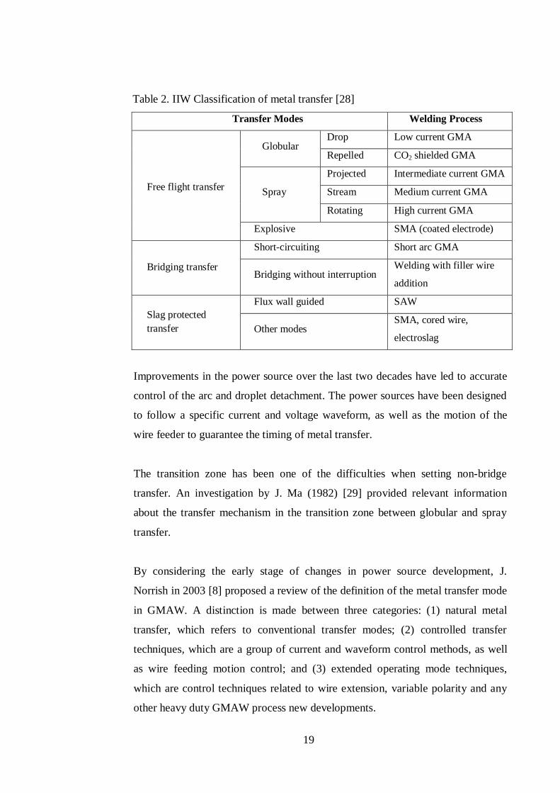
Table 2. IIW Classification of metal transfer [28] .................................................. 19
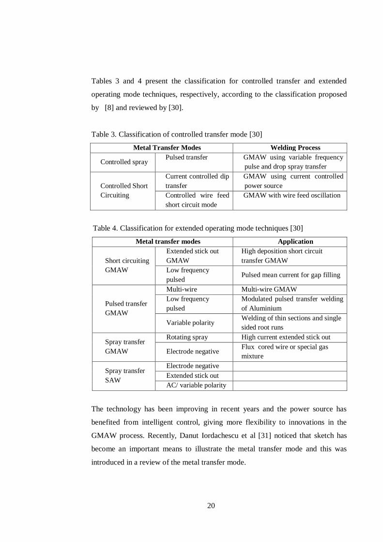
Table 3. Classification of controlled transfer mode [30] ........................................ 20
Table 4. Classification for extended operating mode techniques [30] ..................... 20
Table 5. High current short circuit application and benefits ................................... 36
Table 6 High current spray - application and benefits ............................................ 37
Table 7. Welding parameters example high energy GMAW [48] ........................... 39
Table 8. Comparison between conventional and adaptive GMAW process [102] ... 59
Table 9. Chemical properties of S355 MC [109].................................................... 69
Table 10. Tensile properties transverse of S355 MC [109]..................................... 69
Table 11. Chemical properties of the consumable electrode [111] ......................... 70
Table 12. Welding experiment parameters ............................................................. 77
Table 13. Specimen designation ............................................................................ 81
Table 14. Weld dimension at 0 mm gap ................................................................. 82
Table 15. Weld dimension at 1 mm gap ................................................................. 84
Table 16. Weld dimension at 2 mm gap ................................................................. 86
Table 17. Dilution comparison of P1.0 and P2.0 .................................................... 87
Table 18. Dilution comparison at 1 mm air gap ..................................................... 87
Table 19. Dilution comparison at 2 mm air gap ..................................................... 88
1
1 INTRODUCTION
The development of new materials creates new challenges for the welding
processes used and thereby generates special requirements, such as, welding thin
sheet plate, zinc coated plate, stainless steel and high strength steel and
dissimilar. The new requirements have in the past decade been subject to
particular attention, which has led to major innovations in the field of welding in
general and GMAW in particular. GMAW has benefited from new technological
advances like any other field of industry. Developments in electronics have
enabled the creation of new components with a higher feedback response rate [3,
4]. Digitalisation and the inverter are significant advances for arc welding
because they result in better control of the arc and transmission of metal as
consequence of a more precise and strict monitoring of the voltage and current
waveform. In addition, information sensed at the electrode tip and the CTWD are
fully integrated in the algorithm [5]. It is possible today to control by algorithm;
the current, voltage, displacement of the electrode and the flow of shielding gas.
New methods of welding have demonstrated their successful application in
welding thin sheet plate, dissimilar joint and metal sensitive to heat input. It
should be noted that these new processes are used more in the conventional
voltage range, characterised by a current lower than 200 A and demonstrate
significant reduction in heat input, sparks and smoke.
A major trend today, the development of adaptive GMAW to higher current and
voltage, offers advantages such as high deposition rate and welding speed and
reduces the excessive heat that generates distortion. Utilization of adaptive
GMAW is currently limited to materials sensitive to heat and to thin sheet metal.
Adaptive GMAW provides an improvement in productivity but its use is limited
when welding metals of high thicknesses. Using the arc welding process on
larger thicknesses requires sufficient energy to eliminate the risk of defects such
as insufficient penetration, and lack of fusion between passes and edges of the
workpiece. However, when using excessive high energy the intermetallic is
affected and results in poor quality of physical properties. Conventional GMAW
2
process at high levels has been subjected to a high level of sparks, resulting in
extra cost for cleaning, noise and smoke, and an unstable process that affects the
chemical and physical characteristics of the welded joint.
This study is carried out to identify conditions permitting adoption of new arc
welding methods within the range of high-power energy, which will enhance the
usability of adaptive GMAW, and to assess the limits and benefits. Furthermore,
the results gathered will form the basis for experiments to test the usability of an
adaptive pulsed GMAW and establish optimal applications. Experiments will
define necessary settings for the best results and compare the effectiveness of
droplet detachments control approach to previous ones.
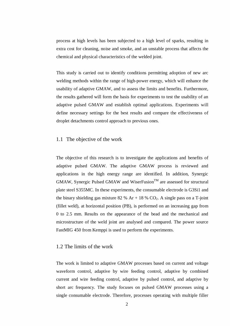
1.1 The objective of the work
The objective of this research is to investigate the applications and benefits of
adaptive pulsed GMAW. The adaptive GMAW process is reviewed and
applications in the high energy range are identified. In addition, Synergic
GMAW, Synergic Pulsed GMAW and WiserFusionTM are assessed for structural
plate steel S355MC. In these experiments, the consumable electrode is G3Si1 and
the binary shielding gas mixture 82 % Ar + 18 % CO2. A single pass on a T-joint
(fillet weld), at horizontal position (PB), is performed on an increasing gap from
0 to 2.5 mm. Results on the appearance of the bead and the mechanical and
microstructure of the weld joint are analysed and compared. The power source
FastMIG 450 from Kemppi is used to perform the experiments.
1.2 The limits of the work
The work is limited to adaptive GMAW processes based on current and voltage
waveform control, adaptive by wire feeding control, adaptive by combined
current and wire feeding control, adaptive by pulsed control, and adaptive by
short arc frequency. The study focuses on pulsed GMAW processes using a
single consumable electrode. Therefore, processes operating with multiple filler

3
wire, such as TAMDEM, or hybrid processes, like those combining laser or TIG
with GMAW, are not mentioned in this thesis.
4
2 CONVENTIONAL GMAW
This section considers the conventional GMAW process, which refers to basic
control of metal transfer. An understanding of the conventional GMAW process
enables, later in this study, comparison with the adaptive GMAW processes.
Firstly, the principle of the process is presented and illustrated with basic
components of the welding equipment. Next, the notion of the arc characteristic
is presented to show in which circumstances the arc generates the necessary
temperature to melt the electrode and to demonstrate the different forces involved
in producing metal deposition. Finally, the metal transfer mechanism and its
classification are presented.
2.1 The process principle
The gas metal arc welding process (GMAW) is an electric arc welding process
that is distinguished from others by a continuously fed consumable electrode. The
welding process to complete the junction of two materials needs a minimum
equipment set-up as shown in Figure 1. While initial settings are required to be
defined by the operator, the equipment provides for automatic self-regulation of
the electrical characteristics of the arc. The welding operation is performed either
manually by the welder for semiautomatic controls, where the operations are the
gun positioning and travel speed and direction, or with full automatic control.
The main role of the power source is to provide the current and voltage required
to maintain the arc and the transfer mechanism of the molten metal from the
electrode to the weld pool. A shielding gas provider device supplies protection
and regulates the flow and mixing quantities indicated for the process. A wire
unit designed to supply the electrode, and whose role is to feed the electrode
through the torch at a precise speed, is an integral part of the equipment. The arc
length and the current (wire feed speed) are automatically maintained by the
equipment and appropriate settings. The torch is used to properly position the
electrode and control the flow of gas to the work area. An anode or cathode,
5
depending on the state of the electrode required, is set to the workpiece, in order
to establish an arc between the electrode and the workpiece. [6-8]
Figure 1. GMAW process equipment: (1) Reel or drum, (2) Drive rollers (3)
Flexible conduit, (4) Hose package, (5) Welding gun, (6) Power source [2, 9]
Knowledge of variable parameters and their control is essential to achieve welds
with satisfactory quality standards. The variables depend on each other; therefore,
changing one consequently affects others. Skill and experience are needed to
select optimum settings for each application. The optimum values are affected by
the type of base metal, electrode composition, welding position, and quality
requirements. Thus, there is no single set of parameters that gives optimum results
in every case. [6]
2.2 Arc characteristics
An arc is a column of ionised gas (plasma) created by the passage of an electric
current between two electrodes. The electrodes have to be quite close together
(less than 6 mm) and the gas in the space between them has to readily ionise for a
stable arc to be created. Unstable arcs extinguish easily.
6
Although the arc can be considered as an electrical resistance or impedance, it
only approximates Ohm’s law at higher current. At low current, the arc voltage
increases as the current is reduced. Welding arcs have a power of the order of 0.6
to 36 kW. This energy creates a column of hot plasma (ionised gas) which is quite
stiff because of electromagnetic forces. It is these electromagnetic forces that
cause transfer of material from the electrode to the workpiece, mould and shape
the weld pool, and even in some cases hold the molten weld pool in place. The
temperature of the arc plasma reaches approximately 6000°C in the GMAW
process [10]. The arc is characterised in terms of its properties: stability, degree of
ionisation, and stiffness. The main factors influencing arc properties are shape of
the anode and cathode, emissivity of the cathode, composition of the ionised
gas/vapour mixture, and electrode material. [11]
It is usual for the arc to be moved along the joint at a steady travel speed. The arc
must generate enough energy to fuse the base and filler material. If it is moved too
quickly, fusion does not occur. Even if fusion occurs, the weld bead may cool
rapidly and crack. If it is moved too slowly the weld pool is large and may be
uncontrollable, or other metallurgical problems may occur. In structural steel,
excessively high arc energy may produces welds with low ductility and toughness.
In quenched and tempered steel, weld strength may be low because of the
extension of the higher heat affected zone (HAZ) and longer cooling rate time,
which affect the microstructure formation and grain size. [12]
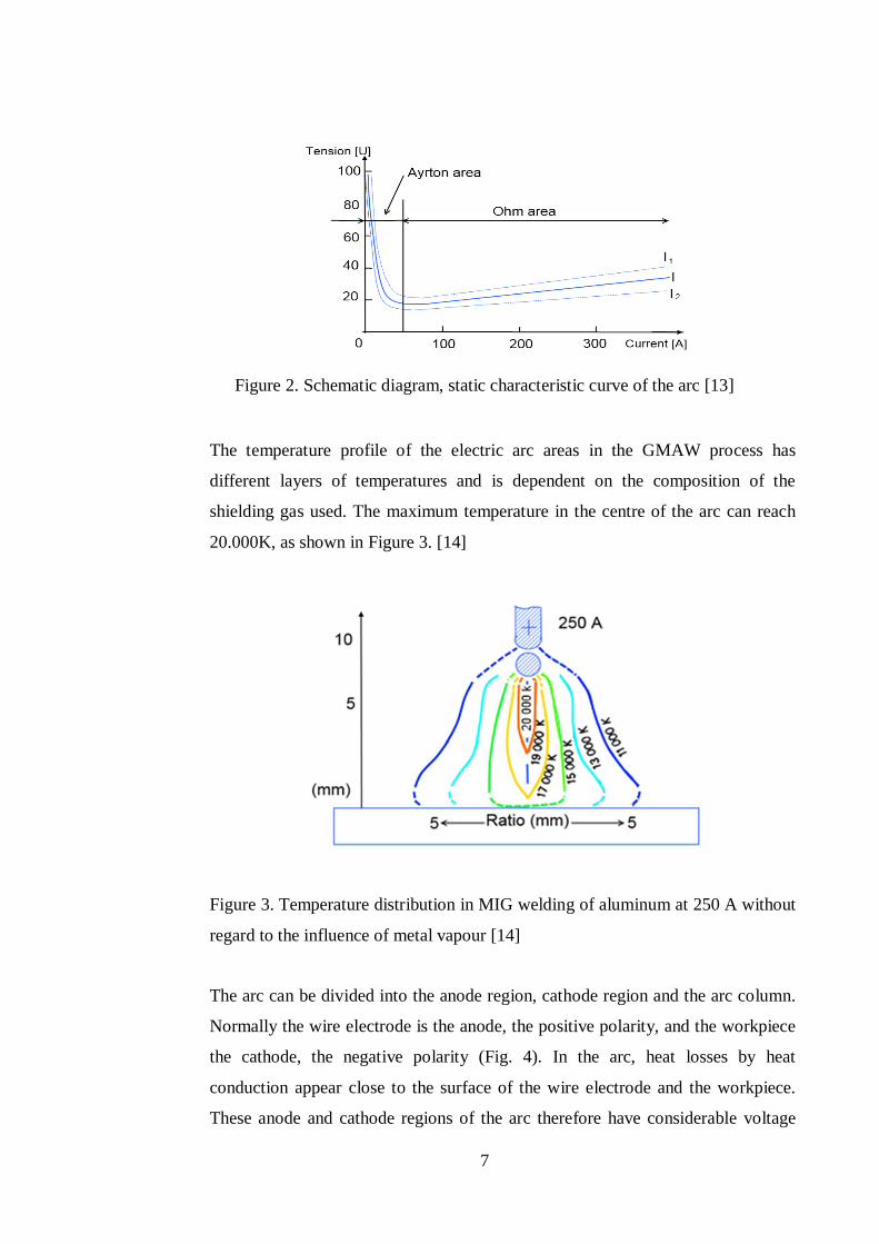
The relationship between voltage and current with a constant length of the arc is
known as the static characteristic. The characteristic curve in GMAW
is a function of arc length, gas composition and protective material electrode. In
the diagram shown in Figure 2 the characteristic curve is divided into two parts,
the Ayrton and Ohm. Only the Ohm part is used for welding because the Ayrton
area is unstable. The curves I, l1 and l2 represent different arc lengths. [13]
7
Figure 2. Schematic diagram, static characteristic curve of the arc [13]
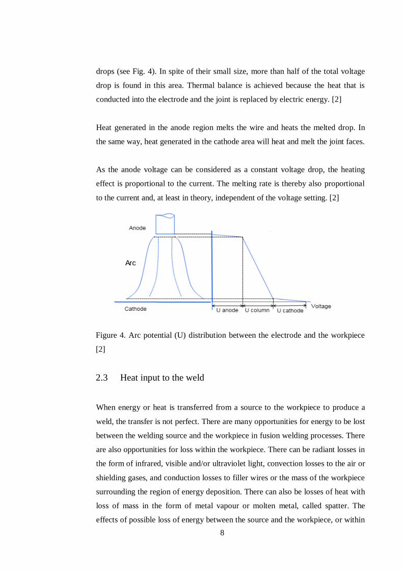
The temperature profile of the electric arc areas in the GMAW process has
different layers of temperatures and is dependent on the composition of the
shielding gas used. The maximum temperature in the centre of the arc can reach
20.000K, as shown in Figure 3. [14]
Figure 3. Temperature distribution in MIG welding of aluminum at 250 A without
regard to the influence of metal vapour [14]
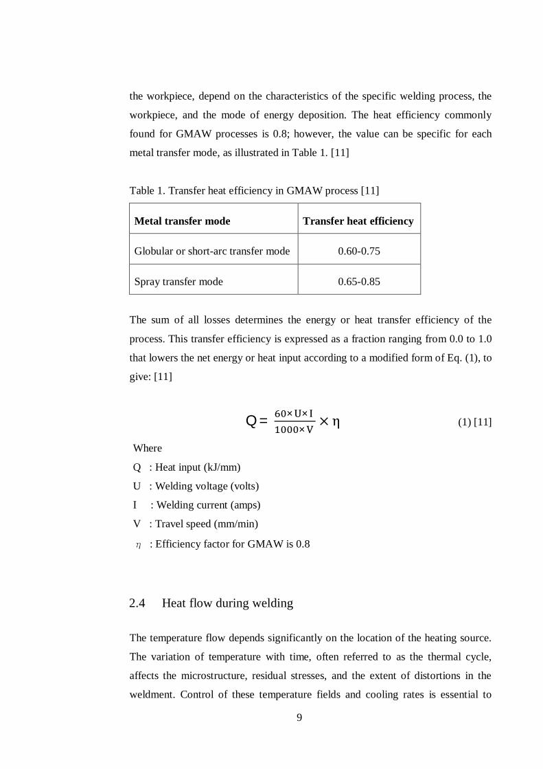
The arc can be divided into the anode region, cathode region and the arc column.
Normally the wire electrode is the anode, the positive polarity, and the workpiece
the cathode, the negative polarity (Fig. 4). In the arc, heat losses by heat
conduction appear close to the surface of the wire electrode and the workpiece.
These anode and cathode regions of the arc therefore have considerable voltage
8
drops (see Fig. 4). In spite of their small size, more than half of the total voltage
drop is found in this area. Thermal balance is achieved because the heat that is
conducted into the electrode and the joint is replaced by electric energy. [2]
Heat generated in the anode region melts the wire and heats the melted drop. In
the same way, heat generated in the cathode area will heat and melt the joint faces.
As the anode voltage can be considered as a constant voltage drop, the heating
effect is proportional to the current. The melting rate is thereby also proportional
to the current and, at least in theory, independent of the voltage setting. [2]
Figure 4. Arc potential (U) distribution between the electrode and the workpiece
[2]
2.3 Heat input to the weld
When energy or heat is transferred from a source to the workpiece to produce a
weld, the transfer is not perfect. There are many opportunities for energy to be lost
between the welding source and the workpiece in fusion welding processes. There
are also opportunities for loss within the workpiece. There can be radiant losses in
the form of infrared, visible and/or ultraviolet light, convection losses to the air or
shielding gases, and conduction losses to filler wires or the mass of the workpiece
surrounding the region of energy deposition. There can also be losses of heat with
loss of mass in the form of metal vapour or molten metal, called spatter. The
effects of possible loss of energy between the source and the workpiece, or within
Arc
9
the workpiece, depend on the characteristics of the specific welding process, the
workpiece, and the mode of energy deposition. The heat efficiency commonly
found for GMAW processes is 0.8; however, the value can be specific for each
metal transfer mode, as illustrated in Table 1. [11]
Table 1. Transfer heat efficiency in GMAW process [11]
Metal transfer mode Transfer heat efficiency
Globular or short-arc transfer mode 0.60-0.75
Spray transfer mode 0.65-0.85
The sum of all losses determines the energy or heat transfer efficiency of the
process. This transfer efficiency is expressed as a fraction ranging from 0.0 to 1.0
that lowers the net energy or heat input according to a modified form of Eq. (1), to
give: [11]
Q = × ××
(1) [11]
Where
Q : Heat input (kJ/mm)
U : Welding voltage (volts)
I : Welding current (amps)
V : Travel speed (mm/min)
: Efficiency factor for GMAW is 0.8
2.4 Heat flow during welding
The temperature flow depends significantly on the location of the heating source.
The variation of temperature with time, often referred to as the thermal cycle,
affects the microstructure, residual stresses, and the extent of distortions in the
weldment. Control of these temperature fields and cooling rates is essential to
10
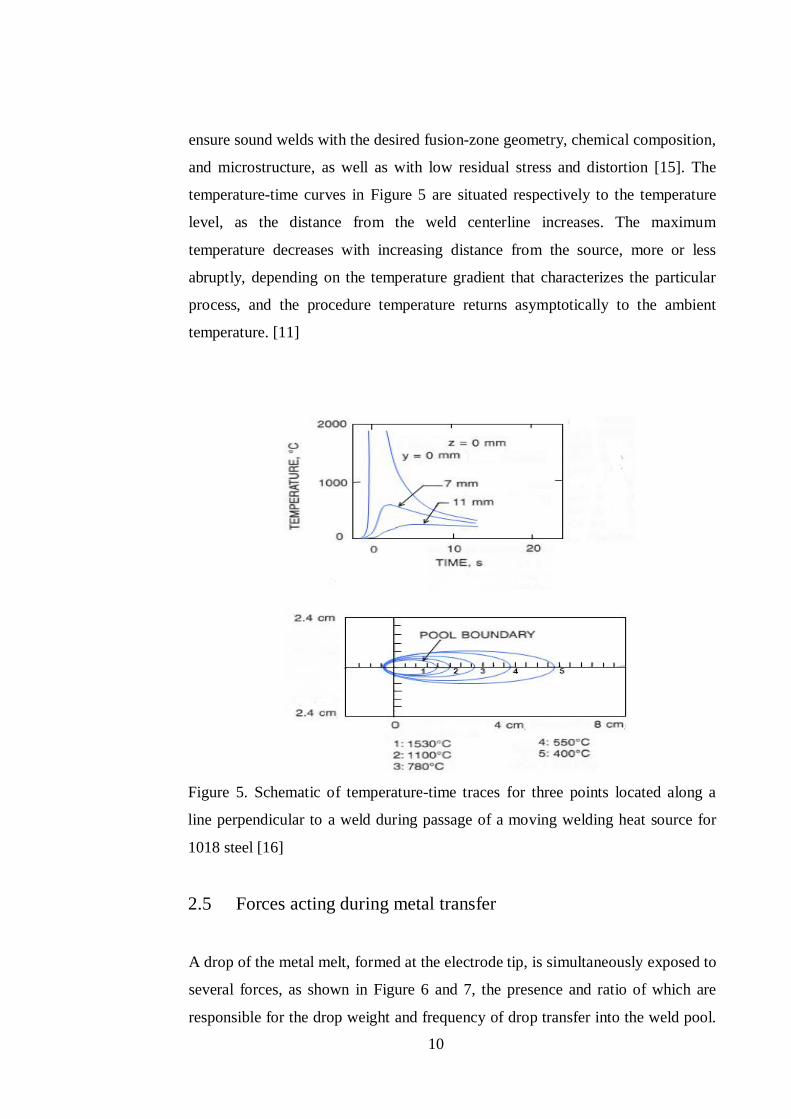
ensure sound welds with the desired fusion-zone geometry, chemical composition,
and microstructure, as well as with low residual stress and distortion [15]. The
temperature-time curves in Figure 5 are situated respectively to the temperature
level, as the distance from the weld centerline increases. The maximum
temperature decreases with increasing distance from the source, more or less
abruptly, depending on the temperature gradient that characterizes the particular
process, and the procedure temperature returns asymptotically to the ambient
temperature. [11]
Figure 5. Schematic of temperature-time traces for three points located along a
line perpendicular to a weld during passage of a moving welding heat source for
1018 steel [16]
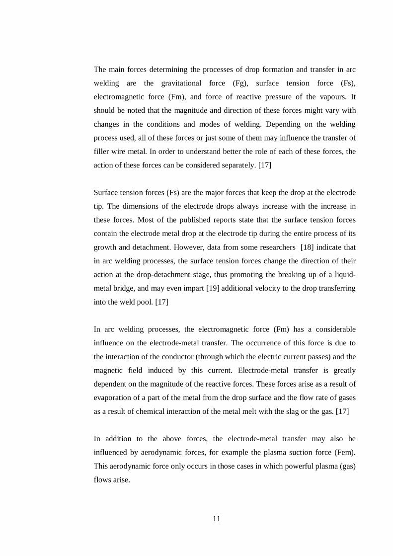
2.5 Forces acting during metal transfer
A drop of the metal melt, formed at the electrode tip, is simultaneously exposed to
several forces, as shown in Figure 6 and 7, the presence and ratio of which are
responsible for the drop weight and frequency of drop transfer into the weld pool.
11
The main forces determining the processes of drop formation and transfer in arc
welding are the gravitational force (Fg), surface tension force (Fs),
electromagnetic force (Fm), and force of reactive pressure of the vapours. It
should be noted that the magnitude and direction of these forces might vary with
changes in the conditions and modes of welding. Depending on the welding
process used, all of these forces or just some of them may influence the transfer of
filler wire metal. In order to understand better the role of each of these forces, the
action of these forces can be considered separately. [17]
Surface tension forces (Fs) are the major forces that keep the drop at the electrode
tip. The dimensions of the electrode drops always increase with the increase in
these forces. Most of the published reports state that the surface tension forces
contain the electrode metal drop at the electrode tip during the entire process of its
growth and detachment. However, data from some researchers [18] indicate that
in arc welding processes, the surface tension forces change the direction of their
action at the drop-detachment stage, thus promoting the breaking up of a liquid-
metal bridge, and may even impart [19] additional velocity to the drop transferring
into the weld pool. [17]
In arc welding processes, the electromagnetic force (Fm) has a considerable
influence on the electrode-metal transfer. The occurrence of this force is due to
the interaction of the conductor (through which the electric current passes) and the
magnetic field induced by this current. Electrode-metal transfer is greatly
dependent on the magnitude of the reactive forces. These forces arise as a result of
evaporation of a part of the metal from the drop surface and the flow rate of gases
as a result of chemical interaction of the metal melt with the slag or the gas. [17]
In addition to the above forces, the electrode-metal transfer may also be
influenced by aerodynamic forces, for example the plasma suction force (Fem).
This aerodynamic force only occurs in those cases in which powerful plasma (gas)
flows arise.
12
Thus, the magnitude and action of the forces affecting the transfer of electrode
metal depend on the chosen fusion welding process, the welding modes, the
properties of the base and electrode materials, the composition of the slag and the
gaseous medium. Therefore, the precise role of each individual force in the
process of electrode-metal transfer is different and will be specific to each
concrete case. [17]
Figure 6. Forces acting during droplet transfer [20]
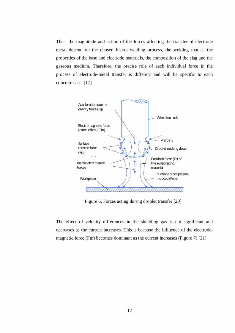
The effect of velocity differences in the shielding gas is not significant and
decreases as the current increases. This is because the influence of the electrode-
magnetic force (Fm) becomes dominant as the current increases (Figure 7) [21].
(Fs)
(Fm)
(Fem)
force (Fg) Wire electrode
Viscosity
Droplet necking down
Backlash force (Fr) of the evaporating material
Suction forces plasma induced (Fem)
Acceleration due to gravity force (Fg)
Electromagnetic force (pinch effect) (Fm)
Surface tension force (Fs)
Inertia electrostatic forces
Workpiece
13
Figure 7. Forces acting on the drop at a steel electrode tip (argon plasma velocity:
100 m/s) [21]
2.6 Effect of shielding gas on the drop transfer
The type of material transfer mode strongly depends on the type of shielding gas
used during the GMAW process. The shielding gas affects the intensity of the
forces acting upon the droplet. In consumable electrode welding, different gases
can have quite different effects on the mode of molten metal transfer. Helium, for
example, does not usually produce an axial spray, regardless of current level or
polarity; transfer remains globular. Spray transfer is also difficult to achieve with
active gases such as nitrogen or carbon-dioxide. The harsh globular transfer and
spatter associated with carbon dioxide as a shielding gas can be offset by adding
argon to stabilize the arc and improve transfer. [11]
Small additions of oxygen or carbon dioxide are commonly added to argon to
stabilize the arc, lower or raise the globular-to-spray transition current,
respectively, and improve wetting and bead shape, especially for welding steel.
[11]
Fs
Fm
Fem
Fg
14
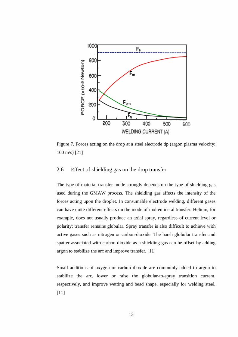
In argon, the current-carrying arc core is wider and envelops the wire electrode
end, as in Figure 8. This generates electromagnetic forces which bring about the
detachment of the liquid electrode material. This so-called “pinch effect” causes a
metal transfer in small drops. The pointed shape of the arc attachment in carbon
dioxide produces a reverse-direction force component, that is, the molten metal is
pushed up until gravity has overcome that force component and material transfer
in the form of very coarse drops appears. [22]
Figure 8. Distribution of temperature and current density in the arc and the forces
involved with different shielding gases [23]
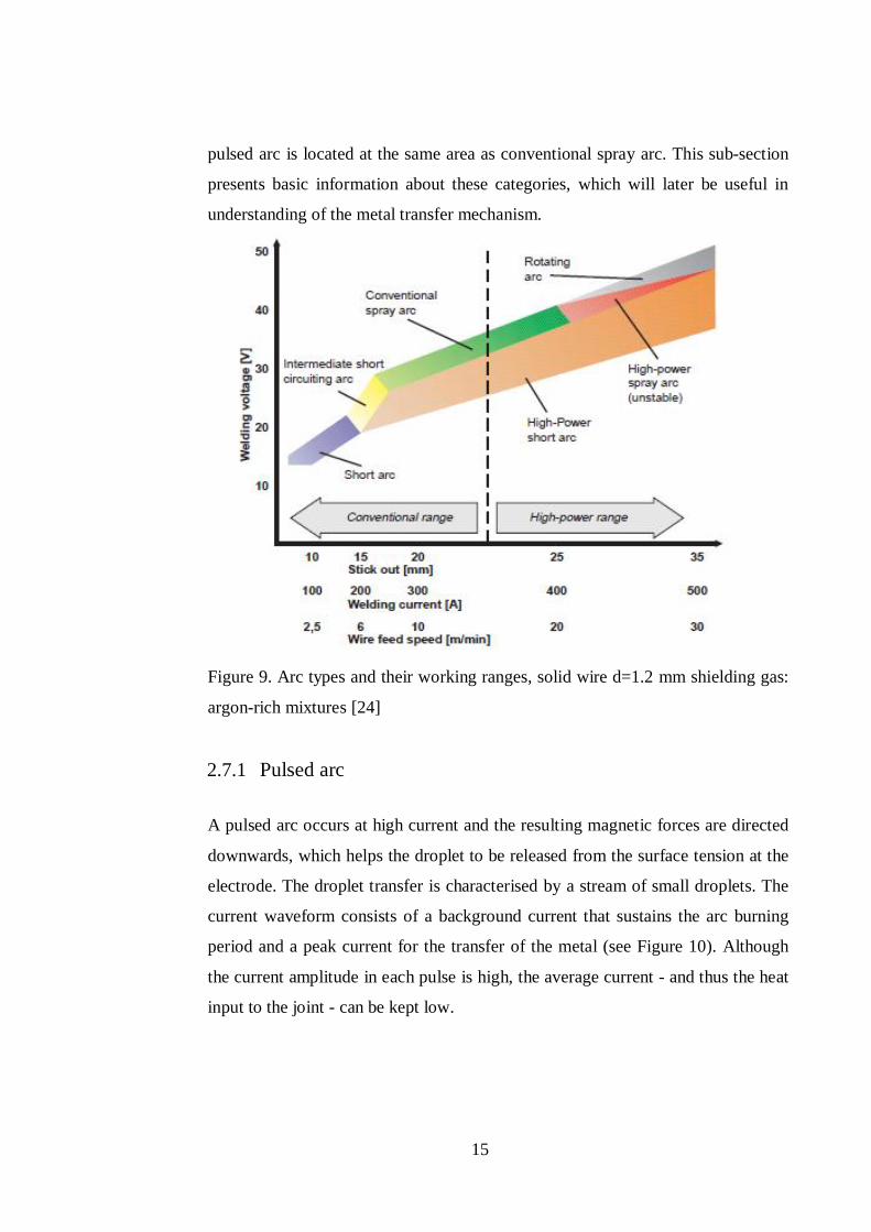
2.7 Classification of different types of arc
In the GMAW process, different types of arc can be generated, depending on the
current, voltage and shielding gas input. Figure 9 shows the different types of arc
generated based on the power loaded. In general, three main groups of arc can be
distinguished; pulsed arc, spray arc and short circuiting arc. The peak current of
15
pulsed arc is located at the same area as conventional spray arc. This sub-section
presents basic information about these categories, which will later be useful in
understanding of the metal transfer mechanism.
Figure 9. Arc types and their working ranges, solid wire d=1.2 mm shielding gas:
argon-rich mixtures [24]
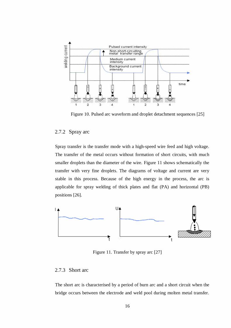
2.7.1 Pulsed arc
A pulsed arc occurs at high current and the resulting magnetic forces are directed
downwards, which helps the droplet to be released from the surface tension at the
electrode. The droplet transfer is characterised by a stream of small droplets. The
current waveform consists of a background current that sustains the arc burning
period and a peak current for the transfer of the metal (see Figure 10). Although
the current amplitude in each pulse is high, the average current - and thus the heat
input to the joint - can be kept low.
16
Figure 10. Pulsed arc waveform and droplet detachment sequences [25]
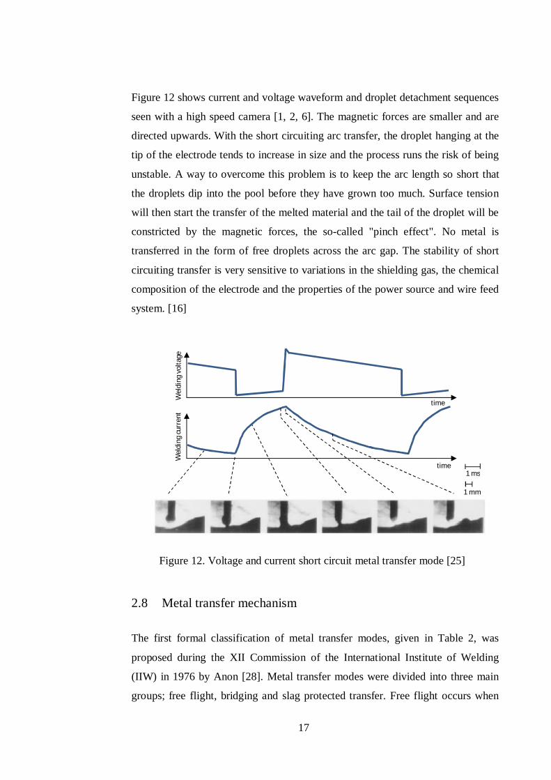
2.7.2 Spray arc
Spray transfer is the transfer mode with a high-speed wire feed and high voltage.
The transfer of the metal occurs without formation of short circuits, with much
smaller droplets than the diameter of the wire. Figure 11 shows schematically the
transfer with very fine droplets. The diagrams of voltage and current are very
stable in this process. Because of the high energy in the process, the arc is
applicable for spray welding of thick plates and flat (PA) and horizontal (PB)
positions [26].
Figure 11. Transfer by spray arc [27]
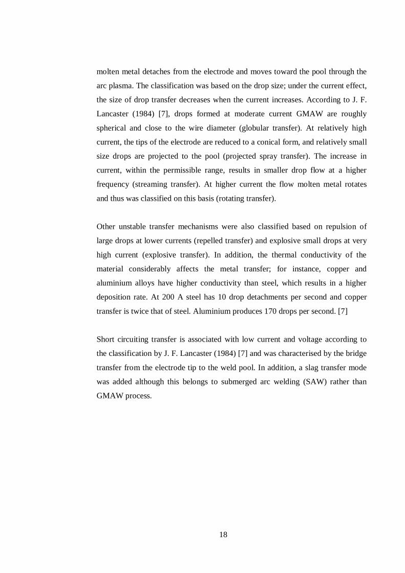
2.7.3 Short arc
The short arc is characterised by a period of burn arc and a short circuit when the
bridge occurs between the electrode and weld pool during molten metal transfer.
17
Figure 12 shows current and voltage waveform and droplet detachment sequences
seen with a high speed camera [1, 2, 6]. The magnetic forces are smaller and are
directed upwards. With the short circuiting arc transfer, the droplet hanging at the
tip of the electrode tends to increase in size and the process runs the risk of being
unstable. A way to overcome this problem is to keep the arc length so short that
the droplets dip into the pool before they have grown too much. Surface tension
will then start the transfer of the melted material and the tail of the droplet will be
constricted by the magnetic forces, the so-called "pinch effect". No metal is
transferred in the form of free droplets across the arc gap. The stability of short
circuiting transfer is very sensitive to variations in the shielding gas, the chemical
composition of the electrode and the properties of the power source and wire feed
system. [16]
Figure 12. Voltage and current short circuit metal transfer mode [25]
2.8 Metal transfer mechanism
The first formal classification of metal transfer modes, given in Table 2, was
proposed during the XII Commission of the International Institute of Welding
(IIW) in 1976 by Anon [28]. Metal transfer modes were divided into three main
groups; free flight, bridging and slag protected transfer. Free flight occurs when
Wel
ding
vol
tage
W
eldi
ng c
urre
nt
1 ms
time
time
1 mm
18
molten metal detaches from the electrode and moves toward the pool through the
arc plasma. The classification was based on the drop size; under the current effect,
the size of drop transfer decreases when the current increases. According to J. F.
Lancaster (1984) [7], drops formed at moderate current GMAW are roughly
spherical and close to the wire diameter (globular transfer). At relatively high
current, the tips of the electrode are reduced to a conical form, and relatively small
size drops are projected to the pool (projected spray transfer). The increase in
current, within the permissible range, results in smaller drop flow at a higher
frequency (streaming transfer). At higher current the flow molten metal rotates
and thus was classified on this basis (rotating transfer).
Other unstable transfer mechanisms were also classified based on repulsion of
large drops at lower currents (repelled transfer) and explosive small drops at very
high current (explosive transfer). In addition, the thermal conductivity of the
material considerably affects the metal transfer; for instance, copper and
aluminium alloys have higher conductivity than steel, which results in a higher
deposition rate. At 200 A steel has 10 drop detachments per second and copper
transfer is twice that of steel. Aluminium produces 170 drops per second. [7]
Short circuiting transfer is associated with low current and voltage according to
the classification by J. F. Lancaster (1984) [7] and was characterised by the bridge
transfer from the electrode tip to the weld pool. In addition, a slag transfer mode
was added although this belongs to submerged arc welding (SAW) rather than
GMAW process.
19
Table 2. IIW Classification of metal transfer [28]
Transfer Modes Welding Process
Free flight transfer
Globular Drop Low current GMA
Repelled CO2 shielded GMA
Spray
Projected Intermediate current GMA
Stream Medium current GMA
Rotating High current GMA
Explosive SMA (coated electrode)
Bridging transfer
Short-circuiting Short arc GMA
Bridging without interruption Welding with filler wire
addition
Slag protected transfer
Flux wall guided SAW
Other modes SMA, cored wire,
electroslag
Improvements in the power source over the last two decades have led to accurate
control of the arc and droplet detachment. The power sources have been designed
to follow a specific current and voltage waveform, as well as the motion of the
wire feeder to guarantee the timing of metal transfer.
The transition zone has been one of the difficulties when setting non-bridge
transfer. An investigation by J. Ma (1982) [29] provided relevant information
about the transfer mechanism in the transition zone between globular and spray
transfer.
By considering the early stage of changes in power source development, J.
Norrish in 2003 [8] proposed a review of the definition of the metal transfer mode
in GMAW. A distinction is made between three categories: (1) natural metal
transfer, which refers to conventional transfer modes; (2) controlled transfer
techniques, which are a group of current and waveform control methods, as well
as wire feeding motion control; and (3) extended operating mode techniques,
which are control techniques related to wire extension, variable polarity and any
other heavy duty GMAW process new developments.
20
Tables 3 and 4 present the classification for controlled transfer and extended
operating mode techniques, respectively, according to the classification proposed
by [8] and reviewed by [30].
Table 3. Classification of controlled transfer mode [30]
Metal Transfer Modes Welding Process
Controlled spray Pulsed transfer GMAW using variable frequency pulse and drop spray transfer
Controlled Short Circuiting
Current controlled dip transfer
GMAW using current controlled power source
Controlled wire feed short circuit mode
GMAW with wire feed oscillation
Table 4. Classification for extended operating mode techniques [30]
Metal transfer modes Application
Short circuiting GMAW
Extended stick out GMAW
High deposition short circuit transfer GMAW
Low frequency pulsed Pulsed mean current for gap filling
Pulsed transfer GMAW
Multi-wire Multi-wire GMAW Low frequency pulsed
Modulated pulsed transfer welding of Aluminium
Variable polarity Welding of thin sections and single sided root runs
Spray transfer GMAW
Rotating spray High current extended stick out
Electrode negative Flux cored wire or special gas mixture
Spray transfer SAW
Electrode negative Extended stick out AC/ variable polarity
The technology has been improving in recent years and the power source has
benefited from intelligent control, giving more flexibility to innovations in the
GMAW process. Recently, Danut Iordachescu et al [31] noticed that sketch has
become an important means to illustrate the metal transfer mode and this was
introduced in a review of the metal transfer mode.
21
2.9 Welding parameters
Welding parameters affect the way the molten electrode is transferred to the
workpiece, the arc stability, spatter generation, weld bead geometry and overall
weld quality. The main parameters of the process are current, voltage, travel
speed, electrode extension and electrode diameter, although others, such as
electrode orientation, electrode composition and shielding gas, also have a direct
influence on the metal transfer mechanisms. These parameters are not
independent. The current and voltage, for example, are correlated; voltage
depends not only on the arc length but also on the electrode extension and the
shielding gas [1, 2, 6, 10, 32, 33].
2.9.1 Current
Current and voltage considerably affect the mechanism of transfer; at low current
and voltage molten metal is not projected to the weld pool, the transfer occurs by
short circuiting mode. When the current and voltage are relatively high, molten
drop sizes are close or slightly bigger than the electrode diameter and the transfer
is in globular mode. At higher current and voltage, drop sizes are smaller than the
electrode and transfer occurs in spray modes.
The graphs in Figure 13 reveal that for a speed of 80 cm/min, the increase in
penetration for 22 V is 2.35 mm, for 24 V it is 0.5 mm, and for 26 V the increase
is 0.55mm when the current value increases from 95 A to 115 A (increase of 20
A). [32]
22
Figure 13. Penetration vs welding current for 80 cm/min with different voltages
[32]
Direct current electrode positive (DCEP) is the most commonly used current in
GMAW because it gives a stable electric arc, low spatter, good weld bead
geometry and the greatest penetration depth. [1]
AC pulsed GMAW is welding which repeats Direct Current Electrode Positive
(DCEP) and Direct Current Electrode Negative (DCEN) in a cycle based on the
EN ratio. This welding has the advantages of both DCEP and DCEN (Figure 14).
The occurrence of burn-through is low because the heat input is lower than that of
DC pulsed GMAW. In addition, spatter hardly occurs because of ODPP (One
Drop per Pulse) metal transfer. [33]
Figure 14. Penetration characteristics of DCEP and DCEN arcs [10]
2,32,42,52,62,72,82,9
33,13,23,3
95 105 115
Pene
trat
ion
(mm
)
Welding current (A)
22V
24V
26V
23
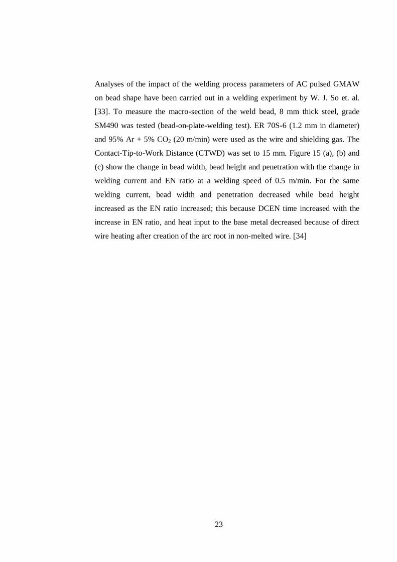
Analyses of the impact of the welding process parameters of AC pulsed GMAW
on bead shape have been carried out in a welding experiment by W. J. So et. al.
[33]. To measure the macro-section of the weld bead, 8 mm thick steel, grade
SM490 was tested (bead-on-plate-welding test). ER 70S-6 (1.2 mm in diameter)
and 95% Ar + 5% CO2 (20 m/min) were used as the wire and shielding gas. The
Contact-Tip-to-Work Distance (CTWD) was set to 15 mm. Figure 15 (a), (b) and
(c) show the change in bead width, bead height and penetration with the change in
welding current and EN ratio at a welding speed of 0.5 m/min. For the same
welding current, bead width and penetration decreased while bead height
increased as the EN ratio increased; this because DCEN time increased with the
increase in EN ratio, and heat input to the base metal decreased because of direct
wire heating after creation of the arc root in non-melted wire. [34]
24
(a) Bead width
(b) Bead height
(c) Penetration
Figure 15. Relationship between weld bead geometry and EN ratio [34]
0
2
4
6
8
10
12
0 10 20 30
Bead
wid
th (m
m)
EN ratio (%)
I=100A
I=150A
I=200A
I= 250A
0
0,5
1
1,5
2
2,5
3
0 10 20 30
Bead
hei
ght (
mm
)
EN ratio (%)
I=100A
I=150A
I=200A
I= 250A
00,5
11,5
22,5
33,5
44,5
0 10 20 30
Pene
trat
ion
(mm
)
EN ratio (%)
I=100A
I=150A
I=200A
I= 250A
25
2.9.2 Voltage
Arc voltage is directly related to current, as indicated above, and increased arc
length increases voltage. Arc voltage also depends on the shielding gas and
electrode extension. An increase in arc voltage widens and flattens the weld bead.
Low voltages increase the weld reinforcement and excessively high voltages can
cause arc instability, spatter and porosity, and even undercut. [2, 6]
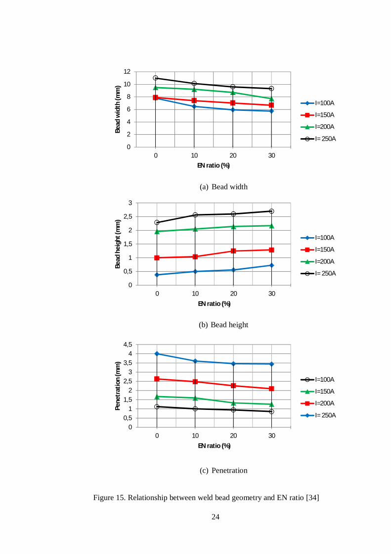
The graphs in Figure 16 show that for a speed of 80 cm/min, the increase in depth
of penetration for 95 A, 105 A and 115 A is 0.19, 0.15 and 0.18 mm, respectively,
for an increase of 4 V. [32]
Figure 16. Penetration vs arc voltage graph for 80 cm/min welding speed [32]
2.9.3 Inductance
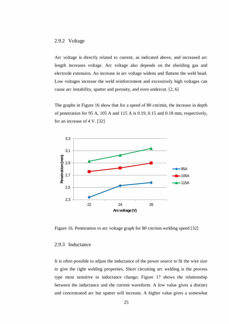
It is often possible to adjust the inductance of the power source to fit the wire size
to give the right welding properties. Short circuiting arc welding is the process
type most sensitive to inductance change; Figure 17 shows the relationship
between the inductance and the current waveform. A low value gives a distinct
and concentrated arc but spatter will increase. A higher value gives a somewhat
2,3
2,5
2,7
2,9
3,1
3,3
22 24 26
Pene
trat
ion
(mm
)
Arc voltage (V)
95A
105A
115A
26
wider bead and a softer sounding. Too high inductance gives bad stability with a
tendency for stubbing. Inductance may be replaced by greater drooping
characteristics curves of the power source. In inverter power sources, the dynamic
properties of the power source are normally managed by digital or electronic
control circuits. [2, 6]
Figure 17. Relationship between reactor inductance (L) value and welding current
waveform [35]
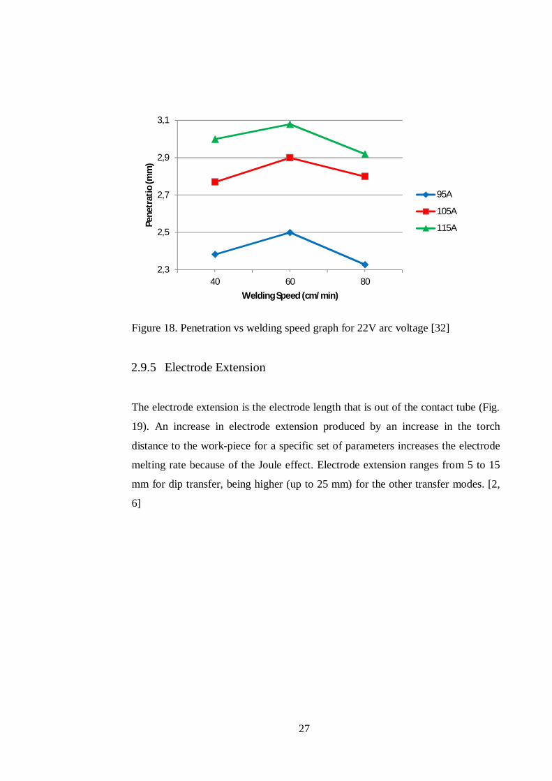
2.9.4 Welding Speed
Increase in welding speed leads to growth in productivity. Increase in the welding
speed results in a decrease in the linear heat input to the workpiece and the filler
metal deposition rate per unit of length. The initial increase in welding speed can
cause some increase in penetration depth, because the arc acts more directly in the
parent material, but further increase in speed decreases penetration and can cause
undercut, due to insufficient material to fill the cavity produced by the arc. [2, 6]
The graphs in Figure 18 suggest that as the welding speed increases, the depth of
penetration increases. However, it decreases as the speed is increased beyond 60
cm/min. This indicates that for any welding condition, there is an optimum value
of welding speed beyond which if the speed is increased, the depth of penetration
decreases. [32]
High (L)
t1, t’1 t2 t’2
Low (L)
Curr
ent
27
Figure 18. Penetration vs welding speed graph for 22V arc voltage [32]
2.9.5 Electrode Extension
The electrode extension is the electrode length that is out of the contact tube (Fig.
19). An increase in electrode extension produced by an increase in the torch
distance to the work-piece for a specific set of parameters increases the electrode
melting rate because of the Joule effect. Electrode extension ranges from 5 to 15
mm for dip transfer, being higher (up to 25 mm) for the other transfer modes. [2,
6]
2,3
2,5
2,7
2,9
3,1
40 60 80
Pene
trat
io (m
m)
Welding Speed (cm/min)
95A
105A
115A
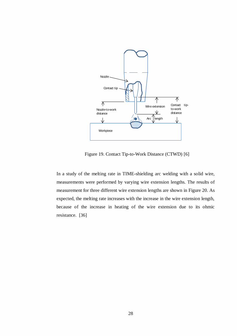
28
Figure 19. Contact Tip-to-Work Distance (CTWD) [6]
In a study of the melting rate in TIME-shielding arc welding with a solid wire,
measurements were performed by varying wire extension lengths. The results of
measurement for three different wire extension lengths are shown in Figure 20. As
expected, the melting rate increases with the increase in the wire extension length,
because of the increase in heating of the wire extension due to its ohmic
resistance. [36]
Nozzle
Contact tip
Nozzle-to-work distance
Contact tip-to-work distance
Wire extension
Arc length
Workpiece
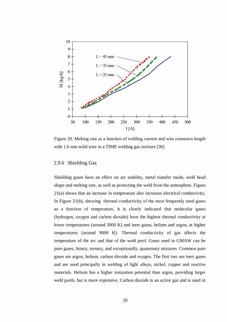
29
Figure 20. Melting rate as a function of welding current and wire extension length
with 1.6 mm solid wire in a TIME welding gas mixture [36]
2.9.6 Shielding Gas
Shielding gases have an effect on arc stability, metal transfer mode, weld bead
shape and melting rate, as well as protecting the weld from the atmosphere. Figure
21(a) shows that an increase in temperature also increases electrical conductivity.
In Figure 21(b), showing thermal conductivity of the most frequently used gases
as a function of temperature, it is clearly indicated that molecular gases
(hydrogen, oxygen and carbon dioxide) have the highest thermal conductivity at
lower temperatures (around 3000 K) and inert gases, helium and argon, at higher
temperatures (around 9000 K). Thermal conductivity of gas affects the
temperature of the arc and that of the weld pool. Gases used in GMAW can be
pure gases, binary, ternary, and exceptionally, quaternary mixtures. Common pure
gases are argon, helium, carbon dioxide and oxygen. The first two are inert gases
and are used principally in welding of light alloys, nickel, copper and reactive
materials. Helium has a higher ionization potential than argon, providing larger
weld pools, but is more expensive. Carbon dioxide is an active gas and is used in
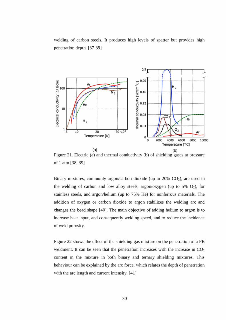
30
welding of carbon steels. It produces high levels of spatter but provides high
penetration depth. [37-39]
Figure 21. Electric (a) and thermal conductivity (b) of shielding gases at pressure
of 1 atm [38, 39]
Binary mixtures, commonly argon/carbon dioxide (up to 20% CO2), are used in
the welding of carbon and low alloy steels, argon/oxygen (up to 5% O2), for
stainless steels, and argon/helium (up to 75% He) for nonferrous materials. The
addition of oxygen or carbon dioxide to argon stabilizes the welding arc and
changes the bead shape [40]. The main objective of adding helium to argon is to
increase heat input, and consequently welding speed, and to reduce the incidence
of weld porosity.
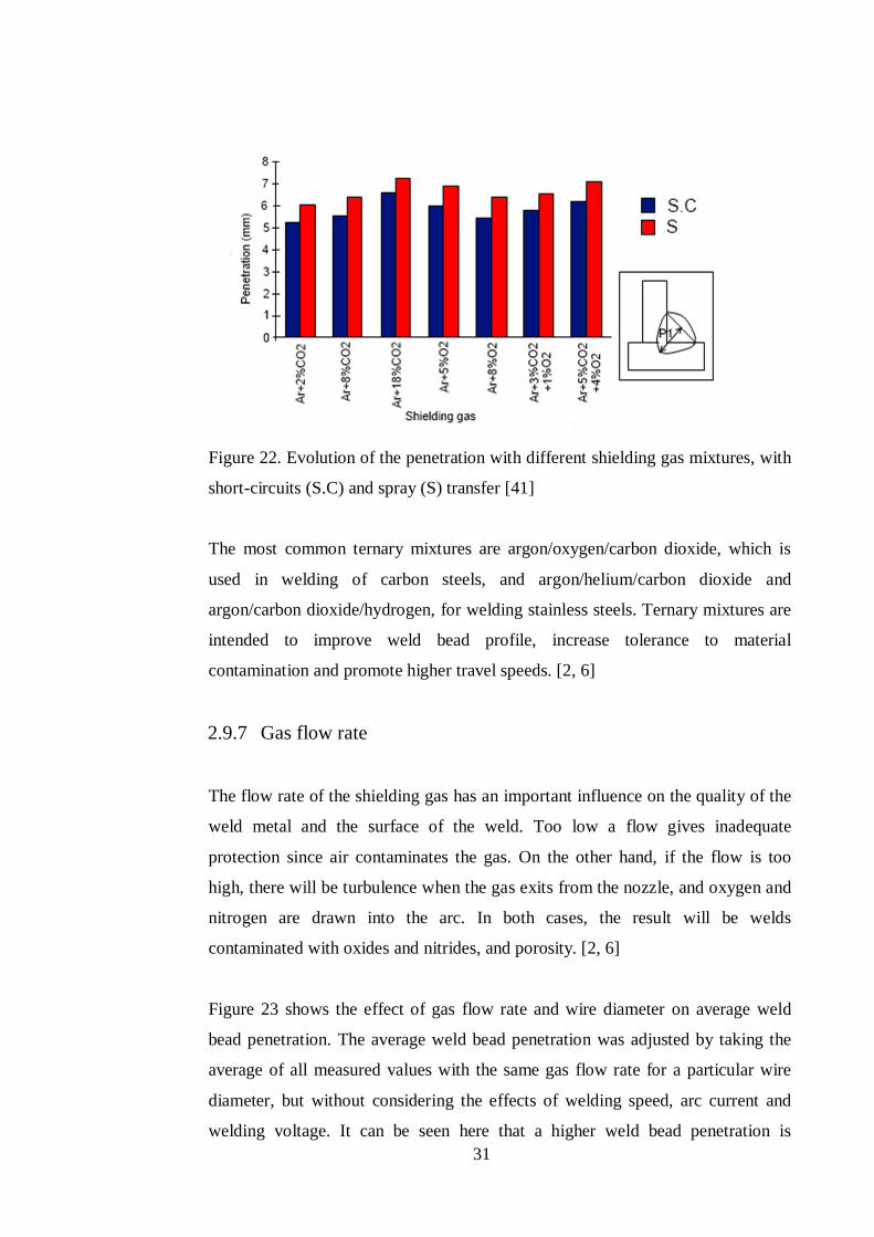
Figure 22 shows the effect of the shielding gas mixture on the penetration of a PB
weldment. It can be seen that the penetration increases with the increase in CO2
content in the mixture in both binary and ternary shielding mixtures. This
behaviour can be explained by the arc force, which relates the depth of penetration
with the arc length and current intensity. [41]
(a) (b)
31
Figure 22. Evolution of the penetration with different shielding gas mixtures, with
short-circuits (S.C) and spray (S) transfer [41]
The most common ternary mixtures are argon/oxygen/carbon dioxide, which is
used in welding of carbon steels, and argon/helium/carbon dioxide and
argon/carbon dioxide/hydrogen, for welding stainless steels. Ternary mixtures are
intended to improve weld bead profile, increase tolerance to material
contamination and promote higher travel speeds. [2, 6]
2.9.7 Gas flow rate
The flow rate of the shielding gas has an important influence on the quality of the
weld metal and the surface of the weld. Too low a flow gives inadequate
protection since air contaminates the gas. On the other hand, if the flow is too
high, there will be turbulence when the gas exits from the nozzle, and oxygen and
nitrogen are drawn into the arc. In both cases, the result will be welds
contaminated with oxides and nitrides, and porosity. [2, 6]
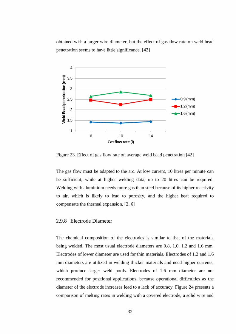
Figure 23 shows the effect of gas flow rate and wire diameter on average weld
bead penetration. The average weld bead penetration was adjusted by taking the
average of all measured values with the same gas flow rate for a particular wire
diameter, but without considering the effects of welding speed, arc current and
welding voltage. It can be seen here that a higher weld bead penetration is
32
obtained with a larger wire diameter, but the effect of gas flow rate on weld bead
penetration seems to have little significance. [42]
Figure 23. Effect of gas flow rate on average weld bead penetration [42]
The gas flow must be adapted to the arc. At low current, 10 litres per minute can
be sufficient, while at higher welding data, up to 20 litres can be required.
Welding with aluminium needs more gas than steel because of its higher reactivity
to air, which is likely to lead to porosity, and the higher heat required to
compensate the thermal expansion. [2, 6]
2.9.8 Electrode Diameter
The chemical composition of the electrodes is similar to that of the materials
being welded. The most usual electrode diameters are 0.8, 1.0, 1.2 and 1.6 mm.
Electrodes of lower diameter are used for thin materials. Electrodes of 1.2 and 1.6
mm diameters are utilized in welding thicker materials and need higher currents,
which produce larger weld pools. Electrodes of 1.6 mm diameter are not
recommended for positional applications, because operational difficulties as the
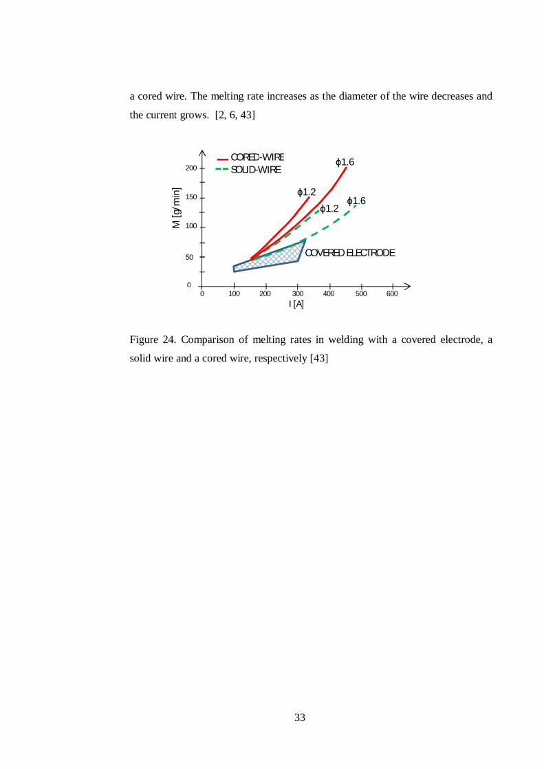
diameter of the electrode increases lead to a lack of accuracy. Figure 24 presents a
comparison of melting rates in welding with a covered electrode, a solid wire and
1
1,5
2
2,5
3
3,5
4
6 10 14
Wel
d Be
ad p
enet
ratio
n (m
m)
Gas flow rate (l)
0,9 (mm)
1,2 (mm)
1,6 (mm)
33
a cored wire. The melting rate increases as the diameter of the wire decreases and
the current grows. [2, 6, 43]
Figure 24. Comparison of melting rates in welding with a covered electrode, a
solid wire and a cored wire, respectively [43]
M [g
/min
] 1.6
1.6 1.2
1.2
CORED-WIRE SOLID-WIRE
COVERED ELECTRODE
0 100 200 300 400 500 600 I [A]
200
150
100
50
0
34
3 HIGH ARC ENERGY
Investigations carried out by many manufacturers of welding equipment and
materials into opportunities for improving the efficiency of the GMAW welding
process have resulted in the introduction of some new variants of this method. In
particular, these explore specific characteristics of the arc that come into being
when the high energy of the system is combined with high rates of wire feed,
longer CTWD and the chemical composition of the shielding gas. The deposition
rate reached in processes of this kind is 10-14 kg/hr, but when high-energy
sources are employed, it may even rise to some 27 kg/hr. The area of applications
covered by high arc energy welding methods includes the manufacture of
constructions welded in thick plates and in thick-walled tubing. The ever-
growing popularity of these variants of high arc welding is associated with the
high efficiency of the arc compared with the standard GMAW process, and with
the good properties of welds which are deposited at high values of arc
parameters. According to some research [44-46], the differences between
individual variants of the process manifest themselves almost entirely in the
chemical composition of the recommended shielding gases, leaving other
characteristics of the process almost unchanged. However, other works [36, 47,
48] indicate that the gas mixture has a negligible effect on the efficiency and the
weld properties.
3.1 High current short circuiting arc
The high-power short arc, called a RapidArc or ForcedArc, is characterized by
the use of a reduced welding voltage. At its earlier approach the process was
performed with moderately lower voltage combined with a high wire feed speed
and welding current which resulted in a high penetration (forced) short arc with a
high frequency, approximately 150-400 Hz [2].
The droplet attachment at the end of the electrode grows until it touches the
molten pool via a shorting bridge. In consequence, the arc extinguishes, and thus,
the high welding current causes a high pinch force, which constricts the shorting
35
bridge to an increasingly greater extent. Finally, the surface tension of the molten
pool takes off the droplet [49]. The arc re-ignites and the process is repeated [45].
Thus, the liquid end of the electrode periodically causes short circuits. The radial
force of the magnetic field may deflect the droplet a little out of its symmetry
axis [50]. In contrast to conventional short-arc welding, the short-circuit duration
is shorter because of the more extreme pinch effect, and the droplet frequency is
higher [24].
The arc has a sharper sound than a conventional short arc. The relatively low
welding voltage enables a faster welding speed without undercut. At the same
time, the risk for large weld reinforcement (due to the low voltage) is limited by
selection of an appropriate combination of the welding parameters, such as
welding speed, shielding gas mixture and gas flow rate. An argon-based (92 %
Ar + 8 % CO2) shielding gas is used with a higher gas flow than normal (20
l/min) [2].
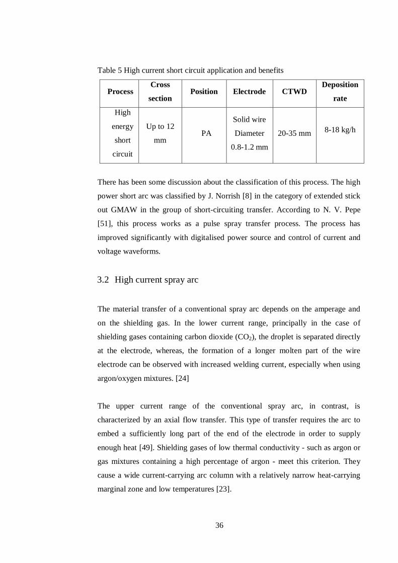
The process is used for welding smaller weld sizes with high travel speeds. Table
5 presents some important applications and the benefits of the high-energy short
circuit GMAW process. Thin sheet and medium thick steels (up to 12 mm) are
suitable for welding with a high current short circuiting arc since the heat input is
low but with maintained fusion capacity (lower thermal losses to the material due
to the high travel speed). Mechanised welding is necessary to make full use of the
process. In addition, due to the long electrode extension, approximately 20-35
mm, an automated system is required for good repeatability to ensure a high weld
quality. The welding position also has an important role; high quality weldments
are achieved in the horizontal position (PA). Solid wires with diameters between
0.8 and 1.2 mm are used and deposition rates between 8 and 18 kg/h can be
achieved. An interesting aspect of this method is that normal welding equipment
can be used. [2]
36
Table 5 High current short circuit application and benefits
Process Cross
section Position Electrode CTWD
Deposition
rate
High
energy
short
circuit
Up to 12
mm PA
Solid wire
Diameter
0.8-1.2 mm
20-35 mm 8-18 kg/h
There has been some discussion about the classification of this process. The high
power short arc was classified by J. Norrish [8] in the category of extended stick
out GMAW in the group of short-circuiting transfer. According to N. V. Pepe
[51], this process works as a pulse spray transfer process. The process has
improved significantly with digitalised power source and control of current and
voltage waveforms.
3.2 High current spray arc
The material transfer of a conventional spray arc depends on the amperage and
on the shielding gas. In the lower current range, principally in the case of
shielding gases containing carbon dioxide (CO2), the droplet is separated directly
at the electrode, whereas, the formation of a longer molten part of the wire
electrode can be observed with increased welding current, especially when using
argon/oxygen mixtures. [24]
The upper current range of the conventional spray arc, in contrast, is
characterized by an axial flow transfer. This type of transfer requires the arc to
embed a sufficiently long part of the end of the electrode in order to supply
enough heat [49]. Shielding gases of low thermal conductivity - such as argon or
gas mixtures containing a high percentage of argon - meet this criterion. They
cause a wide current-carrying arc column with a relatively narrow heat-carrying
marginal zone and low temperatures [23].
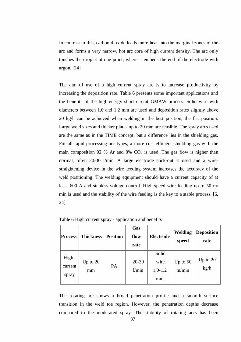
37
In contrast to this, carbon dioxide leads more heat into the marginal zones of the
arc and forms a very narrow, hot arc core of high current density. The arc only
touches the droplet at one point, where it embeds the end of the electrode with
argon. [24]
The aim of use of a high current spray arc is to increase productivity by
increasing the deposition rate. Table 6 presents some important applications and
the benefits of the high-energy short circuit GMAW process. Solid wire with
diameters between 1.0 and 1.2 mm are used and deposition rates slightly above
20 kg/h can be achieved when welding in the best position, the flat position.
Large weld sizes and thicker plates up to 20 mm are feasible. The spray arcs used
are the same as in the TIME concept, but a difference lies in the shielding gas.
For all rapid processing arc types, a more cost efficient shielding gas with the
main composition 92 % Ar and 8% CO2 is used. The gas flow is higher than
normal, often 20-30 l/min. A large electrode stick-out is used and a wire-
straightening device in the wire feeding system increases the accuracy of the
weld positioning. The welding equipment should have a current capacity of at
least 600 A and stepless voltage control. High-speed wire feeding up to 50 m/
min is used and the stability of the wire feeding is the key to a stable process. [6,
24]
Table 6 High current spray - application and benefits
Process Thickness
Position
Gas
flow
rate
Electrode Welding
speed
Deposition
rate
High
current
spray
Up to 20
mm PA
20-30
l/min
Solid
wire
1.0-1.2
mm
Up to 50
m/min
Up to 20
kg/h
The rotating arc shows a broad penetration profile and a smooth surface
transition in the weld toe region. However, the penetration depths decrease
compared to the moderated spray. The stability of rotating arcs has been
38
discussed. [52] If the frequency of the rotation is unstable, a risk of unwanted
spatter and porosity due to turbulence around the weld pool can occur.
Furthermore, there is a less suitable mixed arc region in between the stable
rotating arc region and the moderated spray region. Therefore, it is important to
select stable welding parameters, not too close to the arc region boundary. For
this reason, to promote stable rotation or inhibit rotation, special shielding gases
have been developed - this is the basis for other high-speed welding concepts
with the spray arcs. Improvements in power sources have generated another way
to control the arc stability, through a suitable selection of power source
characteristics. [53]
3.3 High arc energy effect on the joint properties
The higher risk of defects in welding with a high-energy GMAW process is a
consequence of the effect that heat input has on microstructures in the weld and
fusion zone, and the large heat affected zone. Poor chemical properties of the
weldment dramatically affect the mechanical properties of the joint. Investigations
by M. Suban [36] and B. Czwornog [47] related to the high energy GMAW
process have contradicted claims that single wire heavy duty welding processes
absolutely need special shielding gas mixtures for the arc to be stable and have
shown that there were no significant difference of shape and mechanical
properties of the weld related to shielding gases mixture.
Investigations into high arc efficiency GMAW welding carried out at The
Welding Institute of Poland covered the areas of padding or overlying welds, weld
metals, and joints welded in Ar-CO2 and ternary Ar-He-CO2 (variable helium
content) gas mixtures. The results of these investigations show that with a current
intensity of up to 450 A, the process is stable in the shield of any of the gas
mixtures used. Equally, the shapes of padding welds and the mechanical
properties of weld metals and joints do not show any significant differences
associated with the composition of the shielding gas in spite of the variation in
chemical analysis. [53]
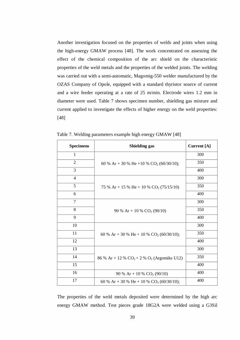
39
Another investigation focused on the properties of welds and joints when using
the high-energy GMAW process [48]. The work concentrated on assessing the
effect of the chemical composition of the arc shield on the characteristic
properties of the weld metals and the properties of the welded joints. The welding
was carried out with a semi-automatic, Magomig-550 welder manufactured by the
OZAS Company of Opole, equipped with a standard thyristor source of current
and a wire feeder operating at a rate of 25 m/min. Electrode wires 1.2 mm in
diameter were used. Table 7 shows specimen number, shielding gas mixture and
current applied to investigate the effects of higher energy on the weld properties:
[48]
Table 7. Welding parameters example high energy GMAW [48]
Specimens Shielding gas Current [A]
1
60 % Ar + 30 % He +10 % CO2 (60/30/10);
300
2 350
3 400
4
75 % Ar + 15 % He + 10 % CO2 (75/15/10)
300
5 350
6 400
7
90 % Ar + 10 % CO2 (90/10)
300
8 350
9 400
10
60 % Ar + 30 % He + 10 % CO2 (60/30/10);
300
11 350
12 400
13
86 % Ar + 12 % CO2 + 2 % O2 (Argomiks U12)
300
14 350
15 400
16 90 % Ar + 10 % CO2 (90/10) 400
17 60 % Ar + 30 % He + 10 % CO2 (60/30/10); 400
The properties of the weld metals deposited were determined by the high arc
energy GMAW method. Test pieces grade 18G2A were welded using a G3Sil
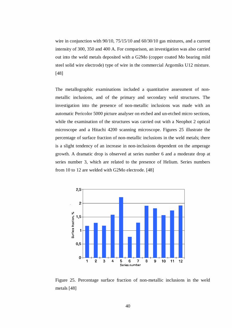
40
wire in conjunction with 90/10, 75/15/10 and 60/30/10 gas mixtures, and a current
intensity of 300, 350 and 400 A. For comparison, an investigation was also carried
out into the weld metals deposited with a G2Mo (copper coated Mo bearing mild
steel solid wire electrode) type of wire in the commercial Argomiks U12 mixture.
[48]
The metallographic examinations included a quantitative assessment of non-
metallic inclusions, and of the primary and secondary weld structures. The
investigation into the presence of non-metallic inclusions was made with an
automatic Pericolor 5000 picture analyser on etched and un-etched micro sections,
while the examination of the structures was carried out with a Neophot 2 optical
microscope and a Hitachi 4200 scanning microscope. Figures 25 illustrate the
percentage of surface fraction of non-metallic inclusions in the weld metals; there
is a slight tendency of an increase in non-inclusions dependent on the amperage
growth. A dramatic drop is observed at series number 6 and a moderate drop at
series number 3, which are related to the presence of Helium. Series numbers
from 10 to 12 are welded with G2Mo electrode. [48]
Figure 25. Percentage surface fraction of non-metallic inclusions in the weld
metals [48]
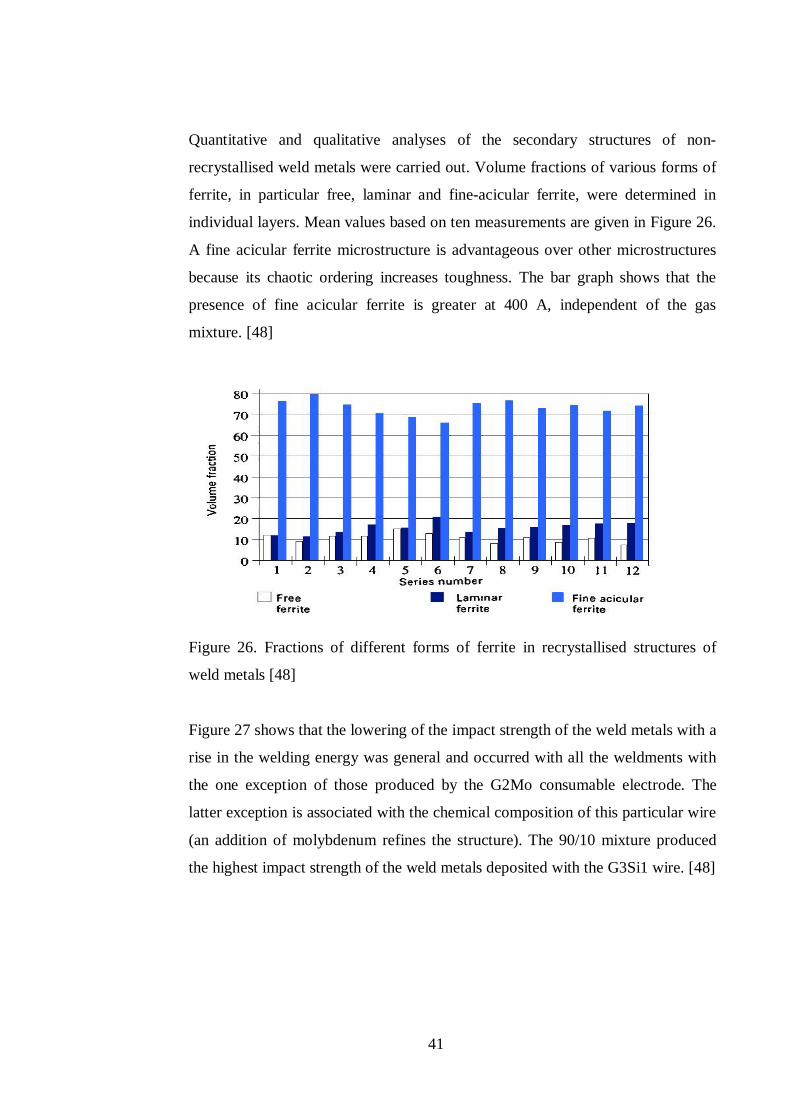
41
Quantitative and qualitative analyses of the secondary structures of non-
recrystallised weld metals were carried out. Volume fractions of various forms of
ferrite, in particular free, laminar and fine-acicular ferrite, were determined in
individual layers. Mean values based on ten measurements are given in Figure 26.
A fine acicular ferrite microstructure is advantageous over other microstructures
because its chaotic ordering increases toughness. The bar graph shows that the
presence of fine acicular ferrite is greater at 400 A, independent of the gas
mixture. [48]
Figure 26. Fractions of different forms of ferrite in recrystallised structures of
weld metals [48]
Figure 27 shows that the lowering of the impact strength of the weld metals with a
rise in the welding energy was general and occurred with all the weldments with
the one exception of those produced by the G2Mo consumable electrode. The
latter exception is associated with the chemical composition of this particular wire
(an addition of molybdenum refines the structure). The 90/10 mixture produced
the highest impact strength of the weld metals deposited with the G3Si1 wire. [48]
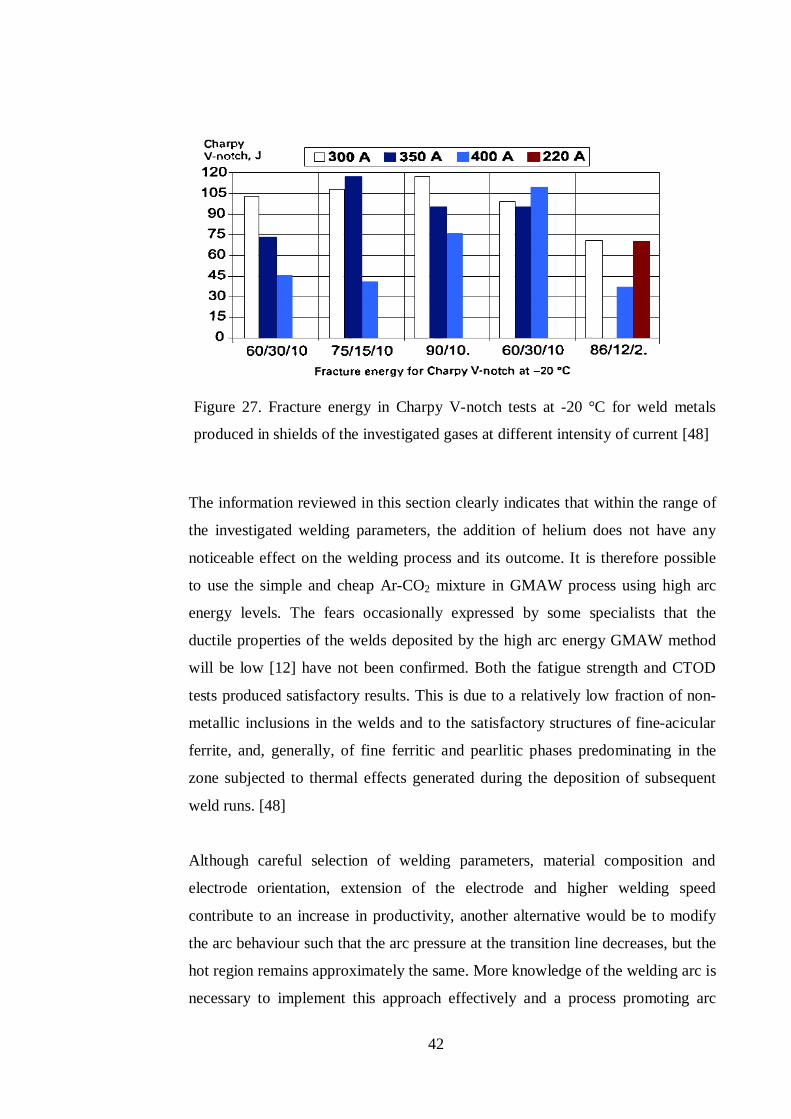
42
Figure 27. Fracture energy in Charpy V-notch tests at -20 °C for weld metals
produced in shields of the investigated gases at different intensity of current [48]
The information reviewed in this section clearly indicates that within the range of
the investigated welding parameters, the addition of helium does not have any
noticeable effect on the welding process and its outcome. It is therefore possible
to use the simple and cheap Ar-CO2 mixture in GMAW process using high arc
energy levels. The fears occasionally expressed by some specialists that the
ductile properties of the welds deposited by the high arc energy GMAW method
will be low [12] have not been confirmed. Both the fatigue strength and CTOD
tests produced satisfactory results. This is due to a relatively low fraction of non-
metallic inclusions in the welds and to the satisfactory structures of fine-acicular
ferrite, and, generally, of fine ferritic and pearlitic phases predominating in the
zone subjected to thermal effects generated during the deposition of subsequent
weld runs. [48]
Although careful selection of welding parameters, material composition and
electrode orientation, extension of the electrode and higher welding speed
contribute to an increase in productivity, another alternative would be to modify
the arc behaviour such that the arc pressure at the transition line decreases, but the
hot region remains approximately the same. More knowledge of the welding arc is
necessary to implement this approach effectively and a process promoting arc

43
control for adaptive pulsed GMAW could have the benefit of an improvement in
the weld quality. [54]
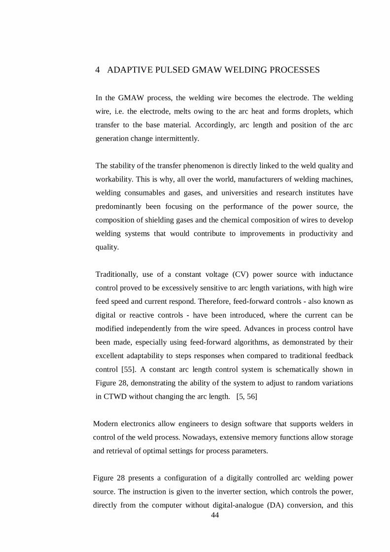
44
4 ADAPTIVE PULSED GMAW WELDING PROCESSES
In the GMAW process, the welding wire becomes the electrode. The welding
wire, i.e. the electrode, melts owing to the arc heat and forms droplets, which
transfer to the base material. Accordingly, arc length and position of the arc
generation change intermittently.
The stability of the transfer phenomenon is directly linked to the weld quality and
workability. This is why, all over the world, manufacturers of welding machines,
welding consumables and gases, and universities and research institutes have
predominantly been focusing on the performance of the power source, the
composition of shielding gases and the chemical composition of wires to develop
welding systems that would contribute to improvements in productivity and
quality.
Traditionally, use of a constant voltage (CV) power source with inductance
control proved to be excessively sensitive to arc length variations, with high wire
feed speed and current respond. Therefore, feed-forward controls - also known as
digital or reactive controls - have been introduced, where the current can be
modified independently from the wire speed. Advances in process control have
been made, especially using feed-forward algorithms, as demonstrated by their
excellent adaptability to steps responses when compared to traditional feedback
control [55]. A constant arc length control system is schematically shown in
Figure 28, demonstrating the ability of the system to adjust to random variations
in CTWD without changing the arc length. [5, 56]
Modern electronics allow engineers to design software that supports welders in
control of the weld process. Nowadays, extensive memory functions allow storage
and retrieval of optimal settings for process parameters.
Figure 28 presents a configuration of a digitally controlled arc welding power
source. The instruction is given to the inverter section, which controls the power,
directly from the computer without digital-analogue (DA) conversion, and this
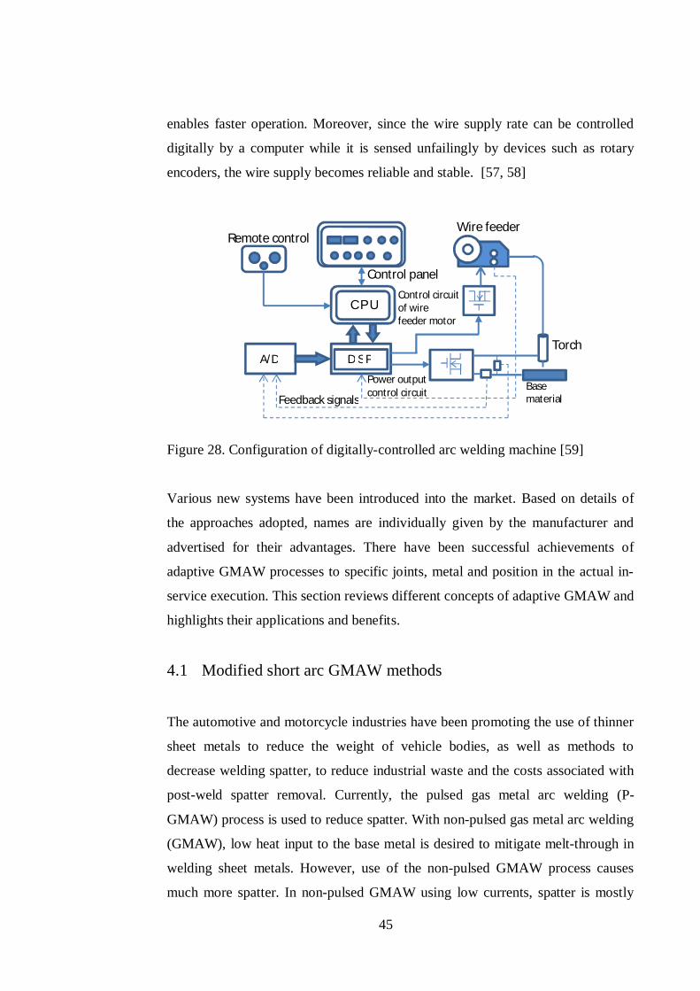
45
enables faster operation. Moreover, since the wire supply rate can be controlled
digitally by a computer while it is sensed unfailingly by devices such as rotary
encoders, the wire supply becomes reliable and stable. [57, 58]
Figure 28. Configuration of digitally-controlled arc welding machine [59]
Various new systems have been introduced into the market. Based on details of
the approaches adopted, names are individually given by the manufacturer and
advertised for their advantages. There have been successful achievements of
adaptive GMAW processes to specific joints, metal and position in the actual in-
service execution. This section reviews different concepts of adaptive GMAW and
highlights their applications and benefits.
4.1 Modified short arc GMAW methods
The automotive and motorcycle industries have been promoting the use of thinner
sheet metals to reduce the weight of vehicle bodies, as well as methods to
decrease welding spatter, to reduce industrial waste and the costs associated with
post-weld spatter removal. Currently, the pulsed gas metal arc welding (P-
GMAW) process is used to reduce spatter. With non-pulsed gas metal arc welding
(GMAW), low heat input to the base metal is desired to mitigate melt-through in
welding sheet metals. However, use of the non-pulsed GMAW process causes
much more spatter. In non-pulsed GMAW using low currents, spatter is mostly
Remote control Wire feeder
Control panel Control circuit of wire feeder motor
Torch
Base material
A/D D S P
Feedback signals
Power output control circuit
C P U
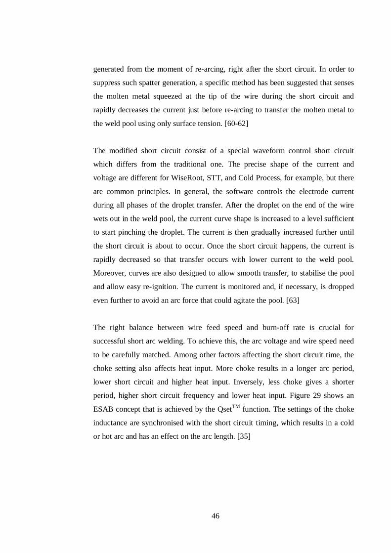
46
generated from the moment of re-arcing, right after the short circuit. In order to
suppress such spatter generation, a specific method has been suggested that senses
the molten metal squeezed at the tip of the wire during the short circuit and
rapidly decreases the current just before re-arcing to transfer the molten metal to
the weld pool using only surface tension. [60-62]
The modified short circuit consist of a special waveform control short circuit
which differs from the traditional one. The precise shape of the current and
voltage are different for WiseRoot, STT, and Cold Process, for example, but there
are common principles. In general, the software controls the electrode current
during all phases of the droplet transfer. After the droplet on the end of the wire
wets out in the weld pool, the current curve shape is increased to a level sufficient
to start pinching the droplet. The current is then gradually increased further until
the short circuit is about to occur. Once the short circuit happens, the current is
rapidly decreased so that transfer occurs with lower current to the weld pool.
Moreover, curves are also designed to allow smooth transfer, to stabilise the pool
and allow easy re-ignition. The current is monitored and, if necessary, is dropped
even further to avoid an arc force that could agitate the pool. [63]
The right balance between wire feed speed and burn-off rate is crucial for
successful short arc welding. To achieve this, the arc voltage and wire speed need
to be carefully matched. Among other factors affecting the short circuit time, the
choke setting also affects heat input. More choke results in a longer arc period,
lower short circuit and higher heat input. Inversely, less choke gives a shorter
period, higher short circuit frequency and lower heat input. Figure 29 shows an
ESAB concept that is achieved by the QsetTM function. The settings of the choke
inductance are synchronised with the short circuit timing, which results in a cold
or hot arc and has an effect on the arc length. [35]
47
Figure 29. Setting of arc frequency by inductance, capability of control of short-
circuit and arcing time [35]
4.2 Modified pulsed GMAW methods
In the past there was little scope for process modification of the pulsed GMAW
method. Notable exceptions were dual power source concepts for dip transfer and
the early introduction of pulsed transfer GMAW using sinusoidal current pulses
[64]. Pulsed GMAW (P-GMAW) provided additional control of the GMAW
process by using a current waveform consisting of a low background level to
maintain the arc and a superimposed pulse current to detach the material. The
objective was to produce spray type projected transfer at mean currents below the
spray transition threshold. The process gave good positional spray performance
and was particularly beneficial in the welding of aluminium alloys and stainless
steel [65, 66]. The main limitation of the process was the power source design
constraint, which meant that pulse frequency was usually a multiple of mains
frequency and the pulse profile and duration were dependent on the fixed power
source design. The introduction of solid state power control meant that power
source statics and dynamics characteristics, and output waveforms could be
varied. Based on the early work of J. Ma [29] it became possible to produce the
drop spray transfer mode discussed above in a controllable and repeatable manner
over a wide current range. Nowadays, structural steel has been added amount
material weldable by P-GMAW.
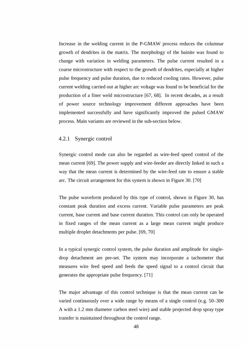
48
Increase in the welding current in the P-GMAW process reduces the columnar
growth of dendrites in the matrix. The morphology of the bainite was found to
change with variation in welding parameters. The pulse current resulted in a
coarse microstructure with respect to the growth of dendrites, especially at higher
pulse frequency and pulse duration, due to reduced cooling rates. However, pulse
current welding carried out at higher arc voltage was found to be beneficial for the
production of a finer weld microstructure [67, 68]. In recent decades, as a result
of power source technology improvement different approaches have been
implemented successfully and have significantly improved the pulsed GMAW
process. Main variants are reviewed in the sub-section below.
4.2.1 Synergic control
Synergic control mode can also be regarded as wire-feed speed control of the
mean current [69]. The power supply and wire-feeder are directly linked in such a
way that the mean current is determined by the wire-feed rate to ensure a stable
arc. The circuit arrangement for this system is shown in Figure 30. [70]
The pulse waveform produced by this type of control, shown in Figure 30, has
constant peak duration and excess current. Variable pulse parameters are peak
current, base current and base current duration. This control can only be operated
in fixed ranges of the mean current as a large mean current might produce
multiple droplet detachments per pulse. [69, 70]
In a typical synergic control system, the pulse duration and amplitude for single-
drop detachment are pre-set. The system may incorporate a tachometer that
measures wire feed speed and feeds the speed signal to a control circuit that
generates the appropriate pulse frequency. [71]
The major advantage of this control technique is that the mean current can be
varied continuously over a wide range by means of a single control (e.g. 50–300
A with a 1.2 mm diameter carbon steel wire) and stable projected drop spray type
transfer is maintained throughout the control range.
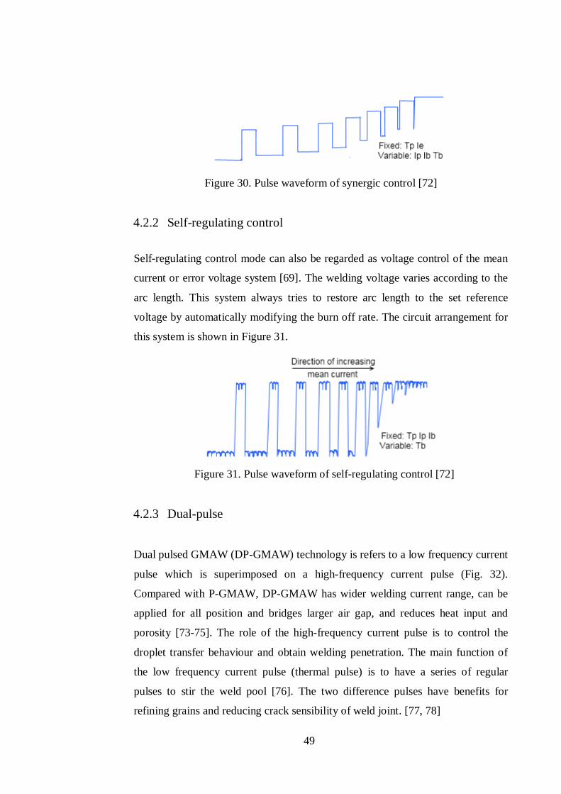
49
Figure 30. Pulse waveform of synergic control [72]
4.2.2 Self-regulating control
Self-regulating control mode can also be regarded as voltage control of the mean
current or error voltage system [69]. The welding voltage varies according to the
arc length. This system always tries to restore arc length to the set reference
voltage by automatically modifying the burn off rate. The circuit arrangement for
this system is shown in Figure 31.
Figure 31. Pulse waveform of self-regulating control [72]
4.2.3 Dual-pulse
Dual pulsed GMAW (DP-GMAW) technology is refers to a low frequency current
pulse which is superimposed on a high-frequency current pulse (Fig. 32).
Compared with P-GMAW, DP-GMAW has wider welding current range, can be
applied for all position and bridges larger air gap, and reduces heat input and
porosity [73-75]. The role of the high-frequency current pulse is to control the
droplet transfer behaviour and obtain welding penetration. The main function of
the low frequency current pulse (thermal pulse) is to have a series of regular
pulses to stir the weld pool [76]. The two difference pulses have benefits for
refining grains and reducing crack sensibility of weld joint. [77, 78]
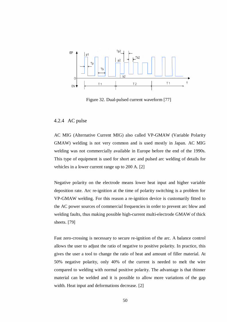
50
Figure 32. Dual-pulsed current waveform [77]
4.2.4 AC pulse
AC MIG (Alternative Current MIG) also called VP-GMAW (Variable Polarity
GMAW) welding is not very common and is used mostly in Japan. AC MIG
welding was not commercially available in Europe before the end of the 1990s.
This type of equipment is used for short arc and pulsed arc welding of details for
vehicles in a lower current range up to 200 A. [2]
Negative polarity on the electrode means lower heat input and higher variable
deposition rate. Arc re-ignition at the time of polarity switching is a problem for
VP-GMAW welding. For this reason a re-ignition device is customarily fitted to
the AC power sources of commercial frequencies in order to prevent arc blow and
welding faults, thus making possible high-current multi-electrode GMAW of thick
sheets. [79]
Fast zero-crossing is necessary to secure re-ignition of the arc. A balance control
allows the user to adjust the ratio of negative to positive polarity. In practice, this
gives the user a tool to change the ratio of heat and amount of filler material. At
50% negative polarity, only 40% of the current is needed to melt the wire
compared to welding with normal positive polarity. The advantage is that thinner
material can be welded and it is possible to allow more variations of the gap
width. Heat input and deformations decrease. [2]
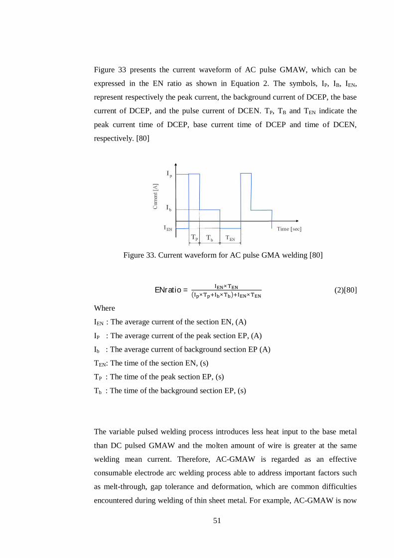
51
Figure 33 presents the current waveform of AC pulse GMAW, which can be
expressed in the EN ratio as shown in Equation 2. The symbols, IP, IB, IEN,
represent respectively the peak current, the background current of DCEP, the base
current of DCEP, and the pulse current of DCEN. TP, TB and TEN indicate the
peak current time of DCEP, base current time of DCEP and time of DCEN,
respectively. [80]
Figure 33. Current waveform for AC pulse GMA welding [80]
ENratio = ×× × ×
(2)[80]
Where
IEN : The average current of the section EN, (A)
IP : The average current of the peak section EP, (A)
Ib : The average current of background section EP (A)
TEN: The time of the section EN, (s)
TP : The time of the peak section EP, (s)
Tb : The time of the background section EP, (s)
The variable pulsed welding process introduces less heat input to the base metal
than DC pulsed GMAW and the molten amount of wire is greater at the same
welding mean current. Therefore, AC-GMAW is regarded as an effective
consumable electrode arc welding process able to address important factors such
as melt-through, gap tolerance and deformation, which are common difficulties
encountered during welding of thin sheet metal. For example, AC-GMAW is now
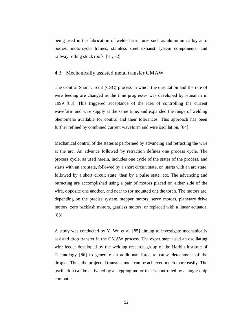
52
being used in the fabrication of welded structures such as aluminium alloy auto
bodies, motorcycle frames, stainless steel exhaust system components, and
railway rolling stock roofs. [81, 82]
4.3 Mechanically assisted metal transfer GMAW
The Control Short Circuit (CSC) process in which the orientation and the rate of
wire feeding are changed as the time progresses was developed by Huisman in
1999 [83]. This triggered acceptance of the idea of controlling the current
waveform and wire supply at the same time, and expanded the range of welding
phenomena available for control and their tolerances. This approach has been
further refined by combined current waveform and wire oscillation. [84]
Mechanical control of the states is performed by advancing and retracting the wire
at the arc. An advance followed by retraction defines one process cycle. The
process cycle, as used herein, includes one cycle of the states of the process, and
starts with an arc state, followed by a short circuit state, or starts with an arc state,
followed by a short circuit state, then by a pulse state, etc. The advancing and
retracting are accomplished using a pair of motors placed on either side of the
wire, opposite one another, and near to (or mounted on) the torch. The motors are,
depending on the precise system, stepper motors, servo motors, planetary drive
motors, zero backlash motors, gearless motors, or replaced with a linear actuator.
[83]
A study was conducted by Y. Wu et al. [85] aiming to investigate mechanically
assisted drop transfer in the GMAW process. The experiment used an oscillating
wire feeder developed by the welding research group of the Harbin Institute of
Technology [86] to generate an additional force to cause detachment of the
droplet. Thus, the projected transfer mode can be achieved much more easily. The
oscillation can be activated by a stepping motor that is controlled by a single-chip
computer.
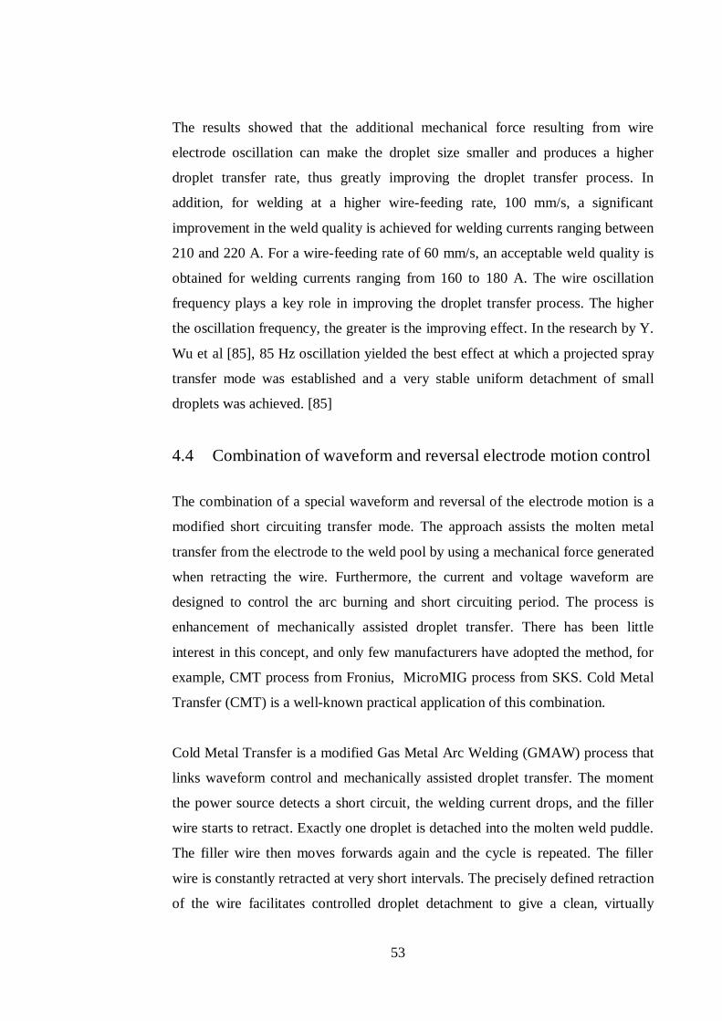
53
The results showed that the additional mechanical force resulting from wire
electrode oscillation can make the droplet size smaller and produces a higher
droplet transfer rate, thus greatly improving the droplet transfer process. In
addition, for welding at a higher wire-feeding rate, 100 mm/s, a significant
improvement in the weld quality is achieved for welding currents ranging between
210 and 220 A. For a wire-feeding rate of 60 mm/s, an acceptable weld quality is
obtained for welding currents ranging from 160 to 180 A. The wire oscillation
frequency plays a key role in improving the droplet transfer process. The higher
the oscillation frequency, the greater is the improving effect. In the research by Y.
Wu et al [85], 85 Hz oscillation yielded the best effect at which a projected spray
transfer mode was established and a very stable uniform detachment of small
droplets was achieved. [85]
4.4 Combination of waveform and reversal electrode motion control
The combination of a special waveform and reversal of the electrode motion is a
modified short circuiting transfer mode. The approach assists the molten metal
transfer from the electrode to the weld pool by using a mechanical force generated
when retracting the wire. Furthermore, the current and voltage waveform are
designed to control the arc burning and short circuiting period. The process is
enhancement of mechanically assisted droplet transfer. There has been little
interest in this concept, and only few manufacturers have adopted the method, for
example, CMT process from Fronius, MicroMIG process from SKS. Cold Metal
Transfer (CMT) is a well-known practical application of this combination.
Cold Metal Transfer is a modified Gas Metal Arc Welding (GMAW) process that
links waveform control and mechanically assisted droplet transfer. The moment
the power source detects a short circuit, the welding current drops, and the filler
wire starts to retract. Exactly one droplet is detached into the molten weld puddle.
The filler wire then moves forwards again and the cycle is repeated. The filler
wire is constantly retracted at very short intervals. The precisely defined retraction
of the wire facilitates controlled droplet detachment to give a clean, virtually
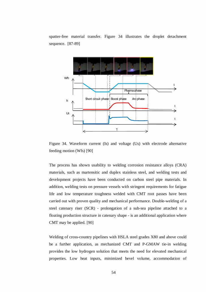
54
spatter-free material transfer. Figure 34 illustrates the droplet detachment
sequence. [87-89]
Figure 34. Waveform current (Is) and voltage (Us) with electrode alternative
feeding motion (Wfs) [90]
The process has shown usability to welding corrosion resistance alloys (CRA)
materials, such as martensitic and duplex stainless steel, and welding tests and
development projects have been conducted on carbon steel pipe materials. In
addition, welding tests on pressure vessels with stringent requirements for fatigue
life and low temperature toughness welded with CMT root passes have been
carried out with proven quality and mechanical performance. Double-welding of a
steel catenary riser (SCR) - prolongation of a sub-sea pipeline attached to a
floating production structure in catenary shape - is an additional application where
CMT may be applied. [90]
Welding of cross-country pipelines with HSLA steel grades X80 and above could
be a further application, as mechanized CMT and P-GMAW tie-in welding
provides the low hydrogen solution that meets the need for elevated mechanical
properties. Low heat inputs, minimized bevel volume, accommodation of
Plasma phase
Short circuit phase Boost phase Arc phase
Wfs
Us
Is
T
t
t
t
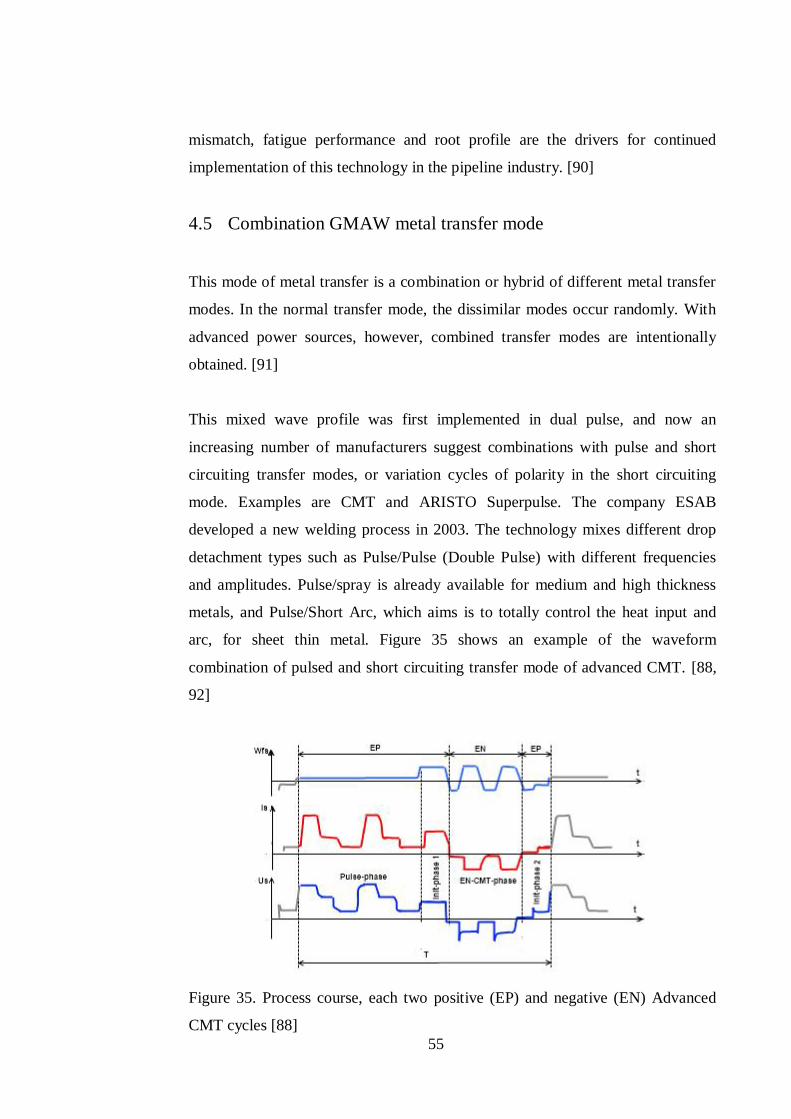
55
mismatch, fatigue performance and root profile are the drivers for continued
implementation of this technology in the pipeline industry. [90]
4.5 Combination GMAW metal transfer mode
This mode of metal transfer is a combination or hybrid of different metal transfer
modes. In the normal transfer mode, the dissimilar modes occur randomly. With
advanced power sources, however, combined transfer modes are intentionally
obtained. [91]
This mixed wave profile was first implemented in dual pulse, and now an
increasing number of manufacturers suggest combinations with pulse and short
circuiting transfer modes, or variation cycles of polarity in the short circuiting
mode. Examples are CMT and ARISTO Superpulse. The company ESAB
developed a new welding process in 2003. The technology mixes different drop
detachment types such as Pulse/Pulse (Double Pulse) with different frequencies
and amplitudes. Pulse/spray is already available for medium and high thickness
metals, and Pulse/Short Arc, which aims is to totally control the heat input and
arc, for sheet thin metal. Figure 35 shows an example of the waveform
combination of pulsed and short circuiting transfer mode of advanced CMT. [88,
92]
Figure 35. Process course, each two positive (EP) and negative (EN) Advanced
CMT cycles [88]
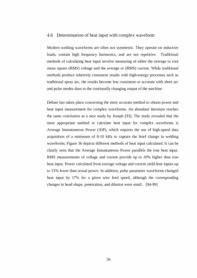
56
4.6 Determination of heat input with complex waveform
Modern welding waveforms are often not symmetric. They operate on inductive
loads, contain high frequency harmonics, and are not repetitive. Traditional
methods of calculating heat input involve measuring of either the average or root
mean square (RMS) voltage and the average or (RMS) current. While traditional
methods produce relatively consistent results with high-energy processes such as
traditional spray arc, the results become less consistent or accurate with short arc
and pulse modes dues to the continually changing output of the machine.
Debate has taken place concerning the most accurate method to obtain power and
heat input measurement for complex waveforms. An abundant literature reaches
the same conclusion as a new study by Joseph [93]. The study revealed that the
most appropriate method to calculate heat input for complex waveforms is
Average Instantaneous Power (AIP), which requires the use of high-speed data
acquisition of a minimum of 8-10 kHz to capture the brief change in welding
waveforms. Figure 36 depicts different methods of heat input calculated. It can be
clearly seen that the Average Instantaneous Power parallels the true heat input.
RMS measurements of voltage and current provide up to 10% higher than true
heat input. Power calculated from average voltage and current yield heat inputs up
to 15% lower than actual power. In addition, pulse parameter waveforms changed
heat input by 17% for a given wire feed speed, although the corresponding
changes in bead shape, penetration, and dilution were small. [94-99]
57
Figure 36. Graph comparing calculated heat input to actual heat input for P-
GMAW [100]
The current trend is to fully integrate complex waveforms in standard codes,
because the welding power source needs to capture data and calculate heat input,
i.e. the trend is to avoid specific data acquisition devices. A new approach as
suggested by ASME Section IX is for power sources that compute complex
waveforms to directly output an energy reading made using instantaneous
measurement and calculation methods. The heat input is calculated by dividing
the energy reading by the length of the weld, as shown in Equations (3) and (4).
[101]
Q(Joules/mm) = ( )( )
(3)
or
Q(Joules/mm) = ( )× ( )( )
(4)
58
5 COMPARISON BETWEEN CONVENTIONAL AND
ADAPTIVE GMAW
Table 8 compares different approaches of the adaptive GMAW process. The
concepts differ depending on the parameters being controlled. The main concerns
are; the electrode extension control, the current polarity control, the waveform
current and voltage control, the electrode reversal control, the combination of
waveform and electrode reversal control, and the combination of different transfer
modes.
Electrode extension significantly improves the melting rate; however, it requires a
high current and it is only applied in automated welding. The variable polarities
overcome difficulties in welding aluminium. With a direct negative electrode, the
melting rate is higher but specific requirements for the zero fast crossing and low
dilution are drawbacks.
The pulse allows better control of droplet transfer, which reduces spatter;
unfortunately, the arc should be long to prevent any unexpected short arc during
metal transfer. When a short circuit is needed, the software controls the
percentage of short circuit occurrence to reduce spatter. Waveform control of the
short circuiting transfer mode reduces spatter and heat input and increases welding
speed. With a reversal electrode, the heat is reduced by a low current at the
electrode pinch. The process needs a special torch, and a special waveform, if
added, results in even lower heat and an increase in welding speed.
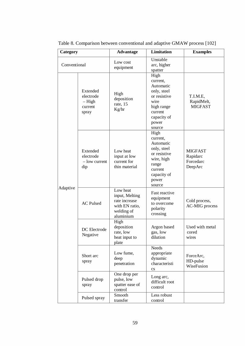
59
Table 8. Comparison between conventional and adaptive GMAW process [102]
Category Advantage Limitation Examples
Conventional Low cost equipment
Unstable arc, higher spatter
Adaptive
Extended electrode – High current spray
High deposition rate, 15 Kg/hr
High current, Automatic only, steel or resistive wire high range current capacity of power source
T.I.M.E, RapidMelt,
MIGFAST
Extended electrode – low current dip
Low heat input at low current for thin material
High current, Automatic only, steel or resistive wire, high range current capacity of power source
MIGFAST Rapidarc Forcedarc DeepArc
AC Pulsed
Low heat input, Melting rate increase with EN ratio, welding of aluminium
Fast reactive equipment to overcome polarity crossing
Cold process, AC-MIG process
DC Electrode Negative
High deposition rate, low heat input to plate
Argon based gas, low dilution
Used with metal cored wires
Short arc spray
Low fume, deep penetration
Needs appropriate dynamic characteristics
ForceArc, HD-pulse WiseFusion
Pulsed drop spray
One drop per pulse, low spatter ease of control
Long arc, difficult root control
Pulsed spray Smooth transfer
Less robust control
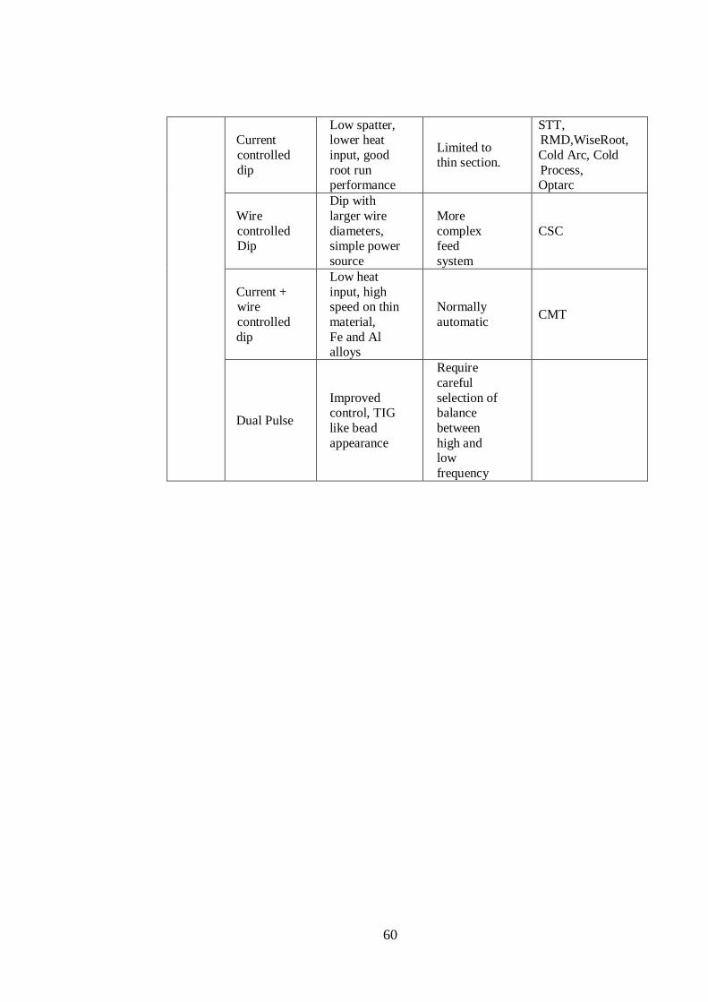
60
Current controlled dip
Low spatter, lower heat input, good root run performance
Limited to thin section.
STT, RMD,WiseRoot, Cold Arc, Cold Process, Optarc
Wire controlled Dip
Dip with larger wire diameters, simple power source
More complex feed system
CSC
Current + wire controlled dip
Low heat input, high speed on thin material, Fe and Al alloys
Normally automatic CMT
Dual Pulse
Improved control, TIG like bead appearance
Require careful selection of balance between high and low frequency
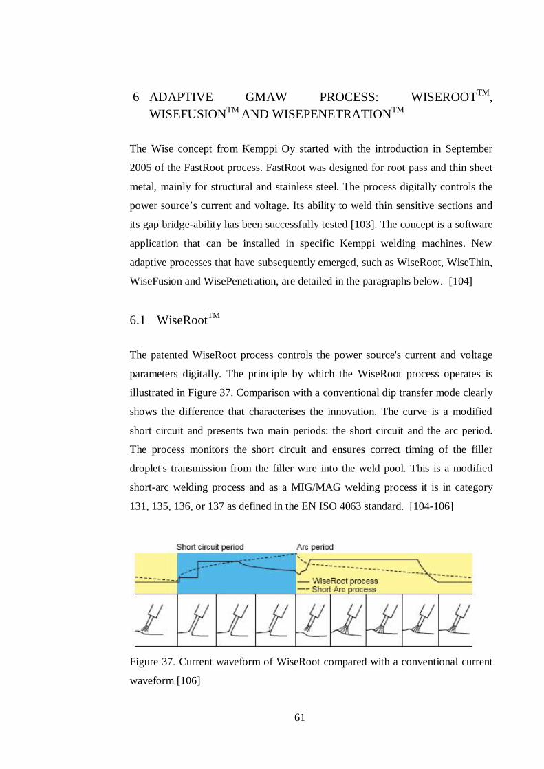
61
6 ADAPTIVE GMAW PROCESS: WISEROOTTM, WISEFUSIONTM AND WISEPENETRATIONTM
The Wise concept from Kemppi Oy started with the introduction in September
2005 of the FastRoot process. FastRoot was designed for root pass and thin sheet
metal, mainly for structural and stainless steel. The process digitally controls the
power source’s current and voltage. Its ability to weld thin sensitive sections and
its gap bridge-ability has been successfully tested [103]. The concept is a software
application that can be installed in specific Kemppi welding machines. New
adaptive processes that have subsequently emerged, such as WiseRoot, WiseThin,
WiseFusion and WisePenetration, are detailed in the paragraphs below. [104]
6.1 WiseRootTM
The patented WiseRoot process controls the power source's current and voltage
parameters digitally. The principle by which the WiseRoot process operates is
illustrated in Figure 37. Comparison with a conventional dip transfer mode clearly
shows the difference that characterises the innovation. The curve is a modified
short circuit and presents two main periods: the short circuit and the arc period.
The process monitors the short circuit and ensures correct timing of the filler
droplet's transmission from the filler wire into the weld pool. This is a modified
short-arc welding process and as a MIG/MAG welding process it is in category
131, 135, 136, or 137 as defined in the EN ISO 4063 standard. [104-106]
Figure 37. Current waveform of WiseRoot compared with a conventional current
waveform [106]
62
In the first upslope stage, there is a short peak in the welding current, during
which the filler material wire contacts the weld pool; the rapid increase of the
current to the desired level generates a so-called pinch force, which allows the
droplet to detach from the tip of the filler wire. The detachment is ensured by
slowly decreasing the current. Once the droplet has been transmitted to the weld
pool, a second stage of increasing current begins and initiates the arc stage. The
control system of the device monitors the droplet detachment moment throughout
the arc. Correctly timed rise and fall of the current guarantees a spatter-free
transfer from the short circuit to the open arc. [105, 106]
The second upslope stage is characterised by a sudden increase that is sustained at
the desired level. The second upslope stage shapes the weld pool and ensures
sufficient penetration in the root pass. After the two upslope stages, one following
upon the other, the current is reduced to the desired base level. Use of a specified
base current level ensures that the next filler droplet will be transmitted during the
next short circuit.
In normal short arc welding, as illustrated in Figure 37, droplet detachment occurs
at a high current value, which depends on the voltage control. After that, the
current slowly decreases, prior to the arc period ending, and the next short circuit
begins. In the WiseRoot process, droplet detachment happens at a low current
value, which results in soft transmission to the weld pool. After that, in the arc
period, the process gives a precisely measured strong boost to the arc and then
rapidly cuts the current to the predetermined level before the next short circuit. A
rapid response and correct timing in the power source control combine with the
correct shape of the current waveform to allow uninterrupted, spatter-free droplet
detachment and transmission into the weld pool. This keeps the arc stable and the
welding process easy to control.
Below is a list of the key benefits of the modified root pass welding process:
[105, 106]
Easy to learn and use.
Fewer spatters than with a normal short arc.
63
Wider root gap makes it possible to use a smaller groove angle and
decrease groove volume.
No need for use of a backing ring.
A highly efficient process: 10 % faster than normal MAG welding, and
three times faster than TIG welding.
Suitable for different position welding
6.2 WiseThinTM
GMAW process has developed such that it is now possible to weld with low heat
input, especially in the short-arc area. For sheet metal welding, low heat input is a
desirable feature and various laser-welding applications have been used for this
purpose. However, lasers have their limitations. As regards sheet metal laser
welding applications, the biggest problems arise from the narrow gap tolerances.
The tolerance window is wider with GMAW processes because they are not so
sensitive to air gap variations. WiseThin is a modified short-arc welding process
and as a GMAW process is in categories 131, 135, 136, or 137 as defined in the
EN ISO 4063 standard. [105, 106]
The principle of the WiseThin process is similar to that of the tailored WiseRoot
process for root pass welding. The difference is that WiseThin is optimised for
sheet metal welding. Kemppi's WiseThin is a tailored GMAW short-arc process
that enables 5–25 % less heat input than with a normal short arc, depending on the
welding case. In welding of high-strength steels, this is of great benefit, because
its microstructure is sensitive to heat and impossible to restore by post weld
treatments. [105, 106]
6.3 WisePenetrationTM
In the manual GMAW process, the stick-out length always varies to some extent,
depending on the welder's skills, and this has an effect on the weld penetration.
Sometimes the welder must increase the stick-out length because of limited
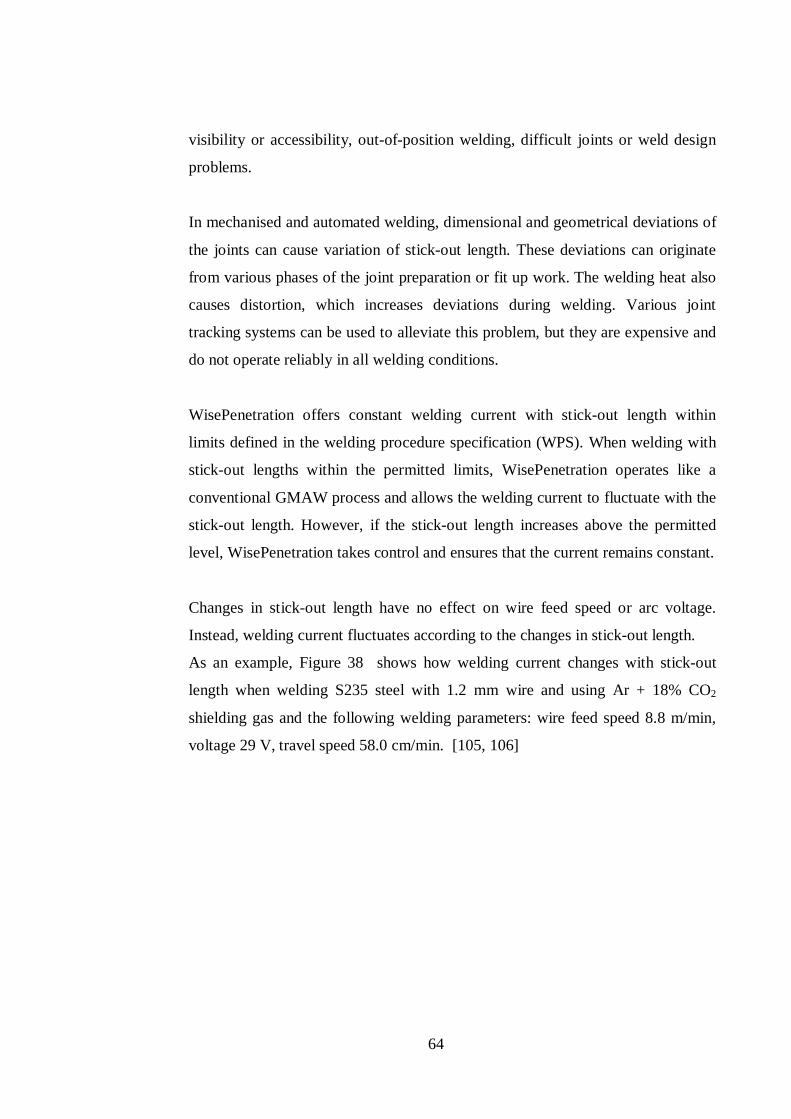
64
visibility or accessibility, out-of-position welding, difficult joints or weld design
problems.
In mechanised and automated welding, dimensional and geometrical deviations of
the joints can cause variation of stick-out length. These deviations can originate
from various phases of the joint preparation or fit up work. The welding heat also
causes distortion, which increases deviations during welding. Various joint
tracking systems can be used to alleviate this problem, but they are expensive and
do not operate reliably in all welding conditions.
WisePenetration offers constant welding current with stick-out length within
limits defined in the welding procedure specification (WPS). When welding with
stick-out lengths within the permitted limits, WisePenetration operates like a
conventional GMAW process and allows the welding current to fluctuate with the
stick-out length. However, if the stick-out length increases above the permitted
level, WisePenetration takes control and ensures that the current remains constant.
Changes in stick-out length have no effect on wire feed speed or arc voltage.
Instead, welding current fluctuates according to the changes in stick-out length.
As an example, Figure 38 shows how welding current changes with stick-out
length when welding S235 steel with 1.2 mm wire and using Ar + 18% CO2
shielding gas and the following welding parameters: wire feed speed 8.8 m/min,
voltage 29 V, travel speed 58.0 cm/min. [105, 106]
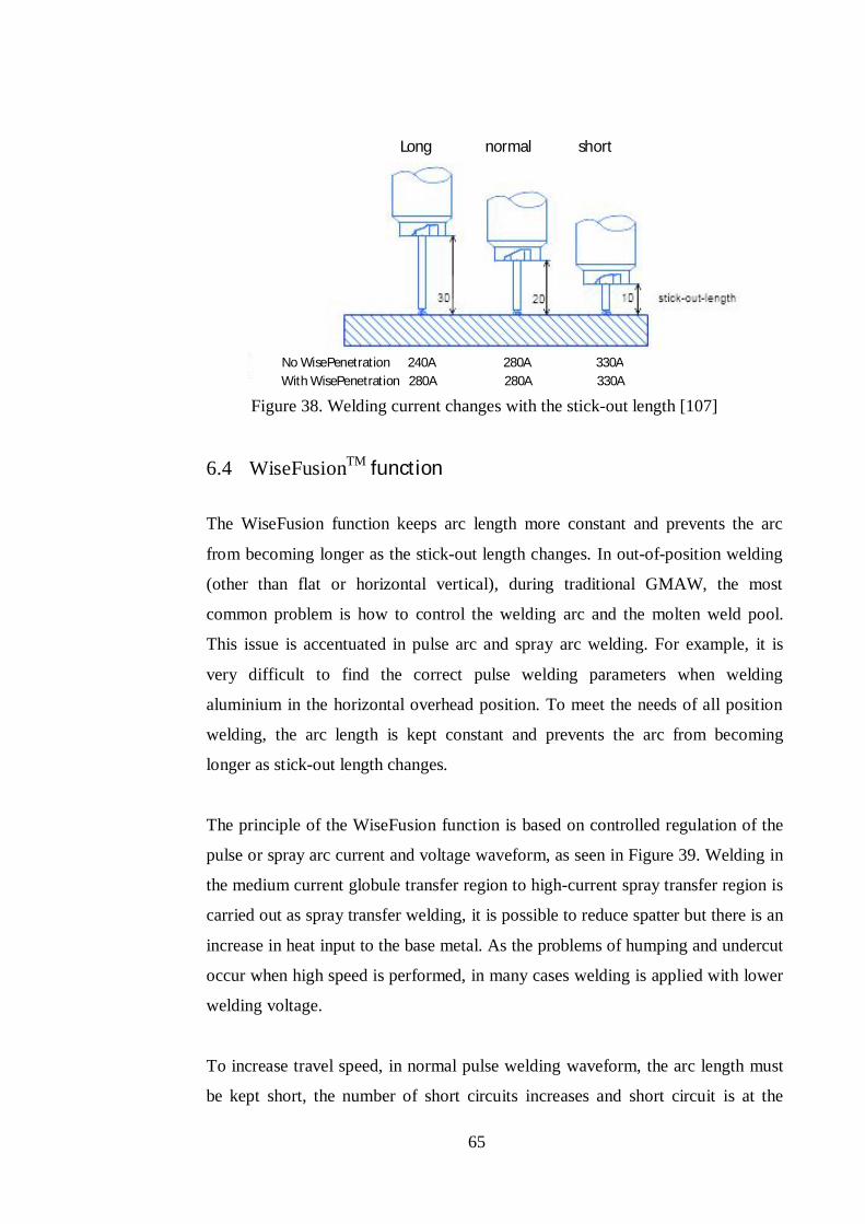
65
Figure 38. Welding current changes with the stick-out length [107]
6.4 WiseFusionTM function
The WiseFusion function keeps arc length more constant and prevents the arc
from becoming longer as the stick-out length changes. In out-of-position welding
(other than flat or horizontal vertical), during traditional GMAW, the most
common problem is how to control the welding arc and the molten weld pool.
This issue is accentuated in pulse arc and spray arc welding. For example, it is
very difficult to find the correct pulse welding parameters when welding
aluminium in the horizontal overhead position. To meet the needs of all position
welding, the arc length is kept constant and prevents the arc from becoming
longer as stick-out length changes.
The principle of the WiseFusion function is based on controlled regulation of the
pulse or spray arc current and voltage waveform, as seen in Figure 39. Welding in
the medium current globule transfer region to high-current spray transfer region is
carried out as spray transfer welding, it is possible to reduce spatter but there is an
increase in heat input to the base metal. As the problems of humping and undercut
occur when high speed is performed, in many cases welding is applied with lower
welding voltage.
To increase travel speed, in normal pulse welding waveform, the arc length must
be kept short, the number of short circuits increases and short circuit is at the
Long normal short
No WisePenetration 240A 280A 330A With WisePenetration 280A 280A 330A
66
pulse peak current. Consequently, short arc length results in stubbing, humping
and spatter. The WiseFusion control short circuit occurrence in the waveforms at
low current, which minimizes spatter and keep the arc focused for optimum
energy. The percentage of short circuit occurrence can be adjusted by selection to
the power source to improve weld quality and efficiency. In pulsed arc
WiseFusion welding, the %-value indicates the number of short circuits in a pulse
sequence. For example, if %-value is 50, half of the droplets detach in open arc
and half of them in short circuit. The power source keeps track of the number of
short circuits so that it remains on the level defined by the WiseFusion %-value.
[105, 106]
Figure 39. Pulse sequence where the filler droplet short-circuits before detaching
[107]
Short circuit occurrence (adjustable in %)
Time (ms)
67
7 EXPERIMENTS
The experiments in this thesis aim to identify advantages from using the adaptive
pulsed GMAW process. Optimal parameters are selected with respect to the small
number of specimens, material cross-section and time available. The section is
divided into four sub-sections: The first sub-section defines the usability targeted
in this study. The second sub-section then presents consumables such as the base
material composition and properties, as well as the filler wire and shielding gas.
The third sub-section describes welding equipment characteristics to understand
the hypothesis of the welding experiment. The last part describes the welding
procedure and includes weld design, weld processes and different tests.
7.1 Usability of the process
One of the primary objectives of this study is to evaluate the usability of adaptive
pulsed GMAW processes. Usability is defined as the ability to produce reliable,
high quality, cost effective welds, over a wide range of gap widths and welding
parameters, even when the welded joint contains gouges or other local defects.
A higher melting rate involves not only a larger quantity of filler material melted,
but also a higher arc heat input, which may have an unfavourable effect on the
mechanical properties of the weld. In welding, it is, therefore, necessary to be
cautious and take into account the chemical composition and the mechanical
properties of the material. [108]
The usability must also be based on the ability of the final weldment to pass non-
destructive as well as destructive, testing with a low reject rate. As with
conventional GMAW methods, high-current arc welding is characterized by a
very deep weld pool depression (gouging region), where the molten metal under
the arc turns into a thin film that flows toward a bulk of liquid (trailing region) at
the rear of the weld pool. This large depression is the direct cause of several weld
pool defects such as humping, undercutting, split bead, parallel humping, and
tunnel porosity. [54]
68
7.2 Materials
The material and filler material must match and present a high degree of
weldability. The driving forces behind the choice of structural steel for this study
is based on their increasing use, often connected to a wish to achieve the best
structural performance at the lowest possible weight and cost. One should
consider, for example, that by using thermo-mechanically controlled process
structural steel, it is possible to reduce the material thickness and deadweight of a
structure, which in turn gives higher payloads.
7.2.1 Base metals
S355 MC structural steel plate is a low-alloy European standard structural steel,
EN 100149 – 2, with a yield strength of 355 MPa, MC refers to thermo-
mechanically rolled (M) and cold formable (C). Careful attention should always
be placed on the specific variation of S355 required if considering substitute
material. S355 MC is very widely used and typical applications include:
Structural steel works: bridge components, and components for offshore
structures
Power plants
Mining and earth-moving equipment
Load-handling equipment
Wind tower components
Table 9 and 10 present respectively the chemical and tensile properties of
S355MC .
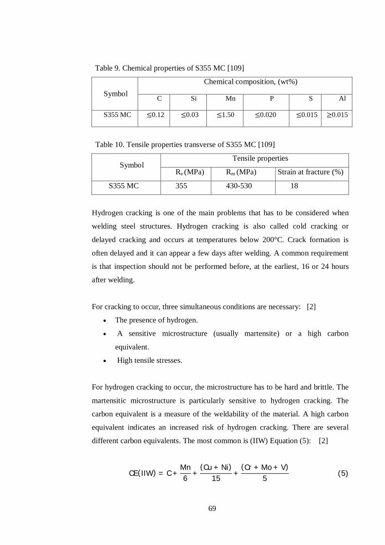
69
Table 9. Chemical properties of S355 MC [109]
Symbol Chemical composition, (wt%)
C Si Mn P S Al
S355 MC 0.12 0.03 1.50 0.020 0.015 0.015
Table 10. Tensile properties transverse of S355 MC [109]
Symbol Tensile properties
Re (MPa) Rm (MPa) Strain at fracture (%)
S355 MC 355 430-530 18
Hydrogen cracking is one of the main problems that has to be considered when
welding steel structures. Hydrogen cracking is also called cold cracking or
delayed cracking and occurs at temperatures below 200°C. Crack formation is
often delayed and it can appear a few days after welding. A common requirement
is that inspection should not be performed before, at the earliest, 16 or 24 hours
after welding.
For cracking to occur, three simultaneous conditions are necessary: [2]
The presence of hydrogen.
A sensitive microstructure (usually martensite) or a high carbon
equivalent.
High tensile stresses.
For hydrogen cracking to occur, the microstructure has to be hard and brittle. The
martensitic microstructure is particularly sensitive to hydrogen cracking. The
carbon equivalent is a measure of the weldability of the material. A high carbon
equivalent indicates an increased risk of hydrogen cracking. There are several
different carbon equivalents. The most common is (IIW) Equation (5): [2]
CE(IIW) = C +Mn6 +
(Cu + Ni)15 +
(Cr + Mo + V)5 (5)
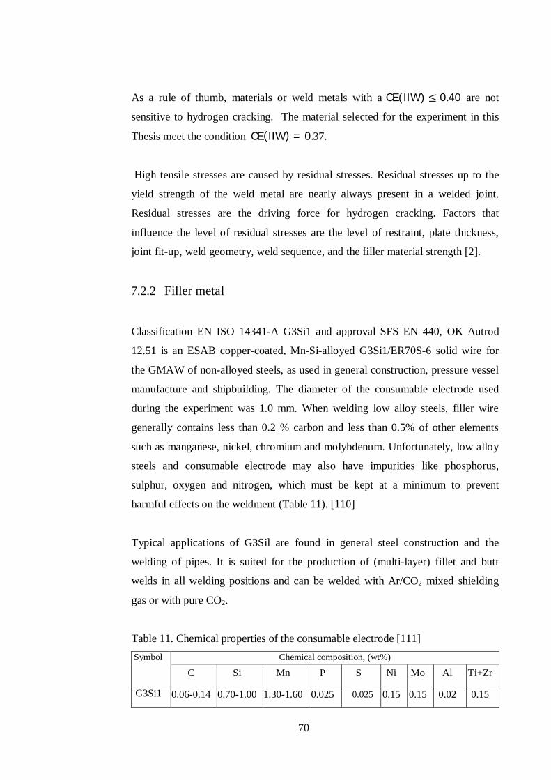
70
As a rule of thumb, materials or weld metals with a CE(IIW) 0.40 are not
sensitive to hydrogen cracking. The material selected for the experiment in this
Thesis meet the condition CE(IIW) = 0.37.
High tensile stresses are caused by residual stresses. Residual stresses up to the
yield strength of the weld metal are nearly always present in a welded joint.
Residual stresses are the driving force for hydrogen cracking. Factors that
influence the level of residual stresses are the level of restraint, plate thickness,
joint fit-up, weld geometry, weld sequence, and the filler material strength [2].
7.2.2 Filler metal
Classification EN ISO 14341-A G3Si1 and approval SFS EN 440, OK Autrod
12.51 is an ESAB copper-coated, Mn-Si-alloyed G3Si1/ER70S-6 solid wire for
the GMAW of non-alloyed steels, as used in general construction, pressure vessel
manufacture and shipbuilding. The diameter of the consumable electrode used
during the experiment was 1.0 mm. When welding low alloy steels, filler wire
generally contains less than 0.2 % carbon and less than 0.5% of other elements
such as manganese, nickel, chromium and molybdenum. Unfortunately, low alloy
steels and consumable electrode may also have impurities like phosphorus,
sulphur, oxygen and nitrogen, which must be kept at a minimum to prevent
harmful effects on the weldment (Table 11). [110]
Typical applications of G3Sil are found in general steel construction and the
welding of pipes. It is suited for the production of (multi-layer) fillet and butt
welds in all welding positions and can be welded with Ar/CO2 mixed shielding
gas or with pure CO2.
Table 11. Chemical properties of the consumable electrode [111] Symbol
Chemical composition, (wt%)
C Si Mn P S Ni Mo Al Ti+Zr
G3Si1 0.06-0.14 0.70-1.00 1.30-1.60 0.025 0.025 0.15 0.15 0.02 0.15
71
7.2.3 Shielding gas
Argon is one of the most popular shielding gases, thanks to its suitable properties.
As an inert gas, it has no chemical interaction with other materials. CO2, or a
small amount of oxygen, improve the welding properties, especially for short arc
welding. A content of up to 20% CO2 improves the penetration (limits the risk of
lack of fusion) while 5-8% will give reduced spatter. Therefore, a mixture of 82%
Argon and 18% CO2 was selected for the experiment. [1, 6, 15]
7.3 Experimental set-up
Figure 40 presents the welding setting of the workstation. The set-up used during
the experiment included a gas regulator, welding machine, a support torch
mechanized unit, a flexible fume extractor and workpiece support, and fixtures.
The power source characteristic and electrode filler wire were read on the
machine rating data plate.
The power source was FastMIG 450 from Kemppi Oy, which is digitally
controlled multi-process equipment. FastMIG 450 can be shifted from synergic
GMAW to synergic pulsed or Wise GMAW processes. The Wise concept
software was installed in the equipment used during the experiment. The
indication on the rating plate showed the International and European Standard
IEC/EN 60974-1-5-10 class and specifies demands on power sources regarding
electrical safety. The enclosure class is IP 23 S and the power source rating is
determined by its duty cycle, which indicates for what proportion of a period of
ten minutes that the power source can be operated at the specified load. 450 A at
60 % duty factor, means that the power source can supply 450 A for 6 minutes in
every ten minutes indefinitely without overheating.
According to the wire feeder speciation unit, it is designed with respect to EC/EN
60974-5-10 JB/T 9533-1999 with 550 A of 60 % duty. The range of wire feed
speed varies from 1 to 25 m/min.
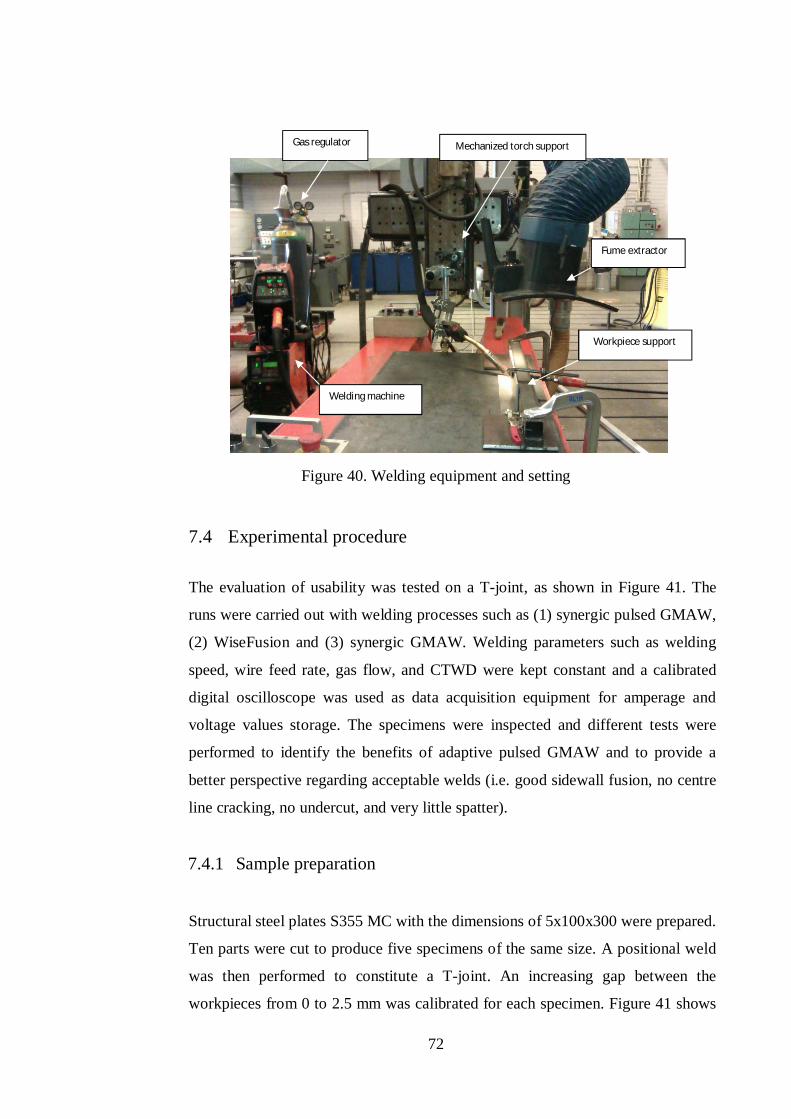
72
Figure 40. Welding equipment and setting
7.4 Experimental procedure
The evaluation of usability was tested on a T-joint, as shown in Figure 41. The
runs were carried out with welding processes such as (1) synergic pulsed GMAW,
(2) WiseFusion and (3) synergic GMAW. Welding parameters such as welding
speed, wire feed rate, gas flow, and CTWD were kept constant and a calibrated
digital oscilloscope was used as data acquisition equipment for amperage and
voltage values storage. The specimens were inspected and different tests were
performed to identify the benefits of adaptive pulsed GMAW and to provide a
better perspective regarding acceptable welds (i.e. good sidewall fusion, no centre
line cracking, no undercut, and very little spatter).
7.4.1 Sample preparation
Structural steel plates S355 MC with the dimensions of 5x100x300 were prepared.
Ten parts were cut to produce five specimens of the same size. A positional weld
was then performed to constitute a T-joint. An increasing gap between the
workpieces from 0 to 2.5 mm was calibrated for each specimen. Figure 41 shows
Fume extractor
Gas regulator Mechanized torch support
Welding machine
Workpiece support
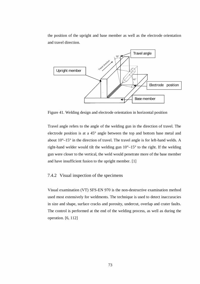
73
the position of the upright and base member as well as the electrode orientation
and travel direction.
Figure 41. Welding design and electrode orientation in horizontal position
Travel angle refers to the angle of the welding gun in the direction of travel. The
electrode position is at a 45° angle between the top and bottom base metal and
about 10°–15° in the direction of travel. The travel angle is for left-hand welds. A
right-hand welder would tilt the welding gun 10°–15° to the right. If the welding
gun were closer to the vertical, the weld would penetrate more of the base member
and have insufficient fusion to the upright member. [1]
7.4.2 Visual inspection of the specimens
Visual examination (VT) SFS-EN 970 is the non-destructive examination method
used most extensively for weldments. The technique is used to detect inaccuracies
in size and shape, surface cracks and porosity, undercut, overlap and crater faults.
The control is performed at the end of the welding process, as well as during the
operation. [6, 112]
Travel angle
Electrode position angle
Base member
Upright member
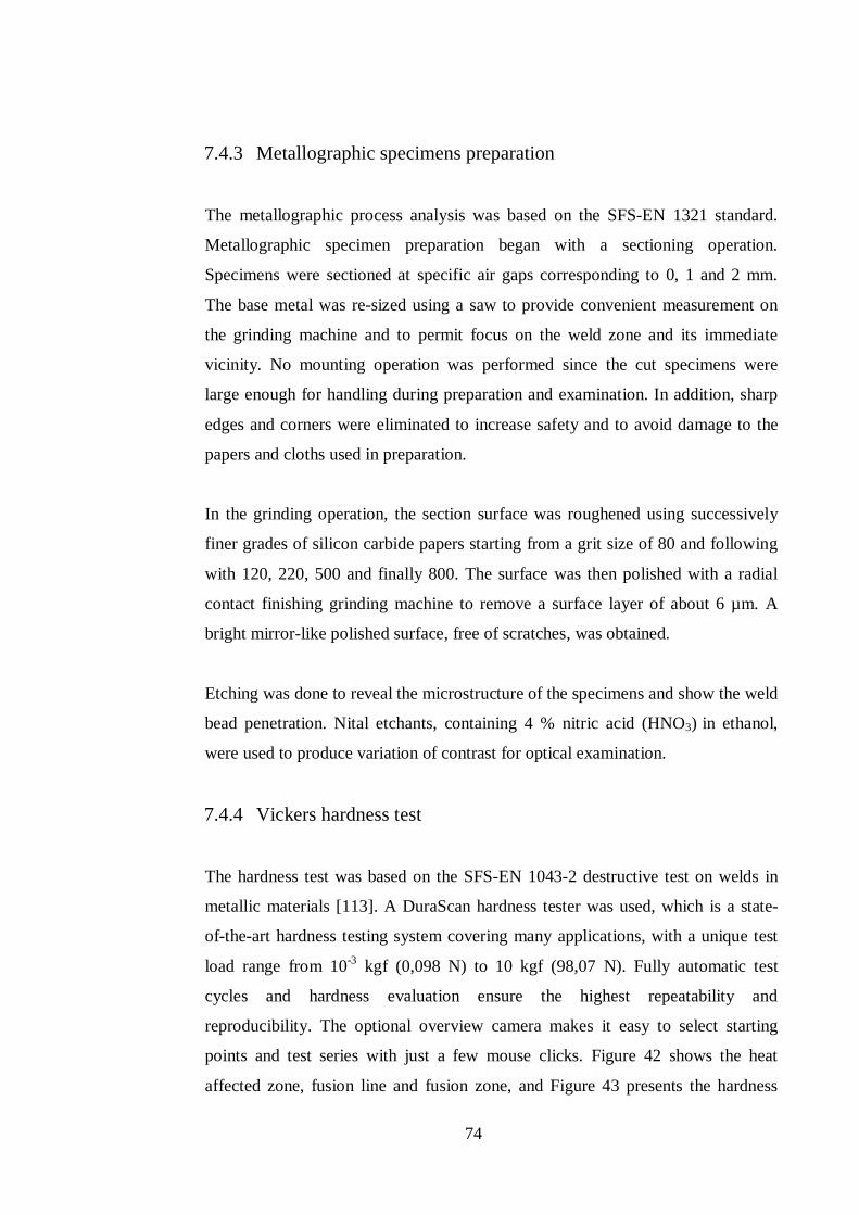
74
7.4.3 Metallographic specimens preparation
The metallographic process analysis was based on the SFS-EN 1321 standard.
Metallographic specimen preparation began with a sectioning operation.
Specimens were sectioned at specific air gaps corresponding to 0, 1 and 2 mm.
The base metal was re-sized using a saw to provide convenient measurement on
the grinding machine and to permit focus on the weld zone and its immediate
vicinity. No mounting operation was performed since the cut specimens were
large enough for handling during preparation and examination. In addition, sharp
edges and corners were eliminated to increase safety and to avoid damage to the
papers and cloths used in preparation.
In the grinding operation, the section surface was roughened using successively
finer grades of silicon carbide papers starting from a grit size of 80 and following
with 120, 220, 500 and finally 800. The surface was then polished with a radial
contact finishing grinding machine to remove a surface layer of about 6 µm. A
bright mirror-like polished surface, free of scratches, was obtained.
Etching was done to reveal the microstructure of the specimens and show the weld
bead penetration. Nital etchants, containing 4 % nitric acid (HNO3) in ethanol,
were used to produce variation of contrast for optical examination.
7.4.4 Vickers hardness test
The hardness test was based on the SFS-EN 1043-2 destructive test on welds in
metallic materials [113]. A DuraScan hardness tester was used, which is a state-
of-the-art hardness testing system covering many applications, with a unique test
load range from 10-3 kgf (0,098 N) to 10 kgf (98,07 N). Fully automatic test
cycles and hardness evaluation ensure the highest repeatability and
reproducibility. The optional overview camera makes it easy to select starting
points and test series with just a few mouse clicks. Figure 42 shows the heat
affected zone, fusion line and fusion zone, and Figure 43 presents the hardness
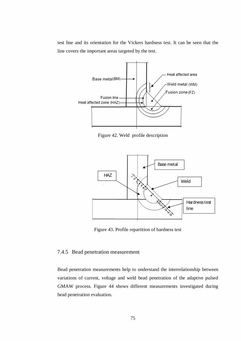
75
test line and its orientation for the Vickers hardness test. It can be seen that the
line covers the important areas targeted by the test.
Figure 42. Weld profile description
Figure 43. Profile repartition of hardness test
7.4.5 Bead penetration measurement
Bead penetration measurements help to understand the interrelationship between
variations of current, voltage and weld bead penetration of the adaptive pulsed
GMAW process. Figure 44 shows different measurements investigated during
bead penetration evaluation.
Base metal
Hardness test line
Weld HAZ
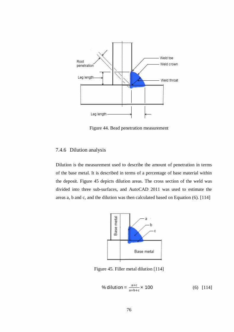
76
Figure 44. Bead penetration measurement
7.4.6 Dilution analysis
Dilution is the measurement used to describe the amount of penetration in terms
of the base metal. It is described in terms of a percentage of base material within
the deposit. Figure 45 depicts dilution areas. The cross section of the weld was
divided into three sub-surfaces, and AutoCAD 2011 was used to estimate the
areas a, b and c, and the dilution was then calculated based on Equation (6). [114]
Figure 45. Filler metal dilution [114]
% dilution = × 100 (6) [114]
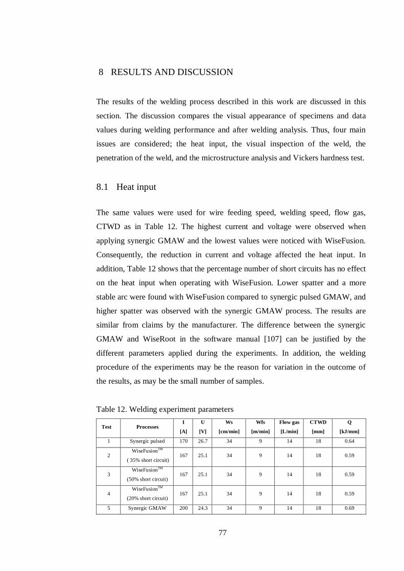
77
8 RESULTS AND DISCUSSION
The results of the welding process described in this work are discussed in this
section. The discussion compares the visual appearance of specimens and data
values during welding performance and after welding analysis. Thus, four main
issues are considered; the heat input, the visual inspection of the weld, the
penetration of the weld, and the microstructure analysis and Vickers hardness test.
8.1 Heat input
The same values were used for wire feeding speed, welding speed, flow gas,
CTWD as in Table 12. The highest current and voltage were observed when
applying synergic GMAW and the lowest values were noticed with WiseFusion.
Consequently, the reduction in current and voltage affected the heat input. In
addition, Table 12 shows that the percentage number of short circuits has no effect
on the heat input when operating with WiseFusion. Lower spatter and a more
stable arc were found with WiseFusion compared to synergic pulsed GMAW, and
higher spatter was observed with the synergic GMAW process. The results are
similar from claims by the manufacturer. The difference between the synergic
GMAW and WiseRoot in the software manual [107] can be justified by the
different parameters applied during the experiments. In addition, the welding
procedure of the experiments may be the reason for variation in the outcome of
the results, as may be the small number of samples.
Table 12. Welding experiment parameters
Test Processes I
[A]
U
[V]
Ws
[cm/min]
Wfs
[m/min]
Flow gas
[L/min]
CTWD
[mm]
Q
[kJ/mm]
1 Synergic pulsed 170 26.7 34 9 14 18 0.64
2 WiseFusionTM
( 35% short circuit) 167 25.1 34 9 14 18 0.59
3 WiseFusionTM
(50% short circuit) 167 25.1 34 9 14 18 0.59
4 WiseFusionTM
(20% short circuit) 167 25.1 34 9 14 18 0.59
5 Synergic GMAW 200 24.3 34 9 14 18 0.69
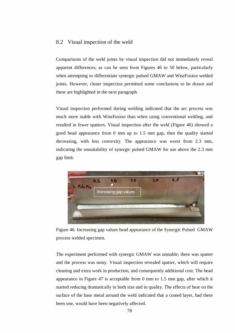
78
8.2 Visual inspection of the weld
Comparisons of the weld joints by visual inspection did not immediately reveal
apparent differences, as can be seen from Figures 46 to 50 below, particularly
when attempting to differentiate synergic pulsed GMAW and WiseFusion welded
joints. However, closer inspection permitted some conclusions to be drawn and
these are highlighted in the next paragraph.
Visual inspection performed during welding indicated that the arc process was
much more stable with WiseFusion than when using conventional welding, and
resulted in fewer spatters. Visual inspection after the weld (Figure 46) showed a
good bead appearance from 0 mm up to 1.5 mm gap, then the quality started
decreasing, with less convexity. The appearance was worst from 2.3 mm,
indicating the unsuitability of synergic pulsed GMAW for use above the 2.3 mm
gap limit.
Figure 46. Increasing gap values bead appearance of the Synergic Pulsed GMAW
process welded specimen.
The experiment performed with synergic GMAW was unstable; there was spatter
and the process was noisy. Visual inspection revealed spatter, which will require
cleaning and extra work in production, and consequently additional cost. The bead
appearance in Figure 47 is acceptable from 0 mm to 1.5 mm gap, after which it
started reducing dramatically in both size and in quality. The effects of heat on the
surface of the base metal around the weld indicated that a coated layer, had there
been one, would have been negatively affected.
Increasing gap values
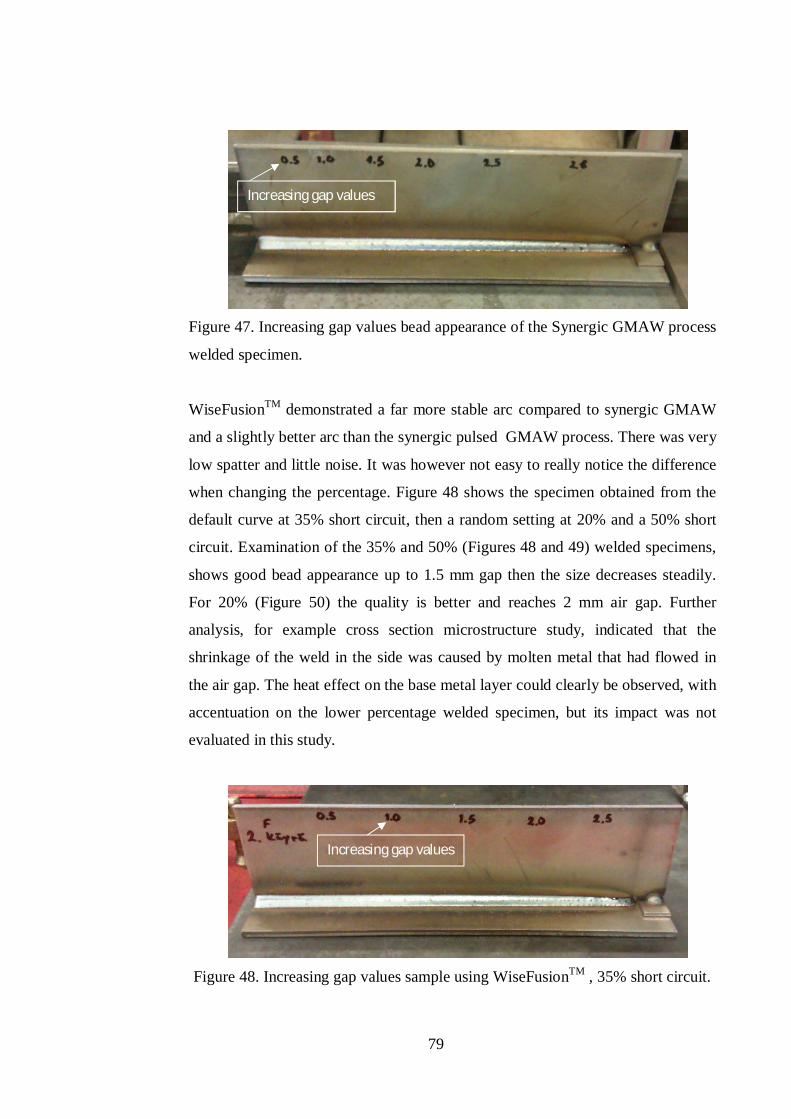
79
Figure 47. Increasing gap values bead appearance of the Synergic GMAW process
welded specimen.
WiseFusionTM demonstrated a far more stable arc compared to synergic GMAW
and a slightly better arc than the synergic pulsed GMAW process. There was very
low spatter and little noise. It was however not easy to really notice the difference
when changing the percentage. Figure 48 shows the specimen obtained from the
default curve at 35% short circuit, then a random setting at 20% and a 50% short
circuit. Examination of the 35% and 50% (Figures 48 and 49) welded specimens,
shows good bead appearance up to 1.5 mm gap then the size decreases steadily.
For 20% (Figure 50) the quality is better and reaches 2 mm air gap. Further
analysis, for example cross section microstructure study, indicated that the
shrinkage of the weld in the side was caused by molten metal that had flowed in
the air gap. The heat effect on the base metal layer could clearly be observed, with
accentuation on the lower percentage welded specimen, but its impact was not
evaluated in this study.
Figure 48. Increasing gap values sample using WiseFusionTM , 35% short circuit.
Increasing gap values
Increasing gap values
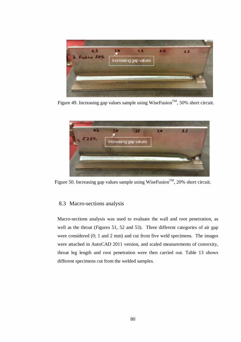
80
Figure 49. Increasing gap values sample using WiseFusionTM, 50% short circuit.
Figure 50. Increasing gap values sample using WiseFusionTM, 20% short circuit.
8.3 Macro-sections analysis
Macro-sections analysis was used to evaluate the wall and root penetration, as
well as the throat (Figures 51, 52 and 53). Three different categories of air gap
were considered (0; 1 and 2 mm) and cut from five weld specimens. The images
were attached in AutoCAD 2011 version, and scaled measurements of convexity,
throat leg length and root penetration were then carried out. Table 13 shows
different specimens cut from the welded samples.
Increasing gap values
Increasing gap values
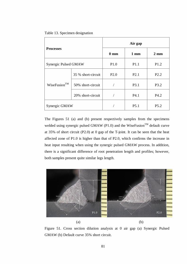
81
Table 13. Specimen designation
Processes Air gap
0 mm 1 mm 2 mm
Synergic Pulsed GMAW P1.0 P1.1 P1.2
WiseFusionTM
35 % short-circuit P2.0 P2.1 P2.2
50% short-circuit / P3.1 P3.2
20% short-circuit / P4.1 P4.2
Synergic GMAW / P5.1 P5.2
The Figures 51 (a) and (b) present respectively samples from the specimens
welded using synergic pulsed GMAW (P1.0) and the WiseFusionTM default curve
at 35% of short circuit (P2.0) at 0 gap of the T-joint. It can be seen that the heat
affected zone of P1.0 is higher than that of P2.0, which confirms the increase in
heat input resulting when using the synergic pulsed GMAW process. In addition,
there is a significant difference of root penetration length and profiles; however,
both samples present quite similar legs length.
(a) (b)
Figure 51. Cross section dilution analysis at 0 air gap (a) Synergic Pulsed
GMAW (b) Default curve 35% short circuit.
P1.0 P2.0
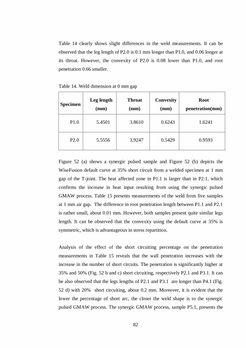
82
Table 14 clearly shows slight differences in the weld measurements. It can be
observed that the leg length of P2.0 is 0.1 mm longer than P1.0, and 0.06 longer at
its throat. However, the convexity of P2.0 is 0.08 lower than P1.0, and root
penetration 0.66 smaller.
Table 14. Weld dimension at 0 mm gap
Specimen Leg length
(mm)
Throat
(mm)
Convexity
(mm)
Root
penetration(mm)
P1.0 5.4501 3.8610 0.6243 1.6241
P2.0 5.5556 3.9247 0.5429 0.9593
Figure 52 (a) shows a synergic pulsed sample and Figure 52 (b) depicts the
WiseFusion default curve at 35% short circuit from a welded specimen at 1 mm
gap of the T-joint. The heat affected zone in P1.1 is larger than in P2.1, which
confirms the increase in heat input resulting from using the synergic pulsed
GMAW process. Table 15 presents measurements of the weld from five samples
at 1 mm air gap. The difference in root penetration length between P1.1 and P2.1
is rather small, about 0.01 mm. However, both samples present quite similar legs
length. It can be observed that the convexity using the default curve at 35% is
symmetric, which is advantageous in stress repartition.
Analysis of the effect of the short circuiting percentage on the penetration
measurements in Table 15 reveals that the wall penetration increases with the
increase in the number of short circuits. The penetration is significantly higher at
35% and 50% (Fig. 52 b and c) short circuiting, respectively P2.1 and P3.1. It can
be also observed that the legs lengths of P2.1 and P3.1 are longer than P4.1 (Fig.
52 d) with 20% short circuiting, about 0.2 mm. Moreover, it is evident that the
lower the percentage of short arc, the closer the weld shape is to the synergic
pulsed GMAW process. The synergic GMAW process, sample P5.1, presents the
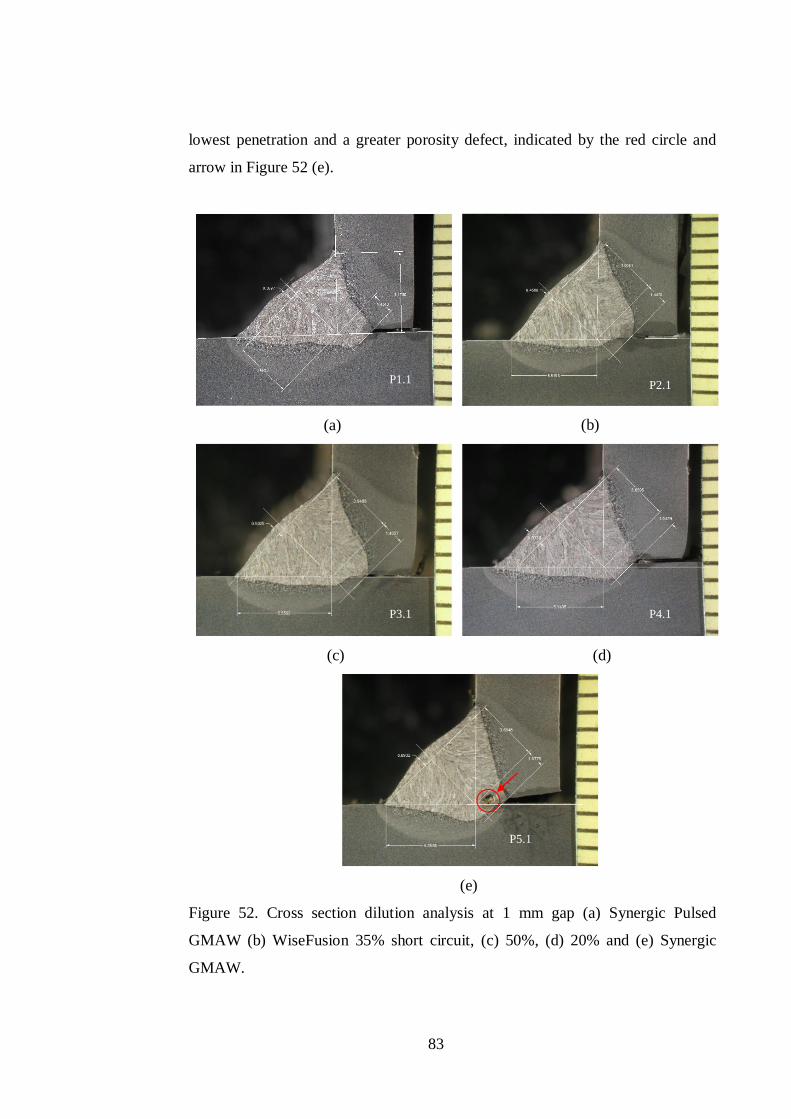
83
lowest penetration and a greater porosity defect, indicated by the red circle and
arrow in Figure 52 (e).
(a) (b)
(c) (d)
(e)
Figure 52. Cross section dilution analysis at 1 mm gap (a) Synergic Pulsed
GMAW (b) WiseFusion 35% short circuit, (c) 50%, (d) 20% and (e) Synergic
GMAW.
P1.1 P2.1
P3.1 P4.1
P5.1
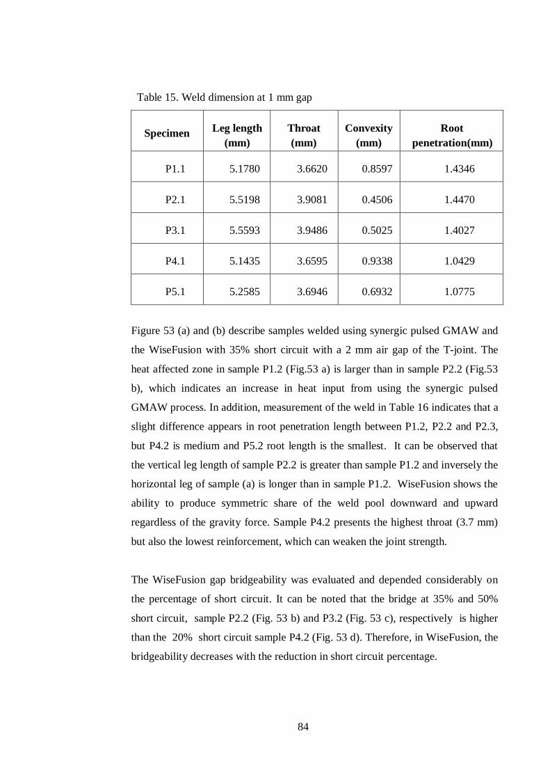
84
Table 15. Weld dimension at 1 mm gap
Specimen Leg length (mm)
Throat (mm)
Convexity (mm)
Root penetration(mm)
P1.1 5.1780 3.6620 0.8597 1.4346
P2.1 5.5198 3.9081 0.4506 1.4470
P3.1 5.5593 3.9486 0.5025 1.4027
P4.1 5.1435 3.6595 0.9338 1.0429
P5.1 5.2585 3.6946 0.6932 1.0775
Figure 53 (a) and (b) describe samples welded using synergic pulsed GMAW and
the WiseFusion with 35% short circuit with a 2 mm air gap of the T-joint. The
heat affected zone in sample P1.2 (Fig.53 a) is larger than in sample P2.2 (Fig.53
b), which indicates an increase in heat input from using the synergic pulsed
GMAW process. In addition, measurement of the weld in Table 16 indicates that a
slight difference appears in root penetration length between P1.2, P2.2 and P2.3,
but P4.2 is medium and P5.2 root length is the smallest. It can be observed that
the vertical leg length of sample P2.2 is greater than sample P1.2 and inversely the
horizontal leg of sample (a) is longer than in sample P1.2. WiseFusion shows the
ability to produce symmetric share of the weld pool downward and upward
regardless of the gravity force. Sample P4.2 presents the highest throat (3.7 mm)
but also the lowest reinforcement, which can weaken the joint strength.
The WiseFusion gap bridgeability was evaluated and depended considerably on
the percentage of short circuit. It can be noted that the bridge at 35% and 50%
short circuit, sample P2.2 (Fig. 53 b) and P3.2 (Fig. 53 c), respectively is higher
than the 20% short circuit sample P4.2 (Fig. 53 d). Therefore, in WiseFusion, the
bridgeability decreases with the reduction in short circuit percentage.
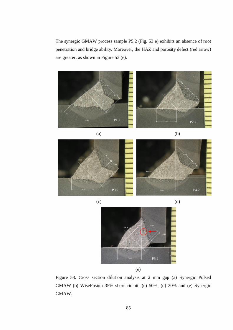
85
The synergic GMAW process sample P5.2 (Fig. 53 e) exhibits an absence of root
penetration and bridge ability. Moreover, the HAZ and porosity defect (red arrow)
are greater, as shown in Figure 53 (e).
(a) (b)
(c) (d)
(e)
Figure 53. Cross section dilution analysis at 2 mm gap (a) Synergic Pulsed
GMAW (b) WiseFusion 35% short circuit, (c) 50%, (d) 20% and (e) Synergic
GMAW.
P1.2 P2.2
P3.2 P4.2
P5.2
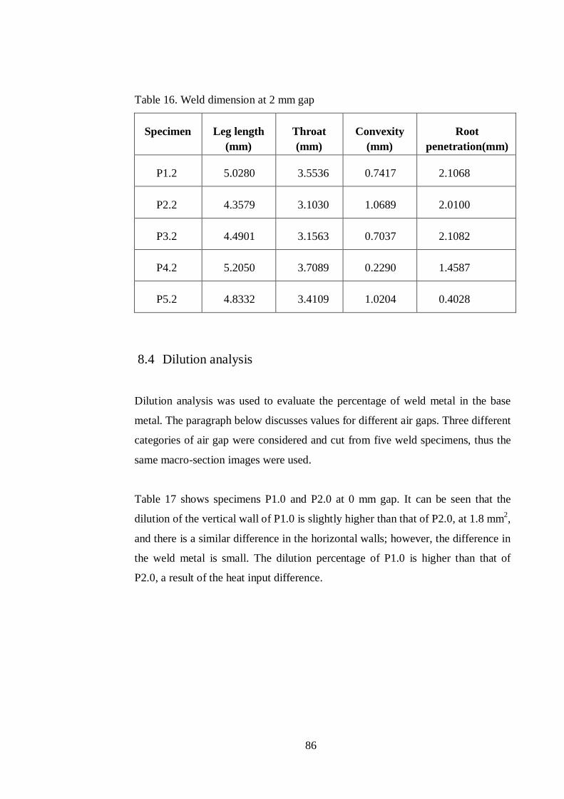
86
Table 16. Weld dimension at 2 mm gap
Specimen Leg length (mm)
Throat (mm)
Convexity (mm)
Root penetration(mm)
P1.2 5.0280 3.5536 0.7417 2.1068
P2.2 4.3579 3.1030 1.0689 2.0100
P3.2 4.4901 3.1563 0.7037 2.1082
P4.2 5.2050 3.7089 0.2290 1.4587
P5.2 4.8332 3.4109 1.0204 0.4028
8.4 Dilution analysis
Dilution analysis was used to evaluate the percentage of weld metal in the base
metal. The paragraph below discusses values for different air gaps. Three different
categories of air gap were considered and cut from five weld specimens, thus the
same macro-section images were used.
Table 17 shows specimens P1.0 and P2.0 at 0 mm gap. It can be seen that the
dilution of the vertical wall of P1.0 is slightly higher than that of P2.0, at 1.8 mm2,
and there is a similar difference in the horizontal walls; however, the difference in
the weld metal is small. The dilution percentage of P1.0 is higher than that of
P2.0, a result of the heat input difference.

87
Table 17. Dilution comparison of P1.0 and P2.0
Area (mm2) P1.0 P2.0
a 6.0289 5.807
b 17.9377 17.7903
c 3.8989 2.2669
Dilution % 35.6276 31.2165
The dilution at an air gap of 1 mm, presented in Table 18, is at a maximum for
WiseFusion, particularly at 35% short circuit for specimen P2.1. The WiseFusion
software manual states that this percentage is required for steel. The results clearly
show different dilution compared with the 0 air gap. The wall dilution of the
synergic controlled sample P1.1 at 3.39 mm2 is lower than that of the WiseFusion
sample P2.1. It should be noted that the smaller the number of short-circuits the
closer the wall dilution of WiseFusionTM becomes to synergic pulsed and synergic
GMAW.
Table 18. Dilution comparison at 1 mm air gap
Area (mm2) P1.1 P2.1 P3.1 P4.1 P5.1
a 5.2963 9.0672 7.4813 4.9985 5.756
b 18.2772 17.9051 17.9363 17.5121 16.942
c 4.4947 2.0329 2.5838 4.3726 3.2768
Dilution % 34.8829 38.2693 35.9450 34.8586 34.7752
Table 19 shows a reduction of dilution as the air gap increases. There is a
considerable decrease in dilution for both synergic pulsed and synergic GMAW.
However, the dilution increases for WiseFusion at 50% short circuit. The
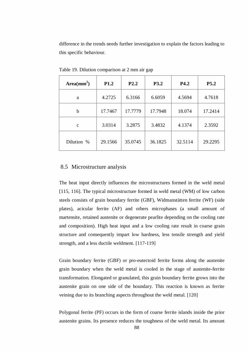
88
difference in the trends needs further investigation to explain the factors leading to
this specific behaviour.
Table 19. Dilution comparison at 2 mm air gap
Area(mm2) P1.2 P2.2 P3.2 P4.2 P5.2
a 4.2725 6.3166 6.6059 4.5694 4.7618
b 17.7467 17.7779 17.7948 18.074 17.2414
c 3.0314 3.2875 3.4832 4.1374 2.3592
Dilution % 29.1566 35.0745 36.1825 32.5114 29.2295
8.5 Microstructure analysis
The heat input directly influences the microstructures formed in the weld metal
[115, 116]. The typical microstructure formed in weld metal (WM) of low carbon
steels consists of grain boundary ferrite (GBF), Widmanstätten ferrite (WF) (side
plates), acicular ferrite (AF) and others microphases (a small amount of
martensite, retained austenite or degenerate pearlite depending on the cooling rate
and composition). High heat input and a low cooling rate result in coarse grain
structure and consequently impart low hardness, less tensile strength and yield
strength, and a less ductile weldment. [117-119]
Grain boundary ferrite (GBF) or pro-eutectoid ferrite forms along the austenite
grain boundary when the weld metal is cooled in the stage of austenite-ferrite
transformation. Elongated or granulated, this grain boundary ferrite grows into the
austenite grain on one side of the boundary. This reaction is known as ferrite
veining due to its branching aspects throughout the weld metal. [120]
Polygonal ferrite (PF) occurs in the form of coarse ferrite islands inside the prior
austenite grains. Its presence reduces the toughness of the weld metal. Its amount
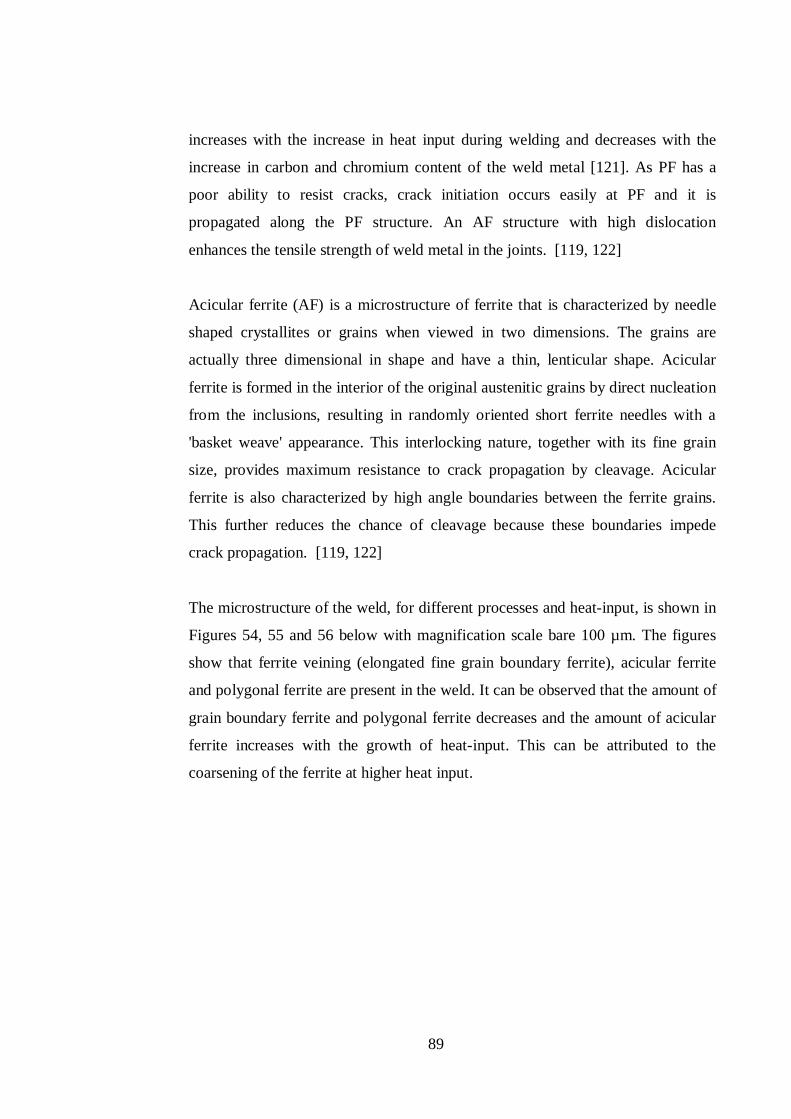
89
increases with the increase in heat input during welding and decreases with the
increase in carbon and chromium content of the weld metal [121]. As PF has a
poor ability to resist cracks, crack initiation occurs easily at PF and it is
propagated along the PF structure. An AF structure with high dislocation
enhances the tensile strength of weld metal in the joints. [119, 122]
Acicular ferrite (AF) is a microstructure of ferrite that is characterized by needle
shaped crystallites or grains when viewed in two dimensions. The grains are
actually three dimensional in shape and have a thin, lenticular shape. Acicular
ferrite is formed in the interior of the original austenitic grains by direct nucleation
from the inclusions, resulting in randomly oriented short ferrite needles with a
'basket weave' appearance. This interlocking nature, together with its fine grain
size, provides maximum resistance to crack propagation by cleavage. Acicular
ferrite is also characterized by high angle boundaries between the ferrite grains.
This further reduces the chance of cleavage because these boundaries impede
crack propagation. [119, 122]
The microstructure of the weld, for different processes and heat-input, is shown in
Figures 54, 55 and 56 below with magnification scale bare 100 µm. The figures
show that ferrite veining (elongated fine grain boundary ferrite), acicular ferrite
and polygonal ferrite are present in the weld. It can be observed that the amount of
grain boundary ferrite and polygonal ferrite decreases and the amount of acicular
ferrite increases with the growth of heat-input. This can be attributed to the
coarsening of the ferrite at higher heat input.
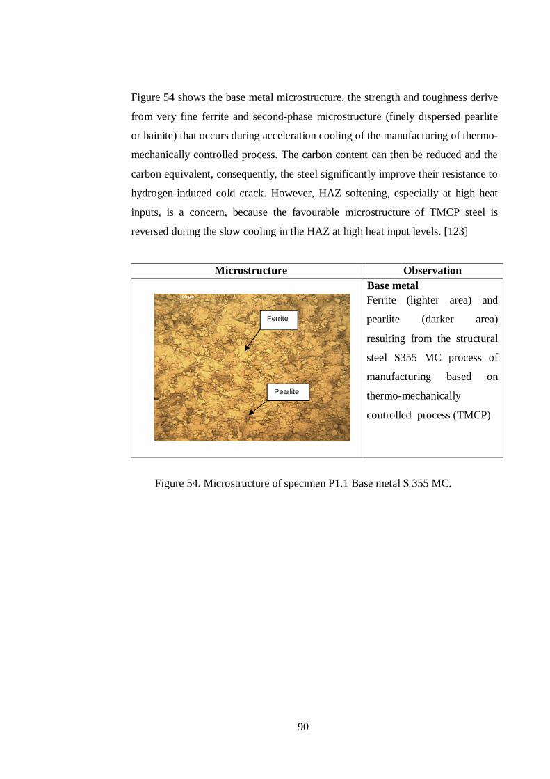
90
Figure 54 shows the base metal microstructure, the strength and toughness derive
from very fine ferrite and second-phase microstructure (finely dispersed pearlite
or bainite) that occurs during acceleration cooling of the manufacturing of thermo-
mechanically controlled process. The carbon content can then be reduced and the
carbon equivalent, consequently, the steel significantly improve their resistance to
hydrogen-induced cold crack. However, HAZ softening, especially at high heat
inputs, is a concern, because the favourable microstructure of TMCP steel is
reversed during the slow cooling in the HAZ at high heat input levels. [123]
Microstructure Observation
Base metal Ferrite (lighter area) and
pearlite (darker area)
resulting from the structural
steel S355 MC process of
manufacturing based on
thermo-mechanically
controlled process (TMCP)
Figure 54. Microstructure of specimen P1.1 Base metal S 355 MC.
Ferrite
Pearlite
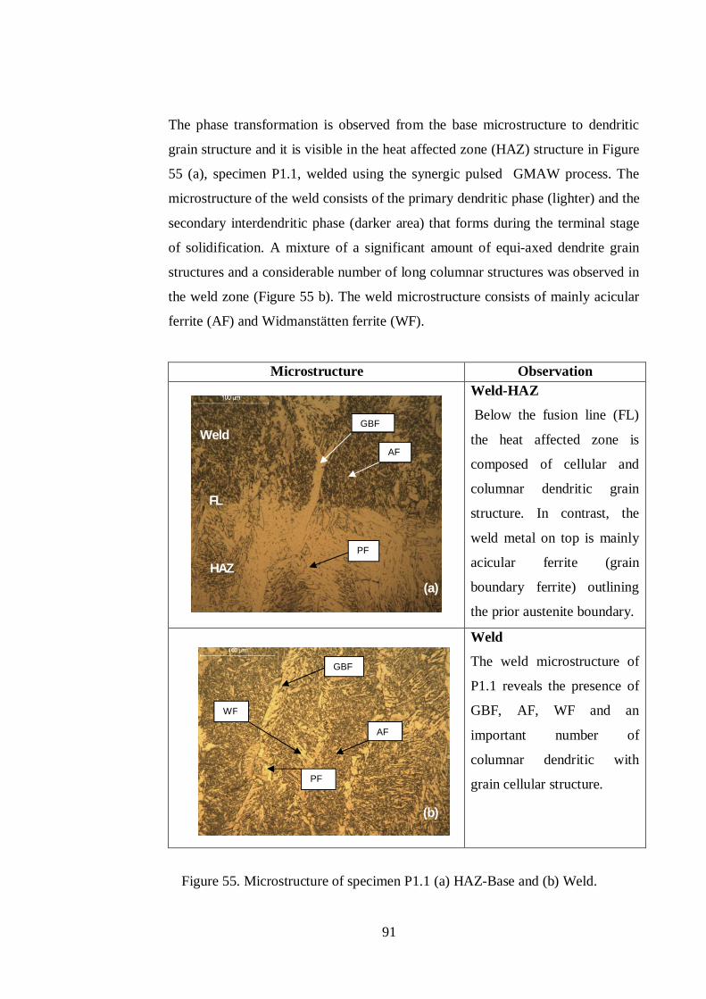
91
The phase transformation is observed from the base microstructure to dendritic
grain structure and it is visible in the heat affected zone (HAZ) structure in Figure
55 (a), specimen P1.1, welded using the synergic pulsed GMAW process. The
microstructure of the weld consists of the primary dendritic phase (lighter) and the
secondary interdendritic phase (darker area) that forms during the terminal stage
of solidification. A mixture of a significant amount of equi-axed dendrite grain
structures and a considerable number of long columnar structures was observed in
the weld zone (Figure 55 b). The weld microstructure consists of mainly acicular
ferrite (AF) and Widmanstätten ferrite (WF).
Microstructure Observation
Weld-HAZ
Below the fusion line (FL)
the heat affected zone is
composed of cellular and
columnar dendritic grain
structure. In contrast, the
weld metal on top is mainly
acicular ferrite (grain
boundary ferrite) outlining
the prior austenite boundary.
Weld
The weld microstructure of
P1.1 reveals the presence of
GBF, AF, WF and an
important number of
columnar dendritic with
grain cellular structure.
Figure 55. Microstructure of specimen P1.1 (a) HAZ-Base and (b) Weld.
HAZ
Weld
PF
AF
GBF
PF
AF
GBF
WF
(a)
(b)
FL
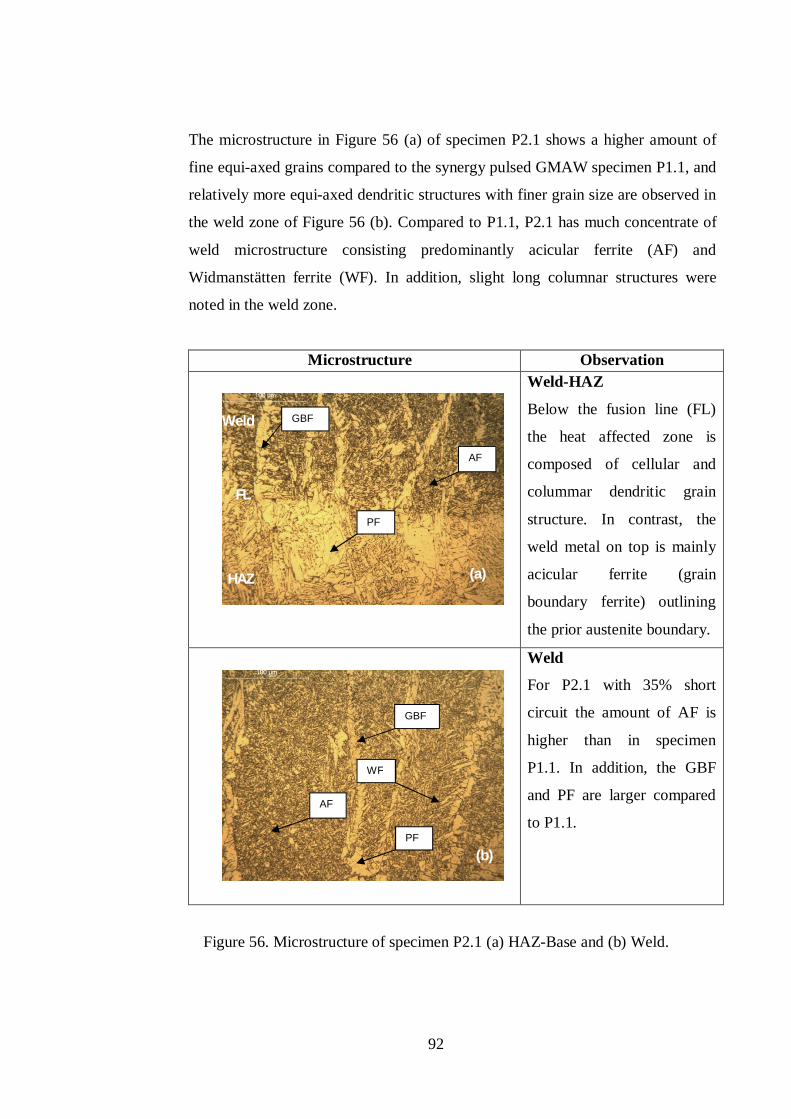
92
The microstructure in Figure 56 (a) of specimen P2.1 shows a higher amount of
fine equi-axed grains compared to the synergy pulsed GMAW specimen P1.1, and
relatively more equi-axed dendritic structures with finer grain size are observed in
the weld zone of Figure 56 (b). Compared to P1.1, P2.1 has much concentrate of
weld microstructure consisting predominantly acicular ferrite (AF) and
Widmanstätten ferrite (WF). In addition, slight long columnar structures were
noted in the weld zone.
Microstructure Observation
Weld-HAZ
Below the fusion line (FL)
the heat affected zone is
composed of cellular and
colummar dendritic grain
structure. In contrast, the
weld metal on top is mainly
acicular ferrite (grain
boundary ferrite) outlining
the prior austenite boundary.
Weld
For P2.1 with 35% short
circuit the amount of AF is
higher than in specimen
P1.1. In addition, the GBF
and PF are larger compared
to P1.1.
Figure 56. Microstructure of specimen P2.1 (a) HAZ-Base and (b) Weld.
HAZ
Weld
PF
AF
GBF
GBF
AF
PF
WF
(a)
(b)
FL
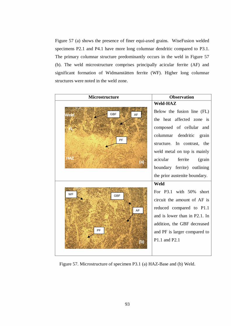
93
Figure 57 (a) shows the presence of finer equi-axed grains. WiseFusion welded
specimens P2.1 and P4.1 have more long columnar dendritic compared to P3.1.
The primary columnar structure predominantly occurs in the weld in Figure 57
(b). The weld microstructure comprises principally acicular ferrite (AF) and
significant formation of Widmanstätten ferrite (WF). Higher long columnar
structures were noted in the weld zone.
Microstructure Observation
Weld-HAZ
Below the fusion line (FL)
the heat affected zone is
composed of cellular and
colummar dendritic grain
structure. In contrast, the
weld metal on top is mainly
acicular ferrite (grain
boundary ferrite) outlining
the prior austenite boundary.
Weld
For P3.1 with 50% short
circuit the amount of AF is
reduced compared to P1.1
and is lower than in P2.1. In
addition, the GBF decreased
and PF is larger compared to
P1.1 and P2.1
Figure 57. Microstructure of specimen P3.1 (a) HAZ-Base and (b) Weld.
HAZ
Weld
PF
GBF AF
AF
GBF
PF
WF
(a)
(b)
FL
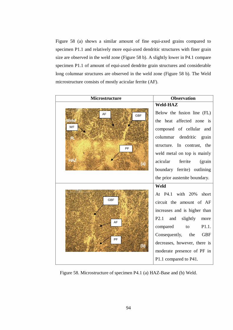
94
Figure 58 (a) shows a similar amount of fine equi-axed grains compared to
specimen P1.1 and relatively more equi-axed dendritic structures with finer grain
size are observed in the weld zone (Figure 58 b). A slightly lower in P4.1 compare
specimen P1.1 of amount of equi-axed dendrite grain structures and considerable
long columnar structures are observed in the weld zone (Figure 58 b). The Weld
microstructure consists of mostly acicular ferrite (AF).
Microstructure Observation
Weld-HAZ
Below the fusion line (FL)
the heat affected zone is
composed of cellular and
colummar dendritic grain
structure. In contrast, the
weld metal on top is mainly
acicular ferrite (grain
boundary ferrite) outlining
the prior austenite boundary.
Weld
At P4.1 with 20% short
circuit the amount of AF
increases and is higher than
P2.1 and slightly more
compared to P1.1.
Consequently, the GBF
decreases, however, there is
moderate presence of PF in
P1.1 compared to P41.
Figure 58. Microstructure of specimen P4.1 (a) HAZ-Base and (b) Weld.
HAZ
Weld
GBF
PF
AF
AF
PF
GBF
WF
(a)
(b)
FL
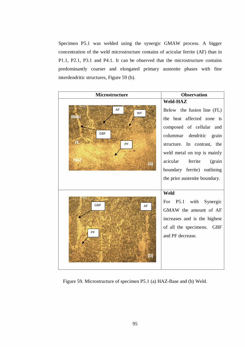
95
Specimen P5.1 was welded using the synergic GMAW process. A bigger
concentration of the weld microstructure contains of acicular ferrite (AF) than in
P1.1, P2.1, P3.1 and P4.1. It can be observed that the microstructure contains
predominantly coarser and elongated primary austenite phases with fine
interdendritic structures, Figure 59 (b).
Microstructure Observation
Weld-HAZ
Below the fusion line (FL)
the heat affected zone is
composed of cellular and
colummar dendritic grain
structure. In contrast, the
weld metal on top is mainly
acicular ferrite (grain
boundary ferrite) outlining
the prior austenite boundary.
Weld
For P5.1 with Synergic
GMAW the amount of AF
increases and is the highest
of all the specimens. GBF
and PF decrease.
Figure 59. Microstructure of specimen P5.1 (a) HAZ-Base and (b) Weld.
Weld
HAZ
AF
PF
GBF
PF
GBF
AF WF
(a)
(b)
FL
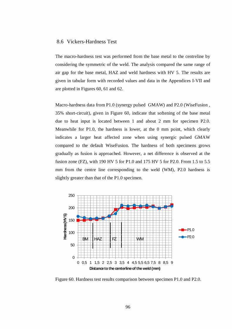
96
8.6 Vickers-Hardness Test
The macro-hardness test was performed from the base metal to the centreline by
considering the symmetric of the weld. The analysis compared the same range of
air gap for the base metal, HAZ and weld hardness with HV 5. The results are
given in tabular form with recorded values and data in the Appendices I-VII and
are plotted in Figures 60, 61 and 62.
Macro-hardness data from P1.0 (synergy pulsed GMAW) and P2.0 (WiseFusion ,
35% short-circuit), given in Figure 60, indicate that softening of the base metal
due to heat input is located between 1 and about 2 mm for specimen P2.0.
Meanwhile for P1.0, the hardness is lower, at the 0 mm point, which clearly
indicates a larger heat affected zone when using synergic pulsed GMAW
compared to the default WiseFusion. The hardness of both specimens grows
gradually as fusion is approached. However, a net difference is observed at the
fusion zone (FZ), with 190 HV 5 for P1.0 and 175 HV 5 for P2.0. From 1.5 to 5.5
mm from the centre line corresponding to the weld (WM), P2.0 hardness is
slightly greater than that of the P1.0 specimen.
Figure 60. Hardness test results comparison between specimen P1.0 and P2.0.
0
50
100
150
200
250
0 0,5 1 1,5 2 2,5 3 3,5 4 4,5 5,5 6,5 7,5 8 8,5 9
Hard
ness
(HV
5)
Distance to the centerline of the weld (mm)
P1.0
P2.0BM HAZ FZ WM
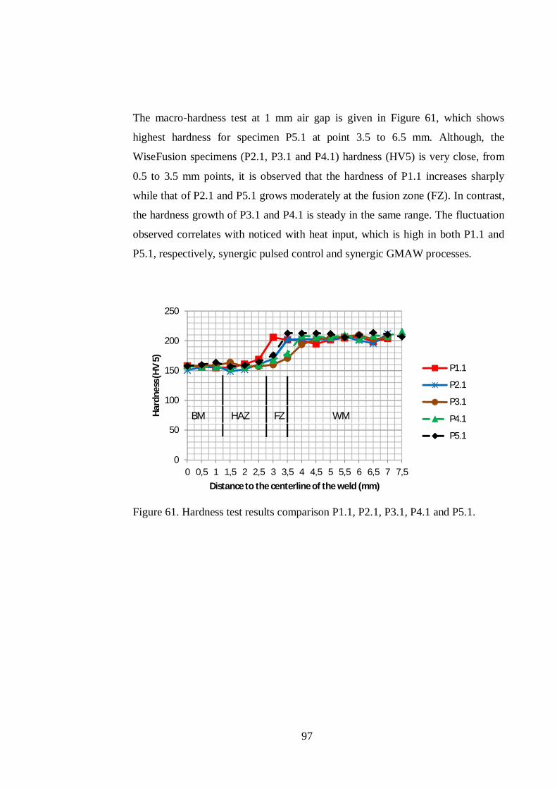
97
The macro-hardness test at 1 mm air gap is given in Figure 61, which shows
highest hardness for specimen P5.1 at point 3.5 to 6.5 mm. Although, the
WiseFusion specimens (P2.1, P3.1 and P4.1) hardness (HV5) is very close, from
0.5 to 3.5 mm points, it is observed that the hardness of P1.1 increases sharply
while that of P2.1 and P5.1 grows moderately at the fusion zone (FZ). In contrast,
the hardness growth of P3.1 and P4.1 is steady in the same range. The fluctuation
observed correlates with noticed with heat input, which is high in both P1.1 and
P5.1, respectively, synergic pulsed control and synergic GMAW processes.
Figure 61. Hardness test results comparison P1.1, P2.1, P3.1, P4.1 and P5.1.
0
50
100
150
200
250
0 0,5 1 1,5 2 2,5 3 3,5 4 4,5 5 5,5 6 6,5 7 7,5
Har
dnes
s (H
V 5)
Distance to the centerline of the weld (mm)
P1.1
P2.1
P3.1
P4.1
P5.1
BM HAZ FZ WM
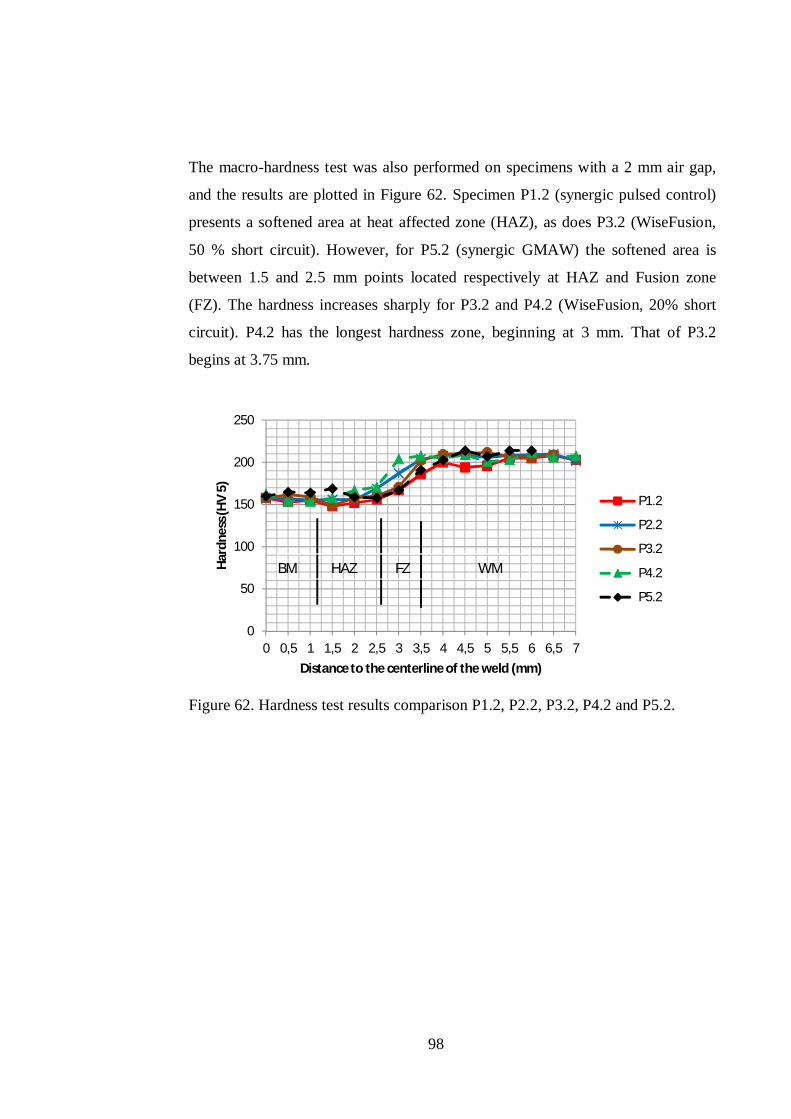
98
The macro-hardness test was also performed on specimens with a 2 mm air gap,
and the results are plotted in Figure 62. Specimen P1.2 (synergic pulsed control)
presents a softened area at heat affected zone (HAZ), as does P3.2 (WiseFusion,
50 % short circuit). However, for P5.2 (synergic GMAW) the softened area is
between 1.5 and 2.5 mm points located respectively at HAZ and Fusion zone
(FZ). The hardness increases sharply for P3.2 and P4.2 (WiseFusion, 20% short
circuit). P4.2 has the longest hardness zone, beginning at 3 mm. That of P3.2
begins at 3.75 mm.
Figure 62. Hardness test results comparison P1.2, P2.2, P3.2, P4.2 and P5.2.
0
50
100
150
200
250
0 0,5 1 1,5 2 2,5 3 3,5 4 4,5 5 5,5 6 6,5 7
Hard
ness
(HV
5)
Distance to the centerline of the weld (mm)
P1.2
P2.2
P3.2
P4.2
P5.2
BM HAZ FZ WM
99
9 CONCLUSIONS
During this study, whose objective was to evaluate the applications and benefits
of adaptive GMAW processes, three different processes; Synergic Pulsed
GMAW, WiseFusionTM and Synergic GMAW were used to weld a fillet weld (PB
position). It was decided to search for the best result and optimal conditions and
parameters. Based on visual, mechanical and chemical analysis, the following
conclusions can be drawn.
The high current density welding process is suitable for automation because it
requires high speed at its upper ranger to avoid humping. However, manual
applications can be performed at the lower speed range, due to the adaptive
control and stability of the arc. The low heat input compared to traditional
GMAW observed when using adaptive pulsed GMAW can be beneficial with a
structure subject to multiple welds, as it reduces significantly the total heat, and
thus limits distortion.
The thermal conductivity of the shielding gas affects the temperature of the arc
and the weld pool. Moreover, the electrical conductivity of the shielding gas
increases as the temperature increases. Therefore, shielding gas choice and
mixture influence the droplet transfer mode. Furthermore, the shielding gas
mixture also affects the weld penetration; for example, the PB weldment position
conducted with various portions of Argon and CO2 revealed higher penetration
with a maximum of 18% CO2.
The welding speed increases proportionally to the depth of penetration but it
decreases as the speed is increased beyond certain limits. This means that for any
welding condition, there is an optimum value of welding speed beyond which if
the speed is increased the depth of penetration drops. Based on the effect of
welding speed, arc current and welding voltage, higher welding bead penetration
is obtained with a larger electrode diameter and the gas flow rate has negligible
impact.
100
Conventional single wire heavy duty GMAW is based on wire extension, a high
current and relatively low voltage for high-energy short circuit processes and a
high voltage for high-energy spray processes. The productivity achieved with
high-energy short circuiting arc processes varies between 8-18 kg/h, and that of
high-energy spray arcs is 20 kg/h. The drawbacks of conventional high energy
processes are the instability of the arc, humping and excessive heat. These
problems can be successfully solved by utilization of a digitally controlled power
source machine.
Compared to synergic pulsed GMAW, the profile of the weld generated with
WiseFusion is bigger, with deeper side wall and a shorter root penetration. This
reduces the risk of burn-through when welding plate of thin sections smaller or
equal to 5 mm by increasing the welding speed and energy input.
Weld design with difficult access, such as narrow angles, has been challenging for
weld torch orientation and has resulted in arc stability problems and poor weld
quality. Adaptive pulsed GMAW provides an alternative to electrode extension
and better control of the arc. A concrete example is the ForceArc process.
Adaptive pulsed GMAW processes are based on complex waveform current and
voltage. It is difficult to evaluate the mean current and voltage, which can result in
error when estimating the heat input. A new approach has been suggested by
ASME section IX which gives more accurate results, although the power source
must be able to display the total energy after welding.
Increase in the welding current in the synergic pulsed GMAW process reduces the
columnar growth of dendrites in the matrix. The morphology of the bainite was
found to change with variation in welding parameters. The pulse current resulted
in a coarse microstructure with respect to the growth of dendrites, especially at
higher pulse frequency and pulse duration, due to reduced cooling rates. However,
pulse current welding carried out at higher arc voltage was found to be beneficial
for the production of a finer weld microstructure. Compared to synergic pulsed
GMAW, the weld zone in short circuit GMAW contained a more dendritic
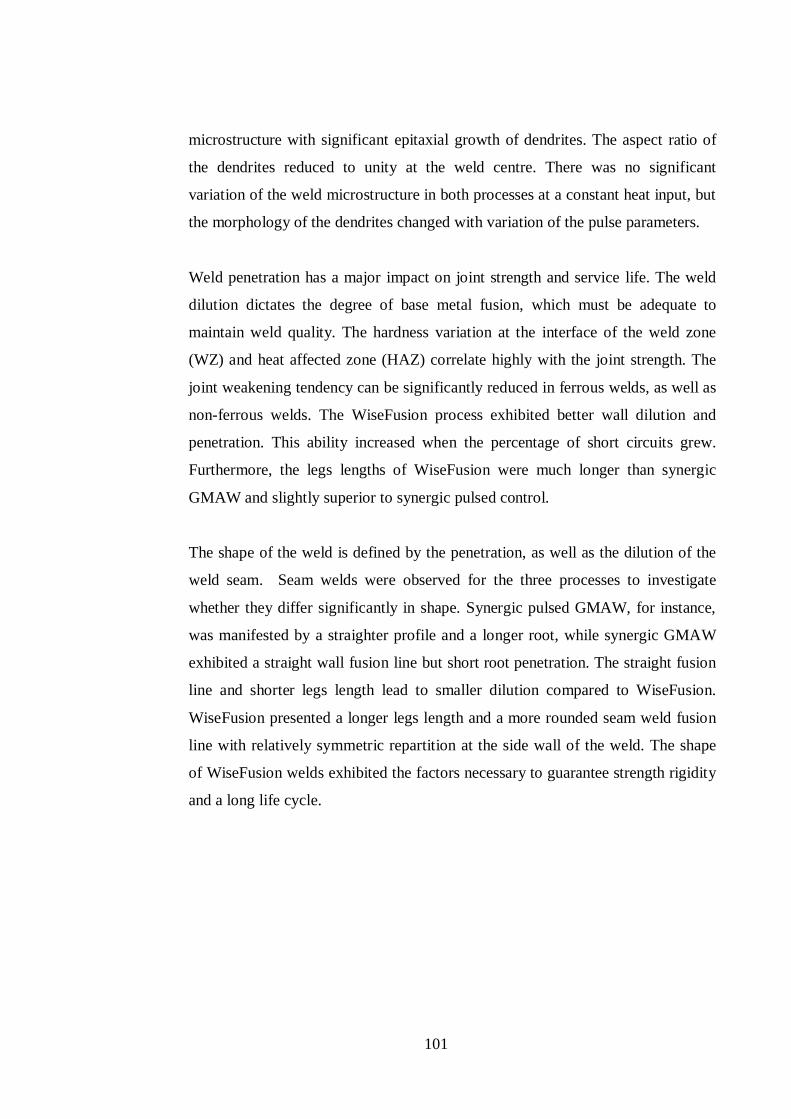
101
microstructure with significant epitaxial growth of dendrites. The aspect ratio of
the dendrites reduced to unity at the weld centre. There was no significant
variation of the weld microstructure in both processes at a constant heat input, but
the morphology of the dendrites changed with variation of the pulse parameters.
Weld penetration has a major impact on joint strength and service life. The weld
dilution dictates the degree of base metal fusion, which must be adequate to
maintain weld quality. The hardness variation at the interface of the weld zone
(WZ) and heat affected zone (HAZ) correlate highly with the joint strength. The
joint weakening tendency can be significantly reduced in ferrous welds, as well as
non-ferrous welds. The WiseFusion process exhibited better wall dilution and
penetration. This ability increased when the percentage of short circuits grew.
Furthermore, the legs lengths of WiseFusion were much longer than synergic
GMAW and slightly superior to synergic pulsed control.
The shape of the weld is defined by the penetration, as well as the dilution of the
weld seam. Seam welds were observed for the three processes to investigate
whether they differ significantly in shape. Synergic pulsed GMAW, for instance,
was manifested by a straighter profile and a longer root, while synergic GMAW
exhibited a straight wall fusion line but short root penetration. The straight fusion
line and shorter legs length lead to smaller dilution compared to WiseFusion.
WiseFusion presented a longer legs length and a more rounded seam weld fusion
line with relatively symmetric repartition at the side wall of the weld. The shape
of WiseFusion welds exhibited the factors necessary to guarantee strength rigidity
and a long life cycle.
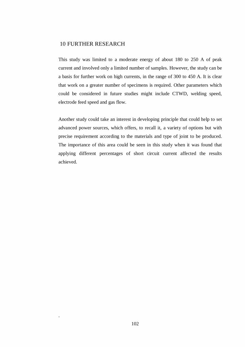
102
10 FURTHER RESEARCH
This study was limited to a moderate energy of about 180 to 250 A of peak
current and involved only a limited number of samples. However, the study can be
a basis for further work on high currents, in the range of 300 to 450 A. It is clear
that work on a greater number of specimens is required. Other parameters which
could be considered in future studies might include CTWD, welding speed,
electrode feed speed and gas flow.
Another study could take an interest in developing principle that could help to set
advanced power sources, which offers, to recall it, a variety of options but with
precise requirement according to the materials and type of joint to be produced.
The importance of this area could be seen in this study when it was found that
applying different percentages of short circuit current affected the results
achieved.
.
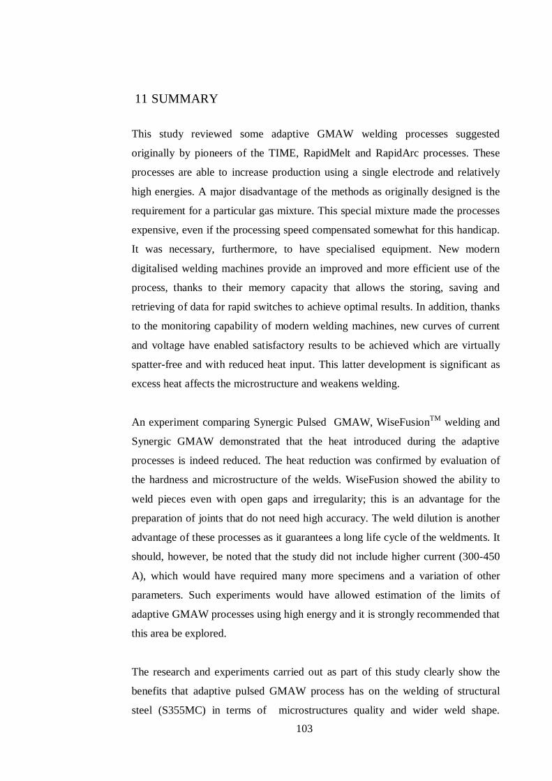
103
11 SUMMARY
This study reviewed some adaptive GMAW welding processes suggested
originally by pioneers of the TIME, RapidMelt and RapidArc processes. These
processes are able to increase production using a single electrode and relatively
high energies. A major disadvantage of the methods as originally designed is the
requirement for a particular gas mixture. This special mixture made the processes
expensive, even if the processing speed compensated somewhat for this handicap.
It was necessary, furthermore, to have specialised equipment. New modern
digitalised welding machines provide an improved and more efficient use of the
process, thanks to their memory capacity that allows the storing, saving and
retrieving of data for rapid switches to achieve optimal results. In addition, thanks
to the monitoring capability of modern welding machines, new curves of current
and voltage have enabled satisfactory results to be achieved which are virtually
spatter-free and with reduced heat input. This latter development is significant as
excess heat affects the microstructure and weakens welding.
An experiment comparing Synergic Pulsed GMAW, WiseFusionTM welding and
Synergic GMAW demonstrated that the heat introduced during the adaptive
processes is indeed reduced. The heat reduction was confirmed by evaluation of
the hardness and microstructure of the welds. WiseFusion showed the ability to
weld pieces even with open gaps and irregularity; this is an advantage for the
preparation of joints that do not need high accuracy. The weld dilution is another
advantage of these processes as it guarantees a long life cycle of the weldments. It
should, however, be noted that the study did not include higher current (300-450
A), which would have required many more specimens and a variation of other
parameters. Such experiments would have allowed estimation of the limits of
adaptive GMAW processes using high energy and it is strongly recommended that
this area be explored.
The research and experiments carried out as part of this study clearly show the
benefits that adaptive pulsed GMAW process has on the welding of structural
steel (S355MC) in terms of microstructures quality and wider weld shape.
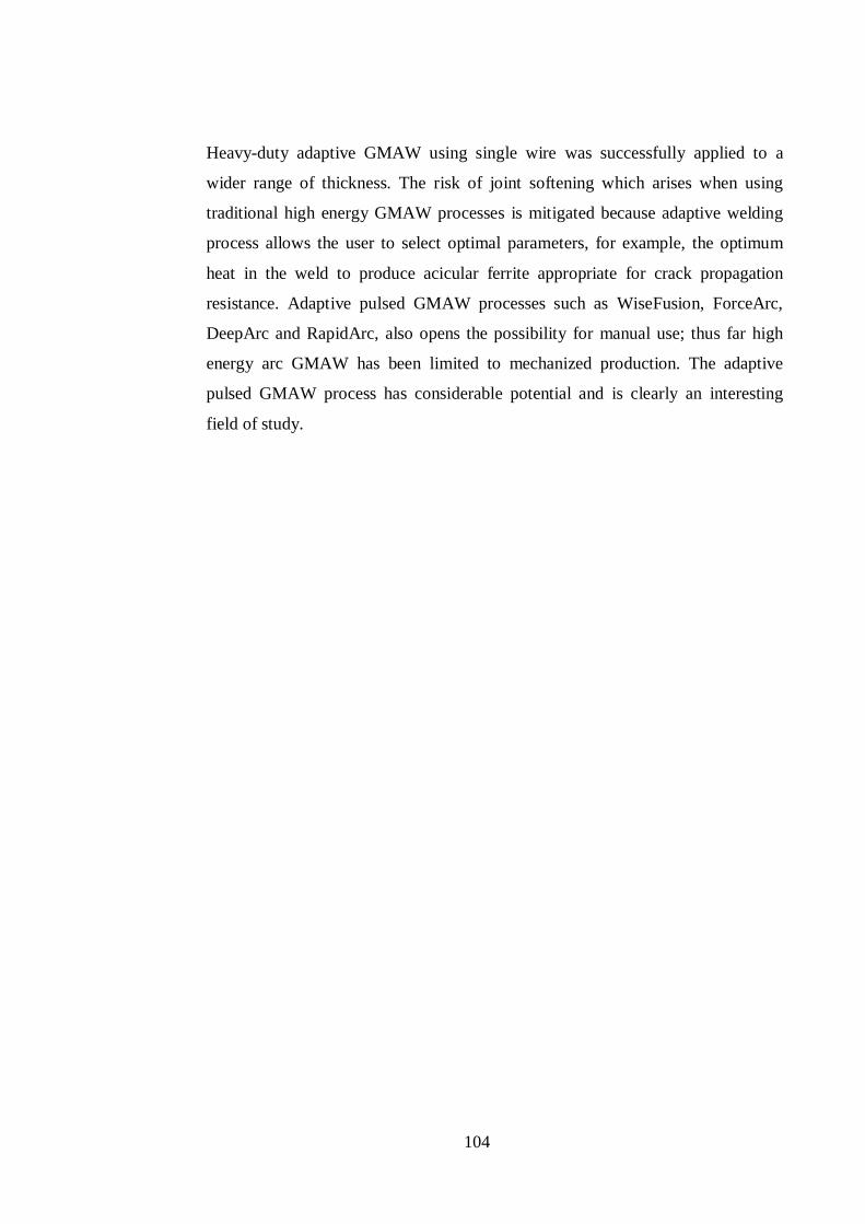
104
Heavy-duty adaptive GMAW using single wire was successfully applied to a
wider range of thickness. The risk of joint softening which arises when using
traditional high energy GMAW processes is mitigated because adaptive welding
process allows the user to select optimal parameters, for example, the optimum
heat in the weld to produce acicular ferrite appropriate for crack propagation
resistance. Adaptive pulsed GMAW processes such as WiseFusion, ForceArc,
DeepArc and RapidArc, also opens the possibility for manual use; thus far high
energy arc GMAW has been limited to mechanized production. The adaptive
pulsed GMAW process has considerable potential and is clearly an interesting
field of study.
105
REFERENCES
[1] K. Ferjutz and J. R. Devis, ASM Handbook,Volume 6, Welding Brazing
and Soldering, Metals Park, Ohio: ASM International, 1993.
[2] K. Weman and L. Gunnar, MIG Welding Guide, Cambridge: Woodhead
Publishing and Maney Publishing, 2006.
[3] J. Norrish, “Arc welding power sources – design evolution and welding
characteristics,” IIW Doc, XII-1215-91, 1991.
[4] S. Adolfsson, P. Bahrami et al, “On line quality monitoring in short circuit
GMA welding,” Welding Journal, Research Supplement, pp. 59s–73s, Feb
1999.
[5] K. Himmelbauer, “Digital Welding,” Fronius International, Property
reports and presentations, 2003.
[6] K. Weman, Welding Process Handbook, Cambridge, England: Woodhead
Publishing Limited, 2003.
[7] J. F. Lancaster, The Physics of Welding, Oxford: Pergamon Press, 1984.
[8] J. Norrish, “A review of metal transfer classification in arc,” in IIW Doc,
Bucharest, 2003.
[9] J. Nadzam, “Gas metal arc welding: process overview,” Lincoln Electric
Company, Technology Center, Internal report, 2003.
[10] C. Howard B, Modern Welding Technology, 3 rd ed., New Jersey:
Regents/Prentice Hall, Englewood Cliffs , 1994.
[11] Robert W. Messler Jr., Principles of Welding, Processes, Physics,
Chemistry, and Metallurgy, Singapore: WILEY-VCH Verlag GmbH &
Co. KGaA, Weinheim, 2004.
106
[12] J. Taylor, An Engineer's Guide to Fabrication Steel Structures; Fabrication
Methods, Sydney: Australian Institute of Steel Construction, 2001.
[13] R. Killing, H. Sönnichsen and G. Glowicki, “Beitrag zur Klassifizierung
des Werkstoffüberganges beim Metallschutzgasscheißen,” Schweissen und
Schneiden, vol. 36, no. 12, pp. 575-578, 1984.
[14] E. Smårs and K. Acinger, “Material transport and temperature distribution
in arc melting,” IIW-Document 212-168-68, International Institut of
Welding Study Group SG212, Physics of Welding, 1968.
[15] C. L. Jenney and A. O'Brien, Welding Handbook, 9th Edition, Volume 1,
Welding Science and Technology, 9th; vol. 1 ed., C. L. Jenney and A.
O'Brien, Eds., Miami, FL 33126, USA: (AWS) Amercan Welding
Society, 2001.
[16] H. Granjon, Fundamentals of Welding Metallurgy, Cambridge: Woodhead
Publishing, 1991.
[17] D. G. Deyev and G. F. Deyev, “Surface Phenomena in Fusion Welding
Processes,” London, CRC Press Taylor & Francis Group, 2006, pp. 135-
139.
[18] S. I. Pinchuk, V. F. Postaushkin and G. D. Kulikov, “Nature of action of
surface,” Avtom. Svarka, pp. 11, 24, 1974.
[19] M. Beckert et al, “Neues in der schweisstechnik 1985.
werkstoffgrundlagen und,” Schweisstechnik (DDR), vol. 36, no. 5, p. 214,
1985.
[20] R. Killing, “Angewandte Scheweißmetallugie-Anleitum für die Praxis,
Fachbuchreihe Schweißtechnik Band 113,” Düsseldorf, Deutscher verlag
für schweißtechnik DVS-verlag GmbH, 1996, pp. 74-77.
[21] Y. S. Kim and T. W. Eagar, “Analysis of metal transfer in Gas Metal Arc
107
Welding,” Welding Journal, pp. 269-278, June 1993.
[22] R. Killing, “Schutzgase zum Lichtbogenschweißen -,” Der Praktiker, vol.
45, no. 8, pp. 451-454, 1993.
[23] H. Matzner, “Qualitätssteigerung beim spritzeram en MAGM-
impulslichtbogenschweißen durch Regelung der Prozeßgrößen,
Schweißtechnische Forschungsberichte, Band 40,” Düsseldorf, Deutsher
Verlag für Schweißtechnik (DVS) GmbH, 1991, pp. 9, 13.
[24] D. Dzelnitzki, “Increasing the deposition volume or the welding speed?-
Advantages of heavy-duty MAG welding,” Welding and Cutting, no. 9,
pp. E197-E204, 1999.
[25] ISF, “5-Gas-sheilding metal arc welding,” The Welding and Joining
Institute (ISF) of RWTH, Aachen University in Germany, 2002.
[26] F. Jeffus Larry, “Welding: Principles and Applications,” Clifton Park,
New York, Delmar Cengage Learning, ISBN 1401810462, 2002, p. 218 –
225.
[27] L. Baum and V. Fichter, “Der schutzgasschweisser, teil 2, MIG/ MAG
schweissen,” Die schweißtechnische Praxis, DVS- Verlag, no. 12, 1999.
[28] Anon, “Classification of metal transfer,” in IIW Doc. XII-636-76, 1976.
[29] J. Ma, “Metal Transfer in MIG Welding,” Crandfield Institute of
Technology, Bedfordshire, U.K., PhD Thesis, 1982.
[30] W. Lucas, D. Iordachescu and V. Ponomarev, “Classification of metal
transfer modes in GMAW,” in IIW Doc. No XII-1859-05, Prague, 2005.
[31] D. Iordachescu and L. Quintino, “Steps toward a new classification of
metal transfer in gas metal arc welding,” Journal of Materials Processing
Technology, vol. 202, pp. 391-397, 2008.
108
[32] E. Karadeniz, U. Ozsarac and C. Yildiz, “the effect of process parameters
on penetration in gas metal arc welding processes,” Journal of Materials
and Design, vol. 28, pp. 649-656, 2007.
[33] S. Liu and T. A. Siewert, “Metal transfer in gas metal arc welding: droplet
rate,” Welding Journal, vol. 68, no. 2, pp. 52-58, 1989.
[34] W. J. So, M. J. Kang and D. C. Kim, “Weldability of pulse GMAW joints
of 780 MPa dual-phase steel,” International Scientific Journal, vol. 41,
no. 1, pp. 53-60, January 2010.
[35] H. Wolters and P. Åberg, “QSetTM - a breakthrough in welding
technology!,” The ESAB Welding and Cutting Journal, vol. 61, no. 1, pp.
36-37, 2006.
[36] M. Suban and J. Tusek, “Dependence of melting rate in MIG/MAG
welding on the type of shielding gas used,” J. Mater. Process. Technol.,
vol. 119, pp. 185–192, 2001.
[37] J. N. Pires, A. Loureiro and G. Bölmsjo, Welding Robots Technology,
System Issues and Application, London: Springer/978-1-85233-953-1,
2006.
[38] V. Stenke, Besonderheiten und Eigenschaften von Mehrkomponentengas
in der Schweißtechnik, Düsseldorf: DVS-Berichte 155, DVS-verlag, 1993.
[39] V. Stenke, “Schutzgasauswahl - vom CO2 zum T.I.M.E. Gas.,” in Dodatni
i pomo ni materijali za zavariva ke i srodne postupke, Pore , 1996.
[40] K. A. Lyttle, “Shielding gases, Welding, Brazing and Soldering,” in ASM
Handbook, Vol 6, Metals Park, Ohio, ASM International, 1993, pp. 64-69.
[41] I. Pires, T. Rosado, A. Costa and L. Quintino, “Influence of GMAW
shielding gas in productivity and gaseous emissions,” in 10th
International Aachen Welding Conference,, Aachen, Germany, October
109
2007..
[42] I. S. Kim, A. Basu and E. Siores, “Mathematical models for control of
weld bead penetration in the GMAW process,” Int. J. Adv. Manuf.
Technol., vol. 12, pp. 393-401, 1996.
[43] J. S. Allen and D. Wildgery, “Cored Wire developments and objectives of
BS 7084,” Weld. Met. Fabr, vol. 6, pp. 274-282, 1990.
[44] H. Imaizumi and J. Church, “Welding characteristics of a new welding
process, T.I.M.E process,” in IIW Doc No. XII-1199-90, 1990.
[45] Publ AGA Co, Facts About: Rapid Arc, Rapid Melt-High Productivity
MIG/MAG, 1993.
[46] S. Trube, “High performance MAG welding with the Linfast,” in IIW Doc
No. XII-1499-97, 1997.
[47] B. Czwornog, “High energy MAG welding - arc shielding gases,” Biul
Inst Spawalnictwa, vol. 1, pp. 30-34, 1997.
[48] B. Czwornog, “Properties of weld and joints MAG-weld using high arc
energy levels,” Welding Journal, vol. 15, no. 6, pp. 425-430, 2001.
[49] M. Schellhase, “Der Schweißlichtbogen-ein technologisches Werzeug,
Fachbuchreihe Schweißtechnik, Band 84,,” Düsseldorf, Deutscher Verlag
für Schweißtechnik (DVS) GmbH, 1985, pp. 60, 68-70, 144.
[50] S. Trube, “MAG-Hochleistungsschweißen mit dem LINFAST®-
Konzept,” Linde AG, Hoellriegelskreuth, 1997.
[51] N. V. Pepe, “Advances in GMAW and application to corrosion resistant
alloy pipes,” Cranfield University, UK, PhD Thesis, 2010.
[52] D. S. West, J. Neuberger, R. Lahnsteiner and A. Overton, “Revolutionary
improvements in automated robot welding,” in TWI Conf. Automated
110
welding systemsin manufacturing, 17-19 November 1991. TWI paper 35,
Gateshead, North East UK, 1991.
[53] E. Halmoy et al, “The T.I.M.E. welding method compared with GMAW,”
Doc. XII-1248-91, IIW 1991., 1991.
[54] P. F. Mendez and T. W. Eagar, “Penetration and defect formation in high-
current arc welding,” Welding Journal, pp. 296s-306s, Otober 2003.
[55] S. Adolfsson, P. Bahrami et al, “On line quality monotoring in short
circuit GMA welding,” Welding Journal, Research Supplement, pp. 59s-
73s, Feb 1999.
[56] N. Ahmed, New Development in Advanced Welding, Cambridge:
Woodhead Publishing Limited, 2005.
[57] Hamamoto et al, “Development of Digitally-Controlled Welding
Machines,” in Welding Process Guide Book Vol.5 ‘Improvement of
efficiency in welding processes’, W. P. S. C. I. Welding Society, Ed.,
Welding Society, Welding Process Study Committee II-99., 2004.
[58] Furukawa, “Inert gas arc welding machine in Europ,” Light Metal
Welding, vol. 43, no. 4, 2005.
[59] Mita, “Present state of our company's iner gas arc welding machine and its
prospect,” Light Metal Welding, vol. 53, no. 8, 2005.
[60] T. Ogasawara, T. Maruyama, T. Saito, M. Sato and Y. Hida, “A power
source of gas shielded arc welding with new current waveforms,” Welding
Journal, vol. 66, no. 3, pp. 57–63, 1987.
[61] E. K. Stava, “A new, low spatter,” Welding Journal, vol. 72, no. 1, pp. 25–
29, 1993.
[62] S. F. Goecke, “Energiereduziertes Lichtbogen-Fügeverfahren für
Wärmeempfindliche Werkstoffe (Reduced Energy Laser Process for Heat
111
Sensitive Materials),” DVS-Berichte, vol. 237, pp. 44–48, 2005.
[63] J. Cuhel, “Modified short circuit and pulsed gas metal arc welding
technologies increase pipe welding productivity, improve quality, and ease
training,” welding Journal, pp. 66-68, June 2008.
[64] J. C. Needham and A. W. Carter, “Material transfer characteristics with
pulsed current,” Br. Welding J., vol. 12, no. 5, pp. 229-41, 1965.
[65] J. C. Needhan, “Control of transfer in aluminium consumable electrode
welding,” Physics of Welding Arc, The Institute of Welding, London, pp.
114-124, 1962.
[66] W. Shimada and Ukai, “Effects of pulsed current control on welding
quality improvement,” IIW Document XII-B-81, 1981.
[67] P. K. Ghosh and B. K. Rai, “Characteristics of pulsed current bead on
plate deposite in flux cored GMAW process,” ISIJ Int, vol. 36, no. 8, pp.
1036-1045, 1996.
[68] P. K. Ghosh, S. R. Gupta and H. S. Randhawa, “Characteristics of a
pulsed-current, vertical-up gas metal arc weld in steel,” Metall. Mater.
Trans. A, vol. 31A, pp. 2247-2259, 2000.
[69] S. Elliott, Met. Construction, pp. 148–151, 1985.
[70] M. Amin and P. V. C. Watkins, “Synergic pulse MIG welding,” Weld.
Inst. Res. Rep., p. 46, 1977.
[71] J. Norrish, Advanced Welding Process; Technologies and Process Control,
Cambridge: Woodhead Publishing Limited, 2006.
[72] C. J. Allum, “MIG welding —time for a reassessment,” Met.
Construction, vol. 15, no. 6, pp. 347–353, 1983.
[73] C. L. Mendes da Silva and A. Scotti, “Performance assesment of the
112
(Trans) Varestraint test for determing solidification cracking suceptibility
when using welding processes with filler metal,” Meas Sci Technology,
vol. 15, pp. 2215–2223, 2004.
[74] C. L. Mendes da Silva and A. Scotti, “The influence of double pulse on
porosity formation in aluminum GMAW,” J Mater Process Technol, vol.
171, pp. 366–372, 2006.
[75] Mita, “IT processing for welding power,” J Jpn Wels Soc, vol. 1, 1997.
[76] M. R. Bosworth and R. T. Deam, “Influence of GMAW droplet size on
fume formation rate,” J Phys D: Appl Phys, vol. 33, pp. 2605–2610, 2000.
[77] Matsui, “Study for improvement of weld quality in thin sheet welding
execution,” in Proc Conf 10th Seminar, Welding and joining Engineering
Bureau.
[78] A. R. Doodman Tipi, “The study on the drop detachment for automatic
pipeline GMAW system: free flight mode.,” Int J Adv Manu Tech, vol. 50,
pp. 137–14715, 2010.
[79] M. F. Iwami, “Development of a large-current AC-MIG welding method,”
J Jpn Weld Soc, vol. 10, no. 5, pp. 83-88, 1992.
[80] J. Tanimoto, M. Minooka and Y. Nishida, “Development of the AC pulse
MIG welding process,” in Proceedings of the IIW Asian Pacific Regional
Welding Congress, 36th Annual AWI Conference., 1988.
[81] H. Harada et al, “The state-of-the-art of AC GMAW process in Japan,”
IIW Doc XII-1589-99, 1999.
[82] H. Tong et al, “Quality and productivity improvement in aluminium ally
thin sheet welding using alternating current pulsed metal inert gas welding
system,” Science and Technology of Welding and joining, vol. 6, no. 4, pp.
203-208, 2001.
113
[83] G. Huismann, “Introduction of new MIG process-advantage and
possiblity,” in IIW, 1999.
[84] D. Cuiuri, J. Norrish, G. Dean, P. Di Pietro and C. David Cook, “Control
method and system for metal arc welding”. Patent WO/2003/101658,
2003, 2003.
[85] Y. Wu and R. Kovacevic, “Mechanically assisted droplet transfer process
in gas metal arc welding,” J Engineering Manufacture, vol. Proc Instn
Mech Engrs Vol 216, no. Part B, pp. 555-564, 2002.
[86] S. Y. Yang, “Projected droplet transfer control with additional mechanical
forces (AMF) in MIG/MAG welding process,” Harbin Institute of
Technology, PhD dissertation, 1998.
[87] Fronius, “CMT Advanced-New development,” Schweissen & Schneiden,
pp. 8-10, 2009.
[88] Gerd Trommer Gernsheim, “‘Fronius: Technologie – und
Anwendungsinnovationen mit dem, CMT Advanced, - Prozess,” Welding
and Cutting Today, no. 2, p. 12, 15.9 2009.
[89] Maritime-executive, “Reaching the limit of arc welding,” 24 September
2009,http://www.maritime-executive.com/pressrelease/latest-news-
fronius-international-gmbh/.- [Accessed 15 March 2012].
[90] R. Fokens, “Cold Metal Transfer - CMT - A revolution in mechanized root
pass pipeline welding,” in 4th Pipeline Technology Conference, Hannover
Messe, Hannover, Germany, 2009.
[91] V. Ponomarev, A. Scotti, A. Silvinskiy and O. Al-Erhayem, “Atlas of
MIG/MAG welding metal transfer modes,” in Proc conf IIW, Doc.XII-
1771 to 1775-03, Bucharest, 2003.
[92] T. Anderson, “Aluminium Q&A,” Welding Journal, pp. 20-23, 8 2009.
114
[93] A. P. Joseph, “Assessing the effect of GMAW-Pulse parameters on arc
power and welding heat input,” Master's Thesis, Ohio state university,
2001.
[94] M. R. Bosworth, “Effective Heat input in pulsed current gas metal arc
welding with solid wire electrods,” Welding Journal, vol. 70, no. 5, pp.
111s-117s, May 1991.
[95] J. C. Needham, “What do you mean by current?,” Welding Institute
Research Bulletin, vol. 26, no. 8, pp. 273-277, August 1985.
[96] J. C. Needham, “What do you mean by voltage?,” Welding Institute
Research Bulletin, vol. 26, no. 9, pp. 331-316, September 1985.
[97] G. B. Melton, “Measurement of the arc welding parameters and validation
of equipment,” in Eurojoin 2, Florence, 1994.
[98] U. Dilthey and R. Killing, “Heat input for pulse GMAW,” Welding Design
Fabrication, vol. 63, no. 9, pp. 51-53, Septembre 1990.
[99] A. I. Sergeev, A. V. Mitulinskaya and K. L. Serpilin, “Selection methods
of measuring the energy parameters of welding with control of active
power,” Paton Welding Journal, vol. 2, no. 9, pp. 650-653, 1990.
[100] A. Joseph, D. D. Harwig, D. F. Farson and R. Richardson, “Assessing the
effects of GMAW-P parameters on arc power and weld heat input,” in
84th AWS Annual Conference, Detroit, MI, USA, 2003.
[101] T. Melfi, “New code requirements for calculating heat input,” welding
Journal, pp. 61-63, June 2010.
[102] J. Norrish, “Process modification in Gas Metal Arc Welding for enhanced
performance,” in WTIA/IIW Congress , Cairns, Queensland, Australia, 25-
28 September 2011, 2011.
115
[103] J. Uusitalo, “FastMigTM synergic and pipe welding,” Kemppi Pro News,
p. 8, 3 2005.
[104] P. Kah, “Welding of sheet metal using modified short arc,” Lappeenranta
University of Technology, Master's Thesis, 2007.
[105] J. Uusitalo, “Modified short arc process-new way of welding root passes.’
Economic and Ecological Aspects,” in Proceeding of the IIW
International Conference: Welding & Materials-Technica, Croatia:
Dubrovnik & Cavtat, 2007.
[106] T. Peltola, J. Kumpulainen and M. Veikkolainen, “Novel tailored welding
arcs help welders meet quality and productivity demands,” Innovation and
Business Development at Kemppi Oy, Finland, pp. 15-18.
[107] Kemppi Oy, “files/Kemppi Wise,Match Software Manual,”
http://www.rapidwelding.com/files/Kemppi%20Wise,Match%20Software
%20Manual.pdf. [Accessed 20 March 2012].
[108] A. M. Torbati, R. M. Miranda, L. Quintino, S. Williams and D. Yapp,
“Optimization procedures for GMAW of bimetal pipes,” Journal of
Materials Processing Technology, vol. 211, no. 6, p. 1112–1116, 2011.
[109] SFS Suomen Standardisoimisliitto “SFS-EN 10149-2:1996.(EN 10149-
2:1995), Kuumavalssatut lujat kylmämuovattavat teräslevytuotteet,” Osa
2: Termomekaanisesti valssattujen terästen toimitusehdot., Suomen
Standardisoimisliitto SFS ry. 14 s., 1995.
[110] R. Stout, “Weldability of steels,” Welding Research Council, pp. 3–4, 263,
1987.
[111] SFS Suomen Standardisoimisliitto, “SFS-EN 440, Hitsausaineet.
Hitsauslangat ja hitsiaineet seostamattomien terästen ja hienoraeterästen
metallikaasukaarihitsaukseen. Luokittelu,” Suomen Standardisoimisliitto
SFS, 1995.
116
[112] SFS Suomen standardisoimisliitto, Hitsien tarkastus. Osa 1. Rikkomaton
aineenkoetus, Syyskuu 2001.
[113] SFS Suomen standardisoimisliitto, Hitsien tarkastus. Osa 2. Rikkova
aineenkoetus, Huhtikuu 1999.
[114] C. L. Estes and P. W. Turner, “Filler metal dilution annd compsition in
dissimillar-metal welding,” Welding Journal, vol. 43, p. 541s, 1964.
[115] L. E. Svensson, Control of Microstructures and Properties in Steel Arc
Welds, London: CRC Press, 1994.
[116] K. Easterling, Introduction to the Physical Metallurgy of Welding, 2nd ed.,
Oxford: Butterworth-Heinemann, 1992.
[117] M. Aksoy, M. Ero and N. Orhan, “Effect of coarse initial grain size on
microstructure and mechanical properties of weld metal and HAZ of a low
carbon steel,” Material Science and Engineering, vol. 1, no. 269, pp. 1-9,
1999.
[118] S. S. Babu, “Current opinion in solid state and materials science,” Curr.
Opin. Solid State Mater. Sci., vol. 8, p. 267, 2004.
[119] S. S. Babu, “The mechanism of acicular ferrite in weld deposits,” Curr
Opin Solid State Mater Sci, vol. 8, no. 3–4, pp. 267–278, 2004.
[120] R. E. Dolby, “Advances in welding metallurgy of steel,” Metals
Technology, no. 10, pp. 349 – 362, 1983.
[121] D. J. Abson, A. Duncan and R. J. Pargeter, “Guide to the light microscope
examination of ferritic steel weld metals,” IIW DOC. IX-1533-88, IXJ-
123-87, revision 2, June 1988.
[122] M. Q. Johnson, G. M. Evans and G. R. Edwards, “The effect of thermal
cycles on high strength steel SMA weld metal microstructures and
properties,” in Proc 4th int. conf on "Trends in welding research",,
117
Gatlinburg, USA, June 1995.
[123] H. J. Kim and J. G. Youn, “Characteristics of TMCP steel and its
softening,” Welding Metallurgy of Structural Steel, J .Y. Koo,. Ed., AIME,
1987.
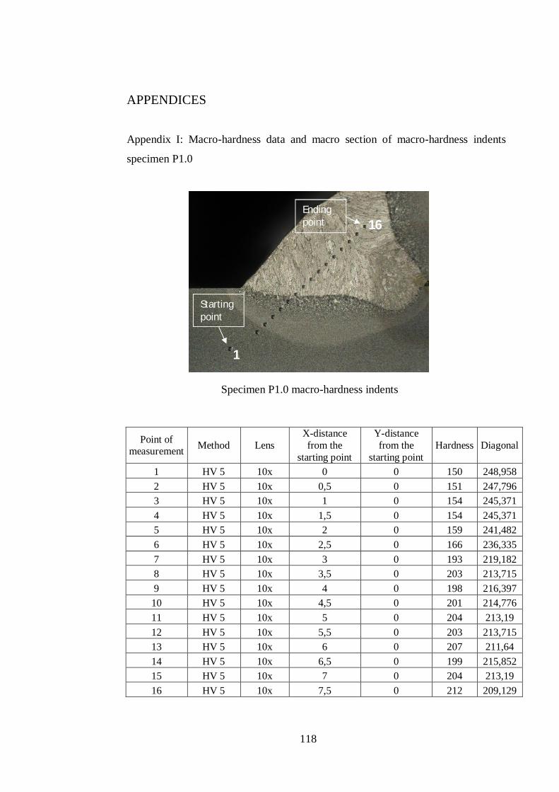
118
APPENDICES
Appendix I: Macro-hardness data and macro section of macro-hardness indents
specimen P1.0
Specimen P1.0 macro-hardness indents
Point of measurement Method Lens
X-distance from the
starting point
Y-distance from the
starting point Hardness Diagonal
1 HV 5 10x 0 0 150 248,958 2 HV 5 10x 0,5 0 151 247,796 3 HV 5 10x 1 0 154 245,371 4 HV 5 10x 1,5 0 154 245,371 5 HV 5 10x 2 0 159 241,482 6 HV 5 10x 2,5 0 166 236,335 7 HV 5 10x 3 0 193 219,182 8 HV 5 10x 3,5 0 203 213,715 9 HV 5 10x 4 0 198 216,397 10 HV 5 10x 4,5 0 201 214,776 11 HV 5 10x 5 0 204 213,19 12 HV 5 10x 5,5 0 203 213,715 13 HV 5 10x 6 0 207 211,64 14 HV 5 10x 6,5 0 199 215,852 15 HV 5 10x 7 0 204 213,19 16 HV 5 10x 7,5 0 212 209,129
16
1
Starting point
Ending point
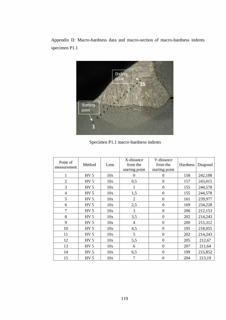
119
Appendix II: Macro-hardness data and macro-section of macro-hardness indents
specimen P1.1
Specimen P1.1 macro-hardness indents
Point of measurement Method Lens
X-distance from the
starting point
Y-distance from the
starting point Hardness Diagonal
1 HV 5 10x 0 0 158 242,188 2 HV 5 10x 0,5 0 157 243,015 3 HV 5 10x 1 0 155 244,578 4 HV 5 10x 1,5 0 155 244,578 5 HV 5 10x 2 0 161 239,977 6 HV 5 10x 2,5 0 169 234,228 7 HV 5 10x 3 0 206 212,153 8 HV 5 10x 3,5 0 202 214,243 9 HV 5 10x 4 0 200 215,312 10 HV 5 10x 4,5 0 195 218,055 11 HV 5 10x 5 0 202 214,243 12 HV 5 10x 5,5 0 205 212,67 13 HV 5 10x 6 0 207 211,64 14 HV 5 10x 6,5 0 199 215,852 15 HV 5 10x 7 0 204 213,19
Starting point
Ending point
1
15
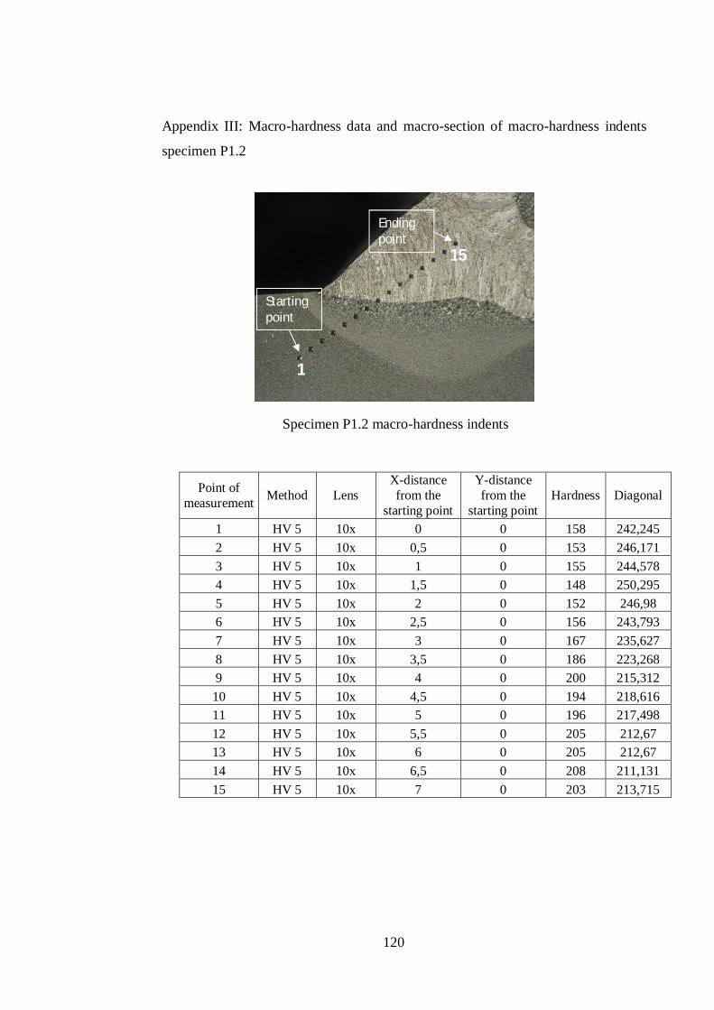
120
Appendix III: Macro-hardness data and macro-section of macro-hardness indents
specimen P1.2
Specimen P1.2 macro-hardness indents
Point of measurement Method Lens
X-distance from the
starting point
Y-distance from the
starting point Hardness Diagonal
1 HV 5 10x 0 0 158 242,245 2 HV 5 10x 0,5 0 153 246,171 3 HV 5 10x 1 0 155 244,578 4 HV 5 10x 1,5 0 148 250,295 5 HV 5 10x 2 0 152 246,98 6 HV 5 10x 2,5 0 156 243,793 7 HV 5 10x 3 0 167 235,627 8 HV 5 10x 3,5 0 186 223,268 9 HV 5 10x 4 0 200 215,312 10 HV 5 10x 4,5 0 194 218,616 11 HV 5 10x 5 0 196 217,498 12 HV 5 10x 5,5 0 205 212,67 13 HV 5 10x 6 0 205 212,67 14 HV 5 10x 6,5 0 208 211,131 15 HV 5 10x 7 0 203 213,715
Starting point
Ending point
1
15
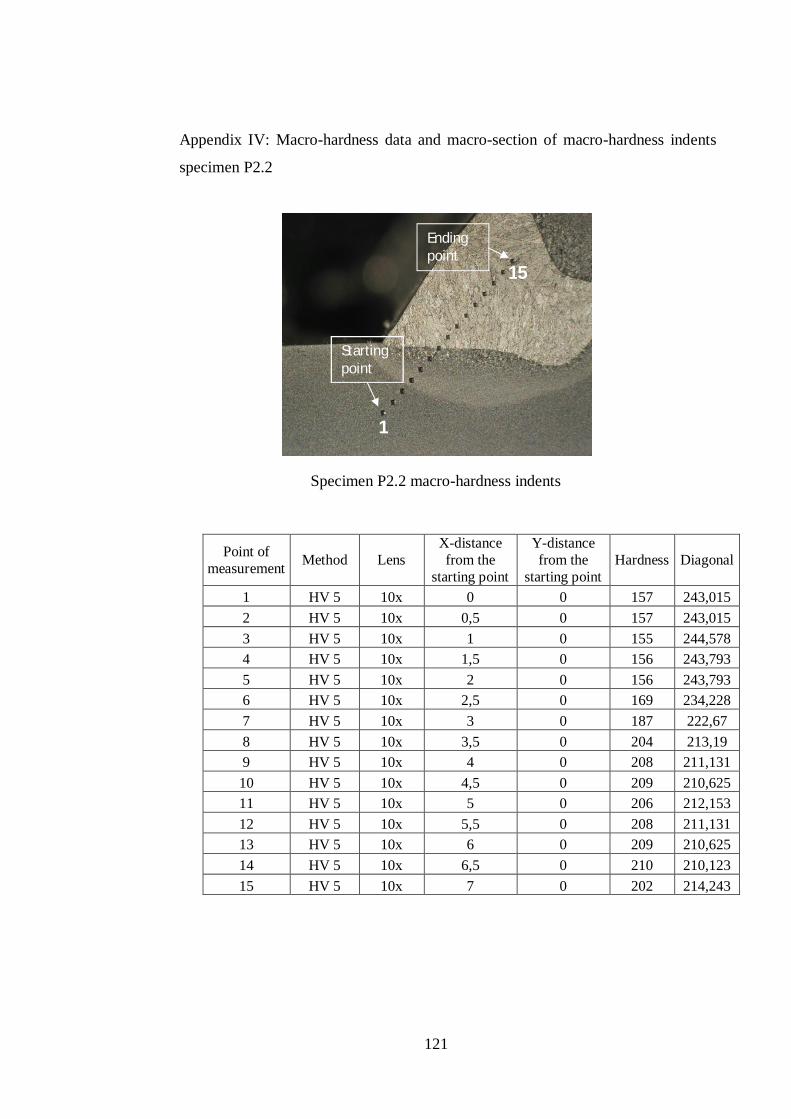
121
Appendix IV: Macro-hardness data and macro-section of macro-hardness indents
specimen P2.2
Specimen P2.2 macro-hardness indents
Point of measurement Method Lens
X-distance from the
starting point
Y-distance from the
starting point Hardness Diagonal
1 HV 5 10x 0 0 157 243,015 2 HV 5 10x 0,5 0 157 243,015 3 HV 5 10x 1 0 155 244,578 4 HV 5 10x 1,5 0 156 243,793 5 HV 5 10x 2 0 156 243,793 6 HV 5 10x 2,5 0 169 234,228 7 HV 5 10x 3 0 187 222,67 8 HV 5 10x 3,5 0 204 213,19 9 HV 5 10x 4 0 208 211,131 10 HV 5 10x 4,5 0 209 210,625 11 HV 5 10x 5 0 206 212,153 12 HV 5 10x 5,5 0 208 211,131 13 HV 5 10x 6 0 209 210,625 14 HV 5 10x 6,5 0 210 210,123 15 HV 5 10x 7 0 202 214,243
Starting point
Ending point
1
15
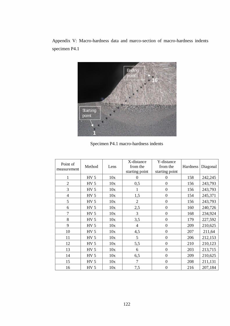
122
Appendix V: Macro-hardness data and marco-section of macro-hardness indents
specimen P4.1
Specimen P4.1 macro-hardness indents
Point of measurement Method Lens
X-distance from the
starting point
Y-distance from the
starting point Hardness Diagonal
1 HV 5 10x 0 0 158 242,245 2 HV 5 10x 0,5 0 156 243,793 3 HV 5 10x 1 0 156 243,793 4 HV 5 10x 1,5 0 154 245,371 5 HV 5 10x 2 0 156 243,793 6 HV 5 10x 2,5 0 160 240,726 7 HV 5 10x 3 0 168 234,924 8 HV 5 10x 3,5 0 179 227,592 9 HV 5 10x 4 0 209 210,625 10 HV 5 10x 4,5 0 207 211,64 11 HV 5 10x 5 0 206 212,153 12 HV 5 10x 5,5 0 210 210,123 13 HV 5 10x 6 0 203 213,715 14 HV 5 10x 6,5 0 209 210,625 15 HV 5 10x 7 0 208 211,131 16 HV 5 10x 7,5 0 216 207,184
Starting point
Ending point
1
16
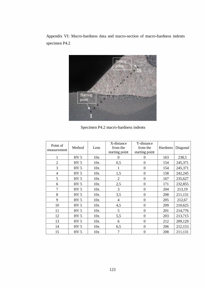
123
Appendix VI: Macro-hardness data and macro-section of macro-hardness indents
specimen P4.2
Specimen P4.2 macro-hardness indents
Point of measurement Method Lens
X-distance from the
starting point
Y-distance from the
starting point Hardness Diagonal
1 HV 5 10x 0 0 163 238,5 2 HV 5 10x 0,5 0 154 245,371 3 HV 5 10x 1 0 154 245,371 4 HV 5 10x 1,5 0 158 242,245 5 HV 5 10x 2 0 167 235,627 6 HV 5 10x 2,5 0 171 232,855 7 HV 5 10x 3 0 204 213,19 8 HV 5 10x 3,5 0 208 211,131 9 HV 5 10x 4 0 205 212,67 10 HV 5 10x 4,5 0 209 210,625 11 HV 5 10x 5 0 201 214,776 12 HV 5 10x 5,5 0 203 213,715 13 HV 5 10x 6 0 212 209,129 14 HV 5 10x 6,5 0 206 212,153 15 HV 5 10x 7 0 208 211,131
Starting point
Ending point
1
15
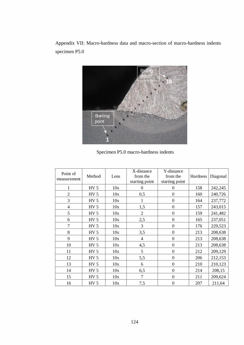
124
Appendix VII: Macro-hardness data and macro-section of macro-hardness indents
specimen P5.0
Specimen P5.0 macro-hardness indents
Point of measurement Method Lens
X-distance from the
starting point
Y-distance from the
starting point Hardness Diagonal
1 HV 5 10x 0 0 158 242,245 2 HV 5 10x 0,5 0 160 240,726 3 HV 5 10x 1 0 164 237,772 4 HV 5 10x 1,5 0 157 243,015 5 HV 5 10x 2 0 159 241,482 6 HV 5 10x 2,5 0 165 237,051 7 HV 5 10x 3 0 176 229,523 8 HV 5 10x 3,5 0 213 208,638 9 HV 5 10x 4 0 213 208,638 10 HV 5 10x 4,5 0 213 208,638 11 HV 5 10x 5 0 212 209,129 12 HV 5 10x 5,5 0 206 212,153 13 HV 5 10x 6 0 210 210,123 14 HV 5 10x 6,5 0 214 208,15 15 HV 5 10x 7 0 211 209,624 16 HV 5 10x 7,5 0 207 211,64
Starting point
Ending point
1
16