Embed Size (px)
Citation preview
Contents lists available at ScienceDirect
Applied Catalysis B: Environmental
journal homepage: www.elsevier.com/locate/apcatb
Review
Powerful combination of MOFs and C3N4 for enhanced photocatalyticperformance
Chong-Chen Wang⁎, Xiao-Hong Yi, Peng WangBeijing Key Laboratory of Functional Materials for Building Structure and Environment Remediation/Beijing Advanced Innovation Center for Future Urban Design, BeijingUniversity of Civil Engineering and Architecture, Beijing, 100044, China
A R T I C L E I N F O
Keywords:Metal-organic frameworksCarbon nitridePhotocatalysisHeterojunctionVisible light
A B S T R A C T
Both pristine metal-organic frameworks (MOFs) and graphitic carbon nitride (g-C3N4) displayed outstandingphotocatalytic performances toward H2 production, CO2 reduction, Cr(VI) reduction and organic pollutantsdegradation. To further enhance their photocatalytic performances under visible light or sunlight irradiation,MOFs and g-C3N4 were combined to construct g-C3N4/MOF heterojunctions with the purpose of overcomingtheir individual disadvantages like fast recombination of pohotogenerated electron-hole pairs. The fabricationmethods, characterizations, photocatalytic performances and the corresponding mechanism of some typical g-C3N4/MOF composites were highlighted. Also, the prospective and challenges of this research field were de-clared.
1. Introduction
Metal-organic frameworks (MOFs), as highly porous crystallinematerials constructed from metal templates and organic linkers, haveattracted increasing attentions due to their potential applications ofcatalysis [1–3], energy gas storage [4–6], gas separation [7–9], ad-sorption toward pollutants [10–18], and so on [19–27]. Especially, arange of MOFs with good photocatalytic activities have been in-vestigated by increasing researchers with great enthusiasm [28–42],since the first work made by García and coworkers on the photo-catalytic phenol photodegradation by adopting MOF-5 as a semi-conductor under UV light irradiation in 2008 [43]. Over the pastdecade, the potential photocatalysis application of MOFs arose growingattentions due to the synergistic effect of their metal centers and or-ganic linkages [29]. As to the photocatalytic activities of MOFs, somepapers provided comprehensive and critical review on their applica-tions to conduct water splitting, CO2 reduction, Cr(VI) reduction andorganic pollutants degradation [28,29,31,41,42,44–52]. However, mostMOFs exhibited efficiently photocatalytic performances only under theUV light illumination, which limited their wide potential applicationsunder visible light or sunlight. Also, some problems like the poor con-ductivity, inadequate stabilities and fast electron-hole recombinationlimited the MOF’s potential use as photocatalysts [28]. Generally, threestrategies like the introduction of -NH2 group, synthesis of Fe-con-taining MOFs and the construction of heterostructures with the aid of
narrow gap semiconductors were adopted to modify MOFs utilize thevisible light or even sunlight [28,29,39,53–59]. However, some ligandsare difficult to introduce -NH2 group at ideal sites, or the introduced-NH2 group would change the ligands’ original coordination mode.Therefore, it is not always feasible to modify functional groups on or-ganic ligands. As well, most Fe-containing MOFs displayed good pho-tocatalytic performance under visible light irradiation due to the ex-tensive Fe-O (iron-oxo) clusters [58,59]. However, the diversity ofMOFs required more metal ions besides Fe to be selected as templates.The third strategy to construct heterostructures between narrow gapsemiconductors and MOFs was more preferred to excite their photo-catalytic activity under visible light or sunlight [28,29,60].
Another star photocatalyst is polymeric graphite-like C3N4 (g-C3N4),a metal-free semiconductor, which is an outstanding photocatalyst dueto: (1) π-conjugated electronic structures [61,62]; (2) the band gap ofca. 2.7 eV (conduction band, ca. -1.1 V vs. NHE; valence band, ca. 1.6 Vvs. NHE), implying it can absorb visible light [63,64]; (3) its out-standing chemical stability in solutions of any pH under light illumi-nation along with its excellent thermal stability [65,66]; (4) its low costdue to that it can be produced from relatively cheap N containing or-ganic precursors like urea, melamine and so on [67–71]; and (5) con-venient and facile synthesis routes [72–80]. Therefore, g-C3N4 has beenwidely applied in diverse fields like catalysis [67,81,82], water splitting[83–86], CO2 reduction [83,87,88], Cr(VI) reduction [89–93], andphotocatalytic degradation of organic pollutants [94–96]. However, the
https://doi.org/10.1016/j.apcatb.2019.01.091Received 16 November 2018; Received in revised form 9 January 2019; Accepted 31 January 2019
⁎ Corresponding author.E-mail address: [email protected] (C.-C. Wang).
Applied Catalysis B: Environmental 247 (2019) 24–48
Available online 02 February 20190926-3373/ © 2019 Elsevier B.V. All rights reserved.
T
further practical application of pristine g-C3N4 also suffered from itsintrinsic drawbacks: (i) its easy recombination of photogeneratedelectron-hole pairs due to the hybridization of the N 2p and C 2p statesin the CB and unavoidably disordered structure or defects [6,97,98]; (ii)limited visible light utilization due to its moderate bandgap
(Eg= 2.7 eV, corresponding to an optical wavelength of 460 nm); (iii)its low surface area resulted from its bulk structure [99–101], and (iv)poor hydrophily. Some strategies were adopted to improve the photo-catalytic performance of g-C3N4, which could be classified into elec-tronic structure modification [102,103], nanostructure design [104],
Table 1The photocatalytic performances of some binary MOF/g-C3N4 composites.
Composites Preparation method Applications Ref.
g-C3N4/ZIF-8 In-situ deposition of ZIF-8 from its precursors on the prepared g-C3N4 nanotubes CO2 reduction [109]g-C3N4/ZIF-8 In-situ deposition of ZIF-8 nanoparticles from its precursors on the prepared g-C3N4. H2 production [110]g-C3N4/ZIF-8 In-situ deposition of ZIF-8 from its precursors on the prepared g-C3N4. Adsorption and photocatalytic degradation toward
tetracycline[111]
ZIF-8/g-C3N4 In-situ deposition of ZIF-8 from its precursors on the prepared g-C3N4. Rhodamine B (RhB) degradation [112]g-C3N4/UiO-66 Annealing the mixture of prepared UiO-66 octahedrons and g-C3N4 H2 production [107]g-C3N4/UiO-66 (i) The carbon nitride nanosheets (CNNS) were prepared by a liquid exfoliation route
from bulk carbon nitride (CN) in water. (ii) The CNNS were coated on as-prepared UiO-66 via electrostatic interactions.
CO2 reduction [108]
g-C3N4/UiO-66 Solvothermal deposition of UiO-66 on the prepared g-C3N4 RhB degradation [113]g-C3N4/UiO-66 thermal treating the mixture of UiO-66 octahedrons and g-C3N4 sheets Methylene blue (MB) degradation [114]g-C3N4/MIL-53(Al) Solvothermal deposition of MIL-53(Al) on the prepared g-C3N4 RhB degradation [115]g-C3N4/MIL-53(Fe) Solvothermal deposition of MIL-53(Fe) on the prepared g-C3N4 Cr(VI) reduction [9]g‐C3N4/MIL‐53(Fe) Grinding between prepared MIL-53(Fe) and g‐C3N4 H2 production [116]g-C3N4/MIL-100(Fe) In-situ chemical protonation of g-C3N4 and dip-coating between the prepared MIL-
100(Fe) and g-C3N4 mixture via thermal treatment.RhB and MB degradation, along with the oxidativedenitrogenation towards pyridine
[117]
C3N4/MIL-100(Fe) In-situ deposition of MIL-100(Fe) nanoparticles from its precursors on the preparedcarbon nitride nano-sheet (CNNS).
RhB degradation [118]
MIL-100(Fe)/g-C3N4 Ball-milling and thermal treatment ofprepared g-C3N4 and MIL-100(Fe) mixture. Cr(VI) reduction [119]g-C3N4/NH2-MIL-101(Fe) In-situ deposition of MIL-101(Fe) from its precursors on the prepared g‐C3N4 Cr(VI) reduction and methyl orange (MO)
degradation[120]
g-C3N4/MIL-101(Fe) In-situ hydrothermal synthesis of MIL-101(Fe), which can be covered by the prepared g-C3N4.
Bisphenol A (BPA) degradation. [121]
g-C3N4/MIL-125(Ti) In-situ deposition of MIL-125(Ti) from its precursors on the prepared g‐C3N4 RhB degradation [122]g-C3N4/CuBTC In-situ deposition of CuBTC from its precursors on the prepared g‐C3N4 Dimethyl chlorophosphate (DMCP) degradation [123]g-C3N4/NH2-MIL-88B(Fe) In-situ deposition of NH2-MIL-88B(Fe) from its precursors on the prepared g‐C3N4. MB degradation [124]g-C3N4/MIL-88B(Fe) In-situ fabrication of MIL-88B(Fe) from its precursor on the prepared g‐C3N4
nanosheets.MB degradation and Cr(VI) reduction. [125]
g-C3N4/BUC-21 Ball-milling of prepared g-C3N4 and BUC-21. Cr(VI) reduction [126]
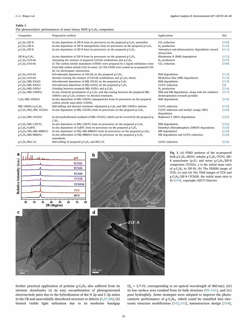
Fig. 1. (a) PXRD patterns of the as-preparedbulk g-C3N4 (BCN), tubular g-C3N4 (TCN), ZIF-8 nanocluster (p-Z), and series g-C3N4/ZIF-8composites (TCNZx, x is the initial mass ratioof g-C3N4 to ZIF-8); (b) The FESEM image ofTCN; (c) and (d) The TEM images of TCN andg-C3N4/ZIF-8 (TCNZ8, the initial mass ratio is8) [109], copyright (2017) Elsevier.
C.-C. Wang et al. Applied Catalysis B: Environmental 247 (2019) 24–48
25
crystal structure engineering [105] and heterostructure construction[106].
It is generally deemed that a desired photocatalyst should simulta-neously possess the merits of suitable bandgap, proper hydrophily,large surface area and cost-effective. To overcome the drawbacks ofMOFs and g-C3N4, and to achieve the merits of ideal photocatalysts forenhanced photocatalytic performances, the fabrication of binary g-C3N4/MOF and ternary g-C3N4/MOF/X (X is one of semiconductorphotocatalysts) heterojunction composites in both macroscale and na-noscale has been proved as an effective strategy. In detail, the con-struction of heterostructure can achieve the following advantages: (i)high surface area that can enhance reactant/catalyst interactions viaincreasing adsorption performance toward targeted models; (ii) en-hanced separation rates of photoinduced electron-hole resulted fromthat the formed junction can accelerate charge transfer across the in-terface and shortens the charge transport distance; (iii) the uniform
distribution of photocatalytically active sites, and (iv) broadening thelight spectrum to visible light region. Importantly, the π-π interactionsbetween the massive aromatic rings of organic ligands in MOFs and thetriazine rings of g-C3N4, along with abundant surface electrostatic in-teractions, will help them achieve close contact, heterojunction con-struction as well as effective electron transfer [107,108].
2. The status of g-C3N4/MOF binary photocatalysts
Some representative MOFs like ZIF-8, MIL-53, MIL-101, MIL-125,HKUST-1, MOF-5, and UiO-66 exhibited excellent properties and var-ious potential applications [19]. Up to now, several MOFs (ZIF-8, UiO-66, MIL-53, MIL-100, MIL-101, MIL-125, CuBTC, MIL-88B and BUC-21)and g-C3N4 with different morphologies (nanosheet, nanorod and na-notube) were combined to construct some binary heterojunction com-posites (Table 1), which can take advantage of the complementary
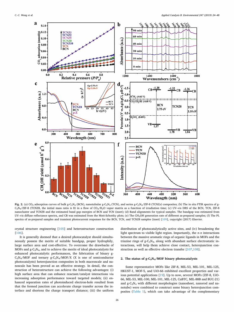
Fig. 2. (a) CO2 adsorption curves of bulk g-C3N4 (BCN), nanotubular g-C3N4 (TCN), and series g-C3N4/ZIF-8 (TCNZx) composites; (b) The in situ FTIR spectra of g-C3N4/ZIF-8 (TCNZ8, the initial mass ratio is 8) in a flow of CO2/H2O vapor matrix as a function of irradiation time; (c) UV–vis DRS of the BCN, TCN, ZIF-8nanocluster and TCNZ8 and the estimated band gap energies of BCN and TCN (inset); (d) Band alignments for typical samples. The bandgap was estimated fromUV–vis diffuse reflectance spectra, and CB was estimated from the Mott-Schottky plots; (e) The CH3OH generation rate of different as-prepared samples; (f) The PLspectra of as-prepared samples and transient photocurrent responses for the BCN, TCN, and TCNZ8 samples (inset) [109], copyright (2017) Elsevier.
C.-C. Wang et al. Applied Catalysis B: Environmental 247 (2019) 24–48
26
merits of MOFs and g-C3N4 and overcome their disadvantages. In thissection, the heterostructure composites constructed between someMOFs (like ZIF-8, UiO-66(-NH2), MIL-53(Al/Fe) and MIL-100(Fe)) andg-C3N4 were selected to highlight their fabrication methods, char-acterizations, photocatalytic performances and mechanism.
2.1. g-C3N4/ZIF-8
ZIF-8 [Zn(2-methylimidazole)2·2H2O], constructed from 2-methyi-midazolate organic ligands and Zn2+ center ions, exhibits outstandingthermal/chemical stability [127], and large BET specific surface area(SSA) (≈ 2000m2/g) [128]. ZIF-8 was widely used in various fieldsincluding but not limited to gas storage [129,130], separation [131],adsorptive removal of pollutants [132], catalysis [133,134], and sen-sing [135]. In 2014, ZIF-8 was selected as photocatalyst to conduct MBdegradation under UV light irradiation, in which the degradationpathway and mechanism were proposed and verified [30]. Subse-quently, some ZIF-8 based photocatalysts like MoO3@ZIF-8 [136],TiO2@ZIF-8 [137], Ag/AgCl@ZIF-8 [138,139], Cd0.5Zn0.5S@ZIF-8[140], ZnO@ZIF-8 [141] were fabricated to achieve enhanced photo-catalytic performances toward CO2 reduction, Cr(VI) reduction, andorganic pollutants degradation.
Recently, ZIF-8 and g-C3N4 with different morphologies were fab-ricated and composited to combine their both merits, aiming to en-hance their photocatalytic performances. Considering that the g-C3N4
nanotube (TCN) thermally prepared via a rolling-up mechanism canaccomplish fast photo-response and reproducible photoconductivity[142], suitable amount of transparent ZIF-8 nanocluster [143] was in-troduced to decorate the well-designed TCN to further increase CO2
capture and adsorption selectivity without decreasing light absorptioncapacity [109]. In the powder X-ray diffraction (PXRD) patterns ofprepared TCN/ZIF-8 (TCNZx, x is related to the initially designed massratio of TCN to ZIF-8) composites, the strong diffraction peak at 27.4°(d=0.326 nm) was attributed to the inter-planar stacking of con-jugated aromatic systems, corresponding to the (002) plane of bothtubular and bulk g-C3N4 [144]. It was worthy to noting that a minordiffraction peak at ca. 17.4° (d=0.490 nm) of TCN and ca. 13.0°(d=0.681 nm) of bulk g-C3N4 implied that they was built up from thes-triazine based building units and tri-s-triazine based building units,
respectively [74,142]. The noticeable PXRD peaks of ZIF-8 nanoclusterscould be detected in the PXRD patterns of TCNZ composites when thecontent of decorated ZIF-8 was high enough (like TCNZ1), indicatingthat the ZIF-8 nanocluster could assembly on the surface of TCNwithout altering its surface. The successful fabrication of the TCNZcomposites was further confirmed by their microstructure observed byboth filed-emission scanning electron microscopy (FESEM) and trans-mission electron microscopy (TEM). As illustrated in the Fig. 1, thetubular morphology of TCN was maintained well after the decoration ofsuitable ZIF-8 nanocluster. As well, most pores of the TCN were filled byZIF-8 nanocluster, resulting into the smoother surface. It was reportedthat the thin tubular structure would favor the charge separation andthe transportation of reactants/products [145,146]. Also, the reactionpathway and dynamics of the photocatalytic CO2 reduction were es-sentially controlled by the adsorption of CO2 onto the photocatalystsurface [147]. As demonstrated in Fig. 2a and b, the incorporation ofZIF-8 nanocluster into the TCN led to the improved CO2 adsorptioncapacity. Furthermore, the CO2 adsorption capacities of the TCNZcomposites increased with the increase of ZIF-8 nanocluster contents.As illustrated in Fig. 2c, the decoration of transparent ZIF-8 nanoclusterover the surface of TCN didn’t lead to inhabitation of visible light ab-sorption ability. All the conduction band (CB) values facilitate thethermodynamically photocatalytic CO2 reduction (Fig. 2d), however,taking electrical conductivity (flat band potential) and CB potential intoaccount, the grafted ZIF-8 cluster onto TCN lead to both positive andnegative influences toward the photocatalytic performance. Accordingto the in-situ monitor of FTIR (Fig. 2b), the CH3OH formation from thephotocatalytic CO2 reduction can be described as typical two-electronand two-proton reaction pathway, i.e. (CO2→HCOOH→HCHO→-CH3OH) [148]. As illustrated in Fig. 2e, the photocatalytic CO2 re-duction into CH3OH can be significantly improved by the combinationbetween TCN and ZIF-8 nanoparticles, in which the CH3OH productionover TCNZ8 is three times higher than that over TCN. Although the CO2
adsorption capacity increased with the increase of ZIF-8 content intothe TCN composites, the surface charge transfer would be inhibited bythe increasing introduction of ZIF-8 resulting from its weak electricalconductivity, which was affirmed by the determination of photo-luminescence (PL) spectra and transient photocurrent response. In PLspectra as shown in Fig. 2e, the weak emission peak at ca. 400 nm was
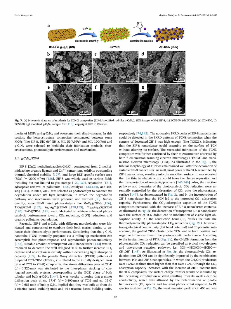
Fig. 3. (a) Schematic diagram of synthesis for ZCN-X composites (ZIF-8/modified rod-like g-C3N4); SEM images of (b) ZIF-8, (c) ZCN100, (d) ZCN200, (e) ZCN400, (f)ZCN800, (g) modified g-C3N4 sample CN [110], copyright (2018) Elsevier.
C.-C. Wang et al. Applied Catalysis B: Environmental 247 (2019) 24–48
27
assigned to TCN, much different from the strong emission peak at ca.450 nm of bulk g-C3N4 (BCN), which implied that the unique tubularstructure favored the charge separation. Noticeably, the determinationresults of both PL and transient photocurrent response of TCNZ com-posites revealed that their photocatalytic performance is lower thanthat of TCN. However, the combination of enhanced adsorption andphotocatalysis led to that the TCNZ composite photocatalyst exhibitedimproved photocatalytic activity for the CO2 reduction, reaching0.75 μmol h−1 g−1 under mild reaction condition. Two additionalmerits of ZIF-8 made it an outstanding candidate for fabricating ZIF-8/g-C3N4 heterojunction for photocatalytic CO2 reduction: (i) the trans-parence of ZIF-8 will not suppress too much the light harvesting ca-pacity; (ii) the gas adsorption selectivity within ZIF-8 made it can ad-sorb the reactant CO2 effectively, but not be affinitive to the reductionproducts like CH4 and CH3OH. This work provides a strategy to fabri-cate outstanding photocatalysts by combining the merits of semi-conductor nanostructure and the surface of MOFs.
Considering the structural merits of g-C3N4 and ZIF-8, Xiaofei Yangand coworkers proposed a two-step strategy (electrostatically-drivenassembly process and thermal treatment process) to prepare g-C3N4/ZIF-8 hybrids (ZCN) via anchoring polyhedral ZIF-8 nanoparticles ontothe surface of rod-like g-C3N4 [110]. As illustrated in Fig. 3a, the pre-pared porous rod-like g-C3N4 nanorods with negative surface charge(zeta potential being −48mV) were interacted with Zn2+ to form the
intermediates, which were further reacted with 2-methylimidazole toaccomplish in-situ fabrication of polyhedral ZIF-8 nanoparticles ontorod-like g-C3N4. The successful fabrication of g-C3N4/ZIF-8 (ZCN) hy-brids was further confirmed by FE-SEM (Fig. 3b–g), powder X-ray dif-fraction (PXRD) and X-ray photoelectron spectroscopy (XPS).
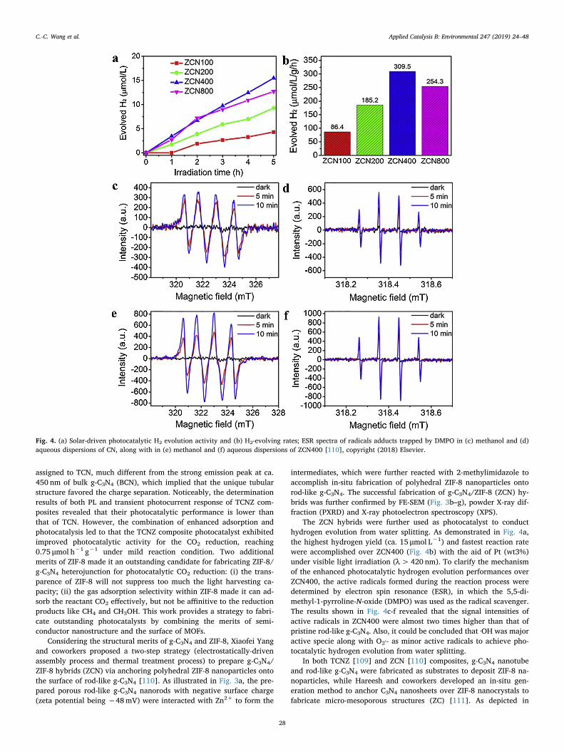
The ZCN hybrids were further used as photocatalyst to conducthydrogen evolution from water splitting. As demonstrated in Fig. 4a,the highest hydrogen yield (ca. 15 μmol L−1) and fastest reaction ratewere accomplished over ZCN400 (Fig. 4b) with the aid of Pt (wt3%)under visible light irradiation (λ>420 nm). To clarify the mechanismof the enhanced photocatalytic hydrogen evolution performances overZCN400, the active radicals formed during the reaction process weredetermined by electron spin resonance (ESR), in which the 5,5-di-methyl-1-pyrroline-N-oxide (DMPO) was used as the radical scavenger.The results shown in Fig. 4c-f revealed that the signal intensities ofactive radicals in ZCN400 were almost two times higher than that ofpristine rod-like g-C3N4. Also, it could be concluded that ·OH was majoractive specie along with O2·- as minor active radicals to achieve pho-tocatalytic hydrogen evolution from water splitting.
In both TCNZ [109] and ZCN [110] composites, g-C3N4 nanotubeand rod-like g-C3N4 were fabricated as substrates to deposit ZIF-8 na-noparticles, while Hareesh and coworkers developed an in-situ gen-eration method to anchor C3N4 nanosheets over ZIF-8 nanocrystals tofabricate micro-mesoporous structures (ZC) [111]. As depicted in
Fig. 4. (a) Solar-driven photocatalytic H2 evolution activity and (b) H2-evolving rates; ESR spectra of radicals adducts trapped by DMPO in (c) methanol and (d)aqueous dispersions of CN, along with in (e) methanol and (f) aqueous dispersions of ZCN400 [110], copyright (2018) Elsevier.
C.-C. Wang et al. Applied Catalysis B: Environmental 247 (2019) 24–48
28
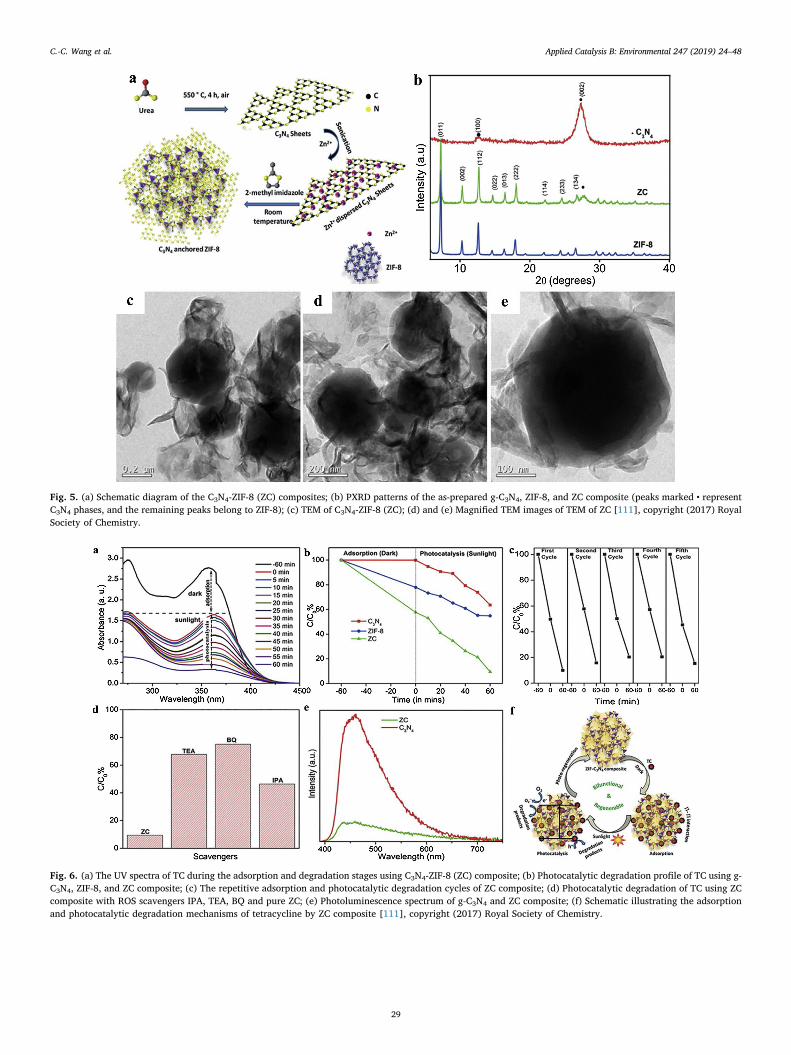
Fig. 5. (a) Schematic diagram of the C3N4-ZIF-8 (ZC) composites; (b) PXRD patterns of the as-prepared g-C3N4, ZIF-8, and ZC composite (peaks marked • representC3N4 phases, and the remaining peaks belong to ZIF-8); (c) TEM of C3N4-ZIF-8 (ZC); (d) and (e) Magnified TEM images of TEM of ZC [111], copyright (2017) RoyalSociety of Chemistry.
Fig. 6. (a) The UV spectra of TC during the adsorption and degradation stages using C3N4-ZIF-8 (ZC) composite; (b) Photocatalytic degradation profile of TC using g-C3N4, ZIF-8, and ZC composite; (c) The repetitive adsorption and photocatalytic degradation cycles of ZC composite; (d) Photocatalytic degradation of TC using ZCcomposite with ROS scavengers IPA, TEA, BQ and pure ZC; (e) Photoluminescence spectrum of g-C3N4 and ZC composite; (f) Schematic illustrating the adsorptionand photocatalytic degradation mechanisms of tetracycline by ZC composite [111], copyright (2017) Royal Society of Chemistry.
C.-C. Wang et al. Applied Catalysis B: Environmental 247 (2019) 24–48
29
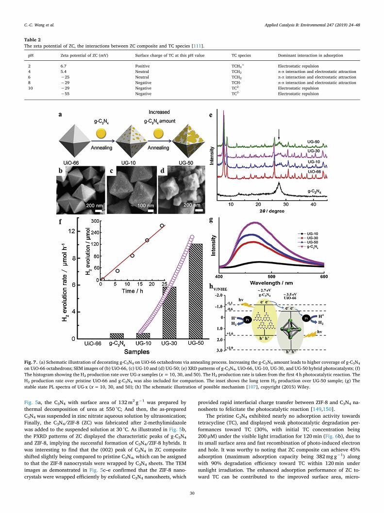
Fig. 5a, the C3N4 with surface area of 132m2 g−1 was prepared bythermal decomposition of urea at 550 °C; And then, the as-preparedC3N4 was suspended in zinc nitrate aqueous solution by ultrasonication;Finally, the C3N4/ZIF-8 (ZC) was fabricated after 2-methylimidazolewas added to the suspended solution at 30 °C. As illustrated in Fig. 5b,the PXRD patterns of ZC displayed the characteristic peaks of g-C3N4
and ZIF-8, implying the successful formation of C3N4/ZIF-8 hybrids. Itwas interesting to find that the (002) peak of C3N4 in ZC compositeshifted slightly being compared to pristine C3N4, which can be assignedto that the ZIF-8 nanocrystals were wrapped by C3N4 sheets. The TEMimages as demonstrated in Fig. 5c–e confirmed that the ZIF-8 nano-crystals were wrapped efficiently by exfoliated C3N4 nanosheets, which
provided rapid interfacial charge transfer between ZIF-8 and C3N4 na-nosheets to felicitate the photocatalytic reaction [149,150].
The pristine C3N4 exhibited nearly no adsorption activity towardstetracycline (TC), and displayed weak photocatalytic degradation per-formances toward TC (30%, with initial TC concentration being200 μM) under the visible light irradiation for 120min (Fig. 6b), due toits small surface area and fast recombination of photo-induced electronand hole. It was worthy to noting that ZC composite can achieve 45%adsorption (maximum adsorption capacity being 382mg g−1) alongwith 90% degradation efficiency toward TC within 120min undersunlight irradiation. The enhanced adsorption performance of ZC to-ward TC can be contributed to the improved surface area, micro-
Table 2The zeta potential of ZC, the interactions between ZC composite and TC species [111].
pH Zeta potential of ZC (mV) Surface charge of TC at this pH value TC species Dominant interaction in adsorption
2 6.7 Positive TCH3+ Electrostatic repulsion
4 5.4 Neutral TCH2 π-π interaction and electrostatic attraction6 −25 Neutral TCH2 π-π interaction and electrostatic attraction8 −29 Negative TCH- π-π interaction and electrostatic attraction10 −29 Negative TC2- Electrostatic repulsion
−55 Negative TC2- Electrostatic repulsion
Fig. 7. (a) Schematic illustration of decorating g-C3N4 on UiO-66 octahedrons via annealing process. Increasing the g-C3N4 amount leads to higher coverage of g-C3N4
on UiO-66 octahedrons; SEM images of (b) UiO-66, (c) UG-10 and (d) UG-50; (e) XRD patterns of g-C3N4, UiO-66, UG-10, UG-30, and UG-50 hybrid photocatalysts; (f)The histogram showing the H2 production rate over UG-x samples (x=10, 30, and 50). The H2 production rate is taken from the first 4 h photocatalytic reaction. TheH2 production rate over pristine UiO-66 and g-C3N4 was also included for comparison. The inset shows the long term H2 production over UG-50 sample; (g) Thestable state PL spectra of UG-x (x=10, 30, and 50); (h) The schematic illustration of possible mechanism [107], copyright (2015) Wiley.
C.-C. Wang et al. Applied Catalysis B: Environmental 247 (2019) 24–48
30
mesoporous structure and powerful π-π stacking interactions betweenTC species and ZC composite (as listed in Table 2). It was found inFig. 6a that the maximum absorption peak at 357 nm of TC was slightlymoved to 364 nm, which might result from the strong interactions be-tween TC and ZC composites [151].
To clarify the possible mechanism of ZC composite’s photocatalyticreaction, the reactive species (RS) trapping experiments along with thephotoluminescence determination were carried out. Trithanolamine(TEA), benzoquinone (BQ) and isopropyl alcohol (IPA) were used asscavengers to capture holes, superoxide anions and hydroxyl radicals,respectively. As illustrated in Fig. 6d, the photocatalytic degradationperformances were inhibited significantly with the addition of thesethree scavengers, following the order of BQ > TEA > IPA. In order toinvestigate the recombination rate of photo-produced holes and elec-trons, the photoluminescences (PL) of C3N4 and ZC composite weredetected, in which the PL emission intensity of ZC at 460 nm due toband-band stacking of C3N4 decreased significantly, comparing to theindividual C3N4 (Fig. 6e). In all, the micro-mesopore structure of ZCcomposite facilitated their enhanced adsorption and photocatalyticperformances due to that they provided adequate active sites. Theschematic illustration of the adsorption and photocatalytic degradationmechanisms of C3N4-ZIF-8 (ZC) composite toward tetracycline wasdepicted in Fig. 6f. Upon the irradiation of sunlight, the excited elec-trons in the lowest unoccupied molecular orbital (LUMO) (-3.41 eV) ofZIF-8 are transferred to the relatively low CB (-1.32 eV) of C3N4, whichreact with O2 to form superoxide radicals (·O2
−) to further degrade TCmolecules. Also, the holes in the highest occupied molecular orbital(HOMO) (1.68 eV) of ZIF-8 decompose the TC molecules directlywithout transporting to the VB (1.62 eV) of C3N4 due to their close VBpotentials. Due to the synergy effect between these two constitutes, therecombination between the excited holes and electrons is inhibited, andthe photocatalytic ability is improved. This bifunctional C3N4/ZIF-8composite with adsorption and photocatalysis activities provides a goodsolution to achieve efficient removal of pollutants like tetracyclinewithout the input of additional energy/chemicals and free of secondarytreatment. Generally, the adsorption is a spontaneous process, hencedesorption is achieved with the aid of chemical or energy input [10]. In
this work, the ZC composite as adsorbent could be regenerated byphotocatalytic degradation toward TC, which provided a new strategyto achieve re-generality of adsorbents. Also, ZC composite is stable andcan be reused for long time, which can be affirmed by five runs’ re-cyclability (Fig. 6c).
2.2. g-C3N4/UiO-66
UiO-66 is constructed from Zr6O4(OH)4 octahedra linked by 1,4-benzene-dicarboxylate (BDC) linker, which possessed very high surfacearea (1147m2/g) and ultrahigh thermal stability and chemical stabilityresulted from their strong Zr-O bond and high coordination number ofZr(IV) [152–156]. Considering its merits like exceptional porosity, highinternal surface area and the active Zr-O cluster, UiO-66 had beenwidely used in various research fields like catalysis [157,158], photo-catalysis [159–164], gas adsorption & separation [165–169], adsorptiveremoval of organic pollutants in wastewater [170]. The photocatalyticactivities of UiO-66 and UiO-66-NH2 were firstly reported to accom-plish H2 production from methanol or the mixture of methanol/H2Oupon the irradiation of 300 nm light [161]. Recently, Li et al. reviewedthe argument of the UiO-66-NH2’s photocatalytical activity origin[164]. Considering the finding of ESR signal corresponding to Zr3+, Liand coworkers along with Long and coworkers believed that the photo-induced Zr3+ generated via ligand-metal-charge-transfer (LMCT) re-sulted into the UiO-66-NH2’s excellent phocatalytic performance[159,162]. While, Matsuoka and coworkers as well as Gascon andcoworkers insisted that no Zr3+ can be produced in UiO-66-NH2 due tothe highly negative redox potential of Zr-O clusters [171] and purelyligand-based highest occupied crystal orbital (HOCO) - lowest un-occupied crystal orbital (LUCO) transition [172]. Although furtherstudies are urgently needed to clarify the pending debate on the originof UiO-66-NH2’s photocatalytic activity, more and more researchersintroduced it into their photocatalysis system to achieve appealingphotocatalytic performance.
Considering that both UiO-66 and g-C3N4 displayed limited photo-catalytic performances due to their quick charge recombination andrestricted light adsorption ability [159–164,172,173], Yuan and
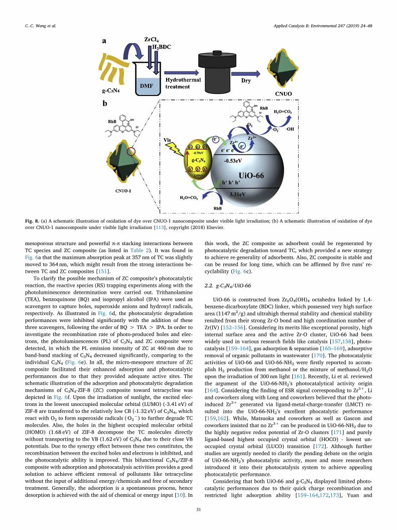
Fig. 8. (a) A schematic illustration of oxidation of dye over CNUO-1 nanocomposite under visible light irradiation; (b) A schematic illustration of oxidation of dyeover CNUO-1 nanocomposite under visible light irradiation [113], copyright (2018) Elsevier.
C.-C. Wang et al. Applied Catalysis B: Environmental 247 (2019) 24–48
31
coworkers developed quasi-polymeric g-C3N4/UiO-66 hybrids (UG-x, x= the mass ratio of g-C3N4 in the hybrids) to achieve enhanced pho-tocatalytic hydrogen production via water splitting [107]. As illustratedin Fig. 7a, the UG-x hybrids were prepared via annealing the matrix ofUiO-66 and g-C3N4 with different mass ratio in argon atmosphere. ThePXRD, SEM, TEM and HR-TEM confirmed the formation of g-C3N4/UiO-66 hybrids, in which the clear interface between g-C3N4 and UiO-66facilitated the rapid charge transfer between these two components(Fig. 7a–e). The UG-X hybrids demonstrated enhanced photocatalyticH2 production under the conditions of ascorbic acid (0.1M, pH=4) asscavenger and Pt as co-catalyst upon visible light illumination, in whichthe H2 production ratios of UG-10 and UG-50 were 11 and 17 timeshigher than that of individual g-C3N4. However, the excessive g-C3N4
into hybrid could result into declined H2 production rate due to “cov-ering effect”. The UG-x composite (like UG-50) was stable to
accomplish long-term and efficient H2 production for 24 h (Fig. 7f). Thesteady-state photoluminescence (PL) determination revealed that theintroduction of UiO-66 led to the PL emission (ca. 460 nm of g-C3N4)quench, as shown in Fig. 7g, implying a rapid charge transfer over UG-xhybrids. It was further affirmed by the decreasing lifetime of chargecarrier with the increase amount of UiO-66 (2.88 ns for g-C3N4 and2.26 ns for UG-50). The energy position of CB edge of g-C3N4 (-1.1 V vsNHE at pH=7.0) was more negative than that of UiO-66 (-0.6 V vsNHE at pH=7.0), resulting into that visible-light-induced electrons ing-C3N4 transferred to UiO-66 across the interfaces between these twocomponents. With the aid of Pt particles, the accumulated electrons ing-C3N4 and UiO-66 reduced the H+ into H2, and the ascorbic acidconsumed the holes in g-C3N4 to enhance the photocatalytic H2 pro-duction, as illustrated in Fig. 7h.
Liu and coworkers developed a facile solvothermal method (Fig. 8a)
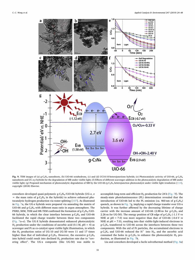
Fig. 9. TEM images of (a) g-C3N4 nanosheets, (b) UiO-66 octahedrons, (c) and (d) UC10:10 heterojunctions hybrids; (e) Photocatalytic activity of UiO-66, g-C3N4
nanosheets and UC x:y hybrids for the degradation of MB under visible light; (f) Effects of different scavenger addition in the photocatalytic degradation of MB undervisible light; (g) Proposed mechanism of photocatalytic degradation of MB by the UiO-66/g-C3N4 heterojunction photocatalyst under visible light irradiation [114],copyright (2018) Elsevier.
C.-C. Wang et al. Applied Catalysis B: Environmental 247 (2019) 24–48
32
to fabricate g-C3N4/UiO-66 nanohybrids (CNUO-x) [113], which wereused to conduct enhanced photocatalytic RhB degradation under visiblelight irradiation. This work highlighted the possible photocatalyticmechanism of CNUO-x (like CNUO-1) toward RhB degradation, as
illustrated in Fig. 8b. (i) The adsorbed H2O can be oxidized into ·OHradicals by photo-generated holes, due to that the VB of UiO-66(+3.31 eV vs NHE) is more positive than the standard electrode po-tential of ·OH/H2O (+2.4 eV vs NHE). (ii) The photo-generated holeson CB of g-C3N4 (-0.79 eV vs NHE) are transferred to the CB of UiO-66(-0.53 eV vs NHE), which inhibited the recombination of photo-gener-ated holes/electrons to enhance the photocatalytic activities. (iii) Thephoto-generated electrons on VB of UiO-66 can reduce O2 into ·O2
−
radicals. (iv) The RhB molecules adsorbed on the surface of CNUO-1upon the irradiation of visible light can be excited to form RhB*, whichcan be degraded by active species like h+, ·O2
− or ·OH. The electronsfrom RhB and g-C3N4 can reduce Zr4+ in the Zr-O cluster of UiO-66 intoZr3+, and the Zr3+ can be oxidized to Zr4+ [174]. Hence, h+, ·O2
− or·OH can decompose RhB and RhB·+, following the Reactions (1)–(6).
RhB+hυ→ RhB* → RhB·+ + e− (1)
g-C3N4 + hυ→ g-C3N4 (h+ + e−) (2)
UIO-66 + e− →Zr3+ - UIO-66 (3)
Zr3+ - UIO-66 +O2 → Zr4+ - UIO-66 + ·O2− (4)
O2−/·OH+RhB/ RhB·+ → degradation product (5)
h+ + RhB/ RhB·+ → degradation products (6)
Zou et al. prepared UiO-66/g-C3N4 heterojunction UC x:y(x:y=2:10, 5:10, 10:10, 10:5 and 10:2, corresponding to the addedamount of g-C3N4 being 83.3, 66.7, 50.0, 33.3, and 16.7 wt%) photo-catalyst via a facile annealing the matrix of UiO-66 and g-C3N4 na-nosheet [114], which was affirmed by TEM, XRD, XPS, TG-DSC, UV–visDRS, PL and BET. The TEM images shown in Fig. 9a–d revealed that theas-prepared g-C3N4 nanosheet is thin and flat, in which some in-planeholes with size ranging 60–90 nm contributed the increasing specificsurface area. The UiO-66 octahedrons were coated on the g-C3N4 sheetsafter annealing at 350 °C for 2 h in air atmosphere, and both UiO-66 andg-C3N4 were stable to keep their morphology structures during theannealing process. The photocatalytic degradation performances ofUiO-66/g-C3N4 heterojunction UC x:y toward MB under the irradiationof visible light was displayed in Fig. 9e. It was found that UC 10:10could achieve best photocatalytic degradation performance, which re-sulted from the UiO-66’s internal porous structure to facilitate the ad-sorption of MB and the formed heterojunction to inhibit the re-combination of photo-generated holes/electrons. In this work, TOC wasdetermined to test the mineralization of MB using UC-10:10 as photo-catalyst. The results revealed that 72% TOC removal was accomplishedafter 240min illumination. The ·O2
− radicals were identified as themain reactive species to decompose MB, which was affirmed by boththe trapping experiment of adding different scavengers and ESR de-termination. Due to that the inner electronic field formed between thetwo components in UiO-66/g-C3N4 heterojunction, along with morenegative conduction band potential of g-C3N4 (-1.12 eV vs NHE) thanUiO-66 (-0.7 eV vs NHE), the electrons on the CB of g-C3N4 were easilymoved to the CB of UiO-66, which were captured by the absorbed O2 toproduce ·O2
− radicals and to further decompose the MB molecules(Fig. 9f). In the UiO-66/g-C3N4 heterojunctions, UiO-66 acted as a ferryto separate the photogenerated electrons back to the CB of g-C3N4,enhancing the photocatalytic degradation activity toward organic dyemolecules (Fig. 9g).
2.3. g-C3N4/MIL-53
MIL-53 of nanoporous metal-benzenedicarboxylate M(OH)(O2C-C6H4-CO2) containing Cr3+, Al3+ or Fe3+ as templates [175] can belabeled as MIL-53(Cr) (BET surface area ≈ 1100m2/g, Langmuir sur-face area was estimated to be over 1500m2/g) [176], MIL-53(Al) (withpores of 8.5 Å, BET surface area ≈1100 m2/g, Langmuir surface area of1590m2/g) and MIL-53(Fe) (BET surface area ≈ 1100m2/g),
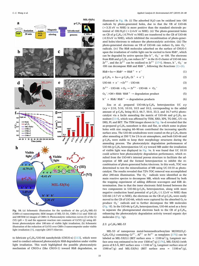
Fig. 10. (a) Schematic illustration for the synthesis of the g-C3N4/MIL-53(CMFe-x) nanocomposite; SEM images of MIL-53 (b), CMFe-3 (c) and TEM (d)and HRTEM (e) images of CMFe-3; Photocatalytic reduction curves (f) of the Cr(VI) (pH=3) and the apparent reaction rate constants of Cr(VI) (g) using dif-ferent photocatalysts after 180min of visible light irradiation; (h) Schematicillustration of the reduction of Cr(VI) over CMFe-3 nanocomposite under visiblelight irradiation [9], copyright (2017) Elsevier.
C.-C. Wang et al. Applied Catalysis B: Environmental 247 (2019) 24–48
33
respectively. MIL-53(Fe/Cr/Al) were widely used in the fields of ad-sorption [177–184], catalysis [185], separation [186,187], sensor[188] and photocatalysis [189–193].
Zhang et al. developed a facile solvothermal method (Fig. 10a) tofabricate g-C3N4/MIL-53(Fe) (CMFe-x, x is the weight content of g-C3N4
in the composite), which was confirmed by XRD, FTIR, SEM, TEM,HRTEM and BET [9]. The SEM and TEM images (Fig. 10b–e) demon-strated that g-C3N4 with various shapes were coated on the MIL-53(Fe)polyhedrons. Especially, the HRTEM revealed that the fringe spacing of0.336 nm was assigned to (002) crystal planes of g-C3N4. It could beobserved that g-C3N4 was successfully embedded onto the surface ofMIL-53(Fe) to produce heterojunction structure, which could be ex-pected to improve the transfer efficiency of photogenerated electrons.As displayed in Fig. 10f and g, the photocatalytic activities of CMFe-xtoward Cr(VI) reduction into Cr(III) under visible-light illuminationwere evaluated. The results revealed that CMFe-3 displayed best pho-tocatalytic Cr(VI) reduction performance with reaction rate of 0.0191(3.4 and 4.8 times higher than that of individual MIL-53(Fe) and g-
C3N4). As illustrated in Fig. 10h, the e− from the CB of g-C3N4 wastransferred to the CB of MIL-53(Fe), moreover, the h+ from the VB ofMIL-53(Fe) was moved to the VB of g-C3N4, which can reduce thecharge recombination and collect more free electrons in the CB of MIL-53(Fe). The involved reactions were listed as Eqs. (7)–(10).
g-C3N4 + hυ→ h+ (g-C3N4) + e− (g-C3N4) (7)
MIL-53 (Fe) + hυ→h+ (MIL-53 (Fe)) + e− (MIL-53 (Fe)) (8)
e− (g-C3N4) → e− (MIL-53 (Fe)) (9)
Cr2O72− + 14H+ + 6e- → 2Cr3+ + 7H2O (10)
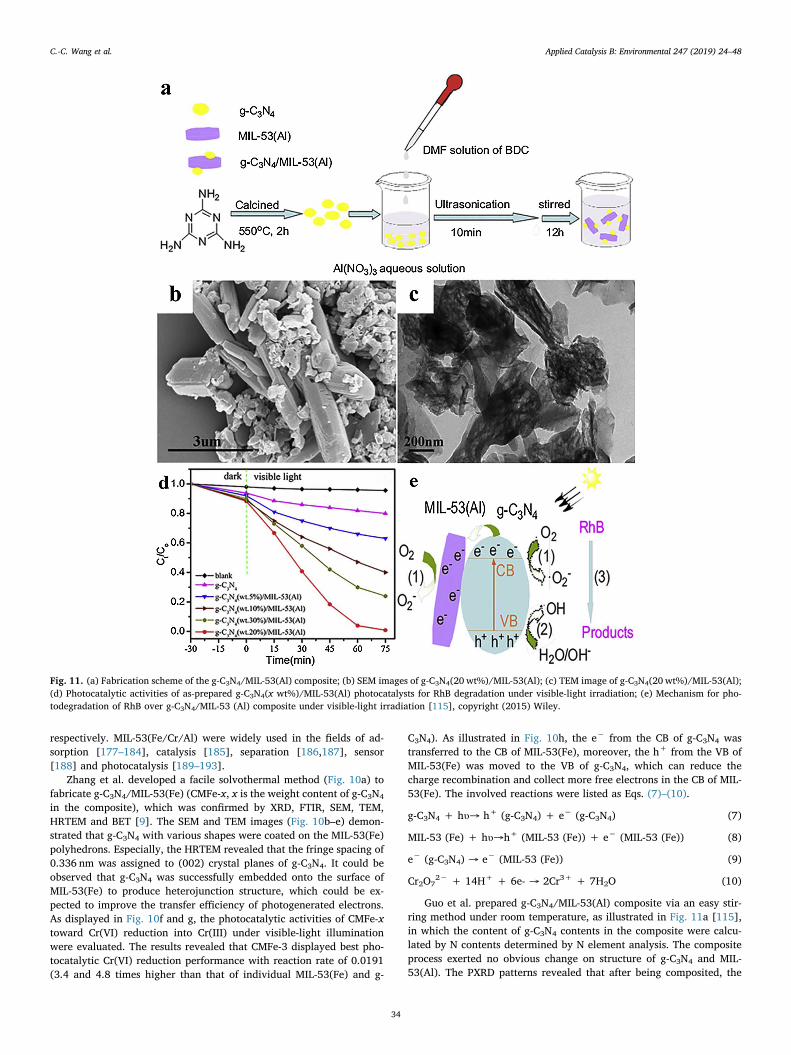
Guo et al. prepared g-C3N4/MIL-53(Al) composite via an easy stir-ring method under room temperature, as illustrated in Fig. 11a [115],in which the content of g-C3N4 contents in the composite were calcu-lated by N contents determined by N element analysis. The compositeprocess exerted no obvious change on structure of g-C3N4 and MIL-53(Al). The PXRD patterns revealed that after being composited, the
Fig. 11. (a) Fabrication scheme of the g-C3N4/MIL-53(Al) composite; (b) SEM images of g-C3N4(20 wt%)/MIL-53(Al); (c) TEM image of g-C3N4(20 wt%)/MIL-53(Al);(d) Photocatalytic activities of as-prepared g-C3N4(x wt%)/MIL-53(Al) photocatalysts for RhB degradation under visible-light irradiation; (e) Mechanism for pho-todegradation of RhB over g-C3N4/MIL-53 (Al) composite under visible-light irradiation [115], copyright (2015) Wiley.
C.-C. Wang et al. Applied Catalysis B: Environmental 247 (2019) 24–48
34
characteristic peak positions of g-C3N4 and MIL-53(Al) maintained well,however, the intensity g-C3N4/MIL-53(Al) composites decreased sig-nificantly due to their low crystallinity and minor crystal particles. Theminor size of MIL-53(Al) particles was confirmed by both SEM andTEM, in which the aggregation of MIL-53(Al) particles significantlydecreased with the aid of g-C3N4 (Fig. 11b and c). The UV–vis DRSdetermination exhibited that g-C3N4 (20 wt%)/MIL-53(Al) absorptionedge was calculated at 540 nm with band gap energy of ca. 2.64 eV,implying that g-C3N4 was incorporated into the lattice of MIL-53(Al).Also, the PL spectrum revealed that the PL emission intensity of the g-C3N4 (20 wt%)/MIL-53(Al) was weaker than that of pristine MIL-53(Al)and g-C3N4, indicating that the introduction of g-C3N4 resulted in de-clined recombination of photogenerated electrons and holes. As a re-sult, the optimal g-C3N4 (20 wt%)/MIL-53(Al) composite can achievenearly 100% RhB decomposition under visible light within 75min(Fig. 11d), in which ·O2
− played a major role to degrade RhB alongwith the h+ and ·OH as minor active species (Fig. 11e).
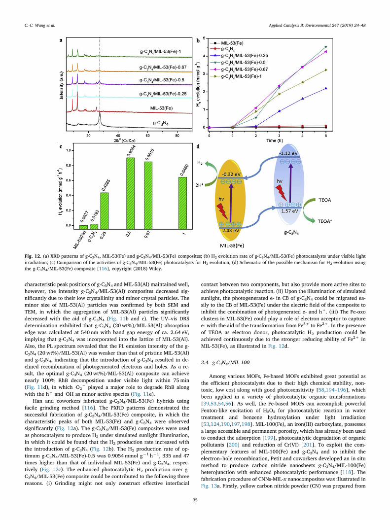
Han and coworkers fabricated g-C3N4/MIL-53(Fe) hybrids usingfacile grinding method [116]. The PXRD patterns demonstrated thesuccessful fabrication of g-C3N4/MIL-53(Fe) composite, in which thecharacteristic peaks of both MIL-53(Fe) and g-C3N4 were observedsignificantly (Fig. 12a). The g-C3N4/MIL-53(Fe) composites were usedas photocatalysts to produce H2 under simulated sunlight illumination,in which it could be found that the H2 production rate increased withthe introduction of g-C3N4 (Fig. 12b). The H2 production rate of op-timum g-C3N4/MIL-53(Fe)-0.5 was 0.9054mmol g−1 h−1, 335 and 47times higher than that of individual MIL-53(Fe) and g-C3N4, respec-tively (Fig. 12c). The enhanced photocatalytic H2 production over g-C3N4/MIL-53(Fe) composite could be contributed to the following threereasons. (i) Grinding might not only construct effective interfacial
contact between two components, but also provide more active sites toachieve photocatalytic reaction. (ii) Upon the illumination of simulatedsunlight, the photogenerated e- in CB of g-C3N4 could be migrated ea-sily to the CB of MIL-53(Fe) under the electric field of the composite toinhibit the combination of photogenerated e- and h+. (iii) The Fe-oxoclusters in MIL-53(Fe) could play a role of electron acceptor to capturee- with the aid of the transformation from Fe3+ to Fe2+. In the presenceof TEOA as electron donor, photocatalytic H2 production could beachieved continuously due to the stronger reducing ability of Fe2+ inMIL-53(Fe), as illustrated in Fig. 12d.
2.4. g-C3N4/MIL-100
Among various MOFs, Fe-based MOFs exhibited great potential asthe efficient photocatalysts due to their high chemical stability, non-toxic, low cost along with good photosensitivity [58,194–196], whichbeen applied in a variety of photocatalytic organic transformations[39,53,54,56]. As well, the Fe-based MOFs can accomplish powerfulFenton-like excitation of H2O2 for photocatalytic reaction in watertreatment and benzene hydroxylation under light irradiation[53,124,190,197,198]. MIL-100(Fe), an iron(III) carboxylate, possessesa large accessible and permanent porosity, which has already been usedto conduct the adsorption [199], photocatalytic degradation of organicpollutants [200] and reduction of Cr(VI) [201]. To exploit the com-plementary features of MIL-100(Fe) and g-C3N4 and to inhibit theelectron–hole recombination, Petit and coworkers developed an in situmethod to produce carbon nitride nanosheets g-C3N4/MIL-100(Fe)heterojunction with enhanced photocatalytic performance [118]. Thefabrication procedure of CNNs-MIL-x nanocomposites was illustrated inFig. 13a. Firstly, yellow carbon nitride powder (CN) was prepared from
Fig. 12. (a) XRD patterns of g-C3N4, MIL-53(Fe) and g-C3N4/MIL-53(Fe) composites; (b) H2 evolution rate of g-C3N4/MIL-53(Fe) photocatalysts under visible lightirradiation; (c) Comparison of the activities of g-C3N4/MIL-53(Fe) photocatalysts for H2 evolution; (d) Schematic of the possible mechanism for H2 evolution usingthe g-C3N4/MIL-53(Fe) composite [116], copyright (2018) Wiley.
C.-C. Wang et al. Applied Catalysis B: Environmental 247 (2019) 24–48
35
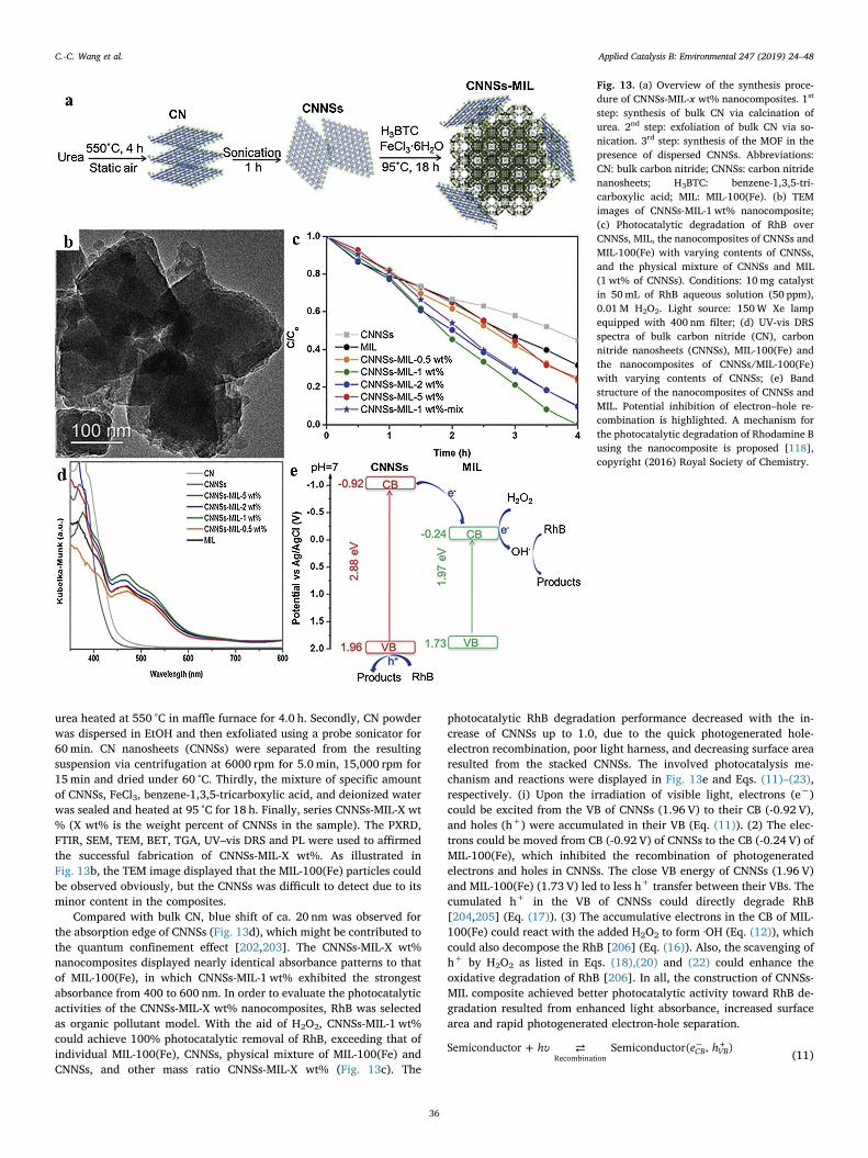
urea heated at 550 °C in maffle furnace for 4.0 h. Secondly, CN powderwas dispersed in EtOH and then exfoliated using a probe sonicator for60min. CN nanosheets (CNNSs) were separated from the resultingsuspension via centrifugation at 6000 rpm for 5.0 min, 15,000 rpm for15min and dried under 60 °C. Thirdly, the mixture of specific amountof CNNSs, FeCl3, benzene-1,3,5-tricarboxylic acid, and deionized waterwas sealed and heated at 95 °C for 18 h. Finally, series CNNSs-MIL-X wt% (X wt% is the weight percent of CNNSs in the sample). The PXRD,FTIR, SEM, TEM, BET, TGA, UV–vis DRS and PL were used to affirmedthe successful fabrication of CNNSs-MIL-X wt%. As illustrated inFig. 13b, the TEM image displayed that the MIL-100(Fe) particles couldbe observed obviously, but the CNNSs was difficult to detect due to itsminor content in the composites.
Compared with bulk CN, blue shift of ca. 20 nm was observed forthe absorption edge of CNNSs (Fig. 13d), which might be contributed tothe quantum confinement effect [202,203]. The CNNSs-MIL-X wt%nanocomposites displayed nearly identical absorbance patterns to thatof MIL-100(Fe), in which CNNSs-MIL-1 wt% exhibited the strongestabsorbance from 400 to 600 nm. In order to evaluate the photocatalyticactivities of the CNNSs-MIL-X wt% nanocomposites, RhB was selectedas organic pollutant model. With the aid of H2O2, CNNSs-MIL-1 wt%could achieve 100% photocatalytic removal of RhB, exceeding that ofindividual MIL-100(Fe), CNNSs, physical mixture of MIL-100(Fe) andCNNSs, and other mass ratio CNNSs-MIL-X wt% (Fig. 13c). The
photocatalytic RhB degradation performance decreased with the in-crease of CNNSs up to 1.0, due to the quick photogenerated hole-electron recombination, poor light harness, and decreasing surface arearesulted from the stacked CNNSs. The involved photocatalysis me-chanism and reactions were displayed in Fig. 13e and Eqs. (11)–(23),respectively. (i) Upon the irradiation of visible light, electrons (e−)could be excited from the VB of CNNSs (1.96 V) to their CB (-0.92 V),and holes (h+) were accumulated in their VB (Eq. (11)). (2) The elec-trons could be moved from CB (-0.92 V) of CNNSs to the CB (-0.24 V) ofMIL-100(Fe), which inhibited the recombination of photogeneratedelectrons and holes in CNNSs. The close VB energy of CNNSs (1.96 V)and MIL-100(Fe) (1.73 V) led to less h+ transfer between their VBs. Thecumulated h+ in the VB of CNNSs could directly degrade RhB[204,205] (Eq. (17)). (3) The accumulative electrons in the CB of MIL-100(Fe) could react with the added H2O2 to form ·OH (Eq. (12)), whichcould also decompose the RhB [206] (Eq. (16)). Also, the scavenging ofh+ by H2O2 as listed in Eqs. (18),(20) and (22) could enhance theoxidative degradation of RhB [206]. In all, the construction of CNNSs-MIL composite achieved better photocatalytic activity toward RhB de-gradation resulted from enhanced light absorbance, increased surfacearea and rapid photogenerated electron-hole separation.
+ ⇄− +hυ e hSemiconductor Semiconductor( , )CB VB
Recombination (11)
Fig. 13. (a) Overview of the synthesis proce-dure of CNNSs-MIL-x wt% nanocomposites. 1st
step: synthesis of bulk CN via calcination ofurea. 2nd step: exfoliation of bulk CN via so-nication. 3rd step: synthesis of the MOF in thepresence of dispersed CNNSs. Abbreviations:CN: bulk carbon nitride; CNNSs: carbon nitridenanosheets; H3BTC: benzene-1,3,5-tri-carboxylic acid; MIL: MIL-100(Fe). (b) TEMimages of CNNSs-MIL-1 wt% nanocomposite;(c) Photocatalytic degradation of RhB overCNNSs, MIL, the nanocomposites of CNNSs andMIL-100(Fe) with varying contents of CNNSs,and the physical mixture of CNNSs and MIL(1 wt% of CNNSs). Conditions: 10mg catalystin 50mL of RhB aqueous solution (50 ppm),0.01M H2O2. Light source: 150W Xe lampequipped with 400 nm filter; (d) UV-vis DRSspectra of bulk carbon nitride (CN), carbonnitride nanosheets (CNNSs), MIL-100(Fe) andthe nanocomposites of CNNSs/MIL-100(Fe)with varying contents of CNNSs; (e) Bandstructure of the nanocomposites of CNNSs andMIL. Potential inhibition of electron–hole re-combination is highlighted. A mechanism forthe photocatalytic degradation of Rhodamine Busing the nanocomposite is proposed [118],copyright (2016) Royal Society of Chemistry.
C.-C. Wang et al. Applied Catalysis B: Environmental 247 (2019) 24–48
36
H2O2 + H+ + e− ⇄ H2O+OH· (12)
= +E@298K: (SHE)/V 0.9881–0.0591pH 0.0591log(H O )
–0.0591log(HO )H O /HO 2 2
·
2 2.
(13)
+ + ⇄+ −OH H e H O·2 (14)
= +E@298K: (SHE)/V 2.5384–0.0591 pH 0.0591 log(HO )HO H O/··
2 (15)
+ →vRhB OH ProductsOH·· (16)
+ →+
+v hRhB Productsh VBVB (17)
+ ⇄ ++ +HO hH H O VB2·
2 2 (18)
= +⋅E SHE HO@298K: ( )/ V 1.4359–0.0591 pH 0.0591log( )
- 0.0591 log(H O )
HO /H O 2·
2 2
2 2 2
(19)
+ ⇄ ++ +HO hO H VB2 2· (20)
=
+
HO
P
@298K: E (SHE)/V -0.0460–0.0591 pH - 0.0591 log( )
0.0591 log
O HO
O
/ 2·
2 2·
2 (21)
+ ⇄ ++ +hO 2H H O 2 VB2 2 2 (22)
= +E P
H O
@298K: (SHE)/V 0.6949–0.0591 pH 0.0296 log
- 0.0296 log( )O H O O/
2 2
2 2 2 2
(23)
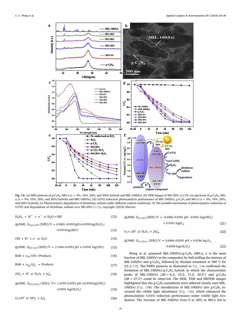
Wang et al. prepared MIL-100(Fe)/g-C3N4 (MG-x, x is the massfraction of MIL-100(Fe) in the composite) by ball-milling the mixture ofMIL-100(Fe) and g-C3N4, followed by thermal treatment at 300 °C for2 h [119]. The PXRD patterns as illustrated in Fig. 14a confirmed theformation of MIL-100(Fe)/g-C3N4 hybrid, in which the characteristicpeaks of MIL-100(Fe) (2θ=6.2, 10.2, 11.0, 20.0°) and g-C3N4
(2θ=27.2°) could be observed. The SEM, TEM and HRTEM imageshighlighted that the g-C3N4 nanosheets were adhered closely onto MIL-100(Fe) (Fig. 14b). The introduction of MIL-100(Fe) into g-C3N4 in-creased the visible light absorbance (Fig. 14c), which enhanced thephotocatalytic Cr(VI) reduction performance under visible light irra-diation. The increase of MIL-100(Fe) from 0 to 20% in MG-x led to
Fig. 14. (a) XRD patterns of g-C3N4, MG-x (x=5%, 10%, 20%, and 30%) hybrids and MIL-100(Fe); (b) TEM images of MG-20%; (c) UV–vis spectrum of g-C3N4, MG-x (x=5%, 10%, 20%, and 30%) hybrids and MIL-100(Fe); (d) Cr(VI) reduction photocatalytic performance of MIL-100(Fe), g-C3N4 and MG-x (x=5%, 10%, 20%,and 30%) hybrids; (e) Photocatalytic degradation of diclofenac sodium under different control conditions; (f) The possible mechanism of photocatalytic reduction ofCr(VI) and degradation of diclofenac sodium over MG-20% [119], copyright (2018) Elsevier.
C.-C. Wang et al. Applied Catalysis B: Environmental 247 (2019) 24–48
37
increasing Cr(VI) reduction performance due to both improved visible-light harness and the rapid charge transfer at the heterojunctions(Fig. 14d). Excessive MIL-100(Fe) resulted into declined unfavorablecharge transfer at the interface of heterojunctions [107]. Taking MG-20% as example, the photogenerated electrons in the CB of g-C3N4
(-1.12 V) were transferred to the CB of MIL-100(Fe) (-0.11 V), whichfacilitated the transformation from Cr(VI) to Cr(III) (Fig. 14f). Underthis situation, if the holes produced in the VB of g-C3N4 (1.84 V) and
MIL-100(Fe) (2.52 V) were consumed by some scavengers like citricacid, oxalic acid and diclofenac sodium, the separation of electrons andholes could be accelerated to achieve efficient Cr(VI) reduction(Fig. 14e).
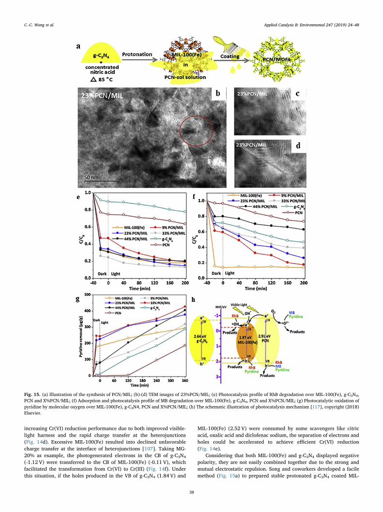
Considering that both MIL-100(Fe) and g-C3N4 displayed negativepolarity, they are not easily combined together due to the strong andmutual electrostatic repulsion. Song and coworkers developed a facilemethod (Fig. 15a) to prepared stable protonated g-C3N4 coated MIL-
Fig. 15. (a) Illustration of the synthesis of PCN/MIL; (b)-(d) TEM images of 23%PCN/MIL; (e) Photocatalysis profile of RhB degradation over MIL-100(Fe), g-C3N4,PCN and X%PCN/MIL; (f) Adsorption and photocatalysis profile of MB degradation over MIL-100(Fe), g-C3N4, PCN and X%PCN/MIL; (g) Photocatalytic oxidation ofpyridine by molecular oxygen over MIL-100(Fe), g-C3N4, PCN and X%PCN/MIL; (h) The schematic illustration of photocatalysis mechanism [117], copyright (2018)Elsevier.
C.-C. Wang et al. Applied Catalysis B: Environmental 247 (2019) 24–48
38
100(Fe) (PCN/MIL) [117], in which the protonated g-C3N4 (PCN) wasprepared via stirring the mixture of g-C3N4 powder and concentratedHNO3 under 85 °C for several hours. Taking 23%PCN/MIL as example,its HRTEM images illustrated that the overlapping morphology wasformed between MIL-100(Fe) channels and ultrathin PCN sheets(Fig. 15b–d). In this work, the successful PCN coating on MIL-100(Fe)was further confirmed by contact angle measurement. For example,23%PCN/MIL displayed highly hydrophilic behavior with a contactangle of 0°, which was identical to MIL-100(Fe), while quite differentfrom g-C3N4 (135.6°), PCN (26°), mechanically mixed g-C3N4+MIL-100(Fe) (18.9°) and mechanically mixed PCN+MIL-100(Fe) (24.2°).The organic dyes (like RhB and MB) and pyridine were selected to in-vestigate the photocatalytic degradation performance of as-preparedPCN/MIL-100(Fe). The pristine MIL-100(Fe) displayed different ad-sorption activities toward RhB (1.56× 1.35× 0.42 nm) and MB(1.38×0.64×0.21 nm) [29] due to that the adsorption process wasoccurred on the outer surface and in the pores of MIL-100(Fe) [207]. Asto the removal performance toward RhB, 33%PCN/MIL exhibitedhighest photocatalytic decomposition (86.9%) with the aid of bothadsorption and photocatalysis (Fig. 15e), in which holes were the mostactive specie to degrade RhB (Fig. 15h). While, 9%PCN/MIL accom-plished the optimal photocatalytic activity toward MB resulted from thehighly dispersed active species existing over the ultrathin PCN film, inwhich both superoxide radicals and holes along with hydroxyl radicalsare responsible to the MB degradation (Fig. 15f). As to the oxidativedenitrogenation of pyridine, 33%PCN/MIL can achieved 400 μg g−1
denitrogenation efficiency within 360min (Fig. 15g), in which the su-peroxide radicals and holes played primary roles as highlighted inFig. 15h. In all, the introduction of protonated g-C3N4 could help MIL-100(Fe) regulate its framework structure, surface property along withpore size. As well, the combination of MIL-100(Fe) provided g-C3N4 anideal platform to achieve uniform distribution of active sites, which canhelp inhibit the electron-hole recombination. Additionally, the higherporosity and surface area felicitated the larger adsorption densities ofthe targeted pollutants, which could also favor the enhanced photo-catalytic performance of PCN/MIL.
3. The current status of g-C3N4/MOF/X ternary photocatalysts
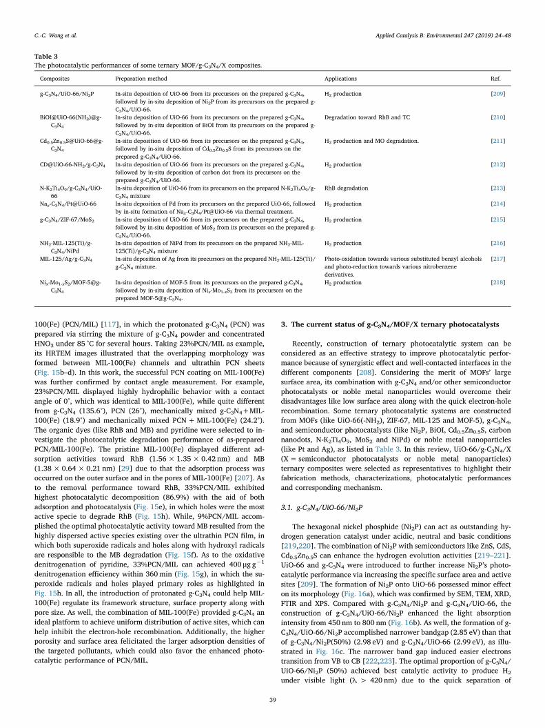
Recently, construction of ternary photocatalytic system can beconsidered as an effective strategy to improve photocatalytic perfor-mance because of synergistic effect and well-contacted interfaces in thedifferent components [208]. Considering the merit of MOFs’ largesurface area, its combination with g-C3N4 and/or other semiconductorphotocatalysts or noble metal nanoparticles would overcome theirdisadvantages like low surface area along with the quick electron-holerecombination. Some ternary photocatalytic systems are constructedfrom MOFs (like UiO-66(-NH2), ZIF-67, MIL-125 and MOF-5), g-C3N4,and semiconductor photocatalysts (like Ni2P, BiOI, Cd0.5Zn0.5S, carbonnanodots, N-K2Ti4O9, MoS2 and NiPd) or noble metal nanoparticles(like Pt and Ag), as listed in Table 3. In this review, UiO-66/g-C3N4/X(X= semiconductor photocatalysts or noble metal nanoparticles)ternary composites were selected as representatives to highlight theirfabrication methods, characterizations, photocatalytic performancesand corresponding mechanism.
3.1. g-C3N4/UiO-66/Ni2P
The hexagonal nickel phosphide (Ni2P) can act as outstanding hy-drogen generation catalyst under acidic, neutral and basic conditions[219,220]. The combination of Ni2P with semiconductors like ZnS, CdS,Cd0.5Zn0.5S can enhance the hydrogen evolution activities [219–221].UiO-66 and g-C3N4 were introduced to further increase Ni2P’s photo-catalytic performance via increasing the specific surface area and activesites [209]. The formation of Ni2P onto UiO-66 possessed minor effecton its morphology (Fig. 16a), which was confirmed by SEM, TEM, XRD,FTIR and XPS. Compared with g-C3N4/Ni2P and g-C3N4/UiO-66, theconstruction of g-C3N4/UiO-66/Ni2P enhanced the light absorptionintensity from 450 nm to 800 nm (Fig. 16b). As well, the formation of g-C3N4/UiO-66/Ni2P accomplished narrower bandgap (2.85 eV) than thatof g-C3N4/Ni2P(50%) (2.98 eV) and g-C3N4/UiO-66 (2.99 eV), as illu-strated in Fig. 16c. The narrower band gap induced easier electronstransition from VB to CB [222,223]. The optimal proportion of g-C3N4/UiO-66/Ni2P (50%) achieved best catalytic activity to produce H2
under visible light (λ > 420 nm) due to the quick separation of
Table 3The photocatalytic performances of some ternary MOF/g-C3N4/X composites.
Composites Preparation method Applications Ref.
g-C3N4/UiO-66/Ni2P In-situ deposition of UiO-66 from its precursors on the prepared g‐C3N4,followed by in-situ deposition of Ni2P from its precursors on the prepared g-C3N4/UiO-66.
H2 production [209]
BiOI@UiO-66(NH2)@g-C3N4
In-situ deposition of UiO-66 from its precursors on the prepared g‐C3N4,followed by in-situ deposition of BiOI from its precursors on the prepared g-C3N4/UiO-66.
Degradation toward RhB and TC [210]
Cd0.5Zn0.5S@UiO-66@g-C3N4
In-situ deposition of UiO-66 from its precursors on the prepared g‐C3N4,followed by in-situ deposition of Cd0.5Zn0.5S from its precursors on theprepared g-C3N4/UiO-66.
H2 production and MO degradation. [211]
CD@UiO-66-NH2/g-C3N4 In-situ deposition of UiO-66 from its precursors on the prepared g‐C3N4,followed by in-situ deposition of carbon dot from its precursors on theprepared g-C3N4/UiO-66.
H2 production [212]
N-K2Ti4O9/g-C3N4/UiO-66
In-situ deposition of UiO-66 from its precursors on the prepared N-K2Ti4O9/g-C3N4 mixture
RhB degradation [213]
Nax-C3N4/Pt@UiO-66 In-situ deposition of Pd from its precursors on the prepared UiO-66, followedby in-situ formation of Nax-C3N4/Pt@UiO-66 via thermal treatment.
H2 production [214]
g-C3N4/ZIF-67/MoS2 In-situ deposition of UiO-66 from its precursors on the prepared g‐C3N4,followed by in-situ deposition of MoS2 from its precursors on the prepared g-C3N4/UiO-66.
H2 production [215]
NH2-MIL-125(Ti)/g-C3N4/NiPd
In-situ deposition of NiPd from its precursors on the prepared NH2-MIL-125(Ti)/g-C3N4 mixture
H2 production [216]
MIL-125/Ag/g-C3N4 In-situ deposition of Ag from its precursors on the prepared NH2-MIL-125(Ti)/g-C3N4 mixture.
Photo-oxidation towards various substituted benzyl alcoholsand photo-reduction towards various nitrobenzenederivatives.
[217]
Nix-Mo1-xS2/MOF-5@g-C3N4
In-situ deposition of MOF-5 from its precursors on the prepared g‐C3N4,followed by in-situ deposition of Nix-Mo1-xS2 from its precursors on theprepared MOF-5@g-C3N4.
H2 production [218]
C.-C. Wang et al. Applied Catalysis B: Environmental 247 (2019) 24–48
39
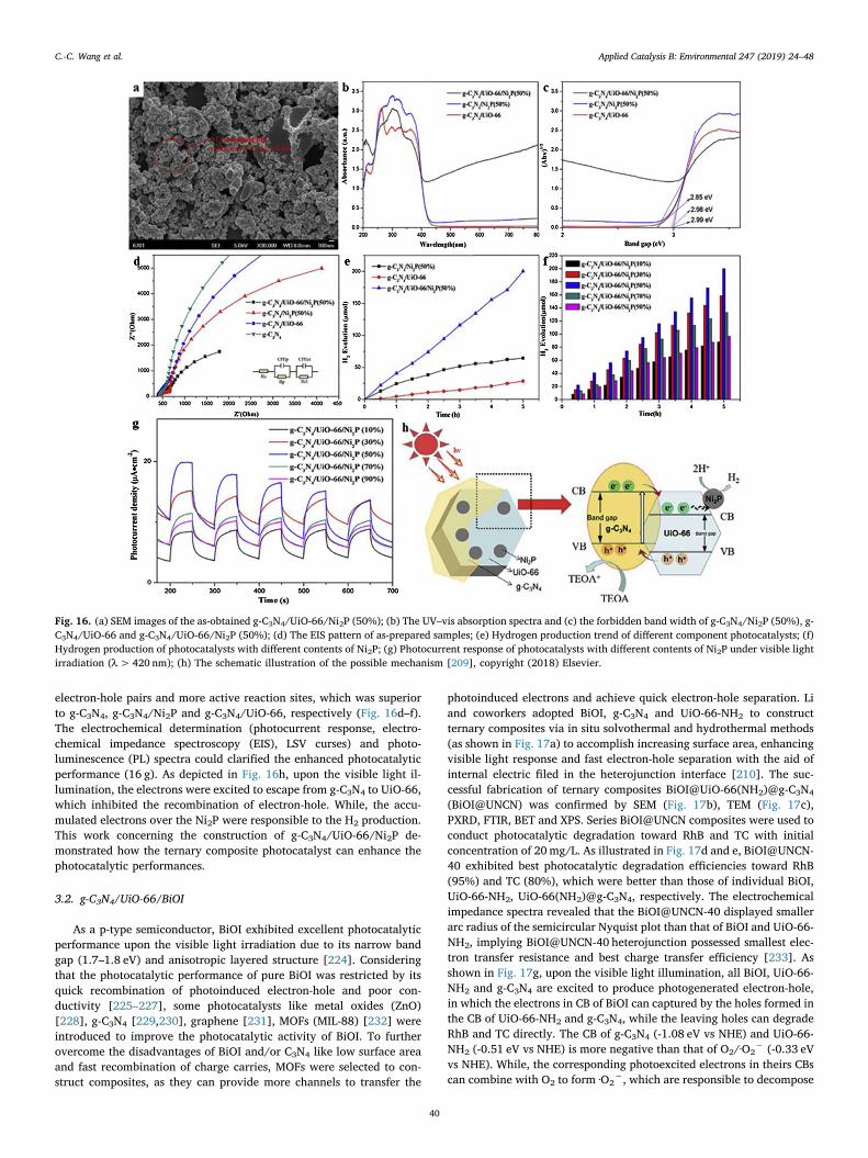
electron-hole pairs and more active reaction sites, which was superiorto g-C3N4, g-C3N4/Ni2P and g-C3N4/UiO-66, respectively (Fig. 16d–f).The electrochemical determination (photocurrent response, electro-chemical impedance spectroscopy (EIS), LSV curses) and photo-luminescence (PL) spectra could clarified the enhanced photocatalyticperformance (16 g). As depicted in Fig. 16h, upon the visible light il-lumination, the electrons were excited to escape from g-C3N4 to UiO-66,which inhibited the recombination of electron-hole. While, the accu-mulated electrons over the Ni2P were responsible to the H2 production.This work concerning the construction of g-C3N4/UiO-66/Ni2P de-monstrated how the ternary composite photocatalyst can enhance thephotocatalytic performances.
3.2. g-C3N4/UiO-66/BiOI
As a p-type semiconductor, BiOI exhibited excellent photocatalyticperformance upon the visible light irradiation due to its narrow bandgap (1.7–1.8 eV) and anisotropic layered structure [224]. Consideringthat the photocatalytic performance of pure BiOI was restricted by itsquick recombination of photoinduced electron-hole and poor con-ductivity [225–227], some photocatalysts like metal oxides (ZnO)[228], g-C3N4 [229,230], graphene [231], MOFs (MIL-88) [232] wereintroduced to improve the photocatalytic activity of BiOI. To furtherovercome the disadvantages of BiOI and/or C3N4 like low surface areaand fast recombination of charge carries, MOFs were selected to con-struct composites, as they can provide more channels to transfer the
photoinduced electrons and achieve quick electron-hole separation. Liand coworkers adopted BiOI, g-C3N4 and UiO-66-NH2 to constructternary composites via in situ solvothermal and hydrothermal methods(as shown in Fig. 17a) to accomplish increasing surface area, enhancingvisible light response and fast electron-hole separation with the aid ofinternal electric filed in the heterojunction interface [210]. The suc-cessful fabrication of ternary composites BiOI@UiO-66(NH2)@g-C3N4
(BiOI@UNCN) was confirmed by SEM (Fig. 17b), TEM (Fig. 17c),PXRD, FTIR, BET and XPS. Series BiOI@UNCN composites were used toconduct photocatalytic degradation toward RhB and TC with initialconcentration of 20mg/L. As illustrated in Fig. 17d and e, BiOI@UNCN-40 exhibited best photocatalytic degradation efficiencies toward RhB(95%) and TC (80%), which were better than those of individual BiOI,UiO-66-NH2, UiO-66(NH2)@g-C3N4, respectively. The electrochemicalimpedance spectra revealed that the BiOI@UNCN-40 displayed smallerarc radius of the semicircular Nyquist plot than that of BiOI and UiO-66-NH2, implying BiOI@UNCN-40 heterojunction possessed smallest elec-tron transfer resistance and best charge transfer efficiency [233]. Asshown in Fig. 17g, upon the visible light illumination, all BiOI, UiO-66-NH2 and g-C3N4 are excited to produce photogenerated electron-hole,in which the electrons in CB of BiOI can captured by the holes formed inthe CB of UiO-66-NH2 and g-C3N4, while the leaving holes can degradeRhB and TC directly. The CB of g-C3N4 (-1.08 eV vs NHE) and UiO-66-NH2 (-0.51 eV vs NHE) is more negative than that of O2/·O2
− (-0.33 eVvs NHE). While, the corresponding photoexcited electrons in theirs CBscan combine with O2 to form ·O2
−, which are responsible to decompose
Fig. 16. (a) SEM images of the as-obtained g-C3N4/UiO-66/Ni2P (50%); (b) The UV–vis absorption spectra and (c) the forbidden band width of g-C3N4/Ni2P (50%), g-C3N4/UiO-66 and g-C3N4/UiO-66/Ni2P (50%); (d) The EIS pattern of as-prepared samples; (e) Hydrogen production trend of different component photocatalysts; (f)Hydrogen production of photocatalysts with different contents of Ni2P; (g) Photocurrent response of photocatalysts with different contents of Ni2P under visible lightirradiation (λ>420 nm); (h) The schematic illustration of the possible mechanism [209], copyright (2018) Elsevier.
C.-C. Wang et al. Applied Catalysis B: Environmental 247 (2019) 24–48
40
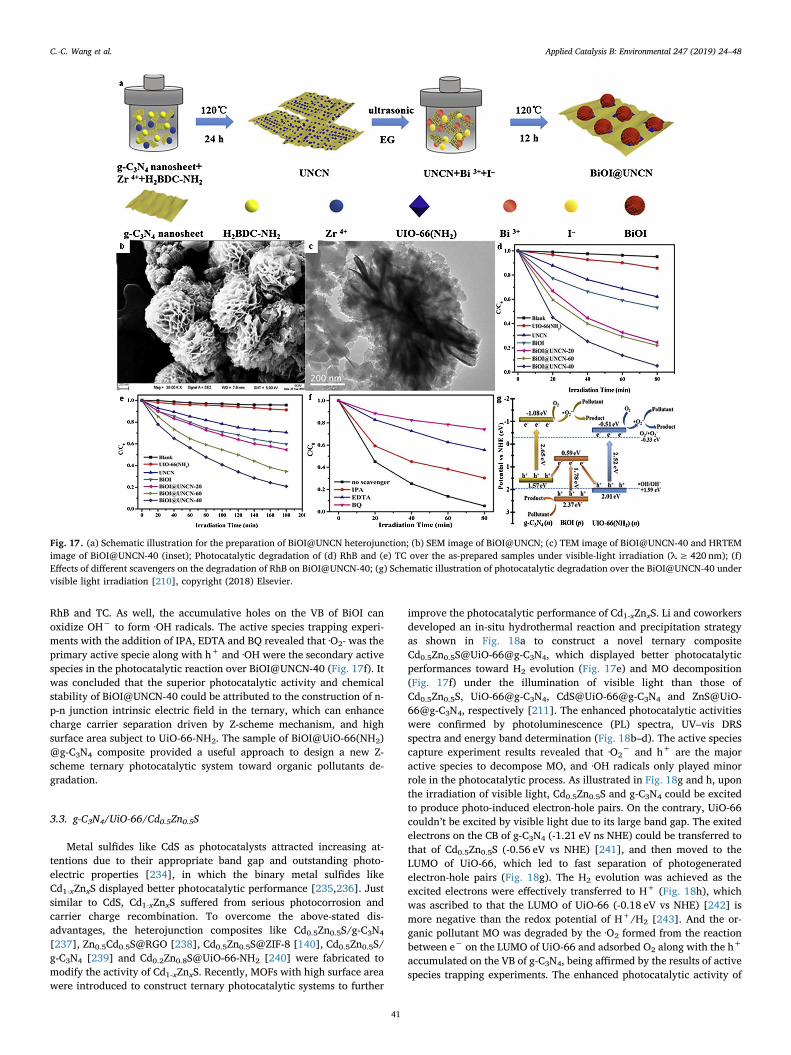
RhB and TC. As well, the accumulative holes on the VB of BiOI canoxidize OH− to form ·OH radicals. The active species trapping experi-ments with the addition of IPA, EDTA and BQ revealed that ·O2- was theprimary active specie along with h+ and ·OH were the secondary activespecies in the photocatalytic reaction over BiOI@UNCN-40 (Fig. 17f). Itwas concluded that the superior photocatalytic activity and chemicalstability of BiOI@UNCN-40 could be attributed to the construction of n-p-n junction intrinsic electric field in the ternary, which can enhancecharge carrier separation driven by Z-scheme mechanism, and highsurface area subject to UiO-66-NH2. The sample of BiOI@UiO-66(NH2)@g-C3N4 composite provided a useful approach to design a new Z-scheme ternary photocatalytic system toward organic pollutants de-gradation.
3.3. g-C3N4/UiO-66/Cd0.5Zn0.5S
Metal sulfides like CdS as photocatalysts attracted increasing at-tentions due to their appropriate band gap and outstanding photo-electric properties [234], in which the binary metal sulfides likeCd1-xZnxS displayed better photocatalytic performance [235,236]. Justsimilar to CdS, Cd1-xZnxS suffered from serious photocorrosion andcarrier charge recombination. To overcome the above-stated dis-advantages, the heterojunction composites like Cd0.5Zn0.5S/g-C3N4
[237], Zn0.5Cd0.5S@RGO [238], Cd0.5Zn0.5S@ZIF-8 [140], Cd0.5Zn0.5S/g-C3N4 [239] and Cd0.2Zn0.8S@UiO-66-NH2 [240] were fabricated tomodify the activity of Cd1-xZnxS. Recently, MOFs with high surface areawere introduced to construct ternary photocatalytic systems to further
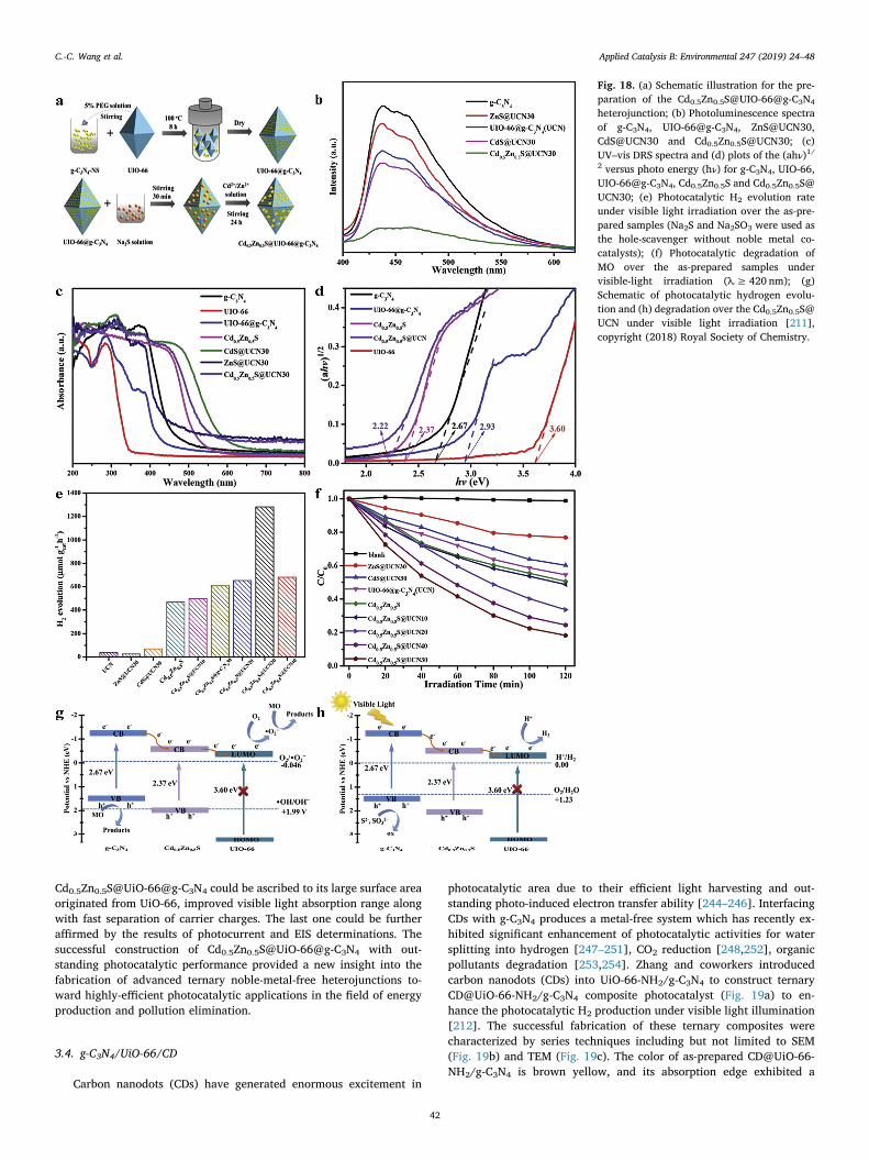
improve the photocatalytic performance of Cd1-xZnxS. Li and coworkersdeveloped an in-situ hydrothermal reaction and precipitation strategyas shown in Fig. 18a to construct a novel ternary compositeCd0.5Zn0.5S@UiO-66@g-C3N4, which displayed better photocatalyticperformances toward H2 evolution (Fig. 17e) and MO decomposition(Fig. 17f) under the illumination of visible light than those ofCd0.5Zn0.5S, UiO-66@g-C3N4, CdS@UiO-66@g-C3N4 and ZnS@UiO-66@g-C3N4, respectively [211]. The enhanced photocatalytic activitieswere confirmed by photoluminescence (PL) spectra, UV–vis DRSspectra and energy band determination (Fig. 18b–d). The active speciescapture experiment results revealed that ·O2
− and h+ are the majoractive species to decompose MO, and ·OH radicals only played minorrole in the photocatalytic process. As illustrated in Fig. 18g and h, uponthe irradiation of visible light, Cd0.5Zn0.5S and g-C3N4 could be excitedto produce photo-induced electron-hole pairs. On the contrary, UiO-66couldn’t be excited by visible light due to its large band gap. The exitedelectrons on the CB of g-C3N4 (-1.21 eV ns NHE) could be transferred tothat of Cd0.5Zn0.5S (-0.56 eV vs NHE) [241], and then moved to theLUMO of UiO-66, which led to fast separation of photogeneratedelectron-hole pairs (Fig. 18g). The H2 evolution was achieved as theexcited electrons were effectively transferred to H+ (Fig. 18h), whichwas ascribed to that the LUMO of UiO-66 (-0.18 eV vs NHE) [242] ismore negative than the redox potential of H+/H2 [243]. And the or-ganic pollutant MO was degraded by the ·O2 formed from the reactionbetween e− on the LUMO of UiO-66 and adsorbed O2 along with the h+
accumulated on the VB of g-C3N4, being affirmed by the results of activespecies trapping experiments. The enhanced photocatalytic activity of
Fig. 17. (a) Schematic illustration for the preparation of BiOI@UNCN heterojunction; (b) SEM image of BiOI@UNCN; (c) TEM image of BiOI@UNCN-40 and HRTEMimage of BiOI@UNCN-40 (inset); Photocatalytic degradation of (d) RhB and (e) TC over the as-prepared samples under visible-light irradiation (λ≥ 420 nm); (f)Effects of different scavengers on the degradation of RhB on BiOI@UNCN-40; (g) Schematic illustration of photocatalytic degradation over the BiOI@UNCN-40 undervisible light irradiation [210], copyright (2018) Elsevier.
C.-C. Wang et al. Applied Catalysis B: Environmental 247 (2019) 24–48
41
Cd0.5Zn0.5S@UiO-66@g-C3N4 could be ascribed to its large surface areaoriginated from UiO-66, improved visible light absorption range alongwith fast separation of carrier charges. The last one could be furtheraffirmed by the results of photocurrent and EIS determinations. Thesuccessful construction of Cd0.5Zn0.5S@UiO-66@g-C3N4 with out-standing photocatalytic performance provided a new insight into thefabrication of advanced ternary noble-metal-free heterojunctions to-ward highly-efficient photocatalytic applications in the field of energyproduction and pollution elimination.
3.4. g-C3N4/UiO-66/CD
Carbon nanodots (CDs) have generated enormous excitement in
photocatalytic area due to their efficient light harvesting and out-standing photo-induced electron transfer ability [244–246]. InterfacingCDs with g-C3N4 produces a metal-free system which has recently ex-hibited significant enhancement of photocatalytic activities for watersplitting into hydrogen [247–251], CO2 reduction [248,252], organicpollutants degradation [253,254]. Zhang and coworkers introducedcarbon nanodots (CDs) into UiO-66-NH2/g-C3N4 to construct ternaryCD@UiO-66-NH2/g-C3N4 composite photocatalyst (Fig. 19a) to en-hance the photocatalytic H2 production under visible light illumination[212]. The successful fabrication of these ternary composites werecharacterized by series techniques including but not limited to SEM(Fig. 19b) and TEM (Fig. 19c). The color of as-prepared CD@UiO-66-NH2/g-C3N4 is brown yellow, and its absorption edge exhibited a
Fig. 18. (a) Schematic illustration for the pre-paration of the Cd0.5Zn0.5S@UIO-66@g-C3N4
heterojunction; (b) Photoluminescence spectraof g-C3N4, UIO-66@g-C3N4, ZnS@UCN30,CdS@UCN30 and Cd0.5Zn0.5S@UCN30; (c)UV–vis DRS spectra and (d) plots of the (ahν)1/2 versus photo energy (hν) for g-C3N4, UIO-66,UIO-66@g-C3N4, Cd0.5Zn0.5S and Cd0.5Zn0.5S@UCN30; (e) Photocatalytic H2 evolution rateunder visible light irradiation over the as-pre-pared samples (Na2S and Na2SO3 were used asthe hole-scavenger without noble metal co-catalysts); (f) Photocatalytic degradation ofMO over the as-prepared samples undervisible-light irradiation (λ≥ 420 nm); (g)Schematic of photocatalytic hydrogen evolu-tion and (h) degradation over the Cd0.5Zn0.5S@UCN under visible light irradiation [211],copyright (2018) Royal Society of Chemistry.
C.-C. Wang et al. Applied Catalysis B: Environmental 247 (2019) 24–48
42
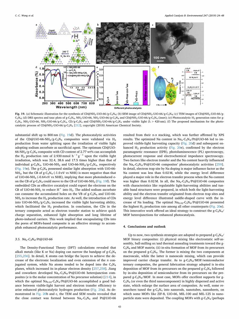
substantial shift up to 800 nm (Fig. 19d). The photocatalytic activitiesof the CD@UiO-66-NH2/g-C3N4 composites were validated via H2
production from water splitting upon the irradiation of visible lightadopting sodium ascorbate as sacrificial agent. The optimum CD@UiO-66-NH2/g-C3N4 composite with CD content of 2.77 wt% can accomplishthe H2 production rate of 2.930mmol h−1 g−1 upon the visible lightirradiation, which was 32.4, 38.6 and 17.5 times higher than that ofindividual g-C3N4, UiO-66-NH2 and UiO-66-NH2/g-C3N4, respectively(Fig. 19e). The g-C3N4 possessed similar light absorption with UiO-66-NH2, but the CB of g-C3N4 (-1.0 eV vs NHE) is more negative than thatof UiO-66-NH2 (-0.64 eV vs NHE), implying that more photoinduced e-on the CB of g-C3N4 could move to the CB of UiO-66-NH2 (Fig. 19f). Theembedded CDs as effective cocatalyst could export the electrons on theCB of UiO-66-NH2 to reduce H+ into H2. The added sodium ascorbatecan consume the accumulated holes on the VB of g-C3N4 and UiO-66-NH2 to increase the H2 production rate. As well, the introduction of CDsinto UiO-66-NH2/g-C3N4 increased the visible light harvesting ability,which facilitated the H2 production. In conclusion, the CDs in theternary composite acted as electron transfer station to achieve quickcharge separation, enhanced light absorption and long lifetime ofphoto-induced carriers. This work implied that encapsulating CDs intothe pores of MOFs-based composite is an effective strategy to accom-plish enhanced photocatalytic performance.
3.5. Nax-C3N4/Pt@UiO-66
The Density-Functional Theory (DFT) calculations revealed thatalkali metals (like K or Na) doping can narrow the bandgap of g-C3N4
[255,256]. In detail, K atoms can bridge the layers to achieve the de-crease of the electronic localization and even extension of the π con-jugated system, while Na atoms tended to be doped into the C3N4
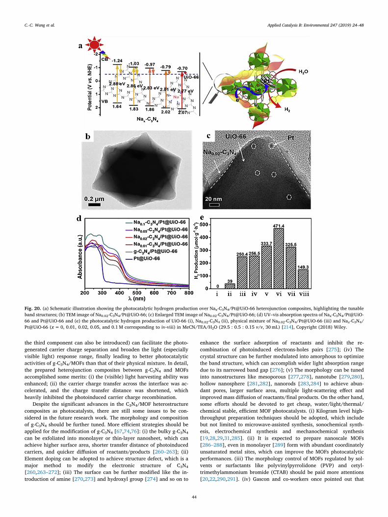
planes, which increased its in-planar electron density [257,258]. Jiangand coworkers developed Nax-C3N4/Pt@UiO-66 heterojunction com-posites (x is the molar concentration of Na precursor solution) [214], inwhich the optimal Na0.02-C3N4/Pt@UiO-66 accomplished a good bal-ance between visible-light harvest and electron transfer efficiency toarise enhanced photocatalytic hydrogen production (Fig. 20a). As de-monstrated in Fig. 20b and c, the TEM and SEM results revealed thatthe close contact was formed between Nax-C3N4 and Pt@UiO-66
resulted from their π-π stacking, which was further affirmed by XPSresults. The optimized Na content in Nax-C3N4/Pt@UiO-66 led to im-proved visible-light harvesting capacity (Fig. 20d) and subsequent en-hanced H2 production activity (Fig. 20e), confirmed by the electronparamagnetic resonance (EPR), photoluminescence (PL) spectroscopy,photocurrent response and electrochemical impedance spectroscopy.Two factors like electron transfer and the Na content heavily influencedthe Nax-C3N4/Pt@UiO-66 composites’ photocatalytic activities [259].In detail, electron trap site by Na doping is major influence factor as theNa content was less than 0.02M, while the energy level differenceplayed a major role in the electron transfer process when the Na contentwas higher than 0.02M. In all, the Nax-C3N4/Pt@UiO-66 compositeswith characteristics like regulatable light-harvesting abilities and tun-able band structures were prepared, in which both the light-harvestingability and the electron transfer originated from electron trap sites andenergy level difference illustrated saddle-shaped curve with the in-crease of Na loading. The optimal Na0.02-C3N4/Pt@UiO-66 presentedthe highest H2 production rate among all other counterparts (Fig. 20e).This innovative work offered an ideal strategy to construct the g-C3N4/MOF heterojunctions for enhanced photocatalysis.
4. Conclusions and outlook
Up to now, two synthesis strategies are adopted to prepared g-C3N4/MOF binary composites: (i) physical mixing like electrostatic self-as-sembly, ball-milling or/and thermal annealing treatments toward the g-C3N4 and MOF matrix; (ii) in-situ formation of MOF from its precursorson the prepared g-C3N4. The former is mixing the two components atmacroscale, while the latter is nanoscale mixing, which can provideimproved carrier charge transfer. As to g-C3N4/MOF/semiconductorternary composites, the general fabrication strategy adopted is in-situdeposition of MOF from its precursors on the prepared g‐C3N4 followedby in-situ deposition of semiconductor from its precursors on the pre-pared g-C3N4/MOF. In most case, MOFs offer excellent supports for g-C3N4 (or even the third nanocomponent) in highly dispersed and activestate, which enlarge the surface area of composites. As well, some re-searchers tuned the g-C3N4 into nanorods, nanotubes, nanosheets, onwhich some MOFs like ZIF-8, UiO-66, MIL-100 and MIL-125 in nano-particle state were deposited. The coupling MOFs with g-C3N4 (perhaps
Fig. 19. (a) Schematic illustration for the synthesis of CD@NH2-UiO-66/g-C3N4; (b) SEM image of CD@NH2-UiO-66/g-C3N4; (c) TEM images of CD@NH2-UiO-66/g-C3N4; (d) DRS spectra and tauc plots of g-C3N4, NH2-UiO-66, NH2-UiO-66/g-C3N4 and CD@NH2-UiO-66/g-C3N4 (inset); (e) Photocatalytic H2 generation rates for g-C3N4, NH2-UiO-66, NH2-UiO-66/g-C3N4, CD/g-C3N4 and CD@NH2-UiO-66/g-C3N4 under visible light (λ>420 nm); (f) The proposed mechanism for the photo-catalytic process of CD@NH2-UiO-66/g-C3N4 [212], copyright (2018) American Chemical Society.
C.-C. Wang et al. Applied Catalysis B: Environmental 247 (2019) 24–48
43
the third component can also be introduced) can facilitate the photo-generated carrier charge separation and broaden the light (especiallyvisible light) response range, finally leading to better photocatalyticactivities of g-C3N4/MOFs than that of their physical mixture. In detail,the prepared heterojunction composites between g-C3N4 and MOFsaccomplished some merits: (i) the (visible) light harvesting ability wasenhanced; (ii) the carrier charge transfer across the interface was ac-celerated, and the charge transfer distance was shortened, whichheavily inhibited the photoinduced carrier charge recombination.
Despite the significant advances in the C3N4/MOF heterostructurecomposites as photocatalysts, there are still some issues to be con-sidered in the future research work. The morphology and compositionof g-C3N4 should be further tuned. More efficient strategies should beapplied for the modification of g-C3N4 [67,74,76]: (i) the bulky g-C3N4
can be exfoliated into monolayer or thin-layer nanosheet, which canachieve higher surface area, shorter transfer distance of photoinducedcarriers, and quicker diffusion of reactants/products [260–263]; (ii)Element doping can be adopted to achieve structure defect, which is amajor method to modify the electronic structure of C3N4
[260,263–272]; (iii) The surface can be further modified like the in-troduction of amine [270,273] and hydroxyl group [274] and so on to
enhance the surface adsorption of reactants and inhibit the re-combination of photoinduced electrons-holes pairs [275]; (iv) Thecrystal structure can be further modulated into amorphous to optimizethe band structure, which can accomplish wider light absorption rangedue to its narrowed band gap [276]; (v) The morphology can be tunedinto nanostructures like mesoporous [277,278], nanotube [279,280],hollow nanosphere [281,282], nanorods [283,284] to achieve abun-dant pores, larger surface area, multiple light-scattering effect andimproved mass diffusion of reactants/final products. On the other hand,some efforts should be devoted to get cheap, water/light/thermal/chemical stable, efficient MOF photocatalysts. (i) Kilogram level high-throughput preparation techniques should be adopted, which includebut not limited to microwave-assisted synthesis, sonochemical synth-esis, electrochemical synthesis and mechanochemical synthesis[19,28,29,31,285]. (ii) It is expected to prepare nanoscale MOFs[286–288], even in monolayer [289] form with abundant coordinatelyunsaturated metal sites, which can improve the MOFs photocatalyticperformances. (iii) The morphology control of MOFs regulated by sol-vents or surfactants like polyvinylpyrrolidone (PVP) and cetyl-trimethylammonium bromide (CTAB) should be paid more attentions[20,22,290,291]. (iv) Gascon and co-workers once pointed out that
Fig. 20. (a) Schematic illustration showing the photocatalytic hydrogen production over Nax-C3N4/Pt@UiO-66 heterojunction composites, highlighting the tunableband structures; (b) TEM image of Na0.02-C3N4/Pt@UiO-66; (c) Enlarged TEM image of Na0.02-C3N4/Pt@UiO-66; (d) UV–vis absorption spectra of Nax-C3N4/Pt@UiO-66 and Pt@UiO-66 and (e) the photocatalytic hydrogen production of UiO-66 (i), Na0.02-C3N4 (ii), physical mixture of Na0.02-C3N4/Pt@UiO-66 (iii) and Nax-C3N4/Pt@UiO-66 (x=0, 0.01, 0.02, 0.05, and 0.1M corresponding to iv-viii) in MeCN/TEA/H2O (29.5 : 0.5 : 0.15 v/v, 30mL) [214], Copyright (2018) Wiley.
C.-C. Wang et al. Applied Catalysis B: Environmental 247 (2019) 24–48
44
semiconducting behavior (CB-VB) only occurs in a very limited subsetof MOFs, and HOMO-LUMO gap terminology should be utilized to de-scribe the photocatalytic behaviors in the most MOFs as molecularcatalysts [29,292,293]. In the future work, more efforts should be put toidentify whether some specific MOFs should be labeled as semi-conductor or molecular photocatalysts.
As to the application of g-C3N4/MOF composites, further worksshould be conducted in future. (i) Some theoretical calculations likedensity functional theory (DFT) were adopted to affirm the structure-property relationship; (ii) The influence factors affecting the photo-catalytic activities should be investigated. When g-C3N4/MOF compo-sites were used to conduct water environment remediation, the factorslike pollutant concentration, co-existing ions (salinity) and dissolvedorganic matters (DOM) should be considered. Also, the photocatalyticremoval performances g-C3N4/MOF composites toward pollutants (likeCr(VI) and organic pollutants) in real wastewater under real sunlightirradiation should be evaluated. Especially, more organic pollutantsmodels like Pharmaceutical and Personal Care Products (PPCPs) andperfluorinated organic compounds (PFCs) should be selected to test theg-C3N4/MOF composites’ photocatalytic degradation efficiencies, inwhich the TOC removal percentage (degree of materialization) not onlymaximum absorbance of specific organic pollutant was suggested todetermined. Up to now, few reported cases dealt with the pathway oforganic decomposition with g-C3N4/MOF composites as photocatalysts.In the future, mass spectra are suggested to determine the intermediateproducts and final products to clarify the degradation pathway.
Considering that both pristine g-C3N4 and MOFs are star photo-catalysts in the field of H2 evolution via water splitting, CO2 reduction,Cr(VI) reduction and organic pollutants degradation, their compositeswill achieve enhanced photocatalytic performances via combining oftheir merits and overcoming their disadvantages. It was expected thatthe current synthesis methods, photocatalytic performances, me-chanism and even challenges for g-C3N4/MOFs composites highlightedin this review can provide new insight in the exploration and utilizationof these composites. In all, we believe that the present studies providestimuli to carry out intensive research in g-C3N4/MOFs compositephotocatalysts, and open a new perspective for the sustainable devel-opment with the aid of these emerging photocatalytic systems.
Acknowledgements
This work was supported by the National Natural ScienceFoundation of China (51578034, 51878023), Great Wall ScholarsTraining Program Project of Beijing Municipality Universities (CIT&TCD20180323), the Project of Construction of Innovation Teams andTeacher Career Development for Universities and Colleges underBeijing Municipality (IDHT20170508), the Beijing Talent Project(2018A35), and Beijing Advanced Innovation Center for Future UrbanDesign (No. UDC2016030200).
References
[1] L. Jeongyong, O.K. Farha, R. John, K.A. Scheidt, S.B.T. Nguyen, J.T. Hupp, Chem.Soc. Rev 38 (2009) 1450–1459.
[2] P. García-García, M. Müller, A. Corma, Chem. Sci. 5 (2014) 2979–3007.[3] C.J. Doonan, C.J. Sumby, CrystEngComm 19 (2017) 4044–4048.[4] O.K. Farha, A.Ö. Yazaydın, I. Eryazici, C.D. Malliakas, B.G. Hauser,
M.G. Kanatzidis, S.T. Nguyen, R.Q. Snurr, J.T. Hupp, Nat. Chem. 2 (2010)944–948.
[5] H.-C.J. Zhou, S. Kitagawa, Chem. Soc. Rev 43 (2014) 5415–5418.[6] H. Lan, L. Li, X. An, F. Liu, C. Chen, H. Liu, J. Qu, Appl. Catal. B: Environ. 204
(2017) 49–57.[7] J.-R. Li, R.J. Kuppler, H.-C. Zhou, Chem. Soc. Rev 38 (2009) 1477–1504.[8] T. Rodenas, I. Luz, G. Prieto, B. Seoane, H. Miro, A. Corma, F. Kapteijn,
F.X. Llabrés i Xamena, J. Gascon, Nat. Mater. 14 (2014) 48–55.[9] W. Huang, N. Liu, X. Zhang, M. Wu, L. Tang, Appl. Surf. Sci. 425 (2017) 107–116.
[10] X.-Y. Xu, C. Chu, H. Fu, X.-D. Du, P. Wang, W. Zheng, C.-C. Wang, Chem. Eng. J.350 (2018) 436–444.
[11] A. Liu, C.-C. Wang, C.-z. Wang, H.-f. Fu, W. Peng, Y.-L. Cao, H.-Y. Chu, A.-F. Du, J.Colloid Interface Sci. 512 (2018) 730–739.
[12] X.-D. Du, C.-C. Wang, J.-G. Liu, X.-D. Zhao, J. Zhong, Y.-X. Li, J. Li, P. Wang, J.Colloid Interface Sci. 506 (2017) 437–441.
[13] J.-J. Li, C.-C. Wang, H.-f. Fu, J.-R. Cui, P. Xu, J. Guo, J.-R. Li, Dalton Trans. 46(2017) 10197–10201.
[14] D. Sheng, L. Zhu, C. Xu, C. Xiao, Y. Wang, Y. Wang, L. Chen, J. Diwu, J. Chen,Z. Chai, T.E. Albrecht-Schmitt, S. Wang, Environ. Sci. Technol. 51 (2017)3471–3479.
[15] X. Zhao, Y. Wei, H. Zhao, Z. Gao, Y. Zhang, L. Zhi, Y. Wang, H. Huang, J. ColloidInterface Sci. 514 (2018) 234–239.
[16] Y. Peng, Y. Zhang, H. Huang, C. Zhong, Chem. Eng. J. 333 (2018) 678–685.[17] L. Liang, L. Liu, F. Jiang, C. Liu, D. Yuan, Q. Chen, D. Wu, H.-L. Jiang, M. Hong,
Inorg. Chem. 57 (2018) 4891–4897.[18] Q. Yang, B. Wang, Y. Chen, Y. Xie, J. Li, Chin. Chem. Lett. 30 (2019) 234–238.[19] C.C. Wang, Y.S. Ho, Scientometrics 109 (2016) 481–513.[20] H. Fu, Z. Wang, X. Wang, P. Wang, C.-C. Wang, CrystEngComm 20 (2018)
1473–1477.[21] X.-D. Du, W. Zheng, X.-H. Yi, J.-P. Zhao, P. Wang, C.-C. Wang, CrystEngComm 20
(2018) 2608–2616.[22] H. Fu, X. Wang, P. Wang, Z. Wang, H. Ren, C.-C. Wang, Dalton Trans. 47 (2018)
9014–9020.[23] A. Liu, C.-Z. Wang, C. Chu, H.-Y. Chu, X. Chen, A.-F. Du, J. Mao, W. Zheng, C.-
C. Wang, J. Environ. Chem. Eng. 6 (2018) 4961–4969.[24] X. Yang, J. Qin, Y. Jiang, R. Li, Y. Li, H. Tang, RSC Adv. 4 (2014) 18627–18636.[25] D. Ma, B. Li, Z. Shi, Chin. Chem. Lett. 29 (2018) 827–830.[26] X.-Y. Ren, L.-H. Lu, Chin. Chem. Lett. 26 (2015) 1439–1445.[27] J. Li, Y. Wang, Y. Yu, Q. Li, Chin. Chem. Lett. 29 (2018) 837–841.[28] C.-C. Wang, X.-D. Du, J. Li, X.-X. Guo, P. Wang, J. Zhang, Appl. Catal. B: Environ.
193 (2016) 198–216.[29] C.-C. Wang, J.-R. Li, X.-L. Lv, Y.-Q. Zhang, G. Guo, Energy Environ. Sci. 7 (2014)
2831–2867.[30] H.-P. Jing, C.-C. Wang, Y.-W. Zhang, P. Wang, R. Li, Rsc Adv. 4 (2014)
54454–54462.[31] C.-C. Wang, Y.-Q. Zhang, J. Li, P. Wang, J. Mol. Struct. 1083 (2015) 127–136.[32] X.-H. Yi, F.-X. Wang, X.-D. Du, H. Fu, C.-C. Wang, Polyhedron 152 (2018)
216–224.[33] L. Zhu, D. Sheng, C. Xu, X. Dai, M.A. Silver, J. Li, P. Li, Y. Wang, Y. Wang, L. Chen,
C. Xiao, J. Chen, R. Zhou, C. Zhang, O.K. Farha, Z. Chai, T.E. Albrecht-Schmitt,S. Wang, J. Am. Chem. Soc. 139 (2017) 14873–14876.
[34] X. Fang, Q. Shang, Y. Wang, L. Jiao, T. Yao, Y. Li, Q. Zhang, Y. Luo, H.-L. Jiang,Adv. Mater. 30 (2018) 1705112.
[35] C. Xu, K. Sun, Y.-X. Zhou, X. Ma, H.-L. Jiang, Chem. Commun. 54 (2018)2498–2501.
[36] D. Li, S.-H. Yu, H.-L. Jiang, Adv. Mater. 30 (2018) 1707377.[37] Z. Han, W. Shi, P. Cheng, Chin. Chem. Lett. 29 (2018) 819–822.[38] A. Dhakshinamoorthy, Z. Li, H. Garcia, Chem. Soc. Rev 47 (2018) 8134–8172.[39] D. Wang, J. Albero, H. García, Z. Li, J. Catal. 349 (2017) 156–162.[40] L. Zeng, X. Guo, C. He, C. Duan, ACS Catal. 6 (2016) 7935–7947.[41] Y. Chen, D. Wang, X. Deng, Z. Li, Catal. Sci. Technol. 7 (2017) 4893–4904.[42] X. Deng, M. Hao, Z. Li, Curr. Org. Chem. 22 (2018) 1825–1835.[43] F.X.L.I. Xamena, A. Corma, H. Garcia, J. Phys. Chem. C 111 (2007) 80–85.[44] Y. Li, H. Xu, S. Ouyang, J. Ye, Phys. Chem. Chem. Phys. 18 (2016) 7563–7572.[45] J.-L. Wang, C. Wang, W. Lin, ACS Catal. 2 (2012) 2630–2640.[46] X. Liang, L. Chen, L. Zhang, C.Y. Su, S.O. Chemistry, S.Y.-S. University, Chin. Sci.
Bull. 63 (2018) 248–265.[47] A. Mercedes, C. Esther, F. Belén, F.X. Xamena, I. Llabrés, G. Hermenegildo,
Chemistry 13 (2010) 5106–5112.[48] S. Wang, X. Wang, Small 11 (2015) 3097–3112.[49] T. Zhang, W. Lin, Struct. Bond. 157 (2013) 89–104.[50] S. Yuan, J.-S. Qin, H.-Q. Xu, J. Su, D. Rossi, Y. Chen, L. Zhang, C. Lollar, Q. Wang,
H.-L. Jiang, D.H. Son, H. Xu, Z. Huang, X. Zou, H.-C. Zhou, ACS Central Sci. 4(2018) 105–111.
[51] M. Ding, H.-L. Jiang, ACS Catal. 8 (2018) 3194–3201.[52] D. Sun, Y. Gao, J. Fu, X. Zeng, Z. Chen, Z. Li, Chem. Commun. 51 (2015)
2645–2648.[53] D. Wang, M. Wang, Z. Li, ACS Catal. 5 (2015) 6852–6857.[54] D. Wang, Z. Li, Catal. Sci. Technol. 5 (2015) 1623–1628.[55] D. Wang, Z. Li, J. Catal. 342 (2016) 151–157.[56] D. Wang, Y. Pan, L. Xu, Z. Li, J. Catal. 361 (2018) 248–254.[57] J.-D. Xiao, H.-L. Jiang, Acc. Chem. Res. (2018), https://doi.org/10.1021/acs.
accounts.1028b00521.[58] D. Wang, Z. Li, Res. Chem. Intermed. 43 (2017) 5169–5186.[59] Q. Xia, H. Wang, B. Huang, X. Yuan, J. Zhang, J. Zhang, L. Jiang, T. Xiong,
G. Zeng, Small (2018) 1803088.[60] S. Subhadeep, D. Gobinda, T. Jayshri, B. Rahul, J. Am. Chem. Soc. 136 (2014)
14845–14851.[61] G. Dong, Y. Zhang, Q. Pan, J. Qiu, J. Photochem. Photobiol. C 20 (2014) 33–50.[62] W. Ho, Z. Zhang, M. Xu, X. Zhang, X. Wang, Y. Huang, Appl. Catal. B: Environ. 179
(2015) 106–112.[63] F. Dong, L. Wu, Y. Sun, M. Fu, Z. Wu, S.C. Lee, J. Mater. Chem. 21 (2011)
15171–15174.[64] G. Mamba, A.K. Mishra, Appl. Catal. B: Environ. 198 (2016) 347–377.[65] Y. Cui, Z. Ding, P. Liu, M. Antonietti, X. Fu, X. Wang, Phys. Chem. Chem. Phys. 14
(2012) 1455–1462.[66] S. Cao, J. Yu, J. Phys. Chem. Lett. 5 (2014) 2101–2107.[67] J. Fu, J. Yu, C. Jiang, B. Cheng, Adv. Energy Mater. 8 (2018) 1701503.[68] W.-J. Ong, L.-L. Tan, Y.H. Ng, S.-T. Yong, S.-P. Chai, Chem. Rev. 116 (2016)
C.-C. Wang et al. Applied Catalysis B: Environmental 247 (2019) 24–48
45
7159–7329.[69] K.S. Lakhi, D.-H. Park, K. Al-Bahily, W. Cha, B. Viswanathan, J.-H. Choy, A. Vinu,
Chem. Soc. Rev 46 (2017) 72–101.[70] Y. Chen, Z. Zhan, J. Wang, Y. Shen, S. Liu, Y. Zhang, Chin. Chem. Lett. 29 (2018)
437–440.[71] B. Zhu, P. Xia, W. Ho, J. Yu, Appl. Surf. Sci. 344 (2015) 188–195.[72] M. Groenewolt, M. Antonietti, Adv. Mater. 17 (2005) 1789–1792.[73] H. Montigaud, B. Tanguy, G. Demazeau, I. Alves, S. Courjault, J. Mater. Sci. 35
(2000) 2547–2552.[74] J. Wen, J. Xie, X. Chen, X. Li, Appl. Surf. Sci. 391 (2017) 72–123.[75] S. Cao, J. Low, J. Yu, M. Jaroniec, Adv. Mater. 27 (2015) 2150–2176.[76] D. Masih, Y. Ma, S. Rohani, Appl. Catal. B: Environ. 206 (2017) 556–588.[77] S. Zhao, X. Zhao, S. Ouyang, Y. Zhu, Catal. Sci. Technol. 8 (2018) 1686–1695.[78] Y. Wang, X. Zhao, Y. Tian, Y. Wang, A.K. Jan, Y. Chen, Chem. Eur. J. 23 (2017)
419–426.[79] Y. Wang, J. Sun, J. Li, X. Zhao, Langmuir 33 (2017) 4694–4701.[80] J. Zhu, P. Xiao, H. Li, S.A.C. Carabineiro, ACS Appl. Mater. Interfaces 6 (2014)
16449–16465.[81] X.-H. Li, J.-S. Chen, X. Wang, J. Sun, M. Antonietti, J. Am. Chem. Soc. 133 (2011)
8074–8077.[82] D. Deng, K.S. Novoselov, Q. Fu, N. Zheng, Z. Tian, X. Bao, Nat. Nanotecchnol. 11
(2016) 218–230.[83] S. Ye, R. Wang, M.-Z. Wu, Y.-P. Yuan, Appl. Surf. Sci. 358 (2015) 15–27.[84] L. Ge, C. Han, Appl. Catal. B: Environ. 117-118 (2012) 268–274.[85] A. Pisanu, A. Speltini, B. Vigani, F. Ferrari, M. Mannini, N. Calisi, B. Cortigiani,
A. Caneschi, P. Quadrelli, A. Profumo, L. Malavasi, Dalton Trans. 47 (2018)6772–6778.
[86] C. Zhang, Y. Zhou, J. Bao, J. Fang, S. Zhao, Y. Zhang, X. Sheng, W. Chen, Chem.Eng. J. 346 (2018) 226–237.
[87] Y. He, Y. Wang, L. Zhang, B. Teng, M. Fan, Appl. Catal. B: Environ. 168-169(2015) 1–8.
[88] L. Ye, D. Wu, K.H. Chu, B. Wang, H. Xie, H.Y. Yip, P.K. Wong, Chem. Eng. J. 304(2016) 376–383.
[89] D. Xiao, K. Dai, Y. Qu, Y. Yin, H. Chen, Appl. Surf. Sci. 358 (2015) 181–187.[90] K. Wei, K. Li, Z. Zeng, Y. Dai, L. Yan, H. Guo, X. Luo, Chin. J. Catal. 38 (2017)
1804–1811.[91] X. Wang, Y. Liang, W. An, J. Hu, Y. Zhu, W. Cui, Appl. Catal. B: Environ. 219
(2017) 53–62.[92] Q. Sun, X. Hu, S. Zheng, J. Zhang, J. Sheng, Environ. Pollut. 245 (2019) 53–62.[93] A. Kumar, A. Kumar, G. Sharma, Aa.H. Al-Muhtaseb, M. Naushad, A.A. Ghfar,
C. Guo, F.J. Stadler, Chem. Eng. J. 339 (2018) 393–410.[94] Y. Wei, Q. Zou, P. Ye, M. Wang, X. Li, A. Xu, Chemosphere 208 (2018) 358–365.[95] S.C. Yan, Z.S. Li, Z.G. Zou, Langmuir 25 (2009) 10397–10401.[96] S. Vadivel, D. Maruthamani, A. Habibi-Yangjeh, B. Paul, S.S. Dhar, K. Selvam, J.
Colloid Interface Sci. 480 (2016) 126–136.[97] A. Naseri, M. Samadi, A. Pourjavadi, A.Z. Moshfegh, S. Ramakrishna, J. Mater.
Chem. A 5 (2017) 23406–23433.[98] N. Boonprakob, N. Wetchakun, S. Phanichphant, D. Waxler, P. Sherrell,
A. Nattestad, J. Chen, B. Inceesungvorn, J. Colloid Interface Sci. 417 (2014)402–409.
[99] L. Gu, J. Wang, Z. Zou, X. Han, J. Hazard. Mater. 268 (2014) 216–223.[100] Y.-F. Shen, C. Zhang, C.-G. Yan, H.-Q. Chen, Y.-J. Zhang, Chin. Chem. Lett. 28
(2017) 1312–1317.[101] H.-S. Zhai, L. Cao, X.-H. Xia, Chin. Chem. Lett. 24 (2013) 103–106.[102] L. Jiang, X. Yuan, Y. Pan, J. Liang, G. Zeng, Z. Wu, H. Wang, Appl. Catal. B:
Environ. 217 (2017) 388–406.[103] J. Li, B. Shen, Z. Hong, B. Lin, B. Gao, Y. Chen, Chem. Commun. 48 (2012)
12017–12019.[104] L. Shi, K. Chang, H. Zhang, X. Hai, L. Yang, T. Wang, J. Ye, Small 12 (2016)
4431–4439.[105] Z. Lin, X. Wang, Angew. Chem. Int. Ed. 125 (2013) 1779–1782.[106] W. Chen, T.-Y. Liu, T. Huang, X.-H. Liu, X.-J. Yang, Nanoscale 8 (2016)
3711–3719.[107] R. Wang, L. Gu, J. Zhou, X. Liu, F. Teng, C. Li, Y. Shen, Y. Yuan, Adv. Mater.
Interfaces 2 (2015) 1500037.[108] S. Li, W. Tao, H. Zhang, K. Chang, J. Ye, Adv. Funct. Mater. 25 (2015) 5360–5367.[109] S. Liu, F. Chen, S. Li, X. Peng, Y. Xiong, Appl. Catal. B: Environ. 211 (2017) 1–10.[110] L. Tian, X. Yang, Q. Liu, F. Qu, H. Tang, Appl. Surf. Sci. 455 (2018) 403–409.[111] S. Panneri, M. Thomas, P. Ganguly, B.N. Nair, A.P. Mohamed, K.G.K. Warrier,
U.S. Hareesh, Catal. Sci. Technol. 7 (2017) 2118–2128.[112] X. Liu, J. Zhang, Y. Dong, H. Li, Y. Xia, H. Wang, New J. Chem. 42 (2018)
12180–12187.[113] X. Zhang, Y. Yang, W. Huang, Y. Yang, Y. Wang, C. He, N. Liu, M. Wu, L. Tang,
Mater. Res. Bull. 99 (2018) 349–358.[114] Y. Zhang, J. Zhou, Q. Feng, X. Chen, Z. Hu, Chemosphere 212 (2018) 523–532.[115] D. Guo, R. Wen, M. Liu, H. Guo, J. Chen, W. Weng, Appl. Organomet. Chemi. 29
(2015) 690–697.[116] C. Bai, J. Bi, J. Wu, H. Meng, Y. Xu, Y. Han, X. Zhang, Appl. Organomet. Chemi.
(2018), https://doi.org/10.1002/aoc.4597.[117] J. Huang, X. Zhang, H. Song, C. Chen, F. Han, C. Wen, Appl. Surf. Sci. 441 (2018)
85–98.[118] J. Hong, C. Chen, F.E. Bedoya, G.H. Kelsall, D. O’Hare, C. Petit, Catal. Sci. Technol.
6 (2016) 5042–5051.[119] X.-D. Du, X.-H. Yi, P. Wang, J. Deng, C.-C. Wang, Chin. J. Catal. 40 (2019) 70–79.[120] B. Liu, Y. Wu, X. Han, J. Lv, J. Zhang, H. Shi, J. Mater. Sci.: Mater. Electron. 29
(2018) 17591–17601.
[121] Y. Gong, B. Yang, H. Zhang, X. Zhao, J. Mater. Chem. A 6 (2018) 23703–23711.[122] H. Wang, X. Yuan, Y. Wu, G. Zeng, X. Chen, L. Leng, H. Li, Appl. Catal. B: Environ.
174-175 (2015) 445–454.[123] D.A. Giannakoudakis, N.A. Travlou, J. Secor, T.J. Bandosz, Small 13 (2017)
201601758.[124] X. Li, Y. Pi, L. Wu, Q. Xia, J. Wu, Z. Li, J. Xiao, Appl. Catal. B: Environ. 202 (2017)
653–663.[125] Z.-D. Lei, Y.-C. Xue, W.-Q. Chen, L. Li, W.-H. Qiu, Y. Zhang, L. Tang, Small 14
(2018) 1802045.[126] X.-H. Yi, F.-X. Wang, X.-D. Du, P. Wang, C.-C. Wang, Appl. Organomet. Chemi. 32
(2018) e4621.[127] K.S. Park, Z. Ni, A.P. Côté, J.Y. Choi, R. Huang, F.J. Uribe-Romo, H.K. Chae,
M. O’Keeffe, O.M. Yaghi, Proc. Natl. Acad. Sci. 103 (2006) 10186–10191.[128] S. Gadipelli, W. Travis, W. Zhou, Z. Guo, Energy Environ. Sci. 7 (2014)
2232–2238.[129] C. Chen, J. Kim, D.A. Yang, W.S. Ahn, Chem. Eng. J. 168 (2011) 1134–1139.[130] G. Kumari, K. Jayaramulu, T.K. Maji, C. Narayana, J. Phys. Chem. A 117 (2013)
11006–11012.[131] Q. Song, S.K. Nataraj, M.V. Roussenova, J.C. Tan, D.J. Hughes, W. Li, P. Bourgoin,
M.A. Alam, A.K. Cheetham, S.A. Almuhtaseb, Energy Environ. Sci. 5 (2012)8359–8369.
[132] C. Hu, W. Xu, X. Mo, H. Li, S. Zhou, P. Zhang, K. Tang, Adsorption 24 (2018)733–744.
[133] U.P.N. Tran, K.K.A. Le, N.T.S. Phan, ACS Catal. 1 (2011) 120–127.[134] P.Z. Li, K. Aranishi, Q. Xu, Chem. Commun. 48 (2012) 3173–3175.[135] S. Liu, Z. Xiang, Z. Hu, X. Zheng, D. Cao, J. Mater. Chem. 21 (2011) 6649–6653.[136] Y. Zhang, S.-J. Park, Appl. Catal. B: Environ. 240 (2019) 92–101.[137] M. Zhang, Q. Shang, Y. Wan, Q. Cheng, G. Liao, Z. Pan, Appl. Catal. B: Environ.
241 (2019) 149–158.[138] G. Fan, X. Zheng, J. Luo, H. Peng, H. Lin, M. Bao, L. Hong, J. Zhou, Chem. Eng. J.
351 (2018) 782–790.[139] G. Fan, J. Luo, L. Guo, R. Lin, X. Zheng, S.A. Snyder, Chemosphere 209 (2018)
44–52.[140] J. Qiu, X.-F. Zhang, X. Zhang, Y. Feng, Y. Li, L. Yang, H. Lu, J. Yao, J. Hazard.
Mater. 349 (2018) 234–241.[141] X. Yang, Z. Wen, Z. Wu, X. Luo, Inorg. Chem. Front. 5 (2018) 687–693.[142] J. Gao, Y. Zhou, Z. Li, S. Yan, N. Wang, Z. Zou, Nanoscale 4 (2012) 3687–3692.[143] J. Cravillon, R. Nayuk, S. Springer, A. Feldhoff, K. Huber, M. Wiebcke, Chem.
Mater. 23 (2011) 2130–2141.[144] X. Wang, K. Maeda, A. Thomas, K. Takanabe, G. Xin, J.M. Carlsson, K. Domen,
M. Antonietti, Nat. Mater. 8 (2009) 76–80.[145] P. Xia, B. Zhu, J. Yu, S. Cao, M. Jaroniec, J. Mater. Chem. A 5 (2017) 3230–3238.[146] Y. Zheng, L. Lin, B. Wang, X. Wang, Angew. Chem. Int. Ed. 54 (2015)
12868–12884.[147] M. Marszewski, S. Cao, J. Yu, M. Jaroniec, Mater. Horiz. 2 (2015) 261–278.[148] X. Li, J. Wen, J. Low, Y. Fang, J. Yu, Sci. China Mater. 57 (2014) 70–100.[149] X. Wang, J. Liu, S. Leong, X. Lin, J. Wei, B. Kong, Y. Xu, Z.-X. Low, J. Yao,
H. Wang, ACS Appl. Mater. Interfaces 8 (2016) 9080–9087.[150] X. Zeng, L. Huang, C. Wang, J. Wang, J. Li, X. Luo, ACS Appl. Mater. Interfaces 8
(2016) 20274–20282.[151] M.E. Parolo, M.C. Savini, J.M. Vallés, M.T. Baschini, M.J. Avena, Appl. Clay Sci. 40
(2008) 179–186.[152] J.H. Cavka, S. Jakobsen, U. Olsbye, N. Guillou, C. Lamberti, S. Bordiga,
K.P. Lillerud, J. Am. Chem. Soc. 130 (2008) 13850–13851.[153] H. Wu, T. Yildirim, W. Zhou, J. Phys. Chem. Lett. 4 (2013) 925–930.[154] A.D. Wiersum, E. Soubeyrand-Lenoir, Q. Yang, B. Moulin, V. Guillerm, M.B. Yahia,
S. Bourrelly, A. Vimont, S. Miller, C. Vagner, M. Daturi, G. Clet, C. Serre,G. Maurin, P.L. Llewellyn, Chem. Asian J. 6 (2011) 3270–3280.
[155] L. Valenzano, B. Civalleri, S. Chavan, S. Bordiga, M.H. Nilsen, S. Jakobsen,K.P. Lillerud, C. Lamberti, Chem. Mater. 23 (2011) 1700–1718.
[156] W. Fu-Xue, W. Chong-Chen, W. Peng, X. Bi-Cong, Chin. J. Inorg. Chem. 33 (2017)713–737.
[157] S.-N. Kim, Y.-R. Lee, S.-H. Hong, M.-S. Jang, W.-S. Ahn, Catal. Today 245 (2015)54–60.
[158] F. Vermoortele, B. Bueken, Gl.Le Bars, B. Van de Voorde, M. Vandichel,K. Houthoofd, A. Vimont, M. Daturi, M. Waroquier, V. Van Speybroeck, J. Am.Chem. Soc. 135 (2013) 11465–11468.
[159] D. Sun, Y. Fu, W. Liu, L. Ye, D. Wang, L. Yang, X. Fu, Z. Li, Chem. Eur. J. 19 (2013)14279–14285.
[160] L. Shen, W. Wu, R. Liang, R. Lin, L. Wu, Nanoscale 5 (2013) 9374–9382.[161] C.G. Silva, I. Luz, F.X. Llabrés i Xamena, A. Corma, H. García, Chem.-Eur. J. 16
(2010) 11133–11138.[162] J. Long, S. Wang, Z. Ding, S. Wang, Y. Zhou, L. Huang, X. Wang, Chem. Commun.
48 (2012) 11656–11658.[163] L. Shen, S. Liang, W. Wu, R. Liang, L. Wu, J. Mater. Chem. A 1 (2013)
11473–11482.[164] D. Sun, Z. Li, Chin. J. Chem. 35 (2017) 135–147.[165] S. Chavan, J.G. Vitillo, D. Gianolio, O. Zavorotynska, B. Civalleri, S. Jakobsen,
M.H. Nilsen, L. Valenzano, C. Lamberti, K.P. Lillerud, S. Bordiga, Phys. Chem.Chem. Phys. 14 (2012) 1614–1626.
[166] H.R. Abid, H. Tian, H.-M. Ang, M.O. Tade, C.E. Buckley, S. Wang, Chem. Eng. J.187 (2012) 415–420.
[167] Q. Yang, V. Guillerm, F. Ragon, A.D. Wiersum, P.L. Llewellyn, C. Zhong, T. Devic,C. Serre, G. Maurin, Chem. Commun. 48 (2012) 9831–9833.
[168] N. Chang, X.-P. Yan, J. Chromatogr. A 1257 (2012) 116–124.[169] Y.-Y. Fu, C.-X. Yang, X.-P. Yan, Chem. Commun. 49 (2013) 7162–7164.
C.-C. Wang et al. Applied Catalysis B: Environmental 247 (2019) 24–48
46
[170] Y.S. Seo, N.A. Khan, S.H. Jhung, Chem. Eng. J. 270 (2015) 22–27.[171] Y. Horiuchi, T. Toyao, M. Saito, K. Mochizuki, M. Iwata, H. Higashimura, M. Anpo,
M. Matsuoka, J. Phys. Chem. C 116 (2012) 20848–20853.[172] M.A. Nasalevich, C.H. Hendon, J.G. Santaclara, K. Svane, B. van der Linden,
S.L. Veber, M.V. Fedin, A.J. Houtepen, M.A. van der Veen, F. Kapteijn, A. Walsh,J. Gascon, Sci. Rep. 6 (2016) 23676.
[173] A. Santiago Portillo, H.G. Baldoví, M.T. García Fernandez, S. Navalón, P. Atienzar,B. Ferrer, M. Alvaro, H. Garcia, Z. Li, J. Phys. Chem. C 121 (2017) 7015–7024.
[174] X. Xu, R. Liu, Y. Cui, X. Liang, C. Lei, S. Meng, Y. Ma, Z. Lei, Z. Yang, Appl. Catal. BEnviron. 210 (2017) 484–494.
[175] F. Millange, C. Serre, G. Férey, Chem. Commun. 8 (2002) 822–823.[176] G. Férey, M. Latroche, C. Serre, F. Millange, T. Loiseau, A. Percheron-Guégan,
Chem. Commun. 24 (2003) 2976–2977.[177] L. Hamon, C. Serre, T. Devic, T. Loiseau, F. Millange, G. Férey, G.D. Weireld, J.
Am. Chem. Soc. 131 (2009) 8775–8777.[178] P.L. Llewellyn, P. Horcajada, G. Maurin, T. Devic, N. Rosenbach, S. Bourrelly,
C. Serre, D. Vincent, S. Loera-Serna, Y. Filinchuk, G. Férey, J. Am. Chem. Soc. 131(2009) 13002–13008.
[179] G. de Combarieu, M. Morcrette, F. Millange, N. Guillou, J. Cabana, C.P. Grey,I. Margiolaki, G. Férey, J.M. Tarascon, Chem. Mater. 21 (2009) 1602–1611.
[180] F. Millange, N. Guillou, M.E. Medina, G. Férey, A. Carlin-Sinclair, K.M. Golden,R.I. Walton, Chem. Mater. 22 (2010) 4237–4245.
[181] X.-F. Chen, H. Zang, X. Wang, J.-G. Cheng, R.-S. Zhao, C.-G. Cheng, X.-Q. Lu,Analyst 137 (2012) 5411–5419.
[182] S. Bourrelly, B. Moulin, A. Rivera, G. Maurin, S. Devautour-Vinot, C. Serre,T. Devic, P. Horcajada, A. Vimont, G. Clet, M. Daturi, J.-C. Lavalley, S. Loera-Serna, R. Denoyel, P.L. Llewellyn, G. Férey, J. Am. Chem. Soc. 132 (2010)9488–9498.
[183] T.K. Trung, P. Trens, N. Tanchoux, S. Bourrelly, P.L. Llewellyn, S. Loera-Serna,C. Serre, T. Loiseau, F. Fajula, G. Férey, J. Am. Chem. Soc. 130 (2008)16926–16932.
[184] D.V. Patil, P.B.S. Rallapalli, G.P. Dangi, R.J. Tayade, R.S. Somani, H.C. Bajaj, Ind.Eng. Chem. Res. 50 (2011) 10516–10524.
[185] L. Ai, L. Li, C. Zhang, J. Fu, J. Jiang, Chem. Eur. J. 19 (2013) 15105–15108.[186] S. Couck, J.F. Denayer, G.V. Baron, T. Rémy, J. Gascon, F. Kapteijn, J. Am. Chem.
Soc. 131 (2009) 6326–6327.[187] V. Finsy, L. Ma, L. Alaerts, D. De Vos, G. Baron, J. Denayer, Microporous
Mesoporous Mater. 120 (2009) 221–227.[188] J. Jia, F. Xu, Z. Long, X. Hou, M.J. Sepaniak, Chem. Commun. 49 (2013)
4670–4672.[189] J.-J. Du, Y.-P. Yuan, J.-X. Sun, F.-M. Peng, X. Jiang, L.-G. Qiu, A.-J. Xie, Y.-H. Shen,
J.-F. Zhu, J. Hazard. Mater. 190 (2011) 945–951.[190] L. Ai, C. Zhang, L. Li, J. Jiang, Appl. Catal. B: Environ. 148-149 (2014) 191–200.[191] R. Liang, F. Jing, L. Shen, N. Qin, L. Wu, J. Hazard. Mater. 287 (2015) 364–372.[192] X. Feng, H. Chen, F. Jiang, J. Colloid Interface Sci. 494 (2017) 32–37.[193] Z. Jia, M. Jiang, G. Wu, Chem. Eng. J. 307 (2017) 283–290.[194] K.G.M. Laurier, F. Vermoortele, R. Ameloot, D.E. De Vos, J. Hofkens,
M.B.J. Roeffaers, J. Am. Chem. Soc. 135 (2013) 14488–14491.[195] D. Wang, R. Huang, W. Liu, D. Sun, Z. Li, ACS Catal. 4 (2014) 4254–4260.[196] L. Chi, Q. Xu, X. Liang, J. Wang, X. Su, Small 12 (2016) 1351–1358.[197] H. Lv, H. Zhao, T. Cao, L. Qian, Y. Wang, G. Zhao, J. Mol. Catal. A: Chem. 400
(2015) 81–89.[198] M. Cheng, C. Lai, Y. Liu, G. Zeng, D. Huang, C. Zhang, L. Qin, L. Hu, C. Zhou,
W. Xiong, Coord. Chem. Rev. 368 (2018) 80–92.[199] C. Petit, T.J. Bandosz, Adv. Funct. Mater. 21 (2011) 2108–2117.[200] C.-F. Zhang, L.-G. Qiu, F. Ke, Y.-J. Zhu, Y.-P. Yuan, G.-S. Xu, X. Jiang, J. Mate.
Chem. A 1 (2013) 14329–14334.[201] R. Liang, F. Jing, L. Shen, N. Qin, L. Wu, Nano Res. 8 (2015) 3237–3249.[202] P. Niu, L. Zhang, G. Liu, H.M. Cheng, Adv. Funct. Mater. 22 (2012) 4763–4770.[203] X. Zhang, X. Xie, H. Wang, J. Zhang, B. Pan, Y. Xie, J. Am. Chem. Soc. 135 (2013)
18–21.[204] F. Ke, L. Wang, J. Zhu, Nano Res. 8 (2015) 1834–1846.[205] N. Daneshvar, D. Salari, A.R. Khataee, J. Photochem. Photobiol., A 162 (2004)
317–322.[206] P. Pichat, C. Guillard, L. Amalric, A.C. Renard, O. Plaidy, Sol. Energy Mater. Sol.
Cells 38 (1995) 391–399.[207] J. Huang, H. Song, C. Chen, Y. Yang, N. Xu, X. Ji, C. Li, J.-A. You, J. Environ.
Chem. Eng. 5 (2017) 2579–2585.[208] F. Ning, M. Shao, S. Xu, Y. Fu, R. Zhang, M. Wei, D.G. Evans, X. Duan, Energy
Environ. Sci. 9 (2016) 2633–2643.[209] Z. Wang, Z. Jin, H. Yuan, G. Wang, B. Ma, J. Colloid Interface Sci. 532 (2018)
287–299.[210] Q. Liang, S. Cui, J. Jin, C. Liu, S. Xu, C. Yao, Z. Li, Appl. Surf. Sci. 456 (2018)
899–907.[211] Q. Liang, J. Jin, C. Liu, S. Xu, C. Yao, Z. Li, Inorg. Chem. Front. 5 (2018) 335–343.[212] X. Zhang, H. Dong, X.-J. Sun, D.-D. Yang, J.-L. Sheng, H.-L. Tang, X.-B. Meng, F.-
M. Zhang, ACS Sustain. Chem. Eng. 6 (2018) 11563–11569.[213] F. Wang, Y.T. Zhang, Y. Xu, X. Wang, S. Li, H. Yang, X. Liu, F. Wei, J. Environ.
Chem. Eng. 4 (2016) 3364–3373.[214] H.-L. Jiang, Y. Pan, D. Li, Chem. Eur. J. 24 (2018) 18403.[215] Z. Wang, Z. Jin, G. Wang, B. Ma, Int. J. Hydrogen Energy 43 (2018) 13039–13050.[216] J. Xu, J. Gao, C. Wang, Y. Yang, L. Wang, Appl. Catal. B: Environ. 219 (2017)
101–108.[217] Z. Yang, X. Xu, X. Liang, C. Lei, Y. Cui, W. Wu, Y. Yang, Z. Zhang, Z. Lei, Appl.
Catal. B: Environ. 205 (2017) 42–54.[218] Y. Zhang, Z. Jin, A. luan, G. Wang, Int. J. Hydrogen Energy 43 (2018) 9914–9923.
[219] S. Liu, L. Ma, H. Zhang, C. Ma, Mater. Res. Bull. 77 (2016) 271–278.[220] W.-Z. Gao, Y. Xu, Y. Chen, W.-F. Fu, Chem. Commun. 51 (2015) 13217–13220.[221] L. Xiao, T. Su, Z. Wang, K. Zhang, X. Peng, Y. Han, Q. Li, X. Wang, Nano. Res. lett.
13 (2018) 31.[222] Z. Jin, H. Yang, Nano. Res. lett. 12 (2017) 539.[223] X. Hao, Y. Wang, J. Zhou, Z. Cui, Y. Wang, Z. Zou, Appl. Catal. B: Environ. 221
(2018) 302–311.[224] L. Ye, X. Liu, Q. Zhao, H. Xie, L. Zan, J. Mater. Chem. A 1 (2013) 8978–8983.[225] J. Wu, X. Chen, C. Li, Y. Qi, X. Qi, J. Ren, B. Yuan, B. Ni, R. Zhou, J. Zhang,
T. Huang, Chem. Eng. J. 304 (2016) 533–543.[226] D. Kandi, S. Martha, A. Thirumurugan, K.M. Parida, J. Phys. Chem. C 121 (2017)
4834–4849.[227] L. Sun, L. Xiang, X. Zhao, C.-J. Jia, J. Yang, Z. Jin, X. Cheng, W. Fan, ACS Catal. 5
(2015) 3540–3551.[228] J. Jiang, X. Zhang, P. Sun, L. Zhang, J. Phys. Chem. C 115 (2011) 20555–20564.[229] X. Zhou, C. Shao, S. Yang, X. Li, X. Guo, X. Wang, X. Li, Y. Liu, ACS Sustain. Chem.
Eng. 6 (2018) 2316–2323.[230] D. Jiang, L. Chen, J. Zhu, M. Chen, W. Shi, J. Xie, Dalton Trans. 42 (2013)
15726–15734.[231] K. Dai, L. Lu, C. Liang, G. Zhu, Q. Liu, L. Geng, J. He, Dalton Trans. 44 (2015)
7903–7910.[232] M. Jahurul Islam, H.K. Kim, D. Amaranatha Reddy, Y. Kim, R. Ma, H. Baek, J. Kim,
T.K. Kim, Dalton Trans. 46 (2017) 6013–6023.[233] C. Liu, Y. Qiu, F. Wang, K. Wang, Q. Liang, Z. Chen, Adv. Mater. Interfaces 4
(2017) 1700681.[234] M.F. Kuehnel, K.L. Orchard, K.E. Dalle, E. Reisner, J. Am. Chem. Soc. 139 (2017)
7217–7223.[235] Y. Hao, S.-Z. Kang, X. Liu, X. Li, L. Qin, J. Mu, ACS Sustain. Chem. Eng. 5 (2017)
1165–1172.[236] K. Li, R. Chen, S.-L. Li, S.-L. Xie, X.-L. Cao, L.-Z. Dong, J.-C. Bao, Y.-Q. Lan, ACS
Appl. Mater. Interfaces 8 (2016) 4516–4522.[237] L. Yao, D. Wei, Y. Ni, D. Yan, C. Hu, Nano Energy 26 (2016) 248–256.[238] X.-F. Zhang, Y. Chen, Y. Feng, X. Zhang, J. Qiu, M. Jia, J. Yao, J. Alloys Compd.
705 (2017) 392–398.[239] W. Xue, X. Hu, E. Liu, J. Fan, Appl. Surf. Sci. 447 (2018) 783–794.[240] Y. Su, Z. Zhang, H. Liu, Y. Wang, Appl. Catal. B: Environ. 200 (2017) 448–457.[241] H. Liu, Z. Jin, Z. Xu, Dalton Trans. 44 (2015) 14368–14375.[242] Y.-P. Yuan, L.-S. Yin, S.-W. Cao, G.-S. Xu, C.-H. Li, C. Xue, Appl. Catal. B: Environ.
168-169 (2015) 572–576.[243] M. Retuerto, A.G. Pereira, F.J. Pérez-Alonso, M.A. Peña, J.L.G. Fierro, J.A. Alonso,
M.T. Fernández-Díaz, L. Pascual, S. Rojas, Appl. Catal. B: Environ. 203 (2017)363–371.
[244] H. Ming, Z. Ma, Y. Liu, K. Pan, H. Yu, F. Wang, Z. Kang, Dalton Trans. 41 (2012)9526–9531.
[245] P. Yang, J. Zhao, J. Wang, H. Cui, L. Li, Z. Zhu, RSC Adv. 5 (2015) 21332–21335.[246] Y. Pengju, Z. Jianghong, Z. Lexi, L. Li, Z. Zhenping, Chemistry 21 (2015)
8561–8568.[247] J. Liu, Y. Liu, N. Liu, Y. Han, X. Zhang, H. Huang, Y. Lifshitz, S.T. Lee, J. Zhong,
Z. Kang, Science 347 (2015) 970–974.[248] G. Gao, Y. Jiao, F. Ma, Y. Jiao, E. Waclawik, A. Du, Phys. Chem. Chem. Phys. 17
(2015) 31140–31144.[249] Q. Liu, T. Chen, Y. Guo, Z. Zhang, X. Fang, Appl. Catal. B: Environ. 193 (2016)
248–258.[250] K. Li, F.Y. Su, W.D. Zhang, Appl. Surf. Sci. 375 (2016) 110–117.[251] S. Fang, X. Yang, K. Lv, L. Qin, S. Jie, L. Mei, Appl. Catal. B: Environ. 185 (2016)
225–232.[252] W.-J. Ong, L.K. Putri, Y.-C. Tan, L.-L. Tan, N. Li, Y.H. Ng, X. Wen, S.-P. Chai, Nano
Res. 10 (2017) 1673–1696.[253] F. Wang, C. Ping, Y. Feng, Z. Xie, L. Yang, Y. Su, Q. Zhang, Y. Wang, K. Yao, W. Lv,
Appl. Catal. B: Environ. 207 (2017) 103–113.[254] Q. Liu, T. Chen, Y. Guo, Z. Zhang, X. Fang, Appl. Catal. B: Environ. 205 (2017)
173–181.[255] T. Xiong, W. Cen, Y. Zhang, F. Dong, ACS Catal. 6 (2016) 2462–2472.[256] P. Niu, L. Zhang, G. Liu, H.M. Cheng, Adv. Funct. Mater. 22 (2012) 4763–4770.[257] Y. Chen, B. Lin, H. Wang, Y. Yang, H. Zhu, W. Yu, J.-m. Basset, Chem. Eng. J. 286
(2016) 339–346.[258] A. Thomas, A. Fischer, F. Goettmann, M. Antonietti, J.-O. Müller, R. Schlögl,
J.M. Carlsson, J. Mater. Chem. 18 (2008) 4893–4908.[259] Y. Ma, X. Wang, Y. Jia, X. Chen, H. Han, C. Li, Chem. Rev. 114 (2014)
9987–10043.[260] L. Ruan, G. Xu, L. Gu, C. Li, Y. Zhu, Y. Lu, Mater. Res. Bull. 66 (2015) 156–162.[261] W. Zhang, Z. Zhang, F. Zhang, W. Yang, Appl. Surf. Sci. 386 (2016) 247–254.[262] J. Liu, J. Phys. Chem. C 119 (2015) 28417–28423.[263] B. Zhu, J. Zhang, C. Jiang, B. Cheng, J. Yu, Appl. Catal. B: Environ. 207 (2017)
27–34.[264] S.C. Yan, Z.S. Li, Z.G. Zou, Langmuir 26 (2010) 3894–3901.[265] G. Liu, P. Niu, C. Sun, S.C. Smith, Z. Chen, G.Q. Lu, H.-M. Cheng, J. Am. Chem.
Soc. 132 (2010) 11642–11648.[266] K. Wang, Q. Li, B. Liu, B. Cheng, W. Ho, J. Yu, Appl. Catal. B: Environ. 176-177
(2015) 44–52.[267] X. Ma, Y. Lv, J. Xu, Y. Liu, R. Zhang, Y. Zhu, J. Phys. Chem. C 116 (2012)
23485–23493.[268] H. Yu, L. Shang, T. Bian, R. Shi, G.I.N. Waterhouse, Y. Zhao, C. Zhou, L.-Z. Wu, C.-
H. Tung, T. Zhang, Adv. Mater. 28 (2016) 5080–5086.[269] Y. Deng, L. Tang, G. Zeng, Z. Zhu, M. Yan, Y. Zhou, J. Wang, Y. Liu, J. Wang, Appl.
Catal. B: Environ. 203 (2017) 343–354.
C.-C. Wang et al. Applied Catalysis B: Environmental 247 (2019) 24–48
47

[270] J. Xu, K.-Z. Long, Y. Wang, B. Xue, Y.-X. Li, Appl. Catal. A: Gen. 496 (2015) 1–8.[271] Y. Zheng, L. Lin, X. Ye, F. Guo, X. Wang, Angew. Chem. Int. Ed. 53 (2014)
11926–11930.[272] S. Feng, P. Yan, L. Xu, J. Xia, H. Li, Chin. Chem. Lett. 29 (2018) 1629–1632.[273] Q. Huang, J. Yu, S. Cao, C. Cui, B. Cheng, Appl. Surf. Sci. 358 (2015) 350–355.[274] F.-t. Li, Y. Zhao, Q. Wang, X.-j. Wang, Y.-j. Hao, R.-h. Liu, D. Zhao, J. Hazard.
Mater. 283 (2015) 371–381.[275] W.-J. Ong, L.-L. Tan, S.-P. Chai, S.-T. Yong, A.R. Mohamed, Nano Energy 13
(2015) 757–770.[276] Y. Kang, Y. Yang, L.-C. Yin, X. Kang, G. Liu, H.-M. Cheng, Adv. Mater. 27 (2015)
4572–4577.[277] J. Zhang, F. Guo, X. Wang, Adv. Funct. Mater. 23 (2013) 3008–3014.[278] D. Chen, J. Yang, H. Ding, Appl. Surf. Sci. 391 (2017) 384–391.[279] Q. Gao, S. Hu, Y. Du, Z. Hu, J. Mate. Chem. A 5 (2017) 4827–4834.[280] J. Fu, B. Zhu, C. Jiang, B. Cheng, W. You, J. Yu, Small 13 (2017) 1603938.[281] J. Sun, J. Zhang, M. Zhang, M. Antonietti, X. Fu, X. Wang, Nat. Commun. 3 (2012)
1139.[282] D. Zheng, C. Huang, X. Wang, Nanoscale 7 (2015) 465–470.[283] Q. Fan, J. Liu, Y. Yu, S. Zuo, B. Li, Appl. Surf. Sci. 391 (2017) 360–368.
[284] X.-H. Li, J. Zhang, X. Chen, A. Fischer, A. Thomas, M. Antonietti, X. Wang, Chem.Mater. 23 (2011) 4344–4348.
[285] Y. Wang, L. Li, L. Yan, L. Cao, P. Dai, X. Gu, X. Zhao, Chin. Chem. Lett. 29 (2018)849–853.
[286] C. Vaitsis, G. Sourkouni, C. Argirusis, Ultrason. Sonochem. (2018), https://doi.org/10.1016/j.ultsonch.2018.11.004.
[287] G. Lan, K. Ni, W. Lin, Coord. Chem. Rev. 379 (2019) 65–81.[288] H. Li, S. Yao, H.-L. Wu, J.-Y. Qu, Z.-M. Zhang, T.-B. Lu, W. Lin, E.-B. Wang, Appl.
Catal. B: Environ. 224 (2018) 46–52.[289] B. Han, X. Ou, Z. Deng, Y. Song, C. Tian, H. Deng, Y.-J. Xu, Z. Lin, Angew. Chem.
Int. Ed. 57 (2018) 16811.[290] L. Zhang, J. Wang, X. Ren, W. Zhang, T. Zhang, X. Liu, T. Du, T. Li, J. Wang, J.
Mate. Chem. A 6 (2018) 21029–21038.[291] P. Arul, S.A. John, J. Electroanal. Chem. 829 (2018) 168–176.[292] M. Nasalevich, M. Van der Veen, F. Kapteijn, J. Gascon, CrystEngComm 16 (2014)
4919–4926.[293] H.A. Lopez, A. Dhakshinamoorthy, B. Ferrer, P. Atienzar, M. Alvaro, H. Garcia, J.
Phys. Chem. C 115 (2011) 22200–22206.
C.-C. Wang et al. Applied Catalysis B: Environmental 247 (2019) 24–48
48


![Chemical Methodologies€¦ · Metal-organic frameworks (MOFs) are important crystalline materials via inherent surface area and versatility in properties of the materials [1-4]](https://img.pdfslide.net/doc/110x75/5fff900971d9dd46d3405afa/chemical-metal-organic-frameworks-mofs-are-important-crystalline-materials-via.jpg)