Embed Size (px)
Citation preview

Applying Depth-Sensing to Automated Surgical Manipulationwith a da Vinci Robot
Minho Hwang∗,1, Daniel Seita∗,1, Brijen Thananjeyan1, Jeffrey Ichnowski1,Samuel Paradis1, Danyal Fer2, Thomas Low3, Ken Goldberg1
Abstract— Recent advances in depth-sensing have signifi-cantly increased accuracy, resolution, and frame rate, as shownin the 1920x1200 resolution and 13 frames per second ZividRGBD camera. In this study, we explore the potential ofdepth sensing for efficient and reliable automation of surgicalsubtasks. We consider a monochrome (all red) version of the pegtransfer task from the Fundamentals of Laparoscopic Surgerytraining suite implemented with the da Vinci Research Kit(dVRK). We use calibration techniques that allow the imprecise,cable-driven da Vinci to reduce error from 4–5 mm to 1–2 mm in the task space. We report experimental results fora handover-free version of the peg transfer task, performing20 and 5 physical episodes with single- and bilateral-armsetups, respectively. Results over 236 and 49 total block transferattempts for the single- and bilateral-arm peg transfer casessuggest that reliability can be attained with 86.9 % and 78.0 %for each individual block, with respective block transfer speedsof 10.02 and 5.72 seconds. Supplementary material is availableat https://sites.google.com/view/peg-transfer.
I. INTRODUCTION
Robotic Surgical Assistants (RSAs) such as Intuitive Sur-gical’s da Vinci [20] are regularly used in hospitals andsurgical procedures through teleoperation. The introductionof RSAs gave surgeons greater ability to perform complextasks through improved dexterity and visualization. Thisincreased the number of surgeons able to offer minimallyinvasive surgery to patients, reducing their post operativepain and length of stay in the hospital compared to opensurgery [8], [10]. RSAs also provide a platform for theautomation of some surgical tasks, which have potential toaid surgeons by reducing fatigue or tedium [59].
We consider the well-known peg transfer task from theFundamentals of Laparoscopic Surgery (FLS) [11] and howit could be automated at a speed and reliability level on parwith a professional surgeon. This is an extremely high bar, ashuman surgeons perform this task with great dexterity [13].In addition, commands to cable-driven RSAs yield errors inmotion due to backlash, cable tension, and hysteresis [37],[31], [15], [27], [21].
In this task, the surgeon transfers six hollow triangularblocks from pegs on one half of a board to the pegs on theother half (see Fig. 1 inset). To the best of our knowledge, theonly prior work that focuses on automating a version of the
*Equal contribution.1AUTOLAB at the University of California, Berkeley, USA.
http://autolab.berkeley.edu/2UC San Francisco East Bay, USA.3SRI International, USA.Correspondence to: Minho Hwang, [email protected],
and Daniel Seita [email protected]
Fig. 1: Automated peg-transfer task setup. The da Vinci surgicalrobot utilizes either one or both of its arms to transfer blocksbetween pegs. The workspace (zoomed-in inset to the bottom right)consists of six hollow triangular blocks on a peg board for aprocedure in progress. The task starts with all six blocks on theleft side of the board. One must transfer the blocks to the right sideof the board, and then bring them back to the left side. The blocks,pegs, and peg board are monochrome (painted red) to simulate asurgical setting. We use an overhead Zivid RGBD camera.
peg transfer task is by Rosen and Ma [45], who used a singleRaven II [16] arm to perform handover-free peg transfer withthree blocks. The present paper revisits this pioneering workand applies depth sensing to a monochrome variant of thepeg transfer task using six blocks and the da Vinci ResearchKit (dVRK) [3], [20].
To sense the blocks and pegs, we use a Zivid One PlusRGB+depth (RGBD) camera which can provide 1920x1200pixel images at 13 frames per second with depth resolution0.5 mm. RGBD technology is advancing1 and is widely usedin industrial automation. Additionally, the size of RGBDsensors is not a severe restriction in open surgical environ-ments, and robots such as the Taurus from SRI Internationalare being developed for this purpose [26]. While depthsensing is invaluable for robotics applications such as data-driven grasping [28], we are unaware of prior applications inRSAs, as depth sensing is not yet available for minimally-invasive surgery but should be considered for open-body tele-surgical systems operated remotely via intermittent supervi-
1https://bair.berkeley.edu/blog/2018/10/23/depth-sensing/

sion, where limited autonomy may be necessary.This paper contributes: 1) the first application of depth-
sensing to an RSA, 2) a robust depth-sensing perceptionalgorithm for peg transfer, and 3) results on 20 and 5 episodesof automated peg transfer with single and bilateral arms,respectively, suggesting reliability of 86.9 % and 78.0 %, withtransfer speeds of 10.02 and 5.72 seconds per block. Codeand videos are available at https://sites.google.com/view/peg-transfer.
II. RELATED WORK
Although surgical robotics has a long history, summarizedin surveys [32], [4], [19], no procedures are fully autonomousdue to uncertainty in perception and control.
A. Autonomous Robot SurgeryIn non-clinical research settings, several groups have ex-
plored autonomous robot surgery [59]. Key tasks of interest,some of which are part of the FLS curriculum, includepattern cutting [34], [56], [38], suturing [51], [40], [46], [48],[55], debridement for rigid and soft objects in static [21],[27], [50] and dynamic [17], [39] cases, needle extractionand insertion [53], [60], [12], knot-tying [57], [18], [9], andtumor localization [30], [14], [29].
Automation in robot surgery has catalyzed the develop-ment of novel techniques in trajectory optimization and plan-ning [35], compliance manipulation [2], 3D reconstructionsof deformable objects [25], simulators or demonstrator datafor imitation learning [49], reinforcement learning [56], [52],[41], or task segmentation [33], [23], [26], [42].
One challenge with autonomous minimally invasivesurgery is that commercial robot systems, such as the RavenII [16] and the da Vinci [20], are cable-driven and thus canhave inaccurate motion and actuation [37], [31], [15], [27],[21], [50] due to their susceptibility to cable stretch, back-lash, hysteresis, and decalibration. We present a calibrationprocedure in Section IV which was able to reliably achieveaccuracy within 1–2 mm of error in the workspace.
B. Peg Transfer TaskThe peg transfer task is one of the five tasks in the
Fundamentals of Laparoscopic Surgery (FLS) [13]. The goalis to transfer six rubber triangular blocks from one half of apegboard to the other, and then back. Transferring a singleblock requires grasping the block, lifting it off of a peg,handing it to the other arm, moving it over another peg, andthen placing the block around the targeted peg. In this paper,we do not consider the handoff step because it requires largewrist motions — the gripper that picks up the block alsoplaces it on the target peg. Fried et al. [13] performed a studyin which surgical residents performed the peg transfer task,which aims to assess and develop the surgeons’ depth andvisual-spatial perception. Task performance was measuredbased on completion time, with a score penalty whenever ablock fell outside the surgeon’s view. The study found thatsuperior performance in peg transfer correlates with perfor-mance during real laparoscopic surgical settings, validatingthe rationale for having surgeons practice peg transfer.
Fig. 2: Block properties and sizes. The left image shows all sixblocks on a peg board, demonstrating that the height of the toplayer of the blocks is not uniform. We overlay a scale of 10 mm.The right image shows a top-down view of one of the blocks witha shadow, showing the hollow interior.
Prior work looks into improving human performance ofthe peg-transfer task. Abiri et al. [1] focus on providing betterhaptic feedback to compensate for the loss of force feedbackwhen teleoperating surgical robots, and test on the pegtransfer task. Brown et al. [7] provide ways to automaticallyevaluate a surgeon’s skill at the peg transfer task by usingdata from contact forces and robot arm accelerations. Rivas-Blanco et al. [44] apply learning from demonstrations toautonomously control camera motion during teleoperated pegtransfer. Other work [36] provides additional teleoperatedpeg transfer benchmarks or proposes novel methods to iden-tify stages of the peg transfer task, called surgemes, acrossrobot platforms [26], [42]. None of these prior works focuson automating peg transfer.
Rosen and Ma [45] attempted to automate a variant ofthe peg transfer task using a Raven II [16]. They used onerobot arm and three blocks per episode, and transferred inone direction. They compared performance with a humanusing Omni VR masters to control the arms, with each doing20 episodes, for 60 total block transfer attempts. Resultsshowed that the autonomous robot was able to achieve nearlythe same block transfer success rate (56/60) as the human(60/60), and was twice as fast (25± 0.0 vs 49± 5.7 secondsfor each episode). We use the da Vinci with depth sensing,and transfer six blocks in both directions.
III. PROBLEM STATEMENT
The setup for the peg transfer task is shown in Fig. 1.The task uses six triangular rubber blocks shown in Fig. 2.Each block is roughly 15 mm in height and has triangularedges of length 18 mm and a hollow center spanning 5–10 mm. Fig. 2 demonstrates that these are approximations,as the block edges are not at uniform heights. We defineone episode of the task to be the full procedure where thesurgical robot attempts to move the six blocks from the leftto the right, and then moves all of them back. We test twovariants: one with a single dVRK arm moving the blocks, anda bilateral one with both arms moving blocks simultaneously.
The visual cues in a surgical environment are rarelydistinct and surgical decision making relies heavily on per-ception of minor differences in color, depth and texture. Forthis reason we paint the board, pegs, and blocks red to mimicreal surgical settings in which tissue may be a more uniformred hue, so color may not provide a sufficient signal toautomate sensing the state of the environment.
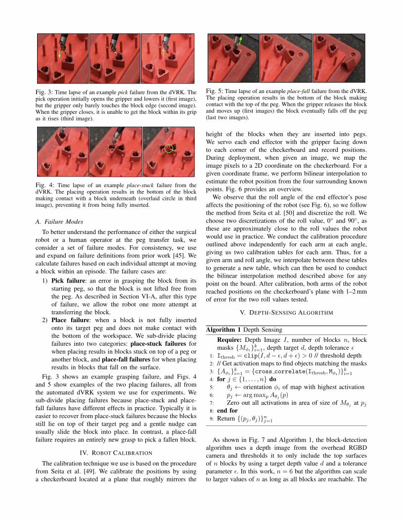
Fig. 3: Time lapse of an example pick failure from the dVRK. Thepick operation initially opens the gripper and lowers it (first image),but the gripper only barely touches the block edge (second image).When the gripper closes, it is unable to get the block within its gripas it rises (third image).
Fig. 4: Time lapse of an example place-stuck failure from thedVRK. The placing operation results in the bottom of the blockmaking contact with a block underneath (overlaid circle in thirdimage), preventing it from being fully inserted.
A. Failure Modes
To better understand the performance of either the surgicalrobot or a human operator at the peg transfer task, weconsider a set of failure modes. For consistency, we useand expand on failure definitions from prior work [45]. Wecalculate failures based on each individual attempt at movinga block within an episode. The failure cases are:
1) Pick failure: an error in grasping the block from itsstarting peg, so that the block is not lifted free fromthe peg. As described in Section VI-A, after this typeof failure, we allow the robot one more attempt attransferring the block.
2) Place failure: when a block is not fully insertedonto its target peg and does not make contact withthe bottom of the workspace. We sub-divide placingfailures into two categories: place-stuck failures forwhen placing results in blocks stuck on top of a peg oranother block, and place-fall failures for when placingresults in blocks that fall on the surface.
Fig. 3 shows an example grasping failure, and Figs. 4and 5 show examples of the two placing failures, all fromthe automated dVRK system we use for experiments. Wesub-divide placing failures because place-stuck and place-fall failures have different effects in practice. Typically it iseasier to recover from place-stuck failures because the blocksstill lie on top of their target peg and a gentle nudge canusually slide the block into place. In contrast, a place-fallfailure requires an entirely new grasp to pick a fallen block.
IV. ROBOT CALIBRATION
The calibration technique we use is based on the procedurefrom Seita et al. [49]. We calibrate the positions by usinga checkerboard located at a plane that roughly mirrors the
Fig. 5: Time lapse of an example place-fall failure from the dVRK.The placing operation results in the bottom of the block makingcontact with the top of the peg. When the gripper releases the blockand moves up (first images) the block eventually falls off the peg(last two images).
height of the blocks when they are inserted into pegs.We servo each end effector with the gripper facing downto each corner of the checkerboard and record positions.During deployment, when given an image, we map theimage pixels to a 2D coordinate on the checkerboard. For agiven coordinate frame, we perform bilinear interpolation toestimate the robot position from the four surrounding knownpoints. Fig. 6 provides an overview.
We observe that the roll angle of the end effector’s poseaffects the positioning of the robot (see Fig. 6), so we followthe method from Seita et al. [50] and discretize the roll. Wechoose two discretizations of the roll value, 0◦ and 90◦, asthese are approximately close to the roll values the robotwould use in practice. We conduct the calibration procedureoutlined above independently for each arm at each angle,giving us two calibration tables for each arm. Thus, for agiven arm and roll angle, we interpolate between these tablesto generate a new table, which can then be used to conductthe bilinear interpolation method described above for anypoint on the board. After calibration, both arms of the robotreached positions on the checkerboard’s plane with 1–2 mmof error for the two roll values tested.
V. DEPTH-SENSING ALGORITHM
Algorithm 1 Depth Sensing
Require: Depth Image I , number of blocks n, blockmasks {Mφi
}ki=1, depth target d, depth tolerance ε1: Ithresh = clip(I, d− ε, d+ ε) > 0 // threshold depth2: // Get activation maps to find objects matching the masks3: {Aφi}ki=1 = {cross correlate(Ithresh, Mφi
)}ki=1
4: for j ∈ {1, . . . , n} do5: θj ← orientation φi of map with highest activation6: pj ← argmaxpAθj (p)7: Zero out all activations in area of size of Mθj at pj8: end for9: Return {(pj , θj)}nj=1
As shown in Fig. 7 and Algorithm 1, the block-detectionalgorithm uses a depth image from the overhead RGBDcamera and thresholds it to only include the top surfacesof n blocks by using a target depth value d and a toleranceparameter ε. In this work, n = 6 but the algorithm can scaleto larger values of n as long as all blocks are reachable. The

Fig. 6: Calibration. Left: when calibrating the dVRK, we use a checkerboard with each edge 16 mm long, and move the robot’s end-effector towards the corners, which are at a known height offset of the peg tips. The right arm moves to all corners included in the overlaidblue grid above, while the arm to the left would be calibrated independently and go to all points in the overlaid green grid. At a givenposition, however, rotating the robot’s arm will result in the tip being at a different location. For example, the second image shows thetip at a checkerboard corner, and the third image shows the result when rotating the roll angle by 90◦, which means the actual tip is at aspot 2–4 mm away. For this reason, we discretize the roll angle and calibrate once per roll angle discretization.
(a) RGB image (b) Depth image (c) Output of depth-sensing algorithm
Fig. 7: Images as seen through the overhead RGBD camera (i.e., the depth sensor is not attached to the robot arm), and subsequentlyprocessed for later usage. Images (a) and (b) show sample RGB and depth images, respectively, that we might get at the beginning of anepisode, where all pegs are informally dropped in the left half of the peg board. In (a), several blocks exhibit specular reflections that onemight find in a surgical setting and could hinder other sensing methods. The board, pegs, and blocks are painted red. Image (c) showsthe 12 detected pegs, circled in blue, along 6 grasp points (left half) and 6 place points (right half), all 12 of which are circled white. Tothe left, image (c) shows the location of the blocks that are within a pre-determined depth interval for block heights. Finally, 12 contoursof the blocks are overlaid. To perform an episode, we follow a pre-determined order of grasp and place movements based on the whitecircles, and repeat the process going from right to left.
Algorithm 2 Grasp Planner
Require: Block pose (pblock, θ), Arm A ∈ {left, right},Peg location ppeg
1: (s1, s2)← closest two (out of three) sides to A2: G ← 2 grasp candidates along s1 and s23: Return argmaxg∈G ‖g − ppeg‖2
algorithm then cross-correlates the thresholded image withpre-computed masks {Mφi
}ki=1 of the block rotated in 30different orientations in the plane of the image. The algorithmthen proceeds iteratively to find the blocks. The best match atiteration j is saved as a pixel coordinate pj = (uj , vj) andorientation θj . The procedure zeroes out the region of thethresholded image occupied by the best match’s mask thenproceeds to the next iteration to find the next best match.We find the peg locations in a similar way. By computingcross-correlations with masks of the target objects (blocks,pegs), we are searching the image for objects that match thegeometry of the target. Algorithm 1 is implemented usingSciPy [5] signal processing code.
After detecting the blocks, we compute grasps (Algo-rithm 2) by first sub-dividing each block edge into twopotential grasp points, for a total of six potential grasp pointsper block. We select the two sides that are closest to the endeffector’s current position; this is to prevent having the robotreach “behind” a peg. Of the grasp points on those edges, weselect the grasp point furthest from the peg to get the mostclearance for an open gripper and thus decreases the chancesof collisions with pegs. Fig. 7 shows an example setup ofRGB and depth images and the corresponding proposed pickand place points circled in white, for the single-arm case.
VI. TRAJECTORY MOTION FOR GRASPING
After the block detection and grasp analysis, the systemmoves blocks from one set of pegs to another in a predefinedorder, iterating through motions from block grasp points toplacement points until all blocks are moved.
For a given grasp point, the system commands the gripperto go slightly above the grasp point with a closed gripper.Then, the system opens the gripper, lowers it, closes thegripper, and raises it (ideally with the block). The systemthen moves the block over its placement point and opens the

Fig. 8: A visualization of the dVRK’s gripper as it picks up a block. In the first two images, an arm that descends to grasp a blockwith an open gripper can risk colliding with the top of the peg (circled above) and damage the hardware. To avoid this, as shown in thesequence in the last three images, the gripper is kept closed until the tip surpasses the height of the peg (dashed line) and then it opens,allowing for safer grasping of a block.
gripper, dropping the block on to a peg. This full motionsequence is executed in an open loop without feedback orvisual servoing, and thus depends on accurate calibration.
Extending to the bilateral-arm case, we select an orderingof the pegs/blocks for both arms such that they do not collidewith each other during the trajectory; the left and right armsgo to two neighboring pegs, such that each arm grasps theblock closest to it. By simultaneously commanding both armsmotions, the robot never makes motions that cross over eachother, thus avoiding arm-to-arm collisions.
The gripper remains closed during most motions, reducingthe chances that motion, block detection, or calibration errorswill result in the gripper colliding with a block or peg. Initialpeg transfer trials showed a danger in that an open grippercould hit the top of a peg, and the resulting force appliedfrom the dVRK’s arm to its gripper could damage a cable(Fig. 8). The safety measure of keeping the gripper closedwas sufficient to avoid gripper-on-peg collisions.
All motions in the peg transfer system require adding abit of extra clearance to add a safety margin to overcomea limitation we encountered when commanding the robot’smotions in terms of the gripper pose. The robot internalcontrol software translates poses into joint angles through thecalculation of the inverse kinematics. We have observed that,while this software achieves poses accurately, pose-to-posemotions are linear interpolations in joint angles, and not inthe gripper’s pose. Due to the non-linear translation betweenpose and joint angles, this linear-in-joint-space interpolationresults in non-linear motions of the end effector. By addingextra clearance to every pose, we add a safety margin andreduce failures. However, this may result in motions that areless efficient than possible were we to instead command therobot using more advanced motion planning and trajectoryoptimization techniques, as we plan to do in future work.
A. Error Recovery Stage
When a pick failure occurs, the block often still remains inits original peg. After the first set of block transfer attempts,we perform a scan through the six known starting blockpositions, and detect if any still remain, and allow the dVRKa second attempt to grasp each block if needed. (In principle,this process could repeat ad infinitum, but we found that therobot would often make similar errors in subsequent actions,so we limit to two attempts.)
TABLE I: Results from experiments for both the single andbilateral arm cases, with 20 and 5 episodes, respectively. We reportthe success rate over the number of total block transfer attempts(236 and 59, respectively), along with the average time for eachof those attempts. In addition, we report the fraction of the threefailure modes on each block transfer attempt.
Task Success Rate Time (s) Pick Stuck FallSingle 0.869 (205/236) 10.02 0.013 0.072 0.046Bilateral 0.780 (46/59) 5.72 0.034 0.068 0.119
VII. EXPERIMENTS AND RESULTS
We initialize a peg transfer task episode by randomlydropping six blocks on the six pegs on the left side of thepeg board, producing variation in the pose of each block. Weevaluate failures as described in Section III-A, abbreviatingfailure modes as Pick (pick failures), Stuck (place-stuckfailures) and Fall (place-fall failures).
A. Single-Arm Results
We perform 20 episodes of the single arm case with thedVRK, and report results in Table I. Across all 20 episodes,the robot performed 236 total attempts at moving a blockfrom one half of the board to another, each of which took10.02 seconds on average. A “perfect” episode with nofailures involves 12 total attempts (6 per direction). Thenumber of attempts in a given episode may be higher orlower depending on if repeated grasp attempts are neededor if placing failures occur during the first set of six blocktransfer attempts. For those 236 block attempts, we recorded31 failure cases, of which 3 were pick failures, 17 were place-stuck failures, and 11 were place-fall failures. The successrate for a single block attempt is thus 205/236 = 86.9 %.For 4 of the 20 episodes, the dVRK executed the entiretask without failures. Each full episode lasted 118.2 ± 9.4seconds, which is nearly twice as long compared to thehuman operator (Section VII-C), and is in part due to thesafety checks that are built into the motion planning. Theproject website contains videos of full episodes.
B. Bilateral Results
We also study a bilateral case, where the second armis the same instrument type as the arm used in the singleexperiment, and run for five episodes. As the two arms canboth move their blocks simultaneously, the average lengthof each full episode is shorter, and was timed at 67.6± 7.3seconds. The bilateral case raises the possibility of having a

TABLE II: Physical experiments from Dr. Danyal Fer for thesingle and bilateral arm cases, with two episodes each. Results arepresented in a similar manner as in Table I.
Task Success Rate Time (s) Pick Stuck FallSingle 0.958 (23/24) 5.08 0.000 0.042 0.000Bilateral 0.833 (20/24) 3.45 0.046 0.125 0.000
failure case with collisions among the arms, but we did notexperience any due to carefully chosen block orderings asdescribed in Section VI.
Over 5 episodes, the success rate of block transfer attemptswas 46/59 = 78.0 % (Table I). We ran these episodes after thesingle-arm case, and there may have been extra wear and tear.Furthermore, the bilateral results require slight adjustmentsof the placing angle for each block to avoid arms and blockscolliding with each other, which may increase the chancesof placing errors. Across the 59 attempts, there were 2 pick,4 place-stuck, and 7 place-fall failures.
C. Human Surgeon Teleop
Dr. Danyal Fer, a surgical resident, performed twoepisodes of the single- and double-arm peg transfer tasksfollowing the same experiment protocol and setup as theautomated system. Table II summarizes peg transfer resultsfrom Dr. Fer. In addition, Appendix I has results on Dr. Fer’scorresponding episodes for the task with standard, off-the-shelf FLS peg transfer materials that were not painted red,and thus were less sticky and allowed for more color cues.
Dr. Fer did not experience any place-fall failures in hisepisodes, but had one failure (place-stuck) in the single-armcase and four failures (one grasp, three place-stuck) in thebilateral case. Some of Dr. Fer’s placing attempts resultedin the block hitting part of the target peg, but he recoveredby raising the block and repeating the placing motion, thusavoiding failures. Dr. Fer completed the single- and bilateral-arm trials in 61.0 ± 3.0 and 41.5 ± 4.9 seconds, which issignificantly faster than the automated system.
D. Failure Cases
The vast majority of the dVRK’s failures were placingfailures (28 for single-arm, 11 for double-arm), such as thoseshown in Figs. 4 and 5). Placing is challenging because, evenif we command the robot to drop at a fixed target for eachpeg, the orientation of the gripped block varies at the timeof release. Dr. Fer was able to more reliably avoid placingfailures because he could react in real time in case his initialplacing did not fully insert the block into a peg.
A place-stuck failure is not as severe as a fallen block,because a gentle nudge can slide the block in place. Inthe dVRK experiments, we observed that several place-stuck cases were unintentionally “corrected” by a subsequentaction, which either knocked the block into the peg orremoved an underlying block that prevented full insertion. Ifwe count those “corrected” blocks as successes, the dVRK’ssuccess rate for the single- and bilateral-arm setups wouldbe 210/236 = 89.0 % and 49/59 = 83.1 %.
VIII. DISCUSSION AND FUTURE WORK
In this paper, we explore the potential for depth sensingin automating the FLS peg transfer task. We demonstratea proof of concept of the procedure and show how usinga high-quality depth camera and calibration can allow a daVinci surgical robot to autonomously perform the task with86.9 % and 78.0 % success rates (single- and bilateral-arms,respectively). Results suggest depth-sensing can be effectivefor automated peg transfer but there remains a significantgap between automated and expert human performance.
In future work, we will address placing failures. Wewill use more sophisticated calibration [50], motion-planning [24], visual servoing [22], and error recovery tech-niques using the depth-sensor and tactile feedback fromjoint motor currents to enhance error detection precisionand speed. We will also explore the use of a surgical robotsimulator to run reinforcement learning [6], [43], [54] to trainclosed-loop controllers for the task, and will additionallyuse ideas from deep reinforcement learning for placing andinsertion tasks [58], [47].
ACKNOWLEDGMENTS
This research was performed at the AUTOLAB at UC Berkeleyin affiliation with the Berkeley AI Research (BAIR) Lab, BerkeleyDeep Drive (BDD), the Real-Time Intelligent Secure Execution(RISE) Lab, the CITRIS “People and Robots” (CPAR) Initiative,and with UC Berkeley’s Center for Automation and Learning forMedical Robotics (Cal-MR). The authors were supported in partby donations from SRI International, Siemens, Google, ToyotaResearch Institute, Honda, Intel, and Intuitive Surgical. The da VinciResearch Kit was supported by the National Science Foundation,via the National Robotics Initiative (NRI), as part of the collabora-tive research project “Software Framework for Research in Semi-Autonomous Teleoperation” between The Johns Hopkins University(IIS 1637789), Worcester Polytechnic Institute (IIS 1637759), andthe University of Washington (IIS 1637444). Daniel Seita is sup-ported by a National Physical Science Consortium Fellowship.
APPENDIX IHUMAN OPERATOR ON NON-PAINTED CASE
TABLE III: Physical experiments from Dr. Danyal Fer on the pegtransfer task setup without the red paint. Results are presented in asimilar manner as in Table I.
Task Success Rate Time (s) Pick Stuck FallSingle 1.000 (120/120) 4.61 0.000 0.000 0.000Bilateral 0.959 (117/122) 2.71 0.016 0.025 0.000
As an extra comparison, Table III reports results fromDr. Fer using the non-painted setup. This version allows forstronger color cues, avoids sticky red paint, and is closerto the standard FLS peg transfer task. Results indicate thatDr. Fer’s performance in this case is superior to that of thepainted setup, with success rates of 100.0 % and 95.9 % forthe single and bilateral arm setups (versus 95.8 % and 83.3 %with red paint), along with faster block attempts of 4.61 s and2.71 s (versus 5.08 s and 3.45 s with red paint). He completedepisodes in 55.3± 4.5 and 33.0± 3.4 seconds, respectively.

REFERENCES
[1] A. Abiri, J. Pensa, A. Tao, J. Ma, Y.-Y. Juo, S. J. Askari, J. Bisley,J. Rosen, E. P. Dutson, and W. S. Grundfest, “Multi-Modal HapticFeedback for Grip Force Reduction in Robotic Surgery,” ScientificReports, vol. 9, no. 1, p. 5016, 2019.
[2] F. Alambeigi, Z. Wang, R. Hegeman, Y.-H. Liu, and M. Armand,“A Robust Data-driven Approach for Online Learning and Manipula-tion of Unmodeled 3-D Heterogeneous Compliant Objects,” in IEEERobotics and Automation Letters (RA-L), 2018.
[3] G. Ballantyne and F. Moll, “The da Vinci Telerobotic Surgical System:The Virtual Operative Field and Telepresence Surgery,” SurgicalClinics of North America, vol. 83, no. 6, pp. 1293–1304, 2003.
[4] R. A. Beasley, “Medical Robots: Current Systems and ResearchDirections,” Journal of Robotics, 2012.
[5] E. Bressert, SciPy and NumPy: an overview for developers. ” O’ReillyMedia, Inc.”, 2012.
[6] G. Brockman, V. Cheung, L. Pettersson, J. Schneider, J. Schulman,J. Tang, and W. Zaremba, “OpenAI Gym,” 2016.
[7] J. D. Brown, C. E. O’Brien, S. C. Leung, K. R. Dumon, D. I.Lee, and K. Kuchenbecker, “Using Contact Forces and Robot ArmAccelerations to Automatically Rate Surgeon Skill at Peg Transfer,”in IEEE Transactions on Biomedical Engineering, 2017.
[8] S. L. Chang, A. S. Kibel, J. D. Brooks, and B. I. Chung, “The Impactof Robotic Surgery on the Surgical Management of Prostate Cancerin the USA,” BJU International, vol. 115, no. 6, 2014.
[9] D.-L. Chow and W. Newman, “Improved Knot-Tying Methods forAutonomous Robot Surgery,” in IEEE Conference on AutomationScience and Engineering (CASE), 2013.
[10] B. Chughtai, D. Scherr, J. D. Pizzo, M. Herman, C. Barbieri, J. Mao,A. Isaacs, R. Lee, A. E. Te, S. A. Kaplan, P. Schlegel, and A. Se-drakyan, “National Trends and Cost of Minimally Invasive Surgery inUrology,” Urology Practice, vol. 2, no. 2, 2015.
[11] A. M. Derossis, G. M. Fried, M. Abrahamowicz, H. H. Sigman, J. S.Barkun, and J. L. Meakins, “Development of a Model for Training andEvaluation of Laparoscopic Skills,” The American Journal of Surgery,vol. 175, no. 6, 1998.
[12] C. D’Ettorre, G. Dwyer, X. Du, F. Chadebecq, F. Vasconcelos,E. De Momi, and D. Stoyanov, “Automated Pick-up of SuturingNeedles for Robotic Surgical Assistance,” in IEEE InternationalConference on Robotics and Automation (ICRA), 2018.
[13] G. M. Fried, L. S. Feldman, M. C. Vassiliou, S. A. Fraser, D. Stan-bridge, G. Ghitulescu, and C. G. Andrew, “Proving the Value ofSimulation in Laparoscopic Surgery,” Annals of Surgery, vol. 240,no. 3, 2004.
[14] A. Garg, S. Sen, R. Kapadia, Y. Jen, S. McKinley, L. Miller, andK. Goldberg, “Tumor Localization using Automated Palpation withGaussian Process Adaptive Sampling,” in IEEE Conference on Au-tomation Science and Engineering (CASE), 2016.
[15] M. Haghighipanah, M. Miyasaka, Y. Li, and B. Hannaford, “UnscentedKalman Filter and 3D Vision to Improve Cable Driven SurgicalRobot Joint Angle Estimation,” in IEEE International Conference onRobotics and Automation (ICRA), 2016.
[16] B. Hannaford, J. Rosen, D. Friedman, H. King, P. Roan, L. Cheng,D. Glozman, J. Ma, S. Kosari, and L. White, “Raven-II: An OpenPlatform for Surgical Robotics Research,” in IEEE Transactions onBiomedical Engineering, 2013.
[17] J. J. Ji, S. Krishnan, V. Patel, D. Fer, and K. Goldberg, “Learning 2DSurgical Camera Motion From Demonstrations,” in IEEE Conferenceon Automation Science and Engineering (CASE), 2018.
[18] H. Kang and J. Wen, “Robotic Knot Tying in Minimally Invasive Surg-eries,” in IEEE/RSJ International Conference on Intelligent Robots andSystems (IROS), 2002.
[19] Y. Kassahun, B. Yu, A. T. Tibebu, D. Stoyanov, S. Giannarou, J. H.Metzen, and E. V. Poorten, “Surgical Robotics Beyond EnhancedDexterity Instrumentation: a Survey of Machine Learning Techniquesand Their Role in Intelligent and Autonomous Surgical Actions,”Journal of Computer Assisted Radiology and Surgery, 2016.
[20] P. Kazanzides, Z. Chen, A. Deguet, G. Fischer, R. Taylor, andS. DiMaio, “An Open-Source Research Kit for the da Vinci SurgicalSystem,” in IEEE International Conference on Robotics and Automa-tion (ICRA), 2014.
[21] B. Kehoe, G. Kahn, J. Mahler, J. Kim, A. Lee, A. Lee, K. Naka-gawa, S. Patil, W. Boyd, P. Abbeel, and K. Goldberg, “AutonomousMultilateral Debridement with the Raven Surgical Robot,” in IEEEInternational Conference on Robotics and Automation (ICRA), 2014.
[22] D. Kragic and H. I. Christensen, “Survey on Visual Servoing forManipulation.” 2002.
[23] S. Krishnan, R. Fox, I. Stoica, and K. Goldberg, “DDCO: Discovery ofDeep Continuous Options for Robot Learning from Demonstrations,”in Conference on Robot Learning (CoRL), 2017.
[24] J.-C. Latombe, Robot Motion Planning. Kluwer Academic Publishers,1991.
[25] Y. Li, F. Richter, J. Lu, E. K. Funk, R. K. Orosco, J. Zhu, and M. C.Yip, “SuPer: A Surgical Perception Framework for Endoscopic TissueManipulation with Surgical Robotics,” arXiv:1909.05405, 2019.
[26] N. Madapana, M. M. Rahman, N. Sanchez-Tamayo, M. V. Balakuntala,G. Gonzalez, J. P. Bindu, L. Venkatesh, X. Zhang, J. B. Noguera,T. Low et al., “DESK: A Robotic Activity Dataset for DexterousSurgical Skills Transfer to Medical Robots,” in IEEE/RSJ InternationalConference on Intelligent Robots and Systems (IROS), 2019.
[27] J. Mahler, S. Krishnan, M. Laskey, S. Sen, A. Murali, B. Kehoe,S. Patil, J. Wang, M. Franklin, P. Abbeel, and K. Goldberg, “LearningAccurate Kinematic Control of Cable-Driven Surgical Robots UsingData Cleaning and Gaussian Process Regression.” in IEEE Conferenceon Automation Science and Engineering (CASE), 2014.
[28] J. Mahler, J. Liang, S. Niyaz, M. Laskey, R. Doan, X. Liu, J. A. Ojea,and K. Goldberg, “Dex-Net 2.0: Deep Learning to Plan Robust Graspswith Synthetic Point Clouds and Analytic Grasp Metrics,” in Robotics:Science and Systems (RSS), 2017.
[29] S. McKinley, A. Garg, S. Sen, D. V. Gealy, J. P. McKinley, Y. Jen,M. Guo, D. Boyd, and K. Goldberg, “An Interchangeable SurgicalInstrument System with Application to Supervised Automation ofMultilateral Tumor Resection,” in IEEE Conference on AutomationScience and Engineering (CASE), 2016.
[30] S. McKinley, A. Garg, S. Sen, R. Kapadia, A. Murali, K. Nichols,S. Lim, S. Patil, P. Abbeel, A. M. Okamura, and K. Goldberg,“A Disposable Haptic Palpation Probe for Locating SubcutaneousBlood Vessels in Robot-Assisted Minimally Invasive Surgery,” in IEEEConference on Automation Science and Engineering (CASE), 2015.
[31] M. Miyasaka, J. Matheson, A. Lewis, and B. Hannaford, “Mea-surement of the Cable-Pulley Coulomb and Viscous Friction for aCable-Driven Surgical Robotic System,” in IEEE/RSJ InternationalConference on Intelligent Robots and Systems (IROS), 2015.
[32] G. Moustris, S. Hiridis, K. Deliparaschos, and K. Konstantinidis,“Evolution of Autonomous and Semi-Autonomous Robotic SurgicalSystems: A Review of the Literature,” International Journal of Med-ical Robotics and Computer Assisted Surgery, vol. 7, 2011.
[33] A. Murali, A. Garg, S. Krishnan, F. T. Pokorny, P. Abbeel, T. Darrell,and K. Goldberg, “TSC-DL: Unsupervised Trajectory Segmentation ofMulti-Modal Surgical Demonstrations with Deep Learning,” in IEEEInternational Conference on Robotics and Automation (ICRA), 2016.
[34] A. Murali, S. Sen, B. Kehoe, A. Garg, S. McFarland, S. Patil, W. D.Boyd, S. Lim, P. Abbeel, and K. Goldberg, “Learning by Observationfor Surgical Subtasks: Multilateral Cutting of 3D Viscoelastic and 2DOrthotropic Tissue Phantoms,” in IEEE International Conference onRobotics and Automation (ICRA), 2015.
[35] T. Osa, N. Sugita, and M. Mitsuishi, “Online Trajectory Planning inDynamic Environments for Surgical Task Automation,” in Robotics:Science and Systems (RSS), 2014.
[36] L. Panait, S. Shetty, P. Shewokits, and J. A. Sanchez, “Do La-paroscopic Skills Transfer to Robotic Surgery?” Journal of SurgicalResearch, 2014.
[37] P. Pastor, M. Kalakrishnan, J. Binney, J. Kelly, L. Righetti,G. Sukhatme, and S. Schaal, “Learning Task Error Models for Manipu-lation,” in IEEE International Conference on Robotics and Automation(ICRA), 2013.
[38] V. Patel, S. Krishnan, A. Goncalves, C. Chen, W. D. Boyd, andK. Goldberg, “Using Intermittent Synchronization to Compensatefor Rhythmic Body Motion During Autonomous Surgical Cuttingand Debridement,” in International Symposium on Medical Robotics(ISMR), 2018.
[39] V. Patel, S. Krishnan, A. Goncalves, and K. Goldberg, “SPRK: ALow-cost Stewart Platform for Motion Study in Surgical Robotics,” inInternational Symposium on Medical Robotics (ISMR), 2018.
[40] S. A. Pedram, P. Ferguson, J. Ma, and E. D. J. Rosen, “AutonomousSuturing Via Surgical Robot: An Algorithm for Optimal Selection ofNeedle Diameter, Shape, and Path,” in IEEE International Conferenceon Robotics and Automation (ICRA), 2017.
[41] S. A. Pedram, P. W. Ferguson, C. Shin, A. Mehta, E. P. Dutson,F. Alambeigi, and J. Rosen, “Toward Synergic Learning for Au-

tonomous Manipulation of Deformable Tissues via Surgical Robots:An Approximate Q-Learning Approach,” in arXiv:1910.03398, 2019.
[42] M. M. Rahman, N. Sanchez-Tamayo, G. Gonzalez, M. Agarwal,V. Aggarwal, R. M. Voyles, Y. Xue, and J. Wachs, “Transfer-ring Dexterous Surgical Skill Knowledge between Robots for Semi-autonomous Teleoperation,” in IEEE International Conference onRobot and Human Interactive Communication (Ro-Man), 2019.
[43] F. Richter, R. K. Orosco, and M. C. Yip, “Open-Sourced Re-inforcement Learning Environments for Surgical Robotics,” inarXiv:1903.02090, 2019.
[44] I. Rivas-Blanco, C. J. P. del Pulgar, C. Lopez-Casado, E. Bauzano, andV. F. Munoz, “Transferring Know-How for an Autonomous CameraRobotic Assistant,” Electronics: Cognitive Robotics and Control, 2019.
[45] J. Rosen and J. Ma, “Autonomous Operation in Surgical Robotics,”Mechanical Engineering, vol. 137, no. 9, 2015.
[46] H. Saeidi, H. N. D. Le, J. D. Opfermann, S. Leonard, A. Kim,M. H. Hsieh, J. U. Kang, and A. Krieger, “Autonomous LaparoscopicRobotic Suturing with a Novel Actuated Suturing Tool and 3D Endo-scope,” in IEEE International Conference on Robotics and Automation(ICRA), 2019.
[47] G. Schoettler, A. Nair, J. Luo, S. Bahl, J. A. Ojea, E. Solowjow,and S. Levine, “Deep Reinforcement Learning for Industrial InsertionTasks with Visual Inputs and Natural Rewards,” arXiv:1906.05841,2019.
[48] J. Schulman, A. Gupta, S. Venkatesan, M. Tayson-Frederick, andP. Abbeel, “A Case Study of Trajectory Transfer Through Non-Rigid Registration for a Simplified Suturing Scenario,” in IEEE/RSJInternational Conference on Intelligent Robots and Systems (IROS),2013.
[49] D. Seita, A. Ganapathi, R. Hoque, M. Hwang, E. Cen, A. K. Tanwani,A. Balakrishna, B. Thananjeyan, J. Ichnowski, N. Jamali, K. Yamane,S. Iba, J. Canny, and K. Goldberg, “Deep Imitation Learning ofSequential Fabric Smoothing Policies,” in arXiv:1910.04854, 2019.
[50] D. Seita, S. Krishnan, R. Fox, S. McKinley, J. Canny, and K. Goldberg,“Fast and Reliable Autonomous Surgical Debridement with Cable-Driven Robots Using a Two-Phase Calibration Procedure,” in IEEEInternational Conference on Robotics and Automation (ICRA), 2018.
[51] S. Sen, A. Garg, D. V. Gealy, S. McKinley, Y. Jen, and K. Goldberg,“Automating Multiple-Throw Multilateral Surgical Suturing with aMechanical Needle Guide and Sequential Convex Optimization,” inIEEE International Conference on Robotics and Automation (ICRA),2016.
[52] C. Shin, P. W. Ferguson, S. A. Pedram, J. Ma, E. P. Dutson, andJ. Rosen, “Autonomous Tissue Manipulation via Surgical Robot UsingLearning Based Model Predictive Control,” in IEEE InternationalConference on Robotics and Automation (ICRA), 2019.
[53] P. Sundaresan, B. Thananjeyan, J. Chiu, D. Fer, and K. Goldberg,“Automated Extraction of Surgical Needles from Tissue Phantoms,”in IEEE Conference on Automation Science and Engineering (CASE),2019.
[54] R. S. Sutton and A. G. Barto, Introduction to Reinforcement Learning,2nd ed. Cambridge, MA, USA: MIT Press, 2018.
[55] B. Thananjeyan, A. Balakrishna, U. Rosolia, F. Li, R. McAllister, J. E.Gonzalez, S. Levine, F. Borrelli, and K. Goldberg, “Safety AugmentedValue Estimation from Demonstrations (SAVED): Safe Deep Model-Based RL for Sparse Cost Robotic Tasks,” arXiv:1905.13402, 2019.
[56] B. Thananjeyan, A. Garg, S. Krishnan, C. Chen, L. Miller, andK. Goldberg, “Multilateral Surgical Pattern Cutting in 2D OrthotropicGauze with Deep Reinforcement Learning Policies for Tensioning,” inIEEE International Conference on Robotics and Automation (ICRA),2017.
[57] J. Van Den Berg, S. Miller, D. Duckworth, H. Hu, A. Wan, X. Fu,K. Goldberg, and P. Abbeel, “Superhuman Performance of Surgi-cal Tasks by Robots using Iterative Learning from Human-GuidedDemonstrations,” in IEEE International Conference on Robotics andAutomation (ICRA), 2010.
[58] M. Vecerik, O. Sushkov, D. Barker, T. Rothorl, T. Hester, andJ. Scholz, “A Practical Approach to Insertion with Variable SocketPosition Using Deep Reinforcement Learning,” in IEEE InternationalConference on Robotics and Automation (ICRA), 2019.
[59] M. Yip and N. Das, “Robot Autonomy for Surgery,” The Encyclopediaof Medical Robotics, 2017.
[60] F. Zhong, Y. Wang, Z. Wang, and Y.-H. Liu, “Dual-Arm RoboticNeedle Insertion With ActiveTissue Deformation for AutonomousSuturing,” in IEEE Robotics and Automation Letters (RA-L), 2019.