Embed Size (px)
Citation preview
Applying Intelligent Fast Load Shed Using IEC 61850 GOOSE
JC Theron, Steven Rowe – GE Grid Solutions
Troy Wilsey, Anthony Colonnese – Ameresco
Russell Gagner – Civilian Naval Facilit ies Engineering Command
71th Texas A&M Conference for Protective Relay Engineers 2018
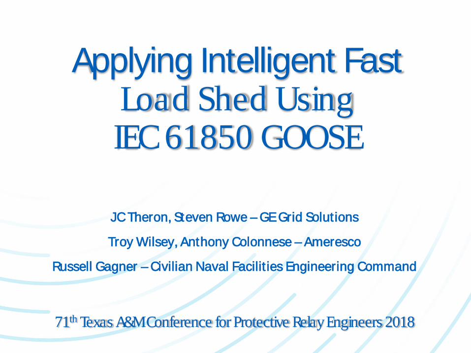
• Introduction/Types of Load Shedding Solutions
• IEC 61850 Fast Load Shed Architecture
• Case Study Fast Load Shed Architecture
• Dynamic Source/Load Power Balancing
• Contingency Operation
• Fast Speed
• Lessons Learned
• Enhancements over Existing Systems
• HMI and DCS Involvement
• Conclusions
Content

• Industrial facilities with co-generation experience large frequency decay if source lost (power-balance disrupted)
• Can cascade – whole local system lost
• Conventional load shedding schemes (>250ms)Underfrequency and dF/dtUndervoltage
• Traditional contingency based load shedding schemes (160 – 400ms)PLC or PC based (centralized)
• Fast load shedding schemes (<150ms)IED or EMS/SCADA basedSource/load power balance calculated
Introduction/Types of Load Shed
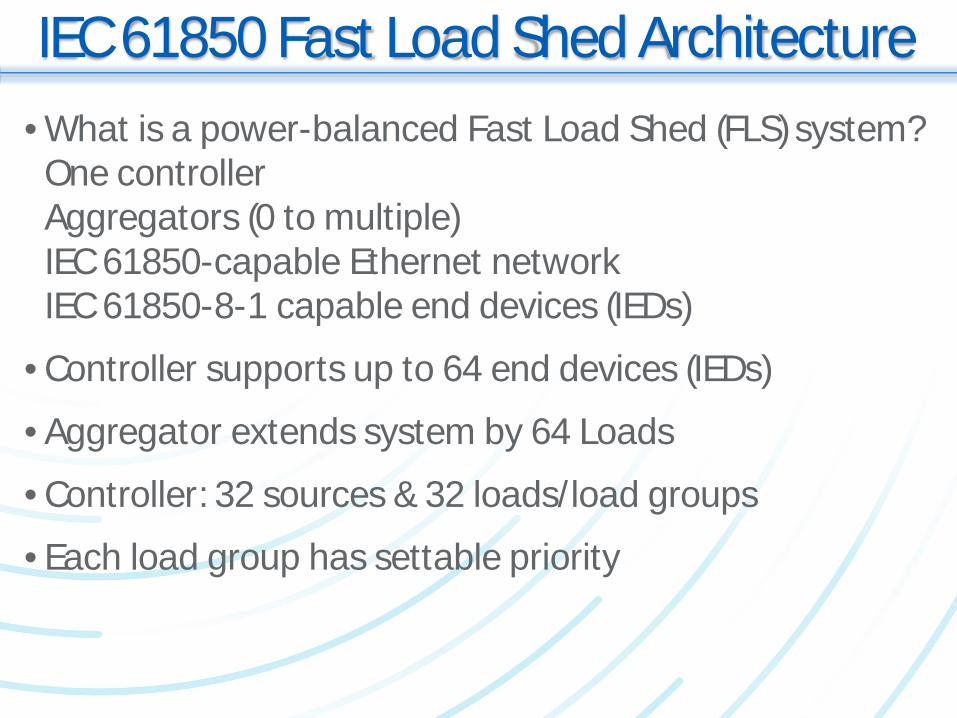
• What is a power-balanced Fast Load Shed (FLS) system?One controllerAggregators (0 to multiple)IEC 61850-capable Ethernet networkIEC 61850-8-1 capable end devices (IEDs)
• Controller supports up to 64 end devices (IEDs)
• Aggregator extends system by 64 Loads
• Controller: 32 sources & 32 loads/load groups
• Each load group has settable priority
IEC 61850 Fast Load Shed Architecture
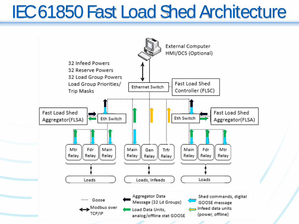
IEC 61850 Fast Load Shed Architecture
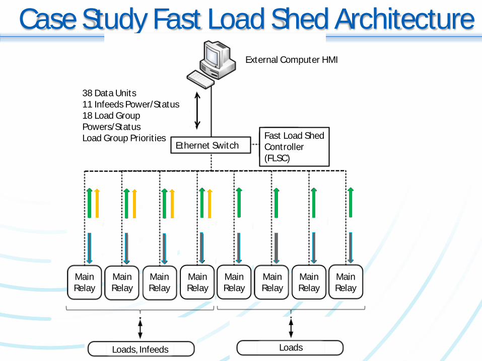
Case Study Fast Load Shed Architecture
38 Data Units11 Infeeds Power/Status18 Load Group Powers/StatusLoad Group Priorit ies
External Computer HMI
Ethernet SwitchFast Load ShedController (FLSC)
MainRelay
Loads, Infeeds Loads
MainRelay
MainRelay
MainRelay
MainRelay
MainRelay
MainRelay
MainRelay
• Goal: re-establish source/load power balance when source power is lost
• Fast Load Shed Controller (FLSC) receives source/load powers once per second
• FLSC calculates power balance
• Checks if generation/source lost exceeds reserve
• Send GOOSE messages to shed Loads per pre-defined priorities above reserve
• FLSC recalculates power balance after contingency time
Dynamic Source/Load P Balance
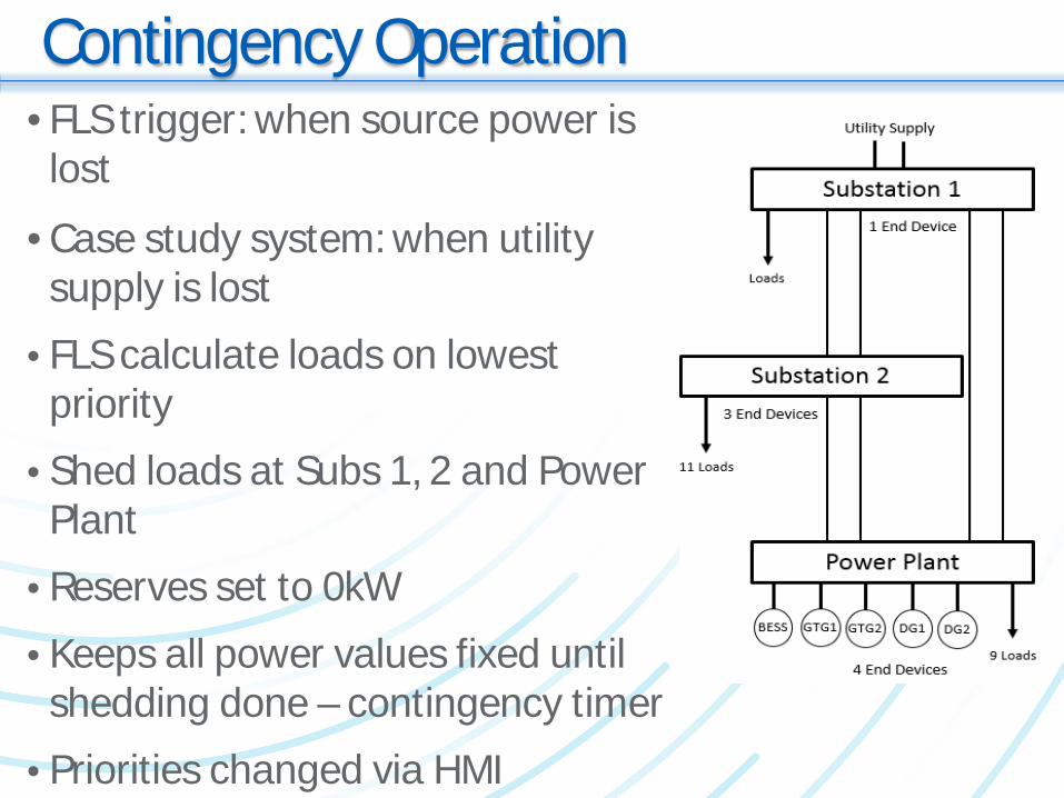
• FLS trigger: when source power is lost
• Case study system: when utility supply is lost
• FLS calculate loads on lowest priority
• Shed loads at Subs 1, 2 and Power Plant
• Reserves set to 0kW• Keeps all power values fixed until shedding done – contingency timer
• Priorities changed via HMI
Contingency Operation
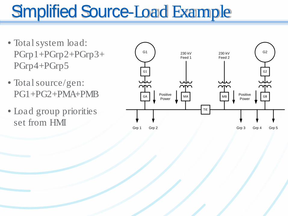
Simplified Source-Load Example
TIE
PositivePower
PositivePower
Grp 1 Grp 2 Grp 3 Grp 4 Grp 5
G1
G1
GA
230 kVFeed 1
MA
230 kVFeed 2
MB
G2
G2
GB
• Total system load: PGrp1+PGrp2+PGrp3+PGrp4+PGrp5
• Total source/gen: PG1+PG2+PMA+PMB
• Load group priorities set from HMI
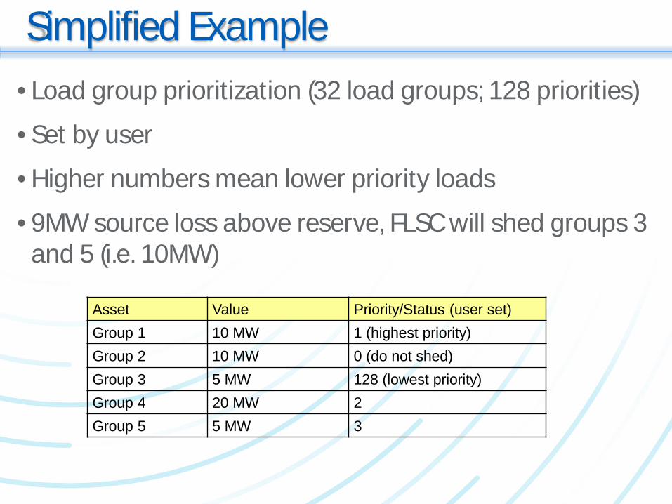
• Load group prioritization (32 load groups; 128 priorities)
• Set by user
• Higher numbers mean lower priority loads
• 9MW source loss above reserve, FLSC will shed groups 3 and 5 (i.e. 10MW)
Simplified Example
Asset Value Priority/Status (user set)Group 1 10 MW 1 (highest priority)Group 2 10 MW 0 (do not shed)Group 3 5 MW 128 (lowest priority)Group 4 20 MW 2Group 5 5 MW 3
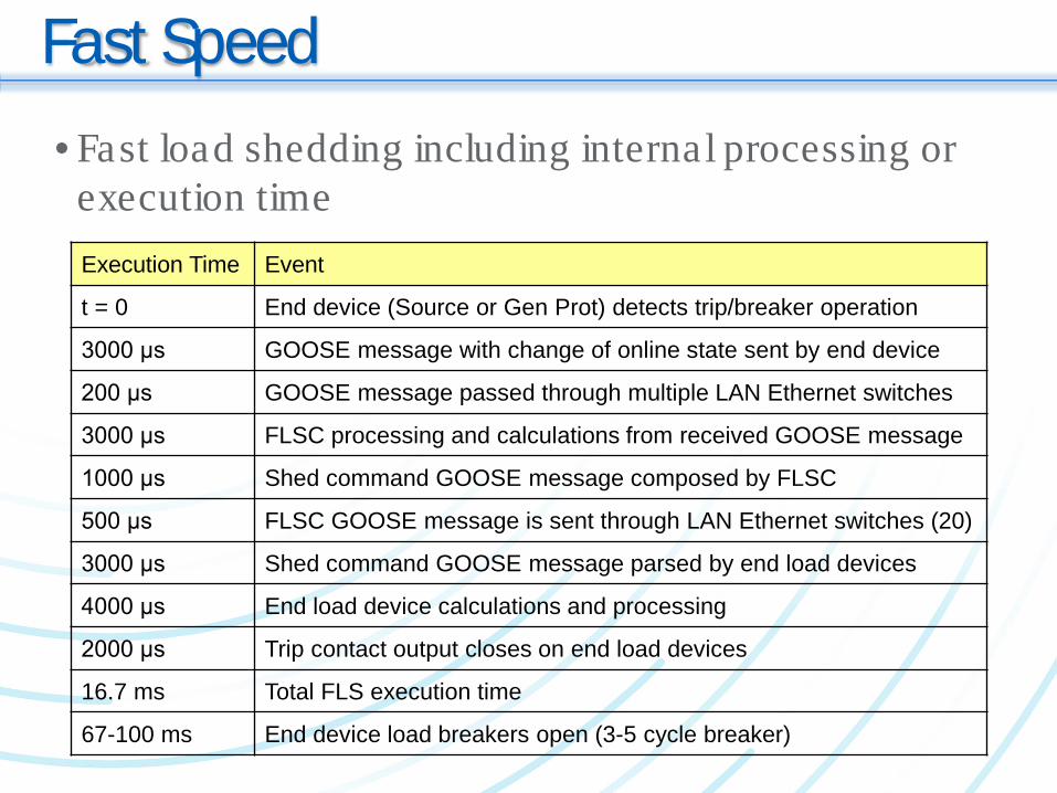
Fast Speed• Fast load shedding including internal processing or
execution time Execution Time Event
t = 0 End device (Source or Gen Prot) detects trip/breaker operation
3000 μs GOOSE message with change of online state sent by end device
200 μs GOOSE message passed through multiple LAN Ethernet switches
3000 μs FLSC processing and calculations from received GOOSE message
1000 μs Shed command GOOSE message composed by FLSC
500 μs FLSC GOOSE message is sent through LAN Ethernet switches (20)
3000 μs Shed command GOOSE message parsed by end load devices
4000 μs End load device calculations and processing
2000 μs Trip contact output closes on end load devices
16.7 ms Total FLS execution time
67-100 ms End device load breakers open (3-5 cycle breaker)
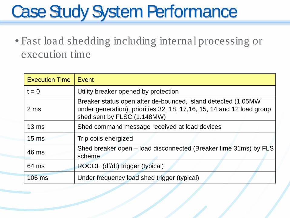
Case Study System Performance• Fast load shedding including internal processing or
execution time
Execution Time Event
t = 0 Utility breaker opened by protection
2 msBreaker status open after de-bounced, island detected (1.05MW under generation), priorities 32, 18, 17,16, 15, 14 and 12 load group shed sent by FLSC (1.148MW)
13 ms Shed command message received at load devices
15 ms Trip coils energized
46 ms Shed breaker open – load disconnected (Breaker time 31ms) by FLS scheme
64 ms ROCOF (df/dt) trigger (typical)
106 ms Under frequency load shed trigger (typical)
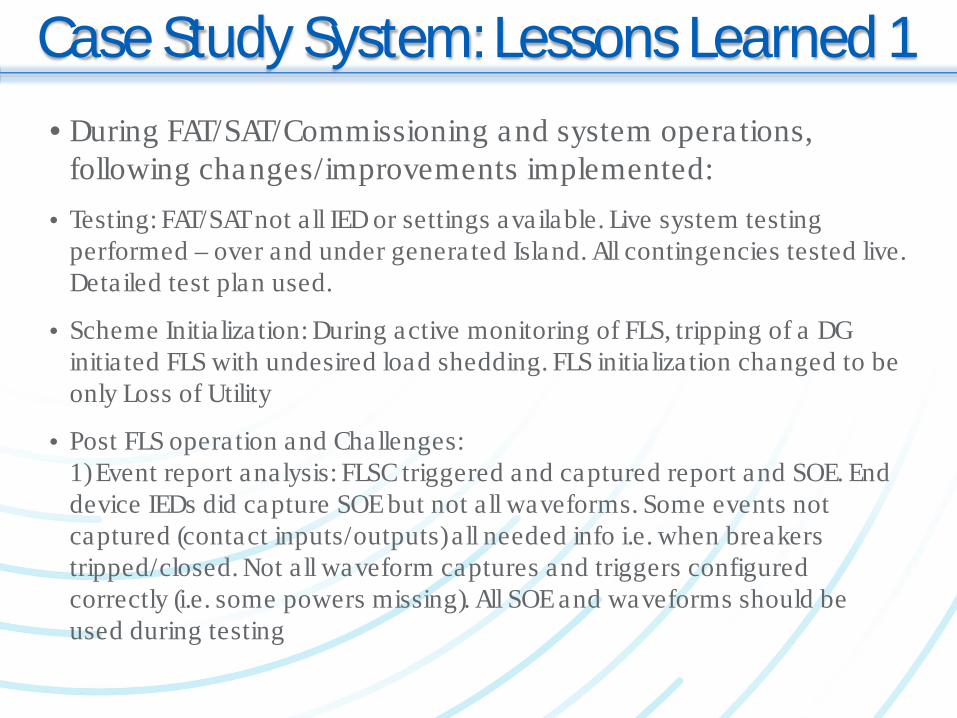
Case Study System: Lessons Learned 1• During FAT/SAT/Commissioning and system operations,
following changes/improvements implemented:• Testing: FAT/SAT not a ll IED or settings available. Live system testing
performed – over and under generated Island. All contingencies tested live. Detailed test plan used.
• Scheme Initia lization: During active monitoring of FLS, tripping of a DG initia ted FLS with undesired load shedding. FLS initia lization changed to be only Loss of Utility
• Post FLS operation and Challenges:1) Event report analysis: FLSC triggered and captured report and SOE. End device IEDs did capture SOE but not a ll waveforms. Some events not captured (contact inputs/outputs) a ll needed info i.e. when breakers tripped/closed. Not a ll waveform captures and triggers configured correctly (i.e. some powers missing). All SOE and waveforms should be used during testing
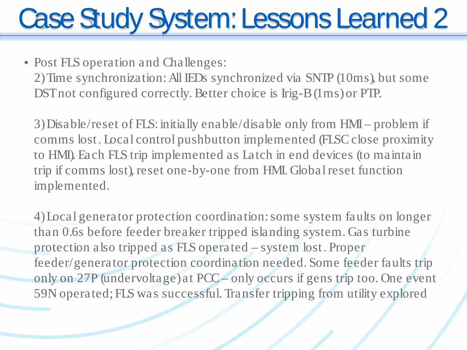
Case Study System: Lessons Learned 2• Post FLS operation and Challenges:
2) Time synchronization: All IEDs synchronized via SNTP (10ms), but some DST not configured correctly. Better choice is Irig-B (1ms) or PTP.
3) Disable/reset of FLS: initia lly enable/disable only from HMI – problem if comms lost . Local control pushbutton implemented (FLSC close proximity to HMI). Each FLS trip implemented as Latch in end devices (to maintain trip if comms lost), reset one-by-one from HMI. Global reset function implemented.
4) Local generator protection coordination: some system faults on longer than 0.6s before feeder breaker tripped islanding system. Gas turbine protection also tripped as FLS operated – system lost . Proper feeder/generator protection coordination needed. Some feeder faults trip only on 27P (undervoltage) a t PCC – only occurs if gens trip too. One event 59N operated; FLS was successful. Transfer tripping from utility explored
Case Study System: Lessons Learned 3• Post FLS operation and Challenges:
5) Use of Synchrophasors: during a FLS event , dynamic changes of local system (Voltages and Frequency) observed at update ra te of IEDs. PMUs can be used to observe/analyze fast dynamic system changes during FLS events
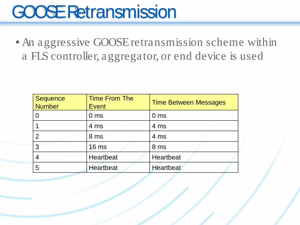
GOOSE Retransmission• An aggressive GOOSE retransmission scheme within
a FLS controller, aggregator, or end device is used
Sequence Number
Time From The Event Time Between Messages
0 0 ms 0 ms1 4 ms 4 ms2 8 ms 4 ms3 16 ms 8 ms4 Heartbeat Heartbeat5 Heartbeat Heartbeat
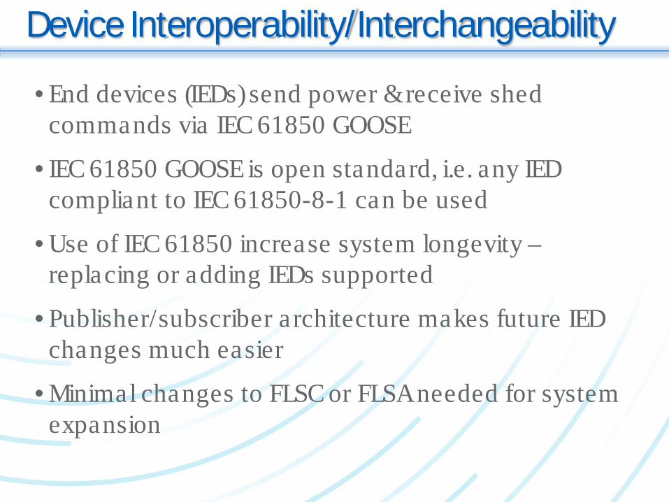
Device Interoperability/Interchangeability
• End devices (IEDs) send power & receive shed commands via IEC 61850 GOOSE
• IEC 61850 GOOSE is open standard, i.e. any IED compliant to IEC 61850-8-1 can be used
• Use of IEC 61850 increase system longevity –replacing or adding IEDs supported
• Publisher/subscriber architecture makes future IED changes much easier
• Minimal changes to FLSC or FLSA needed for system expansion
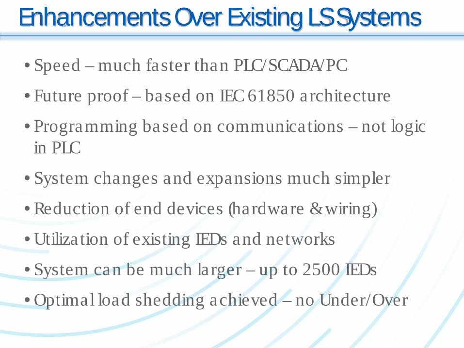
Enhancements Over Existing LS Systems
• Speed – much faster than PLC/SCADA/PC
• Future proof – based on IEC 61850 architecture
• Programming based on communications – not logic in PLC
• System changes and expansions much simpler
• Reduction of end devices (hardware & wiring)
• Utilization of existing IEDs and networks
• System can be much larger – up to 2500 IEDs
• Optimal load shedding achieved – no Under/Over
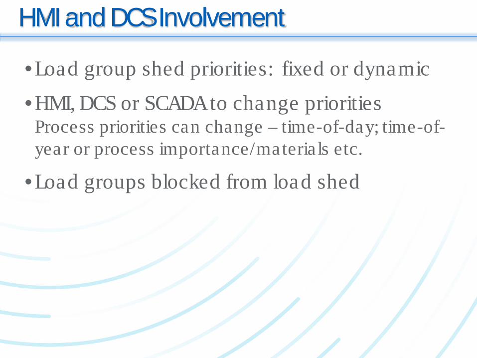
HMI and DCS Involvement
•Load group shed priorities: fixed or dynamic•HMI, DCS or SCADA to change priorities
Process priorities can change – time-of-day; time-of-year or process importance/materia ls etc.
•Load groups blocked from load shed
Conclusions
•Fast Load Shed is essential for industria ls with co-gen for system stability
•Prevents loss of complete system if gen/source is lost
•Fast Load Shed system is proven: Case Study•Several advantages over existing systems•Large and complex systems and expansions more manageable
Thank You
Questions?