Embed Size (px)
Citation preview

© The Aerospace Corporation 2013
Applying the “Test Like You Fly” (TLYF) Process To Flight Software Testing
Julie White Senior Project Engineer Enterprise Mission Assurance Corporate Chief Engineers Office (310) 416-7229 [email protected] Lindsay Tilney Senior Project Leader Software Systems Acquisition Software Systems Assurance Department (310) 336-7104 [email protected]
2
“Like You Fly” (LYF) Is Mostly About the Software
The TLYF Process was created based on lessons learned from a large number of mission failures
• Many of those failures resulted from issues that were either software specific, software – hardware interaction issues, software – software issues, or software – people/process issues
• LYF tests run on testbeds and on flight vehicles predominantly discover software-related issues
• This presentation is intended as a very brief overview of how to apply the TLYF process to software testing

3
Basic Principles & Tenets of the TLYF Process
• First – The system should never experience expected operations,
environments, stresses or their combinations for the first time during the mission
• Second – Do not subject the system to potentially damaging situations
• Third – TLYF complements but does not replace other forms of perceptive
testing (e.g., environmental, stress, performance and functional testing)
• Fourth – When unable to TLYF, manage the critical fault risk
Murphy is alive & well & working overtime on your program!
4
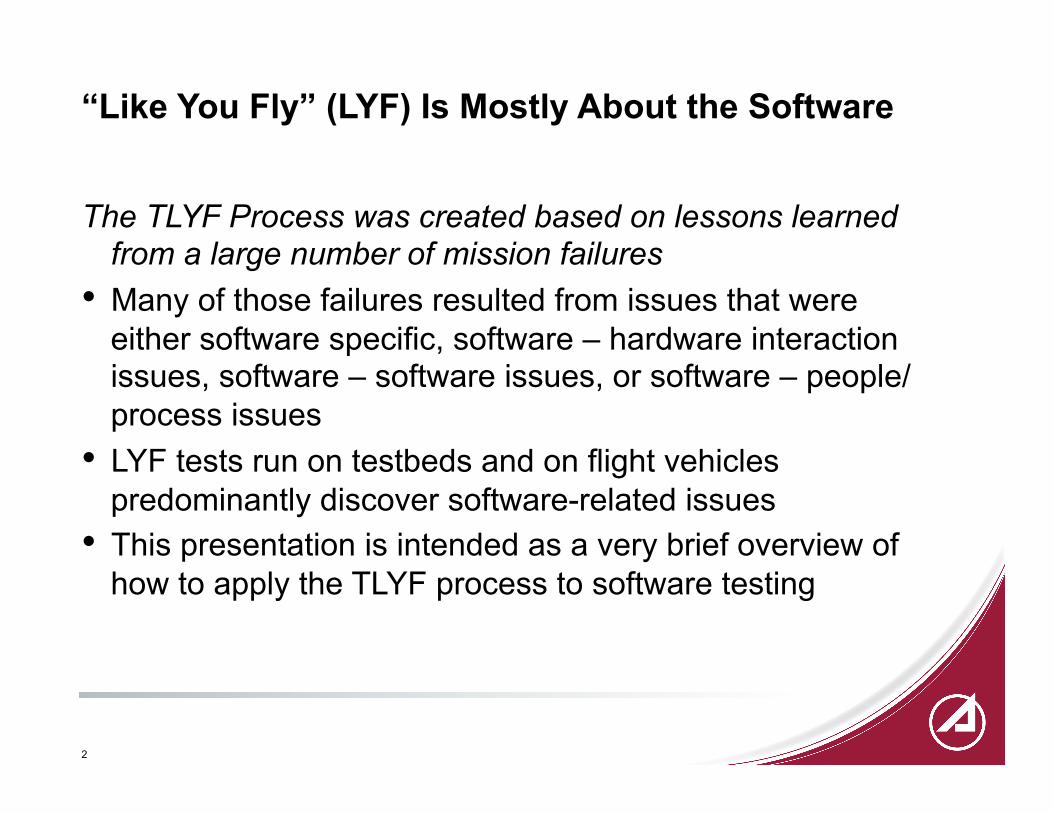
Early On-Orbit Failure Time Distribution Many (most? all?) of the earliest losses are TLYF escapes
40
4 2 1 1
3 0 1 0
2 0 0 1 0
2 0
2 2 1 0
4 1
4
10
0
5
10
15
20
25
30
35
40
45
Days from Launch
# Dead Satellites
Losses Prior to 100 Days Are Frequently Test Escapes
Mars Climate Orbiter
Mars Polar Lander
Accumulation error
“First time” failures
5
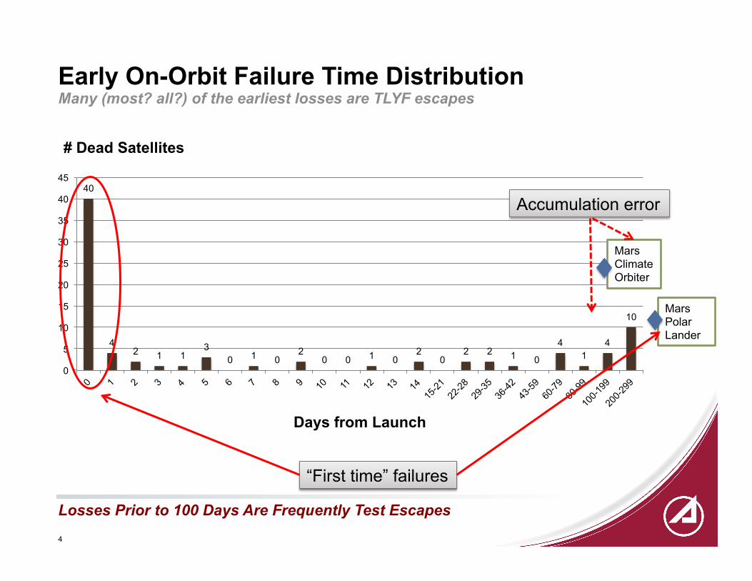
TLYF Implementation Process An Interactive Dual Disciplined Process
Characterize the Mission
Do Mission Critical Fault Analysis
Map Mission to LYF Tests
Perform Critical Fault Risk
Management Design LYF Tests
Execute & Evaluate LYF
Tests
Systems Engineering Test Development
This is first and foremost a systems engineering process
Architect LYF Tests
6
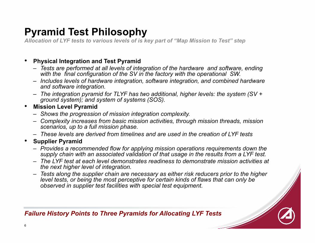
Pyramid Test Philosophy Allocation of LYF tests to various levels of is key part of “Map Mission to Test” step
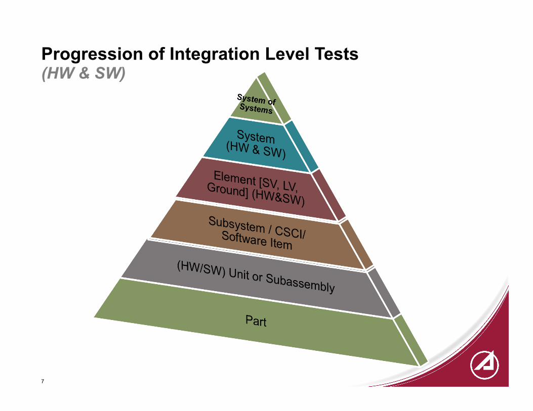
• Physical Integration and Test Pyramid – Tests are performed at all levels of integration of the hardware and software, ending
with the final configuration of the SV in the factory with the operational SW. – Includes levels of hardware integration, software integration, and combined hardware
and software integration. – The integration pyramid for TLYF has two additional, higher levels: the system (SV +
ground system); and system of systems (SOS). • Mission Level Pyramid
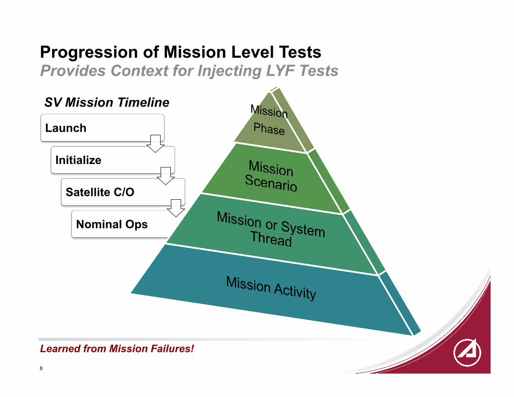
– Shows the progression of mission integration complexity. – Complexity increases from basic mission activities, through mission threads, mission
scenarios, up to a full mission phase. – These levels are derived from timelines and are used in the creation of LYF tests
• Supplier Pyramid – Provides a recommended flow for applying mission operations requirements down the
supply chain with an associated validation of that usage in the results from a LYF test. – The LYF test at each level demonstrates readiness to demonstrate mission activities at
the next higher level of integration. – Tests along the supplier chain are necessary as either risk reducers prior to the higher
level tests, or being the most perceptive for certain kinds of flaws that can only be observed in supplier test facilities with special test equipment.
Failure History Points to Three Pyramids for Allocating LYF Tests
7
Progression of Integration Level Tests (HW & SW)
8
Launch
Initialize
Satellite C/O
Nominal Ops
Provides Context for Injecting LYF Tests Progression of Mission Level Tests
Learned from Mission Failures!
SV Mission Timeline

9
Mission Phases Characterizing the Mission According to Mission Phase Objective
Ascent
Initialization
Orbit transfer
SV C/O
Nominal Operations
Phase Launch / Ascent Orbit Transfer Initialization SV Checkout Nominal Operations
10
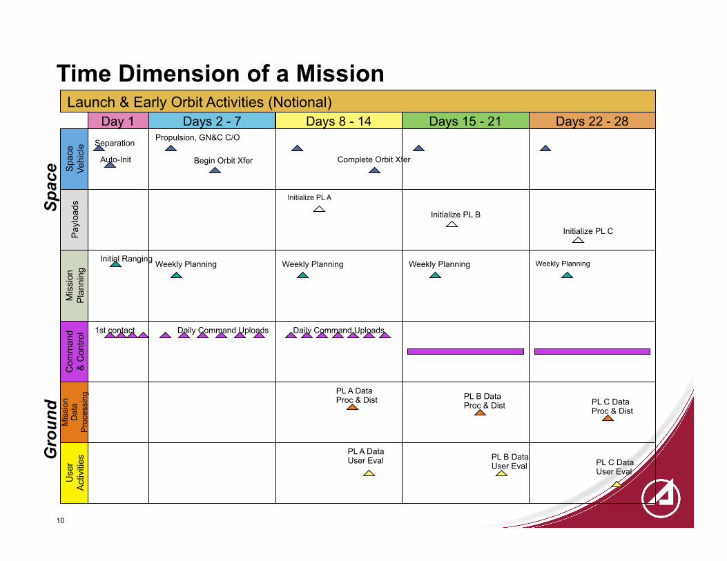
Launch & Early Orbit Activities (Notional)
Daily Command Uploads
PL A Data Proc & Dist
Auto-Init
Spa
ce
Vehi
cle
Pay
load
s M
issi
on
Pla
nnin
g C
omm
and
& C
ontro
l
Mis
sion
D
ata
Pro
cess
ing
Use
r A
ctiv
ities
Day 1 Days 8 - 14 Days 15 - 21 Days 22 - 28 Separation
1st contact
Initial Ranging
Initialize PL A
Initialize PL B
Initialize PL C
Weekly Planning Weekly Planning Weekly Planning Weekly Planning
Begin Orbit Xfer
Propulsion, GN&C C/O
Days 2 - 7
Complete Orbit Xfer
PL B Data Proc & Dist PL C Data
Proc & Dist
PL A Data User Eval PL B Data
User Eval PL C Data User Eval
Daily Command Uploads
Time Dimension of a Mission G
roun
d S
pace

11
Ascent Phase – Launch Events Example
Courtesy NASA/JPL-Caltech
Launch Ascent Profile

12
Ascent First Time & Mission Critical Events & Activities Example - Space Vehicle and Launch Vehicle
Ascent (Space Vehicle) Timeline Critical Event
Prelaunch Spacecraft computer unit (SCU)
Database upload
SW patch upload
Initialize configuration for launch
Switch to internal power
T + 0 Launch signal for SCU timer
T + 837 sec Turn on SGLS transmitters
T + 58 min Separation
Timeline Critical Event
Prelaunch Initialize configuration for launch
T + 0 Liftoff
T + 82.5 sec GEM jettison
T + 264 sec Main Engine Cutoff
T + 277.5 sec Second stage ignition
T + 281.5 sec Fairing jettison
T + 685.1 sec Secondary Engine Cutoff
T + 58 min Separation
Ascent (Launch Vehicle)
13
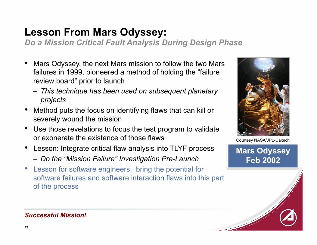
Lesson From Mars Odyssey: Do a Mission Critical Fault Analysis During Design Phase
• Mars Odyssey, the next Mars mission to follow the two Mars failures in 1999, pioneered a method of holding the “failure review board” prior to launch – This technique has been used on subsequent planetary
projects • Method puts the focus on identifying flaws that can kill or
severely wound the mission • Use those revelations to focus the test program to validate
or exonerate the existence of those flaws • Lesson: Integrate critical flaw analysis into TLYF process
– Do the “Mission Failure” Investigation Pre-Launch • Lesson for software engineers: bring the potential for
software failures and software interaction flaws into this part of the process
Successful Mission!
Courtesy NASA/JPL-Caltech
Mars Odyssey Feb 2002
14
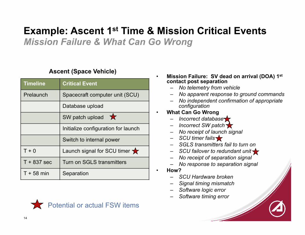
Example: Ascent 1st Time & Mission Critical Events Mission Failure & What Can Go Wrong
• Mission Failure: SV dead on arrival (DOA) 1st contact post separation
– No telemetry from vehicle – No apparent response to ground commands – No independent confirmation of appropriate
configuration • What Can Go Wrong
– Incorrect database – Incorrect SW patch – No receipt of launch signal – SCU timer fails – SGLS transmitters fail to turn on – SCU failover to redundant unit – No receipt of separation signal – No response to separation signal
• How? – SCU Hardware broken – Signal timing mismatch – Software logic error – Software timing error
Ascent (Space Vehicle)
Timeline Critical Event
Prelaunch Spacecraft computer unit (SCU)
Database upload
SW patch upload
Initialize configuration for launch
Switch to internal power
T + 0 Launch signal for SCU timer
T + 837 sec Turn on SGLS transmitters
T + 58 min Separation
Potential or actual FSW items

15
Identify, Assess, & Allocate Candidate LYF Tests Iterative
LYF Candidate Tests are formulated within this step
Characterize the Mission
Do Mission Critical Fault Analysis
Map Mission to LYF Tests
Perform Critical Fault Risk
Management
Systems Engineering
Identify
Assess Allocate
16
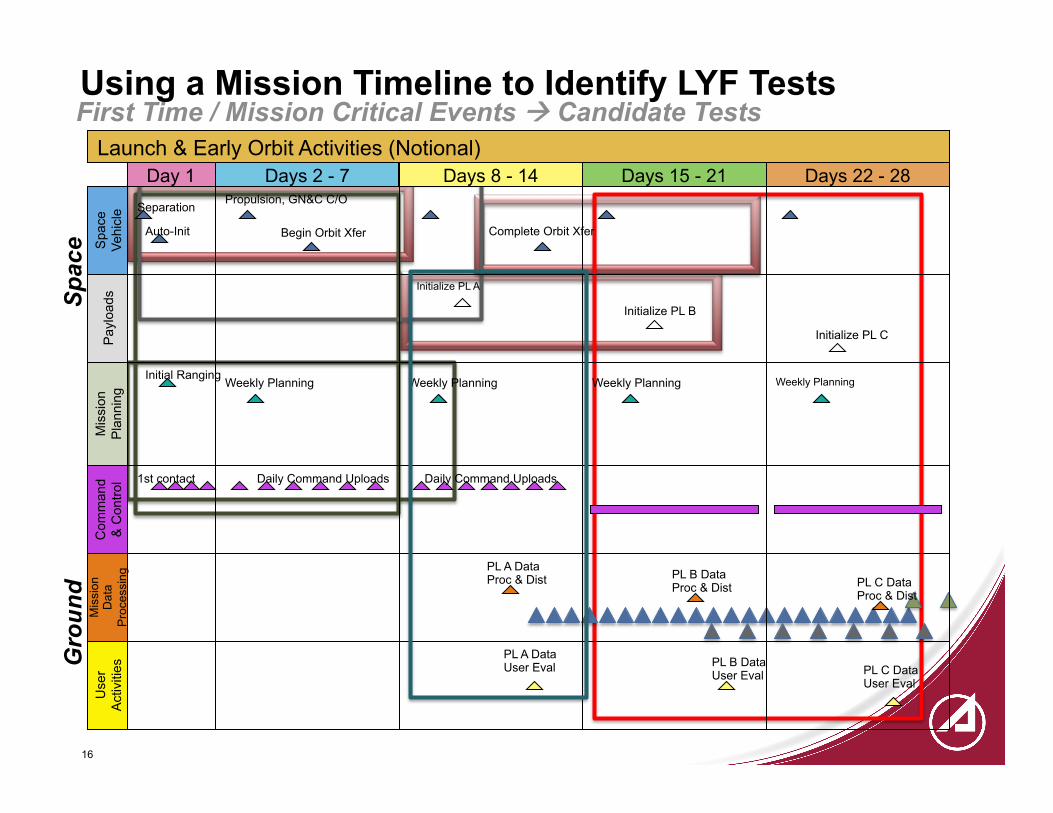
Using a Mission Timeline to Identify LYF Tests First Time / Mission Critical Events à Candidate Tests
Gro
und
Spa
ce
Launch & Early Orbit Activities (Notional)
Daily Command Uploads
PL A Data Proc & Dist
Auto-Init
Spa
ce
Vehi
cle
Pay
load
s M
issi
on
Pla
nnin
g C
omm
and
& C
ontro
l
Mis
sion
D
ata
Pro
cess
ing
Use
r A
ctiv
ities
Day 1 Days 8 - 14 Days 15 - 21 Days 22 - 28 Separation
1st contact
Initial Ranging
Initialize PL A
Initialize PL B
Initialize PL C
Weekly Planning Weekly Planning Weekly Planning Weekly Planning
Begin Orbit Xfer
Propulsion, GN&C C/O
Days 2 - 7
Complete Orbit Xfer
PL B Data Proc & Dist PL C Data
Proc & Dist
PL A Data User Eval PL B Data
User Eval PL C Data User Eval
Daily Command Uploads

17
Ascent Phase - First Time & Mission Critical Events Example - Candidate Tests
• TOCT (Prelaunch – Separation) – SV + LV + Ground – Launch base or ambient factory
• Ascent (T+0 -> Separation) (1a) – SV + LV – Ambient factory and/or TVAC – Software testbed (risk reduction)
• Ascent (T+0 -> Separation) (1b) – SV + LV – EMC chamber or antenna range
• Ascent w/ switch to redundant SV computer (T+0 -> Separation) (1c) – SV + LV – Ambient factory and/or TVAC or – Software testbed
What Mission Objectives Are To Be Included?
Ascent (Space Vehicle) Timeline Critical Event
Prelaunch Configure spacecraft computer unit (SCU)
Database upload
SW patch upload
Initialize SV configuration for launch
Switch to internal power
T + 0 Launch signal for SCU timer
T + 613 sec Turn on SGLS transmitters
T + 3 hr 33 m Separation
Example Ascent Phase mission objective: Have a properly working SV able to transition to next phase
TOCT = Total Operations Chain Test

18
Assess and Allocate Candidate Tests Across and Up & Down Pyramids
Feasibility Practicality Perceptivity
Program Value
Operational & Test Resources
Integration Level

19
Allocate Ascent Candidate Tests Across Pyramids Ascent Phase Tests - Example
Ascent 1a, c
Ascent 1b Ascent 1a, c
Ascent 1b
20
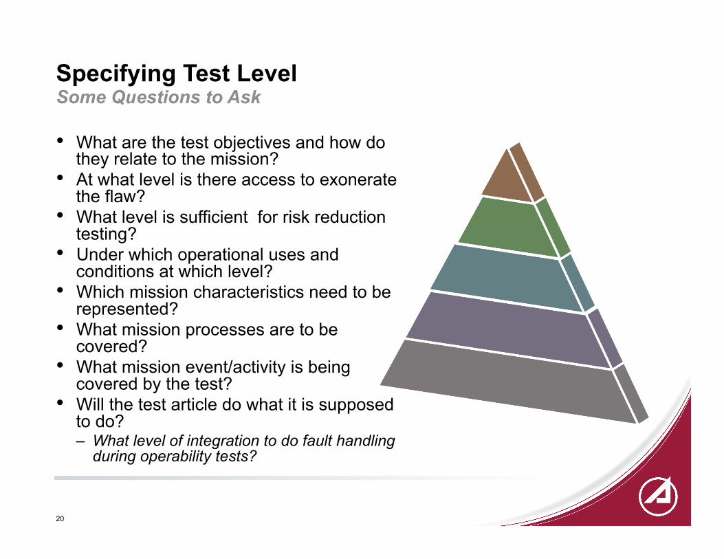
Specifying Test Level
• What are the test objectives and how do they relate to the mission?
• At what level is there access to exonerate the flaw?
• What level is sufficient for risk reduction testing?
• Under which operational uses and conditions at which level?
• Which mission characteristics need to be represented?
• What mission processes are to be covered?
• What mission event/activity is being covered by the test?
• Will the test article do what it is supposed to do? – What level of integration to do fault handling
during operability tests?
Some Questions to Ask
21
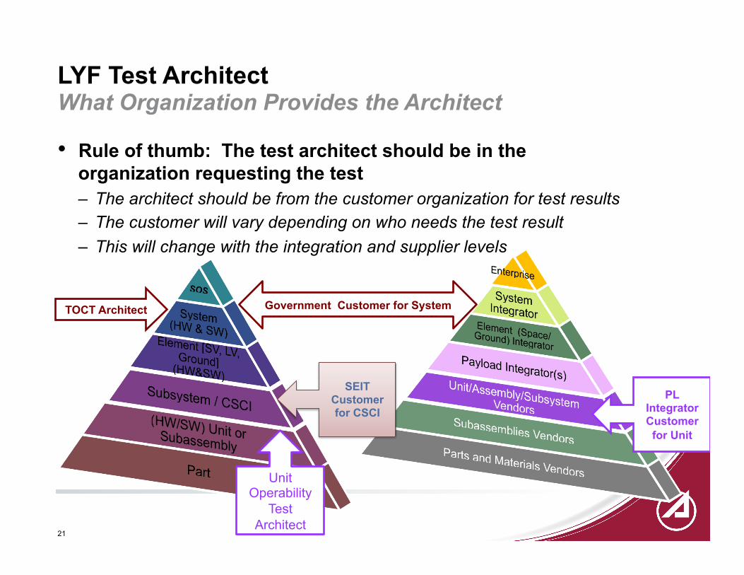
LYF Test Architect What Organization Provides the Architect
• Rule of thumb: The test architect should be in the organization requesting the test – The architect should be from the customer organization for test results – The customer will vary depending on who needs the test result – This will change with the integration and supplier levels
Government Customer for System TOCT Architect
PL Integrator Customer
for Unit
Unit Operability
Test Architect
SEIT Customer for CSCI

22
Days / Weeks in the Life: How Long Is Long Enough?
• Short Answer: Long enough to perform a representative timeline with all or most of the following: – Extent of vehicle operational requirements (e.g., 48
autonomous operations) – All necessary and mission critical first time events,
sequenced per flight and mission plans & constraints – Transitions, mode transitions, repetitive mission
activities, recurring events/situations – Core mission activities (e.g., EO observations, Comm
services) • Another Short Answer: Long enough to uncover
threats to mission: • Accumulated software & firmware error growth • Subtle trends • Generate sufficient data / transactions to
characterize occasional errors and out-of-family effects
• Memory leaks • Buffer overflows
Time-related Questions: • Initial condition
assumptions? • Continuous clocks? • Test duration? • Time jumps? • Compressed time? • Accelerated time? • Triggers?

23
Mission Characteristics Which Ones Are Critical to the Mission?
LYF Test
End-to-end (integration)
level
Configuration
Time & Timeline
Environments (Internal, Ascent, Space)
Commands
Telemetry (State of Health,
mission data)
Mission Planning & Operations
Products/ Outputs
Which ones are necessary for the test objectives?

24
Example: Design an Ascent Test Software Testbed (1c) • Test Cases
– Nominal: LV signal timing has range of rise time -> run 3 cases: slowest, average, fastest for each signal (T+0, sep)
– Off-nominal: Induce failover to redundant flight computer – Stressing: Do same test at beginning of TVAC (decreasing temperature & pressure)
• Initial conditions – SV configuration for launch; T+0
• Transition conditions – Ascent phase transition to auto-init phase
• End condition – T+4 hours; SV configured to acquire sun, orient antennas to earth
• Test design trades – Methods for inducing failover
• Flaw considerations – Flight computer has GIDEP re-timing sensitivity, so may need more timing cases – Hardware mis-install may lead to improper input to FSW
25
Summary
• FSW is the heart of most missions and most mission phases • The TLYF Process is meant to be flowed down to subsystems,
including flight software • Allocation of LYF tests to FSW testing should be done for risk
reduction prior to LYF tests of the flight vehicle • Allocation of LYF tests to FSW testing should be done because it is
– The most perceptive level to validate the execution of a significant number of flight processes
– The most perceptive level to discover a significant number of flight flaws – The most available setting to validate long duration mission activity
sequences – The most flexible setting for a large number of test cases – The safest setting for certain flight activities

26
Resources and References
• Shelton, D. and S. Roskie, Applying the Test Like You Fly Principle, 20th ATS, October 2001
• Beutelschies, Guy, Jet Propulsion Laboratory, Pasadena CA, “That One’s Gotta Work”: Mars Odyssey’s Use of a Fault Tree Driven Risk Assessment Process, IEEE 2001.
• White, J. D., Test Like You Fly: Assessment and Implementation Process, TOR-2010(8591)-6, January 2010
• Space Vehicle Test & Evaluation Handbook, Chapter 15, TOR-2011(8591)-2 Vol. 1
Published In Work
• White, J. D., Tilney, L. G., Test Like You Fly: Assessment & Implementation Process for Prelaunch Mission Testing, The Aerospace Corporation, TOR-2012(1315)-1