Embed Size (px)
Citation preview
ApproachestoModelingEthylbenzeneDehydrogenationinaRadialFlowReactorusingCOMSOLMultiphysics.
AMajorQualifyingProject
SubmittedtotheFacultyof
WorcesterPolytechnicInstitute
Inpartialfulfillmentoftherequirementsforthe
DegreeinBachelorofScienceIn
ChemicalEngineering
By:
__________________________________________
IanWaugh
Date:11/5/18
ProjectAdvisor:
___________________________
ProfessorAnthonyDixon
08Fall

1
Abstract:
Radial flow fixed bed reactors are used to carry out large-scale catalytic reactions.
Simulation of said reactors allows observation of effects of varying conditions in the
reactor. Using a 2D previously developed axisymmetric model in COMSOL, creation of
a more comprehensive model of the reactor was attempted. Ideally, inclusion of heat
transfer parameters and reaction kinetics would lead to a study of how varying physical
parameters in the reactor affect conversion of styrene in ethylbenzene dehydrogenation.
The paper addresses every approach taken using COMSOL to simulate said task and an
explanation of why said approaches failed. Furthermore, recommendations on how to
improve the model are listed.
2
Executive Summary:
A comprehensive simulation of a radial flow fixed bed reactor with inclusion of
specific reaction parameters in the catalyst bed would ensure a time-effective, low cost
way of determining effect of varying physical parameters in the reactor. Using, a
previously developed axisymmetric model in COMSOL, creation of a comprehensive
model of a reactor to carry out ethylbenzene dehydrogenation was attempted. This
executive summary lists the approaches taken when trying to complete said task.
Generation of accurate results was unsuccessful; therefore problems in the approaches
taken and recommendations for future attempts became the main focus of the report.
The main contributions of the previous project used as a basis were the conservation
of reactor geometry and of flow regimes. Turbulent flow parameters specified by the
previous group were maintained and inclusion of reaction kinetics and catalyst bed
specifications was attempted using the following modules in COMSOL:
• Heat Transfer in Porous Media: COMSOL uses Darcy-Brinkman correlations to
model flow through porous media. Ideally, this module would accurately model
heat transfer within the catalyst bed. Furthermore with specification of the catalyst
bed parameters and addition of a heat sink in the catalyst bed, heat transfer arising
from ethylbenzene dehydrogenation would accurately be modeled. This approach
was however discarded when coupling of three different modules in COMSOL
was not achieved. Boundary conditions between heat transfer module and heat
3
transfer in porous media could not be established, resulting in inconclusive results
and convergence errors
• Reaction Engineering Module: This was the most ambitious approach. If reaction
parameters and kinetics were established properly, then a conversion study with
actual species could be carried out. However due to little availability of intrinsic
kinetics for the reaction and inability to establish effective correlations within the
model, accurately specifying the reaction was a failure.
• Conjugate Heat Transfer: The problem with this module arose when trying to
specify the parameters for the bed. Conjugate heat transfer module couples
automatically both heat and turbulent flow equations. Resulting, in an ideal
approach, however modeling the bed was with the use of volume forces to specify
the resistance of the screens and within the bed. This approach did not converge,
not generating accurate results and debugging of the system was not achieved,
therefore the approach was unsuccessful.
As far as recommendations go, from observation and analysis of the failed
approaches, one should establish accurate intrinsic parameters and derive correlations in
order to achieve inclusion of them into COMSOL. However, this would be just the start
of the model and further problems may arise when defining the geometry and coupling
the reaction engineering module with the flow modules. Furthermore, one can attempt to
use a different platform, even though more labor intensive, a less interface defined

4
platform and a more merely mathematical one can allow more liberties and with proper
definition of the system of equations, modeling of conversion and how it’s affected based
on different variables can be analyzed from a mathematical point of view and
consequently a comprehensive study is generated.

5
Acknowledgements:
I would like to thank professor Anthony Dixon for allowing me to work with him
in his field of research and for his availability, guidance and willingness to help out with
any concerns throughout the project.
6
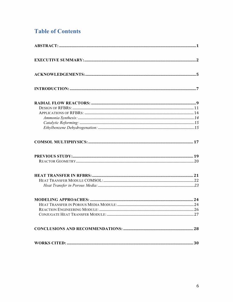
Table of Contents ABSTRACT:.............................................................................................................................................1
EXECUTIVE SUMMARY:...................................................................................................................2
ACKNOWLEDGEMENTS:..................................................................................................................5
INTRODUCTION:..................................................................................................................................7
RADIAL FLOW REACTORS:............................................................................................................9DESIGN OF RFBRS:.............................................................................................................................................11APPLICATIONS OF RFBRS:...............................................................................................................................14
Ammonia Synthesis:...........................................................................................................................................14Catalytic Reforming:.........................................................................................................................................15Ethylbenzene Dehydrogenation:...................................................................................................................15
COMSOL MULTIPHYSICS:............................................................................................................17
PREVIOUS STUDY:............................................................................................................................19REACTOR GEOMETRY.........................................................................................................................................20
HEAT TRANSFER IN RFBRS:........................................................................................................21HEAT TRANSFER MODULE COMSOL:.........................................................................................................22
Heat Transfer in Porous Media:...................................................................................................................23
MODELING APPROACHES:..........................................................................................................24HEAT TRANSFER IN POROUS MEDIA MODULE:.........................................................................................24REACTION ENGINEERING MODULE:..............................................................................................................26CONJUGATE HEAT TRANSFER MODULE:.....................................................................................................27
CONCLUSIONS AND RECOMMENDATIONS:........................................................................28
WORKS CITED:..................................................................................................................................30
7
Introduction:
Research and simulation of radial flow packed bed reactors is of dire importance
in the field of chemical engineering. These reactors allow certain catalytic reactions to be
carried out under more efficient and cost productive conditions than most commonly used
axial flow packed bed reactors. In a radial-flow reactor, the feed is distributed along the
length of the reactor, and flows in the radial direction across the catalyst bed contained
between two perforated concentric screens (Li, 2007). This configuration enables
operation at a lower pressure drop, which enables cost reduction as well as vessel size.
Flow maldistribution is one of the main issues present in radial flow reactors. A non-
uniform distribution of flow will cause an uneven distribution of catalyst usage inside the
bed. Consequently, leading to a less efficient reactor performance. Reactions such as
ammonia synthesis, methanol synthesis, catalytic reforming, and dehydrogenation of
ethylbenzene to styrene are all important, large scale catalytic reactions carried out with a
radial flow configuration (Li, 2007). The latter reaction will be addressed in this paper
Industrial styrene production is carried out mostly through the dehydrogenation of
ethylbenzene into styrene through a catalyst bed. This is an endothermic reaction favored
by operation at reduced pressure. In practice, steam is passed through with ethylbenzene
in order to reduce the partial pressure of the latter and ran through a packed bed with
selected catalysts, usually based on iron (III) oxide (Satterthwaite, 2017).
COMSOL Multiphysics is a general-purpose platform software for modeling
engineering applications. With it, simulating designs and processes based on
8
electromagnetics, structural mechanics, acoustics, fluid flow, heat transfer, and chemical
engineering behavior is possible. The program uses the finite element method to
approximate real solutions to partial differential equations with parameters defined by the
user (COMSOL, 2018). This platform was used to attempt, with the usage of different
modules and approaches, two different studies working towards the same purpose. First,
to generate a simulation of a radial flow reactor with pure component flow that included
heat transfer parameters to emulate the properties of a porous bed filled with iron (III)
oxide catalyst. This was attempted by using the heat transfer module in COMSOL.
Secondly, a more comprehensive approach was to design a model using the reaction-
engineering module to include the kinetics of ethylbenzene dehydrogenation catalyzed by
iron (III) oxide. Therefore, allowing analyzing how varying physical properties in the
reactor affect ethylbenzene conversion. Both studies were conducted in order to fulfill the
Major Qualifying Project (MQP) requirement under the supervision of Professor Anthony
Dixon.
This paper presents different approaches towards the modeling of a radial flow
reactor for ethylbenzene dehydrogenation. However, no satisfactory results were obtained
with any approach. Consequently, the paper explains what went wrong with every
approach and suggests how these problems could be solved if research is continued.
Both studies mentioned earlier were developed using a previous MQP submitted
to the faculty of Chemical Engineering at Worcester Polytechnic Institute (WPI) in 2014
9
as a basis. The reactor geometry and flow regimes used in the prior paper were
maintained.
Radial Flow Reactors:
In a fixed bed reactor, gas phase reactions are generally carried out using a
stationary bed of solid catalyst. In a typical reactor, suitable screens support the bed of
catalyst particles, through which the gas phase flows. Gaseous reactants adsorb on the
catalyst surface, reactions occur on this surface and reaction products desorb back to the
gas phase (Ranade, 2002). Two major types of fixed bed reactors are the conventional:
axial-flow and radial-flow. The latter type of flow is the one used in the reactor
simulation developed for this paper.
Radial-flow reactors were developed to replace axial-flow reactors for large-scale
chemical plants in the late 1960s and early 1970s. Radial-flow packed bed reactors are
different from axial flow reactors. In an axial-flow reactor the feed enters at one end of
the reactor, flows across the catalyst bed along the axis of the reactor and exits at the
other side (Li, 2007). On the other hand in a radial-flow reactor, the feed is distributed
along the length of the reactors and flows into and across the catalyst bed in a radial
fashion. RFBRs are essentially composed of three main parts aside from the inlet and
outlet: a center pipe, a catalyst bed with inner and outer perforated screens and an outer
annulus channel. Radial flow systems increase contact efficiency between the process
stream and catalyst bed. Because of this, vessel size can be dramatically reduced
(Johnson Screens, 2014). Feed can either be supplied through the outer annulus and flow
10
across the catalyst bed to the center pipe, resulting in what is known as centripetal flow.
Or, feed can be supplied to the center pipe and flow outwards resulting in centrifugal
flow. Additionally, In a Z-shaped radial-flow reactor, the feed and the effluent flow in the
same direction in the center pipe and the annulus and in a P-shaped reactor; the feed and
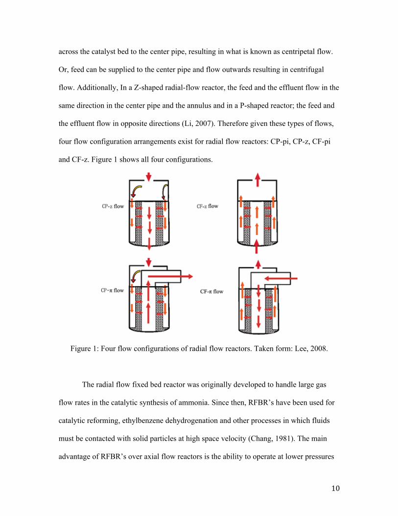
the effluent flow in opposite directions (Li, 2007). Therefore given these types of flows,
four flow configuration arrangements exist for radial flow reactors: CP-pi, CP-z, CF-pi
and CF-z. Figure 1 shows all four configurations.
Figure 1: Four flow configurations of radial flow reactors. Taken form: Lee, 2008.
The radial flow fixed bed reactor was originally developed to handle large gas
flow rates in the catalytic synthesis of ammonia. Since then, RFBR’s have been used for
catalytic reforming, ethylbenzene dehydrogenation and other processes in which fluids
must be contacted with solid particles at high space velocity (Chang, 1981). The main
advantage of RFBR’s over axial flow reactors is the ability to operate at lower pressures
11
or with a reduced pressure drop. Pressure drop plays an important role because a smaller
pressure drop allows reduction in catalyst particle size, which leads to increased
productivity and effectiveness. Additionally, it’s evidently safer to operate under a lower
pressure drop. The relatively large flow area offered by the inner or outer surface of the
catalyst basket decreases fluid velocity through the bed, thereby permitting the use of a
relatively short bed, which significantly reduces pressure drop (Chang, 1981).
Furthermore, as reactant is fed along the length of the reactor in RFBRs, a larger cross-
sectional area is available for the flow and the catalyst bed is shallower, thereby resulting
in a smaller pressure drop across the bed than in AFBRs.
A reduced pressure drop and a basket with radial flow simplify reactor scale up
significantly, which is a reason why radial flow is preferred in large-scale plants. As the
plant capacity increases, the diameter of an axial-flow reactor must be increased in order
to maintain the same pressure drop across the catalyst bed (Li, 2007). A vessel with a
very large diameter becomes heavy, impractical, expensive and of higher risk. At some
point, axial-flow reactors become impractically large so multiple reactors need to be
installed in parallel for process scale-up. On the other hand, increasing the length of the
catalyst bed scales RFBRs up, which is safer, cheaper and more practical than the
adjustments needed to scale up an AFBR.
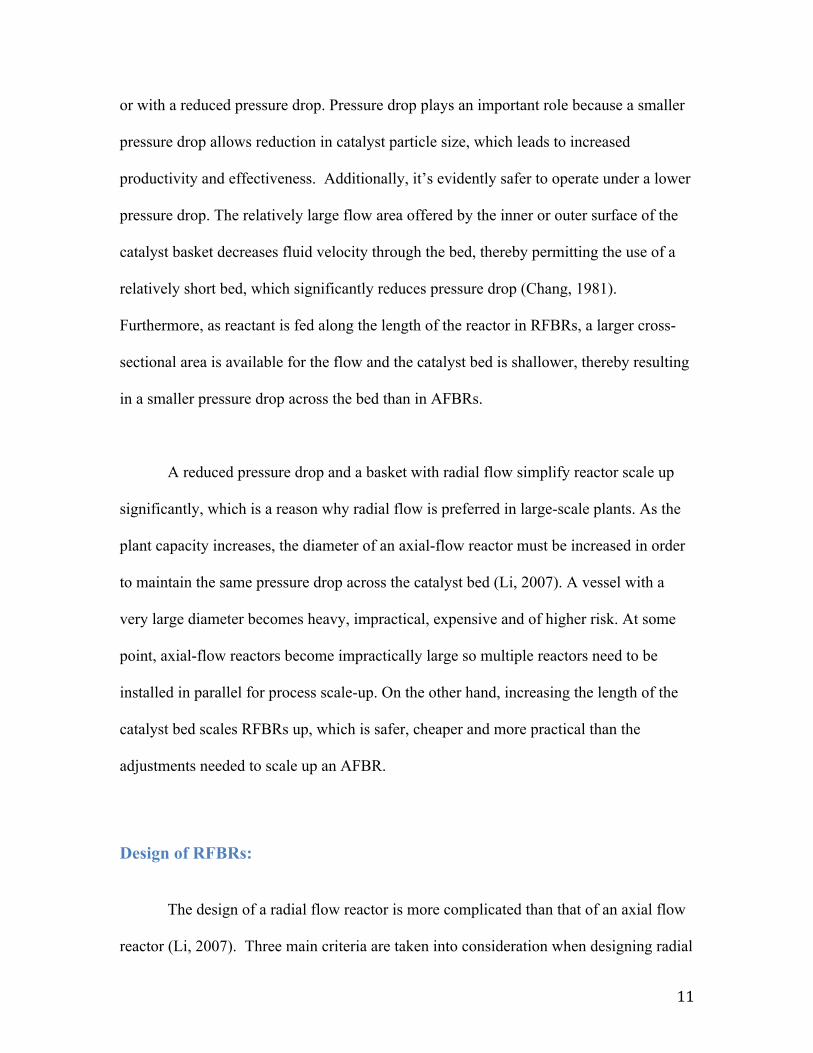
Design of RFBRs:
The design of a radial flow reactor is more complicated than that of an axial flow
reactor (Li, 2007). Three main criteria are taken into consideration when designing radial
12
flow reactors; flow distribution, catalyst settling and screen design. Furthermore, all of
these criteria are adjusted in order to achieve a flow as uniform as possible to ensure
maximum achievable effectiveness regarding the reactor’s performance.
Flow uniformity along the length of the bed ensures the catalyst is being used
evenly and therefore leads to higher conversion of reactant. If the flow is not evenly
distributed, some parts of the catalyst bed will be used more than others leading to faster
degeneration of the bed and bypass of flow eventually.
Catalyst settling occurs after continuous usage, where catalyst degeneration leads
to the formation of a void space in the bed. As the void space in the catalyst bed increases
so does flow bypassing and consequently flow maldistribution increases. The catalyst
settles as a result of the differential thermal expansion between the inner and outer
screens of the catalyst basket. In order to account for this phenomenon about 15 % extra
catalyst is normally loaded in a radial-flow reactor to allow for settling (Li, 2007).
Furthermore, this extra catalyst is loaded above the perforated section of the basket to
avoid bypassing at the top of the bed. The amount of catalyst needed for settling varies
from process to process, and is determined from practical experience and properties of
the materials used in the bed (Li, 2007).
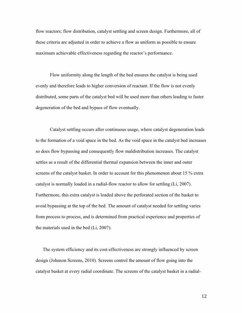
The system efficiency and its cost-effectiveness are strongly influenced by screen
design (Johnson Screens, 2010). Screens control the amount of flow going into the
catalyst basket at every radial coordinate. The screens of the catalyst basket in a radial-
13
flow reactor may be formed with perforated plates or V-shaped ‘‘wires’’ welded
circumferentially to supporting bars (Li, 2007). V-shaped wire screens are commonly
referred by the name of Johnson screens and they have been gradually replacing
perforated plates since the manufacture of large screens is inconvenient and expensive.
To provide elasticity for thermal expansion, a layer of wire mesh is sometimes overlaid
on the side of the perforated plate or the Johnson screen in contact with the catalyst (Li,
2007). Johnson screens provide a variety of benefits that enhance rector performance,
their main advantages are:
• Provide a stable screen/catalyst interface that reduces catalyst abrasion, enhancing
catalyst usage and durability.
• Vertical slots in the screens allow easier movement of the catalyst vertically,
reducing catalyst damage as well.
• Bed permeability remains high due to reduced catalyst abrasion, allowing for even
flow to be maintained.
• Strong screens provide resistance to high temperatures and pressure for a long
time, ensuring durability of the screen.
• Screen/catalyst interface does not become plugged which induces high pressure
drops, two-point contact with catalyst allows full movement of particles since
there is no slot entrapping of catalyst or catalyst particle pieces (Johnson Screens,
2010).
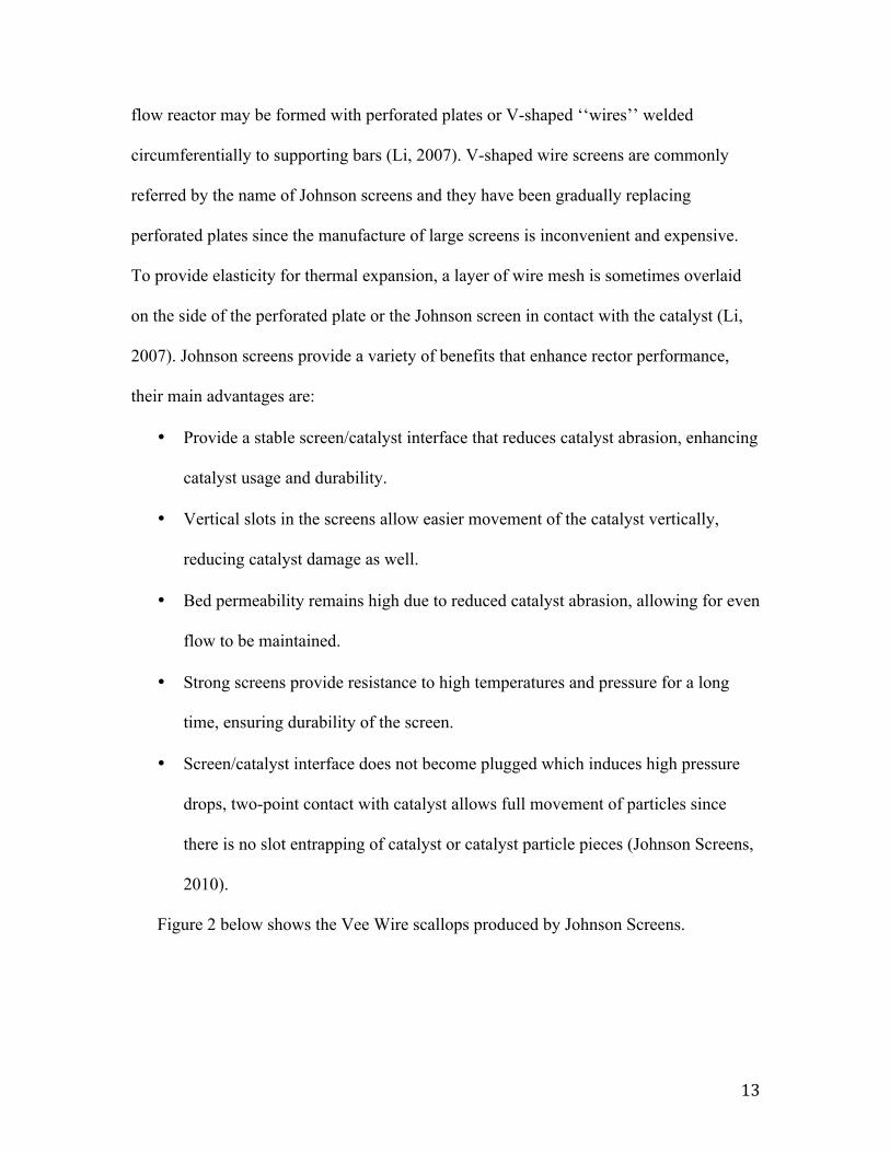
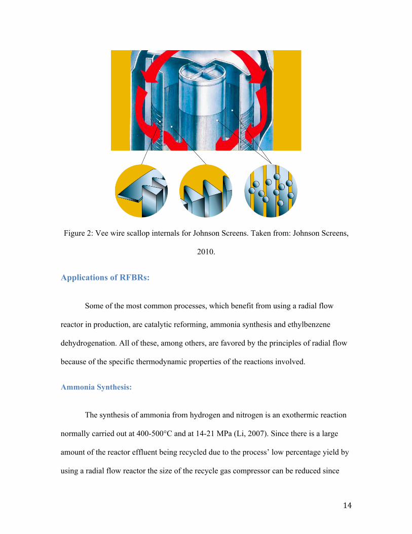
Figure 2 below shows the Vee Wire scallops produced by Johnson Screens.
14
Figure 2: Vee wire scallop internals for Johnson Screens. Taken from: Johnson Screens,
2010.
Applications of RFBRs:
Some of the most common processes, which benefit from using a radial flow
reactor in production, are catalytic reforming, ammonia synthesis and ethylbenzene
dehydrogenation. All of these, among others, are favored by the principles of radial flow
because of the specific thermodynamic properties of the reactions involved.
Ammonia Synthesis:
The synthesis of ammonia from hydrogen and nitrogen is an exothermic reaction
normally carried out at 400-500°C and at 14-21 MPa (Li, 2007). Since there is a large
amount of the reactor effluent being recycled due to the process’ low percentage yield by
using a radial flow reactor the size of the recycle gas compressor can be reduced since
15
said reactor operates at a lower pressure drop than an axial flow one. Furthermore smaller
catalyst pellets can be used, leading to increased catalyst efficiency (Li, 2007).
Catalytic Reforming:
Catalytic reforming is an important process in the petrochemical industry and is
used to increase octane number of naphtha in gasoline blending and in production of
benzene, toluene and xylenes (Li, 2007). This process consists of several reactions to
ultimately rearrange the molecules reacting. The overall effect of the reactions is
endothermic and they are carried out at a temperature range of 430-540°C. Thanks to new
more stable catalysts, reformers can operate at 700 kPa. Radial flow reactors are useful to
reduce pressure drop and thus the size of the recycle stream compressor (Li, 2007).
Ethylbenzene Dehydrogenation:
The dehydrogenation of ethylbenzene to styrene is an endothermic reaction that is
carried out with steam dilution at a temperature range of 540-650°C and under low
pressure or vacuum. Since the reaction is limited by thermodynamic equilibrium, both the
selectivity and conversion are favored by low-pressure conditions, therefore favoring the
use of a RFBR for this process (Li, 2007).
For commercial styrene production, in practice, steam is passed through with
ethylbenzene in order to reduce the partial pressure of the latter and ran through a packed
bed with selected catalysts, usually based on iron (III) oxide promoted by potassium
(Satterthwaite, 2017). Given that this is the process that was attempted to model, it’s
worth going into further explanation of the kinetics and thermodynamic properties of the
16
reaction. Benzene, toluene, methane and ethylene are the main by products in the
reaction. The whole system is fairly complex and experiments to determine intrinsic
kinetics are fairly limited (Lee, 2008). Few papers in literature actually address the
intrinsic kinetics in the system, most of them address experiment setups to determine
effective kinetics of the reactions occurring inside the catalyst bed (Lee, 2008). Based on
Lee’s paper “Ethylbenzene Dehydrogenation into Styrene: Kinetic Modeling and Reactor
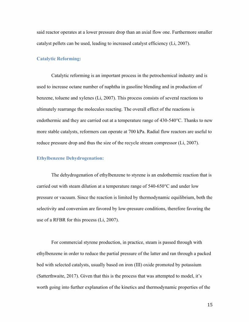
Simulation”, in ethylbenzene dehydrogenation four catalytic reactions occur. The
following diagram obtained from Lee’s paper illustrates the catalytic reaction scheme:
Figure 3: Catalytic Reaction Scheme for EB dehydrogenation. Taken from: Lee, 2008.
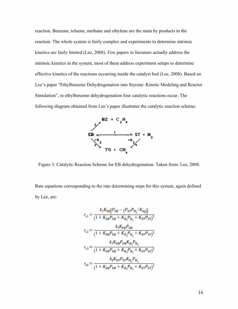
Rate equations corresponding to the rate determining steps for this system, again defined
by Lee, are:
17
Figure 4: Rate Equations for Catalytic Reactions. Taken from: Lee, 2008.
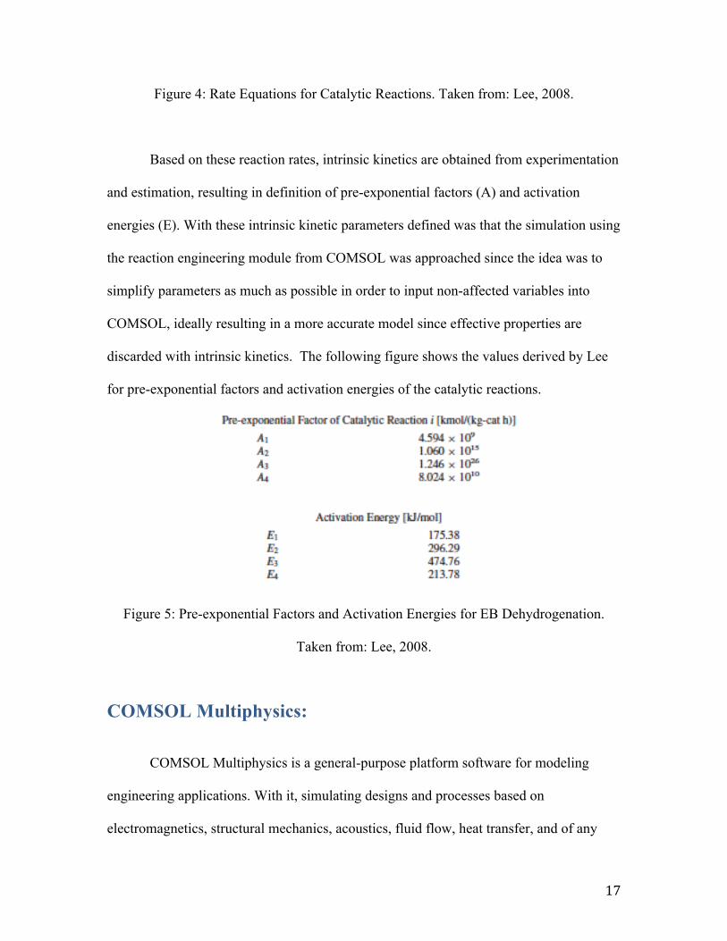
Based on these reaction rates, intrinsic kinetics are obtained from experimentation
and estimation, resulting in definition of pre-exponential factors (A) and activation
energies (E). With these intrinsic kinetic parameters defined was that the simulation using
the reaction engineering module from COMSOL was approached since the idea was to
simplify parameters as much as possible in order to input non-affected variables into
COMSOL, ideally resulting in a more accurate model since effective properties are
discarded with intrinsic kinetics. The following figure shows the values derived by Lee
for pre-exponential factors and activation energies of the catalytic reactions.
Figure 5: Pre-exponential Factors and Activation Energies for EB Dehydrogenation.
Taken from: Lee, 2008.
COMSOL Multiphysics:
COMSOL Multiphysics is a general-purpose platform software for modeling
engineering applications. With it, simulating designs and processes based on
electromagnetics, structural mechanics, acoustics, fluid flow, heat transfer, and of any
18
engineering behavior is possible. The program uses the finite element method to
approximate real solutions to partial differential equations with parameters defined by the
user (COMSOL, 2018). COMSOL was selected as the platform to develop the simulation
addressed in this paper since by using its CFD module it allows the coupling of different
physic parameters in the same model. Specifically the viability to couple flow regimes,
heat transfer profiles and reaction parameters is beneficial for this project.
In order to generate a COMSOL model, there are a variety of considerations that must
be taken into account to generate a working model. A generalized approach to developing
a COMSOL simulation as the one addressed in this paper is the following:
• Select description of flow based on operating parameters. Flow can be turbulent
or laminar and single-phase or two-phase.
• Generation of the model’s geometry. Either in 1D, 2D or 3D. In the case of this
study a 2D geometry was defined and interpreted as a 3D reactor by revolving the
geometry around its axial symmetry.
• Definition of fluid properties.
• Definition of heat transfer properties.
• Definition of reaction specifications.
• Addition of source and sink terms.
• Editing of governing equations if needed. Interphase and boundary condition
verification and compatibility. In order to generate an accurate study and allow
COMSOL to approach a solution considering all defined modules.
• Mesh definition.
19
• Tuning of desired solvers for generation of results.
Previous Study:
As stated, the simulation addressed in this paper was a continuation of a previous
study from 2014 submitted as a major qualifying project at Worcester Polytechnic
Institute under the sponsorship of a leading petrochemical company that contracted the
research development to Cambridge Chemical Technologies Inc. (Polcari, 2014). In the
previous study, pure component flow was simulated in a company-designed reactor.
Reactions occurring in the catalyst bed were ignored and the sponsors provided pressure
drop, flow rate and other specifications. The team analyzed flow maldistribution by
generation of flow profiles in COMSOL, and varied reactor parameters to illustrate how
these affect uniformity in distribution of flow. A maldistribution index was defined using
the average radial velocity at the radius being studied to define how uniform the flow
was. This allowed the maldistribution index to be the area between the average radial
velocity and the radial velocity profile at whatever radial coordinate was being studied
(Polcari, 2014). Based on this defined index; resistance in screens, catalyst particle size,
direction of flow and amount of total flow were all varied to define an optimum set of
variables that would lead to the most uniform flow distribution.
For the simulation addressed in this paper, the base case of the simulation was edited to
add heat transfer parameters. The base case had normal flow; no varying screen
resistance and flow in the reactor had a z-configuration with an inlet above the outer
annulus and an outlet at the base of the vessel. Moreover, the flow was defined using the
20
turbulent flow module in COMSOL and screen resistance was defined by addition of
three volume force terms to the outer and inner screen regions.
Reactor Geometry
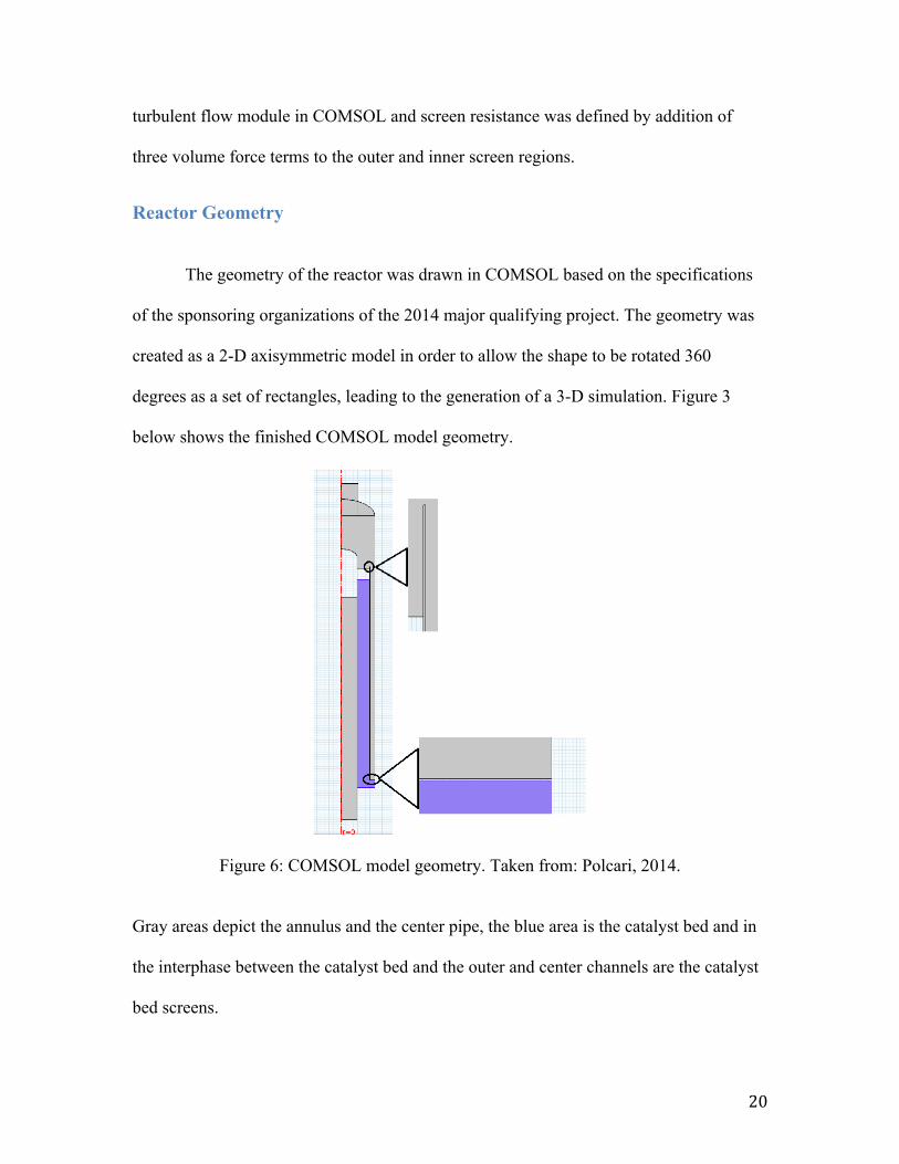
The geometry of the reactor was drawn in COMSOL based on the specifications
of the sponsoring organizations of the 2014 major qualifying project. The geometry was
created as a 2-D axisymmetric model in order to allow the shape to be rotated 360
degrees as a set of rectangles, leading to the generation of a 3-D simulation. Figure 3
below shows the finished COMSOL model geometry.
Figure 6: COMSOL model geometry. Taken from: Polcari, 2014.
Gray areas depict the annulus and the center pipe, the blue area is the catalyst bed and in
the interphase between the catalyst bed and the outer and center channels are the catalyst
bed screens.
21
Heat Transfer in RFBRs:
In an attempt to generate a more comprehensive reactor synapsis, heat transfer
modules were added to the model. Furthermore, since the model runs on pure component
flow and the reaction in the catalyst bed is not specified based on components, a heat sink
was added to the bed to generate heat transfer analysis. Heat transfer profiles in radial
flow reactor simulations are important to understand to a further extent how the reactor
will behave during operation. Reactions will always either generate or consume heat and
it is important to accurately specify heat transfer properties. By coupling heat transfer
properties with flow regimes one can then generate an interpretation of how temperature
will change at different parts of the bed, and therefore interpret how conversion, catalyst
utilization, and flow distribution are affected by the distribution of temperature inside the
bed. Furthermore, of special importance is the transport of energy in the radial direction,
as this is the means of heating or cooling the reactor. (Dixon, 2012). With well generated
coupled heat and flow profiles plus accurate specifications of the reaction occurring
inside the bed, one can create a full reactor synapsis that would not only predict
conversion and catalyst utilization at different scenarios manipulating different variables,
but would also help understand the reactor’s threshold in temperature and pressure. By
understanding the reactor vessel properties and by observation of temperature profiles
and flow regime one can depict the limits for safe operation of the process. Obviously,
this poses a great advantage in the field, since simulations are cheaper, safer and faster to
test with varying conditions than actually building the project for testing of variables.
Heat transfer in a fixed bed of particles takes place by:
22
• Conduction through the fluid.
• Conduction through the particles and from particle to particle through contact
points and stagnant fillets of gas around the contact points.
• Radiant heat transfer from particle to particle and from interparticle void to
interparticle void.
• Convective transport of energy by the fluid being displaced around the particles
as it flows through the bed.
• Particle-to-fluid heat transfer through the surrounding film
• Additionally, at the tube wall, there will be conduction through wall–particle
contacts, and transfer from the wall to the fluid (Dixon, 2012).
Heat Transfer Module COMSOL:
The heat transfer modeling software in COMSOL Multiphysics allows you to
analyze heat transfer by conduction, convection and radiation. With a set of features for
investigating thermal designs and effects of heat loads, modeling temperature fields,
profiles and heat fluxes throughout any geometry is possible (COMSOL, 2018).
Furthermore, the platform allows coupling of multiple physical effects in one simulation
with its multiphysics capabilities. This coupling is perhaps the most important fact in
what makes COMSOL an adequate program for the model addressed in this paper since it
allows coupling of flow regimes with heat transfer profiles and ideally in further research
would also allow inclusion of reaction kinetics into the model. Within the heat transfer
module in COMSOL, different types of heat transfer modes can be used depending on the
nature of the study being addressed. These are: heat transfer in solids, heat transfer in
23
fluids, local thermal non-equilibrium, heat transfer in porous media, bioheat transfer, heat
and moisture transport, thin structures, conjugate heat transfer, radiation and
electromagnetic heating.
Due to the nature of the study addressed in this paper and since the simulation is a
pure component flow reactor with a catalyst bed ideally packed with spherical catalyst
pellets, it seemed appropriate to add both heat transfer in fluids and heat transfer in
porous media to simulate the model.
Heat Transfer in Porous Media:
This module accounts for both conduction and convection in solid and open pore
phases of the porous matrix. You can select different averaging models to define effective
heat transfer properties that are calculated from the respective properties of the solid and
fluid materials (COMSOL, 2018). This module uses Darcy’s law alongside the Brinkman
equation to solve for porous media flow. Darcy’s law is defined as:
𝑞 = −𝑘𝜇 𝛻𝑝
Darcy’s law describes the rate at which a fluid flows through a permeable
membrane and in this case is used to model. It states that the flux (q) is defined by the
permeability (k) divided by the viscosity (𝜇) and multiplied by a pressure gradient vector
(∇𝑝) (COMSOL, 2018). With incorporation of the Brinkman form the equation becomes:
−𝛽𝛥!𝑞 + 𝑞 = −𝑘𝜇 𝛻𝑝
24
Where β is the effective viscosity term that accounts for flow through porous media.
Heat transfer in fluids through a free channel flow is modeled by the Navier-
Stokes equation defined by COMSOL as:
𝜌𝐶!𝑢𝛻𝑇 + 𝛻𝑞 = 𝑄 + 𝑄! + 𝑄!"
𝑞 = −𝑘𝛻𝑇
Modeling Approaches:
Heat Transfer in Porous Media Module:
Initially, in order to simulate the catalyst bed, the heat transfer in porous media
was chosen to approach the addition of heat transfer to the model. However, various
problems arose form the inclusion of this module. In the reactor being simulated, fluid
flow through the annulus channel and the center pipe, would be turbulent and ideally
modeled by the Navier-Stokes equation since it’s just fluid in a free flow channel.
However, when trying to couple both heat transfer defined by Navier-Stokes in the
annulus and center pipe and heat transfer in porous media defined by the Darcy-
Brinkman equation in the catalyst bed, boundary conditions between these two were not
able to be established. COMSOL is not able to couple both heat transfer modules
alongside turbulent flow and therefore no satisfying results were achieved. Thermal
insulation in the interphase between both heat transfer modules could not be removed,
25
neither could accurate boundary conditions be established. Failure to couple all three
modules together resulted in a need for a different approach.
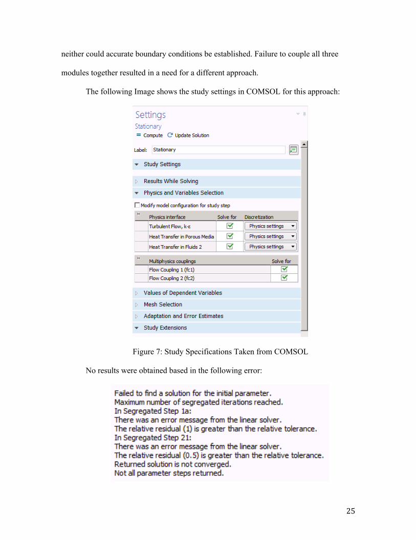
The following Image shows the study settings in COMSOL for this approach:
Figure 7: Study Specifications Taken from COMSOL
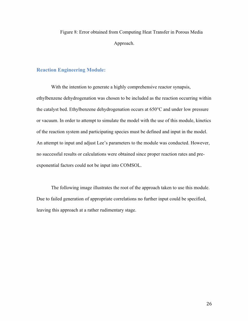
No results were obtained based in the following error:
26
Figure 8: Error obtained from Computing Heat Transfer in Porous Media
Approach.
Reaction Engineering Module:
With the intention to generate a highly comprehensive reactor synapsis,
ethylbenzene dehydrogenation was chosen to be included as the reaction occurring within
the catalyst bed. Ethylbenzene dehydrogenation occurs at 650°C and under low pressure
or vacuum. In order to attempt to simulate the model with the use of this module, kinetics
of the reaction system and participating species must be defined and input in the model.
An attempt to input and adjust Lee’s parameters to the module was conducted. However,
no successful results or calculations were obtained since proper reaction rates and pre-
exponential factors could not be input into COMSOL.
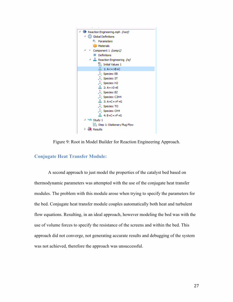
The following image illustrates the root of the approach taken to use this module.
Due to failed generation of appropriate correlations no further input could be specified,
leaving this approach at a rather rudimentary stage.
27
Figure 9: Root in Model Builder for Reaction Engineering Approach.
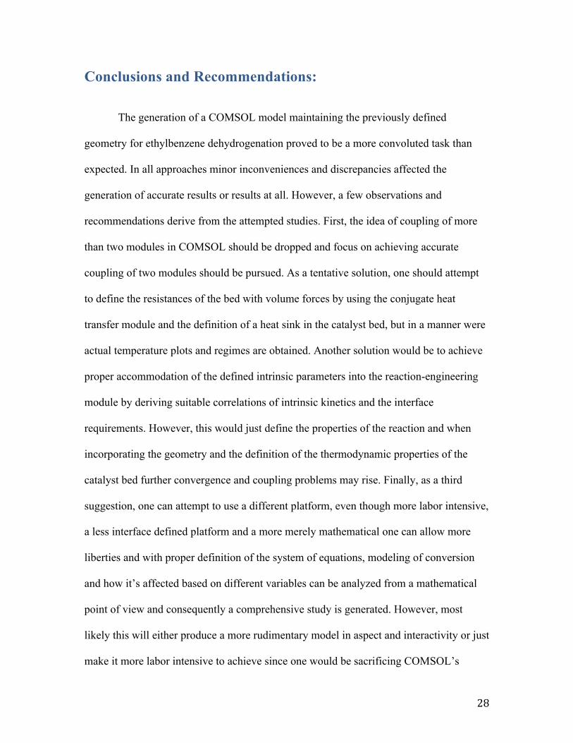
Conjugate Heat Transfer Module:
A second approach to just model the properties of the catalyst bed based on
thermodynamic parameters was attempted with the use of the conjugate heat transfer
modules. The problem with this module arose when trying to specify the parameters for
the bed. Conjugate heat transfer module couples automatically both heat and turbulent
flow equations. Resulting, in an ideal approach, however modeling the bed was with the
use of volume forces to specify the resistance of the screens and within the bed. This
approach did not converge, not generating accurate results and debugging of the system
was not achieved, therefore the approach was unsuccessful.
28
Conclusions and Recommendations:
The generation of a COMSOL model maintaining the previously defined
geometry for ethylbenzene dehydrogenation proved to be a more convoluted task than
expected. In all approaches minor inconveniences and discrepancies affected the
generation of accurate results or results at all. However, a few observations and
recommendations derive from the attempted studies. First, the idea of coupling of more
than two modules in COMSOL should be dropped and focus on achieving accurate
coupling of two modules should be pursued. As a tentative solution, one should attempt
to define the resistances of the bed with volume forces by using the conjugate heat
transfer module and the definition of a heat sink in the catalyst bed, but in a manner were
actual temperature plots and regimes are obtained. Another solution would be to achieve
proper accommodation of the defined intrinsic parameters into the reaction-engineering
module by deriving suitable correlations of intrinsic kinetics and the interface
requirements. However, this would just define the properties of the reaction and when
incorporating the geometry and the definition of the thermodynamic properties of the
catalyst bed further convergence and coupling problems may rise. Finally, as a third
suggestion, one can attempt to use a different platform, even though more labor intensive,
a less interface defined platform and a more merely mathematical one can allow more
liberties and with proper definition of the system of equations, modeling of conversion
and how it’s affected based on different variables can be analyzed from a mathematical
point of view and consequently a comprehensive study is generated. However, most
likely this will either produce a more rudimentary model in aspect and interactivity or just
make it more labor intensive to achieve since one would be sacrificing COMSOL’s

29
convenient preset capabilities to generate a more accurate, time consuming, and
computing intensive model.
30
Works Cited: Abdalla,a.(1994).Catalyticdehydrogenationofethylbenzenetostyreneinmembranereactors.AIChEJournal,40(12),2055–2059.Becker,i.(1993).Modellingofethylbenzenedehydrogenationinacatalyticmembranereactor.JournalofMembraneScience.,77(2-3),233–244.Carra,e,&Forni,u.(1965).KineticsofCatalyticDehydrogenationofEthylbenzenetoStyrene.Industrial&EngineeringChemistryProcessDesignandDevelopment.,4(3),281–285.Chang,s.(1983).Designcriterionforradialflowfixed-bedreactors.AIChEJournal,29(6),1039–1041.Chang,S.,&Calo,O.(1981).AnAnalysisofRadialFlowPackedBedReactors(Vol.168,pp.305–329).COMSOL(2018).Products.(n.d.).Retrievedfromhttps://www.comsol.com/Degannes,e.(1979).Theoxidativedehydrogenationofethylbenzenetostyrene.TheCanadianJournalofChemicalEngineering,57(5),627–630.Dixon,n.(2012).Fixedbedcatalyticreactormodelling-theradialheattransferproblem.TheCanadianJournalofChemicalEngineering,90(3),507–527.Elnashaie,a,Abdalla,a,&Hughes,o.(1993).Simulationoftheindustrialfixedbedcatalyticreactorforthedehydrogenationofethylbenzenetostyrene:heterogeneousdustygasmodel.Industrial&EngineeringChemistryResearch.,32(11),2537–2541.JohnsonScreens.(2010).Internalsforradialflowreactors.PDF.Retrieved:11/18.Kareeri,.,Zughbi,.,&Al-Ali,.(2006).SimulationofFlowDistributioninRadialFlowReactors.Industrial&EngineeringChemistryResearch.,45(8),2862–2874.Lee,o,&Froment,i.(2008).EthylbenzeneDehydrogenationintoStyrene:KineticModelingandReactorSimulation.Industrial&EngineeringChemistryResearch.,47(23),9183–9194.Li,J.C.(2007).Radial-FlowPacked-BedReactors.UllmannsEncyclopediaofIndustrialChemistry.doi:10.1002/14356007.l22_l01
31
Polcari,D.,Stolo,A.,&Tomida,M.(2014,December18).FlowAnalysisinaRadialFlowFixedBedReactor.Retrievedfromhttps://web.wpi.edu/Pubs/E-project/Available/E-project-121614-125138/unrestricted/Flow_Analysis_MQP.pdfRanade,V.V.(2002).Fixedbedandothertypesofreactors.Computationalflowmodelingforchemicalreactionengineeringvol.5(pp.403-423).SanDiego,CA:AcademicPress.Satterthwaite,e.(2017).PlasticsBasedonStyrene(pp.311–328).Savoretti,A.A.;Borio,D.O.;Bucala,V.;Porras,J.A.NonadiabaticRadial-flowReactorforStyreneProduction.Chem.Eng.Sci.1999,54,205–213.Sheppard,h,Maier,d,&Caram,u.(1986).Ethylbenzenedehydrogenationreactormodel.Industrial&EngineeringChemistryProcessDesignandDevelopment.,25(1),207–210.Sheppard,C.M.(1982).KineticandReactorModelfortheEthylbenzeneDehydrogenationReaction.M.S.thesis,LehighUniversity,Bethleham,PA.