Embed Size (px)
Citation preview
21 Motor Contactor J7KN
Motor Contactor
Main contactor
• AC & DC operated• Integrated auxiliary contacts• Screw fixing and snap fitting (35 mm DIN rail) up to 45 kWW
• Range from 4 to 110 kW (AC 3, 380/415V)• Finger proof ( VBG 4)
Accessoires
• front mounted single pole additional auxiliary contacts d single pole additional auxiliary contacts (1 NO or 1 NC)
• Side mounted additional auxiliary contacts (1 NO/1 NC)• Mechanical interlock• Suppressors (RC and varistor)
• Pneumatic timer modules• Link modules MPCB - Motor contactor
Approved StandardstandardsStandard Guide No (US,C)
UL NLDX, NLDX7
ICE 947-4-1
VDE 0660
EN 60947-4-1
22 Motor Contactor J7KN
Motor Contactor J7KN 23
Ordering Informationg Information
■ Model Number Legendber Legend1. Motor Contactors
1) Motor Contactor2) Rated Motor Current (AC3 400V)
10: 10A14: 14A18: 18A22: 22A24: 24A32: 32A40: 40A50: 50A62: 62A74: 74A85: 85A
110: 110A150: 150A175: 175A200: 200A
3) Integrated auxiliary contact10: 1NO 0NC01: 0NO 1NC21: 2NO 1NC22: 2NO 2NC
: 0NO 0NC4) Coil voltage ( AC operated )perated )
20: AC20V 50Hz, AC24V 60Hz24: AC24V 50/60Hz46: AC48V 50/60 Hz48: AC48V 50Hz, AC60V 60Hz
48B: AC48V 50Hz90: AC100V 50/60Hz
110: AC110V 50Hz, AC110-120V 60Hz 180: AC180-210V 50Hz, AC200-240V 60Hz230: AC220-240V 50Hz, AC240V 60Hz400: AC380-415V 50Hz, AC415-440V 60Hz500: AC500-550V 50Hz, AC550-600V 60Hz
Coil voltage( DC operated )24D: DC24V48D: DC48V
110D: DC110V125D: DC125V
2. Aux. Contact Modules for Motor Contactors
1) Auxiliary Contact Modules 2) B: for motor contactor (4-37kW)W)
C: for motor contactor (11-37kW)3) Combination of NO/NC contacts
10: 1NO 0NC01: 0NO 1NC11: 1NO 1NC
4) S: side mounting: front mounting
3. Accessories for Motor Contactors(Link Modules MPCB - Motor Contactor)
1) Accessories for Motor Contactors 2) VD: Link module type
HU:U: DIN-rail adapter type3) 12: for motor contactor (4 - 7.5kW)
25: for motor contactor (11 - 15kW)
4. Accessories for Motor Contactors(Pneumatic Timers)
1) Accessories for Motor Contactors2) B: Motor Contactor (4-11kW)3) TP: Pneumatic Timer4) 40: 40 sec
180: 180 sec5) DA: ON-delayed
IA: OFF-delayed
5. Accessories for Motor Contactors (Mechanical Interlock)
1) Accessories for Motor Contactors2) B: Motor Contactor (4-18.5kW)
C: Motor Contactor (22-37kW)D: Motor Contactor (45-55kW)
3) ML: Mechanical Interlock
6. Accessories for Motor Contactors (RC Suppressor units)ppressor units)
1) Accessories for Motor Contactors2) A: for Mini Motor Contactor and Motor Contactor
(4-18.5kW)(between DIN-rail and Contactor)
B: for Mini Motor Contactor and Motor Contactor (4-55kW)(universal)
3) RC: RC-surge suppressors4) 48: 24 - 48 VAC/DC
230: 110 - 230 VAC/DC400: 250 - 415 VAC/DC
7. Accessories for Motor Contactors (Varistor units)
1) Accessories for Motor Contactors2) A: for Motor Contactor (4-11kW) to snap on
to coil terminalsB: for Motor Contactor (4-37kW) to snap on to contactor
3) VG: Varistor Suppressors4) 230: 110-230VAC/DC
400: 250-415VAC/DC
J7KN-###-##-####1 2 3 4
J73KN-#-##-#1 2 3 4
J74KN-##-##1 2 3
J74KN-#-## ### ##1 2 3 4 5
J74KN-#-##1 2 3
J74KN-#-## ###1 2 3 4
J74KN-#-## ###1 2 3 4
24 Motor Contactor J7KN
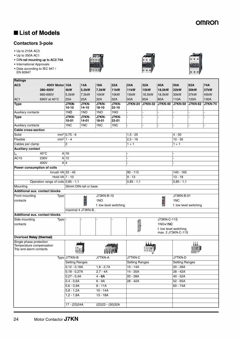
■ List of Modelst of Models
Contactors 3-pole
• Up to 210A AC3• Up to 350A AC1• DIN-rail mounting up to AC3 74AN-rail mounting up to AC3 74A• International Approvals• Data according to IEC 947 /
EN 60947
RatingsAC3 400V Motor 10A 14A 18A 22A 24A 32A 40A 50A 62A 74A
380-400V 4kW 5,5kW 7,5kW 11kW 11kW 15kW 18,5kW 22kW 30kW 37kW660-690V 5,5kW 7,5kW 10kW 10kW 15kW 18,5kW 18,5kW 30kW 37kW 45kW
AC1 690V at 40°C 25A 25A 32A 32A 50A 65A 80A 110A 120A 130A
Type J7KN-N-10-10
J7KN-14-10
J7KN-18-10
J7KN-22-10
J7KN-24 J7KN-32 J7KN-40 J7KN-50 J7KN-62 J7KN-74
Auxiliary contacts 1NOO 1NO 1NO 1NO - - - - - -
Type J7KN-10-01
J7KN-14-01
J7KN-18-01
J7KN-22-01
- - - - - -
Auxiliary contacts 1NC 1NC 1NC 1NC - - - - - -
Cable cross-sectionSolid mm2 0,75 - 6 1,5 - 25 4 - 50
Flexible mm2 1 - 4 2,5 - 16 10 - 35
Cables per clamp 2 1 + 1 1 + 1
Auxiliary contactIth 40°C A 16 - -
AC15 230V A 12 - -
400V A 4 - -
Power consumption of coilsInrush VA 33 - 45 90 - 115 140 - 165
Hold VA 7 - 10 9 - 13 13 - 18
Operation range of coils 0,85 - 1,1 0,85 - 1,1 0,85 - 1,1
Mounting 35mm DIN-rail or base
Additional aux. contact blocksFront mounting Type J73KN-B-10 J73KN-B-01
contacts 1NO 1NC
f. low level switching f. low level switching
maximal 4 J73KN-B..
Additional aux. contact blocksSide mounting Type - - - - J73KN-C-11S
contacts 1NO+1NC+1NC
f. low level switchingmax. 2 J73KN-C-11S
Overload Relay (thermal)Relay (thermal)Single phase protection Temperature compensation Trip and alarm contacts
Type J7TKN-B J7TKN-A J7TKN-C J7TKN-D
Setting Ranges Setting Ranges Setting Ranges
0,12 - 0,18A 1,8 - 2,7A 10 - 14A 20 - 28A
0,18 - 0,27A 2,7 - 4A 14 - 20A 28 - 42A
0,27 - 0,4A 4 - 6A6A 20 - 28A 40 - 52A
0,4 - 0,6A 6 - 9A 28 - 42A 52 - 65A
0,6 - 0,9A 8 - 11A 60 - 74A
0,8 - 1,2A 10 - 14A
1,2 - 1,8A 13 - 18A
17 - (23)24A (22)23 - (30)32A
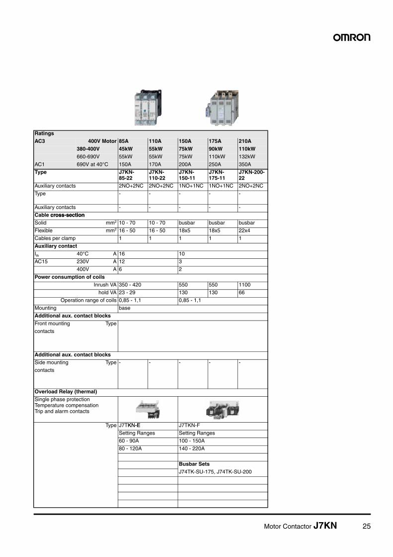
Motor Contactor J7KN 25
RatingsAC3 400V Motor 85A 110A 150A 175A 210A
380-400V 45kW 55kW 75kW 90kW 110kW660-690V 55kW 55kW 75kW 110kW 132kW
AC1 690V at 40°C 150A 170A 200A 250A 350A
Type J7KN-85-22
J7KN-110-22
J7KN-150-11
J7KN-175-11
J7KN-200-22
Auxiliary contacts 2NO+2NC 2NO+2NC 1NO+1NC 1NO+1NC 2NO+2NC
Type - - - - -
Auxiliary contacts - - - - -
Cable cross-sectioncross-sectionSolid mm2 10 - 70 10 - 70 busbar busbar busbar
Flexible mm2 16 - 50 16 - 50 18x5 18x5 22x4
Cables per clamp 1 1 1 1 1
Auxiliary contactIth 40°C A 16 10
AC15 230V A 12 3
400V A 6 2
Power consumption of coilsInrush VA 350 - 420 550 550 1100
hold VA 23 - 29 130 130 66
Operation range of coils 0,85 - 1,1 0,85 - 1,1
Mounting base
Additional aux. contact blocksFront mounting Type
contacts
Additional aux. contact blocksSide mounting Type - - - - -
contacts
Overload Relay (thermal)Single phase protection Temperature compensation Trip and alarm contacts
Type J7TKN-EKN-E J7TKN-F
Setting Ranges Setting Ranges
60 - 90A 100 - 150A
80 - 120A 140 - 220A
Busbar SetsJ74TK-SU-175, J74TK-SU-200
26 Motor Contactor J7KN
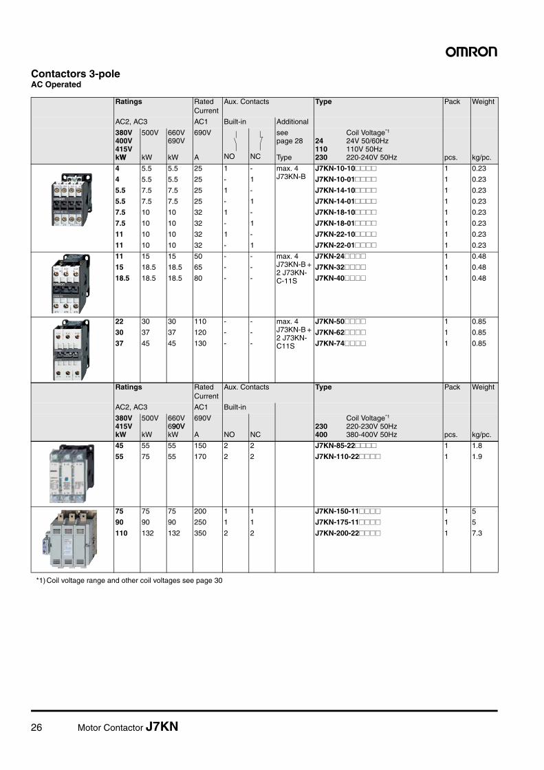
Contactors 3-poleAC Operated
Ratings Rated Current
Aux. Contacts Type Pack Weight
AC2, AC3 AC1 Built-in Additional
380V400V415VkWW
500V
kW
660V690V
kW
690V
A NO NC
seepage 28
Type
Coil Voltage*1
24 24V 50/60Hz110 110V 50Hz230 220-240V 50Hz
*1) Coil voltage range and other coil voltages see page 30
pcs. kg/pc.
4 5.5 5.5 25 1 - max. 4J73KN-B
J7KN-10-10#### 1 0.23
4 5.5 5.5 25 - 1 J7KN-10-01#### 1 0.23
5.5 7.5 7.5 25 1 - J7KN-14-10#### 1 0.23
5.5 7.5 7.5 25 - 1 J7KN-14-01#### 1 0.23
7.5 10 10 32 1 - J7KN-18-10#### 1 0.23
7.5 10 10 32 - 1 J7KN-18-01#### 1 0.23
11 10 10 32 1 - J7KN-22-10#### 1 0.23
11 10 10 32 - 1 J7KN-22-01#### 1 0.23
11 15 15 50 - - max. 4J73KN-B + 2 J73KN-C-11S
J7KN-24#### 1 0.48
15 18.5 18.5 65 - - J7KN-32#### 1 0.48
18.5 18.5 18.5 80 - - J7KN-40#### 1 0.48
22 30 30 110 - - max. 4J73KN-B + 2 J73KN-C11S
J7KN-50#### 1 0.85
30 37 37 120 - - J7KN-62#### 1 0.85
37 45 45 130 - - J7KN-74#### 1 0.85
Ratings Rated Current
Aux. Contacts Type Pack Weight
AC2, AC3 AC1 Built-in
380V415VkW
500V
kW
660V690V90VkW
690V
A NO NC
Coil Voltage*1
230 220-230V 50Hz400 380-400V 50Hz pcs. kg/pc.
45 55 55 150 2 2 J7KN-85-22#### 1 1.8
55 75 55 170 2 2 J7KN-110-22#### 1 1.9
75 75 75 200 1 1 J7KN-150-11#### 1 5
90 90 90 250 1 1 J7KN-175-11#### 1 5
110 132 132 350 2 2 J7KN-200-22#### 1 7.3
Motor Contactor J7KN 27
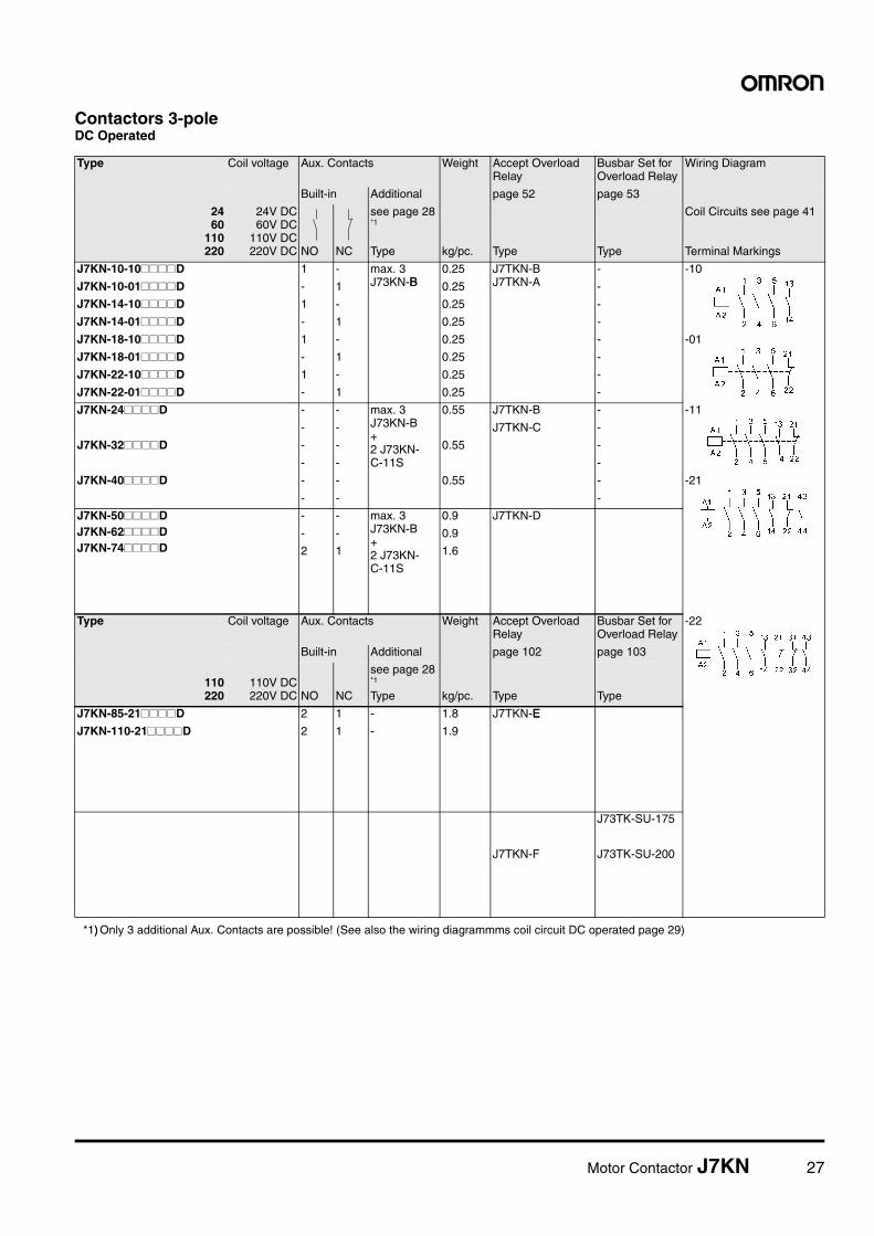
Contactors 3-poleDC Operated
Type Coil voltage Aux. Contacts Weight Accept Overload Relay
Busbar Set for Overload Relay
Wiring Diagram
Built-in Additional page 52 page 53
2460
110220
24V DC60V DC
110V DC220V DC NO NC
see page 28*1
Type
*1)) Only 3 additional Aux. Contacts are possible! (See also the wiring diagrammms coil circuit DC operated page 29)
kg/pc. Type Type
Coil Circuits see page 41
Terminal Markings
J7KN-10-10####D 1 - max. 3J73KN-BB
0.25 J7TKN-BJ7TKN-A
- -10
J7KN-10-01####D - 1 0.25 -
J7KN-14-10####D 1 - 0.25 -
J7KN-14-01####D - 1 0.25 -
J7KN-18-10####D 1 - 0.25 - -01
J7KN-18-01####D - 1 0.25 -
J7KN-22-10####D 1 - 0.25 -
J7KN-22-01####D - 1 0.25 -
J7KN-24####D - - max. 3J73KN-B+2 J73KN-C-11S
0.55 J7TKN-B - -11
- - J7TKN-C -
J7KN-32####D - - 0.55 -
- - -
J7KN-40####D - - 0.55 - -21
- - -
J7KN-50####DJ7KN-62####DJ7KN-74####D
- - max. 3J73KN-B+2 J73KN-C-11S
0.9 J7TKN-D
- - 0.9
2 1 1.6
Type Coil voltage Aux. Contacts Weight Accept Overload Relay
Busbar Set for Overload Relay
-22
Built-in Additional page 102 page 103
110220
110V DC220V DC NO NC
see page 28*1
Type kg/pc. Type Type
J7KN-85-21####D 2 1 - 1.8 J7TKN-EE
J7KN-110-21####D 2 1 - 1.9
J73TK-SU-175
J7TKN-F J73TK-SU-200
28 Motor Contactor J7KN
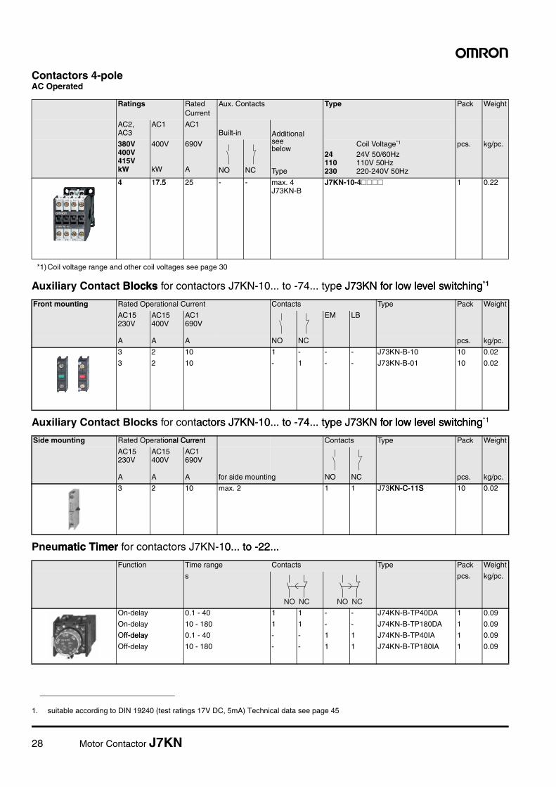
Contactors 4-poleAC Operated
Auxiliary Contact BlocksBlocks for contactors J7KN-10... to -74... type J73KN for low level switchinge J73KN for low level switching*1
Auxiliary Contact Blocks for contactors J7KN-10... to -74... type J73KN for low level switchingactors J7KN-10... to -74... type J73KN for low level switchingfor low level switching*1
Pneumatic Timer matic Timer for contactors J7KN-10... to -22...0... to -22...
Ratings Rated Current
Aux. Contacts Type Pack Weight
AC2, AC3
AC1 AC1Built-in Additional
seebelow
Type
380V400V415VkW
400V
kW
690V
A NO NC
Coil Voltage*1
24 24V 50/60Hz110 110V 50Hz230 220-240V 50Hz
*1) Coil voltage range and other coil voltages see page 30
pcs. kg/pc.
4 17.57.5 25 - - max. 4J73KN-B
J7KN-10-4#### 1 0.22
1. suitable according to DIN 19240 (test ratings 17V DC, 5mA) Technical data see page 45
Front mounting Rated Operational Current Contacts Type Pack Weight
AC15230V
AC15400V
AC1690V
EM LB
A A A NO NC pcs. kg/pc.
3 2 10 1 - - - J73KN-B-10 10 0.02
3 2 10 - 1 - - J73KN-B-01 10 0.02
Side mounting Rated Operational Currentonal Current Contacts Type Pack Weight
AC15230V
AC15400V
AC1690V
A A A for side mounting NO NC pcs. kg/pc.
3 2 10 max. 2 1 1 J73KN-C-11SKN-C-11S 10 0.02
Function Time range Contacts Type Pack Weight
s pcs. kg/pc.
On-delay 0.1 - 40 1 1 - - J74KN-B-TP40DA 1 0.09
On-delay 10 - 180 1 1 - - J74KN-B-TP180DA 1 0.09
Off-delayff-delay 0.1 - 40 - - 1 1 J74KN-B-TP40IA 1 0.09
Off-delay 10 - 180 - - 1 1 J74KN-B-TP180IA 1 0.09
NO NC NO NC
Motor Contactor J7KN 29
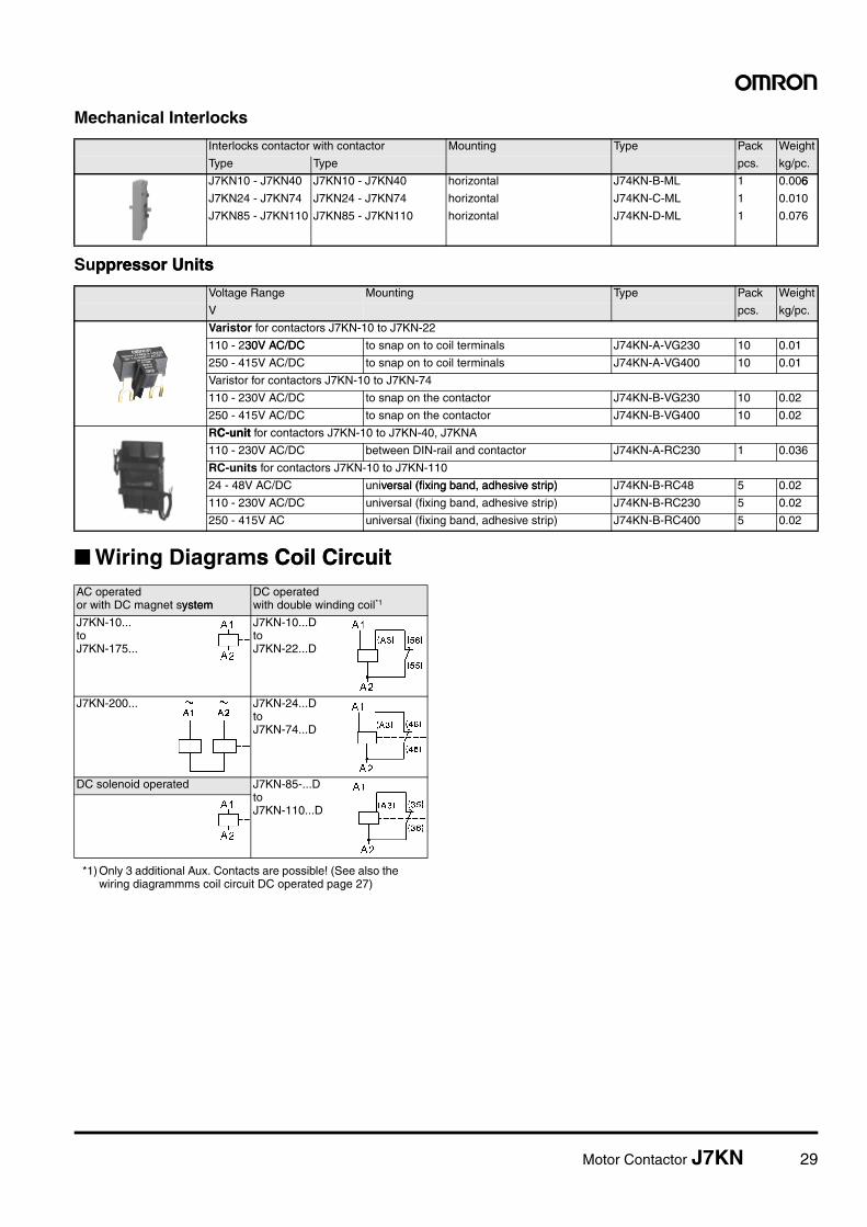
Mechanical Interlocks
Suppressor Unitsppressor Units
■ Wiring Diagrams Coil Circuits Coil Circuit
Interlocks contactor with contactor Mounting Type Pack Weight
Type Type pcs. kg/pc.
J7KN10 - J7KN40 J7KN10 - J7KN40 horizontal J74KN-B-ML 1 0.0066
J7KN24 - J7KN74 J7KN24 - J7KN74 horizontal J74KN-C-ML 1 0.010
J7KN85 - J7KN110 J7KN85 - J7KN110 horizontal J74KN-D-ML 1 0.076
Voltage Range Mounting Type Pack Weight
V pcs. kg/pc.
Varistor for contactors J7KN-10 to J7KN-22
110 - 230V AC/DC30V AC/DC to snap on to coil terminals J74KN-A-VG230 10 0.01
250 - 415V AC/DC to snap on to coil terminals J74KN-A-VG400 10 0.01
Varistor for contactors J7KN-10 to J7KN-74
110 - 230V AC/DC to snap on the contactor J74KN-B-VG230 10 0.02
250 - 415V AC/DC to snap on the contactor J74KN-B-VG400 10 0.02
RC-unitC-unit for contactors J7KN-10 to J7KN-40, J7KNA
110 - 230V AC/DC between DIN-rail and contactor J74KN-A-RC230 1 0.036
RC-units for contactors J7KN-10 to J7KN-110
24 - 48V AC/DC universal (fixing band, adhesive strip)versal (fixing band, adhesive strip) J74KN-B-RC48 5 0.02
110 - 230V AC/DC universal (fixing band, adhesive strip) J74KN-B-RC230 5 0.02
250 - 415V AC universal (fixing band, adhesive strip) J74KN-B-RC400 5 0.02
AC operatedor with DC magnet systemystem
DC operatedwith double winding coil*1
*1) Only 3 additional Aux. Contacts are possible! (See also the wiring diagrammms coil circuit DC operated page 27)
J7KN-10... to J7KN-175...
J7KN-10...D to J7KN-22...D
J7KN-200... J7KN-24...D to J7KN-74...D
DC solenoid operated J7KN-85-...D to J7KN-110...D
30 Motor Contactor J7KN
Specificationsns
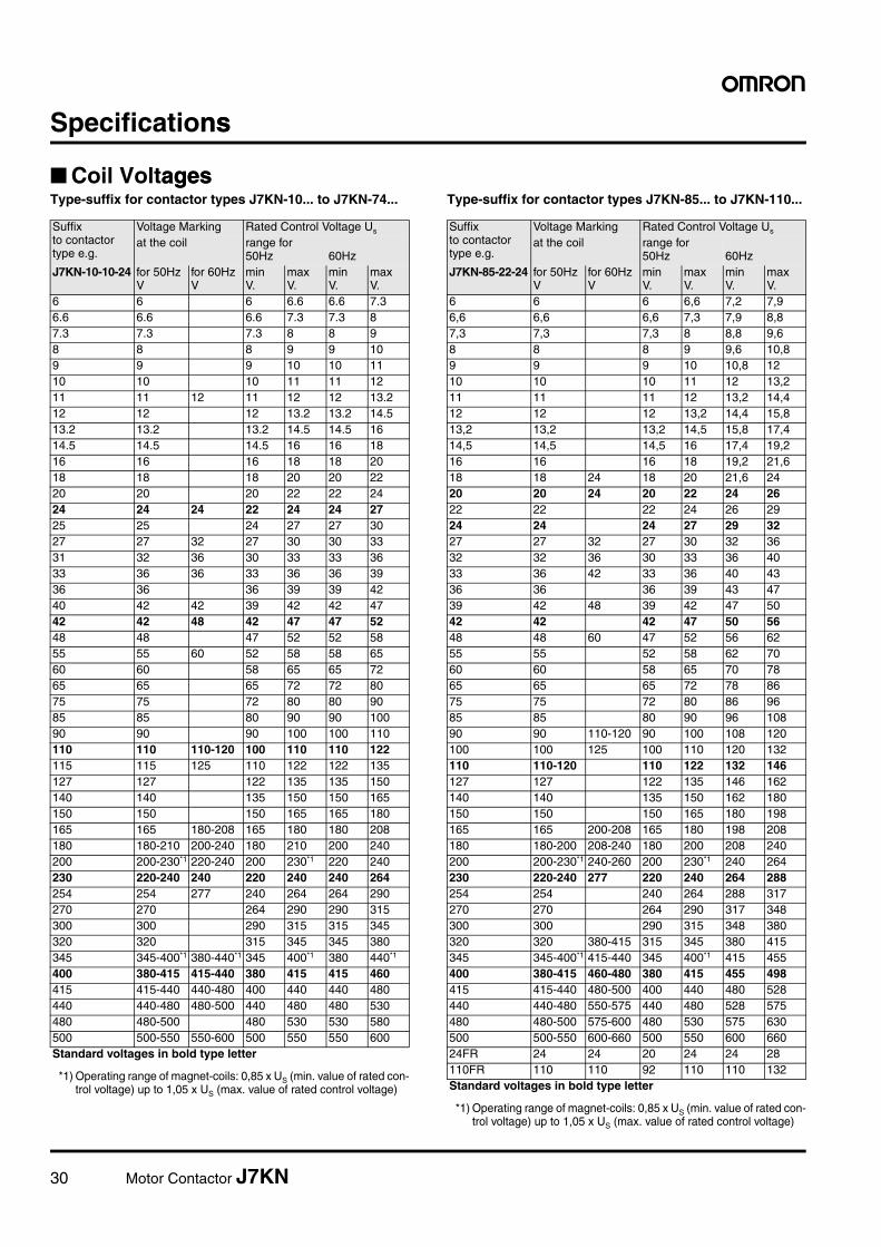
■ Coil VoltagesagesType-suffix for contactor types J7KN-10... to J7KN-74... Type-suffix for contactor types J7KN-85... to J7KN-110...
Suffixto contactor type e.g.
Voltage Marking Rated Control Voltage Us
at the coil range for 50Hz 60Hz
J7KN-10-10-24 for 50HzV
for 60HzV
min V.
max V.
min V.
max V.
6 6 6 6.6 6.6 7.36.6 6.6 6.6 7.3 7.3 87.3 7.3 7.3 8 8 98 8 8 9 9 109 9 9 10 10 1110 10 10 11 11 1211 11 12 11 12 12 13.212 12 12 13.2 13.2 14.513.2 13.2 13.2 14.5 14.5 1614.5 14.5 14.5 16 16 1816 16 16 18 18 2018 18 18 20 20 2220 20 20 22 22 2424 24 24 22 24 24 2725 25 24 27 27 3027 27 32 27 30 30 3331 32 36 30 33 33 3633 36 36 33 36 36 3936 36 36 39 39 4240 42 42 39 42 42 4742 42 48 42 47 47 5248 48 47 52 52 5855 55 60 52 58 58 6560 60 58 65 65 7265 65 65 72 72 8075 75 72 80 80 9085 85 80 90 90 10090 90 90 100 100 110110 110 110-120 100 110 110 122115 115 125 110 122 122 135127 127 122 135 135 150140 140 135 150 150 165150 150 150 165 165 180165 165 180-208 165 180 180 208180 180-210 200-240 180 210 200 240200 200-230*1
*1) Operating range of magnet-coils: 0,85 x US (min. value of rated con-trol voltage) up to 1,05 x US (max. value of rated control voltage)
220-240 200 230*1 220 240230 220-240 240 220 240 240 264254 254 277 240 264 264 290270 270 264 290 290 315300 300 290 315 315 345320 320 315 345 345 380345 345-400*1 380-440*1 345 400*1 380 440*1
400 380-415 415-440 380 415 415 460415 415-440 440-480 400 440 440 480440 440-480 480-500 440 480 480 530480 480-500 480 530 530 580500 500-550 550-600 500 550 550 600Standard voltages in bold type letter
Suffixto contactor type e.g.
Voltage Marking Rated Control Voltage Us
at the coil range for 50Hz 60Hz
J7KN-85-22-24 for 50HzV
for 60HzV
min V.
max V.
min V.
max V.
6 6 6 6,6 7,2 7,96,6 6,6 6,6 7,3 7,9 8,87,3 7,3 7,3 8 8,8 9,68 8 8 9 9,6 10,89 9 9 10 10,8 1210 10 10 11 12 13,211 11 11 12 13,2 14,412 12 12 13,2 14,4 15,813,2 13,2 13,2 14,5 15,8 17,414,5 14,5 14,5 16 17,4 19,216 16 16 18 19,2 21,618 18 24 18 20 21,6 2420 20 24 20 22 24 2622 22 22 24 26 2924 24 24 27 29 3227 27 32 27 30 32 3632 32 36 30 33 36 4033 36 42 33 36 40 4336 36 36 39 43 4739 42 48 39 42 47 5042 42 42 47 50 5648 48 60 47 52 56 6255 55 52 58 62 7060 60 58 65 70 7865 65 65 72 78 8675 75 72 80 86 9685 85 80 90 96 10890 90 110-120 90 100 108 120100 100 125 100 110 120 132110 110-120 110 122 132 146127 127 122 135 146 162140 140 135 150 162 180150 150 150 165 180 198165 165 200-208 165 180 198 208180 180-200 208-240 180 200 208 240200 200-230*1
*1) Operating range of magnet-coils: 0,85 x US (min. value of rated con-trol voltage) up to 1,05 x US (max. value of rated control voltage)
240-260 200 230*1 240 264230 220-240 277 220 240 264 288254 254 240 264 288 317270 270 264 290 317 348300 300 290 315 348 380320 320 380-415 315 345 380 415345 345-400*1 415-440 345 400*1 415 455400 380-415 460-480 380 415 455 498415 415-440 480-500 400 440 480 528440 440-480 550-575 440 480 528 575480 480-500 575-600 480 530 575 630500 500-550 600-660 500 550 600 66024FR 24 24 20 24 24 28110FR 110 110 92 110 110 132Standard voltages in bold type letter
Motor Contactor J7KN 31
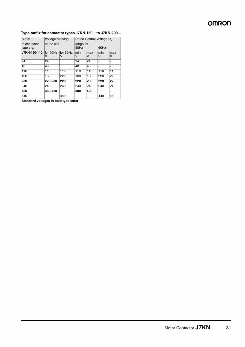
Type-suffix for contactor types J7KN-150... to J7KN-200...
Suffix Voltage Marking Rated Control Voltage Us
to contactor type e.g.
at the coil range for 50Hz 60Hz
J7KN-150-110 for 50HzV
for 60HzV
min V.
max V.
min V.
max V.
24 24 24 24 - -
48 48 48 48 - -
110 110 110 110 110 110 110
180 180 220 180 180 220 220
230 220-230 220 220 230 220 220
240 240 240 240 240 240 240
400 380-400 380 400 - -
440 440 - - 440 440
Standard voltages in bold type letter
32 Motor Contactor J7KN
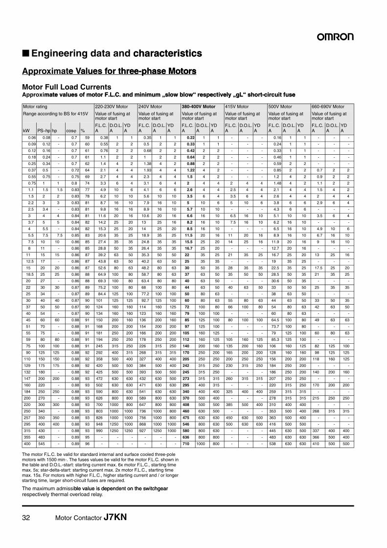
■ Engineering data and characteristicscharacteristics
Approximate Values for three-phase Motorse Values for three-phase Motorshree-phase Motorstors
Motor Full Load CurrentsApproximate values of motor F.L.C. and minimum „slow blow“ respectively „gL“ short-circuit fusemate values of motor F.L.C. and minimum „slow blow“ respectively „gL“ short-circuit fuse
The motor F.L.C. be valid for standard internal and surface cooled three-pole motors with 1500 min-1. The fuses values be valid for the motor F.L.C. shown in the table and D.O.L.-start: starting current max. 6x motor F.L.C., starting time max. 5s; star-delta-start: starting current max. 2x motor F.L.C., starting time max. 15s. For motors with higher F.L.C., higher starting current and / or longer starting time, larger short-circuit fuses are required.
The maximum admissible value is dependent on the switchgear ble value is dependent on the switchgear respectively thermal overload relay.
Motor rating 220-230V Motor 240V Motor 380-400V Motor 415V Motor 500V Motor 660-690V Motor
Range according to BS for 415V Value of fusing at motor start
Value of fusing at motor start
Value of fusing at motor start
Value of fusing at motor start
Value of fusing at motor start
Value of fusing at motor start
kW PS~hp hp cosj %F.L.C.A
D.O.L.A
YDA
F.L.C.A
D.O.L.A
YDA
F.L.C.A
D.O.L.A
YDA
F.L.C.A
D.O.L.A
YDA
F.L.C.A
D.O.L.A
YDA
F.L.C.A
D.O.L.A
YDA
0.06 0.08 - 0.7 59 0.38 1 1 0.35 1 1 0.22 1 1 - - - 0.16 1 1 - - -
0.09 0.12 - 0.7 60 0.55 2 2 0.5 2 2 0.33 1 1 - - - 0.24 1 1 - - -
0.12 0.16 - 0.7 61 0.76 2 2 0.68 2 2 0.42 2 2 - - - 0.33 1 1 - - -
0.18 0.24 - 0.7 61 1.1 2 2 1 2 2 0.64 2 2 - - - 0.46 1 1 - - -
0.25 0.34 - 0.7 62 1.4 4 2 1.38 4 2 0.88 2 2 - - - 0.59 2 2 - - -
0.37 0.5 - 0.72 64 2.1 4 4 1.93 4 4 1.22 4 2 - - - 0.85 2 2 0.7 2 2
0.55 0.75 - 0.75 69 2.7 4 4 2.3 4 4 1.5 4 2 - - - 1.2 4 2 0.9 2 2
0.75 1 1 0.8 74 3.3 6 4 3.1 6 4 2 4 4 2 4 4 1.48 4 2 1.1 2 2
1.1 1.5 1.5 0.83 77 4.9 10 6 4.1 6 6 2.6 4 4 2.5 4 4 2.1 4 4 1.5 4 2
1.5 2 2 0.83 78 6.2 10 10 5.6 10 10 3.5 6 4 3.5 6 4 2.6 4 4 2 4 4
2.2 3 3 0.83 81 8.7 16 10 7.9 16 10 5 10 6 5 10 6 3.8 6 6 2.9 6 4
2.5 3.4 - 0.83 81 9.8 16 16 8.9 16 10 5.7 10 10 - - - 4.3 6 6 - - -
3 4 4 0.84 81 11.6 20 16 10.6 20 16 6.6 16 10 6.5 16 10 5.1 10 10 3.5 6 4
3.7 5 5 0.84 82 14.2 25 20 13 25 16 8.2 16 10 7.5 16 10 6.2 16 10 - - -
4 5.5 - 0.84 82 15.3 25 20 14 25 20 8.5 16 10 - - - 6.5 16 10 4.9 10 6
5.5 7.5 7.5 0.85 83 20.6 35 25 18.9 35 25 11.5 20 16 11 20 16 8.9 16 10 6.7 16 10
7.5 10 10 0.86 85 27.4 35 35 24.8 35 35 15.5 25 20 14 25 16 11.9 20 16 9 16 10
8 11 - 0.86 85 28.8 50 35 26.4 35 35 16.7 25 20 - - - 12.7 20 16 - - -
11 15 15 0.86 87 39.2 63 50 35.3 50 50 22 35 25 21 35 25 16.7 25 20 13 25 16
12.5 17 - 0.86 87 43.8 63 50 40.2 63 50 25 35 35 - - - 19 35 25 - - -
15 20 20 0.86 87 52.6 80 63 48.2 80 63 30 50 35 28 35 35 22.5 35 25 17.5 25 20
18.5 25 25 0.86 88 64.9 100 80 58.7 80 63 37 63 50 35 50 50 28.5 50 35 21 35 25
20 27 - 0.86 88 69.3 100 80 63.4 80 80 40 63 50 - - - 30.6 50 35 - - -
22 30 30 0.87 89 75.2 100 80 68 100 80 44 63 50 40 63 50 33 50 50 25 35 35
25 34 - 0.87 89 84.4 125 100 77.2 100 100 50 80 63 - - - 38 63 50 - - -
30 40 40 0.87 90 101 125 125 92.7 125 100 60 80 63 55 80 63 44 63 50 33 50 35
37 50 50 0.87 90 124 160 160 114 160 125 72 100 80 66 100 80 54 80 63 42 63 50
40 54 - 0.87 90 134 160 160 123 160 160 79 100 100 - - - 60 80 63 - - -
45 60 60 0.88 91 150 200 160 136 200 160 85 125 100 80 100 100 64.5 100 80 49 63 63
51 70 - 0.88 91 168 200 200 154 200 200 97 125 100 - - - 73.7 100 80 - - -
55 75 - 0.88 91 181 250 200 166 200 200 105 160 125 - - - 79 125 100 60 80 63
59 80 80 0.88 91 194 250 250 178 250 200 112 160 125 105 160 125 85.3 125 100 - - -
75 100 100 0.88 91 245 315 250 226 315 250 140 200 160 135 200 160 106 160 125 82 125 100
90 125 125 0.88 92 292 400 315 268 315 315 170 250 200 165 200 200 128 160 160 98 125 125
110 150 150 0.88 92 358 500 400 327 400 400 205 250 250 200 250 250 156 200 200 118 160 125
129 175 175 0.88 92 420 500 500 384 500 400 242 315 250 230 315 250 184 250 200 - - -
132 180 - 0.88 92 425 500 500 393 500 500 245 315 250 - - - 186 250 200 140 200 160
147 200 200 0.88 93 472 630 630 432 630 500 273 315 315 260 315 315 207 250 250 - - -
160 220 - 0.88 93 502 630 630 471 630 630 295 400 315 - - - 220 315 250 170 200 200
184 250 250 0.88 93 590 800 630 541 630 630 340 400 400 325 400 400 259 315 315 - - -
200 270 - 0.88 93 626 800 800 589 800 630 370 500 400 - - - 278 315 315 215 250 250
220 300 300 0.88 93 700 1000 800 647 800 800 408 500 500 385 500 400 310 400 400 - - -
250 340 - 0.88 93 803 1000 1000 736 1000 800 460 630 500 - - - 353 500 400 268 315 315
257 350 350 0.88 93 826 1000 1000 756 1000 800 475 630 630 450 630 500 363 500 400 - - -
295 400 400 0.88 93 948 1250 1000 868 1000 1000 546 800 630 500 630 630 416 500 500 - - -
315 430 - 0.88 93 990 1250 1250 927 1250 1000 580 800 630 - - - 445 630 500 337 400 400
355 483 - 0.89 95 - - - - - - 636 800 800 - - - 483 630 630 366 500 400
400 545 - 0.89 96 - - - - - - 710 1000 800 - - - 538 630 630 410 500 500
Motor Contactor J7KN 33
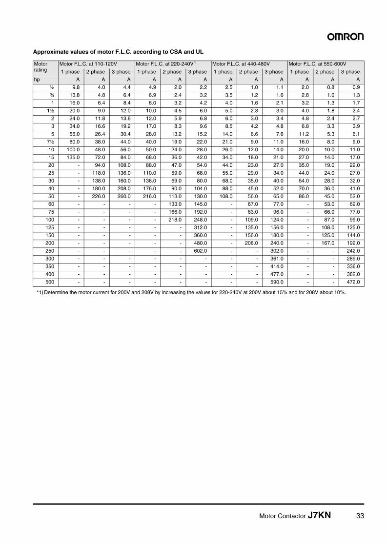
Approximate values of motor F.L.C. according to CSA and UL
Motor rating
Motor F.L.C. at 110-120V Motor F.L.C. at 220-240V*1
*1) Determine the motor current for 200V and 208V by increasing the values for 220-240V at 200V about 15% and for 208V about 10%.
Motor F.L.C. at 440-480V Motor F.L.C. at 550-600V
1-phase 2-phase 3-phase 1-phase 2-phase 3-phase 1-phase 2-phase 3-phase 1-phase 2-phase 3-phase
hp A A A A A A A A A A A A
½ 9.8 4.0 4.4 4.9 2.0 2.2 2.5 1.0 1.1 2.0 0.8 0.9
¾ 13.8 4.8 6.4 6.9 2.4 3.2 3.5 1.2 1.6 2.8 1.0 1.3
1 16.0 6.4 8.4 8.0 3.2 4.2 4.0 1.6 2.1 3.2 1.3 1.7
1½ 20.0 9.0 12.0 10.0 4.5 6.0 5.0 2.3 3.0 4.0 1.8 2.4
2 24.0 11.8 13.6 12.0 5.9 6.8 6.0 3.0 3.4 4.8 2.4 2.7
3 34.0 16.6 19.2 17.0 8.3 9.6 8.5 4.2 4.8 6.8 3.3 3.9
5 56.0 26.4 30.4 28.0 13.2 15.2 14.0 6.6 7.6 11.2 5.3 6.1
7½ 80.0 38.0 44.0 40.0 19.0 22.0 21.0 9.0 11.0 16.0 8.0 9.0
10 100.0 48.0 56.0 50.0 24.0 28.0 26.0 12.0 14.0 20.0 10.0 11.0
15 135.0 72.0 84.0 68.0 36.0 42.0 34.0 18.0 21.0 27.0 14.0 17.0
20 - 94.0 108.0 88.0 47.0 54.0 44.0 23.0 27.0 35.0 19.0 22.0
25 - 118.0 136.0 110.0 59.0 68.0 55.0 29.0 34.0 44.0 24.0 27.0
30 - 138.0 160.0 136.0 69.0 80.0 68.0 35.0 40.0 54.0 28.0 32.0
40 - 180.0 208.0 176.0 90.0 104.0 88.0 45.0 52.0 70.0 36.0 41.0
50 - 226.0 260.0 216.0 113.0 130.0 108.0 56.0 65.0 86.0 45.0 52.0
60 - - - - 133.0 145.0 - 67.0 77.0 - 53.0 62.0
75 - - - - 166.0 192.0 - 83.0 96.0 - 66.0 77.0
100 - - - - 218.0 248.0 - 109.0 124.0 - 87.0 99.0
125 - - - - - 312.0 - 135.0 156.0 - 108.0 125.0
150 - - - - - 360.0 - 156.0 180.0 - 125.0 144.0
200 - - - - - 480.0 - 208.0 240.0 - 167.0 192.0
250 - - - - - 602.0 - - 302.0 - - 242.0
300 - - - - - - - - 361.0 - - 289.0
350 - - - - - - - - 414.0 - - 336.0
400 - - - - - - - - 477.0 - - 382.0
500 - - - - - - - - 590.0 - - 472.0
34 Motor Contactor J7KN
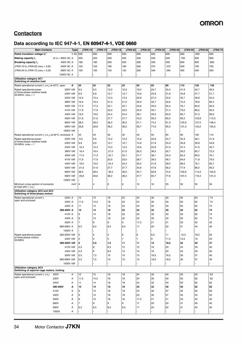
Contactors
Data according to IEC 947-4-1, EN 60947-4-1, VDE 0660N 60947-4-1, VDE 0660Main Contacts Type J7KN-10 J7KN-14 J7KN-18 J7KN-22 J7KN-24 J7KN-32 J7KN-40 J7KN-50 J7KN-62 J7KN-74
Rated insulation voltage Ui*1 V AC 690 690 690 690 690 690 690 690 690 690
Making capacity Ieff at Ue = 690V AC A 200 200 200 200 400 500 500 700 900 900
Breaking capacity Ieff 400V AC A 180 180 200 200 380 400 400 600 800 800
J7KN-10 to J7KN-22 cos� = 0,65 500V AC A 150 150 180 180 300 370 370 500 700 700
J7KN-24 to J7KN-72 cos� = 0,35 690V AC A 100 100 150 150 260 340 340 400 500 500
1000V AC A - - - - - - - - -
Utilization category AC1 Switching of resistive load
Rated operational current Ie (=Ith) at 40°C, open A 25 25 32 32 50 65 80 110 120 130
Rated operational powerof three-phase resistive loads50-60Hz, cos� = 1
220V kW 9,5 9,5 12,2 12,2 19,0 24,7 30,4 41,9 45,7 49,5
230V kW 9,9 9,9 12,7 12,7 19,9 25,9 31,8 43,8 47,7 51,7
240V kW 10,4 10,4 13,3 13,3 20,8 27,0 33,2 45,7 49,8 54,0
380V kW 16,4 16,4 21,0 21,0 32,9 42,7 52,6 72,3 78,9 85,5
400V kW 17,3 17,3 22,1 22,1 34,6 45,0 55,4 76,1 83,0 90,0
415V kW 17,9 17,9 23,0 23,0 35,9 46,7 57,4 79,0 86,2 93,3
440V kW 19,0 19,0 24,4 24,4 38,1 49,5 60,9 83,7 91,3 99,0
500V kW 21,6 21,6 27,7 27,7 43,3 56,2 69,2 95,2 103,8 112,5
660V kW 28,5 28,5 36,5 36,5 57,1 74,2 91,3 125,6 137,0 148,4
690V kW 29,8 29,8 38,2 38,2 59,7 77,6 95,5 131,3 143,2 155,2
1000V kW - - - - - - - - -
Rated operational current Ie (=Ithe) at 60°C, enclosed A 25 25 32 32 40 55 65 90 100 110
Rated operational power of three-phase resistive loads50-60Hz, cos� = 1
220V kW 9,5 9,5 12,2 12,2 15,2 20,9 24,7 34,3 38,1 41,9
230V kW 9,9 9,9 12,7 12,7 15,9 21,9 25,9 35,8 39,8 43,8
240V kW 10,4 10,4 13,3 13,3 16,6 22,8 27,0 37,4 41,5 45,7
380V kW 16,4 16,4 21,0 21,0 26,3 36,2 42,7 59,2 65,7 72,3
400V kW 17,3 17,3 22,1 22,1 27,7 38,1 45,0 62,3 69,2 76,1
415V kW 17,9 17,9 23,0 23,0 28,7 39,5 46,7 64,6 71,8 79,0
440V kW 19,0 19,0 24,4 24,4 30,4 41,9 49,5 68,5 76,1 83,7
500V kW 21,6 21,6 27,7 27,7 34,6 47,6 56,2 77,9 86,5 95,2
660V kW 28,5 28,5 36,5 36,5 45,7 62,8 74,2 102,8 114,2 125,6
690V kW 29,8 29,8 38,2 38,2 47,7 65,7 77,6 107,4 119,4 131,3
1000V kW - - - - - - - - -
Minimum cross-section of conductor at load with Ie (=Ith)
mm² 4 4 6 6 10 16 25 35 50 50
Utilization category AC2 and AC3Switching of three-phase motors
Rated operational current Ie
open and enclosed220V A 12 15 18 22 24 30 40 50 63 74
230V A 11,5 14,5 18 22 24 30 40 50 62 74
240V A 11 14 18 22 24 32 40 50 62 74
380-400V A 10 14 18 22 24 32 40 50 62 74
415V A 9 14 18 22 23 30 40 50 62 74
440V A 9 14 18 22 23 30 40 50 62 74
500V A 7 9 9 9 17,5 21 21 33 42 42
660-690V A 6,5 8,5 8,5 8,5 17 20 20 31 40 40
1000V A - - - - - - - - -
Rated operational power of three-phase motors50-60Hz
220-230V kW 3 4 5 6 6 8,5 11 12,5 18,5 22
240V kW 3 4 5 7 7 9 11,5 13,5 19 23
380-400V kW 4 5,5 7,5 11 11 15 18,5 22 30 37
415V kW 4,5 6 8,5 12 12 16 20 24 33 40
440V kW 4,5 6 8,5 12 12 16 20 24 33 40
500V kW 5,5 7,5 10 10 15 18,5 18,5 30 37 45
660-690V kW 5,5 7,5 10 10 15 18,5 18,5 30 37 45
1000V kW - - - - - - - - -
Utilization category AC4Switching of squirrel cage motors, inching
Rated operational current Ie (=Ith)open and enclosed
220V A 12 15 18 18 24 30 40 50 63 63
230V A 11,5 14,5 18 18 24 30 40 50 62 62
240V A 11 14 18 18 24 32 40 50 62 62
380-400V A 10 14 18 18 24 32 40 50 62 62
415V A 9 14 18 18 23 30 37 45 60 60
440V A 9 14 18 18 23 30 37 45 55 55
500V A 9 12 16 16 17,5 21 21 33 42 42
660V A 7 9 9 9 17 20 20 31 40 40
690V A 6,5 8,5 8,5 8,5 17 20 20 31 40 40
1000V A - - - - - - - - -
Motor Contactor J7KN 35
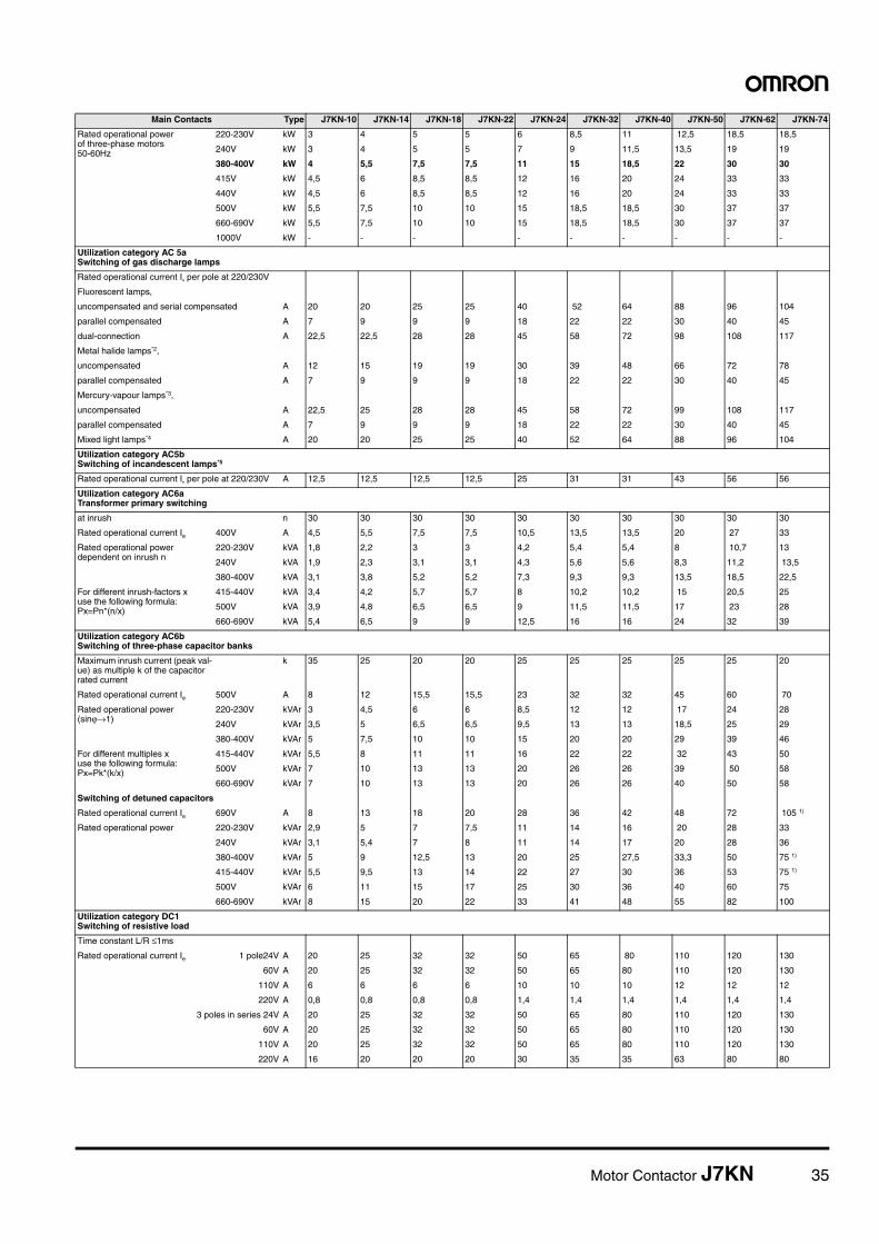
Rated operational power of three-phase motors50-60Hz
220-230V kW 3 4 5 5 6 8,5 11 12,5 18,5 18,5
240V kW 3 4 5 5 7 9 11,5 13,5 19 19
380-400V kW 4 5,5 7,5 7,5 11 15 18,5 22 30 30
415V kW 4,5 6 8,5 8,5 12 16 20 24 33 33
440V kW 4,5 6 8,5 8,5 12 16 20 24 33 33
500V kW 5,5 7,5 10 10 15 18,5 18,5 30 37 37
660-690V kW 5,5 7,5 10 10 15 18,5 18,5 30 37 37
1000V kW - - - - - - - - -
Utilization category AC 5aSwitching of gas discharge lamps
Rated operational current Ie per pole at 220/230V
Fluorescent lamps,
uncompensated and serial compensated A 20 20 25 25 40 52 64 88 96 104
parallel compensated A 7 9 9 9 18 22 22 30 40 45
dual-connection A 22,5 22,5 28 28 45 58 72 98 108 117
Metal halide lamps*2,
uncompensated A 12 15 19 19 30 39 48 66 72 78
parallel compensated A 7 9 9 9 18 22 22 30 40 45
Mercury-vapour lamps*3,
uncompensated A 22,5 25 28 28 45 58 72 99 108 117
parallel compensated A 7 9 9 9 18 22 22 30 40 45
Mixed light lamps*4 A 20 20 25 25 40 52 64 88 96 104
Utilization category AC5bSwitching of incandescent lamps*5
Rated operational current Ie per pole at 220/230V A 12,5 12,5 12,5 12,5 25 31 31 43 56 56
Utilization category AC6aTransformer primary switching
at inrush n 30 30 30 30 30 30 30 30 30 30
Rated operational current Ie 400V A 4,5 5,5 7,5 7,5 10,5 13,5 13,5 20 27 33
Rated operational power dependent on inrush n
220-230V kVA 1,8 2,2 3 3 4,2 5,4 5,4 8 10,7 13
240V kVA 1,9 2,3 3,1 3,1 4,3 5,6 5,6 8,3 11,2 13,5
380-400V kVA 3,1 3,8 5,2 5,2 7,3 9,3 9,3 13,5 18,5 22,5
For different inrush-factors xuse the following formula:Px=Pn*(n/x)
415-440V kVA 3,4 4,2 5,7 5,7 8 10,2 10,2 15 20,5 25
500V kVA 3,9 4,8 6,5 6,5 9 11,5 11,5 17 23 28
660-690V kVA 5,4 6,5 9 9 12,5 16 16 24 32 39
Utilization category AC6bSwitching of three-phase capacitor banks
Maximum inrush current (peak val-ue) as multiple k of the capacitor rated current
k 35 25 20 20 25 25 25 25 25 20
Rated operational current Ie 500V A 8 12 15,5 15,5 23 32 32 45 60 70
Rated operational power(sinjÆ1)
220-230V kVAr 3 4,5 6 6 8,5 12 12 17 24 28
240V kVAr 3,5 5 6,5 6,5 9,5 13 13 18,5 25 29
380-400V kVAr 5 7,5 10 10 15 20 20 29 39 46
For different multiples x use the following formula:Px=Pk*(k/x)
415-440V kVAr 5,5 8 11 11 16 22 22 32 43 50
500V kVAr 7 10 13 13 20 26 26 39 50 58
660-690V kVAr 7 10 13 13 20 26 26 40 50 58
Switching of detuned capacitors
Rated operational current Ie 690V A 8 13 18 20 28 36 42 48 72 105 1)
Rated operational power 220-230V kVAr 2,9 5 7 7,5 11 14 16 20 28 33
240V kVAr 3,1 5,4 7 8 11 14 17 20 28 36
380-400V kVAr 5 9 12,5 13 20 25 27,5 33,3 50 75 1)
415-440V kVAr 5,5 9,5 13 14 22 27 30 36 53 75 1)
500V kVAr 6 11 15 17 25 30 36 40 60 75
660-690V kVAr 8 15 20 22 33 41 48 55 82 100
Utilization category DC1Switching of resistive load
Time constant L/R £1ms
Rated operational current Ie 1 pole24V A 20 25 32 32 50 65 80 110 120 130
60V A 20 25 32 32 50 65 80 110 120 130
110V A 6 6 6 6 10 10 10 12 12 12
220V A 0,8 0,8 0,8 0,8 1,4 1,4 1,4 1,4 1,4 1,4
3 poles in series 24V A 20 25 32 32 50 65 80 110 120 130
60V A 20 25 32 32 50 65 80 110 120 130
110V A 20 25 32 32 50 65 80 110 120 130
220V A 16 20 20 20 30 35 35 63 80 80
Main Contacts Type J7KN-10 J7KN-14 J7KN-18 J7KN-22 J7KN-24 J7KN-32 J7KN-40 J7KN-50 J7KN-62 J7KN-74
36 Motor Contactor J7KN
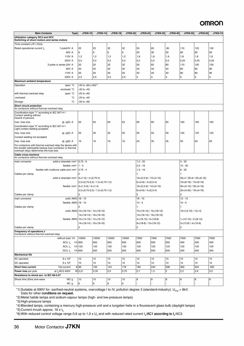
Utilization category DC3 and DC5Switching of shunt motors and series motors
Time constant L/R £15ms
Rated operational current Ie 1 pole24V A 20 25 32 32 50 65 80 110 120 130
60V A 6 6 6 6 30 30 30 60 60 60
110V A 1,2 1,2 1,2 1,2 1,8 1,8 1,8 1,8 1,8 1,8
220V A 0,2 0,2 0,2 0,2 0,2 0,2 0,2 0,25 0,25 0,25
3 poles in series 24V A 20 25 32 32 50 65 80 110 120 130
60V A 20 25 32 32 40 40 40 80 80 80
110V A 20 20 20 20 40 40 40 80 80 80
220V A 2,5 2,5 2,5 2,5 4 4 4 5 5 5
Maximum ambient temperature
Operation open °C -40 to +60 (+90)*6
enclosed °C -40 to +40
with thermal overload relay open °C -25 to +60
enclosed °C -25 to +40
Storage °C -50 to +90
Short circuit protectionfor contactors without thermal overload relay
Coordination-type "1" according to IEC 947-4-1Contact welding withouthazard of persons
max. fuse size gL (gG) A 63 63 63 63 80 80 80 160 160 160
Coordination-type “2” according to IEC 947-4-1Light contact welding accepted
max. fuse size gL (gG) A 25 35 35 35 50 50 50 100 125 125
Contact welding not accepted
max. fuse size gL (gG) A 16 16 16 16 25 35 35 50 63 63
For contactors with thermal overload relay the device with the smaller admissible backup fuse (contactor or thermal overload relay) determines the fuse size.
Cable cross-sectionsfor contactors without thermal overload relay
main connector solid or stranded mm² 0,75 - 6 1,5 - 25 4 - 50
flexible mm² 1 - 4 2,5 - 16 10 - 35
flexible with multicore cable end mm² 0,75 - 4 1,5 - 16 6 - 35
Cables per clamp 2 1 1
solid or stranded mm² 6+(1-6) / 4+(0,75-4) 16+(2,5-6) / 10+(4-10) 50+4 / 35+6 / 25+(6-16)
2,5+(0,75-2,5) / 1,5+(0,75-1,5) 6+(4-6) / 4+(2,5-4) 16+(6-16) / 10+(6-16)
flexible mm² 6+(1,5-6) / 4+(1-4) 16+(2,5-6) / 10+(4-10) 50+(4-10) / 35+(4-16)
2,5+(0,75-2,5) / 1,5+(0,75-1,5) 6+(4-6) / 4+(2,5-4) 25+(4-25) / 16+(4-16)
Cables per clamp 2 2 2
main connector solid AWG 18 - 10 16 - 10 12 - 10
flexible AWG 18 - 10 14 - 4 10 - 0
Cables per clamp 2 1 1
solid AWG 10+(16-10) / 12+(18-12) 10+(16-10) / 12+(18-12) 10+(12-10) / 12+12
14+(18-14) / 16+(18-16) 14+(18-14) / 16+(18-16)
flexible AWG 10+(14-10) / 12+(18-12) 4+(18-12) / 6+(18-8) 1+(12-10) / 2+(8-12)
14+(18-14) / 16+(18-16) 8+(18-8) / 10+(18-12) 3+(12-8) / 4+(10-6)
Cables per clamp 2 2 2
Frequency of operations zContactors without thermal overload relay
without load 1/h 10000 10000 10000 10000 7000 7000 7000 7000 7000 7000
AC3, Ie 1/h 600 600 600 600 600 600 600 400 400 400
AC4, Ie 1/h 120 120 120 120 120 120 120 120 120 120
DC3, Ie 1/h 600 600 600 600 600 600 600 400 400 400
Mechanical life
AC operated S x 106 10 10 10 10 10 10 10 10 10 10
DC operated S x 106 10 10 10 10 10 10 10 10 10 10
Short time current 10s-current A 96 120 144 176 184 240 296 360 504 592
Power loss per pole at Ie/AC3 400V W 0,21 0,35 0,5 0,75 0,7 1,3 2 2,2 3,9 5,5
Resistance to shock acc. to IEC 68-2-27
Shock time 20ms sine-wave NO g 10 10 10 10 8 8 8 8 8 8
NC g 6 6 6 6 - - - - - -
*1) Suitable at 690V for: earthed-neutral systems, overvoltage I to IV, pollution degree 3 (standard-industry): Uimp = 8kV. Data for other conditions on request.conditions on request.
*2) Metal halide lamps and sodium-vapour lamps (high- and low-pressure lamps)*3) High-pressure lamps*4) Blended lamps, containing a mercury high-pressure unit and a tungsten helix in a flourescent glass bulb (daylight lamps)*5) Current inrush approx. 16 x Ie*6) With reduced control voltage range 0,9 up to 1,0 x Us and with reduced rated current Ie/AC1 according to IAC1 according to Ie/AC3
Main Contacts Type J7KN-10 J7KN-14 J7KN-18 J7KN-22 J7KN-24 J7KN-32 J7KN-40 J7KN-50 J7KN-62 J7KN-74
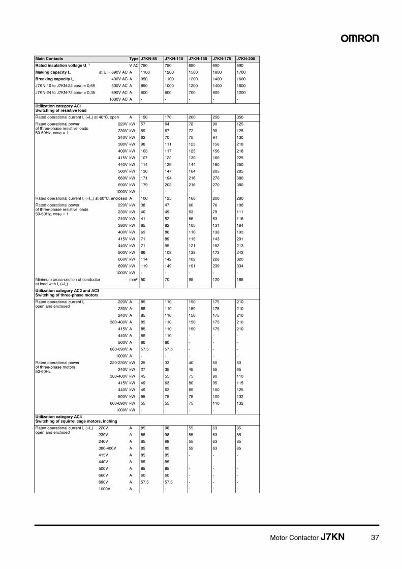
Motor Contactor J7KN 37
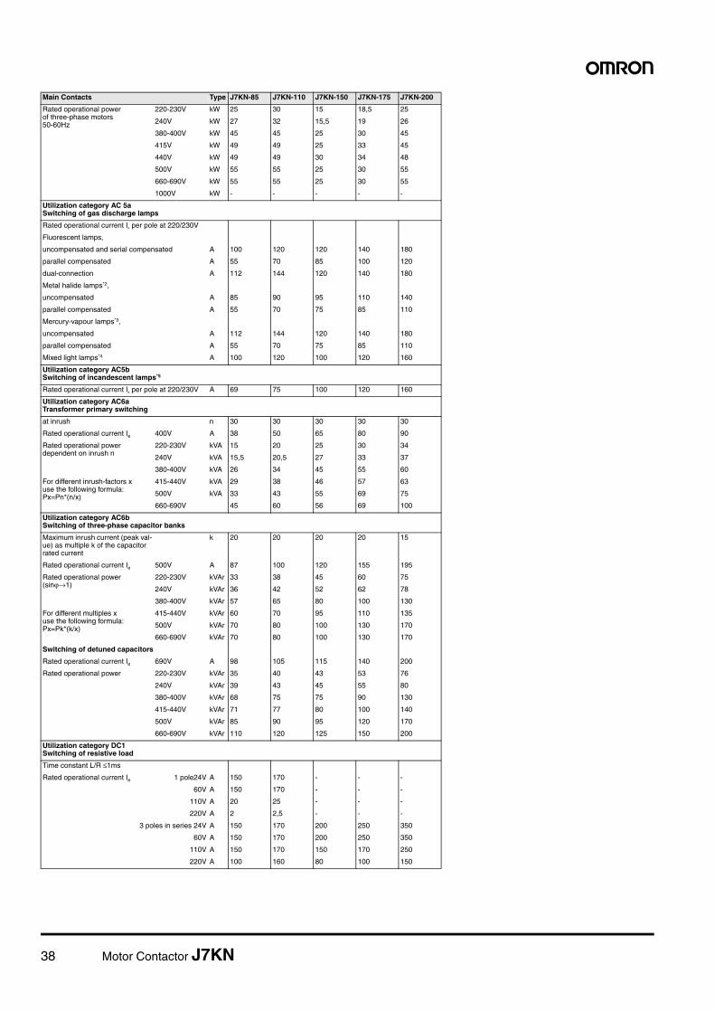
Main Contacts Type J7KN-85 J7KN-110 J7KN-150 J7KN-175 J7KN-200
Rated insulation voltage Ui *1 V AC 750 750 690 690 690
Making capacity Ieff at Ue = 690V AC A 1100 1200 1500 1800 1700
Breaking capacity Ieff 400V AC A 950 1100 1200 1400 1600
J7KN-10 to J7KN-22 cos� = 0,65 500V AC A 850 1000 1200 1400 1600
J7KN-24 to J7KN-72 cos� = 0,35 690V AC A 600 600 700 800 1200
1000V AC A - - - - -
Utilization category AC1 Switching of resistive load
Rated operational current Ie (=Ith) at 40°C, open A 150 170 200 250 350
Rated operational powerof three-phase resistive loads50-60Hz, cos� = 1
220V kW 57 64 72 90 125
230V kW 59 67 72 90 125
240V kW 62 70 75 94 130
380V kW 98 111 125 156 218
400V kW 103 117 125 156 218
415V kW 107 122 130 160 225
440V kW 114 129 144 180 250
500V kW 130 147 164 205 285
660V kW 171 194 216 270 380
690V kW 179 203 216 270 380
1000V kW - - - - -
Rated operational current Ie (=Ithe) at 60°C, enclosed A 100 125 160 200 280
Rated operational power of three-phase resistive loads50-60Hz, cos� = 1
220V kW 38 47 60 76 106
230V kW 40 49 63 79 111
240V kW 41 52 66 83 116
380V kW 65 82 105 131 184
400V kW 69 86 110 138 193
415V kW 71 89 115 143 201
440V kW 71 95 121 152 213
500V kW 86 108 138 173 242
660V kW 114 142 182 228 320
690V kW 119 149 191 239 334
1000V kW - - - - -
Minimum cross-section of conductor at load with Ie (=Ith)
mm² 50 70 95 120 185
Utilization category AC2 and AC3Switching of three-phase motors
Rated operational current Ie
open and enclosed220V A 85 110 150 175 210
230V A 85 110 150 175 210
240V A 85 110 150 175 210
380-400V A 85 110 150 175 210
415V A 85 110 150 175 210
440V A 85 110 - - -
500V A 60 60 - - -
660-690V A 57,5 57,5 - - -
1000V A - - - - -
Rated operational power of three-phase motors50-60Hz
220-230V kW 25 33 40 50 60
240V kW 27 35 45 55 65
380-400V kW 45 55 75 90 110
415V kW 49 63 80 95 115
440V kW 49 63 85 100 125
500V kW 55 75 75 100 132
660-690V kW 55 55 75 110 132
1000V kW - - - - -
Utilization category AC4Switching of squirrel cage motors, inching
Rated operational current Ie (=Ith)open and enclosed
220V A 85 98 55 63 85
230V A 85 98 55 63 85
240V A 85 98 55 63 85
380-400V A 85 85 55 63 85
415V A 85 85 - - -
440V A 85 85 - - -
500V A 85 85 - - -
660V A 60 60 - - -
690V A 57,5 57,5 - - -
1000V A - - - - -
38 Motor Contactor J7KN
Rated operational power of three-phase motors50-60Hz
220-230V kW 25 30 15 18,5 25
240V kW 27 32 15,5 19 26
380-400V kW 45 45 25 30 45
415V kW 49 49 25 33 45
440V kW 49 49 30 34 48
500V kW 55 55 25 30 55
660-690V kW 55 55 25 30 55
1000V kW - - - - -
Utilization category AC 5aSwitching of gas discharge lamps
Rated operational current Ie per pole at 220/230V
Fluorescent lamps,
uncompensated and serial compensated A 100 120 120 140 180
parallel compensated A 55 70 85 100 120
dual-connection A 112 144 120 140 180
Metal halide lamps*2,
uncompensated A 85 90 95 110 140
parallel compensated A 55 70 75 85 110
Mercury-vapour lamps*3,
uncompensated A 112 144 120 140 180
parallel compensated A 55 70 75 85 110
Mixed light lamps*4 A 100 120 100 120 160
Utilization category AC5bSwitching of incandescent lamps*5
Rated operational current Ie per pole at 220/230V A 69 75 100 120 160
Utilization category AC6aTransformer primary switching
at inrush n 30 30 30 30 30
Rated operational current Ie 400V A 38 50 65 80 90
Rated operational power dependent on inrush n
220-230V kVA 15 20 25 30 34
240V kVA 15,5 20,5 27 33 37
380-400V kVA 26 34 45 55 60
For different inrush-factors xuse the following formula:Px=Pn*(n/x)
415-440V kVA 29 38 46 57 63
500V kVA 33 43 55 69 75
660-690V 45 60 56 69 100
Utilization category AC6bSwitching of three-phase capacitor banks
Maximum inrush current (peak val-ue) as multiple k of the capacitor rated current
k 20 20 20 20 15
Rated operational current Ie 500V A 87 100 120 155 195
Rated operational power(sinjÆ1)
220-230V kVAr 33 38 45 60 75
240V kVAr 36 42 52 62 78
380-400V kVAr 57 65 80 100 130
For different multiples x use the following formula:Px=Pk*(k/x)
415-440V kVAr 60 70 95 110 135
500V kVAr 70 80 100 130 170
660-690V kVAr 70 80 100 130 170
Switching of detuned capacitors
Rated operational current Ie 690V A 98 105 115 140 200
Rated operational power 220-230V kVAr 35 40 43 53 76
240V kVAr 39 43 45 55 80
380-400V kVAr 68 75 75 90 130
415-440V kVAr 71 77 80 100 140
500V kVAr 85 90 95 120 170
660-690V kVAr 110 120 125 150 200
Utilization category DC1Switching of resistive load
Time constant L/R £1ms
Rated operational current Ie 1 pole24V A 150 170 - - -
60V A 150 170 - - -
110V A 20 25 - - -
220V A 2 2,5 - - -
3 poles in series 24V A 150 170 200 250 350
60V A 150 170 200 250 350
110V A 150 170 150 170 250
220V A 100 160 80 100 150
Main Contacts Type J7KN-85 J7KN-110 J7KN-150 J7KN-175 J7KN-200
Motor Contactor J7KN 39
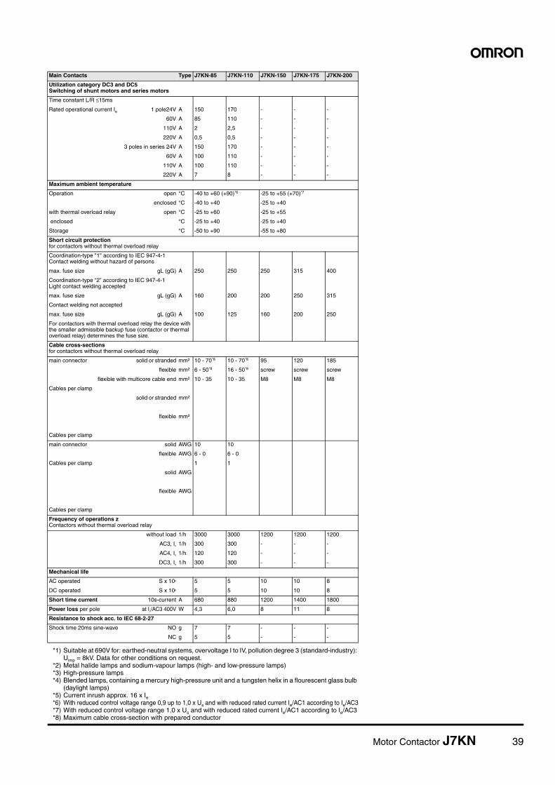
Utilization category DC3 and DC5Switching of shunt motors and series motors
Time constant L/R £15ms
Rated operational current Ie 1 pole24V A 150 170 - - -
60V A 85 110 - - -
110V A 2 2,5 - - -
220V A 0,5 0,5 - - -
3 poles in series 24V A 150 170 - - -
60V A 100 110 - - -
110V A 100 110 - - -
220V A 7 8 - - -
Maximum ambient temperature
Operation open °C -40 to +60 (+90)*6 -25 to +55 (+70)*7
enclosed °C -40 to +40 -25 to +40
with thermal overload relay open °C -25 to +60 -25 to +55
enclosed °C -25 to +40 -25 to +40
Storage °C -50 to +90 -55 to +80
Short circuit protectionfor contactors without thermal overload relay
Coordination-type "1" according to IEC 947-4-1Contact welding without hazard of persons
max. fuse size gL (gG) A 250 250 250 315 400
Coordination-type “2” according to IEC 947-4-1Light contact welding accepted
max. fuse size gL (gG) A 160 200 200 250 315
Contact welding not accepted
max. fuse size gL (gG) A 100 125 160 200 250
For contactors with thermal overload relay the device with the smaller admissible backup fuse (contactor or thermal overload relay) determines the fuse size.
Cable cross-sectionsfor contactors without thermal overload relay
main connector solid or stranded mm² 10 - 70*8 10 - 70*8 95 120 185
flexible mm² 6 - 50*8 16 - 50*8 screw screw screw
flexible with multicore cable end mm² 10 - 35 10 - 35 M8 M8 M8
Cables per clamp
solid or stranded mm²
flexible mm²
Cables per clamp
main connector solid AWG 10 10
flexible AWG 6 - 0 6 - 0
Cables per clamp 1 1
solid AWG
flexible AWG
Cables per clamp
Frequency of operations zContactors without thermal overload relay
without load 1/h 3000 3000 1200 1200 1200
AC3, Ie 1/h 300 300 - - -
AC4, Ie 1/h 120 120 - - -
DC3, Ie 1/h 300 300 - - -
Mechanical life
AC operated S x 106 5 5 10 10 8
DC operated S x 106 5 5 10 10 8
Short time current 10s-current A 680 880 1200 1400 1800
Power loss per pole at Ie/AC3 400V W 4,3 6,0 8 11 8
Resistance to shock acc. to IEC 68-2-27
Shock time 20ms sine-wave NO g 7 7 - - -
NC g 5 5 - - -
*1) Suitable at 690V for: earthed-neutral systems, overvoltage I to IV, pollution degree 3 (standard-industry): Uimp = 8kV. Data for other conditions on request.
*2) Metal halide lamps and sodium-vapour lamps (high- and low-pressure lamps)*3) High-pressure lamps*4) Blended lamps, containing a mercury high-pressure unit and a tungsten helix in a flourescent glass bulb
(daylight lamps)*5) Current inrush approx. 16 x Ie*6) With reduced control voltage range 0,9 up to 1,0 x Us and with reduced rated current Ie/AC1 according to Ie/AC3*7) With reduced control voltage range 1,0 x Us and with reduced rated current Ie/AC1 according to Ie/AC3*8) Maximum cable cross-section with prepared conductor
Main Contacts Type J7KN-85 J7KN-110 J7KN-150 J7KN-175 J7KN-200
40 Motor Contactor J7KN
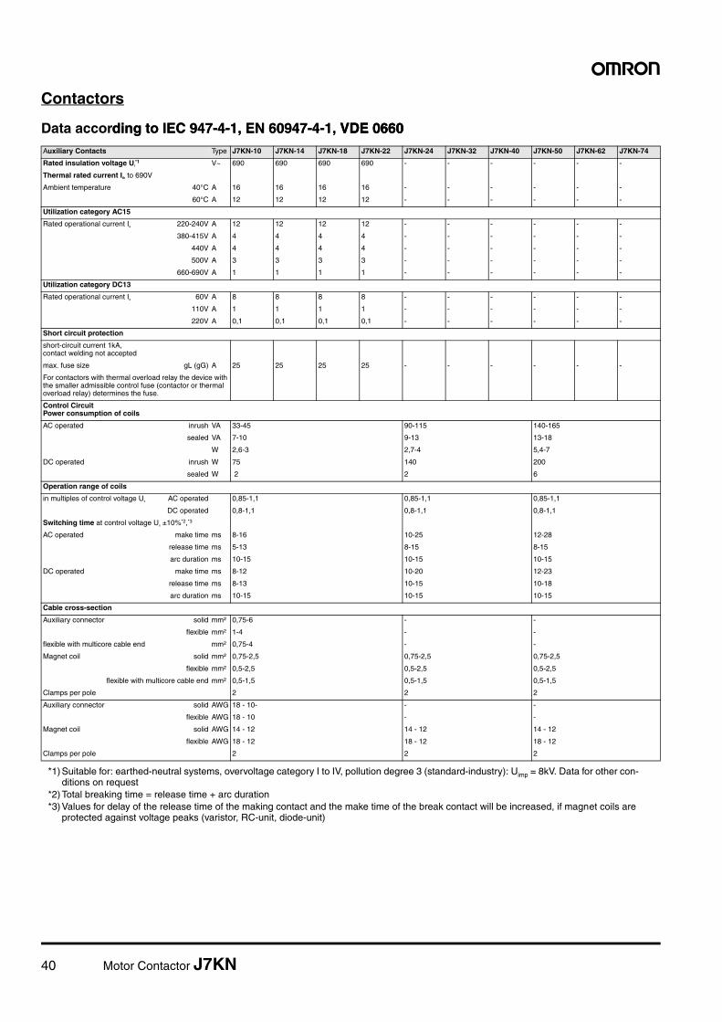
Contactors
Data according to IEC 947-4-1, EN 60947-4-1, VDE 0660ding to IEC 947-4-1, EN 60947-4-1, VDE 0660VDE 0660Auxiliary Contacts Type J7KN-10 J7KN-14 J7KN-18 J7KN-22 J7KN-24 J7KN-32 J7KN-40 J7KN-50 J7KN-62 J7KN-74
Rated insulation voltage Ui*1
*1) Suitable for: earthed-neutral systems, overvoltage category I to IV, pollution degree 3 (standard-industry): Uimp = 8kV. Data for other con-ditions on request
V~ 690 690 690 690 - - - - - -
Thermal rated current Ith to 690V
Ambient temperature 40°C A 16 16 16 16 - - - - - -
60°C A 12 12 12 12 - - - - - -
Utilization category AC15
Rated operational current Ie 220-240V A 12 12 12 12 - - - - - -
380-415V A 4 4 4 4 - - - - - -
440V A 4 4 4 4 - - - - - -
500V A 3 3 3 3 - - - - - -
660-690V A 1 1 1 1 - - - - - -
Utilization category DC13
Rated operational current Ie 60V A 8 8 8 8 - - - - - -
110V A 1 1 1 1 - - - - - -
220V A 0,1 0,1 0,1 0,1 - - - - - -
Short circuit protection
short-circuit current 1kA, contact welding not accepted
max. fuse size gL (gG) A 25 25 25 25 - - - - - -
For contactors with thermal overload relay the device with the smaller admissible control fuse (contactor or thermal overload relay) determines the fuse.
Control CircuitPower consumption of coils
AC operated inrush VA 33-45 90-115 140-165
sealed VA 7-10 9-13 13-18
W 2,6-3 2,7-4 5,4-7
DC operated inrush W 75 140 200
sealed W 2 2 6
Operation range of coils
in multiples of control voltage Us AC operated 0,85-1,1 0,85-1,1 0,85-1,1
DC operated 0,8-1,1 0,8-1,1 0,8-1,1
Switching time at control voltage Us ±10%*2,*3
*2) Total breaking time = release time + arc duration*3) Values for delay of the release time of the making contact and the make time of the break contact will be increased, if magnet coils are
protected against voltage peaks (varistor, RC-unit, diode-unit)
AC operated make time ms 8-16 10-25 12-28
release time ms 5-13 8-15 8-15
arc duration ms 10-15 10-15 10-15
DC operated make time ms 8-12 10-20 12-23
release time ms 8-13 10-15 10-18
arc duration ms 10-15 10-15 10-15
Cable cross-section
Auxiliary connector solid mm² 0,75-6 - -
flexible mm² 1-4 - -
flexible with multicore cable end mm² 0,75-4 - -
Magnet coil solid mm² 0,75-2,5 0,75-2,5 0,75-2,5
flexible mm² 0,5-2,5 0,5-2,5 0,5-2,5
flexible with multicore cable end mm² 0,5-1,5 0,5-1,5 0,5-1,5
Clamps per pole 2 2 2
Auxiliary connector solid AWG 18 - 10- - -
flexible AWG 18 - 10 - -
Magnet coil solid AWG 14 - 12 14 - 12 14 - 12
flexible AWG 18 - 12 18 - 12 18 - 12
Clamps per pole 2 2 2
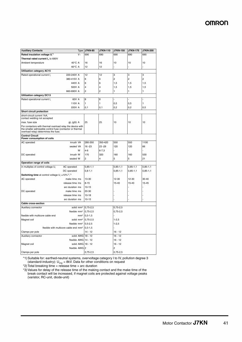
Motor Contactor J7KN 41
Auxiliary Contacts Type J7KN-85 J7KN-110 J7KN-150 J7KN-175 J7KN-200
Rated insulation voltage Ui*1
*1) Suitable for: earthed-neutral systems, overvoltage category I to IV, pollution degree 3 (standard-industry): Uimp = 8kV. Data for other conditions on request
V~ 690 690 690 690 690
Thermal rated current Ith to 690V
Ambient temperature 40°C A 16 16 10 10 10
60°C A 12 12 - - -
Utilization category AC15
Rated operational current Ie 220-240V A 12 12 3 3 3
380-415V A 6 6 2 2 2
440V A 6 6 1,5 1,5 1,5
500V A 4 4 1,5 1,5 1,5
660-690V A 2 2 1 1 1
Utilization category DC13
Rated operational current Ie 60V A 8 8 - - -
110V A 1 1 0,5 0,5 1
220V A 0,1 0,1 0,2 0,2 0,5
Short circuit protection
short-circuit current 1kA, contact welding not accepted
max. fuse size gL (gG) A 25 25 10 10 10
For contactors with thermal overload relay the device with the smaller admissible control fuse (contactor or thermal overload relay) determines the fuse.
Control CircuitPower consumption of coils
AC operated inrush VA 280-350 350-420 550 550 1100
sealed VA 16 -23 23 -29 120 120 66
W 4-6 6-7,3 - - -
DC operated inrush W 170 320 160 160 530
sealed W 2 4 5 5 21
Operation range of coils
in multiples of control voltage Us AC operated 0,85-1,1 0,85-1,1 0,85-1,1 0,85-1,1
DC operated 0,8-1,1 0,85-1,1 0,85-1,1 0,85-1,1
Switching time at control voltage Us ±10%*2,*3
*2) Total breaking time = release time + arc duration*3) Values for delay of the release time of the making contact and the make time of the
break contact will be increased, if magnet coils are protected against voltage peaks (varistor, RC-unit, diode-unit)
AC operated make time ms 13-30 12-30 12-30 30-40
release time ms 8-15 15-40 15-40 15-45
arc duration ms 10-15 - -
DC operated make time ms 20-30 - - -
release time ms 10-18 - - -
arc duration ms 10-15 - - -
Cable cross-section
Auxiliary connector solid mm² 0,75-2,5 0,75-2,5
flexible mm² 0,75-2,5 0,75-2,5
flexible with multicore cable end mm² 0,5-1,5 -
Magnet coil solid mm² 0,75-2,5 1-2,5
flexible mm² 0,5-2,5 1-2,5
flexible with multicore cable end mm² 0,5-1,5 -
Clamps per pole 14 - 12 16 - 12
Auxiliary connector solid AWG 18 - 12 16 - 12
flexible AWG 14 - 12 16 - 12
Magnet coil solid AWG 18 - 12 16 - 12
flexible AWG 2 2
Clamps per pole 0,75-2,5 0,75-2,5
42 Motor Contactor J7KN
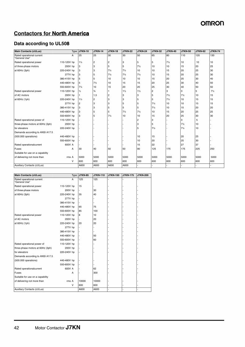
Contactors for North AmericaNorth Americaca
Data according to UL5088Main Contacts (cULus) Type J7KN-10 J7KN-14 J7KN-18 J7KN-22 J7KN-24 J7KN-32 J7KN-40 J7KN-50 J7KN-62 J7KN-74
Rated operational current "General Use"
A 25 25 30 30 50 65 80 110 120 130
Rated operational power 110-120V hp 1½ 2 2 3 5 5 7½ 10 10 10
of three-phase motors 200V hp 3 3 5 5 7½ 10 10 15 20 25
at 60Hz (3ph) 220-240V hp 3 3 7½ 7½ 10 10 15 20 25 30
277V hp 3 5 7½ 7½ 7½ 10 15 20 25 30
380-415V hp 5 5 10 10 10 15 20 25 30 40
440-480V hp 5 7½ 10 15 15 20 25 30 40 50
550-600V hp 7½ 10 15 20 20 25 30 40 50 50
Rated operational power 110-120V hp ½ ¾ 1 1½ 1½ 2 3 3 5 7½
of AC motors 200V hp 1 1,5 2 3 3 5 7½ 7½ 10 15
at 60Hz (1ph) 220-240V hp 1½ 2 3 3 5 5 7½ 10 15 15
277V hp 2 3 3 5 5 7½ 10 10 15 15
380-415V hp 3 3 5 5 5 7½ 10 15 20 20
440-480V hp 3 5 5 7½ 7½ 10 15 20 25 25
550-600V hp 3 5 7½ 10 10 15 20 25 30 30
Rated operational power of 110-120V hp - - - - 2 3 - 3 5 -
three-phase motors at 60Hz (3ph) 200V hp - - - - 3 5 - 7½ 10 -
for elevators 220-240V hp - - - - 5 7½ - 7½ 10 -
Demands according to ANSI A17.5
(500.000 operations) 440-480V hp - - - - 10 15 - 20 25 -
550-600V hp - - - - 10 20 - 25 30 -
Rated operationalcurrent 600V A - - - - 15 22 - 27 37 -
Fuses A 30 40 50 50 90 125 175 175 225 250
Suitable for use on a capability
of delivering not more than rms A 5000 5000 5000 5000 5000 5000 5000 5000 5000 5000
V 600 600 600 600 600 600 600 600 600 600
Auxiliary Contacts (cULus) A600 A600 A600 A600 - - - - - -
Main Contacts (cULus) Type J7KN-85 J7KN-110 J7KN-150 J7KN-175 J7KN-200
Rated operational current "General Use"
A 125 125 - - -
Rated operational power 110-120V hp 15 - - - -
of three-phase motors 200V hp - 30 - - -
at 60Hz (3ph) 220-240V hp 35 40 - - -
277V hp - - - - -
380-415V hp - - - - -
440-480V hp 65 75 - - -
550-600V hp 85 100 - - -
Rated operational power 110-120V hp 8 10 - - -
of AC motors 200V hp - 20 - - -
at 60Hz (1ph) 220-240V hp 20 20 - - -
277V hp - - - - -
380-415V hp - - - - -
440-480V hp - 50 - - -
550-600V hp - 60 - - -
Rated operational power of 110-120V hp - - - - -
three-phase motors at 60Hz (3ph) 200V hp - - - - -
for elevators 220-240V hp - - - - -
Demands according to ANSI A17.5
(500.000 operations) 440-480V hp - - - - -
550-600V hp - - - - -
Rated operationalcurrent 600V A - 62 - - -
Fuses A - 300 - - -
Suitable for use on a capability
of delivering not more than rms A 10000 10000 - - -
V 600 600 - - -
Auxiliary Contacts (cULus) A600 A600 - - -
Motor Contactor J7KN 43
Contactors
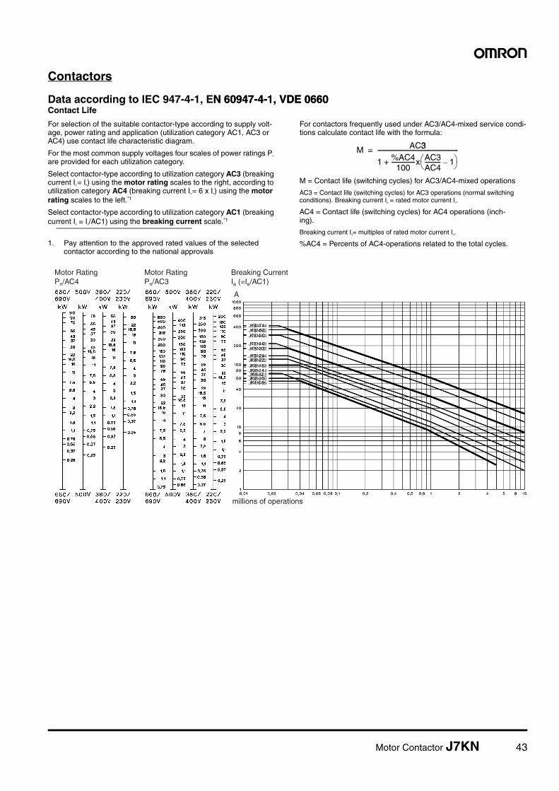
Data according to IEC 947-4-1, EN 60947-4-1, VDE 0660N 60947-4-1, VDE 0660Contact Life
For selection of the suitable contactor-type according to supply volt-age, power rating and application (utilization category AC1, AC3 or AC4) use contact life characteristic diagram.
For the most common supply voltages four scales of power ratings Pn are provided for each utilization category.
Select contactor-type according to utilization category AC3 (breaking current Ia = Ie) using the motor rating scales to the right, according to utilization category AC4 (breaking current Ia = 6 x Ie) using the motor rating scales to the left.*1
Select contactor-type according to utilization category AC1 (breaking current Ia = Ie/AC1) using the breaking current scale.*1
For contactors frequently used under AC3/AC4-mixed service condi-tions calculate contact life with the formula:
1. Pay attention to the approved rated values of the selectedcontactor according to the national approvals
M AC33
1 %AC4100
-----------------x AC3AC4----------- 1–� �� �+
---------------------------------------------------------=
M = Contact life (switching cycles) for AC3/AC4-mixed operations
AC3 = Contact life (switching cycles) for AC3 operations (normal switching conditions). Breaking current Ia = rated motor current In.
AC4 = Contact life (switching cycles) for AC4 operations (inch-ing).
Breaking current Ia= multiples of rated motor current In.
%AC4 = Percents of AC4-operations related to the total cycles.
A
Motor RatingPn/AC4
Motor RatingPn/AC3
Breaking CurrentIa (=Ie/AC1)
J7KN-74
J7KN-24
J7KN-32J7KN-40
J7KN-50J7KN-62
J7KN-22J7KN-18J7KN-14J7KN-12J7KN-10J7KN-09
millions of operations
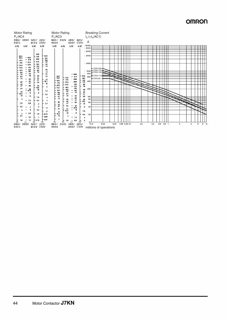
44 Motor Contactor J7KN
A
Motor RatingPn/AC4
Motor RatingPn/AC3
Breaking CurrentIa (=Ie/AC1)
J7KN-200
J7KN-150J7KN-175
J7KN-110
J7KN-85
millions of operations
Motor Contactor J7KN 45
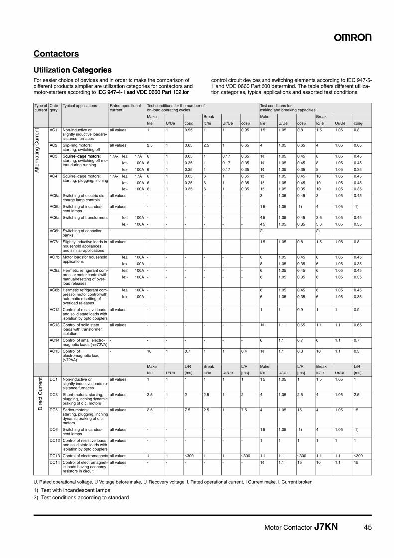
Contactors
Utilization Categorieson CategoriesFor easier choice of devices and in order to make the comparison of different products simplier are utilization categories for contactors and motor-starters according to IEC 947-4-1 and VDE 0660 Part 102,for EC 947-4-1 and VDE 0660 Part 102,for
control circuit devices and switching elements according to IEC 947-5-1 and VDE 0660 Part 200 determind. The table offers different utiliza-tion categories, typical applications and assorted test conditions.
Ue Rated operational voltage, U Voltage before make, Ur Recovery voltage, Ie Rated operational current, I Current make, Ic Current broken
1) Test with incandescent lamps2) Test conditions according to standard
Type of current
Cate-gory
Typical applications Rated operational current
Test conditions for the number ofon-load operating cycles
Test conditions for making and breaking capacities
Make Break Make Break
I/Ie U/Ue cosj Ic/Ie Ur/Ue cosj I/Ie U/Ue cosj Ic/Ie Ur/Ue cosj
Alte
rnat
ing
Cur
rent AC1 Non-inductive or
slightly inductive loadsre-sistance furnaces
all values 1 1 0.95 1 1 0.95 1.5 1.05 0.8 1.5 1.05 0.8
AC2 Slip-ring motors:starting, switching off
all values 2.5 1 0.65 2.5 1 0.65 4 1.05 0.65 4 1.05 0.65
AC3 Squirrel-cage motors: quirrel-cage motors: starting, switching off mo-tors during running
17A< Ie£ 17A 6 1 0.65 1 0.17 0.65 10 1.05 0.45 8 1.05 0.45
Ie£ 100A 6 1 0.35 1 0.17 0.35 10 1.05 0.45 8 1.05 0.45
Ie> 100A 6 1 0.35 1 0.17 0.35 10 1.05 0.35 8 1.05 0.35
AC4 Squirrel-cage motors:starting, plugging, inching
17A< Ie£ 17A 6 1 0.65 6 1 0.65 12 1.05 0.45 10 1.05 0.45
Ie£ 100A 6 1 0.35 6 1 0.35 12 1.05 0.45 10 1.05 0.45
Ie> 100A 6 1 0.35 6 1 0.35 12 1.05 0.35 10 1.05 0.35
AC5a Switching of electric dis-charge lamp controls
all values - - - - - - 3 1.05 0.45 3 1.05 0.45
AC5b Switching of incandes-cent lamps
all values - - - - - - 1.5 1.05 1) 4 1.05 1)
AC6a Switching of transformers Ie£ 100A - - - - - - 4.5 1.05 0.45 3.6 1.05 0.45
Ie> 100A - - - - - - 4.5 1.05 0.35 3.6 1.05 0.35
AC6b Switching of capacitor banks
- - - - - - - 2) 2)
AC7a Slightly inductive loads in household appliances and similar applications
all values - - - - - - 1.5 1.05 0.8 1.5 1.05 0.8
AC7b Motor loadsfor household applications
Ie£ 100A - - - - - - 8 1.05 0.45 6 1.05 0.45
Ie> 100A - - - - - - 8 1.05 0.35 6 1.05 0.35
AC8a Hermetic refrigerant com-pressor motor control with manualresetting of over-load releases
Ie£ 100A - - - - - - 6 1.05 0.45 6 1.05 0.45
Ie> 100A - - - - - - 6 1.05 0.35 6 1.05 0.35
AC8b Hermetic refrigerant com-pressor motor control with automatic resetting of overload releases
Ie£ 100A - - - - - - 6 1.05 0.45 6 1.05 0.45
Ie> 100A - - - - - - 6 1.05 0.35 6 1.05 0.35
AC12 Control of resistive loads and solid state loads with isolation by opto couplers
all values - - - - - - 1 1 0.9 1 1 0.9
AC13 Control of solid state loads with transformer isolation
all values - - - - - - 10 1.1 0.65 1.1 1.1 0.65
AC14 Control of small electro-magnetic loads (<=72VA)
- - - - - - - 6 1.1 0.7 6 1.1 0.7
AC15 Control ofelectromagnetic load (>72VA)
- 10 1 0.7 1 1 0.4 10 1.1 0.3 10 1.1 0.3
Make L/R Break L/R Make L/R Break L/R
I/Ie U/Ue [ms] Ic/Ie Ur/Ue [ms] I/Ie U/Ue [ms] Ic/Ie Ur/Ue [ms]
Dire
ct C
urre
nt DC1 Non-inductive orslightly inductive loads re-sistance furnaces
all values 1 1 1 1 1 1 1.5 1.05 1 1.5 1.05 1
DC3 Shunt-motors: starting, plugging, inching dynamic braking of d.c. motors
all values 2.5 1 2 2.5 1 2 4 1.05 2.5 4 1.05 2.5
DC5 Series-motors:starting, plugging, inchingdynamic braking of d.c. motors
all values 2.5 1 7.5 2.5 1 7.5 4 1.05 15 4 1.05 15
DC6 Switching of incandes-cent lamps
all values - - - - - - 1.5 1.05 1) 4 1.05 1)
DC12 Control of resistive loads and solid state loads with isolation by opto couplers
all values - - - - - - 1 1 1 1 1 1
DC13 Control of electromagnets all values 1 1 £300 1 1 £300 1.1 1.1 £300 1.1 1.1 £300
DC14 Control of electromagnet-ic loads having economy resistors in circuit
all values - - - - - - 10 1.1 15 10 1.1 15
46 Motor Contactor J7KN
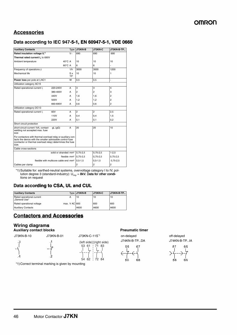
Accessories
Data according to IEC 947-5-1, EN 60947-5-1, VDE 06605-1, EN 60947-5-1, VDE 0660
Data according to CSA, UL and CULrding to CSA, UL and CUL
Contactors and Accessoriestactors and Accessoriesessories
Wiring diagramssAuxiliary contact blocks Pneumatic timer
Auxiliary Contacts Type J73KN-B J73KN-C J73KN-B-TP...
Rated insulation voltage Ui*1
*1) Suitable for: earthed-neutral systems, overvoltage category I to IV, pol-lution degree 3 (standard-industry): Uimp = 8kV. Data for other condi-8kV. Data for other condi-tions on request
V~ 690 690 690
Thermal rated current Ith to 690V
Ambient temperature 40°C A 10 10 10
60°C A 6 6 -
Frequency of operations z 1/h 3000 3000 1200
Mechanical life S x 106
10 10 1
Power loss per pole at Ie/AC1 W 0,5 0,5 -
Utilization category AC15
Rated operational current Ie 220-240V A 3 3 4
380-400V A 2 2 3
440V A 1,6 1,6 2
500V A 1,2 1,2 2
660-690V A 0,6 0,6 2
Utilization category DC13
Rated operational current Ie 60V A 2 2 2,5
110V A 0,4 0,4 1,5
220V A 0,1 0,1 0,2
Short circuit protection
short-circuit current 1kA, contact welding not accepted max. fuse size
gL (gG) A 20 20 10
For contactors with thermal overload relay or auxiliary con-tacts the device with the smaller admissible control fuse (contactor or thermal overload relay) determines the fuse size.
Cable cross-sections
solid or stranded mm² 0,75-2,5 0,75-2,5 1-2,5
flexible mm² 0,75-2,5 0,75-2,5 0,75-2,5
flexible with multicore cable end mm² 0,5-1,5 0,5-1,5 0,75-2,5
Cables per clamp 2 2 2
Auxiliary Contacts Type J73KN-B J73KN-C J73KN-B-TP...
Rated operational current„General Use“
A 10 10 10
Rated operational voltage max. V AC 600 600 600
Auxiliary Contacts A600 A600 A600
J73KN-B-10 J73KN-B-01 J73KN-C-11S*1
*1) Correct terminal marking is given by mounting
53 61
54 62
71 83
72 84
(left side) (right side)
on-delayed off-delayed
J74KN-B-TP...DA J74KN-B-TP...IA
Motor Contactor J7KN 47
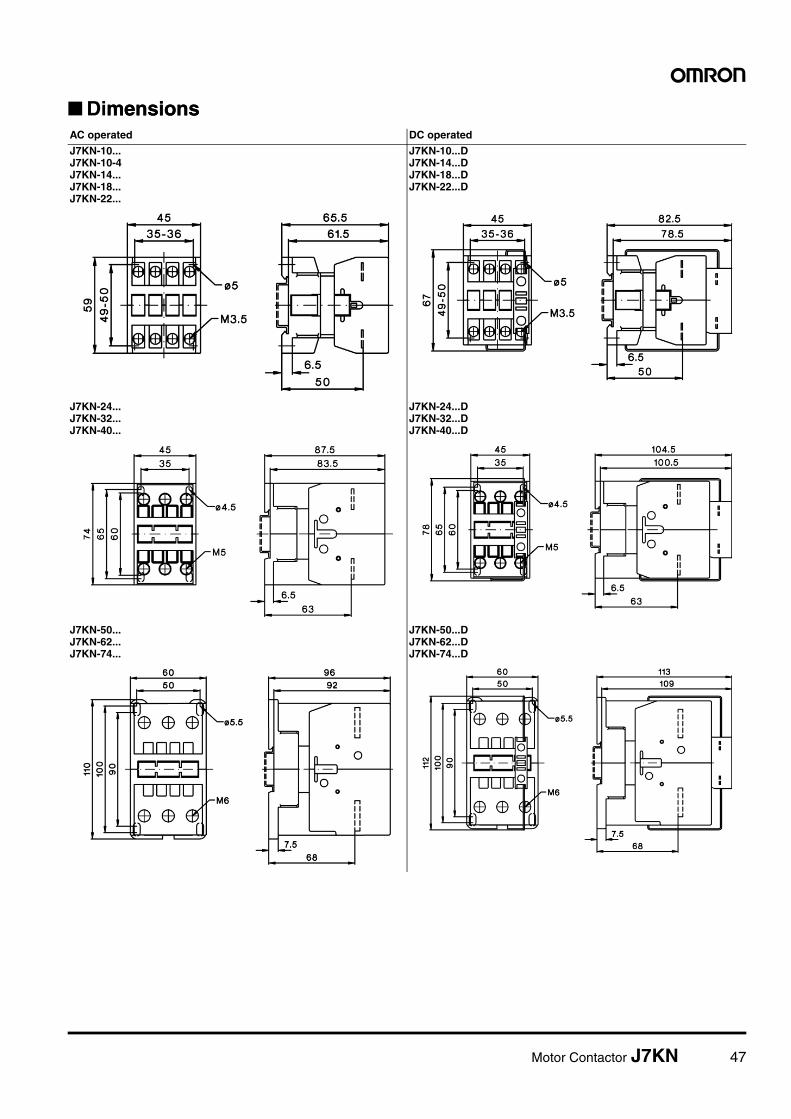
■ DimensionsmensionsAC operated DC operated
J7KN-10...J7KN-10-4J7KN-14...J7KN-18...J7KN-22...
J7KN-10...DJ7KN-14...DJ7KN-18...DJ7KN-22...D
J7KN-24...J7KN-32...J7KN-40...
J7KN-24...DJ7KN-32...DJ7KN-40...D
J7KN-50...J7KN-62...J7KN-74...
J7KN-50...DJ7KN-62...DJ7KN-74...D
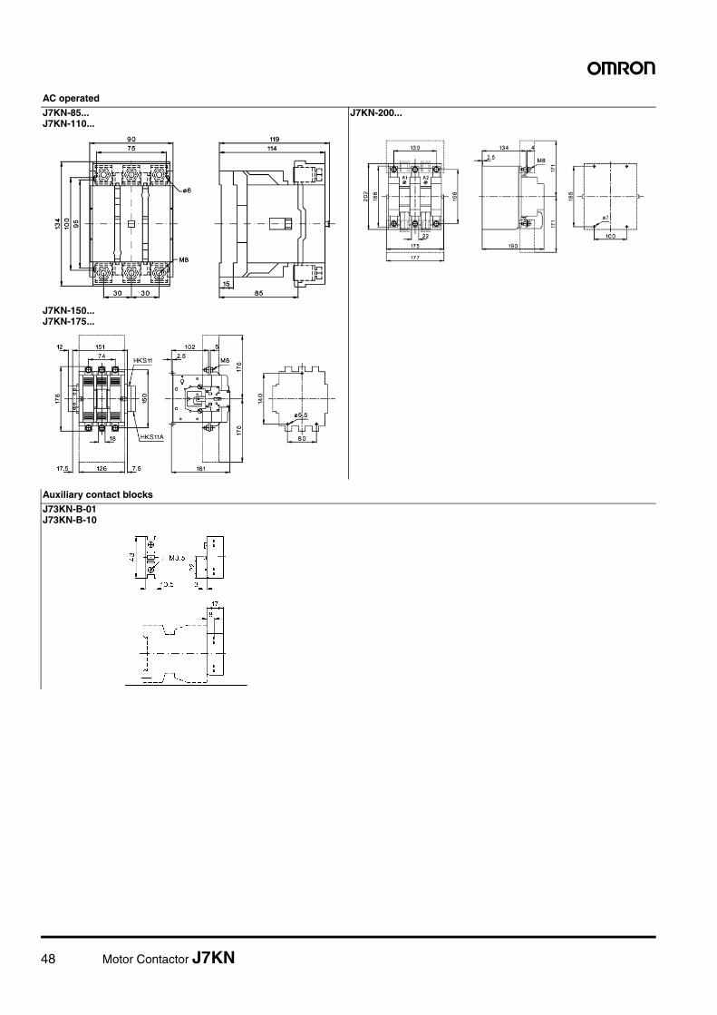
48 Motor Contactor J7KN
AC operated
J7KN-85...J7KN-110...
J7KN-200...
J7KN-150...J7KN-175...
Auxiliary contact blocks
J73KN-B-01J73KN-B-10
Motor Contactor J7KN 49
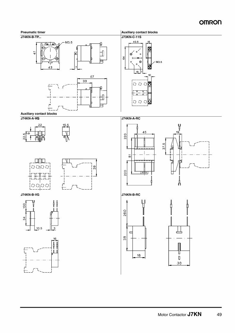
Pneumatic timer Auxiliary contact blocks
J74KN-B-TP... J73KN-C-11S
Auxiliary contact blocks
J74KN-A-VGVG J74KN-A-RC
J74KN-B-VG J74KN-B-RC
50 Motor Contactor J7KN
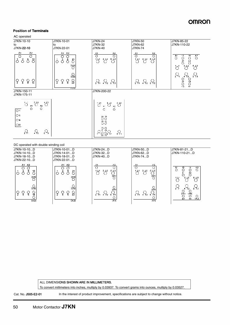
Position of TerminalsTerminals
AC operated
J7KN-10-10 to J7KN-22-1022-10
J7KN-10-01 to J7KN-22-01
J7KN-24J7KN-32J7KN-40
J7KN-50J7KN-62J7KN-74
J7KN-85-22J7KN-110-22
J7KN-150-11J7KN-175-11
J7KN-200-22
DC operated with double winding coil
J7KN-10-10...DJ7KN-14-10...DJ7KN-18-10...DJ7KN-22-10...D
J7KN-10-01...DJ7KN-14-01...DJ7KN-18-01...DJ7KN-22-01...D
J7KN-24...DJ7KN-32...DJ7KN-40...D
J7KN-50...DJ7KN-62...DJ7KN-74...D
J7KN-81-21...DJ7KN-110-21...D
In the interest of product improvement, specifications are subject to change without notice.
ALL DIMENSIONS SHOWN ARE IN MILLIMETERS.ONS SHOWN ARE IN MILLIMETERS.
To convert millimeters into inches, multiply by 0.03937. To convert grams into ounces, multiply by 0.03527.
Cat. No. J505-E2-01J505-E2-01