Embed Size (px)
Citation preview

Design and Construction Guidance for foul and
surface water sewers offered for adoption
under the Code for adoption agreements for
water and sewerage companies operating
wholly or mainly in England ("the Code")
Approved Version 2.1
25 May 2021

Approved Version Sewerage Sector Guidance Appendix C 2.1 25 May 2021
© 2019 Water UK
Version Control
Version Number Date Change Purpose Author
1.0 25 October 2019 Approved by Ofwat Water UK
2.0 10 March 2020 Change to App C E2.21.1
Water UK
2.1 25 May 2021 Changes to Figs B3,18, 20, 21 and para
B5.2.4(a)
Water UK
Copyright
The contents of this document are subject to copyright and all rights are reserved. No part of this document may be reproduced, stored in a retrieval system or transmitted, in any form or by any means electronic, mechanical, photocopying, recording or otherwise, without the prior written consent of the copyright owner.
© October 2019, May 2021 Water UK

Approved Version Sewerage Sector Guidance Appendix C 2.1 25 May 2021
© 2019 Water UK
Approved Version Sewerage Sector Guidance Appendix C 2.1 25 May 2021
i © 2019 Water UK
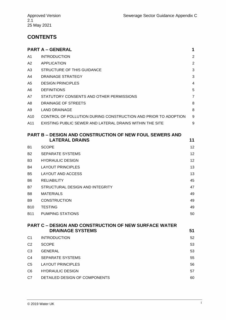
CONTENTS
PART A – GENERAL 1
A1 INTRODUCTION 2
A2 APPLICATION 2
A3 STRUCTURE OF THIS GUIDANCE 3
A4 DRAINAGE STRATEGY 3
A5 DESIGN PRINCIPLES 4
A6 DEFINITIONS 5
A7 STATUTORY CONSENTS AND OTHER PERMISSIONS 7
A8 DRAINAGE OF STREETS 8
A9 LAND DRAINAGE 8
A10 CONTROL OF POLLUTION DURING CONSTRUCTION AND PRIOR TO ADOPTION 9
A11 EXISTING PUBLIC SEWER AND LATERAL DRAINS WITHIN THE SITE 9
PART B – DESIGN AND CONSTRUCTION OF NEW FOUL SEWERS AND LATERAL DRAINS 11
B1 SCOPE 12
B2 SEPARATE SYSTEMS 12
B3 HYDRAULIC DESIGN 12
B4 LAYOUT PRINCIPLES 13
B5 LAYOUT AND ACCESS 13
B6 RELIABILITY 45
B7 STRUCTURAL DESIGN AND INTEGRITY 47
B8 MATERIALS 49
B9 CONSTRUCTION 49
B10 TESTING 49
B11 PUMPING STATIONS 50
PART C – DESIGN AND CONSTRUCTION OF NEW SURFACE WATER DRAINAGE SYSTEMS 51
C1 INTRODUCTION 52
C2 SCOPE 53
C3 GENERAL 53
C4 SEPARATE SYSTEMS 55
C5 LAYOUT PRINCIPLES 56
C6 HYDRAULIC DESIGN 57
C7 DETAILED DESIGN OF COMPONENTS 60

Approved Version Sewerage Sector Guidance Appendix C 2.1 25 May 2021
ii © 2019 Water UK
C8 MATERIALS 70
C9 CONSTRUCTION 71
C10 INSPECTION AND TESTING 71
C11 MAINTENANCE 71
PART D – PUMPING STATIONS 73
D1 INTRODUCTION 74
D2 SCOPE 74
D3 DEFINITIONS 74
D4 GENERAL 74
D5 PROVISION OF PUMPING STATIONS 75
D6 RISING MAINS 83
D7 DESIGN OF PUMPING STATIONS 85
PART E – CIVIL ENGINEERING SPECIFICATION 95
E1 GENERAL 97
E2 MATERIALS 98
E3 EXCAVATION AND BACKFILLING 115
E4 FORMWORK AND CONCRETE 118
E5 CONSTRUCTION OF GRAVITY SEWERS AND RISING MAINS 123
E6 CONSTRUCTION OF MANHOLES, INSPECTION CHAMBERS AND WET WELLS 127
E7 CLEANSING AND TESTING 130
PART F – MECHANICAL AND ELECTRICAL SPECIFICATION FOR SMALL PUMPING STATIONS 135
F1 GENERAL 136
F2 PUMP UNIT SPECIFICATION 136
F3 ELECTRICAL SPECIFICATION 146
F4 VALVE SPECIFICATION 185
APPENDIX I – TYPICAL CONTENTS OF THE CDM HEALTH AND SAFETY FILE 188
APPENDIX II – PUBLICATIONS RELEVANT TO THE DESIGN OF SEWERS, MANHOLES, RISING MAINS AND PUMPING STATIONS 190
APPENDIX III – BRITISH AND OTHER STANDARDS AND CODES OF PRACTICE (TO WHICH REFERENCE IS MADE IN THIS GUIDANCE) 191

Approved Version Sewerage Sector Guidance Appendix C 2.1 25 May 2021
iii © 2019 Water UK
APPENDIX IV - WATER INDUSTRY SPECIFICATIONS/INFORMATION AND GUIDANCE NOTES (TO WHICH REFERENCE IS MADE IN THIS GUIDANCE) 202
APPENDIX V - PARLIAMENTARY ACTS AND REGULATIONS (TO WHICH REFERENCE IS MADE IN THIS GUIDANCE) 203
APPENDIX VI - MISCELLANEOUS PUBLICATIONS (TO WHICH REFERENCE IS MADE IN THIS GUIDANCE) 204
APPENDIX VII - STANDARD SYMBOLS FOR USE ON THE DRAWINGS 208

Approved Version Sewerage Sector Guidance Appendix C 2.1 25 May 2021
1 © 2019 Water UK
PART A – GENERAL
Appendix A

Approved Version Sewerage Sector Guidance Appendix C 2.1 25 May 2021
2 © 2019 Water UK
A1 INTRODUCTION
1. This guidance is for use by developers when planning, designing and constructing foul and surface
water drainage systems (including pumping stations and rising mains) intended for adoption under an
agreement made in accordance with Section 104 of the Water Industry Act 1991. It should be read in
conjunction with the sewerage Sector Guidance published by the sewerage undertakers pursuant to the
Code for adoption agreements for water and sewerage companies operating wholly or mainly in
England ("the Code"), referred to in this document as the Sector Guidance.
2. Any reference to an Act of Parliament or other statutory provision shall include reference to any
amendment, consolidation, modification, extension, re-enactment or replacement of that Act or
provision.
3. At various places in this document, guidance is given on some of the legal terms used. This is
without prejudice, as the true meaning of these terms can only be established by the courts.
A2 APPLICATION
1. Section 104 of the Water Industry Act 1991 (WIA) only applies to the adoption of assets
predominantly used for drainage from buildings or paved areas belonging to buildings. Sewerage
companies do not have a statutory duty to adopt or maintain assets where the main purpose of which is
to deal with drainage of streets (see A8), land drainage runoff, or flows from watercourses or
groundwater (see A9).
2. Where the proposal includes significant technical challenges (e.g., a bespoke in-situ reinforced
concrete structure or a novel design), specialist technical vetting may be necessary by the sewerage
company. Vetting may also be required by the highway authority if it is to be located in a future
adoptable highway. In these cases, the designer is advised to consult with the sewerage company at
the earliest opportunity.
3. This document covers new sewers and lateral drains which are being offered for adoption under
S104 and should not be used as a definitive design manual for other sewerage-related construction
such as rehabilitation, etc. In these cases, the appropriate industry reports, recommendations, guides,
etc., should be used.
4. If pumping stations include any pump unit rated over 30 kW, different specifications may apply and
detailed discussions should be held with the sewerage company at an early stage (see A2.11).
5. The successful design requires the designer to liaise with a variety of stakeholders from the earliest
stages in the design of the development. Further details are given below.
6. A list of minimum requirements of information to support your application is set out in Appendix D of
the Sector Guidance
7. This document applies only to sewerage companies operating wholly or mainly in England.

Approved Version Sewerage Sector Guidance Appendix C 2.1 25 May 2021
3 © 2019 Water UK
8. Compliance with this document is mandatory except in areas identified as being permitted Local
Practices. See Section [2.6] of the Sector Guidance.
9. The developer may decide how much of the system is offered for adoption under the section 104
agreement, provided that the adopted system is a continuous network to an effective discharge point.
10. The local authority as planning authority has a role in approving the design of any surface water
system. In this role, they are required to consult with others, including the lead local flood authority
(LLFA) and, in some circumstances, the Environment Agency and any internal drainage board. The
local authority is also required to clarify the long-term maintenance arrangements for the system.
Further details of this can be found in C1.
A3 STRUCTURE OF THIS GUIDANCE
• Part A gives the scope of the document, definitions and other general guidance.
• Part B gives guidance for the design and construction of new gravity foul sewers and lateral drains.
• Part C gives guidance for the design and construction of new surface water drainage systems.
• Part D gives the industry recommendations for the design and construction of new pumping stations and rising mains.
• Part E gives the Civil Engineering Specification.
• Part F gives the Mechanical and Electrical Specification for pumping stations.
A4 DRAINAGE STRATEGY
1. Developers should engage early with the local authority (both the local planning authority (LPA) and
the lead local flood authority (LLFA)) and the sewerage company to agree a drainage strategy and
maintenance plan (for any size development, i.e., major and minor) prior to making any planning or
S104 Application. Where the local authority is required to consult with other bodies (see A2.11), these
bodies should also be consulted.
2. Surface water drainage proposals should fully explore the surface water hierarchy (see C3.12) and
provide evidence to support alignment with national and local flood risk strategies and policies before
connection to a sewer is considered. If connection to a sewer is required for surface water, sewerage
companies will expect that upon making a S104 Application to adopt a sewer system, a developer will
be able to present robust evidence discounting the discharge of surface water to ground via infiltration
or to a watercourse for all or part of the site and that this evidence has been reviewed by the LLFA and
accepted by the LPA.
3. Where sewers proposed for adoption discharge into a watercourse, developers should consult with
the relevant parties (see A7) regarding permission to discharge. Copies of any information submitted to
these parties, and any design considerations required to meet their requirements, should be included
with the S104 Application.

Approved Version Sewerage Sector Guidance Appendix C 2.1 25 May 2021
4 © 2019 Water UK
4. In some cases, temporary high-water levels in a groundwater body, watercourse or other surface
water body can restrict the discharge of surface water from the adopted system. The design should
take into account the likely frequency and duration of these conditions.
5. A successful drainage strategy should include considerations of future maintenance. Only certain
types of SuDS components are sewers and are therefore adoptable. Early consultation with the
sewerage company is recommended. Where SuDS components are used that are not sewers and
therefore are not adoptable by sewerage companies, the sewerage companies would strongly
encourage the adoption of those components by other bodies that will ensure that they are maintained
in perpetuity. The designer should also consider the interaction of the components and any cross-linked
maintenance requirements.
A5 DESIGN PRINCIPLES
1. Drainage design should be undertaken holistically with other aspects of design (e.g., the site's
topography, geology, street layout, the location of any public open space, soil remediation and
ecological considerations) in an integrated manner. It should, therefore, be considered at the early
stages of design. For larger developments, this should be considered as part of the master planning
phase.
2. During extreme weather, if the capacity of the drainage infrastructure becomes overloaded, water will
flow across the surface of the site. In a holistic design, the layout of the whole development should take
account of the potential risk of flooding to surrounding areas, not just the drainage layouts, and the
effect of any overland flows from adjacent sites. The design should work with the contours of the land to
manage exceedance flows safely.
3. Guidance on holistic design can be found in ‘Building for Life 12’, CIRIA Report C635 ‘Designing for
Exceedance in Urban Drainage - Good Practice’, CIRIA Report C723 ‘Water Sensitive Urban Design in
the UK’ and in CIRIA Report C753 ‘The SuDS Manual’. This applies equally to any system (foul or
surface water) proposed for the site.
4. Developers are reminded of their duty to appoint a principal designer in accordance with the
Construction (Design and Management) Regulations 2015. The principal designer is responsible for all
the duties described in the Regulations.
5. The Regulations also require the principal designer to take into account (in addition to construction
risks) the health and safety aspects over the whole life of the development. The developer's S104
Application must, therefore, include a management and maintenance plan (in addition to the health and
safety file) to demonstrate that the designer has taken the health and safety considerations of future
maintenance into account in preparing the design.
6. A management and maintenance plan should include the following items:
a) the type of maintenance activities that are anticipated;
b) the anticipated frequencies of those activities;

Approved Version Sewerage Sector Guidance Appendix C 2.1 25 May 2021
5 © 2019 Water UK
c) the estimated duration of those activities;
d) any large plant and equipment required to undertake those activities economically;
e) the estimated costs to complete those activities;
f) a site plan showing maintenance areas, access routes and the locations where maintenance
activities are anticipated and
g) a statement describing any secondary function (e.g., recreation area) above or within the
SuDS component, and details describing how this function is to be managed and by whom.
7. Further details of the required contents of the health and safety file can be found in Appendix I.
8. The principal designer is reminded that any part of the drainage system could be considered to be a
workplace, in accordance with the Regulations.
A6 DEFINITIONS
In this guidance:
1. "access point" means provision to access a sewer or drain for testing, inspection, maintenance and
removal of debris, and includes any manhole or inspection chamber.
2. "adoption" in general terms means the process whereby assets are vested in the sewerage
company or another body and subsequently maintained by that body at its expense.
3. "Code" means the Code for adoption agreements for water and sewerage companies operating
wholly or mainly in England, published by Ofwat in August 2018, as that document is amended from
time to time.
4. "curtilage" means the area of land around a building, or group of buildings, which is for the private
use of the occupants of the buildings.
Its meaning has been explored in case law, for example:
a) detached, semi-detached and terraced houses can each be considered as a separate
curtilage;
b) where a building contains a number of flats, the whole block of flats can be considered to be a
single curtilage;
c) separate commercial properties sited on land privately-owned by a single body (e.g., a
shopping centre, airport terminal, retail park, etc.) can be considered as a single curtilage if
the commercial properties share the site access and facilities.
5. "demarcation chamber" means an inspection chamber placed near the boundary of the property at
the upstream end of the lateral drain.
6. "developer" means a Developer as defined in the Code.

Approved Version Sewerage Sector Guidance Appendix C 2.1 25 May 2021
6 © 2019 Water UK
7. "drain" means a drain used for the drainage of one building or of any buildings or yards appurtenant
to buildings within the same curtilage (see Water Industry Act 1991 Section 219).
8. "effective discharge point" means point of discharge which has been specifically designed to
discharge the foul sewage or surface water, and for which there is a legal right to discharge. This can
be to another sewer or (provided that there is a legal right to discharge) to a natural watercourse, an
area of land or an infiltration drainage component (see A7).
9. "freeboard" means the distance between the design water level and the top of a structure, provided
as a precautionary safety measure against early system failure.
10. "inspection chamber" means a chamber on a drain or sewer with working space at ground level
only, used to introduce equipment for testing, inspection and maintenance.
11. "lateral drain" means that part of the drain which is between the point of demarcation (e.g.,
demarcation chamber), or the boundary of the property it serves, and the sewer.
Guidance on whether pipes are lateral drains can be found ‘Guide to Transfer of Private Sewers
Regulations 2011’ and this is also provides guidance on whether pipes are potentially sewers or lateral
drains.
12. "local authority" includes an authority acting in any capacity this can include a local planning
authority (LPA) and lead local flood authority (LLFA). Further information on the relevant roles of local
authorities can be found in Part C.
13. "manhole" means a chamber with working space at drain/sewer level used for entry of personnel
and equipment.
14. "pavement" means a paved construction (including a yard or highway) and any underlying
structure.
15. "pavement structure" comprises the sub-base and any membrane below it, together with the
layers above, including, base course, surface course, binder course, laying course or paving layer.
16. "public sewer" means a sewer for the time being vested in a sewerage company in its capacity as
sewerage undertaker (see Water Industry Act 1991 Section219).
17. "raised reservoir" means a reservoir designed to hold, or capable of holding, water above the
natural level of any part of the land adjoining the reservoir (see Reservoirs Act 1975 Section 1).
18. "rising main" means a sewer through which foul sewage and/or surface water is pumped.
19. "sewer" includes all sewers and drains (not being drains within the meaning above) which are used
for the drainage of buildings and yards appurtenant to buildings in more than one curtilage (see A6.4)
(see Water Industry Act 1991 Section 219).

Approved Version Sewerage Sector Guidance Appendix C 2.1 25 May 2021
7 © 2019 Water UK
Guidance on whether pipes are sewers can be found in a ‘Guide to Transfer of Private Sewers
Regulations 2011’ and this is also applicable to determine whether SuDS components are potentially
sewers or lateral drains (see A6.11).
20. "Sewerage Sector Guidance" means the document so entitled which is approved by Ofwat under
the Code.
21. “street” means the whole or any part of any of the following, irrespective of whether it is a
thoroughfare:
a) any highway, road, lane, footway, alley or passage;
b) any square or court; and
c) any land laid out as a way whether it is for the time being formed as a way or not.
Where a street passes over a bridge or through a tunnel, the street includes that bridge or tunnel (see
New Roads and Street Works Act 1991 Section 48).
22. "surface component" means a component of a surface water drainage system that is not buried
underground.
23. "vesting" means the formal transfer of ownership and responsibility of sewers from the developer to
the sewerage company or other body.
24. "sewerage company" means a sewerage undertaker appointed under the Water Industry Act 1991
and includes any agent appointed to act on its behalf.
25. "works" means the prospectively adoptable drainage systems described in the Section 104
Agreement.
26. "yard" means a paved area including a driveway, patio, hard standing or footpath.
A7 STATUTORY CONSENTS AND OTHER PERMISSIONS
1. The developer should, in liaison with the sewerage company, obtain all necessary statutory consents
and other permissions before the agreement is signed. Relevant bodies can include:
a) consent of the pollution control authority (the Environment Agency in England) for emergency
overflows and contaminated waters;
b) permission of the navigation authority (usually the Canal and River Trust) to discharge to
waters under their control;
c) permission of riparian owners will be required to discharge to a watercourse;
d) landowner’s permission to discharge water onto land;
e) landowner’s permission for construction of any part of the drainage system on third-party land;
f) the Crown, Network Rail, airport authorities, or MOD, etc., where special permission may be
required for land owned by them;

Approved Version Sewerage Sector Guidance Appendix C 2.1 25 May 2021
8 © 2019 Water UK
g) the land drainage authority (Environment Agency, for main rivers, local land drainage
authorities for non-main rivers) for consent for the construction of outfalls or works within
close proximity to a watercourse;
h) English Nature where any of the works will affect an environmentally-designated site (e.g.,
SSSI) or could affect protected species;
i) the planning approval for the site from the Local Planning Authority.
2. Throughout any pre-application discussions (see Appendix D of the Sector Guidance) , the developer
should be able to show progress in discussions with the relevant bodies and before formally making the
S104 Application they should be able to show evidence that any conditions will not affect the design of
the system..
3. Individual sewerage company requirements for easements for surface water discharges to
watercourse, bodies of water, sewers within third party land and sewers which may form part of another
feature are permitted as ‘Local Practices’ under the Sector Guidance. Details of these requirements
are published on sewerage company websites.
A8 DRAINAGE OF STREETS
1. The sewerage company is not obliged to accept runoff from newly-constructed streets into the public
sewer system. The developer should note that acceptance of this runoff into the works and, ultimately,
the public sewer system, is only by agreement, which will not be unreasonably withheld.
2. Where the developer wishes to connect drainage from streets to a surface water sewer or a
combined sewer, they should discuss this with the sewerage company as early as possible as the
specific consent of the sewerage company will be required in advance. The connection of drainage
from streets to a foul sewer will not be permitted.
3. The connection of runoff from publicly-adoptable highways to a public sewer is regulated by the
Water Industry Act 1991 Section 115. Some sewerage companies may have a separate formal
agreement for such discharges. This agreement is formally between the highway authority and the
sewerage company but, prior to adoption of the highway, the developer as owner is party to the
agreement. Section 115 also deals with connections of surface water to a highway drainage system.
4. It is particularly important to have an agreement in place which confirms the area of highway being
drained to the public sewer, especially where there are issues regarding capacity, connection to a
combined sewer or where only highway drainage is to be connected to the public sewer.
A9 LAND DRAINAGE
1. Sewerage companies have no duty to accept land drainage runoff, flows from natural watercourses
or groundwater to the public sewer system, and this is not normally permitted.
Approved Version Sewerage Sector Guidance Appendix C 2.1 25 May 2021
9 © 2019 Water UK
A10 CONTROL OF POLLUTION DURING CONSTRUCTION AND PRIOR TO ADOPTION
1. The developer should maintain the integrity of separate surface water sewer systems and is
responsible for any blockages, pumping station breakdown, cross-connections, etc., and any impact
(e.g., flooding or pollution, etc.) up to the time the sewers are adopted.
2. The developer should include in their S104 Application a plan for approval by the sewerage company
to demonstrate how sediment and other debris will be managed to avoid any sediment or debris being
discharged into the proposed drainage system, any public sewer or a surface water body. The
developer should comply with this plan at all times during construction and during any maintenance
carried out prior to adoption.
A11 EXISTING PUBLIC SEWER AND LATERAL DRAINS WITHIN THE SITE
1. The developer should note that there could be existing public sewers and lateral drains within the
site. Due to their nature, historic mapping of these features, particularly former private sewers
transferred under Water Industry Act 1991 Section 105A, may not be available and the developer is
encouraged to investigate the location and interconnection of any existing drainage assets on site.
2. Where the developer proposes to construct buildings over or near existing public sewers or lateral
drains, they should consult the sewerage company at the earliest opportunity. In some cases, the
sewer or lateral drain may need to be diverted.
3. As soon as a diversion of an existing public sewer is envisaged as part of the development, the
developer should contact the sewerage company to agree if the diversion is feasible. A separate
application may be required under Section 185 of the Water Industry Act 1991. It should be noted that
since the private sewers transfer, many sewers that were previously private are now public sewers.
4. Where the developer wishes the sewerage company to abandon existing public sewers and lateral
drains within their site in accordance with Section 116 of the Water Industry Act 1991, they should
contact the sewerage company to agree the required arrangements.
5. Where any works are to be carried out in proximity to existing sewers or lateral drains, appropriate
protection methods and mitigation plans should be agreed with the sewerage company to protect the
assets. These details should also be retained within the health and safety documents.

Approved Version Sewerage Sector Guidance Appendix C 2.1 25 May 2021
10 © 2019 Water UK

Approved Version Sewerage Sector Guidance Appendix C 2.1 25 May 2021
11 © 2019 Water UK
PART B – DESIGN AND CONSTRUCTION OF NEW FOUL SEWERS AND LATERAL DRAINS
Appendix B
Approved Version Sewerage Sector Guidance Appendix C 2.1 25 May 2021
12 © 2019 Water UK
B1 SCOPE
1. This Part gives guidance on the design and construction of gravity, foul and lateral drains, and
sewers. For guidance on surface water sewer systems see Part C, and for guidance on sewage
pumping stations see Part D.
B2 SEPARATE SYSTEMS
1. Separate foul and surface water systems should be provided.
2. If sewers are to discharge into an existing combined (single pipe) sewer system, the separate foul
and surface water sewers should be combined at locations immediately upstream of the point where
they discharge into the existing combined sewer system. The levels should be arranged to minimise the
risk of foul sewage entering into the surface water system.
3. Natural watercourses, land drainage and groundwater are not permitted to be directly or indirectly
connected to the public foul sewer system (see A9).
B3 HYDRAULIC DESIGN
B3.1 Foul Sewers and Lateral Drains
1. The peak design flow rates for dwellings should, at the discretion of the designer, be either:
a) calculated in accordance with BS EN 12056-2 System II (this method is recommended for this
application in BS EN 16933-2); or
b) 4000 litres per dwelling per day (0.05 litres per second per dwelling). Note: This is a design
peak flow rate not a daily average water usage, and represents the peak flow rate from a
number of appliances. Reducing daily water usage does not necessarily reduce the peak flow
rate.
2. Design flows for industrial and commercial developments can contain two elements: domestic flows
(flows from toilets and kitchens, etc.) and trade effluent flow (wastewater from industrial processes1).
The total peak design flow is the sum of the domestic design flow and the trade effluent design flow.
a) The domestic design flow should be calculated in accordance with BS EN 12056-2System II
(see also BS EN 16933-2) or, in the absence of appropriate information, 0.6 litres per second
per hectare of developable land;
b) The trade effluent design flow should be based on a metered discharge from premises similar
to that proposed, or assumed as 0.5 litres per second per hectare for normal industry and
1 litre per second per hectare for wet industry. Where the proportion of wet industry is
unknown, an average flow of 0.7 litres per second per hectare should be used.
1 Developers are reminded that the occupier of the building will be required to make a separate application to
discharge any trade effluent flows.

Approved Version Sewerage Sector Guidance Appendix C 2.1 25 May 2021
13 © 2019 Water UK
3. The Colebrook-White hydraulic roughness value (ks) for foul gravity sewer design should be 1.5 mm
for all sewer material types.
4. Foul sewers and lateral drains should be designed to run at no more than 75% of pipe full conditions.
5. The minimum pipe sizes specified in B6 may provide more capacity than the peak flow rates
determined from B3.1 or B3.2.
B3.2 Protection Against Flooding
1. In designing the site sewerage and layout, developers should also demonstrate flow paths and the
potential effects of flooding resulting from blockages, pumping station failure or surcharging in
downstream combined sewers, by checking the ground levels around the likely points that flow would
flood from the system to identify the flood routes.
B4 LAYOUT PRINCIPLES
1. The layout of the development can affect the existing drainage patterns and flood risk. The layout of
the development, including landscaping and vegetation, should take account of the impact it may have
on the layout of drains and sewers. (see B5.1). This should be addressed at the master planning stage.
2. Sewers and lateral drains should be laid in straight lines in both the vertical alignment (profile) and
horizontal alignment (plan) unless agreed with the sewerage company.
3. The layout should ensure that sufficient access points are located so that they are accessible and
apparent to the sewerage company at all times to provide access to every sewer and lateral drain (see
B5.2).
4. Sewers and lateral drains should be located so that if there is a structural failure of the drain, sewer
or rising main, or an excavation is carried out to repair the drain, sewer or rising main, the integrity of
adjacent buildings or other infrastructure is not impaired. (see B5.1.3 to B5.1.6 and B5.1.8 to B5.1.9).
B5 LAYOUT AND ACCESS
B5.1 Layout
1. As far as practicable, sewers and lateral drains should be laid in highways or public open space
where they are reasonably accessible and visible. Sewers should not be laid in enclosed private land.
Where this is not practicable, sewers and lateral drains with a nominal internal diameter of 150 mm or
less may be laid:
a) in shared rear yards or parking areas or other shared areas to which all the properties served
by the sewers have right of access; or where this is not reasonably practicable
b) where the drain or sewer serves ten properties or less, in unfenced gardens; or where this is
not reasonably practicable
c) in fenced private areas provided that the sewer is kept as far as is practicable from any point
on a building where a future extension is likely.

Approved Version Sewerage Sector Guidance Appendix C 2.1 25 May 2021
14 © 2019 Water UK
2. Access points on sewers and lateral drains should not be laid in enclosed private land. Where this is
not practicable, access points of sewers and lateral drains may be constructed:
a) in shared rear yards or parking areas, provided there is free access at all times;
b) in enclosed shared private areas provided that all those properties served by the sewers have
right of access to the area at all times. Access control systems should include provision for
access by the sewerage company;
c) where the drain or sewer serves ten properties or less, in unfenced gardens; or
d) on sewers serving no more than two properties, provided that access is also possible from the
other property by another access point.
3. The external face of any new sewer or lateral drain should be at least 1.2 m from any building or
structure (e.g., a wall), or a distance equivalent to the depth of the sewer below the foundation,
whichever is greater; except that a sewer or lateral drain with a nominal internal diameter of 150 mm or
less, with an invert level at least 150 mm above the base of the foundation and no more than 1100 mm
deep, and should be greater than 100 mm from the foundations (see Figure B 1).
4. Where it is not possible to comply with B5.1.3 because another building/structure is in such close
proximity that there are no permitted locations, new sewers or lateral drains may be located between
buildings or structures provided that:
a) there is at least 900 mm separating the buildings or structures where a single sewer or lateral
drain is proposed and 1100 mm where dual systems are proposed;
b) the depth of the invert of the sewer or lateral drain below the ground level is no greater than
the distance between the buildings or structures;
c) the sewers or lateral drains have a nominal internal diameter of 150 mm or less;
d) the sewers or lateral drains have an invert level at least 150 mm above the base of the
highest of the foundations of the two buildings;
e) there is at least 350 mm cover above the pipe; and
f) there is at least 100 mm between the pipe wall and the foundations (see Figure B 2).
5. For the purposes of B5.1.3 and B5.1.4, the foundation level of the building or structure with piled
foundations should be taken as:
a) for friction piles (or piles with a combination of friction and end bearing), from the underside of
the capping beam; or
b) for end bearing piles (with no allowance for side friction), the base of the pile.
Note: In B5.1.1, B5.1.3 and B5.1.4, the recommendations are intended to allow sufficient working space
for hand excavation in proximity to the building or structure if repair is necessary in the future.
6. Foul sewers and lateral drains should not be constructed under any building, or any structure except
that they may cross under a boundary wall not greater than 1.8 m high (see B7.4).
7. The minimum depth of cover to the crown of gravity pipes without protection should be as follows:

Approved Version Sewerage Sector Guidance Appendix C 2.1 25 May 2021
15 © 2019 Water UK
a) domestic gardens and pathways without any possibility of vehicular access, 0.35 m;
b) domestic driveways, parking areas and yards with height restrictions to prevent entry by
vehicles with a gross vehicle weight in excess of 7.5 tonnes, 0.5 m;
c) domestic driveways, parking areas and narrow streets without footways (e.g., mews
developments) with limited access for vehicles with a gross vehicle weight in excess of
7.5 tonnes, 0.9 m;
d) agricultural land and public open space, 0.9 m;
e) other highways and parking areas with unrestricted access to vehicles with a gross vehicle
weight in excess of 7.5 tonnes, 1.2 m.
8. Sewers and lateral drains may be laid through arches and other external openings through buildings
or structures provided that they are laid as near to the centre of the opening as possible and:
a) for vehicular entries with a minimum width of 4.0 m and minimum height of arch above ground
level of 2.1 m, the maximum nominal internal diameter of the pipe should be 225 mm with a
maximum depth to invert of the pipe of 2.0 m and the invert should be at least 150 mm above
the foundation level; or
b) for pedestrian access with a minimum width of 0.9 m and minimum height of 2.0 m, the
maximum nominal internal diameter of the pipe should be 100 mm and should comply with
B5.1.4.
9. Sewers or lateral drains may pass through an opening in a property boundary wall provided that
there is an arch or lintelled opening to give at least 50 mm space around the pipe (see B5.1.6).

Approved Version Sewerage Sector Guidance Appendix C 2.1 25 May 2021
16 © 2019 Water UK
Figure B 1 Illustration of the permitted locations of adoptable sewers and
lateral drains in proximity to buildings

Approved Version Sewerage Sector Guidance Appendix C 2.1 25 May 2021
17 © 2019 Water UK
Figure B 2 Illustration of the permitted location of small diameter adoptable sewers and
lateral drains between buildings

Approved Version Sewerage Sector Guidance Appendix C 2.1 25 May 2021
18 © 2019 Water UK
10. The design of landscaping should be undertaken at the same time as the design of the lateral
drains and sewers so that the impact of tree roots on sewers and drains can be considered. A sewer or
lateral drain should not be located closer to trees/bushes/shrubs than the canopy width at mature
height, except where special protection measures are provided, in accordance with B7.6. A tree should
not be planted directly over sewers or where excavation onto the sewer would require removal of the
tree. The following shallow rooting shrubs are generally suitable for planting close to sewers and lateral
drains:
• Berberis candidula; (paleleaf barberry)
• Berberis julianae; (wintergreen barberry)
• Ceanothus burkwoodii; (Californian lilac ‘Burkwoodii’)
• Cotoneaster dammeri; (bearberry cotoneaster)
• Cotoneaster skogholm; (Cotoneaster x suecicus, ‘Skogholm’)
• Cytisus varieties or Sarothamnus; ((common or Scotch) broom)
• Euonymus japonicus; (Japanese spindle)
• Euonymus radicans; Variety of Euonymus (fortune’s spindle or winter creeper)
• Mahonia varieties; can be included in the genus Berberis, most common name is
M. aquifolium (Oregon grape)
• Potentilla varieties; most varieties are types of cinquefoil. Also includes common tormentil,
silverweed and barren strawberry
• Skimmia japonica; (Skimmia)
• Spiraea japonica; (Japanese spirea or Japanese meadowsweet)
• Veronica varieties; (Speedwell)
• Viburnum davidii; (David viburnum)
• Viburnum tinus; (Lauristinus)
11. To minimise the risk of root damage, tree planting should provide good growing conditions.
Guidance can be found in ‘Trees in Hard Landscapes: A Guide for Delivery’.
12. When constructed along the line of a highway, the sewer should be laid in the carriageway and,
where practicable, at least 1m from the kerbline. The external faces of manholes (including any
concrete surround) should be at least 0.5 m from the kerbline. This is to allow any subsequent
excavation for a new connection or a repair to be made without interfering with other services sited in
the footway.
13. Where it is proposed to lay pipes in third-party land, agreement should be obtained from the owner
of the land surface as to acceptable levels of predicted settlement, prior to the construction. The
construction techniques should be selected to ensure that the maximum settlement is within the agreed
limits.
14. Where foul sewers are laid under some types of SuDs components (e.g., a swale or a rill), this can
require decommissioning and reconstruction of the SuDS component if excavation is required to repair
the foul sewer. The layout of both foul sewers and surface water drainage should minimise the length of
foul sewer under SuDs components, for example, by ensuring that any crossings are at as near as

Approved Version Sewerage Sector Guidance Appendix C 2.1 25 May 2021
19 © 2019 Water UK
possible to a right angle and are positioned under narrow SuDS components. Foul sewers should not
be laid under infiltration components. If necessary a short section of an infiltration component may be
modified so that the foul sewer passes through a section where no infiltration takes place.
15. BS EN 752 provides further detail on the design of sewer systems including layout.
B5.2 Access
1. Access points, should be located so that they are accessible and apparent to the sewerage company
at all times for use. They should avoid rear gardens or enclosed locations. Additional access points
may be provided in other locations, as long as access is provided to the system from other access
points, in accordance with the recommendations in B5.2.2 to B5.2.30.
2. Access points, and any inlets to drains or sewers, should be located so as to minimise the risk of
damage to buildings or other critical infrastructure in the event of sewer flooding.
3. Access points and sewers should be sited with due regard to public utility services. An access point
should be built:
a) at every change of alignment or gradient (though this does not exclude the use of a backdrop
at a manhole in accordance with B5.2.27);
b) at the head of all branches;
c) at every junction of two or more public sewers;
d) wherever there is a change in the size of the sewer;
e) at every junction of a public sewer with another sewer serving three or more properties; or
f) at or within 1 m of the property boundary at the upstream end of each lateral drain (preferably
inside the property boundary).
4. Manholes should be provided as the means of access to a pipe where:
a) the depth from cover level to soffit is greater than 3 m; or
b) where the diameter of the largest sewer is greater than or equal to 450 mm DN/ID;
c) where the chamber contains equipment (e.g., penstock or flow control device) that will require
maintenance; or
d) where the chamber serves more than ten properties.
In other locations specified in B5.2.3, the access point may be an inspection chamber.
5. The flow diagram in Figure B3, used in conjunction with the access structure standard details will
ensure that the sewerage system meets the required safety, operational and sustainability standards.
Each junction, change of direction or change of status, is described here as a node. Unless otherwise
required in accordance with B5.2.6, no access is required at a node if it connects less than three
properties and there already is, or will be, sufficient access to carry out sewer maintenance.
6. Where access to a pipe is provided through an inspection chamber, no part of the pipe should be
more than 22.5 m from the adjacent inspection chamber (i.e., the distance between adjacent inspection

Approved Version Sewerage Sector Guidance Appendix C 2.1 25 May 2021
20 © 2019 Water UK
chambers should be no more than 45 m). Where access to a pipe is provided through a manhole, no
part of the pipe should be more than 45 m from the adjacent manhole (i.e., the distance between
adjacent manholes should be no more than 90 m). Where the nearest adjacent node to a manhole is an
inspection chamber, they should be no more than 45 m apart.
7. Manholes should be designed for safe access and egress. The minimum clear opening into any
manhole less than or equal to 3 metres deep to the soffit of the lowest outgoing pipe should be 600 mm
x 600 mm.
8. Inspection chambers should be designed to afford reasonable access for equipment to carry out
testing, inspection and maintenance activities. Inspection chambers should be designed for personnel
working at ground level.
9. Any pipe, and associated access upstream of the point of demarcation, is a private drain and should
be constructed in accordance with the Building Regulations.
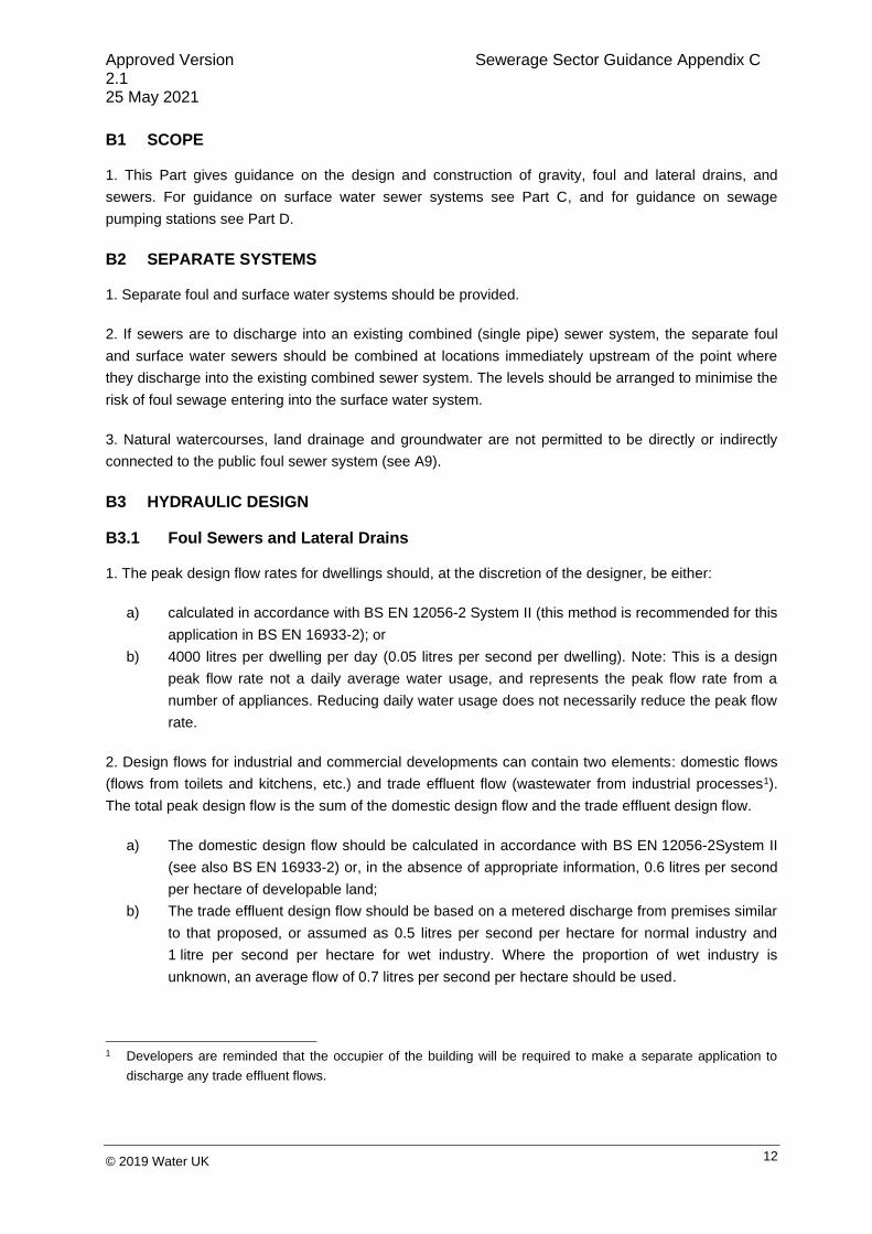
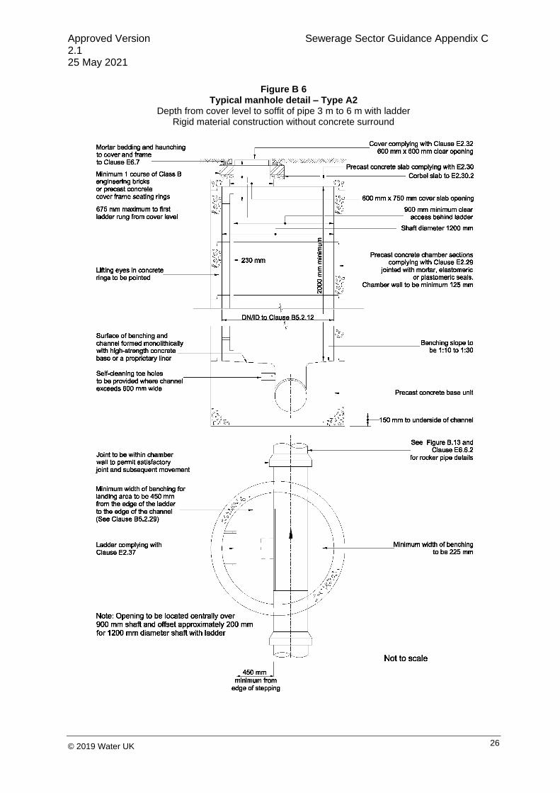
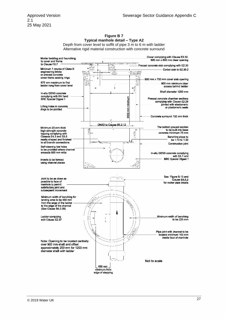
10. Figure B 4 to Figure B 17 show typical details of manholes for a variety of depths from cover level to
soffit of pipe up to 6 m, including backdrops. No significant departure from these dimensions should be
made without approval by the sewerage company.
11. In exceptional cases, where access is required at a greater depth than 6 m, the details should be
agreed in advance with the sewerage company.
12. Minimum manhole diameters for Type A, B and C manholes should be in accordance with Table B
1. The minimum diameter should be increased, as necessary, to provide the minimum benching
dimensions specified in Figures Figure B 4 to Figure B 12.
Table B 1 Manhole diameters
Nominal Internal Diameter of Largest Pipe in Manhole (mm)
Minimum Nominal Internal Dimension of Manhole (mm)
Less than 375 1200
375 – 450 1350
500 – 700 1500
750 – 900 1800
Greater than 900 Pipe diameter + 900

Approved Version Sewerage Sector Guidance Appendix C 2.1 25 May 2021
21 © 2019 Water UK
Figure B 3 Access type selection
All depths are from cover level to the soffit of highest outgoing pipe
No
Yes
Yes
No
Yes
No
Yes
Start
No access
required at the
node
Site-specific
engineered
solution
Type A Access
(3-6m)
Type B Access
(< 3m)
Type D Access
(non-entry)
Is node > 6m deep
Is node > 3m deep
Does node serve
> 3 properties
No
Yes
Yes
Is outgoing pipe
≥ DN/ID450
Type C Access
(< 1.5m)
Yes
No
Type E Access
(non-entry)
Does node serve
> 10 propertiesIs node > 1.5m deep
No
Site-specific
engineered
solution
Yes
No
Is node > 2m deep
Does node
connect > 2
properties
Will access other-
wise be available No
No
Yes
Yes

Approved Version Sewerage Sector Guidance Appendix C 2.1 25 May 2021
22 © 2019 Water UK
13. The height of a Type A manhole (benching to slab soffit) should normally be in excess of 2000 mm.
When this is impracticable, Type B manholes are preferred, subject to an absolute minimum height
(benching to slab soffit) of 900 mm.
14. The internal dimensions quoted above are considered to be the minimum. Where two or more pipes
enter the manhole, the internal dimensions should be increased, where necessary, to accommodate
the minimum width of benching. Pipes of different diameters entering manholes should be installed with
soffits at the same level.
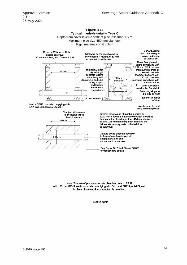
15. The dimensions of Type C manholes should be as shown in Figure B 14 or Figure B 15.
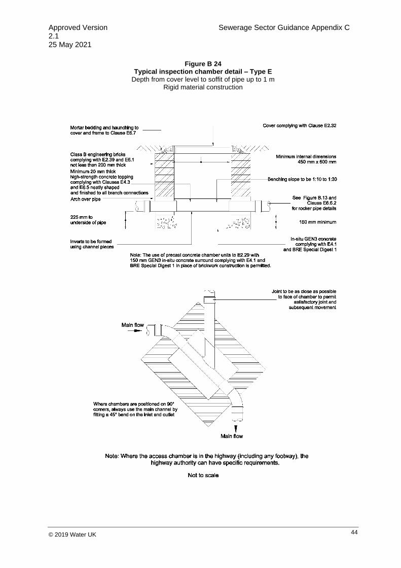
16. Figure B 18 to Figure B 25 show typical details of Type D and Type E inspection chambers. No
significant departure from these should be made without approval by the sewerage company.
17. The design of special manholes and other structures should be agreed with the sewerage
company.
18. "In-fill" type covers should not be used unless the developer can demonstrate that the cover can be
safely lifted by two persons using standard lifting keys and that the lateral forces applied by the in-fill
will not deform the cover or frame, causing the cover to become stuck in the frame. Where a cover is
located in an area of block paving, the minimum frame depth should be 150 mm.
19. Covers for manholes and inspection chambers should be in accordance with E2.32 of the Civil
Engineering Specification.
20. Where covers are sited in NRSWA Road Types 0, 1, 2 or 3, the frames of manhole covers should
be bedded using a mortar complying with the requirements of the Design Manual for Roads and
Bridges 4.2 Part 5 HA/104/09 (e.g., a suitable polyester resin bedding mortar).
21. In situations where traffic loading is anticipated to be heavier (e.g., in industrial developments where
large numbers of HGV movements are expected) than would occur on a typical residential estate
distributor road, a cover with a higher specification than BS EN 124 D400 should be used. This should
comprise either a Class E600 cover or a D400 of a type that has been assessed and approved by the
sewerage company as having sufficient additional ruggedness to ensure durability.
22. Unless the chamber is designed to withstand the vertical load acting on it, a precast concrete slab
or in-situ concrete slab, should be provided, to act as a collar to support the cover and frame. The collar
should be separate from the chamber to ensure the loading from the cover and frame is not transferred
to the chamber. The collar itself and the material below the collar should be designed to accommodate
and distribute the loads acting on the collar and into the substrate without resulting in settlement.
23. The first manhole upstream from the connection to the (existing) public sewer should, when
constructed, be fitted with a temporary screen in order to prevent debris entering the public sewer. The
screen should not be removed until immediately prior to the occupation of premises to be served by the
sewer.

Approved Version Sewerage Sector Guidance Appendix C 2.1 25 May 2021
23 © 2019 Water UK
24. Rocker pipes should be provided at entry to, and exits from, manholes when rigid pipes are used.
Their length should be as shown in Table E 13 (see E6.6).
25. Where pipes serving a total of three properties or less connect to a pipe that has a nominal internal
diameter less than or equal to 150 mm, the branch connections should be set so that the soffits of all
the pipes are at the same level. In all other cases, branch connections should be set with the soffit
levels no lower than that of the main pipe and with the invert level of the branch connection at least
50 mm above the invert of the main pipe.
26. The main channel should extend the whole length of the chamber, comprising a half-round section
plus vertical benching from the top edge of the half round section to a height of not less than that of the
soffit of the outlet, where it should be rounded off and sloped upwards to meet the wall of the chamber.
The channel should not bend by more than 90 degrees (including any connecting pipe. Connecting
pipes should be constructed from swept channels (see Figure B 13).
27. Steeper gradients are preferred to the use of backdrops. Where pre-formed manhole or inspection
chamber bases are used, the angular displacement at the joints between the manhole base and the
pipe comply with the requirements of E5.9.4. Where steeper gradients are impractical, backdrops
should be constructed at manholes as shown in Figure B 16 or Figure B 17. Ramped backdrops should
be used for manholes rather than vertical backdrops.
28. Where step rungs and ladders are to be used, the distance from the top rung to the surface should
be a maximum of 675 mm (see E6.7) with a minimum of one course of brickwork. Where ladders are to
be used, they should be positioned relative to the access so that the minimum clear opening is not
obstructed.
29. At the foot of each ladder or set of step rungs, a minimum of 450 mm landing area should be
provided from the outer edge of the step or rung. This may consist of:
a) a single area adjacent to the foot of the ladder or steps; or
b) where the channel is no more than DN450, one area of at least 225 mm adjacent to the foot
of the ladder or steps with the remainder on the other side of the channel.
30. The minimum dimensions of inspection chambers are determined by the entry radius needed by the
equipment as it passes into the pipe (see Figure B 25). The clear opening should, therefore, have a
minimum diameter greater than 50% of the internal diameter of chamber, subject to a minimum of
90 mm.
31. BS EN 752 provides further detail on the design of sewer systems including provision of access.

Approved Version Sewerage Sector Guidance Appendix C 2.1 25 May 2021
24 © 2019 Water UK
Figure B 4 Typical manhole detail – Type A1
Depth from cover level to soffit of pipe 3 m to 6 m with ladder and reducing slab Rigid material construction without concrete surround

Approved Version Sewerage Sector Guidance Appendix C 2.1 25 May 2021
25 © 2019 Water UK
Figure B 5 Typical manhole detail – Type A1
Depth from cover level to soffit of pipe 3 m to 6 m with ladder and reducing slab Rigid material construction with concrete surround
Approved Version Sewerage Sector Guidance Appendix C 2.1 25 May 2021
26 © 2019 Water UK
Figure B 6 Typical manhole detail – Type A2
Depth from cover level to soffit of pipe 3 m to 6 m with ladder Rigid material construction without concrete surround
Approved Version Sewerage Sector Guidance Appendix C 2.1 25 May 2021
27 © 2019 Water UK
Figure B 7 Typical manhole detail – Type A2
Depth from cover level to soffit of pipe 3 m to 6 m with ladder Alternative rigid material construction with concrete surround

Approved Version Sewerage Sector Guidance Appendix C 2.1 25 May 2021
28 © 2019 Water UK
Figure B 8 Typical manhole detail – Type A2
Depth from cover level to soffit of pipe 3 m to 6 m with ladder Flexible material construction
Approved Version Sewerage Sector Guidance Appendix C 2.1 25 May 2021
29 © 2019 Water UK
Figure B 9 Typical manhole detail – Type B
Depth from cover level to soffit of pipe 1.5 m to 3 m Rigid material construction without concrete surround

Approved Version Sewerage Sector Guidance Appendix C 2.1 25 May 2021
30 © 2019 Water UK
Figure B 10 Typical manhole detail – Type B
Depth from cover level to soffit of pipe 1.5 m to 3 m Alternative rigid material construction with concrete surround

Approved Version Sewerage Sector Guidance Appendix C 2.1 25 May 2021
31 © 2019 Water UK
Figure B 11 Alternative base detail for Type A and Type B manholes without concrete surround

Approved Version Sewerage Sector Guidance Appendix C 2.1 25 May 2021
32 © 2019 Water UK
Figure B 12 Typical manhole detail – Type B
Depth from cover level to soffit of pipe 1.5 m to 3 m Flexible material construction

Approved Version Sewerage Sector Guidance Appendix C 2.1 25 May 2021
33 © 2019 Water UK
Figure B 13 Typical arrangement of pipe junctions within manholes
Approved Version Sewerage Sector Guidance Appendix C 2.1 25 May 2021
34 © 2019 Water UK
Figure B 14 Typical manhole detail – Type C
Depth from cover level to soffit of pipe less than 1.5 m Maximum pipe size 450 mm diameter
Rigid material construction

Approved Version Sewerage Sector Guidance Appendix C 2.1 25 May 2021
35 © 2019 Water UK
Figure B 15 Typical manhole detail – Type C
Depth from cover level to soffit of pipe less than 1.5 m Maximum pipe size 450 mm diameter
Rigid material construction

Approved Version Sewerage Sector Guidance Appendix C 2.1 25 May 2021
36 © 2019 Water UK
Figure B 16 Typical vertical and ramped backdrop detail (rigid materials)
For use in manhole types A to D
Note: Steeper gradients are preferred to the use of backdrops.
Type of backdrop to be used to be agreed with the sewerage company.

Approved Version Sewerage Sector Guidance Appendix C 2.1 25 May 2021
37 © 2019 Water UK
Figure B 17 Typical vertical and ramped backdrop detail (flexible materials)
For use in manhole types A to D
Note: Steeper gradients are preferred to the use of backdrops.
Type of backdrop to be used to be agreed with the sewerage company.

Approved Version Sewerage Sector Guidance Appendix C 2.1 25 May 2021
38 © 2019 Water UK
Figure B 18 Typical inspection chamber detail – Type D
Depth from cover level to soffit of pipe up to 3 m Flexible material construction for use in areas subject to vehicle loading

Approved Version Sewerage Sector Guidance Appendix C 2.1 25 May 2021
39 © 2019 Water UK
Figure B 19 Typical inspection chamber detail – Type D
Flexible material construction alternative top details for use in areas of light vehicle loading or landscaped areas

Approved Version Sewerage Sector Guidance Appendix C 2.1 25 May 2021
40 © 2019 Water UK
Figure B 20 Typical inspection chamber detail – Type D
Depth from cover level to soffit of pipe up to 3 m Rigid material construction for use in areas subject to vehicle loading

Approved Version Sewerage Sector Guidance Appendix C 2.1 25 May 2021
41 © 2019 Water UK
Figure B 21 Typical inspection chamber detail – Type D
Depth from cover level to soffit of pipe up to 3 m Rigid material construction for use in areas subject to vehicle loading or landscaped areas

Approved Version Sewerage Sector Guidance Appendix C 2.1 25 May 2021
42 © 2019 Water UK
Figure B 22 Typical base layouts for Type D chambers

Approved Version Sewerage Sector Guidance Appendix C 2.1 25 May 2021
43 © 2019 Water UK
Figure B 23 Typical inspection chamber detail – Type E
Depth from cover level to soffit of pipe up to 2 m Flexible material construction
Approved Version Sewerage Sector Guidance Appendix C 2.1 25 May 2021
44 © 2019 Water UK
Figure B 24 Typical inspection chamber detail – Type E
Depth from cover level to soffit of pipe up to 1 m Rigid material construction

Approved Version Sewerage Sector Guidance Appendix C 2.1 25 May 2021
45 © 2019 Water UK
Figure B 25 Typical inspection chamber detail – Type E
Depth from cover level to soffit of pipe up to 2 m Flexible material construction
B6 RELIABILITY
1. The minimum size for a gravity foul sewer should be:
a) 100 mm nominal internal diameter for ten properties or less; or
b) 150 mm nominal internal diameter for more than ten properties.
2. The minimum nominal internal diameter for a gravity foul lateral drain should be 100 mm.
3. As far as practicable, junctions should be built in for all planned connections when sewers are
constructed to avoid damage to the sewer by installing connections at a later date. Where it is
necessary to make a post-construction connection to a sewer, B6.8 and E5.8 will apply. The upstream
end of any unused connection should be sealed until required.
4. The vertical angle between the connecting pipe and the horizontal should be greater than 0o and not
more than 60o (see Figure B 26).

Approved Version Sewerage Sector Guidance Appendix C 2.1 25 May 2021
46 © 2019 Water UK
Figure B 26 Connections to sewer
5. Where the connection is being made to a sewer with a nominal internal diameter of 300 mm or less,
connections should be made using 45o angle, or 90o angle curved square junctions (see Figure B 26).
6. Connections made with junction fittings should be made by cutting the existing pipe, inserting the
junction fitting and jointing with flexible repair couplings or slip couplers.
7. Where the connection is being made to a sewer with a nominal internal diameter greater than
300 mm:
a) where the diameter of the connecting pipe is greater than half the diameter of the sewer, the
connection of an access point should be constructed; or
b) where the diameter of the connecting pipe is less than or equal to half the diameter of the
sewer, then the connection should be made using a preformed saddle fitting.
8. Connections made with saddle fittings should be made by cutting and safely removing a core from
the pipe and jointing the saddle fitting to the pipe, in accordance with the manufacturer’s instructions, to
ensure a watertight joint. The connecting pipe should not protrude into the sewer.
9. To provide a self-cleansing regime within gravity foul sewers, the minimum flow velocity should be
0.75 m per second at one-third design flow. Where this requirement cannot be met, then this criterion
would be considered to be satisfied if:

Approved Version Sewerage Sector Guidance Appendix C 2.1 25 May 2021
47 © 2019 Water UK
a) a 150 mm nominal internal diameter gravity sewer is laid to a gradient not flatter than 1:150
where there are at least ten dwelling units connected; or
b) a sewer or lateral drain with a nominal internal diameter of 100 mm, or a lateral drain serving
ten or less properties is laid to a gradient not flatter than 1:80, where there is at least one WC
connected and 1:40 if there is no WC connected.
10. These parameters should not to be taken as a norm when the topography permits steeper
gradients. Hydraulic studies indicate that these requirements may not necessarily achieve a self-
cleansing regime. When a choice has to be made between gravity sewerage and pumped sewerage,
these criteria should not be regarded as inflexible and the developer should consult the sewerage
company.
B7 STRUCTURAL DESIGN AND INTEGRITY
1. Buried pipes should be designed in accordance with BS EN 1295-1 and BS 9295.
2. The design of the pipeline should take account of loading from the passage of construction plant as
well as normal design loading.
3. If the depth of cover level to soffit is less than the values recommended in B5.1.7 (unless it can be
demonstrated by structural calculations or other suitable means) one of the following protection
measures should be provided:
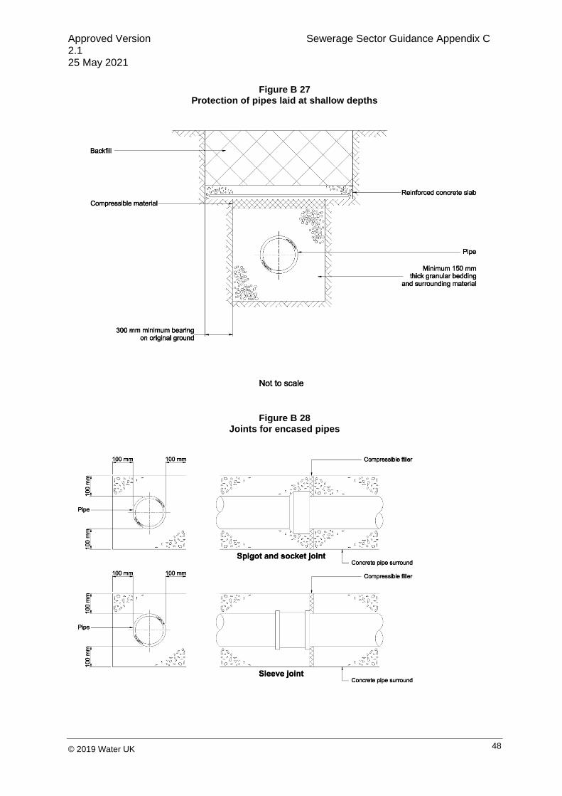
a) a concrete slab in accordance with Figure B 27; or
b) a concrete surround with flexible joints in accordance with Figure B 28; or
c) a ductile iron pipe should be used.
4. If, in accordance with B5.1.6, foul sewers and/or lateral drains are constructed under a boundary wall
not greater than 1.8 m high, a lintel should be incorporated into the wall above the pipe, in accordance
with Figure B 29, to prevent loads from the wall being transmitted to the pipe.
5. The structural design of all pipes should take into account the possible incidence of punching shear.
The design should ensure that no vertical load is imposed by structures such as shafts onto non-load
bearing components such as the pipes.
6. Where there is a risk of tree root intrusion (see B5.1.10) the sewer system should be resistant to tree
root ingress (e.g., by use of appropriate barriers or constructed from polyethylene (see E2.23) with
welded joints).
Approved Version Sewerage Sector Guidance Appendix C 2.1 25 May 2021
48 © 2019 Water UK
Figure B 27 Protection of pipes laid at shallow depths
Figure B 28 Joints for encased pipes

Approved Version Sewerage Sector Guidance Appendix C 2.1 25 May 2021
49 © 2019 Water UK
Figure B 29 Protection of pipes penetrating single leaf boundary walls
B8 MATERIALS
1. Materials should comply with the requirements of Part E.
2. Materials and components should comply with the following:
a) the manufacturing process should minimise the use of solvent-based substances that emit
volatile organic compounds or ozone-depleting substances;
b) products should be made from recycled material, where reasonably practicable; and
c) the use and/or creation of substances included in the UK Red List (DoE, 1988) of toxic
substances should be avoided during the manufacturing process.
B9 CONSTRUCTION
1. Construction of the drainage system should comply with the requirements of Part E.
2. The works should be protected, where necessary, from loads imposed by construction plant during
construction.
B10 TESTING
1. Testing of the drainage system should comply with the requirements of Part E.

Approved Version Sewerage Sector Guidance Appendix C 2.1 25 May 2021
50 © 2019 Water UK
B11 PUMPING STATIONS
1. For guidance on the design and construction of pumping stations see Part D.

Approved Version Sewerage Sector Guidance Appendix C 2.1 25 May 2021
51 © 2019 Water UK
PART C – DESIGN AND CONSTRUCTION OF NEW SURFACE WATER DRAINAGE SYSTEMS
Appendix C
Approved Version Sewerage Sector Guidance Appendix C 2.1 25 May 2021
52 © 2019 Water UK
C1 INTRODUCTION
1. The purpose of surface water drainage is to carry water away from buildings and yards belonging to
buildings in a manner that manages flood risk and water quality. Some types of surface water drainage
can also enhance amenity and biodiversity. Local authorities can also require surface water drainage
systems to meet requirements for flood risk, water quality, amenity and biodiversity.
2. Local authorities have key functions in determining the surface water drainage arrangements as
follows:
a) as the local planning authority (LPA). The LPA approves the surface water drainage
arrangements for new developments and redevelopments in accordance with the National
Planning Policy Framework (NPPF), local policies and any supplementary planning
documents;
b) as the lead local flood authority (LLFA). The LLFA provides guidance to the LPA as statutory
consultee in all major developments. They may provide advice for other developments;
c) as the local land drainage authority (LDA). The LDA regulates any work carried out in or in
proximity to non-main rivers (ordinary watercourses) except in areas where there is an
internal drainage board (see C1.5).
In Part C where the term 'local authority' is used in this guidance, it can mean any or all of these roles.
3. In areas where there are both district and county councils, the district council is the LPA and the
county council is both the LLFA and the LDA. Note: Some authorities have delegated their LLFA
functions to others.
4. The Environment Agency provides guidance to the LPA in areas that are designated critical
drainage areas and sites within 20 m of a main river as a statutory consultee. It also regulates any work
carried out in or in proximity to any main river.
5. In some areas there are internal drainage boards which regulate any work carried out in or in
proximity to non-main rivers (ordinary watercourses). Where they do not exist, these powers are carried
out by the local land drainage authority (see C1.2 c)).
6. The NPPF gives an expectation that sustainable drainage systems (SuDS) should be used as first
preference in developments of any size. The Ministry of Housing, Communities and Local Government
(MHCLG) has also issued practice guidance to support the NPPF in a number of areas.
7. The Department for Environment, Food and Rural Affairs (Defra) have also issued ‘Non-statutory
Technical Standards for Sustainable Drainage Systems’ in England. The Association of SuDS
Authorities (formerly called LASOO) has also issued practice guidance in relation to both the NPPF and
the non-statutory technical standards.
8. The designer should submit detailed construction drawings and calculations to show how the
proposed design meets the requirements of the local authority, with confirmation of the arrangements
for the operation and maintenance of the system in perpetuity.

Approved Version Sewerage Sector Guidance Appendix C 2.1 25 May 2021
53 © 2019 Water UK
9. For those parts of England where the sewerage company is one whose area is mainly in Wales2,
other Regulations apply3.
C2 SCOPE
1. Part C gives guidance for the design and construction of new surface water drainage systems that
are intended for adoption by sewerage companies, in accordance with an agreement under Section
104 of the Water Industry Act 1991.
C3 GENERAL
1. To be capable of adoption by the sewerage company, a component must come within the meaning
of a ”sewer” (see A6.19) or ”lateral drain” (see A6.11) in accordance with the Water Industry Act 1991.
Subject to careful assessment of the particular features of the component in each case, the features
listed in C7.2 to C7.13 are potentially adoptable as public sewers or lateral drains.
2. This guidance provides the mechanism by which sewerage companies can secure the adoption of a
wide range of SuDS components that are compliant with the legal definition of a sewer4. This is a
significant step change which will deliver better managed and integrated surface water systems, that
align more closely with the direction of government and regulatory policy.
3. Providing a route for adoption allows the four pillars of SuDS design to be properly considered and
utilised, with the production of resilient surface water systems that integrate all four. This will enable
new development to be more sustainable and deliver a wider range of multi-functional benefits.
4. A component is potentially adoptable as a sewer (or lateral drain) if all of the following apply (please
note that this is a non-exhaustive list and not all structures that meet the following criteria will be
adoptable):
a) it is constructed for the drainage of buildings and yards appurtenant to buildings;
b) it has a channel (a depression between banks or ridges with a definite boundary);
c) it conveys and returns flows to a sewer or to a surface water body or to groundwater; and
d) it has an effective point of discharge, which must have lawful authority to discharge into a
watercourse or other water body or onto or into land. As with conventional piped systems, this
right to discharge must be secured by the developer and transferred to the sewerage
company on adoption.
2 Currently Dŵr Cymru Welsh Water is currently the only company wholly or mainly in Wales with any part of its
operating area in England. 3 This is likely to change when the relevant provisions of the Wales Act 2017 are commenced.
4 Water UK has published a brochure "Sewers for Adoption in England – a changed approach to surface water
sewers".

Approved Version Sewerage Sector Guidance Appendix C 2.1 25 May 2021
54 © 2019 Water UK
5. The following components are not adoptable as sewers:
a) watercourses as defined in law (these include rivers, streams and can include some
ditches)5;
b) components built primarily for the drainage of surface water from streets or for the drainage of
land;
c) components built to manage groundwater;
d) components which are part of the structure of a building or yard (e.g., green roof, pervious
driveway or guttering and rainwater pipes attached to the building); and
e) components which are an integral part of the structure of a street (e.g., a pervious street or
the channel formed by the kerb of a conventional road or a channel formed by a depression in
the centre of a street).
6. Where surface water sewers are to be adopted by the sewerage company, then this may include all
surface water sewers and lateral drains (this is different in the area of sewerage companies wholly or
mainly in Wales) being connected to the surface water sewer, except any that will be adopted by the
highway authority or other bodies. The management of other components can be covered by a
separate agreement.
7. Some SuDS are not adoptable by sewerage companies because they are not correctly described as
sewers or drains when the physical component is assessed as a whole. These include pervious
pavements, green roofs and filter strips. These components may form part of the drainage design as
part of a holistic design provided they are upstream of the adoptable components or form an
exceedance flood route.
8. The developer should ensure that any components not adopted by the sewerage company are
constructed as designed. They should also make arrangements to ensure their future operation and
maintenance in perpetuity. These can include adoption by another body. The developer should provide
details of these arrangements in their S104 Application.
9. Where the operation and maintenance of a component managed by another body could adversely
impact on the sewerage company's system, an agreement should be in place to protect the sewerage
company's system.
10. The designer should take account of the cost of future maintenance activities identified in the
maintenance plan (see A5.5) as well as the initial capital costs.
11. The local authority can specify requirements for the design of surface water drainage systems that
are different to those set out below. The design of the adoptable components should comply with the
guidance in this section, in addition to the requirements of the local authority. Where any local authority
5 Water UK has published a Protocol for correctly classifying Culverted Watercourses and Sewers this is
available at https://www.water.org.uk/publications/water-industry-guidance/protocol-correctly-classifying-
culverted-watercourses-and

Approved Version Sewerage Sector Guidance Appendix C 2.1 25 May 2021
55 © 2019 Water UK
requirements conflict with the guidance in Part C, this should be brought to the attention of the
sewerage company at the earliest opportunity.
12. The government guidance to local authorities includes a hierarchy of connection, which can be
summarised as follows:
a) surface water runoff is collected for use;
b) discharge into the ground via infiltration;
c) discharge to a watercourse or other surface water body;
d) discharge to a surface water sewer, highway drain or other drainage system, discharging to a
watercourse or other surface water body;
e) discharge to a combined sewer.
13. Where a developer proposes to connect surface water to the existing sewer system they should
submit evidence to show how the surface water hierarchy has been applied to the site and why the
connection to the sewer is the most practical solution. They should also show that this has been
accepted by the LPA and in the cases of major developments, they should also show that this has been
reviewed by the LLFA.
14. The location of adoptable drainage components should take account of the need to provide
appropriate access to each component for maintenance.
15. The health and safety risks associated with any open water should be assessed and managed in
accordance with Chapter 36 of CIRIA Report C753 ‘The SuDS Manual’. Where the proposed drainage
system incorporates any surface components, the design should be carried out in accordance with
Chapter 36 of ‘The SuDS Manual’ and a copy of the principal designer's risk assessment should be
submitted to the sewerage company.
16. The developer should submit completed copies of the relevant checklists from Appendix B of the
CIRIA Report C753 ‘The SuDS Manual’ with their S104 Application. In all cases this should include
CIRIA Report C753 ‘The SuDS Manual’ Tables B.3, B.4, B.5 and B.22. It should also include Tables
B.6 to B.21 for each of the components used.
C4 SEPARATE SYSTEMS
1. Separate foul and surface water systems should be provided.
2. If, subject to the approval of the local authority (see C3.11 and C3.12), surface water sewers are to
discharge into an existing combined (single pipe) sewer system, the separate foul and surface water
sewers should be combined at locations immediately upstream of the point where they discharge into
the existing combined sewer system. Where there is a risk of the combined sewer surcharging and
backing up into the proposed surface water system, a non-return valve should be fitted.
3. The sewerage company has no duty to accept runoff from streets. The developer should note that
acceptance of this runoff into the works and, ultimately, the public sewer system, is only by agreement
which will not be unreasonably withheld (see A8 for further details).

Approved Version Sewerage Sector Guidance Appendix C 2.1 25 May 2021
56 © 2019 Water UK
4. The sewerage company has no duty to accept land drainage runoff, flows from watercourses or
groundwater. The developer should note that permission to discharge these flows into the works is not
normally given (see A9 for further details).
C5 LAYOUT PRINCIPLES
1. The layout of the development is fundamental to the performance and affordability of the drainage
system as well as the wider urban design, including the character of development, amenity,
biodiversity, connectivity and the use of the site. The layout of the whole development, including the
drainage layout should, therefore, be considered at the earliest stages of the design of the
development. ‘Building for Life 12’ recommends that designers “Explore how a holistic approach to
design can be taken to the design of sustainable urban drainage by exploiting the topography and
geology”.
2. Holistic design should work with the topography, existing site features and vegetation to create a
harmonious and practical physical and visual layout that integrates various types of access and
transport modes (including walking and cycling), drainage, public open space, an attractive street scene
and biodiversity within a context of safe and practical design.
3. The location of adoptable drainage components within the system should take account of the needs
for access for maintenance.
4. Where maintenance could require the use of a tanker, the access should be suitable for a tanker with
a capacity equal to the capacity of the component, up to a maximum of 18,000 litres. The access
should include appropriate turning facilities, where necessary.
5. Where in accordance with the maintenance plan access is anticipated to be required for tankers or
other maintenance vehicles, an access road with an appropriate surface and rights of way should be
provided.
6. Surface water systems should not create a raised reservoir (see A6.17) with a capacity in excess of
10,000 m3.
7. The layout of pipe systems should be in accordance with B4 and B5.
8. Surface water pumping stations should only be used where there is no other practicable method of
surface water drainage and an adequate exceedance flood route is provided in the event of failure of
the pumping station (see C6.3). Where a developer proposes to construct a surface water pumping
station, they should have early discussions with the sewerage company.

Approved Version Sewerage Sector Guidance Appendix C 2.1 25 May 2021
57 © 2019 Water UK
C6 HYDRAULIC DESIGN
C6.1 General
1. The hydraulic design should take account of the requirements of the local authority and the guidance
below. The local authority can specify criteria, including design rainfall rates, design flood protection
frequencies and allowances, for climate change and urban creep.
2. The hydraulic design should be carried out in accordance with the CIRIA Report C753 ‘The SuDS
Manual’. The hydraulic design of pipelines and other conduits should be designed in accordance with
BS EN 16933-2.
3. Surface water sewer systems should be designed to take the runoff from roofs, yards belonging to
those buildings and, subject to the agreement of the sewerage company, the runoff from streets (see
A8) including any flows through pervious pavements where they discharge into the system. For these
areas, an impermeability of 100% should be assumed unless it can be demonstrated that the proposed
management arrangements will limit the rate of runoff to a lower level. An impermeability of 100% for
the whole site area (including soft landscaped areas) should be used in all cases when determining
exceedance flows.
4. The sewerage company is not obliged to accept runoff from land drainage (see A9) or flow from
watercourses. In these cases, the developer should agree satisfactory and separate arrangements with
the local authority and the sewerage company.
5. An appropriate flow simulation method that can simulate flooding from the drainage system should
be used for hydraulic design, unless otherwise agreed with the sewerage company. A simple
calculation method is likely to be acceptable in the case of small developments.
6. Where a component is designed to convey or store flows in excess of the 1 in 30 year return period
event, the designer should demonstrate that the upstream system (including any inlets such as gullies
or pervious paving) has the capacity to allow the flows to reach the component.
7. In some cases it is not practical to design a particular component to convey all of the flows necessary
(for example, because the infiltration capacity is limited, or the inlets would not have sufficient capacity).
In these cases, the additional capacity required to meet the local authority's requirements may be
provided using another component or a designated overland flow route (see CIRIA Report C635
‘Designing for Exceedance in Urban Drainage - Good Practice’). Where an overland flow route is used,
it should not be designed to operate more frequently than in a 1 in 30 year return period design rainfall
event.
C6.2 Control of Surface Water Discharges from the Site
1. The local authority can impose restrictions on the method of discharge of surface water from a
development on the rate and volume of discharge. They can also specify the frequency and duration(s)
of the design rainfall used to calculate the discharge, including any allowance for climate change and
urban creep.

Approved Version Sewerage Sector Guidance Appendix C 2.1 25 May 2021
58 © 2019 Water UK
2. Where storage is provided to control surface water discharges from the site, the designer should
demonstrate that:
a) the upstream system (including the inlets) has sufficient capacity to deliver the design flows to
storage, either in its entirety (see C6.3.1) or in combination with overland flow pathways (see
C6.2.2 b);
b) an overland flow pathway (see C6.5) is provided that will safely manage any exceedance
flows.
3. The design of storage should take into account the frequency and extent of any surcharge in the
downstream system, including flood levels at any discharge point into a watercourse, lake or pond.
Note: The levels in watercourses and groundwater bodies can vary both seasonally and in response to
rainfall. Sewer pipes will typically surcharge (i.e., the water level in manholes will rise above the level of
the soffit of the pipe) much more frequently than the design flooding frequency.
C6.3 Drainage Components on the Surface and Infiltration Systems
1. The capacity of surface level components (e.g., swales, ponds and basins) is not normally
constrained by the capacity of the inlet system in the same way as underground components. They
may, therefore, be designed to accept higher flow rates than underground drainage systems up to the 1
in 100 year rainfall event plus climate change standard typically required by local authorities.
2. Provided there is provision for the flows to reach a particular feature, surface SuDS features
designed to take 1 in 100 year rainfall event plus climate change will normally be adoptable.
3. Components that are designed to be filled with water intermittently (e.g., basins or swales) should be
designed so that the water is apparent at least a few times a year to ensure that the public are aware of
their function. Where appropriate, signage should be provided to indicate:
a) that the area can be filled with water; and
b) to describe the flood risk management function of the component.
4. Further guidance on the hydraulic design of surface drainage components, including appropriate
hydraulic roughness values can be found in Chapters 3 and 24 of the CIRIA Report C753 ‘The SuDS
Manual’.
5. Guidance on the hydraulic design of infiltration drainage components can be found in Chapter 25 of
the CIRIA Report C753 ‘The SuDS Manual’.
6. The infiltration potential of the soil and subsoil used in the hydraulic design of infiltration components
should be confirmed by geo-technical tests, taking account of the seasonal variation in groundwater
conditions. Guidance on this can be found in Chapter 25 of the CIRIA Report C753 ‘The SuDS Manual’.
The highest groundwater level should be at least 1m below the base of the proposed infiltration
component. A completed copy of the infiltration potential checklist (CIRIA ‘The SuDS Manual’ Table
B.6) should be submitted with the S104 Application.

Approved Version Sewerage Sector Guidance Appendix C 2.1 25 May 2021
59 © 2019 Water UK
7. On sloping sites, the impact of the infiltration on neighbouring land should be taken into account.
C6.4 Underground Drainage Components
1. Underground drainage systems include piped sewers and drains, and underground attenuation
storage tanks.
2. The Colebrook-White hydraulic roughness value (ks) for surface water sewer and lateral drain pipe
design should be 0.6 mm.
3. Underground drainage pipes should be designed under pipe full conditions to accept the following
design rainfall (i.e., without surcharging above pipe soffit):
• sites with average ground slopes greater than 1% 1 year;
• sites with average ground slopes 1% or less 2 year; and
• sites where consequences of flooding are severe 5 year.
(e.g., existing basement properties adjacent to new development)
4. The capacity of pipe should be increased further where it is necessary to comply with the flooding
protection requirements.
5. The capacity of inlets to the systems (e.g., gullies or pervious paving systems) can limit the flows that
can enter underground drainage systems. Gully systems designed in accordance with the ‘Design
Manual for Roads and Bridges’ (HA 102/17) will not admit all the flows from streets into an underground
system during extreme events (e.g., 1 in 100 years). Where the design of the system requires that flows
from rainfall events in excess of the capacity of the gully systems are conveyed or stored in an
underground system, the designer should use alternative inlets systems with higher capacity.
C6.5 Exceedance Flow Management
1. During exceptionally wet weather, in excess of the design conditions specified by the local authority,
the capacity of the surface water drainage system can be inadequate and flooding can occur. Surface
water drainage system components should be located so as to minimise the risk of damage to buildings
or other critical infrastructure in the event of sewer flooding.
2. Flooding can also occur due to blockages, pumping station failure or surcharging in downstream
sewers.
3. In designing the site sewerage and layout, developers should identify the flow paths and understand
the potential effects of flooding They should then design flood exceedance routes to mitigate its impact,
where practicable. Guidance of design of flood exceedance routes can be found in CIRIA Report C635
‘Designing for Exceedance in Urban Drainage – Good Practice’.

Approved Version Sewerage Sector Guidance Appendix C 2.1 25 May 2021
60 © 2019 Water UK
C7 DETAILED DESIGN OF COMPONENTS
C7.1 General
C7.1.1 Sediment management
1. An effective means of sediment control should be provided within the drainage system and
particularly upstream of any attenuation component (e.g., pond, wetland, basin or tank), infiltration
component, filtration component or outfall.
2. The sediment control system should not only capture sediment under low flows but ensure that
sediment is not re-entrained and washed out under peak flow conditions.
3. Sediments can be controlled by various means including catch-pits, hydrodynamic vortex separators
and (in ponds, wetlands, basins and bio-retention systems) by use of a sediment forebay. An effective
means of sediment control should be provided within the drainage system upstream of any attenuation
component (e.g., pond, wetland, basin or tank), infiltration component, filtration component or outfall.
4. Sediment management components should incorporate access to and into the component for
removal of accumulated sediment. This should include provision of appropriate vehicular access to
facilitate removal. The operations and maintenance plan should describe procedures for sediment
removal.
5. Where there is any risk of sediment entering an underground tank, provision should be made for
removal of the sediment.
C7.1.2 Infiltration components
1. In almost all cases, infiltration drainage components can be constructed in proximity to buildings
without any detrimental impact on building foundations. However, in some ground conditions problems
can occur particularly, where the infiltration is concentrated in a small area.
2. Where infiltration is proposed within 5 m of foundations of any buildings or other structures, this
should be agreed with a geotechnical specialist who is the designer of the foundations of the building or
structure. Details should be submitted to the sewerage company with the S104 Application. Further
guidance can be found in Chapter 25 of the CIRIA Report C753 ‘The SuDS Manual’ and 'Using SuDS
close to buildings' on the Susdrain Website
3. The local authority can impose requirements to prevent pollution of groundwater from polluted
surface water.
C7.2 Pipe Systems
C7.2.1 Layout
1. The layout of pipes laid as surface water sewers and lateral drains should be in accordance with
B5.1.

Approved Version Sewerage Sector Guidance Appendix C 2.1 25 May 2021
61 © 2019 Water UK
2. Surface water sewers and lateral drains should not normally be constructed under any building or
any structure except that they may cross under a boundary wall not greater than 1.8 m high. However,
for terraced properties it is sometimes necessary to install intermediate rainwater pipes, along the
length of the terrace, to take rainwater from more than one property. Where it is not reasonably
practicable to route the sewer around the building, surface water sewers with a nominal internal
diameter of no more than 100 mm may be laid under a building, provided that the sewer takes the
drainage from no more than one rainwater pipe with a nominal internal diameter of no more than DN75,
or the equivalent cross-sectional area, provided that the entry point to the rainwater pipe is in the land
owned by the building concerned. Where such a solution is proposed for adoption, it should be
discussed with the sewerage company at the earliest stage.
C7.2.2 Access
1. Access should comply with the requirements of B5.2.
2. Access points, and any inlets to drains or sewers, should be located so as to minimise the risk of
damage to buildings or other critical infrastructure in the event of sewer flooding.
C7.2.3 Reliability
1. The minimum size for a gravity surface water sewer should be 150 mm nominal internal diameter,
except where a 100 mm nominal internal diameter is permitted, in accordance with C7.2.1.2.
2. The minimum size for a gravity surface water lateral drain should be 100 mm nominal internal
diameter.
3. To provide a self-cleansing regime within surface gravity sewers, the minimum flow velocity should
be 1 m per second at pipe full flow. Where this requirement cannot be met, then this criterion would be
considered to be satisfied if:
a) a 150 mm nominal internal diameter gravity sewer is laid to a gradient not flatter than 1:150;
or
b) a 100 mm nominal internal diameter lateral drain is laid to a gradient not flatter than 1:100.
4. These parameters should not to be taken as a norm when the topography permits steeper gradients.
Hydraulic studies indicate that these requirements may not necessarily achieve a self-cleansing regime.
When a choice has to be made between gravity sewerage and pumped sewerage, these criteria should
not be regarded as inflexible and the developer should consult the sewerage company.
5. Pipe systems should comply with the requirements of B6.3 to B6.8.
C7.2.4 Structural design and integrity
1. Structural design and integrity of pipe systems should comply with the requirements of B7.

Approved Version Sewerage Sector Guidance Appendix C 2.1 25 May 2021
62 © 2019 Water UK
C7.3 Swales
1. A swale is a shallow, vegetated channel designed to convey and retain water but may also permit
infiltration.
2. Where a swale is adopted it will usually include the sides and base of the channel, any vegetation
that is part of the function of the swale and any under-drainage including any liner, check dam, flow
control or erosion control measure.
3. The design of swales should be carried out in accordance with Chapter 17 of the CIRIA Report C753
‘The SuDS Manual’.
4. Swales proposed for adoption should typically be located in verges or other public open space or on
the boundary between the street and a private garden. Where they are not adjacent to a street,
provision should be made for access by maintenance equipment.
5. A completed copy of the design assessment checklist for swales (CIRIA Report C753 ‘The SuDS
Manual’ Table B.13) should be submitted with the S104 Application.
C7.4 Rills
1. A rill is a small, shallow lined channel through which surface water can flow.
2. Where a rill is adopted it will usually include the material forming the sides and base of the channel
and any check dam or flow control device.
3. Rills proposed for adoption should typically be located in verges or other public open space or on the
boundary between the street and a private garden. Where they are not adjacent to a street, provision
should be made for access by maintenance equipment. Sewerage companies will not adopt rills that
are part of the structure of a street (see C3.5 e)).
C7.5 Bioretention Systems
1. A bioretention system is a shallow planted depression that allows runoff to pond temporarily on the
surface, before filtering through vegetation and underlying soil prior to collection or infiltration. In its
simplest forms, it can be a tree pit or a rain garden. Engineered soil (gravel and sand layers) and
enhanced vegetation can be used to improve treatment performance.
2. The channel is formed by the banks of the depression. The effective point of discharge may take the
form of a properly-designed means of infiltrating the water into the ground below or an overflow to
another sewer.
3. Where a bioretention system is adopted, it will usually include the whole area used for temporary
ponding of water and the inlet and outlet structures and any engineered soil structures, including the
vegetation.

Approved Version Sewerage Sector Guidance Appendix C 2.1 25 May 2021
63 © 2019 Water UK
4. Detailed design should be carried out in accordance with Chapter 18 of CIRIA Report C753 ‘The
SuDS Manual’.
5. Bioretention systems should be designed to drain down within 24 hours.
6. A completed copy of the design assessment checklist for bioretention systems (CIRIA Report C753
‘The SuDS Manual’ Table B.15) should be submitted with the S104 Application.
C7.6 Ponds and Wetlands
1. A pond is a permanently wet depression designed to temporarily store surface water runoff above
the permanent pool.
2. A wetland is a type of pond with a high proportion of shallow zones that promote the growth of
bottom-rooted plants.
3. The channel may be considered as being formed by the depression between the banks of the pond
or wetland.
4. Where ponds are adopted, this will usually include the inlet and outlet structures (including flow
controls) and the entire area of the pond, including any banks that are designed to retain water, any
storage below the ground surface, impermeable liners and under drains.
5. The maximum water level in any pond should be at least 500 mm below the lowest floor level of any
adjacent properties.
6. The maximum design storage depth should give a freeboard of 600 mm below the top of the banks.
7. Design should be carried out in accordance with Section 23 of the CIRIA Report C753 ‘The SuDS
Manual’.
8. Where wetlands are used for flow attenuation, the depth of temporary storage above the permanent
water level should be limited so that the risk to plant damage is low.
9. A completed copy of the design assessment checklist for ponds and wetlands (CIRIA Report C753
‘The SuDS Manual’ Table B.21) should be submitted with the S104 Application.
C7.7 Basins
1. A basin is a depression in the ground that is normally dry but is designed to store surface water
before infiltration (infiltration basin) and/or to provide attenuation (detention basin).
2. The effective point of discharge can be a properly-designed means of infiltrating the water into the
ground. The channel may be considered as being formed by the depression or between the banks of
the basin.

Approved Version Sewerage Sector Guidance Appendix C 2.1 25 May 2021
64 © 2019 Water UK
3. Where basins are adopted, this should usually include the inlet and outlet structures (including flow
controls) and the entire area of the basin including any banks that are designed to retain water, any
storage below the ground surface, impermeable liners and under drains.
4. Design should be carried out in accordance with Chapter 22 of the CIRIA Report C753 ‘The SuDS
Manual’.
5. The maximum water level in any basin shall be at least 500 mm below the lowest floor level of any
adjacent properties.
6. The maximum design storage depth should give a freeboard of between 400 mm and 600 mm below
the top of the banks, depending on the scale of the component.
7. Infiltration basins should be provided with an inlet flow spreader to distribute flows across the basin,
ideally using a widening grass channel inlet. The base should be level across the basin to encourage
even infiltration with a slight fall of between 1 in 100 and 1 in 200 along the basin to distribute water
evenly.
8. A completed copy of the design assessment checklist for basins (CIRIA Report C753 ‘The SuDS
Manual’ Table B.19) should be submitted with the S104 Application.
C7.8 Tanks
1. A tank is an underground structure that creates a void space for the temporary storage of surface
water before infiltration, controlled release or use.
2. Tanks should have provision for access for inspection and cleaning. This should include a means of
removing any sediment and a means of trapping sediment to prevent it from being washed downstream
during cleaning operations.
3. The structural design of geocellular tanks should be carried out by a person competent to do so
using the guidance, in CIRIA Report C737 ‘Structural and Geotechnical Design of Modular Geocellular
Drainage Systems’ or other established engineering principles. Verified product performance data
should be used for the engineer to make their assessment (see E2.48).
4. The design of flow attenuation facilities should, wherever practicable, include the following criteria:
a) gravity tank sewers or tanks formed from oversized pipes should be designed as online
storage;
b) where parallel pipes are used for attenuation, a minimum of one pipe should act as online
storage, the remainder as offline;
c) the design of attenuation facilities should seek to prevent a build-up of silt and other debris
(e.g., by use of benching and low-flow channels).
5. Adequate ventilation should be provided to limit pressure build up in the system during filling. The
means of ventilation should be agreed with the sewerage company.

Approved Version Sewerage Sector Guidance Appendix C 2.1 25 May 2021
65 © 2019 Water UK
6. A completed copy of the design assessment checklist for attenuation storage tanks (CIRIA Report
C753 ‘The SuDS Manual’ Table B.17) should be submitted with the S104 Application.
C7.9 Infiltration Trenches and Filter Drains
1. An infiltration trench is a trench, usually filled with permeable granular material, designed to promote
infiltration of surface water to the ground.
2. A filter drain is a linear drain consisting of a trench filled with a permeable material, normally with a
perforated pipe in the base of the trench to assist drainage.
3. Design should be carried out in accordance with Chapter 13 of CIRIA Report C753 ‘The SuDS
Manual’.
4. Infiltration trenches/filter drains should be designed with a perforated pipe (or other suitably-defined
inspection channel) along the whole length and adequate access chambers to provide access for
inspection and maintenance.
5. A completed copy of the design assessment checklist for filter drains (CIRIA Report C753 ‘The SuDS
Manual’ Table B.11) should be submitted with the S104 Application.
C7.10 Soakaways
1. A soakaway is a subsurface structure for the temporary storage of water before it soaks in to the
ground. A soakaway is essentially a point feature; it does not have a channel.
2. To be considered for adoption, a soakaway must be fed by an upstream channel that is legally a
sewer or lateral drain that is also proposed for adoption.
3. Where a soakaway is adopted, this will usually include the whole structure up to the external face,
including any external rubble fill or membrane.
4. Design should be carried out in accordance with Chapter 13 of the CIRIA Report C753 ‘The SuDS
Manual’.
5. In considering the requirements for access (see C5.3), this should include provision of access for
removal and replacement of any fill material.
C7.11 Outfall Structures
1. Surface water outfalls discharging to watercourses should be fitted with non-return valves, where
necessary, to prevent backflow in the event of high water levels in the watercourse.
2. Design should be carried out in accordance with Chapter 28 of the CIRIA Report C753 ‘The SuDS
Manual’.

Approved Version Sewerage Sector Guidance Appendix C 2.1 25 May 2021
66 © 2019 Water UK
3. A hinged, lockable safety grille should be fitted to any surface water outfall pipe that is 350 mm
diameter or larger. Where necessary, the outfall should be angled to reduce the risk of bank erosion.
Typical details of outfalls to a watercourse are shown in
Figure C 1 and Figure C 2 and a typical detail of a grille is shown in Figure C 3. Aspects of the design
and configuration of an outfall structure may be regulated by Local Land Drainage Authorities or the
Environment Agency and therefore further input into the design may be required by the sewerage
company.
4. Access should be provided for cleaning and maintenance of the grille, and for inspection of the
outfall.
5. The design of the outfall can be subject to the approval of the local land drainage authority (see A7).
C7.12 Flow Control Devices
1. The design and location of flow control devices are to be agreed with the sewerage company.
2. Design should be carried out in accordance with Chapter 28 of the CIRIA Report C753 ‘The SuDS
Manual’.

Approved Version Sewerage Sector Guidance Appendix C 2.1 25 May 2021
67 © 2019 Water UK
Figure C 1 Typical detail of outfall to watercourse
Suitable for outfall pipes of less than 350 mm

Approved Version Sewerage Sector Guidance Appendix C 2.1 25 May 2021
68 © 2019 Water UK
Figure C 2 Typical detail of angled outfall to watercourse
Suitable for outfall pipes of less than 350 mm

Approved Version Sewerage Sector Guidance Appendix C 2.1 25 May 2021
69 © 2019 Water UK
Figure C 3 Typical outfall safety grille
For outfalls 350 mm diameter or greater

Approved Version Sewerage Sector Guidance Appendix C 2.1 25 May 2021
70 © 2019 Water UK
3. The design of flow control devices should, wherever practicable, include the following features:
a) flow controls may be static (such as vortex flow controls or fixed orifice plates) or variable
(such as pistons or slide valves);
b) where debris can enter the control (e.g., where the upstream system is open or where the
inlets are gullies), static controls should have a minimum opening size of 100 mm, or
equivalent;
c) where the design of the upstream system will prevent debris entering the system
(e.g., underground systems where the inlets are pervious pavement systems), static controls
should have a minimum opening size of 50 mm;
d) variable controls may have a smaller opening provided they have a self-cleansing
mechanism;
e) a bypass should be included with a surface operated penstock or valve; and
f) access should be provided to the upstream and downstream sections of a flow control device
to allow maintenance.
4. All flow control devices should be installed and operating before off-site discharge is made.
5. Flow control devices should have a free discharge (no downstream surcharge), where practicable.
Where it is not practicable to achieve a free discharge at all times, attenuation calculations showing
both the free discharge and surcharge conditions should be provided as part of the S104 Application.
C7.13 Proprietary Treatment Systems
1. Where treatment devices are installed on discharges from locations which have a high pollution
hazard level (as defined in Table 26.2 of the CIRIA Report C753, ’The SuDS Manual’) any treatment
device should be part of the private drainage system, or the street drainage system, as appropriate.
2. Where the developer proposes to include a proprietary treatment device as part of the system
proposed for adoption, they should consult the sewerage company at the earliest opportunity.
3. A completed copy of the design assessment checklist for proprietary treatment systems (CIRIA
Report C753 ‘The SuDS Manual’ Table B.7) should be submitted with the S104 Application.
C7.14 Landscaping and Vegetation
1. In addition to any requirements of the local authority, landscape design and vegetation should be in
accordance with Chapter 29 of the CIRIA Report C753, ‘The SuDS Manual’.
2. A management plan setting out the management objectives of the landscaping and vegetation, and
an initial management programme for at least the first five years, should be included in the overall
management plan submitted with the S104 Application (see C11).
C8 MATERIALS
1. Materials should comply with the requirements of Part E.
Approved Version Sewerage Sector Guidance Appendix C 2.1 25 May 2021
71 © 2019 Water UK
2. Materials and components should comply with the following:
a) the manufacturing process should minimise the use of solvent-based substances that emit
volatile organic compounds or ozone-depleting substances;
b) products should be made from recycled material, where reasonably practicable; and
c) the use and/or creation of substances included in the UK Red List (DoE, 1988) of toxic
substances should be avoided during the manufacturing process.
C9 CONSTRUCTION
1. Construction of the drainage system should comply with the requirements of Part E. SuDS
components should be constructed in accordance with CIRIA Report C768 ‘Guidance on the
Construction of SuDS’.
2. A construction method statement, prepared in accordance with Part E of CIRIA Report C768
‘Guidance on the Construction of SuDS’ should be submitted by the developer for approval.
3. The works should be protected, where necessary, from loads imposed by construction plant during
construction to avoid the over compaction of soils that could increase runoff from permeable areas and
adversely affect the infiltration qualities of sub-soil layers.
4. The developer should use the checklist in Part F of CIRIA Report C768 ‘Guidance on the
Construction of SuDS’ as part of their construction records and supply copies to the sewerage
company.
5. The developer should carry out a survey of the completed drainage system and produce as-
constructed drawings. These should be cross-checked with the design drawings and any variations not
previously agreed should be highlighted.
C10 INSPECTION AND TESTING
1. Inspection and testing of the drainage system should comply with the requirements of Part E with the
recommendations of CIRIA Report C768 ‘Guidance on the Construction of SuDS’.
C11 MAINTENANCE
1. A management plan setting out the management objectives of the scheme and an initial programme
should be submitted with the S104 Application to demonstrate that the systems can be economically
maintained and that appropriate access for maintenance has been provided. Additionally, long- and
medium-term strategies should be outlined as part of any submission.
2. Soft SuDS components will require regular, occasional or remedial maintenance so a simple
‘establishment’ maintenance plan for the first 5 years should be provided. However, planting, wetlands
and biodiverse (wild flower) grasslands in particular will require an over-arching management plan that
defines how it is expected that the vegetation will develop over time, and what it seeks to achieve (in
Approved Version Sewerage Sector Guidance Appendix C 2.1 25 May 2021
72 © 2019 Water UK
line with the 4 pillars of SuDS). This should be defined through a simple ‘vision statement’, supported
by appropriate management ‘aims and objectives’.
3. The management plan should require the quality and condition of the SuDS to be reviewed every 5
years, and a new maintenance plan devised for the forthcoming 5 year period that understands the
dynamic nature of the soft SuDS, and adjusts the maintenance regime as necessary to ensure their
long-term development and effectiveness.
4. The management plan should be in accordance with Chapter 32 of the CIRIA Report C753 ‘The
SuDS Manual’. It should detail:
a) regular maintenance activities;
b) occasional maintenance activities; and
c) remedial maintenance activities.
5. The management plan should detail the type of maintenance activities required, the frequency of
those activities, the estimated duration, plant and equipment requirements and estimated costs.
6. The management plan should show how appropriately-sized maintenance plant can be routed to
avoid over-compaction of areas that are required to allow infiltration.
Approved Version Sewerage Sector Guidance Appendix C 2.1 25 May 2021
73 © 2019 Water UK
PART D – PUMPING STATIONS
Appendix D
Approved Version Sewerage Sector Guidance Appendix C 2.1 25 May 2021
74 © 2019 Water UK
D1 INTRODUCTION
1. Part D of this guidance gives the industry recommendations for the design and construction of new
pumping stations and rising mains for adoption, in accordance with the provisions of an agreement
under Section 104 of the Water Industry Act 1991.
2. Some requirements for rising mains are similar to those of foul sewers and drains. In these cases,
references are made to Part B.
3. Supplementary guidance on Part D may be provided by each sewerage company. These addenda
contain individual company requirements which are permitted as a ‘Local Practice’ under the Sector
Guidance and are published on the individual sewerage company’s website.
D2 SCOPE
1. This guidance gives the industry recommendations for the design and construction of new pumping
stations and rising mains.
2. This guidance only covers submersible pumping stations not exceeding 30 kW per pump unit and
where the maximum depth of the wet well from ground level to the underside of the pump unit is 6 m.
The Specification seeks to provide a single, efficient and cost-effective design for the developer, whilst
ensuring that customers are reliably served by a robust system. Where the pumping station will exceed
30 kW, the sewerage company should be consulted for detailed requirements.
D3 DEFINITIONS
1. In addition to the definitions in A3, the following definitions also apply.
2. Classifications of pumping stations determined by size of incoming peak design flow rate are listed
below:
• Type 1 - Having an incoming peak design flow rate of ≤ 0.25 litres per second (typically
five dwellings or less);
• Type 2 - Having an incoming peak design flow rate of > 0.25 litres per second but less than 1
litre per second (typically six to twenty dwellings);
• Type 3 - Having an incoming peak design flow rate of ≥ 1 litre per second (typically more than
twenty dwellings) but with pumps rated no more than 30 kW; and
• Type 4 - Having at least one pump rated more than 30 kW (these are outside the scope of
'Sewers for Adoption' and guidance should be sought from the sewerage company).
D4 GENERAL
1. Foul sewage pumping stations or pumped systems should only be used where their whole-life cost is
less than conventional gravity systems over a period of 40 years.

Approved Version Sewerage Sector Guidance Appendix C 2.1 25 May 2021
75 © 2019 Water UK
2. Surface water pumping stations should only be used where there is no other practicable sustainable
method of surface water drainage and an adequate exceedance flood route is provided in the event of
failure of the pumping station (see C6.5).
3. Where the discharge from the rising main is at or close to the receiving sewage treatment works and
the pumped flow is a significant proportion of the flow to the treatment works, this can adversely affect
the performance of the treatment works. The sewerage company should be consulted to determine if
storage is required and the amount of storage that should be provided to balance the flows to prevent
adverse effect on the sewage treatment works.
D5 PROVISION OF PUMPING STATIONS
D5.1 Location
1. The minimum distance from the wet well of the pumping station to any habitable buildings should be
in accordance with Table D 1, in order to minimise the risk of odour, noise and nuisance. This
dimension may be subject to change, depending on the local circumstances and submission of
proposals.
Table D 1 Minimum Distances of Wet Wells from Habitable Buildings
Pumping Station Type Minimum Distance (m)
Type 1 5
Type 2 10
Type 3 15
2. The pumping station should not be located where it might be susceptible to flooding at a frequency of
more than 1:30 years. All electrical control equipment should be water resistant or sited above the
1:200 year flood level.
3. Pumping stations should be located so that they are accessible and visible to the sewerage company
at all times for use.
4. Where a pumping station serves just one curtilage, the pumping station should, wherever
practicable, be sited inside the curtilage of the property.
D5.2 Site Access
1. The pumping station should not be situated within a public or private highway, in locations which may
be used for car parking, in places where maintenance work may obstruct rights of way or where there is
a risk of harm from moving vehicles to operatives carrying out maintenance activities.
2. A safe and reasonable vehicular access should be provided to the pumping station at all hours for
the purposes of repair and maintenance. Access should be directly from the public highway or by the
provision of a dedicated access road. Vehicles should not be permitted to park in front of the vehicle

Approved Version Sewerage Sector Guidance Appendix C 2.1 25 May 2021
76 © 2019 Water UK
access point to the pumping station. Long reversing routes are not acceptable. Shared access with
domestic driveways is not suitable.
3. Provision should be made for access by a tanker to empty the wet well and any storage in the event
of failure.
4. The provision should allow for access by a tanker with sufficient capacity to completely empty the
wet well (including any provision for storage above the stop levels) and any resulting upstream in-sewer
storage up to a maximum of 18,000 litres (4,000 gallons).
5. The site of the pumping station and any access road should be suitably surfaced to ensure
reasonable access for vehicles and plant, and to facilitate the various maintenance operations.
6. The gradient of the site should be as level as possible to facilitate vehicle movements.
D5.3 Site Layout
1. The site should be arranged so that:
a) there is parking space to accommodate a tanker;
b) there is sufficient space between the various units on the site to enable maintenance
operations to be carried out safely;
c) there is sufficient space to carry out the chosen method of pump maintenance safely;
d) the need for personnel entry in to confined spaces is minimised;
e) the doors of the kiosk open safely; and
f) the pump delivery pipework (within the wet well) is opposite the inlet sewer.
2. It should be noted that the local planning authority can determine the requirements for fencing, site
layout, landscaping, etc., under the planning application but due regard should be given to health and
safety considerations.
3. Pumping stations should be secure in their own right without having to rely on security fencing.
Kiosks and all access covers should be locked and secure in their own right.
4. For smaller pumping stations, a fenced compound is not always necessary. The sewerage company
should be consulted to determine the need for a fenced compound. The sewerage company will take
account of public safety, the likelihood of vandalism, the depth of the wet well, the extent of pedestrian
traffic (e.g., near schools) and whether chemical dosing is required.
5. Where security fencing is considered necessary, unless the sewerage company specifies that
additional security is required, the type of fencing should be a 1.8 m high steel fence offering a level of
security or a 1.8 m high brick wall to match surroundings. Gates should provide a similar level of
security with slide bolt and padlock. If chemical dosing is provided on site, then the sewerage company
should be consulted.

Approved Version Sewerage Sector Guidance Appendix C 2.1 25 May 2021
77 © 2019 Water UK
6. For Type 1 and Type 2 pumping stations (see D3) adjacent to a minor road with adequate parking,
no on-site provision of parking should be necessary.
Note: The highway authority can require the provision of on-site parking as part of any planning
application.
7. Where access is from a traffic-sensitive street or other major road, or where parking provision is
unlikely to be available without obstructing the road, provision should be made for a tanker to access
and park on or adjacent to the site (e.g., in a lay-by). When accessed via a major road, any entrance
gates should be set back from the highway at least one vehicle length, based on the largest vehicle
likely to visit the site. If outward opening, the gates should be set back by the width of the leaf of the
gate.
8. On-site tanker parking should be hardstanding and surrounded by a 125 mm kerb upstand. Where
HGV access is required, the hardstanding should be 200 mm thick reinforced concrete on 500 mm type
1 granular sub-base. For smaller vehicles, permeable hardstanding should be provided.
9. There should be provision of an area of impermeable hardstanding around the wet well opening to
provide a safe working area. Where the depth of the wet well is less than 1.5 m, the hardstanding
should be 750 mm wide on all sides of the opening. Where the depth of the wet well is greater than
1.5 m, the hardstanding should be 1500 mm wide on all sides of the opening.
10. For other access covers (excluding the wet well) there should be provision of at least 750 mm width
of permeable hardstanding on all sides of the wet well. At least 750 mm wide permeable hardstanding
should also be provided in front of the kiosk.
11. For pumping stations in a fenced compound, the whole area should be covered with hardstanding.
12. For smaller pumping stations not in a compound, unpaved areas should be landscaped to match
the surface of the area around the pumping station.
13. The top of the wet well and the valve chamber should be flush with the ground level. Where there is
foul and surface water on the same site, the tops of the foul wet well and valve chamber should be
lower than the tops of the surface water wet well and valve chamber.
14. The last access point on the gravity sewer system upstream of the wet well should be within the site
compound adjacent to the wet well, and be designed to allow for overpumping. This access chamber
should also have provision for isolating the incoming flow to the pumping station by means of a hand-
operated valve or penstock.
15. A davit socket should be provided adjacent to the wet well to allow for removal of the pump units.
The davit socket should have a minimum nominal bore of 63 mm and be in accordance with Figure D1.
The location of the davit socket should allow unhindered use of the davit. The horizontal distance
between the centre of the davit socket and the centre of the lifting point on the pump unit should be no
less than 800 mm and no greater than 1200 mm. For further information on davit sockets see D7.9.

Approved Version Sewerage Sector Guidance Appendix C 2.1 25 May 2021
78 © 2019 Water UK
16. Typical layouts are shown in Figure D 2 and Figure D 3.
Figure D 1 Standard flush mount davit socket

Approved Version Sewerage Sector Guidance Appendix C 2.1 25 May 2021
79 © 2019 Water UK
Figure D 2 Typical Type 2 pumping station layout

Approved Version Sewerage Sector Guidance Appendix C 2.1 25 May 2021
80 © 2019 Water UK
Figure D 3 Typical Type 3 pumping station layout

Approved Version Sewerage Sector Guidance Appendix C 2.1 25 May 2021
81 © 2019 Water UK
D5.4 Kiosk Positioning
1. The kiosk should be positioned so that:
a) there is a minimum of 3 m between the kiosk and any vent from the wet well;
b) there is a minimum of 1 m of hardstanding in front of the wet well;
c) operators can have an unobstructed view of the top of the wet well whilst attending the
electrical assembly;
d) the doors of the kiosk do not open onto any access cover/manhole or cause an obstruction;
e) no danger will arise to operators through working on, or operating the equipment within, the
kiosk whilst the access covers of the wet well, valve chamber, etc., are open;
f) in Type 3 pumping stations, there is sufficient space to offload and position a mobile
generator adjacent to the kiosk;
g) the base of the kiosk is above flood level, see D5.1.2; and
h) the kiosk is outside any hazardous areas.
2. Where there is no separate enclosed compound, the kiosk doors should open towards the footway.
The kiosk should be at least 1 m from the footway or, where there is no footway, at least 2.5 m from the
carriageway. Where there is no footway, the kiosk doors should not open towards a carriageway.
D5.5 Storage
1. To ensure that sewage flooding does not occur at, or upstream of, the pumping station during plant
or power failure, additional storage should be provided. The base of this storage should be above the
level of the high-level alarm and the top water level of this storage should be below the invert of the
lowest lateral drain connection in the upstream network.
2. The plan area of the wet well below the level of the high-level alarm float switch level should not be
increased to form any of this required storage provision. Such storage may be provided in:
a) any upstream public sewers and public lateral drains and associated manholes and inspection
chambers, up to the level of the invert of the upstream end of the lowest public lateral drain
(storage should not be provided in private drainage and calculations should be provided); and
b) specifically-designed adjacent storage structures that are designed to be self cleansing.
3. For foul pumping stations serving less than 500 dwellings, as a minimum, the storage should equate
to 160 litres per dwelling, and for commercial or industrial developments one hour of peak design flow
rate. For pumping stations serving 500 dwellings or more, the sewerage company should be consulted
to determine the storage requirements.
4. For surface water pumping stations, 125 m3 of storage should be provided per hectare of
impermeable surface draining to the pumping station (i.e., 15 minutes of rainfall at 50 mm per hour).

Approved Version Sewerage Sector Guidance Appendix C 2.1 25 May 2021
82 © 2019 Water UK
D5.6 Hydraulic Design of Pumping Stations
1. The design flow rate of the pump units in foul pumping stations serving less than 500 dwellings
should be at least the maximum of:
a) half the incoming peak design flow rate (see Clause B3.1.1); and
b) the flow rate required to achieve a minimum flow velocity in the rising main in accordance with
D6.3.1.
For pumping stations serving more than 500 dwellings, the sewerage company should be consulted to
determine the pump rate. 2. The pumping station design static head for the pump unit design flow rate
should be based on the mid-point of the duty pump stop and start levels in the wet well. Calculations
should be provided to confirm capacities of the pumping station based on the hydraulic design.
3. The pumping station should be provided with an ultrasonic level control system. Four level set points
should be set in the wet well. These should be a "snore" level, a “pump unit stop” level, a “duty pump
unit start” level and a “standby pump unit start” level. These levels should be selected to ensure that:
a) the pump units operate safely and effectively in accordance with the pump unit manufacturer’s
instructions (i.e., the pump units do not exhibit damaging cavitation, vibration or air-locking, or
create damaging surface vortices);
b) if the wet well is in a hazardous area, the pump units do not contravene any DSEAR
requirements (the pump unit manufacturer should be consulted to this end);
c) the number of pump unit starts per hour is not more than fifteen;
d) the pump unit run time is not less than 60 seconds;
e) the combined sewage retention time in the wet well and the rising main is not more than six
hours (to prevent septicity occurring);
f) the stop level is as low as possible, without compromising the effective operation of the pump
unit. This should be the level used for automatic control and should be set at a point where
the pump unit has adequate submergence (to prevent air ingestion due to vorticity) and
adequate NPSH(a) to suppress damaging cavitation;
g) the high-level backup float switch in the wet well is not routinely activated (i.e., the standby
pump unit start level should be a minimum of 100 mm below the high-level backup float switch
in the wet well); and
h) the standby pump unit start level is a minimum of 150 mm above the duty pump unit start
level.
4. For surface water pumping stations, a check should be made to ensure that the system still meets
the requirements specified by the local authority for flood protection frequencies (see C6.1.1, C6.1.5
and C6.4.4) and to ensure no flooding occurs to properties due to pump or plant failure.
D5.7 Pumping Station Design
1. The pumping station should be either:

Approved Version Sewerage Sector Guidance Appendix C 2.1 25 May 2021
83 © 2019 Water UK
a) a package pumping station in accordance with WIS 4-04-01 or WIS 4-04-02; or
b) a bespoke design in accordance with Section D6 and Part F.
D5.8 Acceptance Testing
1. Acceptance testing requirements for pumping stations are specified in F2.4.2.
D6 RISING MAINS
D6.1 Layout and Marking
1. As far as practicable, rising mains should be laid in highways or public open space where they are
reasonably accessible. Rising mains that are sewers which serve more than one property should not be
laid in enclosed private land.
2. Rising mains should be a minimum of 3 m from any building/structure.
3. Minimum depths of cover to the crown of rising mains without protection should be as follows:
a) domestic gardens and pathways without any possibility of vehicular access – 0.75 m;
b) domestic driveways, parking areas and yards with height restrictions to prevent entry by
vehicles with a gross vehicle weight in excess of 7.5 tonnes – 0.75 m;
c) domestic driveways, parking areas and narrow streets without footways (e.g., mews
developments) with limited access for vehicles with a gross vehicle weight in excess of
7.5 tonnes - 0.9 m;
d) agricultural land and public open space - 0.9 m; and
e) other highways and parking areas with unrestricted access to vehicles with a gross vehicle
weight in excess of 7.5 tonnes - 1.2 m.
4. As far as practicable, rising mains should be laid in straight lines. Where bends are used, they should
be preformed and of long radius type. Bends should be located in places where the location of the bend
can be adequately marked with a marker post (see D6.1.6).
5. Land use surveys, "walk over", corrosion, soil chemistry and resistivity surveys should be carried out
to determine the routing, material used and the degree of corrosion protection required for rising mains
in contaminated or aggressive soils, where potentially vulnerable pipe materials are being considered.
6. The route of a cross-country rising main should be marked at every field boundary and, where
practicable, at every change of direction by approved concrete marker posts. The words "PUMPED
SEWER" and the depth to the top of the pipe in metres should be indelibly marked on the marker post.
7. For rising mains, non-degradable marker tape should be laid 300 mm above the top of the pipe. For
a non-metal main, the marker tape should incorporate a trace wire brought to the surface at a marker
post every 1000 m (approximately) and connected to terminals on the marker post. At the pumping
station, the tape should enter through a sealed duct, 300 mm below the finished paved area, and

Approved Version Sewerage Sector Guidance Appendix C 2.1 25 May 2021
84 © 2019 Water UK
should be terminated with 1 m of wire coiled inside the valve chamber. At the discharge end of the
rising main, the tape should be terminated as directed by the sewerage company.
8. Where a pumping station serves just one curtilage, the outfall from the rising main to the gravity
system should, wherever practicable, be inside the curtilage of the property.
9. Where the rising main on a Type 3 pumping station serves one property curtilage and part of the
rising main is a lateral drain, a valve chamber should be provided on the boundary to allow the flow to
be shut off and diverted to a take-off point with a Bauer coupling with a diameter of 100 mm.
D6.2 Reliability
1. The minimum size for a rising main should be 80 mm nominal bore.
2. Where exceptionally it is not possible to meet all the hydraulic design criteria using a rising main of
≥ 80 mm nominal bore, the designer should consult with the sewerage company about the possibility of
using a macerator pump.
D6.3 Hydraulic Design
1. The diameter of the rising main should be such that the velocity of the discharge is in the range
0.75–1.8 m per second when the pump unit is operating.
2. The roughness value (ks) used for the design of the rising main should be shown in the calculations
submitted and should be in accordance with ‘Tables for the Hydraulic Design of Pipes, Sewers and
Channels, 6th edition - Volume II’ published by HR Wallingford:
i.e., for mean velocities up to 1.1 m per second ks = 0.3 mm; and
for mean velocities between 1.1 and 1.8 m per second ks = 0.15 mm.
3. A rising main should be laid to a minimum gradient of 1:500 rising and 1:300 falling, with sewage-
type air release valves provided at high points to facilitate air removal. However, a continuously-rising
pipeline without air valves is preferred. For rising mains longer than approximately 500 m, the following
factors should be considered:
a) retention time and septicity (it may be necessary to use chemical dosing or to reduce
retention times by using a smaller main or a smaller sump);
b) effect of hydraulic surge and cyclic loading on fatigue life of the material (copies of
calculations/reports on surge analysis should be sent to the sewerage company);
c) the effect of air accumulating at high points in the system (it may be necessary to include a
special air release valve);
d) the drawing in of air after running pump units "on snore" (it may be necessary to include a
special air release valve);
e) provision should be made for access for cleansing; and
f) washout facilities at any low points.
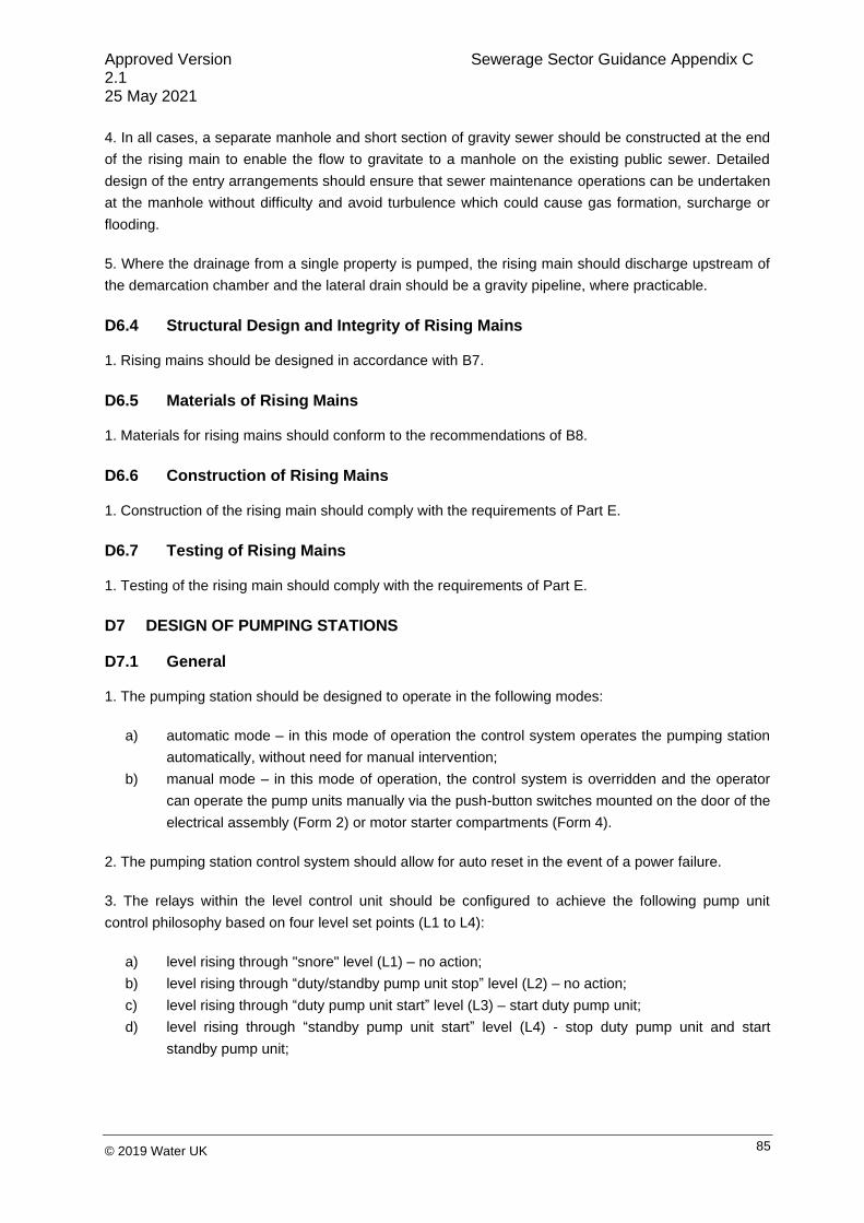
Approved Version Sewerage Sector Guidance Appendix C 2.1 25 May 2021
85 © 2019 Water UK
4. In all cases, a separate manhole and short section of gravity sewer should be constructed at the end
of the rising main to enable the flow to gravitate to a manhole on the existing public sewer. Detailed
design of the entry arrangements should ensure that sewer maintenance operations can be undertaken
at the manhole without difficulty and avoid turbulence which could cause gas formation, surcharge or
flooding.
5. Where the drainage from a single property is pumped, the rising main should discharge upstream of
the demarcation chamber and the lateral drain should be a gravity pipeline, where practicable.
D6.4 Structural Design and Integrity of Rising Mains
1. Rising mains should be designed in accordance with B7.
D6.5 Materials of Rising Mains
1. Materials for rising mains should conform to the recommendations of B8.
D6.6 Construction of Rising Mains
1. Construction of the rising main should comply with the requirements of Part E.
D6.7 Testing of Rising Mains
1. Testing of the rising main should comply with the requirements of Part E.
D7 DESIGN OF PUMPING STATIONS
D7.1 General
1. The pumping station should be designed to operate in the following modes:
a) automatic mode – in this mode of operation the control system operates the pumping station
automatically, without need for manual intervention;
b) manual mode – in this mode of operation, the control system is overridden and the operator
can operate the pump units manually via the push-button switches mounted on the door of the
electrical assembly (Form 2) or motor starter compartments (Form 4).
2. The pumping station control system should allow for auto reset in the event of a power failure.
3. The relays within the level control unit should be configured to achieve the following pump unit
control philosophy based on four level set points (L1 to L4):
a) level rising through "snore" level (L1) – no action;
b) level rising through “duty/standby pump unit stop” level (L2) – no action;
c) level rising through “duty pump unit start” level (L3) – start duty pump unit;
d) level rising through “standby pump unit start” level (L4) - stop duty pump unit and start
standby pump unit;

Approved Version Sewerage Sector Guidance Appendix C 2.1 25 May 2021
86 © 2019 Water UK
e) level falling through “standby pump unit start” level (L4) – no action;
f) level falling through “duty pump unit start” level (L3) – no action;
g) level falling through “duty/standby pump unit stop” level (L2) – stop duty pump unit if duty
pump unit running or stop standby pump unit if standby pump unit running;
h) level falling through "snore" level – inhibit both pump units (L1).
4. Plant and equipment should be reliable, efficient and capable of operating between the
manufacturer’s recommended service intervals without attention or inspection (apart from the necessity
to clear pump unit blockages, should these arise).
5. During phased developments, where the initial foul sewage flow rate is likely to be significantly below
the design flow rate when the development is complete, septicity can occur at the pumping station or at
the discharge point from the rising main. This problem should be avoided by careful design of the wet
well sump and/or by provision of chemical dosing facilities.
D7.2 Hazardous Areas
1. Parts of a sewage pumping station can be hazardous zones, in accordance with the Dangerous
Substances and Explosive Atmospheres Regulations 2002 (DSEAR). A risk assessment, taking into
account any guidance from the sewerage company, should be carried out in accordance with these
Regulations. This should be discussed with the sewerage company at an early stage.
2. Equipment installed in hazardous areas will need to take account of the Dangerous Substances and
Explosive Atmospheres Regulations 2002 (DSEAR). Appropriate measures should be taken to limit the
extent of the hazardous area, see F1.1.
3. Wet wells should be assumed to be a Zone 1 atmosphere, unless the risk assessment (taking into
account any guidance from the sewerage company) shows that protection to a less hazardous zone is
appropriate for compliance with the Dangerous Substances and Explosive Atmospheres Regulations
2002 (DSEAR).
D7.3 Wet Well - General
1. The shape of the wet well should be designed so that solid matter does not accumulate.
2. The design of the wet well and the sewer inlet arrangement should ensure satisfactory flow
conditions to the pump units and avoid the formation of damaging vortices. This is best achieved by
installing the incoming sewer on the centreline between the submersible pump units. An inlet baffle or
drop tube terminating above the start level may be provided for the sewer inlet to prevent excessive
aeration of sewage or interference with ultrasonic beams used for level sensing.
3. Benching should be provided to eliminate "dead zones" in the wet well where siltation would
otherwise occur. Benching should start no more than 100 mm from the pump unit volute. The slope of
the benching should not be flatter than 60o to the horizontal. The area under the pump should be as
small as possible to ensure effective well cleansing; flat floor areas should be kept to a minimum. The
wet well diameter should be kept to a minimum to reduce the amount of benching required.

Approved Version Sewerage Sector Guidance Appendix C 2.1 25 May 2021
87 © 2019 Water UK
4. The base of the pumping station may be made from a pre-formed concrete base (incorporating
benching), a preformed plastic base, or an in-situ formed concrete base. However, it is essential that
whatever system is employed, adequate benching is provided in the wet well to eliminate "dead zones".
5. The design of the wet well and the sewer inlet arrangement should ensure the following:
a) the formation of free surface and submerged vortices, which are damaging to the pump units,
is avoided;
b) flow is presented to the pump units in accordance with the pump manufacturer’s
recommendations and without excessive pre-swirl or air entrainment; and
c) the wet well is materially self-cleansing in terms of grit, solids and, as far as practicable,
positive buoyancy material.
6. The wet well should be designed, as far as practicable, to eliminate the need for man-entry for
maintenance. No permanent ladder or step rungs should be located in the wet well.
7. Provision for isolating the incoming flow by means of a hand-operated valve or penstock should be
located in a chamber immediately upstream of the wet well and not in the wet well itself.
8. A typical general arrangement of a wet well two pump unit station is shown in Figure D 4.
9. Pipework within the wet well should be ductile iron. Corrosion protection should comply with the
relevant requirements within the ‘Water Industry Mechanical Electrical Specification (WIMES) 4.01 –
Paints and Polymeric Coatings for Corrosion Protection’ published by ESR Technology, 2005.
D7.4 Wet Well – Structural Design
1. Clauses D7.4.2 to D7.4.5 give guidance on the structural design of reinforced concrete wet wells.
2. The minimum factor of safety against flotation for empty structures subject to groundwater pressure
is 1.1. This should only be used where the maximum groundwater level can be assessed accurately or
a design groundwater level at finished ground level is being used.
3. Precast concrete should conform to BS 5911-3 or BS EN 1917. Joints between precast components
should provide equivalent water resistance, as specified in BS EN 1992-3. The wet well should be
surrounded with not less than 150 mm thickness of Grade GEN3 concrete unless 125 mm minimum
wide wall units are used, in which case (and in accordance with manufacturers’ instructions) a concrete
surround may not be necessary.
4. If constructed of concrete, it should be designed in accordance with BS EN 1992-3. The cover slab
should either be manufactured to BS 5911 or designed to BS EN 1992-1-1 (with an applied loading
equal to accidental wheel loading) and a minimum concrete cover to reinforcement of 40 mm, provided
this meets the requirements of BS 8500-1 and BRE Special Digest 1. All concrete water-
retaining/excluding structures should be designed to satisfy cracking requirements for flexural and
thermal loading. The standard concrete mix based upon BS 8500 is C28/35 – general water-retaining

Approved Version Sewerage Sector Guidance Appendix C 2.1 25 May 2021
88 © 2019 Water UK
(and watertight) structural applications. Reinforcement should be designation H high yield steel with a
design stress of 500 N per mm2.
5. Where the wet well is constructed from flexible materials, the sewerage company should be
consulted for detailed requirements.
6. Where a rising main passes through the wall of a structure, the pipe manufacturer’s recommendation
should be followed to safeguard the integrity of the main from differential settlement/movement.
D7.5 Valve Chamber
1. The valve chamber should be separate from the wet well, but may be structurally attached to the wet
well. Valves should not be installed in the wet well.
2. For Type 1 pumping stations with a rising main length less than 5 m and where there is no risk of
surcharge of the outfall from the rising main, no valves are necessary.
3. Depending on pumping station type, the valve chamber should house the following:
a) for any type of pumping station, one gate valve per pump unit mounted horizontally in the
pump unit outlet pipework and arranged to isolate the pump units from the rising main;
b) for any type of pumping station, one check valve per pump unit mounted horizontally in the
pump unit outlet pipework upstream of the gate valves and arranged to prevent mass flow
reversal under normal operating conditions; and
c) for Type 2 and Type 3 pumping stations, a gate valve and 100 mm diameter female Bauer
coupling, mounted vertically in a tee piece in the rising main, downstream of the gate and
check valves. This should be suitable for connecting to a flexible hose to allow a mobile pump
to pump into the rising main during plant maintenance or failure.
4. The valve chamber should be provided with a hand-operated valve with a gravity drain into the wet
well. This discharge drain should be protected to ensure flows of flammable atmospheres cannot enter
the valve chamber from the wet well. The method of protection should be determined by the risk
assessment carried out in accordance with the Dangerous Substances and Explosive Atmospheres
Regulations 2002 (DSEAR).
5. Valves should comply with the Specification given in F4 and be fitted with extension spindles up to
the underside of the cover and a "T" key provided for operation, without entering the valve chamber.
6. The opening covers should extend over the full valve chamber.
7. The valve chamber should have a maximum depth of 1.5 m from cover level to floor of the valve
chamber. A typical valve chamber arrangement is shown in Figure D 4.

Approved Version Sewerage Sector Guidance Appendix C 2.1 25 May 2021
89 © 2019 Water UK
D7.6 Flow Metering
1. For Type 3 pumping stations where the pump design flow rate of any pump unit is greater than
70 litres per second, a flowmeter should be provided in the valve chamber or in a separate chamber to
monitor discharge performance.
2. Any separate flowmeter chamber should be a minimum of 1200 mm diameter, located near to the
valve chamber. It should include:
a) a flowmeter positioned in accordance with the manufacturer’s recommendations;
b) a rising main isolation valve ("T"-key operated), in accordance with F4.3; and
c) a 100 mm diameter drain to the valve chamber.
D7.7 Access into Wet Well, Valve Chambers and Flowmeter Chambers
1. Openings in access covers should be large enough to allow for pump units, valves and flow meters
to be lifted easily and safely out of the wet well/chamber for above-ground inspection, maintenance or
replacement. Openings should not be smaller than 600 mm x 600 mm.
2. Openings should have the following features:
a) covers should be lockable and fabricated from galvanized steel, finished flush with the cover
slab and provide a non-slip surface;
b) hinged covers are normally preferred. The hinged cover should incorporate a facility for
securing a recessed padlock;
c) covers and safety grids should comply with E2.32;
d) for pumping stations greater than 1.5 m deep, a hinged safety grid in two sections should be
provided;
e) for Types 1 and 2 pumping stations and Type 3 pumping stations not in a compound, the
safety grid should be provided with a 225 mm diameter slot to allow a suction hose to pass
through;
f) provision should be made within the frame to enable the main cover to be closed whilst the
pump unit and any attached cables are removed;
g) unless the lifting arrangements allow any equipment removed to be moved away from the top
of the chamber, closure of the cover should be possible with the pump unit at a minimum
height above the frame to provide a safe working platform for maintenance, in accordance
with Lifting Operations and Lifting Equipment Regulations (LOLER), 1998;
h) the cover frame should provide facilities for demountable handrailing which can be erected
prior to any maintenance on the pump units being undertaken. Depending on the site
conditions, the handrail can be fixed permanently but with removable sections to allow pump
unit removal. Chains should not be used for handrails; and
i) the handrails should withstand an impact load of 125 kg from a height of 1.85 m through a
footprint of 400 mm. Handrails should be capable of being released to allow access to the
equipment from all sides. The stanchion sockets within the frame should be flush with the
concrete slab and be sealed to prevent debris entering when not in use.

Approved Version Sewerage Sector Guidance Appendix C 2.1 25 May 2021
90 © 2019 Water UK
3. Where the wet well cannot be vented through the upstream sewer system, ventilation should be
provided in accordance with one of the following methods:
a) the installation of a stack with a minimum diameter of 75 mm and a minimum height of 4 m
with a galvanized mild steel mesh at the top;
b) if security fencing is provided, the sewerage company may allow holes/slots to be drilled in
the chequer plate before galvanizing or may permit the use of open mesh flooring made from
galvanized steel. Alternatively, an air inlet/outlet vent should be provided and positioned at
least 3 m from the kiosk/building and a minimum of 15 m from any habitable building.
The selection of the method of venting should take into account the risk of odour nuisance.
4. Vent pipes should open at the "high point(s)" of the wet well. Bends in vent pipes should be large
radius; elbow bends should not be used. Vent pipes should be installed in such a way to avoid them
becoming ineffective due to trapped water (rain, condensation, etc.) and the outlet of the vent stack
should be fitted with a grille and a mushroom shield. The external shape and colour of the vent stack
should comply with local planning requirements and conform to architectural features of similar local
installations.
5. Where the wet well is deeper than 1.2 m, stainless steel number 1.4401 to BS EN 10088-1 fixings
should be provided for a temporary ladder for man-entry into the wet well. These fixings should be
located centrally, opposite the pump unit guide rails.
6. Access to below-ground valve chambers or flowmeter chambers should be by plastic encapsulated
steel double step rungs conforming to BS EN 13101, when deeper than 600 mm.
D7.8 Cable Ducts
1. Cable ducts should be provided to route cables underground, see F3.4.4.
D7.9 Davit Sockets
1. Davit sockets should be designed and positioned to provide lifting equipment with a vertical pull on
the pump unit lifting attachments, to enable pump units to be readily raised or lowered on their guide
rail.
2. Davit sockets should be rated to lift twice the weight of each pump unit, subject to a minimum safe
working load of 500 kg. Davit sockets should be load tested in-situ and a test certificate, which is in
accordance with the sewerage company’s requirements, should be provided.
3. To prevent the ingress of water and debris into davit sockets, cover plates flush with the top of the
surrounding concrete should be provided.
D7.10 Kiosk
1. The kiosk should, as a minimum, enclose the following equipment:

Approved Version Sewerage Sector Guidance Appendix C 2.1 25 May 2021
91 © 2019 Water UK
a) the electricity distribution network operator’s supply and metering equipment. This should be
housed in a separate section of the kiosk;
b) the electrical assembly;
c) the telemetry outstation;
d) a kiosk heating and lighting system; and
e) a RCD switched 240 V socket.
D7.11 Kiosk Construction
1. The kiosk should be of a non-"walk-in" design with an open base and a one-piece roof that slopes to
its rear.
2. The walls and doors of the kiosk should be constructed from GRP encapsulated, marine quality
plywood panels with a minimum thickness of 18 mm. Panels should be joined together using stainless
steel bolts and any gaps between panels sealed with a non-biodegradable mastic sealer. The edges of
the kiosk doors and door frames should be stiffened by encapsulated steel sections.
3. Where necessary, to support the electrical assembly and all associated equipment, either:
a) the rear wall of the kiosk should be stiffened by encapsulated steel sections; or
b) a suitably-sized, 18 mm thick, varnished, marine quality, plywood backboard, meeting the
requirements of BS 1088-1, should be fitted to the rear internal wall of the kiosk.
4. Where a) above is selected in D7.11.3 above, a suitably-sized, 18 mm thick, varnished, marine
quality, plywood backboard should also be fitted to the rear internal wall of the kiosk to accommodate
the electricity distribution network operator’s incoming supply and metering equipment.
5. The walls of the kiosk should have turned bottom flanges, suitably drilled to accommodate the bolts
for securing the kiosk to a 100 mm rebate in the plinth. The bolt holes should be reinforced with 5 mm
thick, galvanized steel plates, encapsulated within the bottom flanges.
6. The quality of kiosk construction should ensure the following:
a) the thermal transmittance of the kiosk should not exceed 1.5 W per m2K;
b) the fire resistance (retention of stability, integrity and insulation) of the kiosk should be Class 2
in accordance with BS 476-7, when tested in accordance with BS 476-20 to 23 for a period of
over half an hour; and
c) the kiosk should have an IP rating of IP55 (minimum) or an equivalent.
7. Alternative forms of kiosk construction instead of GRP encapsulated marine quality plywood (e.g.,
steel) may be used in locations subject to vandalism risk (as advised by local police).
8. The doors of the kiosk should be fitted with vandal-proof, stainless steel hinges and self-latching
stays to restrain the doors in the fully-open position (minimum opening angle of 90o). One door should
have stainless steel shoot bolts at the top and bottom.
Approved Version Sewerage Sector Guidance Appendix C 2.1 25 May 2021
92 © 2019 Water UK
9. Unless planning conditions dictate otherwise, the preferred exterior colour of the kiosk should be
BS 4800 14C 39 (Dark Green).
10. The preferred interior colour of the kiosk should be BS 4800 00E 55 (White).
11. Suitably-sized weather-proof and vermin-proof ventilation grilles with fly screens, should be fitted at
low level on one side of the kiosk and at high level on the opposite side of the kiosk to ensure cross-
ventilation. Consideration should be given to the equipment being installed within the kiosk to minimise
heat or humidity generated by that equipment. Ventilation should be sufficient to restrict the
temperature in the kiosk, under all weather conditions, to a maximum of 40o C at any one time, and to
an average of 35o C over 24 hours.
12. A separate compartment should be provided within the main kiosk construction, with separate
external access from the rest of the kiosk, for the regional electricity supplier’s meter, fuses, etc., and
bulkhead light.
13. In Type 3 pumping stations, a small door or "cat-flap" should be fitted in the wall of the kiosk
opposite the electrical assembly to provide access for standby generator facilities. The "cat-flap" should
be large enough to pass the standby generator cable and connector, and be horizontally hinged at the
top. The "cat-flap" should open outwards and be lockable in the closed position from inside the kiosk
with internal shoot bolts.
14. The kiosk doors should be fitted with a multipoint locking system with hasp and staple. The hasp
and staple should be at least 90 mm long horizontally, 30 mm wide vertically and be suitable for a
30 mm padlock as a minimum.
15. Where specified by the sewerage company, the kiosk should meet the required security rating in
accordance with the Loss Prevention Certification Board Standard 1175.
16. The following notices/information plates should, as a minimum, be fitted to the kiosk:
a) a notice giving instructions for resuscitation after electric shock to be fixed to the inside of a
kiosk door;
b) in Type 3 pumping stations, a notice giving instructions for connection and use of a standby
generator, including instructions for changing back to the mains supply following restoration of
supply, to be fixed to the inside of a kiosk door;
c) an information plate giving information relating to the pump units (serial/curve numbers, FLC,
duty head and flow, etc.), the setting levels of the ultrasonic level controller and the diameter
and length of the rising main to be fixed, to the inside of a kiosk door;
d) a complete set of wiring diagrams for the electrical assembly to be fixed to the inside of a
kiosk door in a weatherproof envelope;
e) a standard, black engraved on yellow "DANGER – electrical apparatus" (with flash symbol on
a triangle) notice to be fixed to the exterior of a kiosk door. The highest voltage within the
kiosk should be indicated on this label or adjacent. In Type 3 pumping stations, the notice
Approved Version Sewerage Sector Guidance Appendix C 2.1 25 May 2021
93 © 2019 Water UK
should be manufactured from a durable plastic material and have dimensions of not less than
200 mm x 150 mm; and
f) an information plate giving the name of the site, the developer’s contact name and emergency
contact telephone number to be fixed to the exterior of a kiosk door. The notice should be
manufactured from a durable plastic material and have dimensions of not less than 200 mm x
150 mm.
D7.12 Kiosk Mounting Arrangements
1. The kiosk should be mounted 150 mm above the finished ground level on a concrete plinth. The
plinth should extend a minimum of 125 mm beyond the kiosk walls and have chamfered edges.
2. The surface of the plinth should be sufficiently level to ensure that the kiosk will seat correctly on the
plinth and that the kiosk doors will open and close without any fouling or forcing.
3. All fasteners and shims required to secure the kiosk to the plinth should be manufactured from
stainless steel. The fasteners should be stainless steel expanding bolt type, complete with large
washers to prevent damage to the GRP flange. They should be located at suitable intervals to prevent
flange distortion.
4. The bottom flange of the kiosk and plinth should be sealed with a mastic sealant to prevent water
ingress.

Approved Version Sewerage Sector Guidance Appendix C 2.1 25 May 2021
94 © 2019 Water UK
Figure D 4 Typical arrangement of a wet well submersible pumping station and valve chamber

Approved Version Sewerage Sector Guidance Appendix C 2.1 25 May 2021
95 © 2019 Water UK
PART E – CIVIL ENGINEERING SPECIFICATION
Appendix E

Approved Version Sewerage Sector Guidance Appendix C 2.1 25 May 2021
96 © 2019 Water UK
INTRODUCTION
Part E is drawn from 'CESWI' 7th edition but is not a full reproduction of the same, and is supplemented
by additional information. Any Clauses in this Part which relate to workmanship or materials not
required shall be deemed not to apply.
The Clause headings and marginal Notes for Guidance (found in italics to the left of some Clauses) are
not part of the Specification.
Where additional Clauses are required, appropriate ones may be available in the 'Civil Engineering
Specification for the Water Industry' ('CESWI' 7th edition at the time of publication).
A relevant European Standard (EN) is any European Standard covering the subject which is in force in
the European Union. In the UK, ENs are published as BS ENs. A Water Industry Specification (WIS)
may be used when there is no relevant European Standard (EN), British Standard (BS) or equivalent
available.
A European Standard, British Standard or equivalent is not normally available in the case of newly-
developed products but this is not to be seen as inhibiting the use of such products. Water Industry
Specifications deal with products such as these and are identified in Appendix IV of this guidance.
However, in the case of any newly-developed product for which no European Standard, British
Standard or Water Industry Specification (or the equivalent of either) exists, care should be taken to
ensure that the product is fit for purpose. This might be achieved by using products which have been
assessed by an independent body. The British Board of Agrément (BBA) is authorised to issue
European Technical Approvals under the provisions of the Construction Products Directive
(89/106/EEC).
Developers are advised to discuss the use of newly-developed products with the sewerage company at
the earliest opportunity.
Additional quality assurance requirements, including third party certification, may be sought by the
sewerage company as a cost-effective means of ensuring compliance with Standards. BSi Kitemarking
is an example of third party certification.
All sewerage companies have a formalised process for the approval of products that are not covered by
(as opposed to not complying with) European Standards, British Standards or Water Industry
Specifications. If the developer wishes any such product to be considered for use on his site, this
should be referred to the relevant developer services/network development/sewer adoptions manager
who will outline the necessary arrangements for its approval.

Approved Version Sewerage Sector Guidance Appendix C 2.1 25 May 2021
97 © 2019 Water UK
E1 GENERAL
(i) The Contract should prescribe the datum level for the Works, together with any master benchmarks. Precise reference of the Works to existing features or to the Ordnance Survey National Grid should be shown.
(ii) Local differences can arise between GPS and OS coordinates.
E1.1 Drawings
1. One copy of the Drawings shall be kept on the site and shall be available for use by the sewerage company.
2. All levels on the Drawings shall be related to Ordnance Survey Newlyn Datum. Details shall be provided of the level and location of the temporary benchmarks and reference points which are proposed to be used.
E1.2 Setting Out
1. The developer shall be responsible for setting out the Works and for the correctness of the position and dimensions of all parts of the Works.
E1.3 Quality of Materials, Workmanship and Tests
1. All materials and workmanship shall be subjected, from time to time, to such tests as the sewerage company may direct.
2. If required by the sewerage company, a list of the developer’s proposed suppliers and sources of materials required for the execution of the Works shall be submitted to the sewerage company. Samples shall be taken in accordance with the appropriate British Standard, where applicable.
E1.4 Examination of Work
1. The sewerage company shall be afforded the opportunity to examine any work which is about to be covered up or put out of view, and to examine foundations before permanent work is to be placed thereon.
2. At least one clear working day’s notice shall be given to the sewerage company before any formation is covered with permanent work and before testing any pipeline.
E1.5 Existing Public Sewers
1. All necessary precautions shall be taken to avoid causing any damage to, or interference with flow in, existing public sewers and shall ensure that debris, silt and mud, etc., do not enter the sewer. All necessary precautions shall be taken to avoid misconnection to existing public sewers.

Approved Version Sewerage Sector Guidance Appendix C 2.1 25 May 2021
98 © 2019 Water UK
(i) The sewerage company may also have its own health and safety provisions in respect of work carried out within or adjacent to any public sewer.
E1.6 Safety in Sewers
1. Where work is required to be carried out within or adjacent to any sewer, there shall be regard of the relevant provisions of ‘The Classification and Management of Confined Space Entries’ published by Water UK.
E1.7 British and European Standards and Other Documents
1. Any reference to a Standard published by BSi, or to the specification of another body, shall be construed equally as reference to an equivalent one. Submissions shall be in accordance with the latest published Standard which is current on the date the submission is made.
E2 MATERIALS
E2.1 Storage of Materials
1. Materials and components shall be stored in such a manner as to preserve their quality and condition to the standards required by the Specification.
(i) An understanding of manufacturer’s recommend-ations is necessary before their applicability can be assessed.
E2.2 Handling and Use of Materials
1. Materials and components shall be handled in such a manner as to avoid any damage or contamination, and in accordance with all applicable recommendations of the manufacturers.
2. Unless otherwise described in the Specification, the use, installation, application or fixing of materials and components shall be in accordance with all applicable recommendations of the manufacturers. Where appropriate, any technical advisory services offered by manufacturers shall be used.
E2.3 Water
1. Water for use with cement shall be of wholesome quality.
E2.4 Aggregates for Concrete
(i) For the limitation of total chloride ion content, see E4.2.
(ii) Marine aggregates may be used, providing the sewerage company is satisfied that the
1. Aggregates for concrete shall comply with the relevant provisions of BS EN 12620, PD 6682-1 and BS 8500-2.
2. The water absorption of aggregates for concrete designed to retain an aqueous liquid shall not exceed 3% when measured in accordance

Approved Version Sewerage Sector Guidance Appendix C 2.1 25 May 2021
99 © 2019 Water UK
total chloride content of the concrete mix complies with the Specification.
with BS EN 1097-6.
3. The proportion of coarse recycled aggregate and coarse recycled concrete aggregate shall not exceed 20% by mass of the total coarse aggregate in concrete. Fine recycled aggregate or fine recycled concrete aggregate shall not be used in concrete.
4. Recycled aggregates and recycled concrete aggregates shall only be used in contact with raw or potable water where it has been demonstrated that they are suitable for this application.
E2.5 Aggregates for High-strength Concrete Topping
1. Aggregates for high-strength concrete topping (granolithic finish) shall comply with BS EN 12620 and PD 6682-1 and be 10 mm nominal size, graded in accordance with Table E.1 in PD 6682-1 and shall have a Los Angeles Coefficient of no greater than 30.
E2.6 Sands for Mortar and Grout
(i) The requirement for sands to be washed is additional to the requirements of the Standards, but is in line with the main conclusion of CIRIA Report R59 ‘Building Sands: Availability, Usage and Compliance with Specification Requirements’.
1. Sands for mortar and grout shall comply with BS EN 13139 and PD 6682-3.
2. Sands for external rendering shall comply with the relevant provisions of BS EN 13139 and PD 6682-3.
3. All sands required to comply with BS EN 12620 and PD 6682-1, or BS EN 13139 and PD 6682-3 shall be washed sands.
E2.7 Ground Granulated Blast Furnace Slag
1. Ground granulated blast furnace slag (ggbs) for use with Portland cement shall comply with BS EN 15167-1.
2. Ground granulated blast furnace slag for use with cementitious materials shall have an alumina (Al2O3) content not exceeding 14% by mass.
E2.8 Pulverised-fuel Ash
1. Pulverised-fuel ash (pfa) for use as a component material in cementitious grout or non-structural concrete shall comply with BS EN 450-1.
E2.9 Cement
(i) The lower strength limit of 20 N per mm2 for the use of sulphate-resisting Portland cement is consistent with
1. Cement shall either:
a) be factory-produced by the cement manufacturer and comply with
the provisions of the appropriate Standard, as Table E 1; or
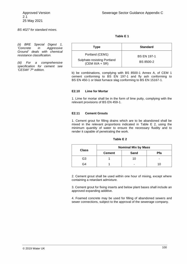
Approved Version Sewerage Sector Guidance Appendix C 2.1 25 May 2021
100 © 2019 Water UK
BS 4027 for standard mixes.
(ii) BRE Special Digest 1, ‘Concrete in Aggressive Ground’ deals with chemical resistance classification.
(iii) For a comprehensive specification for cement see ‘CESWI’ 7th edition.
Type Standard
Portland (CEM1)
Sulphate-resisting Portland (CEM III/A + SR)
BS EN 197-1
BS 8500-2
b) be combinations, complying with BS 8500-1 Annex A, of CEM 1 cement conforming to BS EN 197-1 and fly ash conforming to BS EN 450-1 or blast furnace slag conforming to BS EN 15167-1.
E2.10 Lime for Mortar
1. Lime for mortar shall be in the form of lime putty, complying with the relevant provisions of BS EN 459-1.
E2.11 Cement Grouts
1. Cement grout for filling drains which are to be abandoned shall be mixed in the relevant proportions indicated in Table E 2, using the minimum quantity of water to ensure the necessary fluidity and to render it capable of penetrating the work.
Class Nominal Mix by Mass
Cement Sand Pfa
G3 1 10 -
G4 1 - 10
2. Cement grout shall be used within one hour of mixing, except where containing a retardant admixture.
3. Cement grout for fixing inserts and below plant bases shall include an approved expanding additive.
4. Foamed concrete may be used for filling of abandoned sewers and sewer connections, subject to the approval of the sewerage company.
Table E 1
Table E 2
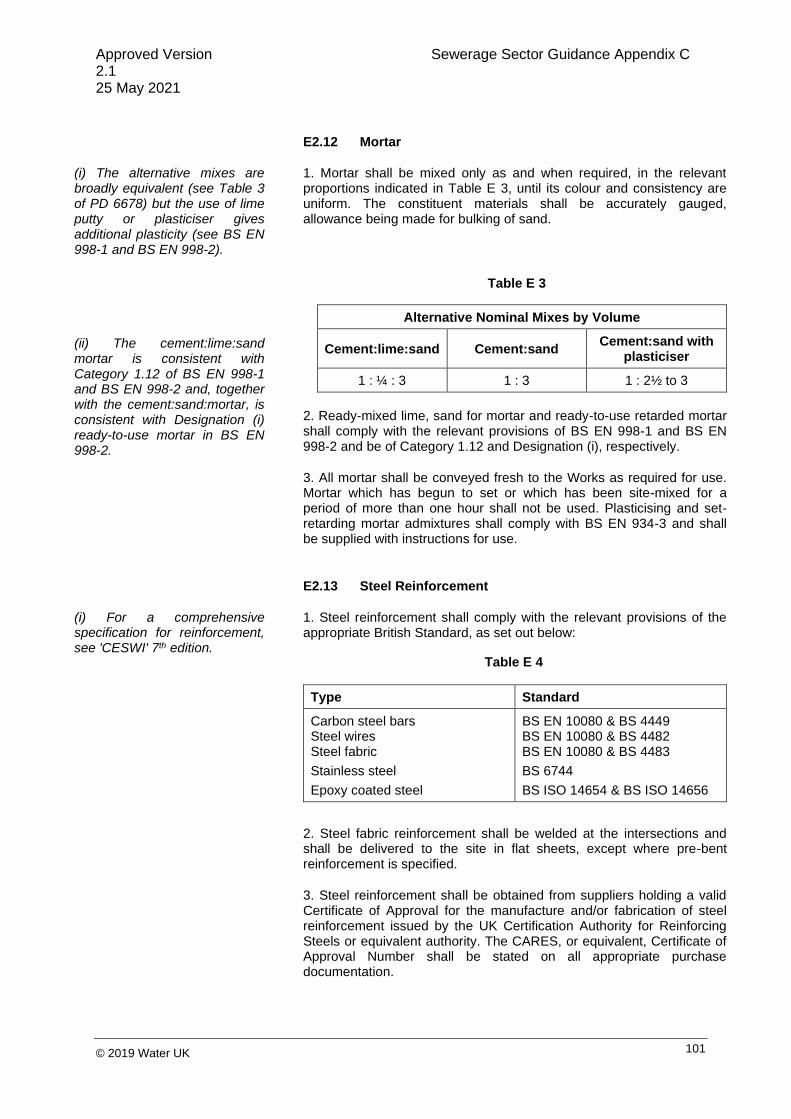
Approved Version Sewerage Sector Guidance Appendix C 2.1 25 May 2021
101 © 2019 Water UK
E2.12 Mortar
(i) The alternative mixes are broadly equivalent (see Table 3 of PD 6678) but the use of lime putty or plasticiser gives additional plasticity (see BS EN 998-1 and BS EN 998-2).
(ii) The cement:lime:sand mortar is consistent with Category 1.12 of BS EN 998-1 and BS EN 998-2 and, together with the cement:sand:mortar, is consistent with Designation (i) ready-to-use mortar in BS EN 998-2.
1. Mortar shall be mixed only as and when required, in the relevant proportions indicated in Table E 3, until its colour and consistency are uniform. The constituent materials shall be accurately gauged, allowance being made for bulking of sand.
Alternative Nominal Mixes by Volume
Cement:lime:sand Cement:sand Cement:sand with
plasticiser
1 : ¼ : 3 1 : 3 1 : 2½ to 3
2. Ready-mixed lime, sand for mortar and ready-to-use retarded mortar shall comply with the relevant provisions of BS EN 998-1 and BS EN 998-2 and be of Category 1.12 and Designation (i), respectively.
3. All mortar shall be conveyed fresh to the Works as required for use. Mortar which has begun to set or which has been site-mixed for a period of more than one hour shall not be used. Plasticising and set-retarding mortar admixtures shall comply with BS EN 934-3 and shall be supplied with instructions for use.
E2.13 Steel Reinforcement
(i) For a comprehensive specification for reinforcement, see 'CESWI' 7th edition.
1. Steel reinforcement shall comply with the relevant provisions of the appropriate British Standard, as set out below:
Type Standard
Carbon steel bars Steel wires Steel fabric
Stainless steel
Epoxy coated steel
BS EN 10080 & BS 4449 BS EN 10080 & BS 4482 BS EN 10080 & BS 4483
BS 6744
BS ISO 14654 & BS ISO 14656
2. Steel fabric reinforcement shall be welded at the intersections and shall be delivered to the site in flat sheets, except where pre-bent reinforcement is specified.
3. Steel reinforcement shall be obtained from suppliers holding a valid Certificate of Approval for the manufacture and/or fabrication of steel reinforcement issued by the UK Certification Authority for Reinforcing Steels or equivalent authority. The CARES, or equivalent, Certificate of Approval Number shall be stated on all appropriate purchase documentation.
Table E 3
Table E 4

Approved Version Sewerage Sector Guidance Appendix C 2.1 25 May 2021
102 © 2019 Water UK
E2.14 Tying Wire
1. Tying wire for steel reinforcement shall be 1.6 mm diameter annealed mild soft steel wire, complying with BS 1052.
E2.15 Cover Blocks and Spacers for Reinforcement
1. Cover blocks and spacers shall comply with BS 7973-1. To maintain the correct clear cover of concrete over steel reinforcement, they shall be as small as possible, consistent with their purpose, and of a shape acceptable to the sewerage company.
2. Concrete cover blocks shall be manufactured with a 10 mm maximum aggregate size and otherwise produced to the same specification as the surrounding concrete. Wire cast in the block for the purpose of tying it to the reinforcement shall comply with E2.14.
3. Spacers shall be of rust-proof material and shall not produce staining or otherwise be detrimental to the concrete or steel.
E2.16 Precast Concrete Products
(i) Where necessary, the surface finish should be shown on the Drawings.
1. Constituent materials of precast concrete products shall comply with the relevant requirements of this Specification, except where an appropriate European or British Standard includes specified requirements to the contrary.
2. Except where otherwise agreed or specified in a relevant European or British Standard, the surface finish of precast concrete products shall be Rough Finish for surfaces next to earth and Fair Finish elsewhere.
3. Precast concrete slabs and cover frame seating rings shall comply with the relevant provisions of BS EN 1917 and BS 5911-3.
E2.17 Plastic Sheeting and Sleeving
1. Plastic sheeting for waterproof underlay shall be free from tears and voids, and be substantially free from pinholes and other discontinuities. It shall have a composition in accordance with BS 6076 and a minimum nominal film thickness of 250 µm.
E2.18 Vitrified Clay Pipes and Fittings
(i) IGN 4-11-01 deals with vitrified clay pipes and fittings.
1. Vitrified clay pipes and fittings for sewers shall have flexible mechanical joints. Pipes for foul sewers and surface water sewers shall comply with the relevant requirements of BS EN 295-1 and BS 65 (surface water pipes only).

Approved Version Sewerage Sector Guidance Appendix C 2.1 25 May 2021
103 © 2019 Water UK
(ii) The type of joint and jointing materials for extra chemically-resistant pipes should be shown on the Drawings.
2. Extra chemically-resistant pipes and fittings shall comply with the additional requirements of BS 65.
3. Vitrified clay jacking pipes shall conform to BS EN 295-7.
E2.19 Concrete Pipes and Fittings
(i) Particular requirements from the options listed in BS EN 1916 and BS 5911 should be described.
(ii) Additional protective measures required by BRE Special Digest 1 to provide resistance to the actual ACEC (Aggressive Chemical Environment for Concrete class) should be described.
1. Unreinforced and reinforced concrete pipes and fittings shall comply with the relevant provisions of BS EN 1916 and BS 5911-1 and shall be manufactured from concrete with a Design Chemical Class DC-4 unless the sewerage company can be satisfied that a lower class will resist attack from soils and groundwater.
2. All pipes and fittings shall have gasket-type joints of spigot and socket or rebated form.
3. Unreinforced and reinforced concrete jacking pipes shall comply with the relevant provisions of BS EN 1916 and BS 5911-1. Pipes shall withstand the jacking loads to which they will be subjected during installation, without cracking or spalling. A certificate shall be supplied, confirming that the pipes are suitable for jacking and stating the distributed jacking loads for which they were designed.
E2.20 Ductile Iron Pipes and Fittings
(i) IGN 4-21-01 deals with ductile iron pipes and fittings.
(ii) IGN 4-51-01 deals with external zinc coating of ductile iron pipe, which BS EN 598 now requires on all pipes in the diameter range 80-1600 mm.
(iii) WIS 4-52-01 and IGN 4-52-02 deal with polymeric anti-corrosion (barrier) coatings. The thickness of the coatings should be such that the chemical-resistance test in BS EN 598, Section 5.6 is complied with.
1. Ductile iron pipes, fittings and joints shall comply with the relevant provisions of BS EN 598.
2. Flanges for pipes and pipeline fittings shall comply with BS EN 1092-2 for ductile iron.
3. Factory-applied coatings shall be in accordance with BS ISO 8179-1 and BS ISO 8179-2. The pipes shall be coated with a zinc-aluminium spray with an epoxy finishing layer.
4. Factory-applied and site-applied (tubular) polyethylene sleeving shall be in accordance with BS 6076.
5. Tubular polyethylene film for use as a loose protective sleeving for buried iron pipes and fittings shall comply with the relevant provisions of BS 6076, except that the nominal layflat width shall be 280 mm for use with 80 mm and 100 mm nominal internal diameter pipelines incorporating push-in flexible joints, and 400 mm for 150 mm nominal internal diameter pipelines. Sleeving for pipes for below-ground use for potable water shall be coloured blue and all other sleeving black. Joints in sleeving shall be taped so as to form a continuous barrier and any damage to the sleeving shall be repaired prior to backfilling.

Approved Version Sewerage Sector Guidance Appendix C 2.1 25 May 2021
104 © 2019 Water UK
E2.21 Thermoplastics Solid Wall Pipes and Fittings for Gravity Sewers
1. Thermoplastics pipes, joints and fittings for gravity sewers shall comply with the relevant provisions of BS EN 1401-1 (PVC-U), BS EN 1852-1 (PP), or BS EN 12666-1 (PE) as appropriate.
2. Ancillary drainage fittings shall comply with BS EN 13598-1 or BS 4660, as appropriate.
E2.22 Thermoplastics Structured Wall Pipe
1. Thermoplastics structured wall sewer pipe shall comply with the relevant provisions of BS EN 13476-1 and WIS 4-35-01 and BS EN 13476-2 or BS EN 13476-3. Pipes shall be BSi Kitemarked or have equivalent third party certification.
2. Pipes less than or equal to 500 mm in diameter shall have nominal short-term ring stiffness not less than 8 kN per m2 (SN8) or be subject to a quality system for storage and embedment.
3. Nominal short-term ring stiffness of 2 kN per m2 (SN2) is acceptable for pipes greater than 500 mm in diameter, subject to structural design load calculations in accordance with BS 9295:2019 which shall be provided to support this.
4. Maximum length of pipe for laying is 3 m or 10 x DN, whichever is the greater.
E2.23 Polyethylene Pressure Pipes and Fittings for Pressure Sewers
1. Polyethylene pressure pipes for rising mains shall comply with the relevant provisions of BS EN 12201-2. The colour shall be black.
2. Polyethylene fittings, including fittings for butt fusion and electrofusion fittings, shall comply with the relevant provisions of BS EN 12201-3.
E2.24 Joint Seals and Lubricants
1. Elastomeric joint seals shall be Type WC or WG, complying with the relevant provisions of BS EN 681-1 or TPE seals complying with BS EN 681-2, and shall be obtained from the pipe manufacturer.
2. Joint lubricants for sliding joints shall have no deleterious effect on either the joint rings or pipes, and shall be unaffected by sewage.
3. In the case of composite seals, the requirements apply only to those

Approved Version Sewerage Sector Guidance Appendix C 2.1 25 May 2021
105 © 2019 Water UK
components exposed to the contents of the pipeline or pipework.
E2.25 Pipe Surround Materials
(i) IGN 4-08-01 gives guidance on pipe surround materials.
(ii) Any limitations on the size and type of materials should be described.
(iii) The Environment Agency/ WRAP "Quality Protocol -Aggregates from Inert Waste" can be used by producers to demonstrate the suitability of aggregates.
1. Processed granular and "as-dug" bedding, sidefill and surround materials for buried pipelines shall comply with WIS 4-08-02 and BS EN 1610.
2. Processed recycled granular bed and surround materials shall comply with BS EN 13242.
E2.26 Precast Concrete Setting Blocks for Pipes
1. Precast concrete setting blocks for pipes shall have rectangular faces, with sufficient plan area to prevent punching of the blinding concrete or formation and to provide an adequate seating for the pipes. They shall be manufactured from compressive strength C16/20 concrete using the same type of cement as in the adjacent concrete bed. Blocks shall not be used until they have achieved a cube strength of 13.5 N per mm2.
E2.27 Compressible Filler and Packing for Pipelines
1. Compressible filler for interrupting concrete protection to pipes shall consist of bitumen-impregnated insulating board to BS EN 622-1 and
BS EN 622-4. The thickness of compressible filler shall be as Table E 5.
Nominal Diameter of Pipe (mm)
Thickness of Compressible Filler (mm)
Less than 450 450 – 1200
Exceeding 1200
18 36 54
2. Compressible packing for use between pipes and precast concrete setting blocks shall consist of bitumen damp proof sheeting complying with BS EN 14967.
3. Bituminous materials shall not be put into contact with plastics pipes.
Table E 5

Approved Version Sewerage Sector Guidance Appendix C 2.1 25 May 2021
106 © 2019 Water UK
E2.28 Clay Puddle
1. Clay puddle shall be impervious to water and be free from sand, grit, stones and other deleterious matter.
2. The clay, on being dug, shall be exposed to the air for at least 24 hours and, thereafter, shall be worked with water into a consistency suitable for punning. A roll of clay 300 mm long and 40 mm in diameter shall support its own weight when suspended from one end.
E2.29 Precast Concrete Manholes
(i) Particular requirements from the options listed in BS EN 1917 and BS 5911-3 should be shown on the Drawings.
(ii) Additional protective measures required by BRE Special Digest 1 to provide resistance to the actual ACEC (Aggressive Chemical Environment for Concrete class) should be described.
1. Precast concrete manhole units shall comply with the relevant provisions of BS EN 1917 and BS 5911–3 and shall be manufactured from concrete with a Design Chemical Class DC-4 unless the sewerage company can be satisfied that a lower class will resist attack from soils and groundwater. Units which bed into bases shall be manufactured so that imposed vertical loads are transmitted directly via the full wall thickness of the unit. The profiles of joints between units and the underside of slabs shall be capable of withstanding applied loadings from such slabs and spigot-ended sections shall only be used where the soffit of the slab is recessed to receive them.
2. Precast concrete chamber sections for valves and meters shall be interlocking and comply with BS EN 1917 and BS 5911-3.
3. Precast concrete corbel slabs shall comply BS 5911-3 Table 5 and Figure 8.
E2.30 Precast Concrete Manhole Components
1. Precast concrete shall comply with the relevant provisions of BS EN 1917 and BS 5911-3.
2. Corbel slabs shall comply with the requirements of BS 5911-3:2010+A1:2014 Table 5 and Figure 8.
E2.31 Thermoplastics Manholes and Inspection Chambers
1. Thermoplastics manholes and inspection chambers shall comply with BS EN 13598-1 or BS EN 13598-2.
E2.32 Manhole Covers and Frames
(i) The minimum clear opening should be as stated in B5.2.7 This will normally be: 600 mm x 600 mm
(ii) BS EN 124 is a minimum
1. Manhole covers and frames shall comply with the relevant provisions of BS EN 124, BS 7903 and ‘Design Manual for Roads and Bridges 4.2 Part 5’ HA 104/09. They shall be of a non-rocking design. Covers that transfer the load to the frame at concentrated points (e.g. at the corners of covers) shall not use cushion inserts between the cover and the frame. Aluminium covers shall not be used.

Approved Version Sewerage Sector Guidance Appendix C 2.1 25 May 2021
107 © 2019 Water UK
performance Standard only.
ii) The load test in BS EN 124 does not test frame load transfer or other factors related to durability in an appropriate way. Some D400 frames can outperform some E600 frames particularly on bedding performance.
2. Manhole covers on foul-only sewers shall be of low leakage types in order to prevent excessive surface water ingress.
3. As a minimum, Class D 400 covers shall be used in carriageways of roads (including pedestrian streets), hard shoulders, agricultural or recreational land and parking areas used by unrestricted types of road or pneumatic tyred agricultural vehicles.
4. Minimum frame depths for NRSWA road category Types 0 to 4 shall be as Table E 6. Manhole covers in shared driveways that could be subject to occasional loads from heavy vehicles (e.g., refuse vehicles) should meet the requirements for Type 4 roads.
Road Type
Traffic Capacity
Typical Description Minimum
Frame Depth (mm)
Type 0 30-125
msa Trunk roads and dual
carriageways 150
Type 1 10-30 msa
All other A roads 150
Type 2 2.5-10 msa
Bus services 150
Type 3 0.5-2.5
msa All other roads except residential cul-de-sacs
150
Type 4 up to 0.5
msa Residential cul-de-sacs
100
5. Class B 125 shall be used in footways, pedestrian areas, driveways serving a single house and comparable locations.
6. In situations where traffic loading is anticipated to be heavier than would occur on a typical residential estate distributor road (i.e., braking or turning near a junction), a higher specification (E600) shall be used. This should comprise either a Class E600 cover or a D400 of a type that has been assessed and approved by the sewerage company as having sufficient additional ruggedness to ensure durability.
7. All manhole covers shall be the non-ventilating type and shall have closed keyways.
8. All manhole covers and frames shall be provided with a prising slot to facilitate their removal.
9. Covers with a clear opening greater than 1m shall comply with BS 9124. Aluminium covers shall not be used.
10. Safety grids, where supplied, shall comply with the requirements of BS 9124. When lifted they shall be secure in the upright position. Aluminium safety grids shall not be used.
E2.33 Manhole Steps
Table E 6

Approved Version Sewerage Sector Guidance Appendix C 2.1 25 May 2021
108 © 2019 Water UK
(i) Unprotected aluminium steps should not be used.
1. Steps for manholes and other chambers shall be Type D Class 1, complying with the requirements of BS EN 13101.
2. Galvanized mild steel and plastic encapsulated steps are preferred.
E2.34 Nuts, Screws, Washers and Bolts
1. Nuts, screws, washers and bolts shall comply with the relevant provisions of the appropriate Standard, see Table E 7.
Type Standard
Metal washers for general purposes BS 4320
ISO black bolts, screws and nuts BS 4190
ISO precision bolts, screws and nuts BS 3692
High-strength friction grip bolts, nuts and washers
BS EN 14399-1
Stainless steel bolts, screws and studs (Grade 1.4401)
BS EN ISO 3506-1
Stainless steel nuts (Grade 1.4401) BS EN ISO 3506-2
2. Bolting for pipes and fittings shall comply with the relevant provisions of BS EN 1092-2 and BS EN 1515-1 except that spheroidal graphite iron bolts for use with ductile iron pipes and fittings shall be manufactured from metal complying with the provisions of BS EN 1563 and BS EN 1564 for Grade 500/7.
3. Bolt lengths and tightening torque shall be in accordance with manufacturer’s recommendations and shall be sufficient to ensure that nuts are full-threaded when tightened in their final position with two threads showing.
4. Where bolting is metallurgically incompatible with the material being fixed, the contact areas shall be isolated either by painting with an approved silicon sealant (and allowed to dry before tightening together), or with suitable isolating washers, and sleeves shall be used.
5. Washers shall be provided under the head of the bolt and under the nut.
6. Unless manufactured from stainless steel, all fasteners shall be protected against corrosion, in accordance with WIS 4-52-03.
7. Bolts, nuts and washers for flanged joints shall comply with BS EN 1092 and shall be galvanized or have other protective coating as approved by the sewerage company. Zinc plating is not acceptable as a means of corrosion protection.
Table E 7

Approved Version Sewerage Sector Guidance Appendix C 2.1 25 May 2021
109 © 2019 Water UK
E2.35 Safety Chains
(i) The location of safety chains should be shown on the Drawings.
(ii) Lifting Regulations do not apply to safety chains in sewers.
1. Safety chain shall be medium tolerance chain conforming to BS EN 818-3 Grade 4 nominal size 8 x 24.
2. After manufacture, mild steel safety chains shall be hot dip galvanized in accordance with BS EN ISO 1460 and BS EN ISO 1461.
3. Stainless steel safety chain shall be manufactured from Grade 1.4401 steel conforming to BS EN 10088-3.
4. When tested in accordance with BS EN 818-1, each chain shall withstand a breaking force of 30 kN and a proof force of 15 kN.
E2.36 Handrails and Balusters
(i) Where stainless steel tubes are to be bent to very small radii, it may be necessary to describe their condition as GKM(S) instead of KM.
(ii) BS 6180 also deals with permanent protective barriers designed to resist vehicular impacts.
(iii) BS EN ISO 14122-3 gives guidance on the construction of guardrails.
(iv) Aluminium handrails and balusters should not be used in sewers, sewer manholes, sewage pumping stations or confined spaces in sewage treatment works.
(v) Any requirements for toeboards and infill panels should be described in the Contract.
1. Protective barriers shall conform to BS 6180 with loading determined from Table NA.8 from the UK National Annex to BS EN 1991-1-1.
2. Handrails and balusters shall be manufactured from materials conforming to the appropriate British Standard, as set out in Table E 8.
Standard Grade
Mild steel – solid
Mild steel – tubular
Stainless steel – solid
Stainless steel – tubular
BS EN 10025-2
BS EN 10255
BS EN 10088-3
BS EN 10296-2
S275
HFW2
1.4401
LW17KM
3. GRP handrails and balusters shall be manufactured from pultruded sections conforming to BS EN 13706-2 and BS EN 13706-3. The surface shall be smooth with fibres embedded and sealed against penetration from dirt and water. The Barcol hardness of the sections shall be at least 35 when tested in accordance with BS EN 59.
4. After manufacture, mild steel handrails and balusters shall be hot dip galvanized in accordance with BS EN ISO 1461.
5. After manufacture, aluminium handrails and balusters shall be anodised in accordance with BS EN ISO 7599, Grade AA25.
E2.37 Ladders
(i) BS EN ISO 14122-4 gives guidance on the construction of ladders.
1. Ladders in manholes and similar structures shall comply with the requirements of BS EN 14396, with width of rung 380 mm and two stringers, but shall not be made from aluminium.
Table E 8

Approved Version Sewerage Sector Guidance Appendix C 2.1 25 May 2021
110 © 2019 Water UK
2. Mild steel ladders for vertical fixing shall be fabricated from steel conforming to BS EN 10025-2. After fabrication, low carbon steel ladders shall be hot dip galvanized in accordance with BS EN ISO 1461.
3. Stainless steel ladders for vertical fixing shall be fabricated from Grade 1.4401 steel conforming to BS EN 10088-3.
4. GRP ladders shall be manufactured from pultruded sections conforming to BS EN 13706-2 and BS EN 13706-3. The surface shall be smooth with fibres embedded and sealed against penetration from dirt and water. The Barcol hardness of the sections shall be at least 35 when tested in accordance with BS EN 59.
E2.38 Fixings for Metalwork
(i) Sizes and types of fixings should be shown on the Drawings together with minimum requirements for edge distances, centres of fixings and embedments.
(ii) For guidance on the selection and use of fixings in concrete and masonry, see CIRIA Technical Note TN137.
(iii) BS 6180 gives recommendations for fixing protective barriers.
(iv) The safe working load should be shown on the Drawings.
(v) BS 5080-1 does not give recommendations on the interpretation of the results of tests for the purposes of design, selection or use of fixings. CIRIA Technical Note TN75 deals with loading tests on fixings in concrete.
1. Mild steel bolts and nuts shall be hot dip galvanized in accordance with BS EN ISO 1461. Mild and high-tensile steel proprietary fixings shall be protected in accordance with the relevant provisions of the appropriate British Standard, see Table E 9.
Type of
Protection
Type of Fixing
Cast-in Having no Machined
Thread
Cast-in/expanding, Basic Major Diameter Machined
Thread
Not Exceeding
19 mm
Exceeding 19 mm
Hot dip galvanized
BS EN ISO 1461
- -
Electroplated zinc
BS EN ISO 2081 Zn 10
BS 7371-12 BS EN ISO
2081 Zn 10
2. Stainless steel proprietary fixings, bolts and nuts shall be manufactured from Grade 1.4401 steel complying with BS EN 10088.
3. Anchor bolts for fixing safety chains shall be of the stainless steel safety type which shall provide a progressive mode of failure.
4. Axial and shear loading tests on structural fixings in concrete or masonry shall be carried out in accordance with the provisions of BS 5080-1 and BS 5080-2, respectively.
5. Where fixings are metallurgically incompatible with the material being fixed, suitable isolating washers and sleeves shall be used.
Table E 9

Approved Version Sewerage Sector Guidance Appendix C 2.1 25 May 2021
111 © 2019 Water UK
E2.39 Bricks and Blocks
(i) The term "blocks" has been used for precast concrete masonry units.
(ii) Bricks used in bedding to manhole covers should be bonded using high-strength mortar (such as polyester resin).
1. Concrete bricks or blocks to be used in manholes and chambers shall be precast concrete masonry units, manufactured in accordance with BS 6073-2 (partially replaced by BS EN 772-2, containing a minimum of 350 kg per m3 of sulphate-resisting cement and having a maximum water:cement ratio of 0.45, a minimum compressive strength of 40 N per mm2, and a maximum water absorption of 7%.
2. Clay bricks to be used in manholes and chambers shall be solid, Class B engineering bricks complying with the relevant provisions of BS EN 771-1.
3. The shapes and dimensions of special bricks shall comply with the relevant provisions of BS 4729.
4. All bricks shall have freeze/thaw designation F2.
5. All bricks shall have active soluble salts content designation S2.
E2.40 Flexible Couplings
1. Flexible couplings for gravity sewerage and drainage pipes shall comply with the provisions of BS EN 16397.
E2.41 Joint Sealing Compounds and Sealants
(i) Fuel-resistant types of sealants to BS EN 14188-1 or BS 5212-1 may be required where concrete surfaces are subject to fuel spillage.
(ii) BS 6213 gives guidance on the selection of constructional sealants.
(iii) CIRIA Technical Notes TN128 and TN144 deal with sealants in wet conditions.
1. Joint sealing compounds shall be impermeable ductile materials of a type suitable for the conditions of exposure in which they are to be placed, and capable of providing a durable, flexible and watertight seal by adhesion to the concrete throughout the range of joint movement.
2. Hot poured joint sealants shall comply with BS EN 14188-1, Type N1 sealant.
3. Cold poured polymer-based joint sealants shall comply with BS EN 14188-2, Normal Type N sealant.
4. Primers for use with joint sealants shall be compatible with, and obtained from the same manufacturer as, the adjacent sealant. Primers shall have no harmful effects on the surfaces to which the joint sealant is to be applied.
5. Sealants and primers which will be in contact with sewage shall be resistant to biodegradation.
6. Two-part, polyurethane joint sealants shall comply with the requirements of BS EN ISO 11600.

Approved Version Sewerage Sector Guidance Appendix C 2.1 25 May 2021
112 © 2019 Water UK
E2.42 Access Covers for Pumping Stations
(i) Openings should conform to the sewerage company’s requirements and be large enough to allow pump units and other equipment to be lifted safely.
1. Covers shall be lockable, galvanized and fabricated from mild steel or ductile iron.
E2.43 Granular Sub-base Material
(i) The use of recycled material should be encouraged and should be described in the Contract.
1. Granular sub-base material shall be natural sands, gravels, crushed rock, crushed slag, crushed concrete or well burnt non-plastic shale. The material shall be well graded and lie within the following grading limits:
(ii) Recycled material for use in sub-bases is defined in the Highway Agency’s ‘Specification for Highway Works’, Series 800 Clause 807 “Type 4 (Asphalt Arisings) Unbound Mixture”.
(iii) IGN 4-08-01 gives guidance on pipe bedding materials.
BS ISO 3310-1 and BS ISO 3310-2
Test Sieve
Percentage by Mass Passing
Type 1 Type 2
75 mm 100 100
37.5 mm 85 - 100 85 - 100
20 mm 60 - 100 60 - 100
10 mm 40 - 70 45 - 100
5 mm 25 - 45 25 - 85
600 m 8 - 22 8 - 45
75 m 0 - 10 0 - 10
2. Where granular sub-base material is to be used within 450 mm of the surface of any road, the material shall have a heave not greater than 15 mm when tested in accordance with BS 812-124.
3. Natural sands and gravels shall be permitted in Type 2 material. Natural sands up to 12% only shall be permitted in Type 1 material.
4. The particle size shall be determined by the washing and sieving method of BS EN 933-1. The material passing a 425 µm BS sieve, when tested in accordance with BS 1377-2, shall be non-plastic for Type 1 and have a Plasticity Index of less than 6 for Type 2.
5. With the exception of well burnt non-plastic shale, the material shall have a “ten per cent fines” value of 50 kN or more when tested in accordance with BS 812-111.
Table E 10

Approved Version Sewerage Sector Guidance Appendix C 2.1 25 May 2021
113 © 2019 Water UK
6. Type 1 material shall be delivered to site with a moisture content within + 1% and – 2% of optimum as determined in accordance with BS 5835-1, and shall be protected, so as to be maintained within this range, until its incorporation into the Works.
7. Recycled materials shall comply with all relevant Standards and 2.55.
8. Type 4 granular material shall be a crushed waste concrete product. The material shall lie within the grading envelope of Table 8 of the ‘Specification for Highway Works’, and not be gap graded.
E2.44 Geotextiles
1. Geotextiles for use in drainage systems shall comply with BS EN 13252 and the characteristics specified in the design. A declaration of performance for each product used shall be provided for approval prior to installation.
2. Geotextiles for use in erosion control shall comply with BS EN 13253 and the characteristics specified in the design. A declaration of performance for each product used shall be provided for approval prior to installation.
3. Geotextiles shall:
a) in both machine and cross-machine directions, sustain a tensile load of not less than 8.0 kN/m at break and have a minimum failure strain of 40% when determined in accordance with BS EN ISO 10319;
b) have a minimum puncture resistance of 1500 N when determined in accordance with BS EN ISO 12236;
c) have a size distribution of pore openings such that it shall have a minimum apparent opening size O90 when determined in accordance with BS EN ISO 12956 of 75µm; and
d) allow water to flow through it, in either direction, normal to its principal plane at a rate of not less than that stated in the design under a constant head of water of 100 mm and a maximum breakthrough head of 50 mm when determined in accordance with BS EN ISO 11058.
E2.45 Geosynthetics
1. Geosynthetic barriers for lining ponds and wetlands shall comply with BS EN 13361 and the characteristics specified in the design. A declaration of performance for each product used shall be provided for approval prior to installation.

Approved Version Sewerage Sector Guidance Appendix C 2.1 25 May 2021
114 © 2019 Water UK
2. Geosynthetic barriers for lining swales and other channels shall comply with BS EN 13362 and the characteristics specified in the design. A declaration of performance for each product used shall be provided for approval prior to installation.
3. Geosynthetic barriers shall:
a) sustain a tensile load of not less than 25.0 kN/m at break and have a minimum failure strain of 800% when determined in accordance with ASTM D-638;
b) have a minimum puncture resistance of 275 N when determined in accordance with ASTM D-4833;
c) have a minimum tear resistance of 100 N when determined in accordance with ASTM D-1004.
E2.46 Imported Topsoil
(i) For the definition of in-situ topsoil see 3.3.
(ii) Any requirements for testing for club root and eelworm should be described in the Contract.
(iii) Attention is drawn to Section 14.2 of the Wildlife and Countryside Act 1981, which prohibits deposition of any plant material from any non-native invasive species listed in Part 2 of Schedule 9 of the Act (e.g., Giant Hogweed or Japanese Knotweed).
(iv) Organic land is defined as land cultivated without the addition of artificial fertiliser or use of pesticides or herbicides for at least the previous five years, as certified by the Soil Association, or other equivalent body.
1. Imported topsoil shall comply with BS 3882 and be of light or medium texture, having a pH value of between 6.0 and 7.5. Imported topsoil shall not contain stones greater than 20 mm in size nor have a total stone content exceeding 10% by mass.
2. Organic topsoil shall be imported from an organic land estate having a soil composition from a similar soil series. Details of the source and composition of the topsoil shall be provided, unless stated in the design.

Approved Version Sewerage Sector Guidance Appendix C 2.1 25 May 2021
115 © 2019 Water UK
E2.47 Engineered Topsoil
1. The chemical composition of engineered topsoil shall comply with the requirements of BS 3882.
2. The hydraulic conductivity, measured in-situ using the single ring infiltration test in accordance with BS EN ISO 22282-5 shall be as specified in the design.
3. The grading of the soil shall be as specified in the design.
E2.48 Thermoplastics modular geocellular drainage systems
1. Thermoplastic boxes, including integral components, to be used as elements in a modular geo-cellular drainage system shall comply with the requirements of BS EN 17152-1. Product performance data used in the structural design of these attenuation and infiltration systems shall be determined through testing carried out in accordance with BS EN 17150 and BS EN 17151.
E3 EXCAVATION AND BACKFILLING
E3.1 Excavation
1. Operations shall be carried out in such a manner as to prevent damage to, or deterioration of, the formation of excavations.
2. Excavation in roads and streets shall be carried out in accordance with the relevant highway reinstatement specification.
3. Excavations in locations where services may be encountered shall be carried out in accordance with ‘HSG 47 Avoiding Danger from Underground Services’.
4. Trenches shall be excavated so that the effective width is maintained within any maximum limit imposed by the design of the pipeline and the minimum limit specified in BS EN 1610. The sides of excavations shall be adequately supported at all times and, except where permitted, shall not be battered.
5. Trenches in rock for rising mains up to 100 mm nominal diameter shall be excavated to provide a minimum clearance of 100 mm around the outside of pipe barrels and joints. For pipes with nominal diameters exceeding 100 mm, the minimum clearance shall be increased to 150 mm for flexible and 200 mm for rigid pipelines.
6. If ground in the formations is encountered which is considered unsuitable, or if the formation is damaged or allowed to deteriorate, the sewerage company shall be promptly informed.

Approved Version Sewerage Sector Guidance Appendix C 2.1 25 May 2021
116 © 2019 Water UK
7. Soft spots shall be removed from the bottom of trenches and other excavations, which shall then be refilled to formation level with the same material as the permanent work which is to rest on that formation. Any void which results from over-excavation below formation level shall be refilled in the same manner.
8. Excavated granular material which can be reused shall be kept separate from excavated cohesive materials.
E3.2 Dealing with Water
(i) An Environmental Permit may be required from the Environment Agency or Natural Resources Wales.
(ii) Guidance for Pollution Prevention GPP 5 and Pollution Prevention Guidance 6 should be applied.
1. Water shall not be allowed to accumulate in any part of the Works. Water arising from, or draining into, the Works shall be drained or pumped to a consented disposal point. Any drainage sumps required shall, where practicable, be sited outside the area excavated for the permanent Works, and shall be refilled with either Type 1 granular sub-base material complying with E2.43 or lean concrete Grade GEN1 (C10) to the level of the underside of the adjacent permanent Works.
2. All necessary precautions shall be taken to prevent any adjacent ground from being adversely affected by loss of fines through any dewatering process.
3. Discharges to sewers shall not take place without the consent of the sewerage company.
E3.3 Temporary Drains
1. Where temporary drains (trench sub-drains) are required, they shall be laid in a narrow trench or grip formed below the bottom of the excavation in an approved position. The pipes shall be open-jointed and shall be surrounded with free-draining granular material (see E2.25).
2. When no longer required, temporary drains shall be removed or sealed.
3. When sealing temporary drains, grouting pipes shall be inserted in the line of the temporary drains at intervals not exceeding 25 m and the drains shall be solidly filled with grout (Class G3 or G4), the grout pipes being cut off on completion, care being taken to avoid impregnation of any granular bedding material around the main pipeline.
E3.4 Backfilling
(i) The highway authority may impose requirements for backfilling under existing highways.
1. Backfilling shall, wherever practicable, be undertaken immediately when the specified operations preceding it have been completed. Backfilling shall not, however, be commenced until the works to be covered have achieved a strength sufficient to withstand all loading imposed thereon.

Approved Version Sewerage Sector Guidance Appendix C 2.1 25 May 2021
117 © 2019 Water UK
2. Backfilling shall be undertaken in such a manner as to avoid uneven loading or damage.
3. Filling material shall be deposited in layers not exceeding 225 mm unconsolidated thickness, and then fully compacted to form a stable backfill. Where the excavation is within 1 m of the outside of the edge of the carriageway (or proposed carriageway), the fill material shall be such as to permit adequate drainage. Where the excavations have been supported and the supports are to be removed, these (where practicable) shall be withdrawn progressively as backfilling proceeds, in such a manner as to minimise the danger of collapse, and all voids formed behind the supports shall be carefully filled and compacted.
4. Backfilling and reinstatement in roads and streets shall be above the level of any pipe surround required, in accordance with the relevant highway reinstatement specification.
5. Filling material to excavations not situated in highways or prospective highways shall be placed and compacted to form a stable backfill.
6. Hardcore shall consist of clean, hard, durable material uniformly graded from 200 mm to 20 mm, and be free from extraneous matter.
7. Selected fill, whether selected from locally-excavated material or imported, shall consist of uniform, readily-compactible material. Fill shall be free from vegetable matter, building rubbish and frozen material or materials susceptible to spontaneous combustion, and shall exclude clay of liquid limit greater than 80 and/or plastic limit greater than 55 and materials of excessively high moisture content. Clay lumps and stones retained on 75 mm and 37.5 mm sieves, respectively, shall be excluded from the fill material.
E3.5 Reinstatement Using Foamed Concrete
1. Reinstatement of openings in highways and roads using foamed concrete shall comply with the British Cement Association publication ‘Foamed Concrete – A Specification for Use in the Reinstatement of Openings in Highways’.
2. The pipe surround material shall be protected from the foamed concrete by an impermeable layer.

Approved Version Sewerage Sector Guidance Appendix C 2.1 25 May 2021
118 © 2019 Water UK
E3.6 Topsoil for Re-use
(i) It is advisable to make an assessment of soil stacking requirements in cases where topsoil quality is important, and to provide accordingly in the Contract.
1. Topsoil shall mean the top layer of soil that can support vegetation. It shall include all turf not required for re-laying or not acceptable for turfing.
2. Topsoil shall be removed from the areas described in the Contract and, where required for re-use, shall be stockpiled separately and kept free from weeds.
3. Handling of topsoil shall be in accordance with BS 3882.
4. Topsoil stripping, stockpiling and replacement shall be conducted in such a manner as to minimise damage to the soil structure.
E4 FORMWORK AND CONCRETE
E4.1 Concrete Mixes and Workability
(i) For a comprehensive specification for reinforced concrete, see 'CESWI' 7th edition.
(ii) The mixes are consistent with the relevant standard mixes in BS 8500.
(iii) See E2.9 for the use of sulphate-resisting Portland cement.
1. Standard concrete mixes shall be in accordance with BS EN 206-1 and BS 8500, and shall be used with a 20 mm nominal maximum size of aggregate and a slump class S2 for a target 70 mm.
2. Suitable applications for the concrete mixes are shown in Table E 11.
Standard Mix Strength Class
of Concrete Applications
GEN1 C8/ C10 Fillings, blindings, soft
spots and drainage sumps
GEN3 C16/ C20 All other applications
3. Compressive-strength testing shall not be used to judge the compliance of a concrete but, where required by the sewerage company, evidence shall be provided of the batch masses used to produce any concrete.
4. Admixtures (including calcium chloride and pigments) shall not be used in the production of concrete.
E4.2 Chloride Content
1. Chloride content of fresh concrete shall be determined in accordance with BS EN 206-1, Clause 5.2.7.
Table E 11

Approved Version Sewerage Sector Guidance Appendix C 2.1 25 May 2021
119 © 2019 Water UK
2. Methods for determining the chloride contents of constituent materials shall be in accordance with BS 8500-2, Clause 5.3.
E4.3 High-strength Concrete Topping
1. High-strength concrete topping shall be produced, laid and finished in accordance with the relevant provisions of BS 8204-2 and the following approximate mix proportions by weight shall be used: one part cement, one part natural sand and two parts single-sized coarse aggregate.
E4.4 Transporting, Placing and Compacting
1. Concrete shall be transported from the mixer in accordance with BS 8500-2 and placed in the Works as rapidly as practicable by methods which will prevent the segregation or loss of any of the ingredients and will maintain the required workability. It shall be deposited, as nearly as practicable, in its final position and all equipment for transporting concrete shall be kept clean.
2. Concrete shall be thoroughly compacted in its final position within 30 minutes of commencing discharge. The plant used for compaction shall be operated continuously during the placing of each batch of concrete until the expulsion of air has virtually ceased, and in a manner which does not promote segregation of the ingredients.
3. Concrete shall be thoroughly compacted in its final position within 30 minutes of discharge from the mixer, unless carried in purpose-made agitators operating continuously, when the time shall be within two hours of the introduction of the cement to the mix and within 30 minutes of the discharge from the agitator. The concrete shall be adequately compacted to form a dense concrete that completely fills the formwork.
E4.5 Ready-mixed Concrete
(i) When ready-mixed, ordinary prescribed mixes to BS 8500 are delivered, the supplier is required to provide, on the delivery ticket, detailed information relating to the concrete being supplied.
1. Where concrete is to be obtained from a ready-mix supplier, the source shall be agreed with the sewerage company and it shall be confirmed to the sewerage company that the supplying plant is approved by a third party certification body accredited by the United Kingdom Accreditation Service (UKAS) for product conformity.
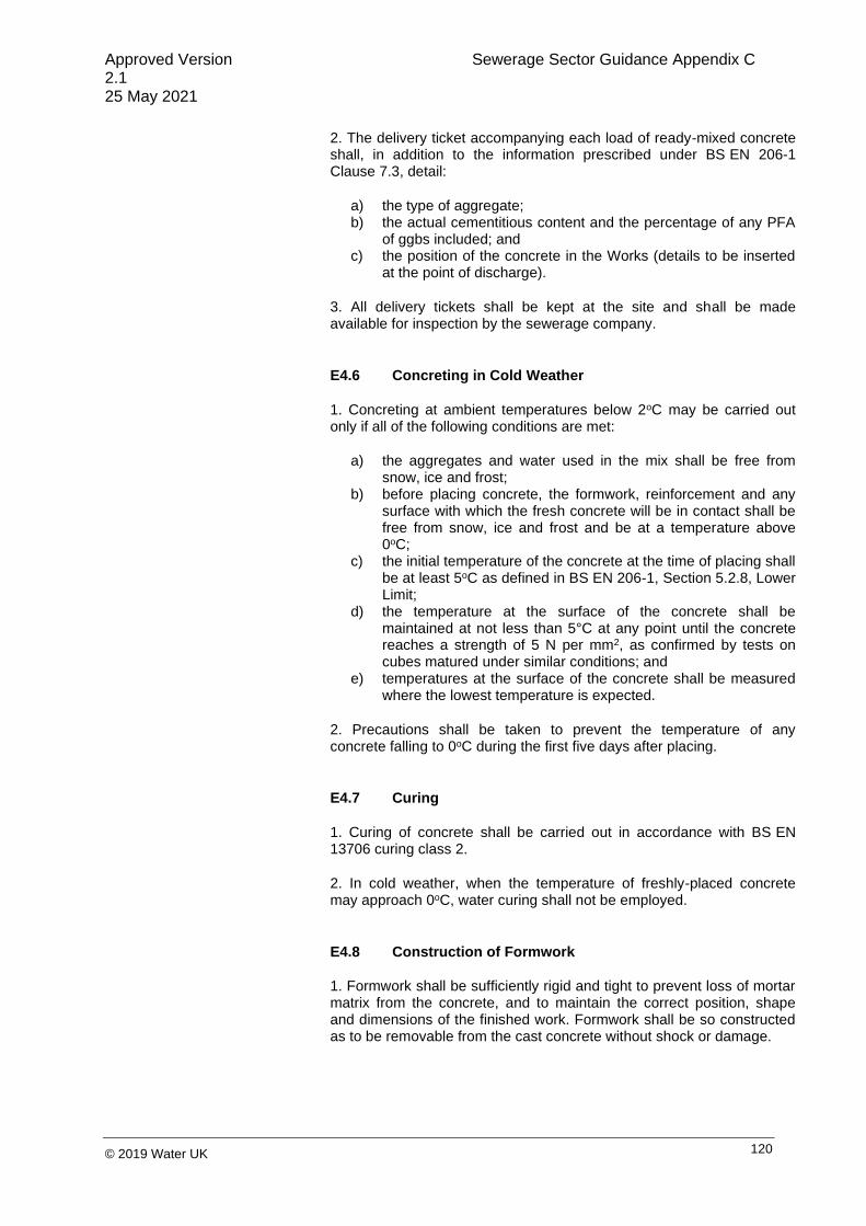
Approved Version Sewerage Sector Guidance Appendix C 2.1 25 May 2021
120 © 2019 Water UK
2. The delivery ticket accompanying each load of ready-mixed concrete shall, in addition to the information prescribed under BS EN 206-1 Clause 7.3, detail:
a) the type of aggregate; b) the actual cementitious content and the percentage of any PFA
of ggbs included; and c) the position of the concrete in the Works (details to be inserted
at the point of discharge).
3. All delivery tickets shall be kept at the site and shall be made available for inspection by the sewerage company.
E4.6 Concreting in Cold Weather
1. Concreting at ambient temperatures below 2oC may be carried out only if all of the following conditions are met:
a) the aggregates and water used in the mix shall be free from snow, ice and frost;
b) before placing concrete, the formwork, reinforcement and any surface with which the fresh concrete will be in contact shall be free from snow, ice and frost and be at a temperature above 0oC;
c) the initial temperature of the concrete at the time of placing shall be at least 5oC as defined in BS EN 206-1, Section 5.2.8, Lower Limit;
d) the temperature at the surface of the concrete shall be maintained at not less than 5°C at any point until the concrete reaches a strength of 5 N per mm2, as confirmed by tests on cubes matured under similar conditions; and
e) temperatures at the surface of the concrete shall be measured where the lowest temperature is expected.
2. Precautions shall be taken to prevent the temperature of any concrete falling to 0oC during the first five days after placing.
E4.7 Curing
1. Curing of concrete shall be carried out in accordance with BS EN 13706 curing class 2.
2. In cold weather, when the temperature of freshly-placed concrete may approach 0oC, water curing shall not be employed.
E4.8 Construction of Formwork
1. Formwork shall be sufficiently rigid and tight to prevent loss of mortar matrix from the concrete, and to maintain the correct position, shape and dimensions of the finished work. Formwork shall be so constructed as to be removable from the cast concrete without shock or damage.

Approved Version Sewerage Sector Guidance Appendix C 2.1 25 May 2021
121 © 2019 Water UK
E4.9 Cleaning and Treatment of Forms
1. The interiors of all forms shall be thoroughly cleaned out before any concrete is placed. The faces of the forms in contact with the concrete shall be clean and treated with a suitable release agent, where applicable.
E4.10 Striking of Formwork
1. Formwork shall be removed without shock to, or disturbance of, the concrete.
2. Formwork shall not be removed until the relevant periods given in Table E 12 have elapsed.
Type of Formwork Mean Ambient Temperature
15oC 5oC
Soffit forms to slabs and beams
5 days 7 days
Props to slabs and beams
10 days 15 days
Vertical 11 hours 24 hours
In cold weather, the period shall be increased in order to achieve the same minimum maturity at striking.
E4.11 Cutting and Bending of Reinforcement
1. Cutting and bending of reinforcement shall be in accordance with BS 8666 and shall be done without the application of heat, in a temperature of not less than 5oC. Bends shall have a substantially constant curvature.
2. Reinforcement shall not be straightened or re-bent without the agreement of the sewerage company. If permission is given to bend projecting reinforcement, care shall be taken not to damage the concrete and to ensure that the radius is not less than the minimum specified in BS 8666.
E4.12 Fixing of Reinforcement
1. Reinforcement shall be firmly supported in position and secured against displacement.
2. Non-structural connections for the positioning of reinforcement shall be made with tying wire or other fixing devices. Precautions shall be taken to ensure that projecting ends of ties or clips do not encroach into the concrete cover.
Table E 12

Approved Version Sewerage Sector Guidance Appendix C 2.1 25 May 2021
122 © 2019 Water UK
3. The concrete cover shall be not less than the minimum cover as specified in BS 8500-1, Clause 3.1.8, and where reinforcement is located in relation to only one face of a member, not more than the required cover plus:
a) 5 mm on bars up to and including 12 mm size; b) 10 mm on bars over 12 mm up to and including 25 mm size;
and c) 15 mm on bars over 25 mm size.
E4.13 Surface Condition of Reinforcement
1. Concrete shall not be placed until reinforcement is free from any substance which might adversely affect the steel or concrete chemically, or reduce the bond.
E4.14 Laps and Joints
1. Laps and joints in reinforcement shall be made only at the positions described on the Drawings.
E4.15 Built-in Items
1. Where pipes, sleeves, water bars or other items are built into concrete, they shall be rigidly secured in position to prevent movement and shall be free from external coatings which might adversely affect the bond.
2. Precautions shall be taken to prevent the formation of air pockets, voids or other defects whilst the concrete is being placed. When specifying a standard mix, the concrete shall be classed as reinforced if items are to be built into it.
E4.16 Construction Joints
(i) The Drawings should show the construction joints in the positions shown in the Figures included in this guidance.
1. Unless these are to be located in the positions shown on the typical detail Drawings (Figures B.13 to B.25), the positions and details of any construction joints shall be agreed with the sewerage company before work is commenced.
2. Concreting shall be carried out continuously up to construction joints.
E4.17 Surface Finishes Produced Without Formwork
1. Where a screeded finish is required, the concrete shall be levelled and screeded to produce a uniform plain or ridged surface, as required. No further work shall be applied to the surface unless it is a first stage for a steel trowel finish.
2. Where a steel trowel finish is required, then sufficient time shall elapse to allow the moisture film to disappear and the concrete to

Approved Version Sewerage Sector Guidance Appendix C 2.1 25 May 2021
123 © 2019 Water UK
harden sufficiently to prevent laitance from being worked to the surface. The concrete shall then be steel trowelled under firm pressure to produce a dense, smooth, uniform surface, free from trowel marks.
3. Where the type of finish is not given, it shall be screeded plain.
E4.18 Surface Finishes Produced with Formwork
1. Rough finish shall be used for surfaces which will not be visible on completion and shall be obtained by the use of moulds or properly-designed forms. The surface shall be free from substantial voids, honeycombing or other large blemishes.
2. Fair finish shall be used for surfaces which will be visible on completion and shall be obtained using forms designed to produce a hard, smooth surface with true, clean arises. Only very minor surface blemishes will be permitted and there shall be no staining or discolouration. Fins and other projections shall be removed and the surface made good.
E4.19 Tie Bolts for Formwork
1. Tie bolts or other devices to be built into concrete shall be approved by the sewerage company.
2. Tie bolts which form a continuous hole through a structural wall designed to retain an aqueous liquid shall not be used.
3. Tie bolts shall be of the high tensile variety and shall be cast directly into the concrete. Only tie bolts which avoid embedding any metal parts permanently within 50 mm of the concrete surface shall be permitted. Voids remaining after the removal of all, or part, of each tie bolt shall be filled flush with the surrounding concrete using a freshly-prepared cement and fine aggregate paste. All such voids shall be prepared by removing surface laitance prior to filling to ensure bond is achieved.
4. In the case of structures designed to retain an aqueous liquid, any other measures securing formwork shall not impair the watertightness of the structure.
E5 CONSTRUCTION OF GRAVITY SEWERS AND RISING MAINS
E5.1 General Construction
(i) The following publications give recommendations on standards of good practice for the installation of pipelines on land:
1. Where socketed pipes are required to be laid on a granular or sand bed or directly on a trench bottom, joint holes shall be formed in the bedding material or excavated formation to ensure that each pipe is uniformly supported throughout the length of its barrel and to enable the joint to be made.

Approved Version Sewerage Sector Guidance Appendix C 2.1 25 May 2021
124 © 2019 Water UK
‘
BS EN 752 ‘Drain and Sewer Systems Outside Buildings. Sewer System Management’;
BS EN 1610 ‘Construction and Testing of Drains and Sewers’; and
BS 8000-14 'Workmanship on Building Sites. Code of Practice for Below Ground Drainage'.
2. Pipes shall be laid on setting blocks only where a concrete bed or cradle is used.
3. Where pipes are required to be bedded directly on the trench bottom, the formation shall be trimmed and levelled to provide even bedding of the pipeline and shall be free from all extraneous matter that may damage the pipe, pipe coating or sleeving.
4. Pipes and fittings shall be examined for damage and the joint surfaces and components shall be cleaned immediately before laying.
5. Suitable measures shall be taken to prevent soil or other material from entering pipes, and each pipe shall be anchored to prevent flotation or other movement before the Works are complete.
6. Where pipeline marker tapes are specified, they shall be laid between 100 mm and 300 mm above the pipe. Where a tracer system is specified, it shall be continuous and adequately secured to valves and fittings.
E5.2 Pipe Bedding
(i) IGN 4-08-01 gives guidance on pipe surround materials.
(ii) Geotextile membranes may be an acceptable alternative to the use of clay stanks.
(iii) Full bed and surround may not be required for rigid, large diameter pipes. Reference should be made to manufacturer’s instructions.
1. Bedding for pipes shall be constructed by spreading and compacting granular bedding material over the full width of the pipe trench. After the pipes have been laid, additional granular material shall, if required, be placed and compacted equally on each side of the pipes and, where practicable, this shall be done in sequence with the removal of the trench supports.
2. Where in the opinion of the sewerage company the flow of groundwater is likely to transport fine soil particles, water stops of puddle clay extending up through the bedding and sidefill shall be placed across the trench and immediately downstream of any temporary works.
3. In bad ground conditions, where the migration of the pipe granular surround into the ground may occur or fines may be moved from the surround material into the bedding material causing a lack of support of the bedding, the surround shall be wrapped in geotextile membrane (see BS 9295 Clause A.13, Figures A.5 and A.6).
E5.3 Concrete Protection to Pipes
1. Pipes to be bedded on (or cradled with) concrete shall be supported on precast concrete setting blocks, the top face of each block being covered with two layers of compressible packing in accordance with E2.27.
2. Concrete provided as a protection to pipes shall be Grade GEN3 (C16/C20) complying with BRE Special Digest 1, placed to the required depth in one operation.

Approved Version Sewerage Sector Guidance Appendix C 2.1 25 May 2021
125 © 2019 Water UK
3. Where pipes with flexible joints are used, concrete protection shall be interrupted over its full cross-section at each pipe joint by a shaped compressible filler.
4. Where pipes are protected by a concrete cover slab placed above the pipe, this shall span the pipe trench and extend a minimum of 300 mm both sides, widening the trench above the pipe surround, and there shall be a minimum of 150 mm of surround between the crown of the pipe and underside of the slab, together with a layer of compressible material isolating the slab from the surround material.
E5.4 Pipe Surround
(i) Full bed and surround may not be required for rigid, large diameter pipes.
1. Pipe surround material shall, where required, be placed and compacted over the full width of the trench in layers not exceeding 150 mm before compaction, to a finished thickness of 300 mm above the crown of the pipes.
2. Subsequent backfilling shall then be carried out as specified in E3.4.
E5.5 Pipe Jointing Generally
(i) The remaining flexibility is required for any subsequent settlement or ground movement.
1. Pipe jointing surfaces and components shall be kept clean and free from extraneous matter until the joints have been made or assembled. Care shall be taken to ensure that there is no ingress of grout or other extraneous material into the joint annulus after the joint has been made.
2. Where, with the agreement of the sewerage company, rising mains are laid to curves, the deflection at any pipe joint as-laid shall not exceed three-quarters of the maximum deflection recommended by the manufacturer.
3. Site fusion jointing in polyethylene pressure pipelines shall be undertaken in accordance with the relevant provisions of WIS 4-32-08.
4. Where PE pipes are used for rising mains, a fully-welded system shall be used and the number of joints minimised. Mechanical or electrofusion joints shall not be used unless expressly specified.
5. Proprietary joints shall be made in accordance with the manufacturer’s instructions.
E5.6 Cutting Pipes
1. Pipes shall be cut in accordance with the manufacturer’s recommendations to provide a clean square profile without splitting or fracturing the pipe wall and causing minimal damage to any protective coating. Where necessary, the cut ends of pipes shall be formed to the tapers and chamfers suitable for the type of joint to be used.

Approved Version Sewerage Sector Guidance Appendix C 2.1 25 May 2021
126 © 2019 Water UK
2. Where ductile iron pipes are to be cut to form non-standard lengths, the manufacturer’s recommendations in respect of ovality correction and tolerances to the cut spigot end shall be complied with.
3. Where concrete pipes are cut, any exposed reinforcement shall be sealed with an epoxy-resin mortar.
4. Pre-stressed concrete pipes shall not be cut on site.
5. Particular safety precautions shall be taken to avoid inhalation of dust when cutting asbestos-cement pipes.
E5.7 Thrust Block
(i) Thrust blocks should either be shown on the Drawings or constructed in accordance with the sewerage company’s instructions on-site.
(ii) Plastics pipes should be separated from thrust blocks by plastic sheeting so as to minimise the risk of stress concentrations and abrasion where the pipe emerges from the thrust block.
1. Except where self-anchoring joints are used, thrusts from bends and branches in rising mains shall be resisted by GEN3 concrete thrust blocks, cast in contact with undisturbed ground.
2. Any additional excavation required to accommodate thrust blocks shall be carried out after the bend or branch is in position, and the thrust face shall be trimmed back to remove all loose or weathered material immediately prior to concreting.
3. Thrust blocks shall be allowed to develop adequate strength before any internal pressure is applied to the rising main.
4. Where rapid hardening is used in concrete for the protection of plastics pipes, an assessment and provision shall be made to protect pipes from any excessive heat that may be generated during the curing reaction.
5. Plastics pipes shall be wrapped with three layers of plastic sheeting complying with E2.17.1 before being surrounded by concrete.
E5.8 Connections to Gravity Sewers
1. Where junction pipes for future connections are required, they shall be inserted, as necessary, during construction of the sewers, and the ends of connections and pipes not needed for immediate use shall be effectively sealed with a plug. The position of all junctions shall be recorded by measurement from the centre of the manhole cover immediately downstream, and notified to the sewerage company before backfilling is carried out.
2. Connections shall be made using standard pre-formed junctions, where possible. Saddle connections to existing sewers shall only be allowed when the internal diameter of the major pipe is at least 150 mm greater than the internal diameter of the branch pipe.
3. Pipe saddles for concrete or clay sewers shall be bedded in Class M1 mortar and a mortar fillet formed to give a cover of at least 50 mm to the base of the saddle.

Approved Version Sewerage Sector Guidance Appendix C 2.1 25 May 2021
127 © 2019 Water UK
E5.9 Tolerances in Gravity Sewers, Lateral Drains and Rising Mains
(i) Lines and levels for sewers, lateral drains and rising mains should be as shown on the Drawings.
1. The position of the internal face of any sewer, lateral drain or rising main shall not deviate from the line and level described in the Agreement, or agreed variation, by more than ± 20 mm.
2. No pipe in a sewer or lateral drain shall have a reverse gradient.
3. The joint displacement, being the difference in level or alignment between the adjacent ends of two adjoining pipes at a joint, shall not exceed the least of 5% of the nominal diameter of the pipe or 20 mm.
4. The angular displacement at a joint, being the difference in the alignment of two adjacent pipes, shall not exceed 2° except where the joint has been specifically designed and manufactured to accommodate a larger displacement.
5. Flexible pipes shall have a limit of 6% deformation.
6. Where a fitting is installed on a sewer length, it shall have the same internal bore as the sewer.
E6 CONSTRUCTION OF MANHOLES, INSPECTION CHAMBERS AND WET WELLS
E6.1 Brickwork and Blockwork
(i) The term "blocks" has been used for precast concrete masonry units (see E2.39).
(ii) Flush jointing is described in BS EN 1996-1-2, BS EN 1996-2 and BS EN 1996-3.
1. Brickwork and blockwork shall comply with the relevant provisions of BS EN 1996-1-2, BS EN 1996-2 and BS EN 1996-3.
2. Brickwork and blockwork shall be built in English bond. Bricks and blocks shall be set in mortar with all bed and vertical joints filled solid. Exposed work shall be flush pointed as the work proceeds. The moisture content of the bricks and blocks shall be adjusted so that excessive suction is not exerted on the mortar.
3. Bricks and blocks in each course shall break joint correctly with the bricks/blocks underneath. The courses shall be laid parallel, with joints of uniform thickness, and shall be kept straight or regularly curved, as required. Brickwork and blockwork shall be gauged to rise 300 mm in four courses. Vertical joints shall be in alignment, as required by the bond, and shall have an average thickness of 10 mm. Bricks and blocks forming reveals and internal and external angles, shall be selected for squareness and built plumb.

Approved Version Sewerage Sector Guidance Appendix C 2.1 25 May 2021
128 © 2019 Water UK
4. Brickwork and blockwork shall rise uniformly. Corners and other advanced work shall be racked back and not raised above the general level more than 1 m. No brickwork or blockwork shall be carried up higher than 1.5 m in one day. No bats or broken bricks and blocks shall be incorporated in the work unless essential for bond. Where cuts to blocks are required, all cutting shall be carried out with a mechanical cutting disc.
5. Completed brickwork and blockwork shall be protected at all times from scaffold splash, mortar droppings, grout leakage from suspended slabs and the harmful effects of weather. Brickwork and blockwork shall be allowed to set thoroughly hard before cutting or chasing is carried out.
E6.2 Corbelling
1. Oversail corbelling shall not exceed 30 mm on each course.
E6.3 Bricklaying and Blocklaying in Cold Weather
1. Materials used in bricklaying and blocklaying shall be frost-free, and no bricks or blocks shall be laid when the ambient temperature is below 3oC, unless special precautions are taken. Completed work shall be protected adequately during cold weather.
2. General working practices shall be in accordance with the Brick Development Association publication ‘Bricklaying in Winter Conditions’.
E6.4 Precast Concrete Manholes, Chambers and Wet Well
1. Precast concrete chamber unit sections for manholes shall be constructed with steps, ladders and slabs aligned correctly.
2. The jointing material for precast units shall be mortar, proprietary plastomeric or elastomeric seal with load bearing distribution, with the concrete surfaces prepared in accordance with the manufacturer’s recommendations.
3. Joints made with plastomeric sealant or mortar shall be made so that the required jointing material fills the joint cavity. Concrete to concrete contact across the joint shall not be permitted. Any surplus jointing material which is extruded inside the manhole, chamber or wet well shall be trimmed off and joints shall be pointed on completion.
4. Concrete surrounds to manholes, chambers and the wet wells, where required, shall be Grade GEN3 complying with ‘BRE Special Digest 1’. The height of each concrete pour shall not exceed 2 m. Each construction joint shall break joint with the precast sections by at least 150 mm.
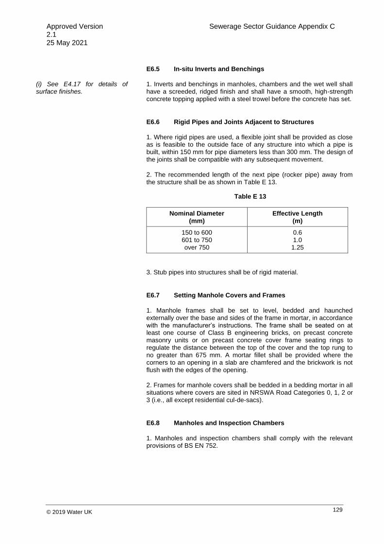
Approved Version Sewerage Sector Guidance Appendix C 2.1 25 May 2021
129 © 2019 Water UK
E6.5 In-situ Inverts and Benchings
(i) See E4.17 for details of surface finishes.
1. Inverts and benchings in manholes, chambers and the wet well shall have a screeded, ridged finish and shall have a smooth, high-strength concrete topping applied with a steel trowel before the concrete has set.
E6.6 Rigid Pipes and Joints Adjacent to Structures
1. Where rigid pipes are used, a flexible joint shall be provided as close as is feasible to the outside face of any structure into which a pipe is built, within 150 mm for pipe diameters less than 300 mm. The design of the joints shall be compatible with any subsequent movement.
2. The recommended length of the next pipe (rocker pipe) away from the structure shall be as shown in Table E 13.
Nominal Diameter (mm)
Effective Length (m)
150 to 600 601 to 750 over 750
0.6 1.0 1.25
3. Stub pipes into structures shall be of rigid material.
E6.7 Setting Manhole Covers and Frames
1. Manhole frames shall be set to level, bedded and haunched externally over the base and sides of the frame in mortar, in accordance with the manufacturer’s instructions. The frame shall be seated on at least one course of Class B engineering bricks, on precast concrete masonry units or on precast concrete cover frame seating rings to regulate the distance between the top of the cover and the top rung to no greater than 675 mm. A mortar fillet shall be provided where the corners to an opening in a slab are chamfered and the brickwork is not flush with the edges of the opening.
2. Frames for manhole covers shall be bedded in a bedding mortar in all situations where covers are sited in NRSWA Road Categories 0, 1, 2 or 3 (i.e., all except residential cul-de-sacs).
E6.8 Manholes and Inspection Chambers
1. Manholes and inspection chambers shall comply with the relevant provisions of BS EN 752.
Table E 13

Approved Version Sewerage Sector Guidance Appendix C 2.1 25 May 2021
130 © 2019 Water UK
E7 CLEANSING AND TESTING
E7.1 Cleansing of Gravity Sewers and Manholes
(i) The action to be taken in the event of failure to satisfy the tests specified has only been referred to in general terms where the text so requires (see also E1.3).
1. On completion of construction, internal surfaces of sewers, manholes and other access points shall be thoroughly cleansed to remove all deleterious matter, without such matter being passed forward into existing public sewers or watercourses. The sewers and manholes shall be maintained in a clean and serviceable condition until they are vested as public sewers.
E7.2 Precautions Prior to Testing Rising Mains
(i) Testing against a closed valve in a rising main should not be permitted if there is any other alternative.
(ii) For notification of intention to test, see E1.4.2.
(iii) See also E5.7.
1. Before testing any rising main, it shall be ensured that it is anchored adequately and that thrusts from bends, branch outlets or from the pipeline ends, are transmitted to solid ground or to a suitable temporary anchorage.
2. Open ends shall be stopped with plugs, caps or blank flanges properly jointed.
3. Testing against closed valves shall not be permitted.
E7.3 Testing of Gravity Sewers
(i) Visual examination may include the use of CCTV and/or light-line inspections.
1. Sewers up to and including 1000 mm nominal diameter shall be tested by means of an air or water test.
2. Sewers shall be tested regularly throughout the installation (typically every three jointed segments) before any concreting or backfilling is commenced, other than such as may be necessary for structural stability whilst under test.
3. An air test shall be carried out after the backfilling is complete.
4. The pipelines shall be inspected by means of a visual or closed-circuit television (CCTV) examination, in lengths determined by the course of construction.. For flexible pipes, the CCTV examination shall use light rings to measure deformations.

Approved Version Sewerage Sector Guidance Appendix C 2.1 25 May 2021
131 © 2019 Water UK
E7.4 Air Test for Gravity Sewers
(i) BS EN 1610 ‘Construction and Testing of Drains and Sewers’ gives advice on testing requirements.
1. Sewers to be air tested, including adopted laterals up to demarcation chambers, shall have air pumped in by a suitable means until a pressure of 100 mm head of water is indicated in a U-tube connected to the system. The sewer shall be accepted if the air pressure remains above 75 mm head of water after a period of five minutes without further pumping, following a period for stabilisation. Failure to pass the test shall not preclude acceptance of the pipeline if a successful water test can subsequently be carried out in accordance with E7.5.
E7.5 Water Test for Gravity Sewers
1. The test pressure for sewers shall not be less than 1.2 m head of water above the pipe soffit or groundwater level, whichever is the higher, at the highest point, and not greater than 6 m head at the lowest point of the section. Steeply-graded sewers shall be tested in stages in cases where the maximum head, as stated above, would be exceeded if the whole section were tested in one length.
2. The sewer shall be filled with water and a minimum period of two hours shall be allowed for absorption, after which water shall be added from a measuring vessel at intervals of five minutes and the quantity required to maintain the original water level noted, following which the original water level shall be restored. Unless otherwise specified, the length of sewer shall be accepted if the quantity of water added over a 30-minute period is less than 0.5 litres per linear metre of sewer per metre of nominal diameter.
3. Notwithstanding the satisfactory completion of the above test, if there is any discernible leakage of water from any pipe or joint, the pipe shall be replaced and/or the joint re-made, as appropriate, and the test repeated until leakage is stopped.
E7.6 Visual Inspection of Gravity Sewers
(i) A visual survey may include the use of CCTV and/or internal survey, or walk-through inspection.
(ii) The ratio described in E7.6.2 can be written in shorthand as:
∅ max − ∅ 𝑚𝑖𝑛
∅ 𝑚𝑎𝑥
1. A visual survey shall be carried out by a qualified and approved contractor, and in accordance with the ‘Model Contract Document for Sewer Condition Inspection’, 2nd edition.
2. Light ring survey equipment shall be calibrated to measure the cross-sectional dimensions and the pipe ovality to within ± 1%, where ovality is defined as the ratio between the difference between the maximum internal diameter and the mean internal diameter, and the mean internal diameter.

Approved Version Sewerage Sector Guidance Appendix C 2.1 25 May 2021
132 © 2019 Water UK
E7.7 Infiltration
(i) The permissible infiltration is the same as the permissible loss in the water test in E7.5.
(ii) Infiltration rate is based on
the 0.15 calculation included in BS EN 1610.
1. Non-pressure pipelines and manholes shall be inspected and tested for infiltration of groundwater into the pipeline after backfilling. All inlets to the system shall be effectively closed and any residual flow shall be deemed to be infiltration.
2. The pipeline and manholes shall be accepted as satisfactory if the infiltration, including infiltration into manholes, in 30 minutes does not exceed 0.5 litres per linear metre of pipeline per metre of nominal bore.
3. Notwithstanding the satisfactory completion of the above inspection or test, if there is any discernible flow of water entering the sewers or manholes which can be seen either by visual or CCTV inspection, such measures as are necessary to stop such infiltration shall be taken.
(i) BS EN 1610 ‘Construction and Testing of Drains and Sewers’ gives advice on testing requirements.
E7.8 Watertightness of Manholes, Inspection Chambers and Wet Wells
1. These shall be inspected to ensure that they are watertight with no identifiable flow of water penetrating the chamber.
E7.9 Testing of Ductile Iron, GRP and Steel Pressure Pipelines
(i) This section is intended for application to rising mains materials such as ductile iron.
(ii) A large-diameter pressure gauge has been specified to enable a small change in pressure to be accurately measured.
1. The entire pipeline shall be pressure tested in accordance with BS EN 805 or IGN 4-01-03.
2. Rising mains shall be tested after they are jointed and before any concreting or backfilling is commenced, other than such as may be necessary for structural stability whilst under test.
3. Gauges used for testing rising mains shall either be of the conventional circular type, not less than 200 mm diameter, calibrated in metres of head of water, or shall have a digital indicator capable of reading increments of 0.1 m head. Before any gauge is used, it shall be checked independently and a dated certificate of its accuracy shall be provided. After having been filled, pipelines shall be left under normal operating pressure for 24 hours, so as to achieve conditions as stable as possible for testing.
4. Before testing, valves shall be checked and sealed, the sections of main filled with water and the air released.
5. The pressure in the rising main shall then be raised steadily until the specified test pressure is reached in the lowest part of the section. The pressure shall be maintained at this level, by pumping if necessary, for a period of at least one hour. The pump unit shall then be disconnected, and no further water shall be permitted to enter the rising main for a further period of one hour. At the end of this period, the original pressure shall be restored by pumping and the loss measured by drawing off water from the main until the pressure as at the end of the test, is again reached.

Approved Version Sewerage Sector Guidance Appendix C 2.1 25 May 2021
133 © 2019 Water UK
6. The permissible loss shall not exceed 2 litres per metre nominal bore per kilometre length per metre head (calculated as the average head applied to the section) per 24 hours.
7. The developer shall provide, and subsequently dispose of, the water required for the test. Discharges to sewers shall not take place without the consent of the sewerage company.
8. Test pressures for rising mains shall be 1.5 times the maximum operating pressure at the lowest point of the main, or the maximum operating pressure plus the maximum calculated surge pressure, whichever is the greater.
9. Where a new pipeline is to connect to an operational pipeline, the final connection shall be inspected visually under normal operating pressure and there shall be no visible leakage.
E7.10 Testing of Polyethylene Pressure Pipelines
1. Clauses E7.9.1, E7.9.2, E7.9.3, E7.9.4, and E7.9.7 shall apply.
2. The testing of polyethylene pressure pipelines shall be carried out in accordance with IGN 4-01-03.

Approved Version Sewerage Sector Guidance Appendix C 2.1 25 May 2021
134 © 2019 Water UK
Approved Version Sewerage Sector Guidance Appendix C 2.1 25 May 2021
135 © 2019 Water UK
PART F – MECHANICAL AND ELECTRICAL SPECIFICATION FOR SMALL PUMPING
STATIONS
Appendix F

Approved Version Sewerage Sector Guidance Appendix C 2.1 25 May 2021
136 © 2019 Water UK
INTRODUCTION
1. Part F of this guidance is the Mechanical and Electrical Specification to support Part D. As such, the
scope of Part D (see D1) applies here. If pumping stations include any pump unit rated over 30 kW,
different specifications may apply and detailed discussions should be held with the sewerage company
at an early stage.
F1 GENERAL
F1.1 Hazardous Area Appliances
1. All electrical and mechanical equipment selected for use in a hazardous area shall have undergone
an appropriate conformity assessment procedure (CAP) to demonstrate compliance with the essential
health and safety requirements of European Directive 94/9/EC (ATEX 95), as enacted in the UK by the
Equipment and Protective Systems Intended for Use in Potentially Explosive Atmospheres Regulations
2016.
2. If a pump unit will operate in a hazardous area classified as Zone 1 or 2, all electrical and mechanical
equipment shall be selected in accordance with the relevant parts of BS EN 60079 and the relevant
parts of BS EN 13463 or BS EN ISO 80079, as appropriate.
3. Appropriate certification shall be included in the pumping station O&M manuals to confirm the
suitability of the electrical and mechanical equipment for operation in the specified hazardous area(s).
Risk assessments shall be carried out in accordance with BS EN 1127-1 ‘Explosive Atmospheres.
Explosion Prevention and Protection. Basic Concepts and Methodology’ and any requirements from the
sewerage company. Any certification, manuals, etc., shall be in accordance with the sewerage
company’s requirements.
F1.2 Operation and Maintenance Documentation
1. Operation and maintenance documentation for all equipment shall be provided together with as-built
drawings and operational manuals for the pumping station.
F2 PUMP UNIT SPECIFICATION
F2.1 Introduction
1. The pumping station shall incorporate two identical submersible pump units arranged in a
duty/standby configuration.
2. The pump units shall be of the single stage, centrifugal, volute type, suitable for pumping untreated
sewage containing fibrous and stringy material (rags, paper, etc.), solid faecal matter and grit.
3. The pump units shall comply with all relevant Statutory Regulations and the latest editions of all
relevant International, harmonised European and British Standards.

Approved Version Sewerage Sector Guidance Appendix C 2.1 25 May 2021
137 © 2019 Water UK
F2.2 Performance Requirements and Information
1. Wherever possible, the maximum operating speed of the pump units shall not exceed 1500 rpm.
Where, for a Type 1 or 2 pumping station, a higher operating speed is necessary, evidence shall be
provided to justify the selection of higher speed pump units.
Note: The evidence to justify the selection of higher speed pump units shall be provided prior to their
purchase.
2. Each pump unit shall be capable of pumping the design flow rate when the sewage level is at the
mid-point of the start and stop levels in the wet well.
3. The net positive suction head (NPSH) available shall be at least 2.0 m greater than the NPSH
required. The NPSH available shall be calculated at all points on the system curve to ensure that
cavitation and vibration does not occur during pump unit operation.
4. The pumps and their drive motors shall be suitably rated to allow for increased head due to expected
sliming/fatting-up/scaling and deterioration of pipe material of the rising main, during the lifetime of the
pump unit.
5. The pump units shall be capable of continuous operation within the design operating envelope
including (where appropriate and in accordance with any hazardous area rating) being run on a regular
basis for short periods of time "on snore" to keep the wet well free from silt.
6. The pump units shall have stable head versus flow rate characteristics against the system curve(s)
(i.e., each pump unit’s head versus flow rate curve shall slope upwards towards closed valve with
reducing flow rate in one continuous curve, with no points of inflection capable of causing hunting when
considered against the system curve(s)).
7. Wherever possible, the pump units shall be selected such that the design flow rate is between 80%
and 105% of the pump unit best efficiency point (BEP) flow rate. Where this is not possible, evidence
shall be provided to show that the most efficient pump units have been selected for the duty.
Note: The evidence to show that the most efficient pump units have been selected shall be provided
prior to their purchase.
8. The pump units shall be capable of discharging into an empty main.
9. The pump units shall be capable of operating against a closed valve for up to two minutes.
10. The maximum diameter of solid sphere able to be passed by the pump units shall generally be in
accordance with the guidelines given in Table F 1.
Note: Where the pump units feature an innovative design which does not allow compliance with
Table F 1, then prior to purchase of the pump units, substantiating information shall be provided (for

Approved Version Sewerage Sector Guidance Appendix C 2.1 25 May 2021
138 © 2019 Water UK
approval) to demonstrate that the solids handling performance of the pump units will satisfy the relevant
requirements (i.e., the pump units will be capable of prolonged, reliable and trouble-free operation).
Table F 1 Solids Handling Performance
Nominal Bore of Outlet (mm)
Diameter of Solid Sphere Able to be Passed (mm)
Type 3 Pumping Stations
Types 1 and 2 Pumping Stations
80 60 60
> 80 but < 100 75 65
> 100 but < 125 90 90
> 125 but < 175 120 120
11. The pump units shall be reliable, efficient and capable of operating between the manufacturer’s
recommended service intervals without attention or inspection. Pump units shall have an expected
design life of 20 years when maintained in accordance with the manufacturer’s recommendations.
F2.3 Design Requirements
F2.3.1 Materials selection
1. Pump unit materials shall be selected with reference to the operating environment, pumped liquid
and expected design life. Where there is a risk of saline ingress into the wet well, pump unit materials
shall be selected accordingly.
2. Where surfaces (such as stainless steel wear rings) may be subject to galling, materials shall be
selected to minimise wear and have a minimum hardness differential of 50 HB.
F2.3.2 External corrosion protection
1. Protective coatings shall be selected with reference to the operating environment, pumped liquid and
expected design life.
F2.3.3 Noise
1. The noise levels from each pump unit shall not exceed 80 dB(A) at a distance of 1 m from the pump
unit centreline (based on the pump unit being mounted in "semi-reverberant" conditions).
F2.3.4 Mounting arrangements
F2.3.4.1 Guide system
1. The pump units shall be positively guided during installation and removal from the wet well by a
guide system.

Approved Version Sewerage Sector Guidance Appendix C 2.1 25 May 2021
139 © 2019 Water UK
2. The guide system shall be designed and installed to ensure straight, vertical lifting/lowering of the
pump units.
3. The guide system shall allow the pump units to be raised to the top of the wet well without the need
to undo any fixing arrangements or enter the wet well.
4. The guide system shall comprise twin circular cross-section tubes and all necessary fixtures and
fixings. Guide wires shall not be used.
5. All guide tubes, brackets and fasteners (i.e., nuts, bolts, etc.) shall be made from stainless steel
number 1.4401 to BS EN 10088-1.
6. The guide tubes shall be of single piece construction and shall be supported along their length by
suitably-designed brackets. The maximum length of any unsupported guide tube span shall be 3 m.
The tops of the guide tubes shall finish a maximum of 150 mm below the underside of the wet well
cover.
F2.3.4.2 Auto-coupling system (ACS)
1. Each pump unit shall be provided with an auto-coupling system (ACS) to interface it with the outlet
pipework/rising main. The following requirements shall apply:
a) the ACS shall typically comprise a duck-foot bend, guide claw and all necessary
seals/gaskets and fixings;
b) all fixings shall be manufactured from stainless steel number 1.4401 to BS EN 10088-1 and, if
necessary, be provided with suitable galvanic isolation;
c) the outlet connection of the duck-foot bend shall terminate with flange type PN16;
d) the ACS shall be designed so that the pump unit is positively located onto the duck-foot bend
during pump installation;
e) the ACS shall be designed so that the interface between the duck-foot bend and guide claw is
effectively sealed during pump installation;
f) the duck-foot bend shall include suitable provisions for locating and fixing the guide tubes
and, if necessary, shall be galvanically isolated from the guide tubes; and
g) the duck-foot bend shall include suitable provisions for securing it to the base of the wet well.
F2.3.5 Pump casings
1. Casings shall be capable of withstanding any pressure or dynamic loading that may be generated
during normal pump operation, including intermittent physical shock loadings caused by solids in the
flow.
2. The outlet connection of each pump unit shall terminate with flange type PN16, in accordance with
BS EN 1092-2.
3. All casing surfaces having a fine clearance between fixed and rotating components shall be provided
with renewable wear parts that are easily removable for refurbishment or replacement.

Approved Version Sewerage Sector Guidance Appendix C 2.1 25 May 2021
140 © 2019 Water UK
4. The direction of rotation of the impeller shall be clearly and indelibly marked on the pump unit
casings with an arrow.
F2.3.6 Impellers
1. Impellers shall be selected to prevent fouling, allow the passage of fibrous, stringy and solid
materials, and suit the operating conditions in an efficient manner.
2. If possible, the pump units shall not be fitted with the minimum or maximum sized impellers for the
selected casing size.
3. Impellers shall be one-piece castings.
4. Impellers shall not be pinned or screwed to shafts, nor shall shaft rotation be relied upon to ensure
that impellers are locked in position. Impellers shall be capable of running in the reverse direction (e.g.,
under de-ragging control).
5. To achieve acceptable vibration performance, impellers shall be balanced. Multi-vane and
vortex impellers shall be balanced to a minimum of balance grade G6.3 of BS ISO 21940-11 (balancing
shall be achieved by machining not by the addition of weights).
6. All impeller surfaces having a fine clearance between fixed and rotating components shall be
provided with renewable wear parts that are easily removable for refurbishment or replacement.
F2.3.7 Shafts
1. Pump shafts shall be sized to accommodate all possible loads over the operating range of the pump,
including starting direct-on-line (DOL).
2. The first critical speed of the rotating elements (i.e., the shaft, motor rotor and impeller, etc.) shall be
at least 25% above the maximum operating speed.
3. The shaft stiffness shall be such that, under the most severe conditions of operation, the total shaft
deflection at the seals does not exceed the seal manufacturer’s specified tolerances.
4. If the shaft is exposed to the pumped sewage, it shall be manufactured from a corrosion-resistant
material or be protected by a stainless steel (number 1.4401 to BS EN 10088-1) sleeve.
5. Shaft sleeves (where provided) shall:
a) be manufactured from a material that will not cause galvanic corrosion between itself and the
shaft;
b) be positively driven (i.e., keyed or pinned to the shaft); and
c) incorporate O-ring seals to prevent leakage of the pumped sewage between shafts and
sleeves.

Approved Version Sewerage Sector Guidance Appendix C 2.1 25 May 2021
141 © 2019 Water UK
F2.3.8 Seals
1. Sealing between the casing volute and motor enclosure shall be achieved by primary (casing volute
to buffer chamber) and secondary (buffer chamber to motor enclosure) mechanical seals and by a fluid-
filled chamber between the primary and secondary seals.
2. Where the pump units feature an innovative sealing arrangement that does not incorporate a fluid-
filled chamber, substantiating information shall be provided (for approval) to demonstrate that this
sealing arrangement will satisfy the necessary requirements. This information shall be provided before
pump units are purchased.
3. Stationary and rotating rings shall be composed of a single material, i.e., wear-resistant coatings
shall not be used.
4. Seal component materials shall be compatible with the pumped sewage.
F2.3.9 Bearings and bearing lubrication
1. Rotating assemblies (motor rotor, shaft and impeller) shall be supported by grease-lubricated upper
and lower rolling element bearings.
2. Bearings shall be rated for a minimum L10h life of 50,000 hours at the design operating conditions.
F2.3.10 Motors
F2.3.10.1 General
1. Motors shall be capable of continuous operation under the operating conditions of the pump unit.
2. Where downstream requirements suggest variable speed drives may be required, the design shall be
submitted to the sewerage company for approval before construction.
F2.3.10.2 Electrical supply
1. Motors shall be suitable for the site electrical supply, see F3.2.1.2.
F2.3.10.3 Duty and rating
1. Each motor shall have a maximum continuous (MC) rating, based on duty type S1 (as defined in
BS EN 60034-1), equal to at least 110% of the maximum pump power input over its operating range.
F2.3.10.4 Starting
1. Motors shall be capable of handling a maximum of 15 starts per hour.

Approved Version Sewerage Sector Guidance Appendix C 2.1 25 May 2021
142 © 2019 Water UK
F2.3.10.5 Enclosure and cooling
1. Motors shall have an enclosure classification of IP68 in accordance with BS EN 60529 and be
suitable for operation whilst continuously submerged to a depth of 20 m.
2. Motors shall incorporate a cooling system that will allow the pump units to run, without de-rating, over
their full operating range. If the cooling system incorporates an integral cooling jacket, this shall be of
the integral recirculation type and shall not utilise the process media.
F2.3.10.6 Insulation
1. The motor insulation class, in accordance with BS EN 60085 (i.e., F, G, H, etc.), shall be at least one
class higher than the temperature rise limit, in accordance with BS EN 60034-1, as measured by the
resistance of the windings during full load operation, subject to a minimum insulation class of Class F.
F2.3.11 Information plate
1. Each pump unit shall be provided with an information plate, permanently fixed to the pump unit. The
plate and its fixings shall be manufactured from corrosion-resistant metallic materials. As a minimum,
the information plate shall include the following information:
a) pump unit manufacturer;
b) pump unit type;
c) pump unit serial number;
d) impeller number or diameter;
e) flow rate at the duty point (litres per second);
f) head at the duty point (m);
g) operating speed (rpm);
h) motor rating (kW);
i) operating voltage (V), number of phases and frequency (Hz);
j) full load current (A);
k) full load power factor;
l) insulation class;
m) enclosure classification (IP rating);
n) hazardous area classification; and
o) pump unit weight.
2. Duplicate information plates shall be provided and labelled "Pump No. 1" and "Pump No. 2". These
shall be positioned adjacent to the electrical assembly in a clearly-visible location.
F2.3.12 Pump unit lifting points
1. Each pump unit shall be provided with clearly-identified, permanent, corrosion-resistant lifting points,
located to give a safe, balanced lift.
2. Lifting points shall be designed for lifting the whole pump unit.

Approved Version Sewerage Sector Guidance Appendix C 2.1 25 May 2021
143 © 2019 Water UK
3. The pump unit shall incorporate a lifting handle. The following requirements shall apply:
a) the handle material shall be made from stainless steel number 1.4401 to BS EN 10088-1. If
the handle is not an integral part of the pump casing, it shall be secured to the pump casing
using fasteners manufactured from stainless steel number 1.4401 to BS EN 10088-1 and be
provided with suitable galvanic isolation;
b) the handle shall be designed to ensure that the nose of the lifting hook does not sit on the
underside of the handle during lifting, i.e., it shall have a "round", "V-shaped" or "convex"
profile; and
c) the shape of the lifting handle shall ensure that a minimum clearance of 250 mm is provided
from the top of the pump unit to the underside of the handle to facilitate location of the
sewerage company’s lifting hook during lifting.
F2.3.13 Pump unit cables
1. Each pump unit shall be supplied and fitted with a cable of a suitable length for the duty.
2. Cables shall be suitably rated for the duty, be constructed in accordance with BS EN 50525 with oil-
and weather-resistant chloroprene rubber (or equivalent) sheathing, and comprise power and auxiliary
cables necessary for the motor supply and all protection circuits.
3. Each cable shall incorporate an earth conductor.
F2.3.14 Pump unit lifting arrangements
F2.3.14.1 General
1. All lifting equipment (including attachments for anchoring, fixing or supporting the lifting equipment)
and lifting accessories (chains, eyebolts, etc.) shall comply with the Lifting Operations and Lifting
Equipment Regulations (LOLER) and the Provision and Use of Work Equipment Regulations
(PUWER).
2. All individual items of lifting equipment and lifting accessories shall be visibly and indelibly marked
(i.e., stamped or painted) with the following:
a) their safe working loads (SWL);
b) the lifting equipment/accessory serial number; and
c) the date of the next "thorough" examination of the lifting equipment/accessory, in accordance
with LOLER. This date will change on a regular basis and so shall be indelibly marked on a
replaceable component (e.g., a cable tie).
3. The following information shall be provided in relation to all lifting equipment and lifting accessories:
a) the original test certificate;
b) an EC "Declaration of Conformity", from the lifting equipment/accessory manufacturer; and
Approved Version Sewerage Sector Guidance Appendix C 2.1 25 May 2021
144 © 2019 Water UK
c) a "Report of Thorough Examination", in accordance with LOLER. If, at the time of adoption of
the pumping station, there is less than six months from the date of the "Report of Thorough
Examination" until the next inspection, then a further examination shall be undertaken by the
developer.
All of the above information shall be in accordance with the sewerage company’s requirements and
copies shall be inserted in the pumping station O&M manuals.
4. Pump units shall be provided with a proprietary lifting chain location system if all of the following
criteria are satisfied:
a) the wet well is less than or equal to 6 m in depth;
b) the weight of each pump unit is less than or equal to 500 kg; and
c) the pump unit lifting handle is of a suitable design to accept the sewerage company’s
standard lifting hook (refer to F2.3.12).
5. If any of the above criteria are not satisfied, lifting chains shall be provided, permanently fixed within
the wet well.
F2.3.14.2 Lifting chain location system
1. Where provided, the lifting chain location system shall comprise two 6 mm diameter, non-degradable
cords. Each cord shall be threaded through its associated pump unit lifting handle and both of its ends
shall be secured at opposite sides of the wet well access point with stainless steel number 1.4401 to
BS EN 10088-1 swivel hooks with integral safety catches.
F2.3.14.3 Lifting chains
1. Where provided, chains shall be of the short-link type to BS EN 818-1 and BS EN 818-3.
2. To assist in lifting, chains shall incorporate larger links with a minimum internal diameter of 50 mm,
spaced at a maximum of 1 m intervals along their length.
3. Chains shall be rated to lift twice the weight of each pump unit, subject to a minimum SWL of 500 kg.
4. Where the chains remain attached to the pump units during pump unit operation, they shall be
securely fixed to the pump units with stainless steel D shackles. Suitable measures shall be taken to
ensure that the D shackles do not loosen and are not damaged/worn due to pump unit vibration,
e.g., by using extended pins and nyloc nuts.
5. The loose ends of the chains shall be attached to a stainless steel hook, fixed to the underside of the
wet well cover to enable access without leaning out over the wet well.
6. The length of the chains shall be such that when the pump units are in position, the chains extend at
least 1 m above the top of the wet well.

Approved Version Sewerage Sector Guidance Appendix C 2.1 25 May 2021
145 © 2019 Water UK
7. A stainless steel identification tag, detailing the information specified in F2.3.14.1.2 shall be securely
attached to the top end of each chain.
8. Chains, links, hooks, D shackles and identification tags shall be made from stainless steel number
1.4401 to BS EN 10088-1.
F2.3.15 Cable support system
1. Cables shall be securely anchored inside the wet well. The method of securing the cables shall avoid
excessive stressing of the cables and allow the pump units to be withdrawn from the wet well without
fouling the cables. The anchor shall be capable of ready release.
F2.3.16 Pump unit protection sensors
1. The pump units shall be equipped with sensors for preventing overheating of the motor winding
insulation (this shall be achieved by at least two thermal switches embedded in the stator winding
coils).
2. Pump units rated at 7.5 kW and above shall be equipped with a number of moisture detection
sensors for detecting seal wear and seal leakage.
3. Pump units rated at 22 kW and above shall be equipped with protection sensors for monitoring
bearing vibration.
4. Pump unit bearing vibration and temperature monitoring sensors shall be located within the pump
unit and not be fixed to its exterior surface. All associated cables and wiring shall be securely attached
to the main pump unit cables.
F2.3.17 Hazardous area applications
1. The type of pump unit protection, gas group and temperature classification shall be appropriate to
the hazardous area classification, gas group and temperature class specified for the wet well.
2. The pump unit construction, testing and marking shall comply with BS EN 60079-0, as modified by
BS EN 60079-1 for protection type ‘d’ (flameproof) or BS EN 60079-7 for protection type ‘e’ (increased
safety), as appropriate.
3. Cables and connectors shall be selected in accordance with BS EN 60079-14.
F2.4 Testing
F2.4.1 General
1. The pump units shall be tested at the manufacturer’s premises for noise, vibration, temperature,
leakage, seals, and flow/head/power. Pumps shall be tested to at least BS EN ISO 9906 Grade 2
Annex A.1 to demonstrate that they are capable of achieving the specified design duty. Type-test
curves are acceptable for verification of performance.

Approved Version Sewerage Sector Guidance Appendix C 2.1 25 May 2021
146 © 2019 Water UK
2. Characteristic curves of pump total differential head, pump efficiency, pump power input and motor
power input versus flow rate shall be provided before the pump units are delivered to site.
F2.4.2 Testing on site
1. The pump units shall be tested on site to ensure they are capable of delivering the design flow rate
under all possible operating conditions, without cavitation or excessive noise, vibration, temperature or
leakage.
2. To this end, hydraulic drop tests shall be carried out by the developer in the presence of the
sewerage company to verify the theoretical performance of each pump unit. The results of these tests
shall be recorded and placed in the pumping station O&M manuals. The accuracy of the drop test shall
be within +7% on head and flow. The accuracy of flowmeter readings (where fitted) shall be
demonstrated by comparing them to the drop test results.
3. A visual inspection of the pumping station shall be made to ensure it complies with this Specification.
The wet well shall be checked for signs of stagnation, vortices, pre-swirl and accumulation of solids.
4. Functional checks shall be made of all installed instrumentation, level settings, etc. These checks
shall be made in the presence of the sewerage company.
F3 ELECTRICAL SPECIFICATION
F3.1 Scope
1. This Specification defines the requirements for the electrical equipment incorporated within the
pumping station. This electrical equipment shall typically comprise:
a) an incoming power supply;
b) a low voltage switchgear and controlgear assembly (hereafter termed the "Electrical
Assembly") incorporating the incomer, motor starters, control circuit supplies, common control
equipment and interface for connection to the telemetry outstation, see F3.3;
c) the pumping station electrical installation, incorporating all electrical components, equipment
and cabling outside the electrical assembly, and the pumping station earthing and bonding
system, see F3.3;
d) instruments associated with the pumping station including the ultrasonic transducer head,
float switches, and flowmeter (if required), see F3.5; and
e) a telemetry outstation with appropriate communications connection (for example, GSM,
PSTN, radio link, etc.), see F3.6.
F3.2 General
F3.2.1 Introduction
1. Either "direct-on-line" or "star/delta" motor starting shall be provided, depending upon the limitations
of the local electricity supply. If variable speed drives are proposed, evidence shall be provided to justify
their selection prior to their purchase.

Approved Version Sewerage Sector Guidance Appendix C 2.1 25 May 2021
147 © 2019 Water UK
2. The incoming electrical supply to the pumping station shall be a 400 V, 50 Hz, 3-phase neutral and
earth, 4-wire supply. If this requirement cannot be met, evidence shall be provided to justify the
provision of an alternative supply, prior to installation of the supply.
3. The pumping station shall comply with the requirements of the distribution network operator (DNO)
(i.e., with respect to maximum demand, motor starting and/or stopping, harmonic contribution and
electromagnetic interference limits, fault discrimination, isolation requirements, etc.).
4. The pumping station shall be suitable for use by electrically-instructed persons (as defined in
BS 7671).
5. All electrical installation work shall be carried out by a contractor registered with the Electrical
Contractor’s Association (ECA) or the National Inspection Council for Electrical Installation Contracting
(NICEIC).
6. On completion of the electrical installation, the developer shall carry out the following tests:
a) all relevant tests specified in BS 7671, with particular reference to IET Guidance Note 3:
Inspection & Testing, 7th edition; and
b) functional tests of control circuitry under normal and abnormal conditions to confirm that the
pumping station operates in accordance with the schematic diagrams and the required control
philosophy (see D7.1.3 and F3.3.10.1).
7. Following the satisfactory completion of tests, the developer shall provide the sewerage company
with:
a) an Electrical Installation Completion Certificate, as required by BS 7671;
b) a copy of the test schedule relating to the tests referred to in F3.2.1.6 a) and b) above,
detailing the times and dates when all tests were performed. A signed declaration that the
pumping station operates in accordance with the schematic diagrams and the required control
philosophy (see D5.6.3 and F3.3.10.1) shall also be provided; and
c) a label on the front of the incoming section of the electrical assembly indicating the test date.
8. All equipment selected for use in a hazardous area shall have undergone an appropriate conformity
assessment procedure (CAP) to demonstrate compliance with the essential health and safety
requirements of European Directive 94/9/EC (ATEX 95), as enacted in the UK by the Equipment and
Protective Systems Intended for Use in Potentially Explosive Atmospheres Regulations 2016.
Classification of hazardous areas is dependent on the sewerage company.
F3.2.2 Labels and safety signs
F3.2.2.1 General
1. Labels and safety signs shall be written in English and be unambiguous, durable and legible. Labels
shall be attached directly or adjacent to the electrical equipment to which they refer, but not to trunking
covers or other easily-removable or transferable items.

Approved Version Sewerage Sector Guidance Appendix C 2.1 25 May 2021
148 © 2019 Water UK
2. Labels shall be attached using an appropriate number of corrosion-resistant mechanical fixings. Self-
adhesive plastic tape or glue shall not be used to attach labels.
3. The fixing of labels, safety signs and notices shall not affect the IP rating of the electrical equipment.
F3.2.2.2 Labels
1. Labels mounted on the outside of an enclosure (e.g., the electrical assembly, junction box, local
control station, etc.) shall be manufactured from laminated plastic and engraved so as to produce black
letters on a white background. Labels mounted on the inside of an enclosure shall be to the same
standard or alternatively may be printed using an approved proprietary system. Characters shall be
upper case and for:
a) application labels, be not less than 6 mm in height;
b) designation labels, be not less than 4 mm in height; and
c) component identification and all other labels, be not less than 3 mm in height.
2. Internal components shall be clearly identified by individual labels and have circuit designations
which correlate with the installation drawings and documentation. Where this is not practical due to
space restrictions, common labels (e.g., laminated diagrams) may be used. Fuse labels shall detail the
fuse rating.
F3.2.2.3 Safety signs
1. The lettering, colour and layout of safety signs shall comply with BS ISO 3864 and the Health and
Safety (Safety Signs and Signals) Regulations 1996. Hazardous area signs shall be installed in
accordance with the Dangerous Substances and Explosive Atmospheres Regulations 2002 (DSEAR).
2. Safety signs shall be provided to avoid danger to personnel and to provide compliance with BS 7671
and Statutory Regulations. As a minimum, safety signs shall be fitted to removable covers over live
connections, and to doors of compartments containing:
a) incoming supply cable termination points;
b) incoming supply switching and isolation devices;
c) an internal switching and isolation device;
d) more than one supply or multiple control circuits originating elsewhere;
e) equipment located within a "safe area" but associated with certified apparatus located within a
hazardous area. A sign shall also be fitted at the "safe area" cable termination rail; or
f) voltages greater than or equal to 50 V, where such voltages would not be expected.
3. Proprietary, self-adhesive, vinyl safety signs may be used.
F3.3 Electrical Assembly
1. Throughout F3.3, the use of the term enclosure is intended to mean the electrical assembly for Form
2 assemblies, or compartment for Form 4 assemblies.

Approved Version Sewerage Sector Guidance Appendix C 2.1 25 May 2021
149 © 2019 Water UK
F3.3.1 General
1. The electrical assembly shall be manufactured, tested, certified and CE marked by the manufacturer
before delivery. Appropriate reference to the relevant EU Directives shall be provided adjacent to the
CE mark.
2. The form of separation of the electrical assembly shall be Form 4a or 4b. For Types 1 and 2 pumping
stations, a Form 2a or 2b assembly may be provided, subject to the results of an approved risk
assessment, which considers the need for a pump to continue running while work is carried out on the
panel. This shall take into account factors such as: the volume of flow, the practicality of dealing with
this flow by other means when the pumping station is not operational, the location of the pumping
station and the consequences of the risk of flooding or pollution occurring if the pumping station is not
operational.
3. When an enclosure is isolated and open, the degree of ingress protection (IP rating) of any
remaining live part, or of any part which could be energised at above extra-low voltage during any test
procedure, shall be a minimum of IP2X.
4. Suitably-rated protection devices shall be provided at all points necessary for the protection and
isolation of power and control circuits, and to minimise disruption to the overall system on the failure of
a component part of the system.
5. Compartments that contain both extra-low and low-voltage systems shall be arranged so that
systems of differing voltages are physically segregated from each other.
6. Electrical components shall comply with BS EN 60947-1 to 8, as appropriate.
F3.3.2 Design verification
1. The electrical assembly shall have undergone a process of design verification to ensure compliance
with the relevant parts of BS EN 61439-2.
2. Design verification shall comprise the following constructional and performance requirements:
Constructional requirements:
a) strength of materials and parts;
b) degree of protection of enclosures;
c) clearances and creepage distances;
d) protection against electric shock and integrity of protective devices;
e) incorporation of switching devices and components;
f) internal electrical circuits and connections; and
g) terminals for external conductors.
Performance requirements:

Approved Version Sewerage Sector Guidance Appendix C 2.1 25 May 2021
150 © 2019 Water UK
a) dielectric properties;
b) temperature rise;
c) electromagnetic compatibility; and
d) mechanical operation.
3. Design verification shall be achieved by the application of one or more of the following equivalent
and alternative methods, as appropriate:
a) testing;
b) calculation;
c) physical measurement; and/or
d) validation of design rules.
4. All data used, calculations made and comparisons undertaken during the design verification process
shall be recorded by the electrical assembly manufacturer and made available to the sewerage
company on request.
F3.3.3 Assembly construction
F3.3.3.1 General
1. The electrical assembly shall comprise an "enclosed assembly" of the cubicle type, as defined in
BS EN 61439-1.
2. The electrical assembly shall be constructed of materials capable of withstanding the mechanical,
electrical, thermal and environmental stresses to which it may be subjected, and the environmental and
operating conditions likely to be encountered in normal service.
3. Protection against corrosion shall be ensured by the use of suitable materials or by the application of
protective coatings, taking into account the intended conditions of use.
4. The electrical assembly, including doors and covers, shall be suitably braced to produce a rigid
structure. For steel assemblies, the minimum thickness of the steel shall be 2 mm.
5. The minimum IP rating of the assembly shall be IP54. This IP rating shall apply to the complete
assembly, including all components mounted on the assembly.
F3.3.3.2 Cable entry, cableways and gland plates
1. The electrical assembly shall be designed for bottom entry of the pump cables.
2. Cableways shall have sufficient space to enable the installation and removal of any cable without the
need to remove any other cable or component. Cableways shall incorporate adequate facilities to
locate and support the cables.
3. Gland plates shall be rigidly supported and maintain the IP rating of the enclosure.

Approved Version Sewerage Sector Guidance Appendix C 2.1 25 May 2021
151 © 2019 Water UK
4. Each gland plate shall be an integral part of the construction of its associated enclosure, i.e., it shall
not be mounted on a bracket within that enclosure.
F3.3.3.3 Installation and layout of components
1. Controlgear, terminals, labels and wiring within a given enclosure shall be arranged so that each
component can be identified, inspected, maintained, removed and replaced from the front of the
electrical assembly without the need to enter any other enclosure and without moving or dismantling
any other component or wiring. If a special tool is necessary to remove a component, the tool shall be
supplied with the assembly.
2. Fixings for internal components and component mounting plates shall not penetrate the side plates
of the assembly or the boundary of an adjacent enclosure. If self-tapping screws are used for
component fixing, they shall be of the thread-forming or thread-rolling type.
F3.3.3.4 Doors
1. Doors shall be adequately sized and braced to accommodate all door-mounted components and
labels.
2. Doors shall have vertical hinges providing an angle of opening of at least 95°.
3. Doors shall have the requisite number of handles to ensure effective opening and closing, and shall
require a tool for opening.
4. Doors shall be restrained in the open position by either an integral facility in the hinge/door design or
by a restrainer. Electrical braid or cable and crimped electrical lugs shall not be used as restrainers.
F3.3.4 Earthing and bonding
F3.3.4.1 General
1. The assembly earthing system shall incorporate an earth bar or main earth stud. The earth bar or
stud shall be provided with facilities for connecting to the main earth terminal (MET) provided by the
DNO.
2. Each metal gland plate shall be connected directly to the earth bar or stud by a separate protective
conductor. Protective conductors shall be sized to withstand the fault level, subject to a minimum cross-
sectional area (CSA) of 6 mm2.
3. Separate earth bars or studs shall be provided for connecting equipment requiring a clean earth or
an intrinsically-safe earth directly to the MET. If required, such earth bars or studs shall be located
adjacent to the equipment requiring a clean earth or an intrinsically-safe earth, as appropriate.
4. Self-tapping or self-forming screws and push-on type connections shall not be used for earth
connections. All earth connections shall utilise bolt or stud and nut connections with shakeproof
washers.

Approved Version Sewerage Sector Guidance Appendix C 2.1 25 May 2021
152 © 2019 Water UK
5. The earth bar or stud shall be located in the cable marshalling compartment.
F3.3.4.2 Form 4 electrical assemblies
1. Each compartment shall include an earth stud, connected to the earth bar or main earth stud by a
separate protective conductor. Protective conductors shall be sized to withstand the fault level, subject
to a minimum CSA of 6 mm2.
2. Each compartment shall have protective conductors, with a minimum CSA of 2.5 mm2, or braided
straps of the appropriate CSA for earthing and EMC requirements, taken from the compartment earth
stud to the following:
a) the compartment door;
b) component mounting plates and earth terminals;
c) equipment mounting rail earth terminals; and
d) the metal cases of instruments.
F3.3.4.3 Form 2 electrical assemblies
1. The assembly shall have protective conductors, with a minimum CSA of 2.5 mm2, or braided straps
of the appropriate CSA for earthing and EMC requirements, taken from the electrical assembly earth
bar or stud to the following:
a) the assembly door;
b) component mounting plates and earth terminals;
c) equipment mounting rail earth terminals; and
d) the metal cases of instruments.
F3.3.5 Cabling and wiring
F3.3.5.1 General
1. Single core wiring shall comply with BS 6231 and have a minimum CSA of 0.75 mm2. Multi-core
cables shall comply with BS EN 50525 and have a minimum CSA of 1.0 mm2. Electronic equipment
wiring shall have a minimum CSA of 0.22 mm2. Conductors shall be stranded or flexible copper.
2. Analogue signal cabling shall comprise screened cables (individually and/or collectively screened)
and/or twisted pairs.
3. Neutral conductors shall have the same CSA as their associated line conductors.
4. If ribbon cable, small cross-section wiring or multi-pin plug and socket arrangements are fitted to
proprietary components, a terminal rail shall be installed adjacent to the proprietary component for
conversion to conventional assembly wiring.

Approved Version Sewerage Sector Guidance Appendix C 2.1 25 May 2021
153 © 2019 Water UK
F3.3.5.2 Installation
1. Wiring shall be:
a) installed in a neat and systematic manner;
b) loomed together or enclosed in non-metallic trunking. Trunking covers shall be unobstructed
and easily accessible to facilitate future removal and replacement. They shall face either the
side or front of the enclosure, but not the rear; and
c) run to enclosure doors in spirally-wrapped protection or similar. Wiring looms to doors shall be
securely fixed at both ends. The spacing of intermediate adhesive fixings shall ensure that
fixings are not likely to become detached during service.
2. Wires shall enter and leave an enclosure via a terminal rail and shall not be joined between
terminals. Permanently-fixed insulating bushes shall be provided where wiring passes through internal
plates or partitions.
3. Plastic wiring accessories including cleats, conduits and strapping shall be suitable for their operating
environment and shall not degrade prematurely. Self-adhesive wiring clips shall not be used.
4. Different categories of cabling and wiring shall be installed so as to prevent interference with each
other. The following requirements shall apply as a minimum:
a) cabling and wiring associated with intrinsically-safe circuits (IS) shall be segregated from
other circuits in accordance with BS EN 60079-14. IS circuit trunking shall be appropriately
labelled with no other circuits enclosed within it; and
b) if lightning and/or surge protection measures have been used to protect individual circuits,
these circuits shall be segregated from the wiring of other unprotected circuits.
F3.3.5.3 Identification of wiring
1. All cabling and wiring shall be identified at both ends by interlocking ferrules, heat-shrink
identification (HSI) or any other system approved by the sewerage company, in accordance with the
schematic diagrams for the electrical assembly.
2. The wiring identification system shall be the correct size for the wiring, clearly visible and accessible
where the wire enters the terminal and shall read "outward" from the terminal (see Table F 1 below).
Figure F 1 Identification of wiring
1 2 3 4
1234
3. All spare cores shall be identified.
4. The colour code for wiring shall be in accordance with Table F 2.

Approved Version Sewerage Sector Guidance Appendix C 2.1 25 May 2021
154 © 2019 Water UK
F3.3.5.4 Termination of wiring
F3.3.5.4.1 General
1. Wiring shall be terminated using insulated crimp connectors, lugs or any other approved method that
is suitable for the conductor and the type of terminal. Only the crimp/lug (or equivalent) manufacturer’s
recommended tools and equipment shall be used to perform the termination. All of the strands forming
the conductor shall be connected at the point of termination.
2. Wiring with a CSA of less than or equal to 6 mm2 shall be terminated in terminals mounted on DIN
rail. Wiring with a CSA of greater than 6 mm2 shall be terminated in bolted terminals.
3. Wiring shall be terminated so that all internal wiring is connected to one side of a terminal rail and all
external cabling and wiring is connected to the other side of the same terminal rail.
4. No more than two conductors shall be connected to one side of a terminal.
5. Spare cores shall be terminated at both ends.
6. Groups of terminals shall be secured with an end stop at either end, which may be an earth terminal.
7. If it is necessary to use common terminals, proprietary shorting bars or combs shall be used.
8. Hinged-link type terminals shall be provided if circuit disconnection is required (e.g., for analogue
signal circuits, the isolation of external control devices and for all alarm and telemetry circuits).
Table F 2 Colour code for wiring
Function Colour
Protective conductor Green and Yellow
Power Circuits
Phase L1 conductor of three phase circuit Brown1
Phase L2 conductor of three phase circuit Black1
Phase L3 conductor of three phase circuit Grey1
Phase conductor of single phase circuit Brown2
Neutral conductor Blue
Control Circuits
110 V ac Red
ELV 24 V ac or dc Yellow
Inter-compartment wiring:
Unsheathed Red or Yellow, according to voltage
Sheathed Grey sheath, White cores

Approved Version Sewerage Sector Guidance Appendix C 2.1 25 May 2021
155 © 2019 Water UK
Neutral or mid-wire conductor (all circuits) Blue
Signal Circuits
Volt free:
Voltage known Red or Yellow, according to voltage
Voltage unknown Red
Analogue (4-20 mA, 1-5 V dc):
Single cores Yellow
Screened single pair or multipair According to relevant Standard3
Intrinsically-safe (IS) Light Blue (sheath)
Telemetry Pink
Current transformer (CT) circuits White
Note 1: Brown may be used for all three phases, identified L1, L2 and L3 at each end of the conductor
and at intervals along its length.
Note 2: If there is more than one type of single phase wiring present within the electrical assembly, the
wiring shall be phase coloured.
Note 3: For example, for cables to PAS 5308-1/BS EN 50288-7, a single pair is coloured black/blue, for
PAS 5308-2/BS EN 50288-7, a single pair is coloured white/blue.
F3.3.5.4.2 Layout and identification of terminals
1. Terminals shall be positioned so that there is sufficient surround space to enable conductors to be
connected without undue bending or stress. The following requirements shall apply, as a minimum:
a) to facilitate the termination of cable cores, a minimum distance of 100 mm shall be provided
between the entry point of cables into an enclosure and the associated terminals. This shall
be increased, as required, for larger cables; and
b) a minimum distance of 30 mm shall be provided between the exit point of wiring from trunking
and associated terminals.
2. Terminals shall be safely and easily accessible after all wiring has been installed and terminated.
3. Terminals shall be grouped together and segregated according to operating voltage and function by
terminal rail mounted barriers. Stud type terminals shall be provided with individual segregating
barriers.
4. Terminals shall face the enclosure door for ease of connection.
5. Terminals shall be positioned and uniquely identified in accordance with the schematic diagrams for
the assembly and shall show the circuit wire number reference.

Approved Version Sewerage Sector Guidance Appendix C 2.1 25 May 2021
156 © 2019 Water UK
6. Horizontal terminals shall be numbered left to right and vertical terminals top to bottom.
7. Terminals used for the connection of intrinsically-safe circuits shall be coloured blue and be
physically separated from other terminal groups by a minimum distance of 50 mm. These terminals
shall have a clear shrouded cover and be fitted with an appropriate warning label.
F3.3.5.4.3 Termination of screen signal cables
1. If practicable or recommended by the device manufacturer, screened signal cables shall be wired
directly to and terminated at the device. If this is not practicable, the method of interface termination
shall not compromise the integrity of either the conductors or screen.
2. As a minimum, one end of the screen shall be bonded to earth. Further earthing requirements shall
comply with the instrument manufacturer’s instructions.
3. If it is necessary to connect the screen to earth, either directly or via a capacitive coupling, a
proprietary 360° connection shall be used.
4. If it is necessary to isolate the screen from earth, a suitable length of the overall sheath and the
screen shall be removed and a 30 mm long silicone rubber over-sleeve shall be installed over the point
of separation of conductors, screen and overall sheath.
F3.3.6 Indicator lamps, push-buttons and selector switches
1. Indicator lamps shall be 22 mm in diameter and be of the extra-low voltage, transformer-type with
multi-cluster light emitting diodes (LEDs). Filament lamps shall not be used.
2. The indicator lamp colours shall be as follows:
a) "Pump Unit Running" lamp – green;
b) "Pump Unit Tripped" lamp – yellow/amber;
c) "Auto Available" lamp – white; and
d) individual fault lamps – yellow/amber.
3. Push-button switches shall comply with BS EN 60947-5-1. They shall be 22 mm in diameter, be of
the flush bezel type and match the indicating lamps in style.
4. The push-button switch colours shall be as follows:
a) "Pump Unit Start" push-button – green;
b) "Pump Unit Stop"’ push-button – red; and
c) common fault reset push-button – black (with appropriate labelling).
5. Selector switches shall comply with BS EN 60947-5-1. They shall be of the rotary type and be spring-
loaded to ensure positive operation. All switch positions shall be clearly identified.

Approved Version Sewerage Sector Guidance Appendix C 2.1 25 May 2021
157 © 2019 Water UK
6. All indicator lamps, push-buttons and selector switches shall incorporate a proprietary, anti-rotation
feature (e.g., a locator notch or other proprietary method of fixing). Components shall not rely solely on
a locking ring to prevent rotation.
F3.3.7 Connection for a mobile generator
1. For Type 3 pumping stations, a connection for a mobile generator shall be provided on the incoming
section of the electrical assembly. This shall be a 125 A, 5 pole (L1, L2, L3 + N + E), male appliance
inlet to BS EN 60309-2.
2. The appliance inlet shall be readily accessible to facilitate the connection of the mobile generator
cable.
F3.3.8 Abnormal operation
F3.3.8.1 Failure of the pumping station power supply
1. If the power supply to the pumping station fails or there is a phase failure, the control system shall
transmit a "Mains Failure" alarm to telemetry.
2. On the restoration of the power supply after a mains/phase failure, the control system shall
automatically resume normal operation, including (where appropriate) pump unit restart.
F3.3.8.2 Pump unit failure (initiated by hard-wired pump unit protection systems)
1. The control system shall incorporate the following hard-wired pump unit protection systems:
a) motor overload protection;
b) motor over-temperature protection;
c) pump unit mechanical seal failure protection (if the pump unit is rated at or above 7.5 kW);
d) motor underload protection (to detect ragging up/soft blockages, operation at levels below L1,
i.e., drawing in air);
e) low flow protection (if the pump unit is installed in a Type 3 pumping station);
f) pump unit bearing vibration and temperature protection (if the pump unit is rated at or above
22 kW); and
g) motor earth fault protection (if the total earth loop impedance of the motor circuit results in a
fault clearance time of greater than 0.4 seconds).
2. If the duty pump unit fails to start or fails whilst running (due to operation of any of the hard-wired
protection systems detailed in F3.3.8.2.1, above), the control system shall:
a) transmit an alarm to telemetry;
b) illuminate the relevant fault lamp on the electrical assembly;
c) start the standby pump unit; and
d) inhibit the duty pump unit from running.

Approved Version Sewerage Sector Guidance Appendix C 2.1 25 May 2021
158 © 2019 Water UK
3. On rectification of the fault, the control system shall automatically resume normal operation, including
(where appropriate) duty pump unit restart.
4. If the standby pump unit fails to start or fails whilst running (due to operation of any of the hard-wired
protection systems detailed in F3.3.8.2.1, above), the control system shall:
a) transmit an alarm to telemetry;
b) illuminate the relevant fault lamp on the electrical assembly; and
c) inhibit the standby pump unit from running.
5. On rectification of the fault, the control system shall automatically resume normal operation, including
(where appropriate) standby pump unit restart.
6. The pump unit bearing vibration and temperature protection system shall be configured with two
"action" levels. On detection of the "Stage 1 (Caution)" vibration/temperature level, the control system
shall:
a) continue to allow the duty pump unit to run;
b) transmit a "Stage 1 (Caution)" alarm to telemetry; and
c) illuminate the relevant fault lamp on the electrical assembly.
7. Upon detection of the "Stage 2 (Fault)" vibration/temperature level, the control system shall:
a) transmit a "Stage 2 (Fault)" alarm to telemetry;
b) illuminate the relevant fault lamp on the electrical assembly;
c) start the standby pump unit; and
d) inhibit the duty pump unit from running.
8. If the hard-wired protection system detailed in F3.3.8.2.1 a) above is activated, the control system
shall allow the operator a maximum of three remote resets after which the drive shall be locked out.
Note: The sewerage company can sometimes have the ability to include the limit on remote resets in
their telemetry base station. The sewerage company shall be consulted for further information.
F3.3.8.3 Interruption/loss of ultrasonic signal
1. The ultrasonic level controller (ULC) shall be configured to transmit a "Loss Level Control" alarm to
telemetry if there is an interruption/loss of signal from the ultrasonic transducer in the wet well (the
pumping station will be effectively under back-up level control until the fault is rectified).
2. In the event of the above, the ULC shall de-energise all pump unit relays to remove pump unit control
from the ULC.
3. To prevent "nuisance" switching between ULC and back-up control, the ULC shall be configured so
that transmission of alarms/de-energising of pump unit relays only occurs if there is an interruption/loss
of signal for a time period greater than one minute.

Approved Version Sewerage Sector Guidance Appendix C 2.1 25 May 2021
159 © 2019 Water UK
F3.3.8.4 Back-up control mode
1. The back-up control mode shall be configured as a hard-wired control system operating
independently of the ULC.
2. Upon receipt of a "High Wet Well Level" signal from the back-up level control, the control system
shall:
a) transmit a "Back-up Control System Activated" alarm to telemetry;
b) illuminate a "Back-up Control System Activated" lamp on the electrical assembly; and
c) start pump unit 1 and continue to run it under the control of a timer. The timer shall be
configured so that the pump unit operates while the back-up float switch is activated plus a
pre-set time period. The pre-set time period shall equal the time taken for the pump unit to
pump from the high wet well level to L2, assuming that there are no incoming sewage flows
into the wet well (the pump unit will, therefore, stop before the level reaches L2 if there are
incoming sewage flows).
3. Pump unit 1 shall continue to start on each operation of the high level float switch until ULC control of
the pump units is restored.
4. If pump unit 1 fails to start in back-up control mode, pump unit 2 shall start.
5. If pump unit 1 fails when running in back-up control mode, pump unit 2 shall start and run until the
pump timer expires. Subsequently, pump unit 2 shall run every time the high level float switch is
operated.
6. Duty changeovers shall be inhibited in back-up control mode.
7. On rectification of the fault that resulted in the high wet well level/back-up control mode, the control
system shall either:
a) automatically revert to pump unit control via the ULC; or
b) manually revert to pump unit control via the ULC on operation of a reset (see F3.3.6.4 c) and
F3.3.11.5.3 c);
as specified by the sewerage company.
F3.3.8.5 High high wet well level
1. Upon receipt of a "High High Wet Well Level" signal from the associated float switch in the wet well,
the control system shall transmit a "High High Wet Well Level" alarm to telemetry.
F3.3.9 Telemetry signals
1. When in accordance with F3.6, a telemetry outstation is to be provided by the sewerage company,
terminal blocks shall be provided in the common control compartment of the electrical assembly for
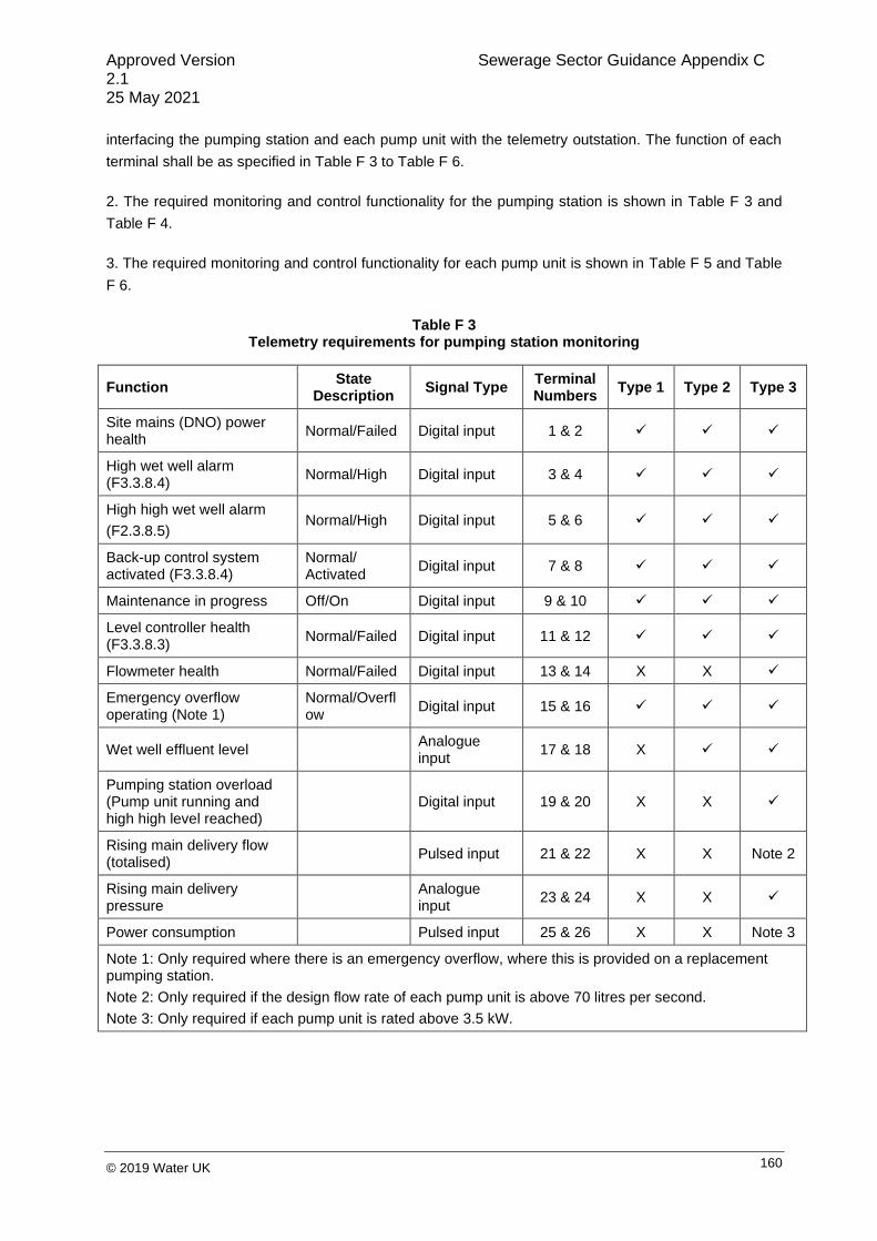
Approved Version Sewerage Sector Guidance Appendix C 2.1 25 May 2021
160 © 2019 Water UK
interfacing the pumping station and each pump unit with the telemetry outstation. The function of each
terminal shall be as specified in Table F 3 to Table F 6.
2. The required monitoring and control functionality for the pumping station is shown in Table F 3 and
Table F 4.
3. The required monitoring and control functionality for each pump unit is shown in Table F 5 and Table
F 6.
Table F 3 Telemetry requirements for pumping station monitoring
Function State
Description Signal Type
Terminal Numbers
Type 1 Type 2 Type 3
Site mains (DNO) power health
Normal/Failed Digital input 1 & 2 ✓ ✓ ✓
High wet well alarm (F3.3.8.4)
Normal/High Digital input 3 & 4 ✓ ✓ ✓
High high wet well alarm
(F2.3.8.5) Normal/High Digital input 5 & 6 ✓ ✓ ✓
Back-up control system activated (F3.3.8.4)
Normal/ Activated
Digital input 7 & 8 ✓ ✓ ✓
Maintenance in progress Off/On Digital input 9 & 10 ✓ ✓ ✓
Level controller health (F3.3.8.3)
Normal/Failed Digital input 11 & 12 ✓ ✓ ✓
Flowmeter health Normal/Failed Digital input 13 & 14 X X ✓
Emergency overflow operating (Note 1)
Normal/Overflow
Digital input 15 & 16 ✓ ✓ ✓
Wet well effluent level Analogue input
17 & 18 X ✓ ✓
Pumping station overload (Pump unit running and high high level reached)
Digital input 19 & 20 X X ✓
Rising main delivery flow (totalised)
Pulsed input 21 & 22 X X Note 2
Rising main delivery pressure
Analogue input
23 & 24 X X ✓
Power consumption Pulsed input 25 & 26 X X Note 3
Note 1: Only required where there is an emergency overflow, where this is provided on a replacement pumping station.
Note 2: Only required if the design flow rate of each pump unit is above 70 litres per second.
Note 3: Only required if each pump unit is rated above 3.5 kW.

Approved Version Sewerage Sector Guidance Appendix C 2.1 25 May 2021
161 © 2019 Water UK
Table F 4 Telemetry requirements for pumping station control
Function State
Description Signal Type
Terminal Numbers
Type 1
Type 2
Type 3
Remote common fault reset (Note 1)
Pulse to reset Pulsed digital output
1 & 2 ✓ ✓ ✓
Remote control select On/off Digital output (on when contacts closed)
3 & 4 X ✓ ✓
Remote pumping station start/stop (when remote operation selected) (Notes 1 and 2)
Enable/ disable
Digital output (on when contacts open)
5 & 6 X ✓ X
Remote pump duty select (Note 1)
Duty standby/ duty assist
Digital output (duty/standby when contacts open)
7 & 8 X ✓ ✓
Note 1: Enabled when remote control selected to On.
Note 2: In Type 3 pumping stations, remote pumping station start/stop is not required as remote pump
units will be provided for each pump (see Table F 6).
Table F 5 Telemetry requirements for the monitoring of each pump unit
Function State
Description Signal Type
Terminal Numbers
Type 1 Type 2 Type 3
Pump unit running Running/ stopped
Digital input 1 & 2 ✓ ✓ ✓
Pump unit tripped Normal/ tripped Digital input 3 & 4 ✓ ✓ ✓
Pump unit available/not available
Available/ unavailable
Digital input 5 & 6 ✓ ✓ ✓
Motor stator temperature Normal/high Digital input 7 & 8 ✓ ✓ ✓
Pump unit vibration caution (Note 1)
Normal/ caution
Digital input 9 & 10 X X Note 2
Pump unit vibration high (Note 1)
Normal/high Digital input 11 & 12 X X Note 2
Pump unit seal failure (moisture in pump)
Normal/failed Digital input 13 & 14 X X Note 3
Pump unit lower bearing temperature
Normal/high Digital input 15 & 16 X X Note 2
Pump unit load (for partial pump blockage)
Normal/ underload
Digital input 17 & 18 Note 4 Note 4 ✓
Note 1: Zero vibration is defined as the level of vibration when the pumping station is newly commissioned and in good condition.

Approved Version Sewerage Sector Guidance Appendix C 2.1 25 May 2021
162 © 2019 Water UK
Note 2: Only required if each pump unit is rated at or above 22 kW.
Note 3: Only required if each pump unit is rated at or above 7.5 kW.
Note 4: Will normally be required in all cases where the pump unit is in a hazardous zone, in accordance with the Dangerous Substances and Explosive Atmospheres Regulations 2002.
Table F 6 Telemetry requirements for the control of each pump unit
Function State
Description Signal Type
Terminal Numbers
Type 1 Type 2 Type 3
Remote pump unit control Start/stop
Digital output (pump unit on when contacts open)
1 & 2 X X ✓
Note 1: Enabled when remote control selected to On.
4. Digital inputs (i.e., providing a signal to the telemetry outstation), shall be volt-free contacts
configured with the closed contact for the healthy state. If the contact is provided by a relay, then the
relay shall be energised when the equipment is healthy.
5. Analogue inputs (i.e., providing a signal to the telemetry outstation) shall be a 4-20 mA current loop
with a maximum loop impedance from the telemetry outstation of 250 Ohms. They shall be calibrated
such that 4 mA represents a zero measurement and 20 mA represents a full-scale measurement. A
current of less than 4 mA represents a fault condition.
6. Pulsed inputs (i.e., providing a signal to the telemetry outstation) shall be via normally open volt-free
contacts, providing a closed contact each time the total is incremented by one unit. The duration and
frequency of the pulse shall be compatible with the particular telemetry outstation used; the instrument
generating the pulses shall be configured to achieve this. If the instrument does not have volt-free
outputs then an interposing relay shall be used.
7. For digital outputs, the control system shall respond to a pair of volt-free contacts in the telemetry
outstation rated at no less than 24 volts and 1 amp. Pulsed digital output, contacts shall be closed for at
least ten seconds.
F3.3.10 Ultrasonic level controller (ULC) specification
F3.3.10.1 Normal operation
1. The ULC shall be configured to sequentially rotate the pump unit duty/standby status each time all
pump units are stopped to ensure equal pump unit usage.
2. The ULC shall be configured to initiate a wet well cleaning "snore" cycle once a day (i.e., allow the
duty pump unit to "over-run" down to L1 during periods of high/peak flows into the wet well). L1 shall be
chosen to be as low as possible without affecting the safe/effective operation of the pump units; the

Approved Version Sewerage Sector Guidance Appendix C 2.1 25 May 2021
163 © 2019 Water UK
pump unit manufacturer shall be consulted to this end. Pump unit underload protection must not be
overridden by this cycle.
3. The ULC shall be configured so that the wet well level readings are displayed (and/or, if required,
transmitted via telemetry) in metres.
4. The ULC shall be configured so that the "zero level" reading in the wet well corresponds to L1, i.e.,
the level below which the pump units cannot pump anymore.
F3.3.10.2 Features
1. The ULC shall incorporate a number of relays (minimum of five) to operate the pump units and
alarms according to the required control philosophy.
2. The ULC shall incorporate a 4-20 mA output (typically used for remote wet well level monitoring via
telemetry).
3. The ULC shall incorporate a number of digital inputs (see F3.3.9).
4. The ULC shall incorporate a real-time clock with facility to automatically correct for GMT/BST.
5. The ULC shall incorporate a clear visual display of settings/parameters and conditions using
standard engineering units. The display shall be visible during times of low light (e.g., by means of a
back light).
6. The ULC shall be capable of communication with the upstream telemetry outstation via either a hard-
wired connection or serial data communications.
7. The ULC shall be suitable for fascia or panel mounting.
8. The ULC shall be suitable for operation from a 24 V dc/110 V ac control circuit supply.
9. The ULC shall be suitable for operating pump units installed in a wet well classified as a hazardous
area.
F3.3.10.3 Functionality
1. The ULC shall be capable of measuring levels from 0.3 to 15 m with an accuracy of 0.25% (based on
the distance between the transducer head and the liquid level).
2. The ULC shall be capable of accurately logging the following parameters for each pump unit:
a) total volume pumped;
b) pump unit efficiency;
c) number of hours run (normal operation and run-on hours); and
d) number of starts.

Approved Version Sewerage Sector Guidance Appendix C 2.1 25 May 2021
164 © 2019 Water UK
3. All operator-programmed settings/control parameters shall be stored in non-volatile memory to
ensure that settings/control parameters are not affected by power interruption.
4. The ULC shall allow restricted access to parameter settings (e.g., by means of password protection)
and have the ability to secure all programming from inadvertent alteration.
5. Setting/configuration of parameters shall not require the use of a laptop computer nor shall it require
the operator to enter or lean into the wet well to configure its parameters.
6. The ULC shall be capable of the following basic pump functions:
a) fixing the pump unit duty/standby status (fixed pump function);
b) sequentially rotating the pump unit duty/standby status (each time all pump units are stopped)
to ensure equal pump unit usage (alternate pump function); and
c) allowing one pump unit to be used in preference to the other (pump service ratio function).
7. The ULC shall be capable of allowing the pump units to "run-on" to a level below the normal stop
level for a specified time for the wet well cleaning/snore cycle (see F3.3.10.1). The pump unit "run-on"
interval and duration shall be adjustable to allow optimisation of the cleaning cycle without causing
pump unit maloperation or damage.
8. The ULC shall be capable of switching the pump units on for a variable time period after long periods
of inactivity (pump exercising) to verify pump unit operation and to prevent blockage and drying out of
seals (provided that a minimum suction head is available).
9. The ULC shall be capable of randomly varying the pump unit start and stop points within a selectable
range to minimise the build up of grease and other material in the wet well (wall cling reduction).
10. The ULC shall be capable of varying pumping set points to take advantage of low electricity rates
(pump energy cost reduction), i.e., the controller shall pump down the wet well to a low level when
power is cheapest and maintain higher levels when power rates are at a premium.
11. The ULC shall be capable of transmitting a “Loss of Pump Efficiency” alarm.
12. The ULC shall be capable a transmitting a signal to a flow totaliser to enable the pumped volume to
be recorded remotely from the controller.
F3.3.11 Functional units – Form 4 assemblies
F3.3.11.1 General
1. The electrical assembly shall, as a minimum, incorporate the following functional units:
a) an incomer compartment;
b) a "Pump Unit No. 1" motor starter compartment;
c) a "Pump Unit No. 2" motor starter compartment;

Approved Version Sewerage Sector Guidance Appendix C 2.1 25 May 2021
165 © 2019 Water UK
d) a common control compartment; and
e) a cable marshalling compartment or cable-way.
2. A typical panel layout is shown in Table F 2.
3. The form of separation of the electrical assembly shall be Form 4a or 4b. Separation of functional
units shall be achieved by partitions or barriers and not via the integral housing of a device.
F3.3.11.2 Incomer compartment
1. The electrical assembly shall be supplied from one incoming power supply from the DNO with the
facility for a mobile generator supply.
2. The incomer compartment shall, as a minimum, accommodate the following equipment and facilities:
a) two 4-pole (3-phase and switched neutral) fuse switches with suitably-rated HRC fuses,
mechanically interlocked and assembled to form a switch for the mains and mobile generator
supplies. The switch shall be linked to a switch to disconnect and connect the earthing
conductor (see F3.4.6.1.5) for the appropriate source at substantially the same time as the
related live conductors and shall be labelled "Mains/Off/Generator";
b) a phase failure, phase reversal and low voltage protection relay to provide a "Mains Failure"
telemetry signal. The phase failure detection relay shall be connected downstream of the
"Mains/Off/Generator" switch;
c) a set of fuses and a neutral link for the phase failure relay and voltmeter (see F3.3.11.2.3
below); and
d) power monitoring facilities if the rating of each pump unit is above 3.5 kW.
3. The following equipment shall, as a minimum, be mounted on the door of the incomer compartment:
a) the common operating handle for the two 4-pole (3-phase and switched neutral) fuse
switches. This shall be door interlocked and padlockable in the "Off" position;
b) a voltmeter, scaled 0-500 V, and 7-position selector switch;
c) an ammeter; and
d) a fuse-fed, single phase and neutral, distribution board, complying with BS EN 61439-3, with
integral isolator and hinged cover. All MCBs, RCDs and RCBOs incorporated within the
distribution board shall comply with BS EN 60898, BS EN 61008 and BS EN 61009,
respectively, and be padlockable in the "Off" position.
e) kiosk anti-condensation heater;
f) kiosk lighting;
g) kiosk socket outlet supplies;
h) telemetry outstation; and
i) spare.
5. All five circuits shall be wired to outgoing terminals.

Approved Version Sewerage Sector Guidance Appendix C 2.1 25 May 2021
166 © 2019 Water UK
F3.3.11.3 Control circuit supplies
1. Control circuit supplies shall comply with the requirements of BS EN 60204-1. The control circuit
supply voltage shall be 110 V ac or 24 V dc.
2. The common control and motor starter functional units shall each be provided with a dedicated
control circuit transformer (CCT).
3. The common control and motor starter functional units shall each be provided with a means of
switching, isolation and short-circuit protection for the incoming control circuit supplies. Control circuit
supplies shall be energised when the associated fuse switch is in the "On" or "Test" position.
4. The primary and secondary windings of all CCTs shall be protected by fuses or double pole MCBs.
Removable neutral links shall be provided if protection is afforded by fuses.
4. With respect to item d) above, the distribution board shall comprise a minimum of five ways, which
shall be suitably-rated and labelled for the following duties:

Approved Version Sewerage Sector Guidance Appendix C 2.1 25 May 2021
167 © 2019 Water UK
Figure F 2 Standard flush mount davit socket

Approved Version Sewerage Sector Guidance Appendix C 2.1 25 May 2021
168 © 2019 Water UK

Approved Version Sewerage Sector Guidance Appendix C 2.1 25 May 2021
169 © 2019 Water UK
5. CCTs shall be double-wound and comply with the relevant parts of BS EN 61558.
6. CCTs shall have one side of their secondary windings earthed. CCTs shall incorporate a separate
earth screen for each secondary voltage, with each screen having a connection point on the
transformer terminal block. A common protective conductor shall be used for earthing the screen
terminals. Neutrals or negatives of control circuit supplies shall be connected to earth at one point only.
7. CCTs shall be wired as follows:
a) P1 – 400 V L1;
b) P2 – 400 V L2;
c) S1 – 110/24 V neutral; and
d) S2 – 110/24 V live.
8. The power rating of each CCT shall be equal to the maximum "hold-in" VA rating of all
simultaneously-energised control equipment plus the "pull-in" VA rating of the largest device, or the
total of all devices that may operate simultaneously, whichever is the greater.
F3.3.11.4 Motor starter compartments
1. Each motor starter compartment shall, as a minimum, accommodate the following equipment:
a) a triple-pole fuse switch with three suitably-rated HRC fuses and auxiliary switching of all live
and neutral control circuits (complete with test position);
b) motor contactor(s);
c) a 3-phase thermal overload relay with single phasing protection;
d) a control circuit transformer, control circuit fuses and links;
e) additional motor protection systems (see F3.3.11.4.3 below); and
f) all necessary relays and timers (including proprietary brown-out and restart relays and
timers).
2. With respect to F3.3.11.4.1 a) above, when the fuse switch is in the "Test" position, only control
circuit voltages shall be present within the compartment.
3. With respect to F3.3.11.4.1 e) above, motor starters shall incorporate the following additional motor
protection systems:
a) motor over-temperature protection;
b) pump unit mechanical seal failure protection (if the pump unit is rated at or above 7.5 kW);
c) motor underload protection; and
d) motor earth fault protection (if the total earth loop impedance of the motor circuit results in a
fault clearance time of greater than 0.4 seconds).
4. All motor protection systems shall be of the electrically-latched and manually-reset type.

Approved Version Sewerage Sector Guidance Appendix C 2.1 25 May 2021
170 © 2019 Water UK
5. The following equipment shall, as a minimum, be mounted on the door of each motor starter
compartment:
a) the operating handle for the fuse switch. This shall be door interlocked and padlockable in the
"Off" position;
b) a “Hand/Off/Auto” selector switch;
c) a “Common Fault” Reset push-button;
d) a "Pump Unit Start" push-button;
e) a "Pump Unit Stop" push-button;
f) a "Pump Unit Tripped" lamp;
g) a "Pump Unit Running" lamp;
h) an “Auto-available” lamp;
i) individual fault lamps;
j) an ammeter; and
k) an “Hours Run” meter.
6. All motor starters shall provide Type 2 Co-ordination to BS EN 60947-4.
7. The proprietary brown-out timer shall instigate an automatic reset of the protection circuits upon
reinstatement of control circuit supplies or on any disturbance of the control circuit supplies likely to
result in the maloperation of the control circuits or relays.
8. If the wet well is classified as a hazardous area, the motor starters shall incorporate all necessary
hazardous area facilities (e.g., motor over-temperature protection systems, intrinsically-safe barriers,
etc.) in compliance with the requirements of the relevant Standard and Certificate of Conformity.
F3.3.11.5 Common control compartment
1. The common control compartment (CCC) shall, as a minimum, accommodate the following common
control equipment (CCE):
a) a double pole (single phase and neutral) fuse switch with auxiliary switching of all live and
neutral control circuits;
b) a control circuit transformer;
c) separate fuses and links for the ultrasonic level control system, control circuits and back-up
float switch level control system;
d) an ultrasonic level controller (or equivalent) to enable start, stop, control and sequencing of
the pump units to control the sewage level in the wet well;
e) a back-up float switch level control system relay and timer to operate a given pump unit for a
set period (using a high-level float switch in the wet well) in the event of failure of the
ultrasonic level control system (see F3.3.8.4); and
f) a separate high, high-level float switch relay for a high high-level alarm (operated from a
separate float switch in the wet well).

Approved Version Sewerage Sector Guidance Appendix C 2.1 25 May 2021
171 © 2019 Water UK
2. With respect to F3.3.11.5.1 e) and F3.3.11.5.1 f) above, if the wet well is classified as a hazardous
area, all connections to float switches shall be via intrinsically-safe isolators/barriers.
3. In addition to the HMI (human machine interface) for the ultrasonic level controller (or equivalent), the
following equipment shall, as a minimum, be mounted on the door of the common control compartment:
a) the operating handle for the fuse switch. This shall be door interlocked and padlockable in the
"Off" position;
b) a "Back-up Float Switch Level Control System Activated" indicator lamp; and
c) a Reset button for item b) above (see F3.3.8.4.7).
4. The design and construction of the CCC shall enable safe inspection, testing, calibration and
diagnostic activities to be carried out with the CCE energised and accessible. Safe testing shall be
afforded by the use of extra-low voltage systems and segregation of circuits employing different
voltages. Additional localised shrouding of circuits above extra-low voltage shall be provided to IP2X
minimum.
5. Every circuit within the CCC shall be provided with a clearly-identifiable means of switching and
isolation for individual items or groups of equipment, as required, for the correct operation of the
pumping station. Suitably-rated overcurrent protection devices shall be provided at all points necessary
for the protection and isolation of every circuit and to minimise disruption to the overall system on
failure of a component part of that system.
6. Apparatus and systems associated with hazardous area installations, as defined in BS EN 60079-10-
1, shall be segregated from other CCE in an approved manner, in compliance with the requirements of
the relevant Standard and Certificate of Conformity.
7. Terminals for connecting an externally-mounted telemetry outstation to the electrical assembly’s I/O
shall form part of the CCE and be labelled "Telemetry Terminals".
F3.3.11.6 Cable marshalling compartment or cable-way
1. A cable marshalling compartment or cable-way shall be provided for marshalling outgoing and bus
wiring cables. It shall be configured to provide adequate access to all cables entering or leaving
functional units.
2. Incomer, motor starter, CCE and telemetry terminals shall not be located within this compartment.
3. This compartment shall incorporate the common, solid earth bar or stud arrangement (see Section
F3.3.4.3).

Approved Version Sewerage Sector Guidance Appendix C 2.1 25 May 2021
172 © 2019 Water UK
F3.3.12 Functional units – Form 2 assemblies
F3.3.12.1 General
1. Where a Form 2 electrical assembly is provided, the incomer equipment shall not be incorporated
into the assembly but shall be installed separately within the kiosk.
F3.3.12.2 Incomer equipment
1. The electrical assembly shall, as a minimum, incorporate the following functional units:
a) control circuit supplies;
b) a "Pump Unit No. 1" motor starter;
c) a "Pump Unit No. 2" motor starter; and
d) a common control compartment.
2. The form of separation of the electrical assembly shall be Form 2a or 2b.
3. The incoming supply cable terminals shall be segregated and shrouded from other terminals and
shall be wired directly onto the main incoming switching and isolation device.
4. Components associated with the same starters or control functionality shall be grouped together in a
logical order. The components of different starters shall be segregated by additional space.
5. The common control equipment shall be housed in a separate compartment to all other functional
units (see F3.3.12.6).
F3.3.12.3 Incomer
1. The electrical assembly shall be supplied from one mains incoming power supply from the DNO.
2. The incomer shall, as a minimum, incorporate the following equipment and facilities:
a) a 4-pole (3-phase and switched neutral) fuse switch with three suitably-rated HRC fuses. The
switch shall be labelled "On/Off/Test";
b) a phase failure, phase reversal and low voltage protection relay to provide a "Mains Failure"
telemetry signal. The phase failure detection relay shall be connected downstream of the
"On/Off/Test" switch; and
c) a set of fuses and a neutral link for the phase failure relay and voltmeter (see clause
F3.3.12.3.3 below).
3. The following equipment shall, as a minimum, be mounted on the door of the electrical assembly
adjacent to the incomer:
a) the common operating handle for the triple pole and switched neutral fuse switch. This shall
be door interlocked and padlockable in the "Off" position;
b) a voltmeter, scaled 0-500 V, and seven-position selector switch;

Approved Version Sewerage Sector Guidance Appendix C 2.1 25 May 2021
173 © 2019 Water UK
c) an ammeter; and
d) a fuse-fed, single phase and neutral, distribution board, complying with BS EN 61439-3, with
integral isolator and hinged cover. All MCBs, RCDs and RCBOs incorporated within the
distribution board shall comply with BS EN 60898, BS EN 61008 and BS EN 61009,
respectively, and be padlockable in the "Off" position.
4. With respect to F3.3.12.2.3 d) above, the distribution board shall comprise a minimum of five ways,
which shall be suitably-rated and labelled for the following duties:
a) kiosk anti-condensation heater;
b) kiosk lighting;
c) kiosk socket outlet supplies;
d) telemetry outstation; and
e) spare.
5. All five circuits shall be wired to outgoing terminals.
F3.3.12.4 Control circuit supplies
1. Control circuit supplies shall be housed within the electrical assembly adjacent to the incomer.
2. Control circuit supplies shall comply with the requirements of BS EN 60204-1. The control circuit
supply voltage shall be 110 V ac or 24 V dc.
3. The primary and secondary windings of the CCTs shall be protected by fuses or double pole MCBs.
Removable neutral links shall be provided if protection is afforded by fuses.
4. CCTs shall be double-wound and comply with the relevant parts of BS EN 61558.
5. CCTs shall have one side of their secondary windings earthed. CCTs shall incorporate a separate
earth screen for each secondary voltage, with each screen having a connection point on the
transformer terminal block. A common protective conductor shall be used for earthing the screen
terminals. Neutrals or negatives of control circuit supplies shall be connected to earth at one point only.
6. CCTs shall be wired as follows:
a) P1 – 400 V L1;
b) P2 – 400 V L2;
c) S1 – 110/24 V neutral; and
d) S2 – 110/24 V live.
7. The power rating of each CCT shall be equal to the maximum "hold-in" VA rating of all
simultaneously-energised control equipment plus the "pull-in" VA rating of the largest device, or the
total of all devices that may operate simultaneously, whichever is the greater.

Approved Version Sewerage Sector Guidance Appendix C 2.1 25 May 2021
174 © 2019 Water UK
F3.3.12.5 Motor starters
1. The electrical assembly shall be provided with two motor starters. Each motor starter shall, as a
minimum, incorporate the following equipment:
a) suitable isolating, overload and short circuit protection device(s);
b) motor contactor(s);
c) a 3-phase thermal overload relay with single phasing protection;
d) control circuit fuses and links;
e) additional motor protection systems (see F3.3.12.5.2 below); and
f) all necessary relays and timers.
2. With respect to F3.3.12.5.1 e) above, motor starters may incorporate the following additional motor
protection systems:
a) motor over-temperature protection;
b) pump unit mechanical seal failure protection (if the pump unit is rated at or above 7.5 kW);
c) motor underload protection; and
d) motor earth fault protection (if the total earth loop impedance of the motor circuit results in a
fault clearance time of greater than 0.4 seconds).
3. All motor protection systems shall be of the electrically-latched and manually-reset type.
4. The following equipment shall, as a minimum, be mounted on the door of the electrical assembly
adjacent to each motor starter:
a) a “Hand/Off/Auto” selector switch;
b) a “Common Fault Reset” push-button switch (this may be common to both motor starters);
c) a "Pump Unit Start" push-button switch;
d) a "Pump Unit Stop" push-button switch;
e) a "Pump Unit Tripped" lamp;
f) a "Pump Unit Running" lamp;
g) an "Auto-available" lamp;
h) individual fault lamps; and
i) an “Hours Run” meter.
5. All motor starters shall provide Type 2 Co-ordination to BS EN 60947-4.
6. The proprietary brown-out timer shall instigate an automatic reset of the protection circuits upon
reinstatement of control circuit supplies, or on any disturbance of the control circuit supplies likely to
result in the maloperation of the control circuits or relays.
7. If the wet well is classified as a hazardous area, the motor starters shall incorporate all necessary
hazardous area facilities (e.g., motor over-temperature protection systems, intrinsically-safe barriers,
etc.) in compliance with the requirements of the relevant Standard and Certificate of Conformity.

Approved Version Sewerage Sector Guidance Appendix C 2.1 25 May 2021
175 © 2019 Water UK
F3.3.12.6 Common control section
1. The common control section (CCS) shall, as a minimum, accommodate the following common
control equipment (CCE):
a) suitable isolating, overload and short circuit protection devices;
b) separate fuses and links for the ultrasonic level control system, control circuits and back-up
float switch level control system;
c) an ultrasonic level controller (or equivalent) to enable start, stop, control and sequencing of
the pump units to control the sewage level in the wet well;
d) a back-up float switch level control system relay and timer to operate a given pump unit for a
set period (using a high-level float switch in the wet well) in the event of failure of the
ultrasonic level control system;
e) a separate high, high-level float switch relay for a high high-level alarm (operated from a
separate float switch in the wet well); and
f) all necessary relays and timers (including proprietary brown-out and restart relays and
timers).
2. With respect to F3.3.12.6.1 d) and e) above, if the wet well is classified as a hazardous area, all
connections to float switches shall be via intrinsically-safe connections.
3. In addition to the HMI for the ultrasonic level controller (or equivalent), the following equipment shall,
as a minimum, be mounted on the door of the common control section:
a) a "Back-up Float Switch Level Control System Activated" indicator lamp; and
b) a “Reset” button for item a) above.
4. The design and construction of the CCS shall enable safe inspection, testing, calibration and
diagnostic activities to be carried out with the CCE energised and accessible. Safe testing shall be
afforded by the use of extra-low voltage systems and segregation of circuits employing different
voltages. Additional localised shrouding of circuits above extra-low voltage shall be provided to IP4X
minimum.
5. Every circuit within the CCS shall be provided with a clearly-identifiable means of switching and
isolation for individual items or groups of equipment, as required, for the correct operation of the
pumping station. Suitably-rated overcurrent protection devices shall be provided at all points necessary
for the protection and isolation of every circuit and to minimise disruption to the overall system on
failure of a component part of that system.
6. Apparatus and systems associated with hazardous area installations, as defined in BS EN 60079-10,
shall be segregated from other CCE in an approved manner in compliance with the requirements of the
relevant Standard and Certificate of Conformity.
7. Terminals for connecting an externally-mounted telemetry outstation to the electrical assembly’s I/O
shall form part of the CCE and be labelled "Telemetry Terminals".

Approved Version Sewerage Sector Guidance Appendix C 2.1 25 May 2021
176 © 2019 Water UK
F3.4 Pumping Station Electrical Installation
F3.4.1 Electrical components and equipment (excluding the electrical assembly and cables)
F3.4.1.1 General
1. All components and equipment shall be suitable for their intended duty, particularly with respect to
the following:
a) the electrical supply and load requirements;
b) the degree of ingress protection (IP rating);
c) the environmental conditions (particularly corrosion resistance); and
d) the mechanical properties (especially impact strength).
F3.4.1.2 Socket outlet
1. A splashproof, 16 A, 230 V, IP54 (minimum) socket outlet, complying with BS EN 60309-2, shall be
provided inside the kiosk. This shall be provided with 30 mA RCD protection.
F3.4.1.3 Luminaires
1. A number of suitably-rated, IP56, fluorescent luminaires shall be securely mounted inside the kiosk
at roof level to illuminate the DNO supply section, electrical assembly and all associated equipment.
2. The luminaires shall be provided with a splashproof "On/Off" switch, complying with BS EN 60669-1,
mounted inside the kiosk, adjacent to a door.
F3.4.1.4 Anti-condensation heaters
1. The kiosk shall be equipped with a number of suitably-rated, tubular, anti-condensation heaters.
Heaters shall be controlled by tamperproof thermostats, initially set at 5oC.
F3.4.1.5 Junction boxes
1. Junction boxes shall be designed for bottom cable entry.
2. Junction boxes shall be sized so that there is adequate space between the point of cable entry and
the terminals, such that cable cores may be spread, loomed, identified, terminated and subsequently
removed for testing, without experiencing excessive bending or stress.
3. Junction boxes shall be provided with an adequate means of earthing.
4. Terminals shall be clipped to rails fixed to the back of the junction box or supported off brackets
integral with the junction box.
5. When a junction box is open, the degree of ingress protection to any live part, or to any part that
could be energised at above low voltage during any test procedure, shall be a minimum of IP2X.

Approved Version Sewerage Sector Guidance Appendix C 2.1 25 May 2021
177 © 2019 Water UK
6. Junction box lids or covers shall be secured closed by captive, threaded fasteners.
F3.4.2 Installation of components and equipment
1. All equipment shall be securely mounted using proprietary fixtures and fittings.
2. Equipment terminals and covers shall be readily and safely accessible after installation.
3. The method of equipment installation shall not affect the IP rating of the equipment.
4. Unless otherwise agreed with the sewerage company, cable access to all electrical enclosures shall
be bottom entry.
F3.4.3 Cables
1. All cables shall be manufactured, tested and certified in accordance with a procedure approved by
the British Approvals Service for Electric Cables (BASEC) and shall comply with the latest relevant
British or harmonised European Standards.
2. Cable selection and sizing shall comply with the requirements of BS 7671 and the recommendations
of IET Guidance Note No. 1: Selection & Erection, with particular reference to Appendix H.
3. Cables shall have copper conductors complying with BS EN 13602. Cores of cross-sectional area
greater than 1.5 mm2 shall be stranded or flexible.
4. If neutral conductors are provided, they shall be of the same cross-sectional area as the associated
line conductor.
5. The types/ratings and sizes of cables selected for a given application shall comply with Table F 7.
Table F 7 Types/Ratings and Sizes of Cables
Application Type/Rating Minimum Conductor CSA
Electricity distributor’s 3-phase and neutral cable tails
BS 5467 rated at 600/1000 V According to duty
Installation earth cable BS 6231 rated at 600/1000 V 16 mm2
Kiosk lighting, heating and power cables1
BS 6004 (Table 1) rated at 450/750 V
1.0 mm2 (lighting) 2.5 mm2 (heating and power)
Pump unit cables See F3.4.5.4 2.5 mm2
Ultrasonic level sensor cable As supplied by manufacturer As supplied by manufacturer
Float switch cables As supplied by manufacturer As supplied by manufacturer
Electrical assembly to telemetry outstation
PAS 5308-1/BS EN 50288-7 0.5 mm2

Approved Version Sewerage Sector Guidance Appendix C 2.1 25 May 2021
178 © 2019 Water UK
Note 1: The colour of the insulation on live and neutral cables shall be brown and blue, respectively.
F3.4.4 Installation of cables
1. Cable installation shall comply with the requirements of BS 7671 and the recommendations of IET
Guidance Note No. 1: Selection &Erection (8th edition) with particular reference to Appendix I.
2. Cables and cable support systems shall not be fixed to pump unit guide rails.
3. Joints shall not be permitted in individual power and control cables, except at junction boxes.
4. Cables that may be subject to accidental mechanical damage shall be suitably protected. The degree
of mechanical protection offered to cables (e.g., installation in PVC ducting, metal conduit, etc.) shall be
appropriate to the likelihood and consequences (i.e., risk) of cable damage.
5. Ducts shall be provided for installation of the following:
a) the DNO’s incoming power cable. One duct shall be provided, sized in accordance with the
DNO’s specification (e.g., colour, size, etc.) and routed between the point of supply and the
kiosk plinth, in accordance with the DNO requirements;
b) the installation earth cable. One duct shall be provided, 50 mm in diameter and routed
between the point of supply and the kiosk plinth;
c) the pump unit cables. Two ducts shall be provided, 150 mm in diameter and routed between
the wet well and kiosk plinth, see F3.4.5.4;
d) the ultrasonic level sensor and float switch cables. One duct shall be provided, 100 mm in
diameter and routed between the wet well and the kiosk plinth;
e) where the signal is to be transmitted through the public telephone network, one duct shall be
provided for the telemetry cable, sized according to the telephone company’s requirements,
and routed between the kiosk plinth and the point of connection to the public telephone
network; and
f) where the telemetry signal is to be transmitted by other means, the sewerage company shall
be consulted regarding their requirements.
6. Ducts shall consist of rigid black or grey PVC-U pipe, complying with BS EN 1401-1 and BS 4660.
7. Changes in direction of ducts shall be achieved using long radius bends. Ducts shall have self-
aligning, watertight joints and a smooth internal bore. All accessories shall be proprietary and made
from the same material as the duct.
8. The ducts for the pump unit cables shall enter the wet well near to its top so that the pump unit
cables can be easily reached from the top of the wet well.

Approved Version Sewerage Sector Guidance Appendix C 2.1 25 May 2021
179 © 2019 Water UK
9. Ducts shall terminate approximately 75 mm proud of the surface of the plinth.
10. Depth of cover in soft ground shall be a minimum of 500 mm above the crown of the duct.
11. On completion, all ducts shall have a swab drawn through to clear them of obstructions.
12. Ducts shall be left with an excess 1 m length of 8 mm diameter nylon drawcord in place, anchored
at each end.
13. After installation of cables, all ducts shall be sealed with a proprietary (fire-retardant and gas and
watertight) sealing system. Cable transit block style sealing systems or polyurethane foam shall not be
used.
14. Conduit shall be provided for installation of the cables associated with the kiosk lighting and heating
systems and/or socket outlets.
15. Conduit shall be manufactured from 20 mm diameter, high-impact resistance, heavy-gauge PVC-U
and comply with BS EN 61386-1 and BS EN 61386-21. The outside diameters of conduits and the
dimensions of threads for conduits and fittings shall comply with BS EN 60423. All fittings shall be
glued.
F3.4.5 Glanding, identification and termination of cables
F3.4.5.1 Glanding
1. The construction and performance of cable glands shall comply with BS EN 62444.
2. Cable glands shall be suitable for the type of cable being installed and its intended operating
environment. Cable gland selection shall, as a minimum, consider the following performance
requirements:
a) mechanical properties;
b) electrical properties; and
c) resistance to external influences. The minimum degree of ingress protection shall be IP66 in
accordance with BS EN 60529.
3. All glands selected for use on steel wire armoured (SWA) cables shall incorporate sealing on the
outer sheath.
4. Where a cable is glanded through a painted or otherwise coated metallic surface, provision shall be
made to ensure earth continuity between the gland and the enclosure.
F3.4.5.2 Identification
1. Cable cores shall be identified at both ends by interlocking ferrules or another approved system.
Cables shall be uniquely identified.
Approved Version Sewerage Sector Guidance Appendix C 2.1 25 May 2021
180 © 2019 Water UK
2. Where provided, identification labels shall be legible, durable and securely affixed to the cable
sheath by means of buckle-type straps, and shall carry the cable reference in PVC channel strip. The
reference character sizes shall be not less than 3 mm high. Cables shall be uniquely identified.
F3.4.5.3 Termination
1. Termination of cables shall comply with F3.3.5.4.
F3.4.5.4 Connection of pump unit cables
1. If the pumping station is located in a secure compound, each pair of cables shall be connected in a
separate weatherproof junction box, located adjacent to the top of the wet well.
2. If the pumping station is not located in a secure compound, each pump unit cable shall be directly
cabled to the electrical assembly via the duct provided (i.e., without any intermediate joints). If the wet
well is designated as a hazardous area, the kiosk shall be provided with facilities to prevent the ingress
of explosive or corrosive gases into the kiosk (e.g., block and bleed system, etc.) in the event that the
normal duct sealing arrangements are compromised.
F3.4.6 Earthing and bonding
F3.4.6.1 General
1. All earthing and equipotential bonding shall be performed in accordance with:
a) BS 7671, with particular reference to the recommendations of IET Guidance Note 5:
Protection Against Electric Shock and IET Guidance Note 8: Earthing & Bonding;
b) BS 7430; and
c) the Electricity Safety, Quality and Continuity Regulations 2002.
2. Typical earthing arrangements are shown in Figure F 3.
3. Prior to design of the earthing system, the type of earthing and the external earth fault loop
impedance shall be obtained from the DNO. The documentary evidence of this information shall be
provided on request.
4. The earthing system shall be compatible with any existing DNO earthing system.
5. A changeover contactor shall be provided to disconnect the pumping station from the DNO's main
earth terminal (MET) and connect it to the earth electrode (see F3.3.6.2), in the event that a mobile
generator is connected to the pumping station. This shall be linked to generator changeover switch (see
F3.3.11.2) so that the earthing conductor is disconnected and connected for the appropriate source, at
substantially the same time as the related live conductors.
F3.4.6.2 Earth electrode
F3.4.6.2.1 General

Approved Version Sewerage Sector Guidance Appendix C 2.1 25 May 2021
181 © 2019 Water UK
1. If the pumping station has the provision for the connection of a mobile generator (Type 3 pumping
stations), then an earth electrode shall be provided.
2. The earth electrode shall be connected to a stud terminal provided in the kiosk for connection of the
mobile generator star point to the earth electrode.
F3.4.6.2.2 Earth electrode
1. The earth electrode shall comprise a number of interconnected earth rod assemblies, driven into the
ground external to the kiosk.
2. Each earth rod assembly shall comprise a number of copper-clad, high-tensile steel rods. Rods shall
be at least 16.0 mm (nominal) in diameter with hardened steel tips and driving caps. Individual rods
shall be no more than 1.2 m long. The copper cladding shall be molecularly bonded to the steel and be
not less than 0.25 mm thick.
3. Connections between individual rods shall be by screwed joints. A corrosion-inhibiting paste shall be
applied to all threads before assembly.
4. A single earth rod assembly shall be not more than 6 m long and the separation between adjacent
earth rod assemblies shall be not less than 1.25 times the length of the longest earth rod assembly.
5. The earth rod assemblies shall be interconnected using earthing conductors, consisting of bare
copper tape, sized according to the anticipated fault current. The final earthing conductor (which will
connect the earth electrode to the main earth terminal (MET)) shall be a copper tape or stranded
conductor and shall be sheathed in green/yellow PVC insulation.
6. Inspection pits shall be installed at the point of connection of every earthing conductor to an earth rod
assembly. Inspection pits shall be mounted flush with the finished ground level and be fitted with a
prominently-labelled, removable lid. If the pit is installed in an area of hardstanding, the pit and lid shall
be manufactured from concrete. In each inspection pit, a label, stating "Safety Electrical Earth – Do Not
Remove", shall be permanently attached to the point of connection between the earth rod assembly
and earthing conductor.
7. The earth electrode shall provide a maximum effective earth resistance of 10 Ohms.
F3.4.6.3 Bonding
F3.4.6.3.1 General
1. PVC-coated copper tape or cable shall be used for bonding connections (i.e., aluminium or copper-
clad aluminium conductors shall not be used).
2. Metal tabs worded "Safety Electrical Earth – Do Not Remove" shall be attached to all bonding
connections.
F3.4.6.3.2 Main equipotential bonding

Approved Version Sewerage Sector Guidance Appendix C 2.1 25 May 2021
182 © 2019 Water UK
1. All extraneous conductive parts of the pumping station shall be connected to the main earthing
terminal (MET).
2. The bonding conductor shall be connected to the various connection points in the kiosk, valve
chamber and wet well, as indicated in Figure F3. The bonding conductor shall be continuous and not
cut at each connection.
F3.4.6.3.3 Supplementary equipotential bonding
1. Any extraneous conductive parts, i.e., any metalwork not forming part of the pumping station
(electrical) but which itself may have some connection with the mass of earth and which is in such a
position that a person could make simultaneous contact between it and an exposed conductive part of
the electrical installation, shall be bonded to the nearest exposed conductive part, unless it can be
shown to be in otherwise good contact with the earthing system.
2. Supplementary bonding of a permanent and reliable nature shall be carried out to extraneous
conductive parts in a manner that takes due consideration of subsequent maintenance activities.
3. If the use of pipework or equipment with specialised, fully-protective, non-conducting surface
preparations cannot guarantee earth continuity (notably across flanged joints), then supplementary
earth bonding conductors, or purpose-designed hardware ensuring continuity, shall be used.
4. Metallic cable and wiring support systems shall be bonded to all non-electrical services.
F3.4.6.4 Joints and connections
F3.4.6.4.1 Joints
1. Joints in cables and tapes shall not be permitted.
F3.4.6.4.2 Connections
1. Connections shall be made:
a) to main earthing terminals by phosphor bronze set screws and nuts; and
b) to earth rods by bronze, gunmetal, or copper clamps, with phosphor bronze bolts.

Approved Version Sewerage Sector Guidance Appendix C 2.1 25 May 2021
183 © 2019 Water UK
Figure F 3 Typical earthing arrangements
Approved Version Sewerage Sector Guidance Appendix C 2.1 25 May 2021
184 © 2019 Water UK
2. Termination of cables shall be by lugs jointed to the cable by an exothermic welding process, by
crimping or by compression joints complying with BS EN 61238.
3. If holes are drilled in copper tape for connection to items of plant, the effective cross-sectional area of
the connection shall be maintained.
4. Surfaces of all equipment to which protective conductors are connected shall be clean, and free from
paint and other non-conducting material. Surface preparation shall be removed at the point of contact,
with the exception of galvanized or similar metallic preparations. Any surface preparations that have
been removed shall be made good upon completion of the connection to preserve the life and purpose
of both the surface and the protective conductor.
F3.4.6.4.3 Protection
1. All connections that are exposed to the elements, or not contained inside switchgear enclosures or
other electrical apparatus, shall be protected immediately after making with a suitable surface
preparation. This preparation shall be easily removable without cleaning compounds and shall not be
harmful to personnel or to the materials to which it is applied. It shall not impair electrical conductivity.
F3.5 Instrumentation
F3.5.1 Flowmeter specification
1. A flowmeter shall be provided for all Type 3 pumping stations where the design flow rate of each
pump unit is above 70 litres per second.
F3.5.2 Installation of instrumentation
1. Where practicable, the ultrasonic level sensor head shall be suspended from a stainless steel
mounting plate affixed over an aperture in the wet well cover slab, so that it can be easily removed for
adjustment or replacement (e.g., hinged), without the need for man-entry into the wet well. The
mounting plate and its securing bolts shall be recessed into the cover slab to provide a trip-free level
surface. Alternatively, where the design of the wet well requires the sensor head to be positioned in the
opening in the cover slab, it shall be affixed to a stainless steel hinged bracket in such a manner that it
can be removed/adjusted with the safety grids/grilles in place. The sensor head shall be positioned so
as not to restrict manual access into the wet well chamber.
2. The ultrasonic level detector head shall be mounted to ensure that the minimum blanking distance is
not compromised under any conditions.
3. All float switches shall be supported by stainless steel brackets.
4. Mounting plates, hinged brackets and brackets shall be made from stainless steel number 1.4404 to
BS EN 10088-1.

Approved Version Sewerage Sector Guidance Appendix C 2.1 25 May 2021
185 © 2019 Water UK
F3.6 Telemetry Outstation
1. Provision for transmission of telemetry signals shall be made by one of the following means:
a) provision of terminal blocks in the common control section of the electrical assembly (see
F3.3.9) to interface the pumping station and each pump unit with a telemetry outstation
provided by the sewerage company;
b) provision of an integrated controller, providing the functions described in F3.3.9, which shall
provide signals in accordance with the WITS-DNP3 Protocol.
F4 VALVE SPECIFICATION
F4.1 Gate (Sluice) valves
1. Gate valves shall comply with BS EN 1171 and incorporate non-rising valve spindles. The inlet and
outlet connections of the valves shall terminate with flange type PN16 (minimum), as detailed in
BS EN 1092-2.
2. Valves shall be provided with extension spindles, headstocks and support brackets. Spindles shall
extend to approximately 50 mm below the underside of the access cover so that valves can be
opened/closed from above ground using "T" keys, which shall be supplied by the developer.
3. Gate valves shall be designed to close when handwheels/"T" keys are rotated in a clockwise
direction.
F4.2 Check (Reflux) Valves
1. Check valves shall comply with BS EN 16767 and be of the swing type, fitted with external lever
arms and counterweights. The inlet and outlet connections of the valves shall terminate with flange type
PN16 (minimum), as detailed in BS EN 1092-2. All lever arm/counterweight assemblies shall be
guarded.
2. Check valves shall be designed and sized to close rapidly without shock and have good seating
properties.
3. Check valves shall be non-clogging. The valve design shall ensure that, when the valve disc is in the
fully-open position, the size and direction of the flow path is equivalent to that of the surrounding
pipework. The valve internals (seats, discs, hinges, etc.) shall be arranged so that there are no
projections that could interfere with the passage of solids, rags and fibrous materials.
4. Check valves shall be provided with removable covers, sized to allow adequate access to the valve
internals (seats, discs, hinges, etc.). Covers shall be tapped (½ inch BSP) and plugged.

Approved Version Sewerage Sector Guidance Appendix C 2.1 25 May 2021
186 © 2019 Water UK
F4.3 Maintenance/operation Issues
1. All equipment within the valve chamber shall be arranged/positioned to allow adequate access for
maintenance. Particular attention shall be paid to the following:
a) the clearance around check valves, to enable removal of the disc hinge pins;
b) the clearance between the invert of the valve chamber pipework and the valve chamber
finished floor level (minimum of 300 mm); and
c) the clearance between flanged connections and surrounding equipment/structures (minimum
of 300 mm).
2. Flange adapters shall be provided, where appropriate, to facilitate valve removal and replacement.
These shall be tied to the flanges of adjacent pipework to prevent movement of the joint during
operation.
F4.4 Miscellaneous
1. Half-inch BSP tappings, suitable for the attachment of pressure gauges, shall be made in the
pipework immediately before and after all check valve/gate valve combinations. All tappings shall be
plugged.
2. The pipework between the wet well and valve chamber shall be fitted with flexible pipe couplings to
accommodate differential movement between the two structures.

Approved Version Sewerage Sector Guidance Appendix C 2.1 25 May 2021
187 © 2019 Water UK
APPENDICES

Approved Version Sewerage Sector Guidance Appendix C 2.1 25 May 2021
188 © 2019 Water UK
APPENDIX I – TYPICAL CONTENTS OF THE CDM HEALTH AND SAFETY FILE
A5 draws the developer's attention to the requirements of the Construction (Design and Management)
Regulations 2015 (SI 2015/51), including the requirement under Regulation 12 for the principal
designer to prepare a health and safety file and provide a copy to the client. A copy of this file should
also be supplied to the sewerage company at the times specified in the procedural guidance (published
separately) to ensure future maintenance and operational activities can be carried out safely.
Typically, the relevant information to be supplied to the sewerage company for sewers to be adopted
would include the following information (this is not exhaustive). The contents should be submitted
electronically as a single document, with copies of the as-built drawings submitted separately.
1. A copy of the as-built drainage layout drawing with:
a) symbols and colouring in accordance with Appendix VII;
b) North arrow and OS grid reference shown, two street names for reference;
c) paper size and scale to be confirmed;
d) manhole types and chamber sizes, shown;
e) manhole cover and invert levels shown to ordnance datum;
f) pipe lengths to be labelled with the diameter, direction of flow, material and gradient;
g) any pipework with concrete protection should be identified with the pipes labelled; and
h) flow controls to be labelled with pass forward flow, design head, orifice size and specification.
As-built drawings should be prepared by surveying the completed works.
2. Details confirming the specification of any installed flow control (including delivery note/
correspondence from manufacturer to confirm installation of the specific product).
3. Information on any deep manhole construction (over 6 m in depth or where an intermediate landing
has been installed).
4. Information on any technically-accepted non-standard construction details (an example would
include a design where sewers have been laid on a pile beam solution to deal with settlement).
5. Service plans for water, gas, electricity and telecommunication.
6. Ground condition information in instances where hazards have not been eliminated in the design and
construction processes, explaining how they have been addressed (for example, if there is the
presence of contaminated land, asbestos etc.).
7. For sites with adoptable open SuDS:

Approved Version Sewerage Sector Guidance Appendix C 2.1 25 May 2021
189 © 2019 Water UK
a) as-built drawing of any open SuDS system (in plan);
b) a copy of the maintenance plan and maintenance schedule drawing;
c) copies of the maintenance records in accordance with the accepted maintenance plan; and
d) a copy of the health and safety risk assessment.
8. For sites with attenuation storage tanks:
a) confirmation of the specification of the installed storage tank – information to be provided as
follows:
i) specification of pipework (including manufacturer information) to confirm
compliance with required standards and the design accepted by the sewerage
company; and
ii) pipe construction details including trench details, jointing details, etc;
b) in addition, for sites with geocellular tank systems, confirmation of the specification of the
installed product (delivery note or correspondence from manufacturer to confirm installation of
the specific product).
9. For sites discharging to watercourse:
a) written correspondence from the Environment Agency, Natural Resources Wales, local
authority and any other relevant authority to confirm that they have no issues with any outfall
to watercourse should be provided; and
b) a copy of the consent to construct the outfall.
10. For sites with pumping stations:
a) general arrangement drawings of the pumping station and the pumping station compound;
b) details of the mechanical and electrical equipment;
c) a copy of the O&M manual is required, in accordance with the requirements of Part F;
d) valid and current NICEIC completion and test certificates;
e) valid and current Davit arm test certificate;
f) valid chain lifting certificates; and
g) a hazardous area classification drawing.
In accordance with the Construction Design and Management Regulations 2015, the developer should
retain a copy of the CDM health and safety file.

Approved Version Sewerage Sector Guidance Appendix C 2.1 25 May 2021
190 © 2019 Water UK
APPENDIX II – PUBLICATIONS RELEVANT TO THE DESIGN OF SEWERS, MANHOLES, RISING
MAINS AND PUMPING STATIONS
(Note: The documents in this list are those relevant to design and are not necessarily referenced in the main text).
Number Title Published by/ Date
Civil engineering specification for the water industry, 7th edition (CESWI)
UKWIR Ltd/WRc plc, 2011
REP R 121 Design of low-lift pumping stations – with particular application to pumping wastewater
CIRIA, 1992
A guide to design loadings for buried rigid pipes TRL, 1983
FWR-03R An inspector's guide to sewerage law, 3rd edition FWR, 2011
Quality scheme for ready mixed concrete QSRMC, 1989
Tables for the hydraulic design of pipes, sewers and channels (6th edition)
HR Wallingford, 2006

Approved Version Sewerage Sector Guidance Appendix C 2.1 25 May 2021
191 © 2019 Water UK
APPENDIX III – BRITISH AND OTHER STANDARDS AND CODES OF PRACTICE (TO
WHICH REFERENCE IS MADE IN THIS GUIDANCE)
Standard types:
ASTM American Standard
BS British Standard
BS ISO International Standard adopted as a British Standard
BS EN European Standard adopted as a British Standard
BS EN ISO International Standard adopted as a British and European Standard
PD Published Documents
PAS Publicly Available Specification. British Standards Institution (BSI Group)
Type Number Title References
BS EN 59 Glass reinforced plastics. Determination of indentation hardness by means of a Barcol hardness tester
E2.36.3, E2.37.4
BS 65 Specification for vitrified clay pipes, fittings and ducts, also flexible mechanical joints for use solely with surface water pipes and fittings
E2.18.1, E2.18.2
BS EN 124 Gully tops and manhole tops for vehicular and pedestrian areas
B5.2.21, E2.32,
E2.32.1
BS EN 197 Cement
Part 1 Composition, specifications and conformity criteria for common cements
E2.9.1
BS EN 206 Concrete
Part 1 Specification, performance, production and conformity E4.1.1, E4.2.1, E4.5.2, E4.6.1
BS EN 295 Vitrified clay pipe systems for drains and sewers
Part 1 Requirements for vitrified clay pipes, fittings and joints E2.18.1
Part 7 Requirements for pipes and joints for pipe jacking E2.18.3
BS EN 450 Fly ash for concrete
Part 1 Definition, specifications and conformity criteria E2.8.1
BS EN 459 Building lime
Part 1 Definitions, specifications and conformity criteria E2.10.1
BS 476 Fire tests on building materials and structures
Part 7 Method of test to determine the classification of the surface spread of flame of products
D7.11.6
Part 20 Method for determination of the fire resistance of elements of construction (general principles)
D7.11.6

Approved Version Sewerage Sector Guidance Appendix C 2.1 25 May 2021
192 © 2019 Water UK
Type Number Title References
Part 21 Methods for determination of the fire resistance of loadbearing elements of construction
D7.11.6
Part 22 Method for determination of the fire resistance of non-loadbearing elements of construction
D7.11.6
Part 23 Methods for determination of the contribution of components to the fire resistance of a structure
D7.11.6
BS EN 598 Ductile iron pipes, fittings, accessories and their joints for sewerage applications. Requirements and test methods
E2.20, E2.20.1
BS EN 622 Fibreboards. Specifications
Part 1 General requirements E2.27.1
Part 4 Requirements for softboards E2.27.1
ASTM D-638 Standard Test Method for Tensile Properties of Plastics E2.45.3
BS EN 681 Elastomeric seals. Material requirements for pipe joint seals used in water and drainage applications
Part 1 Vulcanized rubber E2.24.1
Part 2 Thermoplastic elastomers E2.24.1
BS EN 752 Drain and sewer systems outside buildings. Sewer system management
B5.1.15, B5.2.31
E5.1, E6.8.1
BS EN 771 Specification for masonry units
Part 1 Clay masonry units E2.39.2
BS EN 772 Methods of test for masonry units
Part 2 Determination of percentage area of voids in masonry units (by paper indentation)
E2.39.1
BS EN 805 Water supply. Requirements for systems and components outside buildings
E7.9, E7.9.1
BS 812 Testing aggregates
Part 111 Methods for determination of ten per cent fines value (TFV) E2.43.5
Part 124 Method for determination of frost-heave E2.43.2
BS EN 818 Short link chain for lifting purposes. Safety
Part 1 General conditions of acceptance E2.35.4, F2.3.14.3.1
Part 3 Medium tolerance chain for chain slings. Grade 4 E2.35.1, F2.3.14.3.1
BS EN 933 Test for geometrical properties of aggregates
Part 1 Determination of particle size distribution. Sieving method E2.43.4
BS EN 934 Admixtures for concrete, mortar and grout
Part 3 Admixtures for masonry mortar. Definitions, requirements, conformity and marking and labelling
E2.12.3
BS EN 998 Specification for mortar for masonry
Part 1 Rendering and plastering mortar E2.12, E2.12.2
Part 2 Masonry mortar
E2.12, E2.12.2

Approved Version Sewerage Sector Guidance Appendix C 2.1 25 May 2021
193 © 2019 Water UK
Type Number Title References
ASTM D-1004 Standard Test Method for Tear Resistance (Graves Tear) of Plastic Film and Sheeting
BS 1052 Specification for mild steel wire for general engineering purposes
E2.14.1
BS 1088 Marine plywood
Part 1 Requirements D7.11.3
BS EN 1092 Flanges and their joints. Circular flanges for pipes, valves, fittings and accessories, PN designated
E2.34.7
Part 2 Cast iron flanges E2.20.2, E2.34.2, F2.3.5.2, F4.1.1, F4.2.1
BS EN 1097 Tests for mechanical and physical properties of aggregates
Part 6 Determination of particle density and water absorption E2.4.2
BS EN 1127 Explosive atmospheres. Explosion prevention and protection
Part 1 Basic concepts and methodology F1.1.3
BS EN 1171 Industrial valves. Cast iron gate valves F4.1.1
Part 1 General requirements B7.1
BS 1377 Methods of test for soils for civil engineering purposes
Part 2 Classification tests E2.43.4
BS EN 1401 Plastics piping systems for non-pressure underground drainage and sewerage. Unplasticized poly(vinyl chloride) (PVC-U)
Part 1 Specifications for pipes, fittings and the system E2.21.1, F3.4.4.6
BS EN ISO
1460 Metallic coatings. Hot dip galvanized coatings on ferrous materials. Gravimetric determination of the mass per unit area
E2.35.2
BS EN ISO
1461 Hot dip galvanized coatings on fabricated iron and steel articles. Specifications and test methods
Figure C3, E2.35.2, E2.36.4, E2.37.2, E2.38.1
BS EN 1515 Flanges and their joints. Bolting
Part 1 Selection of bolting E2.34.2
BS EN 1563 Founding. Spheroidal graphite cast irons E2.34.2
BS EN 1564 Founding. Ausferritic spheroidal graphite cast irons E2.34.2
BS EN 1610 Construction and testing of drains and sewers E2.25, E3.1.4, E5.1, E7.4, E7.7, E7.8
BS EN 1852 Plastics piping systems for non-pressure underground drainage and sewerage – Polypropylene (PP)
Part 1 Specification for pipes, fittings and the system E2.21.1

Approved Version Sewerage Sector Guidance Appendix C 2.1 25 May 2021
194 © 2019 Water UK
Type Number Title References
BS EN 1916 Concrete pipes and fittings, unreinforced, steel fibre and reinforced
E2.9.2, E2.19, E2.19.1, E2.19.3
BS EN 1917 Concrete manholes and inspection chambers, unreinforced, steel fibre and reinforced
D7.4.3, E2.9.2, E2.16.3, E2.29, E2.29.1, E2.29.2, E2.30.1
BS EN 1991 Eurocode 1. Actions on structures
Part 1-1 General actions. Densities, self-weight, imposed loads for buildings
E2.36.1
BS EN 1992 Eurocode 2. Design of concrete structures
Part 1-1 General rules and rules for buildings D7.4.4
Part 3 Liquid retaining and containing structures D7.4.3, D7.4.4
BS EN 1996 Eurocode 6. Design of masonry structures
Part 1-2 General rules. Structural fire design E6.1, E6.1.1
Part 2 Design considerations, selection of materials and execution of masonry
E6.1, E6.1.1
Part 3 Simplified calculation methods for unreinforced masonry structures
E6.1, E6.1.1
BS EN ISO
2081 Metallic and other inorganic coatings. Electroplated coatings of zinc with supplementary treatments on iron or steel
E2.38.1
BS ISO 3310 Test sieves. Technical requirements and testing
Part 1 Test sieves of metal wire cloth E2.43.1
Part 2 Test sieves of perforated metal plate E2.43.1
BS EN ISO
3506 Mechanical properties of corrosion-resistant stainless steel fasteners
Part 1 Bolts, screws and studs E2.34.1
Part 2 Nuts E2.34.1
BS 3692 ISO metric precision hexagon bolts, screws and nuts. Specification
E2.34.1
BS ISO 3864 Graphical symbols. Safety colours and safety signs F3.2.2.3.1
BS 3882 Specification for topsoil E2.46.1, E2.47.1, E3.6.3
BS 4027 Specification for sulphate-resisting Portland cement E2.9
BS 4190 ISO metric black hexagon bolts, screws and nuts. Specification
E2.34.1
BS 4320 Specification for metal washers for general engineering purposes. Metric series
E2.34.1
BS 4449 Steel for the reinforcement of concrete. Weldable reinforcing steel. Bar, coil and decoiled product. Specification
E2.13.1
BS 4482 Steel wire for the reinforcement of concrete products. Specification
E2.13.1
BS 4483 Steel fabric for the reinforcement of concrete. Specification E2.13.1

Approved Version Sewerage Sector Guidance Appendix C 2.1 25 May 2021
195 © 2019 Water UK
Type Number Title References
BS 4660
Thermoplastics ancillary fittings of nominal sizes 110 and 160 for below ground gravity drainage and sewerage
E2.21.2, F3.4.4.6
BS 4729 Clay bricks of special shapes and sizes. Recommendations E2.39.3
BS 4800 Schedule of paint colours for building purposes D7.11.9, D7.11.10
ASTM D-4833 Standard Test Method for Index Puncture Resistance of Geomembranes and Related Products
E2.45.3
BS 5080 Structural fixings in concrete and masonry
Part 1 Method of test for tensile loading E2.38, E2.38.4
Part 2 Method for determination of resistance to loading in shear E2.38.4
BS 5212 Cold applied joint sealant systems for concrete pavements
Part 1 Specification for joint sealants E2.41
PAS 5308 Control and instrumentation cables
Part 1 Specification for polyethylene insulated cables F3.3.5.3.4, F3.4.3.5
Part 2 Specification for PVC insulated cables F3.3.5.3.4
BS 5467 Electric cables. Thermosetting insulated armoured cables of rated voltages of 600/1000 V and 1900/3300 V for fixed installations. Specification
F3.4.3.5
BS 5835 Recommendations for testing aggregates
Part 1 Compactibility test for graded aggregates E2.43.6
BS 5911 Concrete pipes and ancillary concrete products D7.4.4, E2.9.2, E2.19
Part 1 Specification for unreinforced and reinforced concrete pipes (including jacking pipes) and fittings with flexible joints (complementary to BS EN 1916:2002)
E2.19.1, E2.19.3
Part 3 Specification for unreinforced and reinforced concrete manholes and soakaways (complementary to BS EN 1917:2002)
D7.4.3, E2.16.3, E2.29, E2.29.1, E2.29.2, E2.29.3, E2.30.1
BS 6004 Electric cables. PVC insulated and PVC sheathed cables for voltages up to and including 300/500 V for electric power and lighting
F3.4.3.5
BS 6073 Precast concrete masonry units
Part 2 Guide for specifying precast concrete masonry units E2.39.1
BS 6076 Specification for polymeric film for use as a protective sleeving for buried iron pipes and fittings (for site and factory application)
E2.17.1, E2.20.4, E2.20.5
BS 6180 Barriers in and about buildings. Code of practice E2.36, E2.36.1, E2.38
BS 6213 Selection of construction sealants. Guide E2.41
BS 6231 Electric cables. Single core PVC insulated cables of rated voltage 600/1000 V for switchgear and controlgear wiring
F3.3.5.1.1, F3.4.3.5
PD 6678 Guide to the specification of masonry mortar E2.12

Approved Version Sewerage Sector Guidance Appendix C 2.1 25 May 2021
196 © 2019 Water UK
Type Number Title References
PD 6682 Aggregates
Part 1 Aggregates for concrete. Guidance on the use of BS EN 12620
E2.4.1, E2.5.1, E2.6.3
Part 3 Aggregates for mortar. Guidance on the use of BS EN 13139 E2.6.1, E2.6.2, E2.6.3
BS 6744 Stainless steel bars. Reinforcement of concrete. Requirements and test methods
E2.13.1
BS 7371 Coatings on metal fasteners
Part 12 Requirements for imperial fasteners E2.38.1
BS 7430 Code of practice for protective earthing of electrical installations
F3.4.6.1.1
BS EN ISO
7599 Anodizing of aluminium and its alloys. Method for specifying decorative and protective anodic oxidation coatings on aluminium
E2.36.5
BS 7671 Requirements for electrical installations. IET Wiring Regulations
F3.2.1.4, F3.2.1.6, F3.2.1.7, F3.2.2.3.2, F3.4.3.2, F3.4.4.1, F3.4.6.1.1
BS 7903 Guide to selection and use of gully tops and manhole covers for installation within the highway
E2.32.1
BS 7973 Spacers and chairs for steel reinforcement and their specification
Part 1 Product performance requirements E2.15.1
BS 8000 Workmanship on building sites
Part 14 Code of practice for below ground drainage E5.1
BS ISO 8179 Ductile iron pipes, fittings accessories and their joints. External zinc-based coating
Part 1 Metallic zinc with finishing layer E2.20.3
Part 2 Zinc-rich E2.20.3
BS 8204 Screeds, bases and in situ floorings
Part 2 Concrete wearing surfaces. Code of practice E4.3.1
BS 8500 Concrete. Complementary British Standard to BS EN 206 D7.4.4, E4.1, E4.1.1, E4.5
Part 1 Method of specifying and guidance for the specifier
D7.4.4, E2.9.1, E4.12.3,
Part 2 Specification for constituent materials and concrete E2.4.1, E2.9.1, E2.25.2, E4.2.2, E4.4.1
BS 8666 Scheduling, dimensioning, bending and cutting of steel reinforcement for concrete. Specification
E4.11.1, E4.11.2
BS 9124 Specification for steel and aluminium access cover systems with over 1 m clear opening

Approved Version Sewerage Sector Guidance Appendix C 2.1 25 May 2021
197 © 2019 Water UK
Type Number Title References
BS 9295 Guide to the structural design of buried pipelines B7.1, E2.22.3, E5.2.3
BS EN ISO
9906 Rotodynamic pumps. Hydraulic performance acceptance tests. Grades 1, 2 and 3
F2.4.1.1
BS EN 10025 Hot rolled products of structural steels
Part 2 Technical delivery conditions for non-alloy structural steels E2.36.2, E2.37.2
BS EN 10080 Steel for the reinforcement of concrete. Weldable reinforcing steel. General
E2.13.1
BS EN 10088 Stainless steels E2.38.2
Part 1 List of stainless steels D7.7.5, F2.3.4.1.5, F2.3.4.2.1, F2.3.7.4, F2.3.12.3, F2.3.14.2.1, F2.3.14.3.8, F3.5.2.4
Part 3 Technical delivery conditions for semi-finished products, bars, rods, wire, sections and bright products of corrosion resisting steels for general purposes
E2.35.3, E2.36.2, E2.37.3
BS EN 10255 Non-alloy steel tubes suitable for welding and threading. Technical delivery conditions
E2.36.2
BS EN 10296 Welded circular steel tubes for mechanical and general engineering purposes. Technical delivery conditions
Part 2 Stainless steel E2.36.2
BS EN ISO
10319 Geosynthetics. Wide-width tensile test E2.44.3, E2.45.3
BS EN ISO
11058 Geotextiles and geotextile-related products. Determination of water permeability characteristics normal to the plane, without load
E2.44.3
BS EN ISO
11600 Building construction. Jointing products. Classification and requirements for sealants
E2.41.6
BS EN 12056 Gravity drainage systems inside buildings
Part 2 Sanitary pipework, layout and calculation B3.1.1, B3.1.2
BS EN 12201 Plastics piping systems for water supply, and for drainage and sewerage under pressure
Part 2 Polyethylene (PE). Pipes E2.23.1
Part 3 Polyethylene (PE). Fittings E2.23.2
BS EN ISO
12236 Geosynthetics. Static puncture test (CBR test) E2.44.3, E2.45.3
BS EN 12620 Aggregates for concrete E2.4.1, E2.5.1, E2.6.3
BS EN 12666 Plastics piping systems for non-pressure underground drainage and sewerage. Polyethylene (PE)
Part 1 Specifications for pipes, fittings and the system E2.21.1

Approved Version Sewerage Sector Guidance Appendix C 2.1 25 May 2021
198 © 2019 Water UK
Type Number Title References
BS EN ISO
12956 Geotextiles and geotextile-related products. Determination of the characteristic opening size
E2.44.3
BS EN 13101 Steps for underground man entry chambers. Requirements, marking, testing and evaluation of conformity
D7.7.6, E2.33.1
BS EN 13139 Aggregates for mortar E2.6.1, E2.6.2, E2.6.3
BS EN 13252 Geotextiles and geotextile-related products. Characteristics required for use in drainage systems
E2.44.1
BS EN 13253 Geotextiles and geotextile-related products. Characteristics required for use in erosion control works (coastal protection, bank revetments)
E2.44.2
BS EN 13361 Geosynthetic barriers. Characteristics required for use in the construction of reservoirs and dams
E2.45.1
BS EN 13362 Geosynthetic barriers. Characteristics required for use in the construction of canals
E2.45.2
BS EN 13463 Non-electrical equipment for use in potentially explosive atmospheres
F1.1.2
BS EN 13476 Plastics piping systems for non-pressure underground drainage and sewerage. Structured-wall piping systems of unplasticized poly(vinyl chloride) (PVC-U), polypropylene (PP) and polyethylene (PE)
Part 1 General requirements and performance characteristics E2.22.1
Part 2 Specifications for pipes and fittings with smooth internal and external surface and the system, Type A
E2.22.1
Part 3 Specifications for pipes and fittings with smooth internal and profiled external surface and the system, Type B
E2.22.1
BS EN 13598 Plastics piping systems for non-pressure underground drainage and sewerage. Unplasticized poly(vinyl chloride) (PVC-U), polypropylene (PP) and polyethylene (PE)
Part 1 Specifications for ancillary fittings including shallow inspection chambers
E2.21.2, E2.31.1
Part 2 Specifications for manholes and inspection chambers E2.31.1
BS EN 13602 Copper and copper alloys. Drawn, round copper wire for the manufacture of electrical conductors
F3.4.3.3
BS EN 13706 Reinforced plastics composites. Specifications for pultruded profiles
E4.7.1
Part 2 Method of test and general requirements E2.36.3, E2.37.4
Part 3 Specific requirements E2.36.3, E2.37.4
BS EN ISO
14122 Safety of machinery. Permanent means of access to machinery
Part 3 Stairs, stepladders and guard-rails E2.36
Part 4 Fixed ladders E2.37
BS EN 14188 Joint fillers and sealants

Approved Version Sewerage Sector Guidance Appendix C 2.1 25 May 2021
199 © 2019 Water UK
Type Number Title References
Part 1 Specifications for hot applied sealants E2.41, E2.41.2
Part 2 Specifications for cold applied sealants E2.41.3
BS EN 14396 Fixed ladders for manholes E2.37.1
BS EN 14399 High-strength structural bolting assemblies for preloading
Part 1 General requirements E2.34.1
BS ISO 14654 Epoxy-coated steel for the reinforcement of concrete E2.13.1
BS ISO 14656 Epoxy powder and sealing material for the coating of steel for the reinforcement of concrete
E2.13.1
BS EN 14967 Flexible sheets for waterproofing. Bitumen damp proof courses. Definitions and characteristics
E2.27.2
BS EN 15167 Ground granulated blast furnace slag for use in concrete, mortar and grout
Part 1 Definitions, specifications and conformity criteria E2.7.1, E2.9.1
BS EN 16397 Flexible couplings E2.40.1
BS EN 16767 Industrial valves. Steel and cast iron check valves F4.2.1
BS EN 16933 Drain and Sewer systems outside buildings. Design
Part 2 Hydraulic design B3.1.1, B3.1.2, C6.1.2
BS EN 17150 Plastics piping systems for non-pressure underground conveyance and storage of non-potable water. Test method for determination of short term compression strength of boxes
E2.48.1
BS EN 17151 Plastics piping systems for non-pressure underground conveyance and storage of non-potable water - Test method for determination of long-term compression strength of boxes
E2.48.1
BS EN 17152 Plastics piping systems for non-pressure underground conveyance and storage of non-potable water - Boxes used for infiltration, attenuation and storage systems.
Part 1 Specifications for storm water boxes made of PP and PVC-U E2.48.1
BS ISO 21940 Mechanical vibration. Rotor balancing
Part 11 Procedures and tolerances for rotors with rigid behaviour F2.3.6.5
BS EN ISO
22282 Geotechnical investigation and testing. Geo hydraulic testing
Part 5 Infiltrometer tests E2.47.2
BS EN 50288 Multi-element metallic cables used in analogue and digital communication and control
Part 7 Sectional specification for instrumentation and control cables F3.3.5.3.4, F3.4.3.5
BS EN 50525 Electric cables. Low voltage energy cables of rated voltages up to and including 450/750 V (U0/U). Cables for general applications
F2.3.13.2, F3.3.5.1.1
BS EN 60034 Rotating electrical machines
Part 1 Rating and performance F2.3.10.3.1, F2.3.10.6.1

Approved Version Sewerage Sector Guidance Appendix C 2.1 25 May 2021
200 © 2019 Water UK
Type Number Title References
BS EN 60079 Explosive atmospheres F1.1.2
Part 0 Equipment. General requirements F2.3.17.2
Part 1 Equipment protection by flameproof enclosures 'd' F2.3.17.2
Part 7 Equipment protection by increased safety 'e' F2.3.17.2
Part 10-1 Classification of areas – Explosive gas atmospheres F3.3.11.5.6, F3.3.12.6.6
Part 14 Electrical installations in hazardous areas (other than mines) F2.3.17.3, F3.3.5.2.4
BS EN 60085 Electrical insulation. Thermal evaluation and designation F2.3.10.6.1
BS EN 60204 Safety of machinery. Electrical equipment of machines
Part 1 General requirements F3.3.11.3.1, F3.3.12.4.2
BS EN 60309 Plugs, socket-outlets and couplers for industrial purposes
Part 2 Dimensional interchangeability requirements for pin and contact-tube accessories
F3.3.7.1, F3.4.1.2.1
BS EN 60423 Conduit systems for cable management. Outside diameters of conduits for electrical installations and threads for conduits and fittings
F3.4.4.15
BS EN 60529 Degrees of protection provided by enclosures (IP code) F2.3.10.5.1, F3.4.5.1.2
BS EN 60669 Switches for household and similar fixed electrical installations
Part 1 General requirements F3.4.1.3.2
BS EN 60898 Electrical accessories. Circuit-breakers for overcurrent protection for household and similar installations
F3.3.11.2.3, F3.3.12.3.3
BS EN 60947 Low-voltage switchgear and controlgear
Part 1 General rules F3.3.1.6
Part 2 Circuit-breakers F3.3.1.6
Part 3 Switches, disconnectors, switch-disconnectors and fuse-combination units
F3.3.1.6
Part 4 Contactors and motor-starters F3.3.1.6, F3.3.11.4.6, F3.3.12.5.5
Part 5 Control/circuit devices and switching elements F3.3.1.6
Part 5-1 Electromechanical control circuit devices F3.3.6.3, F3.3.6.5
Part 6 Multiple function equipment F3.3.1.6
Part 7 Ancillary equipment F3.3.1.6
BS EN 61008 Residual current operated circuit-breakers without integral overcurrent protection for household and similar uses (RCCBs)
F3.3.11.2.3, F3.3.12.3.3
BS EN 61009 Residual current operated circuit-breakers with integral overcurrent protection for household and similar uses (RCBOS)
F3.3.11.2.3, F3.3.12.3.3

Approved Version Sewerage Sector Guidance Appendix C 2.1 25 May 2021
201 © 2019 Water UK
Type Number Title References
BS EN 61238 Compression and mechanical connectors for power cables for rated voltages up to 36 kV (Um = 45 kV)
F3.4.6.4.2.2
BS EN 61386 Conduit systems for cable management
Part 1 General requirements F3.4.4.15
Part 21 Rigid conduit systems F3.4.4.15
BS EN 61439 Low-voltage switchgear and controlgear assemblies
Part 1 General rules F3.3.3.1.1
Part 2 Power switchgear and controlgear assemblies F3.3.2.1
Part 3 Distribution boards intended to be operated by ordinary persons (DBO)
F3.3.11.2.3, F3.3.12.3.3
BS EN 61558 Safety of power transformers, power supplies, reactors and similar products
F3.3.11.3.5, F3.3.12.4.4
BS EN 62444 Cable glands for electrical installations F3.4.5.1.1
BS EN ISO
80079 Explosive atmospheres. Non-electrical equipment for explosive atmospheres
F1.1.2

Approved Version Sewerage Sector Guidance Appendix C 2.1 25 May 2021
202 © 2019 Water UK
APPENDIX IV - WATER INDUSTRY SPECIFICATIONS/INFORMATION AND
GUIDANCE NOTES (TO WHICH REFERENCE IS MADE IN THIS GUIDANCE)
NOTE: Water Industry Specifications (WISs) have replaced specifications previously published as Information and Guidance Notes (IGNs) and adopt the same numbering system.
Number Title Issue/ Date References
IGN 4-01-03 Pressure testing of pressure pipes and fittings for use by public water supplies
Issue 2/ Oct 15 E7.9.1, E7.10.2
IGN 4-08-01 Bedding and sidefill materials for buried pipelines
Issue 4/ Feb 94 E2.25, E2.43, E5.2
WIS 4-04-01 Specification for Type 1 package pumping stations comprising a pumping assembly installed in a dry chamber and intended to serve more than one property
Issue 1/ Dec 12 D5.7.1
WIS 4-04-02 Specification for package pumping stations intended to serve more than one property
Issue 1/ Dec 12 D5.7.1
WIS 4-08-02 Specification for bedding and sidefill materials for buried pipelines
Issue 1/ Feb 94 E2.25.1
IGN 4-11-01 Vitrified clay pipes and fittings Issue 2/ Feb 84 E2.18
IGN 4-21-01 Ductile iron pipes and fittings Issue 3/ Jul 94 E2.20
WIS 4-32-08 Fusion jointing of polyethylene pressure pipeline systems using PE80 and PE100 materials
Issue 4/ June 16 E5.5.3
WIS 4-35-01 Specification for thermoplastics structured wall pipe-supplementary test requirements
Issue 2/ Oct 08 E2.22.1
IGN 4-51-01 External zinc coating of ductile iron pipe Issue 1/ Jun 84 E2.20
WIS 4-52-01 Specification for polymeric anti-corrosion (barrier) coatings (and amendment) Aug 94
Issue 1/ Dec 92 E2.20
IGN 4-52-02 The use of polymeric anti-corrosion (barrier) coatings
Issue 1/ Jan 93 E2.20
WIS 4-52-03 Specification for anti-corrosion coatings on threaded fasteners (and amendments) Apr 95
Issue 1/ Apr 95 E2.34.6

Approved Version Sewerage Sector Guidance Appendix C 2.1 25 May 2021
203 © 2019 Water UK
APPENDIX V - PARLIAMENTARY ACTS AND REGULATIONS (TO WHICH REFERENCE IS
MADE IN THIS GUIDANCE)
Title References
Building Regulations 2010 B5.2.9
Construction Products Directive (89/106/EEC) Part E Introduction
Construction (Design and Management) Regulations 2015 A5.4, A5.5, A5.8, Appendix I
Dangerous Substances and Explosive Atmospheres Regulations 2002 (DSEAR)
D5.6.3, D7.2.1, D7.2.2, D7.2.3, D7.5.4, F3.2.2.3.1, F3.3.9.3
Equipment and Protective Systems Intended for Use in Potentially Explosive Atmospheres Regulations 2016
F1.1.1, F3.2.1.8
European Directive 94/9/EC (ATEX 95) F1.1.1, F3.2.1.8
Health and Safety (Safety Signs and Signals) Regulations 1996
F3.2.2.3.1
Lifting Operations and Lifting Equipment Regulations 1998 D.7.7.2, E2.35, F2.3.14.1.1, F2.3.14.1.2, F2.3.14.1.3
New Roads and Street Works Act 1991 (NRSWA) A6.21, B5.2.20, E2.32.4, E6.7.2
Provision and Use of Work Equipment Regulations (PUWER) 1998
F2.3.14.1.1
Reservoirs Act 1975 A6.17
Electricity Safety, Quality and Continuity Regulations 2002 F3.4.6.1.1
Water Act 2014 Foreword
Water Industry Act 1991 A1.1, A1.2, A2.1.1, A2.1.6, A2.2.3, A2.3.1, A4.1, A4.2, A4.3, A5.5, A6.5, A6.16, A6.19,A6.24, A6.25, A7.1, A8.1.3, A10.2, A11.1, A11.3, A11.4, C2.1, C3.1, C3.8, C3.16, C6.3.6, C7.1.2.2, C7.3.5, C7.5.6, C7.6.9, C7.7.8, C7.8.6, C7.9.5, C7.12.5, C7.13.3, C7.14.2 C11.1, Part D Introduction
Wildlife and Countryside Act 1981 E2.4.6

Approved Version Sewerage Sector Guidance Appendix C 2.1 25 May 2021
204 © 2019 Water UK
APPENDIX VI - MISCELLANEOUS PUBLICATIONS (TO WHICH REFERENCE IS
MADE IN THIS GUIDANCE)
Number Title References
Report No. 25 Sewer and water main records - NWC/DoE Standing Technical Committee on Sewers and Water Mains. NWC
Appendix VII
The classification and management of confined space entries. Water UK, 2009
E1.6.1
Building for life 12. Homes & Communities Agency, 2015 A5.3, C5.1
Report R59 Building sands: availability, usage and compliance with specification requirements. CIRIA, 1976
E2.6
Guide to Transfer of Private Sewers Regulations 2011. Water UK, 2011 (https://www.water.org.uk/publication/water-uk-guidance-to-2011-private-sewer-transfer)
A6.11, A6.19
Technical Note TN137
Selection and use of fixings in concrete and masonry. CIRIA, 1991
E2.38
Technical Note TN128
Civil engineering sealants in wet conditions: review of performance and interim guidance on use. CIRIA, 1987
E2.41
Technical Note TN144
Performance of sealant-concrete joints in wet conditions: results of a laboratory testing programme. Volume 1: Main results and discussion. CIRIA, 1992
E2.41
National Planning Policy Framework. Ministry of Housing, Communities & Local Government, 2012
C1.6, C1.7,
Model contract document for sewer condition inspection, 2nd edition. WRc plc, 2005
E7.6.1
Sustainable drainage systems: non-statutory technical standards for sustainable drainage systems. DEFRA, 2015
C1.7,
GPP 5 Guidance for Pollution Prevention: works and maintenance in or near water. Environment Agency/SEPA/EHSNI, 2007
E3.2
PPG 6 Pollution prevention guidelines: working at construction and demolition sites. Environment Agency/SEPA/EHSNI, 2012
E3.2
A guide to testing of water supply pipelines and sewer rising mains. WRc plc, 1999
E7.9
Trees in hard landscapes; a guide to delivery. Trees and Design
Action Group, 2014 (www.tdag.org.uk) B5.1.11
Foamed concrete – a specification for use in the reinstatement of openings in highways. British Cement Association, 1991
E3.5.1
UK Red List, DoE, 1988 B8.2, C8.2
IET guidance note 3: Inspection & Testing, 7th edition. IET, 2015 F3.2.1.6
IET guidance note 1: Selection & Erection, 8th edition. IET, 2018 F3.4.3.2, F3.4.4.1
IET guidance note 5: Protection Against Electric Shock, 8th F3.4.6.1.1

Approved Version Sewerage Sector Guidance Appendix C 2.1 25 May 2021
205 © 2019 Water UK
edition. IET, 2018
IET guidance note 8: Earthing & Bonding, 4th edition. IET, 2018 F3.4.6.1.1
BRE Special Digest 1
Concrete in aggressive ground. BRE, 2005 D7.4.4, E2.9, E2.19, E2.29, E5.3.2, E6.4.4, Figures B4, B7, B8, B9, B11, B12, B14, B15, B16, B17, B18, B19,B20, B21, B23, B24, B25, B26,C1, C2, D4
Technical Note TN75
Selection and use of fixings in concrete and masonry: interim update to CIRIA Guide 4. CIRIA, 1991
E2.38
Specification for highway works: series 800. Highways Agency, 1998
E2.43, E2.43.8
LPS 1175 Requirements and testing procedures for the LPCB approval and listing of the intruder resistant building components, strongpoints, security enclosures and free-standing barriers, issue 7.3. Loss Prevention Certificate Board, 2015
D7.11.15
WITS-DNP3 Protocol (http://www.witsprotocol.org/) F3.6.1
HA 102/17 Design manual for roads and bridges: Volume 4: Geotechnics and drainage: section 2: drainage. Highways England, 2017
C6.4.5
HA 104/09 Design manual for roads and bridges: Volume 4: Geotechnics and drainage: Section 2: drainage. Part 5: Chamber tops and gully tops for road drainage services: installation and maintenance. Highways Agency, 2009
C6.4.5, E2.32.1
Water industry mechanical electrical specification (WIMES) 4.01 – paints and polymeric coatings for corrosion protection. ESR Technology, 2005
D7.3.9
HSG 47 Avoiding danger from underground services. HSE, 2014 E3.1.3
Bricklaying in winter conditions. Brick Development Association, 1986
E6.3.2
Tables for the hydraulic design of pipes, sewers and channels, 6th edition - Volume II. HR Wallingford, 1994
D6.3.2
Civil engineering specification for the water industry 7th edition (CESWI). UKWIR Ltd/WRc plc, 2011
Part E Introduction, E2.9, E2.13, E4.1
Report C635 Designing for exceedance in urban drainage - good practice. CIRIA, 2006
A5.3, C6.5.3
Report C723 Water sensitive urban design in the UK. CIRIA, 2013 A5.3
Quality Protocol: Aggregates from Inert Waste. Environment Agency/WRAP 2013
[https://www.gov.uk/government/publications/quality-protocol-
E2.25

Approved Version Sewerage Sector Guidance Appendix C 2.1 25 May 2021
206 © 2019 Water UK
production-of-aggregates-from-inert-waste]
Report C737 Structural and geotechnical design of modular geocellular drainage systems. CIRIA, 2016
C7.8.3
Report C753 The SuDS Manual. CIRIA, 2015 Foreword, A5.3, C3.15, C3.16, C6.1.2, C6.3.4, C6.3.5, C6.3.6, C7.1.2.2, C7.3.3, C7.3.5, C7.5.4, C7.5.6, C7.6.7, C7.6.9, C7.7.4, C7.7.8, C7.8.6, C7.9.3, C7.9.5, C7.10.4, C7.11.2, C7.12.2, C7.13.1, C7.13.3, C7.14.1, C11.2
Using SuDS close to buildings http://www.susdrain.org/files/resources/fact_sheets/09_12_fact_sheet_suds_close_to_buildings.pdf
C7.1.2.2
Report C768 Guidance on the construction of SuDS. CIRIA, 2017 C9.1, C9.2, C9.4, C10.1
Code for adoption agreements. Ofwat, 2017 [https://www.ofwat.gov.uk/wp-content/uploads/2017/06/Code-for-adoption-agreements-Nov-2017.pdf]
Foreword, A2.2.1, A2.2.2
Protocol for correctly classifying Culverted Watercourses and Sewers Water UK 2018
[https://www.water.org.uk/publications/water-industry-guidance/protocol-correctly-classifying-culverted-watercourses-and]
C3.5
National Planning Policy Framework
Ministry of Housing, Communities and Local Government, 2019 [https://www.gov.uk/government/publications/national-planning-policy-framework—2]
Non-statutory Technical Standards for Sustainable Drainage Systems, Defra, 2015
[https://www.gov.uk/government/publications/sustainable-drainage-systems-non-statutory-technical-standards]
Non-Statutory Technical Standards For Sustainable Drainage - Practice Guidance

Approved Version Sewerage Sector Guidance Appendix C 2.1 25 May 2021
207 © 2019 Water UK
Association of SuDS Authorities (formerly known as the Local Authority SuDS Officer Organisation (LASOO)
[https://www.suds-authority.org.uk/wp-content/uploads/2018/12/non-statutory-technical-standards-guidance.pdf]

Approved Version Sewerage Sector Guidance Appendix C 2.1 25 May 2021
208 © 2019 Water UK
FW Sewer
SW Sewer
Combined Sewer
Adoptable Foul Manhole
Adoptable Surface Water Manhole
Adoptable Combined Manhole
Backdrop Manhole
Pumping Station with invert level of inlet
Rising Main - Foul
Rising Main - Surface Water
Rising Main - Combined
Air Release Valve
Hatch Box
Emptying ValveEM
HB
150 mm
150 mm
100 mm
(19.65)
(22.0)F3(20.26)
C1(21.56)
S1(23.67)
300 mm 1/150
F1(22.23)
225 mm 1/156
150 mm 1/83
Pipe diameter and gradient
Pipe diameter and gradient
Pipe diameter and gradient
Reference and invert level
Reference and invert level
Reference and invert level
Diameter of pipe and direction of flow
Diameter of pipe and direction of flow
Diameter of pipe and direction of flow
Reference and invert level
If it is required to use colour toenhance the presentation of theDrawings the following coloursshall be used:
FoulSurface WaterCombinedWater coursesBuilding over/basementsProperty not connected
- Brown- Dark Blue- Red- Light Blue- Orange- Yellow
For lateral drains the same symbols and coloursshall be used but with a finer line.
Use of colour
APPENDIX VII - STANDARD SYMBOLS FOR USE ON THE DRAWINGS
(Consistent with NWC/DoE Standing Technical Committee on Sewers and Water Mains, Report No. 25 Sewer and Water Main Records)