Embed Size (px)
Citation preview

6-446
April, 2005
WIRING DIAGRAMSModels PDP/BDP gas-fired unit heaters
Diagram SelectionDiagrams are provided for both single and three-phase circuits, and are readily identified in the Selection Table on the following page. The Selection Table enables easy selection of the correct wiring diagram after the electrical components of the unit heater have been determined. The control codes are listed to aid in locating the correct diagram.
Diagram InterchangeabilityThe following gas-fired unit heater wiring diagrams are for either 115-volt, 60-Hertz, single-phase power, or for 230-volt, 60 Hertz, three-phase electrical service.
The 115v/60Hz/1φ diagrams may also be utilized for 230v/60Hz/1φ by substituting 230-volt components for the 115-volt shown.
The 230v/60 Hz/3φ diagrams may be modified to 460v/60 Hz/3φ by adding a 460v to 230v step down transformer and wiring the unit as shown in the wiring “inset” on all 3-phase wiring diagrams.
The 460v/60Hz/3φ diagrams may also be utilized for 575v/60Hz/3φ by substituting 575-volt components for the 460-volt shown.
NOTE: As indicated in every diagram, all wiring must comply with the National Electrical Code and all local codes. All components must agree with their respective power source.
Abbreviations and Symbols
To facilitate interpretation and enable simplification the abbreviations and symbols have been selected as recommended by ANSI (American National Standards Institute) and NEMA (National Electrical Manufacturers Association) standards.
XFMR or TR TransformerV VoltsHz Cycle or Hertzφ PhaseLC Limit ControlTHERM or TH ThermostatMV Main ValvePV Pilot ValveSO Shut OffRC Relay Contact or CoilG GroundH HotSW SwitchEPS Electric Pilot SwitchHI HighLo LowC Common“J” Box Junction BoxH1, H2, etc. Transformer Primary TerminalsSUM Summer Contact (Summer/Winter Switch)WIN Winter Contact (Summer/Winter Switch)S-W Summer/Winter SwitchO.L.C. Overload ContactC.S. Power Venter Centrifugal SwitchFTc Fan Timer ContactSPDT Single-Pole Double-Throw SwitchVA Volt-AmpereW Watts
Wire Color Coding
BK BlackBL BlueR RedW WhiteY YellowX1,X2, etc. Transformer Secondary TerminalsL1, L2, etc. Electric Load TerminalsT1, T2, etc. Starter or Motor Terminals
CAUTIONTurn off all power and gas to unit before wiring. Failure to wire this unit according to this wiring diagram may result in injury to the installer or user. For deviations, contact factory.
Power HP BDP BDP BDP BDP BDP BDP BDP BDP BDP BDP BDP Supply 50 75 100 125 150 175 200 250 300 350 400
115/1 1/4 6.0 6.0 6.0 6.0 6.0 - 6.0 - - - - 230/1 1/4 4.0 4.0 4.0 4.0 4.0 - 4.0 - - - - 200/3 1/4 2.6 2.6 2.6 2.6 2.6 - 2.6 - - - - 230/3 1/4 2.5 2.5 2.5 2.5 2.5 - 2.5 - - - - 460/3 1/4 1.9 1.9 1.9 1.9 1.9 - 1.9 - - - - 575/3 1/4 1.8 1.8 1.8 1.8 1.8 - 1.8 - - - - 115/1 1/3 7.3 7.3 7.3 7.3 7.3 7.3 7.3 7.3 - - - 230/1 1/3 3.8 3.8 3.8 3.8 3.8 3.8 3.8 3.8 - - - 200/3 1/3 2.5 2.5 2.5 2.5 2.5 2.5 2.5 2.5 - - - 230/3 1/3 2.5 2.5 2.5 2.5 2.5 2.5 2.5 2.5 - - - 460/3 1/3 1.9 1.9 1.9 1.9 1.9 1.9 1.9 1.9 - - - 575/3 1/3 2.1 2.1 2.1 2.1 2.1 2.1 2.1 2.1 - - - 115/1 1/2 10.3 10.3 10.3 10.3 10.3 10.3 10.3 10.3 - - - 230/1 1/2 5.3 5.3 5.3 5.3 5.3 5.3 5.3 5.3 - - - 200/3 1/2 3.5 3.5 3.5 3.5 3.5 3.5 3.5 3.5 - - - 230/3 1/2 3.4 3.4 3.4 3.4 3.4 3.4 3.4 3.4 - - - 460/3 1/2 2.4 2.4 2.4 2.4 2.4 2.4 2.4 2.4 - - - 575/3 1/2 2.2 2.2 2.2 2.2 2.2 2.2 2.2 2.2 - - - 115/1 3/4 13.3 13.3 13.3 13.3 13.3 13.3 13.3 13.3 - - - 230/1 3/4 6.7 6.7 6.7 6.7 6.7 6.7 6.7 6.7 - - - 200/3 3/4 4.1 4.1 4.1 4.1 4.1 4.1 4.1 4.1 - - - 230/3 3/4 4.0 4.0 4.0 4.0 4.0 4.0 4.0 4.0 - - - 460/3 3/4 2.6 2.6 2.6 2.6 2.6 2.6 2.6 2.6 - - - 575/3 3/4 2.3 2.3 2.3 2.3 2.3 2.3 2.3 2.3 - - - 115/1 1 - 15.7 15.7 15.7 15.7 15.7 15.7 15.7 15.7 15.7 - 230/1 1 - 8.0 8.0 8.0 8.0 8.0 8.0 8.0 8.0 8.0 - 200/3 1 - 4.9 4.9 4.9 4.9 4.9 4.9 4.9 4.9 4.9 - 230/3 1 - 4.8 4.8 4.8 4.8 4.8 4.8 4.8 4.8 4.8 - 460/3 1 - 3.0 3.0 3.0 3.0 3.0 3.0 3.0 3.0 3.0 - 575/3 1 - 2.6 2.6 2.6 2.6 2.6 2.6 2.6 2.6 2.6 - 115/1 1-1/2 - - - 17.5 - 17.5 17.5 17.5 17.5 17.5 17.5 230/1 1-1/2 - - - 8.9 - 8.9 8.9 8.9 8.9 8.9 8.9 200/3 1-1/2 - - - 6.1 - 6.1 6.1 6.1 6.1 6.1 6.1 230/3 1-1/2 - - - 6.1 - 6.1 6.1 6.1 6.1 6.1 6.1 460/3 1-1/2 - - - 3.6 - 3.6 3.6 3.6 3.6 3.6 3.6 575/3 1-1/2 - - - 3.1 - 3.1 3.1 3.1 3.1 3.1 3.1 115/1 2 - - - - - - - - - - - 230/1 2 - - - - - - - - - - - 200/3 2 - - - - - 8.1 - 8.1 8.1 8.1 8.1 230/3 2 - - - - - 7.3 - 7.3 7.3 7.3 7.3 460/3 2 - - - - - 4.3 - 4.3 4.3 4.3 4.3 575/3 2 - - - - - 3.5 - 3.5 3.5 3.5 3.5 115/1 3 - - - - - - - - - - - 230/1 3 - - - - - - - - - - - 200/3 3 - - - - - - - - 11.2 11.2 11.2 230/3 3 - - - - - - - - 9.5 9.5 9.5 460/3 3 - - - - - - - - 5.4 5.4 5.4 575/3 3 - - - - - - - - 4.6 4.6 4.6 115/1 5 - - - - - - - - - - - 230/1 5 - - - - - - - - - - - 200/3 5 - - - - - - - - - 16.5 16.5 230/3 5 - - - - - - - - - 14.3 14.3 460/3 5 - - - - - - - - - 7.8 7.8 575/3 5 - - - - - - - - - 6.5 6.5
i
Unit Power Requirements (AMPS) – PDP Models
Unit Power Requirements (AMPS) – BDP Models
Power PDP 30, PDP 75, PDP 125, PDP 175, PDP 250 PDP 300 PDP 350, Supply 50 100 150 200 400
115/1 2.7 3.3 4.0 5.1 7.7 9.8 11.1 208/1 1.3 1.9 1.9 2.8 - - - 208/1 ① 2.4 2.4 2.4 4.8 4.8 7.2 7.2 230/1 1.3 1.9 1.9 2.8 3.7 4.7 5.5 230/1 ① 2.2 2.2 2.2 3.3 4.4 6.5 6.5 208/3 ① 2.4 2.4 2.4 4.8 4.8 7.2 7.2 230/3 ① 2.2 2.2 2.2 3.3 4.4 6.5 6.5 460/3 ① 1.1 1.1 1.1 1.6 2.2 3.3 3.3 575/3 ① 0.9 0.9 0.9 1.3 1.7 2.6 2.6
6-446 — MODELS PDP/BDP
① With accessory transformer.
ii
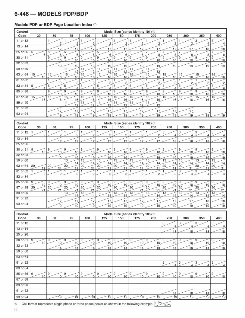
Wiring Diagram SelectionA. Field and Submittal Wiring Diagram Selection
Wiring in the field changes little when the brand of the controls furnished on the unit heater changes. Select correct wiring diagrams as follows:
1. Determine unit heater model and size.
2. Select control code number from Table 1.
3. Reference unit heater model in the Page Location Index with control code number and determine correct page number for single-phase or three-phase control. Single-phase wiring diagram page numbers are in the upper left of box and three-phase diagrams are in the lower right of box.
4. Wiring diagrams for unit heater accessories are listed in Table 2. Use the accessory diagrams along with the unit wiring diagrams for complete wiring instructions.
B. Service and Troubleshooting
Because internal or factory wiring may vary depending on controls manufacturer, the wiring diagrams must be selected with the series identity number when servicing or troubleshooting a unit heater control system. Wiring diagrams in this bulletin are for unit heaters manufactured after June 2003 and the series identity number is the 5th thru the 7th digits of the unit heater serial number.
EXAMPLE: Serial No. – 01121010697 has a series identity number of 101.
To select the correct wiring diagram:
1. Determine unit heater model and size from serial plate located on the side of the unit.
2. Determine the control code numbers from box marked Control Code, also on the serial plate.
3. Determine the series identity number of the unit heater, then proceed with Step 3 of Field and Submittal Wiring Diagram Selection.
Example SelectionSelect correct single-phase wiring diagram for a PDP175A Control Code 11, series identity number 101.
Locate the Page Location Index which shows the page numbers for PDP and BDP units with series identity number 101 (see page iii). Select the page number where the column for the PDP175 intersects with the line for control code 11. The correct single phase wiring diagram for this unit is found on page 1 in the upper left portion of box. If the unit also had a summer/winter switch the accessory wiring diagram found on page C-2 as per Table 2, would also be required for complete wiring information.
Two-in-one DiagramsTwo wiring diagrams are furnished for each circuit configuration in this manual. Included are a connection diagram at the left for field installation and circuit schematic at the right to aid in continuity and trouble shooting.
The heavier lines in the connection diagram indicate line voltage; the lighter lines indicate low voltage. Solid lines show pre-wiring performed at the factory; dotted lines inform the installer of connections required to put the heater in operation.
Table 1 Control Code Descriptions
Control Code Number Description
11,12,13,14 Single-Stage, Standing Pilot, 100% Shut-Off, Natural Gas
81,82,91,92 Single-Stage, Standing Pilot, 100% Shut-Off, Propane Gas
25,26 Two-Stage, Standing Pilot, 100% Shut-Off, Natural Gas
83,84 Two-Stage, Standing Pilot, 100% Shut-Off, Propane Gas
30,31,32,33 Single-Stage, Intermittent Pilot Ignition, 100% Shut-Off with Continuous Retry, Natural Gas
85,86,93,94 Single-Stage, Intermittent Pilot Ignition, 100% Shut-Off with Continuous Retry, Propane Gas
59,60 Mechanical Modulation with Automatic Pilot Ignition, Non-100% Shut-Off, Natural Gas, BDP Only
89,90 Mechanical Modulation with Automatic Pilot Ignition, Non-100% Shut-Off, Propane Gas, BDP Only
63,64 Two-Stage, Intermittent Pilot Ignition, 100% Shut-Off with Continuous Retry, Natural Gas
87,88 Two-Stage, Intermittent Pilot Ignition, 100% Shut-Off with Continuous Retry, Propane Gas
Table 2Accessory Wiring Diagram Page Location Index ➀
Page Accessory
C-1 Energy-Saver Kit
C-2 Summer/Winter Switch➀ See paragraph A, step 4 under “Wiring Diagram Selection”.
6-446 — MODELS PDP/BDP
iii
Models PDP or BDP Page Location Index ➀
Control Model Size (series identity 101) ➀ Code 30 50 75 100 125 150 175 200 250 300 350 400
11 or 12 1 1 1 1 1 1 1 1 1 3 3 2 2 2 2 2 2 2 2 2 4 4 13 or 14 17 17 17 17 17 17 17 17 17 18 18 25 or 26 5 5 5 5 5 5 5 7 7 7 7 7 6 6 6 6 6 6 6 8 8 8 8 8 30 or 31 9 9 9 9 9 9 9 9 9 9 9 10 10 10 10 10 10 10 10 10 10 10 32 or 33 19 19 19 19 19 19 19 19 19 19 19 59 or 60 11 11 11 11 11 11 12 12 12 12 12 12 63 or 64 15 15 15 15 15 15 15 15 15 15 15 15 16 16 16 16 16 16 16 16 16 16 16 16 81 or 82 1 1 1 1 1 1 1 1 1 1 1 2 2 2 2 2 2 2 2 2 2 2 83 or 84 5 5 5 5 5 5 5 5 5 5 7 7 6 6 6 6 6 6 6 6 6 6 8 8 85 or 86 9 9 9 9 9 9 9 9 9 9 9 10 10 10 10 10 10 10 10 10 10 10 87 or 88 15 15 15 15 15 15 15 15 15 15 15 15 16 16 16 16 16 16 16 16 16 16 16 16 89 or 90 11 11 11 11 11 11 12 12 12 12 12 12 91 or 92 17 17 17 17 17 17 17 17 17 93 or 94 19 19 19 19 19 19 19 19 19 19 19
Control Model Size (series identity 102) ➀ Code 30 50 75 100 125 150 175 200 250 300 350 400
11 or 12 1 1 1 1 1 1 1 1 3 3 3 3 2 2 2 2 2 2 2 2 4 4 4 4 13 or 14 17 17 17 17 17 17 17 18 18 18 18 25 or 26 30 or 31 9 9 9 9 9 9 9 9 9 9 9 9 10 10 10 10 10 10 10 10 10 10 10 10 32 or 33 19 19 19 19 19 19 19 19 19 19 19 59 or 60 13 13 13 13 13 13 13 13 13 13 14 14 14 14 14 14 14 14 14 14 63 or 64 20 20 20 20 20 20 20 20 20 20 20 20 21 21 21 21 21 21 21 21 21 21 21 21 81 or 82 1 1 1 1 1 1 1 1 1 3 3 3 2 2 2 2 2 2 2 2 2 4 4 4 83 or 84 85 or 86 9 9 9 9 9 9 9 9 9 9 9 9 10 10 10 10 10 10 10 10 10 10 10 10 87 or 88 20 20 20 20 20 20 20 20 20 20 20 20 21 21 21 21 21 21 21 21 21 21 21 21 89 or 90 13 13 13 13 13 13 13 13 13 13 14 14 14 14 14 14 14 14 14 14 91 or 92 17 17 17 17 17 17 17 17 17 18 18 93 or 94 19 19 19 19 19 19 19 19 19 19 19
Control Model Size (series identity 103) ➀ Code 30 50 75 100 125 150 175 200 250 300 350 400
11 or 12 3 3 3 3 4 4 4 4 13 or 14 18 18 18 18 25 or 26 30 or 31 9 9 9 9 9 9 9 9 9 9 9 9 10 10 10 10 10 10 10 10 10 10 10 10 32 or 33 19 19 19 19 19 19 19 19 19 19 19 59 or 60 63 or 64 81 or 82 3 3 3 3 4 4 4 4 83 or 84 85 or 86 9 9 9 9 9 9 9 9 9 9 9 9 10 10 10 10 10 10 10 10 10 10 10 10 87 or 88 89 or 90 91 or 92 18 18 18 18 93 or 94 19 19 19 19 19 19 19 19 19 19 19
➀ Cell format represents single phase or three phase power as shown in the following example. 1-Ph3-Ph
6-446 — MODELS PDP/BDP
1
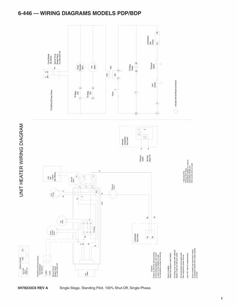
6-446 — WIRING DIAGRAMS MODELS PDP/BDP
5H78233C6 REV A Single-Stage, Standing Pilot, 100% Shut-Off, Single-Phase.
Com
bina
tion
Gas
Con
trol
TH
TR
Pre
ssur
e
Sw
itch
Lim
it
Con
trol
VC
Fan
Mot
or
TD
C
24
TD
Rel
ay
24V
115V
Xfm
r
GT
1
L2
(W)
L1
(BK
)C
ircui
t Bre
aker
(B
y O
ther
s)
Sec
ond
Circ
uit
Bre
aker
Req
'd.
For
230
V,20
0V,1
Ø
The
rm
t°
TD
Rel
ay
Hea
ter
HH
TD
Rel
ay
Pow
erE
xhau
ster
Mot
or3
1T
DC
Indi
cate
s Te
rmin
al B
oard
Con
nect
ion
T2
F
115V
/60H
z/1Ø
Pow
er S
how
n
Term
inal
Boa
rd "
G"
Pre
ssur
e
Sw
itch
Alte
rnat
e
Com
bina
tion
Gas
Con
trol
1 2
Com
bina
tion
Gas
Con
trol
TRTHB
L W
L
ow
V
olt
T
herm
(By
Oth
ers
)
W
115
V/6
0H
z/1
Ø P
ow
er
Sh
ow
n
Circu
it B
rea
ke
r
(
By O
the
rs)
Se
co
nd
Circu
it
Bre
ake
r R
eq
'd
For
230V
,200V
,1Ø
L1(B
K)
L2
(W)
BK
13 F
an
Moto
r
* 2
4V
X
FM
R
Te
rmin
al
Bo
ard
W
W BK
BL
BL
BL
GV
F
C
T2
T1
RB
L Lim
it
Co
ntr
ol
BL
Gn
d
Pre
ssure
Sw
itch
T-D
Rela
y
HH4
2
R
P
ow
er
Exh
au
st
M
oto
r
J-B
ox
C
aution
Fa
ilure
to
wire
th
is u
nit a
cco
rdin
g
to t
his
wirin
g d
iag
ram
ma
y r
esu
lt
in in
jury
to
th
e in
sta
ller
or
use
r.
Fo
r d
evia
tio
ns c
on
tact
the
fa
cto
ry.
No
te t
o in
sta
ller:
Att
ach
th
is d
iag
ram
ne
ar
he
ate
r.
All
wirin
g m
ust
co
mp
ly w
ith
na
tio
na
l
ele
ctr
ic c
od
e a
nd
all
loca
l co
de
s.
All
co
mp
on
en
ts m
ust
ag
ree
with
the
ir r
esp
ective
po
we
r so
urc
e.
Use
10
5°
wire
fo
r re
pla
ce
me
nts
.
* A
lte
rna
te X
fmr.
Prim
ary
Xfm
r W
ire
s
23
0V
/60
Hz/1
Ø-B
K &
Y (
OR
O)
20
0V
/60
Hz/1
Ø-B
K &
R
Wire
nu
t th
e w
ire
no
t u
se
d.
UN
IT H
EA
TE
R W
IRIN
G D
IAG
RA
MFA
CT
OR
Y
FIE
LD
WIR
E N
UT
24
V.
LIN
E
WIR
ING
LE
GE
ND
So
me
mo
de
ls m
ay h
ave
lim
it c
on
tro
lto
pre
ssu
re s
witch
wire
ro
ute
d o
uts
ide
o
f J-b
ox.
2
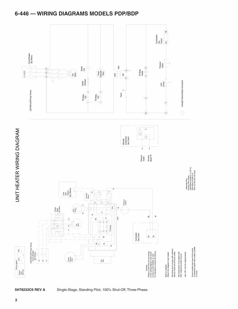
6-446 — WIRING DIAGRAMS MODELS PDP/BDP
5H78233C6 REV A Single-Stage, Standing Pilot, 100% Shut-Off, Three-Phase.
Alte
rnat
e
Com
bina
tion
Gas
Con
trol
1 2
Term
inal
Boa
rd "
G"
Pre
ssur
e
Sw
itch
Pre
ssure
Sw
itch
WBL
TRTH
Com
bina
tion
Gas
Con
trol
L
ow
V
olt
T
herm
(By
Oth
ers
)
TR
TH
Com
bina
tion
Gas
Con
trol
Pre
ssur
e
Sw
itch
Lim
it
Con
trol
VC
Pow
erE
xhau
ster
Mot
or
TD
C
13
TD
Rel
ay
24V
230V
Xfm
r
GT
1
TD
Rel
ay
L3L2
L1
C
ircui
t Bre
aker
(
By
Oth
ers)
L1 L
2 L3
TD
Rel
ay
Hea
ter
HH
The
rmt°
Sta
rter
Coi
lS
tart
er
Ove
rload
31
TD
C
FT
2
Indi
cate
d Te
rmin
al B
oard
Con
nect
ion
Fan
Mot
or
230V
/60H
z/3Ø
Pow
er S
how
n
No
te t
o in
sta
ller:
Att
ach
th
is d
iag
ram
ne
ar
he
ate
r.
All
wirin
g m
ust
co
mp
ly w
ith
na
tio
na
l
ele
ctr
ic c
od
e a
nd
all
loca
l co
de
s.
All
co
mp
on
en
ts m
ust
ag
ree
with
the
ir r
esp
ective
po
we
r so
urc
e.
Use
10
5°
wire
fo
r re
pla
ce
me
nts
.
C
aution
Fa
ilure
to
wire
th
is u
nit a
cco
rdin
g
to t
his
wirin
g d
iag
ram
ma
y r
esu
lt
in in
jury
to
th
e in
sta
ller
or
use
r.
Fo
r d
evia
tio
ns c
on
tact
the
fa
cto
ry.
* A
lte
rna
te X
fmr
Prim
ary
Xfm
r W
ire
s
23
0V
/60
Hz/1
Ø-B
K &
Y (
OR
O)
20
0V
/60
Hz/1
Ø-B
K &
R
Wire
nu
t th
e w
ire
no
t u
se
d.
3 P
hase
Sta
rter
(By
Oth
ers)
* 2
4V
X
fmr
23
0V
/60
Hz/
3Ø
Po
we
r S
ho
wn
C
ircu
it B
rea
ker
(
By
Oth
ers
)
L1
L2
L3
BR
BK
Facto
ry
Fie
ld
Wire N
ut
24
V.
Lin
e
Wirin
g L
egend
C
L3
L2
L1
Fan
Moto
r
T3
T2
T1
BL
J-B
ox
Te
rmin
al
Bo
ard
W
OBK
BL
BL
BL
GV
F
C
T2
T1
RB
L Lim
it
Co
ntr
ol
Gn
d
R
13
T-D
Rela
y
HH4
2
P
ow
er
Exh
au
st
M
oto
r
UN
IT H
EA
TE
R W
IRIN
G D
IAG
RA
M
W
So
me
mo
de
ls m
ay h
ave
lim
it c
on
tro
lto
pre
ssu
re s
witch
wire
ro
ute
d o
uts
ide
o
f J-b
ox.
3
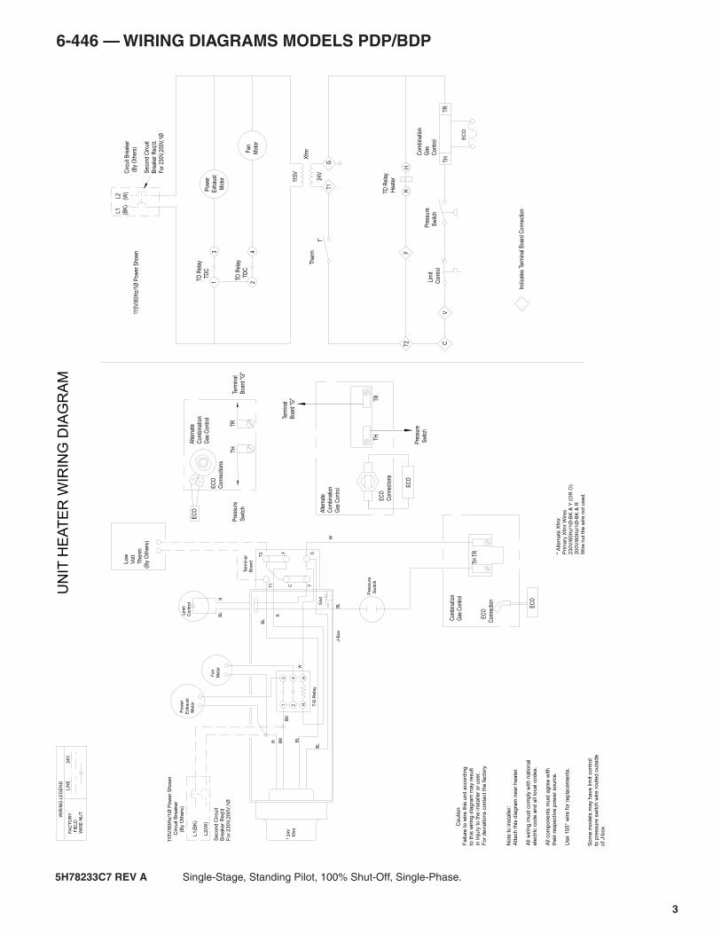
6-446 — WIRING DIAGRAMS MODELS PDP/BDP
5H78233C7 REV A Single-Stage, Standing Pilot, 100% Shut-Off, Single-Phase.
3
TD
Rel
ay
TD
C
42
TD
Rel
ay
TD
C
1
EC
O
TR
Com
bina
tion
Gas
Con
trol
TH
E
CO
Con
nect
ion
EC
O
TH T
R
Com
bina
tion
Gas
Con
trol
L
ow
V
olt
T
herm
(By
Oth
ers
)
C
aution
Fa
ilure
to
wire
th
is u
nit a
cco
rdin
g
to t
his
wirin
g d
iag
ram
ma
y r
esu
lt
in in
jury
to
th
e in
sta
ller
or
use
r.
Fo
r d
evia
tio
ns c
on
tact
the
fa
cto
ry.
Pow
erE
xhau
st
Mot
or
V
L2
(W)
L1
(BK
)
115V
/60H
z/1Ø
Pow
er S
how
n
Sec
ond
Circ
uit
Bre
aker
Req
'd.
For
230
V,20
0V,1
Ø
Circ
uit B
reak
er
(B
y O
ther
s)
t°
The
rm
T1
G
C
F
Xfm
r
115V
24V
T2
Lim
it
Con
trol
Indi
cate
s Te
rmin
al B
oard
Con
nect
ion
Pre
ssur
e
Sw
itch
Fan
Mot
or
HH
TD
Rel
ay
Hea
ter
No
te t
o in
sta
ller:
Att
ach
th
is d
iag
ram
ne
ar
he
ate
r.
All
wirin
g m
ust
co
mp
ly w
ith
na
tio
na
l
ele
ctr
ic c
od
e a
nd
all
loca
l co
de
s.
All
co
mp
on
en
ts m
ust
ag
ree
with
the
ir r
esp
ective
po
we
r so
urc
e.
Use
10
5°
wire
fo
r re
pla
ce
me
nts
.
* A
lte
rna
te X
fmr.
Prim
ary
Xfm
r W
ire
s
23
0V
/60
Hz/1
Ø-B
K &
Y (
OR
O)
20
0V
/60
Hz/1
Ø-B
K &
R
Wire
nu
t th
e w
ire
no
t u
se
d.
W
115
V/6
0H
z/1
Ø P
ow
er
Sh
ow
n
Circu
it B
rea
ke
r
(
By O
the
rs)
Se
co
nd
Circu
it
Bre
ake
r R
eq
'd
For
230V
,200V
,1Ø
L1(B
K)
L2
(W)
UN
IT H
EA
TE
R W
IRIN
G D
IAG
RA
M
BK
13
FA
CT
OR
Y
FIE
LD
WIR
E N
UT
24
V.
LIN
E
WIR
ING
LE
GE
ND
Fan
Moto
r
* 2
4V
X
fmr
Te
rmin
al
Bo
ard
W
W BK
BL
BL
BL
GV
F
C
T2
T1
RB
L Lim
it
Co
ntr
ol
BL
Gn
d
Pre
ssure
Sw
itch
T-D
Rela
y
HH4
2
R
P
ow
er
Exh
au
st
M
oto
r
J-B
ox
THTR
EC
O
Con
nect
ions
EC
O
Gas
Con
trol
Com
bina
tion
Alte
rnat
e
Sw
itch
Pre
ssur
e
Boa
rd "G
"
Term
inal
Con
nect
ions
EC
O
Boa
rd "
G"
Term
inal
Sw
itch
Pre
ssur
e
Gas
Con
trol
Com
bina
tion
Alte
rnat
eE
CO
TR
TH
So
me
mo
de
ls m
ay h
ave
lim
it c
on
tro
lto
pre
ssu
re s
witch
wire
ro
ute
d o
uts
ide
o
f J-b
ox
4
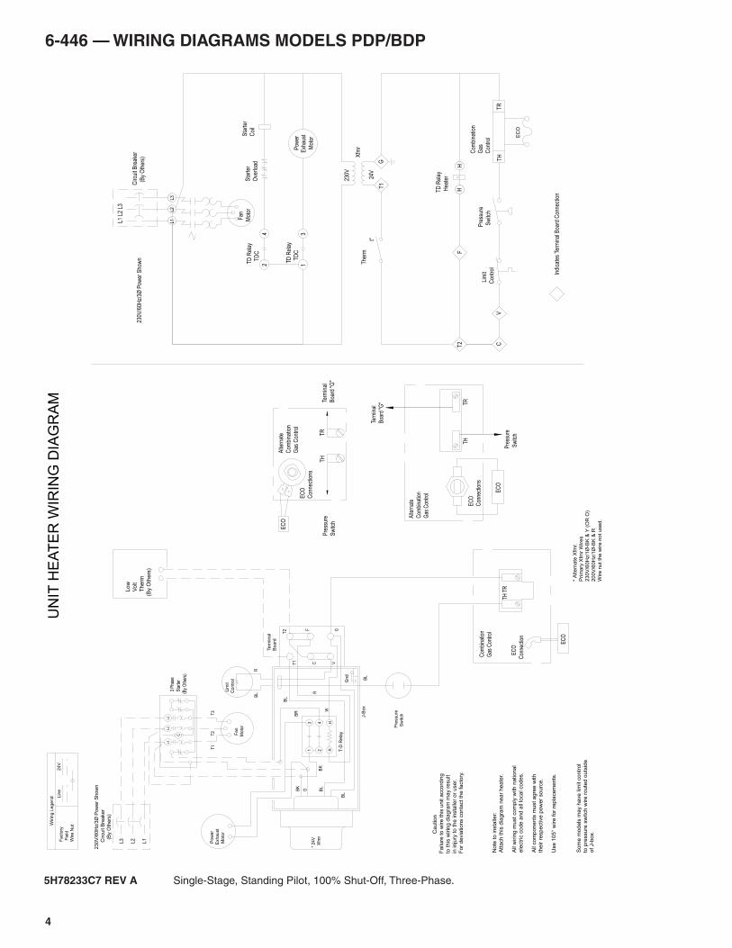
6-446 — WIRING DIAGRAMS MODELS PDP/BDP
5H78233C7 REV A Single-Stage, Standing Pilot, 100% Shut-Off, Three-Phase.
FH
H
TD
Rel
ay
Hea
ter
t°
The
rm
T2 C
V
Lim
it
Con
trol
Pre
ssur
e
Sw
itch
TH
EC
O
TR
Com
bina
tion
Gas
Con
trol
Fan
Mot
or
L3L2
L1
Circ
uit B
reak
er
(B
y O
ther
s)
L1 L
2 L3
230V
/60H
z/3Ø
Pow
er S
how
n
Sta
rter
Coi
lS
tart
er
Ove
rload
T1
G
Xfm
r
230V
24V
Pow
erE
xhau
st
Mot
or
EC
O
TH T
R
E
CO
Con
nect
ion
Com
bina
tion
Gas
Con
trol
L
ow
V
olt
T
herm
(By
Oth
ers
)
No
te t
o in
sta
ller:
Att
ach
th
is d
iag
ram
ne
ar
he
ate
r.
All
wirin
g m
ust
co
mp
ly w
ith
na
tio
na
l
ele
ctr
ic c
od
e a
nd
all
loca
l co
de
s.
All
co
mp
on
en
ts m
ust
ag
ree
with
the
ir r
esp
ective
po
we
r so
urc
e.
Use
10
5°
wire
fo
r re
pla
ce
me
nts
.
C
aution
Fa
ilure
to
wire
th
is u
nit a
cco
rdin
g
to t
his
wirin
g d
iag
ram
ma
y r
esu
lt
in in
jury
to
th
e in
sta
ller
or
use
r.
Fo
r d
evia
tio
ns c
on
tact
the
fa
cto
ry.
* A
lte
rna
te X
fmr.
Prim
ary
Xfm
r W
ire
s
23
0V
/60
Hz/1
Ø-B
K &
Y (
OR
O)
20
0V
/60
Hz/1
Ø-B
K &
R
Wire
nu
t th
e w
ire
no
t u
se
d.
3 P
hase
Sta
rter
(By
Oth
ers)
* 2
4V
X
fmr
Pre
ssure
Sw
itch
Indi
cate
s Te
rmin
al B
oard
Con
nect
ion
3
TD
Rel
ay
TD
C
124
TD
Rel
ay
TD
C
23
0V
/60
Hz/
3Ø
Po
we
r S
ho
wn
C
ircu
it B
rea
ker
(
By
Oth
ers
)
L1
L2
L3
BR
BK
Facto
ry
Fie
ld
Wire N
ut
24
V.
Lin
e
Wirin
g L
egend
C
L3
L2
L1
Fan
Moto
r
T3
T2
T1
BL
J-B
ox
Te
rmin
al
Bo
ard
W
OBK
BL
BL
BL
GV
F
C
T2
T1
RB
L Lim
it
Co
ntr
ol
Gn
d
R
13
T-D
Rela
y
HH4
2
P
ow
er
Exh
au
st
M
oto
r
UN
IT H
EA
TE
R W
IRIN
G D
IAG
RA
M
Gas
Con
trol
Com
bina
tion
Alte
rnat
e
Boa
rd "G
"
Term
inal
TRTH
Sw
itch
Pre
ssur
e
Con
nect
ions
EC
O
EC
O
TH
TR
EC
OA
ltern
ate
Com
bina
tion
Gas
Con
trol
Pre
ssur
e
Sw
itch
Term
inal
Boa
rd "
G"
EC
O
Con
nect
ions
So
me
mo
de
ls m
ay h
ave
lim
it c
on
tro
lto
pre
ssu
re s
witch
wire
ro
ute
d o
uts
ide
o
f J-b
ox.
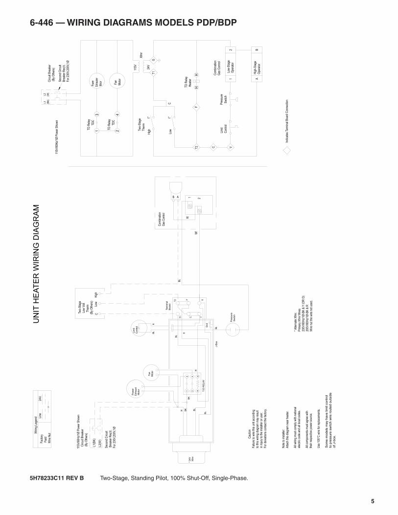
5
6-446 — WIRING DIAGRAMS MODELS PDP/BDP
5H78233C11 REV B Two-Stage, Standing Pilot, 100% Shut-Off, Single-Phase.
J-B
ox
P
ow
er
Exh
au
st
M
oto
r
R
24 H
H T-D
RE
LA
Y
Gn
d
BL
Lim
it
Co
ntr
ol
BL
R
T1
T2
C
F
VG
BL
BL
BL
BK
W
W
Te
rmin
al
Bo
ard
* 24V
X
fmr
Fan
Moto
r
31
BK
Wiri
ng L
egen
d Line
24V.
Fac
tory
Fie
ld
Wire
Nut
* A
ltern
ate
Xfm
r.
Prim
ary
Xfm
r W
ires
230V
/60H
z/1Ø
-BK
& Y
(O
R O
)
200V
/60H
z/1Ø
-BK
& R
Wire
nut
the
wire
not
use
d.
Cau
tion
Fai
lure
to w
ire th
is u
nit a
ccor
ding
to th
is w
iring
dia
gram
may
res
ult
in in
jury
to th
e in
stal
ler
or u
ser.
For
dev
iatio
ns c
onta
ct th
e fa
ctor
y.
Not
e to
inst
alle
r:
Atta
ch th
is d
iagr
am n
ear
heat
er.
All
wiri
ng m
ust c
ompl
y w
ith n
atio
nal
elec
tric
cod
e an
d al
l loc
al c
odes
.
All
com
pone
nts
mus
t agr
ee w
ith
thei
r re
spec
tive
pow
er s
ourc
e.
Use
105
°C w
ire fo
r re
plac
emen
ts.
21
Low
-Sta
ge
Ope
rato
r
Two-
Sta
ge
The
rm
t°
TD
Rel
ay
Hea
ter
HH
UN
IT H
EA
TE
R W
IRIN
G D
IAG
RA
M
Pre
ssur
e
Sw
itch
Indi
cate
s Te
rmin
al B
oard
Con
nect
ion
Lim
it
Con
trol
T2
F
C
BL
t°
Hig
h
Low
BA
Hig
h-S
tage
Ope
rato
r
C
115V
/60H
z/1Ø
Pow
er S
how
n
C
ircui
t Bre
aker
(B
y O
ther
s)
Sec
ond
Circ
uit
Bre
aker
Req
'd.
For
230
V,20
0V,1
Ø
L1(B
K)
L2(W
)
Circ
uit B
reak
er
(B
y O
ther
s)
Sec
ond
Circ
uit
Bre
aker
Req
'd.
For
230
V,20
0V,1
Ø
115V
/60H
z/1Ø
Pow
er S
how
n
L1
(BK
)
L2
(W)
T1
G
Xfm
r
115V
24V
21B A
W
Com
bina
tion
Gas
Con
trol
V
Com
bina
tion
Gas
Con
trol
(By
Oth
ers)
T
herm
Low
Vol
t
Tw
o-S
tage
CLo
wH
igh
Som
e m
odels
may h
ave lim
it c
ontr
ol
to p
ressu
re s
witch
wire
ro
ute
d o
uts
ide
of J-b
ox.
W
Sw
itch
Pre
ssure
Fan
Mot
or
TD
C
24
TD
Rel
ay
TD
Rel
ay
Pow
er
Exha
uste
r
Mot
or3
1T
DC
6
6-446 — WIRING DIAGRAMS MODELS PDP/BDP
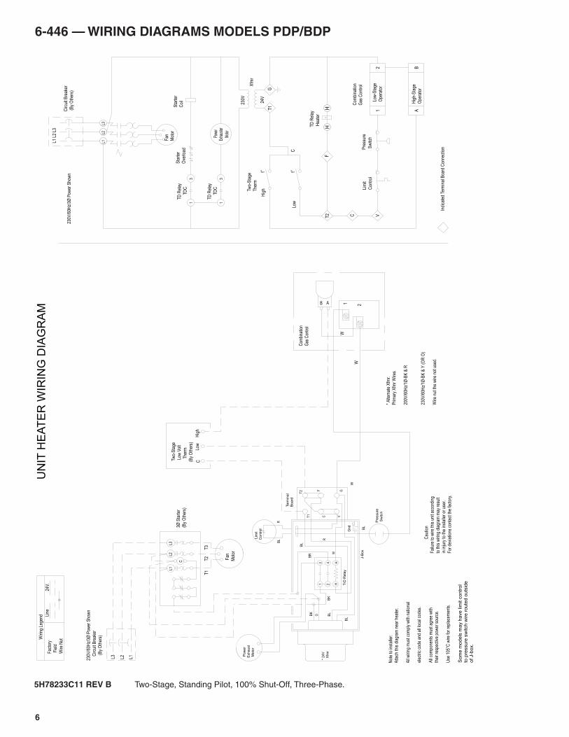
5H78233C11 REV B Two-Stage, Standing Pilot, 100% Shut-Off, Three-Phase.
Coi
l
Sta
rter
TD
C
13
Ove
rload
Sta
rter
TD
Rel
ay
TD
Rel
ay
31
TD
C
Mot
or
Exha
uste
r P
ower
24 H
H T-D
Rela
y
31
R
Gn
d
BL
R
T1
T2
C
F
VG
BL
BL
BL
BK
O
W
Bo
ard
Te
rmin
al
J-B
ox
BL
BK
BR
X
fmr
* 2
4V
Sw
itch
Pre
ssure
Co
ntr
ol
Lim
it
P
ow
er
Exh
au
st
M
oto
r
C
L3L2
L1
Not
e to
inst
alle
r:
Atta
ch th
is d
iagr
am n
ear
heat
er.
All
wiri
ng m
ust c
ompl
y w
ith n
atio
nal
elec
tric
cod
e an
d al
l loc
al c
odes
.
All
com
pone
nts
mus
t agr
ee w
ith
thei
r re
spec
tive
pow
er s
ourc
e.
Use
105
°C w
ire fo
r re
plac
emen
ts.
Cau
tion
Fai
lure
to w
ire th
is u
nit a
ccor
ding
to th
is w
iring
dia
gram
may
res
ult
in in
jury
to th
e in
stal
ler
or u
ser.
For
dev
iatio
ns c
onta
ct th
e fa
ctor
y.
Wiri
ng L
egen
d Line
24V.
Fac
tory
Fie
ld
Wire
Nut
T1
T2
T3
Fan
Mot
or
3Ø S
tart
er
(By
Oth
ers)
L3L2
L1
UN
IT H
EA
TE
R W
IRIN
G D
IAG
RA
M
Indi
cate
d Te
rmin
al B
oard
Con
nect
ion
Fan
TD
Rel
ay
Hea
ter
HH
Pre
ssur
e
Sw
itch
Lim
it
Con
trol
T2
F
C
230V
/60H
z/3Ø
Pow
er S
how
n
C
ircui
t Bre
aker
(
By
Oth
ers)
L3 L2 L1
C
ircui
t Bre
aker
(
By
Oth
ers)
L1 L
2 L3
230V
/60H
z/3Ø
Pow
er S
how
n
Hig
hLo
wC T
wo-
Sta
ge
Low
Vol
t
T
herm
(By
Oth
ers)
V2
1Lo
w-S
tage
Ope
rato
r
BA
Hig
h-S
tage
Ope
rato
r
Com
bina
tion
Gas
Con
trol
24V
230V
Xfm
r
GT
1
CLo
w
Hig
h
t°t°
The
rm
Two-
Sta
ge
Mot
or
Wire
nut
the
wire
not
use
d.
200V
/60H
z/1Ø
-BK
& R
230V
/60H
z/1Ø
-BK
& Y
(O
R O
)
Prim
ary
Xfm
r W
ires
* A
ltern
ate
Xfm
r.
Gas
Con
trol
Com
bina
tion
W
AB 1 2W
W
So
me
mo
de
ls m
ay h
ave
lim
it c
on
tro
lto
pre
ssu
re s
witch
wire
ro
ute
d o
uts
ide
o
f J-b
ox.
7
6-446 — WIRING DIAGRAMS MODELS PDP/BDP
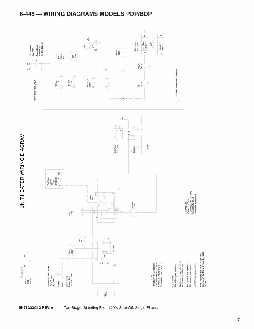
5H78233C12 REV A Two-Stage, Standing Pilot, 100% Shut-Off, Single-Phase.
J-B
ox
R
24 H
H T-D
Rela
y
Sw
itch
Pre
ssu
re
Gn
d
BL
T1
T2
C
F
VG
BL
BL
BL
BK
W
W
Bo
ard
Te
rmin
al
X
FM
R
* 24V
31
BK
W
M
oto
r
Exh
au
st
P
ow
er
Fan
Moto
r
Lim
it
Co
ntr
ol
RB
L
So
me
mo
de
ls m
ay h
ave
lim
it c
on
tro
l to
pre
ssu
re s
witch
wire
ro
ute
d o
uts
ide
o
f J-b
ox.
Wiri
ng L
egen
d Line
24V.
Fac
tory
Fie
ld
Wire
Nut
* A
ltern
ate
Xfm
r.
Prim
ary
Xfm
r W
ires
230V
/60H
z/1Ø
-BK
& Y
(O
R O
)
200V
/60H
z/1Ø
-BK
& R
Wire
nut
the
wire
not
use
d.
Cau
tion
Fai
lure
to w
ire th
is u
nit a
ccor
ding
to th
is w
iring
dia
gram
may
res
ult
in in
jury
to th
e in
stal
ler
or u
ser.
For
dev
iatio
ns c
onta
ct th
e fa
ctor
y.
Not
e to
inst
alle
r:
Atta
ch th
is d
iagr
am n
ear
heat
er.
All
wiri
ng m
ust c
ompl
y w
ith n
atio
nal
elec
tric
cod
e an
d al
l loc
al c
odes
.
All
com
pone
nts
mus
t agr
ee w
ith
thei
r re
spec
tive
pow
er s
ourc
e.
Use
105
°C w
ire fo
r re
plac
emen
ts.
UN
IT H
EA
TE
R W
IRIN
G D
IAG
RA
M
Indi
cate
s Te
rmin
al B
oard
Con
nect
ion
Low
-Sta
ge
Ope
rato
r
Two-
Sta
ge
The
rm
t°
TD
Rel
ay
Hea
ter
HH
Pre
ssur
e S
witc
hLi
mit
Con
trol
T2
F
C
t°
Hig
h
Low
BA
Hig
h-S
tage
Ope
rato
r
C
TR
TH
EC
O
115V
/60H
z/1Ø
Pow
er S
how
n
C
ircui
t Bre
aker
(B
y O
ther
s)
Sec
ond
Circ
uit
Bre
aker
Req
'd.
For
230
V,20
0V,1
Ø
L1(B
K)
L2(W
)
Circ
uit B
reak
er
(B
y O
ther
s)
Sec
ond
Circ
uit
Bre
aker
Req
'd.
For
230
V,20
0V,1
Ø
115V
/60H
z/1Ø
Pow
er S
how
n
L1
(BK
)
L2
(W)
T1
G
Xfm
r
115V
24V
V
BA
TH T
R
W
Com
bina
tion
Gas
Con
trol
E
CO
Con
nect
ion
EC
O
Com
bina
tion
Gas
Con
trol
(By
Oth
ers)
T
herm
Low
Vol
t
Tw
o-S
tage
CLo
wH
igh
Fan
Mot
or
TD
C
24
TD
Rel
ay
TD
Rel
ay
Pow
er
Exha
uste
r
Mot
or3
1T
DC
8
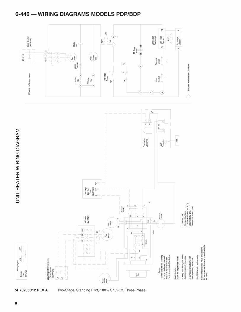
6-446 — WIRING DIAGRAMS MODELS PDP/BDP
5H78233C12 REV A Two-Stage, Standing Pilot, 100% Shut-Off, Three-Phase.
Pow
er
Exha
uste
r
Mot
or
TD
C
13
TD
Rel
ay
TD
Rel
ayS
tart
er
Ove
rload
31
TD
C
24 H
H T-D
Rela
y
31
R
Gn
d
BL
R
T1
T2
C
F
VG
BL
BL
BL
BK
O
W
Bo
ard
Te
rmin
al
J-B
ox
BL
BK
BR
X
fmr
* 2
4V
Sw
itch
Pre
ssure
Co
ntr
ol
Lim
it
P
ow
er
Exh
au
st
M
oto
r
W
So
me
mo
de
ls m
ay h
ave
lim
it c
on
tro
lto
pre
ssu
re s
witch
wire
ro
ute
d o
uts
ide
o
f J-b
ox.
C
L3L2
L1
* A
ltern
ate
Xfm
r.
Prim
ary
Xfm
r W
ires
230V
/60H
z/1Ø
-BK
& Y
(O
R O
)
200V
/60H
z/1Ø
-BK
& R
Wire
nut
the
wire
not
use
d.
Not
e to
inst
alle
r:
Atta
ch th
is d
iagr
am n
ear
heat
er.
All
wiri
ng m
ust c
ompl
y w
ith n
atio
nal
elec
tric
cod
e an
d al
l loc
al c
odes
.
All
com
pone
nts
mus
t agr
ee w
ith
thei
r re
spec
tive
pow
er s
ourc
e.
Use
105
°C w
ire fo
r re
plac
emen
ts.
Cau
tion
Fai
lure
to w
ire th
is u
nit a
ccor
ding
to th
is w
iring
dia
gram
may
res
ult
in in
jury
to th
e in
stal
ler
or u
ser.
For
dev
iatio
ns c
onta
ct th
e fa
ctor
y.
Wiri
ng L
egen
d Line
24V.
Fac
tory
Fie
ld
Wire
Nut
230V
/60H
z/3Ø
Pow
er S
how
n
C
ircui
t Bre
aker
(
By
Oth
ers)
L3 L2 L1
T1
T2
T3
Fan
Mot
or
3Ø S
tart
er
(By
Oth
ers)
L3L2
L1
C
ircui
t Bre
aker
(
By
Oth
ers)
L1 L
2 L3
UN
IT H
EA
TE
R W
IRIN
G D
IAG
RA
M
Indi
cate
d Te
rmin
al B
oard
Con
nect
ion
Fan
Mot
or
230V
/60H
z/3Ø
Pow
er S
how
n
Two-
Sta
ge
The
rm
t°
TD
Rel
ay
Hea
ter
HH
Pre
ssur
e
Sw
itch
Lim
it
Con
trol
T2
F
C
t°
Hig
h
Low
C
Hig
hLo
wC T
wo-
Sta
ge
Low
Vol
t
T
herm
(By
Oth
ers)
T1
G
Xfm
r
230V
24V
V
BA
TH T
R
W
Com
bina
tion
Gas
Con
trol
E
CO
Con
nect
ion
EC
O
Low
-Sta
ge
Ope
rato
r
BA
Hig
h-S
tage
Ope
rato
r
TR
TH
EC
O
Com
bina
tion
Gas
Con
trol
Sta
rter
Coi
l
6-446 — WIRING DIAGRAMS MODELS PDP/BDP
t°
The
rm
H
TD
Rel
ay
Hea
ter
HF
TD
Rel
ay
TD
C4
2
3
TD
Rel
ay
TD
C
1
W
115
V/6
0H
z/1
Ø P
ow
er
Sh
ow
n
Circu
it B
rea
ke
r
(
By O
the
rs)
Se
co
nd
Circu
it
Bre
ake
r R
eq
'd
Fo
r 2
30
V,2
00
V,1
Ø
L1(B
K)
L2
(W)
BK
13 F
an
Moto
r
* 24V
X
fmr
Te
rmin
al
Board
W
W BK
BL
BL
BL
GV
F
C
T2
T1
RB
L Lim
it
Contr
ol
BL
Gn
d
Pre
ssu
re
Sw
itch
T-D
Rela
y
HH4
2
R
P
ow
er
Exhaust
M
oto
r
J-B
ox
C
aution
Failu
re to w
ire this
unit a
ccord
ing
to this
wirin
g d
iagra
m m
ay r
esult
in inju
ry t
o t
he insta
ller
or
user.
For
devia
tions c
onta
ct th
e facto
ry.
Pow
er
Exh
aust
Mot
or
V
L2
(W)
L1
(BK
)
115V
/60H
z/1Ø
Pow
er S
how
n
Sec
ond
Circ
uit
Bre
aker
Req
'd.
For
230
V,20
0V,1
Ø
Circ
uit B
reak
er
(B
y O
ther
s)
T1
G
C
Xfm
r
115V
24V
T2
Lim
it
Con
trol
Indi
cate
s Te
rmin
al B
oard
Con
nect
ion
Pre
ssur
e
Sw
itch
Fan
Mot
or
No
te t
o in
sta
ller:
Att
ach
th
is d
iag
ram
ne
ar
he
ate
r.
All
wirin
g m
ust
co
mp
ly w
ith
na
tio
na
l
ele
ctr
ic c
od
e a
nd
all
loca
l co
de
s.
All
co
mp
on
en
ts m
ust
ag
ree
with
the
ir r
esp
ective
po
we
r so
urc
e.
Use
10
5°
wire
fo
r re
pla
ce
me
nts
.
* A
ltern
ate
Xfm
r.
Prim
ary
Xfm
r W
ires
230V
/60H
z/1
Ø-B
K &
Y (
OR
O)
200V
/60H
z/1
Ø-B
K &
R
Wire n
ut th
e w
ire n
ot used.
UN
IT H
EA
TE
R W
IRIN
G D
IAG
RA
MFA
CT
OR
Y
FIE
LD
WIR
E N
UT
24V
.LIN
E
WIR
ING
LE
GE
ND
D D
TH T
R
W
Gas
Con
trol
Com
bina
tion
Alte
rnat
e
PV
PV
/MV
MV
Com
bina
tion
Gas
Con
trol
Pilo
t
Opera
tor
Ma
in
Opera
tor
P M
C
RBL
YWGO
Igni
tor
BK
RBL
YWGO
Igni
tor
RBL
YWGO
Igni
tor
BK
Igni
tor
ROBE
RTSH
AWHO
NEYW
ELL
MV
MV
SPA
RK
24V
PV
MV
/PV
24V
(GN
D)
GN
D
PV
SPA
RK
PV
/MV
TR
(GN
D)
GN
D
ROBE
RTSH
AWHO
NEYW
ELL
MV
MV
SPA
RK
24V
PV
MV
/PV
24V
(GN
D)
GN
D
TH
(24V
)
PV
SPA
RK
PV
/MV
TR
(GN
D)
GN
D
ROBE
RTSH
AWHO
NEYW
ELL
MV
MV
SPA
RK
24V
PV
MV
/PV
24V
(GN
D)
GN
D
TH
(24V
)
PV
SPA
RK
PV
/MV
TR
(GN
D)
GN
D
ROBE
RTSH
AWHO
NEYW
ELL
MV
MV
SPA
RK
24V
PV
MV
/PV
24V
(GN
D)
GN
D
TH
(24V
)
PV
SPA
RK
PV
/MV
TR
(GN
D)
GN
D
IGNITION CONTROLLER IGNITION CONTROLLER
IGNITION CONTROLLER IGNITION CONTROLLERS
om
e m
od
els
ma
y h
ave
lim
it c
on
tro
l to
pre
ssu
re s
witch
wire
ro
ute
d o
uts
ide
o
f J-b
ox.
(PV
)
(MV
)(M
V/P
V)
(By
Oth
ers
)
T
herm
V
olt
L
ow
MV
PV
/MV
PV
W
Alte
rnat
e
Com
bina
tion
Gas
Con
trol
43
12
MV
MV
/PV
PV
M
1
C
2
P 3
CO
MB
INA
TIO
N G
AS
CO
NT
RO
L
HO
NE
YW
EL
LR
OB
ER
TS
HA
W
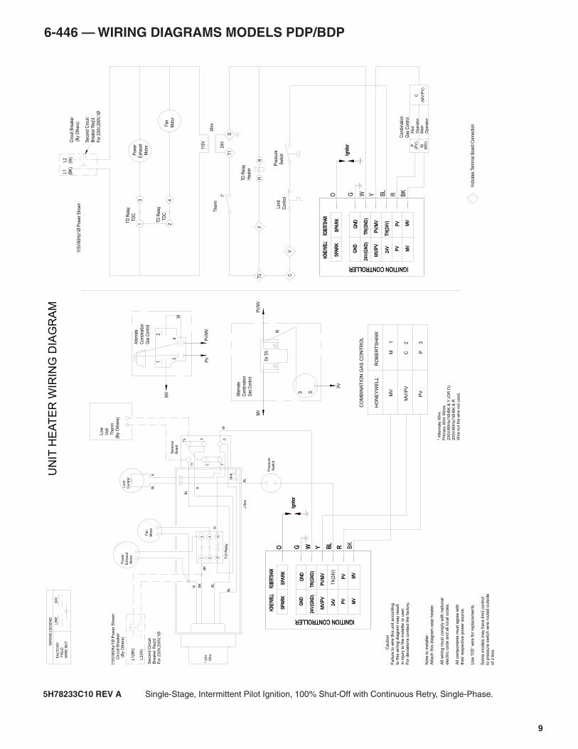
5H78233C10 REV A Single-Stage, Intermittent Pilot Ignition, 100% Shut-Off with Continuous Retry, Single-Phase.
9
10
6-446 — WIRING DIAGRAMS MODELS PDP/BDP
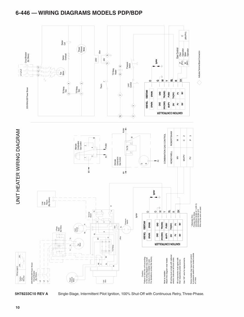
5H78233C10 REV A Single-Stage, Intermittent Pilot Ignition, 100% Shut-Off with Continuous Retry, Three-Phase.
t°
The
rm
Igni
tor
Pre
ssure
Sw
itch
W
Te
rmin
al
Bo
ard
L
ow
V
olt
T
herm
(By
Oth
ers
)
TD
Rel
ay
Hea
ter
HH
F
TD
Rel
ay
TD
C
42
3
TD
Rel
ay
TD
C
1
Fan
Mot
or
L3L2
L1
Circ
uit B
reak
er
(B
y O
ther
s)
L1 L
2 L3
230V
/60H
z/3Ø
Pow
er S
how
n
Sta
rter
Coi
lS
tart
er
Ove
rload
V
T1
G
C
Xfm
r
230V
24V
T2
Lim
it
Con
trol
Indi
cate
s Te
rmin
al B
oard
Con
nect
ion
Pre
ssur
e
Sw
itch
Pow
erE
xhau
st
Mot
or
Note
to insta
ller:
Attach this
dia
gra
m n
ear
heate
r.
All
wirin
g m
ust
com
ply
with n
ational
ele
ctr
ic c
ode a
nd a
ll lo
cal codes.
All
com
ponents
must agre
e w
ith
the
ir r
esp
ective
po
we
r so
urc
e.
Use 1
05°
wire for
repla
cem
ents
.
C
aution
Failu
re to w
ire this
unit a
ccord
ing
to this
wirin
g d
iagra
m m
ay r
esult
in inju
ry t
o t
he insta
ller
or
user.
For
devia
tions c
onta
ct th
e facto
ry.
* A
lte
rna
te X
fmr.
Prim
ary
Xfm
r W
ire
s
23
0V
/60
Hz/1
Ø-B
K &
Y (
OR
O)
20
0V
/60
Hz/1
Ø-B
K &
R
Wire
nu
t th
e w
ire
no
t u
se
d.
3 P
hase
Sta
rter
(By
Oth
ers)
* 24V
X
fmr
230V
/60H
z/3Ø
Pow
er
Show
n
C
ircu
it B
reake
r
(
By
Oth
ers
)
L1
L2
L3
BR
BK
Facto
ry F
ield
Wire
Nu
t
24V
.Lin
e
Wirin
g L
eg
en
d
C
L3
L2
L1
Fan
Moto
r
T3
T2
T1
BL
J-B
ox
W
OBK
BL
BL
BL
GV
F
C
T2
T1
RB
L Lim
it
Contr
ol
Gn
d
R
13
T-D
Rela
y
HH4
2
P
ow
er
Exhaust
M
oto
r
UN
IT H
EA
TE
R W
IRIN
G D
IAG
RA
M
MV
Gas
Con
trol
Com
bina
tion
Alte
rnat
e
PV
DD
W
TH T
R
PV
/MV
Gas
Con
trol
Pilo
t
Opera
tor
Main
Opera
tor
P M
C
RBL
YWGO
Igni
tor
BKRBL
YWGO
Igni
tor
RBL
YWGO
Igni
tor
GN
D
TR
(GN
D)
PV
/MV
SPA
RK
PV
TH
(24V
)
GN
D
24V
(GN
D)
MV
/PV
PV
24V
SPA
RK
MV
MV
HONE
YWEL
LRO
BERT
SHAW
BK
Igni
tor
GN
D
TR
(GN
D)
PV
/MV
SPA
RK
PV
TH
(24V
)
GN
D
24V
(GN
D)
MV
/PV
PV
24V
SPA
RK
MV
MV
HONE
YWEL
LRO
BERT
SHAW
ROBE
RTSH
AWHO
NEYW
ELL
MV
MV
SPA
RK
24V
PV
MV
/PV
24V
(GN
D)
GN
D
TH
(24V
)
PV
SPA
RK
PV
/MV
TR
(GN
D)
GN
D
ROBE
RTSH
AWHO
NEYW
ELL
MV
MV
SPA
RK
24V
PV
MV
/PV
24V
(GN
D)
GN
D
TH
(24V
)
PV
SPA
RK
PV
/MV
TR
(GN
D)
GN
D
IGNITION CONTROLLER IGNITION CONTROLLER
IGNITION CONTROLLER IGNITION CONTROLLER
Som
e m
odels
may h
ave lim
it c
ontr
ol
to p
ressure
sw
itch w
ire r
oute
d o
uts
ide
of J-b
ox.
MV
MV
/PV
PV
M 1
C 2
P 3
CO
MB
INA
TIO
N G
AS
CO
NT
RO
L
HO
NE
YW
ELL
RO
BE
RT
SH
AW
(PV
)
(MV
)(M
V/P
V)
MV
PV
/MV
PV
W
Alte
rnat
e
Com
bina
tion
Gas
Con
trol
43
12
6-446 — WIRING DIAGRAMS MODELS PDP/BDP
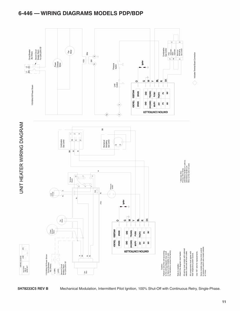
5H78233C5 REV B Mechanical Modulation, Intermittent Pilot Ignition, 100% Shut-Off with Continuous Retry, Single-Phase.
BK
Com
bina
tion
Gas
Con
trol
Mec
hani
cal
Mod
ulat
ing
Gas
Con
trol
D D
BK
W R
1 2
M
3
C P
C
aution
Fa
ilure
to
wire
th
is u
nit a
cco
rdin
g
to t
his
wirin
g d
iag
ram
ma
y r
esu
lt
in in
jury
to
th
e in
sta
ller
or
use
r.
Fo
r d
evia
tio
ns c
on
tact
the
fa
cto
ry.
Pow
er
Exh
aust
Mot
or
V
L2
(W)
L1
(BK
)
115V
/60H
z/1Ø
Pow
er S
how
n
Sec
ond
Circ
uit
Bre
aker
Req
'd.
For
230
V,20
0V,1
Ø
Circ
uit B
reak
er
(B
y O
ther
s)
T1
G
C
Xfm
r
115V
24V
T2
Lim
it
Con
trol
Indi
cate
s Te
rmin
al B
oard
Con
nect
ion
Pre
ssur
e
Sw
itch
Fan
Mot
or
No
te t
o in
sta
ller:
Att
ach
th
is d
iag
ram
ne
ar
he
ate
r.
All
wirin
g m
ust
co
mp
ly w
ith
na
tio
na
l
ele
ctr
ic c
od
e a
nd
all
loca
l co
de
s.
All
co
mp
on
en
ts m
ust
ag
ree
with
the
ir r
esp
ective
po
we
r so
urc
e.
Use
10
5°
wire
fo
r re
pla
ce
me
nts
.
* A
ltern
ate
Xfm
r.
Prim
ary
Xfm
r W
ires
230V
/60H
z/1
Ø-B
K &
Y (
OR
O)
200V
/60H
z/1
Ø-B
K &
R
Wire n
ut th
e w
ire n
ot used.
W
115V
/60H
z/1
Ø P
ow
er
Show
n
C
ircuit B
reaker
(
By O
thers
)
Se
co
nd
Circu
it
Bre
ake
r R
eq
'd
Fo
r 2
30
V,2
00
V,1
Ø
L1
(BK
)
L2
(W)
UN
IT H
EA
TE
R W
IRIN
G D
IAG
RA
MFA
CT
OR
Y
FIE
LD
WIR
E N
UT
24V
.LIN
E
WIR
ING
LE
GE
ND
Fan
Moto
r
* 24V
X
fmr
Term
ina
lB
oa
rd
W BK
BL
BL
BL
GV
F
C
T2
T1
RB
L Lim
it
Contr
ol
BL
Gnd
Pre
ssure
Sw
itch
P
ow
er
Exhaust
M
oto
r
J-B
ox
M DP
Gas
Con
trol
Com
bina
tion
C
Mod
ulat
ing
Mec
hnic
al
Gas
Con
trol
Opera
tor
Main
Opera
tor
Pilo
t
D
BK
RBL
YWGO
Igni
tor
RBL
YWGO
Igni
tor
BK
RBL
YWGO
Igni
tor
RBL
YWGO
Igni
tor
ROBE
RTSH
AWHO
NEYW
ELL
MV
MV
SPA
RK
24V
PV
MV
/PV
24V
(GN
D)
GN
D
TH
(24V
)
PV
SPA
RK
PV
/MV
TR
(GN
D)
GN
D
ROBE
RTSH
AWHO
NEYW
ELL
MV
MV
SPA
RK
24V
PV
MV
/PV
24V
(GN
D)
GN
D
TH
(24V
)
PV
SPA
RK
PV
/MV
TR
(GN
D)
GN
D
ROBE
RTSH
AWHO
NEYW
ELL
MV
MV
SPA
RK
24V
PV
MV
/PV
24V
(GN
D)
GN
D
TH
(24V
)
PV
SPA
RK
PV
/MV
TR
(GN
D)
GN
D
ROBE
RTSH
AWHO
NEYW
ELL
MV
MV
SPA
RK
24V
PV
MV
/PV
24V
(GN
D)
GN
D
TH
(24V
)
PV
SPA
RK
PV
/MV
TR
(GN
D)
GN
D
IGNITION CONTROLLER IGNITION CONTROLLER
IGNITION CONTROLLER IGNITION CONTROLLERS
om
e m
od
els
ma
y h
ave
lim
it c
on
tro
lto
pre
ssu
re s
witch
wire
ro
ute
d o
uts
ide
o
f J-b
ox.
11
12
6-446 — WIRING DIAGRAMS MODELS PDP/BDP
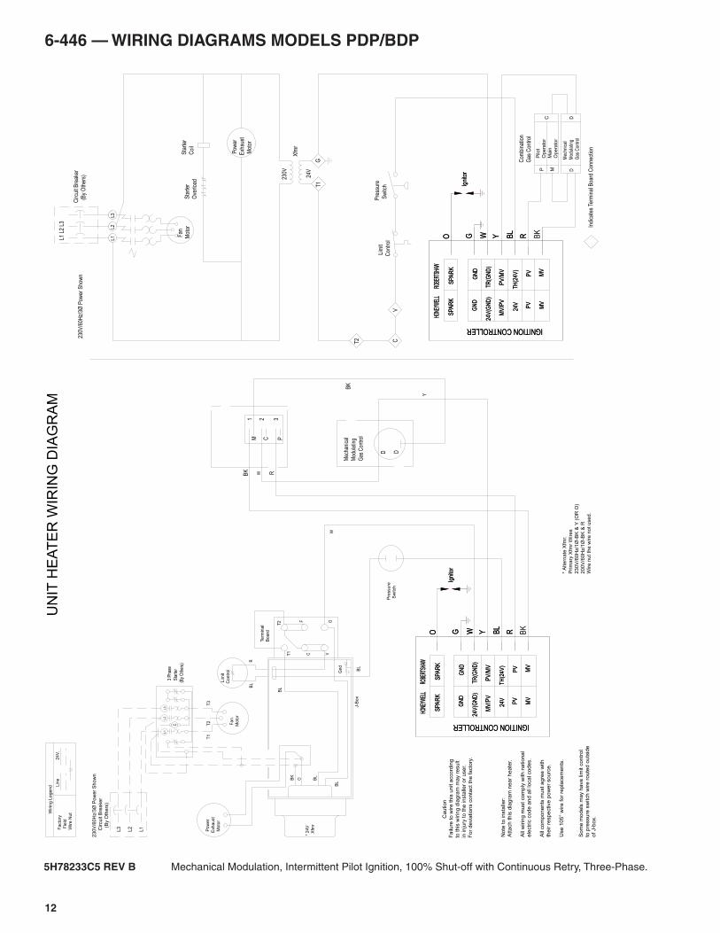
5H78233C5 REV B Mechanical Modulation, Intermittent Pilot Ignition, 100% Shut-off with Continuous Retry, Three-Phase.
W
Fan
Mot
or
L3L2
L1
Circ
uit B
reak
er
(B
y O
ther
s)
L1 L
2 L3
230V
/60H
z/3Ø
Pow
er S
how
n
Sta
rter
Coi
lS
tart
er
Ove
rload
V
T1
G
C
Xfm
r
230V
24V
T2
Lim
it
Con
trol
Indi
cate
s Te
rmin
al B
oard
Con
nect
ion
Pre
ssur
e
Sw
itch
Pow
er
Exh
aust
Mot
or
Mec
hani
cal
Mod
ulat
ing
Gas
Con
trol
D D
PCM
2 31
Y
BK
BK R
No
te t
o in
sta
ller:
Att
ach
th
is d
iag
ram
ne
ar
he
ate
r.
All
wirin
g m
ust
co
mp
ly w
ith
na
tio
na
l
ele
ctr
ic c
od
e a
nd
all
loca
l co
de
s.
All
co
mp
on
en
ts m
ust
ag
ree
with
the
ir r
esp
ective
po
we
r so
urc
e.
Use
10
5°
wire
fo
r re
pla
ce
me
nts
.
C
aution
Fa
ilure
to
wire
th
is u
nit a
cco
rdin
g
to t
his
wirin
g d
iag
ram
ma
y r
esu
lt
in in
jury
to
th
e in
sta
ller
or
use
r.
Fo
r d
evia
tio
ns c
on
tact
the
fa
cto
ry.
* A
ltern
ate
Xfm
r.
Prim
ary
Xfm
r W
ires
230V
/60H
z/1
Ø-B
K &
Y (
OR
O)
200V
/60H
z/1
Ø-B
K &
R
Wire n
ut th
e w
ire n
ot used.
3 P
hase
Sta
rter
(By
Oth
ers)
* 24V
X
fmr
Pre
ssu
re
Sw
itch
W
230V
/60H
z/3Ø
Pow
er
Show
n C
ircu
it B
reake
r
(
By
Oth
ers
)
L1
L2
L3Facto
ry F
ield
Wire N
ut
24V
.Lin
e
Wirin
g L
eg
en
d
C
L3
L2
L1
Fan
Moto
r
T3
T2
T1
BL
J-B
ox
Te
rmin
al
Bo
ard
OBK
BL
BL
BL
GV
F
C
T2
T1
RB
L Lim
it
Co
ntr
ol
Gnd
P
ow
er
Exh
au
st
M
oto
r
UN
IT H
EA
TE
R W
IRIN
G D
IAG
RA
M
CMP
Opera
tor
Main
Opera
tor
Pilo
t
DD
Gas
Con
trol
Mod
ulat
ing
Mec
hnic
al
Gas
Con
trol
Com
bina
tion
BK
RBL
YWGO
Igni
tor
RBL
YWGO
Igni
tor
BK
RBL
YWGO
Igni
tor
RBL
YWGO
Igni
tor
ROBE
RTSH
AWHO
NEYW
ELL
MV
MV
SPA
RK
24V
PV
MV
/PV
24V
(GN
D)
GN
D
TH
(24V
)
PV
SPA
RK
PV
/MV
TR
(GN
D)
GN
D
ROBE
RTSH
AWHO
NEYW
ELL
MV
MV
SPA
RK
24V
PV
MV
/PV
24V
(GN
D)
GN
D
TH
(24V
)
PV
SPA
RK
PV
/MV
TR
(GN
D)
GN
D
ROBE
RTSH
AWHO
NEYW
ELL
MV
MV
SPA
RK
24V
PV
MV
/PV
24V
(GN
D)
GN
D
TH
(24V
)
PV
SPA
RK
PV
/MV
TR
(GN
D)
GN
D
ROBE
RTSH
AWHO
NEYW
ELL
MV
MV
SPA
RK
24V
PV
MV
/PV
24V
(GN
D)
GN
D
TH
(24V
)
PV
SPA
RK
PV
/MV
TR
(GN
D)
GN
D
IGNITION CONTROLLER IGNITION CONTROLLER
IGNITION CONTROLLER IGNITION CONTROLLER
So
me
mo
de
ls m
ay h
ave
lim
it c
on
tro
lto
pre
ssu
re s
witch
wire
ro
ute
d o
uts
ide
o
f J-b
ox.
6-446 — WIRING DIAGRAMS MODELS PDP/BDP
R
W
BK
DM
echa
nica
l
Mod
ulat
ing
Gas
Con
trol
D
Aut
omat
ic
Gas
Con
trol
Aut
omat
ic G
as
Con
trol
Mec
hani
cal
Mod
ulat
ing
Gas
Con
trol
D D
Y
C
aution
Failu
re to w
ire this
unit a
cco
rdin
g
to this
wirin
g d
iagra
m m
ay r
esu
lt
in inju
ry t
o t
he insta
ller
or
user.
For
devia
tions c
onta
ct th
e facto
ry.
Pow
er
Exh
aust
Mot
or
V
L2
(W)
L1
(BK
)
115V
/60H
z/1Ø
Pow
er S
how
n
Sec
ond
Circ
uit
Bre
aker
Req
'd.
For
230
V,20
0V,1
Ø
Circ
uit B
reak
er
(B
y O
ther
s)
T1
G
C
Xfm
r
115V
24V
T2
Lim
it
Con
trol
Indi
cate
s Te
rmin
al B
oard
Con
nect
ion
Pre
ssur
e
Sw
itch
Fan
Mot
or
No
te t
o in
sta
ller:
Att
ach
th
is d
iag
ram
ne
ar
he
ate
r.
All
wirin
g m
ust
co
mp
ly w
ith
na
tio
na
l
ele
ctr
ic c
od
e a
nd
all
loca
l co
de
s.
All
co
mp
on
en
ts m
ust
ag
ree
with
the
ir r
esp
ective
po
we
r so
urc
e.
Use
10
5°
wire
fo
r re
pla
ce
me
nts
.
* A
lte
rna
te X
fmr.
Prim
ary
Xfm
r W
ire
s
23
0V
/60
Hz/1
Ø-B
K &
Y (
OR
O)
20
0V
/60
Hz/1
Ø-B
K &
R
Wire
nu
t th
e w
ire
no
t u
se
d.
W
11
5V
/60H
z/1
Ø P
ow
er
Show
n
C
ircuit B
reaker
(
By O
thers
)
Se
co
nd
Circu
it
Bre
ake
r R
eq
'd
Fo
r 2
30
V,2
00
V,1
Ø
L1
(BK
)
L2
(W)
UN
IT H
EA
TE
R W
IRIN
G D
IAG
RA
MFA
CT
OR
Y
FIE
LD
WIR
E N
UT
24
V.
LIN
E
WIR
ING
LE
GE
ND
Fa
n
Mo
tor
* 2
4V
X
fmr
Te
rmin
al
Bo
ard
W BK
BL
BL
BL
GV
F
C
T2
T1
RB
L Lim
it
Contr
ol
BL
Gn
d
Pre
ssu
re
Sw
itch
P
ow
er
Exhaust
M
oto
r
J-B
ox
RBL
YWGO
Igni
tor
BK
RBL
YWGO
RBL
YWGO
Igni
tor
BK
RBL
YWGO
ROBE
RTSH
AWHO
NEYW
ELL
MV
MV
SPA
RK
24V
PV
MV
/PV
24V
(GN
D)
GN
D
PV
SPA
RK
PV
/MV
TR
(GN
D)
GN
D
ROBE
RTSH
AWHO
NEYW
ELL
MV
MV
SPA
RK
24V
PV
MV
/PV
24V
(GN
D)
GN
D
TH
(24V
)
PV
SPA
RK
PV
/MV
TR
(GN
D)
GN
D
Igni
tor
ROBE
RTSH
AWHO
NEYW
ELL
MV
MV
SPA
RK
24V
PV
MV
/PV
24V
(GN
D)
GN
D
TH
(24V
)
PV
SPA
RK
PV
/MV
TR
(GN
D)
GN
D
ROBE
RTSH
AWHO
NEYW
ELL
MV
MV
SPA
RK
24V
PV
MV
/PV
24V
(GN
D)
GN
D
TH
(24V
)
PV
SPA
RK
PV
/MV
TR
(GN
D)
GN
D
Igni
tor
IGNITION CONTROLLER IGNITION CONTROLLER
IGNITION CONTROLLER IGNITION CONTROLLERS
om
e m
od
els
ma
y h
ave
lim
it c
on
tro
lto
pre
ssu
re s
witch
wire
ro
ute
d o
uts
ide
o
f J-b
ox
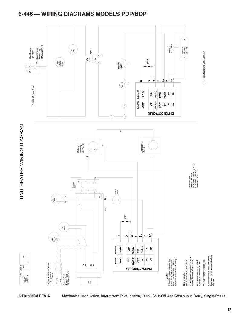
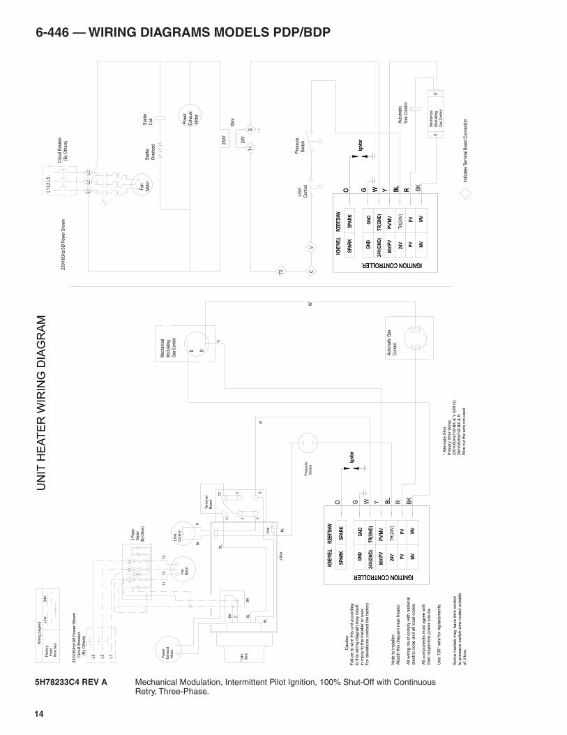
5H78233C4 REV A Mechanical Modulation, Intermittent Pilot Ignition, 100% Shut-Off with Continuous Retry, Single-Phase.
13
14
6-446 — WIRING DIAGRAMS MODELS PDP/BDP
W
Aut
omat
ic
Gas
Con
trol
DM
echa
nica
l
Mod
ulat
ing
Gas
Con
trol
D
Y
Aut
omat
ic G
as
Con
trol
Fan
Mot
or
L3L2
L1
Circ
uit B
reak
er
(B
y O
ther
s)
L1 L
2 L3
230V
/60H
z/3Ø
Pow
er S
how
n
Sta
rter
Coi
lS
tart
er
Ove
rload
V
T1
G
C
Xfm
r
230V
24V
T2
Lim
it
Con
trol
Indi
cate
s Te
rmin
al B
oard
Con
nect
ion
Pre
ssur
e
Sw
itch
Pow
er
Exh
aust
Mot
or
Mec
hani
cal
Mod
ulat
ing
Gas
Con
trol
D D
No
te t
o in
sta
ller:
Att
ach
th
is d
iag
ram
ne
ar
he
ate
r.
All
wirin
g m
ust
co
mp
ly w
ith
na
tio
na
l
ele
ctr
ic c
od
e a
nd
all
loca
l co
de
s.
All
co
mp
on
en
ts m
ust
ag
ree
with
the
ir r
esp
ective
po
we
r so
urc
e.
Use
10
5°
wire
fo
r re
pla
ce
me
nts
.
C
aution
Fa
ilure
to
wire
th
is u
nit a
cco
rdin
g
to t
his
wirin
g d
iag
ram
ma
y r
esu
lt
in in
jury
to
th
e in
sta
ller
or
use
r.
Fo
r d
evia
tio
ns c
on
tact
the
fa
cto
ry.
* A
lte
rna
te X
fmr.
Prim
ary
Xfm
r W
ire
s
23
0V
/60
Hz/1
Ø-B
K &
Y (
OR
O)
20
0V
/60
Hz/1
Ø-B
K &
R
Wire
nu
t th
e w
ire
no
t u
se
d.
3 P
hase
Sta
rter
(By
Oth
ers)
* 2
4V
X
fmr
Pre
ssure
Sw
itch
W
23
0V
/60
Hz/
3Ø
Po
we
r S
ho
wn
C
ircu
it B
rea
ker
(
By
Oth
ers
)
L1
L2
L3
BK
Facto
ry F
ield
Wire N
ut
24
V.
Lin
e
Wirin
g L
egend
C
L3
L2
L1
Fan
Moto
r
T3
T2
T1
BL
J-B
ox
Te
rmin
al
Bo
ard
OBK
BL
BL
BL
GV
F
C
T2
T1
RB
L Lim
it
Co
ntr
ol
Gn
d
P
ow
er
Exh
au
st
M
oto
r
UN
IT H
EA
TE
R W
IRIN
G D
IAG
RA
M
BK
RBL
YWGO
Igni
tor
RBL
YWGO
Igni
tor
RBL
YWGO
Igni
tor
BK
Igni
tor
ROBE
RTSH
AWHO
NEYW
ELL
MV
MV
SPA
RK
24V
PV
MV
/PV
24V
(GN
D)
GN
D
PV
SPA
RK
PV
/MV
TR
(GN
D)
GN
D
ROBE
RTSH
AWHO
NEYW
ELL
MV
MV
SPA
RK
24V
PV
MV
/PV
24V
(GN
D)
GN
D
TH
(24V
)
PV
SPA
RK
PV
/MV
TR
(GN
D)
GN
D
ROBE
RTSH
AWHO
NEYW
ELL
MV
MV
SPA
RK
24V
PV
MV
/PV
24V
(GN
D)
GN
D
PV
SPA
RK
PV
/MV
TR
(GN
D)
GN
D
ROBE
RTSH
AWHO
NEYW
ELL
MV
MV
SPA
RK
24V
PV
MV
/PV
24V
(GN
D)
GN
D
TH
(24V
)
PV
SPA
RK
PV
/MV
TR
(GN
D)
GN
D
IGNITION CONTROLLER IGNITION CONTROLLER
IGNITION CONTROLLER IGNITION CONTROLLER
So
me
mo
de
ls m
ay h
ave
lim
it c
on
tro
lto
pre
ssu
re s
witch
wire
ro
ute
d o
uts
ide
o
f J-b
ox.
5H78233C4 REV A Mechanical Modulation, Intermittent Pilot Ignition, 100% Shut-Off with Continuous Retry, Three-Phase.
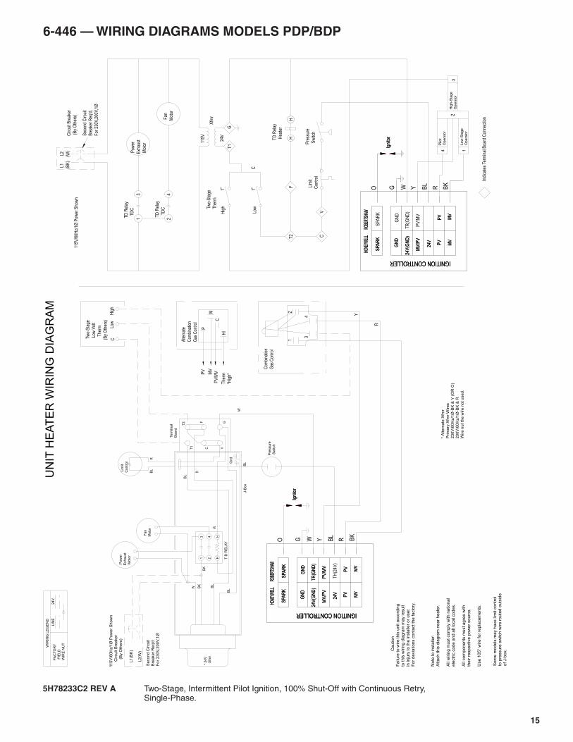
6-446 — WIRING DIAGRAMS MODELS PDP/BDP
15
5H78233C2 REV A Two-Stage, Intermittent Pilot Ignition, 100% Shut-Off with Continuous Retry, Single-Phase.
J-B
ox
P
ow
er
Exh
au
st
M
oto
r
R
24 H
H T-D
RE
LA
Y
Pre
ssure
Sw
itch
Gn
d
BL
Lim
it
Co
ntr
ol
BL
R
T1
T2
C
F
VG
BL
BL
BL
BK
W
W
Te
rmin
al
Bo
ard
* 2
4V
X
fmr
Fan
Moto
r
WIR
ING
LE
GE
ND
LIN
E2
4V
.FA
CT
OR
Y
FIE
LD
WIR
E N
UT
31
BK
UN
IT H
EA
TE
R W
IRIN
G D
IAG
RA
M
L2
(W)
L1(B
K)
Se
co
nd
Circu
it
Bre
ake
r R
eq
'd
For
230V
,200V
,1Ø
115
V/6
0H
z/1
Ø P
ow
er
Sh
ow
n
Circu
it B
rea
ke
r
(
By O
the
rs)
W
* A
lte
rna
te X
fmr
Prim
ary
Xfm
r W
ire
s
23
0V
/60
Hz/1
Ø-B
K &
Y (
OR
O)
20
0V
/60
Hz/1
Ø-B
K &
R
Wire
nu
t th
e w
ire
no
t u
se
d.
No
te t
o in
sta
ller:
Att
ach
th
is d
iag
ram
ne
ar
he
ate
r.
All
wirin
g m
ust
co
mp
ly w
ith
na
tio
na
l
ele
ctr
ic c
od
e a
nd
all
loca
l co
de
s.
All
co
mp
on
en
ts m
ust
ag
ree
with
the
ir r
esp
ective
po
we
r so
urc
e.
Use
10
5°
wire
fo
r re
pla
ce
me
nts
.
TD
Rel
ay
Hea
ter
HH
TD
Rel
ay
TD
C F
an
Mot
or4
2
Pre
ssur
e
Sw
itch
Lim
it
Con
trol
T2
24V
115V
Xfm
r
F
C
GT
1
Two-
Sta
ge
The
rm
t° t°
Hig
h
Low
C
Circ
uit B
reak
er
(B
y O
ther
s)
Sec
ond
Circ
uit
Bre
aker
Req
'd.
For
230
V,20
0V,1
Ø
115V
/60H
z/1Ø
Pow
er S
how
n
L1
(BK
) L
2
(W)
V
1TD
Rel
ay
TD
C
3 P
ower
Exh
aust
Mot
or
43
12
Com
bina
tion
Gas
Con
trol
C
aution
Fa
ilure
to
wire
th
is u
nit a
cco
rdin
g
to t
his
wirin
g d
iag
ram
ma
y r
esu
lt
in in
jury
to
th
e in
sta
ller
or
use
r.
Fo
r d
evia
tio
ns c
on
tact
the
fa
cto
ry.
Tw
o-S
tage
Low
Vol
t
T
herm
(By
Oth
ers)
Low
Hig
hC
R
Y
3O
pera
tor
Hig
h-S
tag
e2
Opera
tor
Low
-Sta
ge
1
Opera
tor
Pilo
t4
Indi
cate
s Te
rmin
al B
oard
Con
nect
ion
ROBE
RTSH
AWHO
NEYW
ELL
MV
MV
SPA
RK
24V
PV
MV
/PV
24V
(GN
D)
GN
D
PV
Igni
tor
BK
ROBE
RTSH
AWHO
NEYW
ELL
MV
MV
SPA
RK
24V
PV
MV
/PV
24V
(GN
D)
GN
D
PV
SPA
RK
PV
/MV
TR
(GN
D)
GN
D
Igni
tor
O G W Y BL
R
ROBE
RTSH
AWHO
NEYW
ELL
MV
MV
SPA
RK
24V
PV
MV
/PV
24V
(GN
D)
GN
D
PV
SPA
RK
PV
/MV
TR
(GN
D)
GN
D
Igni
tor
BK
ROBE
RTSH
AWHO
NEYW
ELL
MV
MV
SPA
RK
24V
PV
MV
/PV
24V
(GN
D)
GN
D
TH
(24V
)
PV
SPA
RK
PV
/MV
TR
(GN
D)
GN
D
Igni
tor
O G W Y BL
R
IGNITION CONTROLLER IGNITION CONTROLLER
IGNITION CONTROLLER IGNITION CONTROLLER
P
M
C
HI
Alte
rnat
e
Com
bina
tion
Gas
Con
trol
PV
MV
PV
/MV
The
rm
"Hig
h"
So
me
mo
de
ls m
ay h
ave
lim
it c
on
tro
lto
pre
ssu
re s
witch
wire
ro
ute
d o
uts
ide
o
f J-b
ox.
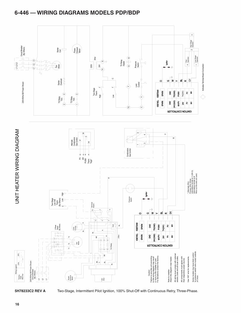
6-446 — WIRING DIAGRAMS MODELS PDP/BDP
16
5H78233C2 REV A Two-Stage, Intermittent Pilot Ignition, 100% Shut-Off with Continuous Retry, Three-Phase.
UN
IT H
EA
TE
R W
IRIN
G D
IAG
RA
M
P
ow
er
Exh
au
st
M
oto
r
24 H
H T-D
Rela
y
31
R
Gn
d
Lim
it
Co
ntr
ol
BL
R
T1
T2
C
F
VG
BL
BL
BL
BK
O
W
Te
rmin
al
Bo
ard
J-B
ox
BL
T1
T2
T3
Fan
Moto
r
L1
L2
L3
C
Wirin
g L
egend L
ine
24
V.
Facto
ry
Fie
ld
Wire N
ut
BK
BR
L3
L2
L1
23
0V
/60
Hz/
3Ø
Po
we
r S
ho
wn
C
ircu
it B
rea
ker
(
By
Oth
ers
)
W
TD
Rel
ay
L3L2
L1
Circ
uit B
r eak
er
(B
y O
ther
s)
L1 L
2 L3
Sta
rter
Coi
lS
tart
er
Ove
rload
42
TD
C
Indi
cate
s Te
rmin
al B
oard
Con
nect
ion
Fan
Mot
or
230V
/60H
z/3Ø
Pow
er S
how
n
TD
Rel
ay
Hea
ter
HH
Lim
it
Con
trol
T2
F
C
Two-
Sta
ge
The
rm
t° t°
Hig
h
Low
C
T1
G
Xfm
r
230V
24V
V
Pre
ssure
Sw
itch
Com
bina
tion
Gas
Con
trol
21
43
* 2
4V
X
fmr
3 P
hase
Sta
rter
(By
Oth
ers)
* A
lte
rna
te X
fmr.
Prim
ary
Xfm
r W
ire
s
23
0V
/60
Hz/1
Ø-B
K &
Y (
OR
O)
20
0V
/60
Hz/1
Ø-B
K &
R
Wire
nu
t th
e w
ire
no
t u
se
d.
C
aution
Fa
ilure
to
wire
th
is u
nit a
cco
rdin
g
to t
his
wirin
g d
iag
ram
ma
y r
esu
lt
in in
jury
to
th
e in
sta
ller
or
use
r.
Fo
r d
evia
tio
ns c
on
tact
the
fa
cto
ry.
No
te t
o in
sta
ller:
Att
ach
th
is d
iag
ram
ne
ar
he
ate
r.
All
wirin
g m
ust
co
mp
ly w
ith
na
tio
na
l
ele
ctr
ic c
od
e a
nd
all
loca
l co
de
s.
All
co
mp
on
en
ts m
ust
ag
ree
with
the
ir r
esp
ective
po
we
r so
urc
e.
Use
10
5°
wire
fo
r re
pla
ce
me
nts
.
Tw
o-S
tage
Low
Vol
t
T
herm
(By
Oth
ers)
Low
Hig
hC
13
Pow
er
Exh
aust
Mot
or
Y
R
TD
Rel
ayT
DC
4P
ilot
Opera
tor
1Low
-Sta
ge
Opera
tor
2H
igh
-Sta
ge
Opera
tor
3
Pre
ssur
e
Sw
itch
RBL
YWGO
Igni
tor
GY
RBL
YWGO
Igni
tor
RBL
YWGO
Igni
tor
BK
RBL
YWGO
ROBE
RTSH
AWHO
NEYW
ELL
MV
MV
SPA
RK
24V
PV
MV
/PV
24V
(GN
D)
GN
D
PV
SPA
RK
PV
/MV
TR
(GN
D)
GN
D
ROBE
RTSH
AWHO
NEYW
ELL
MV
MV
SPA
RK
24V
PV
MV
/PV
24V
(GN
D)
GN
D
TH
(24V
)
PV
SPA
RK
PV
/MV
TR
(GN
D)
GN
D
ROBE
RTSH
AWHO
NEYW
ELL
MV
MV
SPA
RK
24V
PV
MV
/PV
24V
(GN
D)
GN
D
TH
(24V
)
PV
SPA
RK
PV
/MV
TR
(GN
D)
GN
D
ROBE
RTSH
AWHO
NEYW
ELL
MV
MV
SPA
RK
24V
PV
MV
/PV
24V
(GN
D)
GN
D
TH
(24V
)
PV
SPA
RK
PV
/MV
TR
(GN
D)
GN
D
Igni
tor
IGNITION CONTROLLER IGNITION CONTROLLER
IGNITION CONTROLLER IGNITION CONTROLLER
P
M
C
HI
Alte
rnat
e
Com
bina
tion
Gas
Con
trol
PV
MV
PV
/MV
The
rm
"Hig
h"
So
me
mo
de
ls m
ay h
ave
lim
it c
on
tro
lto
pre
ssu
re s
witch
wire
ro
ute
d o
uts
ide
o
f J-b
ox.
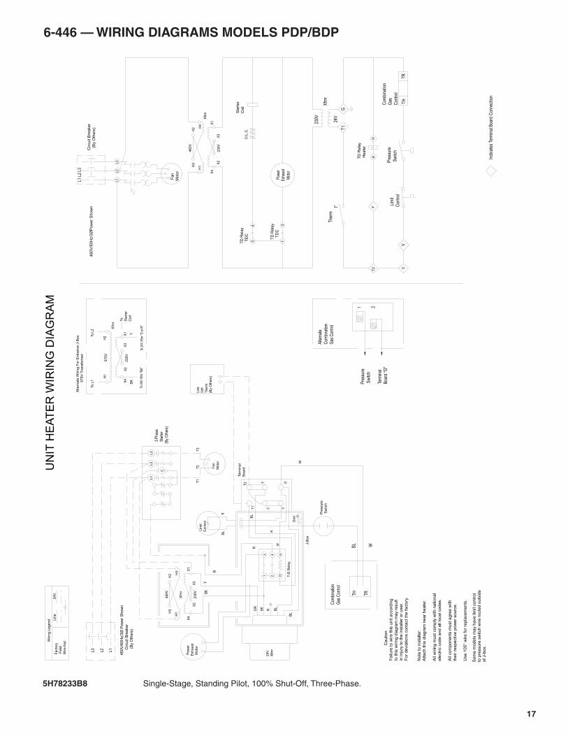
17
6-446 — WIRING DIAGRAMS MODELS PDP/BDP
5H78233B8 Single-Stage, Standing Pilot, 100% Shut-Off, Three-Phase.
TD
Re
lay
T
DC
TD
Re
lay
T
DC
Com
bina
tion
Gas
Con
trol
TR
TH
Pre
ssur
e
Sw
itch
Lim
it
Con
trol
V
Alte
rnat
e
Com
bina
tion
Gas
Con
trol
21
Term
inal
Boa
rd "
G"
Pre
ssur
e
Sw
itch
W
Pre
ssure
Sw
itch
WBL
TRTH
Com
bina
tion
Gas
Con
trol
UN
IT H
EA
TE
R W
IRIN
G D
IAG
RA
MW
iri n
g L
egend L
ine
24
V.
Facto
ry
Fie
ld
Wire N
ut
C
aution
Fa
ilure
to
wire
th
is u
nit a
cco
rdin
g
to t
his
wirin
g d
iag
ram
ma
y r
esu
lt
in in
jury
to
th
e in
sta
ller
or
use
r.
Fo
r d
evia
tio
ns c
on
tact
the
fa
cto
ry.
No
te t
o in
sta
ller:
Att
ach
th
is d
iag
ram
ne
ar
he
ate
r.
All
wirin
g m
ust
co
mp
ly w
ith
na
tio
na
l
ele
ctr
ic c
od
e a
nd
all
loca
l co
de
s.
All
co
mp
on
en
ts m
ust
ag
ree
with
the
ir r
esp
ective
po
we
r so
urc
e.
Use
10
5°
wire
fo
r re
pla
ce
me
nts
.
Indi
cate
s Te
rmin
al B
oard
Con
nect
ion
31
O.L
.C.
24
T2
F
C
Xfm
r
H1
H2
H3
H4 X
1
X2
X3
X4
46
0V
23
0V
460V
/60H
z/3
ØP
ow
er
Show
n
Fan
Moto
r
L1
L2
L3
Circu
it B
rea
ke
r
(B
y O
the
rs)
L1L2
L3
Sta
rte
r
Co
il
HH
TD
Re
lay
He
ate
r
The
rmt°
230V
Xfm
r
24V
T1
G
Pow
er E
xhau
st M
oto r
Po
we
r
Exh
au
st
Mo
tor
24 H
H T-D
Re
lay
31
R
Gn
d
Lim
it
Co
ntr
ol
BL
R
T1
T2
C
F
VG
BL
W
Te
rmin
al
Bo
ard
24V
Xfm
r
J-B
ox
BL
Low
Volt
Therm
(By
Oth
ers
)
R
T1
T2
T3
Fan
Moto
r
L1
L2
L3
C
OR
BK
Xfm
r
H1
H2
H3
H4 X
1
X2
X3
X4
46
0V
23
0V
46
0V
/60
Hz/
3Ø
Po
we
r S
ho
wn
C
ircu
it B
rea
ker
(B
y O
thers
)
L2
L1
L3
BK
Y
R
3 P
hase
Sta
rter
(By
Oth
ers)
Xfm
r
H1
H2To
L2
X2
X3
To L
1
57
5V
23
0V
Altern
ate
Wirin
g F
or
Entr
ance J
-Box
575V
Tra
nsfo
rmer
To 2
4V X
fmr "
BK
"To
24V
Xfm
r "O
or R
"
BK
Y
To Sta
rte
r
Co
il
R BL
X4
X1
So
me
mo
de
ls m
ay h
ave
lim
it c
on
tro
lto
pre
ssu
re s
witch
wire
ro
ute
d o
uts
ide
o
f J-b
ox.
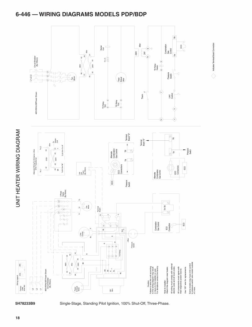
18
6-446 — WIRING DIAGRAMS MODELS PDP/BDP
5H78233B9 Single-Stage, Standing Pilot Ignition, 100% Shut-Off, Three-Phase.
TD
Re
lay
T
DC
TD
Re
lay
T
DC
EC
O
TR
Com
bina
tion
Gas
Con
trol
TH
Pre
ssur
e
Sw
itch
Lim
it
Con
trol
V
Pre
ssure
Sw
itch
UN
IT H
EA
TE
R W
IRIN
G D
IAG
RA
MW
iri n
g L
egend L
ine
24
V.
Facto
ry
Fie
ld
Wire N
ut
C
aution
Fa
ilure
to
wire
th
is u
nit a
cco
rdin
g
to t
his
wirin
g d
iag
ram
ma
y r
esu
lt
in in
jury
to
th
e in
sta
ller
or
use
r.
Fo
r d
evia
tio
ns c
on
tact
the
fa
cto
ry.
No
te t
o in
sta
ller:
Att
ach
th
is d
iag
ram
ne
ar
he
ate
r.
All
wirin
g m
ust
co
mp
ly w
ith
na
tio
na
l
ele
ctr
ic c
od
e a
nd
all
loca
l co
de
s.
All
co
mp
on
en
ts m
ust
ag
ree
with
the
ir r
esp
ective
po
we
r so
urc
e.
Use
10
5°
wire
fo
r re
pla
ce
me
nts
.
Indi
cate
s Te
rmin
al B
oard
Con
nect
ion
31
O.L
.C.
24
T2
F
C
Xfm
r
H1
H2
H3
H4 X
1
X2
X3
X4
46
0V
23
0V
460V
/60H
z/3
ØP
ow
er
Show
n
Fan
Mo
tor
L1
L2
L3
Circu
it B
rea
ke
r
(B
y O
the
rs)
L1L2
L3
Sta
rte
r
Co
il
HH
TD
Re
lay
He
ate
r
The
rmt°
230V
Xfm
r
24V
T1
G
Pow
er
Exh
aust
Mot
or
Po
we
r
Exh
au
st
Mo
tor
24 H
H T-D
Rela
y
31
R
Gn
d
Lim
it
Co
ntr
ol
BL
R
T1
T2
C
F
VG
BL
W
Te
rmin
al
Bo
ard
24V
Xfm
r
J-B
ox
BL
Low
Volt
Therm
(By
Oth
ers
)
R
T1
T2
T3
Fan
Moto
r
L1
L2
L3
C
OR
BK
Xfm
r
H1
H2
H3
H4 X
1
X2
X3
X4
46
0V
23
0V
46
0V
/60
Hz/
3Ø
Po
we
r S
ho
wn
C
ircu
it B
rea
ker
(
By
Oth
ers
)
L2
L1
L3
BK
Y
R
3 P
hase
Sta
rter
(By
Oth
ers)
Xfm
r
H1
H2To
L2
X2
X3
To L
1
57
5V
23
0V
Altern
ate
Wirin
g F
or
Entr
ance J
-Box
575V
Tra
nsfo
rmer
To 2
4V X
fmr "
BK
"To
24V
Xfm
r "O
or R
"
BK
Y
To Sta
rte
r
Co
il
R BL
X4
X1
EC
O
Con
nect
ion
E
CO
TH T
R
Gas
Con
trol
Com
bina
tion
Gas
Con
trol
Com
bina
tion
Alte
rnat
e
TRTH
Sw
itch
Pre
ssur
e
Con
nect
ions
EC
O
EC
O
Term
inal
Boa
rd "G
"
Con
nect
ions
EC
O
Boa
rd "
G"
Term
inal
Sw
itch
Pre
ssur
e
Gas
Con
trol
Com
bina
tion
Alte
rnat
eE
CO
TR
TH
So
me
mo
de
ls m
ay h
ave
lim
it c
on
tro
lto
pre
ssu
re s
witch
wire
ro
ute
d o
uts
ide
o
f J-b
ox.
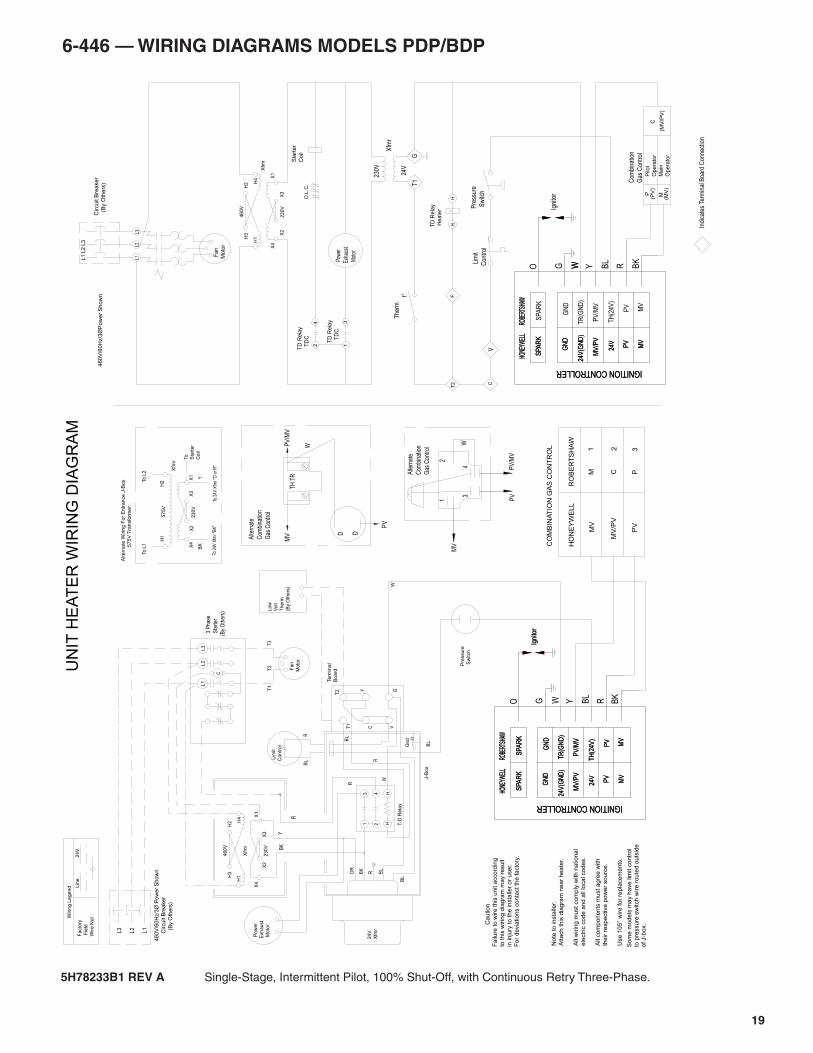
19
6-446 — WIRING DIAGRAMS MODELS PDP/BDP
W
C
MP
Op
era
tor
Ma
in
Op
era
tor
Pilo
t
Gas
Con
trol
Com
bina
tion
TD
Re
lay
T
DC
TD
Re
lay
T
DC
UN
IT H
EA
TE
R W
IRIN
G D
IAG
RA
M
BL
Wiri n
g L
egend L
ine
24
V.
Facto
ry
Fie
ld
Wire N
ut
W
Pre
ssure
Sw
itch
C
aution
Fa
ilure
to
wire
th
is u
nit a
cco
rdin
g
to t
his
wirin
g d
iag
ram
ma
y r
esu
lt
in in
jury
to
th
e in
sta
ller
or
use
r.
Fo
r d
evia
tio
ns c
on
tact
the
fa
cto
ry.
No
te t
o in
sta
ller:
Att
ach
th
is d
iag
ram
ne
ar
he
ate
r.
All
wirin
g m
ust
co
mp
ly w
ith
na
tio
na
l
ele
ctr
ic c
od
e a
nd
all
loca
l co
de
s.
All
co
mp
on
en
ts m
ust
ag
ree
with
the
ir r
esp
ective
po
we
r so
urc
e.
Use
10
5°
wire
fo
r re
pla
ce
me
nts
.
Indi
cate
s Te
rmin
al B
oard
Con
nect
ion
31
O.L
.C.
24
T2
F
C
Xfm
r
H1
H2
H3
H4 X
1
X2
X3
X4
46
0V
23
0V
460V
/60H
z/3
ØP
ow
er
Show
n
Fan
Moto
r
L1
L2
L3
Circu
it B
rea
ke
r
(B
y O
the
rs)
L1L2
L3
Sta
rte
r
Co
il
HH
TD
Re
lay
He
ate
r
V
Lim
it
Con
trol
Pre
ssur
e
Sw
itch
The
rmt°
230V
Xfm
r
24V
T1
G
Pow
er
Exh
aust
Mot
or
Po
we
r
Exh
au
st
Mo
tor
24 H
H T-D
Rela
y
31
R
Gn
d
Lim
it
Co
ntr
ol
BL
R
T1
T2
C
F
VG
BL
W
Te
rmin
al
Bo
ard
24V
Xfm
r
J-B
ox
BL
R
T1
T2
T3
Fan
Moto
r
L1
L2
L3
C
OR
BK
Xfm
r
H1
H2
H3
H4 X
1
X2
X3
X4
46
0V
23
0V
46
0V
/60
Hz/
3Ø
Po
we
r S
ho
wn
C
ircu
it B
rea
ker
(
By
Oth
ers
)
L2
L1
L3
BK
Y
R
3 P
hase
Sta
rter
(By
Oth
ers)
Xfm
r
H1
H2To
L2
X2
X3
To L
1
57
5V
23
0V
Altern
ate
Wirin
g F
or
Entr
ance J
-Box
575V
Tra
nsfo
rmer
To 2
4V X
fmr "
BK
"To
24V
Xfm
r "O
or R
"
BK
Y
To Sta
rte
r
Co
il
R BL
X4
X1
MV
PV
/MV
PV
Gas
Con
trol
Com
bina
tion
Alte
rnat
e
43
12
(By
Oth
ers
)
Therm
Volt
Low
D D
TH T
R
W
Alte
rnat
e
Com
bina
tion
Gas
Con
trol
MV
PV
PV
/MV
ROBE
RTSH
AWHO
NEYW
ELL
MV
MV
SPA
RK
24V
PV
MV
/PV
24V
(GN
D)
GN
D
TH
(24V
)
PV
SPA
RK
PV
/MV
TR
(GN
D)
GN
D
Igni
tor
ROBE
RTSH
AWHO
NEYW
ELL
MV
MV
SPA
RK
24V
PV
MV
/PV
24V
(GN
D)
GN
D
TH
(24V
)
PV
SPA
RK
PV
/MV
TR
(GN
D)
GN
D
Igni
tor
O G W Y BL
R BK
ROBE
RTSH
AWHO
NEYW
ELL
MV
SPA
RK
24V
PV
MV
/PV
24V
(GN
D)
GN
D
W BK
ROBE
RTSH
AWHO
NEYW
ELL
MV
MV
SPA
RK
24V
PV
MV
/PV
24V
(GN
D)
GN
D
TH
(24V
)
PV
SPA
RK
PV
/MV
TR
(GN
D)
GN
D
Igni
tor
O G W Y BL
R
IGNITION CONTROLLER IGNITION CONTROLLER
IGNITION CONTROLLER IGNITION CONTROLLER
So
me
mo
de
ls m
ay h
ave
lim
it c
on
tro
lto
pre
ssu
re s
witch
wire
ro
ute
d o
uts
ide
o
f J-b
ox.
CO
MB
INA
TIO
N G
AS
CO
NT
RO
L
MV
/PV
MV
HO
NE
YW
EL
LR
OB
ER
TS
HA
W
M1
C2
P3
PV
(MV
/PV
)(M
V)
(PV
)
5H78233B1 REV A Single-Stage, Intermittent Pilot, 100% Shut-Off, with Continuous Retry Three-Phase.
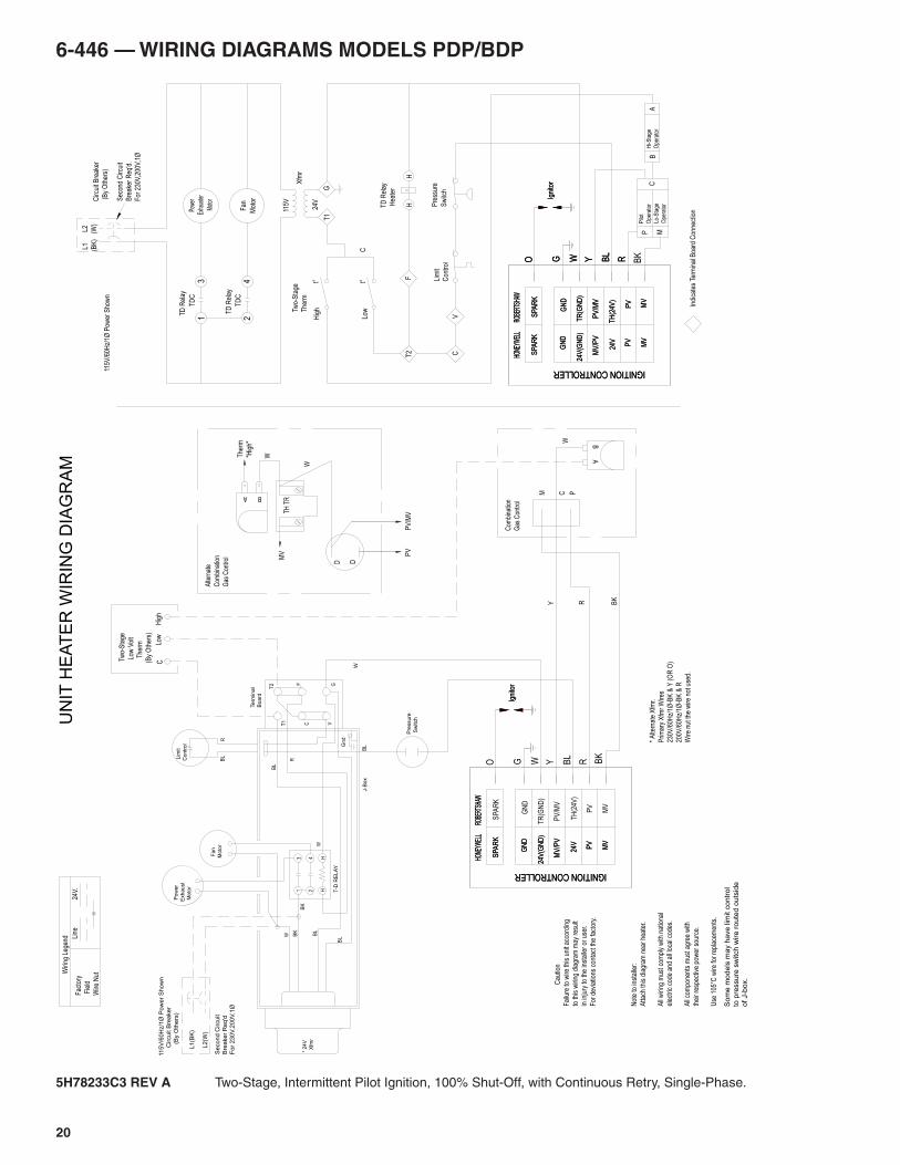
20
6-446 — WIRING DIAGRAMS MODELS PDP/BDP
5H78233C3 REV A Two-Stage, Intermittent Pilot Ignition, 100% Shut-Off, with Continuous Retry, Single-Phase.
J-B
ox
P
ow
er
Exh
au
st
M
oto
r
R
24 H
H T-D
RE
LA
Y
Gnd
BL
Lim
it
Co
ntr
ol
BL
R
T1
T2
C
F
VG
BL
BL
BL
BK
W
W
Te
rmin
al
Bo
ard
* 24V
X
fmr
Fan
Moto
r
31
BK
L2
(W)
L1
(BK
)
Se
co
nd
Circu
it
Bre
ake
r R
eq
'd
Fo
r 2
30
V,2
00
V,1
Ø
11
5V
/60
Hz/1
Ø P
ow
er
Sh
ow
n
Circu
it B
rea
ke
r
(
By O
the
rs)
W
Tw
o-S
tage
Low
Vol
t
T
herm
(By
Oth
ers)
Low
Hig
hC
Fan
Mot
or
TD
C
24
TD
Rel
ay
TD
Rel
ay
Pow
erEx
haus
ter
Mot
or3
1T
DC
RBL
YWGO
Igni
tor
BK
RBL
YWGO
Igni
tor
BKRBL
YWGO
ROBE
RTSH
AWHO
NEYW
ELL
MV
SPA
RK
24V
PV
MV
/PV
24V
(GN
D)
GN
D
ROBE
RTSH
AWHO
NEYW
ELL
MV
MV
SPA
RK
24V
PV
MV
/PV
24V
(GN
D)
GN
D
TH
(24V
)
PV
SPA
RK
PV
/MV
TR
(GN
D)
GN
D
Igni
tor
ROBE
RTSH
AWHO
NEYW
ELL
MV
MV
SPA
RK
24V
PV
MV
/PV
24V
(GN
D)
GN
D
TH
(24V
)
PV
SPA
RK
PV
/MV
TR
(GN
D)
GN
D
ROBE
RTSH
AWHO
NEYW
ELL
MV
MV
SPA
RK
24V
PV
MV
/PV
24V
(GN
D)
GN
D
TH
(24V
)
PV
SPA
RK
PV
/MV
TR
(GN
D)
GN
D
Igni
tor
IGNITION CONTROLLER IGNITION CONTROLLER
IGNITION CONTROLLER IGNITION CONTROLLER
Wiri
ng L
egen
d Line
24V.
Fac
tory
Fie
ld
Wire
Nut
* A
ltern
ate
Xfm
r.
Prim
ary
Xfm
r W
ires
230V
/60H
z/1Ø
-BK
& Y
(O
R O
)
200V
/60H
z/1Ø
-BK
& R
Wire
nut
the
wire
not
use
d.
Cau
tion
Fai
lure
to w
ire th
is u
nit a
ccor
ding
to th
is w
iring
dia
gram
may
res
ult
in in
jury
to th
e in
stal
ler
or u
ser.
For
dev
iatio
ns c
onta
ct th
e fa
ctor
y.
Not
e to
inst
alle
r:
Atta
ch th
is d
iagr
am n
ear
heat
er.
All
wiri
ng m
ust c
ompl
y w
ith n
atio
nal
elec
tric
cod
e an
d al
l loc
al c
odes
.
All
com
pone
nts
mus
t agr
ee w
ith
thei
r re
spec
tive
pow
er s
ourc
e.
Use
105
°C w
ire fo
r re
plac
emen
ts.
TD
Rel
ay
Hea
ter
HH
UN
IT H
EA
TE
R W
IRIN
G D
IAG
RA
M
Pre
ssur
e
Sw
itch
Indi
cate
s Te
rmin
al B
oard
Con
nect
ion
Lim
it
Con
trol
T2
24V
115V
Xfm
r
F
C
GT
1
Two-
Sta
ge
The
rm
t° t°
Hig
h
Low
C
R BK
Y
Circ
uit B
reak
er
(B
y O
ther
s)
Sec
ond
Circ
uit
Bre
aker
Req
'd.
For
230
V,20
0V,1
Ø
115V
/60H
z/1Ø
Pow
er S
how
n
L1
(BK
)
L2
(W)
M C P
ABW
Com
bina
tion
Gas
Con
trol
BA
D D
TH T
R
W
W
Alte
rnat
e
Com
bina
tion
Gas
Con
trol M
V PV
PV
/MV
The
rm
"Hig
h"
V
P
Ope
rato
r
Lo-S
tage
Ope
rato
r
Pilo
t
CM
BH
i-Sta
ge
Ope
rato
rA
Som
e m
odels
may h
ave lim
it c
ontr
ol
to p
ressu
re s
witch
wire
ro
ute
d o
uts
ide
of J-b
ox.
Sw
itch
Pre
ssure
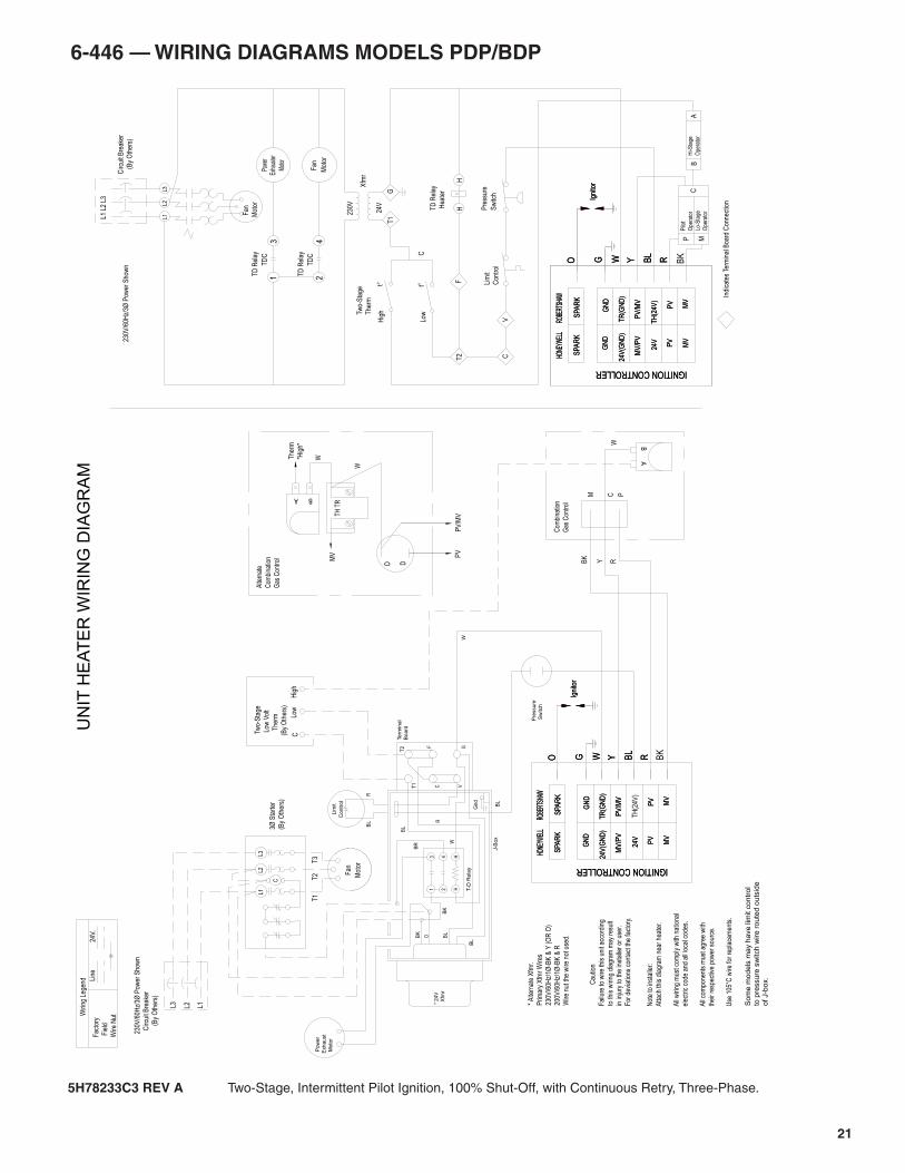
21
6-446 — WIRING DIAGRAMS MODELS PDP/BDP
5H78233C3 REV A Two-Stage, Intermittent Pilot Ignition, 100% Shut-Off, with Continuous Retry, Three-Phase.
CH
igh
Low
(By
Oth
ers)
T
herm
Low
Vol
t
Tw
o-S
tage
X
fmr
* 24V
Sw
itch
Pre
ssu
re
W
BR
BK
BL
J-B
ox
Bo
ard
Te
rmin
al
W
OBK
BL
BL
BL
GV
F
C
T2
T1
RB
L
Co
ntr
ol
Lim
it
Gn
d
R
13
T-D
Rela
y
HH4
2
M
oto
r
Exh
au
st
P
ow
er
Fan
Mot
or
TD
C
24
TD
Rel
ay
TD
Rel
ay
Pow
erEx
haus
ter
Mot
or3
1T
DC
RBL
YWGO
Igni
tor
BKRBL
YWGO
RBL
YWGO
Igni
tor
BK
RBL
YWGO
Igni
tor
ROBE
RTSH
AWHO
NEYW
ELL
MV
MV
SPA
RK
24V
PV
MV
/PV
24V
(GN
D)
GN
D
TH
(24V
)
PV
SPA
RK
PV
/MV
TR
(GN
D)
GN
D
ROBE
RTSH
AWHO
NEYW
ELL
MV
MV
SPA
RK
24V
PV
MV
/PV
24V
(GN
D)
GN
D
TH
(24V
)
PV
SPA
RK
PV
/MV
TR
(GN
D)
GN
D
Igni
tor
ROBE
RTSH
AWHO
NEYW
ELL
MV
MV
SPA
RK
24V
PV
MV
/PV
24V
(GN
D)
GN
D
PV
SPA
RK
PV
/MV
TR
(GN
D)
GN
D
ROBE
RTSH
AWHO
NEYW
ELL
MV
MV
SPA
RK
24V
PV
MV
/PV
24V
(GN
D)
GN
D
TH
(24V
)
PV
SPA
RK
PV
/MV
TR
(GN
D)
GN
D
IGNITION CONTROLLER IGNITION CONTROLLER
IGNITION CONTROLLER IGNITION CONTROLLER
V
24V
230V
Xfm
r
GT
1
* A
ltern
ate
Xfm
r.
Prim
ary
Xfm
r W
ires
230V
/60H
z/1Ø
-BK
& Y
(O
R O
)
200V
/60H
z/1Ø
-BK
& R
Wire
nut
the
wire
not
use
d.
Not
e to
inst
alle
r:
Atta
ch th
is d
iagr
am n
ear
heat
er.
All
wiri
ng m
ust c
ompl
y w
ith n
atio
nal
elec
tric
cod
e an
d al
l loc
al c
odes
.
All
com
pone
nts
mus
t agr
ee w
ith
thei
r re
spec
tive
pow
er s
ourc
e.
Use
105
°C w
ire fo
r re
plac
emen
ts.
Cau
tion
Fai
lure
to w
ire th
is u
nit a
ccor
ding
to th
is w
iring
dia
gram
may
res
ult
in in
jury
to th
e in
stal
ler
or u
ser.
For
dev
iatio
ns c
onta
ct th
e fa
ctor
y.
Wiri
ng L
egen
d Line
24V.
Fac
tory
Fie
ld
Wire
Nut
L3L2
L1
Circ
uit B
reak
er
(
By
Oth
ers)
L1 L
2 L3
UN
IT H
EA
TE
R W
IRIN
G D
IAG
RA
M
Indi
cate
s Te
rmin
al B
oard
Con
nect
ion
Fan
Mot
or
230V
/60H
z/3Ø
Pow
er S
how
n
BK
Y R
TD
Rel
ay
Hea
ter
HH P
ress
ure
Sw
itch
Lim
it
Con
trol
T2
F
C
Two-
Sta
ge
The
rm
t° t°
Hig
h
Low
C
The
rm
"Hig
h"
PV
/MV
PV
MV
Alte
rnat
e
Com
bina
tion
Gas
Con
trol
W
W
TH T
R
DD
A B
Com
bina
tion
Gas
Con
trol
W BA
PCM
Hi-S
tage
Ope
rato
rLo
-Sta
ge
Ope
rato
rMP
A
Pilo
t
Ope
rato
rB
C
C
L3L2
L1
230V
/60H
z/3Ø
Pow
er S
how
n
Circ
uit B
reak
er
(
By
Oth
ers)
L3 L2 L1
T1
T2
T3
Fan
Mot
or
3Ø S
tart
er
(By
Oth
ers)
So
me
mo
de
ls m
ay h
ave
lim
it c
on
tro
lto
pre
ssu
re s
witch
wire
ro
ute
d o
uts
ide
o
f J-b
ox.
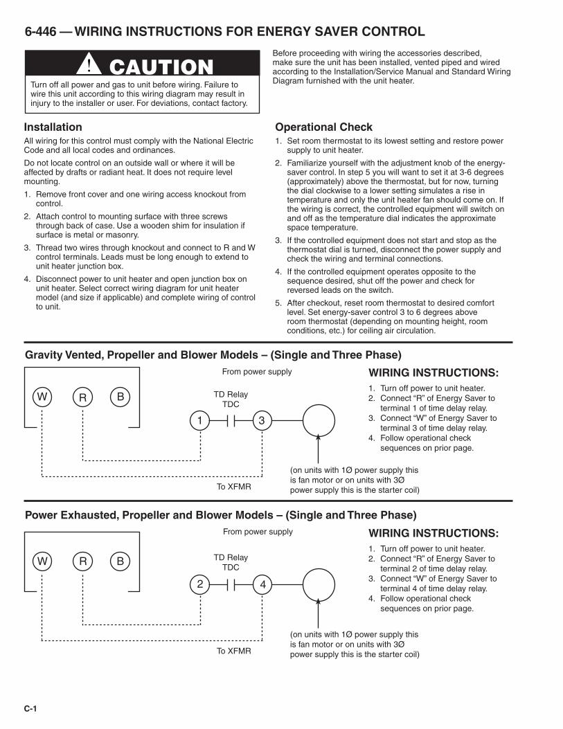
C-1
InstallationAll wiring for this control must comply with the National Electric Code and all local codes and ordinances.
Do not locate control on an outside wall or where it will be affected by drafts or radiant heat. It does not require level mounting.
1. Remove front cover and one wiring access knockout from control.
2. Attach control to mounting surface with three screws through back of case. Use a wooden shim for insulation if surface is metal or masonry.
3. Thread two wires through knockout and connect to R and W control terminals. Leads must be long enough to extend to unit heater junction box.
4. Disconnect power to unit heater and open junction box on unit heater. Select correct wiring diagram for unit heater model (and size if applicable) and complete wiring of control to unit.
Operational Check1. Set room thermostat to its lowest setting and restore power
supply to unit heater.
2. Familiarize yourself with the adjustment knob of the energy-saver control. In step 5 you will want to set it at 3-6 degrees (approximately) above the thermostat, but for now, turning the dial clockwise to a lower setting simulates a rise in temperature and only the unit heater fan should come on. If the wiring is correct, the controlled equipment will switch on and off as the temperature dial indicates the approximate space temperature.
3. If the controlled equipment does not start and stop as the thermostat dial is turned, disconnect the power supply and check the wiring and terminal connections.
4. If the controlled equipment operates opposite to the sequence desired, shut off the power and check for reversed leads on the switch.
5. After checkout, reset room thermostat to desired comfort level. Set energy-saver control 3 to 6 degrees above room thermostat (depending on mounting height, room conditions, etc.) for ceiling air circulation.
6-446 — WIRING INSTRUCTIONS FOR ENERGY SAVER CONTROL
W R B
WIRING INSTRUCTIONS:1. Turn off power to unit heater.2. Connect “R” of Energy Saver to
terminal 1 of time delay relay.3. Connect “W” of Energy Saver to
terminal 3 of time delay relay.4. Follow operational check
sequences on prior page.
WIRING INSTRUCTIONS:1. Turn off power to unit heater.2. Connect “R” of Energy Saver to
terminal 2 of time delay relay.3. Connect “W” of Energy Saver to
terminal 4 of time delay relay.4. Follow operational check
sequences on prior page.
1
(on units with 1Ø power supply this is fan motor or on units with 3Ø power supply this is the starter coil)
TD RelayTDC
To XFMR
From power supply
From power supply
Gravity Vented, Propeller and Blower Models – (Single and Three Phase)
W R B
2 4
(on units with 1Ø power supply this is fan motor or on units with 3Ø power supply this is the starter coil)
TD RelayTDC
To XFMR
Power Exhausted, Propeller and Blower Models – (Single and Three Phase)
3
Before proceeding with wiring the accessories described, make sure the unit has been installed, vented piped and wired according to the Installation/Service Manual and Standard Wiring Diagram furnished with the unit heater.
CAUTIONTurn off all power and gas to unit before wiring. Failure to wire this unit according to this wiring diagram may result in injury to the installer or user. For deviations, contact factory.
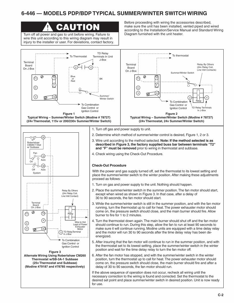
C-2
6-446 — MODELS PDP/BDP TYPICAL SUMMER/WINTER SWITCH WIRING
Before proceeding with wiring the accessories described, make sure the unit has been installed, vented piped and wired according to the Installation/Service Manual and Standard Wiring Diagram furnished with the unit heater.
CAUTIONTurn off all power and gas to unit before wiring. Failure to wire this unit according to this wiring diagram may result in injury to the installer or user. For deviations, contact factory.
1. Turn off gas and power supply to unit.
2. Determine which method of summer/winter control is desired, Figure 1, 2 or 3.
3. Wire unit according to the method selected. Note: If the method selected is as described in Figure 3, the factory supplied buss bar between terminals "T2" and "F" must be removed prior to wiring in thermostat and subbase.
4. Check wiring using the Check-Out Procedure.
Check-Out Procedure
With the power and gas supply turned off, set the thermostat to its lowest setting and place the summer/winter switch to the winter position. After making these adjustments proceed as follows:
1. Turn on gas and power supply to the unit. Nothing should happen.
2. Place the summer/winter switch in the summer position. The fan motor should start, except when wired as shown in Figure 3. In that case, after a delay of 30 to 90 seconds, the fan motor should start.
3. While the summer/winter switch is still in the summer position, and with the fan motor running, turn the thermostat up to call for heat. The power exhauster motor should come on, the pressure switch should close, and the main burner should fire. Allow burner to fire for 1 to 2 minutes.
4. Turn the thermostat down again. The main burner should shut off and the fan motor should continue to run. During this step, allow the fan to run at least 90 seconds to make sure it will continue running. Modine units are equipped with a time delay relay and the motor will run 30 to 90 seconds after the time delay relay has been de-energized.
5. After insuring that the fan motor will continue to run in the summer position, and with the thermostat set to its lowest setting, place the summer/winter switch in the winter position and wait for the time delay relay to turn the fan motor off.
6. After the fan motor has stopped, and with the summer/winter switch in the winter position, turn the thermostat up to call for heat. The power exhauster motor should come on, the pressure switch should close, the main burner should fire and after a delay of 30 to 90 seconds, the fan motor should run.
If the above sequence of operation does not occur, recheck all wiring until the necessary correction to the wiring is found and corrected. Set the thermostat to the desired set point and place summer/winter switch in desired position. Unit is now ready for use.
Robertshaw CM260 T-Stat w/ Subbase
SystemAuto
Auto
Off
On
Fan
T1
C
V
F
G
To ThermostatTD Relay
Terminals In Unit J-Box
Terminal Board
On J-Box
To Combination Gas Control or Ignition Control
T2
2 4
BK
Summer/Winter Switch
Blue or
Red
Figure 1Typical Wiring – Summer/Winter Switch (Modine # 78727)
(24v Thermostat, 115v or 200/230v Summer/Winter Switch)
T1
C
V
F
G
To thermostat
Terminal Board
On J-Box
To Combination Gas Control or Ignition Control
Relay
T2
2 4
Summer/Winter Switch
Relay By Others (24v Relay Coil, Line Volt Contacts)
TD Relay Terminals In J-Box
Figure 2Typical Wiring – Summer/Winter Switch (Modine # 78727)
(24v Thermostat, 24v Summer/Winter Switch)
T1
C
V
F
G
Terminal Board
On J-Box
To Combination Gas Control or Ignition Control
Wire to Hot Lead of Power
Exhauster Motor
TD RelayTerminal In J-Box
Relay By Others (24v Relay Coil,
Line Volt Contact)
T2
Figure 3Alternate Wiring Using Robertshaw CM260
Thermostat w/SB-3A-1 Subbase(25v Thermostat and Subbase)
(Modine #79187 and #78785 respectively)
3
Relay
W
G
R

For SERVICE contact your local qualified installation and service contractor or appropriate utility company
Commercial HVAC&R Division • Modine Manufacturing Company • 1500 DeKoven Avenue • Racine, Wisconsin 53403-2552 Tel: 1.800.828.4328 (HEAT) • www.modine.com
4/05 - Litho in USA© Modine Manufacturing Company 2005
As Modine Manufacturing Company has a continuous product improvement program, it reserves the right to change design and specifications without notice.


![· [7] Picture quality of up-scaled content may vary depending on source content. Picture quality will not reach UHD quality. [8] Performance may vary depending on source content](https://img.pdfslide.net/doc/110x75/5f059ff67e708231d413e3d4/7-picture-quality-of-up-scaled-content-may-vary-depending-on-source-content-picture.jpg)