Embed Size (px)
Citation preview

April 2014
7

2 Embedded Systems Lab
Objectives
- To be familiar with the USART (RS-232) protocol.
- To be able to transfer data from PIC-PC, PC-PIC and PIC-PIC.
- To test serial communications with virtual serial ports with Mikrobasic and
Proteus programs tools.
Introduction
Serial communications is the process of sending data one bit at one time,
sequentially, over a communications channel or computer bus. This is in
contrast to parallel communications, where all the bits of each symbol are
sent together. Serial communications is communications and most computer
networks, where the cost of cable and synchronization difficulties makes
parallel communications impractical.
Serial computer buses are becoming more common as improved technology
enables them to transfer data at higher speeds. Examples of serial
communication architectures includes: RS-232, RS-485, Universal Serial Bus
(USB), SPI, I2C and others. Serial interfaces have certain advantages over
parallel interfaces. The most significant advantage is simpler wiring. In
addition, serial interface cables can be longer than parallel interface cables.
Serial Communications
3 Embedded Systems Lab
USART Protocol
USART stands for the Universal Synchronous/Asynchronous Receiver/Transmitter.
Universal means that it can be used with a wide scope of devices
Synchronous devices that communicate with each other require an
external synchronization line (the clock).
Asynchronous The Asynchronous mode (without the common clock) is
easier to implement, although it is generally slower than the
synchronous. It is also the older way – older versions of PIC did not have
the possibility of working in synchronous mode, therefore the devices
they had were more appropriately named as UART (without S)
Receiver/Transmitter means that this device can receive and transmit
(send) data simultaneously. It is also called the two-way or full duplex
communication.
USART Asynchronous Mode
Asynchronous transmission allows data to be transmitted without the sender
having to send a clock signal to the reciever. In the case, the sender and
reciever must agree on timing parameters(Baud Rate) prior transmission and
special bits are added to each word to synchronize the sending and receiving
units. The sender sends a Start bit, 5-8 data bits, an optional parity bit, and
1-2 stop bits.
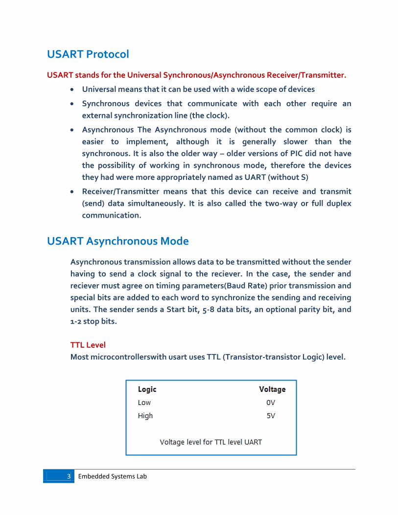
TTL Level
Most microcontrollerswith usart uses TTL (Transistor-transistor Logic) level.
4 Embedded Systems Lab
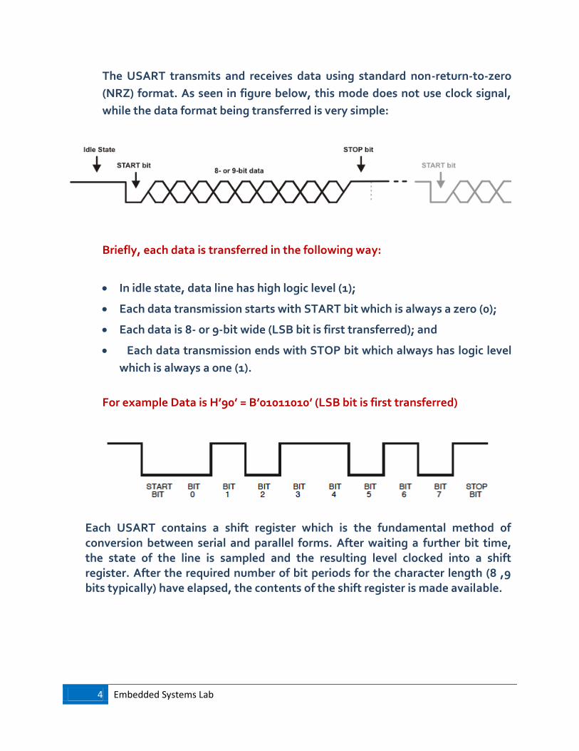
The USART transmits and receives data using standard non-return-to-zero
(NRZ) format. As seen in figure below, this mode does not use clock signal,
while the data format being transferred is very simple:
Briefly, each data is transferred in the following way:
In idle state, data line has high logic level (1);
Each data transmission starts with START bit which is always a zero (0);
Each data is 8- or 9-bit wide (LSB bit is first transferred); and
Each data transmission ends with STOP bit which always has logic level
which is always a one (1).
For example Data is H’90’ = B’01011010’ (LSB bit is first transferred)
Each USART contains a shift register which is the fundamental method of conversion between serial and parallel forms. After waiting a further bit time, the state of the line is sampled and the resulting level clocked into a shift register. After the required number of bit periods for the character length (8 ,9 bits typically) have elapsed, the contents of the shift register is made available.

5 Embedded Systems Lab
RS-232
The RS-232 standard defines the voltage levels that correspond to logical one and logical zero levels for the data transmission and the control signal lines. Valid signals are plus or minus 3 to 15 volts - the range near zero volts is not a valid RS-232 level.
Beside voltage level, RS-232 also has a few extra pins:

6 Embedded Systems Lab
RS-232 HW Connection
Concerning with voltage levels, all that is required (at the hardware) is an external level shifter to translate TTL signals from PIC to RS232 levels, and vice-versa. This can be achieved by using a MAX232 chip.

7 Embedded Systems Lab
USART Library Functions
Usart_Init Initializes hardware USART module with the desired baud rate.
Usart_Init(9600)
Usart_Data_Ready Function returns 1 if data is ready or 0 if there is no data. if Usart_Data_Ready () then ‘ or Usart_Data_Ready ()=1
‘read end if
Usart_Read Returns the received byte. If byte is not received, returns 0.
if Usart_Data_Ready () then portb = Usart_Read()
end if
Usart_Read_Text Reads characters received via USART until the delimiter sequence is detected (here:“ok”). The read sequence is stored in the parameter output (here:txt).
Usart_Read_Text(txt, “ok”) <<”hello ok”____txt:hello
Usart_Write Function transmits a byte (data) via USART.
Usart_Write(portb)
Usart_Write_Text Sends text (parameter uart_text) via USART. Text should be zero terminated.
Usart_Write_Text(“hello”)
If the device wants to load to USART: write (input is from his side)
If the device wants to load from USART: read (output is from his side)

8 Embedded Systems Lab
Serial communication from PIC to PC
Proteus
We will use virtual terminal (V.T.) for implementing PC
1. Write a basic program that sends a text from PIC to PC.
1. 2. Simulate the circuit using Proteus ISIS program.
Lab Work 1

9 Embedded Systems Lab
Double click << Change the baud rate to 9600
TX and RX are on pins C6 and C7, connect them to RX and TX of V.T.
<< MAX232 IC is already connected to the board >>
For all parts, Don’t forget to change the internal clock
frequency of the PIC to 8MHz
10 Embedded Systems Lab
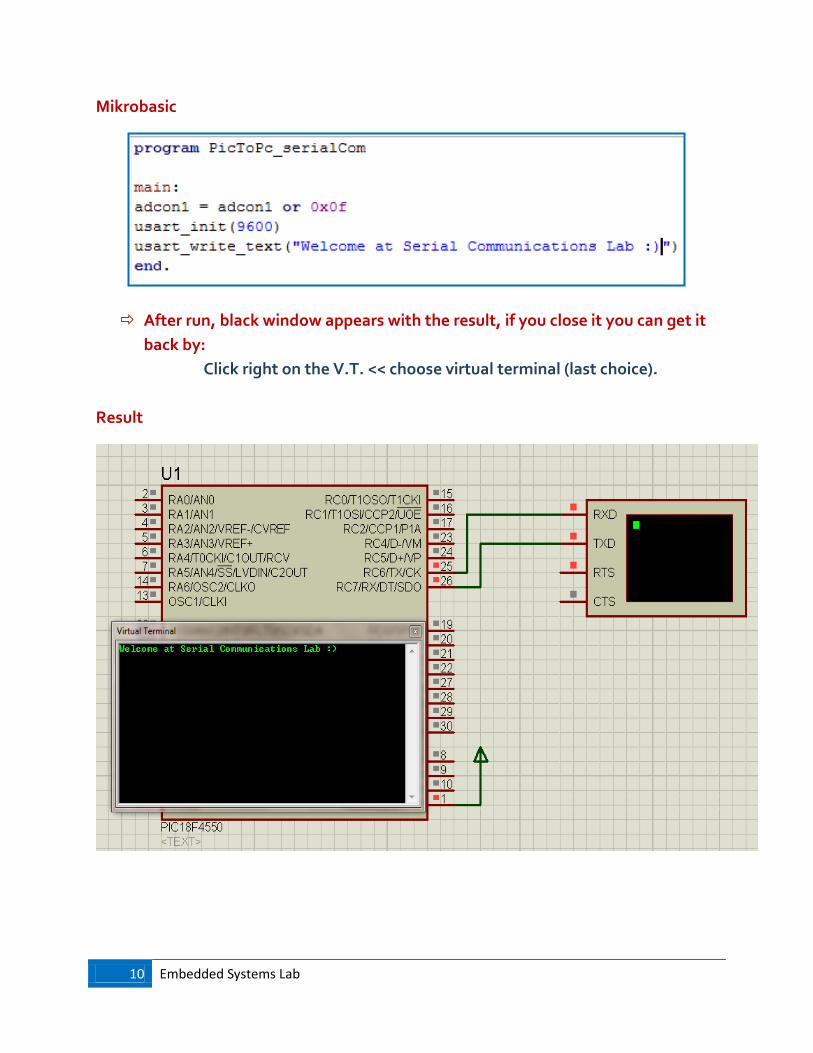
Mikrobasic
After run, black window appears with the result, if you close it you can get it
back by:
Click right on the V.T. << choose virtual terminal (last choice).
Result

11 Embedded Systems Lab
Serial communication from PC to PIC
Proteus
1. Write a basic program that sends a text from PC to PIC
and view on LCD.
2. Simulate the circuit using Proteus ISIS program.
Lab Work 2

12 Embedded Systems Lab
<< When you are typing the text, it will not appear onto the black window ..
continue your work, results will be appeared on LCD normally >>
Mikrobasic
Serial communication from PIC to PIC
1. Write a basic program that sends the state of switch from
master PIC to slave PIC (leds).
2. Simulate the circuit using Proteus ISIS program.
Lab Work 3
Every text must end with ‘$’ in
order to be read and shown on
LCD
(Choose any delimiter you want)
13 Embedded Systems Lab
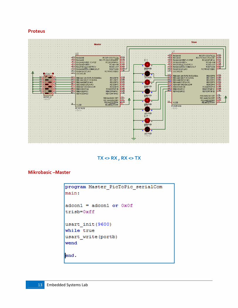
Proteus
TX <> RX , RX <> TX
Mikrobasic –Master
14 Embedded Systems Lab
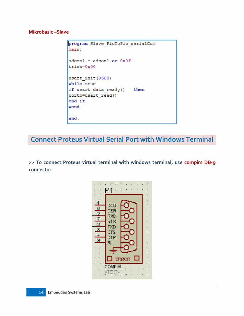
Mikrobasic –Slave
Connect Proteus Virtual Serial Port with Windows Terminal
>> To connect Proteus virtual terminal with windows terminal, use compim DB-9
connector.
15 Embedded Systems Lab
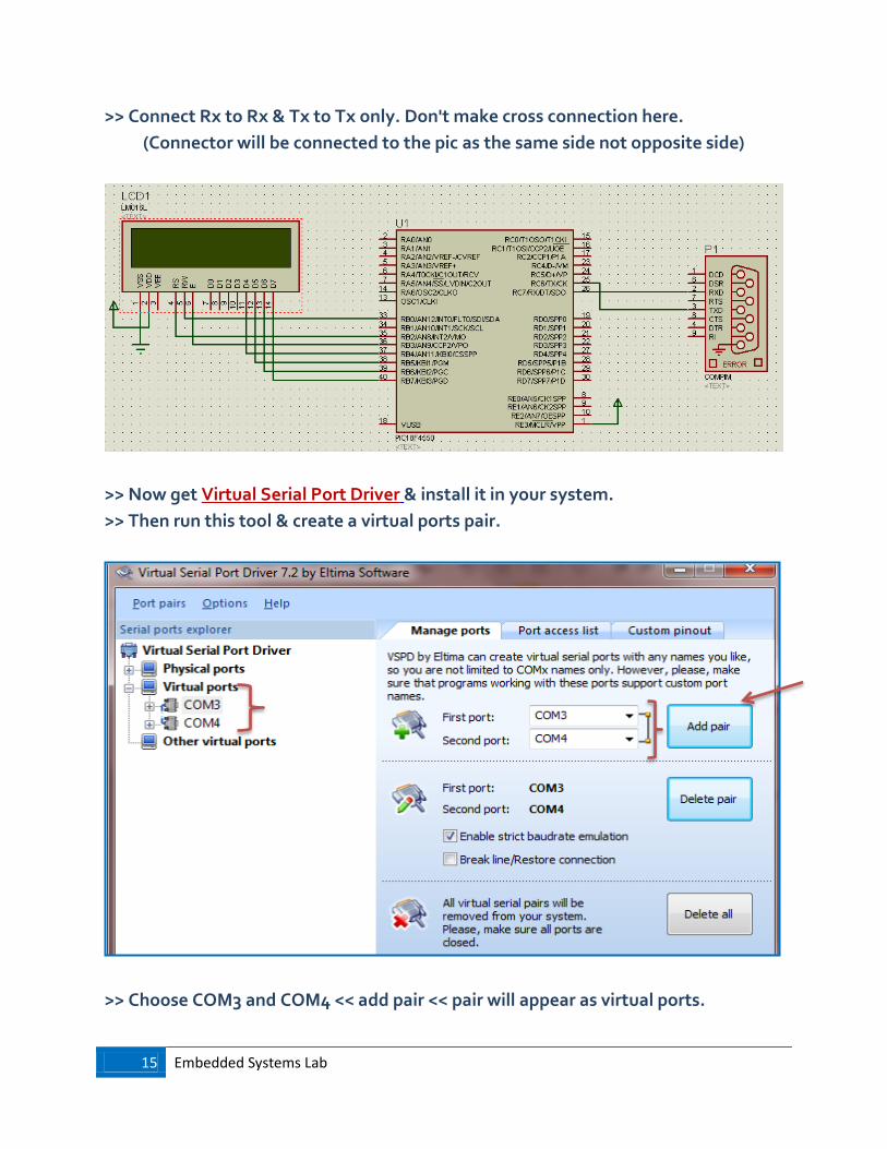
>> Connect Rx to Rx & Tx to Tx only. Don't make cross connection here.
(Connector will be connected to the pic as the same side not opposite side)
>> Now get Virtual Serial Port Driver & install it in your system.
>> Then run this tool & create a virtual ports pair.
>> Choose COM3 and COM4 << add pair << pair will appear as virtual ports.

16 Embedded Systems Lab
>> In order to be sure that you can work with these ports as a real prts on windows
chek this:
Computer << Click right <<properities << device manager: your ports are added!
>> Our work will depend on implementing the compim connecter (which is
connected to PIC) as a COM4 then send and receive data for a pic using it.
Double click << physical port: COM4, physical baud rate & virtual baud rate: 9600.

17 Embedded Systems Lab
Connection Establishment
In order to establish the communication, PC must have communication software
installed. One such communication terminal is part of MikroBasic IDE. It can be
accessed by clicking Tools > USART Terminal from the drop-down menu. Terminal
allows you to monitor transfer and to set all the necessary transfer settings. First of
all, we need to set the transfer rate to match the microcontroller's rate. Then, select
the appropriate communication port and finally press Connect button.

18 Embedded Systems Lab
COM3: USART Terminal Tool of Mikrobasic
COM4: COMPIM that connected to PIC at Proteus
<< Now your Proteus Tx, Rx & Terminal Tx Rx are cross connected >>
Mikrobasic
1. Write a basic program that sends the text from terminal
to the PIC side and view it on LCD.
2. Simulate the circuit using Proteus ISIS program.
Lab Work 4

19 Embedded Systems Lab
USART terminal
Proteus

20 Embedded Systems Lab
You can send text as typing by enabling this << text will appear on LCD as
soon as you type it.
1. Write a basic program that sends the text from the PIC
side to the terminal.
2. Simulate the circuit using Proteus ISIS program.
Lab Work 5

21 Embedded Systems Lab
Mikrobasic
Result (immediately after the Run)
22 Embedded Systems Lab
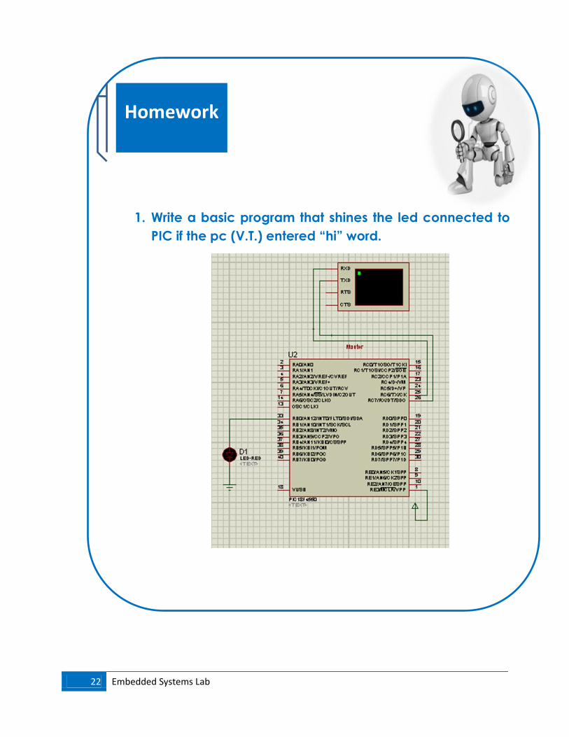
1. Write a basic program that shines the led connected to
PIC if the pc (V.T.) entered “hi” word.
Homework

23 Embedded Systems Lab
… Good Luck
… Good Luck …
2. Write a basic program that send the pressed number on
keypad to the terminal.
![AT11626: SAM D SERCOM USART Configurationww1.microchip.com/.../Atmel-42539-SAMD-SERCOM-USART-Configuration... · AT11626: SAM D SERCOM USART Configuration [APPLICATION NOTE] 3 Atmel-42539A-SAMD-SERCOM-USART-Configuration_ApplicationNote_AT11626_092015](https://img.pdfslide.net/doc/110x75/5e8569d49b115e518a2fc952/at11626-sam-d-sercom-usart-at11626-sam-d-sercom-usart-configuration-application.jpg)