Embed Size (px)
Citation preview
APS Common Alarm Indicator AS1200
APS systems AG Tel. +41 (0)62 389 88 88 Neumatt 4 Fax. +41 (0)62 389 88 80 CH- 4626 Niederbuchsiten www.aps-systems.ch e-mail: [email protected]
AS1200
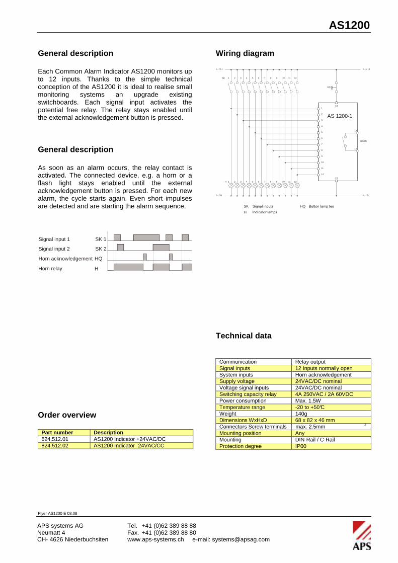
General description Each Common Alarm Indicator AS1200 monitors up to 12 inputs. Thanks to the simple technical conception of the AS1200 it is ideal to realise small monitoring systems an upgrade existing switchboards. Each signal input activates the potential free relay. The relay stays enabled until the external acknowledgement button is pressed.
General description As soon as an alarm occurs, the relay contact is activated. The connected device, e.g. a horn or a flash light stays enabled until the external acknowledgement button is pressed. For each new alarm, the cycle starts again. Even short impulses are detected and are starting the alarm sequence.
Order overview
Part number Description 824.512.01 AS1200 Indicator +24VAC/DC 824.512.02 AS1200 Indicator -24VAC/CC
Wiring diagram
Technical data
Communication Relay output Signal inputs 12 Inputs normally open System inputs Horn acknowledgement Supply voltage 24VAC/DC nominal Voltage signal inputs 24VAC/DC nominal Switching capacity relay 4A 250VAC / 2A 60VDC Power consumption Max. 1.5W Temperature range -20 to +50°C Weight 140g Dimensions WxHxD 68 x 82 x 46 mm Connectors Screw terminals max. 2.5mm 2 Mounting position Any Mounting DIN-Rail / C-Rail Protection degree IP00
Flyer AS1200 E 03.08
5 6 7 81 2 3 4
5 6 7 82 3 41H
9 10 11 12SK
9 10 11 12
1
2
3
4
5
6
7
8
9
10
11
12
L+ / L1
L- / N
L+ / L1
L+ / N
13
HQ
16
14
15
HORN
AS 1200-1
SK
H
Signal inputs HQ Button lamp tes
Signal input 1
Signal input 2
Horn acknowledgement
Horn relay
SK 1
SK 2
H
HQ
APS Common Alarm Indicator AS1210
APS systems AG Tel. +41 (0)62 389 88 88 Neumatt 4 Fax. +41 (0)62 389 88 80 CH- 4626 Niederbuchsiten www.aps-systems.ch e-mail: [email protected]
AS1210
General description
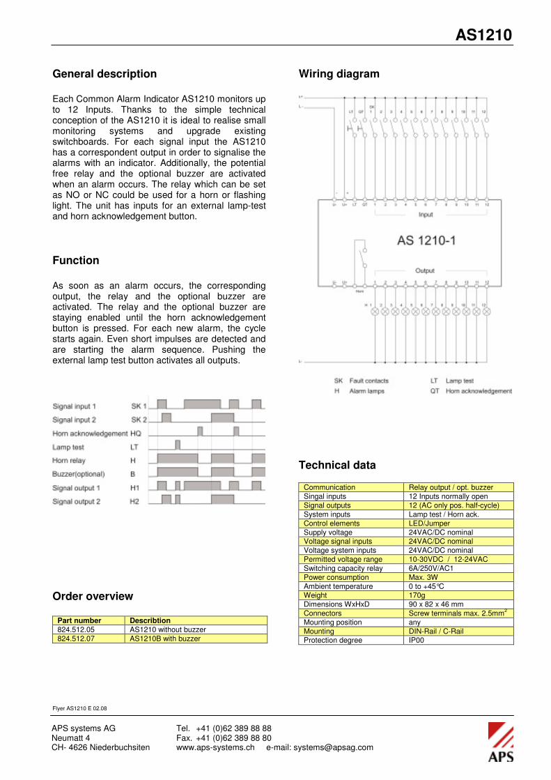
Each Common Alarm Indicator AS1210 monitors up to 12 Inputs. Thanks to the simple technical conception of the AS1210 it is ideal to realise small monitoring systems and upgrade existing switchboards. For each signal input the AS1210 has a correspondent output in order to signalise the alarms with an indicator. Additionally, the potential free relay and the optional buzzer are activated when an alarm occurs. The relay which can be set as NO or NC could be used for a horn or flashing light. The unit has inputs for an external lamp-test and horn acknowledgement button.
Function
As soon as an alarm occurs, the corresponding output, the relay and the optional buzzer are activated. The relay and the optional buzzer are staying enabled until the horn acknowledgement button is pressed. For each new alarm, the cycle starts again. Even short impulses are detected and are starting the alarm sequence. Pushing the external lamp test button activates all outputs.
Order overview
Part number Describtion
824.512.05 AS1210 without buzzer
824.512.07 AS1210B with buzzer
Wiring diagram
Technical data
Communication Relay output / opt. buzzer
Singal inputs 12 Inputs normally open
Signal outputs 12 (AC only pos. half-cycle)
System inputs Lamp test / Horn ack.
Control elements LED/Jumper
Supply voltage 24VAC/DC nominal Voltage signal inputs 24VAC/DC nominal
Voltage system inputs 24VAC/DC nominal
Permitted voltage range 10-30VDC / 12-24VAC
Switching capacity relay 6A/250V/AC1
Power consumption Max. 3W
Ambient temperature 0 to +45°C Weight 170g
Dimensions WxHxD 90 x 82 x 46 mm
Connectors Screw terminals max. 2.5mm2
Mounting position any
Mounting DIN-Rail / C-Rail Protection degree IP00
Flyer AS1210 E 02.08