Embed Size (px)
Citation preview

User’sManual
Yokogawa Electric Corporation
Model 810518802AQ2200-621/62210Gbit/s Optical Modulator
IM 810518802-01E1st Edition

IM810518802-01E i
Introduction Thank you for your purchasing of this AQ2200-621/622 10Gbit/s Optical Modulator. This user’s manual describes the functions, operating procedures, and handling precautions necessary to operate the AQ2200-621/622 in correct and safe manner. Before starting operation of this module, thoroughly read this manual to use the product properly. After reading this manual, always store it in a safe place where all concerned personnel can refer to it immediately. This manual is useful if the operator have forgotten proper operation steps during operation. In addition to this manual, two kinds of manuals shown below are provided for the AQ2200-621/622. Therefore, you need to read the following two manuals, as well as this user’s manual.
Manual Item Manual No. Description AQ2200-621/622 10Gbit/s Optical Modulator User’s Manual
IM810518802-01E This user’s manual. The manual describes all functions of the AQ2200-621/622 except for the communication functions, and proper operating procedures.
AQ2200-621/622 10Gbit/s Optical Modulator Remote Commands User’s Manual
IM810518802-17E This manual describes the communication functions (remote control functions) of the AQ2200-621/622.
Additionally, you must also read the manual for AQ2201/AQ2202 Frame Controller, a main unit, on which the AQ2200-621/622 is to be mounted. Furthermore, when performing the BER measurement of the 10Gbit/s-band optical interface by combining optional units, such as BERT module*1, light source module*2, and optical receiving module *3 of the AQ2200-series, thoroughly read relevant manuals.
*1: AQ2200-601 10Gbit/s BERT Module *2: AQ2200-111 DFB-LD Module *3: AQ2200-631 10Gbit/s Optical Receiver
Notes The contents of this manual are subject to change without prior notice as a result of continuing improvements to the instrument's performance and functions. The figures given in this manual may differ from the actual screen. Every effort has been made in the preparation of this manual to ensure the accuracy of its contents. However, should you have any questions or find any errors, please contact your nearest YOKOGAWA dealer. Copying or reproducing all or any part of the contents of this manual without the permission of Yokogawa Electric Corporation is strictly prohibited. This unit uses Montavista Linux.
Trademarks Montavista is a registered trademark or trademarks of Montavista Software, Inc. Linux is a registered trademark or trademarks of Linus Torvalds in the United States and/or other countries. Adobe, and Acrobat are trademarks of Adobe Systems Incorporated. In this manual, TM and ® marks are not indicated on the registered trademarks and/or trademarks of their respective companies. Other company and product names mentioned herein may be the trademarks of their respective owners.
Revisions 1st Edition: March 2005
1st Edition : March 2005 (YK) All Rights Reserved, Copyright © 2005 Yokogawa Electric Corporation

ii IM810518802-01E
Functions Described in This Manual and Version This manual is applicable to the version "01.00" of the AQ2200-621/622 10Gbit/s Optical Modulator (which is sometimes abbreviated as "EO" or "EO module") and the main unit version "04.00." or later of the AQ2201/AQ2202 Frame Controller, on which this module is to be mounted. The following Table shows the relationship among the main unit version, additional functions of this module, and applicable module. If your module does not have the latest version, you cannot use all functions described in this manual.
The version of the main unit can be checked through SOFT VERSION of the device information, which is displayed using the following operating procedures.
1. Press the [SYSTEM] key. → Move the cursor to "Information". 2. Press the <OK> function key or [ENTER] key.
For details about how to display the version of the main unit, see section 7.7, Displaying the device information, in the user’s manual for AQ2201/AQ2202 Frame Controller.
The version of this module can be checked through Rev info, which is displayed using the following operating procedures on the SUMMARY screen or BERT APPLICATION screen.
1. Press the <Information> function key. Check EO Firm of Rev info that appears after the above operation. For details about how to display the version of this module, see section 4.3-(7) or 5.6-(4), Displaying the version information, in this user's manual.
Versions of AQ2201/2202 Main Unit and AQ2200-621/622 EO Module Main Unit Version EO Version Suffix Code New Functions Reference Page/Section/Chapter 04.00 or later 01.00 Standard −

IM810518802-01E iii
Checking the Contents of the Package Unpack the box and check the contents before operating the instrument. If some of the contents are not correct or missing or if there is physical damage, contact the dealer from whom you purchased them.
AQ2200-621/622 EO Module Check that the model name and suffix code given on the name plate on the right side of the module unit match those on the order. When contacting the dealer from which you purchased the instrument, please give them the instrument number.
Right Side View <AQ2200-621 10Gbit/s Optical Modulator (1.55um)>
MODEL SUFFIX Specifications 810518802 AQ2200-621 10Gbit/s Optical Modulator configuration with
standard specifications (1.55um) X-cut/Z-cut -X
-Z Cutting direction of LN modulator: X-cut
Cutting direction of LN modulator: Z-cut Optical connector -S
-F SC connector
FC connector Options /P
/U PMF (FC/APC-SC/PC) for 1.5um
U-link coaxial cable <AQ2200-622 10Gbit/s Optical Modulator (1.31um)>
MODEL SUFFIX Specifications 810518804 AQ2200-622 10Gbit/s Optical Modulator configuration with
standard specifications (1.31um) X-cut/Z-cut -X
-Z Cutting direction of LN modulator: X-cut
Cutting direction of LN modulator: Z-cut Optical connector -S
-F SC connector
FC connector Options /P
/U PMF (FC/APC-SC/PC) for 1.3um
U-link coaxial cable
No. (Instrument Number) When contacting the dealer from which you purchased the instrument, please give them the instrument number.

Checking the Contents of the Package
iv IM810518802-01E
Standard Accessories The standard accessories below are supplied with the instrument. Check that all contents are present and that they are undamaged.
Name Q’ty Remarks Protective cap 2 This protective cap is already attached to the optical terminals. Terminator for circuit protection 1 This terminator is already attached to the electrical terminal. User’s Manual 1 This manual. User’s Manual for remote commands 1
Optional Accessories (Sold Separately) The optional accessories below are available for purchase separately. Check that all contents are present and that they are undamaged. For information and ordering, contact your nearest YOKOGAWA dealer.
Name Q’ty Remarks U-link coaxial cable 1 For connection with DATAOUT of BERT module PMF (FC/APC-SC/PC) for 1.5um 1 For AQ2200-621 (0.5m)
For connection with 1.55um-light source module PMF (FC/APC-SC/PC) for 1.3um 1 For AQ2200-622 (0.5m)
For connection with 1.31um-light source module
IM810518802-01E v
Safety Precautions This instrument is an IEC safety class I instrument (provided with terminal for protective earth grounding). The general safety precautions described herein must be observed during all phases of operation. If the instrument is used in a manner not specified in this manual, the protection provided by the instrument may be impaired. Yokogawa Electric Corporation assumes no liability for the customer's failure to comply with these requirements.
The Following Symbols Are Used on This Instrument. Warning: handle with care. Refer to the user’s manual or service manual. This symbol appears on dangerous locations on the instrument which require specialinstructions for proper handling or use. The same symbol appears in the corresponding place in the manual to identify those instructions.
Hazard, radiation of laser apparatus
Make sure to comply with the precautions below. Not complying might result in injury or death.
WARNING Power Supply Before connecting the power cord, ensure that the source voltage matches the rated supply voltage of the instrument and that it is within the maximum rated voltage of the provided power cord. Power Cord and Plug To prevent the possibility of electric shock or fire, be sure to use the power cord supplied by YOKOGAWA. The main power plug must be plugged into an outlet with a protective earth terminal. Do not invalidate this protection by using an extension cord without protective earth grounding. Protective Grounding Make sure to connect the protective earth to prevent electric shock before turning ON the power. The power cord that comes with the instrument is a three-pin type power cord. Connect the power cord to a properly grounded three-pin outlet. Necessity of Protective Grounding Never cut off the internal or external protective earth wire or disconnect the wiring of the protective earth terminal. Doing so poses a potential shock hazard. Defective Protective Grounding Do not operate the instrument if the protective earth or fuse might be defective. Make sure to check them before operation. Do Not Operate in an Explosive Atmosphere Do not operate the instrument in the presence of flammable liquids or vapors. Operation in such environments constitutes a safety hazard. Do Not Remove Covers The cover should be removed by YOKOGAWA’s qualified personnel only. Opening the cover is dangerous, because some areas inside the instrument have high voltages. External Connection Securely connect the protective grounding before connecting to the item under measurement or an external control unit. If you are going to touch the circuit, make sure to turn OFF the circuit and check that no voltage is present.

Safety Precautions
vi IM810518802-01E
In Using the Modules • Do not apply input voltage exceeding the maximum input voltage, withstand voltage, or
allowable surge voltage. • To prevent the possibility of electric shock, be sure to furnish protective earth grounding
of the main frame. • To prevent the possibility of electric shock, be sure to fasten the module screws.
Otherwise, the electrical protection function and the mechanical protection function will not be activated.
• Avoid continuous connection under an environment in which the allowable surge voltage or greater voltage may occur.
InGaAs The devices used in this product contains indium gallium arsenide (InGaAs). Particles and vapors of InGaAs are very dangerous. The product must therefore never be burnt, destroyed, cut, crushed or chemically disassembled. It must be separated from general industrial waste and household rubbish, and disposed of according to local regulations. Disposal of the Unit When disposing of this unit, do not attempt to throw it into the fire. Doing so may cause the unit to explode, resulting in fire, personal injury, or burn hazard. Laser Light Source The laser light source is not used in this module, but the invisibility laser light is output when connecting it with other laser light source modules that have been released as AQ2200 multi-application system. • Do not output the laser beam if the optical fiber is not connected to the optical output
connector. • Before disconnecting the optical fiber from the optical output connector, stop the optical
output completely. • Never look at the optical output connector or the top end of the optical fiber connected to
the optical output connector while the laser beam is being output. The invisible laser beam cannot be seen. However, if the laser beam enters your eye(s), this may cause eye injury and the eyesight to be ruined excessively. In detail, please refer to the manual for AQ2201/AQ2202 Frame Controller. It is described to the Chapter of "Safety Precautions; Cautions about Safe Operation of Laser Product".

IM810518802-01E vii
How To Use This Manual Structure of This Manual
This user's manual consists of the following sections:
Chapter Title Description 1 Functional Description
This Chapter describes the overview of this unit, part names and functions, measurement principle and function of this unit. This Chapter does not describe the operating procedures. However, when reading this Chapter before starting each operation, the contents of operation can be understood easily.
2 Before Starting Measurement This Chapter describes the unpacking and acceptance inspection, cautions on operation, how to mount or remove the module, and how to connect the cables.
3 Basic Operation This Chapter describes the panel part names, various screens, and their functions.
4 Operation on SUMMARY/DETAIL Screens This Chapter describes the display screen, setup screen, and operation examples on the SUMMARY and DETAIL screens.
5 BERT Application This Chapter describes the BERT application display screen, setup screen, parameter setting, and measuring procedures focusing on the EO/OE module.
6 Troubleshooting, Maintenance, and Inspection This Chapter describes probable causes and corrective actions if any trouble occurs, and the maintenance and inspection of this module.
7 Daily Maintenance This Chapter describes the daily maintenance of this module.
8 Specifications This Chapter describes the specifications of this module.
Appendix This Appendix describes the initial set values and outside views of this module.

How To Use This Manual
viii IM810518802-01E
Conventions Used in This Manual Used Characters In the operational description, keys are indicated as described below. • Hard key: [ ] • Parameter item: " " • Function key: < >
Symbols The following symbols are used in this manual.
Improper handling or use can lead to injury to the user or damage to the
instrument. This symbol appears on the instrument to indicate that the user must refer to the user's manual for special instructions. The same symbol appears in the corresponding place in the user's manual to identify those instructions. In the manual, the symbol is used in conjunction with the word "WARNING" or "CAUTION."
Calls attention to actions or conditions that could cause serious or fatal injury to the user, and precautions that can be taken to prevent such occurrences.
Calls attentions to actions or conditions that could cause light injury to the user or damage to the instrument or user’s data, and precautions that can be taken to prevent such occurrences.
Note Calls attention to information that is important for proper operation of the instrument.
Symbols Used for Descriptions of Operations The following symbols are used in Chapters 2 to 7 to distinguish certain features in descriptions.
Carry out steps in the order shown. The operating procedures are given
with the assumption that you are not familiar with the operation. Thus, it may not be necessary to carry out all the steps when changing settings.
Describes settings and restrictions relating to the operation. A detailed description of the function is not provided. For a detailed description of the function, refer to Chapter 1.
WARNING
CAUTION
Operating Procedures
Explanation

IM810518802-01E ix
Cautions on Handling of Optical Fiber and Optical Connector
Dust and Contamination Are Strictly Prohibited. The contamination of the optical connector may cause the performance to deteriorate. Always keep the optical connector clean. Additionally, when the optical fiber and optical connector are not used, attach the cap supplied with this module to the optical fiber and optical connector of this unit to prevent the dust from entering or the optical fiber and optical connector from being contaminated.
Cleaning the Optical Fiber Before using this module, clean the top end of the optical fiber plug using a wiping paper sheet with a small amount of absolute alcohol put or blow off dirt or dust with a spray for optical parts.
Cleaning the Optical Connector Turn OFF the power to this unit. Twist a wiping paper sheet thinly and put a small amount of absolute alcohol on it. With this wiping paper sheet, clean the inside of the optical connector or blow off dirt or dust with a spray for optical parts.
Handling the Optical Fiber The top end of the optical fiber is sensitive. If the optical fiber is made in contact with the screw when connecting it to the connector, its top end is damaged, causing the performance to deteriorate. Therefore, when connecting the optical fiber, always handle the top end of the optical fiber with great care. If the optical fiber is not used, attach the cap to the optical fiber to protect its top end.
Handling the Optical Connector Carefully connect the optical fiber to the optical connector so that the laser beam emitted from the optical connector does not enter your eye. If the optical connector is not used, attach the cover to the optical signal input/output terminals.
Always keep the optical fiber and optical connector clean.
Using the Optical Attenuator Check the absolute maximum light receiving level of the mating unit, to which this unit is connected. If the signal level exceeds this level, take appropriate protective measures, such as connection of the optical attenuator.
CAUTION

x IM810518802-01E
Contents Introduction..................................................................................................................i Functions Described in This Manual and Version ...................................................... ii Checking the Contents of the Package ..................................................................... iii Safety Precautions .....................................................................................................v How To Use This Manual.......................................................................................... vii Cautions on Handling of Optical Fiber and Optical Connector .................................. ix
Chapter 1 Functional Description 1.1 Overview....................................................................................................... 1-1 1.2 Part Names and Functions ........................................................................... 1-2 1.3 Block Diagram .............................................................................................. 1-4 1.4 Functional Description .................................................................................. 1-5
Chapter 2 Before Starting Measurement
2.1 Unpacking and Acceptance Inspection......................................................... 2-1 2.2 Handling Precautions.................................................................................... 2-2 2.3 Mounting the Module .................................................................................... 2-3 2.4 Removing the Module................................................................................... 2-4 2.5 Connecting the Cables ................................................................................. 2-5
Chapter 3 Basic Operation 3.1 Flow of Operation ......................................................................................... 3-1 3.2 Panel Part Names and Functions ................................................................. 3-2 3.3 Various Screens and Functions .................................................................... 3-3
Chapter 4 Operation on SUMMARY/DETAIL Screens 4.1 Display Screen.............................................................................................. 4-1 4.2 Setup Screen................................................................................................ 4-2 4.3 Starting the Operation................................................................................... 4-4
Chapter 5 BERT Application 5.1 BERT Application.......................................................................................... 5-1 5.2 Display Screen.............................................................................................. 5-2 5.3 Setup Items................................................................................................... 5-7 5.4 Starting Up the BERT Application ............................................................... 5-10 5.5 Setting the Parameters ............................................................................... 5-12 5.6 Making a Measurement .............................................................................. 5-20
Chapter 6 Troubleshooting, Maintenance, and Inspection 6.1 Check Items Before Calling for the Service Engineer................................... 6-1 6.2 Maintenance and Inspection......................................................................... 6-4
Chapter 7 Daily Maintenance 7.1 Cleaning the Main Unit and Module.............................................................. 7-1 7.2 Cleaning the Optical Interface ...................................................................... 7-2 8.1 Specifications................................................................................................ 7-1

Contents
IM810518802-01E xi
9App
11
22
33
44
55
66
77
88
Appendix Appendix 1 Initial Set Values................................................................... Appendix-1 Appendix 2 Outside View ........................................................................ Appendix-2

Chapter 1 Functional Description
IM810518802-01E 1-1
21
Functional Description
1.1 Overview This unit is a 10Gbit/s-band optical modulation module (optical modulator) to be mounted on the AQ2200-series Frame Controller.
Major Features This module is a compact optical modulation module *2 to be mounted on the AQ2200-series Frame Controller. Applicable coding is NRZ and mark ratio is 1/2. An extinction ratio adjustment function is provided. The extinction ratio can be changed variably by adjusting the gain of the internal LN driver. A cross point adjustment function is provided. The cross point of the output waveform of the internal LN driver can be changed variably. An Auto Bias Control (ABC) ON/OFF function is provided. When this function is turned ON, the DC drift of the LN modulator can be corrected automatically. On the contrary, when this function is set at OFF, the DC bias can be set manually. An ABC Bias Slope switch function is provided. The polarity at the DC bias point of the LN modulator can be switched. This optical modulation module can easily be made applicable to the BER measurement of the 10Gbit/s-band optical interface by combining it with the BERT module *3, light source module *4, and/or optical receiving module *5 of the AQ2200-series. By combining various modules of the AQ2200-series, a test system is constructed easily, in which the BERT is integrated with other applications.
*1: AQ2201 Frame Controller (3-slot type) AQ2202 Frame Controller (9-slot type) *2: AQ2200-621 10Gbit/s Optical Modulator (1550nm) AQ2200-622 10Gbit/s Optical Modulator (1310nm) *3: AQ2200-601 10Gbit/s BERT Module *4: AQ2200-111 DFB-LD Module *5: AQ2200-631 10Gbit/s Optical Receiver

1-2 IM810518802-01E
1.2 Part Names and Functions
Front Panel
No. Name Function [1] Lock button for removal Lock button for removal of the module. This lock button is used to mount or remove
this module on/from the frame controller. For details, see sections 2.3 and 2.4.
[2] Removal lever Lever for removal of the module. This removal lever is used to mount or remove this module on/from the frame controller. For details, see sections 2.3 and 2.4.
[3] DATA IN Data input terminal
Electric input, 1.2Vpp(Max) AC-coupling. Data input terminal. This terminal is connected to the DATA OUT (TO OPTICAL MODULATOR) terminal of the PPG of the BERT module with the U-link (optional) or coaxial cable. “500mVpp±100mVpp” is recommended for the input amplitude.
[4] LD IN LD input terminal
Optical input, 16dBm (Max). When using AQ2200-111 (with PMF option) for the light source, connect this terminal with the PANDA fiber (optional). When using other light source, adjust the Slow axis of the polarized wave to the connector key position. Additionally, to ensure the stable operation of the Auto Bias Control, it is recommended to input a CW light in a range of 9dBm to 13dBm.
[5] OPT OUT Optical output terminal
Optical output. The optical signal, the light intensity of which is modulated, is output.
Note When the performance stability of the extinction ratio is required, it is recommended
to use this module after it has been warmed up for about 100 min. after the power has been turned ON.
[1] Lock button for removal
[2] Removal lever
[3] DATA IN Data input terminal
[4] LD IN LD input terminal
[5] OPT OUT Optical output terminal
Front panel

1.2 Part Names and Functions
IM810518802-01E 1-3
21
Functional Description
Rear Panel
No. Name Function [1] Connector This connector is used to connect the frame controller. After checking that any
foreign matter is not sticking to the connector, mount the module on the frame controller.
[1] Connector
Rear panel

1-4 IM810518802-01E
1.3 Block Diagram Block Diagram
The following shows the block diagram of this module.
Description of Block Diagram This optical modulator uses Lithium Niobate (LN) (hereafter referred to as “LN modulator”). The data input to the DATA IN terminal is amplified by the Driver to supply it to the LN modulator. According to the above data, the intensity of the LD light, which is input from the LD INPUT terminal to the LN modulator, is modulated, and then it is output from the OPT OUT terminal. The control circuit controls the Driver Gain (Gain shown in the above Fig.) and Driver output cross point (Cross shown in the above Fig.). With this operation, the light waveform is controlled indirectly. The Auto Bias Control controls the feedback in order to automatically correct the DC drift of the LN modulator.
LN Modulator
DATA IN
LD IN PANDA
OPT OUT PANDA
Driver
Gain
Controlcircuit
Cross
DCBias
Auto-Bias Control
Data

IM810518802-01E 1-5
21
Functional Description
1.4 Functional Description (1) Driver Gain
The output amplitude setting of the internal LN driver output waveform and set value are displayed using the numeric values and graphs. As the output amplitude is changed, the extinction ratio can be changed. The setting range is 0 to 255. “0” shows the amplitude decrease (extinction ratio decrease) direction while “255” shows the amplitude increase (extinction ratio increase) direction.
* This shows a measurement example and does not guarantee the numeric values.
(2) Cross Point The cross point setting of the internal LN driver and set value are displayed using the numeric values and graphs. The cross point may depend on the ABC Slope. The setting range is –31 to 32.
* This shows a measurement example and does not guarantee the numeric values.
(3) ABC ON/OFF The ON/OFF setting of the auto bias control (ABC: Auto Bias Control) circuit can be made to automatically correct the DC drift of the LN modulator. When the ABC is set at ON, the ABC functions to automatically correct the DC drift of the LN modulator. When the ABC is set at OFF, the ABC does not function, allowing you to manually set the DC bias.
0 128 255 [digits]
Extinction ratio[dB] 14
2
-30 0 30 [digits]
Cross point[%] 70
30

1.4 Functional Description
1-6 IM810518802-01E
(4) ABC Slope Change-over When the ABC is set enabled, the polarity of the DC bias point of the LN modulator can be changed. It is possible to set whether the ABC is locked on the Positive (+) side or Negative (-) side.
Positive
Negative

Chapter 2 Before Starting Measurement
IM810518802-01E 2-1
2
Before Starting Measurement
2.1 Unpacking and Acceptance Inspection This unit has been mechanically and electrically inspected strictly to assure the proper operation before shipment from the factory. After this unit has been received, immediately unpack it to check for transportation damage.
Mechanical Inspection After unpacking this unit, check the appearance of this unit, switch operation, and connectors for transportation damage or functional fault. Additionally, make sure that all accessories are included while referring to the description stated in Chapter 8, Specifications.
To avoid serious electric shock trouble, do not carry out the functional test if transportation damage is found in the exterior (cover or panel).
Note It is recommended to carefully store inner corrugated boxes and cushion materials
except for consumable packaging materials, such as packaging paper sheets for reuse, such as re-transportation of the unit so that they are not damaged.
Functional Inspection When no fault is found in the mechanical operation, the functional test is actually carried out to check that the unit functions as specified and to inspect the performance.
If Any Damage or Fault Is Found: If any damage or trouble different from the specification is found in this unit during mechanical inspection or functional test after unpacking, immediately contact your local sales dealer, or YOKOGAWA’s sales department or sales branch office. The contact addresses of YOKOGAWA’s sales departments and sales branch offices are described at the back of this manual.
WARNING

2-2 IM810518802-01E
2.2 Handling Precautions Safety Precautions
The following describes the cautions about installation environment and handling. If you are using this instrument for the first time, make sure to thoroughly read the“Safety Precautions”given on page v to vi.
1. Do not apply any excessive impact to this unit. 2. Do not operate or store this unit in an environment beyond the specifications. 3. Do not place this unit close to an object that radiates the strong radio wave or magnetic
field. 4. Do not remove the cover of this unit. 5. Do not store or operate this unit in a place where the static electricity is produced. 6. Do not touch any metallic terminal of the connector of the module by hand.
Installation Environment Always operate this unit only in an indoor place. Do not operate this unit in a place where it is exposed to the outside atmosphere, flammable gas, or smoke.
This unit can be operated in the environmental range described below.
Temperature: 5 to 40°C Altitude: Up to 2000m Humidity: Relative humidity 20 to 80% Appropriate measures must be taken to avoid dew condensation caused by extreme temperature changes. Note When the performance stability of the extinction ratio is required, it is recommended
to use this module after it has been warmed up for about 100 min. after the power has been turned ON.
Ventilation requirements When installing this unit in a rack or cabinet, do not block any ventilation port in the rear or side panel of this unit. Additionally, mount this unit with sufficient ventilation kept so that the heat is not remained inside the rack or cabinet.
Do Not Install the Instrument in the Following Places. • In direct sunlight or near heat sources. • Where an excessive amount of soot, steam, dust, or corrosive gas is present. • Near strong magnetic field sources. • Near high voltage equipment or power lines. • Where the level of mechanical vibration is high. • In an unstable place.
CAUTION

IM810518802-01E 2-3
2
Before Starting Measurement
2.3 Mounting the Module 1. Pull up the lever with the button on the module panel kept pressed.
Note When mounting the module, always check the vertical orientation of the module.
2. Make the dent on the bottom of the module matched with the guide of a desired slot of the frame where the module is to be mounted, and then gradually insert the module.
3. When the module is inserted and it is in contact with the far side, gradually push the lever with strong
force until the button clicks.
Lever
Button
Button
Lever
Guide

2-4 IM810518802-01E
2.4 Removing the Module 1. Lightly push up the lever with the button kept pressed until the lever is unlocked. 2. Gradually pull up the lever until the module is projected approximately 1cm from the frame. 3. Gradually pull out the module from the slot of the frame.
Button
Lever
Lever

IM810518802-01E 2-5
2
Before Starting Measurement
2.5 Connecting the Cables (1) Optical IF Is Used.
The following shows the connections when the DUT has the optical interface and the BERT module (BERT)*1 is operated with it combined with the light source module (LS)*2, optical modulation module (EO)*3, and/or optical receiving module (OE)*4 of the AQ2200-series. *1: AQ2200-601 10Gbit/s BERT Module *2: AQ2200-111 DFB-LD Module *3: AQ2200-621 10Gbit/s Optical Modulator (1550nm) AQ2200-622 10Gbit/s Optical Modulator (1310nm) *4: AQ2200-631 10Gbit/s Optical Receiver Note To assure the performance, always use EO and OE optional units (sold
separately) for the optional U-link and PANDA fiber. To protect the DUT, insert the optical attenuator, when necessary.
OPT IN
DATA OUT
DATA IN1(CDR)
OPT OUT
OPT OUT OPTIN
DATA IN
DATA OUTTO OPTICAL MODULATOR
LD IN
DUT
OPT OUT
Optical fiberOptical fiber
PANDA fiber *
U-link (Coaxial)* OE BERT EO LS
U-link (Coaxial)*
Optical ATT

2.5 Connecting the Cables
2-6 IM810518802-01E
Connecting the Cables When connecting this unit to the DUT, other module, or measuring instrument with the connection cables, take appropriate measures to protect the unit from static electricity.
When connecting the cable or terminator to the connector of this unit, always ground it firmly or make the operator in contact with the metallic part of the main frame to prevent static electricity. If the static electricity is charged, this may cause the unit to malfunction.
Connector 1. If this unit is not used, attach the terminator to the coaxial connector and protective cap to
the optical connector. 2. Before connecting the cable to the connector, always turn OFF the outputs of the signal
generator and light source. 3. Tighten the coaxial connector with a torque wrench. The proper tightening torque is
0.9N-m. Excessive torque may cause the connector to break.
When connecting the U link cable or connection cable to the connector, make the connector of this unit matched with the connector type of the cable end and carry out the proper connection. If a connector other than that specified is connected, this may cause the connector to break.
CAUTION
CAUTION

Chapter 3 Basic Operation
IM810518802-01E 3-1
Basic Operation
3
3.1 Flow of Operation Flow of Operation
*: If you set PPG IF to Optic, no signal is output to the DATA OUT terminal nor the DATA OUT terminal.
Note Perform "Measurement conditions setup" and "Measurement" in the BERT
Application (Chapter 5 ).
Preparation
• Installation (→ Section 2.2, User's Manual for AQ2201/2202 Frame Controller) • Mounting the module (→ Section 2.3) • Connecting the power supply (→ User's Manual for AQ2201/2202 Frame Controller) • Connecting with the DUT (→ Section 2.5) • Connecting with a PC (→ User's Manual for AQ2201/2202 Frame Controller) • Turning ON the power switch (→ User's Manual for AQ2201/2202 Frame Controller)
Measurement Conditions Setup
• PPG IF conditions: Optic setting * (→ (2) in Section 5.5 of AQ2200-601 10Gbit/s BERT Module User's Manual [hereafter referred to as "10GBERT manual"])
• Measurement pattern and pattern length: PRBS/Prog, Length (→ (15) through (18) in Section 5.5 of 10GBERT manual)
• Error rate (→ (19) in Section 5.5 of 10GBERT manual) • Logic settings of PPG, ED, and EO (→ (4) in Section 5.5 of this manual, (20) in
Section 5.5 of 10GBERT manual) • DriverGain (→ (1) in Section 5.5) • CrossPoint (→ (2) in Section 5.5) • Auto Bias Control (→ (3) in Section 5.5) • Data threshold (→ (6) in Section 5.5) etc.
• Turning ON OFF the output (→ (3) in Section 5.6) • Starting the measurement (→ (1) in Section 5.6) • Adding the error (→ (2) in Section 5.6) • Stopping the measurement (→ (1) in Section 5.6) • Displaying the measurement result (→ Section 5.2)
Measurement
End For details, see the sections within parentheses.

3-2 IM810518802-01E
3.2 Panel Part Names and Functions (1) Display and Key Operation Console
[PRESET]: Returns the parameters of the module actually mounted on the frame to their default statuses. [SYSTEM]: Displays the SYSTEM SETUP screen. [DISP TOP]: Closes the PARAMETER CHANGE screen. *1 [FRAME]: When this key is pressed on the BERT APPLICATION screen, the tabs (pages) of the items to
be controlled are changed in the reverse direction. [APPLI]: Displays the APPLICATION SELECT screen. [HOLD]: When the module at the cursor position is the sensor, the updating of the measured data
display is stopped. *1 [CHAN]: When this button is pressed on the SUMMARY or DETAIL screen, the modules to be
controlled are changed in the slot No. order. When this button is pressed on the BERT APPLICATION screen, the tabs (pages) of the items to be controlled are changed in the normal direction.
[USER1]: A desired function can be assigned to this button. *1 [USER2]: A desired function can be assigned to this button. *1 [USER3]: A desired function can be assigned to this button. *1 [DETAIL]: Switches the display between the SUMMARY screen and DETAIL screen. [SHIFT]: Changes to the ten-key pad mode (numeric value direct input). *1: Not available when this module is installed.
Note For details, see the User’s Manual for AQ2201/AQ2202 Frame Controller.
DisplayShows the measured value, set value, and status.
Function keyKeys corresponding to the items shown on the right of the display. Function key is used to select or execute relevant item shown on the right of the display.
Cursor key[▲] and [▼] are used to change the module to be controlled, move the cursor, and change the numeric value. [◄] and [►] are used to change the numeric value input digit position and input a backspace or negative sign in the ten-key pad mode.
ENTER keyThis key is used to set the selected item and input value.
CANCEL keyThis key is used to cancel the operation.
POWER switchThis switch is used to turn ON or OFF the power.
Hard key 12 keys are arranged and they have the following functions.
ENTERCANCEL
AQ2201 FRAME CONTROLLER
POWER
OFF
ON
0
1 2 3
4 5 6
7 8 9
.
FRAME DETAIL CHAN
USER1
USER2
USER3
HOLD
SYSTEM
APPLI
PRESET SHIFT
DISPTOP
BS -

IM810518802-01E 3-3
Basic Operation
3
3.3 Various Screens and Functions (1) Display Screen
The display screen is mainly classified into five screens shown below. • INITIAL screen • SYSTEM screen • SUMMARY screen • DETAIL screen • APPLICATION screen
The following screen transition diagram shows the relationship among these screens.
Note For details about INITIAL screen and SYSTEM screen, see the User’s Manual for
AQ2201/AQ2202 Frame Controller.
See Chapter 5.
Power ON
INITIAL screen
SUMMARY screen SYSTEM screen
DETAIL screen APPLICATION screen
[SYSTEM]
[CLOSE]
[DETAIL]
[APPLI]
[APPLI]
[DETAIL] [SYSTEM]
[CLOSE]
*1 One or more module is inserted. *2 No module is inserted.
*1 *2
See Chapter 4.
See Chapter 4.
[SYSTEM]

3.3 Various Screens and Functions
3-4 IM810518802-01E
(2) SUMMARY Screen On the SUMMARY screen, the information on all mounted modules is displayed at once. You can display, check, and change the main parameters. The fields equivalent to the slots of the chassis are displayed. For details, see Chapter 4.
SUMMARY Screen of 9-Slot Type (AQ2202 FRAME CONTROLLER)
Note Contents common to SUMMARY screen, DETAIL screen, and APPLICATION screen.
Current module: Module with blue background This module allows changing of the parameters. The current modules are changed in the slot No. order with
the [CHAN] key or [ ] or [ ] key. Current parameter: Parameter with light blue background
This parameter can be changed. With the [ ] or [ ] key, the selection item of the current
parameter is changed.
Current module Module with blue background Current parameter Parameter with light blue background The slot not mounted is displayed as "NO MODULE".

3.3 Various Screens and Functions
IM810518802-01E 3-5
Basic Operation
3
(3) DETAIL Screen On the DETAIL screen, the detailed information on one module (current module) selected from those mounted is displayed. You can display, check, and change all parameters of the current module. For details, see Chapter 4.
(4) APPLICATION Screen The application is software that performs the control with one or multiple modules combined. Normally, use this BERT APPLICATION screen. For details, see Chapter 5.
Current module
Current parameter
Tab The tab of the slot that becomes the current module is displayed on the front (top).
Current parameter
Tab
Chapter 4 Operation on SUMMARY/DETAIL Screens
IM810518802-01E 4-1
24
Operation on SUMMARY/DETAIL Screens
4.1 Display Screen This section describes the display contents of the SUMMARY screen and DETAIL screen.
(1) SUMMARY Screen
(2) DETAIL Screen
9-slot Type Driver Gain
Shows the output amplitude setting of the internal LN driver. • Display range: 0 to 255
Cross Point Shows the cross point setting of the internal LN driver output waveform. • Display range: -31 to 32
Driver Gain Shows the output amplitude setting of the internal LN driver using the numeric value and graph. • Display range: 0 to 255
Cross Point Shows the cross point setting of the internal LN driver output waveform using the numeric value and graph. • Display range: -31 to 32
ABC Slope Shows the Slope setting status of the ABC. This item is displayed when the ABC is set at ON.
Auto Bias Ctrl Shows the ON/OFF status of the ABC.
LN Bias set Shows the DC bias voltage of the LN modulator. This item is displayed when the ABC is set at OFF.• Display range: -10.00 to 9.90V
Alarm The alarm status of the module is detected and it is shown. • TEMP
Shows the temperature alarm. Indication Description Red The temperature exceeds the upper limit of the
storage temperature. Since the component may be broken thermally in this status, the power supply from the frame to the module is automatically stopped. Immediately stop the operation and lower the ambient temperature.
Yellow The temperature exceeds the upper limit of the operating temperature. If the operation is continued, this may cause operation fault.
Green Correct status
• ABC Shows the status of the auto bias control (Auto Bias Control) circuit of the LN modulator.
Indication Status Green Correct Red Fault

4-2 IM810518802-01E
4.2 Setup Screen (1) Outline of DETAIL Screen
The items at the right end of the screen correspond to the function keys. Pressing a desired function key on the right of the items shown on the screen will change the item display or make the setting. Additionally, “More / ” is displayed on the bottom line of the function key display on this screen, showing that the function key display is shown on page of pages. When pressing the “More / ” function key, the screen is changed cyclically. The above Fig. shows an example of the function key when the screen is changed with the More key. The lower half portion of the screen shown in the Fig. above is the scroll display. This display can be scrolled with the [ ] or [ ] cursor key.
When pressing [Enter] with a function key pressed or an item cursor selected, the Setup popup screen will appear. Select an item with the [ ] or [ ] key and press the [ENTER] key or <OK> function key to set it. To set a numeric value, select a desired numeric value with the [ ] or [ ] key or input a numeric value directly with the ten-key pad. Normally, pressing the [SHIFT] key will enter the ten-key pad input status. However, when the popup screen is shown, you can input a numeric value with the ten-key pad even though the [SHIFT] key is pressed first. Additionally, to exit the popup screen without changing of settings, press the [CANCEL] key or <Cancel> function key.
Note In the optical modulator, the items you can set with the function keys are common to the
DETAIL screen and SUMMERY screen.
Operation of <More / >

4.2 Setup Screen
IM810518802-01E 4-3
24
Operation on SUMMARY/DETAIL Screens
(2) Screen Configuration Diagram
(3) Display and Setup Items Item Name Set Value Description Driver Gain 0 to 255
Step value: 1
The output amplitude setting of the internal LN driver output waveform and set value are displayed using the numeric values and graphs. As the output amplitude is changed, the extinction ratio can be changed. “0” shows the amplitude decrease (extinction ratio decrease) direction while “255” shows the amplitude increase (extinction ratio increase) direction.
Cross point -31 to 32 Step value:
1
The cross point setting of the internal LN driver and set value are displayed using the numeric values and graphs. The cross point may depend on the ABC Slope.
ABC Slope Positive / Negative The polarity of the DC bias point of the LN modulator is set and displayed when the Auto Bias Control (ABC) is made valid. Whether the ABC is locked on the Positive side or Negative side is set. • Positive: ABC is locked on the Positive side. • Negative: ABC is locked on the Negative side.
Auto Bias Ctrl [ABC Enable] *1
ON / OFF Whether or not the auto bias control (ABC: Auto Bias Control) circuit is operated to automatically correct the DC drift of the LN modulator is set. • ON: ABC is operated. • OFF: ABC is not operated.
LN Bias (Set) *2 -10.00 to 9.90[V] Step value:
0.01 [V]
The DC bias of the LN modulator is set manually. This item becomes valid only when the Auto Bias Ctrl is set at OFF. The setting change becomes invalid when the Auto Bias Ctrl is set at ON. When the setting of the Auto Bias Ctrl is changed from OFF to ON, the above set value will be lost (cleared).
*ABC Reset ⎯ The ABC alarm is reset. *Information ⎯ The type and version information of the optical modulator are displayed. *Preset ⎯ Each set value is returned to that set at shipment of the factory.
For details about factory default settings, see Appendix 1.
*: Operated only with function key. *1: Function key is shown in [ ]. *2: Function key is shown with the word(s) in ( ) omitted.
Screen name (Tab) Setup item Set value
Optical Modulator Driver Gain 0 to 255
Cross Point -31 to 32
ABC Slope Positive / Negative
Auto Bias Ctrl[ABC Enable] *1 ON / OFF
LN Bias (Set) *2 -10.00 to 9.90 [V]
*ABC Reset
*Information
*Preset
*: Operated only with function key.*1: Function key is shown in [ ].*2: Function key is shown with the word(s) in ( ) omitted.
4-4 IM810518802-01E
4.3 Starting the Operation (1) Setting the Gain of The Driver for the Optical Modulator
Operating Procedures
Explanation The output amplitude of the optical modulator driver is set and displayed.
DriverGain: 0 to 255 1 step
Note When changing the numeric value with the [ ] or [ ] key, the set value is set
accordingly. When “SHIFT” is displayed, the ten-key pad can be used. To use the ten-key
pad if “SHIFT” is not displayed, press the [SHIFT] key. If a value beyond the setting range of the specification is input with the ten-key
pad, and then the <OK> or [ENTER] key is pressed, a value most close to that within the setting range of the specification is then set.
To exit the popup screen without changing of settings, press the [CANCEL] key or <Cancel>.
(2) Change the numeric value with the ten-key pad or the [ ] or [ ] key.
(1) Press <Driver gain> or move the cursor to “Driver gain”, and then press the [ENTER] key.
(3) Press the <OK> or [ENTER] key.
Popup Screen
1. Press the [DETAIL] key to display the DETAIL screen or SUMMARY screen.
(Figs. used in the descriptions show the DETAIL screen.)
2. With the [CHAN] key, select Optical Modulator for the current module.
3. Press <Driver gain>, or move the cursor to “Driver gain” with the [ ] or [ ] key, and then press the [ENTER] key.
4. The Driver gain set popup screen will appear. Change the numeric value with the ten-key
pad or the [ ] or [ ] key, and then press the <OK> or [ENTER] key.
5. The Driver gain set popup screen will disappear and the set value is then set and displayed.
4.3 Starting the Operation
IM810518802-01E 4-5
24
Operation on SUMMARY/DETAIL Screens
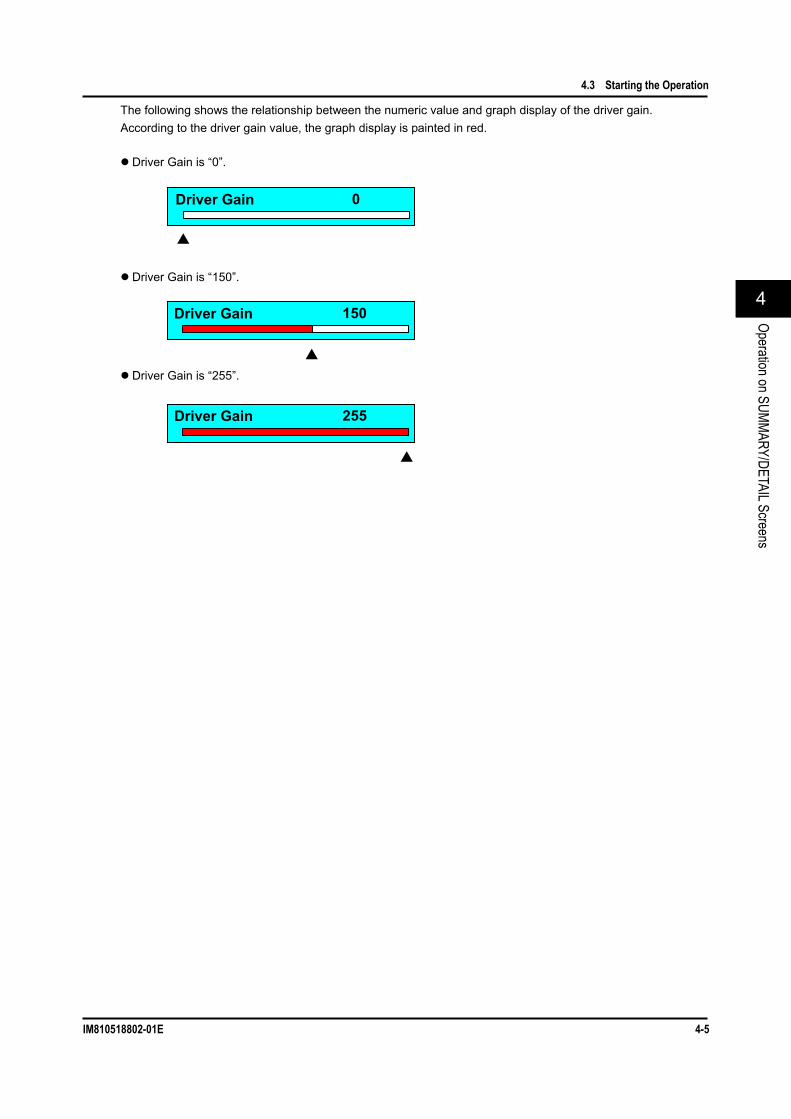
The following shows the relationship between the numeric value and graph display of the driver gain. According to the driver gain value, the graph display is painted in red.
Driver Gain is “0”.
Driver Gain is “150”.
Driver Gain is “255”.
255 Driver Gain
0 Driver Gain
Driver Gain 150

4.3 Starting the Operation
4-6 IM810518802-01E
(2) Setting the Cross Point of the Driver for the Optical Modulator
Operating Procedures
Explanation The cross point of the optical modulator driver is set and displayed.
Cross Point: -31 to 32 1 step
Note When changing the numeric value with the [ ] or [ ] key, the set value is set
accordingly. When “SHIFT” is displayed, the ten-key pad can be used. To use the ten-key
pad if “SHIFT” is not displayed, press the [SHIFT] key. If a value beyond the setting range of the specification is input with the ten-key
pad, and then the <OK> or [ENTER] key is pressed, a value most close to that within the setting range of the specification is then set.
To exit the popup screen without changing of settings, press the [CANCEL] key or <Cancel>.
(2) Change the numeric value with the ten-key pad or the [ ] or [ ] key.
(1) Press <Cross Point>, or move the cursor to "Cross Point", and then press the [ENTER] key.
(3) Press the <OK> or [ENTER] key.
Popup Screen
1. Press the [DETAIL] key to display the DETAIL screen or SUMMARY screen.
(Figs. used in the descriptions show the DETAIL screen.)
2. With the [CHAN] key, select Optical Modulator for the current module.
3. Press <Cross Point>, or move the cursor to "Cross Point" with the [ ] or [ ] key, and then press the [ENTER] key.
4. The Cross Point popup screen will appear. Change the numeric value with the ten-key
pad or the [ ] or [ ] key, and then press the <OK> or [ENTER] key.
5. The Cross Point popup screen will disappear and the set value is then set and displayed.

4.3 Starting the Operation
IM810518802-01E 4-7
24
Operation on SUMMARY/DETAIL Screens
The following shows the relationship between the numeric value and graph display of the cross point. According to the cross point value, the display position of the bar is changed.
Cross Point is “-31”.
Cross Point is “0”.
Cross Point is “32”.
32 Cross Point
Cross Point 0
-31 Cross Point

4.3 Starting the Operation
4-8 IM810518802-01E
(3) Selecting the ABC Slope
Operating Procedures
Explanation The ABC slope status of the optical modulator is set and displayed.
ABC Slope • Positive: ABC is locked on the Positive side. • Negative: ABC is locked on the Negative side.
Note This item becomes valid when "ON" is selected for the Auto Bias Ctrl.
When the Auto Bias Ctrl is set to OFF, this item is dimmed (shown in gray) and it cannot be selected.
To exit the popup screen without changing of settings, press the [CANCEL] key or <Cancel>.
Popup Screen
(2) Select Positive or Negative with the [ ] or [ ] key.
(1) Press <ABC Slope>, or move the cursor to "ABC Slope", and then press the [ENTER] key.
(3) Press the <OK> or [ENTER] key.
1. Press the [DETAIL] key to display the DETAIL screen or SUMMARY screen.
(Figs. used in the descriptions show the DETAIL screen.)
2. With the [CHAN] key, select Optical Modulator for the current module.
3. Press <ABC Slope>, or move the cursor to "ABC Slope" with the [ ] or [ ] key, and then press the [ENTER] key.
4. The ABC Slope popup screen will appear. With the [ ] or [ ] key, move the cursor to
either Positive or Negative, and press the <OK> or [ENTER] key.
5. The ABC Slope popup screen will disappear and the selected item is then set and displayed.

4.3 Starting the Operation
IM810518802-01E 4-9
24
Operation on SUMMARY/DETAIL Screens
(4) Resetting the ABC Alarm
Operating Procedures
Explanation The ABC Alarm is kept in red if the ABC alarm is detected even only once after the ABC Reset has been executed.
Note The ABC Reset (ABC reset) can be operated only with the function key.
To exit the popup screen without use of ABC Reset, press the [CANCEL] key or <Cancel>.
Popup Screen
(2) Press the <OK> or [ENTER] key.
(1) Press <ABC Reset>.
1. Press the [DETAIL] key to display the DETAIL screen or SUMMARY screen.
(Figs. used in the descriptions show the DETAIL screen.)
2. With the [CHAN] key, select Optical Modulator for the current module.
3. Press <ABC Reset>. 4. The ABC Reset popup screen will appear. To reset the ABC, press the <OK> or
[ENTER] key. 5. The ABC Reset popup screen will disappear
and the ABC is then reset.

4.3 Starting the Operation
4-10 IM810518802-01E
(5) Making the ABC Enabled
Operating Procedures
Explanation Whether or not the auto bias control (ABC) of the optical modulator is used is set and displayed.
Auto Bias Ctrl • ON: ABC is used (enabled). • OFF: ABC is not used (disabled).
Note When the Auto Bias Ctrl is set at OFF, the manual bias setup (LN Bias Set)
becomes valid. To exit the popup screen without changing of settings, press the [CANCEL] key or
<Cancel>.
Popup Screen
(2) Select ON or OFF with the [ ] or [ ] key.
(3) Press the <OK> or [ENTER] key.
(1) Press <ABC Enable>, or move the cursor to "Auto Bias Ctrl", and then press the [ENTER] key.
1. Press the [DETAIL] key to display the DETAIL screen or SUMMARY screen.
(Figs. used in the descriptions show the DETAIL screen.)
2. With the [CHAN] key, select Optical Modulator for the current module.
3. Press <ABC Enable>, or move the cursor to "Auto Bias Ctrl" with the [ ] or [ ] key, and then press the [ENTER] key.
4. The Auto Bias Ctrl popup screen will appear. With the [ ] or [ ] key, move the cursor to
either ON or OFF, and press the <OK> or [ENTER] key.
5. The Auto Bias Ctrl popup screen will disappear and the selected value is then set and displayed.

4.3 Starting the Operation
IM810518802-01E 4-11
24
Operation on SUMMARY/DETAIL Screens
(6) Setting the Bias Manually
Operating Procedures
Explanation The DC bias voltage of the optical modulator is manually set and displayed.
LN Bias Set: -10.00 to 9.90 [V] 0.01 [V] step
Note This item becomes valid when "OFF" is selected for the Auto Bias Ctrl.
When the Auto Bias Ctrl is set to ON, this item is dimmed (shown in gray) and it cannot be selected.
When the Auto Bias Ctrl is changed from OFF to ON, the values, which have been set when the Auto Bias Ctrl has been set at OFF, will be lost (cleared).
When changing the numeric value with the [ ] or [ ] key, the set value is set accordingly.
When “SHIFT” is displayed, the ten-key pad can be used. To use the ten-key pad if “SHIFT” is not displayed, press the [SHIFT] key.
If a value beyond the setting range of the specification is input with the ten-key pad, and then the <OK> or [ENTER] key is pressed, a value most close to that within the setting range of the specification is then set.
To exit the popup screen without changing of settings, press the [CANCEL] key or <Cancel>.
(2) Change the numeric value with the ten-key pad or the [ ] or [ ] key.
(3) Press the <OK> or [ENTER] key.
(1) Press <LN Bias>, or move the cursor to "LN Bias Set", and then press the [ENTER] key.
Popup Screen
1. Press the [DETAIL] key to display the DETAIL screen or SUMMARY screen.
(Figs. used in the descriptions show the DETAIL screen.)
2. With the [CHAN] key, select Optical Modulator for the current module.
3. Press <LN Bias>, or move the cursor to "LN Bias Set", and then press the [ENTER] key.
4. The LN Bias Set popup screen will appear. Change the numeric value with the ten-key
pad or the [ ] or [ ] key, and then press the <OK> or [ENTER] key.
5. The LN Bias Set popup screen will disappear and the set value is then set and displayed.

4.3 Starting the Operation
4-12 IM810518802-01E
(7) Displaying the Version
Operating Procedures
Explanation Note The Information (version display) can be operated only with the function key.
Popup Screen
(1) Press <Information>.
(2) Press the [ENTER] key.
1. Press the [DETAIL] key to display the DETAIL screen or SUMMARY screen.
(Figs. used in the descriptions show the DETAIL screen.)
2. With the [CHAN] key, select Optical Modulator for the current module.
3. Press <Information>. 4. The Information popup screen will appear. 5. Press the [ENTER] key, and the Information
popup screen will disappear.

4.3 Starting the Operation
IM810518802-01E 4-13
24
Operation on SUMMARY/DETAIL Screens
(8) Returning to the Factory Default Settings
Operating Procedures
Explanation Note The Preset (factory default setting) can be operated only with the function key.
For details about factory default setting (initial setting) values, see Appendix 1. To exit the popup screen without changing of settings, press the [CANCEL] key or
<Cancel>.
Popup Screen
(1) Press <Preset>.
(2) Press the <OK> or [ENTER] key.
1. Press the [DETAIL] key to display the DETAIL screen or SUMMARY screen.
(Figs. used in the descriptions show the DETAIL screen.)
2. With the [CHAN] key, select Optical Modulator for the current module.
3. Press <Preset>. 4. The Preset popup screen will appear. Press the <OK> or [ENTER] key. 5. The Preset popup screen will disappear, and
then the Optical Modulator is returned to its factory default settings.

Chapter 5 BERT Application
IM810518802-01E 5-1
55
BERT Application
5.1 BERT Application BERT Application
When operating the BERT module and BERT related module, it is convenient if you use this BERT application function. When operating the BERT application, the BER measurement can be performed while operating the related modules. For example, when monitoring the BER measurement results while adjusting the send/receive settings including the optical interface, it is convenient if you use this function.
The parameter items set in Chapter 4 are succeeded to the parameter items of the BERT APPLICATION. Additionally, the parameter items set in the BERT APPLICATION are also succeeded to the parameter items stated in Chapter 4.

5-2 IM810518802-01E
5.2 Display Screen (1) Description of Screen
The BERT APPLICATION screen consists of items shown below.
Measurement status display: Shows the operation status, progress status, elapsed time, and measurement result of the BER measurement module.
-1 Progress bar/Elapsed time display: Progress bar: Shows the progress status of the BER measurement using the
progress bar. When “Measure mode” is set at “Single", the progress bar shows the processed portion in green and unprocessed portion in white according to the progress status. As the status is progressed, the bar is painted from the left to the right. When “Measure mode” is set at "Manual", the bar is always shown in green regardless of the elapsed time.
Elapsed time display: Shows the elapsed time. [dd]:[hh]:[mm]:[ss], Max: 10 days = 10:00:00:00
• When “Measure mode” is set at "Single":
• When “Measure mode” is set at "Manual":
Measurement status display
-1 Progress bar/Elapsed time display
Tab
Setup item display (Page)
Function key
Status indication LED
-3 Operation status display
-2 Logging display -4 Measurement
result display
BERT APPLICATION Screen (PPG page)
Processed portion (Green)
Unprocessed portion (White)
Elapsed time
The progress bar shows the progress status of the BER measurement when compared to the measurement time set in the Measure day/Measure time. The processed portion is shown in green while the unprocessed portion is shown in white.
Elapsed time
The bar is always shown in green regardless of the elapsed time.
The progress bar is always shown in green regardless of the progress status of the BER measurement.

5.2 Display Screen
IM810518802-01E 5-3
55
BERT Application
-2 Logging display: Shows the execution status of the logging process using the indicator. Item Description Log Shows the execution status of the logging process.
“Green”: The logging process is running. * “Gray”: The logging process is stopped.
*: The BER measurement is being executed with “Logging” set at ON on the UTL page.
-3 Operation status display: Shows the operation status of the BER measurement module using the indicators.
Item Description System clock err Shows the system clock status.
“Green”: Correct status “Red”: Faulty status
In the faulty status, the following may be the cause according to the Clock Mode you have selected.
Internal: The built-in SG is faulty. REF Clk: The input reference clock is faulty. EXT Clk: The input external 10G-clock is faulty.
Err on Shows the error add ON/OFF status of the PPG. “Green”: Error add ON status “Gray”: Error add OFF status
This indication is interlocked with the Error add LED in the function key. Output Shows the output signal ON/OFF status of the PPG.
“Green”: Output signal ON status “Gray”: Output signal OFF status
This indication is interlocked with the Signal output LED in the function key. CDR ulk Shows the operation status of the CDR function of the ED (regeneration of the clock
synchronized with the input data signal). “Green”: Clock regeneration succeeded status “Gray”: Clock regeneration failed status
Sync-los Shows the synchronization status of the ED. “Red”: Sync loss status “Off”: Synchronization established status
Bit-err Shows the bit error detection status of the ED. “Red”: Bit error detection status “Off”: Correct status
OPT Los *1 Shows the Los (Loss of signal) detection status of the OE. “Red”: OPT Los status “Off”: Correct status
*1: Displayed only when EO/OE is mounted.

5.2 Display Screen
5-4 IM810518802-01E
-4 Measurement result display: Shows the BER measurement results using the status and numeric value. On the measurement result display, the item to be displayed can be changed during measurement. Up to two desired items can be selected from Syn-Loss, Error Count, Error Rate, TX Bitrate, RX Bitrate, and Received opt pwr *1. For details about operating procedures, see section 5.5 (1).
Item Description Syn-los Shows the synchronization status of the ED using the indicators and sync loss time [unit: us].
• Synchronization status indicator display “Green”: Synchronization has been established between measurement start and current
operation. “Yellow”: Synchronization was not established in the past, but it is established currently. “Red” Sync loss status
• Sync loss time Display range: 0 to 999999999 [us] and
1.000000E+09 to 8.640000E+11 [us] Err-cnt Shows the coding error status of the receive data of the ED using the indicators, and also
shows the number of coding errors (number of bit errors) [unit: bit]. • Coding error status indicator display
“Green”: No error has occurred between measurement start and current operation. “Yellow”: Error occurred in the past, but no error occurs currently. “Red”: Error status
• Number of coding errors Display range: 0 to 999999999 [bit] and
1.000000E+09 to 9.780480E+15 [bit] Err-rate Shows the coding error rate (error rate) of the receive data of the ED using the numeric value.
• Coding error rate Display range: 0.000000E-10 (to E-16) *4 (error free) to 1.022444E-16 (error occurs.) to 1.000000E-00 (all are errors.)
TX bitrate *2 *3 Shows the send bitrate of the PPG using the numeric value. • Send bitrate
Display range: 9.950000 to 11.320000 [Gbit/s] PPG clk Shows the status of the clock to be input to the PPG using the indicators.
• PPG clock indicator display “Green”: Correct status “Red”: Error status
RX bitrate *2 *3 Shows the receive bitrate of the ED using the numeric value. • Receive bitrate
Display range: 9.950000 to 11.320000 [Gbit/s] ED clk Shows the receive clock status of the ED using the indicators.
• Indicator display of receive clock of ED “Green”: Correct status “Red”: Error status
Received opt power *1 *2
Shows the average optical input power to be input to the receiver using the numeric value (simple power monitor). • Average optical input power
Display range: -19.0dBm to +3.0dBm Beyond display range: <-19dBm >+3dBm
*1: Displayed only when OE is mounted. *2: TX bitrate / RX bitrate / Received opt power. The measurement results are not displayed,
but the current status is monitored and displayed. *3: Since the internal SG is not synchronized with the measurement clock, a slight frequency
error to the set value may occur. *4: The exponential may vary depending on the period of measurement. However, the
resulting value is identical.

5.2 Display Screen
IM810518802-01E 5-5
55
BERT Application
Tab: Shows the screen name (= page) of the currently displayed setup item display. Press the [FRAME] key or [CHAN] key, or move the cursor to a tab or press the [ ] or [ ] key to change the page.
Setup item display (page): Shows the setup item related to the tab position. When the cursor is located on the setup item, press the [ENTER] key. You can change the set value. For details about each screen name of the BERT application, see (2). For details about screen configuration diagram, and display and setup items, see section 5.3. For details about operating procedures, see section 5.5.
Function key: When pressing a key on the right of the LCD on the front panel of the frame controller, you can start operation corresponding to the screen display.
Item Description Start mes Starts the measurement.
The measurement status is shown using the LED. (See also Start mes.) Stop mes Stops the measurement. Error add Turns ON or OFF the error add.
The error add status is shown using the LED. (See also Error add.) Signal output Turns ON or OFF the data output and clock output of the PPG. The output status is shown
using the LED. (See also Signal output.) Information Shows the firmware version.
Status indication LED: Shows the status of relevant function key process. When this process is running, the LED is shown in green.
Item Name Color Description Start mes Green Shows the measurement status using the LED.
Lit (Green): Measurement is in progress. Off (Gray): Measurement is stopped.
Error add Green Shows the error add status using the LED. Lit (Green): Error add is activated. Off (Gray): Error add is not activated (normal status).
Signal output Green Shows the output status of the data/clock of the PPG using the LED. Lit (Green): Data/Clock is being output. Off (Gray): Data/Clock output is stopped.
[CHAN] key or [ ] key
[FRAME] key or [ ] key
The page is changed in the normal direction.
The page is changed in the invert direction.
5.2 Display Screen
5-6 IM810518802-01E
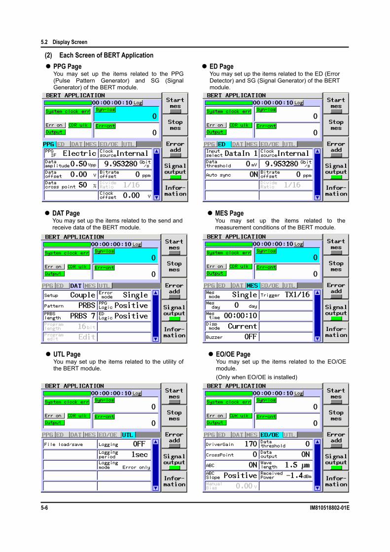
(2) Each Screen of BERT Application 4
PPG Page You may set up the items related to the PPG (Pulse Pattern Generator) and SG (Signal Generator) of the BERT module.
ED Page You may set up the items related to the ED (Error Detector) and SG (Signal Generator) of the BERT module.
DAT Page You may set up the items related to the send and receive data of the BERT module.
MES Page You may set up the items related to the measurement conditions of the BERT module.
UTL Page You may set up the items related to the utility of the BERT module.
EO/OE Page You may set up the items related to the EO/OE module. (Only when EO/OE is installed)

IM810518802-01E 5-7
55
BERT Application
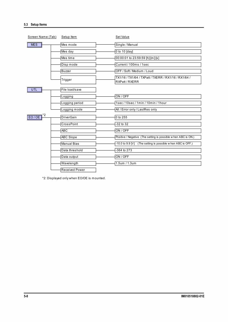
5.3 Setup Items (1) Screen Configuration Diagram
Screen Nam e (Tab) Setup Item Set Value
PPG PPG IF Electric / Optic
Data am plitude 0.50 to 2.00 [Vpp]
Data offset -2.00 to 3.00 [V]
Data cross point 30 to 70 [%]
Clock source Internal / REF Clk / Ext Clock
Bitrate 9.95 to 11.32 [Gbit/s ]
Bitrate Offset -100 to 100 [ppm ]
Divide ratio 1/16 / 1/64
Clock offset -2.00 to 3.00 [V]
ED Input select Data In1 / Data In2
Data threshold-350 to 350 [m V] when Input select is Data In 1(CDR).-300 to 300 [m V] when Input select is Data In 2(Norm al).
Auto sync ON / OFF
Clock source Internal / REF Clk / Ext Clock
Bitrate 9.95 to 11.32 [Gbit/s ]
Bitrate Offset -100 to 100 [ppm ]
Divide ratio 1/16 / 1/64
DAT Setup PPG / ED / Couple
Pattern PRBS / Prog256 / {Prog64M} *1
PRBS lengthPRBS7 / PRBS9 / PRBS10 / PRBS11 / PRBS15 / PRBS23 /PRBS31
Program length 16 to 256 [bit] / {256 to 67,108,864 [bit]}*1
Program edit 00 to FF in hexadecim al notation, 0/1 in binary notation.
Error m odeSingle / 1.0E-3 / 1.0E-4 / 1.0E-5 / 1.0E-6 / 1.0E-7 / 1.0E-8 /1.0E-9 / 1.0E-10 / 1.0E-11 / 1.0E-12
PPG Logic Pos itive / Negative
ED Logic Pos itive / Negative
*1: Item s in { } are valid only when optional function is selected.
5.3 Setup Items
5-8 IM810518802-01E
Screen Nam e (Tab) Setup Item Set Value
MES Mes m ode Single / Manual
Mes day 0 to 10 [day]
Mes tim e 00:00:01 to 23:59:59 [h]:[m ]:[s ]
Disp m ode Current / 100m s / 1sec
Buzzer OFF / Soft / Medium / Loud
TriggerTX1/16 / TX1/64 / TXPatt / TXERR / RX1/16 / RX1/64 /RXPatt / RXERR
UTL File load/save
Logging ON / OFF
Logging period 1sec / 10sec / 1m in / 10m in / 1hour
Logging m ode All / Error only / Las tRes only
EO / OE DriverGain 0 to 255
CrossPoint -32 to 32
ABC ON / OFF
ABC Slope Positive / Negative (The setting is possible w hen ABC is ON.)
Manual Bias -10.0 to 9.9 [V] (The setting is possible w hen ABC is OFF.)
Data threshold -364 to 273
Data output ON / OFF
Wavelength 1.5um / 1.3um
Received Power
*2: Displayed only when EO/OE is m ounted.
*2

5.3 Setup Items
IM810518802-01E 5-9
55
BERT Application
(2) Display and Setup Items Display and Setup Items of EO/OE Page
Item Name Setting Range Description DriverGain 0 to 255
Step value: 1 The output amplitude of the optical modulator driver is set and displayed.
Cross point -31 to 32 Step value:
1
The cross point of the optical modulator driver is set and displayed.
ABC ON / OFF Whether or not the auto bias control (ABC) of the optical modulator is used is set and displayed. • ON: ABC is used. • OFF: ABC is not used.
ABC Slope Positive / Negative
The ABC slope status of the optical modulator is set and displayed. This item can be set when the ABC is set at ON. • Positive: ABC is locked on the Positive side. • Negative: ABC is locked on the Negative side.
Manual Bias -10.0 to 9.9 [V] Step value: 0.01 [V]
The DC Bias voltage of the optical modulator is set and displayed. This item can be set when the ABC is set at OFF.
Data threshold -364 to 273 Step value: 1
The data threshold value of the optical receiver is set and displayed.
Data output ON / OFF The data output of the optical receiver is turned ON or OFF. • ON: Output is turned ON. • OFF: Output is turned OFF (GND-level).
Wavelength 1.5um / 1.3um
The wavelength band of the receiving light is set and displayed. •1.5um: When the wavelength of the receiving light is 1.5um-band •1.3um: When the wavelength of the receiving light is 1.3um-band
Received Power ⎯ The average light receiving power of the optical receiver is shown.
* For details about setup and display items of other pages, see the User's Manual for AQ2200-601 10Gbit/s BERT Module.

5-10 IM810518802-01E
5.4 Starting Up the BERT Application Operating Procedures
Note The left portion of the module you have selected becomes the concave indication while that of
unselected module becomes the convex indication. The BERT module is always selected and you cannot make it unselected (inactive). You cannot select the light source module. To do so, you must make the settings on the SUMMARY
screen/DETAIL screen.
(2) Press the <OK> or [ENTER] key.
(1) With the [ ] or [ ] key, move the cursor to "BERT".
APPLICATION SELECT Screen
(4) Press <Select>.
(3) With the [ ] or [ ] key, move the cursor to "desired module you want to use".
(5) Press <Start>.
MODULE SELECT Screen
Popup Screen
1. When pressing the [APPLI] key on the front panel of the frame controller, the APPLICATION SELECT screen will appear.
2. With the [ ] or [ ] key, move the cursor so that "BERT" becomes the current parameter, and press the <OK> or [ENTER] key. The MODULE SELECT screen will appear.
Note Pressing <Back> will return to the
APPLICATION SELECT screen.
3. In the BERT application, move the cursor with the [ ] or [ ] key so that "desired module you want to use" becomes the current parameter, and press <Select>.
4. If there are multiple modules you want to select, repeat step 3.
5. When pressing <Start>, the popup message, “"Caution" Start Application OK?”, will appear.
Note To close the screen, press the <Close> or
[CANCEL] key.

5.4 Starting Up the BERT Application
IM810518802-01E 5-11
55
BERT Application
Note Precautions for staring/stopping the BERT application
(1) If you start or stop the BERT application during a measuring operation, the measuring operation will be cancelled.
(2) When staring the BERT application, the previous values are kept retained and used as the preset values. However, Error add and OUTPUT become OFF.
BERT APPLICATION Screen (PPG Page)
Popup Screen
(6) Press <OK>.
From MODULE SELECT Screen
Note To close the screen, press the <Close> or
[CANCEL] key.
6. If no problems are found, press <OK>. The popup message, "Now Setting", will appear and the BERT application is started up.

5-12 IM810518802-01E
5.5 Setting the Parameters (1) Setting the Gain of the Driver for the Optical Modulator (DriverGain)
Operating Procedures
Explanation The output amplitude of the optical modulator driver is set and displayed.
DriverGain: 0 to 255 1 step
Note When changing the set value with the [ ] or [ ] key, it is set accordingly.
When "SHIFT" is displayed, the ten-key pad can be used. To use the ten-key pad if "SHIFT" is not displayed, press the [SHIFT] key.
If a value out of the setting range of the specification is input with the ten-key pad, and then the <OK> or [ENTER] key is pressed, a value most close to that within the setting range of the specification is then set.
For the function, see section 1.4.
Popup Screen
(1) Move the cursor to "DriverGain" and press the [ENTER] key.
(2) With the ten-key pad or the [ ] or [ ] key, change the numeric value.
(3) Press the <OK> or [ENTER] key.
1. With the [CHAN] or [FRAME] key, select EO/OE for the current module.
2. With the [ ], [ ], [ ], or [ ] key, move the cursor so that "DriverGain" becomes the current parameter and press the [ENTER] key.
3. The DriverGain popup screen will appear. With the ten-key pad or the [ ] or [ ] key,
change the numeric value and press the <OK> or [ENTER] key.
4. The DriverGain popup screen will disappear and the set value is then set and displayed.

5.5 Setting the Parameters
IM810518802-01E 5-13
55
BERT Application
(2) Setting the Cross Point of the Driver for the Optical Modulator (CrossPoint)
Operating Procedures
Explanation The cross point of the optical modulator driver is set and displayed.
CrossPoint: -31 to 32 1 step
Note When changing the set value with the [ ] or [ ] key, it is set accordingly.
When "SHIFT" is displayed, the ten-key pad can be used. To use the ten-key pad if "SHIFT" is not displayed, press the [SHIFT] key.
If a value out of the setting range of the specification is input with the ten-key pad, and then the <OK> or [ENTER] key is pressed, a value most close to that within the setting range of the specification is then set.
For the function, see section 1.4.
Popup Screen
(1) Move the cursor to "CrossPoint" and press the [ENTER] key.
(2) With the ten-key pad or the [ ] or [ ] key, change the numeric value.
(3) Press the <OK> or [ENTER] key.
1. With the [CHAN] or [FRAME] key, select EO/OE for the current module.
2. With the [ ], [ ], [ ], or [ ] key, move the cursor so that "CrossPoint" becomes the current parameter and press the [ENTER] key.
3. The CrossPoint popup screen will appear. With the ten-key pad or the [ ] or [ ] key,
change the numeric value and press the <OK> or [ENTER] key.
4. The CrossPoint popup screen will disappear and the set value is then set and displayed.
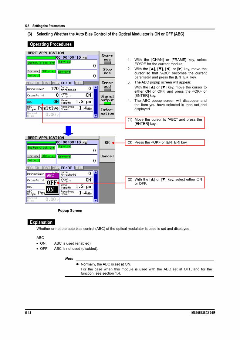
5.5 Setting the Parameters
5-14 IM810518802-01E
(3) Selecting Whether the Auto Bias Control of the Optical Modulator Is ON or OFF (ABC)
Operating Procedures
Explanation Whether or not the auto bias control (ABC) of the optical modulator is used is set and displayed.
ABC • ON: ABC is used (enabled). • OFF: ABC is not used (disabled).
Note Normally, the ABC is set at ON.
For the case when this module is used with the ABC set at OFF, and for the function, see section 1.4.
Popup Screen
(1) Move the cursor to "ABC" and press the [ENTER] key.
(2) With the [ ] or [ ] key, select either ON or OFF.
(3) Press the <OK> or [ENTER] key.
1. With the [CHAN] or [FRAME] key, select EO/OE for the current module.
2. With the [ ], [ ], [ ], or [ ] key, move the cursor so that "ABC" becomes the current parameter and press the [ENTER] key.
3. The ABC popup screen will appear. With the [ ] or [ ] key, move the cursor to
either ON or OFF, and press the <OK> or [ENTER] key.
4. The ABC popup screen will disappear and the item you have selected is then set and displayed.

5.5 Setting the Parameters
IM810518802-01E 5-15
55
BERT Application
(4) Selecting the ABC Slope of the Optical Modulator (ABC Slope)
Operating Procedures
Explanation The ABC slope status of the optical modulator is set and displayed.
ABC Slope • Positive: ABC is locked on the Positive side. • Negative: ABC is locked on the Negative side.
Note This item becomes valid when “ON” is selected for the ABC.
When the ABC is set to OFF, this item is dimmed (shown in gray) and it cannot be selected.
For the function, see section 1.4.
Popup Screen
(1) Move the cursor to "ABC Slope" and press the [ENTER] key.
(2) With the [ ] or [ ] key, select either Positive or Negative.
(3) Press the <OK> or [ENTER] key.
1. With the [CHAN] or [FRAME] key, select EO/OE for the current module.
2. With the [ ], [ ], [ ], or [ ] key, move the cursor so that "ABC Slope" becomes the current parameter and press the [ENTER] key.
3. The ABC Slope popup screen will appear. With the [ ] or [ ] key, move the cursor to
either Positive or Negative, and press the <OK> or [ENTER] key.
4. The ABC Slope popup screen will disappear and the item you have selected is then set and displayed.

5.5 Setting the Parameters
5-16 IM810518802-01E
(5) Setting the DC Bias of the Optical Modulator Manually (Manual Bias)
Operating Procedures
Explanation The DC bias voltage of the optical modulator is manually set and displayed.
Manual Bias: -10.0 to 9.9 [V] 0.01 [V] step
Note This item becomes valid when “OFF” is selected for the ABC. When the ABC is set
to “ON”, this item is dimmed (shown in gray) and it cannot be selected. When changing the set value with the [ ] or [ ] key, it is set accordingly. When "SHIFT" is displayed, the ten-key pad can be used.
To use the ten-key pad if "SHIFT" is not displayed, press the [SHIFT] key. If a value out of the setting range of the specification is input with the ten-key pad,
and then the <OK> or [ENTER] key is pressed, a value most close to that within the setting range of the specification is then set.
For the function, see section 1.4.
Popup Screen
(1) Move the cursor to "Manual Bias" and press the [ENTER] key.
(2) With the ten-key pad or the [ ] or [ ] key, change the numeric value.
(3) Press the <OK> or [ENTER] key.
1. With the [CHAN] or [FRAME] key, select EO/OE for the current module.
2. With the [ ], [ ], [ ], or [ ] key, move the cursor so that "Manual Bias" becomes the current parameter and press the [ENTER] key.
3. The LN Bias Set popup screen will appear. With the ten-key pad or the [ ] or [ ] key,
change the numeric value and press the <OK> or [ENTER] key.
4. The LN Bias Set popup screen will disappear and the set value is then set and displayed.

5.5 Setting the Parameters
IM810518802-01E 5-17
55
BERT Application
(6) Setting the Data Threshold Value of the Optical Receiver (Data Threshold)
Operating Procedures
Explanation The data threshold value of the optical receiver is set and displayed.
Data threshold: -364 to 273 1 step
Note When changing the set value with the [ ] or [ ] key, it is set accordingly.
When "SHIFT" is displayed, the ten-key pad can be used. To use the ten-key pad if "SHIFT" is not displayed, press the [SHIFT] key.
If a value out of the setting range of the specification is input with the ten-key pad, and then the <OK> or [ENTER] key is pressed, a value most close to that within the setting range of the specification is then set.
For details of the function, see the User's Manual for AQ2200-631 10Gbit/s Optical Receiver.
Popup Screen
(1) Move the cursor to "Data threshold" and press the [ENTER] key.
(2) With the ten-key pad or the [ ] or [ ] key, change the numeric value.
(3) Press the <OK> or [ENTER] key.
1. With the [CHAN] or [FRAME] key, select EO/OE for the current module.
2. With the [ ], [ ], [ ], or [ ] key, move the cursor so that "Data threshold" becomes the current parameter and press the [ENTER] key.
3. The Data threshold popup screen will appear.
With the ten-key pad or the [ ] or [ ] key, change the numeric value and press the <OK> or [ENTER] key.
4. The Data threshold popup screen will disappear and the set value is then set and displayed.

5.5 Setting the Parameters
5-18 IM810518802-01E
(7) Turning ON Or OFF the Data Output of the Optical Receiver (Data Output)
Operating Procedures
Explanation Whether the data output of the optical receiver is turned ON or OFF is set and displayed.
Data output • ON: Data is being output. • OFF: Data output is stopped (GND level).
Note For details of the function, see the User's Manual for AQ2200-631 10Gbit/s Optical
Receiver.
Popup Screen
(1) Move the cursor to "Data output" and press the [ENTER] key.
(2) With the [ ] or [ ] key, select either ON or OFF.
(3) Press the <OK> or [ENTER] key.
1. With the [CHAN] or [FRAME] key, select EO/OE for the current module.
2. With the [ ], [ ], [ ], or [ ] key, move the cursor so that "Data output" becomes the current parameter and press the [ENTER] key.
3. The Data output popup screen will appear. With the [ ] or [ ] key, move the cursor to
either ON or OFF, and press the <OK> or [ENTER] key.
4. The Data output popup screen will disappear and the item you have selected is then set and displayed.
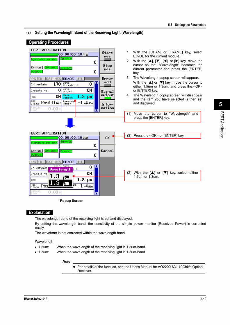
5.5 Setting the Parameters
IM810518802-01E 5-19
55
BERT Application
(8) Setting the Wavelength Band of the Receiving Light (Wavelength)
Operating Procedures
Explanation The wavelength band of the receiving light is set and displayed. By setting the wavelength band, the sensitivity of the simple power monitor (Received Power) is corrected easily. The waveform is not corrected within the wavelength band.
Wavelength • 1.5um: When the wavelength of the receiving light is 1.5um-band • 1.3um: When the wavelength of the receiving light is 1.3um-band
Note For details of the function, see the User's Manual for AQ2200-631 10Gbit/s Optical
Receiver.
Popup Screen
(1) Move the cursor to "Wavelength" and press the [ENTER] key.
(2) With the [ ] or [ ] key, select either 1.5um or 1.3um.
(3) Press the <OK> or [ENTER] key.
1. With the [CHAN] or [FRAME] key, select EO/OE for the current module.
2. With the [ ], [ ], [ ], or [ ] key, move the cursor so that "Wavelength" becomes the current parameter and press the [ENTER] key.
3. The Wavelength popup screen will appear. With the [ ] or [ ] key, move the cursor to
either 1.5um or 1.3um, and press the <OK> or [ENTER] key.
4. The Wavelength popup screen will disappear and the item you have selected is then set and displayed.

5-20 IM810518802-01E
5.6 Making a Measurement (1) Starting Or Stopping the BER Measurement
Operating Procedures
Explanation LED indication in <Start mes>
Indication Status Lit (indicated in green) Measurement is in progress. Off (indicated in gray) Measurement is stopped.
Note Before executing the BER measurement (Start mes is turned ON), set the Signal
output to ON (indicated in green). If you attempt to start the BER measurement with the Signal output set at OFF (indicated in gray), the ED enters the sync loss status and the measurement cannot be started.
If you press <Startmes> during the BER measurement, the BER measurement will restart.
If any of the following ED setting items is changed or reset during a BER measurement, the BER measurement will restart: Mes mode, Mes day, Mes time, Pattern, PRBS length, Program length, Program edit.
(1) Press <Start mes>. The LED in <Start mes> is lit during
measurement.
(2) Press <Stop mes>. The LED in <Start mes> is off during
stopping of the measurement.
Starting the Measurement 1. On the BERT APPLICATION screen, press
<Start mes> to start the BER measurement. The LED in <Start mes> is lit (indicated in
green) during measurement.
Stopping the Measurement 2. When pressing <Stop mes> during BER
measurement, the BER measurement is stopped.
The LED in <Start mes> is off (indicated in gray) during stopping of the measurement.

5.6 Making a Measurement
IM810518802-01E 5-21
55
BERT Application
(2) Adding the Error Or Stopping the Error Add
Operating Procedures
Explanation LED indication in <Error add>
Indication Status Lit (indicated in green) Error add is performed. Off (indicated in gray) Error add is stopped.
When the set update duration elapses while the time display has been set in the Disp mode, the counter (Syn-los/Err-cnt/Err-rate) of the measurement result display is cleared.
(1) Press <Error add>. The LED in <Error add> is lit during
execution of the error add.
(2) Press <Error add>. The LED in <Error add> is off during
stopping of the error add.
Indicated in red. Current error detection status
Shows the number of bit errors detected in the ED.
Indicated in yellow. The error occurred in the past, but the error does not occur currently.
Shows the number of bit errors detected in the ED.
Adding the Error1. On the BERT APPLICATION screen, press
<Error add> to add an error to the output data from the PPG. The LED in <Error add> is lit (indicated in green) during execution of the error add.
Stopping the Error Add 2. When pressing <Error add> during execution
of the error add, the error add to the output data of the PPG is stopped. The LED in <Error add> is off (indicated in gray) during stopping of the error add.
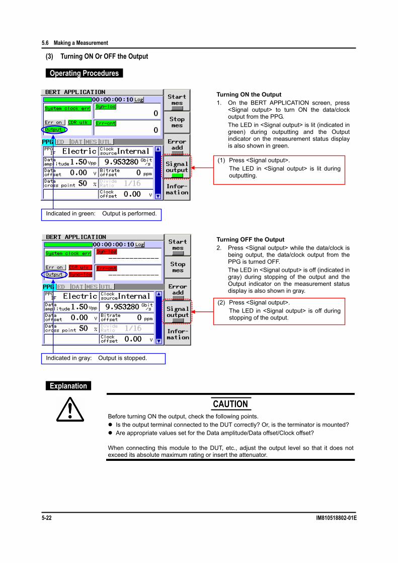
5.6 Making a Measurement
5-22 IM810518802-01E
(3) Turning ON Or OFF the Output
Operating Procedures
Explanation
Before turning ON the output, check the following points.
Is the output terminal connected to the DUT correctly? Or, is the terminator is mounted? Are appropriate values set for the Data amplitude/Data offset/Clock offset?
When connecting this module to the DUT, etc., adjust the output level so that it does not exceed its absolute maximum rating or insert the attenuator.
(1) Press <Signal output>. The LED in <Signal output> is lit during
outputting.
(2) Press <Signal output>. The LED in <Signal output> is off during
stopping of the output.
Indicated in green: Output is performed.
Indicated in gray: Output is stopped.
Turning OFF the Output 2. Press <Signal output> while the data/clock is
being output, the data/clock output from the PPG is turned OFF.
The LED in <Signal output> is off (indicated in gray) during stopping of the output and the Output indicator on the measurement status display is also shown in gray.
Turning ON the Output 1. On the BERT APPLICATION screen, press
<Signal output> to turn ON the data/clock output from the PPG.
The LED in <Signal output> is lit (indicated in green) during outputting and the Output indicator on the measurement status display is also shown in green.
CAUTION

5.6 Making a Measurement
IM810518802-01E 5-23
55
BERT Application
LED/Output indicator in <Signal output>
Indication Status Green Output is performed (ON status). Gray Output is stopped (OFF status).
Note The Signal output can also be turned ON or OFF with the OUTPUT ON/OFF
switch on the panel of the BERT module. This setting is interlocked with the operation.
To use the PPG output, turn ON the Signal output (indicated in green). If you attempt to start the BER measurement with the Signal output set at OFF
(indicated in gray), the sync loss occurs and the measurement cannot be started.

5.6 Making a Measurement
5-24 IM810518802-01E
(4) Displaying the Version Information
Operating Procedures
Explanation Contents of Rev info
The version of the selected module is displayed.
Popup Screen
(1) Press <Information>.
(2) Press the <Information>, [ENTER], or [CANCEL] key.
Displaying the Version Information 1. On the BERT APPLICATION screen, press
<Information>. The Rev Info popup screen will appear, showing the version information on each of the selected module.
Clearing the Version Display 2. When pressing <Information> or the [ENTER]
key or [CANCEL] key while the Rev Info popup screen is being displayed, the Rev info popup screen will disappear and the screen is then returned to the previous screen.

Chapter 6 Troubleshooting, Maintenance, and Inspection
IM810518802-01E 6-1
Troubleshooting, Maintenance, and Inspection
86
6.1 Check Items Before Calling for the Service Engineer
Troubleshooting If your system does not function correctly, check the following items before calling for the service engineer.
Trouble Probable Cause Corrective Action Related Section The power cable or connector is not connected firmly.
Check the connections of the power cable and connector. If any cable or connector is loose, connect it firmly.
The power is not turned ON.
The fuse is blown out. Check the fuse of the frame controller. If the fuse is blown out, replace it.
Common items
The operation panel cannot be operated.
The unit is put in the remote mode.
When <LOCAL> is indicated on the function key, this shows that the unit is in the remote mode, such as GP-IB. To operate the operation panel, cancel the remote mode from the remote controller or press <LOCAL> to put the unit in the local mode.
User's Manual for AQ2201 / 2202
The cable is not connected firmly.
Check the cable connection. If any cable is loose, connect it firmly.
The Interface setting of the PPG is not set at "Electric".
Check the IF setting of the PPG. If the IF setting is set at "Optic", change the setting to "Electric".
The input port setting is incorrect.
Check the input port settings (DATAIN1, DATAIN2) of the ED and actual connections. If the settings are different from the actual connections, make the settings matched with the connections.
Section 5.5 of BERT manual (hereafter, called BERT)
The PPG output is not ON. Check the Signal output. If the Signal output is OFF, change the output to ON.
Section 5.6 (3)
The setting of the PPG is not matched with that of the ED. (Setting: Pattern, PRBS length, Program length, Logic, etc.)
Check the DAT setting of the PPG and ED. If the setting of the PPG is different from that of the ED, make these settings matched with each other.
The amplitude of the data is small.
Check the value of the Data amplitude. If the amplitude is small, change the amplitude.
The threshold value of the data is incorrect.
Check the value of the Data threshold. If the threshold value is incorrect, set it correctly.
The synchronization is not established.
When using DATAIN2, the data does not meet the phase of the clock.
When using DATAIN2, it is necessary to externally adjust the phase of the clock to be input using the phase shifter, etc. If the phase is not adjusted, adjust it using the phase shifter, etc.
The pattern of the PPG is not matched with that of the ED.
Check the Pattern of the PPG and ED. If the pattern of the PPG is not matched with that of the ED, make them matched with each other.
Section 5.5 of BERT
Error-add is ON.
Check the Error-add setting. If the Error-add setting is ON, change it to OFF.
Section 5.6 (2)
The amplitude of the data is small.
Check the value of the Data amplitude. If the amplitude is small, change it correctly.
Electric IF is used.
Error occurs.
The threshold value of the data is incorrect.
Check the value of the Data threshold. If the threshold value is incorrect, set it correctly.
Section 5.5 of BERT

6.1 Check Items Before Calling for the Service Engineer
6-2 IM810518802-01E
Trouble Probable Cause Corrective Action Related Section
The cable is not connected firmly.
Check the cable connections. If any cable is loose, connect it firmly.
Section 2.5 of BERT
The output terminal not in use is not terminated.
Check the output terminal. If the output terminal is open, terminate it using the terminator supplied with this unit.
Section 1.2 of BERT
Electric IF is used.
The output waveform is not clear.
The cable and connector having excellent high-frequency characteristics are not used.
Check the cable and connector. If the cable and connector having excellent high-frequency characteristics is not used, replace it with a one having excellent high-frequency characteristics.
⎯
The end face of the optical fiber is contaminated.
Check the end face of the optical fiber. If the end face of the optical fiber is contaminated, clean it completely.
Section 7.2
The optical fiber is not connected firmly.
Check the connection of the optical fiber. If the optical fiber is not connected firmly, connect it firmly.
Section 2.5
The optical input power of the OE is the minimum optical input sensitivity or less.
Check the optical input power of the OE. If the optical input power of the OE is the minimum light receiving sensitivity or less, insert the optical AMP, etc.
⎯
The output of the LD light source is OFF.
Check the output status of the LD light source. If the output status of the LD light source is OFF, change it to ON.
⎯
The LOS alarm is displayed on the OE.
The output power setting of the LD light source is too low.
Check the output power setting of the LD light source. If the setting is too low, set it to an appropriate level.
⎯
The OVERLOAD alarm is displayed on the OE.
The optical input power of the OE is too large.
Check the optical input power of the OE. If the optical input power is too large, insert the optical ATT for protection.
⎯
The Interface setting of the PPG is not set at "Optic".
Check the setting of the PPGIF. If the setting is set at "Electric", change it to "Optic".
Section 5.5 of BERT
The output of the OE is not ON.
Check the Data output of the OE. If this data output is OFF, change it to ON.
Section 5.5 (7)
The optical input power of the OE is beyond the light receiving range level.
Check the optical input power of the OE. If the optical input power is beyond the light receiving range level, insert the optical ATT or optical AMP so that the optical input power enters the light receiving range.
⎯
The wavelength band of the LD is not matched with that of the EO.
Check the wavelength bands of the LD and EO. If the wavelength band of the LD is not matched with that of the EO, use a unit having proper wavelength band. The AQ2200-621 of the EO is set to 1.5um-band and the AQ2200-631 is set to 1.3um-band.
⎯
The polarization direction of the PMF connecting the LD and EO is incorrect.
Use PMF, an optional device of the EO. Section 2.5
The logic settings of the PPG and ED are conflict with the ABC slope settings of the EO.
Set all settings to "Positive" once to check the operation.
Section 5.5 (4)
Optical IF is used.
The sync loss error occurs.
The threshold value of the OE data is incorrect.
Check the Data threshold value of the OE. If the threshold value is incorrect, set it correctly.
Section 5.5 (6)

6.1 Check Items Before Calling for the Service Engineer
IM810518802-01E 6-3
Troubleshooting, Maintenance, and Inspection
86
If the Trouble Cannot Be Solved: If the cause cannot be located or if the faulty status cannot be restored to the original status, contact your local sales dealer, YOKOGAWA’s sales department, or support department. Additionally, check the following items when contacting above department.
1. Unit Name The unit name is shown on the nameplate attached to the front, rear,
or side panel.
2. Software Version of Main Unit Check the software version of the frame controller using the
"Information" menu on the SYSTEM screen.
3. Software Version of Each Module Check the software version of each module using the <Information>
function key.
4. Symptom Operating environment you have used for this unit.
Indoor/outdoor, temperature, or mounted module, etc. What trouble occurs in what operation.
Freezing of the panel operation or remote control, etc. Settings you have used for this unit.
Settings, etc. Message shown on the screen.
Display screen or message, etc.
5. Trouble Occurrence Date and Time

6-4 IM810518802-01E
6.2 Maintenance and Inspection Outline
It is recommended to carry out the daily maintenance and inspection to test a part of the specifications stated in Chapter 8 in order to make sure that this module functions correctly.
Calibration Cycle It is recommended to check the performance of the module related to the environmental conditions in the specifications once a year according to the performance test described below.
Performance Test After the inspection has been completed, the performance results are recorded in the performance test record sheet. The performance test record sheet is a list stating all tested specifications and allowable limits. The test result records are used to compare the data after completion of the periodic maintenance, troubleshooting, repair, and adjustment.
Recommended Test Instruments The following list shows the measuring instruments necessary to carry out the performance test. Measuring instruments, which have the performance and functionality better than those shown in the following list, can be used as alternative instruments.
Recommended test instruments
Name Required Performance Recommended Model AQ2200-601 10Gbit/s BERT AQ2200-601 is specified. AQ2200-111 DFB LD (option PMF) AQ2200-111 is specified. Digital oscilloscope Main unit
Optical input channel (DC to 28GHz) 86100B manufactured by Agilent 86106B manufactured by Agilent
Optical fixed attenuator 10dB Optical fiber Single mode fiber Optical power meter Wavelength band: 700 to 1700nm
Measurement range: Up to +10dBm AQ2140/AQ2733 manufactured by ANDO

6.2 Maintenance and Inspection
IM810518802-01E 6-5
Troubleshooting, Maintenance, and Inspection
86
(1) Output Optical Waveform Test Description
This test is intended to check that the optical output waveform of the OPT OUT is within the specification range.
Specifications Extinction ratio 12dB or more
Procedures 1. Connect the output terminal of the AQ2200-111 DFB LD Module (hereafter referred to as
“AQ2200-111 DFB LD”) and the LD IN terminal of the AQ2200-621/622 10Gbit/s Optical Modulator (hereafter referred to as “AQ2200-621/622 EO”) with the PMF fiber (optional).
2. Connect the DATA OUT (TO OPTICAL MODULATOR) terminal of the AQ2200-601 10Gbit/s BERT Module (hereafter referred to as “AQ2200-601 10GBERT”) and the DATA IN terminal of the AQ2200-621/622 EO with the U-link (optional).
3. Set the PPG of the AQ2200-601 10GBERT as follows. Interface: Optic
4. Press the OUTPUT ON button on the AQ2200-601 10G BERT to output the electric signal.
5. Press the OUTPUT ON button on the AQ2200-111 DFB LD to output the optical signal.
6. Run "Preset" from the GUI screen of the AQ2200-621/622 EO.
7. Check with the oscilloscope that relevant output satisfies the specified value. To protect the oscilloscope, insert an optical ATT with an attenuation level of 5dB or more or use the output power variable change function of the AQ2200-111.
For the trigger signal to be supplied to the oscilloscope, use the 10GHz-band clock out of the AQ2200-601.
Connection Diagram
86106B 10Gb/s Reference Receiver (Agilent)Setup Conditions:Sample Bandwidth: 28.0GHzWavelength: 1.550µm when AQ2200-621 is used
1.310µm when AQ2200-622 is usedAttenuation Factor: 10 decibels
86100A Digital Communications Analyzer (Agilent)Setup Conditions:Time Scale: 20ps/divTrigger Input: Front panel
AQ2200-111 DFBSetup conditions:Output Power: +13dBmWavelength: 1.550µm when AQ2200-621 is used
1.310µm when AQ2200-622 is used
AQ2200-601 10Gbit/s BERT MODULESetup Conditions:Bitrate: 9.95328Gbit/s Interface: OpticPattern: PRBS31LOGIC: Positive
PPGDATA OUT(TO OPTICAL MODULATOR)
CLOCK OUT
AQ2200-621/622 10Gbit/s OPTICAL MODULATORSetup Conditions:Auto Bias Ctrl: ONABC Slope: Positive
Adjust the settings of "Driver Gain" and "Cross Point" as required.
DATA INLD INOPT OUT
10dB optical ATT
10dB ATT
PMF
U-Link* Execute "Preset" prior to the test.
SMF (1m or less)
* Always use the optional U-link and PMF fiber (sold separately).

6.2 Maintenance and Inspection
6-6 IM810518802-01E
(2) Optical Insertion Loss Test Description
This test is intended to check that the optical output of the OPT OUT is within the specification range.
Specifications Insertion loss 10dB or less (including mark ratio 1/2 modulation loss)
Procedures 1. Measure the output power (P0 [dBm]) of the AQ2200-111 DFB LD. (To protect the power
meter, use the optical ATT or output power variable change function of the AQ2200-111 DFB LD.)
2. Connect the output terminal of the AQ2200-111 DFB LD and the LD IN terminal of the AQ2200-621/622 EO with the PMF fiber (optional).
3. Connect the DATA OUT (TO OPTICAL MODULATOR) terminal of the AQ2200-601 10GBERT and the DATA IN terminal of the AQ2200-621/622 EO with the U-link (optional).
4. Set the PPG of the AQ2200-601 10GBERT as follows. Interface: Optic
5. Press the OUTPUT ON button on the AQ2200-601 10G BERT to output the electric signal.
6. Press the OUTPUT ON button on the AQ2200-111 DFB LD to output the optical signal.
7. Run "Preset" from the GUI screen of the AQ2200-621/622 EO.
8. With the power meter, measure the average power (P1 [dBm]) of the modulation signal.
9. Calculate P0-P1 and check that the insertion loss satisfies the above specification.
Connection Diagram
AQ2200-111 DFBSetup conditions:Output Power: +13dBmWavelength: 1.550µm when AQ2200-621 is used
1.310µm when AQ2200-622 is used
AQ2200-601 10Gbit/s BERT MODULESetup Conditions:Bitrate: 9.95328Gbit/s Interface: OpticPattern: PRBS31LOGIC: Positive
PPGDATA OUT( TO OPTICAL MODULATOR)
AQ2200-621/622 10Gbit/s OPTICAL MODULATORSetup Conditions:Auto Bias Ctrl: ONABC Slope: Positive
Adjust the settings of "Driver Gain" and "Cross Point" as required.
DATA INLD INOPT OUT Optical Power Meter
PMF
U-Link
* Execute "Preset" prior to the test.
SMF (1m or less)
* Always use the optional U-link and PMF fiber (sold separately).
Measure the output of DFB LD (P0) by the optical power meter first. Then measure the output of OPT MOD (P1) by the optical power meter under the configuration shown in the left diagram.

6.2 Maintenance and Inspection
IM810518802-01E 6-7
Troubleshooting, Maintenance, and Inspection
86
Performance Test Record Sheet
Results Description of Test Min. Actual Max.
Extinction ratio ⎯ dB ⎯ Insertion loss ⎯ dB ⎯
Test Conditions AQ2200-601 settings
Bitrate 9.95328 Gbit/s Test coding (number of PRBS steps) PRBS31
AQ2200-111 Wavelength of LD light source 1550nm or 1310nm
AQ2200-621/622 LD input power dBm
Auto Bias Control ON status Amplitude of electric input 500mVpp±100mVpp
AQ2200-621/622 OPTICAL MODULATOR Place: Manufacture No.: Tested by: Temperature: Approved by: Humidity: Date:

Chapter 7 Daily Maintenance
IM810518802-01E 7-1
Daily Maintenance
7
7.1 Cleaning the Main Unit and Module To operate this unit at its optimal operating level for an extended period of time and to prevent any trouble or malfunction, the daily maintenance is absolutely required.
Clean the panel and exterior of the main unit, and the panel of the module with a cloth rag soaked in lukewarm water to remove the dirt, and then wipe them off with a dry cloth rag.
With a dry cloth rag, clean the parts other than the panel surface of the module and electric interface. To clean the electric interface, blow the air to the electric interface using a spray gun to remove dust, and
cover the terminals not in use with the terminator (for output terminals) or cap (for input terminals).
Before starting the maintenance, always turn OFF the power completely. Failure to do so may cause the unit to malfunction. Do not use any chemical, such as paint thinner, benzene, or alcohol.
Doing so may cause discoloration or deterioration.
CAUTION

7-2 IM810518802-01E
7.2 Cleaning the Optical Interface (1) Necessity to Clean the Optical Interface
The optical connector is only an optical component, the optical transmission of which is exposed to the outside. Even a scratch on the end face, which cannot be checked visually, greatly affects its optical performance. Therefore, if the optical connector is connected improperly, if it is connected without removal of dust or dirt, or if it is cleaned improperly, this may cause the end face of the optical connector to be scratched.
Additionally, to connect the optical connector, it is absolutely required to properly joint the ferrule cores of both optical connectors. An optical adaptor is used for the connection. However, if the connection is made with dust sticking to the ferrule side face or ferrule guide of the optical adaptor, the cores cannot be jointed correctly. In this status, the loss of the optical power, disturbance of the transmission mode, and/or optical reflection at the connection point may become large, causing the measurement not to be performed correctly.
To prevent such troubles, when connecting the optical connector to the measuring instrument or other optical connector, it is necessary to make the correct connection and cleaning at the same time. When using this unit, clean the ferrule every time it is connected and the precision sleeve every time it is connected 30 times. In particular, when using the following optical connector, it is strongly recommended to clean it every time it is connected.
Optical connector to be connected after other metallic sleeve has been inserted. → In particular, metallic sleeve worn-out particles may easily stick to the ferrule side
face or end face. Optical connector made of ferule material to be easily worn-out, such as metallic ferrule or crystallized glass ferrule.
→ Ferrule worn-out particle may be produced by connection and disconnection. Optical connector and sleeve, with which the plastic shell type optical connector is engaged repeatedly.
→ Plastic worn-out particles may be produced easily during shell engagement.
Enlarged photo of correct optical connector connection part
Enlarged photo of scratched optical connector connection part
Optical connector in correct joint status Optical connector in axis deviation status by dust
Center axis deviates by dust.

7.2 Cleaning the Optical Interface
IM810518802-01E 7-3
Daily Maintenance
7
(2) Tools Required for Cleaning. The following tools are needed to clean the optical interface.
• Isopropyl alcohol • Cleaning paper • Stick type cleaner • Air spray • Optical connector end face magnifying microscope
Do not attempt to clean the optical connector or optical adaptor while the laser beam is being emitted.
The laser beam is invisible. However, if the laser beam is in contact with your eye, this may cause eye injury, resulting in serious accident.
(3) Cleaning the Optical Connector 1. Soak the cleaning paper in the isopropyl alcohol, hold the optical ferrule end face by this cleaning paper,
and clean the end face properly. 2. Soak another cleaning paper in the isopropyl alcohol and clean the ferrule end face with this cleaning
paper by rubbing it. 3. Furthermore, wipe off the moisture content with another cleaning paper. After that, blow out dust
sticking to the end face with an air spray. 4. With the optical connector end face magnifying microscope, check the status of the end face. If the end
face is contaminated or dust is sticking to the end face, clean it again.
If any contaminated cleaning paper is used, this may cause the end face to be scratched.
To prevent such trouble, always use new cleaning paper.
WARNING
CAUTION

7.2 Cleaning the Optical Interface
7-4 IM810518802-01E
(4) Cleaning the Optical Input and Output 1. Soak the stick type cleaner in the isopropyl alcohol and gradually insert it into the precision sleeve of the
optical input/output to clean the inner wall. 2. With another stick type cleaner, wipe off the moisture content completely. After that, blow out dust
sticking to the end face with an air spray.
(5) Cautions on Daily Work To protect the optical interface, always strictly observe the following points during daily work.
To prevent dust from sticking, do not leave the optical connector and/or the optical interface of the unit with the dust-proof cap attached. To prevent the connector end face from being contaminated or scratched, do not touch the end face of the optical interface at any time (except for adjustment and cleaning). When connecting the optical connector, always insert it straight so that the end face of the connector may not be in contact with the connection adaptor, or the panel or component around the unit.
Precision sleeve
Stick type cleaner

Chapter 8 Specifications
IM810518802-01E 8-1
Specifications
88
8.1 Specifications
Item Specifications Wavelength range *1 AQ2200-621: 1530nm to 1570nm
AQ2200-622: 1290nm to 1330nm Wavelength variation As stated in the specifications of the AQ2200-111 DFB-LD MODULE. Optical power variation As stated in the specifications of the AQ2200-111 DFB-LD MODULE. LN Cut type *1 X-cut (Z-cut: Optional function set at factory) Optical insertion loss *2 7dB typ, 10 dB max Maximum optical input 16 dBm Optical input range for guarantee of
performance *3,*5 9dBm to 13dBm
Extinction ratio *3,*4,*6 AQ2200-621: 12dB or more at 1550nm AQ2200-622: 12dB or more at 1310nm
Tr/Tf (20 to 80%) *3,*4 25ps or less Electric input amplitude *3,*8 500 mVpp ± 100mVpp (AC-coupling) Absolute maximum input amplitude 1200 mVpp (AC-coupling) Electric connector 3.5mm (Jack) or equivalent Optical connector (LD IN) SC/PC Optical connector
(OPTICAL DATA OUT) *1 SC/PC standard (FC/PC: Optional function set at factory)
Optical fiber PMF (Key aligned slow axis.) is used for the inside of the module. PMF or SMF is connected.
Storage temperature -10°C to +50°C Operating temperature +5°C to +40°C Operating humidity 80% or less (No condensation allowed.) Size 1-slot width Weight 1kg Safety standard Complying standard
EN61010-1:2001 •Overvoltage category (Installation category) CAT II *7 •Measurement category CAT I *8 •Pollution degree 2 *9
Emission Complying standard EN 61326:1997 +A1:1998 +A2:2001 Class A EN 55011:1998 +A1:1999 +A2:2002 Class A
Immunity Complying standard EN 61326:1997 +A1:1998 +A2:2001 Annex A *1 Either one is selected. *2 Modulation loss caused by NRZ coding is included. (Mark ratio is 50%.) *3 Data Out output for the optical modulator of AQ2200-601 BERT MODULE or AQ2200-111 DFB-LD
MODULE (Option PMF) is used. For connection among modules, use the specified U-link (optional) and PMF (optional). For trigger for observation of waveform, the 10GHz CLOCK Out is used. When observing the optical waveform, use SMF having a length of 1m or less.
*4 Performance guarantee temperature range: 23°C±5°C *5 In this range, the Auto-Bias Control is operated steadily. *6 This data is within the performance guarantee optical input range. *7 The Overvoltage Category is a value used to define the transient overvoltage condition and includes the
impulse withstand voltage regulation. CAT II applies to electrical equipment that is powered through a fixed installation such as a wall outlet wired to a distribution board.
*8 This equipment is for Measurement Category I (CAT I). Do not use it with Measurement Category II (CAT II),Measurement Category III (CAT III), nor Measurement Category IV (CAT IV).
CAT I applies to electrical equipment on a circuit that is not connected directly to the power source and measurement performed on such wiring. CAT II applies to electrical equipment that is powered through a fixed installation such as a wall outlet wired to a distribution board and measurement performed on such wiring. CAT III applies to measurement of the distribution level, that is , building wiring, fixed installations.

8.1 Specifications
8-2 IM810518802-01E
CAT IV applies to measurement of the primary supply level, that is, overhead lines, cable systems, and so on.
*9 Pollution Degree applies to the degree of adhesion of a solid, liquid, or gas which deteriorates withstand voltage or surface resistivity. Pollution Degree 1 applies to closed atmospheres (with no, or only dry, non-conductive pollution). Pollution Degree 2 applies to normal indoor atmospheres (with only non-conductive pollution).
Unless otherwise specified particularly, the specifications apply to the NRZ or PRBS31 (mark ratio is 1/2) coding.

Appendix
IM810518802-01E Appendix-1
Appendix
App
Appendix 1 Initial Set Values Pressing the [PRESET] key will return the settings of the frame controller and mounted module to their initial set values. The following Table shows the initial set values of this module. Initial Set Values of AQ2200-621 10Gbit/S Optical Modulator (1.55um)
Item Set Value Remarks Driver Gain 180
160 For 1.5um/X-cut For 1.5um/Z-cut
Cross Point 0 ABC Slope Positive Auto Bias Ctrl ON LN Bias set 0.0 [V] Initial Set Values of AQ2200-622 10Gbit/S Optical Modulator (1.31um)
Item Set Value Remarks Driver Gain 150
130 For 1.3um/X-cut For 1.3um/Z-cut
Cross Point 0 ABC Slope Positive Auto Bias Ctrl ON LN Bias set 0.0 [V]

Appendix-2 IM810518802-01E
Appendix 2 Outside View
AQ2200-621 10Gbit/s Optical Modulator (1.55um)
31 2
1173
(336.2)
321.6 3
105.5
2
UNIT:mm

Appendix 2 Outside View
IM810518802-01E Appendix-3
Appendix
App
31 2
117
3
321.6 3
(336.2)
105.5
2
AQ2200-622 10Gbit/s Optical Modulator (1.31um)
UNIT:mm


![AQ2200 Series Multi Application test System [Application Operation] · 2020-04-13 · M 735101-04EN i Thank you for purchasing this AQ2200 Series Multi Application Test System. This](https://img.pdfslide.net/doc/110x75/5f0f119d7e708231d44255c9/aq2200-series-multi-application-test-system-application-operation-2020-04-13.jpg)