Embed Size (px)
Citation preview

AquaBoost™ II Controller
IM183R01
Variable Speed Pump Control
Installation, Operation & Maintenance
Models Covered:3AB2 (10.9A)
Owner’s Information
Controller Model Number:
Controller Serial Number:
Pump Model Number:
Pump Serial Number:
Motor Model Number:
Tank Serial Number:
Dealer:
Dealer Telephone Number:
Installation Date:
Motor SFA:
Incoming Voltage:
Owner’s Information
NOTE: Unit is provided with pressure transducer and cable as standard.

2
INDEX
IndexImportant Safety Instructions ........................................................................................................ 3
System Components .......................................................................................................................4
System Design ................................................................................................................................5
Piping .............................................................................................................................................. 6
Mounting the Controller ................................................................................................................ 8
Power Supply and Wiring .............................................................................................................. 8
Starting the System (Amp Settings and Pressure Settings) .......................................................... 9
Application Switches, Motor Rotation .......................................................................................... 9
Diagrams, Motor Overload, Switch Settings ............................................................................... 10
Troubleshooting ...........................................................................................................................14
Controller Dimensions ..................................................................................................................18
Goulds Pumps Limited Warranty .................................................................................................20
Note: • Recommend 90º C UL copper wire.
• Maximum ambient conditions are 50º C (122º F).
• Enclosure rated NEMA 3R (outdoor/rain proof).
• Recommend dedicated circuit with fuse disconnect or circuit breaker.
3
! Safety Instructions
DANGER
WARNING
CAUTION
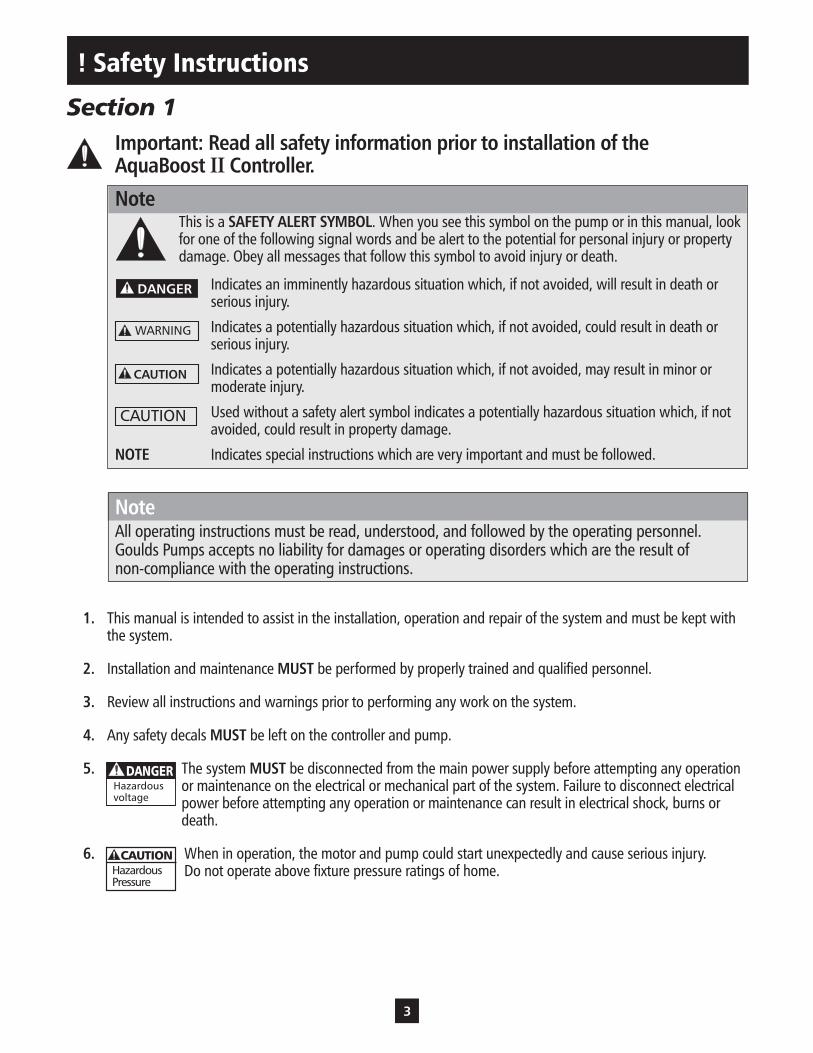
Section 1Important: Read all safety information prior to installation of the AquaBoost II Controller.
NoteThis is a SAFETY ALERT SYMBOL. When you see this symbol on the pump or in this manual, look for one of the following signal words and be alert to the potential for personal injury or property damage. Obey all messages that follow this symbol to avoid injury or death.
Indicates an imminently hazardous situation which, if not avoided, will result in death or serious injury.
Indicates a potentially hazardous situation which, if not avoided, could result in death or serious injury.
Indicates a potentially hazardous situation which, if not avoided, may result in minor or moderate injury.
Used without a safety alert symbol indicates a potentially hazardous situation which, if not avoided, could result in property damage.
NOTE Indicates special instructions which are very important and must be followed.
NoteAll operating instructions must be read, understood, and followed by the operating personnel. Goulds Pumps accepts no liability for damages or operating disorders which are the result of non-compliance with the operating instructions.
1. This manual is intended to assist in the installation, operation and repair of the system and must be kept with the system.
2. Installation and maintenance MUST be performed by properly trained and qualified personnel.
3. Review all instructions and warnings prior to performing any work on the system.
4. Any safety decals MUST be left on the controller and pump.
5. The system MUST be disconnected from the main power supply before attempting any operation or maintenance on the electrical or mechanical part of the system. Failure to disconnect electrical power before attempting any operation or maintenance can result in electrical shock, burns or death.
6. When in operation, the motor and pump could start unexpectedly and cause serious injury. Do not operate above fixture pressure ratings of home.
Hazardousvoltage
DANGER
HazardousPressure
CAUTION
CAUTION

4
System Compnents
Section 2Please review the AquaBoost II components and insure that you have all the parts and are familiar with their names. Be sure to inspect all components Goulds Pumps supplies for shipping damage.
AquaBoost II: (NOTE: STANDARD UNIT WILL COME WITH TRANSDUCER AND TRANSDUCER CABLE ONLY)1. Pump with 3 Phase Motor2. AquaBoost II Controller with Integral Pressure Sensor Cable (1AB2, 2AB2 or 3AB2)3. Pressure Tank (V6P or V15P)4. Pressure Sensor (9K336)5. Mounting Kit6. Tank Tee with Pipe Plug (AV20-6) 1" or (AV20-12) 1¼"7. Pressure Gauge (AG5 = 100 PSI Range, AG2 = 200 PSI Range)
WarningDO NOT power the unit or run the pump until all electrical and plumbing connections, especially the pressure sensor connection, are completed. The pump should not be run dry. All electrical work must be performed by a qualified technician. Always follow the National Electrical Code (NEC), or the Canadian Electrical Code (CEC) as well as all local, state and provincial codes. Code questions should be directed to your local electrical inspector. Failure to follow electrical codes and OSHA safety standards may
result in personal injury or equipment damage. Failure to follow manufacturer's installation instructions may result in electrical shock, fire hazard, personal injury, death, damage to equipment, unsatisfactory performance and may void manufacturer's warranty.
WARNINGHazardousvoltage
HazardousPressure
CAUTION

5
System Design
Section 3NoteSystems MUST be designed by qualified technicians only and meet all applicable state and local code requirements.
The following diagrams show a typical system using the AquaBoost II Constant Pressure System. Connection can be made directly to a water supply or water can be drawn from a supply tank. Diagram #1 shows a typical set up for a municipal water connection.
Diagram #2 shows a set-up for well feed, supply tank. This allows pump maintenance without main line shut-off.
Diagram 1System Layout for municipal hook-up
Diagram 2System Layoutfor supply tank
Home Supply Water Main
Check Valves
Isolation Valve
Unions
Check Valves
To Drain
ReliefValve
GaugeTank
AquaBoost Control
Circuit Breaker
Disconnect
Home Supply Well Supply
Check Valves
Isolation Valve
Unions
Check Valves
To Drain
ReliefValve
GaugeTank
AquaBoost Control
Circuit Breaker
Disconnect
AtmosphericStorage Tank
NOTE: NOT ALL FITTINGS, VALVES ARE INCLUDED IN AQUABOOST SYSTEMS.

6
Piping
Section 4General
NoteAll plumbing work must be performed by a qualified licensed technician. Always follow all local, state and provincial codes.
A proper installation requires a pressure relief valve, a ¼" female N.P.T. threaded fitting (found on tank tee) for the pressure sensor, and properly sized pipe. Piping should be no smaller than the pump discharge and/or suction connections. Piping should be kept as short as possible. Avoid the use of unnecessary fittings to minimize friction losses.
Some pump and motor combinations supplied with this system can create over 200 PSI. Select pipe and fittings accordingly per your pipe suppliers’ recommendation. Consult local codes for piping requirements in your area.
All joints must be airtight. Use Teflon tape or another type of pipe sealant to seal threaded connections. Please be careful when using thread sealant as any excess that gets inside the pipe may plug the pressure sensor and impeller.
Galvanized fittings or pipe should never be connected directly to the stainless steel discharge head or casing as galvanic corrosion may occur. Barb type connectors should always be double clamped.
Pressure Tank, Pressure Relief Valve and Discharge PipingThe standard Hydro-Pro tank has a pre-charge of 38 PSI. You may set the tank pre-charge anywhere between 10 PSI and 20 PSI below the system operating pressure. Use the higher tank pre-charge setting if the system drifts over 5 PSI at a constant flow rate. Use only “pre-charged” tanks on this system. Do not use galvanized tanks. Select an area that is always above 34º F (1.1º C) in which to install the tank and pressure relief valve. If this is an area where a water leak or pressure relief valve blow-off may damage property, connect a drain line to the pressure relief valve. Run the drain line from the pressure relief valve to a suitable drain or to an area where water will not damage property. Use the optional tank tee to connect the discharge pipe to the pressure tank and house plumbing. It is allowable to pump to multiple locations.
WarningMaximum working pressure of the Goulds HydroPro tank is 125 psi. Do not exceed pressure ratings of household fixtures.
Pressure Tank Installation and SelectionEXPLODING TANK CAN INJURE OR KILL.
Refer to pump catalog or contact your supplier for maximum discharge pressure of pump. Ensure pressure rating of pipe is greater than maximum discharge pressure of pump.
It is likely that the pressure relief valve will open sometime during the life of the system. Plan ahead by running drain to a location where water will not cause damage.
Diaphragm Tank Sizing and Pre-Set Pressure Recommendations:Diaphragm type (captive air) tanks are required on these systems.Total Tank Volume, not drawdown volume, is used to select the proper tank size. The total tank volume should be approximately 20% of the pump’s maximum flow. For example, when using a 10 gpm pump the system requires a
HazardousPressure
CAUTION
WARNING
CAUTION

7
WARNINGHazardousvoltage
HazardousPressure
CAUTION
Piping
2 gallon (total volume) tank, i.e. a V6P or TP6P. A 50 gpm pump requires a minimum 10 gallon total volume tank, a V25 at 8.2 gallons may be too small, in this case we recommend the next larger tank, a V45 or TP45 at 13.9 gallons. Due to the many variables in a pump system there may be installations where a smaller than recommended tank will operate the system properly. The tank sizing recommendations are field proven to prevent objectionable pressure drops on start-up and provide smooth operation for the majority of variable speed pump systems.Set the tank pressure, while tank is empty of water, to 20 psi below the desired system pressure setting. Ex. for a 50 psi system pressure, charge the tank to 30 psi. Tanks sold by ITT Water Products brands are all factory pre-charged to 38 psi. Locate the tank where it will not freeze.
Installing the Pump
WarningRisk of electric shock - This pump system has not been investigated for use in swimming pool areas.
Plumb suction and discharge of pump into piping. Be sure to install a check valve on the suction side of the pump. Use a minimum of 6 inches of straight pipe between the check valve and the suction of the pump. Locate the pump as near liquid source as possible. When pumping out of an atmospheric
tank locate the pump below the level of the liquid in the tank. All piping must be supported independently of the pump. Be sure that suction and discharge piping are in line with the suction and discharge of the pump. For additional information refer to Installation, Operation and Maintenance Instructions supplied with the pump.
NoteIf pump is drawing water from a storage tank, a flapper type check valve may be necessary, instead of spring loaded valve on suction side of pump.
Installing the Pressure SensorInstall the pressure sensor in the tank tee provided with the unit. The pressure sensor cable supplied with the controller is 80 inches long and is pre-wired to the Aquaboost controller. Locate the controller so there will be enough cable to properly install the pressure sensor. Do not install in temperatures below 32ºF. Freezing will damage transducer.
CautionDo not install any shut-off valves, filters or flow/pressure control devices between the pres-sure sensor and the discharge of the pump as this could create a hazardous situation.
Use ONLY the pressure sensor provided with the unit. Install the pressure sensor into one of the ¼" holes on the tank tee provided in the kit. Do not install the pressure sensor upside down. Do not install the tank tee with the ¼" holes facing down. Align the connector on the end of the pressure sensor cable with the mating connector on the pressure sensor and push it on. The tab will lock it in place. Maximum recommended transducer cable length is 100'. Order number PSC1200, if required.
HazardousPressure
CAUTION
HazardousPressure
CAUTION

8
WARNINGHazardousvoltage
Mounting the Controller
Section 5General
Mount the controller in a well ventilated, shaded area using the supplied mounting kit. The controller must be mounted vertically. Be sure to leave 8 inches of free air space on every side of the unit. The controller must be in an area with an ambient between 0º F and 122º F.
NoteDo not block the heat sink (fins) and do not set anything on the units.
WarningThe controller access cover should always be securely fastened to the control box due to the dangerous voltage/shock hazard inside the unit.
Section 6Power Supply
The controller requires a single-phase power supply of 230 volts +/- 15% on a dedicated 30-amp two-pole circuit breaker. A dedicated circuit means no other appliances use the same circuit! The output power from the motor controller is three-phase, variable frequency and variable voltage.
Maximum output voltage and frequency are line input voltage and 60 Hz, respectively. Low supply voltage will reduce pump performance.
NoteInstallation and maintenance MUST be performed by properly trained and qualified personnel. Always follow the National Electric Code or Canadian Electric Code, as well as all local, state and provincial codes when wiring the system.
Wire and ConduitFactory installed input and output power leads may be supplied with the controller. Use 90ºC UL type copper wire. Use of Metal Conduit with Metal Conduit liquid tight Connectors is recommended for all electrical connections.
Connecting Input Power Connect the 230 volt, single-phase power supply leads and Safety Ground wire from a 30 amp two-pole circuit breaker (in the OFF position) to one side of a 30-amp two-pole disconnect switch. Connect the input power leads supplied with the controller to the other side of the disconnect switch. Be sure to use Metal Conduit with Metal Conduit Connectors for electrical connections. Use min 10 AWG copper wire. 90ºC UL rated.
Hazardousvoltage
DANGER

9
Starting the System
Hazardousvoltage
DANGER
DangerThe controller has a high leakage current to ground. The terminals marked "GND" in the controller must be connected to the safety ground from the electrical service entrance. Failure to properly ground the controller or motor will create an electrical shock hazard.
NoteDo not use GFCI protection with this controller. Nuisance tripping will result.
Motor Power ConnectionsConnect the motor leads for 230 volt, 200 volt, or 208 volt operation using the nameplate as a reference. Connect the output power leads from the controller to the 3 motor leads in the conduit box on the motor. Connect the ground (green) output power lead to the ground screw
in the conduit box on the motor. This step is performed in its entirety at the factory for complete systems. See diagram 4 for details. Use minimum 14 AWG copper wire. 90ºC UL rated.
NoteIf the pump has more than 50 feet of wire from the controller, consult factory for selection of an output load filter (load reactor).
Section 7Danger
Status Code Indicator Light is not a voltage indicator! Always turn off disconnect switch and circuit breaker before servicing.
DangerOnce the controller is powered it will remain electrically charged for 5 minutes after power is turned off. Wait 5 minutes after disconnecting power before opening con-troller access cover as there is a severe shock hazard.
Setting the Motor Overload SwitchThe Motor Overload Setting Switches adjust the level of motor overload current protection needed to protect the motor from damage due to overcurrent conditions. Turn the circuit breaker and disconnect switch to the off position, and wait 5 minutes. Remove controller access cover. Read the Service Factor Amps off the motor nameplate. Match the Service Factor Amps (SF Amps) of the motor to the correct switch setting. See Section 8 for details. Set the Motor Overload Switch according to the correct setting. If the Service Factor Amps of the motor does not match any of the Motor Overload Settings, use the next lowest switch setting.
Hazardousvoltage
DANGER
Hazardousvoltage
DANGER
Hazardousvoltage
DANGER
Figure A
10
Starting the System
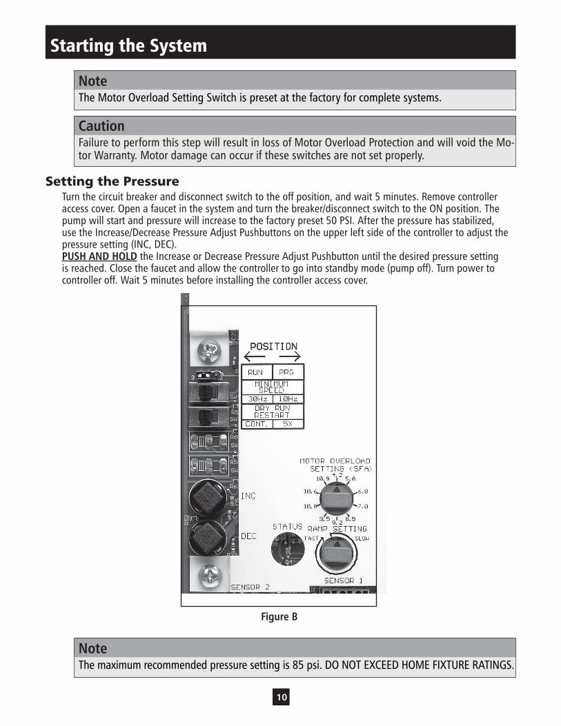
NoteThe Motor Overload Setting Switch is preset at the factory for complete systems.
CautionFailure to perform this step will result in loss of Motor Overload Protection and will void the Mo-tor Warranty. Motor damage can occur if these switches are not set properly.
Setting the PressureTurn the circuit breaker and disconnect switch to the off position, and wait 5 minutes. Remove controller access cover. Open a faucet in the system and turn the breaker/disconnect switch to the ON position. The pump will start and pressure will increase to the factory preset 50 PSI. After the pressure has stabilized, use the Increase/Decrease Pressure Adjust Pushbuttons on the upper left side of the controller to adjust the pressure setting (INC, DEC).PUSH AND HOLD the Increase or Decrease Pressure Adjust Pushbutton until the desired pressure setting is reached. Close the faucet and allow the controller to go into standby mode (pump off). Turn power to controller off. Wait 5 minutes before installing the controller access cover.
NoteThe maximum recommended pressure setting is 85 psi. DO NOT EXCEED HOME FIXTURE RATINGS.
Figure B

11
NoteBefore adjusting the Minimum Frequency or Ramp Setting Switches, turn the circuit breaker and disconnect switch to the off position. Wait 5 minutes. Remove the controller access cover. See Section 8 for details.
Setting the Minimum Frequency SwitchThe controller has 2 possible Application Settings. These settings are used to adjust the Minimum Speed of the motor. This allows the controller to fit a wide range of applications. Select a Minimum Speed of 10 Hz if the pressure at the pump’s suction is within 20 PSI of the desired pressure setting. Select a Minimum Speed of 30Hz if the pressure at the pump’s suction is more than 20 PSI below the desired pressure setting, if pumping from a tank or if drawing a suction lift.
Setting the Ramp SettingChanging the Ramp Setting changes how fast the controller can change the speed of the motor. A Slow Ramp Setting allows the controller to work better in applications where the average demand for water is low (less than 3GPM or about 1 faucet). A Fast Ramp Setting allows the controller to work better in applications where the demand for water is high because the motor is allowed to change speed faster.
NoteThe Ramp Setting is preset at the factory for the “6 O‘Clock” position which is a half way point between fast and slow. If “Hunting” or pressure fluctuation occurs, turn dial to slower setting.
Motor Rotation DirectionIf the pressure or flow seems low, check motor rotation direction. Turn the circuit breaker and disconnect switch to the off position, and wait 5 minutes. Switch any two leads on the controller output (T1, T2, or T3). Turn the circuit breaker and disconnect switch to the on position. Observe pressure and flow. If pressure or flow still seems low check plumbing. When viewing motor shaft end, rotation should be clockwise.
NoteIt is possible for the pump to maintain constant pressure with a low flow or a high positive suction head even if the pump is rotating backwards. While the pump is running, use an amp probe on one of the output power leads connected to the motor and compare the current draw between the two rotation directions. The lowest current reading indicates the pump is running in the correct direction.
System StatusThe controller is always powered. A Solid Green Status Code indicates that the pump is in standby mode (pump not running) or that the line input voltage is low.
DangerStatus Code Indicator Light is not a voltage indicator! Always turn off disconnect switch and circuit breaker and wait 5 minutes before servicing.
A Blinking Green Status Code indicates that the pump is running. A Blinking or Solid Red Light indicates a problem with the controller. Refer to the front cover or Diagram 5 for Status Codes. See Section 9 for more details on fault codes.
Starting the System
Hazardousvoltage
DANGER
12
Diagrams
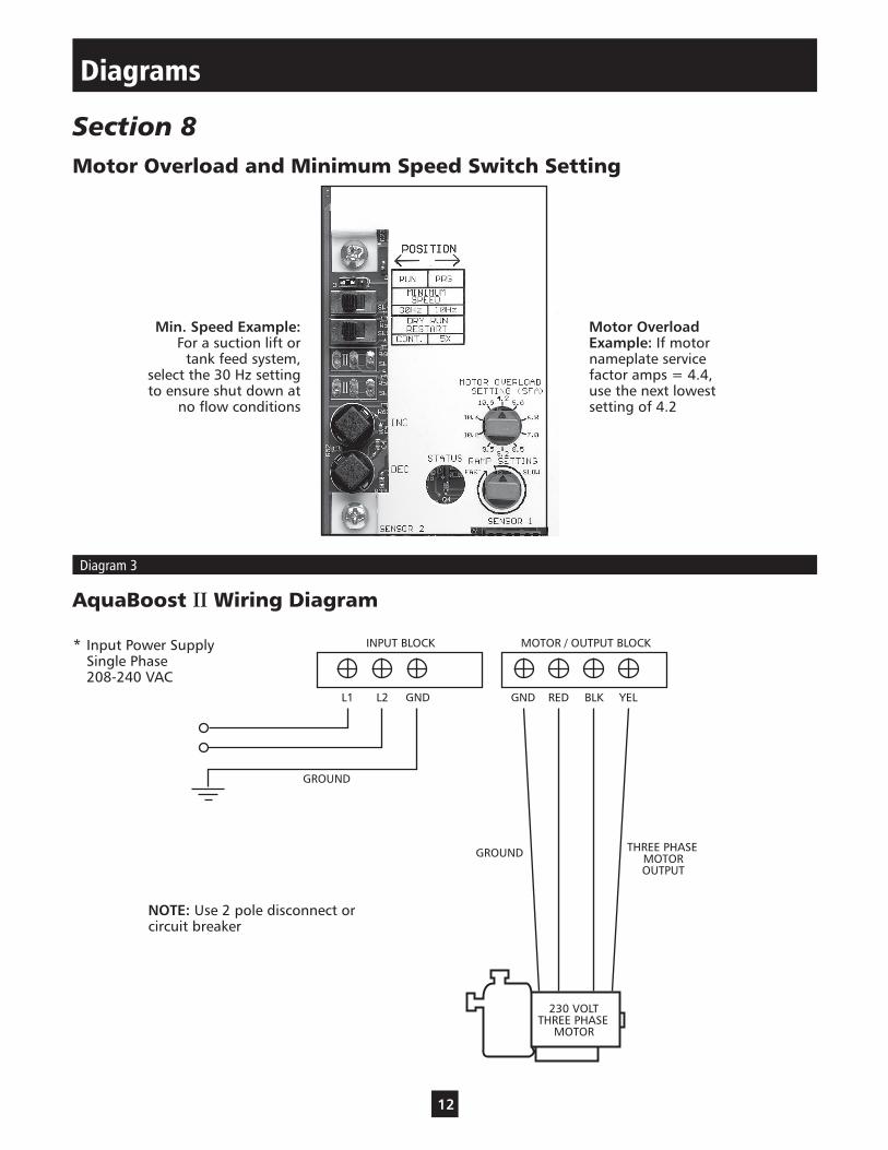
Section 8Motor Overload and Minimum Speed Switch Setting
AquaBoost II Wiring Diagram
Diagram 3
Motor Overload Example: If motor nameplate service factor amps = 4.4, use the next lowest setting of 4.2
Min. Speed Example: For a suction lift or
tank feed system, select the 30 Hz setting to ensure shut down at
no flow conditions
INPUT BLOCK MOTOR / OUTPUT BLOCK
L1 L2 GND GND RED BLK YEL
GROUND
THREE PHASEMOTOROUTPUT
GROUND
230 VOLTTHREE PHASE
MOTOR
NOTE: Use 2 pole disconnect or circuit breaker
* Input Power Supply Single Phase 208-240 VAC
13
Diagram 4
Diagrams
Section 8 (continued)
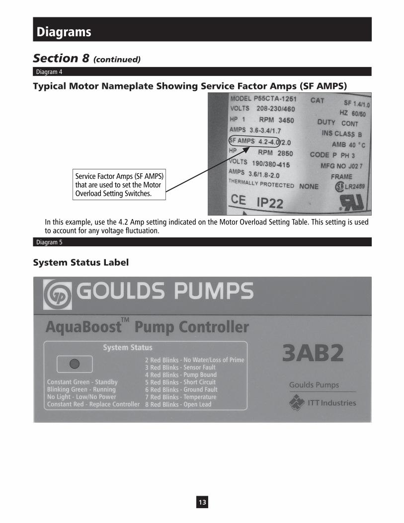
Typical Motor Nameplate Showing Service Factor Amps (SF AMPS)
In this example, use the 4.2 Amp setting indicated on the Motor Overload Setting Table. This setting is used to account for any voltage fluctuation.
System Status Label
Diagram 5
Service Factor Amps (SF AMPS) that are used to set the Motor Overload Setting Switches.

14
Hazardousvoltage
DANGER
Troubleshooting
Section 9General
The AquaBoost II is a self-diagnosing controller. If a problem occurs, observe the Status Code Indicator Light on the front of the unit. No Status Code Indicator Light means either no or low input voltage (less than 50 V).
DangerStatus Code Indicator Light is not a voltage indicator! Always turn off disconnect switch and circuit breaker and wait 5 minutes before servicing. High voltage may still remain on controller.
Refer to the status code label on the front of the controller access cover to diagnose system errors. See Diagram 6 for details.
Use the following table to help troubleshoot problems.
NOTE: ALWAYS TROUBLESHOOT THE FOLLOWING FIRST:
1. Input supply power is within limits. Low voltage will cause lower performance.
2. Fuses are intact.
3. Circuit breaker is not tripped or overheating. Is it sized correctly?
4. Motor leads are connected for 230 volt, 3 phase?
5. All ground leads are connected?
6. Motor insulation or lead short / damage.
7. Pump is rotating in correct direction.
8. Pump is not jammed or blocked.
9. Transducer is located correctly in piping.
10. Check valve is located before tank and transducer.
15
Troubleshooting
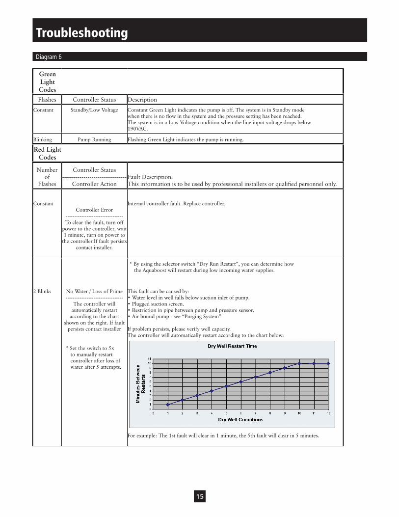
Green Light CodesFlashes Controller Status Description
Constant
Standby/Low Voltage
Constant Green Light indicates the pump is off. The system is in Standby mode when there is no flow in the system and the pressure setting has been reached. The system is in a Low Voltage condition when the line input voltage drops below 190VAC.
Blinking Pump Running Flashing Green Light indicates the pump is running.
Red Light Codes
Number of
Flashes
Controller Status ---------------------------------
Controller ActionFault Description. This information is to be used by professional installers or qualified personnel only.
Constant
Controller Error --------------------------------- To clear the fault, turn off
power to the controller, wait 1 minute, turn on power to
the controller.If fault persists contact installer.
Internal controller fault. Replace controller.
2 Blinks
No Water / Loss of Prime ---------------------------------
The controller will automatically restart
according to the chart shown on the right. If fault
persists contact installer
This fault can be caused by: • Water level in well falls below suction inlet of pump. • Plugged suction screen. • Restriction in pipe between pump and pressure sensor. • Air bound pump - see “Purging System” If problem persists, please verify well capacity. The controller will automatically restart according to the chart below: For example: The 1st fault will clear in 1 minute, the 5th fault will clear in 5 minutes.
Diagram 6
* Set the switch to 5x to manually restart controller after loss of water after 5 attempts.
* By using the selector switch “Dry Run Restart”, you can determine how the Aquaboost will restart during low incoming water supplies.

16
3 Blinks
Sensor Fault ---------------------------------
The controller will not run if the signal from the sensor
is disconnected or out of tolerance. The controller will automatically restart when the signal is within tolerance. If fault persists
contact installer.
This fault can be caused by: • Disconnected sensor. Disconnect sensor from sensor cable connector and reconnect to ensure a good connection. • Disconnected sensor cable lead inside the controller. Check for loose wires where the sensor cable connects to the circuit board by tugging on each wire. • Broken wire in the sensor cable. • Miswired sensor cable. Check that the wires are connected to the correct terminals on the sensor connector. The correct location of the wires is indicated on the circuit board. B=Black, R=Red, W=White. • Failed sensor. With the sensor cable connected to the circuit board, measure the DC voltage between the black and white wires of the sensor cable at the sensor connector, as shown below. The voltage measured should be between 0.5Vdc and 4.5Vdc.
4 Blinks
Pump or Motor Bound
--------------------------------- The controller will try to
restart the motor three times before displaying this fault. To clear the fault, turn off
power to the controller, wait 1 minute, turn on power to the controller. If fault persists contact installer.
This fault can be caused by: • Mechanical binding from debris in pump. • Electrical failure of the motor. • Incorrect setting of “Motor Type” switch. Verify the error by turning power to controller off for 1 minute and then on. Pump/Motor must be checked if fault persists.
Table 3: Fault Blink Codes (continued from previous page)
Troubleshooting

17
Table 3: Fault Blink Codes (continued from previous page)
6 Blinks
Ground Fault ---------------------------------
The controller will not restart if displaying this
fault. To clear the fault, turn off power to the controller,
wait 1 minute, turn on power to the controller. If fault persists contact
installer.
This fault can be caused by: • Electrical failure of the motor • Electrical failure of wiring between controller and motor. • Miswiring of motor cable. Verify the error by turning power to controller off for 1 minute and then on. If error persists, motor and wiring between controller and motor must be checked. Turn power off and wait 1 minute. Remove the three motor wires and ground wire from the terminal block. Check wiring and motor for shorting phase to ground using a megohmmeter (“megger”). A reading less than 200K Ohms indicates faulty insulation in the motor cable or motor. Test each to determine fault location.
7 Blinks
Temperature ---------------------------------
The controller will automatically restart when the temperature reaches
an acceptable level. If fault persists contact installer.
This fault can be caused by: • High ambient temperature. The maximum ambient temperature rating is 122ºF (50ºC). • Low ambient temperature. The minimum ambient temperature rating is -4ºF (-20ºC). Check for a fan failure. The fan will turn on when the temperature inside the controller reaches 140ºF (60ºC). The fan will turn on for 1 second each time the controller starts the motor. If the fan never turns on, check fan connections and replace as needed. Ensure that the external fan intake filter is not blocked or clogged. It can be removed for cleaning and replacements are available.
8 Blinks
Open Lead ---------------------------------
The controller will not restart if displaying this
fault. To clear the fault, turn off power to the controller,
wait 1 minute, turn on power to the controller. If fault persists contact
installer.
This fault can be caused by: • Disconnected or broken wire between the controller and motor. Verify the error by turning power to controller off for 1 minute and then on. If error persists, motor and wiring between controller and motor must be checked. Turn power off for 1 minute. Remove the three motor wires from the terminal block. Using an ohmmeter, measure the resistance from phase to phase. A disconnected or broken wire will be indicated by a high resistance reading (20 Ohms or higher).
5 Blinks
Short Circuit --------------------------------- If this fault was detected
while the pump was running, the controller will
attempt to restart three times before displaying this fault. To clear the fault, turn off
power to the controller, wait 1 minute, turn on power to the controller. If fault persists contact installer.
This fault can be caused by: • Electrical failure of the motor • Electrical failure of wiring between controller and motor. Verify the error by turning power to controller off for 1 minute and then on. If error persists, motor and wiring between controller and motor must be checked. Turn power off for 1 minute. Remove the three motor wires from the terminal block. Check wiring and motor for shorting phase to phase and phase to ground. 230V motor typical phase-phase resistances: .5 HP = 10 Ohms, .75 HP = 7 Ohms, 1 HP = 5 Ohms, 1.5 HP = 3.5 Ohms, 2 HP = 2.5 Ohms, 3 HP = 2 Ohms, 5 HP = 1 Ohm, 7.5 HP = .75 Ohms, 10 HP = .5 ohms
Troubleshooting
18
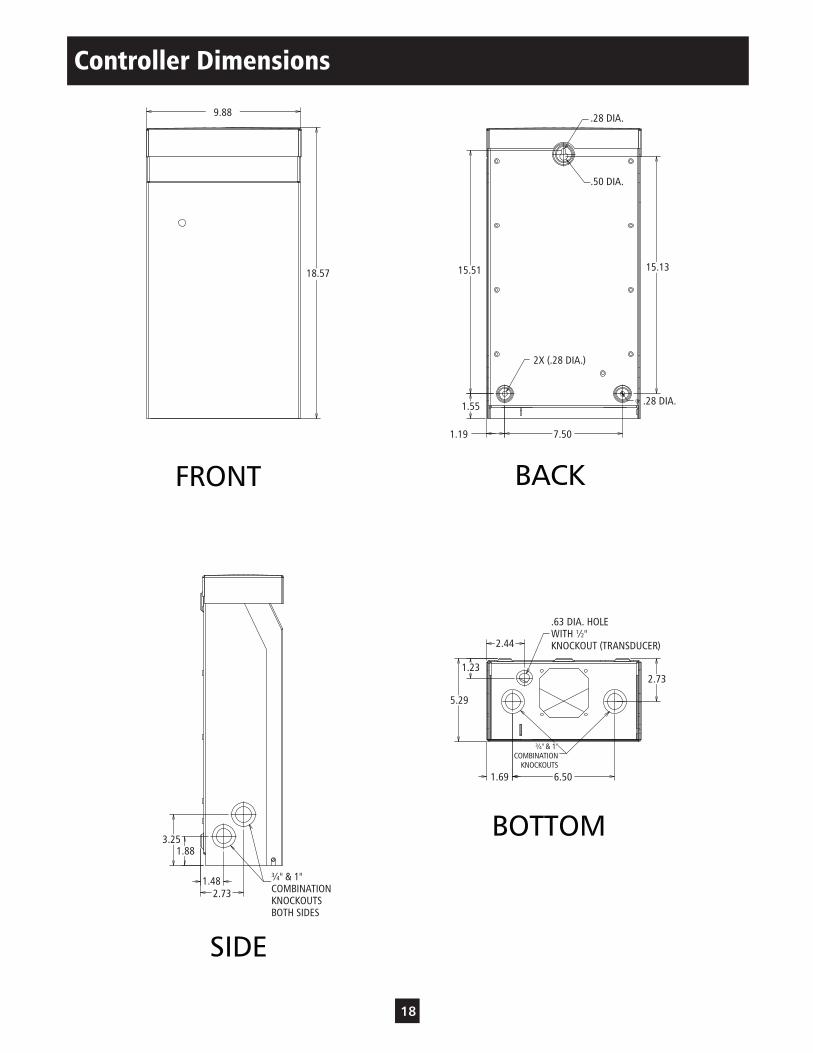
Controller Dimensions
3/4" & 1"COMBINATION
KNOCKOUTS
3/4" & 1"COMBINATIONKNOCKOUTSBOTH SIDES
ÿ HOLEWITH 1/2"KNOCKOUT (Transducer)
.63
( )18.57
( )7.50
( )1.23
( )5.29
( )9.88
( )1.19
( )2.73
( )1.69 ( )6.50
( )2.44
( )15.13( )15.51
( )1.55
( )1.88
( )3.25
( )1.48
( )2.73
2X (ÿ ).28
(ÿ ).28
(ÿ ).50
(ÿ ).28
FRONT BACK
SIDE
BOTTOM
9.88
18.57
3.251.88
1.482.73
¾" & 1"COMBINATIONKNOCKOUTSBOTH SIDES
5.29
¾" & 1"COMBINATION
KNOCKOUTS
6.501.69
1.232.73
2.44
.63 DIA. HOLEWITH ½"KNOCKOUT (TRANSDUCER)
7.501.19
1.55
15.51 15.13
.28 DIA.
2X (.28 DIA.)
.50 DIA.
.28 DIA.

19
Notes

20© 2005 ITT Water Technology, Inc.Effective April, 2005Printed in USA
GOULDS PUMPS LIMITED WARRANTYThis warranty applies to all AquaBoost and AquaBoost II systems manufactured by Goulds Pumps.Any part or parts found to be defective within the warranty period shall be replaced at no charge to the dealer during the warranty period. The warranty period shall exist for a period of twelve (24) months from date of installation or eighteen (30) months from date of manufacture, whichever period is shorter.A dealer who believes that a warranty claim exists must contact the authorized Goulds Pumps distributor from whom the pump was purchased and furnish complete details regarding the claim. The distributor is authorized to adjust any warranty claims utilizing the Goulds Pumps Customer Service Department.The warranty excludes:(a) Labor, transportation and related costs incurred by the dealer;(b) Reinstallation costs of repaired equipment;(c) Reinstallation costs of replacement equipment;(d) Consequential damages of any kind; and,(e) Reimbursement for loss caused by interruption of service.For purposes of this warranty, the following terms have these definitions:(1) “Distributor” means any individual, partnership, corporation, association, or other legal relationship that stands between Goulds Pumps and the dealer in purchases, consignments or contracts for sale of the subject pumps.(2) “Dealer” means any individual, partnership, corporation, association, or other legal relationship which engages in the business of selling or leasing pumps to customers.(3) “Customer” means any entity who buys or leases the subject pumps from a dealer. The “customer” may mean an individual, partnership, corporation, limited liability company, association or other legal entity which may engage in any type of business.
THIS WARRANTY EXTENDS TO THE DEALER ONLY.
www.goulds.com
Goulds Pumps is a brand of ITT Water Technology, Inc. – a subsidiary of ITT Industries, Inc.
Goulds Pumps, AquaBoost II and the ITT Engineered Blocks Symbol are registered trademarks and tradenames of ITT Industries.