Embed Size (px)
Citation preview

Aqualvalve 700 Thermo installation instuctions page 1
Aquavalve 700®
Thermoshower valve

Aqualvalve 700 Thermo installation instuctions page 2
Aquavalve 700 ThermoExposed valve
Chrome
700.51.01Gold
700.51.04
Aquavalve 700 ThermoConcealed valve
Chrome
700.50.01Gold
700.50.04
Shower systems
Aqualvalve 700 Thermo installation instuctions page 3
Components
Components (exposed)
Components (concealed)
Literature not shown.
Literature not shown.

Aqualvalve 700 Thermo installation instuctions page 4
Important information
IntroductionThe Aquavalve 700 Thermo is a brass bodied thermostatic shower valve designed for built in and concealed panel mount and
exposed installations. The Aquavalve 700 Thermo provides close temperature stability and fail safe protection when installed
on approved gravity or pumped systems and balanced high pressure systems. A cold inlet flow regulator is provided for use
with instantaneous (multipoint) gas water heater and combination boiler applications.
If you have any questions at any stage during installation please contact the Aqualisa customer helpline on 01959 560010 for advice.
Commercial applicationsThis product is suitable for commercial applications. Products BBV001 (exposed) and BBV002 (concealed) should be ordered.
The BBV001 is fitted with the ⁄÷™” outlet at the top of the valve to facilitate the use of an exposed fixed head, rather than at
the bottom of the valve as per the domestic 700.51.01 version.
Safety informationThis product must be installed by a competent person in accordance with all relevant current Water Supply Regulations.
FlushingSome modern fluxes can be extremely corrosive and, if left in contact, will attack the working parts of this unit. All soldering
must be completed and the pipe work thoroughly flushed out in accordance with current Water Supply Regulations prior
to connection of the product.
ConnectionsThe Aquavalve 700 Thermo is supplied for connection to conventional supplies with HOT on the LEFT and COLD on the RIGHT
when viewed from the front. However, for non-conventional supplies, the valve can be reversed by 180º. Please see installation
instructions overleaf to reverse the valve.
The Aquavalve 700 Thermo exposed valve is supplied complete with 15mm compression elbow fittings at 198mm centres. The
Aquavalve 700 Thermo concealed valve is not supplied with any elbow connections. Suitable ‹÷¢” BSP union connections will
need to be used.
Pipe work connections to this product should be cut using a rotary type cutter.
Isolating valvesSuitable isolation valves such as gate valves must be fitted to both supplies in accordance with the current Water Supply
Regulations and our terms of warranty.
Due to their restrictive characteristics, stopcocks and ball type valves that reduce the pipe bore size must not be used on gravity
or pumped installations.
FiltersTo ensure ongoing optimum performance the internal control mechanism ‘cartridge’
is protected by a two-part filter system. Debris accumulation may result in reduced
flow from the shower head and noisy operation.
As this condition is not covered by our standard warranty terms, it is suggested that
the cartridge be removed and the filters checked by a competent person. In the event
of any difficulties please contact the Aqualisa customer helpline for assistance.
SitingFor optimum performance, with gravity fed systems, the distance between the bottom of the storage cistern and the shower
head should not be less than 1m (when using an adjustable height shower head). If using a fixed head, the highest point of
the pipe work must be not less than 1m below the underside of the cistern. Please refer to the system layouts on the reverse of
this guide.
Aqualvalve 700 Thermo installation instuctions page 5
Important information
Pump installationUNDER NO CIRCUMSTANCES MUST A PUMP BE FITTED DIRECTLY TO THE WATER MAIN.
A pump must only be used to boost the pressure from tank-fed supplies. A typical layout is shown on the reverse of this guide.
Stored water capacitiesThe minimum capacity of the cold storage cistern should not be less than 225 litres (50 gallons). The capacity of the hot cylinder must be
capable of meeting the anticipated demand.
PressuresThe Aquavalve 700 Thermo shower valve is designed to control static pressure up to 10 bar. Where pressures are likely to exceed 10 bar, a
pressure reducing valve (PRV) must be fitted into the incoming mains supply. A setting of 3 bar is recommended. It should be noted that
daytime pressures approaching 8 bar can rise above the stated maximum overnight.
The Aquavalve 700 Thermo is not suitable for mixed supply systems e.g. gravity hot and mains cold.
A suitable PRV is available from Aqualisa.
Gravity fed hot and cold suppliesServices must be installed according to good plumbing practice having regard to pipe sizing, long pipe runs and low-head situations.
The cold supply for the valve assembly must be taken directly from the cold storage system. The hot supply may be taken from the
vent/draw off pipe of the hot water cylinder at a point below the cylinder connection or alternatively from the underside of the horizontal
draw off.
Rising pipe work must not be connected into the horizontal draw-off from the cylinder or to any point in the vent/draw off pipe above the
cylinder connection.
CYLINDER TEMPERATURE IN EXCESS OF 65ºC MAY RESULT IN POOR SHOWER PERFORMANCE.
To minimise pressure loss we recommend that the hot and cold supplies are run in 22mm as close as reasonably possible to the mixing
valve before reducing to 15mm.
A typical layout is shown on the reverse of this guide.
Balanced high-pressure systemThe Aqualisa Thermo cartridge is designed to operate with unvented hot water storage systems up to a maximum pressure of 10 bar. A
PRV must be used if either supply exceeds 10 bar. The cold water supply must be drawn from the same mains supply as that to the hot
water system (down stream of the cylinder manufacturers pressure limiting valve, where supplied) and the hot supply from the nearest
convenient draw off point. Account must be taken of pressure drops that may occur when other draw-off points are used while the shower
is in use.
Pipe work can generally be run in 15mm.
Combination boiler/multipoint systemThe gas water heater must be capable of raising the temperature of the incoming water by 35ºC and delivering a flow rate of no less than
9 litres (2 gallons) per minute to the shower valve. This is sufficient to operate one outlet point at a time. The Aqualisa Thermo cartridge is
designed to operate from the mains at a maximum of 10 bar. If the mains pressure exceeds 10 bar a ‘drop tight’ PRV must be fitted on
the supply pipe after the main stopcock.
The cold supply can be taken from the nearest convenient mains supply and the hot supply can be taken from the nearest hot water draw-
off point. Account must be taken of the pressure drops that will occur when other draw-off points are used while the shower is in use.
Pipe work can generally be run in 15mm.

Aqualvalve 700 Thermo installation instuctions page 6
Step -by-step instructions
In addition to the guide below it is essential that the written instructions
overleaf are read and understood and that you have all the necessary
components (shown overleaf) before commencing installation. Failure to
install the product in accordance with these instructions may adversely
affect the warranty terms and conditions. Do not undertake any part of this
installation unless you are competent to do so. Prior to starting ensure that
you are familiar with the necessary plumbing regulations required to install
the product correctly and safely.
The Aquavalve 700 Thermo is supplied with universal fittings.
Please note that the fixing template is supplied as a guide only, we thus
recommend that you assemble the valve and measure the pipe inlet
centres against the template prior to installation.
Carefully cut out the cardboard fixing
template supplied, mark out the inlet supply
holes at 194mm centres.
1
Exposed valve
Rear entry pipe work
Set the pipe work to emerge from the wall at right angles.2
Make good the wall as appropriate. After making good, measure the pipes
and mark the pipe cut off length (19mm-21mm).3
!
!
4 Remove the mounting ring from the rear of
the valve using the 2.5mm
hexagonal key provided. Locate the ring
inside the large ring on the template ensur-
ing the locking screw is in the 6 o’clock
position and mark the four fixing
holes.
Aqualvalve 700 Thermo installation instuctions page 7
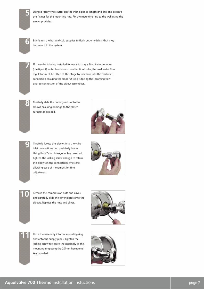
Using a rotary type cutter cut the inlet pipes to length and drill and prepare
the fixings for the mounting ring. Fix the mounting ring to the wall using the
screws provided.
5
Briefly run the hot and cold supplies to flush out any debris that may
be present in the system.6
If the valve is being installed for use with a gas fired instantaneous
(multipoint) water heater or a combination boiler, the cold water flow
regulator must be fitted at this stage by insertion into the cold inlet
connection ensuring the small ‘O’ ring is facing the incoming flow,
prior to connection of the elbow assemblies.
7
Carefully locate the elbows into the valve
inlet connections and push fully home.
Using the 2.5mm hexagonal key provided,
tighten the locking screw enough to retain
the elbows in the connections whilst still
allowing ease of movement for final
adjustment.
9
Remove the compression nuts and olives
and carefully slide the cover plates onto the
elbows. Replace the nuts and olives.
10
Carefully slide the dummy nuts onto the
elbows ensuring damage to the plated
surfaces is avoided.
8
Place the assembly into the mounting ring
and onto the supply pipes. Tighten the
locking screw to secure the assembly to the
mounting ring using the 2.5mm hexagonal
key provided.
11

Aqualvalve 700 Thermo installation instuctions page 8
Carefully cut out the cardboard fixing
template provided, mark out the position
of the mouting ring. If required the
(194mm) inlet pipe centres may be used as
a guide to mark out the falling or rising
exposed pipework as appropriate to aid the
positioning of the pipe fixing clip locations.
1
Surface sited pipe work
Tighten the elbow locking screws using
2.5mm key provided. Slide the dummy nuts
into position and rotate them so the locking
screw is out of site before securing them
using the 2.5mm key.
Tighten the inlet compression unions sufficiently to ensure a watertight seal.
Push the cover plates over the unions flush to the wall surface.
12
13
After checking that the badge recess in the
on/off knob is clean, dry and free of dust,
remove the paper backing from the badge a
push firmly into position.
14
Drill and prepare the fixings for the
mounting ring. Fix the mounting ring to the
wall using the screws provided.
3
Remove the mounting ring from the rear of the valve using the 2.5mm
hexagonal key provided. Locate the ring inside the pre marked position,
ensuring the locking screw is in the 6 o’clock position and mark the four
fixing holes.
2

Aqualvalve 700 Thermo installation instuctions page 9
Concealed valve
Follow steps 6 to 14 listed above.4
In addition to the guide below it is essential that the written instructions
overleaf are read and understood and that you have all the necessary
components (shown overleaf) before commencing installation. Failure to
install the product in accordance with these instructions may adversely affect
the warranty terms and conditions. Do not undertake any part of this
installation unless you are competent to do so. Prior to starting ensure that
you are familiar with the necessary plumbing regulations required to install
the product correctly and safely.
The Aquavalve 700 is supplied with universal fittings.
Elbow connections are not supplied with concealed models; suitable ‹÷¢” BSP
unions are required.
!
If installing the product built in to a solid wall, chase out a suitable recess in
the wall to receive the valve and pipe work. If installing the valve in a
concealed panel mounted situation, in most cases it will be necessary to first
install a suitable sound fixing in the cavity area before fixing the valve.
A hole of Ø130mm is required to install the valve and gain access to inlet
and outlet connectors.
1
Minimum mounting depth 68mm,
maximum depth 82mm, measured
from mounting surface to
finished/tiled wall surface.
!
Unscrew the fixing screw and remove the
on/off knob. Set the temperature lever to
the vertical position, undo the four screws
and remove the temperature lever.
2
Remove the mounting ring from the shower
valve using the 2.5mm key provided.3
!
Min 68mm68mmMax 82mm82mm

Aqualvalve 700 Thermo installation instuctions page 10
Using suitable ‹÷¢” BSP unions, connect the inlet and outlet pipes.7
If the valve is being installed for use with a gas fired instantaneous
(multipoint) water heater or a combination boiler, the cold water flow
regulator must be fitted at this stage by insertion into the cold inlet
connection ensuring the small ‘O’ ring is facing the incoming flow,
prior to connection of the elbow unions.
6
Insert the valve into the mounting ring and
tighten the locking screw using the 2.5mm key
provided.
5
Turn on the supplies and check for any leaks upstream of the valve. Fit the
on/off knob and turn the shower valve on to check for any leaks downstream
of the valve. If all is sound, turn the shower valve off by turning the on/off
knob off fully clockwise. Remove the on/off knob and turn off the supplies.
8
Fill in the chase ensuring the valve body, elbows and outlet are not cemented
into the wall. Suitable non-setting infill material such as paper, polystyrene
etc. should be wrapped around the components and a plaster finish applied.
9Aqualisa reserves the right to revoke the terms of the warranty should access
to service connections be denied by the use of solid setting infill material.!
Using a silicone based lubricant or liquid
soap, lubricate the wall plate grommet
and push onto the valve flush with the wall
surface. A thin bead of silicone based
sealant may be required to seal the wall
plate to the wall surface.
10
Position the mounting ring in the chase or
suitable sound fixing surface. Ensure the
locking screw is in the 6 o’clock position and
mark the four fixing holes. Prepare the holes
and secure the mounting plate to the wall
using the fixings provided.
4
Aqualvalve 700 Thermo installation instuctions page 11
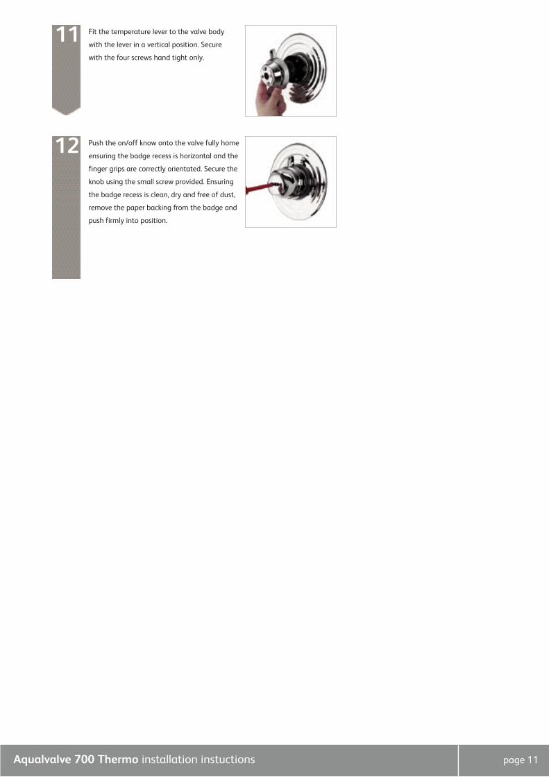
Fit the temperature lever to the valve body
with the lever in a vertical position. Secure
with the four screws hand tight only.
11
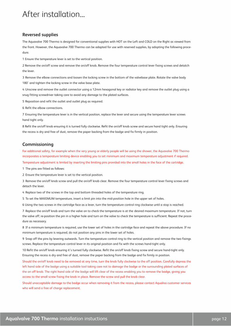
Push the on/off know onto the valve fully home
ensuring the badge recess is horizontal and the
finger grips are correctly orientated. Secure the
knob using the small screw provided. Ensuring
the badge recess is clean, dry and free of dust,
remove the paper backing from the badge and
push firmly into position.
12
Aqualvalve 700 Thermo installation instuctions page 12
Reversed suppliesThe Aquavalve 700 Thermo is designed for conventional supplies with HOT on the Left and COLD on the Right as viewed from
the front. However, the Aquavalve 700 Thermo can be adapted for use with reserved supplies, by adopting the following proce-
dure.
1 Ensure the temperature lever is set to the vertical position.
2 Remove the on/off screw and remove the on/off knob. Remove the four temperature control lever fixing screws and detatch
the lever.
3 Remove the elbow connections and loosen the locking screw in the bottom of the valvebase plate. Rotate the valve body
180˚ and tighten the locking screw in the valve base plate.
4 Unscrew and remove the outlet connector using a 12mm hexagonal key or radiator key and remove the outlet plug using a
snug fitting screwdriver taking care to avoid any damage to the plated surfaces.
5 Reposition and refit the outlet and outlet plug as required.
6 Refit the elbow connections.
7 Ensuring the temperature lever is in the vertical position, replace the lever and secure using the temperature lever screws
hand tight only.
8 Refit the on/off knob ensuring it is turned fully clockwise. Refit the on/off knob screw and secure hand tight only. Ensuring
the recess is dry and free of dust, remove the paper backing from the badge and fix firmly in position.
CommissioningFor additional safety, for example when the very young or elderly people will be using the shower, the Aquavalve 700 Thermo
incorporates a temperature limiting device enabling you to set minimum and maximum temperature adjustment if required.
Temperature adjustment is limited by inserting the limiting pins provided into the small holes in the face of the cartridge.
1 The pins are fitted as follows:
2 Ensure the temperature lever is set to the vertical position.
3 Remove the on/off knob screw and pull the on/off knob clear. Remove the four temperature control lever fixing screws and
detach the lever.
4 Replace two of the screws in the top and bottom threaded holes of the temperature ring.
5 To set the MAXIMUM temperature, insert a limit pin into the mid-position hole in the upper set of holes.
6 Using the two screws in the cartridge face as a lever, turn the temperature control ring clockwise until a stop is reached.
7 Replace the on/off knob and turn the valve on to check the temperature is at the desired maximum temperature. If not, turn
the valve off; re-position the pin in a higher hole and turn on the valve to check the temperature is sufficient. Repeat the proce-
dure as necessary.
8 If a minimum temperature is required, use the lower set of holes in the cartridge face and repeat the above procedure. If no
minimum temperature is required, do not position any pins in the lower set of holes.
9 Snap off the pins by levering outwards. Turn the temperature control ring to the vertical position and remove the two fixings
screws. Replace the temperature control lever in its original position and fix with the screws hand-tight only.
10 Refit the on/off knob ensuring it’s turned fully clockwise. Refit the on/off knob fixing screw and secure hand-tight only.
Ensuring the recess is dry and free of dust, remove the paper backing from the badge and fix firmly in position.
Should the on/off knob need to be removed at any time, turn the knob fully clockwise to the off position. Carefully depress the
left hand side of the badge using a suitable tool taking care not to damage the badge or the surrounding plated surfaces of
the on off knob. The right hand side of the badge will lift clear of the recess enabling you to remove the badge, giving you
access to the small screw fixing the knob in place. Remove the screw and pull the knob clear.
Should unacceptable damage to the badge occur when removing it from the recess, please contact Aqualisa customer services
who will send a free of charge replacement.
After installation...

Action
Check that the supplies
correspond with the inlet
markings
Check the flow rate
recommendations with the
heater manufacturer
Symptom
Water output is either all
hot or all cold, or cold only
Possible cause
Reversed inlet supplies
Check that the pipe work is
laid out in accordance with
correct practices, paying
particular attention to
potential air-traps
If the static water pressure
exceeds 7 bar, install a
pressure reducing valve
(PRV) in accordance with
the installation guide
Airlock in the hot water
supply
Water temperature swings
regularly between hot and
cold
Flow rate is poor and water
temperature is low
Cold water pressure is too
high
Poor flow rate Twisted hose
Debris in shower head
Debris in filters
Debris in cold inlet
flow regulator
Check for debris and clear
as necessary
The temperature of the hot
water cylinder is too low
Water output is not hot
enough
The cylinder temperature
should be at least 15˚c
hotter than the blend
Water flow through the hot
water appliance is too fast
Fit the flow regulatorThe flow regulator has not
been fitted
Aqualvalve 700 Thermo installation instuctions page 13
User guideShower operationTurn the on/off control fully anti-clockwise into the open position to turn the shower on.
N.B. The on/off knob MUST NOT be used as a method of flow control.
1 Rotate the temperature control lever to select acomfortable showering temperature using the
temperature markings as a guide.
2 Turn the on/off control fully clockwise into the closed position after use.
After installationRun through the valve operation with the purchaser and hand them this guide.
Complete and post the Aquavalve 700 Thermo guarantee card or register online at www.aqualisa.co.uk.
CleaningYour Aquavalve 700 Thermo shower valve should be cleaned using only a soft cloth and washing up liquid.
DO NOT USE ABRASIVE CLEANERS.
1
2
Trouble shooting guide

Aqualvalve 700 Thermo installation instuctions page 14
Supply
Centralheatingboiler
Supply
Vent and draw-offpipe to hot water
Underside of cistern
Highest pointmust be belowunderside of
cistern
Hot watercylinder
Cold feedto cylinder
Connect‘A’ or ‘B’
B
A
Supply
Hot watercylinder
Supply
Pressurereducing valve
if required
Supply
Vent and draw-offpipe to hot water
Underside of cistern
Highest pointmust be 1m below
underside of cistern
Hot watercylinder
Connect‘A’ or ‘B’
Cold feedto cylinder
B
A
Typical installations
Typical gravity system installation
Typical pumped system installation Typical UHW system installation
Typical Thermal storage unit system installation
Typical combination boiler installation
Aqualisa Products Limited
The Flyer’s Way
Westerham Kent TN16 1DE
Sales enquiries: 01959 560010
Republic of Ireland 01-864-3363
Customer helpline: 01959 560010
Republic of Ireland 01-844-3212
Brochure Hotline: 0800 652 3669
Website: www.aqualisa.co.uk
Email: [email protected]
Please note that calls may be recorded for training and quality purposes
The company reserves the right to alter, change or modify the product specifications without prior warning
® Registered Trademark Aqualisa Products Limited