Embed Size (px)
Citation preview
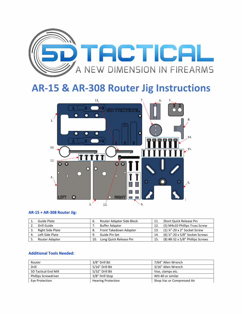
AR-15 & AR-308 Router Jig Instructions
AR-15 + AR-308 Router Jig:
1. Guide Plate 6. Router Adapter Side Block 11. Short Quick Release Pin
2. Drill Guide 7. Buffer Adapter 12. (5) M4x10 Phillips Truss Screw
3. Right Side Plate 8. Front Takedown Adapter 13. (1) ¼”-20 x 2” Socket Screw
4. Left Side Plate 9. Guide Pin Set 14. (6) ¼”-20 x 5/8” Socket Screws
5. Router Adapter 10. Long Quick Release Pin 15. (8) #8-32 x 5/8” Phillips Screws
Additional Tools Needed:
Router 3/8” Drill Bit 7/64” Allen Wrench
Drill 5/16” Drill Bit 3/16” Allen Wrench
5D Tactical End Mill 5/32” Drill Bit Vise, clamps etc.
Phillips Screwdriver 3/8” Drill Stop WD-40 or similar
Eye Protection Hearing Protection Shop Vac or Compressed Air
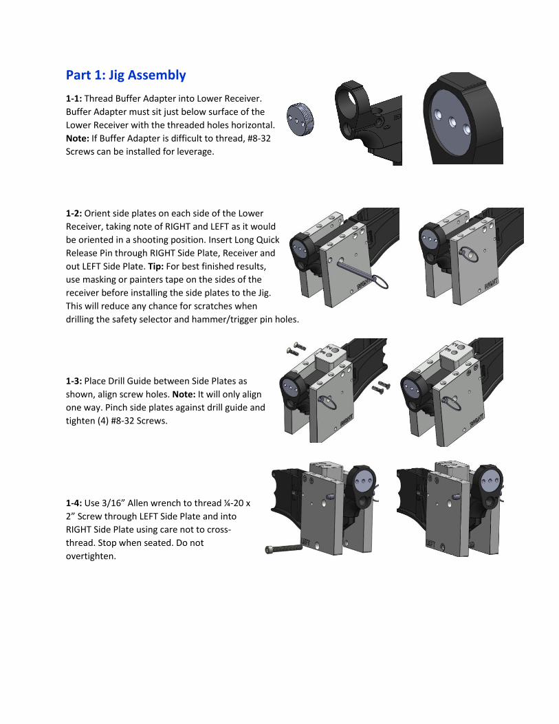
Part 1: Jig Assembly
1-1: Thread Buffer Adapter into Lower Receiver.
Buffer Adapter must sit just below surface of the
Lower Receiver with the threaded holes horizontal.
Note: If Buffer Adapter is difficult to thread, #8-32
Screws can be installed for leverage.
1-2: Orient side plates on each side of the Lower
Receiver, taking note of RIGHT and LEFT as it would
be oriented in a shooting position. Insert Long Quick
Release Pin through RIGHT Side Plate, Receiver and
out LEFT Side Plate. Tip: For best finished results,
use masking or painters tape on the sides of the
receiver before installing the side plates to the Jig.
This will reduce any chance for scratches when
drilling the safety selector and hammer/trigger pin holes.
1-3: Place Drill Guide between Side Plates as
shown, align screw holes. Note: It will only align
one way. Pinch side plates against drill guide and
tighten (4) #8-32 Screws.
1-4: Use 3/16” Allen wrench to thread ¼-20 x
2” Screw through LEFT Side Plate and into
RIGHT Side Plate using care not to cross-
thread. Stop when seated. Do not
overtighten.
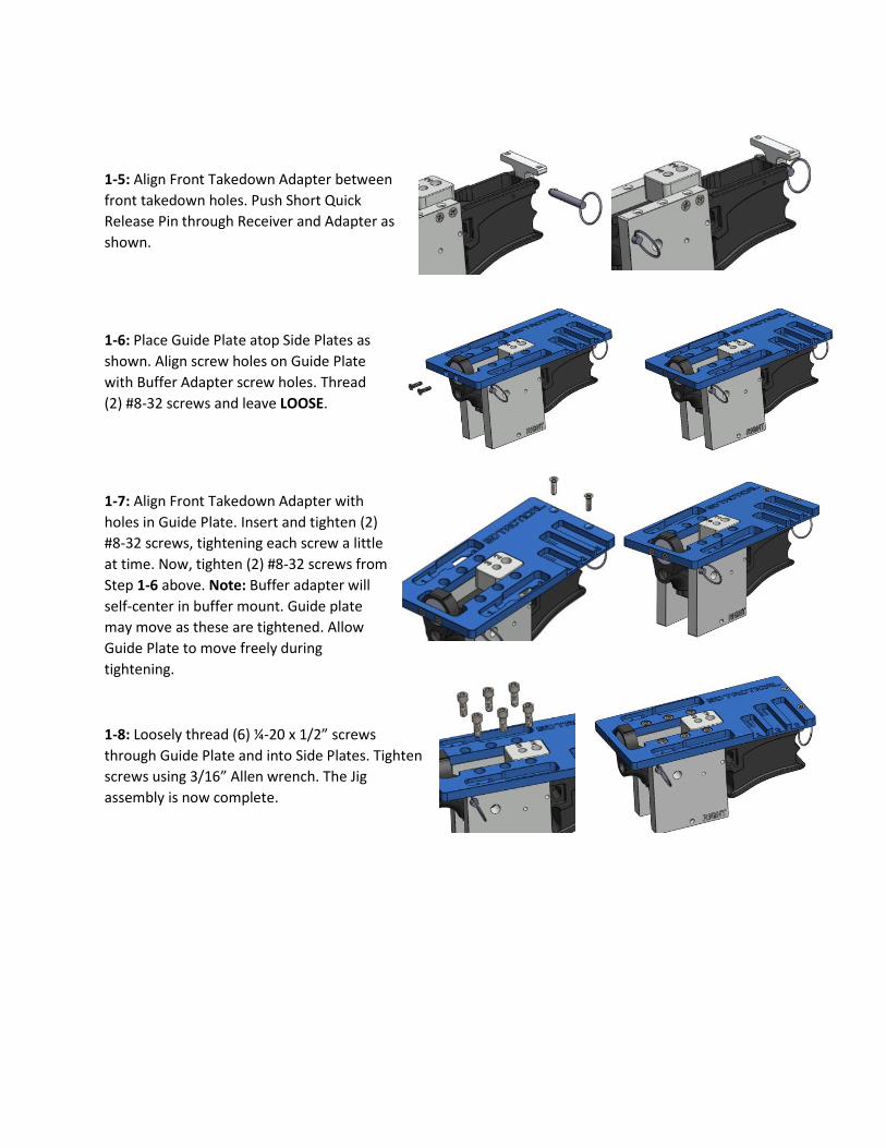
1-5: Align Front Takedown Adapter between
front takedown holes. Push Short Quick
Release Pin through Receiver and Adapter as
shown.
1-6: Place Guide Plate atop Side Plates as
shown. Align screw holes on Guide Plate
with Buffer Adapter screw holes. Thread
(2) #8-32 screws and leave LOOSE.
1-7: Align Front Takedown Adapter with
holes in Guide Plate. Insert and tighten (2)
#8-32 screws, tightening each screw a little
at time. Now, tighten (2) #8-32 screws from
Step 1-6 above. Note: Buffer adapter will
self-center in buffer mount. Guide plate
may move as these are tightened. Allow
Guide Plate to move freely during
tightening.
1-8: Loosely thread (6) ¼-20 x 1/2” screws
through Guide Plate and into Side Plates. Tighten
screws using 3/16” Allen wrench. The Jig
assembly is now complete.
Part 2: Drilling Step 1
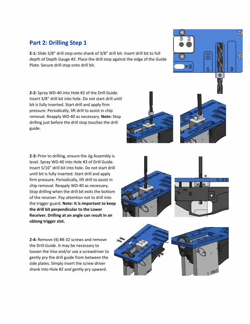
2-1: Slide 3/8” drill stop onto shank of 3/8” drill bit. Insert drill bit to full
depth of Depth Gauge #2. Place the drill stop against the edge of the Guide
Plate. Secure drill stop onto drill bit.
2-2: Spray WD-40 into Hole #2 of the Drill Guide.
Insert 3/8” drill bit into hole. Do not start drill until
bit is fully inserted. Start drill and apply firm
pressure. Periodically, lift drill to assist in chip
removal. Reapply WD-40 as necessary. Note: Stop
drilling just before the drill stop touches the drill
guide.
2-3: Prior to drilling, ensure the Jig Assembly is
level. Spray WD-40 into Hole #3 of Drill Guide.
Insert 5/16” drill bit into hole. Do not start drill
until bit is fully inserted. Start drill and apply
firm pressure. Periodically, lift drill to assist in
chip removal. Reapply WD-40 as necessary.
Stop drilling when the drill bit exits the bottom
of the receiver. Pay attention not to drill into
the trigger guard. Note: It is important to keep
the drill bit perpendicular to the Lower
Receiver. Drilling at an angle can result in an
oblong trigger slot.
2-4: Remove (4) #8-32 screws and remove
the Drill Guide. It may be necessary to
loosen the Vise and/or use a screwdriver to
gently pry the drill guide from between the
side plates. Simply insert the screw driver
shank into Hole #2 and gently pry upward.
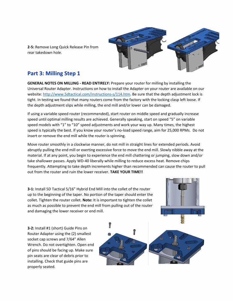
2-5: Remove Long Quick Release Pin from
rear takedown hole.
Part 3: Milling Step 1
GENERAL NOTES ON MILLING - READ ENTIRELY: Prepare your router for milling by installing the
Universal Router Adapter. Instructions on how to install the Adapter on your router are available on our
website: http://www.5dtactical.com/instructions-s/114.htm. Be sure that the depth adjustment lock is
tight. In testing we found that many routers come from the factory with the locking clasp left loose. If
the depth adjustment slips while milling, the end mill and/or lower can be damaged.
If using a variable speed router (recommended), start router on middle speed and gradually increase
speed until optimal milling results are achieved. Generally speaking, start on speed “5” on variable
speed models with “1” to “10” speed adjustments and work your way up. Many times, the highest
speed is typically the best. If you know your router’s no-load speed range, aim for 25,000 RPMs. Do not
insert or remove the end mill while the router is spinning.
Move router smoothly in a clockwise manner, do not mill in straight lines for extended periods. Avoid
abruptly pulling the end mill or exerting excessive force to move the end mill. Slowly nibble away at the
material. If at any point, you begin to experience the end mill chattering or jumping, slow down and/or
take shallower passes. Apply WD-40 liberally while milling to reduce excess heat. Remove chips
frequently. Attempting to take depth increments higher than recommended can cause the router to pull
out from the router and ruin the lower receiver. TAKE YOUR TIME!!
3-1: Install 5D Tactical 5/16” Hybrid End Mill into the collet of the router
up to the beginning of the taper. No portion of the taper should enter the
collet. Tighten the router collet. Note: It is important to tighten the collet
as much as possible to prevent the end mill from pulling out of the router
and damaging the lower receiver or end mill.
3-2: Install #1 (short) Guide Pins on
Router Adapter using the (2) smallest
socket cap screws and 7/64” Allen
Wrench. Do not overtighten. Open end
of pins should be facing up. Make sure
pin seats are clear of debris prior to
installing. Check that guide pins are
properly seated.
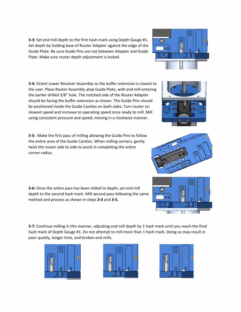
3-3: Set end mill depth to the first hash mark using Depth Gauge #1.
Set depth by holding base of Router Adapter against the edge of the
Guide Plate. Be sure Guide Pins are not between Adapter and Guide
Plate. Make sure router depth adjustment is locked.
3-4: Orient Lower Receiver Assembly so the buffer extension is closest to
the user. Place Router Assembly atop Guide Plate, with end mill entering
the earlier drilled 3/8” hole. The notched side of the Router Adapter
should be facing the buffer extension as shown. The Guide Pins should
be positioned inside the Guide Cavities on both sides. Turn router on
slowest speed and increase to operating speed once ready to mill. Mill
using consistent pressure and speed, moving in a clockwise manner.
3-5: Make the first pass of milling allowing the Guide Pins to follow
the entire area of the Guide Cavities. When milling corners, gently
twist the router side to side to assist in completing the entire
corner radius.
3-6: Once the entire pass has been milled to depth, set end mill
depth to the second hash mark. Mill second pass following the same
method and process as shown in steps 3-4 and 3-5.
3-7: Continue milling in this manner, adjusting end mill depth by 1 hash mark until you reach the final
hash mark of Depth Gauge #1. Do not attempt to mill more than 1 hash mark. Doing so may result in
poor quality, longer time, and broken end mills.
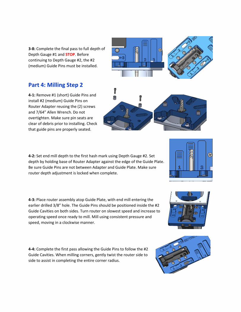
3-8: Complete the final pass to full depth of
Depth Gauge #1 and STOP. Before
continuing to Depth Gauge #2, the #2
(medium) Guide Pins must be installed.
Part 4: Milling Step 2
4-1: Remove #1 (short) Guide Pins and
install #2 (medium) Guide Pins on
Router Adapter reusing the (2) screws
and 7/64” Allen Wrench. Do not
overtighten. Make sure pin seats are
clear of debris prior to installing. Check
that guide pins are properly seated.
4-2: Set end mill depth to the first hash mark using Depth Gauge #2. Set
depth by holding base of Router Adapter against the edge of the Guide Plate.
Be sure Guide Pins are not between Adapter and Guide Plate. Make sure
router depth adjustment is locked when complete.
4-3: Place router assembly atop Guide Plate, with end mill entering the
earlier drilled 3/8” hole. The Guide Pins should be positioned inside the #2
Guide Cavities on both sides. Turn router on slowest speed and increase to
operating speed once ready to mill. Mill using consistent pressure and
speed, moving in a clockwise manner.
4-4: Complete the first pass allowing the Guide Pins to follow the #2
Guide Cavities. When milling corners, gently twist the router side to
side to assist in completing the entire corner radius.
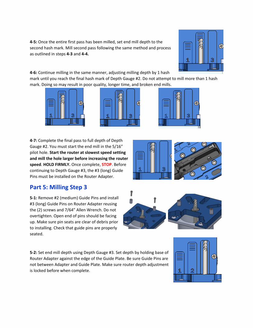
4-5: Once the entire first pass has been milled, set end mill depth to the
second hash mark. Mill second pass following the same method and process
as outlined in steps 4-3 and 4-4.
4-6: Continue milling in the same manner, adjusting milling depth by 1 hash
mark until you reach the final hash mark of Depth Gauge #2. Do not attempt to mill more than 1 hash
mark. Doing so may result in poor quality, longer time, and broken end mills.
4-7: Complete the final pass to full depth of Depth
Gauge #2. You must start the end mill in the 5/16”
pilot hole. Start the router at slowest speed setting
and mill the hole larger before increasing the router
speed. HOLD FIRMLY. Once complete, STOP. Before
continuing to Depth Gauge #3, the #3 (long) Guide
Pins must be installed on the Router Adapter.
Part 5: Milling Step 3
5-1: Remove #2 (medium) Guide Pins and install
#3 (long) Guide Pins on Router Adapter reusing
the (2) screws and 7/64” Allen Wrench. Do not
overtighten. Open end of pins should be facing
up. Make sure pin seats are clear of debris prior
to installing. Check that guide pins are properly
seated.
5-2: Set end mill depth using Depth Gauge #3. Set depth by holding base of
Router Adapter against the edge of the Guide Plate. Be sure Guide Pins are
not between Adapter and Guide Plate. Make sure router depth adjustment
is locked before when complete.
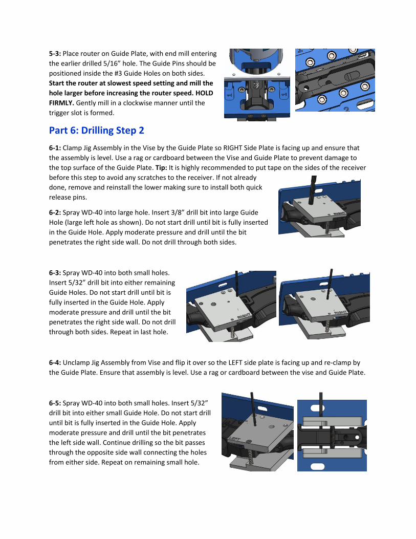
5-3: Place router on Guide Plate, with end mill entering
the earlier drilled 5/16” hole. The Guide Pins should be
positioned inside the #3 Guide Holes on both sides.
Start the router at slowest speed setting and mill the
hole larger before increasing the router speed. HOLD
FIRMLY. Gently mill in a clockwise manner until the
trigger slot is formed.
Part 6: Drilling Step 2
6-1: Clamp Jig Assembly in the Vise by the Guide Plate so RIGHT Side Plate is facing up and ensure that
the assembly is level. Use a rag or cardboard between the Vise and Guide Plate to prevent damage to
the top surface of the Guide Plate. Tip: It is highly recommended to put tape on the sides of the receiver
before this step to avoid any scratches to the receiver. If not already
done, remove and reinstall the lower making sure to install both quick
release pins.
6-2: Spray WD-40 into large hole. Insert 3/8” drill bit into large Guide
Hole (large left hole as shown). Do not start drill until bit is fully inserted
in the Guide Hole. Apply moderate pressure and drill until the bit
penetrates the right side wall. Do not drill through both sides.
6-3: Spray WD-40 into both small holes.
Insert 5/32” drill bit into either remaining
Guide Holes. Do not start drill until bit is
fully inserted in the Guide Hole. Apply
moderate pressure and drill until the bit
penetrates the right side wall. Do not drill
through both sides. Repeat in last hole.
6-4: Unclamp Jig Assembly from Vise and flip it over so the LEFT side plate is facing up and re-clamp by
the Guide Plate. Ensure that assembly is level. Use a rag or cardboard between the vise and Guide Plate.
6-5: Spray WD-40 into both small holes. Insert 5/32”
drill bit into either small Guide Hole. Do not start drill
until bit is fully inserted in the Guide Hole. Apply
moderate pressure and drill until the bit penetrates
the left side wall. Continue drilling so the bit passes
through the opposite side wall connecting the holes
from either side. Repeat on remaining small hole.
6-6: Spray WD-40 into large hole. Insert 3/8” drill bit
into large Guide Hole. Do not start drill until bit is fully
inserted in the Guide Hole. Apply moderate pressure
and drill until the bit penetrates the right side wall.
Continue drilling so the bit passes through the opposite
side wall connecting the holes from either side.
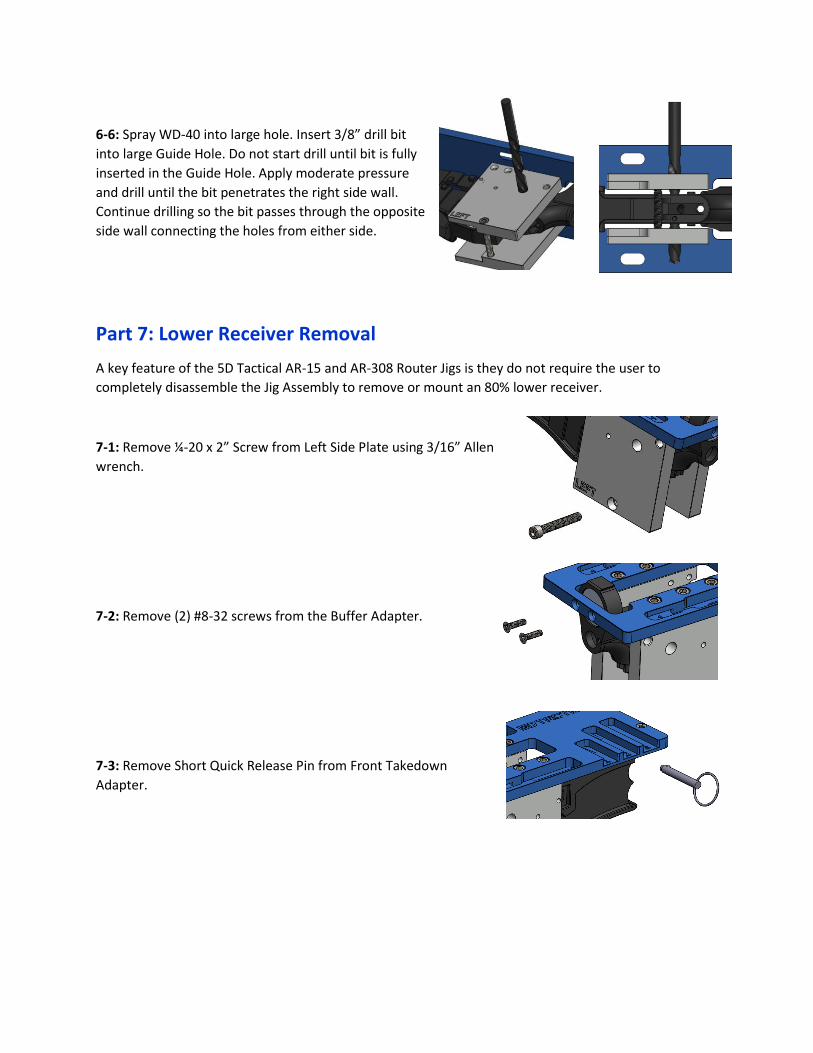
Part 7: Lower Receiver Removal
A key feature of the 5D Tactical AR-15 and AR-308 Router Jigs is they do not require the user to
completely disassemble the Jig Assembly to remove or mount an 80% lower receiver.
7-1: Remove ¼-20 x 2” Screw from Left Side Plate using 3/16” Allen
wrench.
7-2: Remove (2) #8-32 screws from the Buffer Adapter.
7-3: Remove Short Quick Release Pin from Front Takedown
Adapter.
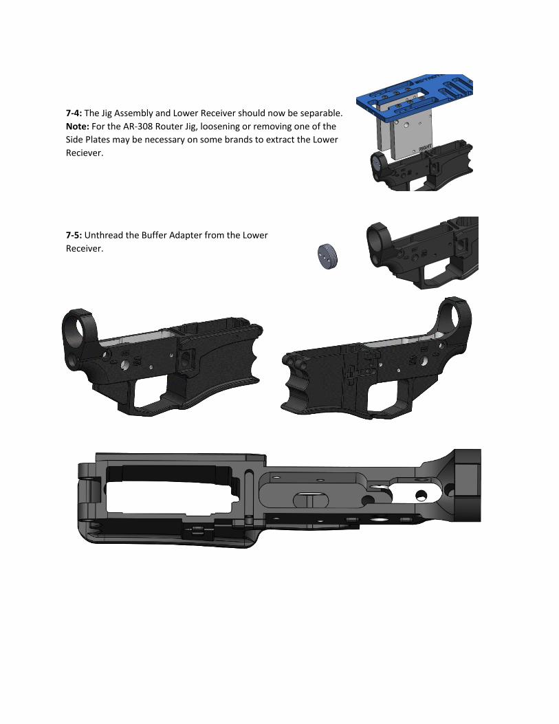
7-4: The Jig Assembly and Lower Receiver should now be separable.
Note: For the AR-308 Router Jig, loosening or removing one of the
Side Plates may be necessary on some brands to extract the Lower
Reciever.
7-5: Unthread the Buffer Adapter from the Lower
Receiver.