Embed Size (px)
Citation preview
Arbitrarily Layered Micro-Facet Surfaces
Andrea Weidlich and Alexander Wilkie
Abstract
In this paper we present a method to combine several micro-facetbased surface layers into a single unified, expressive BRDF modelthat is easy to use. The restriction to micro-facet based layers con-stitutes no loss of generality, since both perfectly specular and per-fectly diffuse surfaces can be seen as limit cases of the micro-facetapproach.
Such multi-layered surfaces can be used to re-create the appearanceof a wide range of different materials, and yield good results with-out having to perform explicit sub–surface scattering computations.
This is achieved through suitable approximations and simplifica-tions of the scattering within the simulated layered surface, whilestill taking absorption and total internal reflection into account. Wealso discuss the corresponding probability distribution function thatis needed for sampling purposes, and investigate how the flexibilityof this new approach is best put to use.
CR Categories: I.3.7 [Computer Graphics]: Three–DimensionalGraphics and Realism
Keywords: surface model, global illumination, microfacets
1 Introduction
During the last decades a number of analytical reflectance modelshave been developed for computer graphics use. These models canroughly be divided into two groups:
1. empirical – and usually physically implausible – models,which deliver reasonably good-looking results at moderatecomputational cost, and
2. those where comparatively expensive, physically based com-putations of light interacting with matter are used for highlyconvincing depictions of surfaces.
So far, complex layered surface models were not in general use inphotorealistic rendering, mainly because the derivation of a com-pound BRDF is rather difficult for a general arrangement of layers.However, under the – not unrealistic – assumption that the layersinvolved are thin compared to the size of the micro-facets, the prob-lem can be simplified in a way that still yields plausible results, butmaintains the flexibility of a full layered surface simulation.
The goal of this paper is to present a simple but still physically plau-sible BRDF model that can simulate both smooth and rough multi-layered surfaces, and which includes absorption within the layers,as well as total internal reflection. Our new model offers the user alarge flexibility in terms of what surfaces can be described with it,while still being intuitive to use, and – perhaps most importantly –also still physically plausible, despite the simplifications we applyto the problem.
The paper is structured as follows: we first give a short overview ofrelated work. In the main part of the paper we present our multi-layered surface model, and conclude by validating our results, andgiving an outlook to future research areas.
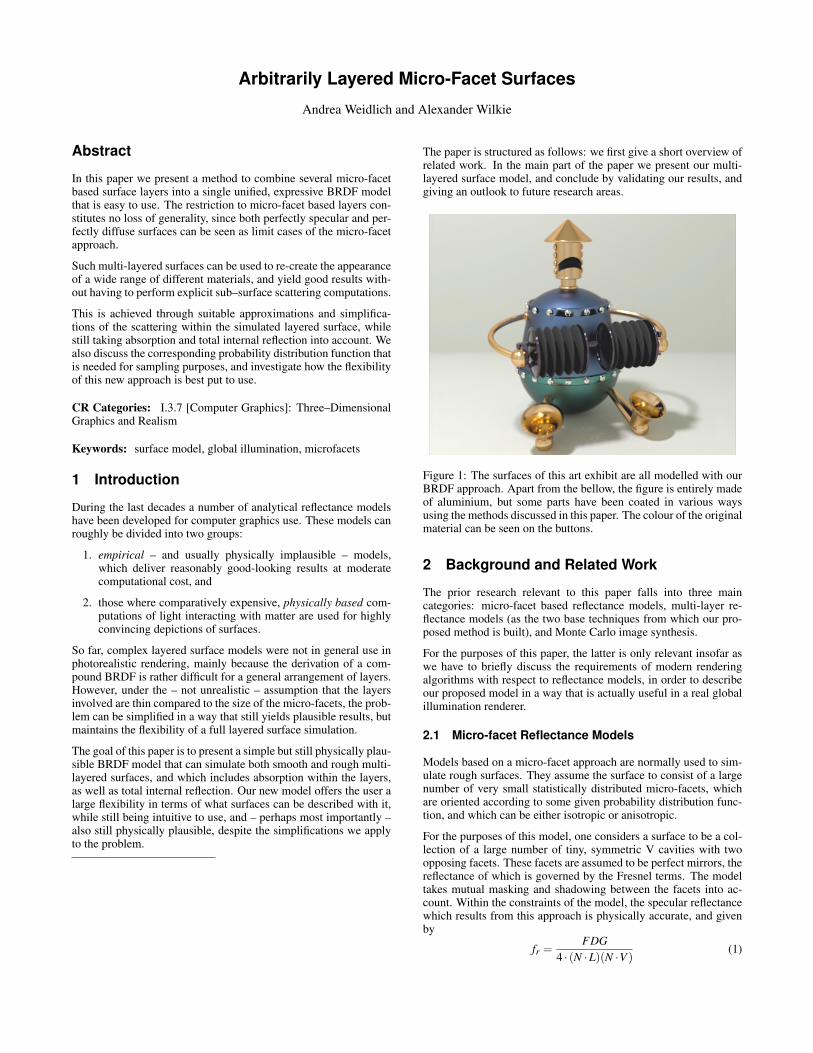
Figure 1: The surfaces of this art exhibit are all modelled with ourBRDF approach. Apart from the bellow, the figure is entirely madeof aluminium, but some parts have been coated in various waysusing the methods discussed in this paper. The colour of the originalmaterial can be seen on the buttons.
2 Background and Related Work
The prior research relevant to this paper falls into three maincategories: micro-facet based reflectance models, multi-layer re-flectance models (as the two base techniques from which our pro-posed method is built), and Monte Carlo image synthesis.
For the purposes of this paper, the latter is only relevant insofar aswe have to briefly discuss the requirements of modern renderingalgorithms with respect to reflectance models, in order to describeour proposed model in a way that is actually useful in a real globalillumination renderer.
2.1 Micro-facet Reflectance Models
Models based on a micro-facet approach are normally used to sim-ulate rough surfaces. They assume the surface to consist of a largenumber of very small statistically distributed micro-facets, whichare oriented according to some given probability distribution func-tion, and which can be either isotropic or anisotropic.
For the purposes of this model, one considers a surface to be a col-lection of a large number of tiny, symmetric V cavities with twoopposing facets. These facets are assumed to be perfect mirrors, thereflectance of which is governed by the Fresnel terms. The modeltakes mutual masking and shadowing between the facets into ac-count. Within the constraints of the model, the specular reflectancewhich results from this approach is physically accurate, and givenby
fr =FDG
4 · (N ·L)(N ·V )(1)
• D is the distribution function of the micro-facets.
• G is the geometric attenuation term that influences self-shadowing when the incident light is blocked, and self-masking when the reflected ray is blocked.
• F is the Fresnel term for each micro-facet which describes theamount of light that is refracted and reflected.
Micro-facet theory was brought to computer graphics proper in1982 by Cook and Torrance[Cook and Torrance 1982], who in-troduced a somewhat simplified and refined version of the origi-nal Torrance-Sparrow model that had been adapted to graphics use.Other micro-facet surface models are those of Oren and Nayar[Orenand Nayar 1994] (which is insofar unique, as it is up to now the onlytechnique to use Lambertian micro-facets), the Ward model[Ward1992] and the model of Ashikhmin [Ashikhmin and Shirley 2000].
2.2 Multi-Layer Reflectance Models
Layered surface models offer a great potential for creating veryconvincing renderings, and have already received a considerableamount of attention in computer graphics. The following list is byno means complete; due to space limitations we only give a briefoverview of those papers which are most relevant to our work.
Classical layered surface models are those of Kubelka andMunk [Kubelka and Munk 1931] and Hanrahan and Krueger [Han-rahan and Krueger 1993]. Both these models have no closed math-ematical form, and are therefore rarely used in practice – at leastfor image synthesis purposes. Based on the Kubelka–Munk model,Dorsey and Hanrahan [Dorsey and Hanrahan 1996] used layeredsurfaces to achieve surface aging effects. Icart and Arques [Icartand Arques 2000] [Icart and Arques 1999], as well as Hirayamaet al. [Hirayama et al. 2001a] [Hirayama et al. 2001b] [Hirayamaet al. 2000], presented approaches to accurately calculate the re-flectance properties - including interference effects - of multilayerfilms. Another model that describes interference and dispersion isthat of Granier and Heidrich [Granier and Heidrich 2003] .
Neumann and Neumann [Neumann and Neumann 1989] wereamongst the first to propose layered surface models. They discusstwo models, one that consists of a single perfectly smooth, transpar-ent layer over an arbitrary surface, and one with an arbitrary numberof layers. Both these models include absorption, but not internal re-flection. Since they do not give a sampling PDF for their compoundBRDFs, and neither a closed expression for the entire BRDF nor analgorithm to compute it, their work has to be considered somewhatincomplete.
Kelemen and Szirmay–Kalos [Kelemen and Szirmay-Kalos 2001]used the Cook-Torrance model in conjunction with layered sur-faces, albeit in a simplified form. Their model lacks the abilityto simulate absorption and internal reflections, and relies on a sim-plified variant of the Cook-Torrance model for its specular compo-nent. The diffuse component is described by a Lambertian term,and the combination of the two is dependent on the incident angle.They also provide an efficient scheme for sampling the BRDF in astochastic renderer.
Wilkie et al. [Wilkie et al. 2006] use a multi-layer reflectance modelwith a transparent, rough dielectric layer over a normal diffuse sur-face to describe the reflectance properties of diffuse fluorescent sur-faces, such as cardboard.
Another relevant surface model is that of Schlick [Schlick 1993].Although it is not an actual layered model, it should be mentionedhere since it can be used to mimic the appearance of layered sur-faces fairly well.
The appearance of multi-layered models was also indirectly simu-lated by Lafortune et al. [Lafortune et al. 1997]. A wide number ofdifferent surfaces can be reproduced by their technique, but it hastwo disadvantages: there is a high discrepancy to real surface be-haviour near grazing angles, and it is a purely empirical approach.
2.3 Monte Carlo Image Synthesis
While images of perfectly diffuse surfaces and perfect mirrors canbe rendered by a deterministic ray-tracer, surfaces with arbitrary re-flection properties are basically only tractable through Monte Carlorendering, e.g. bi-directional path tracing or photon tracing.
2.3.1 Sampling PDFs
Common to such expansion solvers of the rendering equation isthe fact that at each recursion level, they attempt to evaluate theillumination integral through stochastic numerical integration. Oneof the standard techniques to accelerate the convergence of sucha stochastic integration is to perform importance sampling, whichrequires that the integrand be randomly sampled using a probabilitydensity function that mimics the integrand as closely as possible.
In practice, this means that for any reflectance model one not onlyneeds formulas for its BRDF values, but also an efficient samplingPDF for the BRDF. While formulas for the BRDF are usually givenin literature, a sampling PDF is often omitted, which limits the im-mediate applicability of some published models.
2.3.2 Path Propagation vs. BRDF evaluation
It is rarely explicitly mentioned in rendering literature that one hasto be able to perform two distinct functions for each reflectancemodel one wishes to include in a stochastic renderer.
1. The first concerns the ability to correctly continue an incom-ing path according to a chosen sampling PDF. This is rathereasy to perform even for complicated multi-layer surfaces: foreach layer a suitable propagation direction can be recursivelycalculated, and is weighted according to its sampling proba-bility. One of these rays is then followed by random selection.
2. However, one also has to be able to evaluate the entire, com-bined BRDF for arbitrary input and output directions. Forarbitrary multi-layer surfaces the computation of this secondpiece of information is far from being trivial.
3 Arbitrarily Layered Micro-Facet Surfaces
As noted earlier, the idea of using individual surfaces of somewhatlimited applicability – such as perfect mirrors or Lambertian sur-faces – as layered components of a more sophisticated BRDF, isimmediately appealing due to its simplicity and usefulness.
While the concept of using layered surfaces is simple, actually us-ing it in a renderer is not – at least if the unrestricted case is con-sidered, because in this case the computation of the entire BRDF(item 2 from section 2.3.2), would – if done correctly – involvesub-surface scattering computations within the layers.
3.1 Simplification of the Problem
The key to using such surfaces without expensive sub-surface scat-tering computations is to perform four simplifications:
1. Any micro-facets are considered to be much larger in hori-zontal extent, than the layers are thick.
2. All rays that are generated by sampling of lower BRDF layers,are assumed to exit at the original point of incidence.
3. Refraction rays that are generated for the computation of theentire BRDF, are assumed to meet at a single point on the nextlayer interface.
4. All light scattering is due to reflection at the boundaries be-tween layers; no scattering occurs within individual layers.
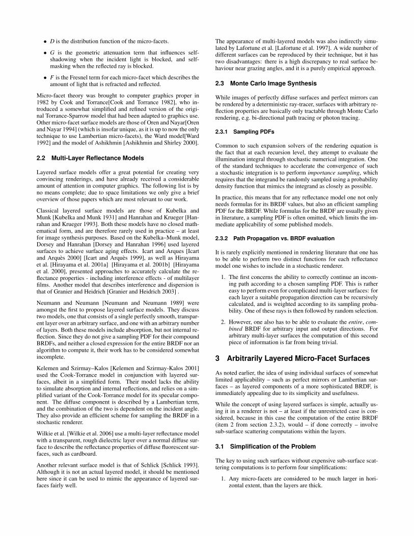
See figure 2 for a sketch of the simplified reflection and ray prop-agation geometry, and figure 4 for a BRDF evaluation sketch. Adetailed description of how exactly simplifications 2 and 3 turn outto be useful is given in section 3.2.
It is worth noting that none of these assumptions is entirely im-plausible: the first is consistent with the notion of only applyingvery thin layers atop a base substrate, while the second and thirdare reasonable simplifications under the circumstances – especiallywhen one considers that the micro-facets involved are assumed tobe statistically distributed entities in the first place.
In addition to these three simplifications, we impose one additionalrestriction: namely that the material used for any (partially) trans-parent layers only attenuates light passing through it, and does notcontribute any secondary scattering effects of its own. Since mostclear and tinted varnishes (which are one of the main targets for thismodel) do not exhibit noticeable scattering, this is not a particularlyhard restriction, though. We also assume any varnish layers to behomogeneous. The three simplifications, taken together with therestriction to non-scattering varnishes, are what allows us to omit afull sub-surface scattering computation.
It has to be noted, though, that due to the simplifications we per-form, our new approach does not constitute a general solution forsurface layers of arbitrary thickness and is limited to surfaces thathave layers thick enough to have the influence of absorption, andsufficiently thin enough that our simplifications hold true. How-ever, given the high quality of the results obtained by our method,we do not see this as an immediate concern, at least not for thoselayered surface types which are readily modelled by our approxi-mative approach.
!i !r
!i' !r'
Figure 2: Computation geometry and simplification of the sub-surface scattering in a layered surface during BRDF sampling. Anymicro-facet is large in relation to the layer thickness, which allowsus to do the following: (1) a ray will always leave through the samemicro-facet that it entered through, thereby eliminating the need toperform an intersection test with the nearby micro-facets. And (2),any exitant ray coming from a lower level will emanate from theoriginal point of entry (yellow dot), regardless of how oblique theexitant angle is. The direction of these rays is computed accordingto the correct geometry (dashed line).
3.2 Overview of the Model
Using our layered BRDF model poses two separate problems, thatcorrespond to the two tasks outlined in section 2.3.2:
1. We have to be able to cast samples according to the BRDF.
2. We have to be able to compute the entire BRDF for arbitraryinput and output directions.
The first problem can be solved by a recursive process that worksas follows:
1. Any light that hits an interface in the layer stack is partly re-flected, and partly refracted. The actual amount of energy thatwill be reflected is determined through Fresnel reflectance cal-culations – any surface in the stack (except for the very lastone, where this is optional) is assumed to be governed by theFresnel terms at least on a micro–facet level. An appropriatesampling direction is generated for the reflective component.
2. The refracted part of the energy is assumed to enter the ma-terial. A part of this will possibly be absorbed by the varnishmaterial, and the rest then interacts with the next, second sur-face in the stack - the process is recursively started at step 1for this interface.
3. All light that is reflected from lower layers is again attenuatedby the varnish on its upward path, and possibly subjected tototal internal reflection. This means that any directional sam-ples from lower layers have to be treated accordingly duringthe return from the recursion.
Figure 2 gives an overview of the geometrical simplification as-sociated with this process of generating directional samples. Thesecond problem – computation of the entire BRDF – also requiresa recursive approach:
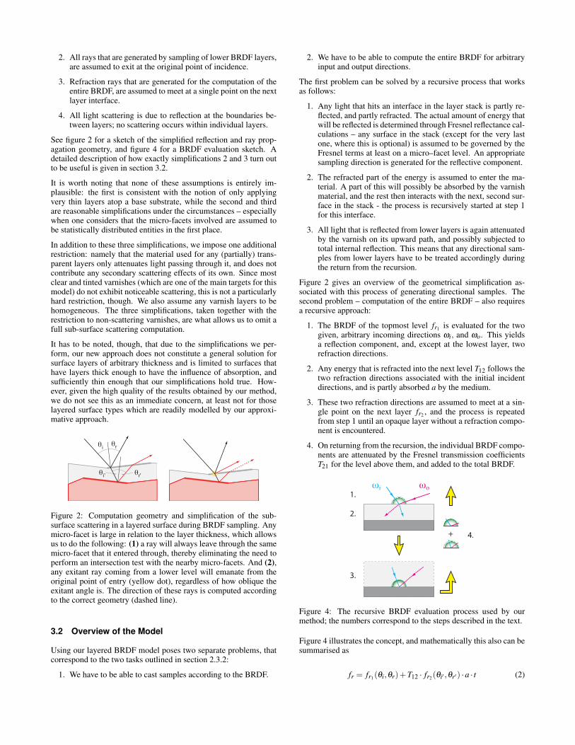
1. The BRDF of the topmost level fr1 is evaluated for the twogiven, arbitrary incoming directions ωi, and ωo. This yieldsa reflection component, and, except at the lowest layer, tworefraction directions.
2. Any energy that is refracted into the next level T12 follows thetwo refraction directions associated with the initial incidentdirections, and is partly absorbed a by the medium.
3. These two refraction directions are assumed to meet at a sin-gle point on the next layer fr2 , and the process is repeatedfrom step 1 until an opaque layer without a refraction compo-nent is encountered.
4. On returning from the recursion, the individual BRDF compo-nents are attenuated by the Fresnel transmission coefficientsT21 for the level above them, and added to the total BRDF.
1.
3.
4.+
2.
!i !o
Figure 4: The recursive BRDF evaluation process used by ourmethod; the numbers correspond to the steps described in the text.
Figure 4 illustrates the concept, and mathematically this also can besummarised as
fr = fr1(θi,θr)+T12 · fr2(θi′ ,θr′) ·a · t (2)
ΔH ΔC ΔL
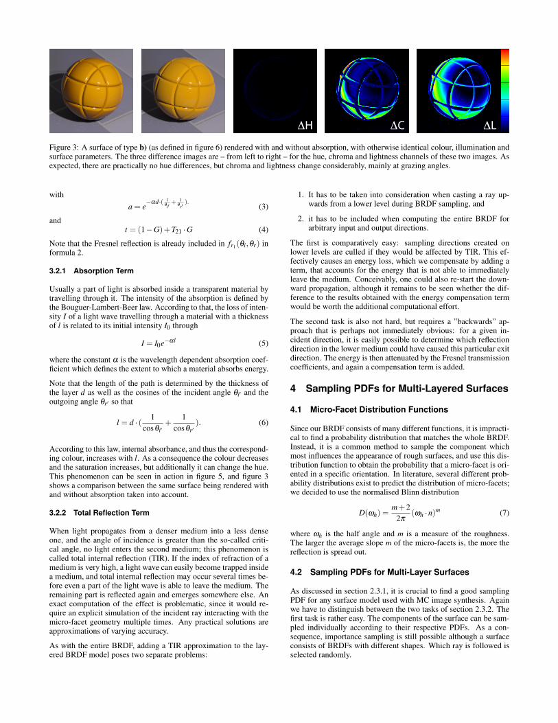
Figure 3: A surface of type b) (as defined in figure 6) rendered with and without absorption, with otherwise identical colour, illumination andsurface parameters. The three difference images are – from left to right – for the hue, chroma and lightness channels of these two images. Asexpected, there are practically no hue differences, but chroma and lightness change considerably, mainly at grazing angles.
witha = e
−αd·( 1θi′
+ 1θr′
).(3)
andt = (1−G)+T21 ·G (4)
Note that the Fresnel reflection is already included in fr1(θi,θr) informula 2.
3.2.1 Absorption Term
Usually a part of light is absorbed inside a transparent material bytravelling through it. The intensity of the absorption is defined bythe Bouguer-Lambert-Beer law. According to that, the loss of inten-sity I of a light wave travelling through a material with a thicknessof l is related to its initial intensity I0 through
I = I0e−αl (5)
where the constant α is the wavelength dependent absorption coef-ficient which defines the extent to which a material absorbs energy.
Note that the length of the path is determined by the thickness ofthe layer d as well as the cosines of the incident angle θi′ and theoutgoing angle θr′ so that
l = d · ( 1cosθi′
+1
cosθr′). (6)
According to this law, internal absorbance, and thus the correspond-ing colour, increases with l. As a consequence the colour decreasesand the saturation increases, but additionally it can change the hue.This phenomenon can be seen in action in figure 5, and figure 3shows a comparison between the same surface being rendered withand without absorption taken into account.
3.2.2 Total Reflection Term
When light propagates from a denser medium into a less denseone, and the angle of incidence is greater than the so-called criti-cal angle, no light enters the second medium; this phenomenon iscalled total internal reflection (TIR). If the index of refraction of amedium is very high, a light wave can easily become trapped insidea medium, and total internal reflection may occur several times be-fore even a part of the light wave is able to leave the medium. Theremaining part is reflected again and emerges somewhere else. Anexact computation of the effect is problematic, since it would re-quire an explicit simulation of the incident ray interacting with themicro-facet geometry multiple times. Any practical solutions areapproximations of varying accuracy.
As with the entire BRDF, adding a TIR approximation to the lay-ered BRDF model poses two separate problems:
1. It has to be taken into consideration when casting a ray up-wards from a lower level during BRDF sampling, and
2. it has to be included when computing the entire BRDF forarbitrary input and output directions.
The first is comparatively easy: sampling directions created onlower levels are culled if they would be affected by TIR. This ef-fectively causes an energy loss, which we compensate by adding aterm, that accounts for the energy that is not able to immediatelyleave the medium. Conceivably, one could also re-start the down-ward propagation, although it remains to be seen whether the dif-ference to the results obtained with the energy compensation termwould be worth the additional computational effort.
The second task is also not hard, but requires a ”backwards” ap-proach that is perhaps not immediately obvious: for a given in-cident direction, it is easily possible to determine which reflectiondirection in the lower medium could have caused this particular exitdirection. The energy is then attenuated by the Fresnel transmissioncoefficients, and again a compensation term is added.
4 Sampling PDFs for Multi-Layered Surfaces
4.1 Micro-Facet Distribution Functions
Since our BRDF consists of many different functions, it is impracti-cal to find a probability distribution that matches the whole BRDF.Instead, it is a common method to sample the component whichmost influences the appearance of rough surfaces, and use this dis-tribution function to obtain the probability that a micro-facet is ori-ented in a specific orientation. In literature, several different prob-ability distributions exist to predict the distribution of micro-facets;we decided to use the normalised Blinn distribution
D(ωh) =m+2
2π(ωh ·n)m (7)
where ωh is the half angle and m is a measure of the roughness.The larger the average slope m of the micro-facets is, the more thereflection is spread out.
4.2 Sampling PDFs for Multi-Layer Surfaces
As discussed in section 2.3.1, it is crucial to find a good samplingPDF for any surface model used with MC image synthesis. Againwe have to distinguish between the two tasks of section 2.3.2. Thefirst task is rather easy. The components of the surface can be sam-pled individually according to their respective PDFs. As a con-sequence, importance sampling is still possible although a surfaceconsists of BRDFs with different shapes. Which ray is followed isselected randomly.
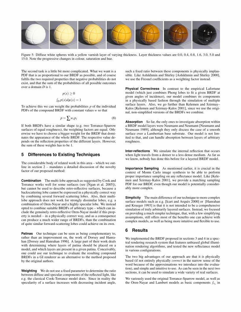
Figure 5: Diffuse white spheres with a yellow varnish layer of varying thickness. Layer thickness values are 0.0, 0.4, 0.8, 1.6, 3.0, 5.0 and15.0. Note the progressive changes in colour, saturation and hue.
The second task is a little bit more complicated. What we want is aPDF that is as proportional to our BRDF as possible, and of coursefulfils the two required properties that negative probabilities do notexist, and that the sum of the probabilities of all possible outcomesover a domain D is 1.
p(x) ≥ 0∫D p(x)dµ(x) = 1
To achieve this we can weight the probabilities p of the individualPDFs of the compound BRDF with constant values w so that
p = ∑wi pi (8)
If both BRDFs have a similar shape (e.g. two Torrance-Sparrowsurfaces of equal roughness), the weighting factors are equal. Oth-erwise we have to choose a bigger weight for the BRDF that domi-nates the appearance of the whole BRDF. The respective value de-pends on the reflection properties of the different layers. However,the sum of these weights has to be 1.
5 Differences to Existing Techniques
The considerable body of related work in this area – which we out-line in section 2 – mandates a detailed discussion of the noveltyfactor of our proposed method:
Combination The multi-lobe approach as suggested by Cook andTorrance works well for some surfaces (see [Ngan et al. 2005]),but cannot be used to describe retro-reflective surfaces, because abackscattering lobe cannot be expressed in a physically correct wayby combining several forward scattering lobes. Also, their multi-lobe approach does not work for strongly dissimilar lobes, e.g. acombination of Oren-Nayar and a highly specular lobe. We insteadopted to combine suitable BRDFs of arbitrary type – which can in-clude the genuinely retro-reflective Oren-Nayar model if this prop-erty is needed – in a physically correct way, and as a consequencecan produce a much wider range of BRDFs, than the combinationof quite similar forward-scattering lobes could achieve on its own.
Patinas Our technique can be seen as being complementary to,rather than an improvement on, the work of Dorsey and Hanra-han [Dorsey and Hanrahan 1996]. A large part of their work dealswith determining where layers of patina should be placed on amodel, and which layers are present in a given patina. Conceivably,one could use our technique to evaluate the resulting compoundBRDFs in a GI renderer as an alternative to the method proposedby the original authors.
Weighting We do not use a fixed parameter to determine the ratiobetween diffuse and specular components of the reflected light, likee.g. the classical Cook-Torrance model does. Since in reality thespecularity of a surface increases with decreasing incident angle,
such a fixed ratio between these components is physically implau-sible. Like Ashikhmin and Shirley [Ashikhmin and Shirley 2000],we use the Fresnel coefficients as a weighting factor instead.
Physical Correctness In contrast to the empirical Lafortunemodel (which just combines Phong lobes to fit a given BRDF atgiven angles of incidence), our model combines its componentsin a physically based fashion through the simulation of multiplesurface layers. Also, we go further than Kelemen and Szirmay–Kalos [Kelemen and Szirmay-Kalos 2001], since we use the origi-nal, non-simplified versions of the BRDFs we combine.
Absorption So far, the only ones to investigate absorption withina BRDF model layers were Neumann and Neumann [Neumann andNeumann 1989], although they only discuss the case of a smoothsurface over a Lambertian base substrate. Our model is not lim-ited to that, and can handle absorption between layers of arbitraryroughness.
Inter-reflections We simulate the internal reflection that occurswhen light travels from a denser to a less dense medium. As far aswe know, nobody has done this before for a layered BRDF model.
Importance Sampling As mentioned earlier, it is crucial in thecontext of Monte Carlo image synthesis to be able to performproper importance sampling on any reflectance model. Like [Kele-men and Szirmay-Kalos 2001], we provide a matching samplingPDF for our BRDF, even though our model is potentially consider-ably more complex.
Simplicity The main difference of our technique to more complexsurface models such as e.g. [Icart and Arques 2000] or [Hanrahanand Krueger 1993] is that it is not intended to be a comprehensivesimulation of truly arbitrarily layered surfaces. Instead, we focusedon providing a much simpler technique, that, with a few simplifyingassumptions, still offers most of the benefits one can achieve withcomplex models, as well as being more intuitive and flexible to use.
6 Results
We implemented the BRDF proposed in sections 3 and 4 in a spec-tral rendering research system that features unbiased global illumi-nation rendering algorithms, and tested the new reflectance modelin various configurations.
The two big advantages of our approach are that it is physicallybased (if not entirely physically correct in the narrow sense of theword because of the approximations we introduce into the evalua-tion), and simple and intuitive to use. As can be seen in the next twosections, it can be used to simulate a wide variety of real surfaces.
We variously used the original Torrance-Sparrow model, as well asthe Oren-Nayar and Lambert models as basic components frn in
a)Glossy Paint
c)Frosted Paint
d)Metal Foil
e)Metallic Paint
f)Frosted Metal
g)Patina
b)Tinted Glazing
h)Multi-Layer
Torrance-Sparrow
Diffuse
Smooth
Metal
Coloured Solid
Interfaces: Materials:
Colourless Solid
Tinted Varnish
Clear Varnish
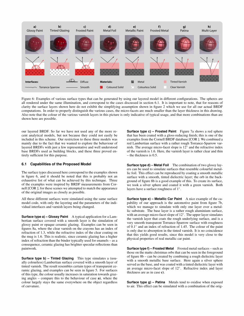
Figure 6: Examples of various surface types that can be generated by using our layered model in different configurations. The spheres areall rendered under the same illumination, and correspond to the cases discussed in section 6.1. It is important to note, that for reasons ofclarity the surface layers shown here do not exhibit the simplifying assumption shown in figure 2 which we use for all our actual BRDFcomputations. In order to properly distinguish the various cases, the micro-facets are much smaller than the layer thickness in this drawing.Also note that the colour of the various varnish layers in this picture is only indicative of typical usage, and that more combinations than areshown here are possible.
our layered BRDF. So far we have not used any of the more re-cent analytical models, but not because they could not easily beincluded in this scheme. Our restriction to these three models wasmainly due to the fact that we wanted to explore the behaviour oflayered BRDFs with just a few representative and well understoodbase BRDFs used as building blocks, and these three proved en-tirely sufficient for this purpose.
6.1 Capabilities of the Proposed Model
The surface types discussed here correspond to the examples shownin figure 6, and it should be noted that this is probably not anexhaustive list of what can be achieved by this technique. Threeof the examples were inspired by BRDF measurements from Cor-nell [COR ]; for these scenes we attempted to match the appearanceof the original images as closely as possible.
All these different surfaces were simulated using the same surfacemodel code, with only the layering and the parameters of the indi-vidual interfaces and varnish layers being changed.
Surface type a) – Glossy Paint A typical application for a Lam-bertian surface covered with a smooth layer is the simulation ofglossy paint or opaque ceramic glazing. Examples can be seen infigures 8a, where the clear varnish on the crayons has an index ofrefraction of 1.3, while the refractive index of the clear coating onthe mug is 1.6. This is realistic, since ceramic glazing has a higherindex of refraction than the binder typically used for enamels – as aconsequence, ceramic glazing has brighter specular reflections thanpaintwork.
Surface type b) – Tinted Glazing This type simulates a (usu-ally colourless) Lambertian surface covered with a smooth layer oftinted varnish. The result resembles certain types of transparent ce-ramic glazing, and examples can be seen in figure 5. For surfacesof this type, the colour usually increases in saturation towards graz-ing angles – compare this to the behaviour of case a), where thecolour largely stays the same everywhere on the object regardlessof curvature.
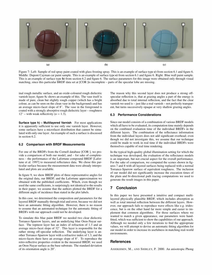
Surface type c) – Frosted Paint Figure 7a shows a red spherethat has been coated with a gloss-reducing finish; this is one of theexamples from the Cornell BRDF database [COR ]. We combined ared Lambertian surface with a rather rough Torrance-Sparrow var-nish. The average micro-facet slope is 12◦ and the refractive indexof the varnish is 1.6. Here, the varnish layer is rather clear and thin– the thickness is 0.5.
Surface type d) – Metal Foil The combination of two glossy lay-ers can be used to simulate surfaces that resemble colourful metal-lic foil. This effect can be reproduced by coating a smooth metallicsurface with a smooth, tinted dielectric layer; the orb in the back-ground of figure 8b is a good example of this. To create its surface,we took a silver sphere and coated it with a green varnish. Bothlayers have a surface roughness of 1◦.
Surface type e) – Metallic Car Paint A nice example of the ca-pability of our approach is the automotive paint from figure 7b,which we manage to simulate with only one layer over a metal-lic substrate. The base layer is a rather rough aluminium surface,with an average micro-facet slope of 12◦. The upper layer simulatesthe varnish layer that coats the rough underlying surface, and is avery smooth transparent Torrance-Sparrow surface with roughnessof 0.1◦ and an index of refraction of 1.45. The colour of the paintis only due to absorption in the tinted varnish. It is no coincidencethat this yields good results, since this model is very close to thephysical properties of real metallic car paint.
Surface type f) – Frosted Metal Frosted metal surfaces – such asthose on the matte christmas orbs that can be seen in the foregroundof figure 8b – can be created by combining a rough dielectric layerwith a smooth metallic base surface. Here again a silver sphereserved as the base, and was coated with a tinted dielectric layer withan average micro-facet slope of 12◦. Refractive index and layerthickness are as in case c).
Surface type g) – Patina Metals tend to oxidise when exposedto air. This effect can be simulated with a combination of the orig-
(a) (b) (c)
Figure 7: Left: Sample of red spray paint coated with glass frosting spray. This is an example of surface type c) from section 6.1 and figure 6.Middle: Dupont Cayman car paint sample. This is an example of surface type e) from section 6.1 and figure 6. Right: Blue wall paint sample.This is an example of surface type h) from section 6.2 and figure 6. The surface parameters for this image were obtained only through visualmatching, since this particular BRDF data set at [COR ]is incomplete – parts of the specular lobe are missing.
inal rough metallic surface, and an oxide-coloured rough dielectricvarnish layer; figure 8c shows an example of this. The vase itself ismade of pure, clean but slightly rough copper (which has a brightcolour, as can be seen on the clean vase in the background) and hasan average micro-facet slope of 8◦. The vase in the foreground iscoated with a strongly absorptive rough dielectric layer – roughness12◦ – with weak reflectivity (n = 1.3).
Surface type h) – Multilayered Varnish For most applicationsit is apparently sufficient to use only one varnish layer. However,some surfaces have a microfacet distribution that cannot be simu-lated with only one layer. An example of such a surface is discussedin section 6.2.
6.2 Comparison with BRDF Measurements
For one of the BRDFs from the Cornell database [COR ], we pro-vide a comparison of both our model, and – for sake of complete-ness – the performance of the Lafortune compound BRDF [Lafor-tune et al. 1997] to measured reflectance data. We chose this par-ticular surface because the measurement data were already interpo-lated and plots are available.
In figure 9, we show BRDF plots of three representative angles forthe original data, our BRDF, and the Lafortune approximation weobtained with the published coefficients. Which, even though weused the same coefficients, is surprisingly not identical to the resultsin their paper; we assume that the authors plotted the BRDF for adifferent angle of incidence than stated in the plot labels.
In this case, we determined the composition and parameters for thelayered BRDF manually through trial and error, because we did nothave an automatic fitting algorithm. However, there is no reasonto assume that an automated technique for the automatic fitting ofBRDFs with our approach could not be developed.
To simulate this blue paint BRDF we needed two clear dielectricTorrance-Sparrow layers, and an underlying blue Oren-Nayar sur-face. The topmost layer has an index of refraction of 1.3 and anaverage micro-facet slope of 32◦. This layer is responsible for therather strong off-specular reflection. The underlying layer is an-other Torrance-Sparrow layer with a refractive index of 1.3, and themicro-facets there have an average slope of 8◦. To reproduce theretro-reflective properties evident in the measured BRDF, we usedan Oren-Nayar surface as the base substrate. The standard deviationof its orientation angle is 20◦.
The reason why this second layer does not produce a strong off-specular reflection is, that at grazing angles a part of the energy isabsorbed due to total internal reflection, and the fact that the clearvarnish we used is – just like a real varnish – not perfectly transpar-ent, but turns successively opaque at very shallow grazing angles.
6.3 Performance Considerations
Since our model consists of a combination of various BRDF modelswhich all have to be evaluated, its computation time mainly dependson the combined evaluation time of the individual BRDFs in thedifferent layers. The combination of the reflectance informationfrom the individual layers does not add significant overhead; eventhough we did not investigate this, we assume that our techniquecould be made to work in real time if the individual BRDFs werethemselves capable of real time rendering.
In the typical high-quality global illumination setting for which thetechnique was developed, the evaluation of the reflectance modelsis an important, but not crucial aspect for the overall performance.For the sake of comparison, we computed the scenes shown in fig-ures 7 and 8 with all layered surfaces being replaced with a normalTorrance-Sparrow surface of equivalent roughness. The inclusionof our model did not significantly increase the execution times ofthe plain and bi-directional path tracing computations we used togenerate the result images in this paper.
7 Conclusion
In this paper we have presented a intuitive and compact multi-layered physically plausible BRDF, which includes absorption aswell as total internal reflection between the different layers. How-ever, our approach fails to reproduce wave effects like e.g. irides-cence, but is on the other hand far more simple and easier to im-plement that common algorithms. For those surfaces where wewanted to match a given appearance, our parameters were hand-fitted, which was sufficient to show the capabilities of our approach.Although we needed only a few iterations to find the appropriatevalues, we will attempt to devise an automatic fitting algorithm forour model in order to increase its usefulness in matching real-worldenvironments.
References
ASHIKHMIN, M., AND SHIRLEY, P. 2000. An anisotropic Phong
(a) (b) (c)
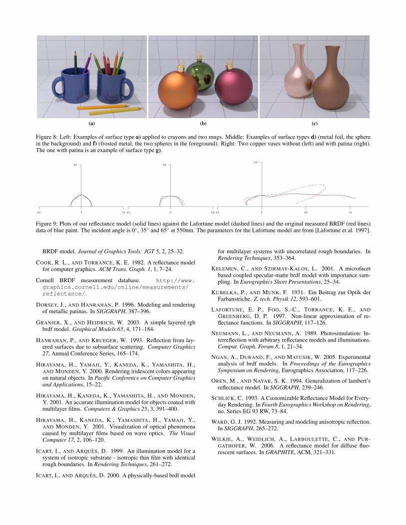
Figure 8: Left: Examples of surface type a) applied to crayons and two mugs. Middle: Examples of surface types d) (metal foil, the spherein the background) and f) (frosted metal, the two spheres in the foreground). Right: Two copper vases without (left) and with patina (right).The one with patina is an example of surface type g).
0 0.50.5
0.5
0 0.50.5
0.5
0 0.5 1.00.5
0.5
Figure 9: Plots of our reflectance model (solid lines) against the Lafortune model (dashed lines) and the original measured BRDF (red lines)data of blue paint. The incident angle is 0◦, 35◦ and 65◦ at 550nm. The parameters for the Lafortune model are from [Lafortune et al. 1997].
BRDF model. Journal of Graphics Tools: JGT 5, 2, 25–32.
COOK, R. L., AND TORRANCE, K. E. 1982. A reflectance modelfor computer graphics. ACM Trans. Graph. 1, 1, 7–24.
Cornell BRDF measurement database. http://www.graphics.cornell.edu/online/measurements/reflectance/.
DORSEY, J., AND HANRAHAN, P. 1996. Modeling and renderingof metallic patinas. In SIGGRAPH, 387–396.
GRANIER, X., AND HEIDRICH, W. 2003. A simple layered rgbbrdf model. Graphical Models 65, 4, 171–184.
HANRAHAN, P., AND KRUEGER, W. 1993. Reflection from lay-ered surfaces due to subsurface scattering. Computer Graphics27, Annual Conference Series, 165–174.
HIRAYAMA, H., YAMAJI, Y., KANEDA, K., YAMASHITA, H.,AND MONDEN, Y. 2000. Rendering iridescent colors appearingon natural objects. In Pacific Conference on Computer Graphicsand Applications, 15–22.
HIRAYAMA, H., KANEDA, K., YAMASHITA, H., AND MONDEN,Y. 2001. An accurate illumination model for objects coated withmultilayer films. Computers & Graphics 25, 3, 391–400.
HIRAYAMA, H., KANEDA, K., YAMASHITA, H., YAMAJI, Y.,AND MONDEN, Y. 2001. Visualization of optical phenomenacaused by multilayer films based on wave optics. The VisualComputer 17, 2, 106–120.
ICART, I., AND ARQUES, D. 1999. An illumination model for asystem of isotropic substrate - isotropic thin film with identicalrough boundaries. In Rendering Techniques, 261–272.
ICART, I., AND ARQUES, D. 2000. A physically-based brdf model
for multilayer systems with uncorrelated rough boundaries. InRendering Techniques, 353–364.
KELEMEN, C., AND SZIRMAY-KALOS, L. 2001. A microfacetbased coupled specular-matte brdf model with importance sam-pling. In Eurographics Short Presentations, 25–34.
KUBELKA, P., AND MUNK, F. 1931. Ein Beitrag zur Optik derFarbanstriche. Z. tech. Physik 12, 593–601.
LAFORTUNE, E. P., FOO, S.-C., TORRANCE, K. E., ANDGREENBERG, D. P. 1997. Non-linear approximation of re-flectance functions. In SIGGRAPH, 117–126.
NEUMANN, L., AND NEUMANN, A. 1989. Photosimulation: In-terreflection with arbitrary reflectance models and illuminations.Comput. Graph. Forum 8, 1, 21–34.
NGAN, A., DURAND, F., AND MATUSIK, W. 2005. Experimentalanalysis of brdf models. In Proceedings of the EurographicsSymposium on Rendering, Eurographics Association, 117–226.
OREN, M., AND NAYAR, S. K. 1994. Generalization of lambert’sreflectance model. In SIGGRAPH, 239–246.
SCHLICK, C. 1993. A Customizable Reflectance Model for Every-day Rendering. In Fourth Eurographics Workshop on Rendering,no. Series EG 93 RW, 73–84.
WARD, G. J. 1992. Measuring and modeling anisotropic reflection.In SIGGRAPH, 265–272.
WILKIE, A., WEIDLICH, A., LARBOULETTE, C., AND PUR-GATHOFER, W. 2006. A reflectance model for diffuse fluo-rescent surfaces. In GRAPHITE, ACM, 321–331.