Embed Size (px)
Citation preview
Arbitrary Waveform GeneratorsAWG5000 Series Data Sheet
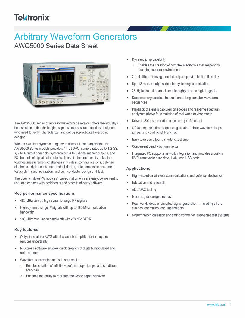
The AWG5000 Series of arbitrary waveform generators offers the industry'sbest solution to the challenging signal stimulus issues faced by designerswho need to verify, characterize, and debug sophisticated electronicdesigns.
With an excellent dynamic range over all modulation bandwidths, theAWG5000 Series models provide a 14-bit DAC, sample rates up to 1.2 GS/s, 2 to 4 output channels, synchronized 4 to 8 digital marker outputs, and28 channels of digital data outputs. These instruments easily solve thetoughest measurement challenges in wireless communications, defenseelectronics, digital consumer product design, data conversion equipment,test system synchronization, and semiconductor design and test.
The open windows (Windows 7) based instruments are easy, convenient touse, and connect with peripherals and other third-party software.
Key performance specifications
480 MHz carrier, high dynamic range RF signals
High dynamic range IF signals with up to 180 MHz modulationbandwidth
180 MHz modulation bandwidth with -58 dBc SFDR
Key features
Only stand-alone AWG with 4 channels simplifies test setup andreduces uncertainty
RFXpress software enables quick creation of digitally modulated andradar signals
Waveform sequencing and sub-sequencingEnables creation of infinite waveform loops, jumps, and conditionalbranchesEnhance the ability to replicate real-world signal behavior
Dynamic jump capabilityEnables the creation of complex waveforms that respond tochanging external environment
2 or 4 differential/single-ended outputs provide testing flexibility
Up to 8 marker outputs ideal for system synchronization
28 digital output channels create highly precise digital signals
Deep memory enables the creation of long complex waveformsequences
Playback of signals captured on scopes and real-time spectrumanalyzers allows for simulation of real-world environments
Down to 800 ps resolution edge timing shift control
8,000 steps real-time sequencing creates infinite waveform loops,jumps, and conditional branches
Easy to use and learn, shortens test time
Convenient bench-top form factor
Integrated PC supports network integration and provides a built-inDVD, removable hard drive, LAN, and USB ports
Applications
High-resolution wireless communications and defense electronics
Education and research
ADC/DAC testing
Mixed-signal design and test
Real-world, ideal, or distorted signal generation – including all theglitches, anomalies, and Impairments
System synchronization and timing control for large-scale test systems
www.tek.com 1
Industry's best mixed signal stimulussolution for today's complex measurementchallenges
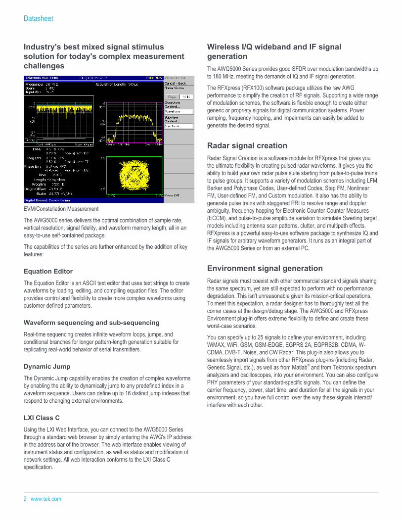
EVM/Constellation Measurement
The AWG5000 series delivers the optimal combination of sample rate,vertical resolution, signal fidelity, and waveform memory length, all in aneasy-to-use self-contained package.
The capabilities of the series are further enhanced by the addition of keyfeatures:
Equation Editor
The Equation Editor is an ASCII text editor that uses text strings to createwaveforms by loading, editing, and compiling equation files. The editorprovides control and flexibility to create more complex waveforms usingcustomer-defined parameters.
Waveform sequencing and sub-sequencing
Real-time sequencing creates infinite waveform loops, jumps, andconditional branches for longer pattern-length generation suitable forreplicating real-world behavior of serial transmitters.
Dynamic Jump
The Dynamic Jump capability enables the creation of complex waveformsby enabling the ability to dynamically jump to any predefined index in awaveform sequence. Users can define up to 16 distinct jump indexes thatrespond to changing external environments.
LXI Class C
Using the LXI Web Interface, you can connect to the AWG5000 Seriesthrough a standard web browser by simply entering the AWG's IP addressin the address bar of the browser. The web interface enables viewing ofinstrument status and configuration, as well as status and modification ofnetwork settings. All web interaction conforms to the LXI Class Cspecification.
Wireless I/Q wideband and IF signalgenerationThe AWG5000 Series provides good SFDR over modulation bandwidths upto 180 MHz, meeting the demands of IQ and IF signal generation.
The RFXpress (RFX100) software package utilizes the raw AWGperformance to simplify the creation of RF signals. Supporting a wide rangeof modulation schemes, the software is flexible enough to create eithergeneric or propriety signals for digital communication systems. Powerramping, frequency hopping, and impairments can easily be added togenerate the desired signal.
Radar signal creationRadar Signal Creation is a software module for RFXpress that gives youthe ultimate flexibility in creating pulsed radar waveforms. It gives you theability to build your own radar pulse suite starting from pulse-to-pulse trainsto pulse groups. It supports a variety of modulation schemes including LFM,Barker and Polyphase Codes, User-defined Codes, Step FM, NonlinearFM, User-defined FM, and Custom modulation. It also has the ability togenerate pulse trains with staggered PRI to resolve range and dopplerambiguity, frequency hopping for Electronic Counter-Counter Measures(ECCM), and pulse-to-pulse amplitude variation to simulate Swerling targetmodels including antenna scan patterns, clutter, and multipath effects.RFXpress is a powerful easy-to-use software package to synthesize IQ andIF signals for arbitrary waveform generators. It runs as an integral part ofthe AWG5000 Series or from an external PC.
Environment signal generationRadar signals must coexist with other commercial standard signals sharingthe same spectrum, yet are still expected to perform with no performancedegradation. This isn't unreasonable given its mission-critical operations.To meet this expectation, a radar designer has to thoroughly test all thecorner cases at the design/debug stage. The AWG5000 and RFXpressEnvironment plug-in offers extreme flexibility to define and create theseworst-case scenarios.
You can specify up to 25 signals to define your environment, includingWiMAX, WiFi, GSM, GSM-EDGE, EGPRS 2A, EGPRS2B, CDMA, W-CDMA, DVB-T, Noise, and CW Radar. This plug-in also allows you toseamlessly import signals from other RFXpress plug-ins (including Radar,Generic Signal, etc.), as well as from Matlab® and from Tektronix spectrumanalyzers and oscilloscopes, into your environment. You can also configurePHY parameters of your standard-specific signals. You can define thecarrier frequency, power, start time, and duration for all the signals in yourenvironment, so you have full control over the way these signals interact/interfere with each other.
Datasheet
2 www.tek.com
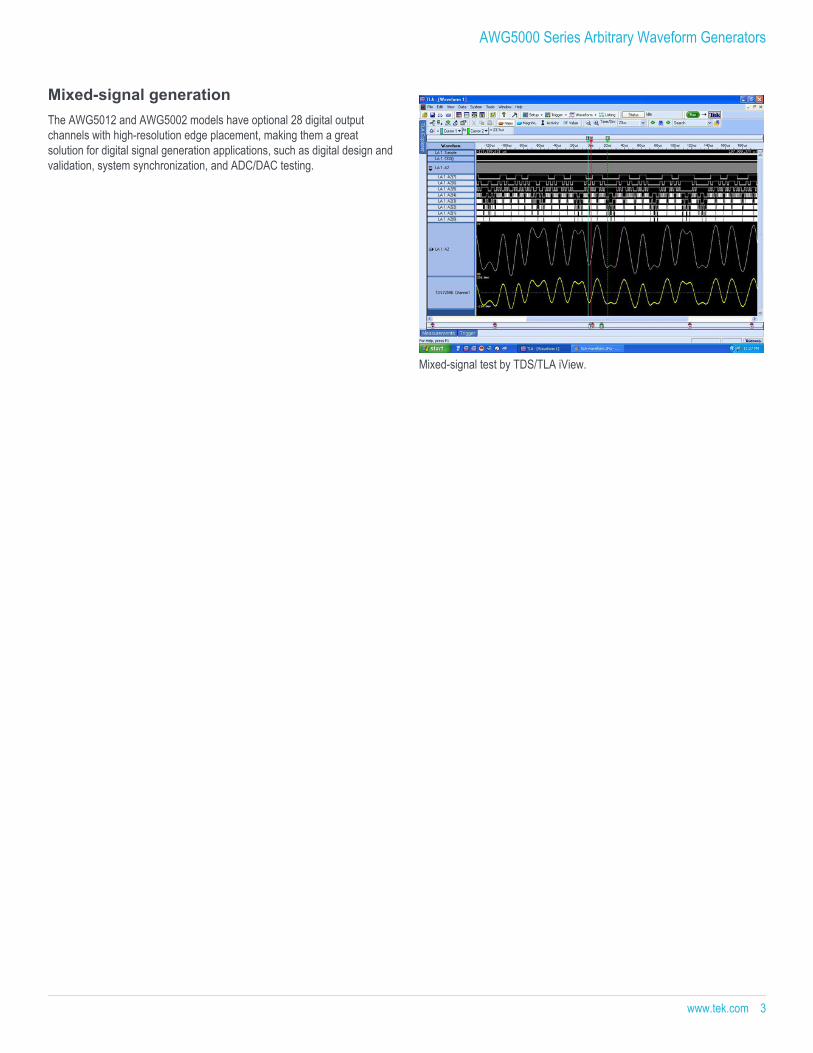
Mixed-signal generationThe AWG5012 and AWG5002 models have optional 28 digital outputchannels with high-resolution edge placement, making them a greatsolution for digital signal generation applications, such as digital design andvalidation, system synchronization, and ADC/DAC testing.
Mixed-signal test by TDS/TLA iView.
AWG5000 Series Arbitrary Waveform Generators
www.tek.com 3
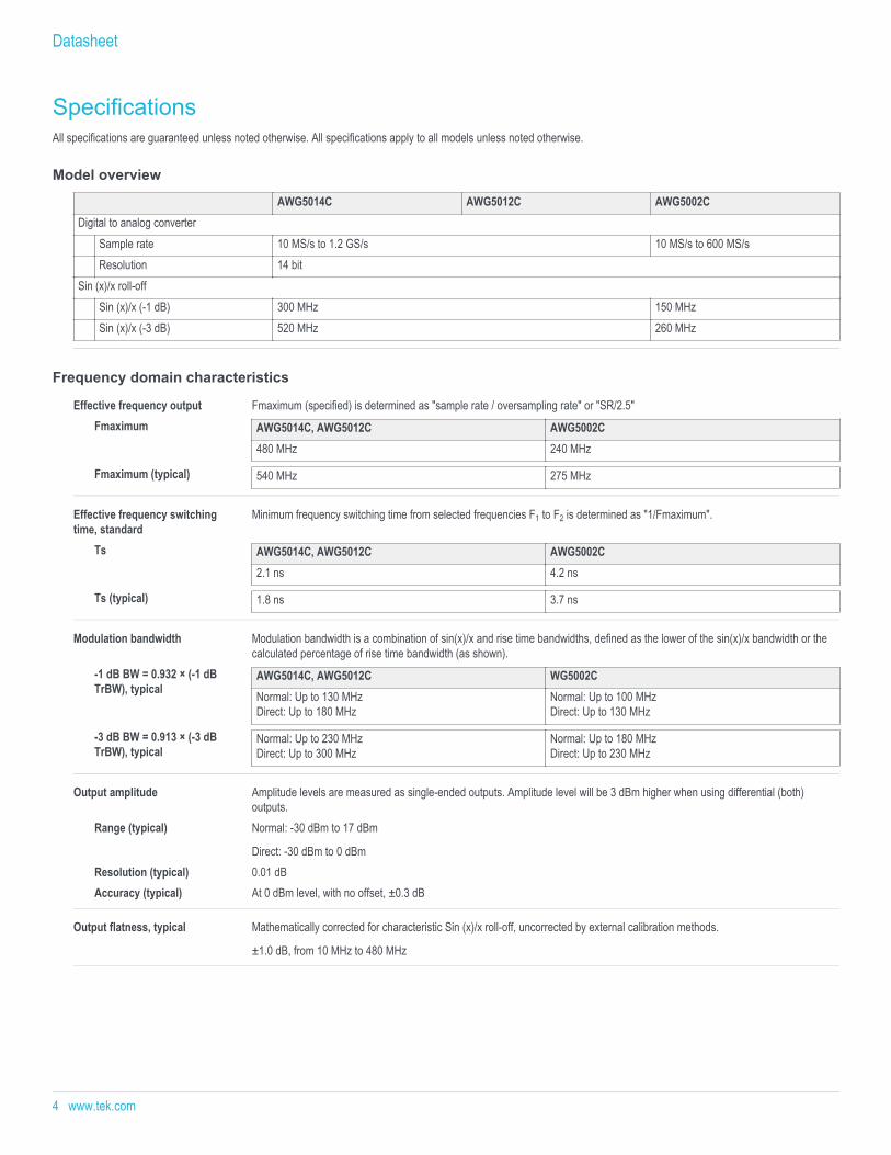
SpecificationsAll specifications are guaranteed unless noted otherwise. All specifications apply to all models unless noted otherwise.
Model overview
AWG5014C AWG5012C AWG5002CDigital to analog converter
Sample rate 10 MS/s to 1.2 GS/s 10 MS/s to 600 MS/sResolution 14 bit
Sin (x)/x roll-offSin (x)/x (-1 dB) 300 MHz 150 MHzSin (x)/x (-3 dB) 520 MHz 260 MHz
Frequency domain characteristics
Effective frequency output Fmaximum (specified) is determined as "sample rate / oversampling rate" or "SR/2.5"Fmaximum AWG5014C, AWG5012C AWG5002C
480 MHz 240 MHz
Fmaximum (typical) 540 MHz 275 MHz
Effective frequency switchingtime, standard
Minimum frequency switching time from selected frequencies F1 to F2 is determined as "1/Fmaximum".
Ts AWG5014C, AWG5012C AWG5002C2.1 ns 4.2 ns
Ts (typical) 1.8 ns 3.7 ns
Modulation bandwidth Modulation bandwidth is a combination of sin(x)/x and rise time bandwidths, defined as the lower of the sin(x)/x bandwidth or thecalculated percentage of rise time bandwidth (as shown).
-1 dB BW = 0.932 × (-1 dBTrBW), typical
AWG5014C, AWG5012C WG5002CNormal: Up to 130 MHzDirect: Up to 180 MHz
Normal: Up to 100 MHzDirect: Up to 130 MHz
-3 dB BW = 0.913 × (-3 dBTrBW), typical
Normal: Up to 230 MHzDirect: Up to 300 MHz
Normal: Up to 180 MHzDirect: Up to 230 MHz
Output amplitude Amplitude levels are measured as single-ended outputs. Amplitude level will be 3 dBm higher when using differential (both)outputs.
Range (typical) Normal: -30 dBm to 17 dBm
Direct: -30 dBm to 0 dBmResolution (typical) 0.01 dBAccuracy (typical) At 0 dBm level, with no offset, ±0.3 dB
Output flatness, typical Mathematically corrected for characteristic Sin (x)/x roll-off, uncorrected by external calibration methods.
±1.0 dB, from 10 MHz to 480 MHz
Datasheet
4 www.tek.com
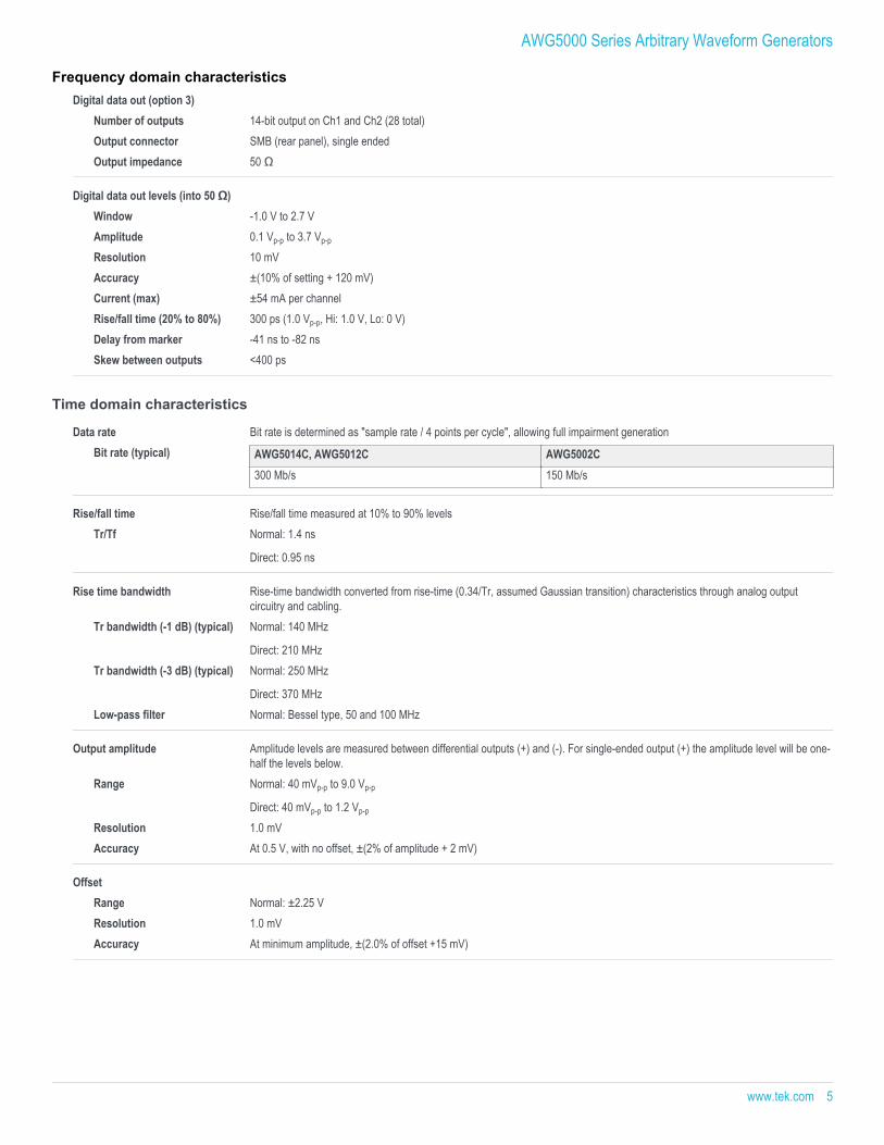
Digital data out (option 3)Number of outputs 14-bit output on Ch1 and Ch2 (28 total)Output connector SMB (rear panel), single endedOutput impedance 50 Ω
Digital data out levels (into 50 Ω)Window -1.0 V to 2.7 VAmplitude 0.1 Vp-p to 3.7 Vp-p
Resolution 10 mVAccuracy ±(10% of setting + 120 mV)Current (max) ±54 mA per channelRise/fall time (20% to 80%) 300 ps (1.0 Vp-p, Hi: 1.0 V, Lo: 0 V)Delay from marker -41 ns to -82 nsSkew between outputs <400 ps
Time domain characteristics
Data rate Bit rate is determined as "sample rate / 4 points per cycle", allowing full impairment generationBit rate (typical) AWG5014C, AWG5012C AWG5002C
300 Mb/s 150 Mb/s
Rise/fall time Rise/fall time measured at 10% to 90% levelsTr/Tf Normal: 1.4 ns
Direct: 0.95 ns
Rise time bandwidth Rise-time bandwidth converted from rise-time (0.34/Tr, assumed Gaussian transition) characteristics through analog outputcircuitry and cabling.
Tr bandwidth (-1 dB) (typical) Normal: 140 MHz
Direct: 210 MHzTr bandwidth (-3 dB) (typical) Normal: 250 MHz
Direct: 370 MHzLow-pass filter Normal: Bessel type, 50 and 100 MHz
Output amplitude Amplitude levels are measured between differential outputs (+) and (-). For single-ended output (+) the amplitude level will be one-half the levels below.
Range Normal: 40 mVp-p to 9.0 Vp-p
Direct: 40 mVp-p to 1.2 Vp-p
Resolution 1.0 mVAccuracy At 0.5 V, with no offset, ±(2% of amplitude + 2 mV)
OffsetRange Normal: ±2.25 VResolution 1.0 mVAccuracy At minimum amplitude, ±(2.0% of offset +15 mV)
AWG5000 Series Arbitrary Waveform Generators
Frequency domain characteristics
www.tek.com 5
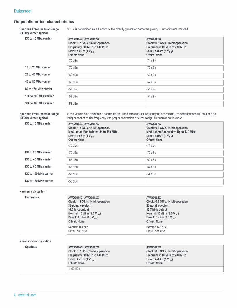
Output distortion characteristics
Spurious Free Dynamic Range(SFDR), direct, typical
SFDR is determined as a function of the directly generated carrier frequency. Harmonics not included
DC to 10 MHz carrier AWG5014C, AWG5012CClock: 1.2 GS/s, 14-bit operationFrequency: 10 MHz to 480 MHzLevel: 4 dBm (1 Vp-p)Offset: None
AWG5002CClock: 0.6 GS/s, 14-bit operationFrequency: 10 MHz to 240 MHzLevel: 4 dBm (1 Vp-p)Offset: None
-70 dBc -74 dBc
10 to 20 MHz carrier -70 dBc -70 dBc
20 to 40 MHz carrier -62 dBc -62 dBc
40 to 80 MHz carrier -62 dBc -57 dBc
80 to 150 MHz carrier -58 dBc -54 dBc
150 to 300 MHz carrier -58 dBc -54 dBc
300 to 480 MHz carrier -56 dBc
Spurious Free Dynamic Range(SFDR), direct, typical
When viewed as a modulation bandwidth and used with external frequency up-conversion, the specifications will hold and beindependent of carrier frequency with proper conversion circuitry design. Harmonics not included
DC to 10 MHz carrier AWG5014C, AWG5012CClock: 1.2 GS/s, 14-bit operationModulation Bandwidth: Up to 180 MHzLevel: 4 dBm (1 Vp-p)Offset: None
AWG5002CClock: 0.6 GS/s, 14-bit operationModulation Bandwidth: Up to 130 MHzLevel: 4 dBm (1 Vp-p)Offset: None
-70 dBc -74 dBc
DC to 20 MHz carrier -70 dBc -70 dBc
DC to 40 MHz carrier -62 dBc -62 dBc
DC to 80 MHz carrier -62 dBc -57 dBc
DC to 150 MHz carrier -58 dBc -54 dBc
DC to 180 MHz carrier -58 dBc
Harmonic distortionHarmonics AWG5014C, AWG5012C
Clock: 1.2 GS/s, 14-bit operation32-point waveform37.5 MHz outputNormal: 10 dBm (2.0 Vp-p)Direct: 0 dBm (0.6 Vp-p)Offset: None
AWG5002CClock: 0.6 GS/s, 14-bit operation32-point waveform18.7 MHz outputNormal: 10 dBm (2.0 Vp-p)Direct: 0 dBm (0.6 Vp-p)Offset: None
Normal: <40 dBcDirect: <49 dBc
Normal: <46 dBcDirect: <55 dBc
Non-harmonic distortionSpurious AWG5014C, AWG5012C
Clock: 1.2 GS/s, 14-bit operationFrequency: 10 MHz to 480 MHzLevel: 4 dBm (1 Vp-p)Offset: None
AWG5002CClock: 0.6 GS/s, 14-bit operationFrequency: 10 MHz to 240 MHzLevel: 4 dBm (1 Vp-p)Offset: None
< -60 dBc
Datasheet
6 www.tek.com
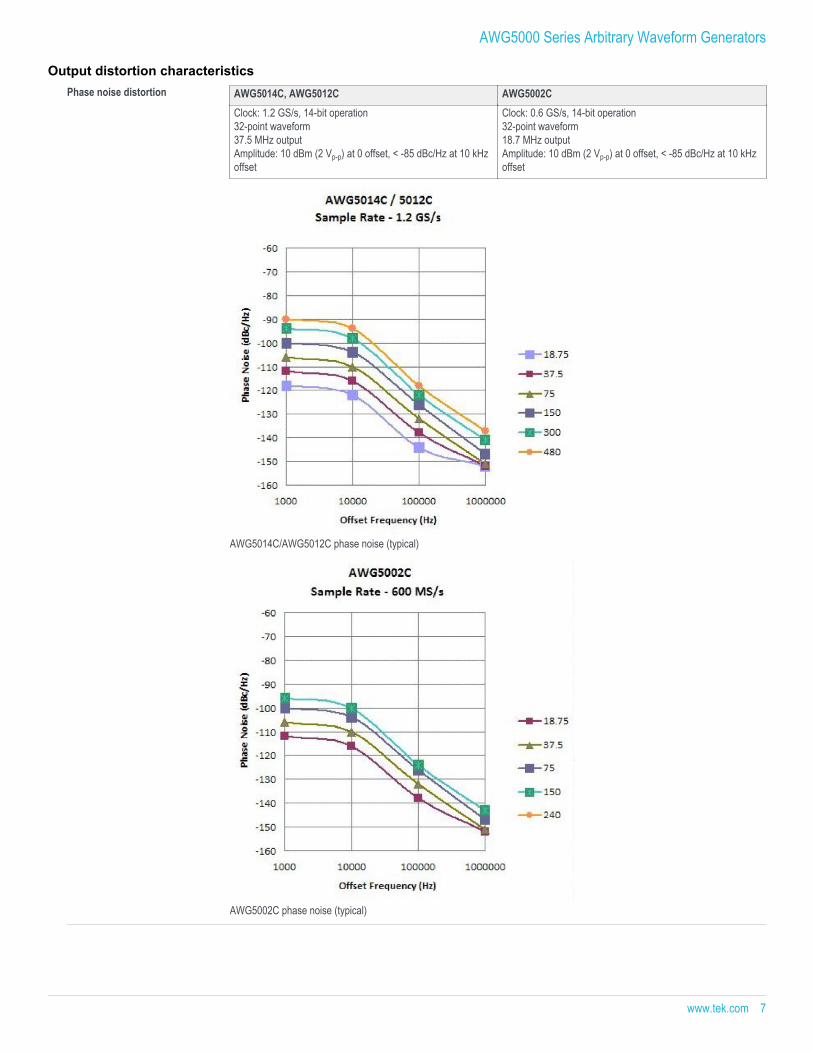
Phase noise distortion AWG5014C, AWG5012C AWG5002CClock: 1.2 GS/s, 14-bit operation32-point waveform37.5 MHz outputAmplitude: 10 dBm (2 Vp-p) at 0 offset, < -85 dBc/Hz at 10 kHzoffset
Clock: 0.6 GS/s, 14-bit operation32-point waveform18.7 MHz outputAmplitude: 10 dBm (2 Vp-p) at 0 offset, < -85 dBc/Hz at 10 kHzoffset
AWG5014C/AWG5012C phase noise (typical)
AWG5002C phase noise (typical)
AWG5000 Series Arbitrary Waveform Generators
Output distortion characteristics
www.tek.com 7
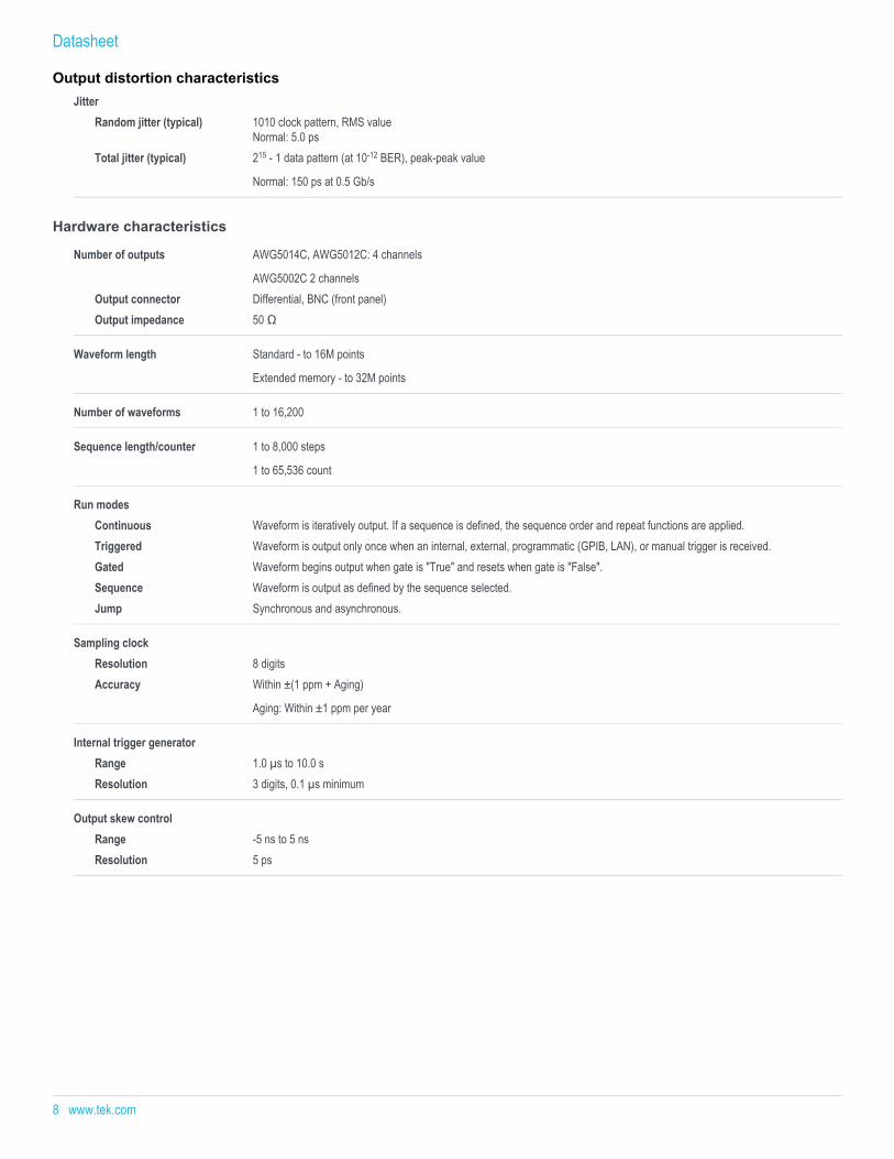
JitterRandom jitter (typical) 1010 clock pattern, RMS value
Normal: 5.0 psTotal jitter (typical) 215 - 1 data pattern (at 10-12 BER), peak-peak value
Normal: 150 ps at 0.5 Gb/s
Hardware characteristics
Number of outputs AWG5014C, AWG5012C: 4 channels
AWG5002C 2 channelsOutput connector Differential, BNC (front panel)Output impedance 50 Ω
Waveform length Standard - to 16M points
Extended memory - to 32M points
Number of waveforms 1 to 16,200
Sequence length/counter 1 to 8,000 steps
1 to 65,536 count
Run modesContinuous Waveform is iteratively output. If a sequence is defined, the sequence order and repeat functions are applied.Triggered Waveform is output only once when an internal, external, programmatic (GPIB, LAN), or manual trigger is received.Gated Waveform begins output when gate is "True" and resets when gate is "False".Sequence Waveform is output as defined by the sequence selected.Jump Synchronous and asynchronous.
Sampling clockResolution 8 digitsAccuracy Within ±(1 ppm + Aging)
Aging: Within ±1 ppm per year
Internal trigger generatorRange 1.0 µs to 10.0 sResolution 3 digits, 0.1 µs minimum
Output skew controlRange -5 ns to 5 nsResolution 5 ps
Datasheet
Output distortion characteristics
8 www.tek.com
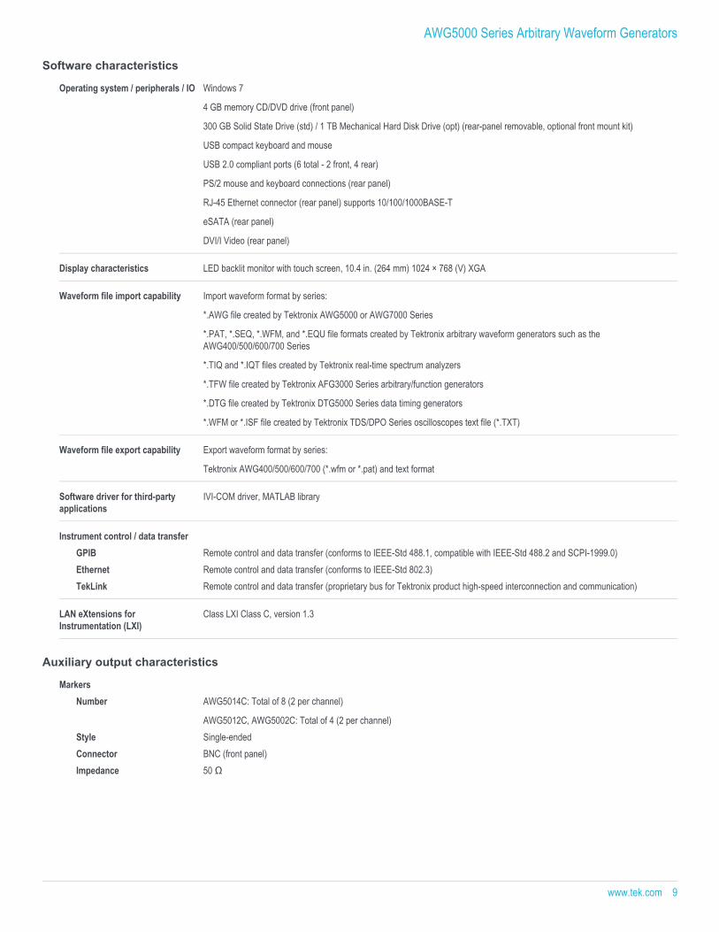
Software characteristics
Operating system / peripherals / IO Windows 7
4 GB memory CD/DVD drive (front panel)
300 GB Solid State Drive (std) / 1 TB Mechanical Hard Disk Drive (opt) (rear-panel removable, optional front mount kit)
USB compact keyboard and mouse
USB 2.0 compliant ports (6 total - 2 front, 4 rear)
PS/2 mouse and keyboard connections (rear panel)
RJ-45 Ethernet connector (rear panel) supports 10/100/1000BASE-T
eSATA (rear panel)
DVI/I Video (rear panel)
Display characteristics LED backlit monitor with touch screen, 10.4 in. (264 mm) 1024 × 768 (V) XGA
Waveform file import capability Import waveform format by series:
*.AWG file created by Tektronix AWG5000 or AWG7000 Series
*.PAT, *.SEQ, *.WFM, and *.EQU file formats created by Tektronix arbitrary waveform generators such as theAWG400/500/600/700 Series
*.TIQ and *.IQT files created by Tektronix real-time spectrum analyzers
*.TFW file created by Tektronix AFG3000 Series arbitrary/function generators
*.DTG file created by Tektronix DTG5000 Series data timing generators
*.WFM or *.ISF file created by Tektronix TDS/DPO Series oscilloscopes text file (*.TXT)
Waveform file export capability Export waveform format by series:
Tektronix AWG400/500/600/700 (*.wfm or *.pat) and text format
Software driver for third-partyapplications
IVI-COM driver, MATLAB library
Instrument control / data transferGPIB Remote control and data transfer (conforms to IEEE-Std 488.1, compatible with IEEE-Std 488.2 and SCPI-1999.0)Ethernet Remote control and data transfer (conforms to IEEE-Std 802.3)TekLink Remote control and data transfer (proprietary bus for Tektronix product high-speed interconnection and communication)
LAN eXtensions forInstrumentation (LXI)
Class LXI Class C, version 1.3
Auxiliary output characteristics
MarkersNumber AWG5014C: Total of 8 (2 per channel)
AWG5012C, AWG5002C: Total of 4 (2 per channel)Style Single-endedConnector BNC (front panel)Impedance 50 Ω
AWG5000 Series Arbitrary Waveform Generators
www.tek.com 9
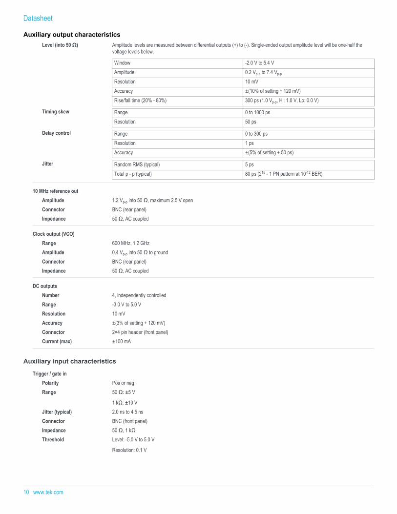
Level (into 50 Ω) Amplitude levels are measured between differential outputs (+) to (-). Single-ended output amplitude level will be one-half thevoltage levels below.
Window -2.0 V to 5.4 VAmplitude 0.2 Vp-p to 7.4 Vp-p
Resolution 10 mVAccuracy ±(10% of setting + 120 mV)Rise/fall time (20% - 80%) 300 ps (1.0 Vp-p, Hi: 1.0 V, Lo: 0.0 V)
Timing skew Range 0 to 1000 psResolution 50 ps
Delay control Range 0 to 300 psResolution 1 psAccuracy ±(5% of setting + 50 ps)
Jitter Random RMS (typical) 5 psTotal p - p (typical) 80 ps (215 - 1 PN pattern at 10-12 BER)
10 MHz reference outAmplitude 1.2 Vp-p into 50 Ω, maximum 2.5 V openConnector BNC (rear panel)Impedance 50 Ω, AC coupled
Clock output (VCO)Range 600 MHz, 1.2 GHzAmplitude 0.4 Vp-p into 50 Ω to groundConnector BNC (rear panel)Impedance 50 Ω, AC coupled
DC outputsNumber 4, independently controlledRange -3.0 V to 5.0 VResolution 10 mVAccuracy ±(3% of setting + 120 mV)Connector 2×4 pin header (front panel)Current (max) ±100 mA
Auxiliary input characteristics
Trigger / gate inPolarity Pos or negRange 50 Ω: ±5 V
1 kΩ: ±10 VJitter (typical) 2.0 ns to 4.5 nsConnector BNC (front panel)Impedance 50 Ω, 1 kΩThreshold Level: -5.0 V to 5.0 V
Resolution: 0.1 V
Datasheet
Auxiliary output characteristics
10 www.tek.com
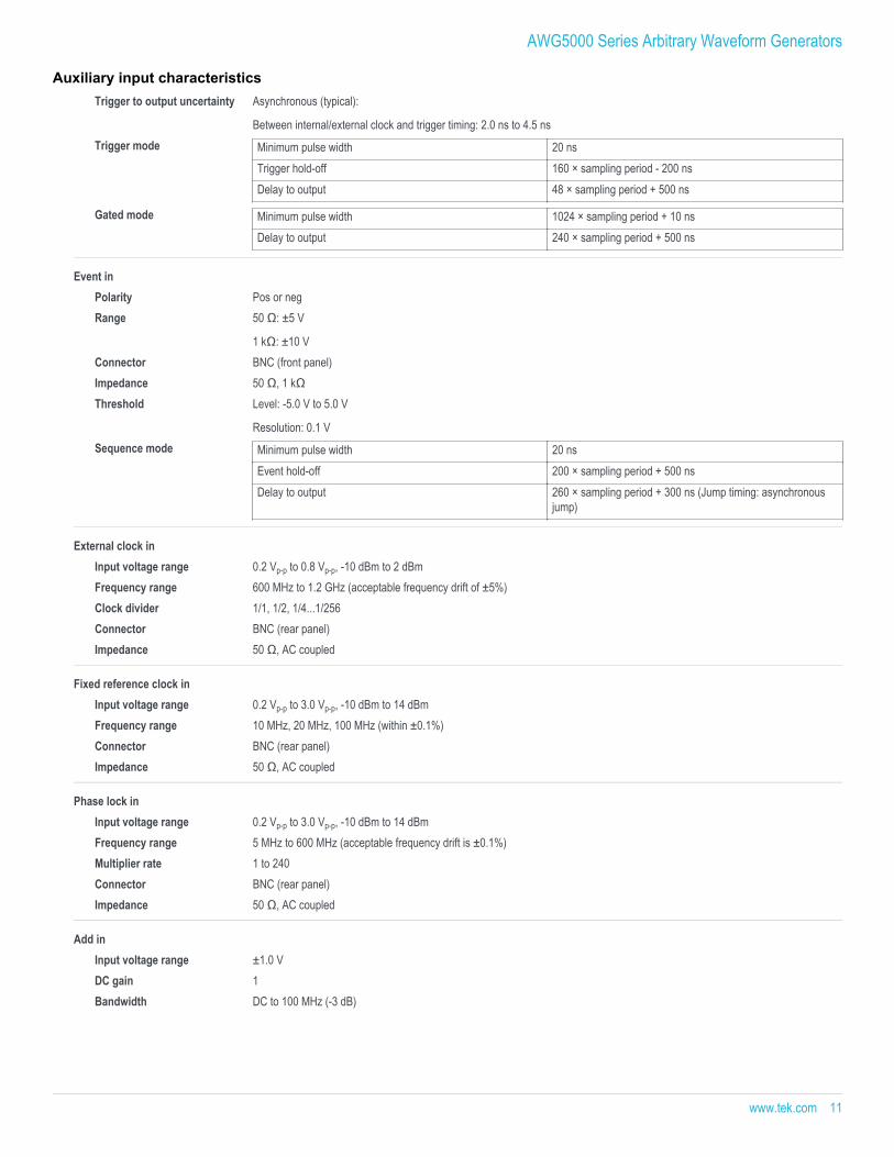
Trigger to output uncertainty Asynchronous (typical):
Between internal/external clock and trigger timing: 2.0 ns to 4.5 nsTrigger mode Minimum pulse width 20 ns
Trigger hold-off 160 × sampling period - 200 nsDelay to output 48 × sampling period + 500 ns
Gated mode Minimum pulse width 1024 × sampling period + 10 nsDelay to output 240 × sampling period + 500 ns
Event inPolarity Pos or negRange 50 Ω: ±5 V
1 kΩ: ±10 VConnector BNC (front panel)Impedance 50 Ω, 1 kΩThreshold Level: -5.0 V to 5.0 V
Resolution: 0.1 VSequence mode Minimum pulse width 20 ns
Event hold-off 200 × sampling period + 500 nsDelay to output 260 × sampling period + 300 ns (Jump timing: asynchronous
jump)
External clock inInput voltage range 0.2 Vp-p to 0.8 Vp-p, -10 dBm to 2 dBmFrequency range 600 MHz to 1.2 GHz (acceptable frequency drift of ±5%)Clock divider 1/1, 1/2, 1/4...1/256 Connector BNC (rear panel)Impedance 50 Ω, AC coupled
Fixed reference clock inInput voltage range 0.2 Vp-p to 3.0 Vp-p, -10 dBm to 14 dBmFrequency range 10 MHz, 20 MHz, 100 MHz (within ±0.1%)Connector BNC (rear panel)Impedance 50 Ω, AC coupled
Phase lock inInput voltage range 0.2 Vp-p to 3.0 Vp-p, -10 dBm to 14 dBmFrequency range 5 MHz to 600 MHz (acceptable frequency drift is ±0.1%)Multiplier rate 1 to 240 Connector BNC (rear panel)Impedance 50 Ω, AC coupled
Add inInput voltage range ±1.0 VDC gain 1 Bandwidth DC to 100 MHz (-3 dB)
AWG5000 Series Arbitrary Waveform Generators
Auxiliary input characteristics
www.tek.com 11
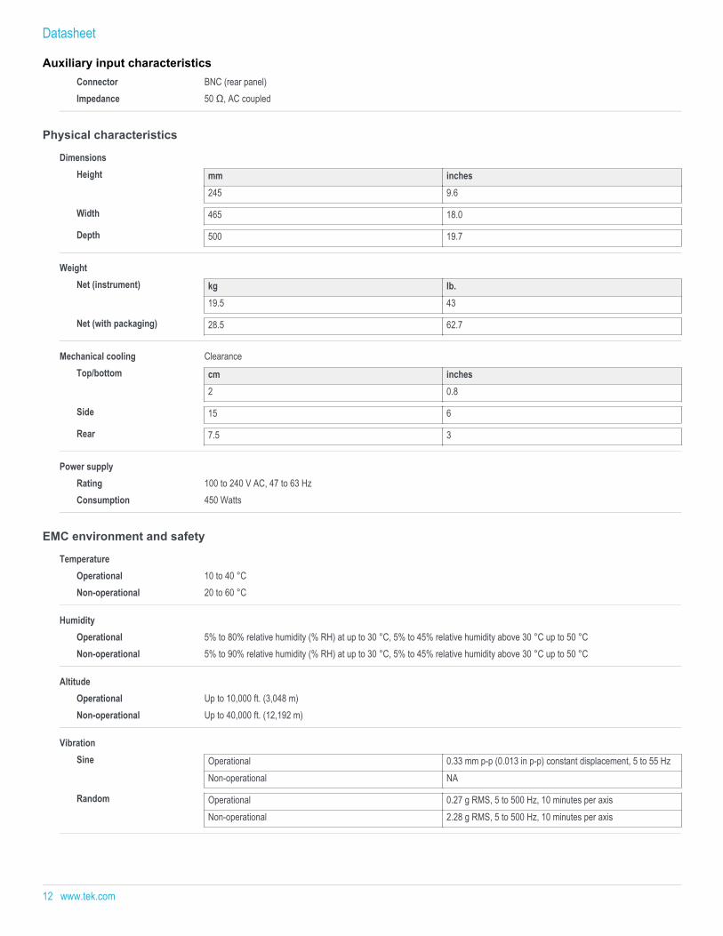
Connector BNC (rear panel)Impedance 50 Ω, AC coupled
Physical characteristics
DimensionsHeight mm inches
245 9.6
Width 465 18.0
Depth 500 19.7
WeightNet (instrument) kg lb.
19.5 43
Net (with packaging) 28.5 62.7
Mechanical cooling ClearanceTop/bottom cm inches
2 0.8
Side 15 6
Rear 7.5 3
Power supplyRating 100 to 240 V AC, 47 to 63 HzConsumption 450 Watts
EMC environment and safety
TemperatureOperational 10 to 40 °CNon-operational 20 to 60 °C
HumidityOperational 5% to 80% relative humidity (% RH) at up to 30 °C, 5% to 45% relative humidity above 30 °C up to 50 °CNon-operational 5% to 90% relative humidity (% RH) at up to 30 °C, 5% to 45% relative humidity above 30 °C up to 50 °C
AltitudeOperational Up to 10,000 ft. (3,048 m)Non-operational Up to 40,000 ft. (12,192 m)
VibrationSine Operational 0.33 mm p-p (0.013 in p-p) constant displacement, 5 to 55 Hz
Non-operational NA
Random Operational 0.27 g RMS, 5 to 500 Hz, 10 minutes per axisNon-operational 2.28 g RMS, 5 to 500 Hz, 10 minutes per axis
Datasheet
Auxiliary input characteristics
12 www.tek.com
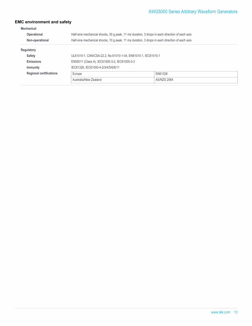
MechanicalOperational Half-sine mechanical shocks, 30 g peak, 11 ms duration, 3 drops in each direction of each axisNon-operational Half-sine mechanical shocks, 10 g peak, 11 ms duration, 3 drops in each direction of each axis
RegulatorySafety UL61010-1, CAN/CSA-22.2, No.61010-1-04, EN61010-1, IEC61010-1 Emissions EN55011 (Class A), IEC61000-3-2, IEC61000-3-3 Immunity IEC61326, IEC61000-4-2/3/4/5/6/8/11 Regional certifications Europe EN61326
Australia/New Zealand AS/NZS 2064
AWG5000 Series Arbitrary Waveform Generators
EMC environment and safety
www.tek.com 13
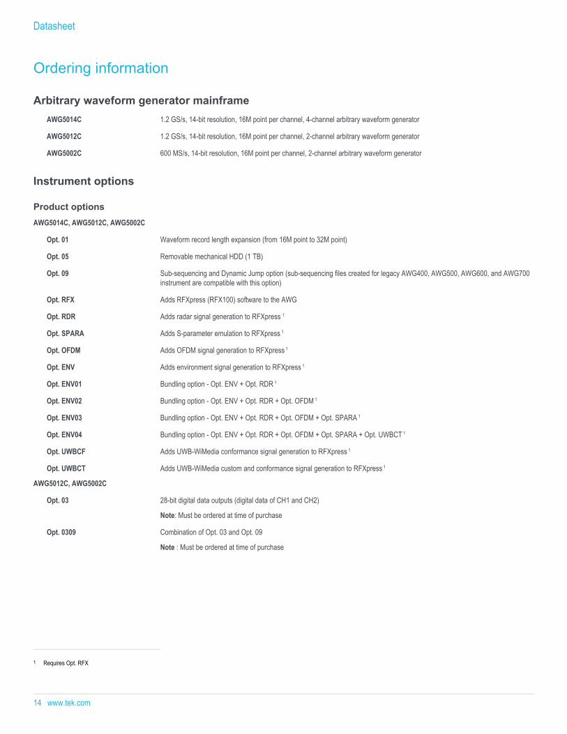
Ordering information
Arbitrary waveform generator mainframeAWG5014C 1.2 GS/s, 14-bit resolution, 16M point per channel, 4-channel arbitrary waveform generator
AWG5012C 1.2 GS/s, 14-bit resolution, 16M point per channel, 2-channel arbitrary waveform generator
AWG5002C 600 MS/s, 14-bit resolution, 16M point per channel, 2-channel arbitrary waveform generator
Instrument options
Product optionsAWG5014C, AWG5012C, AWG5002C
Opt. 01 Waveform record length expansion (from 16M point to 32M point)
Opt. 05 Removable mechanical HDD (1 TB)
Opt. 09 Sub-sequencing and Dynamic Jump option (sub-sequencing files created for legacy AWG400, AWG500, AWG600, and AWG700instrument are compatible with this option)
Opt. RFX Adds RFXpress (RFX100) software to the AWG
Opt. RDR Adds radar signal generation to RFXpress 1
Opt. SPARA Adds S-parameter emulation to RFXpress 1
Opt. OFDM Adds OFDM signal generation to RFXpress 1
Opt. ENV Adds environment signal generation to RFXpress 1
Opt. ENV01 Bundling option - Opt. ENV + Opt. RDR 1
Opt. ENV02 Bundling option - Opt. ENV + Opt. RDR + Opt. OFDM 1
Opt. ENV03 Bundling option - Opt. ENV + Opt. RDR + Opt. OFDM + Opt. SPARA 1
Opt. ENV04 Bundling option - Opt. ENV + Opt. RDR + Opt. OFDM + Opt. SPARA + Opt. UWBCT 1
Opt. UWBCF Adds UWB-WiMedia conformance signal generation to RFXpress 1
Opt. UWBCT Adds UWB-WiMedia custom and conformance signal generation to RFXpress 1
AWG5012C, AWG5002C
Opt. 03 28-bit digital data outputs (digital data of CH1 and CH2)
Note: Must be ordered at time of purchase
Opt. 0309 Combination of Opt. 03 and Opt. 09
Note : Must be ordered at time of purchase
1 Requires Opt. RFX
Datasheet
14 www.tek.com
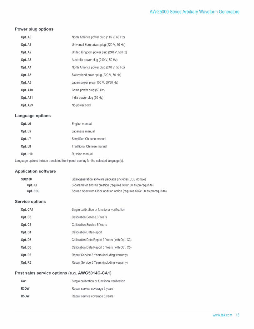
Power plug options
Opt. A0 North America power plug (115 V, 60 Hz)
Opt. A1 Universal Euro power plug (220 V, 50 Hz)
Opt. A2 United Kingdom power plug (240 V, 50 Hz)
Opt. A3 Australia power plug (240 V, 50 Hz)
Opt. A4 North America power plug (240 V, 50 Hz)
Opt. A5 Switzerland power plug (220 V, 50 Hz)
Opt. A6 Japan power plug (100 V, 50/60 Hz)
Opt. A10 China power plug (50 Hz)
Opt. A11 India power plug (50 Hz)
Opt. A99 No power cord
Language options
Opt. L0 English manual
Opt. L5 Japanese manual
Opt. L7 Simplified Chinese manual
Opt. L8 Traditional Chinese manual
Opt. L10 Russian manual
Language options include translated front-panel overlay for the selected language(s).
Application software
SDX100 Jitter-generation software package (includes USB dongle)Opt. ISI S-parameter and ISI creation (requires SDX100 as prerequisite)Opt. SSC Spread Spectrum Clock addition option (requires SDX100 as prerequisite)
Service options
Opt. CA1 Single calibration or functional verification
Opt. C3 Calibration Service 3 Years
Opt. C5 Calibration Service 5 Years
Opt. D1 Calibration Data Report
Opt. D3 Calibration Data Report 3 Years (with Opt. C3)
Opt. D5 Calibration Data Report 5 Years (with Opt. C5)
Opt. R3 Repair Service 3 Years (including warranty)
Opt. R5 Repair Service 5 Years (including warranty)
Post sales service options (e.g. AWG5014C-CA1)
CA1 Single calibration or functional verification
R3DW Repair service coverage 3 years
R5DW Repair service coverage 5 years
AWG5000 Series Arbitrary Waveform Generators
www.tek.com 15
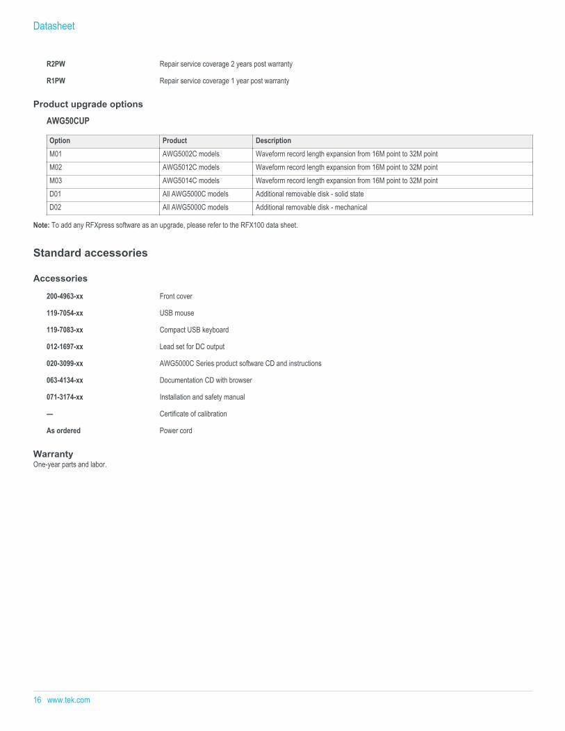
R2PW Repair service coverage 2 years post warranty
R1PW Repair service coverage 1 year post warranty
Product upgrade options
AWG50CUP
Option Product DescriptionM01 AWG5002C models Waveform record length expansion from 16M point to 32M pointM02 AWG5012C models Waveform record length expansion from 16M point to 32M pointM03 AWG5014C models Waveform record length expansion from 16M point to 32M pointD01 All AWG5000C models Additional removable disk - solid stateD02 All AWG5000C models Additional removable disk - mechanical
Note: To add any RFXpress software as an upgrade, please refer to the RFX100 data sheet.
Standard accessories
Accessories
200-4963-xx Front cover
119-7054-xx USB mouse
119-7083-xx Compact USB keyboard
012-1697-xx Lead set for DC output
020-3099-xx AWG5000C Series product software CD and instructions
063-4134-xx Documentation CD with browser
071-3174-xx Installation and safety manual
— Certificate of calibration
As ordered Power cord
WarrantyOne-year parts and labor.
Datasheet
16 www.tek.com
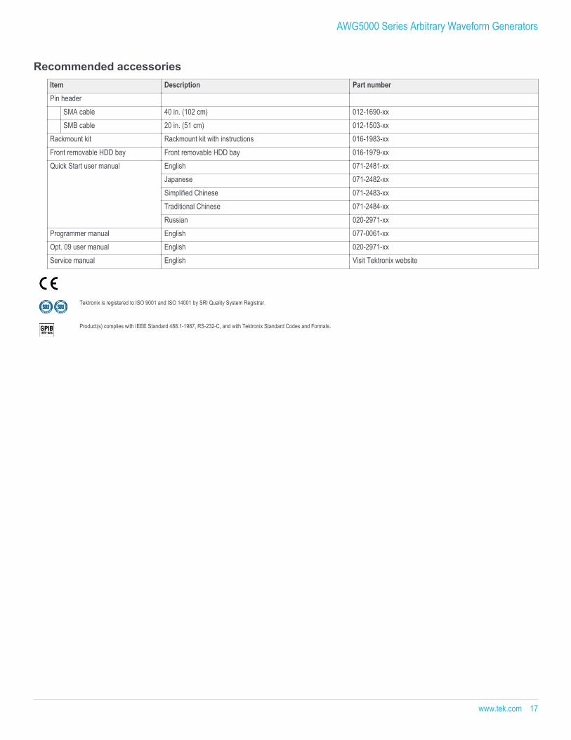
Recommended accessoriesItem Description Part numberPin header
SMA cable 40 in. (102 cm) 012-1690-xxSMB cable 20 in. (51 cm) 012-1503-xx
Rackmount kit Rackmount kit with instructions 016-1983-xxFront removable HDD bay Front removable HDD bay 016-1979-xxQuick Start user manual English 071-2481-xx
Japanese 071-2482-xxSimplified Chinese 071-2483-xxTraditional Chinese 071-2484-xxRussian 020-2971-xx
Programmer manual English 077-0061-xxOpt. 09 user manual English 020-2971-xxService manual English Visit Tektronix website
Tektronix is registered to ISO 9001 and ISO 14001 by SRI Quality System Registrar.
Product(s) complies with IEEE Standard 488.1-1987, RS-232-C, and with Tektronix Standard Codes and Formats.
AWG5000 Series Arbitrary Waveform Generators
www.tek.com 17
Datasheet
ASEAN / Australasia (65) 6356 3900 Austria 00800 2255 4835* Balkans, Israel, South Africa and other ISE Countries +41 52 675 3777 Belgium 00800 2255 4835* Brazil +55 (11) 3759 7627 Canada 1 800 833 9200 Central East Europe and the Baltics +41 52 675 3777 Central Europe & Greece +41 52 675 3777 Denmark +45 80 88 1401 Finland +41 52 675 3777 France 00800 2255 4835* Germany 00800 2255 4835*Hong Kong 400 820 5835 India 000 800 650 1835 Italy 00800 2255 4835*Japan 81 (3) 6714 3010 Luxembourg +41 52 675 3777 Mexico, Central/South America & Caribbean 52 (55) 56 04 50 90 Middle East, Asia, and North Africa +41 52 675 3777 The Netherlands 00800 2255 4835* Norway 800 16098 People's Republic of China 400 820 5835 Poland +41 52 675 3777 Portugal 80 08 12370 Republic of Korea +822 6917 5084, 822 6917 5080 Russia & CIS +7 (495) 6647564 South Africa +41 52 675 3777 Spain 00800 2255 4835* Sweden 00800 2255 4835* Switzerland 00800 2255 4835*Taiwan 886 (2) 2656 6688 United Kingdom & Ireland 00800 2255 4835* USA 1 800 833 9200
* European toll-free number. If not accessible, call: +41 52 675 3777
For Further Information. Tektronix maintains a comprehensive, constantly expanding collection of application notes, technical briefs and other resources to help engineers working on the cutting edge of technology. Please visit www.tek.com.
Copyright © Tektronix, Inc. All rights reserved. Tektronix products are covered by U.S. and foreign patents, issued and pending. Information in this publication supersedes that in all previously published material. Specification andprice change privileges reserved. TEKTRONIX and TEK are registered trademarks of Tektronix, Inc. All other trade names referenced are the service marks, trademarks, or registered trademarks of their respective companies.
25 Jul 2016 76W-22260-13
www.tek.com