Embed Size (px)
Citation preview

Architectural and Engineering
Design Standards
Capital Management Department
University of Iowa Hospitals & Clinics
Revision 14: December 30, 2017

Rev. 14 December 30, 2017
Page | 2
INTRODUCTION
This document has been prepared to assist Design Professionals preparing professional services in the design,
construction and maintenance of UIHC Facilities. This document has been reviewed and approved by a Standards
Oversight Committee made up of UIHC representatives from Capital Management, Maintenance/Engineering,
Communication Technology Services, Respiratory Therapy, Epidemiology, Ancillary Services, Guest
Services/Housekeeping, and Safety & Security.
Preferred materials guidelines have been selected on the basis of extensive analysis. However, the most important
guideline in the selection of construction materials is the strict compliance with mandatory building codes and industry
reference standards. There may be particular circumstances in which, in the judgment of the Design Professional, cost
effective viable alternatives are warranted. We welcome such recommendations and will consider each one of them
carefully prior to implementation. As a part of the design process, the Design Professional shall submit in writing
rationale for areas where specified manufacturers or products are not being utilized. Those instances require Owner
approval. A form has been provided in Appendix K, and shall be filled in by the Design Professional. The
completed form shall be returned to the Owner for approval during design.
The University of Iowa Hospitals & Clinics incorporates green principles in the placement, design and construction
of new facilities and major renovation projects, targeting a minimum standard of Leadership in Energy and
Environmental Design (LEED) Silver certification. Major project is defined as a facility over 20,000 gross square feet.
A major capital renovation is defined as a construction budget that will cost more than 50% of the facility’s
replacement value. UIHC accomplishes this certification by focusing on the ecological, social and economic
performance of each project. Design Professionals are required to adhere to these principles and strive for
sustainability in all designs. This document will be updated periodically. Updates to this standard will only be
made after careful consideration by members of the UIHC Standards Oversight Committee. A procedure has been
developed for formal application of changes to the standard. Contact the Capital Management Department for the
applicable forms.
Use of this standard does not relieve the Design Professional from adhering to engineering practices, applicable
codes, etc. Where there is a conflict between the contents of these standard and applicable codes that which is more
stringent will take precedence.

Rev. 14 December 30, 2017
Page | 3
This page is intentionally left blank.
Rev. 14 December 30, 2017
Page | 4
Table of Contents 1. GENERAL REQUIREMENTS .................................................................................................................................................. 9
1.1 Application of Design Standards ................................................................................................................................ 9
1.2 Applicable Documents................................................................................................................................................ 9
1.2.1 Building Codes and Standards ............................................................................................................................. 9
1.2.2 Reference Documents ................................................................................................................................... 10
1.3 Risk Assessment/Infection Control .......................................................................................................................... 12
1.4 Site Design Considerations ...................................................................................................................................... 12
1.5 Utility Energy Incentives .......................................................................................................................................... 12
1.6 Existing Hospital Finishes ......................................................................................................................................... 12
2. DESIGN DELIVERABLES.................................................................................................................................................... 14
2.1 Design Deliverable Requirements ............................................................................................................................ 14
2.1.1 State of Iowa Board of Regents Submissions .................................................................................................... 14
2.1.2 Schematic Design .............................................................................................................................................. 14
2.1.3 Design Development ......................................................................................................................................... 16
2.1.4 Construction Document ................................................................................................................................ 19
2.1.5 Record Documents ............................................................................................................................................ 22
2.1.6 FM Global Roof Compliance Process ................................................................................................................. 23
3. DRAWINGS & SPECIFICATIONS ........................................................................................................................................ 25
3.1 UIHC Room Numbering ............................................................................................................................................ 25
4. ARCHITECTURAL & ENGINEERING STANDARDS ............................................................................................................. 26
4.1 Division 01 – General Requirements..................................................................................................................... 26
4.2 Division 02 – Existing Conditions ............................................................................................................................. 27
4.3 Division 03– Concrete .............................................................................................................................................. 28
4.4 Division 04 - Masonry .............................................................................................................................................. 29
4.5 Division 05 – Metals ................................................................................................................................................. 29
4.6 Division 06 – Wood and Plastics ............................................................................................................................... 29
4.7 Division 07 – Thermal and Moisture Protection ..................................................................................................... 31
4.8 Division 08 – Openings ............................................................................................................................................ 35
4.9 Division 09 – Finishes .............................................................................................................................................. 39
4.10 Division 10 – Specialties .......................................................................................................................................... 41
4.11 Division 11 – Equipment for Roof Standards Update ............................................................................................. 44
Rev. 14 December 30, 2017
Page | 5
4.12 Division 12 – Furnishings ......................................................................................................................................... 45
4.13 Division 13 – Special Construction .......................................................................................................................... 45
4.14 Division 14 – Conveying Equipment ........................................................................................................................ 46
4.15 Division 21 – Fire Suppression ................................................................................................................................ 46
4.16 Division 22 – Plumbing ............................................................................................................................................ 49
4.17 Division 23 – Heating, Ventilation, and Air-Conditioning (HVAC) ........................................................................... 60
4.18 Division 26 – Electrical ............................................................................................................................................. 75
4.19 Division 27 – Communications ................................................................................................................................ 91
4.20 Division 28 – Electronic Safety and Security ........................................................................................................... 92
4.21 Division 32 – Exterior Improvements ...................................................................................................................... 95
4.22 Division 41 – Material Processing & Holding Equipment ........................................................................................ 95
Rev. 14 December 30, 2017
Page | 6
Revision Date Description 13 11/01/16 Updated cover photo
Replaced with Capital Management Logo
Updated introduction
Updated General Requirements, Sections 1.2 & 1.2.1
Updated 1.2.2.6 Casework Standards
Updated 1.3 Risk Assessment/ Infection Control
Removed 1.5 Safety Considerations
Updated 1.7 Existing Hospital Finishes
Updated 2.1.2 Schematic Design Written Requirements Section
Updated 2.1.3 Design Development Written Requirements Section
Updated 2.1.4 Construction Document paragraph and Written Requirements and Drawing
Requirements
Updated FM Global contact to Tom Lauer; Section 2.1.6
Updated Construction-Phase Process Section
Removed Section 3.2 UIHC Standardized Details (3.2.1 & 3.2.2)
Updated Section 01 78 36; Warranties
Updated 4.2 Division 02- Existing Conditions; Added line 3
Updated 05 51 14 Prefabricated Metal Roof Access Ladders
Updated 06 20 00 Finish Carpentry
Updated 06 60 00 Solid Surfaces; Added lines 5, 6 & 7
Updated 4.7 Division 07 – Thermal and Moisture Protection
Added Building Insulation; 07 20 00
Updated 07 50 00 Membrane Roofing
Updated 07 54 19.02 Adhered PVC Thermoplastic Membrane Roofing
Updated 07 81 00 Fireproofing
Updated 4.8 Division 08 – Openings: Notes Section
Updated 08 12 00 Steel Door Frames
Updated 08 13 00 Hollow Metal Flush Doors
Updated 08 14 00 Flush Wood Doors; added line 9
Updated 08 31 00 Fire Rated Access Doors
Updated 08 33 23 Rolling Fire Doors
Updated 08 71 00 Door Hardware; Added line 8
Updated 08 74 00 Access Control Hardware
Updated 08 80 00 Glass and Glazing; added line 6
Updated 09 22 16 Non-Load Bearing Partition Framing
Updated 09 29 00 Gypsum Wallboard; updates to line 1
Removed 09 63 00 Masonry Flooring
Updated 09 65 16 Resilient Sheet Flooring
Added line 3 to Painting and Coding; 09 90 00
Added section Rolled Carpet; 09 68 16
Added section Acoustical Ceilings; 09 50 00
Added section Epoxy Quartz Flooring; 09 72 50
Added line 2 to Epoxy Paint; 09 96 56
Added section Signage; 10 14 00
Added section Corner Guards; 10 26 00
Updated 10 26 33 Kickplates
Added section Fire Extinguisher Cabinets; 10 44 00
Updated 10 90 00 Miscellaneous Specialties; added line 3
Removed Section 11 28 13 Computers
Added section Roller Shades; 12 24 13
Updated 21 12 26 Fire Surpression Valve and Hose Cabinets
Updated 21 13 13 Wet-Pipe Automatic Sprinkler System; added line 8
Updated 23 05 53 Identification for HVAC Piping and Equipment
Added line 6 to 22 60 00 Gas and Vacuum Systems for Lab and Healthcare Facilities
Updated 23 09 00; Line 4 TSI Model Pressura RPM10
Added section Eye Wash; 22 45 19
Updated 26 05 33 Raceway and Boxes for Electrical Systems; EMT/Ridged (added Ridged)
Added section Wiring Devices; 26 27 26
Added Appendix M “Capital Management Design Process”
Rev. 14 December 30, 2017
Page | 7
Revision Date Description 13 14
11/01/16 12/30/2017
Updated Appendix E - UIHC Infection Control Specification (Section 01515)
Updated Section 4.19 – Updates to Division 27 added as Appendix
Added Appendix N – Division 27 – Communications
Updated cover photo
Updated 1.2.1 Building Codes and Standards
Removed note from 1.2.1 Building Codes and Standards
Added line to 1.2.1 Licensed Healthcare Facilities
Added line to 1.2.1 State Owned Facilities
Updated section 1.3 Risk Assessment/ Infection control
Removed line 1) D. from section 2.1.2 Schematic Design
Updated section 2.1.4 Item C. Line vii. To include space before “TAB locations”
Updated section 06 20 00 line 1. On Casework
Moved section 07 21 29 Spray Foam insulation below section 4.7 Division 07 after 07 20 00
Edited section 07 84 00 Firestopping under 1.) line item C., added line item ii.
Added line F under section 07 84 00 item 3.) under firestopping Scope/Application
Added “over 84” high) to Section 4.8 08 12 00 Steel Door Frames line item 2.
Added “over 84” high” to section 4.8 under 08 13 00 line item 2.
Added line item 8 to section 4.8 under 08 13 00
Added line item C to section 1 of 08 51 13 Aluminum Windows
Edited line item 9 under section 08 71 00 Door Hardware to HG325
Edited line item 10 under section C 08 71 00 Door Hardware
Edited line item 17 under Section C 08 71 00 Door Hardware
Updated line item 32. Under section C 08 71 00 Door Hardware, deleted “harmony”
Updated line item 34 under section C 08 71 00 Door Hardware to include E500 Series
Updated line item 37 under section C 08 71 00 Door Hardware
Edited section 4.9 Division 09- Finishes section 09 29 00 Gypsum Wallboard line 3.
Deleted redundant section 09 65 16 Resilient Sheet Flooring
Added line item 4.) to section 09 90 00
Added line item 3.) to section 09 96 56
Added line item 2.) to section 10 14 00 Signage
Edited line 10 21 23.13 to include “unless coordinated with sprinkler installation”
Edited line item 1. Of section 10 22 26 Operable Partitions
Updated section 10 28 00 line item 1. Section a)
Updated section 10 28 00 line item 2 section a.
Updated section 10 28 00 line item 2 section a.) removed line ii.
Updated section 10 28 00 line item 2 section a. iii.
Updated section 10 28 00 line item 2 section B
Updated section 10 28 00 line item 3section A, deleted section B
Added lines 2. And 3. To section 10 44 00 Fire Extinguisher Cabinets
Updated line 4 under Section 10 90 00 Misc. Specialities, deleted 4. Aa and updated B) I
Added line items 5 to 10 90 00 Misc. Specialties
Added spread sheet table to line 6 under section 10 90 00 Misc. Specialities
Added line 2. To section 4.12 under 12 24 13
Updated section 21 12 26 Fire Suppression section 1. Line A
Updated section 21 12 26 Fire Suppression section 2. Line F
Updated section 21 13 13 line item 1. And deleted line 7.
Added line item 3. To section 22 05 53
Edited line item 1. B under section 22 11 16 and line D.
Edited line item 3. E. under section 22 11 16
Added line 2.E. to section 22 13 16
Edited section 22 15 00 line item 2.
Edited section 22 44 00 line item 5).A
Deleted section 22 40 00 line item 5) B & C
Deleted section 22 40 00 lite item 12.
Updated section 22 45 19 Eye Wash line 1.
Updated section 22 61 00 line item 6. A.
Updated section 22 61 00 line item 1.C. & D.
Updated section 22 62 00 line 1.B.
Rev. 14 December 30, 2017
Page | 8
Revision Date Description 14
12/30/2017
Updated section 22 63 00 line item 1.A.
Updated section 23 09 00 line item 1.A
Updated section 23 09 00 line item 3.E.
Updated section 23 09 00 line item 4.A.
Updated section 23 09 00 line item 5. B and C.
Updated section 23 20 00 line 1. i.
Updated section 23 21 00 line item 2. II and B. ii
Updated section 23 21 00 1. Materials A) ii and B) ii
Updated section 23 30 00 line item 1. E.
Updated section 23 33 13 line item 1.A and B.
Updated section 23 34 00 line item 1.B.
Updated section 23 70 00 line item 3.A.
Updated section 23 30 00 line item 1. E.
Updated section 26 05 03 line 1.
Updated section 26 05 03 line 2. Section D. iii.
Updated section 26 05 33 line 1. Item ii.
Added line item 1. VI. To section 26 05 33
Updated line IV section 26 05 33
Updated section 26 05 33 item C. i.
Added line C. to section 26 22 00 and edited line 2. A.
Deleted line 26 20 00 low voltage electrical transmission
Updated section 26 22 00 item 2. Line E.
Updated section 26 24 13 line item 4.
Updated section 26 24 13 linte item 1. A.
Updated section 26 24 16 line item 3. E.
Updated section 26 27 26 line item 1.A.
Edited section 26 27 26 line D. section v.
Updated section 26 27 26 line F.
Added line 2. E. to section 26 27 26
Added line D. to section 26 28 16 Enclosed Switches and Circuit Breakers
Updated section 26 50 00 lighting line item 1. A. and added section i.
Changed numbering in section 26 51 00
Edited section 26 51 00 section 9.) D. vii.
Edited and updated section 26 60 00 line item 2. D.
Rev. 14 December 30, 2017
Page | 9
REVISION HISTORY
1. GENERAL REQUIREMENTS
1.1 Application of Design Standards
As addressed in the Introduction, these standards shall be adhered to for all UIHC projects in UIHC controlled
facilities. It is the responsibility of the Design Professional to adhere to the standards herein. As a part of the
design process, the Design Professional shall submit to the Owner in writing an explanation of instances where
sections of the standards are not being followed. Each relevant design phase will not be considered complete
until it has been established that the standards herein are adhered to.
1.2 Applicable Documents
This section contains a list of the codes, regulations and standards that Design Professionals shall utilize for projects at
UIHC. This section is split into two subheadings to differentiate the required codes and guidelines from reference
standards for specific applications.
1.2.1 Building Codes and Standards
At the time this document was released, the following codes and standards were approved by the state of Iowa that all
design and construction at UIHC shall adhere to. Design professionals shall validate these are current or if additional
codes shall be consulted before a project begins.
Licensed Healthcare Facilities-
FGI Guidelines for Design and Construction of Hospitals and Healthcare Facilities, 2014
CMS Conditions of Participations, Subchapter G, Part 482
Iowa State Fire Code {IAC 661 – Chapter 205}
Iowa State Building Code {IAC 661 – Chapters 300, 301, 302, 303, 310, and 350}
Iowa State Electrical Code {IAC 661 – Chapter 504}
Iowa State Mechanical Code {IAC 461 – Chapter 61}
Iowa State Plumbing Code {IAC 461 – Chapter 25}
2018 Hospital Accreditation Standards- The Joint Commission
Rev. 14 December 30, 2017
Page | 10
State Owned Facilities-
Iowa State Fire Code {IAC 661 – Chapters 200 and 201}
Iowa State Building Code {IAC 661 – Chapters 300, 301, 302, 303, 310, and 350}
Iowa State Electrical Code {IAC 661 – Chapter 504}
Iowa State Mechanical Code {IAC 461 – Chapter 61}
Iowa State Plumbing Code {IAC 461 – Chapter 25}
2010 ADA Standards for Accessible Design
1.2.2 Reference Documents
The following sections include applicable standards that should be utilized for reference when designing for
individual applications.
1.2.2.1 Telecommunication Applications
Commercial Building Grounding (Earthing) and Bonding Requirements for
Telecommunications, ANSI J-STD-607-A, 2002
Standards for Telecommunications Pathways and Spaces, ANSI/TIA/EIA-
569-B, 2003
Commercial Building Telecommunications Cabling Standard, ANSI/TIA/EIA-568-B Hospital Signaling and Nurse
Call Equipment, UL 1069
1.2.2.2 Fire Safety, Safety and Security Applications
Factory Mutual Data Sheets
Code of Federal Regulation (CFR) Title 10 – Energy, Chapter 1 – Nuclear Regulatory
Commission (NRC); www.nrc.gov/NRC/CFR/index.html
Part 20 (10 CFR 20), Standards for Protection Against Radiation
1.2.2.3 Electrical Applications
Standard for Emergency and Standby Power Systems, NFPA 110, 1999
Standard for the Installation of Lightning Protection Systems, NFPA 780, 2004
Standard for Installation Requirements for Lightning Protection Systems, UL 96A, 2001
Standard for Electrical Safety in the Workplace, NFPA 70E OSHA 29 CFR-1910, Subpart S
Rev. 14 December 30, 2017
Page | 11
1.2.2.4 Heating, Ventilation and Air Conditioning Applications
Standard for Installation of Air Conditioning and Ventilating Systems, NFPA 90A, 1999
Guideline for Environmental Infection Control in Healthcare Facilities: MMWR 2003; 52 (No. RR-10): 1-2,
CDC/HICPAC 2003 – for design of isolation rooms
1.2.2.5 Exterior Applications
Iowa DNR Storm Water Discharge Regulations, http://www.iowadnr.com/water/stormwater/forms.html
1.2.2.6 Casework Standards
Architectural Woodwork Standards 2014
1.2.2.7 Heliports & Elevators
Standard for Heliports, NFPA 418, 1995
Iowa Administrative Code, Chapter 89A, Elevators
1.2.2.8 Roof Tie-Off Anchors
Window Cleaning Safety Standard, ANSI/IWCA 14.1-2001
1.2.2.9 Roof System Design Standards
All roof systems at UIHC shall be designed by the Design Professional or a qualified consultant to comply
with the current versions of the following standards (see 2.1.5 FM Global Roof Compliance Process and
Divisions 05, 06, and 07 for additional information):
FM Global RoofNav (www.fmglobal.roofnav.com)
1. Internal Fire: Meet Class 1 (steel decking) or Class NC (concrete decking).
2. Exterior Fire: Meet Class A.
3. Hail: Meet Severe Hail (SH).
4. Wind: Meet the more stringent of either FM Global RoofNav Calculator or ASCE/SEI 7-
10 (using Risk Category 3/4 Wind Map).
5. Identify roof systems with rating-compliant RoofNav Assembly Numbers and specify these assembly numbers.
FM Global Loss Prevention Data Sheets 1-28, 1-29, & 1-49
ASCE/SEI 7-10 (Use Risk Category 3/4 Wind Map)
UL Fire Resistance Directory
NRCA Manual 2016
ANSI/SPRI ES-1
Rev. 14 December 30, 2017
Page | 12
SMACNA Manual 2015
Roof Manufacturer's Published Design and Installation Requirements
1.2.2.10 Pharmacy Applications
United States Pharmacopeia (USP) Reference Standards; including USP 797, (Or USP 800 when issued)
1.2.2.11 Lasers
American National Standard for the Safe Use of Lasers in Health Care Facilities, ANSI Z136.3-2005
1.3 Risk Assessment/Infection Control
Every project has unique safety considerations. All construction projects shall develop a risk assessment
and infection control strategy. The infection control measures are outlined in Section 01 35 33 Interim
Infection Control measures of the specifications, the latest version of which is in Appendix E. The UIHC
Project Risk Assessment procedure shall be followed, and a completed risk assessment form shall be
presented to the Project Risk Assessment Committee twice during the design for approval.
The following is a list of design considerations that should be included in projects where applicable: zoning
of construction, egress issues, lockout/tagout, exit signs in construction areas to be covered, pedestrian
vehicular traffic, parking, critical life safety shutdowns, fire alarm/sprinkler shutdowns…
1.4 Site Design Considerations
During design, it is incumbent on the Design Professional to perform existing condition checks, including
checking dimensions of spaces, a review of existing utilities and infrastructure, etc.
During the existing conditions checks, it is the Design Professional’s responsibility to adhere to the UIHC
Infection Control standards. Use of plastic enclosures will be required in several areas of the hospital for
above ceiling inspections. Contact the Owner’s Rep. to obtain information on the infection control
classification for areas.
1.5 Utility Energy Incentives
All projects should be considered for the MidAmerican Energy Rebate for Construction program. The
earlier in the design process this is reviewed, the more potential savings can be gained. Review the specifics
of the program at the following website – http://www.midamericanenergy.com/pdf/ee_eaa_brochure.pdf
1.6 Existing Hospital Finishes
Verify with the Owner’s Representative if existing finishes used within the project area are to be retained for
the project. In areas where existing finishes won’t be used Owner approval is required.

Rev. 14 December 30, 2017
Page | 13
Rev. 14 December 30, 2017
Page | 14
2. DESIGN DELIVERABLES
2.1 Design Deliverable Requirements
This section contains information regarding what is required from the Design Professional during the design
process. It represents the minimum acceptable level of document performance and quality. These
requirements are not intended to add to the basic design contract but rather clarify and define the
expectations under the terms of the contract. Please see Appendix M for Capital Management’s Design
Process.
2.1.1 State of Iowa Board of Regents Submissions
The Design Professional is required to assist with the creation and printing of the Schematic Design Booklet
for submission to the State of Iowa Board of Regents for projects with budgets exceeding the minimum
thresholds. The booklet requirements vary depending on the size, type and complexity of the project but
will include a project location map; colored floor plans; elevations and/or color renderings to convey the
look and feel of the spaces; basic budget and schedule information and other documents requested to help
the State of Iowa Board of Regents understand the character and scope of the project.
2.1.2 Schematic Design
The schematic design documents should illustrate the general scope of the project and the relationships of
the project components. The schematic design documents are conceptual in nature and the drawings are
generally presented as a single-line type drawing showing the type of construction, materials and provide a
visual organization of the overall project.
The required information should be assembled into a project booklet or binder with drawings and submitted
to the Owner’s Representative with the completed Schematic Design Required Deliverables Checklist
(Appendix A). When the schematic design submission is approved by the Owner the signed checklist will
be sent back to the Design Professional as formal permission to begin design development.
The minimum acceptable level of information required for the schematic design submission is as follows:
1. Written Requirements
a) Detailed code analysis indicating the applicable codes, standards, guidelines, construction types, occupancy
classification, seismic requirements and relevant assumptions.
b) Current space program signed off by the department. The program will include net square feet (NSF), and
departmental gross square feet.
c) Cost estimate with a detailed explanation of any variance to the Owner’s construction cost estimate.
d) Updated project schedule, include plan (if necessary) for meeting the Owner’s milestone dates.
e) Document survey of mechanical, electrical, plumbing and telecom systems and any issues that may affect this
project.

Rev. 14 December 30, 2017
Page | 15
2. Drawing Requirements
a) General
i. All drawing sheets shall contain the official project title, project number, drawing revision date, scale
information and indicate drawing orientation.
ii. Provide symbol legend and abbreviation list for all design disciplines.
iii. All architectural, structural, mechanical and electrical drawings shall indicate their respective preliminary
requirements for construction phasing, temporary HVAC & power requirements, Infection Control and
Interim Life Safety Measures. Emphasis should be to minimize the impact of the proposed construction
activities on the adjacent area’s operations.
iv. Include preliminary demolition plans for all design disciplines showing the existing area and clearly
differentiating between existing and new work.
b) Architecture drawings shall include:
i. Life safety plan showing egress pathways, occupant loads, fire ratings and area separations, applicable
codes, construction types, occupancy classifications and other assumptions or requirements.
ii. Project site map identifying the contractor’s route for moving supplies and debris to and from the project
site while minimizing the impact to patient care areas.
iii. Floor Plans for new work – single-line drawings are acceptable. Drawing should convey space allocation
with the intended partition layout. Major areas should be designated with their critical adjacencies
identified.
iv. Identify locations of maintenance and utility areas such as housekeeping, mechanical, electrical,
telecommunication and communication rooms.
v. Departments and rooms should be labeled with the proper names and include net square feet and
programs square feet on the drawing.
vi. Roof Plans, showing roof perimeters, major penetrations, primary and overflow drainage devices, valley
and ridge lines, slopes, and access points.
vii. Equipment: indicate preliminary location of any imaging, medical, kitchen and lab equipment and other
special features. Equipment should be coordinated for all disciplines and preliminary M/E/P provisions
should be indicated.
viii. Special Conditions – Identify any special conditions such as shielding, isolations room, laser equipment
rooms, clean rooms, automatic doors, etc.
ix. Provide elevations, perspective renderings, and/or sections necessary to illustrate and explain complex
spaces, building intersections, and high impact areas.
c) Mechanical drawings shall include:
i. One-line riser diagram with point of connection information for plumbing/ vent, domestic water, medical
gasses, steam and hydronic systems.
ii. Mechanical Equipment Schedules for major equipment including air handling units, heat exchangers,
exhaust fans, return fans, etc.
iii. Preliminary ventilation schedule that includes, Room Name, Served by AHU#, airflow direction, pressure
differential, and required air changes per hour (ACH).
iv. Preliminary one-line diagrams for duct layouts, chilled water, heating hot water, plumbing, steam and
condensate piping, include point of connection information.
v. Floor plans should include preliminary mechanical room layouts (major equipment only) and roof
mounted equipment layout, space requirements for servicing should be indicated.
Rev. 14 December 30, 2017
Page | 16
vi. Roof Plans showing roof perimeters, major penetrations, and primary and overflow drainage devices.
vii. Preliminary temperature control diagram that graphically identifies heating/ cooling zones and thermostat
locations.
viii. Preliminary fire protection drawings identify fire protection zones, major equipment and note any special
requirements like pre-action or chemical systems.
d) Electrical drawings shall include:
i. Preliminary electrical one-line distribution diagram. Indicate location of switchboards, motor control
centers, panels, transformers, emergency generator.
ii. Preliminary core lighting layout with typical lighting types and levels
e) Communication drawings shall include:
i. Identify telecommunication room location/s. Include dimensions of room
ii. Identify communication room location/s. Include dimensions of room
iii. Preliminary security diagram showing the zones of security and the level of security at each affected
opening.
iv. Preliminary fire alarm diagram with panel location.
2.1.3 Design Development
The design development documents should further develop and refine the schematic design documents, giving more
detail and information. The Design Professional shall provide drawings and other documents to fix and describe the
size and character of the entire project. The final design development submission should include all drawing sheets
and schedules there should be no need to add additional drawing sheets or schedules after design development.
The required information should be assembled into a project booklet or binder with drawings and submitted to the
Owner’s Representative with the completed Design Development Required Deliverables Checklist (Appendix B). When
the design development submission is approved by the Owner the signed checklist will be sent back to the Design
Professional as formal permission to begin construction documents.
1. Written Requirements
a) Updated code analysis with an executive summary of changes to the previous submission.
b) Updated space program information with an executive summary of any changes to the previous submission.
c) Specification for all disciplines and sections – provide information about materials, acceptable manufacturers,
equipment, components and specific project requirements. Specification should be CSI Master Format 2004.
d) Interior finish/ Material Selection Board/s.
e) Cut-sheets for proposed mechanical, electrical and plumbing fixtures.
f) Cut-sheets for proposed equipment purchases
g) Room data sheets for every room and space signed off by the Stakeholders.
h) Updated cost estimate with an executive summary of any variance to the previous submission and to the
Owner’s original construction cost estimate. Include a list of suggested protective alternates and their
estimated costs.
i) Updated project schedule, include plan (if necessary) for meeting the Owner’s milestone dates. Schedule
should also include the anticipated construction schedule with durations for each construction phase.
j) Preliminary Architect/ Engineer Compliance Disposition form (See Appendix H).
Rev. 14 December 30, 2017
Page | 17
2. Drawing Requirements
a) General
i. All drawing sheets and schedule, however incomplete, should be included in the drawing set submitted at
the end of design development.
ii. All sheets should contain the official project title, project number, drawing revision date, scale
information and indicate drawing orientation.
iii. Provide symbol legend and abbreviation list for all disciplines.
iv. All architectural, mechanical and electrical sheets shall indicate their respective requirements for
construction phasing, temporary HVAC & power requirements, Infection Control and Interim Life Safety
Measures.
v. All areas shall be numbered with the Owner assigned room numbers, see Section 3.1 UIHC Room
Numbering for details. Room numbers should be used consistently on all drawings and schedules.
vi. Updated demolition plans showing the existing area and clearly differentiating between existing and new
work. Indicate any salvaged materials, items to be saved and re-installed, restricted hours for
noisy/disruptive work and debris removal, required fire watch, special signage or pedestrian traffic
rerouting and any other special infection control requirements for the demolition phase.
b) Architecture drawings shall include:
i. Updated life safety plan should include egress travel distances, area calculations - allowable and actual
areas, exit widths - required and actual exiting.
ii. Updated project location map, should include debris removal route, dumpster location, debris chute
location.
iii. Updated floor plans should include key dimensions, corridor width dimensions, column lines and labels,
locations of all partitions, doors and door swing, windows, plumbing fixtures, millwork, equipment,
lockers, pneumatic tube stations, fire extinguisher cabinets and mechanical chases. Update special
conditions such as shielding, isolation rooms, laser equipment rooms, clean rooms and automatic doors.
Rooms should be labeled with name and number and include as-drawn square footage information.
iv. Updated roof plans, which are to include all perimeters, roof penetrations, primary and overflow drainage
devices, walkways, equipment, access points, valley and ridge lines, slopes, tapered insulation, and roof
attachment enhancement zones at perimeter and corner areas. Detail drawings shall be provided showing
the roof assembly cross section(s), attachment details, and flashing details at all perimeters and at major
penetrations.
v. Equipment: update floor plans and schedules. Floor plan should show the location and represent the actual
size. The equipment schedule should indicate equipment type, make, model, room number, dimensions
and required utility connections and capacities for both new and existing equipment. Indicate Owner
furnished items and contractor furnished items and installation assignments (OFCI, CFCI, etc.).
Coordinate equipment locations and utility connection information with all disciplines.
vi. Updated furniture layout, include selected vendor’s furniture layout. Coordinate with power, lighting, and
communication drawings.
vii. Include preliminary manufacturer site specific drawings (reference only) for major Owner furnished
equipment like imaging equipment, hydrotherapy pools, operating room equipment, etc.
viii. Identify any areas that will need extraordinary floor preparation including expansion join preparation,
self-leveling compound, grinding for floor drain slop, bead blasting and skim coating.
Rev. 14 December 30, 2017
Page | 18
ix. Interior elevations for typical areas and unique situations should include furniture, fixtures, millwork,
computers, plumbing fixtures, electrical outlets, nurse call, medical gas outlets and all new and existing
Contractor and Owner furnished equipment.
x. Include typical wall type sections showing wall composition, materials and fire ratings with UL test
numbers.
xi. Preliminary door and frame schedule indicate hardware groups, special hardware, security and electrical
requirements.
xii. Preliminary window schedule, include glazing, frame type and finish.
xiii. Preliminary finish drawing/s depicting material selections for walls, flooring, base, and ceiling. Include
decorative flooring & ceiling patterns/ elements.
xiv. Preliminary reflected ceiling plan showing ceiling heights, bulkheads, soffits, light fixtures, diffusers,
grills, access panels, patient lifts, cubical curtain track and all devices that penetrate or are mounted
in/upon finished ceiling. Coordinate reflected ceiling plan with the mechanical and electrical drawings.
xv. Preliminary interior signage locations shown on the floor plan with standard details and message
schedules.
c) Mechanical drawings shall include:
i. Preliminary mechanical room floor plans should indicate equipment location, size, and the required space
for equipment maintenance and service. Plans should include all equipment including air handling units,
return fans, exhaust fans, heat exchangers, pumps, humidifiers, water condition systems and the required
electrical panels, disconnects, systems control panels, and variable speed drive (VSD) locations and
mounting methods.
ii. Preliminary equipment schedule with sizes and capacities indicated
iii. Updated ventilation schedule should now also include supply, return, exhaust and transfer size, quantity,
type, CFM each, CRM total.
iv. Updated temperature control diagram with zones and thermostat locations clearly identified.
v. Preliminary smoke damper schedule showing related smoke zones and matrix showing responsibility for
power wiring, control wiring, step-down transformer placement and zoning and who provides and installs
the dampers.
vi. Preliminary temperature control schematic and sequence description.
vii. Updated roof plans showing roof perimeters, all proposed rooftop equipment and penetrations, primary
and overflow drainage devices, stacks, plumbing vents, rooftop piping, and piping and equipment
supports.
viii. Identify, and include section drawings for areas with a potential for coordination problems such as
corridors, mechanical rooms and operating rooms. Show both new and existing utility placements with
dimensions. Include structural members, architectural features and all trades and utilities.
ix. Acoustical and vibration control analysis (if required).
x. Location and routing of ductwork and piping with sizes, capacities and point of connection information.
xi. Updated riser diagram for plumbing, domestic water, steam and medical gasses with point of connection
information.
xii. Indicate all plumbing fixtures, floor sinks and drain locations. Include preliminary fixture schedule.
xiii. Indicate special systems such as medical air, laboratory air, non-potable water, reverse osmosis, de-
ionized water systems, etc. Indicate required equipment locations and piping requirements.
xiv. Identify fire pump requirements and size and other equipment schedule/ locations.
xv. Specify sprinkler system types; dry, wet, pre-action and/ore chemical.
Rev. 14 December 30, 2017
Page | 19
xvi. Specify sprinkler head type (concealed, semi-recessed, and exposed).
xvii. Identify sprinkler areas located with hazard classification.
xviii. Stand pipe locations.
d) Electrical drawings shall include:
i. Further development of one line electrical distribution diagram, including normal / emergency / life safety
power. Include point of connection information.
ii. Light fixture layout should be shown in the reflected ceiling plan (RCP) with fixtures labeled and a fixture
schedule. This should include general lighting, emergency lighting (clearly identified) and exit signs.
Indicate dimming where necessary.
iii. Preliminary equipment layouts and schedules with sizes, capacities and locations. Include required chases
and details if appropriate.
iv. Preliminary panel schedule.
v. Any special features (under floor raceways, access flooring, etc.) should be further detailed.
vi. Mechanical area floor plans should indicate required space, with required clearances shown, for electrical
equipment and panels.
vii. Power distribution equipment (schedule and locations), feeder sizes, emergency generator size / location.
viii. Roof plans showing roof perimeters, all proposed rooftop electrical equipment, roof penetrations, rooftop
conduits, raceways and cable trays, and support systems.
e) Communication drawings shall include:
i. Communication plan shall be developed further and include telephone, data, nurse call locations, special
nurse call and signal light systems, fire alarm pull stations, horn/strobes, fire alarm panels, door security,
automatic door operators, cameras, and duress button locations. Include low voltage responsibility matrix
on drawing showing required work and responsibilities.
ii. Show telecommunication room (TR) location/s with the standard room configuration. Coordinate
electrical and HVAC requirements for TR.
iii. Show complete pathway for low voltage wiring including cable tray, include standard pathway detail on
drawings.
iv. Show communication room location/s and indicate panel mounting locations. Coordinate electrical and
HVAC requirements for communication room.
v. Further develop security diagram showing locations of duress buttons, camera locations, zones of security
and the level of security at each affected opening.
vi. Roof plans showing roof perimeters, all proposed rooftop communication equipment, roof penetrations,
rooftop conduits, raceways and cable trays, and support systems.
2.1.4 Construction Document
The construction documents should be a refinement of the design development documents. No substantive changes
from the approved design development documents shall be made without prior consultation and approval of the Owner.
All portions of the documents should be fully detailed and all elements that relate to constructability defined. The more
detail included with the plans ensures the best project in terms of quality and will result in accurate pricing and a
lower number of request for interpretation (RFI) and changes to the contract.
The A/E shall coordinate communications between the Owner and the State of Iowa Fire Marshall’s Office to receive
written approval to bid the project.

Rev. 14 December 30, 2017
Page | 20
The required information should be assembled into a project booklet or binder with drawings and specifications and
submitted to the Owner’s Representative with the completed Construction Documents Required Deliverables Checklist
(Appendix C). When the construction documents submission is approved the signed checklist will be sent back to the
consultant. This will allow the Design Professional to invoice for 100% of the construction documents portion of their
fee.
1. Written Requirements
a) Final Basis of Design document with an executive summary of any changes to the previous submission.
b) Final code analysis with an executive summary of changes to the previous submission.
c) Final space program information with an executive summary of any changes to the previous submission.
d) Complete specification in CSI Master Format
e) Final Interior Finish Color Board/s.
f) Statement of coordination verifying that all ductwork, piping, conduit, lighting, cable tray, bus duct, and other
above ceiling facilities will fit at the stated height above the finished floor.
g) Final cost estimate with an executive summary of any variance to the previous
submission and to the Owner’s original construction cost estimate. Include separate estimates for any
construction alternates, allowances, or unit prices not included in the base bid.
h) Updated project schedule, include plan (if necessary) for meeting the Owner’s milestone dates. Schedule
should also include the anticipated construction schedule by phase and critical path and key milestones dates
identified for the major components of the construction.
i) Final drawing review approval or written approval to bid project from the State
Fire Marshal’s office.
j) Copy of the signed and sealed Energy Code Statement of Review Form (if required because of the Project size
and type).
k) Draft Advertisement for bid.
2. Drawing Requirements
a) General
i. All drawing sheets shall contain the official project title, project number, drawing revision date, scale
information and indicate drawing orientation
ii. Provide symbol legend and abbreviation list for all disciplines
iii. All areas shall be numbered with the Owner assigned room numbers. Room numbers should be used
consistently on all drawings and schedules.
iv. All architectural, mechanical and electrical sheets shall indicate their respective requirements for
construction phasing, temporary HVAC & power requirements, Infection Control and Interim Life Safety
Measures.
v. Completed demolition plans for all disciplines.
vi. Include final manufacturer site specific drawings (reference only) for major Owner furnished equipment
like imaging equipment, hydrotherapy pools, operating room equipment, etc.
b) Architecture drawings should include:
i. Complete life safety plan.
ii. Complete project location map.
iii. Complete floor plans for every level wall partitions dimensioned from the grid or column reference
system. All rooms should be shown with correct room number and label.
Rev. 14 December 30, 2017
Page | 21
iv. Complete roof plans incorporating all perimeters, roof penetrations, primary and overflow drainage
devices, walkways, equipment, access points, valley and ridge lines, slopes, taper insulation, and roof
attachment enhancement zones at perimeter and corner areas. Detail drawings shall be provided showing
the roof assembly cross section(s), attachment details, and flashing details for all perimeters, penetrations,
and primary and overflow drainage devices. Equipment locations and configurations of flashing details
shall be carefully coordinated with the mechanical, electrical, and communication drawings and details.
v. Complete ADA plan and drawings, including but not limited to, dimensions for clearances, mounting
heights for fixtures and devices and specified door hardware for path of travel. Create an ADA “Punch
List” to address outstanding ADA issues.
vi. Complete interior elevations for typical areas and unique situations. Elevations should include furniture,
fixtures, millwork, computers, plumbing fixtures, electrical outlets, nurse call, medical gas outlets and all
new and existing Contractor and Owner furnished equipment.
vii. Final casework floor plan complete elevations and details.
viii. Final equipment plans and schedules. Coordinate equipment locations and utility connection information
with all disciplines.
ix. Include final furniture layout, include selected vendor’s furniture layout. Coordinate layout with power,
lighting, and communication drawings. Include pathways and electrical circuits for powering freestanding
panels and workstations where required.
x. Typical wall type sections showing wall composition, materials and fire ratings with UL test numbers.
xi. Complete door and frame schedule. Include elevations with required undercut and frame/door clearances,
and details for all head and jamb conditions.
xii. Complete window schedule, include glazing, frame type and finish. Include elevations and details for all
head, jamb and sill conditions.
xiii. Complete finish drawing/s showing colors and material selections for walls, flooring, base and ceiling.
Include decorative flooring & ceiling patterns/ elements.
xiv. Complete reflected ceiling plan showing ceiling heights, bulkheads, soffits, light fixtures, diffusers, grills,
access panels, patient lifts, cubical curtain track and all devices that penetrate or are mounted in/upon
finished ceiling. Coordinate reflected ceiling plan with the mechanical and electrical drawings.
xv. Interior signage locations shall be shown on the floor plan complete with standard details and message
schedules.
c) Mechanical drawings should include:
i. Complete mechanical room layouts with equipment locations with required maintenance clearances
shown.
ii. Complete duct and pipe sizing layouts.
iii. Complete riser diagram for plumbing, domestic water, steam, and medical gasses with point of connection
information.
iv. Complete equipment schedules.
v. Final section drawings for areas with a potential for coordination problems such as corridor, mechanical
rooms, operating rooms. Show both new and existing utility placements with dimensions. Include
structural members, architectural features, all new trade work and existing utilities.
vi. Complete roof plans showing roof perimeters, all proposed rooftop equipment and penetrations, primary
and overflow drainage devices, stacks, plumbing vents, rooftop piping, and piping supports. Clearances
shall be noted for all equipment and piping. Detail drawings shall be provided for all roof curbs, roof
drains, overflow drains, rooftop equipment, and rooftop supports, and shall be carefully coordinated with
Rev. 14 December 30, 2017
Page | 22
the Architectural Drawings. Unique details or areas with complex coordination needs explained on the
drawings through elevations, sections and notes.
vii. Complete temperature control zone drawings showing thermostat and TAB locations.
viii. Complete ventilation schedule.
ix. Complete smoke damper schedule showing related smoke zones and matrix showing responsibility for
power wiring, control wiring, step-down transformer placement and zoning and who provides and installs
the dampers.
x. Complete control schematic, point listing and sequence of operation.
d) Electrical drawings should include:
i. Complete one line diagram of the electrical power distribution system
ii. Final locations of primary distributions switchgear, transfer switches, emergency generators, transformers,
disconnects and other electrical equipment.
iii. Complete electrical floor plans clearly identify circuiting and other requirements for outlets, equipment,
step-down transformers, dampers and signal systems.
iv. Complete roof plans showing roof perimeters, all rooftop electrical equipment, roof penetrations, rooftop
conduits, raceways and cable trays, and support systems. Clearances shall be noted for all equipment and
rooftop conduits, raceways, and cable trays. Detail drawings shall be provided for all rooftop equipment,
roof penetrations, and rooftop supports, and shall be carefully coordinated with the Architectural
Drawings.
v. Complete lighting and power panel schedules.
vi. Lightning protection plans (if required) with required UL testing information identified.
e) Communication drawings shall include:
i. Final communication drawing with responsibility matrix on drawing outlining the required work and
responsibilities.
ii. Final security systems drawing with responsibility matrix on drawing outlining the required work and
responsibilities.
iii. Final fire alarm drawings.
iv. Final roof plans showing roof perimeters, all rooftop communication equipment, roof penetrations,
rooftop conduits, raceways and cable trays, and support systems. Clearances shall be noted for all
equipment and rooftop conduits, raceways, and cable trays. Detail drawings shall be provided for all
rooftop equipment, roof penetrations, and rooftop supports, and shall be carefully coordinated with the
Architectural Drawings.
A formal design review is required at 90% CD completion. The drawings and specifications should be complete at this
point. The Owner will review the complete set and provide comments. The Design Professional will incorporate the
review comments into the final set of documents to be released for bidding. See Construction Documents Required
Deliverables Checklist (Appendix C) for required submittals.
2.1.5 Record Documents
1. The Design Professional shall provide two CD(s) or DVD(s) of Record Documents (drawings and specifications)
including revisions made during construction, within thirty (30) days following final acceptance of the project.
These documents shall incorporate all accepted Change Orders, changes made via the submittal process,
supplemental documents, and changes noted on the Contractor’s Mark Ups. Send Record Documents CD(s) or
DVD(s) to: University of Iowa Hospitals and Clinics Capital Management 800 Evashevski Drive, HPR3 SB6,
Iowa City, Iowa 52242.
Rev. 14 December 30, 2017
Page | 23
2. The format for all electronic documents on CD(s) or DVD(s) shall be as follows:
i. The Project Manual shall read “Construction Set” or “Record Documents” as appropriate on the front
cover and shall be a multi-page .pdf and have blank pages inserted.
ii. Drawings shall be labeled “Construction Set” or “Record Documents” as appropriate in the revision area
of the title block and on the cover with a date. They shall include both single page .pdfs and .dwgs files
named with U of I “project number-sheet title.”
iii. All .dwgs files shall have all x-refs bound and all raster attachments included. Entities created with
AutoCAD extensions shall be exploded or exported so they are correctly represented in AutoCAD,
AutoCAD map or AutoCAD Set or Architectural Desktop.
iv. The CD(s) or DVD(s) shall be labeled with U of I Project Number and Construction Set or Record
Documents as appropriate.
2.1.6 FM Global Roof Compliance Process
UIHC is insured by FM Global. As such, the roof’s design and installation will be required to meet FM Global
standards. There are specific processes that shall be performed in proper sequence by the Design Professional and
Contractor, to ensure that FM Global requirements are met. The Design Process shall be performed by the Design
Professional prior to bidding the project. The Construction-Phase Process shall be performed by the Contractor, in
accordance with requirements spelled out in the bid documents by the Design Professional.
Design Process
1. Determine interior fire, external fire, and wind ratings using FM Global RoofNav website rating calculator
process. Severe Hail (SH) rating to be used.
2. After determining ratings, perform search for FM Global Approved RoofNav
Assemblies and associated Assembly Numbers for specified roof membrane manufacturers, using the RoofNav
database. Roof system selection within RoofNav shall include only those components and application methods
meeting UIHC's roofing standards, and meeting membrane manufacturer's requirements for issuance of the
warranty types as required by UIHC's roofing standards.
3. Include RoofNav Assembly Numbers in the bid documents for the specified roof systems.
4. Specify all aspects of the roof system (i.e. decking, carpentry, insulation/cover board, roofing membrane, and
roof-related sheet metal) to meet the requirements of FM Global Loss Prevention Data Sheets (LPDS) 1-28, 1-29,
and 1-49 and RoofNav.
5. Submit bid specifications to FM Global for acceptance for bidding. Thomas Lauer of FM Global is UIHC’s
representative, and should be contacted for assistance with review coordination. Tom can be reached at
319.466.1190 or [email protected].
6. Incorporate the resolution of FM Global’s review comments into the final bid documents or by addenda if review
comments are received after bid documents are issued.

Rev. 14 December 30, 2017
Page | 24
Construction-Phase Process
1. Installing Contractor prepares roofing and roof related sheet metal submittals, FM
Global RoofNav "Contractor Package" for each assembly, and preliminary FM Global Form X-2688 –
Application for Acceptance of Roofing System for each assembly, and submits to the Design Professional for
review. This submittal package shall demonstrate that all aspects of the roof system and roof related sheet metal
work comply with the specifications and represent combinations of products that comply with the specified
RoofNav Assembly Numbers.
2. Roofing manufacturer and Design Professional assist Contractor with this submittal, as necessary. Review and
revisions shall proceed until the submittal is judged to be capable of passing FM Global review and approval.
3. Contractor then transmits roofing and roof related sheet metal submittals, FM Global
RoofNav "Contractor Package" for each assembly, and FM Global Form X-2688 – Application for Acceptance of
Roofing System for each assembly to FM Global for review and approval.
FM Global reviews and provides comments. If all of the prior steps have been completed satisfactorily, FM Global
approval should be a turnkey process. This step, in conjunction with final field review, will provide the formal
acceptance for the roof system.
Rev. 14 December 30, 2017
Page | 25
3. DRAWINGS & SPECIFICATIONS
3.1 UIHC Room Numbering
The Department of Engineering Services assigns all room numbers within the University of Iowa Hospitals and Clinics.
The Design Professional should submit an electronic floor plan for room number assignments toward the end of the
schematic design after the floor plan is set. Drawings should be sent to Renae Meyer at ([email protected]) in
an AutoCAD format. Please allow up to ten working days for room number assignment. The Design Professional
shall use the assigned room numbers for all design development drawings and schedules.
Subsequently, when there are any changes to the floor plan during the later stages of design or construction the Design
Professional is responsible for sending electronic drawings to Engineering Services for room number
modifications.
No project should move beyond Schematic Design without UIHC assigned room numbers.
Rev. 14 December 30, 2017
Page | 26
4. ARCHITECTURAL & ENGINEERING STANDARDS
4.1 Division 01 – General Requirements
01 35 33 Infection Control: See Appendix E for the Infection Control specification
01 41 00 Regulatory Requirements
1. All Construction Documents shall include:
a) The editions of those codes upon which the design is based.
b) Interim life safety measures that are specific to each project.
c) For projects that are solely mechanical in nature, fire code drawings are required to be included in the bid set.
These are necessary to identify fire and smoke walls that will, in turn, clearly identify where fire stopping and
smoke proofing measures are required. Fire code drawings showing current fire and smoke walls are available
from the Owner for many areas of the facility.
01 43 00 Quality Assurance
1. Before the start of new construction activities a pre-construction conference shall be held with all relevant parties
present.
2. Testing shall be conducted in the presence of the Capital Management Quality Assurance representative and/or
the Project Manager. Testing shall include but not be limited to: window testing, roof testing, pipe pressure
testing, medical gas certification, etc.
01 78 36 Warranties
1. Where appropriate, warranty periods for mechanical equipment that are greater than the one year warranty
specified in Division 1 of the Owner standard specifications. Extended warranties shall be required for:
a) Variable frequency drives (2 years).
b) Pumps (2 years).
c) Air handling units over 5,000 cfm (2 years).
d) Sheet metal flashings for roofs and wall systems (10 years).
2. Minimum roof system warranties shall be as follows:
a) 15-year, no-dollar-limit, non-prorated, total system, labor and material warranty from the primary roof
membrane manufacturer. Warranty shall include membrane, membrane flashings, roof membrane adhesion,
membrane flashing adhesion, roof insulation and coverboard, roof insulation and coverboard attachment, and
all accessories supplied by the membrane manufacturer.
i. Review with UIHC Project Manager if special warranty provisions are required for wind uplift, hail
resistance, or incidental puncture resistance, and negotiate with the roof membrane manufacturer during
the schematic design phase. Refer to Roof Membrane Selection Guidelines Matrix (Appendix F) for
related information.
b) 20-year warranty for Kynar 500/Hylar 5000 paint finish for sheet metal flashings.
3. The Design Professional shall review with the Owner any other items that may merit extended warranties.
4. Warranties shall start upon the Owner’s final acceptance of the project or substantial use.
Rev. 14 December 30, 2017
Page | 27
4.2 Division 02 – Existing Conditions
02 42 00 Selective Demolition
1. Demolition of Lead Shielding: The material must be removed intact and shall not be damaged (torn, drilled,
sanded or abraded). If the lead is not separable from the regular construction waste, Health Protection Office
must be notified. Review the information contained in the Lead Safety Awareness training section of the
following link:
http://www.uiowa.edu/~hpo/training/trainingpage.htm
2. Demolition of Carpet: Carpet removed from spaces during remodeling shall be recycled if the manufacturer
offers that option.
3. Capital Management will be responsible for asbestos testing, by using Steve Henneberry at the University of
Iowa Environmental Services (319-335-6477).
Rev. 14 December 30, 2017
Page | 28
4.3 Division 03– Concrete
Lightweight structural concrete shall not be specified for roof decks or other roof system substrates. Excessive moisture
held in this type of structural deck system is not conducive to proper roof system installation and long-term roof
performance.
Roof slope shall be provided by the structural roof deck, in lieu of installing level framing and using tapered insulation,
unless vertical building expansion could occur in the future. Consult with the Owner's Project Manager during the
Schematic Design Phase.
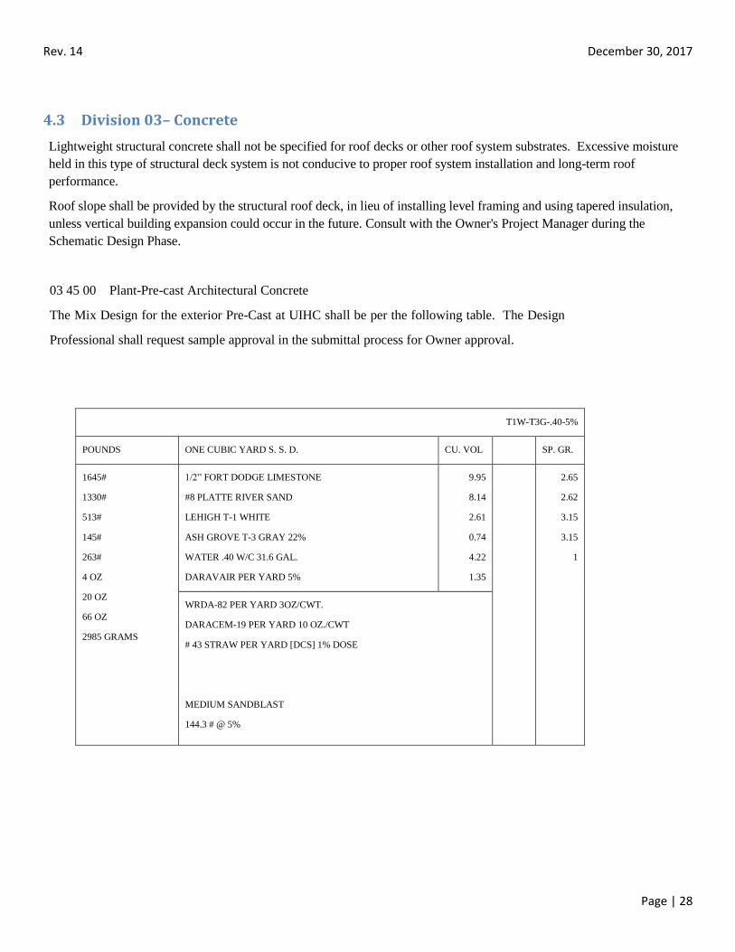
03 45 00 Plant-Pre-cast Architectural Concrete
The Mix Design for the exterior Pre-Cast at UIHC shall be per the following table. The Design
Professional shall request sample approval in the submittal process for Owner approval.
T1W-T3G-.40-5%
POUNDS ONE CUBIC YARD S. S. D. CU. VOL SP. GR.
1645#
1330#
513#
145#
263#
4 OZ
20 OZ
66 OZ
2985 GRAMS
1/2” FORT DODGE LIMESTONE
#8 PLATTE RIVER SAND
LEHIGH T-1 WHITE
ASH GROVE T-3 GRAY 22%
WATER .40 W/C 31.6 GAL.
DARAVAIR PER YARD 5%
9.95
8.14
2.61
0.74
4.22
1.35
2.65
2.62
3.15
3.15
1
WRDA-82 PER YARD 3OZ/CWT.
DARACEM-19 PER YARD 10 OZ./CWT
# 43 STRAW PER YARD [DCS] 1% DOSE
MEDIUM SANDBLAST
144.3 # @ 5%
Rev. 14 December 30, 2017
Page | 29
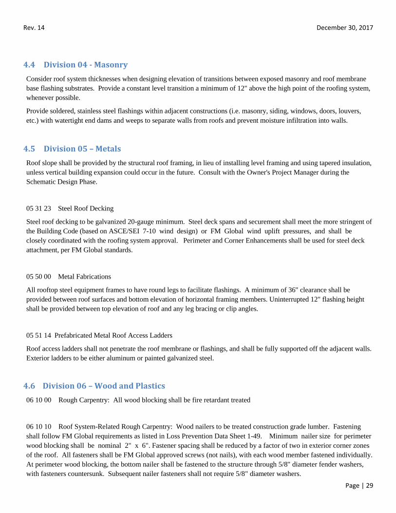
4.4 Division 04 - Masonry
Consider roof system thicknesses when designing elevation of transitions between exposed masonry and roof membrane
base flashing substrates. Provide a constant level transition a minimum of 12" above the high point of the roofing system,
whenever possible.
Provide soldered, stainless steel flashings within adjacent constructions (i.e. masonry, siding, windows, doors, louvers,
etc.) with watertight end dams and weeps to separate walls from roofs and prevent moisture infiltration into walls.
4.5 Division 05 – Metals
Roof slope shall be provided by the structural roof framing, in lieu of installing level framing and using tapered insulation,
unless vertical building expansion could occur in the future. Consult with the Owner's Project Manager during the
Schematic Design Phase.
05 31 23 Steel Roof Decking
Steel roof decking to be galvanized 20-gauge minimum. Steel deck spans and securement shall meet the more stringent of
the Building Code (based on ASCE/SEI 7-10 wind design) or FM Global wind uplift pressures, and shall be
closely coordinated with the roofing system approval. Perimeter and Corner Enhancements shall be used for steel deck
attachment, per FM Global standards.
05 50 00 Metal Fabrications
All rooftop steel equipment frames to have round legs to facilitate flashings. A minimum of 36" clearance shall be
provided between roof surfaces and bottom elevation of horizontal framing members. Uninterrupted 12" flashing height
shall be provided between top elevation of roof and any leg bracing or clip angles.
05 51 14 Prefabricated Metal Roof Access Ladders
Roof access ladders shall not penetrate the roof membrane or flashings, and shall be fully supported off the adjacent walls.
Exterior ladders to be either aluminum or painted galvanized steel.
4.6 Division 06 – Wood and Plastics
06 10 00 Rough Carpentry: All wood blocking shall be fire retardant treated
06 10 10 Roof System-Related Rough Carpentry: Wood nailers to be treated construction grade lumber. Fastening
shall follow FM Global requirements as listed in Loss Prevention Data Sheet 1-49. Minimum nailer size for perimeter
wood blocking shall be nominal 2" x 6". Fastener spacing shall be reduced by a factor of two in exterior corner zones
of the roof. All fasteners shall be FM Global approved screws (not nails), with each wood member fastened individually.
At perimeter wood blocking, the bottom nailer shall be fastened to the structure through 5/8" diameter fender washers,
with fasteners countersunk. Subsequent nailer fasteners shall not require 5/8" diameter washers.
Rev. 14 December 30, 2017
Page | 30
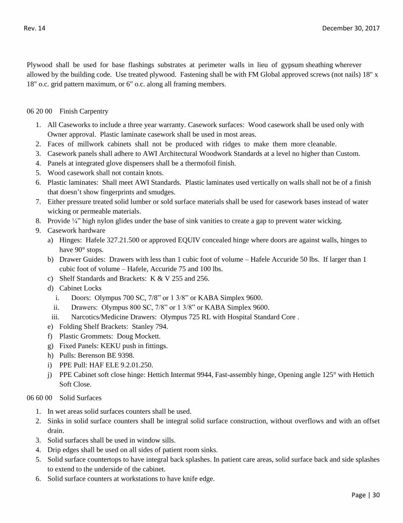
Plywood shall be used for base flashings substrates at perimeter walls in lieu of gypsum sheathing wherever
allowed by the building code. Use treated plywood. Fastening shall be with FM Global approved screws (not nails) 18" x
18" o.c. grid pattern maximum, or 6" o.c. along all framing members.
06 20 00 Finish Carpentry
1. All Caseworks to include a three year warranty. Casework surfaces: Wood casework shall be used only with
Owner approval. Plastic laminate casework shall be used in most areas.
2. Faces of millwork cabinets shall not be produced with ridges to make them more cleanable.
3. Casework panels shall adhere to AWI Architectural Woodwork Standards at a level no higher than Custom.
4. Panels at integrated glove dispensers shall be a thermofoil finish.
5. Wood casework shall not contain knots.
6. Plastic laminates: Shall meet AWI Standards. Plastic laminates used vertically on walls shall not be of a finish
that doesn’t show fingerprints and smudges.
7. Either pressure treated solid lumber or sold surface materials shall be used for casework bases instead of water
wicking or permeable materials.
8. Provide ¼” high nylon glides under the base of sink vanities to create a gap to prevent water wicking.
9. Casework hardware
a) Hinges: Hafele 327.21.500 or approved EQUIV concealed hinge where doors are against walls, hinges to
have 90° stops.
b) Drawer Guides: Drawers with less than 1 cubic foot of volume – Hafele Accuride 50 lbs. If larger than 1
cubic foot of volume – Hafele, Accuride 75 and 100 lbs.
c) Shelf Standards and Brackets: K & V 255 and 256.
d) Cabinet Locks
i. Doors: Olympus 700 SC, 7/8” or 1 3/8” or KABA Simplex 9600.
ii. Drawers: Olympus 800 SC, 7/8” or 1 3/8” or KABA Simplex 9600.
iii. Narcotics/Medicine Drawers: Olympus 725 RL with Hospital Standard Core .
e) Folding Shelf Brackets: Stanley 794.
f) Plastic Grommets: Doug Mockett.
g) Fixed Panels: KEKU push in fittings.
h) Pulls: Berenson BE 9398.
i) PPE Pull: HAF ELE 9.2.01.250.
j) PPE Cabinet soft close hinge: Hettich Intermat 9944, Fast-assembly hinge, Opening angle 125° with Hettich
Soft Close.
06 60 00 Solid Surfaces
1. In wet areas solid surfaces counters shall be used.
2. Sinks in solid surface counters shall be integral solid surface construction, without overflows and with an offset
drain.
3. Solid surfaces shall be used in window sills.
4. Drip edges shall be used on all sides of patient room sinks.
5. Solid surface countertops to have integral back splashes. In patient care areas, solid surface back and side splashes
to extend to the underside of the cabinet.
6. Solid surface counters at workstations to have knife edge.
Rev. 14 December 30, 2017
Page | 31
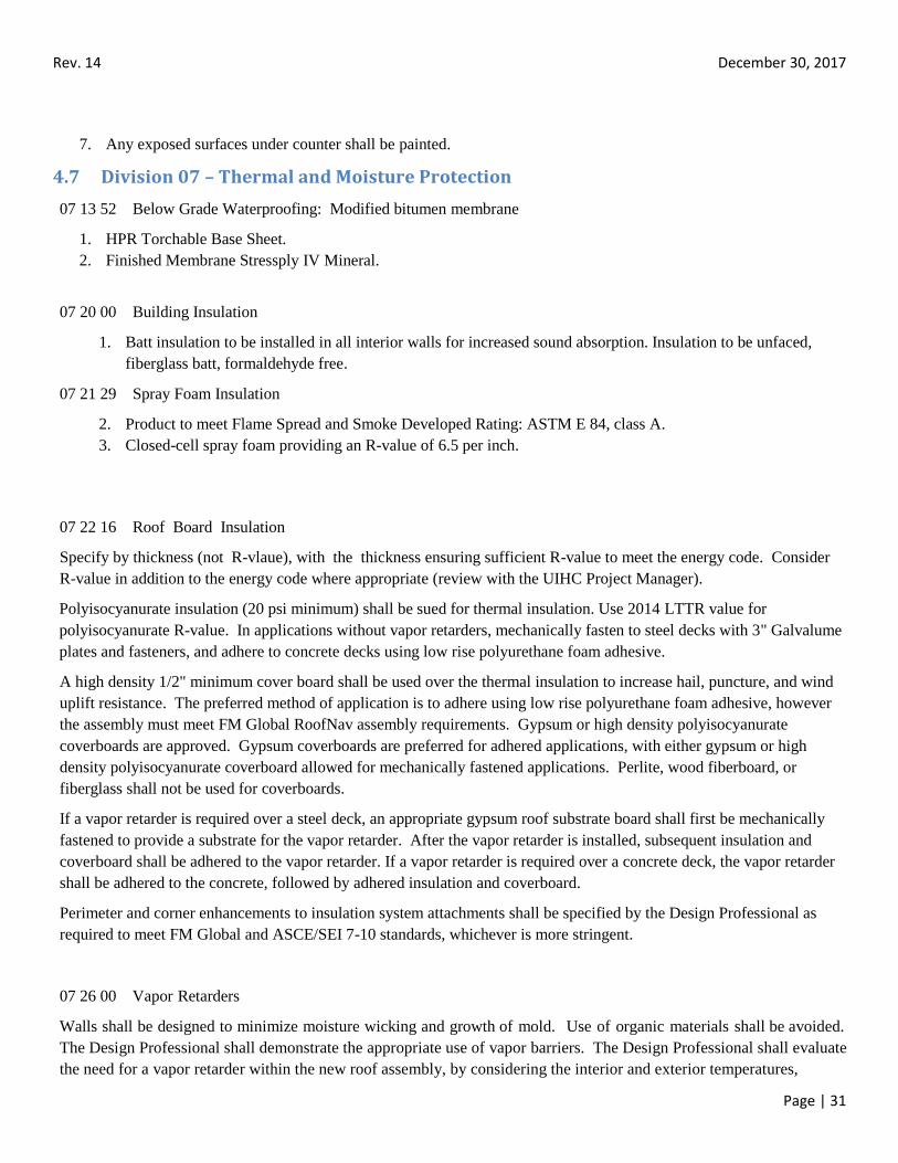
7. Any exposed surfaces under counter shall be painted.
4.7 Division 07 – Thermal and Moisture Protection
07 13 52 Below Grade Waterproofing: Modified bitumen membrane
1. HPR Torchable Base Sheet.
2. Finished Membrane Stressply IV Mineral.
07 20 00 Building Insulation
1. Batt insulation to be installed in all interior walls for increased sound absorption. Insulation to be unfaced,
fiberglass batt, formaldehyde free.
07 21 29 Spray Foam Insulation
2. Product to meet Flame Spread and Smoke Developed Rating: ASTM E 84, class A.
3. Closed-cell spray foam providing an R-value of 6.5 per inch.
07 22 16 Roof Board Insulation
Specify by thickness (not R-vlaue), with the thickness ensuring sufficient R-value to meet the energy code. Consider
R-value in addition to the energy code where appropriate (review with the UIHC Project Manager).
Polyisocyanurate insulation (20 psi minimum) shall be sued for thermal insulation. Use 2014 LTTR value for
polyisocyanurate R-value. In applications without vapor retarders, mechanically fasten to steel decks with 3" Galvalume
plates and fasteners, and adhere to concrete decks using low rise polyurethane foam adhesive.
A high density 1/2" minimum cover board shall be used over the thermal insulation to increase hail, puncture, and wind
uplift resistance. The preferred method of application is to adhere using low rise polyurethane foam adhesive, however
the assembly must meet FM Global RoofNav assembly requirements. Gypsum or high density polyisocyanurate
coverboards are approved. Gypsum coverboards are preferred for adhered applications, with either gypsum or high
density polyisocyanurate coverboard allowed for mechanically fastened applications. Perlite, wood fiberboard, or
fiberglass shall not be used for coverboards.
If a vapor retarder is required over a steel deck, an appropriate gypsum roof substrate board shall first be mechanically
fastened to provide a substrate for the vapor retarder. After the vapor retarder is installed, subsequent insulation and
coverboard shall be adhered to the vapor retarder. If a vapor retarder is required over a concrete deck, the vapor retarder
shall be adhered to the concrete, followed by adhered insulation and coverboard.
Perimeter and corner enhancements to insulation system attachments shall be specified by the Design Professional as
required to meet FM Global and ASCE/SEI 7-10 standards, whichever is more stringent.
07 26 00 Vapor Retarders
Walls shall be designed to minimize moisture wicking and growth of mold. Use of organic materials shall be avoided.
The Design Professional shall demonstrate the appropriate use of vapor barriers. The Design Professional shall evaluate
the need for a vapor retarder within the new roof assembly, by considering the interior and exterior temperatures,

Rev. 14 December 30, 2017
Page | 32
anticipated interior relative humidity, interior occupancies and processes, and location of dew point within the roof
assembly during anticipated January temperatures. Where applicable, a vapor retarder with continuous functional
flashing systems, shall be designed on the warm side of the roof assembly, with sufficient insulation specified to
maintain the vapor retarder above the dew point temperature and prevent condensation. Vapor retarder systems shall not
be penetrated by roof system fasteners.
07 27 00 Air Barriers
Air barriers shall be used in roof systems, and shall be continuous with adjacent wall system air barriers, where/as
required to meet the building code.
07 50 00 - Membrane Roofing
Membrane selection requires evaluation by the Design Professional UIHC Design Team, Engineering Services, and
review and approval by the UIHC Project Manager.
In addition, the roof system must meet the criteria listed in Part I. General Requirements. It shall also be the Design
Professional's responsibility to follow the FM Global Roof Design Process described in Paragraph 2.1.5 of this standard.
The Design Professional shall not assume that just because a roof assembly has an FM Global RoofNav Assembly
Number, that the roof assembly is appropriate for the project, meets the membrane Manufacturer's requirements, or is
eligible for UIHC's required warranty type. The Design Professional shall verify these items with the Manufacturer's
Technical Representatives and design the roof system to meet all applicable standards.
Peel stops shall be considered at the perimeters of adhered single-ply membrane systems. Peel stops shall be carefully
designed if a vapor retarder is required, to prevent breaches where fasteners penetrate the roof system.
Walkways shall be provided at traffic paths and around rooftop equipment requiring maintenance. Follow the shortest
distance between points - right angles discourage use. Consider window washing operations, where required, when
designing walkway layouts. Consider additional walkways for roof systems that have a low slip-resistance rating.
Base flashing terminations shall be detailed with termination bars and positive seals, independent of sheet metal flashings.
Locate terminations below through-wall flashings and weep systems where present. Install secondary metal
counterflashings over terminations.
Solvent-based adhesives shall be specified, to allow widest application temperature windows and maximum flexibility in
construction scheduling during cold weather.
Penetration flashing details shall be accomplished without the use of pitch pans. Pipe chases with sheet metal covers
shall be used at utility penetrations associated with mechanical, electrical, and communication systems.
Wood blocking shall not be used to support mechanical, electrical, or communication piping, conduits, raceways, cable
trays, lines, etc. See Division 23 for required types and manufacturers of supports. Set supports over roof membrane
manufacturer's recommended walkway material.
Approved Roof Membrane Manufacturers are as listed below, and substitutions shall not be specified unless first
approved in writing by the UIHC Project Manager.
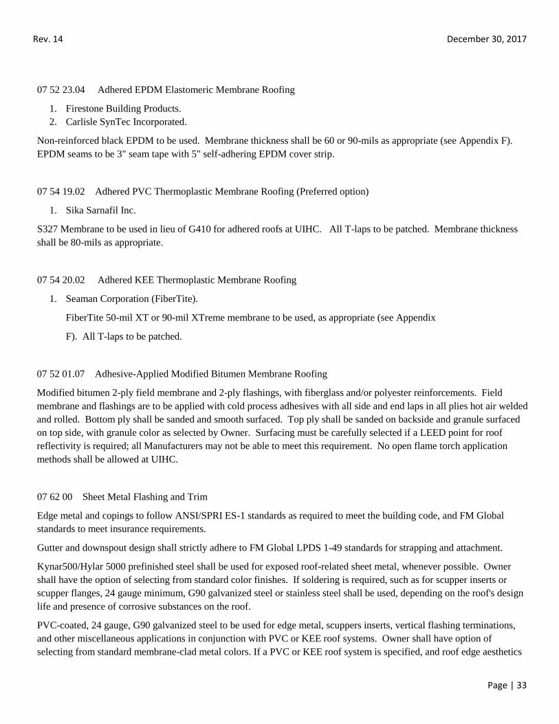
Rev. 14 December 30, 2017
Page | 33
07 52 23.04 Adhered EPDM Elastomeric Membrane Roofing
1. Firestone Building Products.
2. Carlisle SynTec Incorporated.
Non-reinforced black EPDM to be used. Membrane thickness shall be 60 or 90-mils as appropriate (see Appendix F).
EPDM seams to be 3" seam tape with 5" self-adhering EPDM cover strip.
07 54 19.02 Adhered PVC Thermoplastic Membrane Roofing (Preferred option)
1. Sika Sarnafil Inc.
S327 Membrane to be used in lieu of G410 for adhered roofs at UIHC. All T-laps to be patched. Membrane thickness
shall be 80-mils as appropriate.
07 54 20.02 Adhered KEE Thermoplastic Membrane Roofing
1. Seaman Corporation (FiberTite).
FiberTite 50-mil XT or 90-mil XTreme membrane to be used, as appropriate (see Appendix
F). All T-laps to be patched.
07 52 01.07 Adhesive-Applied Modified Bitumen Membrane Roofing
Modified bitumen 2-ply field membrane and 2-ply flashings, with fiberglass and/or polyester reinforcements. Field
membrane and flashings are to be applied with cold process adhesives with all side and end laps in all plies hot air welded
and rolled. Bottom ply shall be sanded and smooth surfaced. Top ply shall be sanded on backside and granule surfaced
on top side, with granule color as selected by Owner. Surfacing must be carefully selected if a LEED point for roof
reflectivity is required; all Manufacturers may not be able to meet this requirement. No open flame torch application
methods shall be allowed at UIHC.
07 62 00 Sheet Metal Flashing and Trim
Edge metal and copings to follow ANSI/SPRI ES-1 standards as required to meet the building code, and FM Global
standards to meet insurance requirements.
Gutter and downspout design shall strictly adhere to FM Global LPDS 1-49 standards for strapping and attachment.
Kynar500/Hylar 5000 prefinished steel shall be used for exposed roof-related sheet metal, whenever possible. Owner
shall have the option of selecting from standard color finishes. If soldering is required, such as for scupper inserts or
scupper flanges, 24 gauge minimum, G90 galvanized steel or stainless steel shall be used, depending on the roof's design
life and presence of corrosive substances on the roof.
PVC-coated, 24 gauge, G90 galvanized steel to be used for edge metal, scuppers inserts, vertical flashing terminations,
and other miscellaneous applications in conjunction with PVC or KEE roof systems. Owner shall have option of
selecting from standard membrane-clad metal colors. If a PVC or KEE roof system is specified, and roof edge aesthetics
Rev. 14 December 30, 2017
Page | 34
are critical, a membrane manufacturer-supplied prefabricated fascia system with Kynar prefinished cover plate and
extruded aluminum anchor bar shall be used.
All fasteners shall be FM Global approved, stainless steel with EPDM washers. Nailing of metal flanges shall be hot dip
galvanized or stainless steel, ring shank nails.
All parapet walls, expansion/control joint curbs, and curb-to-ductwork flashings shall be waterproofed with seamed
single-ply membrane, prior to installing sheet metal coping caps or covers.
Include sealants and required accessories for sealing sheet metal flashing in this section. Silyl- Terminated Polyether
sealant and manufacturer-recommended sealant primer shall be used for all sheet metal joints. Sonolastic 150 VLM and
Primer 733 by BASF Building Systems shall be the basis for design.
Minimum gauge thicknesses for roof-related sheet metal flashing and trim:
1. Edge Metal: 24 gauge.
2. Counterflashings: 24 gauge.
3. Coping Caps: 22 gauge.
4. Expansion/Control Joint Covers: 22 gauge.
5. Suppers: 24 gauge.
6. Conductor Heads: 22 gauge.
7. Gutters: 22 gauge.
8. Downspouts: 22 gauge.
07 72 33 Roof Hatches
Roof access hatches shall be as manufactured by The Bilco Company, with mill finish aluminum construction. Prime
painted steel construction shall only be used where painting of the roof hatch will occur for aesthetic reasons.
07 81 00 Fireproofing
Fire proofing shall be cementitious.
07 84 00 Firestopping:
1. SCOPE/ APPLICATION
Project Architect or Design Professional shall specify firestopping requirements on drawings and project
specifications which shall:
a) Provide installed firestop products that limit the spread of fire, heat, smoke, and gasses through otherwise
unprotected openings in rated assemblies, including walls, partitions, floors, roof/ceilings, and similar
locations, restoring the integrity of the fire rated construction to its original fire rating.
b) Provide fire resistive systems listed for construction gaps per the specific combination of fire-rated
construction type, configuration, gap dimensions, and fire rating.
c) Provide systems manufactured by 3M,HILTI, or approved equivalent that are listed by Underwriters
i. Laboratories Inc. (UL), in "Fire Resistance Directory”.
ii. Must be red in color
Rev. 14 December 30, 2017
Page | 35
2. All Specifications Shall Meet the Following Requirements:
a. Install in strict accordance with manufacturer's detailed installation instructions and procedures.
Penetrations shall be sealed from both sides of the penetration, when accessible.
b. Use only products specifically listed for use in listed systems.
c. Firestopping materials must meet and be acceptable for use by all building codes and NFPA codes.
3. Other Requirements:
a) Where firestop systems not listed by any listing agency are required due to project conditions, submit a
substitution proposal with evidence specified, to be reviewed for owner approval.
b) Do not conceal firestopping installations until the Owner’s inspection agency or authorities having
jurisdiction have examined each installation. Owner, Design Professional and Installing Contractor will
conduct and document a comprehensive inspection of all installed firestopping.
c) Installer Qualifications: Firm must be qualified by having experienced staff who are properly trained to
install the specified products, by completing the manufacturer's certified product installation training.
Contractor must provide certificate of qualification.
d) At project closeout, provide to Owner or Owners Representative an executed copy of the manufacturer's
standard limited warranty against manufacturing defect, outlining its terms, conditions, and exclusions from
coverage.
e) Provide copy of all engineering judgments to owner.
f) Every location must include a label identifying who installed it, when and the system that was used.
4.8 Division 08 – Openings
NOTES:
Hardware substitutions are not permissible unless approved by chief architect
Design Professional will provide a door schedule electronically in an Excel spreadsheet
Door security designations will follow the Design Standard designations found in this Standard, section 4.20
Consider roof system thicknesses when designing flashing substrates and setting elevations of doors, windows, and louvers
adjacent to roofs
Provide 12" minimum flashing height above insulation at all base flashing substrates, including below doors, windows, and
louvers.
Provide soldered, stainless steel flashings within adjacent constructions (i.e. masonry, siding, windows, doors, louvers, etc.) with
watertight end dams and weeps to separate walls and wall penetrations from roofs and prevent moisture infiltration into walls.
All doors in Patient and Public Access areas shall be 42” wide, minimum.
08 12 00 Steel Door Frames
1. 14ga. on exterior doors and interior doors over 4’-0” wide.
2. Doors greater than 3’ wide or over 84” high require 4 hinges.
3. 16ga. on all other interior doors.
4. Corner joints shall be mitered, interlocked, welded and ground smooth.
5. Frames shall be template reinforced for hardware 7ga. on hinges, 12 ga. everywhere else.
6. Acceptable manufacturers: Ceco, Curries, Steelcraft, or Owner approved equal.
7. Use 4” Hospital Stops on inpatient areas, treatment, procedure and any other areas where integral cove bases are
required.
8. All frames to be grouted full.
Rev. 14 December 30, 2017
Page | 36
08 13 00 Hollow Metal Flush Doors
1. All doors fire rated at 90 minutes or higher shall be hollow metal and be UL fire rated and meet NFPA 80
standard.
2. Doors greater than 3’ wide or over 84” high require 4 hinges.
3. Painted hollow metal doors shall be used in cross-corridor and double egress situations.
4. Exterior: SDI-100 Grade III, 16ga. galvanized faces, seamless edges, R-10, polyurethane core.
5. Interior: SDI-100 Grade II, 18ga. faces, seamless edges with 20ga. stiffeners and sound insulation core.
6. Doors shall be template reinforced for hardware 7ga. on hinges, 12ga. everywhere else.
7. Acceptable manufacturers: Ceco, Curries, Steelcraft, or Owner approved equal.
8. Faux wood hollow metal doors are not to be used.
08 14 00 Flush Wood Doors
1. All doors not rated or fire rated to less than 90 minutes shall be flush wood door and be UL fire rated and meet
NFPA 80 standard.
2. Doors greater than 3’ wide or over 84” high require 4 hinges.
3. In high cart traffic areas, doors shall have stainless steel kickplates.
4. Doors shall be solid core particle board, premium grade, plain sliced, red oak (or approved finish materal), book-
matched, 5 ply, AWI 1300. Optional use of eiDoor Vinyl Clad Interior doors by Eggers, VT Industries, Algoma,
or approved MFR is permissible and approved by owner.
5. Finished doors shall not contain knots.
6. Lead lined doors shall be seven ply, solid particle core with hardwood cross bands and lead glued to the core.
Lead lined door size and lead thickness is dependent on the level of radiation protection required. Lead lined
frames and doors shall be installed according to manufacturer’s specifications.
7. Doors shall be premachined for hardware and prefitted to net size.
8. Acceptable manufacturers: Graham, Marshfield, Algoma, Eggers, VT Industries, or Owner approved equal.
9. Mineral core doors are not accepted.
08 31 00 Fire Rated Access Doors
16ga. frame with 20ga. galvanized bonderized steel panels, UL fire rated, meet NFPA 80 standard and must be self-
closing and positive latching. Frame to be trimless, with flush door.
– Cesco, JL Industries, Milcor, or Owner approved equal.
08 33 23 Rolling Fire Doors
22ga. SS or galvanized steel, interlocking slats, prime painted with automatic closing activated by smoke detection
system, UL fire rated and must meet NFPA 80 and local fire codes. – Cookson FD-5 or Owner approved equal. Tube
motors are preferred.
08 51 13 Aluminum Windows
Rev. 14 December 30, 2017
Page | 37
1. Interior
a) Interior aluminum windows shall match existing.
b) Acceptable manufacturers: Wausau, EFCO, Moduline or Owner approved equal.
c) Interior integral blinds shall be Unicel or Hospital approved equivalent.
2. Exterior
a) No windows shall use integral blinds.
b) No pivot-type windows shall be used.
c) Extruded aluminum, prime billet 6063 alloy T5 temper.
d) Anodic finish shall be Architectural Class I, electrolytically deposited minimum thickness 0.7 mil.
e) Color shall match existing; refer to section 1.7.
f) Windows, factory glazing, thermal barrier and related materials shall have a 10 year guarantee.
g) Thermal break shall be Insulbar, nylon impregnated fiberglass. Polyurethane thermal breaks are prohibited.
h) Acceptable manufacturers: Wausau 4250iV Insulbar, EFCO, Visuline Series or Owner approved equal.
i) All new exterior aluminum windows shall pass the following field tests (testing agency shall be procured
by the Owner) in the presence of UIHC Quality Assurance personnel, UIHC Project Manager, General
Contractor, and window manufacturer representative.
i. ASTM E 783-02, Field Measurement of Air Leakage Through Installed Exterior Windows and Doors.
ii. ASTM E 1105-00, Field Determination of Water Penetration of Installed Exterior Windows,
Skylights, Doors, and Curtain Walls, by Uniform of Cyclic Static Air Pressure Difference.
iii. AAMA 501.2-03, Quality Assurance and Diagnostic Water Leakage Field
Check of Installed Storefronts, Curtain Walls, and Sloped Glazing.
08 51 23 Vision Panels
1. 18ga. cold rolled steel, mitered, welded corners with countersunk mounting holes.
2. Anemostat Door Products BFL 123 or Owner approved equal.
08 71 00 Door Hardware
1. Finish: United States Standard US 26D satin chrome for interior doors, SS for exterior doors.
2. Hinges: Full mortised, square cornered, 5 knuckled, ball bearing, template, polished and plated- Hager,
Mckinney, Stanley.
3. Pivots: Heavy Duty Rixon.
4. Swing Clear Hinges: McKinney.
5. Locks, latches and deadbolts: Sargent 8200 mortise, LW1-L, L escutcheon, L lever, curved lip strike, 7 pin
cylinder SFIC.
6. All doors shall be positive latching; roller latches are prohibited.
7. Strikes: SS Dustproof with curved lip.
8. Edge guard: marker EG308 with “adjust-a-screw.”
9. SS Piano Hinges: Assa Abloy marker HG325 with “adjust-a-screw.”
10. Panic Devices: Von Duprin.
NOTE: All panic devices used on fire rated openings must be UL fire rated.
a) Single Doors: Von Duprin series 99L 9975 Mortise x 996 trim with standard O6 lever or 9475.
Rev. 14 December 30, 2017
Page | 38
b) Double Doors: Both leaves 9447 (Impact) concealed vertical rod only.
c) High Traffic Public areas, such as main public corridors, must be metal doors only: Von Duprin 94 series.
11. Coordinator and Carry Bar for double doors: Trimco 3092 series; use open back strike when possible. Can
eliminate by using both concealed vertical rod.
12. Door Closers: LCN Super Smoothee Series 4041XP, Aluminum.
13. Life Safety Closures:
a) Doors with swings less than 105 - LCN Sentronic Series 4040 SE, 120v, Aluminum or LCN Super
Smoothee series 4041XP aluminum with wall mounted magnetic door hold open LCN 7800 series 120V. Wall
mounted magnet is preferred.
b) Doors with swings greater than 105LCN Sentronic Series 4410 ME push-side, 4310 ME on pull-side,
120v, Aluminum. Wall mounted magnet is preferred.
14. Handicapped, barrier-free door controls – Horton 4100 Series.
15. Keying: Final shall be Medeco X4, which is owner supplied.
16. Magnetic Holders: LCN 7800 Series 120v flush mount. Reinforced backing is required behind Holder.
17. In high traffic areas door edge guards shall be used.
18. Overhead stops: Surface mounted only: Glynn Johnson 90 series; Concealed stops shall not be used.
19. Automatic Flush Bolt: Glynn Johnson. Prefer constant latch (self latching).
20. Automatic Door Bottoms: Zero 360, Reese 521.
21. Smoke Seal Assemblies: Reese 897B, National Guard.
22. Wall Bumper: Ives 401, 402, 403. Reinforced backing is required behind Bumper.
23. Thresholds: Zero 564B.
24. Astragals: Zero 183 DUR. Astragals shall be avoided, if at all possible.
25. Door Silencers: Ives.
26. Door Stop: Ives.
27. Extension Flush Bolt: Ives358.
28. Self Latching Flush Bolts: Ives 356, 357.
29. Electric Strikes: HES 1006 with Smart Pak and typically KM faceplate option. Confirm faceplate option. HES
9500 surface with Smart Pak.
30. Power Supply for electric strike: Locknetics 505 or 510 – strikes; Von Duprin PS 914 – for EL99 or CX99.
31. Power transfer: McKinney EL-EPT-SC.
32. Electric Lockset: Sargent Mortise Lockset 8271 – Trim and Finish to match typical hardware (24VDC with RX
switch).
33. Electric Interlock for failsafe operation: Kam-Lock 3020.
34. Combination Locks: Kaba E5000 series.
35. Push/Pull Hospital Latch for Patient Rooms: Sargent 7800 series.
36. Card reader Locksets for patient guest rooms (such as Rossi Guest House): ILCO series 700 (Hotel-Motel).
37. On-call room doors: Sargent 82281 Lock Body with LW1L trim reader by access control
Rev. 14 December 30, 2017
Page | 39
08 74 00 Access Control Hardware
1. Single Door: Von Duprin, delayed egres Chexit Controlled exit device, CX9975.
2. Double Doors: Leaf #1 - Von Duprin, delayed egres Chexit Controlled exit device, CX9975; Leaf #2 - Von
Duprin CX9947 concealed vertical rod.
3. Hes Innovations, HES 1006 Series Heavy duty electric strike and Smart Pak with appropriate faceplate
option Power supply provided by Access Control Provider.
4. Von Duprin, DC 2004 Desk Console (if required).
5. CCTV Camera, Bosche or Sanyo 24 v, color camera (IP DOE style).
6. Door position switch, magnet top jamb type: George Risk Industries (GRI) models
8080-TWG-B, 7623-TWG-G or 200-26, depending on application.
7. Power transfer-McKinney EL-EPT-SC.
8. Von Duprin power supply PS-914.
08 80 00 Glass and Glazing
1. Clear tempered ¼” thick float glass.
2. Bronze tint tempered ¼” thick float glass for exterior windows.
3. Insulating glass 1” thick composed of ¼” reflective, heat strengthened bronze tint float glass, ½” air space and
interior lite of ¼” clear float glass.
4. 5/8” clear laminated heat strengthened float glass.
5. Acceptable manufacturers: PPG, Ford Glass, Viracon; Wireglass manufacturers: Central
Glass, Ashai Glass, HJ Martin & Son.
6. Fire rated glass: TGP “Firelite.”
4.9 Division 09 – Finishes
NOTE: Substitute low or zero volatile organic compound (VOC) paints, stains, adhesives, sealants and other construction materials, where
practical.
09 22 16 Non-Load Bearing Partition Framing
1. Steel stud partitions shall be 20 gauge minimum for interior partitions. Taller walls may require heavier gauge
studs.
09 29 00 Gypsum Wallboard
1. To avoid moisture wicking, undercut outer layer of gypsum wallboard by 1/4” at base and caulk with moisture
resistant caulk that meets fire rating for wall. All gypsum wall board to go to deck or structure above.
2. In wet areas and areas near sinks and ice machines non-moisture wicking wallboard shall be specified; USG
FIBEROCK Brand Aqua-Tough Interior Panels or Owner approved equal.
3. O.R.’s and high abuse areas to receive impact resistant gypsum board.
Rev. 14 December 30, 2017
Page | 40
09 50 00 Acoustical Ceilings
1. Standard tile is 24” x 24” Armstrong Ultima Health Zone, 9/16” Tegular Edge (1936) with 9/16” Suprafine grid or
approved equivalent.
09 65 00 Resilient Flooring
1. Resilient flooring to be Nora or approved equal. Nora Plan Envirocare in patient care areas. Inpatient rooms,
procedure areas, cleanrooms and other places where required to have a 6” integral cove terminated with a cold
weld against at the wall. Provide (1) #1 Nora Pad for every 10,000 square feet of Envirocare installed.
Nora Norament Grano tiles to be used in main public corridors.
2. Any patterns must be water jet cut.
3. All seams to be hot welded.
4. Acrylic adhesive to be used as a standard. For OR’s and areas with heavy rolling loads, Dryfix is recommended.
09 68 16 Rolled Carpet
1. Carpet to be 100% solution dyed nylon. 6’ wide Tandus Powerbond or approved equivalent.
09 72 50 Epoxy Quartz Flooring
1. Flooring and Base: Aggregate of coated quartz, embedded in clear epoxy and applied to a total thickness of 1/16"
to 1/8", as recommended by the manufacturer. Apply two (2) coats of manufacturer’s sealer topcoat to reduce
texture. Verify texture with users after initial topcoat application.
2. Clear floor sealers are not allowed.
09 90 00 Painting and Coating
1. Metal Doors and Frames
a) 1 Coat S-W Pro Industrial Pro-Cryl, B66-310 Series.
i. Alternate: Interior and Exterior; Ferrous and Non Ferrous Metals (very smooth and/or Kynar like
surfaces).
ii. Bonding Primer: 1 Coat S-W DTM Bonding Primer, B66A50.
b) Finish: 1-2 Coats S-W Pro Industrial Acrylic, B66-600 Series available in Gloss, Semi-Gloss, and Egg-Shell.
c) Doors and frames to be painted the same color on both sides.
2. Wood Doors
a) New wood doors shall be prepped and stained or painted offsite.
b) When painting over existing wood lacquered doors, doors shall be removed and prepared offsite. The
following shall also be specified:
iii. Prior to painting, doors shall be power sanded smooth to remove the existing stain.
iv. Primer shall be one coat of XIM Advanced Technology UMA brand Bonder.
v. Finish: 1-2 Coats S-W Pro Industrial Acrylic, B66-600 Series available in Gloss, Semi-Gloss, and
Egg-Shell.
3. Fire and Smoke Wall Markings
Rev. 14 December 30, 2017
Page | 41
a) Provide permanent marking of all fire (1 hour, 2 hour, etc.) and smoke rated partitions.
b) Marking shall be an 8 inch diameter fluorescent orange painted circle applied 6-12 inches above the finished
ceiling with a 4 inch black numeral or letters stenciled over the orange circle
c) The markings shall be on both sides of all rated partitions and in every adjacent room.
d) The spacing shall not be over 8 feet on center.
4. Walls
a) Standard wall paint to be Sherwin Williams Pro Mar 200 Egg Shell or approved equal.
09 96 56 Epoxy Paint
1. Epoxy paint shall be specified for operating and procedure rooms where surfaces need to be scrubbable.
2. Sherwin Williams “Pro Industrial – Zero VOC Waterborn Catalyzed Epoxy - #B73-360 Series Eg-Shel.”
3. Paint other than white at hand sanitizer locations shall be Sherwin Williams Pre Catalyzed Water Based Epoxy
4.10 Division 10 – Specialties
10 14 00 Signage
1. The preferred plaque for LEED accredited facilities is the “Polished Water Jet Cut Aluminum - Clear Coated”
plaque.
2. All new signage to be ASI Venus Series or Hospital Architect Approved equivalent.
10 21 13 Toilet Compartments
1. Toilet compartments shall be stainless steel or solid surface and ceiling hung.
2. Hardware for toilet compartments shall have a safety release latch that allows the door to be opened from the
outside in the case of an emergency
10 21 23 Cubicles
10 21 23.13 Cubicle Curtains: Comply with NFPA 13. Mesh extensions of 18” required on top of
curtain unless coordinated with sprinkler installation. Get Owner approval for chosen design.
10 21 23.16 Cubicle Track and IV Track: Surface mounted track and carrier assemblies: “On the Right Track,”
General Cubicle or Owner approved equal.
10 22 00 Fire Rated Folding Partition
1. Horizontal Sliding partition, 1-hour fire rated, STC 50. Won Door Fireguard Model 20.
2. Closing systems shall be automatic composed of a microprocessor control box, key switch module, motor drive
unit and leading edge obstruction detector
3. The microprocessor control box and key switch module shall be accessible whether the door is open or closed.
Rev. 14 December 30, 2017
Page | 42
10 22 26 Operable Partitions
1. Manual or electric, accordion, STC 39, Modernfold Soundmaster 8 or Skyfold (Preferred)
10 26 00 Corner Guards
1. Corner guards to be Koroseal GS25, 2 ½” Stainless Steel. The corner guards should sit at top of resilient base.
The resilient base is not to run across the corner guard. The top of the corner guard should be 1/4" below
suspended grid ceiling.
10 26 33 Kickplates: Screwed on, stainless steel, US 26D.
10 28 00 Toilet and Bath Accessories
1. Manufacturers: Bobrick, Bradley or American Specialties. Units listed below are based on Bobrick. Other
manufacturer’s models must be equal to the listed Bobrick models.
a) Soap dispensers – Renown FX (Provided by EVS)
b) Grab bars – B6806 Series; 1 ½” diameter which conform with ADA regulations.
c) Towel bar – B674.
d) Mirror – B290 Series.
e) Towel hook – B6717.
f) Robe hooks – B671.
g) Mop holders – B233.
h) Stainless steel shelf – B295.
i. Foot operated susrgical soap dispenser – B119.
2. Paper Towel Dispensers
a) High use public areas
i. Silhouette Wave’n Dry Electronic Touch-Free, Model #80000, color: Black
ii. When space does not allow for the options above, with Owner’s approval, the following dispensers
can be used:
Full size stainless steel multi-fold paper towel dispenser – Bobrick B-2620
Keyless Surface Mounted
b) Public, Staff Restrooms, Exam Rooms & Patient Rooms: Utilize the stainless steel multi-fold towel dispensers
of the dimensions shown below.
Full size stainless steel multi-fold paper towel dispenser – Bobrick B-2620
Keyless surface Mounted
Half size stainless steel multi-fold paper towel dispenser- Bobrick B-2621
Keyless Surface Mounted
Rev. 14 December 30, 2017
Page | 43
3. Bath Tissue Dispensers
a) Semi recessed, two roll stainless steel, ASI 74022 or equivalent.
4. Toilet Seat Cover Dispenser: Silhouette Toilet Seat Cover Dispenser, Model #19510, color: Black
Translucent – 16 1/8”w x 11 7/8”h x 3 1/8”d, 1lb.
5. Sanitary Napkin Receptacle – Bobrick B-270. Used only in multi stall restrooms.
6. Infant Changing Station: Koala Bear Care baby 10829, horizontal design or Owner approved equal.
7. Shower seat folding: Hewi 950.51.21090.
8. Integral wall hung trashcans shall not be used.
9. Include a bedpan washing system in all inpatient water closets.
10 44 00 Fire Extinguisher Cabinets
1. Fire Extinguisher Cabinets to be Larsen 2720-R, Clear Tempered Glass, Vertical Duo Style, vertical Red Lettering ,
Stainless Steel, with Flat Fully Recessed trim. Larsen or approved equiv.
2. Where fire extinguisher cabinets are installed, furnish with: one carbon dioxide fire extinguisher (five pounds) and a
2.5 gallon water extinguisher.
3. All extinguishers shall be manufactured by Amerex, Ansul, or Owner approved equivalent. Design basis shall be
Amerex 320 for the carbon dioxide fire extinguisher.
10 51 00 Lockers
4. Two person duplex lockers, 15” wide, mortise and tenon door frames, finished end panels, sloping tops, “Z” type
closed bases, friction catch latch for use with padlocks. Soundproof, “Quiet” lockers. No combination locks.
5. Manufacturers: Penco, Lyon, Republic Steel.
10 90 00 Miscellaneous Specialties
1. Alcohol-Based Gel Dispenser Installation:
a) Gel dispensers shall not be installed in corridors that are less than 6 feet wide.
b) At least 4 feet of space must be kept between dispensers.
c) Dispensers shall not be hung within 6 inches of or directly above adjacent ignition sources (including outlets
and switches), measuring out from the center of the dispenser.
d) The dispensers shall be hung 42-48 inches above the finished floor.
2. Television Brackets: Model to fit TV specified by HCIS.
3. FSR boxes are to be used behind public TV’s. Specific models and locations to be coordinated with HCIS.
4. Custodial Closet Specialties
a. Utility mop sink, not more than 10” deep.
a) Shelving: Wooden set on metal standards and brackets.
i. Dimensions: 18”d x 0.75”t; cut to fit the designated area.
ii. Coordinate with Environmental Services during design to determine the number of shelves required.
Typically, it will be 2-4 shelves.
b) Grip-All mop handle holders, minimum 2, installed 78” above finished floor.
c) Three coat hooks. Coordinate locations with Environmental Services.
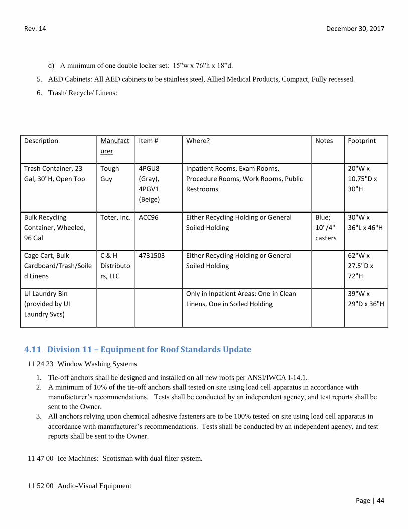
Rev. 14 December 30, 2017
Page | 44
d) A minimum of one double locker set: 15”w x 76”h x 18”d.
5. AED Cabinets: All AED cabinets to be stainless steel, Allied Medical Products, Compact, Fully recessed.
6. Trash/ Recycle/ Linens:
Description Manufact
urer
Item # Where? Notes Footprint
Trash Container, 23
Gal, 30"H, Open Top
Tough
Guy
4PGU8
(Gray),
4PGV1
(Beige)
Inpatient Rooms, Exam Rooms,
Procedure Rooms, Work Rooms, Public
Restrooms
20"W x
10.75"D x
30"H
Bulk Recycling
Container, Wheeled,
96 Gal
Toter, Inc. ACC96 Either Recycling Holding or General
Soiled Holding
Blue;
10"/4"
casters
30"W x
36"L x 46"H
Cage Cart, Bulk
Cardboard/Trash/Soile
d Linens
C & H
Distributo
rs, LLC
4731503 Either Recycling Holding or General
Soiled Holding
62"W x
27.5"D x
72"H
UI Laundry Bin
(provided by UI
Laundry Svcs)
Only in Inpatient Areas: One in Clean
Linens, One in Soiled Holding
39"W x
29"D x 36"H
4.11 Division 11 – Equipment for Roof Standards Update
11 24 23 Window Washing Systems
1. Tie-off anchors shall be designed and installed on all new roofs per ANSI/IWCA I-14.1.
2. A minimum of 10% of the tie-off anchors shall tested on site using load cell apparatus in accordance with
manufacturer’s recommendations. Tests shall be conducted by an independent agency, and test reports shall be
sent to the Owner.
3. All anchors relying upon chemical adhesive fasteners are to be 100% tested on site using load cell apparatus in
accordance with manufacturer’s recommendations. Tests shall be conducted by an independent agency, and test
reports shall be sent to the Owner.
11 47 00 Ice Machines: Scottsman with dual filter system.
11 52 00 Audio-Visual Equipment
Rev. 14 December 30, 2017
Page | 45
1. Projectors: Contact Owner to discuss projectors and other related AV equipment.
2. The designer shall utilize equipment racks for AV equipment.
11 52 13 Projection Screens: Manual screens shall be specified. Owner approval required for motorized.
1. Manual with controlled screen return (CSR): Da-Lite Advantage or Draper.
2. Tensioned concealed (recessed) ceiling mounted, motorized:
a) Da-Lite Tensioned Advantage Electrol or Tensioned Avantage Deluxe Electrol.
b) Draper Tensioned Access/Series V.
c) Stuart – for high resolution and specialized viewing applications.
11 70 00 Healthcare Equipment
1. Blanket Warming Cabinets: Coordinate selection with Owner.
4.12 Division 12 – Furnishings
12 24 13 Roller Shades
1. Shades to be Mecho/5 or Slimline. Coordinate shade and fascia color with UIHC Design team.
2. Motorized Shades- all shade pockets t be verified for levelness by the General Contractor, shade installer and
Engineering Services prior to ceiling work being completed/ shade installed.
12 30 00 Stainless Steel Casework / Storage Cabinets: CMP Continental Metal Products
12 35 53 Metal Casework Including Fume Hoods: Hamilton Industries or Owner approved equal
12 36 23 Solid Surface Countertops
3. In wet areas solid surfaces shall be used.
4. Sinks in solid surface counters shall be integral solid surface construction.
5. Drip edges shall be used on all sides of patient room sinks.
4.13 Division 13 – Special Construction
13 49 00 Radiation Protection
1. Design shall be submitted to the University of Iowa Health Protection Office for review and approval –
http://www.uiowa.edu/~hpo/.
2. Laser radiation protection designs shall be submitted to the UIHC Laser Safety Panel for review and approval.
Class 3b or Class 4 laser use rooms shall be provided with an entryway control system. The safety control design
shall also include the following:
a. Lighted signage.
b. Area control.
c. Barriers.
d. Emergency ingress/ egress.
Rev. 14 December 30, 2017
Page | 46
e. Some other considerations: local fume exhaust, general exhaust, water supply, drains, electrical supply, non-
reflective surfaces, windows, hazardous material storage, electrical shielding, and electrical isolation systems.
4.14 Division 14 – Conveying Equipment
14 21 00 Elevators
1. Coordinate with Telecommunications for the type of hands-free phone to be installed in the elevator cab.
2. For areas where access is to be controlled, proximity card readers shall be utilized.
14 92 00 Pneumatic Tube Systems – System shall be by Swisslog. Programming of the system shall be by Swisslog.
Refer to Appendix G for full specification section.
1. Existing system is a 4 x 7 inch oval system maintained by Pevco Systems International.
2. New construction shall use 6 inch round system by Swisslog as design basis.
4.15 Division 21 – Fire Suppression
21 05 00 Common Work Results for Fire Suppression
1. During the design phase and prior to submittal of Construction Documents, coordinate all fire protection systems
and equipment involving pre-action systems, Inergen systems, standpipes, fire pumps, fire pump controllers, and
cross-ties with the Owner. With the Owner’s Rep.’s authorization, conduct an interim design review meeting with
personnel from the Safety and Security Department.
2. The Design Professional shall provide a fire/safety plan for the project phases. The “fire plan” shall include but
not be limited to:
a. Codes/Standards used.
b. Occupancy – Designation and number of occupants .
c. Infection/Life Safety Manual.
d. Fire/Smoke wall rating .
e. Fire/Smoke marking.
f. Sprinkler hazard level (density).
g. Fire zones.
h. Extinguishment system(s).
3. During the design phase, discuss with the Owner the condition of the existing fire protection piping,
Microbiological Induced Corrosion (MIC) has been a problem at some points within the existing fire protection
piping system. Replacement of some sections of the existing fire protection piping grid may be required as a part
of specific projects.
4. Drawings for all fire protection systems shall be submitted to the State Fire Marshall and Factory Mutual for
their review and approval in writing. A courtesy copy shall be sent to UIHC Safety and security for
information and review. Where the project schedule permits, the comments from the State Fire Marshall shall
be integrated into the bid documents prior to the printing of the final bid document. (Turn-around times vary
for State Fire Marshall review but frequently the turn-around time is 45 days.)
Rev. 14 December 30, 2017
Page | 47
5. The bid documents shall include a note that sprinkler line draining can only be scheduled for Tuesdays,
Wednesdays, and Thursdays.
21 05 53 Identification for Fire Suppression Piping and Equipment
1. Provide equipment identification on all equipment furnished under this division. Where practical, provide
plastic laminate tags indicating the equipment identification number in a clearly visible spot. Where no
appropriate flat surface exists for a plastic laminate tag, provide brass tags on chains attached to the equipment.
These equipment tags are distinct from the Preventive Maintenance numbers that the Owner’s personnel install
after the construction phase.
2. Coordinate all equipment identification numbers with the Owner. It is the Owner’s intent to assign, during the
design phase, plan marks to all equipment items.
21 11 00 Facility Fire Suppression Water-Service Piping
1. Standpipes
a. Standpipes shall be installed in the corner of stairwells while allowing the code- required clearance to remain.
b. Provide each standpipe take-off with a 2-1/2” x 1-1/2” cap on a chain.
2. Fire Pump Controllers
a. Fire pump controllers shall be manufactured by Master Control Systems unless the Owner authorizes
otherwise.
b. Fire pump controllers shall be the primary reactor type with an automatic transfer switch for transfer of the
load to an auxiliary generator. Fire pump controllers shall be the across-the-line type for combined manual and
automatic transfer.
c. Fire pump controllers shall be housed in NEMA 12 enclosures.
d. Fire pump controllers shall be interconnected to the existing fire alarm central processing unit.
e. Fire pump controllers shall be installed on concrete housekeeping pads to avoid water from entering the base
of the enclosure. Install each controller with adequate clearance for service.
3. Jockey Pumps
a. Jockey pumps shall be of the same manufacturer as the associated main fire pump.
21 11 19 Fire Department Connections
1. Hose threads shall conform to the standards for the Iowa City Fire Department.
2. All fire department connections shall be Croker or Potter-Roemer unless the Owner authorizes otherwise.
21 12 26 Fire Suppression Valve and Hose Cabinets
1. Zone Valve Cabinets
a. Zone valve cabinets shall be installed to allow zone control of wet sprinklers for all zones within an addition.
Zone valve cabinets shall be dedicated to a specific area on a single floor of the facility. Location of all units
(including existing zone valve cabinets) shall be reviewed and signed off on by Safety and Security and owners
rep.
b. Zone valve cabinets shall be installed in corridors.
c. Zone valve cabinets shall be manufactured by Larsen, Samson or Potter-Roemer.
Rev. 14 December 30, 2017
Page | 48
d. Zone valve cabinets shall be 32” wide, 34” high and 8” deep with solid cover (no glass). Design basis shall
be Larsen Model HC3234-R for recessed units and Larsen Model HC-3234-SM for surface-mounted units.
e. Zone valve cabinets shall, per the direction of the Owner, be either white or painted to match the adjacent area.
f. Zone valve cabinets shall be provided with the manufacturer’s standard cylinder lock with flexible cam.
Coordinate keying with the Owner.
2. Fire Hose Cabinets (For Fire Department Connection and Extinguishers)
a. Install fire hose cabinets only at locations where required by code. Coordinate locations with Safety &
Security during design.
b. Fire hose cabinets shall be manufactured by Larsen, Samson, or Potter-Roemer. Design basis shall be Larsen
Model HC-2434-R for recessed units (typical) and Larsen Model 2434-SM, for surface- mounted units
(Mechanical Rooms).
c. Recessed fire hose cabinets shall be stainless steel, vertical duo clear tempered safety glass, with red vertical
lettering and ¼” flat trim, when recessed.
d. Where fire hose cabinets are installed, furnish with: one carbon dioxide fire extinguisher (five pound) and a 2.5
gallon water extinguisher.
e. All extinguishers shall be manufactured by Amerex, Ansul, or Owner approved equal. Design basis shall be
Amerex 320 for the carbon dioxide fire extinguisher
f. During remodels, all existing fire hose cabinets shall be left active for as long as possible.
21 13 00 Fire Suppression Sprinkler Systems
21 13 13 Wet-Pipe Automatic Sprinkler Systems
1. The standard head for light hazard installation within this facility shall be an FM- approved, quick
response, fully-recessed head.
2. Quick response concealed heads shall only be used where authorized by the Owner.
3. For lay-in and metal pan ceilings, center all sprinkler heads in their respective ceiling tile.
For radiant panel ceilings, avoid installing sprinkler heads in active radiant panels. Where spacing
requirements dictate that a sprinkler head must be installed in a location occupied by a radiant panel, locate the
head such that it does not conflict with the radiant piping attached to the top of the panel.
4. Design all sprinkler heads to fully comply with the NFPA 13 requirements for spacing, while taking into
account soffits, ceiling-mounted medical equipment, cabinetry and other obstructions within a specific room
or area.
5. All sprinkler piping shall be concealed above ceiling, unless authorized by the Owner.
6. Install a tamper-proof ball valve (with a zone addressable module) and a ½” drain leg in each electrical room or
closet.
7. Sprinkler piping shall be ASTM A53, Schedule 40, Black.
21 13 19 PreAction (Dry) Sprinkler Systems
Rev. 14 December 30, 2017
Page | 49
1. Pre-action systems shall be cross-zoned, double interlocked, self-resetting systems. Pre- action systems shall be
complete, prefabricated assemblies and shall be manufactured by Reliable, or Viking “Total Pac” unless the Owner
authorizes otherwise.
2. Pre-action systems shall be installed in main elevator equipment rooms, surgical suites and other Owner authorized
areas. In the past, many areas with computer equipment or medical equipment with higher replacement costs have
received pre-action systems.
21 22 00 Clean-Agent Fire-Extinguishing Systems
1. Inergen systems shall be installed in conjunction with back-up pre-action systems in those areas where the Owner
deems any water damage to equipment would be extremely expensive or disruptive to ongoing Hospital operations.
Consult with Owner for applications where Inergen may be installed below raised floors.
21 30 00 Fire Pumps
1. Fire pumps shall be manufactured by ITT A-C Pump, Aurora Pump, Peerless, or Owner approved equal.
2. All fire pumps shall be electric, horizontal split case fire pumps with OSHA acceptable coupling guards. The fire
pump and motor shall be mounted on a one-piece steel frame.
3. All drain points on the piping to and from each fire pump shall be extended to a floor drain or trench drain capable
of handling the normally expected drainage from that system.
4.16 Division 22 – Plumbing
22 05 00 Common Work Results for Plumbing
1. For both new construction and renovation work, install all waste pipes as high as possible to maximize clearance
height.
2. Routings of plumbing pipes shall be, in general, horizontal or perpendicular to building lines
3. Pipes shall not be routed over electrical equipment rooms, telecom closets, elevator equipment rooms, elevator
shafts and major medical equipment.
4. For plumbing risers that span more than two floors, install those risers inside of chases.
5. Coordinate installation on piping to ensure that if does not interfere with access to pneumatic transport tube diverter
and HVAC systems
6. Install labels on all types of insulated plumbing systems at appropriate intervals.
7. Install tags on all valves unless valves are ¾” diameter or less and adjacent to equipment served. Valve tags shall
include the valve number and the project number. Coordinate the specific numbering sequence with the Owner’s
Rep. during the construction phase of each project.
8. Install dielectric connections in the plumbing systems where any dissimilar metals are in contact.
9. Pressure testing is required on all piping systems. All pressure tests shall be witnessed and/or signed off on by the
Owner. The Contractor shall provide seven days advance notice of all pressure testing.
10. The Design Professional shall require and review the utility co-ordination drawings before construction
commences.
Rev. 14 December 30, 2017
Page | 50
11. The Design Professional shall pursue and address the risk of pipes that might freeze due to exposure to the
elements during construction. If this is the case, a note shall be added requiring the Contractor to protect the pipes
during construction activities.
22 05 53 Identification for Plumbing Piping and Equipment
1. Provide equipment identification on all equipment furnished under this division. Where practical, provide plastic
laminate tags indicating the equipment identification number in a clearly visible spot. Where no appropriate flat
surface exists for a plastic laminate tag, provide brass tags on chains attached to the equipment. These equipment
tags are distinct from the Preventive Maintenance numbers that the Owner’s personnel install after the construction
phase.
2. Coordinate all equipment identification numbers with the Owner. It is the Owner’s intent to assign, during the
design phase, plan marks to all equipment items.
3. Engineer to provide a list of all valves to Engineering Services
22 11 16 Domestic Water Piping
1. Materials
a. All above-ground domestic water pipes up to 4” diameter shall be ASTM B88 Type K copper unless the
Owner authorizes otherwise. All joints for copper piping up to and including 4” diameter shall be soldered.
b. All above-ground domestic water pipes 4” diameter and above shall be either ASTM B88 Type K copper or,
where authorized by the Owner, ductile iron (ASTM A377). All joints for copper piping over 4” diameter shall
be sill-brazed.
c. All above-ground piping systems above 2” diameter shall, unless authorized by the Owner, have flanged
fittings on all valves, strainers, and any other equipment that could require maintenance.
2. Routings
a. Install horizontal sections of domestic water mains above-ceiling in corridors.
b. Piping “dead ends” shall be avoided to prevent water stagnation and contamination.
c. All above-ceiling sections of branch lines shall be at least ¾” diameter to allow for future capacity
reductions due to possible scaling. Terminal runs in walls and to fixtures may, at the design consultant’s
options be less than ¾” diameter.
d. Provide isolation valves on all branch lines. Ball valves shall be installed on all lines 2” diameter and less.
Ball valves shall be specified to be chemical resistant due to the chemical treatment now in use in several
buildings.
e. Manual air vents shall be installed at the top of each riser.
3. Pressure Reducing Valve (PRV) assemblies
a. PRVs shall be either:
i. For sizes above 2” diameter, Watts U5B-Z3 (epoxy-coated with stainless steel and Viton upgrades) or
Owner approved equal. (Carefully review the proposed size. Proper sizing of these PRVs typically
require a PRV smaller than the line size.) For sizes up to 3”, no low flow/bypass regulators are
required.
ii. For sizes up to and including 2”, Watts 25AUB, equal by Wilkins or Owner approved equal. No low
flow/bypass regulators are required.
Rev. 14 December 30, 2017
Page | 51
b. PRVs shall be specified to be chemical resistant due to the chemical treatment now in use in several
buildings.
c. Install PRVs at locations that provide full access for maintenance. To ensure that full access is provided, the
Engineer shall:
i. Graphically show the reserved access space around all PRVs on the bid documents for each
project.
ii. Require, via the bid documents, that the Contractor shall prepare and submit coordination drawings
that show the access space for each PRV.
d. For all PRVs without integral unions, install flanges on both ends. For all PRVs with an integral union on one
end, install a flange on the other end.
e. Provide two3/4” ports on each main downstream of the PRV to allow for future remote sensing of the water
pressure and temperature. Review with the Owner whether the actual sensing will be included within a given
project.
f. All PRV assemblies shall be provided with:
i. A valved bypass line, equal to line size but with a 2” diameter maximum.
ii. A dial type pressure gauge with a ball valve shut-off.
4. Backflow prevention
a. For protection of entire additions or wings, install a reduced pressure backflow preventer, such as
Watts 909 (with integral gate valves) or Owner approved equal.
b. For protection of pipe branches above 2”, install a Watts 709 unless the Owner authorizes otherwise.
c. For protection of pipe branches up to and including 2”, install a Watts 909 QT-S
unless the Owner authorizes otherwise.
d. All backflow preventers shall be fully accessible on both sides and on its bottom.
e. The backflow preventer shall be field tested and certified prior to use. Certification tags are available through
the UIHC Plumbing shop.
5. Water hammer control
a. Install only water hammer arrestors certified by the Plumbing Drainage Institute.
b. Field-built air chambers are not acceptable.
c. Install all water hammer arrestors in an upright position.
6. Valves
a. All valves 3” diameter and less shall be quarter-turn, two-piece ball valves with bronze full-port body with
sweat connections and valve extensions for application of insulation.
b. For valves above 3”, typically Watts series G4000-FDA or equivalent flanged valves shall be installed. For
valves above 3” where space limitations dictate a more compact valve and where approved by the
Owner, install AMRI Isoria 16 butterfly valves with lug style body, ductile iron body material, 420 stainless
steel shaft, 316 stainless steel disc, with a chemical resistant liner of Viton, and NR 165 aluminum handles.
c. All valves shall be tagged. Coordinate the specific numbering sequence with the
Owner’s Rep. during the construction phase.
Rev. 14 December 30, 2017
Page | 52
7. Other
a. Coordinate all pre-startup chlorination with the U of I Water Department.
b. Insulate all domestic cold water systems. For typical cold water systems use fiberglass insulation with
all-service jacketing. Install additional jacketing at locations where physical protection is required.
c. Install drain valves at the bottom of all risers.
d. All lavatory supply stops shall be 1/2” fip x 3/8” compression, 1/4 turn ball valve style. Sweat or
compression stops are not acceptable. Lavatory supply stops shall be Keeney models 2048pc, 2058pc or
equal.
8. Domestic Hot Water Systems
a. Install the hot water recirculating lines for all plumbing fixtures such that they are no more than ten feet from
the end of an individual branch run. For locations where sensor-operated faucets are approved by the Owner:
i. Install the hot water recirculating lines such that they are no more than six inches from the supply stop
for that fixture.
ii. Install an isolation valve above ceiling for the hot water recirculating line.
b. Mixing valves shall have check valves downstream of its shut-off valves.
c. Install combination balancing/flow measurement valves on the hot water recirculating piping:
i. At each horizontal main where it attaches to its riser.
ii. At other points where required.
iii. The location of these combination balancing/flow valves shall be accurately shown on all as-
built drawings. Any mixing valve installed in conjunction with an electronic faucet shall be piped
with flexible stainless steel supplies and stops; rigid piped supplies are not acceptable.
d. All hot water and hot water recirculating branches shall parallel the cold water: the hot water recirculating
piping shall be designed as a reverse return system.
e. All hot water and hot water recirculating systems shall have their design velocities limited to 4 feet per second
to prevent erosion-corrosion.
22 13 00 Facility Sanitary Sewerage
22 13 16 Sanitary Waste and Vent Piping Systems
1. Materials
a. For typical sanitary waste and vent systems of 3” diameter and above, install service weight cast iron (no-hub
or bell-and-spigot) pipes.
b. For typical sanitary waste and vent systems below 3” diameter, install copper (ASTM B88, Type L) pipe with
wrought sanitary fittings throughout; use of cast iron piping is allowed only if authorized by the Owner.
c. For typical below-ground waste and vent systems, install standard weight cast iron
(bell-and-spigot) pipes.
d. All flanges on water closets shall be 3” and the floor sealed appropriately. Waste lines may be increased to
4” at the next fitting closest to the water closet.
2. Routings
Rev. 14 December 30, 2017
Page | 53
a. Horizontal lengths of all branch sanitary runs (as measured to either the building main or a sewage ejector)
shall not exceed 80 linear feet.
b. Cleanouts shall not be installed over 60 linear feet apart. Typical cleanouts shall be installed on the next level
up, either in a floor or wall configuration. Cleanouts shall be located in soiled utility rooms, housekeeping
rooms, etc. Do not locate cleanouts in finished spaces.
c. Plumbing vents-thru-roof shall not be installed any closer than twenty-five feet to the nearest outside air
intake or operable window.
d. Sanitary tees, crosses or double combinations shall not be installed.
e. Plumbing vents that go through the roof need a 180° down turn.
3. Sewage ejectors
a. Owner approval is required for installation of sewage ejectors.
b. If installed, all sewage ejectors shall have heavy duty self-priming duplex pumps of the self-priming type
or, when authorized by the Owner, the submersible type. Sewage ejectors shall be provided with
automatic alternators to distribute operation to both pumps on each successive cycle and to operate both
pumps when one pump cannot handle the load. Sewage ejectors shall be Hydromatic model MPC, equivalent
by Metropolitan or Owner authorized equal.
c. Provide twin level alarms. The first alarm shall be an audible local alarm and the second alarm shall be
wired back to the Building Automation and Control System (BACS).
d. Overhead lifting hooks shall be provided to aid in motor and/or pump replacement.
e. All sewage basins shall be poured concrete, precast concrete, or fiberglass, or Owner approved equal and shall
have a minimum diameter of 36”. Covers for sewage basins shall be airtight.
22 13 19 Sanitary Waste Piping Specialties
1. Grease interceptors
a. All grease interceptors shall be the bacteria-driven type in order to minimize cleaning requirements.
2. Oil interceptors
a. Provide with cathodic protection.
b. Provide with explosion proof level switch with local light and audible alarm to indicate high oil level.
The alarm shall also be wired back to the BACS.
3. Traps
a. Factory P-traps shall not be installed on floor-mounted fixtures such as janitor’s closets, or floor drains.
These fixtures shall be installed with either a P-trap with cleanout plug or a running trap.
b. Factory P-traps are acceptable at other locations.
22 14 00 Facility Storm Drainage
22 14 13 Storm Sewer Piping Systems
1. Materials
a. For typical storm sewer systems of 3” diameter and above, install cast iron (no-hub or bell-and-spigot) pipes.
Tie all joints above 4” diameter to avoid blown apart joints.
b. For typical storm sewer systems below 3“ diameter, install copper (ASTM B88, Type
L) pipe.
Rev. 14 December 30, 2017
Page | 54
c. Install 1” fiberglass insulation, with all-service jacketing, on all:
i. The initial interior section of piping from the roof drain to the first horizontal run of storm piping.
ii. All horizontal runs of storm piping.
iii. All exposed sections of storm piping.
iv. Sections of storm piping in noise-sensitive areas, if such routing cannot be avoided.
2. Routings
a. Cleanouts shall be provided at the first bend below the roof, at the base of all risers and at points where the
system changes from horizontal to vertical or from vertical to horizontal.
22 14 23 Storm Drainage Piping Specialties
1. Cleanouts shall be line-size for storm mains up to 4” diameter. For storm mains above 4”
Diameter, provide 4” clean-outs.
22 14 26 Facility Storm Drains
22 14 26.13 Roof Drains
1. Primary roof drains shall be of the beehive (dome) type, with drain bowls, clamping rings, under deck clamps,
extension flanges, and domes being cast iron in composition. Clamping rings shall have four bolts. Drains with
three bolts are not approved. Drain rims shall be elevated above the roof decking by setting the primary roof drain
casting at deck level and installing a gasketed, threaded, adjustable extension flange with secondary clamping
collar. Clamping collar elevation shall be lower than the roof surface elevation, but shall not result in steep roof
transitions at roof drains. Roof system shall not be required to slope more than 1" per foot around drains.
2. Secondary drainage systems shall be installed through the use of secondary roof overflow drains with the top of
the internal water dam set two inches higher than the primary roof drains. Overflow drain composition and
method of setting shall be similar to that described for primary roof drains. However, overflow drain secondary
clamping collar shall be set with elevation to be flush with the field of roof so as to prevent the need to sump the
roof around overflow drains. Design overflow drains and coordinate with the roof system design, so as to prevent
ponding of water around the overflow drains.
3. Primary roof drains shall be located at least 12" from adjacent perimeter parapet walls or roof penetrations
requiring flashing.
4. Secondary roof drains shall be located at least 24" from adjacent primary roof drain and at least 12" from adjacent
perimeter parapet walls or roof penetrations requiring flashing.
5. Approved Manufacturers:
Zurn
Josam
Wade
Jay R. Smith
Watts (four bolt model only)
22 14 26.16 Areaway Drainage
1. Review with Owner the specific types of areaway drains to be provided.
Rev. 14 December 30, 2017
Page | 55
22 14 29 Sump Pumps
1. All sump pumps shall be the heavy duty submersible duplex pump type with automatic alternators (with stainless
steel ball floats) to distribute operation to both pumps on each successive cycle and to operate both pumps when
one pump cannot handle the load.
2. Provide twin level alarms. The first alarm shall be local and the second alarm shall be wired back to the Building
Automation and Control Systems (BACS).
3. Overhead lifting hooks shall be provided to aid in motor and/or pump replacement.
4. All sump pump basins shall be poured concrete, precast concrete, fiberglass, or Owner approved equal and shall
have a minimum diameter of 36”.
22 15 00 Non-Medical Gas Compressed Air Systems
1. All non-medical air compressed air systems shall be Quincy, Powerex, Amico or Owner approved equal.
2. All non-medical air compressors shall have duplex pumps.
22 30 00 Plumbing Equipment
22 31 16 Commercial Domestic Water Softeners
1. All softening systems shall be by Culligan unless the Owner authorizes otherwise.
2. Coordinate all water softening equipment selections with the University of Iowa Water
Department.
22 34 13 Instantaneous, Tankless, Gas Domestic Water Heaters
1. Install steam-fired instantaneous hot water heaters for all domestic water heating, unless the Owner authorizes
otherwise. (Instantaneous hot water heaters are less susceptible to Legionella colonization. Instantaneous hot
water heaters also take up less floor space.)
2. All instantaneous hot water heaters shall be by Ajax, Reco or Owner approved equal.
Install pneumatic control valves on these units to allow for faster and more cost-effective replacement of the
control valves as needed.
22 40 00 Plumbing Fixtures
1. Plumbing trim shall be Chicago Faucet unless Owner authorizes otherwise. Faucets shall be supplied with ceramic
cartridges.
2. Flush valves shall be Sloan unless Owner authorizes otherwise. All automatic flush valves shall be either the
battery type or the plug-in type; no hard-wired automatic flush valves shall be permitted.
3. For typical vitreous china and cast iron plumbing fixtures, all units shall be by Kohler, Zurn, or American Standard.
ADA toilets shall be by Zurn or Eljer.
4. For Bariatric toilets, floor mounted units of Kohler or Right Width Elongated Right
Height Flush Valve Toilet by American Standard shall be used. All Bariatric toilets require independent clean out
access. All Bariatric toilets shall be equipped with Big John toilet seats, 1200 lbs capacity.
5. Water Closets
Rev. 14 December 30, 2017
Page | 56
a. All water closets shall be floor-mounted, with rear or bottom discharges as conditions dictate. The floor
penetration of the piping and flange shall be sealed with concrete. American Standard Huron Universal Bowl
with Everclean, Model 3313.001.
6. For typical stainless steel plumbing fixtures, all units shall be by Elkay or Bradley.
7. All shower bodies shall be acrylic (not gelcoat) unless the Owner authorizes otherwise.
All shower valves shall be pressure and temperature compensating by Symonns or Owner approved equal.
8. Shower heads shall not use loop-type tubing.
9. Electric water coolers shall be Halsey-Taylor, Elkay, or Owner approved equal.
10. All wall hydrants shall be Woodford or Owner approved equal.
11. Floor drains may be installed in toilets rooms where authorized by the Owner. In toilet rooms without showers
they shall only be installed in multi-stall restrooms.
12. Faucets for clinic and inpatient handwashing shall be a rigid/swing gooseneck with 4” wrist blades and a laminar
flow device in the spout inlet, no aerators. Chicago Faucet 895-317GN2AFCABCP or owner approved equal.
13. Where a sensor operated faucet is to be used, use the following as basis of design:
a. Sidewall Base: Chicago Faucet HyTronic Model 116.314.AB.1
b. Power Transformer: Chicago Faucet Model 240.630.00.1 (requires an electrical outlet)
c. Gooseneck: Chicago Faucet Model GN2AJKABCP
d. Thermostatic mixing valve - the ½” Honeywell AM-1 series
14. Mixing valves for individual faucets shall be thermostatic water mixing valves Safety
Mix by Symmons or Owner approved equal.
15. Mixing valves for shower shall be temperature/pressure mixing valves by Powers. The approved models are
Powers e480-00 or e480-01 installed with unions or Owner approved equal.
22 45 19 Eye Wash
1. Eye Wash to be a deck mounted device, operated with one hand similar to Acorn S0650, Bradley S19-280W, or
Guardian 1848 with a Guardian G3600LF, thermostatic mixing valve. Eye washes are not to be installed behind
locked doors in clinics or inpatient units.
22 60 00 Gas and Vacuum Systems for Laboratory and Healthcare Facilities
1. General
a. During the Design Phase, the Design Professional shall coordinate all medical gas systems with the Owner,
including the project’s User group, Respiratory Therapy, Anesthesia (if required), and the Owner’s Rep. All
Design Professionals shall also fully familiarize themselves with the applicable NFPA codes.
b. All medical gas systems within the Hospital shall be Level 1 medical gas systems.
c. For all medical gas system components except for medical air compressors and medical vacuum
pumps, BeaconMedaes or Amico are the approved manufacturers.
d. As-built drawings of all medical gas additions and revisions shall be created as required by NFPA.
2. Medical Gas Outlets
a. Coordinate the type of medical gas outlet required at each location. (DISS outlets are installed in a majority
of areas. Quick connect outlets are required in some rooms where speed is a consideration but heavy usage
is not expected.)
b. Coordinate the particular generation of the required medical gas outlets during the Design Phase.
Rev. 14 December 30, 2017
Page | 57
c. Specification shall provide for an extra five percent, no less than one no greater than 10 percent, of each
type of medical gas outlet to be furnished within each project to allow change outs of the medical gas outlet
type where the Owner may request so at the completion of construction. All remaining unused medical gas
outlets shall be turned over to the Owner.
3. Medical Gas Valves
a. Medical gas zone valves shall be installed at locations per NFPA guidelines. Where there are questions at
non-standard locations, review the specifics with Respiratory Therapy.
b. Lockable valve boxes shall be supplied where so requested by the Owner.
4. Medical Gas Piping
Note: Abandoned gas piping must be removed back to a shut off valve.
a. Medical gas piping may be either Type K or Type L, ASTM B819. The minimum size of medical gas
piping installed above-ceiling shall be ½” diameter. The maximum length of run for ½” diameter
medical gas piping shall be 30 feet. The Design Professional shall give consideration to possible future
additions to the medical gas distribution system for a specific project. (Installation of piping sizes larger
than ½” diameter is often a cost-effective means to accommodate future expansion or revisions.)
b. Isolation valves for each horizontal take-offs from medical gas risers shall be installed and in accessible
locations.
c. Label all medical gas piping every 20 feet and at least one in every room and on either side of the walls
to rooms. Label medical gas pipes according to the following schedule:
i. Oxygen: white lettering with green background.
ii. Medical vacuum: black lettering with white background.
iii. Nitrous oxide: white lettering with blue background.
iv. Medical air: black lettering with yellow background.
v. Nitrogen: white lettering with black background.
vi. W.A.G.D.: white lettering with black background.
vii. Laboratory air: black lettering with yellow background.
5. Area Alarm Panels
a. Coordinate the location of all area alarm panels with the Users. Locate area alarm panels adjacent to medical
zone valve boxes.
b. The specifications shall require that the Contractor set and adjust all timing and sequencing of alarms per the
directions of Capital Management and Maintenance Engineering during the Construction Phase. This is work
that is done via internal settings at each area alarm panel.
6. Zone Valve Box
a. Amico VBU-P with secondary sensor part in the box, not in the ceiling.
22 61 00 Compressed-Air Systems for Laboratory and Healthcare Facilities
1. Medical Air Compressors
a. Install duplex medical air compressors for each new addition or where medical air capacity expansion is
required.
b. All compressors shall meet current NFPA guidelines for medical air compressors.
c. Medical air compressors shall be manufactured by Kolbelco, Powerex, Amico or Quincy.
d. All medical air compressors shall be of the liquid-cooled rotary screw or scroll type with internal sound
dampening on its enclosure.
e. Do not locate any medical air compressors immediately above, below or near any noise sensitive areas.
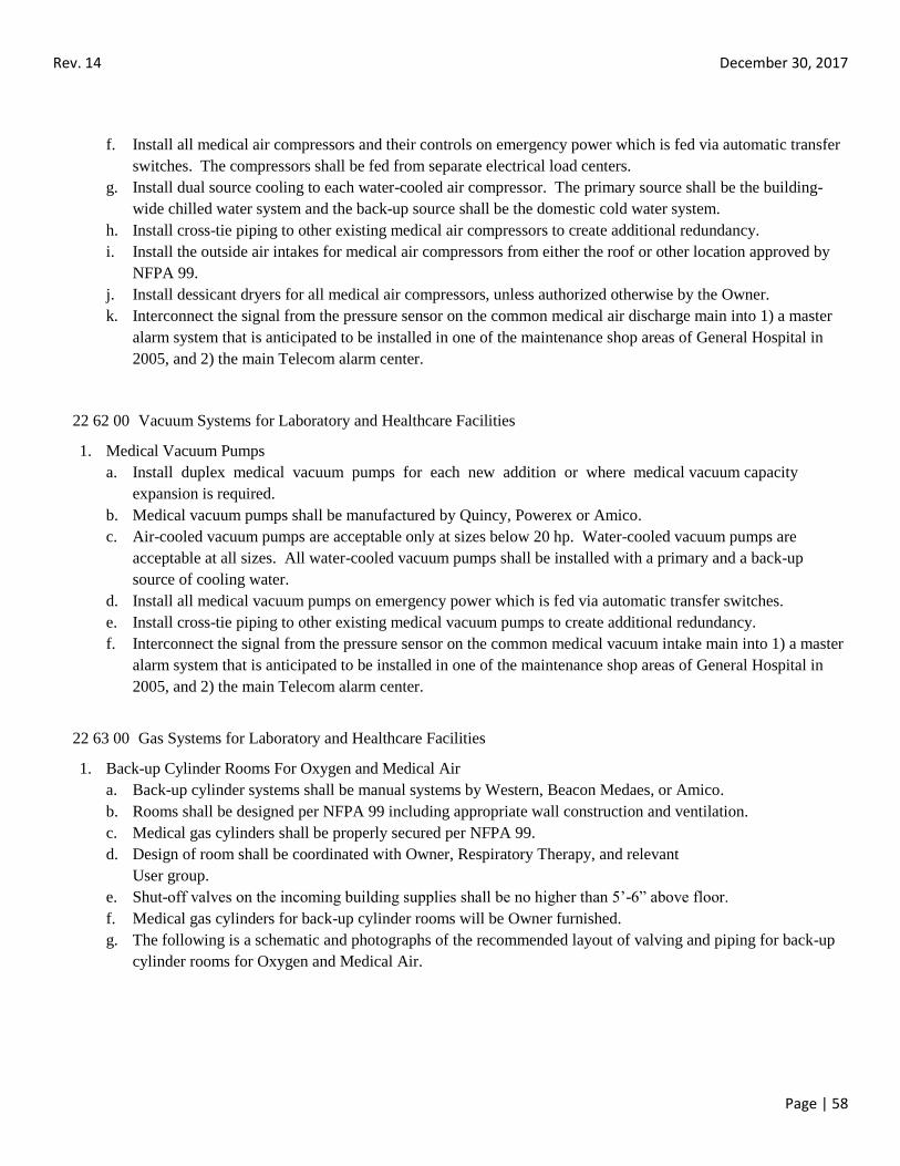
Rev. 14 December 30, 2017
Page | 58
f. Install all medical air compressors and their controls on emergency power which is fed via automatic transfer
switches. The compressors shall be fed from separate electrical load centers.
g. Install dual source cooling to each water-cooled air compressor. The primary source shall be the building-
wide chilled water system and the back-up source shall be the domestic cold water system.
h. Install cross-tie piping to other existing medical air compressors to create additional redundancy.
i. Install the outside air intakes for medical air compressors from either the roof or other location approved by
NFPA 99.
j. Install dessicant dryers for all medical air compressors, unless authorized otherwise by the Owner.
k. Interconnect the signal from the pressure sensor on the common medical air discharge main into 1) a master
alarm system that is anticipated to be installed in one of the maintenance shop areas of General Hospital in
2005, and 2) the main Telecom alarm center.
22 62 00 Vacuum Systems for Laboratory and Healthcare Facilities
1. Medical Vacuum Pumps
a. Install duplex medical vacuum pumps for each new addition or where medical vacuum capacity
expansion is required.
b. Medical vacuum pumps shall be manufactured by Quincy, Powerex or Amico.
c. Air-cooled vacuum pumps are acceptable only at sizes below 20 hp. Water-cooled vacuum pumps are
acceptable at all sizes. All water-cooled vacuum pumps shall be installed with a primary and a back-up
source of cooling water.
d. Install all medical vacuum pumps on emergency power which is fed via automatic transfer switches.
e. Install cross-tie piping to other existing medical vacuum pumps to create additional redundancy.
f. Interconnect the signal from the pressure sensor on the common medical vacuum intake main into 1) a master
alarm system that is anticipated to be installed in one of the maintenance shop areas of General Hospital in
2005, and 2) the main Telecom alarm center.
22 63 00 Gas Systems for Laboratory and Healthcare Facilities
1. Back-up Cylinder Rooms For Oxygen and Medical Air
a. Back-up cylinder systems shall be manual systems by Western, Beacon Medaes, or Amico.
b. Rooms shall be designed per NFPA 99 including appropriate wall construction and ventilation.
c. Medical gas cylinders shall be properly secured per NFPA 99.
d. Design of room shall be coordinated with Owner, Respiratory Therapy, and relevant
User group.
e. Shut-off valves on the incoming building supplies shall be no higher than 5’-6” above floor.
f. Medical gas cylinders for back-up cylinder rooms will be Owner furnished.
g. The following is a schematic and photographs of the recommended layout of valving and piping for back-up
cylinder rooms for Oxygen and Medical Air.
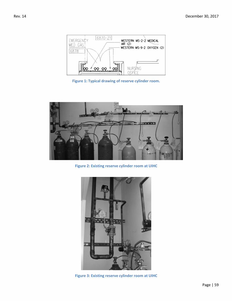
Rev. 14 December 30, 2017
Page | 59
Figure 1: Typical drawing of reserve cylinder room.
Figure 2: Existing reserve cylinder room at UIHC
Figure 3: Existing reserve cylinder room at UIHC
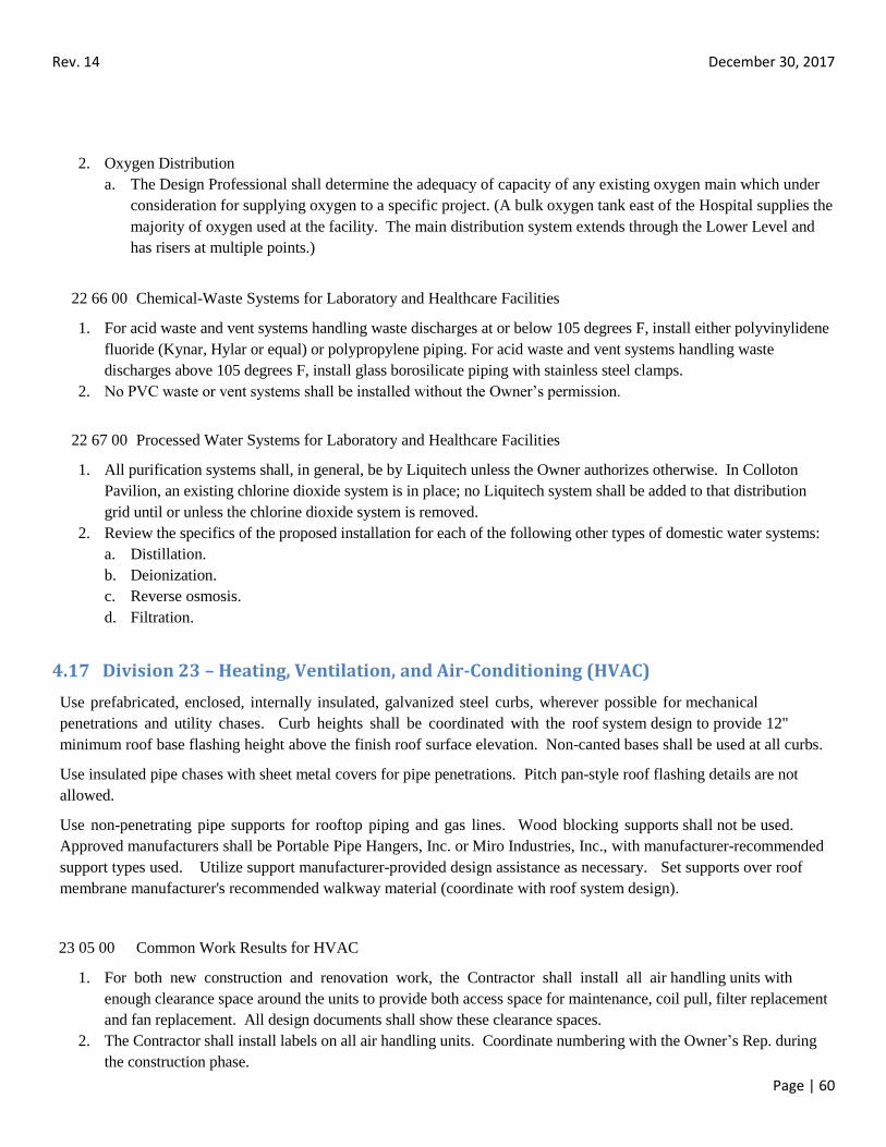
Rev. 14 December 30, 2017
Page | 60
2. Oxygen Distribution
a. The Design Professional shall determine the adequacy of capacity of any existing oxygen main which under
consideration for supplying oxygen to a specific project. (A bulk oxygen tank east of the Hospital supplies the
majority of oxygen used at the facility. The main distribution system extends through the Lower Level and
has risers at multiple points.)
22 66 00 Chemical-Waste Systems for Laboratory and Healthcare Facilities
1. For acid waste and vent systems handling waste discharges at or below 105 degrees F, install either polyvinylidene
fluoride (Kynar, Hylar or equal) or polypropylene piping. For acid waste and vent systems handling waste
discharges above 105 degrees F, install glass borosilicate piping with stainless steel clamps.
2. No PVC waste or vent systems shall be installed without the Owner’s permission.
22 67 00 Processed Water Systems for Laboratory and Healthcare Facilities
1. All purification systems shall, in general, be by Liquitech unless the Owner authorizes otherwise. In Colloton
Pavilion, an existing chlorine dioxide system is in place; no Liquitech system shall be added to that distribution
grid until or unless the chlorine dioxide system is removed.
2. Review the specifics of the proposed installation for each of the following other types of domestic water systems:
a. Distillation.
b. Deionization.
c. Reverse osmosis.
d. Filtration.
4.17 Division 23 – Heating, Ventilation, and Air-Conditioning (HVAC)
Use prefabricated, enclosed, internally insulated, galvanized steel curbs, wherever possible for mechanical
penetrations and utility chases. Curb heights shall be coordinated with the roof system design to provide 12"
minimum roof base flashing height above the finish roof surface elevation. Non-canted bases shall be used at all curbs.
Use insulated pipe chases with sheet metal covers for pipe penetrations. Pitch pan-style roof flashing details are not
allowed.
Use non-penetrating pipe supports for rooftop piping and gas lines. Wood blocking supports shall not be used.
Approved manufacturers shall be Portable Pipe Hangers, Inc. or Miro Industries, Inc., with manufacturer-recommended
support types used. Utilize support manufacturer-provided design assistance as necessary. Set supports over roof
membrane manufacturer's recommended walkway material (coordinate with roof system design).
23 05 00 Common Work Results for HVAC
1. For both new construction and renovation work, the Contractor shall install all air handling units with
enough clearance space around the units to provide both access space for maintenance, coil pull, filter replacement
and fan replacement. All design documents shall show these clearance spaces.
2. The Contractor shall install labels on all air handling units. Coordinate numbering with the Owner’s Rep. during
the construction phase.
Rev. 14 December 30, 2017
Page | 61
3. The air handling unit manufacturer shall be required to provide a minimum of four hours of training for the
Owner’s personnel on each new air handling unit above 2000 cfm.
23 05 53 Identification for HVAC Piping and Equipment
1. Provide equipment identification on all equipment furnished under this division. Where practical, provide plastic
laminate tags indicating the equipment identification number in a clearly visible spot. Where no appropriate flat
surface exists for a plastic laminate tag, provide brass tags on chains attached to the equipment. These equipment
tags are distinct from the Preventive Maintenance numbers that the Owner’s personnel install after the construction
phase.
2. Coordinate all equipment identification numbers with the Owner. It is the Owner’s intent to assign, during the
design phase, plan marks to all equipment items.
3. Install labels on all types of mechanical piping systems. Labels shall be placed at maximum intervals of 50 feet,
near all branch take-offs, and on either side of the walls to patient rooms. Labels shall be color coded as follows:
a. Building service, potable water, cold – light blue, black letters.
b. Building service, potable water, hot – light blue with red band.
c. Hot water recirc – light blue, black letters.
d. Building air – black.
e. Carbon dioxide – gray/black or white.
f. Central piped detergent system – dark grey with white band.
g. Chilled water – dark blue (matching plastic pipe covering).
h. Condensate return – light grey, black letters.
i. Condensing water – aluminum.
j. Cooling tower make-up water – light blue with aluminum band.
k. Distilled water – blue red blue bands.
l. Drain and sludge lines – dark brown.
m. Fire lines – red.
n. Glycol – yellow with blue bands.
o. Heating hot water – medium blue, white letters.
p. Hospital oil-free air – black with green band.
q. Natural gas – vermillion with white band.
r. Nitrogen – black/white.
s. Nitrous oxide – blue/white.
t. Oxygen – green.
u. Rain leaders – dark brown, white letters.
v. Raw water (well water, untreated) – dark grey.
w. Scavenger vacuum (WAGD) – violet/white.
x. Steam, low pressure – orange, black letters.
y. Steam, high pressure – driftwood grey.
z. Vacuum (Cleaning) – dark brown with white band.
aa. Vacuum (Medical) – white/black.
23 05 93 Testing, Adjusting, and Balancing for HVAC
Rev. 14 December 30, 2017
Page | 62
1. General
a. Contracts for testing and balancing are typically separate from the main contracts for general construction in
order to better serve the interests of UIHC. However, coordinate with the UIHC project manager to confirm
the Hospital’s preference for a given project.
b. The Testing and Balancing Contractor (TBC) shall have a minimum of five years’ experience in testing and
balancing and shall be either AABC or NEBB certified
c. The specifications for testing and balancing shall include:
i. The requirement for two season (heating season and cooling season) balancing of central air handling
units.
ii. A warranty period requiring re-adjustment at the Owner’s request of any component that is not
functioning correctly for a period of 90 days following initial balance.
iii. The requirement for adjusting the system to accommodate comments made by the Design
Professional on the balancing report.
iv. A minimum of five copies of the balancing report shall be submitted.
2. Pre-Construction Testing
a. Pre-construction testing (also known as benchmarking) shall be considered where renovation or new
construction shall impact airflows or hydronic flows or parts of existing mechanical systems that shall remain.
Pre-construction airflow testing is beneficial where renovation or new construction, without pre-construction
testing, would either:
i. Cause unnecessary disruption to nearby occupants due to the need to rebalance multiple downstream
terminals, or
ii. Create additional overall costs for balancing work at the end of the project.
3. Design Phase Coordination
a. For phased work, the Design Professional shall meet with one of the possible TBC during the design phase to
give input into the requirements of the project, including the proposed locations of balancing dampers,
balancing valves, and autoflow valves.
b. For phased work, the same TBC shall be used for all phases of the project.
c. The Owner may, depending upon the size and complexity of the project, retain the services of a TBC to
review the 90% review documents to coordinate the optimum placement of dampers, valves, pressure taps,
etc. and to minimize any balancing- related change orders.
d. The specifications shall require that the General Contractor and all subcontractors fully cooperate with the
TBC during the construction phase and during initial occupancy.
e. The specifications shall also require that the TBC fully cooperate with the General
Contractor and the Testing and Balancing Contractor.
4. Airflow Testing and Balancing
a. Specialty balancing items:
i. All air handling units which have been retrofit with ultraviolet emitters shall be rebalanced 45 days
after the emitter installation. The 45 day waiting period will allow the cooling coil to clean itself,
creating a lower air pressure drop across it.
ii. The TBC shall coordinate the calibration of all airflow monitors, isolation rooms, and pressure-
controlled rooms with the Temperature Controls Contractor.
Rev. 14 December 30, 2017
Page | 63
5. Hydronic Testing and Balancing
a. Specialty balancing items:
i. Branch lines for recirculating domestic hot water shall be balanced by the TBC to ensure flows.
ii. Note that the Mechanical Piping Section requires that HVAC pumps have:
A single pressure gauge connected directly at the suction and discharge outlets of the pump.
An accurate type of flow measurement device (such as a venturi or sharp edge orifice) if testing
and balancing is required at a specific pump. Triple-duty valves do not proved accurate
enough flow measurements.
6. Sound Level Testing
a. Sound level testing shall be specified only in areas where the UIHC project manager deems sound levels to be
a critical issue. Selection of the areas to be tested shall be made during the design phase.
b. Sound level testing shall be based upon ANSI 224.3. NC curves shall be developed by the TBC for inclusion
in the sound level report.
23 07 13 Duct Insulation
1. Do not install exposed duct lining on supply or return air ducts unless authorized by the Owner.
2. Double wall duct (solid outer and inner liners with insulation between) shall be specified on supply air ducts
(and on return air ducts where insulation is required) within Mechanical Equipment Rooms and on risers in
main chases.
3. Specify rigid insulation or insulation wrap at other locations for supply air ducts and, where deemed necessary, for
return air ducts. Rigid insulation shall be installed using both adhesives and welded pins.
23 07 19 HVAC Piping Insulation
1. Insulate all mechanical piping systems per ASHRAE 90.1.
2. Jacketing:
a. For typical mechanical piping systems, use fiberglass insulation with all-service jacketing.
b. Install additional jacketing at locations where physical protection is required.
c. Install PVC jacketing on all piping within Mechanical Equipment Rooms.
d. Install aluminum jacketing for insulated piping outside the facility and at locations where maintenance access
may cause damage.
e. Review with the Owner specific types of jacketing proposed for each installation.
23 08 00 Commissioning of HVAC
1. Include the TBC on any projects where formal commissioning is specified.
2. A Certified AABC Commissioner shall be part of any commissioning team.
23 09 00 Instrumentation and Controls for HVAC
1. General
a. A majority of the existing temperature control systems within the facility are currently based upon the
Johnson Controls Metasys system. However, Johnson Controls and Siemens are now approved TCCs at the
Rev. 14 December 30, 2017
Page | 64
Hospital. However, there are locations where the required new systems of one TCC would work better with
the existing equipment than others. The Design Professional shall review such areas with the Owner’s Rep.
b. The Design Professional shall coordinate all new temperature control work with any existing systems.
2. Temperature Control System Requirements
a. Electrical wiring:
i. All 24 volt wiring shall be installed by the TCC. This wiring shall be installed either in conduit or on
J hooks. In mechanical equipment rooms and in patient rooms, the use of conduit is required.
Routings shall be above corridor ceilings.
ii. All 120 volt wiring for temperature control work (such as to control panels and for terminal air box
controls) shall be installed by the TCC. This wiring shall be installed in conduit.
3. Pneumatic air piping:
a. Exposed locations: Hard copper tubing.
b. Concealed inaccessible locations: Either hard or soft copper tubing.
c. Concealed accessible locations: Copper tubing.
d. Buried in concrete: Either hard or soft copper tubing.
e. Inside control panels and enclosures: Polyethylene tubing.
f. Penetrations through fire and smoke barriers (walls and floors): Either hard or soft copper tubing.
g. Removal of all pneumatic tubing not needed for the project. Terminated at hard copper with approved brass
plugs or caps, and leak tested.
4. Areas requiring special control systems
a. Isolation rooms shall have volume matching terminal air boxes on the supply and the return or exhaust for
that room. The current standard for control monitors on isolation rooms is the TSI model Pressura RPC
30. The TCC shall be specified to provide both monitoring and control of all exhaust fans for isolation
rooms.
b. Telecom rooms shall be designed with their own thermostats which shall control a terminal air box, fan
coil or other cooling device.
5. Equipment which requires standardized control or monitoring systems.
a. Terminal Air Boxes (TABs) shall be specified with a discharge air sensor. The TCC shall be specified to
provide the reheat coil control valve, the damper actuator, the transformer, the controller and the thermostat.
For each project, the specifications shall clearly identify which subcontractor is to provide the mounting of
the actuators.
b. Fire/smoke dampers shall have end switches and actuators mounted by the damper manufacturer.
Connection of the signal from all fire/smoke dampers to the fire alarm system shall be by the TCC. Actuators
shall be 120V. Wiring for fire/smoke dampers shall be similar to that shown on wiring diagram attached to
this document. Power to the control system itself shall be by the TCC.
c. Chilled water coils at main air handlers shall have pressure independent Delta P control valves. The
temperature control system shall monitor entering water temperature, leaving water temperature, and valve
position.
d. All return and exhaust fans shall be monitored. Review with the Owner those locations where pressure
monitoring is also required.
e. VFDs shall be Toshiba or ABB. No other manufacturers shall be allowed unless authorized by the
Owner. The General Contractor shall provide the VFD to better coordinate the VFD/control system
compatibility.
Rev. 14 December 30, 2017
Page | 65
f. HVAC circulating pumps shall be monitored and controlled. Monitoring by either circuit transformers or
differential pressure switches are acceptable.
g. Sewage ejectors shall be monitored for high level alarm and pump failure status.
h. Sump pumps shall be monitored for high level alarm and for pump status. Clearly specify which
subcontractor is to provide and install the float switch.
i. Emergency generators shall be monitored for run status. This monitoring is separate from the monitoring
provided by the generator remote panels.
6. Design Phase Coordination
a. The Design Professional shall, during the design phase, coordinate with the Owner in order to access the
expertise and historical knowledge of systems in use at UIHC. This coordination effort shall be during a
formal project meeting.
b. Discuss with the Owner’s Rep. all temperature control work that may merit a longer warranty period than is
standard. Unless otherwise authorized by the Owner, all temperature control systems shall be provided with
a one year warranty. For projects with multiple phases, review with the Owner, the starting point of all
warranties.
c. The Design Professional shall, for each specific project, ask the Owner whether video-taping of the
temperature control system training is required.
d. Coordinate all temperature control point names with the Owner.
7. Construction Phase Coordination
a. Work to be specified for the General Contractor to provide under the supervision of the TCC:
i. Provide and install all valves, pressure taps, and connections for steam water, drain and overflow
connections.
ii. Provide and install all piping connections required for valve position indicators, flow devices, etc.
iii. Provide and install any necessary access panels to allow service access to all control devices and
equipment.
iv. Provide and install any necessary multiple section dampers and interconnecting linkages.
v. Install any automatic dampers and automatic control valves that are to be furnished by the
TCC.
vi. Install any separable wells that are to be furnished by the TCC.
b. The TCC shall be contractually required to fully coordinate with the Testing and
Balancing Contractor.
c. For each project, the number of training hours for Hospital personnel shall be clearly specified.
23 11 00 Facility Fuel Piping
23 11 13 Facility Oil Systems
1. Review the specifics of the proposed system with the Owner.
23 11 23 Facility Natural Gas Piping Systems
1. Review the specifics of the proposed system with the Owner.
Rev. 14 December 30, 2017
Page | 66
23 20 00 HVAC Piping and Pumps
1. General
a. For both new construction and renovation work, install all mechanical pipes as high as possible (while
allowing for maintenance access) to prevent any existing or future ceilings from being forced too low.
b. Routings of mechanical piping shall be parallel or perpendicular to building lines. All piping installed in
chases shall be designed to allow future installation of additional vertical risers and, at the bottom of the
chase, additional horizontal piping associated with future projects.
c. Install horizontal sections of mechanical piping mains above-ceiling in corridors unless authorized
otherwise by the Owner.
d. All above-ceiling sections of branch lines shall be at least ¾” diameter to allow for future capacity additions.
Terminal runs in walls and to fixtures may be less than ¾” diameter.
e. Provide isolation valves on all branch lines and on all equipment. The Design
Professional shall specify, and then field verify, that all new valves are accessible.
f. Pipes shall not be routed over electrical equipment rooms and Telecom closets unless authorized otherwise by
the Owner.
g. Where mechanical piping risers span more than two floors, those risers shall be installed inside of fire-rated
chases.
h. Do not install mechanical piping:
i. Within 18” inches horizontally of any pneumatic transport tube diverter.
ii. Below any pneumatic transport tube diverter.
iii. Within 18” horizontally of any terminal air box.
iv. In the door swing space of any duct access door.
v. Within 12” of the front of any electrical junction box.
vi. Within 12" of any roof perimeter or penetration requiring roof flashing.
vii. Within 4" of the new roof surface elevation.
i. Install brass unions connections in the mechanical piping systems where any dissimilar metals are in
contact.
j. All valves shall be tagged unless valves are ¾” in diameter and adjacent to equipment served. Valve tags
shall include the valve number and project number. Coordinate the specific numbering sequence with the
Owner’s Rep. during the construction phase of each project.
k. All types of mechanical piping risers, except cooling coil condensate and refrigerant piping, shall have drain
valves at their bottom as well as isolation valves on their horizontal supply and return branches where they
connect to their risers.
l. Pressure Testing
i. Pressure testing is required on all piping systems.
ii. All pressure tests shall be witnessed and/or signed off by the Owner.
iii. The Contractor shall provide seven days advance notice of all pressure testing.
iv. The Contractor shall provide new valves as required to perform pressure testing of segments of new
piping.
Rev. 14 December 30, 2017
Page | 67
23 21 00 Hydronic Piping and Pumps
Chilled Water Piping Systems
1. UIHC Chilled water design criteria
a. Cooling coil selection shall be based upon 14 degrees temperature difference between the entering chilled
water and the leaving chilled water, unless authorized otherwise by the Owner. (High humidity removal
conditions could dictate a lower delta T be used as the design basis.)
b. The cooling coil control valve shall be an industrial quality, pressure independent valve with 100 to 1
rangeability and an electronic actuator.
c. Cooling coil control valves shall be Delta P valves by Flow Control Industries, unless otherwise authorized by
the Owner’s Rep.
d. Information system points
i. Service entrances (from the U of I campus chilled water system) shall include points for supply
temperature, return temperature, supply pressure, and return temperature.
ii. The main building distribution system shall include points for supply temperature (one per building),
return temperature, supply pressure, return pressure, flow into the building system, and pressure at the
hydraulically most remote point in the building.
e. Each cooling coil shall include points for valve position feedback (for Delta P valves)
and return temperature.
f. Designs that make modifications to the interface for building chilled water shall be coordinated with U of I
Chilled Water Plant.
2. Materials
a. For interior chilled water piping above 2 inch diameter, install either:
i. Schedule 40 ASTM A53 seamless black steel with welded or mechanically coupled joints.
ii. Type K ASTM B88 copper with wrought fittings.
b. For interior chilled water piping 2 inch diameter or less, install either:
i. Schedule 40 ASTM A53 seamless black steel with screwed or welded joints.
ii. Type K ASTM B88 copper with wrought fittings.
3. Chilled water pumps
a. The Design Professional shall not specify the installation of additional chilled water pumps without Owner
approval.
b. All necessary floor-mounted chilled water pumps shall be installed on concrete housekeeping pads.
c. Install a single oil-filled pressure gauge directly at the suction and discharge outlets of each pump.
4. Air separators
a. Clean all integral strainers at the end of each construction project that connects to a given chilled water
grid.
5. Insulation and jacketing
a. Install vapor barriers on all piping insulation for chilled water systems.
6. Other
a. Install manual air vents at accessible locations
i. At the top of all risers.
ii. At all high points in the piping system.
iii. But not in patient rooms.
b. Install plate heat exchangers where higher quality chilled water is required for protection of sensitive
equipment.
Rev. 14 December 30, 2017
Page | 68
Heating Hot Water Piping Systems
1. Materials
a. For interior heating hot water piping above 2 inch diameter, install either:
i. Schedule 40 ASTM A53 seamless black steel with welded joints.
ii. Type K ASTM B88 copper with wrought fittings.
b. For interior heating hot water piping 2 inch diameter or less, install either:
i. Schedule 40 ASTM A53 seamless black steel with screwed or welded joints.
ii. Type K ASTM B88 copper with wrought fittings.
c. Mechanically coupled piping shall not be used.
2. Heating hot water pumps
a. All floor-mounted heating hot water pumps shall be installed on concrete housekeeping pads.
b. Install a single oil-filled pressure gauge directly connected to the suction and discharge outlets of
each pump.
3. Other
a. Install manual air vents at accessible locations
i. At the top of all risers.
ii. At all high points in the piping system.
iii. But not in patient rooms.
23 21 14 Hydronic Specialties
Mechanical Piping Specialties
1. Balancing valves shall be provided with multiple stops. Ball valves are not acceptable for balancing.
2. For strainers above 2” diameter, provide with ball valve flush assembly. All strainers shall be cleaned at the end of
any construction phase. The Contractor shall submit an end-of-construction report certifying that all strainers have
been cleaned.
3. All relief valves shall be piped to a floor drain. Route all relief piping through areas such that no blockages of
traffic paths are created.
4. Griswold space-saver type control valves shall not be used. The following shall be the standard: Hammond ball
valves and strainers, and Bell & Gossett circuit balancing valves.
Glycol Piping Systems
1. Materials
a. For interior glycol piping above 2 inch diameter, install either:
i. Schedule 40 ASTM A53 seamless black steel with welded joints. Where threaded joints must be used
due to equipment connections, install with Teflon tape. The Design Professional shall specify all
Teflon tape, gaskets, and other sealants that are totally compatible with the glycol and inhibitor to be
used in the system.
ii. Type L ASTM B88 copper with wrought fittings. Screwed fittings shall not be used.
b. For interior glycol piping 2 inch diameter or less, install either:
i. Schedule 40 ASTM A53 seamless black steel with welded joints.
ii. Type L ASTM B88 copper with wrought fittings.
2. Other
a. Install manual air vents at accessible locations
Rev. 14 December 30, 2017
Page | 69
i. At the top of all risers.
ii. At all high points in the piping system.
iii. But not in patient rooms.
b. Install low pressure alarms on glycol piping systems to sense any leakage from the system. The low pressure
alarm signal shall be monitored by the building automation system. Do not install automatic make-up water
connections to glycol piping grids due to the danger of dilution of the glycol/water mixture (and hence
potential freezing).
Cooling Coil Condensate Piping Systems
1. Materials
a. Install Type L ASTM B88 copper with wrought fittings.
2. Routings
a. The cooling coil or air handling system shall be installed as high as necessary to avoid having to construct a
trap that would extend through the floor into a level below. If a condensate trap assembly is unavoidable,
completely seal against water leaks through the floor penetration.
b. Minimize the lengths of condensate pipes installed on the floors of Mechanical
c. Equipment Rooms.
3. Insulation
a. Insulate all condensate lines that extend through occupied spaces or the above-ceiling areas over occupied
spaces.
23 21 23 Hydronic Pumps
1. Circulating Pumps
a. Install all floor-mounted circulating pumps on concrete housekeeping pads.
b. Include means to manually balance each circulating pump. Triple-duty valves shall not be used for balancing.
c. Include pressure taps directly at the suction and discharge ports of each pump for accurate measurement of
pressures.
d. Parallel pumps with unequal heads shall not be specified.
23 22 00 Steam and Condensate Piping and Pumps
1. UIHC Steam Design Criteria
a. Designs that make modifications to the building steam system shall be coordinated with U of I Physical Plant.
b. Information system points
i. On steam mains downstream of each service entrance (from the U of I campus steam distribution
system) monitoring points shall include points for steam pressure and temperature, both upstream
and downstream of the PRV.
ii. Monitoring of the condensate pump status and level alarms.
iii. Monitoring of the end sections of major steam grids is desirable.
iv. The Design Professional shall include all of the required information system points in any upgrade
or new work associated with the identified portions of the steam piping system.
2. Materials
a. For interior steam and condensate piping with pressures (below 75 psig), and above 2 inch diameter, install
either:
Rev. 14 December 30, 2017
Page | 70
i. Schedule 40 ASTM A53 seamless black steel with welded joints.
ii. Type L ASTM B88 copper with wrought fittings.
b. For interior steam and condensate piping with pressures below 75 psig, and 2 inch diameter or less, install
either:
i. Schedule 40 ASTM A53 seamless black steel with screwed or welded joints.
ii. Type L ASTM B88 copper with wrought fittings.
c. For interior steam and condensate piping with pressures 75 psig and higher, and above 2 inch diameter,
install Schedule 80 ASTM A106 GrB seamless black steel with threaded forged steel 2000# Class fittings.
d. For interior steam and condensate piping with pressures below 75 psig, and 2 inch diameter or less, install
Schedule 40 ASTM A106 GrB seamless black steel with standard butt welded fittings.
3. Condensate Pumps
a. Only duplex condensate pumps shall be installed.
b. Any condensate receiver which is not recessed nor on elevated legs shall be installed on a concrete
housekeeping pad.
c. Design basis shall be electric condensate pumps. Review with the Owner the importance of installing steam-
powered condensate return pumps wherever such are proposed for new construction.
4. Pressure Reducing Valve (PRV) Assemblies
a. Pressure Reducing Valves (PRVs) at service entrances shall be eccentric plug control valves by Cashco
Ranger. These valves shall have either steel or ductile iron bodies. Coordinate with the University FSG for
the specification and purchase of these valves. FSG maintains, and where necessary, rebuilds the PRVs at
service entrances.
b. Any PRVs downstream of the service entrance PRVs are owned and maintained by
UIHC.
c. All PRV assemblies shall be provided with:
i. A three-valved bypass assembly.
ii. Dial type pressure gauges on both the upstream and downstream sides.
5. Valves
a. All gate valves shall be 300 # class.
b. For steam and steam condensate valves above 2 inch diameter, all gate valves shall be butt welded. Flanged
valves are not acceptable.
c. For steam and steam condensate valves 2” diameter and less, all gate valves shall be screwed bronze.
6. Other
a. Drain valves shall be installed at the bottom of all risers and at all steam main isolation valves.
b. Air bleed valves shall be installed at high points of steam condensate lines.
23 23 00 Refrigerant Piping Systems
1. System Design
a. The Design Professional shall provide in the construction documents a detailed piping layout of all field-built
refrigerant piping systems. These layouts shall include all required pipe sizes, traps, double risers, and
refrigerant accessories.
2. Insulation And Jacketing
a. A weather-resistant covering or field-applied paint shall be applied on all exterior pipe insulation.
b. Vapor barriers shall be applied to all return line insulation.
Rev. 14 December 30, 2017
Page | 71
23 25 00 HVAC Water Treatment Systems
1. All chilled water is chemically treated by the University of Iowa chilled water system.
Review the proposed chemical treatment program with the Owner to determine compatibility with the
on-going chemical treatments.
2. For all other hydronic mechanical piping systems, pressure test, chemically treat, flush and drain all new
systems.
23 30 00 HVAC Air Distribution
1. Isolation Rooms
a. Label the exhaust air duct from isolation rooms at intervals of 50 feet. Also label each isolation room
exhaust fan, motor controls and any VFDs as such.
b. Arrange the duct systems for isolation rooms to include flow tracking (for pressurization control) via
the use of TABs on both the incoming supply air and the leaving exhaust or return air ducts.
c. Isolation rooms shall have direct drive exhaust fans.
d. The return or exhaust intakes from isolation rooms shall be installed at floor level and filtered with pleated
Meril 8 filter.
e. The room pressure controller for isolation rooms shall be a TSI model RPC30 with a non-flashing display.
f. Isolation rooms shall have either neutral/negative switching or neutral/positive switching; negative/positive
switching is prohibited.
g. Ceiling diffusers with integral HEPA filters (in lieu of installing above-ceiling in-line
HEPA filters) shall be used for positive pressure isolation rooms.
h. Locate all ceiling diffusers such that they do not interfere with the wall-mounted inlet for the room pressure
controller.
23 31 00 HVAC Ducts and Casings
23 31 13 Rigid Metal Duct Systems
1. Show pressure classification of all duct systems on both the design documents and the ductwork shop
drawings.
2. Seal all duct joints and seams to minimize duct leakage.
3. Specify the acceptable leakage criteria for each duct system. Specify pressure testing of all newly-installed duct
mains for leakage prior to placing into service.
4. Design all duct support systems, including concrete inserts, hangers, rods, etc., to support
4 times the calculated weight of the duct section (and any adjacent fans).
5. Support all ducts directly from the structure.
6. Duct systems shall be clean/cleaned prior to acceptance by the Owner.
23 32 00 Air Plenums
1. Floor-mounted plenums shall have full-height access doors.
23 33 00 Air Duct Accessories
1. Sound Attenuators
a. Specify sound attenuators wherever required on main air handling and exhaust systems.
b. Specify sound attenuators on the downstream side of all terminal air boxes.
Rev. 14 December 30, 2017
Page | 72
c. Air handling units shall not be installed on the same floor as or in adjacent spaces to occupied spaces without
incorporating adequate sound attenuation materials into the intervening duct and wall construction.
23 33 13 Dampers
1. Fire/Smoke Dampers
a. F/S dampers shall be provided with end switches and mapped back to the BAS.
b. Coordinate all control system voltages and smoke damper operator voltages.
Typically fire/smoke dampers are provided with 120 volt actuators, with a test switch located at the damper.
c. F/S dampers shall be installed in a manner that is accessible for testing and inspection.
2. Fire Dampers
a. Fire dampers shall be Style B construction with the damper blades out of the air stream unless otherwise
authorized by Owner.
b. Fusible links shall
c. Fire dampers shall be installed in a manner that is accessible for testing and inspection. The access door
should be as large as possible to get both arms in the duct to replace a fusible link.
3. Balancing Dampers
a. Primary volume dampers shall be provided in the duct branch that serves the diffuser or register. Provide
individual volume dampers at each diffuser or register for minor adjustments.
b. The Design Professional shall, during the design phase, meet with the anticipated Testing and Balancing
Contractor, and review the adequacy of the location and number of balancing dampers for each duct
system.
23 33 46 Flexible Ducts
1. Flexible duct sections shall have a maximum length of five feet.
23 34 00 HVAC Fans
1. Return Fans
a. Return fans shall have variable speed controllers wherever supply fans are controlled by VFDs.
b. For ganged return fans and exhaust fans, provide tight-sealing isolation dampers to completely block
airflows during maintenance and backdraft dampers for normal operation periods.
2. General Exhaust Fans
a. Status monitoring shall be provided for all exhaust fans.
b. Internal sound attenuation lining up to 40 feet upstream of the fan inlet is acceptable.
23 36 00 Air Terminal Units
1. Terminal Air Boxes (TABs) shall have electronic actuators.
2. TABs shall have direct digital controls, including discharge supply air temperature, damper position, reheat
coil valve position, and air volume.
3. TABs which require heating shall have two row heating coils.
4. All TABs shall be provided with variable air volume capability, even if the specific unit is designed for constant
volume airflow.
23 37 00 Air Outlets and Inlets
Rev. 14 December 30, 2017
Page | 73
23 37 13 Diffusers, Registers and Grilles
1. Carefully review locations of each diffuser and register to avoid drafts on patients in each patient room.
2. 2. Supply and Return diffusers shall be white Model SPD Square Plaque Diffuser.
23 38 16 Fume Hood Exhaust Fans
1. Provide durable, weatherproof flexible connections at inlets.
23 70 00 Central HVAC Equipment
1. General
a. All air handling units shall be the draw-thru type unless a heating hot water coil is installed downstream
of the chilled water coil. Blow-thru units shall be avoided because of the potential for moisture carry over
and condensation on the filter media.
b. Specify extra capacity on all components within the air handling unit to provide future flexibility for the
spaces to be served. Review with the Owner the magnitude of the extra capacity to be specified on each
project.
c. For air handling units not located on slab on grade, locate all units to eliminate the need to extend
condensate traps through the floor.
2. Housings
a. Specify Type 304 stainless steel liners throughout the entire unit.
b. Specify all interior air handling units on a concrete housekeeping pad, at least 4 inches high.
3. Fans
a. Fan array systems shall be specified on all units serving patient rooms or other critical areas.
b. All supply fans above 2000 cfm shall be furnished with variable frequency drives (VFDs). Only Toshiba
and ABB are acceptable unless authorized otherwise by the Owner.
c. At project completion, the Contractor shall turn over a set of normal replacement parts for each fan,
including belts.
d. Vortex dampers shall not be used at the fan inlet.
4. Cooling Coils
a. Cooling coil selection shall be based upon 14 degrees temperature difference between the entering chilled
water and the leaving chilled water, unless authorized otherwise by the Owner.
b. Stainless steel drip pans shall be employed for all air conditioning condensate.
Condensate pans and/or air handling units shall not be installed so low as to require the trap in the
condensate line to penetrate the floor level.
c. Delta P control valves shall be specified. Refer to the Mechanical Piping Section of this standard.
d. Position of control valves shall be monitored. Refer to the Temperature Controls
Section of this standard.
e. Dual drainage lines shall be specified from all condensate drip pans to the nearest discharge point (usually
this will be a floor drain).
5. Steam Heating Coils
a. Steam heating coils shall have integral face and bypass dampers.
b. Steam heating coils shall be capable of a 80 degree F air temperature rise (-25 degrees
F to 55 degrees F).
6. Heating Hot Water Coils
Rev. 14 December 30, 2017
Page | 74
a. Heating hot water coils are acceptable for heating coils installed downstream of the steam heating coil.
Heating hot water coils shall not be used for primary heating in air handling.
7. Pre-Filter Sections
a. Filters shall be of the preformed, pleated type.
b. All filter racks shall be gasketed.
c. Typically pre-filters are 30% efficient minimum.
d. Filter access doors shall be specified on both sides of the filter section.
e. Roll filters are not acceptable for pre-filters.
f. At project completion, the Contractor shall replace all filters.
8. Final Filter Sections
a. All filter racks shall be gasketed.
b. Final filters shall be 95% efficient, unless HEPA filters are required for
the spaces being served.
c. Filter access doors shall be specified on both sides of the filter section.
d. Bag filters shall not be used for final filters.
e. Design phase selection of coil velocity shall be checked to ensure that moisture does not carry over into the
filter section.
f. At project completion, the Contractor shall replace all filters.
9. Blender Sections
a. Specify blender sections for the mixing of return air and outside air within each air handling unit if space
is available.
b. Arrange duct systems for head-on mixing of the outside air and return air streams.
Also align the control dampers in the outside and return air streams for maximum mixing.
10. Mist Eliminators
a. Mist eliminators shall be specified where there is potential moisture carryover and in all air handling systems
where the design velocity across the cooling coil is over 500 fpm.
11. Anti-Microbial Ultraviolet Emitters for HVAC Ducts and Equipment
a. Provide an automatic switch to de-energize the emitters whenever an access door immediately on either side
of the cooling coil is opened.
b. A service switch shall be included to manually de-energize the emitters.
c. A radiometer shall be specified to measure the relative output of each system. The radiometer shall be set
to 100% as soon as the emitters are operational.
d. The lamps shall have a separate power source so that the lamps are always energized regardless of the
operation of the air handling unit.
e. The primary set of lamps shall not be installed until after the air handling unit has been completed and
cleaned.
f. At project completion, the Contractor shall provide a complete set of replacement lamps.
12. Humidifiers
a. Steam-to-steam humidifier(s) shall be included for each air handling unit. Refer to AIA Guidelines for
suggested humidity levels.
b. Domestic hot water shall be used for the humidifier make-up, except in Colloton and Carver Pavilions where
special water treatment generates chlorine dioxide or copper and silver ions in the water streams.
Rev. 14 December 30, 2017
Page | 75
c. Two humidistats shall be used to control the humidifier. One humidistat shall be located in the return air
duct and one high limit humidistat shall be located in the supply air duct. Note that there are special care
areas, such as surgery where the humidity sensor shall be located in the occupied area.
13. Miscellaneous
a. For ganged air handling unit systems, specify tight-sealing isolation dampers to completely block
airflows during maintenance, and backdraft dampers for normal operation periods.
b. Low leakage dampers with quality seals shall be specified for the mixed air and outside air ducts.
c. Linkages for all actuators shall be specified at an angle to allow full closure.
23 83 16 Radiant Heating
1. Radiant ceiling panel systems shall be designed for heating only.
2. In all patient rooms, install radiant heating panels at the exterior walls. The radiant panels shall be installed near
each window associated with a patient room. Radiant panels may also be installed in patient toilets.
3. Valves
a. Use only two-way control valves for radiant heating panels. Do not use any three- way control valve
schemes for temperature control of radiant panels.
4. Heating Hot Water
a. The heating hot water service to all radiant panels shall be maintained at or below the maximum temperature
recommended by the radiant panel manufacturer.
b. The heating hot water service to all radiant panels shall be adjustable to allow reduced temperature heating
hot water being supplied at different times of the year. Take precautions during the Design Phase to
minimize noise in radiant ceiling panel systems.
4.18 Division 26 – Electrical
Use prefabricated, enclosed, internally insulated, galvanized steel curbs, wherever possible for utility chases. Curb
heights shall be coordinated with the roof system design to provide 12" minimum roof base flashing height above the
finish roof surface elevation. Non-canted bases shall be used at all curbs.
Use insulated pipe chases with sheet metal covers for pipe penetrations. Pitch pan-style roof flashing details are not
allowed.
Use non-penetrating pipe supports for rooftop conduits, raceways, cable trays, etc. Wood blocking supports
shall not be used. Approved manufacturers shall be Portable Pipe Hangers, Inc. or Miro Industries, Inc., with
manufacturer-recommended support types used. Utilize support manufacturer-provided design assistance as
necessary. Set supports over roof membrane manufacturer's recommended walkway material (coordinate with roof
system design).
26 05 00 Common Work Results for Electrical
1. Designs that involve changes to the electrical supply that will affect utility service shall be coordinated with UI
Utilities and Energy Management Department.
2. Electrical Closets
a. The finished flooring in electrical closets shall be concrete sealed for dust control.
26 05 13 Medium-Voltage Cables (Wire)
1. General
Rev. 14 December 30, 2017
Page | 76
a. Minimum size wiring for power applications shall be #12 unless the distance is greater than 100’, then it shall
be #10 Stranded.
b. 120/208 volt normal, 120/208 volt emergency, 277/480 volt normal, 277/480 volt emergency,
communications, and Fire Alarm wiring shall not occupy the same raceway.
c. For high harmonic branch circuits such as those serving lighting and electronic equipment, provide a
shared #10 neutral conductor for three phase conductors. For sensitive electronic and diagnostic equipment,
provide a separate #12 neutral conductor for each phase conductor. For branch circuit panels serving high
harmonic loads, provide double-sized neutral conductor.
d. Type AC (armored cable) and type MC (metal clad cable) shall not be specified.
2. Type of Wire and Connectors
a. All wire and cable for power, lighting, control and signal circuits shall have copper conductors and shall be
insulated to 600 volts. Conductor sizes #12 AWG and smaller shall be solid; conductor sizes #10 AWG and
larger shall be stranded. All standard building wiring shall be THWN/THHN. Aluminum conductors are not
allowed.
b. In-line splices and taps for conductor sizes #8 AWG and smaller, shall use vinyl insulated spring connectors.
Connectors for conductors sizes #6 and larger shall be compression lug types.
c. Conductor identification-all circuits originating from 20 amp circuit breakers shall have the grounded
conductor identified by a colored tracer of the same color as the ungrounded conductor.
d. Color code conductors as follows:
i. 120/208V, 3PH, 4W: Phase A – Black; Phase B – Red; Phase C – Blue; Neutral – White; Ground –
Green.
ii. 277/480V, 3PH, 4W: Phase A – Brown; Phase B – Orange; Phase C – Yellow; Neutral – Grey;
Ground – Green.
iii. Grounded connectors require colored tracer that is the same color as the phase conductor.
3. Installation
a. All cable for major feeders shall be continuous from origin to termination. Splices in branch circuit wires
shall be made only in accessible junction boxes. Keep conductor splices to a minimum.
b. All power feeder cable shall be pulled with the use of approved pulling compound or powder. Pull all
conductors into raceway at the same time.
c. Neatly arrange, label, and tie-wrap all wiring inside all cabinets, panelboards, boxes, and other enclosures.
26 05 26 Grounding and Bonding for Electrical Systems
1. General
a. All equipment, lighting, devices, and metallic conduit systems shall be grounded per NEC 250, NEC 517,
and NFPA 99.
b. Maximum resistance of main service grounds shall be 3 ohms.
c. In new service applications, the main electrical service ground shall be connected to the incoming water
service, a new grounding grid, building steel, and steel rebar in the foundations.
d. The grounding grid shall consist of ground rods spaced 10’-0” apart, connected with exothermic welds, in
addition to conductors installed in the transformer vault walls. Coordinate main grounding with the Electrical
Distribution Department.
e. In the older portions of the facility (Boyd Tower, General Hospital, and South Wing), a separate grounding
conductor is not always present in feeders and branch circuits. In remodel projects where existing panels are
reused, proper grounding of that panel shall be obtained by bonding the feeder conduit serving the panel at the
Rev. 14 December 30, 2017
Page | 77
panel, all pull boxes, and the source panel; or by re-pulling a new feeder with a separate grounding conductor
if the panel will serve sensitive electronic or diagnostic equipment. Branch circuit wiring with no grounding
conductor shall not be reused for new circuits.
f. Where new panels are added, the feeders to the source panel shall contain a grounding conductor.
The source panel shall be properly grounded back to the main electrical service if proper grounding does not
currently exist.
g. A grounding electrode conductor shall be extended to all step-down transformers from the main
electrical service ground bar. This shall be used to ground the secondary neutral. The equipment
grounding conductor is NOT the grounding electrode.
h. Isolated ground panels shall be used in areas with sensitive equipment such as electronics, hospital diagnostic
equipment, and computer equipment. A separate isolated grounding conductor (green with a yellow
stripe) shall be installed in the panel feeder and all branch circuits. A green grounding conductor shall also
be installed to bond the panel enclosure.
i. Sensitive electronic and imaging equipment often require a very “clean” grounding connection. Provide a
dedicated grounding conductor to main electrical service grounding point and provide for monitoring of
ground noise prior to connection of equipment.
j. Operating Rooms and similar rooms with an isolated power source (IPS) shall have isolated power
systems with equi-potential grounding. This includes an isolated power panel with isolation transformer
and monitoring/indication, receptacles, and low leakage conductors. Refer to NEC 517.
2. Materials
a. Ground rods shall be 10’-0” long x ¾” diameter, copper or copper clad steel.
b. All grounding conductors, ground bars, etc. shall be copper.
c. Ground bars in standard electrical rooms shall be a minimum of ¼” thick, 4” tall, and 24” long.
d. Ground bars in the main electrical rooms shall be a minimum of ¼” thick, 4” tall, and 48” long.
e. Ground bars in telecommunications rooms shall be a minimum of ¼” thick, 4” tall,
10” long. Refer to the Telecommunications Design Reference Manual, prepared by Communications
Technology Services, for more information on grounding for telecommunications equipment.
3. Installation
a. A green grounding conductor shall be installed throughout the entire new or modified portion of the
electrical distribution system. Relying on the raceway for the sole source of grounding is not
acceptable except in remaining panels which will be reused as noted above.
b. A separate grounding bar shall be installed in each electrical room and telecommunications room,
connected to the main electrical room grounding bar with a #4/0 grounding conductor (in conduit).
Rev. 14 December 30, 2017
Page | 78
26 05 33 Raceway and Boxes for Electrical Systems
1. Conduit
a. General
i. Minimum size conduit for power, fire alarm, sound, control, and lighting conduits shall be ¾”.
Minimum size conduit for telecommunications systems, including nurse call, shall be 1” (see
Communications Technology section of this standard).
ii. Conduits for power feeders over 2” in size shall be galvanized rigid steel or intermediate metal conduit
or EMT with Engineering Service’s approval.
iii. Conduits over 2” in size shall have a grounding bushing.
iv. Conduit fill – Branch circuit fill shall be limited to 3 grounded, 3 ungrounded and one equipment
grounding conductor. Any changes shall only be permitted with written approval from both Capital
Management and Engineering Services.
v. All conduits shall be Allied EZ-Pull True Color Electrical Metallic Tubing (EMT/Ridged) as follows:
Normal power – Blue; Critical power – Yellow; Life Safety power – Green; Equipment emergency
power – Orange; Fire Alarm – Red; Communications – Black; Fire doors – Brown; Building
Controls – White.
vi. If conduit is painted, it shall be painted off-site.
b. Types of Conduit
NOTE: All rigid conduit shall be identified at each connector and coupling according to 26 05 33 a iv.
i. Electrical Metal Tubing (EMT): Use for installations in stud walls, masonry walls, above suspended
ceilings and where exposed. Size limited to 2 inches and smaller for power feeders, greater than 2
inches is acceptable for communications conduits. Fittings shall be compression type, malleable iron
or steel, water and concrete type. Set screw or indenter type fittings shall not be used.
ii. Flexible Metal Conduit: Use for final connections to dry type transformer, connections from junction
boxes to lighting fixtures in accessible ceiling, and for wiring within casework and millwork. Fittings
shall be squeeze or screw type galvanized malleable iron or steel with nylon insulated throats. The
maximum length shall be six feet. One trade size larger than standard size if used for communications
infrastructure.
iii. Liquid-tight Flexible Metal Conduit: Use for final connections to all motor operated equipment
such as unit heaters, fans, air handling units, and pumps; and equipment listed in item b located in wet
areas. Fittings shall be galvanized malleable iron or steel, with watertight gaskets, "O" ring and
retainer, and nylon insulated throats. The maximum length shall be six feet.
iv. Galvanized Rigid Steel Conduit (GRS): Fittings shall be threaded, galvanized malleable iron or heavy
steel, water and concrete tight.
v. Intermediate Metal Conduit (IMC): May be used as approved by code where rigid conduit is
specified, except shall not be used for conduit buried in earth fill. Fittings shall be threaded, galvanized
malleable iron or heavy steel, water and concrete tight.
vi. Rigid Aluminum Conduit: Fittings shall be threaded aluminum alloy type.
vii. Rigid PVC Conduit (PVC): Heavy wall Schedule 40 PVC conduit, sunlight resistant and impact
resistant.
c. Installation
i. All horizontal runs of branch circuit conduit shall be installed in ceiling plenum or within walls for
short distances. Conduit for convenience outlets, wall mounted fixtures and other wall outlets shall
Rev. 14 December 30, 2017
Page | 79
be routed overhead and dropped through wall to the outlet. All circuits within a room must have an
accessible “J” box within the room, above the ceiling.
ii. Branch circuit conduit shall not be installed in concrete floor slabs except where conditions will not
permit the conduit to be installed overhead.
iii. Major motor or panel feeders may be installed in concrete floor slabs.
iv. Exposed conduit and conduit concealed in ceiling space shall be routed in lines parallel to building
construction.
v. Do not install more than three 90 degree bends between panelboards, enclosures, junction boxes, or
pull boxes.
vi. All junction or pull boxes shall be identified with the source feed and circuit within.
vii. Support conduit raceway systems in accordance with requirements as set forth in the National
Electric Code. Conduit shall not be attached to ceiling support wires.
viii. Compression fittings shall be used. Set screw connectors are prohibited.
d. Applications
i. EMT conduit shall be used for all branch circuit power, lighting, fire alarm, sound, nurse call, and
control conduit.
ii. GRS or IMC conduit shall be used in exterior above grade applications and below paving. PVC
conduit may be used below grade where there is no paving.
iii. Aluminum conduit shall be used in all magnetic imaging facilities where non- ferrous material must
be used. Do not use in other applications.
2. Electrical Boxes
a. General
i. Pull Boxes: Pull and junction boxes shall be fabricated of heavy gauge galvanized steel
with screw or hinged covers, and equipped with corrosion resistant screws and hardware. Pull
and junction boxes for outdoor installation shall be rain tight.
b. Outlet Boxes:
i. In Stud Walls: For single or double outlet, use 4 inch square by 1-1/2 inch deep box. Boxes to be
provided with raised covers of depth as required for thickness of wall materials. Back-to-back or
through-wall type boxes shall not be used. Boxes shall be staggered on opposite sides of sound
and fire rated walls.
ii. In Masonry and Poured Concrete Walls: Use 3-3/4” high by 2-1/2” and/or 3-1/2” deep masonry
boxes.
iii. Surface Mounted Wall Outlets: Use 4 “square by 1-1/2” deep box with raised cover in rough areas;
Wiremold box in finished areas.
iv. Suspended Ceiling: Use octagon boxes, depth as required for application; securely fastened to
structure.
v. Outlets installed outdoors or in wet locations: Use cast weatherproof aluminum outlet boxes with cast
aluminum “in use” covers.
c. Floor Boxes: Provide cast iron waterproof, fully adjustable floor boxes, with thread- conduit-entrance ends,
and vertical adjusting rings, gaskets, floor plates and flush screw-on covers. Floor boxes shall be provided
with barrier to separate high and low potential voltages.
d. Poke-through Assemblies: Provide flush mounted, fire-rated, poke-through with separate high and low
potential voltages. Fire rating shall be accomplished with intumescent type material.
Rev. 14 December 30, 2017
Page | 80
26 05 36 Cable Trays for Electrical Systems
1. General
a. Cable trays shall not be used to distribute 120/208 volt or 277/480 volt feeders or branch circuit wiring.
b. Utilize cable tray for horizontal and backbone pathways serving communications cabling. Only welded steel
wire mesh basket type cable trays shall be specified for communications raceway. Acceptable manufacturers
are Cablofil, Flextray or Owner approved equal.
c. Standard size of cable tray shall be 12” (w) x 4” (d).
d. Edges of tray shall be made smooth.
e. Where there are large quantities of low voltage cabling, such as for sound systems or nurse call systems,
cable tray shall be used.
2. Installation
a. Cable tray shall be installed in the main corridors for distribution of telecommunications cabling, nurse
call cabling, and sound system cabling.
b. Locate cable tray so there is adequate room above and to each side of it for access.
Do not install cable tray more than 24” above an acoustical tile ceiling.
c. Cable tray shall have a minimum of 12” of headroom above the tray and 18”
available on the side of the tray for access.
d. Stop cable tray at fire-rated walls and install conduit sleeves through wall.
e. Ground and bond cable tray so it is electrically continuous.
26 10 00 Medium Voltage Electrical Distribution
1. General
a. Refer to The University of Iowa Design and Construction Services Design Reference
Manual for medium voltage distribution guidelines.
b. The University of Iowa Facilities Management Electrical Distribution Department will provide and install all
15KV switches, electrical metering, main substation transformers, secondary service protectors, to and
including load side cable connectors, and the 15KV cable.
c. The following shall be installed as part of the construction contract and shall be designed by the project
engineer: All 15KV underground ductbank, 15KV raceway within the facility, transformer vault grounding
system, and concrete housekeeping pads for the electrical equipment supplied by the Electrical Distribution
Department.
2. Raceway Installation
a. Refer to The University of Iowa Design and Construction Services Design Reference
Manual for more information.
b. Exterior ductbank shall consist of 5” polyvinylchloride (PVC) ducts encased in concrete. Red dye shall
be added to the top of the ductbank. Utilize plastic spacers and tie down conduits. Install a #10 solid copper
“fish” line in all ducts and conduits. All conduits shall terminate 2” inside walls with end bells in all primary
manholes. All conduits shall be evenly spaced and aligned with each other.
c. Encasement shall be poured complete and continuous from one manhole to another and from manholes to
buildings. No construction joints in ductbank shall be permitted between manholes. In case unusual
conditions require a construction joint, furnish and install steel conduit for a minimum of 5 feet on either side
of the joint. A civil or structural engineer shall observe all construction joints.
d. Generally, the top of the concrete encasement shall be a minimum of 24” below final grade.
Rev. 14 December 30, 2017
Page | 81
e. Galvanized rigid steel conduits shall be used within the facility. Use large sweeps in primary ducts and
conduits, where primary lines are not straight.
f. In ductbank, steel conduits are required out of all manholes and buildings for a distance of
approximately 10 feet, at all construction joints if concrete pours are interrupted, and under all city streets.
26 22 00 Low-Voltage Transformers
1. Step-down Dry-type Transformers:
a. Transformers shall be factory-assembled, general-purpose, air-cooled, dry-type distribution transformers
of sizes, characteristics, and rate capacities indicated. Primary windings shall have 6 taps; two 2 ½%
increments above full-rated voltage and four 2 ½% increments below full-rated voltage. Insulation shall be
rated at 220 degrees. Temperature rise shall be rated at 80 degrees. Windings shall be aluminum.
Transformers shall have fully-enclosed sheet steel enclosures, NEMA 1 rated for standard interior
installations. Provide NEMA 3R enclosure with weather shields for wet location installations.
b. K-rated transformers for high harmonic load applications shall have an electrostatic shield, additional coil
capacity and double size neutral terminals.
c. No transformers greater than 75Kva w/o ES and CM approval.
2. Bus Duct:
a. Bus duct shall be NEMA 3R AND low impedance, copper bus, with insulated ground bus and full size neutral
(where a neutral is required).
b. Joints shall be single bolt type with silver plated contact surface.
3. Installation:
a. Switchboards, motor control centers, and transformers shall be installed on concrete pads.
b. Provide nameplates for all distribution equipment.
c. Disconnect switches used with motor-driven appliances, and motors and controllers shall be installed within
sight of controller position.
d. Where installed on the load side of a VFD, the disconnect switch shall be labeled stating the location of the
VFD, or it shall contain a normally open interlock which is connected to the VFD. This interlock wiring must
be in a separate raceway. The interlock engages before the phase conductors are disconnected and the VFD
knows to shut down before the motor is disconnected from it.
e. Transformers shall be installed on vibration mounts and connected with liquid-tight flexible conduit (24”
minimum length). No ceiling hung transformers will be allowed.
f. Provide grounding connections to assure permanent and effective ground for transformers.
4. Applications:
a. Perform voltage drop calculations on all feeders. Increase conductor sizes where necessary.
b. Perform short circuit calculations on the new or modified portions of the electrical distribution system.
c. Circuit breakers in new panelboards and switchboards shall not take up more than
75% of the available bus space (25% shall be for future use).
d. Utilize surface mounted panelboards in dedicated electrical rooms. Where flush branch circuit panels
are used in finished spaces, stub five ¾” and one 1 ¼” empty conduit out of panel to above an accessible
ceiling area.
e. Use K-rated transformers where they serve high harmonic loads such as computer rooms.
f. Utilize expansion fittings on bus ducts, conduits, and cable trays where they cross building expansion joints.
26 24 00 Switchboards and Panelboards
Rev. 14 December 30, 2017
Page | 82
26 24 13 Switchboards
1. Switchboards shall be factory assembled, dead-front, metal enclosed with copper bussing and copper ground bar.
Provisions for additional circuit breakers shall be such that field addition of connectors or mounting hardware will
not be required to add circuit breakers to the switchboard.
2. Utilize Square D Power Logic to match the existing monitoring system.
3. Switchboards shall be listed for service entrance where applicable.
4. The basis of design shall be Square D I-Line Series and shall have main breakers.
26 24 16 Panelboards
1. Distribution Panelboards
a. Distribution panelboards shall be factory assembled, dead-front, metal enclosed with copper bussing and
copper ground bar. Provisions for additional circuit breakers shall be such that field addition to connectors or
mounting hardware will not be required to add circuit breakers to the panelboards. Fronts shall include
hinged doors and have flush, stainless steel, cylinder tumbler-type locks with catches and spring- loaded door
pulls and shall have main breakers.
b. The basis of design shall be Square D I-Line Series.
2. Isolation Panels
a. In patient care areas determined by the Owner to be “wet locations” during times when patients are present,
Isolated Power Panels shall be provided. Inside the room a line isolation monitor (LIM) shall be provided.
These panels supply uninterrupted power in the event of a line-to-ground fault, while eliminating the danger
of electrical shock.
b. The basis of design shall be Square D.
3. Lighting and Appliance Panelboards
a. Lighting and Appliance panelboards shall be factory assembled, dead-front, metal enclosed with copper
bussing and copper ground bar. Provisions for additional circuit breakers shall be such that field
addition to connectors or mounting hardware will not be required to add circuit breakers to the panelboards.
Fronts shall include hingeddoors and have flush, stainless steel, cylinder tumbler-type locks with catches and
spring-loaded door pulls. All panelboard locks shall be keyed alike. A circuitry directory frame and card
with a clear plastic covering shall be provided on the inside of the door.
b. All multi-section panels shall be the same dimensions.
c. Provide panelboards with 200 percent rated neutral and 200 percent rated neutral conductor where they
serve high harmonic loads such as computer rooms.
d. Loadcenters are not allowed.
e. The basis of design shall be Square D I-Line Series (277/480 volt) and Square D NQOD Series (120/208
volt), door on door covers.
26 24 19 Motor-Control Centers
1. Motor Control Centers
a. Motor control center shall be dead-front multi-unit type, consisting of an assembly of vertical stacks with
each stack containing cubicles to provide equipment, including space. Horizontal copper 600 amp minimum
bussing across top and 300 amp minimum vertical copper bussing down each stack. Include copper ground
Rev. 14 December 30, 2017
Page | 83
bus entire length. Vertical sections designed so matching sections can be added later. Starters shall be per
the Motor Starter section.
2. Motor Starters
a. Magnetic Starters: Starters shall have thermal overload relays of the melting alloy type sized per
manufacturer's recommendations for protection of the motor; electrical interlocks as required for the control
sequences, control transformer within each enclosure where required to provide control voltage, manual reset,
off-auto selector switch, and pilot lights (green for stopped and red for running). The Building Automation
System usually controls HVAC motors.
b. Combination Starters: Starter shall have same features as magnetic starters.
Operating handle for fusible disconnect switch mechanism shall indicate and control switch position with
enclosure door open or closed; capable of being locked in the off position and mechanically interlocked to
prevent opening unless switch within the enclosure is open.
c. AC Fractional HP Manual Starters: Starters shall have thermal overload relay of the melting alloy type for
protection of 120 VAC motors of 1/2 HP and less, quick-make quick-break trip free toggle mechanisms, pilot
light, and toggle operated handle with handle lock-off.
d. Solid-State Reduced Voltage Starters: Starters shall utilize silicon controlled rectifiers (SCRs). Each
starter shall have a circuit breaker, closed-loop feedback system to maintain motor acceleration at constant
rate, and shorting contactor to bypass SCR's at 100% output.
e. Two-speed motor starters shall not be used. Utilize standard motor with VFD.
26 27 00 Electrical Distribution Equipment
1. General:
a. Manufacturer for all of the electrical distribution equipment shall be Square D.
b. Series rating of switchboard and panelboard circuit breakers is not allowed.
c. All multi-pole circuit breakers shall be single-operating handle, common trip type.
Handle-ties shall not be used.
d. Enclosure types in electrical rooms with wet sprinklers shall be NEMA 3R.
e. All circuit breakers shall be plug-on type. Bolt-on type shall not be used.
26 27 26 Wiring Devices
1. Switches and Receptacles
a. All switches shall be industrial grade, with modular plug tail.. All receptacles shall be hospital grade in
patient areas. Verify switch types with Owner’s Rep. in other areas for each project.
b. Color of switches and receptacles shall be white or ivory.
c. Wall switches shall be as follows:
i. All standard toggle light switches - 20 amp, 120-277 volt rated.
ii. All switches serving emergency circuits shall have "red" handles.
d. Receptacles shall be as follows:
i. Duplex Receptacles: 2 pole, 3 wire grounding type, back and side wired, 20 amp, 125 volt rated,
NEMA 5-20R configuration.
ii. iGFI receptacles shall be duplex receptacles with integral test and reset button.
iii. All receptacles connected to emergency circuits shall have "red" bodies.
Rev. 14 December 30, 2017
Page | 84
iv. 120/208 volt receptacles shall be similar in construction to NEMA 5-20R except shall be simplex type
(one receptacle per mounting strap) and shall have NEMA configuration to match the plug.
v. Tamper resistant receptacles should be installed in all areas.
e. Housekeeping outlets shall be spaced 30-40 feet apart in all corridors. Outlets shall be 110 volt duplex with a
110 volt single labeled for Floor Machine on a separate 20 amp breaker.
f. Cover Plates: Stainless steel, smooth metal, Type 302. Plate types for different utilities (dimmers, switches,
receptacles, voice/data, etc.) shall match. All covers shall be engraved with circuit and panel. Normal Power
– Stainless Steel wall plate (0.035-inch- (1-mm-) thick, satin-finished Type 302/304 Non-Magnetic stainless
steel) with Engraved (Metal) or Hot Stamped (Thermoplastic) black lettering. Text to be Kartika font (or
approved similar) at 3/16” high and shall identify the panelboard and circuit number. Emergency Power -
Stainless Steel wall plate (0.035-inch- (1-mm-) thick, satin-finished Type 302/304 Non-Magnetic stainless
steel) with Engraved (Metal) or Hot Stamped (Thermoplastic) red lettering. Text to be Kartika font (or
approved similar) at 3/16” high and shall identify the panelboard and circuit number. Marking Services
Incoprorated https://www.markserv.com / or equivalent.
2. Dimming Switches
a. Incandescent Dimmers: Solid-state dimmer capable of controlling 120 VAC incandescent and
quartz halogen lighting intensity over complete range from zero to full light intensity. Unit shall contain filter
to eliminate noise and RFI. Dimmer shall have an integral on/off switch.
b. Low Voltage Dimmers: Similar to incandescent but specifically made for low voltage lamps.
c. Fluorescent Dimmers: Single-pole, semi-conductor modular type AC dimmers for fluorescent fixtures
with 60 hertz, wattage and voltage as indicated, and with electromagnetic filters to reduce noise and
interference to minimum. They shall be constructed with continuously adjustable trim potentiometer for
adjustment of low end dimming; and with anodized heat sinks. Dimmer shall have an integral on/off
switch.
d. Dimming fluorescent lamps shall be avoided and only used where approved by Owner.
e. LED dimming shall us 0-10V switches
3. Installation
a. In masonry walls, switches and receptacle heights shall be adjusted as required so outlets are at nearest
mortar joint to specified height.
b. Dimmers shall be installed such that derating is not required. No fins shall be removed when dimmers
are ganged together.
c. A separate neutral shall be installed for all circuits which supply lighting controlled by dimmers.
d. Receptacles shall be installed so the ground prong is up.
e. Feeding of receptacles down stream of GFI receptacles for protection in lieu of providing multiple GFI
receptacles shall not be done.
f. GFI type receptacles shall be specified in damp or wet locations, near any source of water, above counter
tops that also have a sink, kitchens, restrooms, and other locations per NEC.
g. Utilize integral tamper resistant receptacles in all Pediatric and Psychiatric care units.
Receptacle covers shall not be used.
26 28 00 Low-Voltage Circuit Protective Devices
Rev. 14 December 30, 2017
Page | 85
26 28 13 Fuses
1. Main Feeders and Branch Circuit Equipment Feeders: For switch rating over 600 amperes, use Hi-Cap,
Type KRP0-C with interrupting rating of 200,000 amperes RMS. For switch rating 600 amperes or less, use
Low peak current limiting fuses, Type LPN(S)-R, with interrupting rating of 200,000 amperes RMS. Verify
the use of fuses versus circuit breakers for main services or feeders with the Owner for each project.
2. Motors Above One (1) Horsepower: For fuse rating 600 amperes or less, dual element time delay, Type FRN(S)-
R, with interrupting rating of 200,000 amperes RMS. Size fuses per Article 430 of the NEC.
26 28 16 Enclosed Switches and Circuit Breakers
1. Circuit Breakers
a. Lighting and Appliance Panelboards: Circuit breakers shall be plug-on type toggle action with quick-make,
quick-break mechanism, with visi-trip. Single pole 15 and
20 ampere circuit breakers shall be UL listed as switching breakers at 120/277 volt AC and carry the SWD
marking. Tandem or “piggyback” breakers providing two circuits from one pole space are prohibited.
b. Distribution Panelboards or Switchboards: Circuit breakers shall have overcenter, trip-free toggle-type
operating mechanisms with quick-make, quick-break action and positive handle indication. Each circuit
breaker shall have a permanent trip unit containing individual thermal and magnetic trip elements in each pole.
Operating handles shall assume a center position when tripped. Breakers rated 250 amps and above shall be
solid state type, and breakers rated below 250 amps shall be thermal- magnetic.
c. All circuit breakers shall be labeled with nameplates or as part of a typewritten panel directory. Each
panelboard directory shall be typewritten to identify the load fed by each circuit. Spare breakers and circuits to
be left blank with circuit breaker in off position. Directories will be checked for accuracy. If errors are
identified, contractor will be required to fix and recheck project for accuracy.
d. Breaker serving the fire alarm panel shall be identified with a red mark.
2. Disconnect Switches
a. All disconnect switches shall be heavy duty type and shall be fused.
b. Disconnect switches for fractional horsepower motors, ½ horsepower and smaller, and less than 125 volts shall
be Bussman SSY type or Owner approved equal.
c. Disconnect switches for fractional horsepower motors larger than ½ horsepower, for integral horsepower
motors, and for equipment of similar capacity shall break all ungrounded conductors and shall be quick-
make, quick-break with interlocking covers. Units shall be capable of being locked in the off position.
d. Disconnect switches installed indoors shall have NEMA 1 enclosures. Disconnect switches installed outdoors
or in wet locations shall have raintight NEMA 3R enclosures, however, NEMA 4X stainless steel type shall be
considered for each project based on the environment.
26 41 00 Facility Lightning Protection
1. General
a. Lightning protection systems shall conform to NFPA 780 and UL 96A for Lightning
Protection.
b. The system shall be installed by, or under the direct supervision of a firm actively engaged in the installation of
UL approved Master Labeled Lightning Protection systems. The firm shall be listed by UL.
c. Any new structure shall have a lightning risk assessment done per NFPA 780
Rev. 14 December 30, 2017
Page | 86
d. Appendix H to determine the risk of damage due to lightning.
e. All new large additions similar to the existing four to eight story pavilions shall have a lightning protection
system. Smaller additions, structures, or buildings shall have a lightning protection system if so determined
by the lightning risk assessment.
2. Materials
a. Air terminals shall be ½” x 24” solid round, nickel-plated copper points to extend to at least 10” above the
roof or parapet with heavy duty bronze cases.
b. Ground terminals shall be copper clad steel or copper ground rods, ¾” in diameter driven vertically into
the earth to a depth of at least 10 feet. The ground rods shall be connected to the conductor by heavy duty, 2-
bolt bronze clamps.
c. Roof and down conductors shall be stranded copper cable with 28 strands of 14 gauge wire, and weigh at
least 375 pounds per 1,000 feet.
3. Installation
a. Down conductors shall be completely concealed and protected with PVC conduit.
b. One down lead shall be interconnected to the water pipe system.
c. All down conductors shall be directly connected to the ground rods.
d. Conductors shall be interconnected to provide at least two electric paths to ground.
e. Upward direction for lateral conductors interconnecting air terminals shall be avoided.
f. Conductor bends shall have a radius of at lest 8” at an angle not less than 90 degrees.
g. Bond metal components of the building into the lightning protection system.
h. Structural steel shall be grounded with 25 feet of #2/0 bare copper conductor 2”
below the bottom of each column footing pad.
i. Systems shall be tested so there are no loose connections.
Rev. 14 December 30, 2017
Page | 87
26 50 00 Lighting
1. General
a. Lighting fixtures shall be manufactured by one of the following manufactures unless noted otherwise in this
standards document or approved by the owner: Day Bright, Cooper (Halo), Hubble (Columbia), Lithonia or
Metulux. LED fixtures to be Finelite, Lithonia, Hubble or approved equivalent.
b. Lamp types shall be limited to the following unless noted otherwise in this standards document or approved
by the Owner: linearT8, linear T5, 26 watt – T4 for CFL. Interior lighting shall be fluorescent and shall utilize
four foot long T-8 lamps with low harmonic electronic ballasts. Four foot long T-5 high output lamps may be
used in indirect or indirect/direct fixtures where increased lumen output or a smaller fixture profile is
required. Eight foot long lamps, linear bi-ax, and U shaped lamps shall not be used.
c. Incandescent lighting shall not be used for general area lighting. Incandescent lighting shall be used only for
special applications or where approved by the Owner.
d. Dimming fluorescent fixtures shall be avoided and only used where approved by the
Owner. Utilize multi-level switching instead where lower light levels are desired.
e. High Intensity Discharge lighting shall only be used in exterior applications except where approved by the
Owner.
f. In General Hospital and South Wing, 120 volt lighting is the most commonly used voltage for both normal
power and all of the emergency branches lighting. In the remainder of the facility, 277 volt lighting is
typically available and shall be utilized for both normal power and all of the emergency branch lighting.
Verify the voltage for each project.
g. At the project acceptance by the Owner, and prior to occupancy, the Contractor shall replace all lamps with
new lamps.
h. Low voltage lighting, such as 50w halogen pendant lighting, shall be specified to be hung at heights that are
out of reach of staff and patients.
i. Electrical contractors are responsible for the disposal of lamps, and shall not be placed in Engineering
Services lamp recycle bins.
26 51 00 Interior Lighting
1. LED lights are preferred. They shall be 3500k, with drivers accessible from below the ceiling.
2. Incandescent Lamps
a. Line Voltage lamps shall be 130 volt rated.
b. Low Voltage lamps shall be 12 volt rated and powered off transformers integral with the light fixtures.
3.Fluorescent Ballasts and Lamps
a. Ballasts shall be low harmonic (<10%), electronic, sound rated A or better, minimum
0.95 power factor, minimum 0.85 ballast factor, maximum 1.7 crest factor, operating at >20k Hz, with a
written five year warranty. Ballasts shall be by Advance, , Lutron, Robertson, General Electric (Magnatek) or
Universal.
b. Dimming ballasts shall be low harmonic (<10%), electronic, sound rated A or better, minimum power factor
of 0.95 (full on) and 0.85 (low dimmed), minimum 0.85 ballast factor, maximum 1.7 crest factor, operating at
>20k Hz, with a written 5 year warranty. Ballasts shall be capable of dimming the lamps from 100% down to
Rev. 14 December 30, 2017
Page | 88
1% -20% (verify with Owner for each application). Dimmers and ballasts shall be by the same manufacturer,
or the compatibility shall be verified by both manufacturers. Ballasts shall be by Advance or Lutron.
c. Lamps shall be T-8 type, 4100K color temperature, minimum 75 color rendering index (CRI). Only two and
four foot lamps shall be used except by approval of the Owner. U shaped lamps shall not be used. For 2’ x 2’
light fixtures, use two foot long lamps in lieu of U shaped lamps. Lamps shall be by Osram-Sylvania,
General Electric, or Philips.
4. Compact Fluorescent Ballasts and Lamps
a. Ballasts shall be low harmonic (<10%), electronic, sound rated A or better, minimum 0.90 power factor,
minimum 0.85 ballast factor, maximum 1.7 crest factor, operating at >20k Hz, with a written five year
warranty. Ballasts shall be by Advance or Magnatek.
b. Dimming ballasts shall be low harmonic (<10%), electronic, sound rated A or better, minimum power factor
of 0.90 (full on) and 0.80 (low dimmed), minimum 0.85 ballast factor, maximum 1.7 crest factor, operating at
>20k Hz, with a written 5 year warranty. Ballasts shall be capable of dimming the lamps from 100% down to
1-10% (verify with Owner for each application). Ballasts shall be by Advance or Lutron.
c. Lamps shall be T-4 type, 4100K color temperature, minimum 82 CRI. Only 26 watt quad tube 4-pin lamps
shall be used. Lamps shall be by Osram-Sylvania, General Electric, or Philips.
5. High Intensity Discharge Ballasts and Lamps
a. Ballasts shall be core and coil type with a written five year warranty. Ballasts shall be by Advance or General
Electric (Magnatek).
b. Lamps shall be by Osram-Sylvania, General Electric, Philips, or Venture.
6. Energy Controls
a. Occupancy sensors shall be ceiling mounted, dual-technology type in areas over 150 square feet. Utilize wall
mounted type in areas smaller than 150 square feet or for remodel projects where existing light switches can
be replaced.
b. Photo sensors shall be ceiling mounted type. They shall be used to switch on/off standard ballasts, not adjust
dimming ballasts, unless approved by the Owner.
c. Controls shall be compatible with the facility Building Automation System.
Coordinate with the project mechanical engineer since occupancy sensors often also control the VAV boxes,
terminal air boxes, fan coil units, and/or exhaust fans in the space.
d. In large, open areas, utilize a low voltage control system with a timer to over-ride the light switches.
e. Low voltage control wiring for the energy control systems shall be installed in conduit.
f. Where the lighting is connected to the Building Automation System, relays and contactors shall be provided
to switch the light fixtures.
g. Rapid start ballasts shall be used in light fixtures controlled by occupancy sensors.
7. Construction of Standard Light Fixtures
a. Typical Fluorescent Fixtures (troffers, wraparounds, strips, etc.): In recessed troffers, lenses and louvers shall
be standard size so replacements are readily available.
b. Suspended Linear Direct/Indirect Fluorescent Fixtures: Housings shall be of steel or aluminum construction
with endcaps. Fixtures shall be suspended with adjustable aircraft cable and fed with white coiled cords.
c. Recessed Downlights: Rough-in kits shall have steel bar hangers with steel junction boxes. Reflectors shall
be low iridescence Alzak type. Incandescent fixtures shall be thermally protected.
Rev. 14 December 30, 2017
Page | 89
d. Exit Signs: Light source shall be LED only without battery backup unless required by code. Exit signs
shall be Lithonia Lighting model EDGR, brushed aluminum, letter color red.
8. Installation of Light Fixtures
a. Recessed fixtures in removable ceilings shall be connected to the branch circuit with flexible conduit and
branch circuit wire from an accessible junction box. Length shall be a maximum of six feet.
b. Recessed fixtures in non-removable, fire-rated ceilings shall be enclosed in a fire- rated enclosure. A
fixture that is able to remove the heat it produces in this situation must be used.
c. Where fluorescent fixture housings are connected together, use 90 degree C wire for branch circuit feed
through fixture channels.
d. Fixtures recessed in furred ceiling shall be installed so that they can be removed from below the ceiling.
e. Fixtures installed in plastered or acoustical tile shall not be supported directly on the ceiling material.
Support fixtures with metal bar hangers or strut channels attached to the ceiling support system.
f. Ceiling types shall be verified with the ceiling plan.
g. Suspended fixtures shall be supported to the building structure.
9. Applications
a. Emergency powered light fixtures connected to the critical branch shall be provided in mechanical rooms,
electrical rooms, elevator equipment rooms, telecommunications closets, medicine rooms, pharmacies,
ICU’s, operating rooms, and larger waiting rooms. Refer to NEC 517 for requirements.
b. Incandescent fixtures shall only be used where approved by the Owner. If possible, instead substitute with
compact fluorescent type lamps. Where incandescent lamps are used (either line voltage or low voltage),
discuss with Owner whether to provide dimming for these lamps.
c. Fixtures shall be placed at heights and locations to allow for easy access for maintenance and re-lamping.
d. General Guide for Lighting for Areas of the Facility
i. Where 2’ x 4’ troffers are used, they shall be 3-lamp or 4-lamp type to minimize the quantity of
fixtures. 2-lamp fixtures are acceptable in corridors, storage rooms, or other areas where lower
light levels are desired.
ii. Offices and Work Areas: Utilize 2’ x 4’ recessed fluorescent troffers with 1 ½” x 1 ½” x ¾”
aluminum parabolic louver. The use of occupancy sensors, daylight sensors (where there are exterior
windows), and two-level switching should be considered.
iii. Conference Rooms: Utilize two-level switched fluorescent lighting. Where incandescent lighting
is desired, it shall not be the only source of lighting. Provide under counter fixtures where there
are countertops with cabinets above.
iv. Corridors: In patient areas, use indirect fixtures utilizing four foot fluorescent lamps. In non-patient
areas, use indirect, wall-mounted, or recessed fluorescent fixtures utilizing four foot fluorescent
lamps. In the older areas of the facility (Boyd Tower, General Hospital, and South Wing), the lower
ceiling height will not allow for indirect wall mounted light fixtures. Low voltage track lighting shall
be used to highlight artwork or other features, and shall be controlled separately with a dimmer. All
lighting except the emergency egress lighting shall be interfaced with the Building Automation
System.
v. Waiting Rooms and Elevator Lobbies: Utilize a fluorescent or compact fluorescent light
source. All lighting except the emergency egress lighting shall be interfaced with the Building
Automation System.
Rev. 14 December 30, 2017
Page | 90
vi. Mechanical, Electrical, and Telecommunications Rooms: Utilize 4 foot industrial strip fixtures with
wireguards.
vii. Exam Rooms: Utilize 2’ x 4’ lensed troffers.
viii. Operating Rooms or where anesthesia is administered: Utilize 2’ x 4’ lensed surgical troffers. One
shall contain an emergency battery pack.
ix. Patient Rooms: Utilize a combination of fixtures to accomplish lighting for the varying tasks in the
room. Fixtures above the bed shall be compatible with patient bed controls. Nightlights shall be
recessed in wall with an LED light source. Provide under counter fixtures where there are
countertops with cabinets above.
x. Restrooms: Utilize wall mounted over-vanity fixtures with multiple linear T-8 lamps. Fixtures by
Keen or Alkco.
xi. Specialty: Utilize fixtures constructed specifically for special types of rooms (example: non-ferrous
fixtures in MRI rooms).
xii. Task Lighting: Fixtures shall utilize T8 or T5 fluorescent lamps, shall be 120 volt, shall have an
internal switch, and shall have an opaque task lens. Utilize task lighting where appropriate.
Examples are offices, labs, patient rooms, treatment rooms, exam rooms, work rooms, nurse stations,
and conference rooms.
xiii. Signage and Art Lighting: Utilize low voltage track lighting by Halo or Capris with MR3516 lamps.
These fixtures shall be controlled separately with a dimmer. Track and heads shall be selected by the
Design Professional to compliment the surrounding architecture.
26 60 00 Emergency Power
1. General
a. All emergency power system work shall be reviewed with Maintenance and Engineering (319-356-
2582).
b. Existing loading of the generator and each emergency branch shall be obtained and figured with the proposed
new loads in sizing calculations.
c. Emergency power distribution shall be segregated into Life Safety branch, Critical branch, and Equipment
branch. The Equipment branch may have separate transfer switches for automatic and non-automatic
transfers. Lighting equipment and devices shall be placed on the different branches according to NEC 517.
d. In general, the Life Safety branch serves exit lighting, emergency path of egress lighting, alarm systems,
communications systems, lighting at the generator location, elevator cab and control equipment (not the
motor), and automatic doors. The Critical branch serves task illumination, equipment, and power
receptacles in critical care areas, patient care areas, and additional areas needed for effective hospital
operation. The Equipment branch (delayed automatic) serves equipment such as central suction systems,
sump pumps, compress air systems, smoke control systems, and kitchen hood exhaust. The Equipment
branch (delayed automatic or non- automatic) serves heating equipment for critical care or patient care areas,
jockey pump, elevators, and HVAC in some critical care areas. Refer to NEC 517 for complete list and
discuss with Owner’s Rep. and Maintenance and Engineering any other items that need to be put on one of
the emergency power branches.
e. Where it is determined that a department in the facility needs emergency power back- up for safe operation
during a power outage, separate transfer switch(es) shall be installed specifically for this department. An
example of this is in the Radiology Department in Colloton Pavilion.
Rev. 14 December 30, 2017
Page | 91
f. Sprinkler system fire pumps shall have their own transfer switch. The normal source shall come from the
main electrical service panel and the main generator distribution switchboard. Refer to NEC 695 and 700.
g. Each bank of elevators shall be served from a separate transfer switch and a separate elevator distribution
panel. Upon a loss of power, the elevators shall return to the designated floor and stop. One elevator shall
remain operational for emergency use.
h. An emergency power generator shall feed a generator distribution switchboard. This switchboard is used to
distribute power to the transfer switches for all the branches of emergency power, fire pumps, and remote
generator radiator fans. Each branch of emergency power shall have a main distribution panel on the load
side of the transfer switch for distribution to the separate emergency branch panels located on each floor.
i. No area of the facility shall be served by 100% normal power or 100% emergency power.
j. Emergency generators and the main distribution of emergency power shall be at
277/480 volt power. This power shall be stepped down to 120/208 volt on each floor with local step down
transformers.
k. Any new generators shall have their generator distribution switchboard tied together with the two nearest
separate generator distribution switchboards.
l. A DNR permit and modeling is required for generators. A DNR permit is required for diesel fuel tanks.
Coordinate with the University of Iowa Facilities Management Environmental Compliance Department.
2. Materials
a. Refer to the UIHC Emergency Generator Specifications in Appendix H.
b. Generators shall be diesel, 277/480 volt, 3 phase, 4 wire with a remote multi-fan radiator, critical silencer,
engine control panel, and remote annunciator. Approved manufacturers shall be coordinated with
Maintenance and Engineering for each project.
c. Generator distribution switchboards shall have a main-tie-main configuration for redundant connection
to other generator distribution switchboards. Solid state metering and controls shall be provided in a separate
metering section.
d. Automatic transfer switches shall be closed transition, bypass-isolation type, ASCO
7000-7A series. Approved manufacturers shall be ASCO and Zenith.
e. Non-automatic transfer switches shall be open transition type, ASCO 7000-7N series.
Approved manufacturers shall be ASCO and Zenith, and shall be equipped with PM 8000 meters.
3. Installation
a. Each branch of the emergency power system shall be installed in raceway separate from the other branches,
normal power, and any other system wiring.
b. Generators and main emergency distribution equipment shall be installed in rooms separate from other
equipment.
c. Testing shall be in compliance with the UIHC Emergency Generator Specifications and shall include both
factory and on-site testing.
4.19 Division 27 – Communications
See Appendix N.
Rev. 14 December 30, 2017
Page | 92
4.20 Division 28 – Electronic Safety and Security
28 05 00 Common Work Results for Electronic Safety and Security
1. General
a. Security systems in the facility include closed circuit television (CCTV), video monitoring, and access
control.
b. The Safety and Security Department (319-356-4607) shall be consulted during the early design stages to
discuss types and locations of all security devices for the different security systems.
2. Door Security Levels
NOTE:
Doors equipped with a security function such as an electric strike or a magnetic lock is to be equipped with a closer
and be positive latching.
Hardware substitutions are not permissible unless approved by chief architect.
Design Professional will provide a door schedule electronically in an Excel spreadsheet
Door security designations will follow the Design Standard designations found in this Standard
Typical hardware, typical responsible party for hardware supply and door rough-in drawings by security levels are
found in Appendix L
a. Level 0 Door – No Security.
b. Level 1 Door – Local alarm, request to exit device, door position switch, Secure Core.
Examples: Exterior and stairwell entry doors.
c. Level 2 Door – Local alarm, request to exit device, door position switch, door locking device (either a magnetic
lock or an electric strike depending on application), Secure Core.
Examples: Clinic entrances for electronic unlocking during business hours
d. Level 3 Door – Local alarm, request to exit device, door position switch, door locking device (either a
magnetic lock or an electric strike depending on application), proximity card reader, Secure Core.
Examples: Clinic main entrances for after hours proximity card access, Telecom closets, sensitive areas, and
exterior staff access.
e. Level 4 Door – Local alarm, request to exit device, door position switch, door locking device (either a
magnetic lock or an electric strike depending on application), proximity card reader, Secure Core.
Level 4 doors also require a fixed color, day/night CCTV camera and wire to an Owner provided phone.
Examples: Entrance doors from building exterior to permit remote or card access.
28 13 00 Access Control System
1. Access Control system usually consists of card readers and door lock/unlock mechanisms as requested by Safety
and Security and/or the user group. Any new systems shall be tied into the existing Software House C*Cure
800 system. Programming and final connections shall be provided by UIHC vendor.
2. Closely coordinate device locations and voltages with the door hardware designer and access control vendor.
Electric strikes, automatic door operators, door position switches, magnetic locks, and any power supplies shall be
coordinated for who provides each device (door hardware supplier or access control system installer) and what
voltage each device must be.
3. Door access control devices and hardware must be coordinated with the emergency paths of egress to maintain life
safety.
4. The following are the typical system components.
a. Control Panel: Software House C*Cure iStar controller 16 door.
Rev. 14 December 30, 2017
Page | 93
b. Card Reader: HID 5455 proximity card reader.
c. DSM: Door status monitor, GRI 180/184/8080T series.
d. REX: t.Rex-Lt2.
e. Electric Strike: HES 1006.
f. Mag Lock: Locknetics 390+ 24 volt DC.
g. Single door: Mortice lock Sargen 8200 LW1-L with Storeroom function.
h. Cables: Types and sizes per the manufacturer’s recommendations with labeled jacket.
5. Provide one extra device for each five devices on the project (minimum one per device).
6. All panel locations, including in Telecommunication rooms, shall be access controlled.
7. Installation
a. All cabling shall be installed in conduit, cable tray or J-hooks. Cabling shall not lay on ceiling grid.
b. Cable tray shall be installed in the main corridors with conduit stubs extended from the devices to the cable
tray.
28 20 00 Electronic Surveillance
28 23 00 Video Surveillance
1. Video monitoring usually consists of cameras in common areas and other areas as requested by Safety and
Security and/or the User group.
2. The following are the typical system components (Bosche unless noted otherwise). Since model numbers
occasionally change, coordinate with the manufacturer the exact model numbers for each project.
a. Cameras: Model #LTC 0455.
b. Lens Guide: Model #TC9902, #TC9908, or #TC9958 (depending on focal length, zoom capabilities, and iris
range). Exact types shall be coordinated with Safety and Security.
c. Camera Ceiling Housing: #TC9369.
d. Camera Corner Wall/Ceiling Housing: #TC2075 or #TC2073.
e. Camera Wall/Ceiling Housing for Secure Area: #TC9305.
f. Camera Domed Housing: #TC9345MT7.
g. Camera Mounts: #TC9211 or #TC9216 (16”).
h. Camera Weatherproof Housing: #TC9340-1 with #SS4500 sunshield and #LK4500 lock kit.
i. Indoor/Outdoor Scanner: Model #TC6230S-115 .
j. Receiver/Driver: Model #TC8560-1.
k. Digital Video Recorder (DVR): American Dynamics Intellex #D6003D-048R.
Intellex, 16 channel, Deluxe, #480GB, rack mounted.
l. Network Video Technologies #NV-1662R and #NV-213A active hub and transceivers.
m. Cables: Dukane or West Penn. Types and sizes per the manufacturer’s recommendations.
28 31 00 Fire Detection and Alarm
Rev. 14 December 30, 2017
Page | 94
1. General
a. The existing fire alarm system consists primarily of addressable Simplex panels with some non-addressable
panels in the older areas of the facility.
b. The Safety and Security Department (319-356-0840 or 319-356-4607) shall be consulted during the early
design stages for all fire alarm work to help determine where new fire alarm panels will be located and/or
which existing panels will be utilized for connection of new devices. The local Simplex-Grinnell office (319-
364-0447) shall also be consulted for every project.
c. For remodeling projects in Boyd Tower, General Hospital, South Wing, Carver Pavilion, and Colloton
Pavilion, existing devices may be currently connected to an older non-addressable system. These devices shall
be removed and returned to Safety and Security. All new devices shall be connected to the nearest addressable
panel per the direction of Safety and Security. This may require the Class A addressable loop to be extended to
and from the remodel area. Under no circumstances shall any devices, new or reused, be connected back to
the non-addressable panels.
d. Safety and Security has generated a standard fire alarm specification and standard wiring details for use with all
construction projects. This information can be found in Appendix I of this standard.
e. All new fire alarm panels shall be sized to accept 25% additional mapnet addresses and 25% additional
audio/visual devices, in addition to any planned future building expansions.
f. For remodeling projects, it is likely that temporary connections will need to be made to continue service to
remaining areas of the facility during construction.
g. Close coordination with the Sprinkler System designer, HVAC designer, and door hardware designer is
required for connection of all sprinkler switches, building automation panels (for air handling unit and smoke
damper shutdown), and release of magnetic door hold-opens.
h. For each new Simplex 4100U panel installed, request the following extra materials: 1 mapnet card, 1 signal
card, 1 power supply, and 5% of all types of devices (no less than one, no greater than 10).
2. Materials
a. The following are the typical system components for any new addressable devices (Simplex unless noted
otherwise):
i. Network Display Unit with Voice and Fire Fighter Command Center: NDU for the 4120 series fire
alarm network panel.
ii. Fire Alarm Control Panel (network nodes): 4100U series.
iii. Preaction System Panel: 4020 series.
iv. Local Annunciator (LCD type): 4603 series.
v. Manual Station: 2099 series.
vi. Area Photoelectric Smoke Detector (analog): 4098 series.
vii. Remote Alarm Indicator for Smoke Detector: 2098 series.
viii. Area Heat Detector: 4098 series.
ix. Duct Mounted Smoke Detector: 4098 series with remote test switch.
x. Beam type Photoelectric Smoke Detector: 2098 series with remote test switch.
xi. Individual Addressable Module (IAM): 2190 series.
xii. Zone Addressable Module (ZAM): 2190 series.
xiii. Cut-out Relays: MR-101/201 series.
xiv. Speaker/Visual Unit: 2902/4903 series (wall mounted).
xv. Visual Unit: 4904 series (wall mounted).
Rev. 14 December 30, 2017
Page | 95
xvi. Fire Fighter’s Jack: 2084 series.
xvii. Fire Fighter Telephone: 2084 series.
xviii. Cable: James Monroe or Windy City Wire. Types and sizes per the manufacturer’s
recommendations; shall be red jacketed.
xix. Conventional Wiring: Solid THHN type.
3. Installation
a. All cabling shall be installed in conduit and painted to identify contents. All detection and
audio/visual wiring and devices shall be Class A with supply and return wiring running on opposite sides of
the main corridors at a minimum. No t-tapping of conductors is allowed.
b. Junction boxes shall be painted red and labeled.
c. Wiring for 24 volt and 120 volt fire alarm wiring shall be in separate conduits.
d. All wiring shall be color coded and sized throughout in accordance with the UIHC fire alarm color code
schedule found in Appendix I. Coordinate with Safety and Security specifications.
e. Spare wiring shall not be installed in Fire Alarm conduits.
f. Smoke detectors shall be located at least 36” away from supply or return grilles.
g. Per ADA requirements, both audible and visual alarms shall be provided in restrooms, conference
rooms, cafeterias, filing and photocopy rooms, break rooms, dressing rooms, exam rooms, and treatment
rooms.
h. All peripheral devices shall be installed/spaced per NFPA 72 or UIHC standards, whichever is most stringent.
4.21 Division 32 – Exterior Improvements
32 80 00 Irrigation Systems
1. Coordinate all irrigation systems with the Hospital Landscape Architect (319-356-3310).
2. All irrigation equipment shall have Toro as the design basis unless the Owner authorizes otherwise.
4.22 Division 41 – Material Processing & Holding Equipment
41 22 23 Hoists
1. Patient Lifts shall be by ARJO; lifts are Owner supplied and Owner installed. Coordinate with Owner during
design to include lift accommodations.
Appendix A
Schematic Design: Required Deliverables Checklist
November 1, 2016

Project #:
Date:
Prelimary LEED Review (If Applicable)
Design Professional:
Project Title:
Space Program Signed Off By Dept
Telecom Survey
Electrical Survey
Architectural Schematic Design Drawings
Code Analysis (Exiting, Toilet Facilities, Occupancy Load, Occupancy Type)
SCHEMATIC DESIGN: Required Deliverables Checklist (25%)
ITEM
Narriative
Mechanical Survey
Design Schedule
Preliminary Cost Estimate (Including FFE)
COMMENTS
The Schematic Design documents illustrate the general scope of the project and the relationships of the major project components. They are typically conceptual in nature and are generally presented as a single-line type drawing showing the type of construction, materials and provide a visual organization of the overall project.
November 1, 2016

Appendix B
Design Development: Required Deliverables Checklist
November 1, 2016
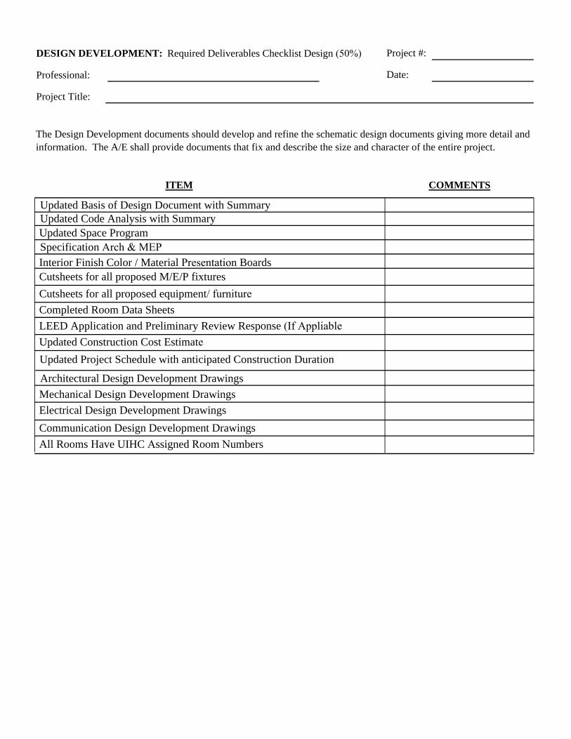
December 15, 2012
Project #:
Date:
DESIGN DEVELOPMENT: Required Deliverables Checklist Design (50%)
Professional:
Project Title:
LEED Application and Preliminary Review Response (If Appliable
All Rooms Have UIHC Assigned Room Numbers
Architectural Design Development DrawingsMechanical Design Development DrawingsElectrical Design Development DrawingsCommunication Design Development Drawings
Interior Finish Color / Material Presentation Boards
Updated Project Schedule with anticipated Construction Duration
Updated Basis of Design Document with Summary
Updated Space ProgramUpdated Code Analysis with Summary
COMMENTS
The Design Development documents should develop and refine the schematic design documents giving more detail and information. The A/E shall provide documents that fix and describe the size and character of the entire project.
ITEM
Updated Construction Cost Estimate
Cutsheets for all proposed equipment/ furnitureCutsheets for all proposed M/E/P fixtures
Specification Arch & MEP
Completed Room Data Sheets
November 1, 2016
Appendix C
Construction Documents: Required Deliverables Checklist
November 1, 2016
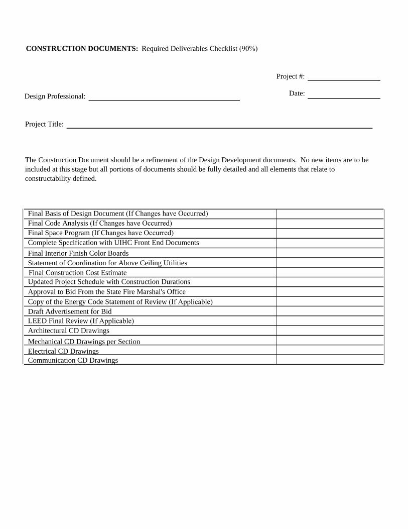
Project #:
Date:
LEED Final Review (If Applicable)
Communication CD Drawings
Architectural CD DrawingsMechanical CD Drawings per SectionElectrical CD Drawings
Complete Specification with UIHC Front End Documents
Approval to Bid From the State Fire Marshal's Office
CONSTRUCTION DOCUMENTS: Required Deliverables Checklist (90%)
Design Professional:
Project Title:
Copy of the Energy Code Statement of Review (If Applicable)
Final Space Program (If Changes have Occurred)
The Construction Document should be a refinement of the Design Development documents. No new items are to be included at this stage but all portions of documents should be fully detailed and all elements that relate to constructability defined.
Final Code Analysis (If Changes have Occurred)
Draft Advertisement for Bid
Final Interior Finish Color BoardsStatement of Coordination for Above Ceiling UtilitiesFinal Construction Cost EstimateUpdated Project Schedule with Construction Durations
Final Basis of Design Document (If Changes have Occurred)
August 1, 2016
Appendix D
UIHC Preferred Products for Electro/Mechanical Systems
November 1, 2016
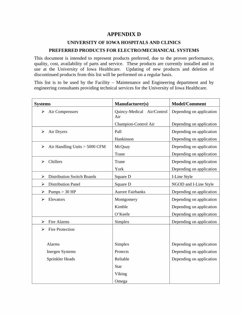
APPENDIX D UNIVERSITY OF IOWA HOSPITALS AND CLINICS
PREFERRED PRODUCTS FOR ELECTRO/MECHANICAL SYSTEMS This document is intended to represent products preferred, due to the proven performance, quality, cost, availability of parts and service. These products are currently installed and in use at the University of Iowa Healthcare. Updating of new products and deletion of discontinued products from this list will be performed on a regular basis.
This list is to be used by the Facility – Maintenance and Engineering department and by engineering consultants providing technical services for the University of Iowa Healthcare.
Systems Manufacturer(s) Model/CommentAir Compressors Quincy-Medical Air/Control
Air
Champion-Control Air
Depending on application
Depending on application
Air Dryers Pall
Hankinson
Depending on application
Depending on application
Air Handling Units > 5000 CFM McQuay
Trane
Depending on application
Depending on application
Chillers Trane
York
Depending on application
Depending on application
Distribution Switch Boards Square D I-Line Style
Distribution Panel Square D NGOD and I-Line Style
Pumps > 30 HP Aurore Fairbanks Depending on application
Elevators Montgomery
Kimble
O’Keefe
Depending on application
Depending on application
Depending on application
Fire Alarms Simplex Depending on application
Fire Protection
Alarms
Inergen Systems
Sprinkler Heads
Simplex
Protects
Reliable
Star
Viking
Omega
Depending on application
Depending on application
Depending on application
November 1, 2016
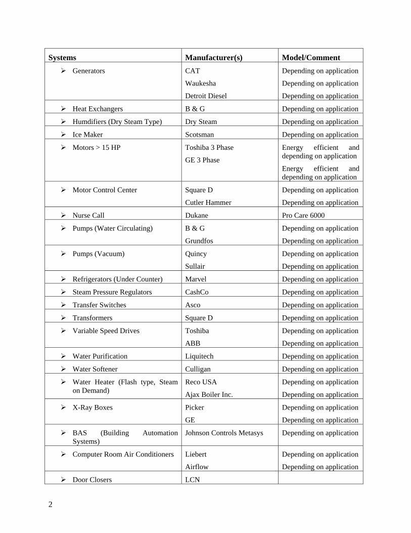
Systems Manufacturer(s) Model/CommentGenerators CAT
Waukesha
Detroit Diesel
Depending on application
Depending on application
Depending on application
Heat Exchangers B & G Depending on application
Humdifiers (Dry Steam Type) Dry Steam Depending on application
Ice Maker Scotsman Depending on application
Motors > 15 HP Toshiba 3 Phase
GE 3 Phase
Energy efficient and depending on application
Energy efficient and depending on application
Motor Control Center Square D
Cutler Hammer
Depending on application
Depending on application
Nurse Call Dukane Pro Care 6000
Pumps (Water Circulating) B & G
Grundfos
Depending on application
Depending on application
Pumps (Vacuum) Quincy
Sullair
Depending on application
Depending on application
Refrigerators (Under Counter) Marvel Depending on application
Steam Pressure Regulators CashCo Depending on application
Transfer Switches Asco Depending on application
Transformers Square D Depending on application
Variable Speed Drives Toshiba
ABB
Depending on application
Depending on application
Water Purification Liquitech Depending on application
Water Softener Culligan Depending on application
Water Heater (Flash type, Steamon Demand)
Reco USA
Ajax Boiler Inc.
Depending on application
Depending on application
X-Ray Boxes Picker
GE
Depending on application
Depending on application
BAS (Building Automation Systems)
Johnson Controls Metasys Depending on application
Computer Room Air Conditioners Liebert
Airflow
Depending on application
Depending on application
Door Closers LCN
2
November 1, 2016
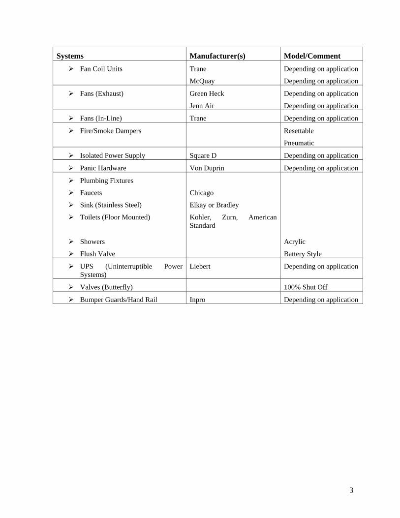
Systems Manufacturer(s) Model/CommentFan Coil Units Trane
McQuay
Depending on application
Depending on application
Fans (Exhaust) Green Heck
Jenn Air
Depending on application
Depending on application
Fans (In-Line) Trane Depending on application
Fire/Smoke Dampers Resettable
Pneumatic
Isolated Power Supply Square D Depending on application
Panic Hardware Von Duprin Depending on application
Plumbing Fixtures
Faucets
Sink (Stainless Steel)
Toilets (Floor Mounted)
Showers
Flush Valve
Chicago
Elkay or Bradley
Kohler, Zurn, American Standard
Acrylic
Battery Style
UPS (Uninterruptible Power Systems)
Liebert Depending on application
Valves (Butterfly) 100% Shut Off
Bumper Guards/Hand Rail Inpro Depending on application
3
November 1, 2016
Appendix E
Division 27: Communications

HEALTHCARE INFORMATION SYSTEMS TECHNOLOGY DESIGN GUIDELINES October 31, 2017
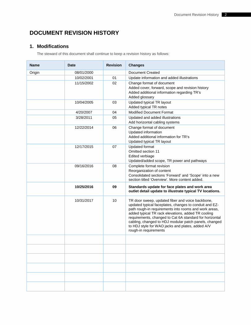
2 Document Revision History
DOCUMENT REVISION HISTORY
1. Modifications The steward of this document shall continue to keep a revision history as follows:
Name Date Revision Changes
Origin 08/01/2000 Document Created 10/02/2001 01 Update information and added illustrations 11/15/2002 02 Change format of document
Added cover, forward, scope and revision history Added additional information regarding TR’s Added glossary
10/04/2005 03 Updated typical TR layout Added typical TR notes
4/20/2007 04 Modified Document Format 3/28/2011 05 Updated and added illustrations
Add horizontal cabling systems 12/22/2014 06 Change format of document
Updated information Added additional information for TR’s Updated typical TR layout
12/17/2015 07 Updated format Omitted section 11 Edited verbiage Updated/added scope, TR power and pathways
09/16/2016 08 Complete format revision Reorganization of content Consolidated sections ‘Forward’ and ‘Scope’ into a new section titled ‘Overview’. More content added.
10/25/2016 09 Standards update for face plates and work area outlet detail update to illustrate typical TV locations.
10/31/2017 10 TR door sweep, updated fiber and voice backbone, updated typical faceplates, changes to conduit and EZ-path rough-in requirements into rooms and work areas, added typical TR rack elevations, added TR cooling requirements, changed to Cat 6A standard for horizontal cabling, changed to HDJ modular patch panels, changed to HDJ style for WAO jacks and plates, added A/V rough-in requirements
3 Table of Contents
Table of Contents Document Revision History ............................................................................................................................................ 2
1. Modifications ..................................................................................................................................................... 2 Table of Contents ........................................................................................................................................................... 3 Overview ........................................................................................................................................................................ 4
1. Purpose ............................................................................................................................................................. 4 2. Referenced Standards, Codes and Additional Guidelines ................................................................................ 4 3. Document Maintenance .................................................................................................................................... 5 4. Consultant Deliverables .................................................................................................................................... 5 5. Departmental Contact Information .................................................................................................................... 5 6. Escalation Procedures ...................................................................................................................................... 5
Glossary of Terms .......................................................................................................................................................... 6 1. Key Terms ......................................................................................................................................................... 6 2. Acronyms .......................................................................................................................................................... 7
Telecommunications Design .......................................................................................................................................... 9 1. Space Design: Telecommunications Room (TR) .............................................................................................. 9 2. System Design: Horizontal Pathway System and Rough-in Requirements..................................................... 16 3. System Design: Backbone Pathway Requirements ........................................................................................ 18 4. System Design: Backbone Distribution System .............................................................................................. 18 5. System Design: Horizontal Cabling Systems .................................................................................................. 19 6. Close-out Process and Expected Deliverables ............................................................................................... 20
Nurse Call Design ........................................................................................................................................................ 21 1. Design Requirements Overview ...................................................................................................................... 21
Appendix A ................................................................................................................................................................... 22 1. Approved Manufacturers and Products ........................................................................................................... 22 2. Illustrations: Example Telecommunications Room (TR).................................................................................. 24 3. Illustrations: Typical Details ............................................................................................................................. 28
TABLE OF CONTENTS
4 Overview
OVERVIEW
1. Purpose This document has been prepared in order to educate and assist those in a design role for the University of Iowa Hospitals and Clinics. The goal is to adequately serve and support patient care systems installed throughout our facilities utilizing this as the published standard. This document is not intended to be exhaustive however it shall be considered authoritative in all areas that it addresses. These standards shall be applied to all renovations and new construction projects as it relates to technology design.
The term ‘telecommunications’, as used in this guideline, shall refer to the transmission of all forms of information (e.g., voice, data, video, security, audio, industrial, building control). Telecommunications equipment used to support these wide varieties of systems rely on effective building infrastructure. This infrastructure encompasses spaces, pathways, cables, connecting hardware, and a high quality bonding and grounding system.
It is expected that this document shall be primarily used by architects, engineers, and planners.
2. Referenced Standards, Codes and Additional Guidelines These guidelines are based on a combination of preferred methods by the Hospital in addition to well-known published standards, codes and guidelines.
• Building Industry Consultant Services International (BICSI) o Telecommunications Distribution Methods Manual (TDMM) o Data Center Design and Implantation Best Practices ANSI/BICSI 002-2014
• Electronics Industry Association/Telecommunications Industry Association (EIA/TIA) o Commercial Building Telecommunications Infrastructure Standard - TIA-568 o Telecommunications Pathways and Spaces - TIA-569 o Administration Standard for Telecommunications Infrastructure - TIA-606 o Telecommunications Bonding and Grounding - TIA-607 o Telecommunications Infrastructure Standard for Data Centers - TIA-942 o Healthcare Facility Telecommunications Infrastructure Standard – TIA-1179
• National Fire Protection Association (NFPA) o National Electric Code - NFPA 70 o National Fire Alarm and Signaling Code - NFPA 72 o Health Care Facilities Code – NFPA 99 o National Life Safety Code - NFPA 101
• Underwriter’s Laboratories (UL) o Standards for Hospital Signaling and Nurse Call Equipment – UL 1069
• Joint Commission on Accreditation of Healthcare Organizations (JCAHO) • Americans with Disabilities Act Accessibility Guidelines (ADAAG)
The purpose of a standard is to ensure a minimum level of performance. Codes often reference numerous safety standards to assure the minimum safety requirements of a given material or components are met. It is the intent that there shall be no published design guideline herein that shall conflict with life safety requirements.
5 Overview
3. Document Maintenance Modifications and additions to this document shall be managed by TJ Ramsey and Brad Henderson.
4. Consultant Deliverables All construction documents including but not limited to: drawings, details, schedules, legends and specifications shall be in alignment with the standards and guidelines defined herein. Any deviations from these standards shall require written authorization from the Healthcare Information Systems department.
During each milestone of design, the Healthcare Information Systems representative shall perform a project review. Comments will be delivered to the technology design consultant and will require follow up to ensure any and all conflicts, issues and/or questions are answered and rectified.
5. Departmental Contact Information
Name Department Systems Tele.#
TJ Ramsey Healthcare Information Systems UIHC Telecommunications 319-325-3790
Brad Henderson Healthcare Information Systems UIHC Telecommunications 319-356-2128
Jody Reinier Healthcare Information Systems UIHC Audio Visual Systems 319-384-6310
Scott Spinler Healthcare Information Systems UIHC Nurse Call 319-356-2123
Bill Hoffman Safety and Security UIHC Fire Detection and Alarm 319-356-7150
George Stumpf ITS Enterprise Infrastructure U of I Telecommunications 319-335-2814
6. Escalation Procedures In the event of design questions, issues or conflicts please contact TJ Ramsey at the telephone number shared above to start the escalation process.
6 Glossary of Terms
GLOSSARY OF TERMS
1. Key Terms
BACKBONE – A facility (pathway, cable, or conductors) between telecommunications rooms, or floor distribution terminals, the entrance facilities, and the equipment rooms within or between buildings.
BACKBONE CABLING – Cable and connecting hardware that provides interconnections between telecommunications rooms, equipment rooms, and entrance facilities.
BACKBONE PATHWAY – The portion of the pathway system that permits the placing of backbone cables between the entrance location and all cross-connect points within a building and between buildings.
BEND RADIUS – Maximum radius that a cable can be bent to avoid physical or electrical damage or cause adverse transmission performance.
BONDING – The permanent joining of metallic parts to form an electrically conductive path that will assure electrical continuity, the capacity to safely conduct any current likely to be imposed, and the ability to limit differences in potentials between the joined parts.
CABLE TRAY – A support mechanism used to route and support telecommunications cable. These are typically equipped with sides that allow cables to be placed within the sides over its entire length.
CABLING – A combination of all copper and optical fiber telecommunications cables, equipment patch cords, and connect hardware.
CEILING DISTRIBUTION SYSTEM – A distribution system that uses the space between a suspended, or false ceiling and the structural surface above the ceiling.
CODE – A systematic collection of regulations and rules intended to ensure safety during installation and use of materials, components, fixtures, systems, premises, and related subjects. Codes are typically invoked and enforced through government regulation.
CONDUIT – A rigid or flexible metallic or non-metallic raceway of circular cross-section through which cables can be pulled.
CONNECTING HARDWARE – A device, or combination of devices, used to connect two cables or cable elements.
CROSS-CONNECTION – A connection scheme between cabling runs, subsystems, and equipment using patch cords or jumpers that attach to connection hardware on each end.
ELECTROMAGNETIC INTERFERENCE (EMI) – Any electrical, or electromagnetic interference that causes undesirable signals on a device, equipment, or system.
GROUND – A reference point in an electrical circuit from which voltages are measured, a common return path for electric current, or a direct physical connection to the earth.
GROUNDING BUS BAR – A suitable bar, bus, terminal strip, or binding post terminal where grounding and bonding conductors can be connected.
HORIZONTAL CABLING – The cabling between and including the work area telecommunications outlet/connector and the floor distributor in the telecommunications room.
7 Glossary of Terms
INFRASTRUCTURE – Permanently installed cable plant.
J-HOOK – A supporting device for horizontal cables that is shaped like a ‘J’. It is typically attached above an accessible ceiling space, or on to the building structure to manage special systems cabling.
LADDER RACK – A device similar to a cable tray but more closely resembles a single section of a ladder.
MEDIA – Wire, cable, or conductors used for telecommunications.
MODULAR JACK – A female telecommunications connector typically found at the work area outlet.
PATCH CORD – A length of cable with connectors on one or both ends used to join telecommunications circuits/links at the cross-connect.
PHYSICAL TOPOLOGY – The physical layout of a network as defined by its cabling architecture.
PULL STRING – String placed within a cable pathway, used to pull wire and cable.
SLEEVE – A short section of conduit, either metallic or non-metallic, lining an opening in the wall or floor for cables to pass through.
STANDARD – A collection of requirements that encompasses properties of components and systems that are intended to ensure an accepted degree of functionality and longevity.
TELECOMMUNICATIONS – A branch of technology concerned with the transmission, and reception of signs, signals, writing, images, and sounds or intelligence of any nature by wire, radio, optical, or other electromagnetic systems.
TELECOMMUNICATIONS ROOM (TR) – An enclosed space for housing telecommunications equipment, cable terminations, and cross-connects. The room is the recognized cross-connect between the backbone cable and horizontal cabling.
WORK AREA – A building space where the occupants interact with telecommunications terminal equipment.
WORK AREA OUTLET – A device placed at a user workstation for termination of horizontal media and for connectivity of network equipment.
2. Acronyms AHJ – Authority Having Jurisdiction
AWG – American Wire Gauge
BICSI – Building Industry Consulting Services International
BCT – Bonding Conductor for Telecommunications
BD – Building Distributor
DMARC – The demarcation point in which the local carriers cabling and/or equipment terminates. Also the point in which the cabling transitions from “utility-owned” to “building-owned”.
DPS – Door Position Switch
EF – Entrance Facility
EM – Emergency Power

8 Glossary of Terms
ER – Equipment Room
HCIS – Healthcare Information Services
HVAC – Heating Ventilation Air Conditioning
IDF – Intermediate Distribution Frame
IT – Information Technology
JCAHO – Joint Commission on Accreditation of Healthcare Organizations
MC – Main Cross Connect Room
MDF – Main Distribution Frame
NEC – National Electric Code
NEMA – National Electrical Manufacturers Association
NFPA – National Fire Protection Association
REX – Request to Exit
TDMM – Telecommunications Distribution Methods Manual
TMGB – Telecommunications Main Ground Bus Bar
TR – Telecommunications Room
UL – Underwriter’s Laboratories
UPS – Uninterruptable Power Supply
UTP – Unshielded Twisted Pair
VCT – Vinyl Composite Tile
VoIP – Voice over Internet Protocol
WAO – Work area outlet
9 Telecommunications Design
TELECOMMUNICATIONS DESIGN
3. Space Design: Telecommunications Room (TR) Telecommunications Rooms are generally considered to be floor-serving spaces that provide a connection point between backbone and horizontal infrastructures. Telecommunication Rooms shall provide an environmentally suitable and secure area for installing communication cables, cross-connect fields, relay racks, wall-mounted hardware, and active telecommunications electronic equipment.
Due to increased demand for desktop automation, voice and data integration, desk-to-desk information exchange, and integration of other building systems into the structured cabling system, a dedicated Telecommunications Room (TR) is necessary.
ARCHITECTURAL REQUIREMENTS:
A. Location 1. In order to minimize the horizontal cable lengths, locate the TR as close as possible to the center
of, the area it is intended to serve. 2. The furthest area served with telecommunications cabling shall not exceed 295 feet (90m). 3. There shall be at least one TR per floor. TR’s in a multi-floor building shall be stacked vertically. 4. There shall be a minimum of one TR per 10,000 square feet of office, clinic, and inpatient units
served. If the area served by a TR is larger than 10,000 square feet, the TR shall be increased in size as necessary.
5. Locate TRs away from mechanical chases to avoid pathway congestion. 6. Rooms shall not be placed directly under bathrooms, kitchens or other water sources. 7. Each TR shall have uninterrupted access that does not interfere with normal business activities.
Access to the room shall be direct from corridors and shall not be via conference rooms, break room areas, etc.
B. Size 1. Each newly constructed TR shall be a minimum of 10’ by 20’ with continuous floor space serving a
maximum area of 20,000 square feet. The TR square footage is to be 1/100 the size of the total square footage of the area it is intended to serve. In some instances, the TR may be larger in order to serve the intended area, up to 25,000 square feet. Consult HCIS on sizing of rooms serving areas larger than 20,000 square feet.
C. Accessibility 1. TR doors shall always swing outside of the room and into a common corridor so that valuable wall
space can be utilized to mount special systems. 2. Doors shall be fully opening (180 degrees), lockable, equipped with card access and meet ADA
requirements.
D. Ceiling Height 1. The minimum ceiling height should be 8.5 feet above finished floor. Consideration should be given
to having a 10-foot height. 2. To permit maximum flexibility and accessibility of cabling pathways, suspended ceilings shall not be
permitted in TR’s. 3. When a ceiling distribution system is used, design TRs with adequate pathways or openings
through beams and other obstructions into the accessible ceiling space. 4. The ceiling finish should minimize dust and be light colored to enhance the room lighting.
10 Telecommunications Design
E. Wall Construction, Floor Covering, and Room Finishes 1. To avoid dust and static electricity the TR floor shall be treated with sheet vinyl, off white, or VCT. 2. All walls shall be constructed to the deck and sealed air tight to minimize dust. 3. Door shall be equipped with a dust sweep to minimize dust entering the TR space. The dust sweep
shall be installed on the inside of the room. http://straughanhardwareonlinestore.miiduu.com/reese-enterprise-967c-36-brush-sweep
4. The desire is that all walls hosting EZ-Path fire rated sleeves shall host the entire bank of sleeves inside the same wall cavity. This may require special framing accommodations in order to accomplish. See the typical telecommunications room floor plan detail in the Appendix for an illustration of these sleeves.
5. All walls shall be finished and painted from the finished floor to and including decking above with Sherwin Williams #B49 W2 paint.
6. All walls shall be lined with plywood and mounted at a minimum height of 6” above finished floor. See fire protection engineering requirements below for additional information.
ENGINEERING REQUIREMENTS:
A. Environmental Controls 1. Maintain continuous and dedicated environmental control 24 hours per day, 365 days per year. 2. Design consultant shall calculate the heat load by using equipment manufacturer’s specifications
for each component. Allow for 50 percent growth. 3. A thermostat shall be located within the TR and control the TR only. 4. Maintain a temperature in the following range: 64 degrees F to 75 degrees F. 5. The acceptable relative humidity range should be 30% - 55%. 6. Dissipate the heat generated by active devices. 7. Temperature shall not increase 10 degrees in 60 minutes. 8. Maintain positive pressure with a minimum of one air change per hour. 9. If an independent cooling unit is installed, the unit shall be located outside of the TR. 10. When installed air conditioning units in the rooms, provide drip pans, shields and drains for leakage
and condensation. 11. Units must be on Emergency power. 12. If chilled water solution, chilled water lines must have a filter system and placed in good location to
maintain. 13. See attached specifications for specific requirements. 14. 3 Rack Solution assuming adjacent space has ceiling space available.
a. Option 1 Chilled Water Available i. Provide Liebert 3 Ton Mini Mate Model Number MMD040CPHEDO ii. Contractor to provide duct work. Supply ductwork to the front of the racks and
return duct work to the back of the racks. Ductwork sized for 1,250 CFM. iii. Contractor to provide chilled water piping to accommodate 7.2 GPM iv. Contractor to provide 208 volt Power Connection. v. Units to be provided with Liebert CMS Control.
b. Option 2 If Chilled Water is not available. i. Provide Liebert 2 Ton DX Mini Mate Evaporator Model Number MMD24EPHED0 ii. Provide Liebert 2 Ton Condensing Unit Model Number: PFH027A-PL7, unit to be
located outside on roof or ground level on concrete pad. iii. Contractor to provide duct work. Supply ductwork to the front of the racks and
return duct work to the back of the racks. Ductwork sized for 885 CFM. iv. Contractor to provide 208 volt Power Connection to indoor unit and outdoor unit v. Units to be provided with Liebert CMS Control.
11 Telecommunications Design
vi. Contractor to provide refrigerant piping, refrigerant and all necessary piping connections. Contact Manufacturer for pipe sizing based on distance from indoor unit to outdoor unit.
15. 5 Rack Solution assuming adjacent space has ceiling space available. a. Option 1 Chilled Water Available
i. Provide Liebert 3 Ton Mini Mate Model Number MMD040CPHEDO ii. Contractor to provide duct work. Supply ductwork to the front of the racks and
return duct work to the back of the racks. Ductwork sized for 1,250 CFM. iii. Contractor to provide chilled water piping to accommodate 7.2 GPM iv. Contractor to provide 208 volt Power Connection. v. Units to be provided with Liebert CMS Control.
b. Option 2 If Chilled Water is not available. i. Provide Liebert 3 Ton DX Mini Mate Evaporator Model Number MMD36EPHED0 ii. Provide Liebert 3 Ton Condensing Unit Model Number: PFH037A-PL7, unit to be
located outside on roof or ground level on concrete pad. iii. Contractor to provide duct work. Supply ductwork to the front of the racks and
return duct work to the back of the racks. Ductwork sized for 1,250 CFM. iv. Contractor to provide 208-volt Power Connection to indoor unit and outdoor unit. v. Units to be provided with Liebert CMS Control. vi. Contractor to provide refrigerant piping, refrigerant and all necessary piping
connections. Contact Manufacturer for pipe sizing based on distance from indoor unit to outdoor unit.
16. 3 Rack Solution Wall Mount. a. Option 1 Chilled Water Available
i. Provide Liebert 3 Ton Data Mate Number DME044C-PH7 ii. Mount the unit on the hot aisle of the racks with the top of the cooling units higher
than the top of the racks. iii. Contractor to provide chilled water piping to accommodate 7.3 GPM iv. Contractor to provide 208 volt Power Connection. v. Units to be provided with Liebert CMS Control.
b. Option 2 If Chilled Water is not available. i. Provide Liebert 2 Ton DX Data Mate Evaporator Model Number DME027E-PH7 ii. Provide Liebert 2 Ton Condensing Unit Model Number: PFH027A-PL7, unit to be
located outside on roof or ground level on concrete pad. iii. Mount the unit on the hot aisle of the racks with the top of the cooling units higher
than the top of the racks. iv. Contractor to provide 208 volt Power Connection to indoor unit and outdoor unit v. Units to be provided with Liebert CMS Control. vi. Contractor to provide refrigerant piping, refrigerant and all necessary piping
connections. Contact Manufacturer for pipe sizing based on distance from indoor unit to outdoor unit.
17. 3 Rack Solution Wall Mount. a. Option 1 Chilled Water Available
i. Provide Liebert 3 Ton Data Mate Number DME044C-PH7 ii. Mount the unit on the hot aisle of the racks with the top of the cooling units higher
than the top of the racks. iii. Contractor to provide chilled water piping to accommodate 7.3 GPM iv. Contractor to provide 208 volt Power Connection. v. Units to be provided with Liebert CMS Control.
b. Option 2 If Chilled Water is not available. i. Provide Liebert 3 Ton DX Data Mate Evaporator Model Number DME037E-PH7
12 Telecommunications Design
ii. Provide Liebert 3 Ton Condensing Unit Model Number: PFH037A-PL7, unit to be located outside on roof or ground level on concrete pad.
iii. Mount the unit on the hot aisle of the racks with the top of the cooling units higher than the top of the racks.
iv. Contractor to provide 208 volt Power Connection to indoor unit and outdoor unit v. Units to be provided with Liebert CMS Control. vi. Contractor to provide refrigerant piping, refrigerant and all necessary piping
connections. Contact Manufacturer for pipe sizing based on distance from indoor unit to outdoor unit.
B. Fire Protection 1. Wet sprinklers shall be provided in each TR. Provide a sprinkler zone valve in each room.
a. A single interlock pre-action dry sprinkler system may be necessary if IT equipment value scheduled for the room necessitates it. Inquire with HCIS prior to the design.
2. Provide a cage around each sprinkler head. 3. The room shall be equipped with appropriate fire detection and alarm sensors. 4. All walls inside the TR shall be lined with 4’ x 8’ fire-rated AC-grade or better plywood, 8 feet high
with a minimum thickness of .75”. The “A” side shall be what is exposed with the “C” side facing the wall.
5. Plywood shall be treated on all sides with at least two coats of Sherwin Williams #B49 W2 paint on all sides, leaving a fire-rated stamp visible to meet JCAHO standards.
6. The plywood shall be continuous, into the corners, and mounted with appropriately rated hardware and not standard sheetrock screws.
C. Power 1. Each TR shall be supplied with both Critical and Normal power. 2. Power requirements at the rack(s):
a. UPS Rack(s) i. Provide one (1) dedicated 120VAC quad receptacle and one (1) dedicated
208VAC circuit on emergency generator power. Depending on the UPS scheduled for the rack, the 208VAC circuit may require up to 60 amps. Coordinate this requirement directly with HCIS. Any receptacle shall be mounted at the rear of the rack and attached rigidly to the cable tray above the vertical manager. The UPS circuit may require a hardwired circuit that can be provided at the base of the rack.
b. Non-UPS Rack(s) i. Provide one (1) dedicated 120VAC quad receptacle and one (1) dedicated
208VAC circuit on normal power. Receptacles shall be mounted at the rear of the rack and attached rigidly to the cable tray above the vertical manager.
3. Power distribution for rack mounted equipment shall be done through the use of a monitored horizontal PDU. Provide a single data connection to each individual horizontal PDU scheduled.
4. Wall receptacles: a. Provide 120V-20A receptacles to serve the following:
i. Software House Access Control System – Emergency Power ii. Lencore Sound Masking – Normal Power iii. Distributed Antenna System – Emergency Power iv. Primex Wireless Clock Transmitter – Normal Power
b. Provide 120V-20A circuits to serve the following: i. Rauland Responder 5 Nurse Call – Emergency Power
13 Telecommunications Design
D. Uninterruptable Power Supplies (UPS) 1. At a minimum, a standalone owner provided UPS shall be installed in each TR to support the
installed equipment. A centralized UPS may be considered on a per project basis. 2. Depending on the UPS size, the circuits serving the device shall either be mounted rigidly to the
cable tray or hardwired to the UPS at the base of the rack. Contact HCIS for specific direction. 3. Provide a fire detection and alarm monitor module at the UPS. A supervisory alarm signal shall be
sent when line voltage is removed and UPS is running on battery power. 4. UPS Options that shall be accommodated:
a. Small – APC 3000VA (120V) b. Medium – APC 6000VA (208V – Hardwired) single phase and step down c. Large – APC 10KVA (208V - Hardwired) single phase and step down
5. Coordinate amperage requirements of the hardwired UPS with HCIS.
E. Lighting 1. Provide a minimum of 50 foot candles measured 3 feet above the finished floor in front and back of
installed relay racks. 2. Provide a minimum of two (2) fluorescent or LED strip fixtures on occupancy sensors. At least one
light should be on emergency power.
F. Conduit, Sleeves and Ducts 1. Locate sleeve systems in places where pulling and termination will be organized and accessible for
future use. 2. Where vertical and horizontal offsets are required, consider bend radius requirements and service
loops. 3. In stacked closet locations, install a minimum of three (3) trade size STI series 44 EZ-Path fire-
rated sleeves in the floor to accommodate backbone pathways. Work with HCIS to determine location and quantity. Install per manufacturer guidelines.
4. A minimum of ten (10) trade size STI series 44 EZ-Path fire-rated sleeves shall be provided for horizontal/backbone cabling. They shall be in two groups of five. All sleeves shall terminate at the cable tray within the TR. Location will be determined by HCIS. Depending on the area served, additional sleeves may be necessary. All sleeves must be accessible from both sides.
5. Install one (1) 1” (recessed) EMT conduit and single gang outlet for a wall phone. Phone shall be located just within the entrance of the TR.
G. Racks, Cabinets and Enclosures 1. Racks shall be used to house termination components of the telecommunications cabling
infrastructure. They shall also host data network equipment. 2. TR rack numbering shall start with RR-01 at the wall opposite the TR door entrance. 3. The racks shall be a standard 7’ tall, 2-post with a floor mounted design. Provide with two-sided
EIA hole pattern and 19” wide. 4. A minimum of 3 feet shall be given between rows of racks. 5. Install 12” vertical wire managers between adjoining racks and a 6” cable manager at each end of
the row. The rack closest to the wall shall be given 6” of clearance away from the wall. 6. All racks shall be secured and anchored at the base of the rack. 7. Each rack shall be bonded with a dedicated #6 AWG copper conductor back to the TR’s TGB.
H. Cable Tray
1. Basket style tray shall be provided around the perimeter of the room to serve all horizontal data cabling as well as backbone cabling. See chart below for sizing guidelines.
2. A separate 6” wide x 4” deep cable tray shall be provided and installed above the horizontal data cabling tray to serve access control and special systems cabling.
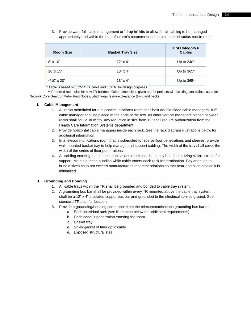
14 Telecommunications Design
3. Provide waterfall cable management or “drop-in” kits to allow for all cabling to be managed appropriately and within the manufacturer’s recommended minimum bend radius requirements.
Room Size Basket Tray Size # of Category 6
Cables
8’ x 10’ 12” x 4” Up to 240*
10’ x 15’ 18” x 4” Up to 365*
**10’ x 20’ 18” x 4” Up to 365*
* Table is based on 0.25” O.D. cable and 50% fill for design purposes ** Preferred room size for new TR buildout. Other dimensions given are for projects with existing constraints, used for Network Core Gear, or Metro Ring Nodes, which require more clearance (front and back).
I. Cable Management 1. All racks scheduled for a telecommunications room shall host double-sided cable managers. A 6”
cable manager shall be placed at the ends of the row. All other vertical managers placed between racks shall be 12” in width. Any reduction in size from 12” shall require authorization from the Health Care Information Systems department.
2. Provide horizontal cable managers inside each rack. See the rack diagram illustrations below for additional information.
3. In a telecommunications room that is scheduled to receive floor penetrations and sleeves, provide wall mounted basket tray to help manage and support cabling. The width of the tray shall cover the width of the series of floor penetrations.
4. All cabling entering the telecommunications room shall be neatly bundled utilizing Velcro straps for support. Maintain these bundles while cable enters each rack for termination. Pay attention to bundle sizes as to not exceed manufacturer’s recommendations so that near-end alien crosstalk is minimized.
J. Grounding and Bonding 1. All cable trays within the TR shall be grounded and bonded to cable tray system. 2. A grounding bus bar shall be provided within every TR mounted above the cable tray system. It
shall be a 12” x 4” insulated copper bus bar and grounded to the electrical service ground. See standard TR plan for location.
3. Provide a grounding/bonding connection from the telecommunications grounding bus bar to: a. Each individual rack (see illustration below for additional requirements) b. Each conduit penetration entering the room c. Basket tray d. Shield/jacket of fiber optic cable e. Exposed structural steel
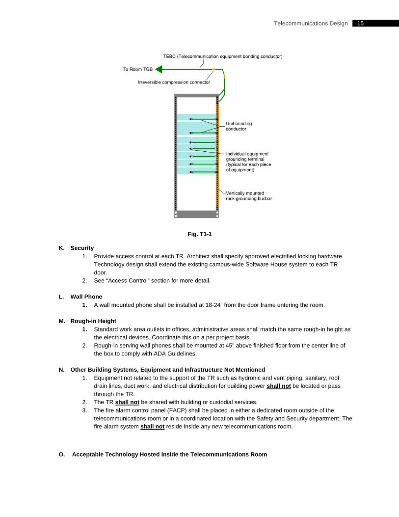
15 Telecommunications Design
Fig. T1-1
K. Security 1. Provide access control at each TR. Architect shall specify approved electrified locking hardware.
Technology design shall extend the existing campus-wide Software House system to each TR door.
2. See “Access Control” section for more detail.
L. Wall Phone 1. A wall mounted phone shall be installed at 18-24” from the door frame entering the room.
M. Rough-in Height
1. Standard work area outlets in offices, administrative areas shall match the same rough-in height as the electrical devices. Coordinate this on a per project basis.
2. Rough-in serving wall phones shall be mounted at 45” above finished floor from the center line of the box to comply with ADA Guidelines.
N. Other Building Systems, Equipment and Infrastructure Not Mentioned 1. Equipment not related to the support of the TR such as hydronic and vent piping, sanitary, roof
drain lines, duct work, and electrical distribution for building power shall not be located or pass through the TR.
2. The TR shall not be shared with building or custodial services. 3. The fire alarm control panel (FACP) shall be placed in either a dedicated room outside of the
telecommunications room or in a coordinated location with the Safety and Security department. The fire alarm system shall not reside inside any new telecommunications room.
O. Acceptable Technology Hosted Inside the Telecommunications Room
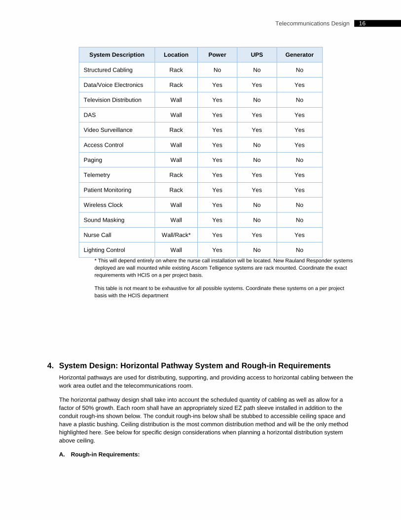
16 Telecommunications Design
System Description Location Power UPS Generator
Structured Cabling Rack No No No
Data/Voice Electronics Rack Yes Yes Yes
Television Distribution Wall Yes No No
DAS Wall Yes Yes Yes
Video Surveillance Rack Yes Yes Yes
Access Control Wall Yes No Yes
Paging Wall Yes No No
Telemetry Rack Yes Yes Yes
Patient Monitoring Rack Yes Yes Yes
Wireless Clock Wall Yes No No
Sound Masking Wall Yes No No
Nurse Call Wall/Rack* Yes Yes Yes
Lighting Control Wall Yes No No
* This will depend entirely on where the nurse call installation will be located. New Rauland Responder systems deployed are wall mounted while existing Ascom Telligence systems are rack mounted. Coordinate the exact requirements with HCIS on a per project basis.
This table is not meant to be exhaustive for all possible systems. Coordinate these systems on a per project basis with the HCIS department
4. System Design: Horizontal Pathway System and Rough-in Requirements Horizontal pathways are used for distributing, supporting, and providing access to horizontal cabling between the work area outlet and the telecommunications room.
The horizontal pathway design shall take into account the scheduled quantity of cabling as well as allow for a factor of 50% growth. Each room shall have an appropriately sized EZ path sleeve installed in addition to the conduit rough-ins shown below. The conduit rough-ins below shall be stubbed to accessible ceiling space and have a plastic bushing. Ceiling distribution is the most common distribution method and will be the only method highlighted here. See below for specific design considerations when planning a horizontal distribution system above ceiling.
A. Rough-in Requirements:
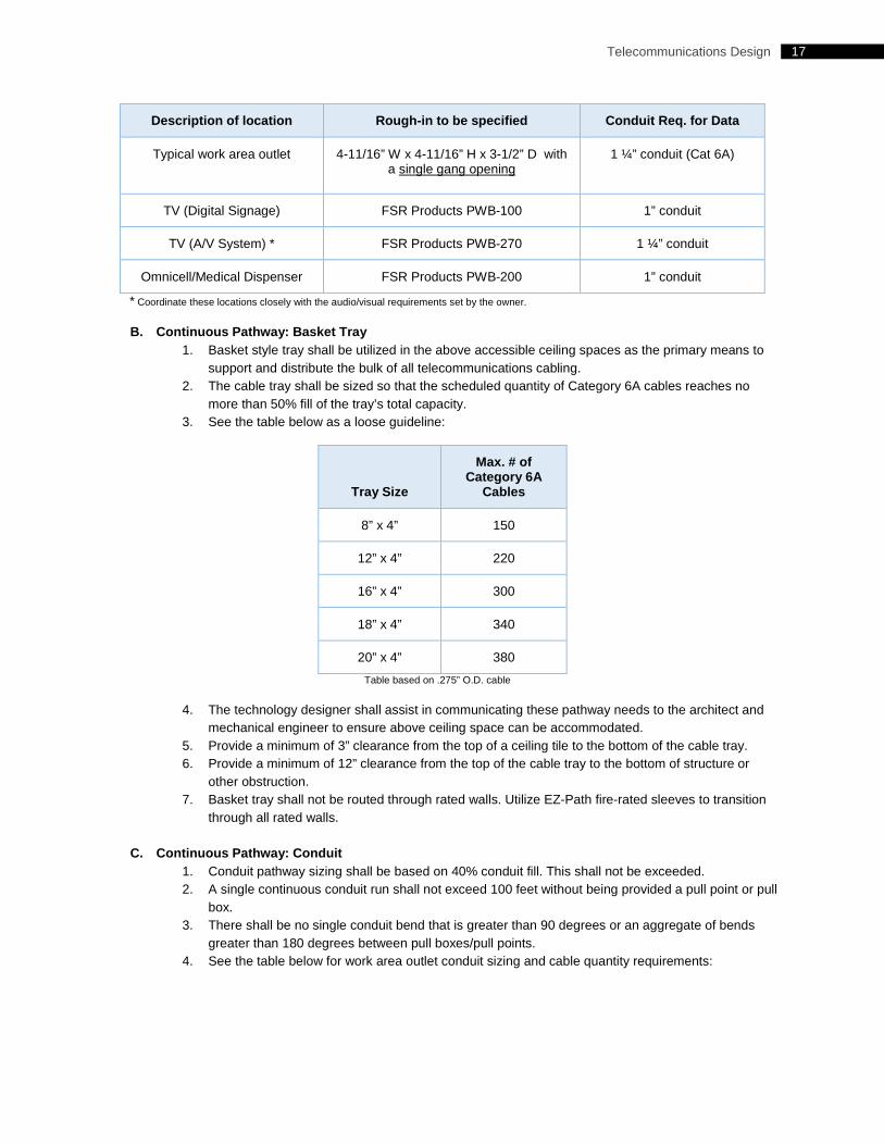
17 Telecommunications Design
Description of location Rough-in to be specified Conduit Req. for Data
Typical work area outlet 4-11/16” W x 4-11/16” H x 3-1/2” D with a single gang opening
1 ¼” conduit (Cat 6A)
TV (Digital Signage) FSR Products PWB-100 1” conduit
TV (A/V System) * FSR Products PWB-270 1 ¼” conduit
Omnicell/Medical Dispenser FSR Products PWB-200 1” conduit
* Coordinate these locations closely with the audio/visual requirements set by the owner.
B. Continuous Pathway: Basket Tray 1. Basket style tray shall be utilized in the above accessible ceiling spaces as the primary means to
support and distribute the bulk of all telecommunications cabling. 2. The cable tray shall be sized so that the scheduled quantity of Category 6A cables reaches no
more than 50% fill of the tray’s total capacity. 3. See the table below as a loose guideline:
Tray Size
Max. # of Category 6A
Cables
8” x 4” 150
12” x 4” 220
16” x 4” 300
18” x 4” 340
20” x 4” 380
Table based on .275” O.D. cable
4. The technology designer shall assist in communicating these pathway needs to the architect and mechanical engineer to ensure above ceiling space can be accommodated.
5. Provide a minimum of 3” clearance from the top of a ceiling tile to the bottom of the cable tray. 6. Provide a minimum of 12” clearance from the top of the cable tray to the bottom of structure or
other obstruction. 7. Basket tray shall not be routed through rated walls. Utilize EZ-Path fire-rated sleeves to transition
through all rated walls.
C. Continuous Pathway: Conduit 1. Conduit pathway sizing shall be based on 40% conduit fill. This shall not be exceeded. 2. A single continuous conduit run shall not exceed 100 feet without being provided a pull point or pull
box. 3. There shall be no single conduit bend that is greater than 90 degrees or an aggregate of bends
greater than 180 degrees between pull boxes/pull points. 4. See the table below for work area outlet conduit sizing and cable quantity requirements:
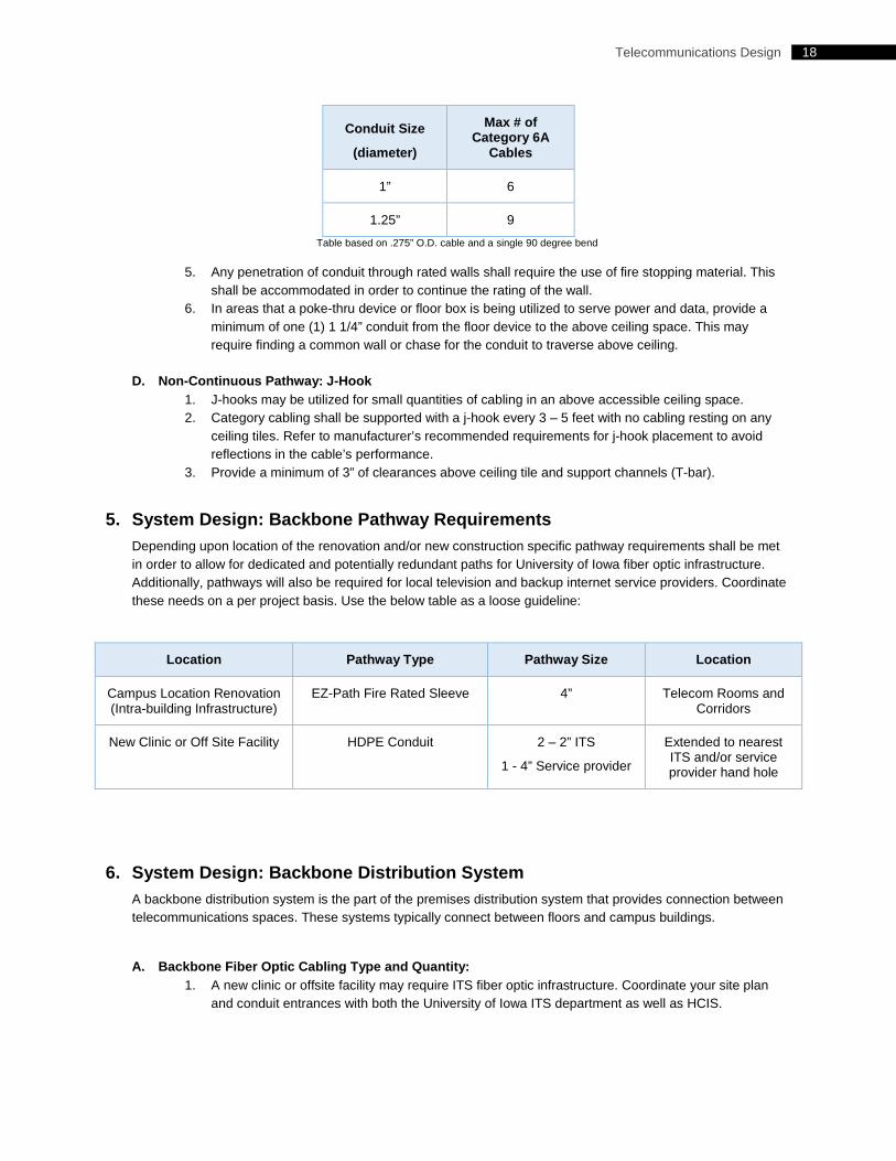
18 Telecommunications Design
Conduit Size
(diameter)
Max # of Category 6A
Cables
1” 6
1.25” 9
Table based on .275” O.D. cable and a single 90 degree bend
5. Any penetration of conduit through rated walls shall require the use of fire stopping material. This shall be accommodated in order to continue the rating of the wall.
6. In areas that a poke-thru device or floor box is being utilized to serve power and data, provide a minimum of one (1) 1 1/4” conduit from the floor device to the above ceiling space. This may require finding a common wall or chase for the conduit to traverse above ceiling.
D. Non-Continuous Pathway: J-Hook 1. J-hooks may be utilized for small quantities of cabling in an above accessible ceiling space. 2. Category cabling shall be supported with a j-hook every 3 – 5 feet with no cabling resting on any
ceiling tiles. Refer to manufacturer’s recommended requirements for j-hook placement to avoid reflections in the cable’s performance.
3. Provide a minimum of 3” of clearances above ceiling tile and support channels (T-bar).
5. System Design: Backbone Pathway Requirements Depending upon location of the renovation and/or new construction specific pathway requirements shall be met in order to allow for dedicated and potentially redundant paths for University of Iowa fiber optic infrastructure. Additionally, pathways will also be required for local television and backup internet service providers. Coordinate these needs on a per project basis. Use the below table as a loose guideline:
Location Pathway Type Pathway Size Location
Campus Location Renovation (Intra-building Infrastructure)
EZ-Path Fire Rated Sleeve 4” Telecom Rooms and Corridors
New Clinic or Off Site Facility HDPE Conduit 2 – 2” ITS
1 - 4” Service provider
Extended to nearest ITS and/or service provider hand hole
6. System Design: Backbone Distribution System A backbone distribution system is the part of the premises distribution system that provides connection between telecommunications spaces. These systems typically connect between floors and campus buildings.
A. Backbone Fiber Optic Cabling Type and Quantity: 1. A new clinic or offsite facility may require ITS fiber optic infrastructure. Coordinate your site plan
and conduit entrances with both the University of Iowa ITS department as well as HCIS.
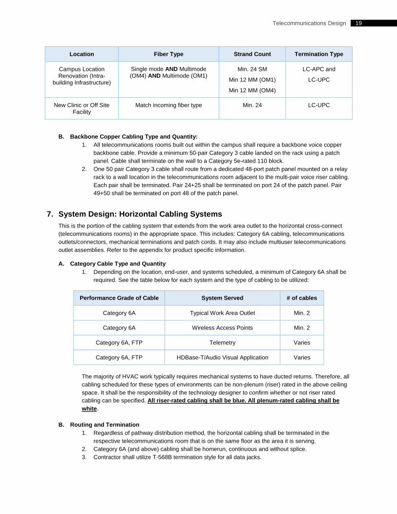
19 Telecommunications Design
Location Fiber Type Strand Count Termination Type
Campus Location Renovation (Intra-
building Infrastructure)
Single mode AND Multimode (OM4) AND Multimode (OM1)
Min. 24 SM
Min 12 MM (OM1)
Min 12 MM (OM4)
LC-APC and
LC-UPC
New Clinic or Off Site Facility
Match incoming fiber type Min. 24 LC-UPC
B. Backbone Copper Cabling Type and Quantity: 1. All telecommunications rooms built out within the campus shall require a backbone voice copper
backbone cable. Provide a minimum 50-pair Category 3 cable landed on the rack using a patch panel. Cable shall terminate on the wall to a Category 5e-rated 110 block.
2. One 50 pair Category 3 cable shall route from a dedicated 48-port patch panel mounted on a relay rack to a wall location in the telecommunications room adjacent to the multi-pair voice riser cabling. Each pair shall be terminated. Pair 24+25 shall be terminated on port 24 of the patch panel. Pair 49+50 shall be terminated on port 48 of the patch panel.
7. System Design: Horizontal Cabling Systems This is the portion of the cabling system that extends from the work area outlet to the horizontal cross-connect (telecommunications rooms) in the appropriate space. This includes: Category 6A cabling, telecommunications outlets/connectors, mechanical terminations and patch cords. It may also include multiuser telecommunications outlet assemblies. Refer to the appendix for product specific information.
A. Category Cable Type and Quantity 1. Depending on the location, end-user, and systems scheduled, a minimum of Category 6A shall be
required. See the table below for each system and the type of cabling to be utilized:
Performance Grade of Cable System Served # of cables
Category 6A Typical Work Area Outlet Min. 2
Category 6A Wireless Access Points Min. 2
Category 6A, FTP Telemetry Varies
Category 6A, FTP HDBase-T/Audio Visual Application Varies
The majority of HVAC work typically requires mechanical systems to have ducted returns. Therefore, all cabling scheduled for these types of environments can be non-plenum (riser) rated in the above ceiling space. It shall be the responsibility of the technology designer to confirm whether or not riser rated cabling can be specified. All riser-rated cabling shall be blue. All plenum-rated cabling shall be white.
B. Routing and Termination 1. Regardless of pathway distribution method, the horizontal cabling shall be terminated in the
respective telecommunications room that is on the same floor as the area it is serving. 2. Category 6A (and above) cabling shall be homerun, continuous and without splice. 3. Contractor shall utilize T-568B termination style for all data jacks.
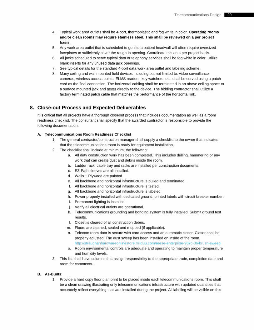
20 Telecommunications Design
4. Typical work area outlets shall be 4-port, thermoplastic and fog white in color. Operating rooms and/or clean rooms may require stainless steel. This shall be reviewed on a per project basis.
5. Any work area outlet that is scheduled to go into a patient headwall will often require oversized faceplates to sufficiently cover the rough-in opening. Coordinate this on a per project basis.
6. All jacks scheduled to serve typical data or telephony services shall be fog white in color. Utilize blank inserts for any unused data jack openings.
7. See typical details for the standard 4-port data work area outlet and labeling scheme. 8. Many ceiling and wall mounted field devices including but not limited to: video surveillance
cameras, wireless access points, ELMS readers, key watchers, etc. shall be served using a patch cord as the final connection. The horizontal cabling shall be terminated in an above ceiling space to a surface mounted jack and never directly to the device. The bidding contractor shall utilize a factory terminated patch cable that matches the performance of the horizontal link.
8. Close-out Process and Expected Deliverables It is critical that all projects have a thorough closeout process that includes documentation as well as a room readiness checklist. The consultant shall specify that the awarded contractor is responsible to provide the following documentation:
A. Telecommunications Room Readiness Checklist 1. The general contractor/construction manager shall supply a checklist to the owner that indicates
that the telecommunications room is ready for equipment installation. 2. The checklist shall include at minimum, the following:
a. All dirty construction work has been completed. This includes drilling, hammering or any work that can create dust and debris inside the room.
b. Ladder rack, cable tray and racks are installed per construction documents. c. EZ-Path sleeves are all installed. d. Walls + Plywood are painted. e. All backbone and horizontal infrastructure is pulled and terminated. f. All backbone and horizontal infrastructure is tested.
g. All backbone and horizontal infrastructure is labeled. h. Power properly installed with dedicated ground, printed labels with circuit breaker number. i. Permanent lighting is installed. j. Verify all electrical outlets are operational.
k. Telecommunications grounding and bonding system is fully installed. Submit ground test results.
l. Closet is cleared of all construction debris. m. Floors are cleaned, sealed and mopped (if applicable). n. Telecom room door is secure with card access and an automatic closer. Closer shall be
properly adjusted. The dust sweep has been installed on inside of the room. http://straughanhardwareonlinestore.miiduu.com/reese-enterprise-967c-36-brush-sweep
o. Room environmental controls are adequate and operating to maintain proper temperature and humidity levels.
3. This list shall have columns that assign responsibility to the appropriate trade, completion date and room for comments.
B. As-Builts: 1. Provide a hard copy floor plan print to be placed inside each telecommunications room. This shall
be a clean drawing illustrating only telecommunications infrastructure with updated quantities that accurately reflect everything that was installed during the project. All labeling will be visible on this
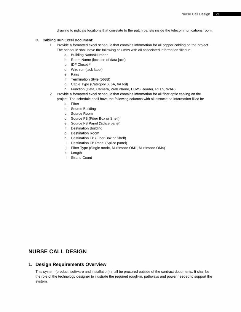
21 Nurse Call Design
drawing to indicate locations that correlate to the patch panels inside the telecommunications room.
C. Cabling Run Excel Document: 1. Provide a formatted excel schedule that contains information for all copper cabling on the project.
The schedule shall have the following columns with all associated information filled in: a. Building Name/Number b. Room Name (location of data jack) c. IDF Closet # d. Wire run (jack label) e. Pairs f. Termination Style (568B)
g. Cable Type (Category 6, 6A, 6A foil) h. Function (Data, Camera, Wall Phone, ELMS Reader, RTLS, WAP)
2. Provide a formatted excel schedule that contains information for all fiber optic cabling on the project. The schedule shall have the following columns with all associated information filled in:
a. Fiber b. Source Building c. Source Room d. Source FB (Fiber Box or Shelf) e. Source FB Panel (Splice panel) f. Destination Building
g. Destination Room h. Destination FB (Fiber Box or Shelf) i. Destination FB Panel (Splice panel) j. Fiber Type (Single mode, Multimode OM1, Multimode OM4)
k. Length l. Strand Count
NURSE CALL DESIGN
1. Design Requirements Overview This system (product, software and installation) shall be procured outside of the contract documents. It shall be the role of the technology designer to illustrate the required rough-in, pathways and power needed to support the system.
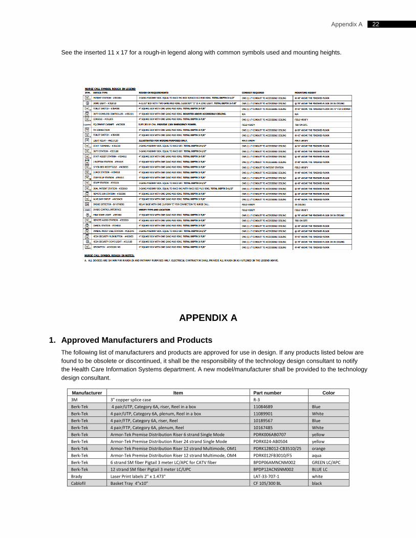
22 Appendix A
See the inserted 11 x 17 for a rough-in legend along with common symbols used and mounting heights.
APPENDIX A
1. Approved Manufacturers and Products The following list of manufacturers and products are approved for use in design. If any products listed below are found to be obsolete or discontinued, it shall be the responsibility of the technology design consultant to notify the Health Care Information Systems department. A new model/manufacturer shall be provided to the technology design consultant.
Manufacturer Item Part number Color 3M 3" copper splice case R-3 Berk-Tek 4 pair/UTP, Category 6A, riser, Reel in a box 11084689 Blue Berk-Tek 4 pair/UTP, Category 6A, plenum, Reel in a box 11089901 White Berk-Tek 4 pair/FTP, Category 6A, riser, Reel 10189567 Blue Berk-Tek 4 pair/FTP, Category 6A, plenum, Reel 10167485 White Berk-Tek Armor-Tek Premise Distribution Riser 6 strand Single Mode PDRK006AB0707 yellow Berk-Tek Armor-Tek Premise Distribution Riser 24 strand Single Mode PDRK024-AB0504 yellow Berk-Tek Armor-Tek Premise Distribution Riser 12 strand Multimode, OM1 PDRK12B012-CB3510/25 orange Berk-Tek Armor-Tek Premise Distribution Riser 12 strand Multimode, OM4 PDRK012FB3010/F5 aqua Berk-Tek 6 strand SM fiber Pigtail 3 meter LC/APC for CATV fiber BPDP06AMNCNM002 GREEN LC/APC Berk-Tek 12 strand SM fiber Pigtail 3 meter LC/UPC BPDP12ACNSNM002 BLUE LC Brady Laser Print labels 2" x 1.473" LAT-33-707-1 white Cablofil Basket Tray 4"x10" CF 105/300 BL black
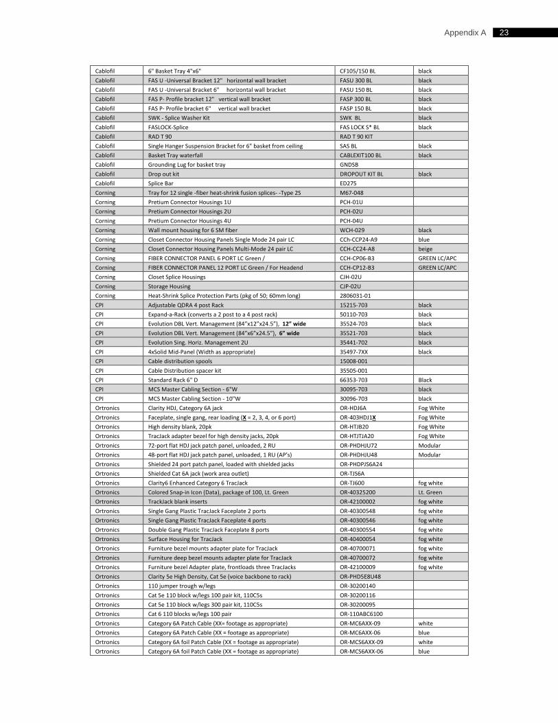
23 Appendix A
Cablofil 6" Basket Tray 4"x6" CF105/150 BL black Cablofil FAS U -Universal Bracket 12" horizontal wall bracket FASU 300 BL black Cablofil FAS U -Universal Bracket 6" horizontal wall bracket FASU 150 BL black Cablofil FAS P- Profile bracket 12" vertical wall bracket FASP 300 BL black Cablofil FAS P- Profile bracket 6" vertical wall bracket FASP 150 BL black Cablofil SWK - Splice Washer Kit SWK BL black Cablofil FASLOCK-Splice FAS LOCK S* BL black Cablofil RAD T 90 RAD T 90 KIT Cablofil Single Hanger Suspension Bracket for 6" basket from ceiling SAS BL black Cablofil Basket Tray waterfall CABLEXIT100 BL black Cablofil Grounding Lug for basket tray GNDSB Cablofil Drop out kit DROPOUT KIT BL black Cablofil Splice Bar ED275 Corning Tray for 12 single -fiber heat-shrink fusion splices- -Type 2S M67-048 Corning Pretium Connector Housings 1U PCH-01U Corning Pretium Connector Housings 2U PCH-02U Corning Pretium Connector Housings 4U PCH-04U Corning Wall mount housing for 6 SM fiber WCH-029 black Corning Closet Connector Housing Panels Single Mode 24 pair LC CCh-CCP24-A9 blue Corning Closet Connector Housing Panels Multi-Mode 24 pair LC CCH-CC24-A8 beige Corning FIBER CONNECTOR PANEL 6 PORT LC Green / CCH-CP06-B3 GREEN LC/APC Corning FIBER CONNECTOR PANEL 12 PORT LC Green / For Headend CCH-CP12-B3 GREEN LC/APC Corning Closet Splice Housings CJH-02U Corning Storage Housing CJP-02U Corning Heat-Shrink Splice Protection Parts (pkg of 50; 60mm long) 2806031-01 CPI Adjustable QDRA 4 post Rack 15215-703 black CPI Expand-a-Rack (converts a 2 post to a 4 post rack) 50110-703 black CPI Evolution DBL Vert. Management (84”x12”x24.5”), 12” wide 35524-703 black CPI Evolution DBL Vert. Management (84”x6”x24.5”), 6” wide 35521-703 black CPI Evolution Sing. Horiz. Management 2U 35441-702 black CPI 4xSolid Mid-Panel (Width as appropriate) 35497-7XX black CPI Cable distribution spools 15008-001 CPI Cable Distribution spacer kit 35505-001 CPI Standard Rack 6" D 66353-703 Black CPI MCS Master Cabling Section - 6"W 30095-703 black CPI MCS Master Cabling Section - 10"W 30096-703 black Ortronics Clarity HDJ, Category 6A jack OR-HDJ6A Fog White Ortronics Faceplate, single gang, rear loading (X = 2, 3, 4, or 6 port) OR-403HDJ1X Fog White Ortronics High density blank, 20pk OR-HTJB20 Fog White Ortronics TracJack adapter bezel for high density jacks, 20pk OR-HTJTJA20 Fog White Ortronics 72-port flat HDJ jack patch panel, unloaded, 2 RU OR-PHDHJU72 Modular Ortronics 48-port flat HDJ jack patch panel, unloaded, 1 RU (AP’s) OR-PHDHJU48 Modular Ortronics Shielded 24 port patch panel, loaded with shielded jacks OR-PHDPJS6A24 Ortronics Shielded Cat 6A jack (work area outlet) OR-TJS6A Ortronics Clarity6 Enhanced Category 6 TracJack OR-TJ600 fog white Ortronics Colored Snap-in Icon (Data), package of 100, Lt. Green OR-40325200 Lt. Green Ortronics TrackJack blank inserts OR-42100002 fog white Ortronics Single Gang Plastic TracJack Faceplate 2 ports OR-40300548 fog white Ortronics Single Gang Plastic TracJack Faceplate 4 ports OR-40300546 fog white Ortronics Double Gang Plastic TracJack Faceplate 8 ports OR-40300554 fog white Ortronics Surface Housing for TracJack OR-40400054 fog white Ortronics Furniture bezel mounts adapter plate for TracJack OR-40700071 fog white Ortronics Furniture deep bezel mounts adapter plate for TracJack OR-40700072 fog white Ortronics Furniture bezel Adapter plate, frontloads three TracJacks OR-42100009 fog white Ortronics Clarity 5e High Density, Cat 5e (voice backbone to rack) OR-PHD5E8U48 Ortronics 110 jumper trough w/legs OR-30200140 Ortronics Cat 5e 110 block w/legs 100 pair kit, 110C5s OR-30200116 Ortronics Cat 5e 110 block w/legs 300 pair kit, 110C5s OR-30200095 Ortronics Cat 6 110 blocks w/legs 100 pair OR-110ABC6100 Ortronics Category 6A Patch Cable (XX= footage as appropriate) OR-MC6AXX-09 white Ortronics Category 6A Patch Cable (XX = footage as appropriate) OR-MC6AXX-06 blue Ortronics Category 6A foil Patch Cable (XX = footage as appropriate) OR-MCS6AXX-09 white Ortronics Category 6A foil Patch Cable (XX = footage as appropriate) OR-MCS6AXX-06 blue
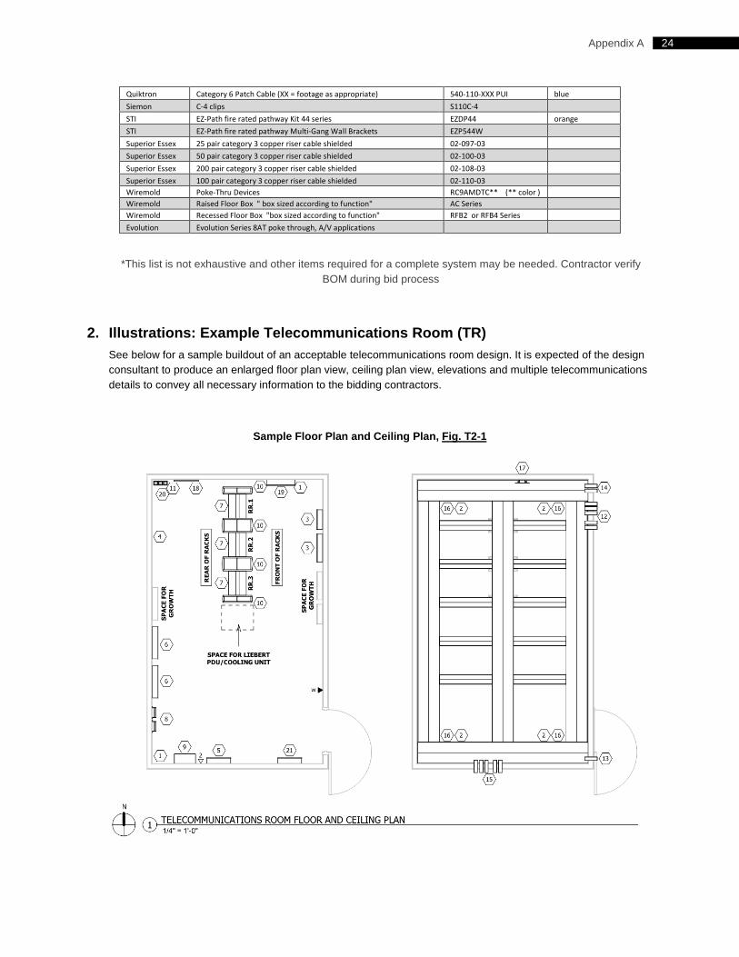
24 Appendix A
Quiktron Category 6 Patch Cable (XX = footage as appropriate) 540-110-XXX PUI blue Siemon C-4 clips S110C-4 STI EZ-Path fire rated pathway Kit 44 series EZDP44 orange STI EZ-Path fire rated pathway Multi-Gang Wall Brackets EZP544W Superior Essex 25 pair category 3 copper riser cable shielded 02-097-03 Superior Essex 50 pair category 3 copper riser cable shielded 02-100-03 Superior Essex 200 pair category 3 copper riser cable shielded 02-108-03 Superior Essex 100 pair category 3 copper riser cable shielded 02-110-03 Wiremold Poke-Thru Devices RC9AMDTC** (** color ) Wiremold Raised Floor Box " box sized according to function" AC Series Wiremold Recessed Floor Box "box sized according to function" RFB2 or RFB4 Series Evolution Evolution Series 8AT poke through, A/V applications
*This list is not exhaustive and other items required for a complete system may be needed. Contractor verify BOM during bid process
2. Illustrations: Example Telecommunications Room (TR) See below for a sample buildout of an acceptable telecommunications room design. It is expected of the design consultant to produce an enlarged floor plan view, ceiling plan view, elevations and multiple telecommunications details to convey all necessary information to the bidding contractors.
Sample Floor Plan and Ceiling Plan, Fig. T2-1
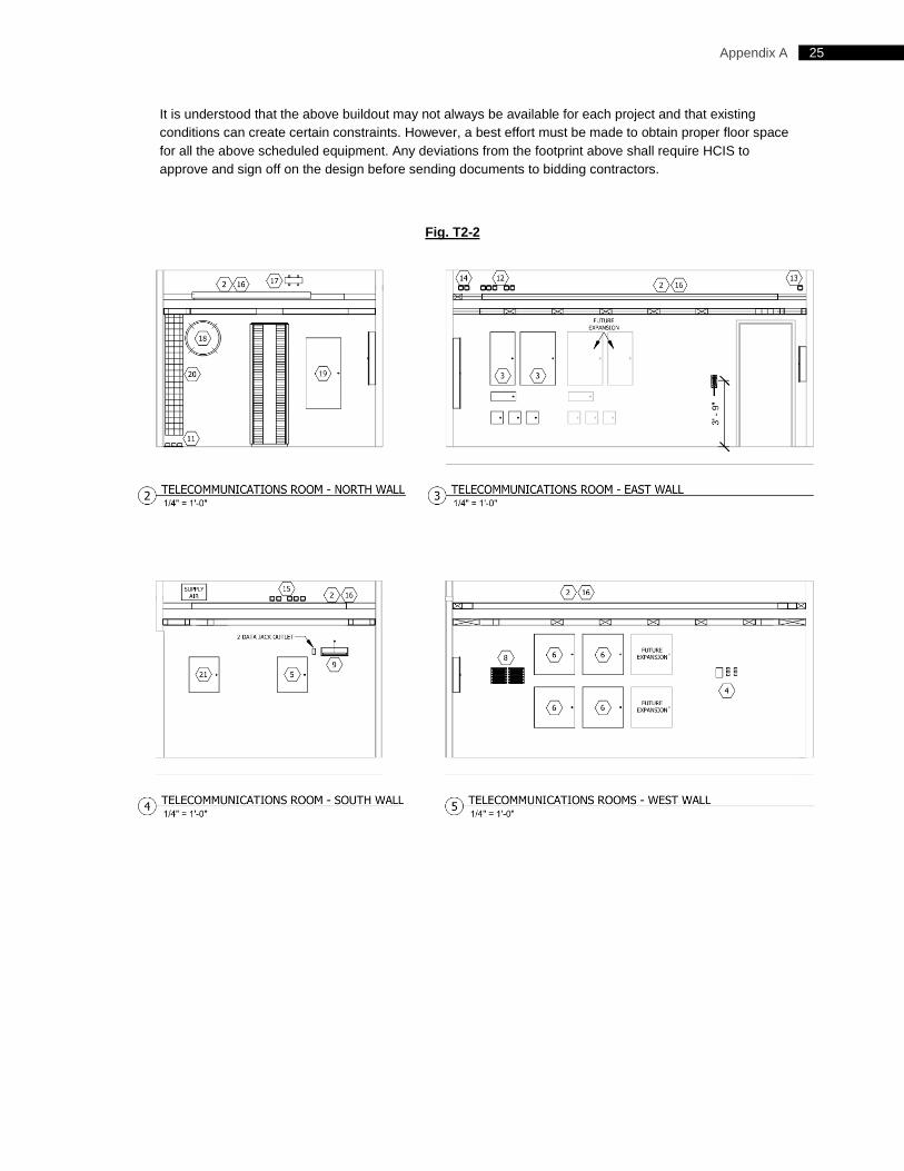
25 Appendix A
It is understood that the above buildout may not always be available for each project and that existing conditions can create certain constraints. However, a best effort must be made to obtain proper floor space for all the above scheduled equipment. Any deviations from the footprint above shall require HCIS to approve and sign off on the design before sending documents to bidding contractors.
Fig. T2-2
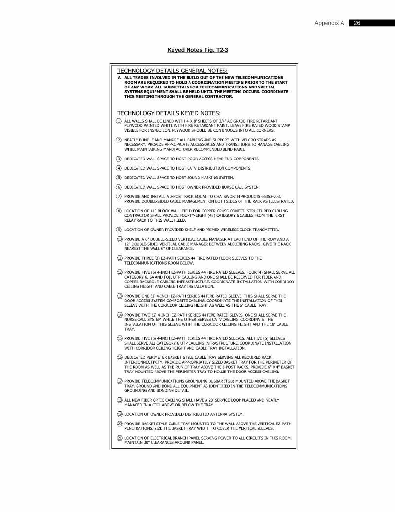
26 Appendix A
Keyed Notes Fig. T2-3
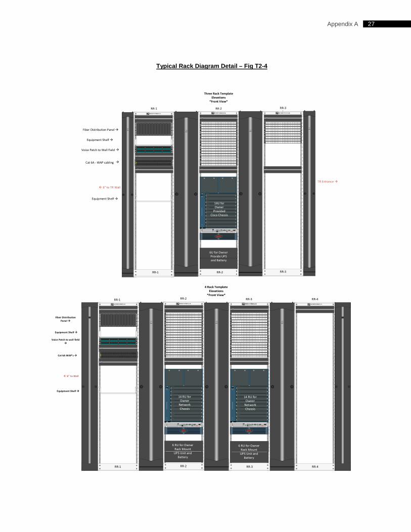
27 Appendix A
Typical Rack Diagram Detail – Fig T2-4
45
44
43
42
41
40
39
38
37
36
35
34
33
32
31
30
29
28
27
26
25
24
23
22
21
20
19
18
17
16
15
14
13
12
11
10
9
8
7
6
5
4
3
2
1
45
44
43
42
41
40
39
38
37
36
35
34
33
32
31
30
29
28
27
26
25
24
23
22
21
20
19
18
17
16
15
14
13
12
11
10
9
8
7
6
5
4
3
2
1
45
44
43
42
41
40
39
38
37
36
35
34
33
32
31
30
29
28
27
26
25
24
23
22
21
20
19
18
17
16
15
14
13
12
11
10
9
8
7
6
5
4
3
2
1
1
2
3
4
Catalyst4510R
5
6
7
FANSTATUS
8
9
10FLEX-SLOT
Three Rack Template9levations
*Cront View*
RR-2RR-1 RR-3
TR Entrance
6" to TR Wall
Cat 6A - WAP cabling
14U for Owner
Provided Cisco Chassis
6U for Owner Provide UPS and Battery
RR-3RR-1 RR-2
Voice Patch to Wall Field
RTN
IN
+24
EPOEmergencyPower Off
FunctionSource A SensitivitySource B SensitivitySource PreferenceSource A Xfer VoltageSource B Xfer Voltage
Status Select
Normal
Source ANarrow
Normal
Narrow
BrightReduc ed
Source BMedium
Reduc ed
Medium
DimLow
NoneWide
Low
Wide
Off
LevelSelectStatus To UPS B To UPS A To ServerAC Source
AB
Bright Source Seleceted
Dim Source OK, but not selected
Off Source not OK Redundant Switchwww.apcc.com
www.apcc.com
Fiber Distribution Panel
24
72
48
1
49
25
®
24
72
48
1
49
25
®
24
72
48
1
49
25
®
24
72
48
1
49
25
®
24
72
48
1
49
25
®
24
72
48
1
49
25
®
1
®
2 3 4 5 6 7 8 9 10 11 12 13 14 15 16 17 18 19 20 21 22 23 24
25 26 27 28 29 30 31 32 33 34 35 36 37 38 39 40 41 42 43 44 45 46 47 48
24
72
48
1
49
25
®
24
72
48
1
49
25
®
24
72
48
1
49
25
®Equipment Shelf
Equipment Shelf
®
1 2 3 4 5 6 7 8 9 10 11 12 13 14 15 16 17 18 19 20 21 22 23 24
25 26 27 28 29 30 31 32 33 34 35 36 37 38 39 40 41 42 43 44 45 46 47 48
45
44
43
42
41
40
39
38
37
36
35
34
33
32
31
30
29
28
27
26
25
24
23
22
21
20
19
18
17
16
15
14
13
12
11
10
9
8
7
6
5
4
3
2
1
45
44
43
42
41
40
39
38
37
36
35
34
33
32
31
30
29
28
27
26
25
24
23
22
21
20
19
18
17
16
15
14
13
12
11
10
9
8
7
6
5
4
3
2
1
45
44
43
42
41
40
39
38
37
36
35
34
33
32
31
30
29
28
27
26
25
24
23
22
21
20
19
18
17
16
15
14
13
12
11
10
9
8
7
6
5
4
3
2
1
45
44
43
42
41
40
39
38
37
36
35
34
33
32
31
30
29
28
27
26
25
24
23
22
21
20
19
18
17
16
15
14
13
12
11
10
9
8
7
6
5
4
3
2
1
1
2
3
4
Catalyst4510R
5
6
7
FANSTATUS
8
9
10FLEX-SLOT
4 Rack Template9levations
*Cront View*
RR-1 RR-2 RR-3 RR-4
Voice tatch to wall field
6" to Wall
Cat 6A WAt’s
6 RU for Owner Rack Mount UPS Unit and
Battery
6 RU for Owner Rack Mount UPS Unit and
Battery
14 RU for Owner
Network Chassis 14 RU for
Owner Network Chassis
1
2
3
4
Catalyst4510R
5
6
7
FANSTATUS
8
9
10FLEX-SLOT
14 RU for Owner
Network Chassis
Ciber 5istribution tanel
RR-1 RR-2 RR-3 RR-4
www.apcc.com www.apcc.com
RTN
IN
+24
EPOEmergencyPower Off
FunctionSource A SensitivitySource B SensitivitySource PreferenceSource A Xfer VoltageSource B Xfer Voltage
Status Select
Normal
Source ANarrow
Normal
Narrow
BrightReduc ed
Source BMedium
Reduc ed
Medium
DimLow
NoneWide
Low
Wide
Off
LevelSelectStatus To UPS B To UPS A To ServerAC Source
AB
Bright Source Seleceted
Dim Source OK, but not selected
Off Source not OK Redundant Switchwww.apcc.com
24
72
48
1
49
25
®
24
72
48
1
49
25
®
24
72
48
1
49
25
®
24
72
48
1
49
25
®
24
72
48
1
49
25
®
24
72
48
1
49
25
®
1
®
2 3 4 5 6 7 8 9 10 11 12 13 14 15 16 17 18 19 20 21 22 23 24
25 26 27 28 29 30 31 32 33 34 35 36 37 38 39 40 41 42 43 44 45 46 47 48
9quipment Shelf
9quipment Shelf
24
72
48
1
49
25
®
24
72
48
1
49
25
®
24
72
48
1
49
25
®
24
72
48
1
49
25
®
24
72
48
1
49
25
®
24
72
48
1
49
25
®
®
1 2 3 4 5 6 7 8 9 10 11 12 13 14 15 16 17 18 19 20 21 22 23 24
25 26 27 28 29 30 31 32 33 34 35 36 37 38 39 40 41 42 43 44 45 46 47 48
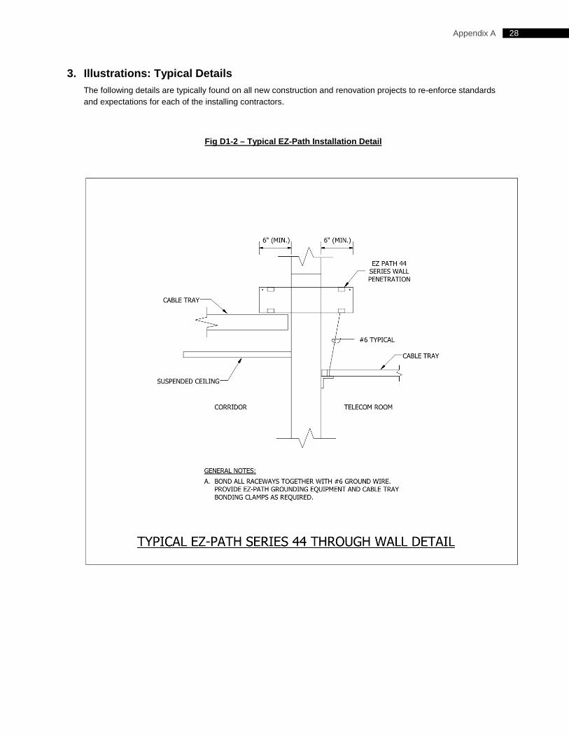
28 Appendix A
3. Illustrations: Typical Details The following details are typically found on all new construction and renovation projects to re-enforce standards and expectations for each of the installing contractors.
Fig D1-2 – Typical EZ-Path Installation Detail
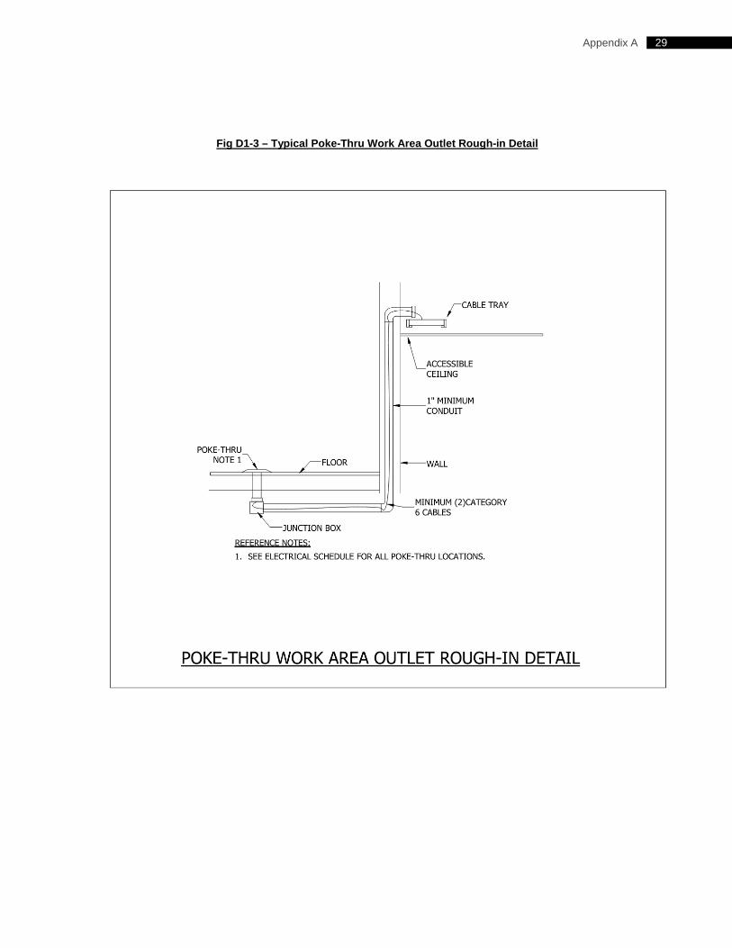
29 Appendix A
Fig D1-3 – Typical Poke-Thru Work Area Outlet Rough-in Detail
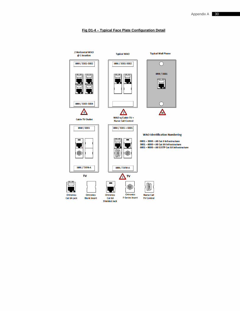
30 Appendix A
Fig D1-4 – Typical Face Plate Configuration Detail
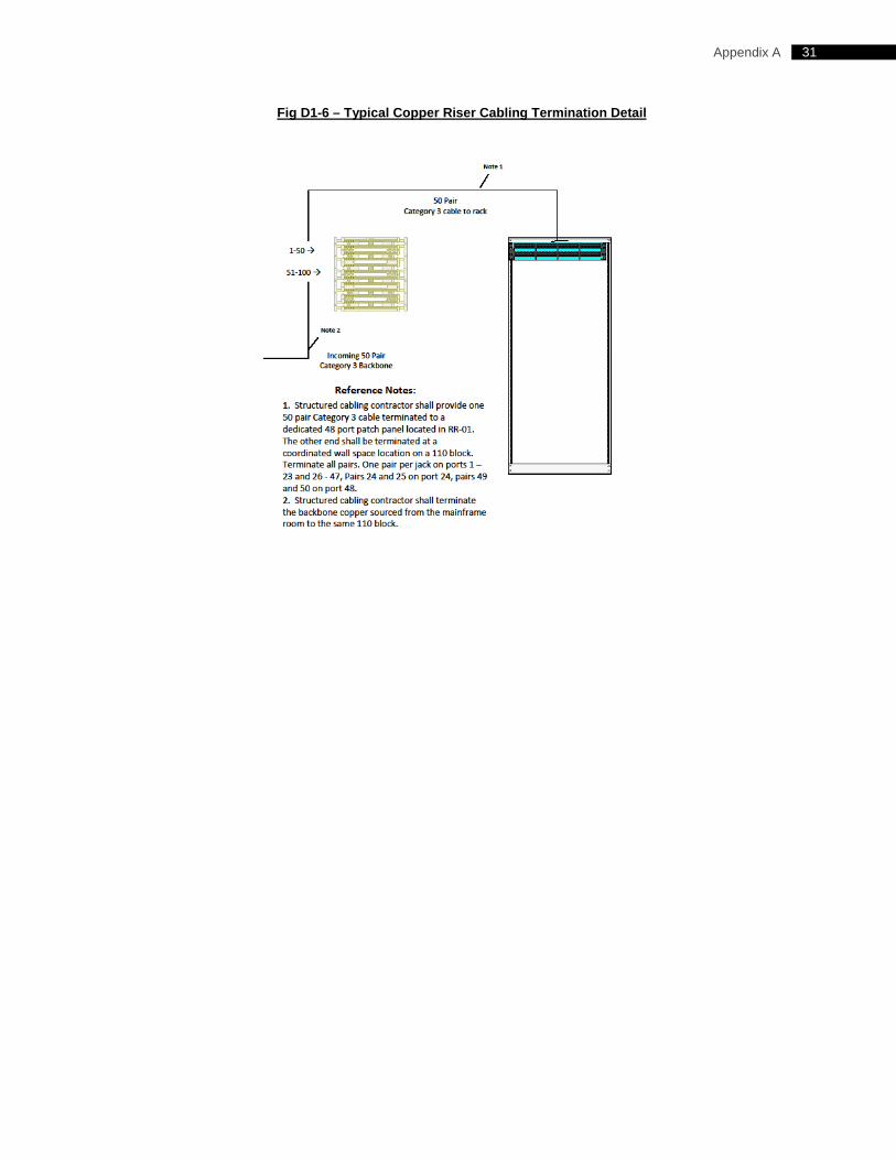
31 Appendix A
Fig D1-6 – Typical Copper Riser Cabling Termination Detail
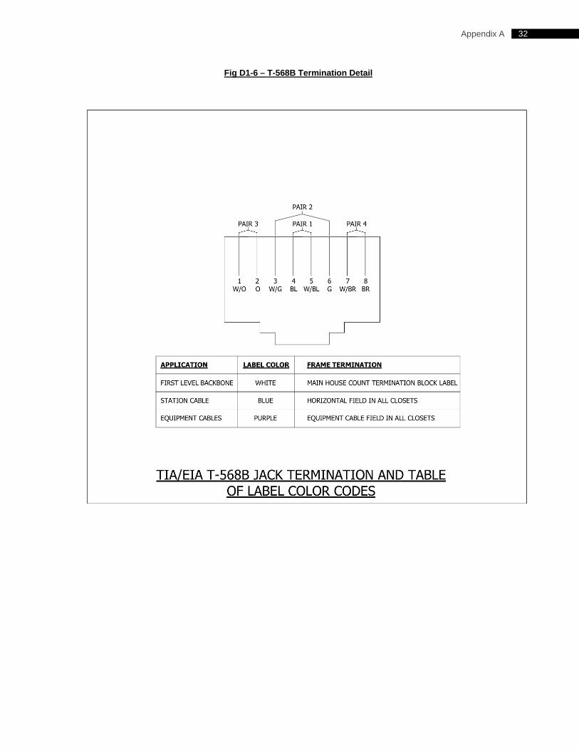
32 Appendix A
Fig D1-6 – T-568B Termination Detail
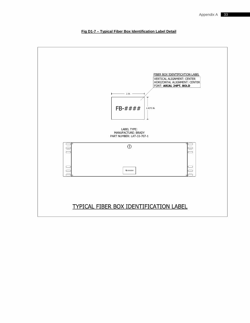
33 Appendix A
Fig D1-7 – Typical Fiber Box Identification Label Detail
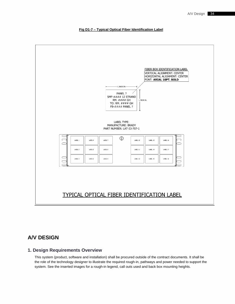
34 A/V Design
Fig D1-7 – Typical Optical Fiber Identification Label
A/V DESIGN
1. Design Requirements Overview This system (product, software and installation) shall be procured outside of the contract documents. It shall be the role of the technology designer to illustrate the required rough-in, pathways and power needed to support the system. See the inserted images for a rough-in legend, call outs used and back box mounting heights.
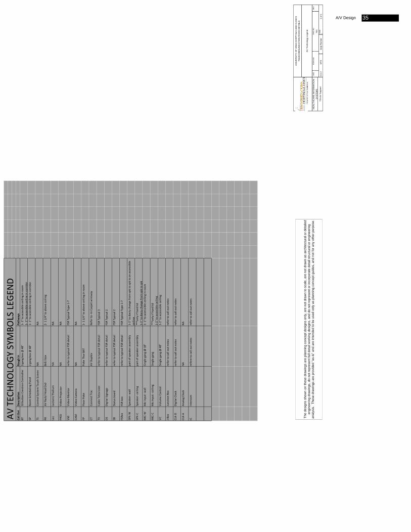
The
desi
gns
show
n on
thes
e dr
awin
gs a
re p
lann
ing
conc
ept d
esig
ns o
nly,
are
not
dra
wn
to s
cale
, are
not
dra
wn
as a
rchi
tect
ural
or d
etai
led
engi
neer
ing
draw
ings
, do
not r
epre
sent
full
deta
il w
orki
ng d
esig
ns, a
nd d
o no
t rep
rese
nt o
r inc
orpo
rate
det
ail s
truct
ural
or e
ngin
eerin
g an
alys
is.
Thes
e dr
awin
gs a
re p
rovi
ded
“as-
is” a
nd a
re in
tend
ed to
be
used
onl
y as
pla
nnin
g co
ncep
t gui
des,
and
not
for a
ny o
ther
pur
pose
.H
EA
LTH
CA
RE
INFO
RM
ATI
ON
S
YS
TEM
S
TSI A
V S
uppo
rt
UN
IVER
SIT
Y O
F IO
WA
HO
SP
ITA
LS A
ND
CLI
NIC
STE
LEC
OM
MU
NIC
ATIO
N R
OO
M D
ETA
ILS
AV
Tec
hnol
ogy
Lege
nd
SIZ
EFS
CM
NO
DW
G N
OR
EV
T01
SC
ALE
NTS
Jody
Rei
nier
SH
EE
T1
of 1
Call Out
Descrip
tion
Rough in
Pathways
BT10 button Crestron
Con
troller
3 gang
box
@ 48"
1‐ 1" to accesible ceiling
in ro
om
1‐ 1" to accesible ceiling
in co
rridor
SPRo
om Sched
uling Pane
l2 gang
box
@ 48"
1‐ 1" to accesible ceiling
in co
rridor
TSCo
ntrol System Tou
ch Scree
nNA
NA
RKAV
Rack/ Head End
8x8 J b
ox2‐ 1 1/4" to above ceiling
Lec
Lectern/ Pod
ium
NA
NA
PROJ
Vide
o Projector
NA
NA
VMVide
o Mon
itor
refer to typical FSR
detail
FSR Typical Type 1‐7
CAM
Vide
o Camera
NA
NA
FPFloo
r Poke
Poke
Thu
r 8AT
1‐ 1 1/4" to above ceiling
in ro
om
CTCo
nnect Trac
AV Dup
lex
Refer to ‐In
Carpe
t wire
way
TVCable Television
refer to typical FSR
detail
FSR Typical 3
DSDigital Signage
refer to typical FSR
detail
FSR Typical 2
SBStatus board
refer to typical FSR
detail
FSR Typical 2
FSRxx
FSR bo
xrefer to typical FSR
detail
FSR Typical Type 1‐7
SPK‐W
Speaker‐ wall
part of spe
aker assem
bly
1‐1" to
dasiy ch
ange
from
spk to sp
k to an accessible
ceiling
SPK‐C
Speaker‐ ce
iling
part of spe
aker assem
bly
***only if hard lid
1‐1" to
dasiy ch
ange
from
spk to sp
kMIC‐W
Mic inpu
t‐ wall
Single gang @ 18"
1‐ 1" to accessible ce
iling
in ro
om
MIC‐C
Mic Inpu
t‐ ce
iling
Single gang
***only if hard lid
1‐1" to
accesible ce
iling
VCVo
lume Co
ntrol
Single gang @ 48"
1‐1" to
accessible ceiling
J Box
Junctio
n Bo
xrefer to call ou
t notes
refer to call ou
t notes
CLK‐D
Digital Clock
refer to call ou
t notes
refer to call ou
t notes
CLK‐A
Analog
Clock
NA
NA
ICIntercom
refere to
call ou
t notes
refer to call ou
t notes
AV TEC
HNOLO
GY SYM
BOLS LEG
END
A/V Design 35
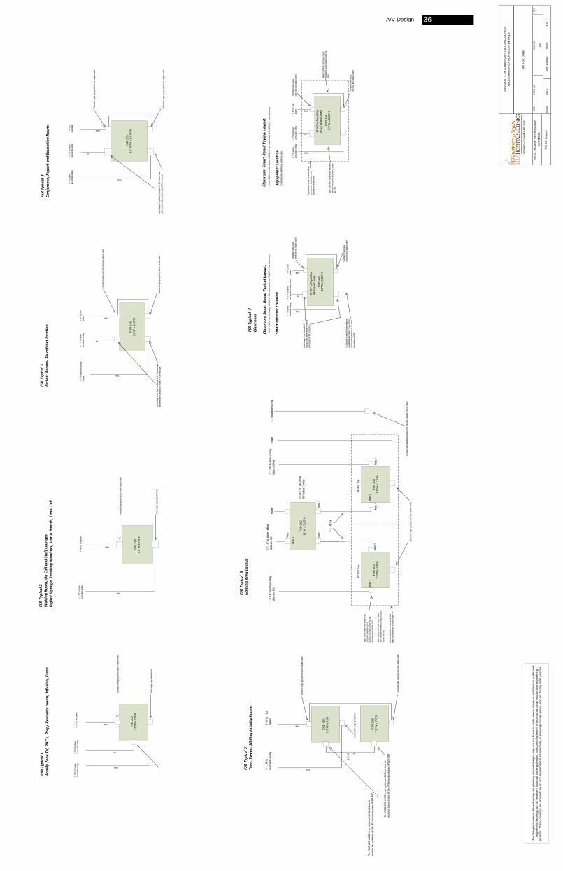
FSR
100
11"W
x 5
.25"
HFS
R 2
007.
5"W
x 7
.5"H
The PW
B‐2X
0‐AV
BB is an op
tiona
l AV ba
ck box to
enclose the exterio
r of the
IPS knockout area (PWB‐20
0
FSR Typical 1
Family Zon
e TV
, PAC
U, Prep/ Recovery room
s, In
fusion
, Exam
1- 1
¼” to
abov
e ac
cess
ible c
eiling
1- ¾
” to J
box p
ower
1- 1
1/4” t
o abo
ve
acce
ssibl
e ceil
ing Data
AV
PWR
FSR Typical 2
Waitin
g Ro
om, O
n Ca
ll an
d Staff Lou
nges
Digita
l Signa
ge, Tracking Mon
itors, Status B
oards, Omni Cell
FSR
200
7.5"
W x
7.5
"H
Stan
dard
sing
le ga
ng el
ectric
al bo
x- du
plex o
utlet
Data
PWR
FSR Typical 3
Patie
nt Roo
ms‐ AV cabine
t location
1- ¾
” to J
box
powe
r PWR
Stan
dard
sing
le ga
ng el
ectric
al bo
x- du
plex o
utlet
Deep
sing
le ga
ng el
ectric
al bo
xSt
anda
rd si
ngle
gang
elec
trical
box-
duple
x outl
et
FSR
270
14.7
5"W
x 1
0.50
"H
Low
Volta
ge E
ntry B
ox(1
inclu
ded)
for I
PS In
serts
- data
wi
ll ter
mina
te in
biscu
it jac
k ins
ide of
FSR
enclo
sure
Data
1- 1
¼” to
abov
e ac
cess
ible c
eiling
AV
Stan
dard
sing
le ga
ng el
ectric
al bo
x- du
plex o
utlet
Deep
sing
le ga
ng el
ectric
al bo
x
FSR Typical 4
Conferen
ce, R
eport a
nd Edu
catio
n Ro
oms
1- ¾
” to J
bo
x pow
er
PWR
Stan
dard
sing
le ga
ng el
ectric
al bo
x- du
plex o
utlet
Stan
dard
sing
le ga
ng el
ectric
al bo
x- du
plex o
utlet
Data
1- 1”
to ab
ove
acce
ssibl
e ceil
ing1-
1 ¼”
to ab
ove
acce
ssibl
e ceil
ing
AV
FSR
200
7.5"
W x
7.5
"H
Data
AV
PWR
Stan
dard
sing
le ga
ng el
ectric
al bo
x- du
plex o
utlet
Deep
sing
le ga
ng el
ectric
al bo
x
FSR
200
7.5"
W x
7.5
"H
1- 1
¼”
1- ¾
” to J
box
powe
r1-
1 1/4
” to
acce
ssibl
e ceil
ing
FSR Typical 5
Teen
, Tween, Sibiling
Activity
Roo
ms
The
desi
gns
show
n on
thes
e dr
awin
gs a
re p
lann
ing
conc
ept d
esig
ns o
nly,
are
not
dra
wn
to s
cale
, are
not
dra
wn
as a
rchi
tect
ural
or d
etai
led
engi
neer
ing
draw
ings
, do
not r
epre
sent
full
deta
il w
orki
ng d
esig
ns, a
nd d
o no
t rep
rese
nt o
r inc
orpo
rate
det
ail s
truct
ural
or e
ngin
eerin
g an
alys
is.
Thes
e dr
awin
gs a
re p
rovi
ded
“as-
is” a
nd a
re in
tend
ed to
be
used
onl
y as
pla
nnin
g co
ncep
t gui
des,
and
not
for a
ny o
ther
pur
pose
.
Low
Volta
ge E
ntry B
ox(1
inclu
ded)
for I
PS In
serts
- data
wi
ll ter
mina
te in
biscu
it jac
k ins
ide of
FSR
enclo
sure
The PW
B‐2X
0‐AV
BB is an op
tiona
l AV ba
ck box to
enclose the exterio
r of the
IPS knockout area (PWB‐20
0
1- 1
1/4” t
o abo
ve
acce
ssibl
e ceil
ing1-
¾” t
o J bo
x pow
er1-
1" to
abov
e acc
essib
le ce
iling
Stan
dard
sing
le ga
ng el
ectric
al bo
x- du
plex o
utlet
FSR
200
7.5"
W x
7.5
"HFS
R 2
007.
5"W
x 7
.5"H
FSR
100
11"W
x 5
.25"
H
1- 1
1/4” t
o abo
ve ce
iling
(data
and A
V)
Stan
dard
sing
le ga
ng el
ectric
al bo
x- du
plex o
utlet
Powe
rPo
wer
1- 1
1/4” t
o abo
ve ce
iling
(data
and A
V)
1- 1
1/4” t
o abo
ve ce
iling
(data
and A
V)
Note 1:The PW
B‐2X
0‐AV
BB is an
optio
nal A
V ba
ck box to
enclose the exterio
r of the
IPS
knockout area (PWB‐200
1- 1
1/4” A
V
Note
1
Note
1
Note
1
Note
1No
te 1
FSR Typical 6
Gam
ing Area
Layou
t
Note
1
Repr
esen
ts ca
binet
or ca
sewo
rk- fin
al de
tails
to be
prov
ided b
y Ann
e Bau
er
72" A
FF to
Top
of B
ox
(69"
to bo
x Cen
ter)
18" A
FF T
op18
" AFF
Top
4 squ
are w
ith si
ngle
gang
redu
cer f
or m
ic jac
k- loc
ation
TBD
by H
eery
1- 1"
to ab
ove c
eiling
Note 2:Each FSR
shall have 2 da
ta
wire
runs te
rminated
in a bisc
uit jack
insid
e the FSR
Note
2
Note
2No
te 2
Classroo
m Smart B
oard Typical Layou
t:
FSR
100
11"W
x 5
.25"
H1- ¾
” to J
box
powe
r PWR
Stan
dard
sing
le ga
ng
electr
ical b
ox- d
uplex
outle
t
Stan
dard
sing
le ga
ng
electr
ical b
ox- d
uplex
outle
t
Low
Volta
ge E
ntry B
oxes
for I
PS
Inser
ts. D
ata w
ill ter
mina
te in
biscu
it jac
k ins
ide of
FSR
enclo
sure
.
Data
AV 72" A
FF to
Top
of B
ox
(69"
to bo
x Cen
ter)
Repr
esen
ts cu
t-out
in re
ar of
cabin
et or
case
work-
final
detai
ls to
be
prov
ided b
y Ann
e Bau
er
Note:
Eac
h FSR
shall
have
4 da
ta wi
re
runs
term
inated
in a
biscu
it jac
k ins
ide
the F
SR
Smart M
onito
r Location
Equipm
ent Location
Confi
rm lo
catio
n with
Hee
ry an
d Ann
e Bau
er
FSR
100
11"W
x 5
.25"
H1- ¾
” to J
box
powe
r PWR
Stan
dard
sing
le ga
ng
electr
ical b
ox- d
uplex
outle
t
Stan
dard
sing
le ga
ng
electr
ical b
ox- d
uplex
outle
t
Data
AV 18" A
FF to
Top
of B
ox
(14.2
5" to
box C
enter
)No
te: E
ach F
SR sh
all ha
ve 2
dual
rece
ptacle
powe
r outl
ets in
side t
he
FSR
room
s 122
20-B
(1sr
floor
libra
ry), 1
0222
2 (10
th floo
r reh
ab ro
om),
and 1
1222
2 (11
th floo
r reh
ab ro
om)
Classroo
m Smart B
oard Typical Layou
t:
1- 1”
to ab
ove
acce
ssibl
e ceil
ing1-
1 ¼”
to ab
ove
acce
ssibl
e ceil
ing
1- 1”
to ab
ove
acce
ssibl
e ceil
ing1-
1 ¼”
to ab
ove
acce
ssibl
e ceil
ing in
room
room
s 122
20-B
(1sr
floor
libra
ry), 1
0222
2 (10
th floo
r reh
ab ro
om),
and 1
1222
2 (11
th floo
r reh
ab ro
om)
¾” pl
ywoo
d or m
etal b
ackin
g req
uired
dir
ectly
below
FSR
box.
Span
3 stu
d ca
vities
wide
, mini
mum
of 16
" dow
n fro
m bo
ttom
of FS
R.
FSR Typical 7
Clasrroo
m
HE
ALT
HC
AR
E IN
FOR
MA
TIO
N
SY
STE
MS
TSI A
V S
uppo
rt
UN
IVER
SIT
Y O
F IO
WA
HO
SP
ITA
LS A
ND
CLI
NIC
STE
LEC
OM
MU
NIC
ATIO
N R
OO
M D
ETA
ILS
AV
FS
R D
etai
l
SIZ
EFS
CM
NO
DW
G N
OR
EV
T01
SC
ALE
NTS
Jody
Rei
nier
SH
EET
1 of
1A/V Design 36
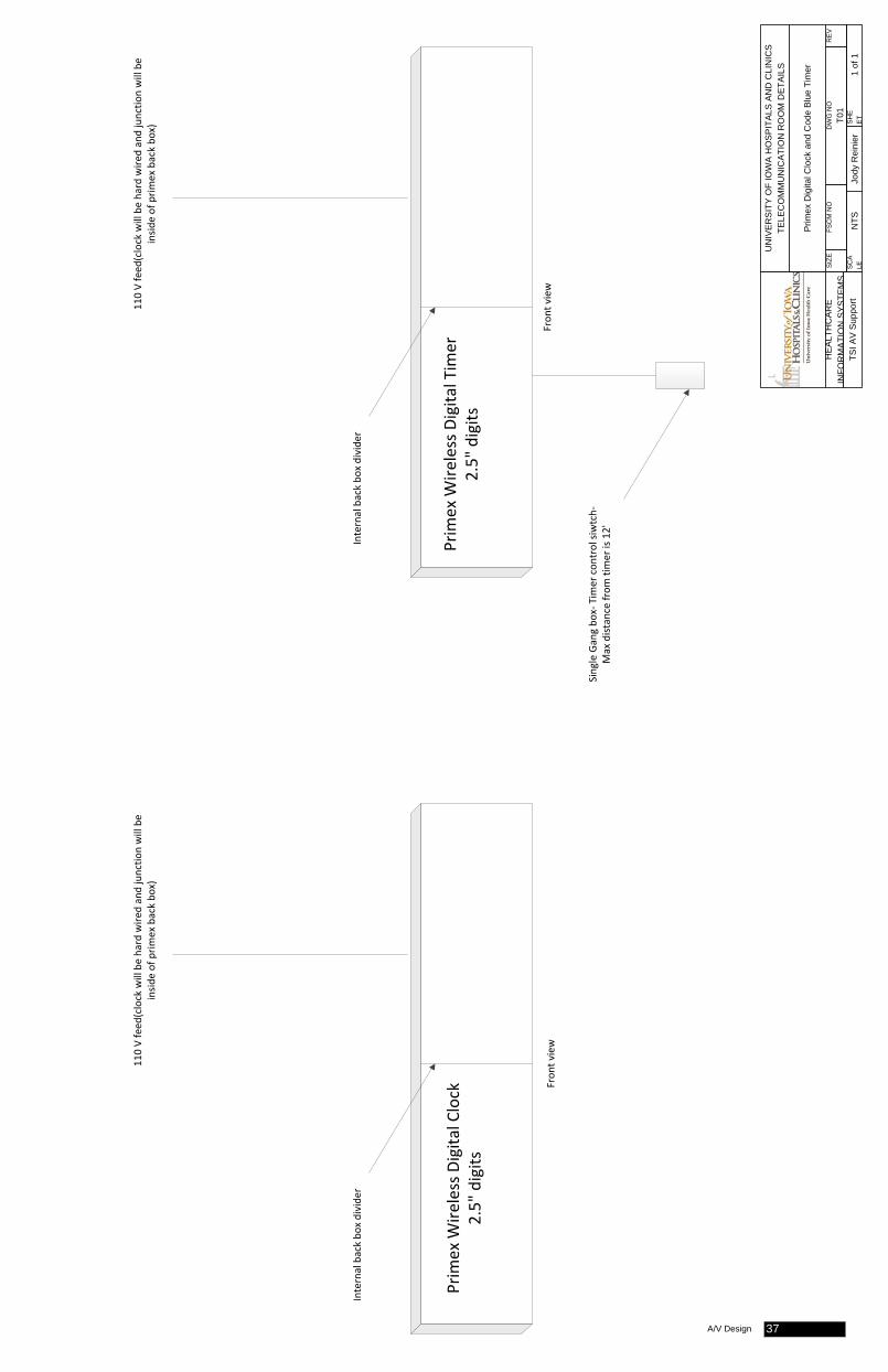
Prim
ex W
ireless Digita
l Tim
er
2.5" digits
Prim
ex W
ireless Digita
l Clock
2.5" digits
110 V feed
(clock will be hard wire
d and junctio
n will be
insid
e of prim
ex back bo
x)
Internal back bo
x divide
r
Fron
t view
Internal back bo
x divide
r
Single Gang bo
x‐ Tim
er con
trol siwtch‐
Max distance from
timer is 12'
110 V feed
(clock will be hard wire
d and junctio
n will be
insid
e of prim
ex back bo
x)
Fron
t view
HE
ALT
HC
AR
E IN
FOR
MA
TIO
N S
YS
TEM
STS
I AV
Sup
port
UN
IVER
SIT
Y O
F IO
WA
HO
SP
ITA
LS A
ND
CLI
NIC
STE
LEC
OM
MU
NIC
ATIO
N R
OO
M D
ETA
ILS
Prim
ex D
igita
l Clo
ck a
nd C
ode
Blu
e Ti
mer
SIZ
EFS
CM
NO
DW
G N
OR
EV
T01
SC
ALE
NTS
Jody
Rei
nier
SH
EE
T1
of 1
A/V Design 37
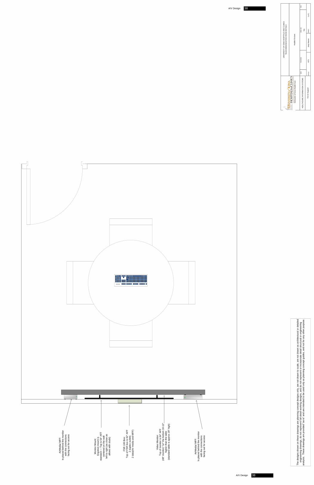
FSR
100
Box
:To
p of
FS
R b
ox is
62"
AFF
2 du
plex
out
lets
2 da
ta(A
ir m
edia
and
MFF
)
Mon
itor M
ount
:E
rgot
ron
mou
nt is
stan
dard
— T
op is
54”
AFF
cent
ered
on
the
wal
lle
ft to
righ
t (as
clo
se a
sal
low
s w
ith s
tuds
)
AirM
edia
/ MFF
:Is
pla
ced
behi
nd th
e m
onito
rw
ith th
e co
nnec
tions
faci
ng o
ut fo
r acc
ess
Vid
eo M
onito
r:To
p of
mon
itor i
s 64
" AFF
(48”
mon
itor)
*or*
the
botto
m 1
0-12
" h
ighe
r tha
n th
e ta
ble
(sta
ndar
d ta
ble
is a
ppro
x 29
” hig
h)
AirM
edia
/ MFF
:Is
pla
ced
behi
nd th
e m
onito
rw
ith th
e co
nnec
tions
faci
ng o
ut fo
r acc
ess
The
desi
gns
show
n on
thes
e dr
awin
gs a
re p
lann
ing
conc
ept d
esig
ns o
nly,
are
not
dra
wn
to s
cale
, are
not
dra
wn
as a
rchi
tect
ural
or d
etai
led
engi
neer
ing
draw
ings
, do
not r
epre
sent
full
deta
il w
orki
ng d
esig
ns, a
nd d
o no
t rep
rese
nt o
r inc
orpo
rate
det
ail s
truct
ural
or e
ngin
eerin
g an
alys
is.
Thes
e dr
awin
gs a
re p
rovi
ded
“as-
is” a
nd a
re in
tend
ed to
be
used
onl
y as
pla
nnin
g co
ncep
t gui
des,
and
not
for a
ny o
ther
pur
pose
.H
EA
LTH
CA
RE
INFO
RM
ATI
ON
SY
STE
MS
TSI A
V S
uppo
rt
UN
IVER
SIT
Y O
F IO
WA
HO
SP
ITA
LS A
ND
CLI
NIC
STE
LEC
OM
MU
NIC
ATIO
N R
OO
M D
ETA
ILS
Hud
dle/
Enc
lave
SIZ
EFS
CM
NO
DW
G N
OR
EV
T01
SC
ALE
NTS
Jody
Rei
nier
SH
EET
1 of
1
A/V Design 38
A/V Design 38
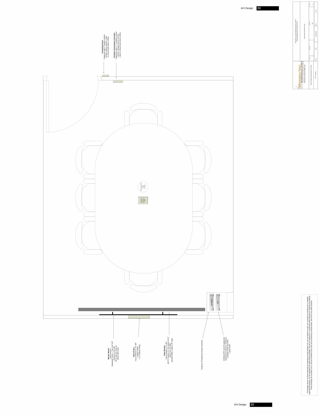
HE
ALT
HC
AR
E IN
FOR
MA
TIO
N S
YS
TEM
S
TSI A
V S
uppo
rt
UN
IVER
SIT
Y O
F IO
WA
HO
SP
ITA
LS A
ND
CLI
NIC
STE
LEC
OM
MU
NIC
ATIO
N R
OO
M D
ETA
ILS
Typi
cal S
mal
l Con
fere
nce
Roo
m
SIZ
EFS
CM
NO
DW
G N
OR
EV
T01
2
SC
ALE
NTS
Jody
Rei
nier
SH
EET
1 of
1
FSR
270
Box
:To
p of
FS
R b
ox is
72"
AFF
2 du
plex
out
lets
1 ¼
” to
abov
e ce
iling
Mon
itor M
ount
:C
hief
mou
nt is
Sta
ndar
d(LT
m1U
) — T
op is
64”
AFF
cent
ered
on
the
wal
lle
ft to
righ
t (as
clo
se a
sal
low
s w
ith s
tuds
)
Vide
o M
onito
r:To
p of
mon
itor i
s 74
" AFF
(60-
70" m
onito
r) *
or*
the
botto
m 1
0-12
" h
ighe
r tha
n th
e ta
ble
(sta
ndar
d ta
ble
is a
ppro
x 29
” hig
h)
8AT Evolution Po
ke1 ¼” AV
1" Data
¾” Po
wer
Altin
ex box
with
AV
conn
ectio
ns
in ta
ble
Air
Med
ia
SFF
Cre
denz
a- P
rovi
ded
by fu
rnitu
re c
ontra
ctor
Sche
dulin
g Pa
nel
2 ga
ng b
ox w
ith 1
" con
duit
to a
bove
co
rrid
or c
eilin
g, re
quire
s 1
data
in
a b
iscu
it ja
ck a
bove
cei
ling
10 B
utto
n Pr
esen
tatio
n C
ontr
olle
r3
gang
box
with
2- 1
" con
duits
to a
bove
co
rrid
or c
eilin
g(1)
and
in ro
om(1
), 1
dat
a in
a b
iscu
it ja
ck a
bove
cei
ling
AirM
edia
/ SFF
and
AV
equ
ipm
ent:
Equ
ipm
ent i
s pl
aced
in C
rede
nza
2 da
ta(A
ir m
edia
and
SFF
) 1
quad
out
let
The
desi
gns
show
n on
thes
e dr
awin
gs a
re p
lann
ing
conc
ept d
esig
ns o
nly,
are
not
dra
wn
to s
cale
, are
not
dra
wn
as a
rchi
tect
ural
or d
etai
led
engi
neer
ing
draw
ings
, do
not r
epre
sent
full
deta
il w
orki
ng d
esig
ns, a
nd d
o no
t rep
rese
nt o
r inc
orpo
rate
det
ail s
truct
ural
or e
ngin
eerin
g an
alys
is.
Thes
e dr
awin
gs a
re p
rovi
ded
“as-
is” a
nd a
re in
tend
ed to
be
used
onl
y as
pla
nnin
g co
ncep
t gui
des,
and
not
for a
ny o
ther
pur
pose
.
A/V Design 39
A/V Design 39
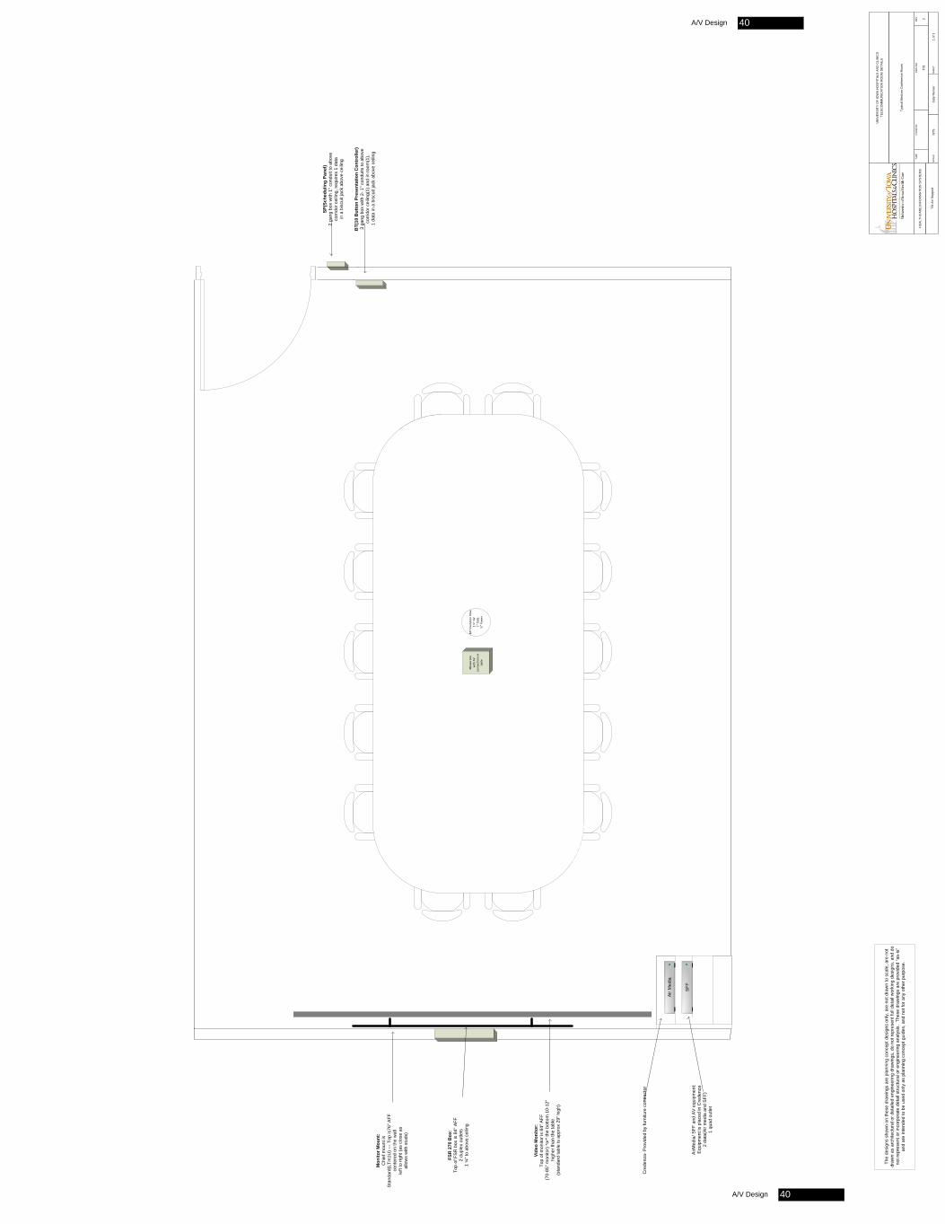
HE
ALT
HC
AR
E IN
FOR
MA
TIO
N S
YS
TEM
S
TSI A
V S
uppo
rt
UN
IVER
SIT
Y O
F IO
WA
HO
SP
ITA
LS A
ND
CLI
NIC
STE
LEC
OM
MU
NIC
ATIO
N R
OO
M D
ETA
ILS
Typi
cal M
ediu
m C
onfe
renc
e R
oom
SIZ
EFS
CM
NO
DW
G N
OR
EV
T01
2
SC
ALE
NTS
Jody
Rei
nier
SH
EET
1 of
1
FSR
270
Box
:To
p of
FS
R b
ox is
84"
AFF
2 du
plex
out
lets
1 ¼
” to
abov
e ce
iling
Mon
itor M
ount
:C
hief
mou
nt is
Sta
ndar
d(LT
m1U
) — T
op is
76” A
FFce
nter
ed o
n th
e w
all
left
to ri
ght (
as c
lose
as
allo
ws
with
stu
ds)
Vide
o M
onito
r:To
p of
mon
itor i
s 84
" AFF
(70-
85" m
onito
r) *
or*
the
botto
m 1
0-12
" h
ighe
r tha
n th
e ta
ble
(sta
ndar
d ta
ble
is a
ppro
x 29
” hig
h)
AirM
edia
/ SFF
and
AV
equ
ipm
ent:
Equ
ipm
ent i
s pl
aced
in C
rede
nza
2 da
ta(A
ir m
edia
and
SFF
) 1
quad
out
let
8AT Evolution Po
ke1 ¼” AV
1" Data
¾” Po
wer
Altin
ex box
with
AV
conn
ectio
ns in
table
Air
Med
ia
SFF
Cre
denz
a- P
rovi
ded
by fu
rnitu
re c
ontra
ctor
SP(S
ched
ulin
g Pa
nel)
2 ga
ng b
ox w
ith 1
" con
duit
to a
bove
co
rrid
or c
eilin
g, re
quire
s 1
data
in
a b
iscu
it ja
ck a
bove
cei
ling
BT(
10 B
utto
n Pr
esen
tatio
n C
ontr
olle
r)3
gang
box
with
2- 1
" con
duits
to a
bove
co
rrid
or c
eilin
g(1)
and
in ro
om(1
), 1
dat
a in
a b
iscu
it ja
ck a
bove
cei
ling
The
desi
gns
show
n on
thes
e dr
awin
gs a
re p
lann
ing
conc
ept d
esig
ns o
nly,
are
not
dra
wn
to s
cale
, are
not
dr
awn
as a
rchi
tect
ural
or d
etai
led
engi
neer
ing
draw
ings
, do
not r
epre
sent
full
deta
il w
orki
ng d
esig
ns, a
nd d
o no
t rep
rese
nt o
r inc
orpo
rate
det
ail s
truct
ural
or e
ngin
eerin
g an
alys
is.
Thes
e dr
awin
gs a
re p
rovi
ded
“as-
is”
and
are
inte
nded
to b
e us
ed o
nly
as p
lann
ing
conc
ept g
uide
s, a
nd n
ot fo
r any
oth
er p
urpo
se.
A/V Design 40
A/V Design 40
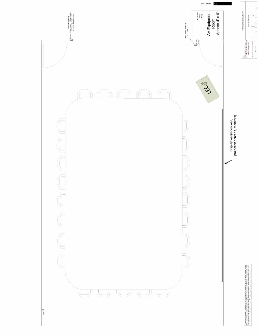
HE
ALT
HC
AR
E IN
FOR
MA
TIO
N S
YS
TEM
S
TSI A
V S
uppo
rt
UN
IVE
RS
ITY
OF
IOW
A H
OS
PIT
ALS
AN
D C
LIN
ICS
TELE
CO
MM
UN
ICA
TIO
N R
OO
M D
ETA
ILS
Typi
cal L
arge
Con
fern
ce R
oom
SIZ
EFS
CM
NO
DW
G N
OR
EV
T01
2
SC
ALE
NTS
Jody
Rei
nier
SH
EET
1 of
1
RK
(Rac
k /
Hea
d E
nd)
SP(S
ched
ulin
g Pa
nel)
2 ga
ng b
ox w
ith 1
" con
duit
to a
bove
co
rrid
or c
eilin
g, re
quire
s 1
data
in
a b
iscu
it ja
ck a
bove
cei
ling
4" E
Z pa
th
AV
Equ
ipm
ent
Roo
mA
ppro
x 4'
x 6
'
Dis
play
wal
l(vid
eo w
all,
proj
ectio
n sc
reen
s, m
onito
rs)
Car
d R
eade
r- p
rovi
de b
y S&
S
CA
M
8AT
Evolution
Poke
1 ¼” AV
1" Data
¾” Po
wer
The
desi
gns
show
n on
thes
e dr
awin
gs a
re p
lann
ing
conc
ept d
esig
ns o
nly,
are
not
dra
wn
to s
cale
, are
not
dr
awn
as a
rchi
tect
ural
or d
etai
led
engi
neer
ing
draw
ings
, do
not r
epre
sent
full
deta
il w
orki
ng d
esig
ns, a
nd d
o no
t rep
rese
nt o
r inc
orpo
rate
det
ail s
truct
ural
or e
ngin
eerin
g an
alys
is.
Thes
e dr
awin
gs a
re p
rovi
ded
“as-
is”
and
are
inte
nded
to b
e us
ed o
nly
as p
lann
ing
conc
ept g
uide
s, a
nd n
ot fo
r any
oth
er p
urpo
se.
A/V Design 41
Appendix F
Modified Bitumen Membrane Roofing (SBS) Specification (Section 07550)
November 1, 2016
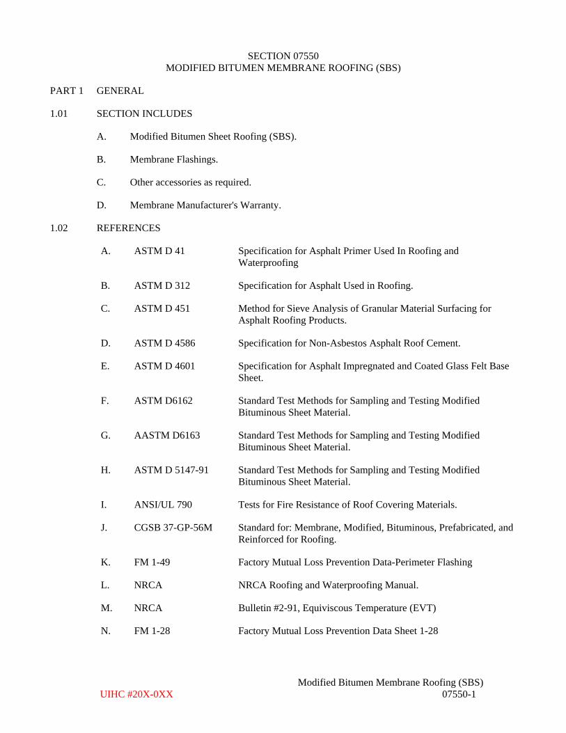
SECTION 07550 MODIFIED BITUMEN MEMBRANE ROOFING (SBS)
Modified Bitumen Membrane Roofing (SBS) UIHC #20X-0XX 07550-1
PART 1 GENERAL
1.01 SECTION INCLUDES
A. Modified Bitumen Sheet Roofing (SBS).
B. Membrane Flashings.
C. Other accessories as required.
D. Membrane Manufacturer's Warranty.
1.02 REFERENCES
A. ASTM D 41 Specification for Asphalt Primer Used In Roofing and Waterproofing
B. ASTM D 312 Specification for Asphalt Used in Roofing.
C. ASTM D 451 Method for Sieve Analysis of Granular Material Surfacing for Asphalt Roofing Products.
D. ASTM D 4586 Specification for Non-Asbestos Asphalt Roof Cement.
E. ASTM D 4601 Specification for Asphalt Impregnated and Coated Glass Felt Base Sheet.
F. ASTM D6162 Standard Test Methods for Sampling and Testing Modified Bituminous Sheet Material.
G. AASTM D6163 Standard Test Methods for Sampling and Testing Modified Bituminous Sheet Material.
H. ASTM D 5147-91 Standard Test Methods for Sampling and Testing Modified Bituminous Sheet Material.
I. ANSI/UL 790 Tests for Fire Resistance of Roof Covering Materials.
J. CGSB 37-GP-56M Standard for: Membrane, Modified, Bituminous, Prefabricated, and Reinforced for Roofing.
K. FM 1-49 Factory Mutual Loss Prevention Data-Perimeter Flashing
L. NRCA NRCA Roofing and Waterproofing Manual.
M. NRCA Bulletin #2-91, Equiviscous Temperature (EVT)
N. FM 1-28 Factory Mutual Loss Prevention Data Sheet 1-28
November 1, 2016
SECTION 07550 MODIFIED BITUMEN MEMBRANE ROOFING (SBS)
Modified Bitumen Membrane Roofing (SBS) UIHC #20X-0XX 07550-2
O. FM 1-29 Factory Mutual Loss Prevention Data Sheet 1-29
1.03 SYSTEM DESCRIPTION
A. UL or ASTM Class "A" Rating
It is the intent of this specification to provide a roof system with a UL or ASTM Class "A" Rating and complete system approval for an FM I-90 wind uplift rating. The descriptions given below are general descriptions.
SBS (Styrene-Butadiene-Styrene) modified bitumen sheet roofing reinforced with a fiberglass mat meeting the requirements of Canadian General Standards Board (CGSB) Standard 37-GP-56M and Underwriters Laboratories or ASTM Class A Fire Resistance Rating for the installed slope. Surface membrane shall have factory applied mineral granules. Sheet materials shall be applied with a roofing torch.
1.04 SUBMITTALS
A. Submit under provisions of Section 01330 - Submittals.
B. All submittals shall be subject to the Owner's review and approval.
C. Manufacturer's Product Data:
1. Most recent copy of manufacturer's literature applicable to products and specificationsto be used, including material characteristics, test data, installation recommendations,material safety data sheet (MSDS), and complete flashing details of system. MSDSsheets shall be submitted directly to the Owner.
2. Specimen copy of manufacturer's warranty.
D. Manufacturer's Installation Instructions:
1. Most recent copy of manufacturer's installation instructions for applicators detailingproducts and specifications to be used, including procedures for installation ofmembrane and flashing.
E. Manufacturer's Certificates:
1. Copy of completed contractor's application form for manufacturer's warranty to besubmitted to the Architect/Engineer at the same time as original is submitted to themembrane manufacturer.
2. Copy of the contractor-submitted manufacturer's warranty form approved by themanufacturer. Note: The Contractor will not be permitted to start work until theapproved warranty form is submitted to the Architect/Engineer.
F. Shop Drawings:
November 1, 2016
SECTION 07550 MODIFIED BITUMEN MEMBRANE ROOFING (SBS)
Modified Bitumen Membrane Roofing (SBS) UIHC #20X-0XX 07550-3
1. Roof Plan and Details: By submittal of a bid for this project, the Contractor certifiesthat the project plans and specifications have been reviewed, and that the proposedroof system will be installed in accordance with these plans and specifications. If,after award of contract and upon review of existing field conditions, the Contractorwishes to modify the roof plans and/or details, the proposed change shall be submittedas a shop drawing for review by the Architect/Engineer.
2. Roof Insulation: Reference Section 07220 - Roof and Deck Insulation forrequirements.
3. Sheet Metal Fabrication: Reference Section 07620 - Sheet Metal Flashing and Trimfor requirements.
G. Samples:
1. Provide samples listed below, if specifically requested by the Architect/Engineer.
a. Surface membrane.
b. Base ply membrane.
c. Flashing membrane.
d. Mineral granules.
e. Other membranes specified.
H. Manufacturer's Field Services and Reports:
1. Reference Section 01450 - Quality Control for requirements.
1.05 QUALITY ASSURANCE
A. Applicator shall be certified by manufacturer to install specified products.
B. The entire installation of roofing, insulation, flashing and sheet metal work shall be of the quality required for acceptance by the membrane manufacturer to obtain the warranty specified in this section.
C. Comply with the requirements of the regulatory agencies as specified herein.
D. As an approved applicator, all items required by the membrane manufacturer in the installation of the manufacturer's system will be included in the work.
E. The roofing contractor shall assure that all roofing materials (i.e., membrane, insulation, fasteners, asphalt, adhesives, sealants, etc.) are compatible with each other and the substrates which they will be in contact with.
November 1, 2016
SECTION 07550 MODIFIED BITUMEN MEMBRANE ROOFING (SBS)
Modified Bitumen Membrane Roofing (SBS) UIHC #20X-0XX 07550-4
1.06 QUALIFICATIONS
A. Applicator:
1. Company specializing in performing the work of this section with a minimum of five(5) years documented experience.
2. Company certified by the membrane manufacturer for a minimum of three (3) years asan approved applicator of the products specified in this section.
3. Company having workmen trained by the membrane manufacturer. These trainedworkmen shall perform the work.
1.07 DELIVERY, STORAGE AND HANDLING
A. Deliver and store materials under provisions of Section 01610.
B. Deliver materials in sufficient quantity to allow continuity of work.
C. Coordinate delivery of materials with Owner so that minimal interruption of Owner's operations occurs.
D. Materials shall be stored in their original, tightly sealed containers or unopened packages, and shall be clearly labeled with the manufacturer's brand name and such identifying reference numbers as are appropriate. Deliver materials to job site on pallets. Do not stack pallets.
E. Materials shall be stored in a neat, safe manner, so as not to exceed allowable live load of the storage area. Contractor shall not load pallets of material onto the roof deck without approval from the Architect/Engineer prior to loading. Disperse materials on roof deck to avoid concentrated loading.
F. Store materials in dry, protected areas in an upright position. Control temperature of storage areas in accordance with manufacturer's instruction. Protect materials from freezing.
G. Follow manufacturer's guidelines for required temperatures of material prior to application.
H. Any materials damaged in handling or storage are not to be used.
I. The Contractor shall assume full responsibility for the protection and safekeeping of materials stored on Owner's premises.
J. Store roll goods on ends only. Discard rolls which have been flattened, creased, or otherwise damaged.
K. Remove wet material from project site.
L. Comply with fire and safety regulations.
November 1, 2016
SECTION 07550 MODIFIED BITUMEN MEMBRANE ROOFING (SBS)
Modified Bitumen Membrane Roofing (SBS) UIHC #20X-0XX 07550-5
1.08 JOB CONDITIONS
A. Apply roofing in dry weather.
B. If the newly constructed roof or existing insulation becomes wet due to rainstorms, faulty water cutoffs, or other reasons, the Contractor shall remove and dispose of all wet materials, dry the affected roof area, and reconstruct the roof in accordance with these specifications at no cost to the Owner.
C. Coal tar base, oil base, or plastic roof cements are not to be used in direct contact with steam or steam source.
D. All bonding, splicing and sealing surfaces must be free of dirt, moisture and any other contaminants.
E. The roof surface shall be free of ponded water, ice, snow, or algae prior to installing the new roof system.
F. Do not apply roofing unless correct asphalt application temperatures can be maintained to obtain good embedment and adhesion. Follow manufacturer's and NRCA's guidelines for bitumen application temperatures. Maintain proper Equiviscous Temperature (EVT) at point of application.
G. Ensure roof deck is structurally sound to support construction traffic. Notify Owner or Architect/Engineer immediately of any conditions that are not structurally sound.
1.09 WARRANTY
A. Provide warranty and guarantee under provisions of Section 01780.
B. On new roofing systems provide to the Owner the membrane manufacturer's 20 year no-dollar limit material and workmanship warranty the date of final acceptance by the Owner. Warranties shall cover, but not be limited to, the following:
1. Deterioration of the roofing membrane or flashing system resulting from ordinarywear and tear by the elements.
2. Workmanship on the part of the approved roofing contractor in the application of theHigh-Performance Roofing System.
3. Splits or breaks in the High-Performance Membrane not caused by structuralmovement or failure or movement of any material underlying the roofing membraneor base flashing.
4. Blisters, wrinkles, ridges, fishmouths or open laps in the High-PerformanceMembrane.
5. Slippage of the High-Performance Membrane or base flashing.
November 1, 2016
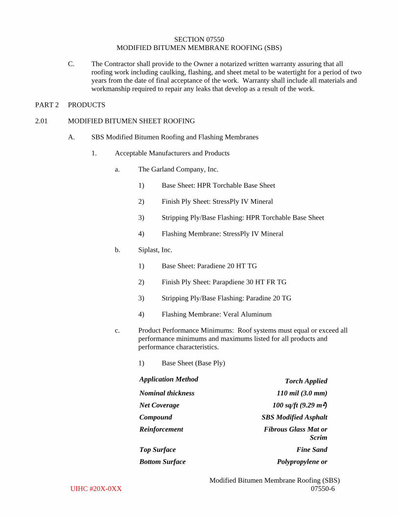
SECTION 07550 MODIFIED BITUMEN MEMBRANE ROOFING (SBS)
Modified Bitumen Membrane Roofing (SBS) UIHC #20X-0XX 07550-6
C. The Contractor shall provide to the Owner a notarized written warranty assuring that all roofing work including caulking, flashing, and sheet metal to be watertight for a period of two years from the date of final acceptance of the work. Warranty shall include all materials and workmanship required to repair any leaks that develop as a result of the work.
PART 2 PRODUCTS
2.01 MODIFIED BITUMEN SHEET ROOFING
A. SBS Modified Bitumen Roofing and Flashing Membranes
1. Acceptable Manufacturers and Products
a. The Garland Company, Inc.
1) Base Sheet: HPR Torchable Base Sheet
2) Finish Ply Sheet: StressPly IV Mineral
3) Stripping Ply/Base Flashing: HPR Torchable Base Sheet
4) Flashing Membrane: StressPly IV Mineral
b. Siplast, Inc.
1) Base Sheet: Paradiene 20 HT TG
2) Finish Ply Sheet: Parapdiene 30 HT FR TG
3) Stripping Ply/Base Flashing: Paradine 20 TG
4) Flashing Membrane: Veral Aluminum
c. Product Performance Minimums: Roof systems must equal or exceed allperformance minimums and maximums listed for all products andperformance characteristics.
1) Base Sheet (Base Ply)
Application Method Torch Applied
Nominal thickness 110 mil (3.0 mm)
Net Coverage 100 sq/ft (9.29 m²)
Compound SBS Modified Asphalt
Reinforcement Fibrous Glass Mat or Scrim
Top Surface Fine Sand
Bottom Surface Polypropylene or
November 1, 2016
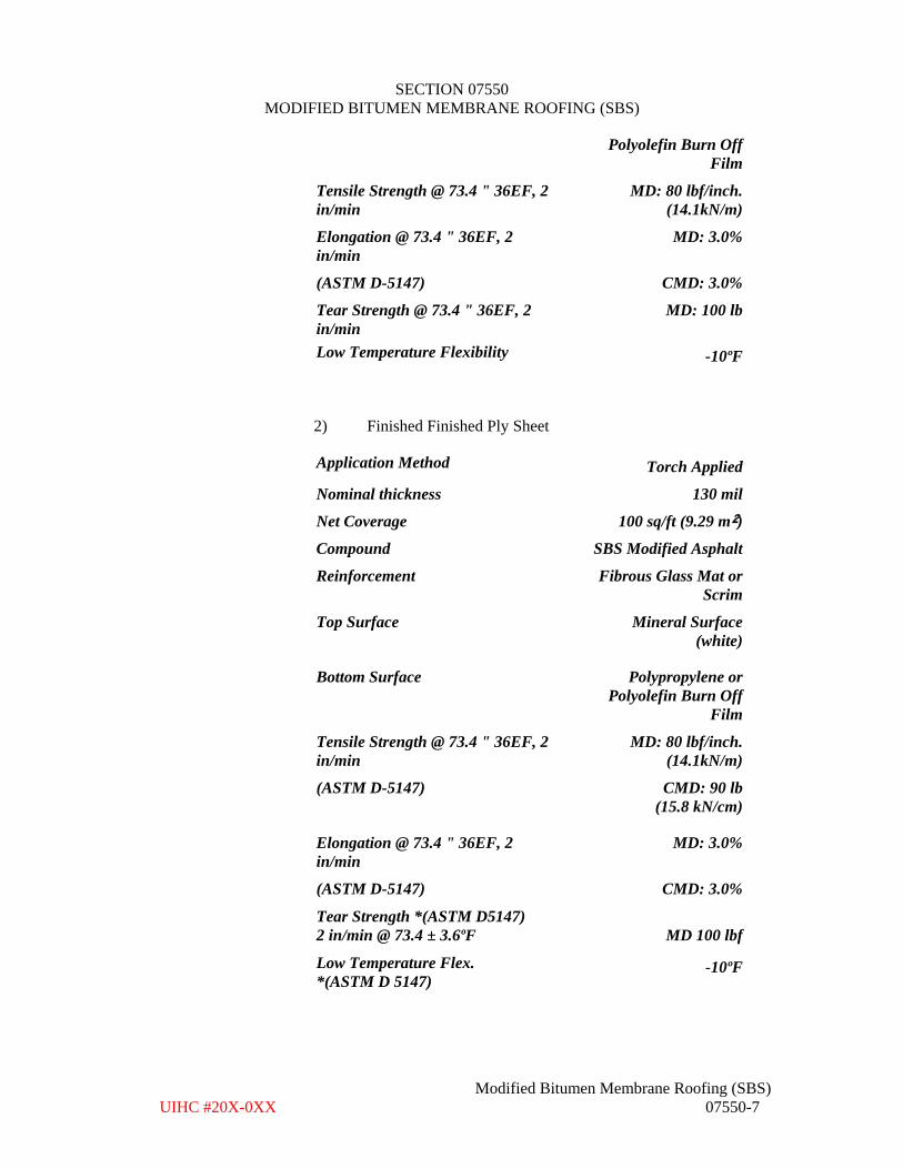
SECTION 07550 MODIFIED BITUMEN MEMBRANE ROOFING (SBS)
Modified Bitumen Membrane Roofing (SBS) UIHC #20X-0XX 07550-7
Polyolefin Burn Off Film
Tensile Strength @ 73.4 " 36EF, 2 n/min i
MD: 80 lbf/inch. (14.1kN/m)
Elongation @ 73.4 " 36EF, 2 in/min
MD: 3.0%
(ASTM D-5147) CMD: 3.0%
Tear Strength @ 73.4 " 36EF, 2 in/min
MD: 100 lb
Low Temperature Flexibility -10ºF
2) Finished Finished Ply Sheet
Application Method Torch Applied
Nominal thickness 130 mil
Net Coverage 100 sq/ft (9.29 m²)
Compound SBS Modified Asphalt
Reinforcement Fibrous Glass Mat or Scrim
Top Surface Mineral Surface (white)
Bottom Surface Polypropylene or Polyolefin Burn Off
Film
Tensile Strength @ 73.4 " 36EF, 2 in/min
MD: 80 lbf/inch. (14.1kN/m)
(ASTM D-5147) CMD: 90 lb (15.8 kN/cm)
Elongation @ 73.4 " 36EF, 2 n/min i
MD: 3.0%
(ASTM D-5147) CMD: 3.0%
Tear Strength *(ASTM D5147) 2 in/min @ 73.4 ± 3.6ºF MD 100 lbf
Low Temperature Flex. *(ASTM D 5147)
-10ºF
November 1, 2016
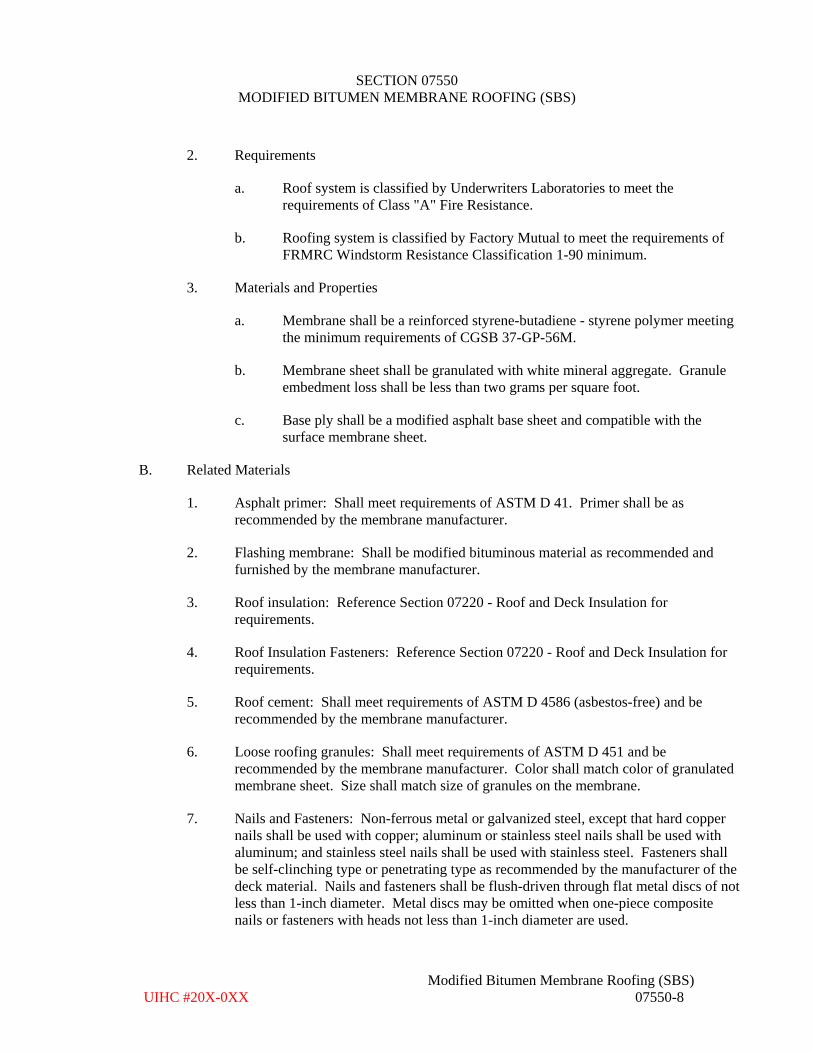
SECTION 07550 MODIFIED BITUMEN MEMBRANE ROOFING (SBS)
Modified Bitumen Membrane Roofing (SBS) UIHC #20X-0XX 07550-8
2. Requirements
a. Roof system is classified by Underwriters Laboratories to meet therequirements of Class "A" Fire Resistance.
b. Roofing system is classified by Factory Mutual to meet the requirements ofFRMRC Windstorm Resistance Classification 1-90 minimum.
3. Materials and Properties
a. Membrane shall be a reinforced styrene-butadiene - styrene polymer meetingthe minimum requirements of CGSB 37-GP-56M.
b. Membrane sheet shall be granulated with white mineral aggregate. Granuleembedment loss shall be less than two grams per square foot.
c. Base ply shall be a modified asphalt base sheet and compatible with thesurface membrane sheet.
B. Related Materials
1. Asphalt primer: Shall meet requirements of ASTM D 41. Primer shall be asrecommended by the membrane manufacturer.
2. Flashing membrane: Shall be modified bituminous material as recommended andfurnished by the membrane manufacturer.
3. Roof insulation: Reference Section 07220 - Roof and Deck Insulation forrequirements.
4. Roof Insulation Fasteners: Reference Section 07220 - Roof and Deck Insulation forrequirements.
5. Roof cement: Shall meet requirements of ASTM D 4586 (asbestos-free) and berecommended by the membrane manufacturer.
6. Loose roofing granules: Shall meet requirements of ASTM D 451 and berecommended by the membrane manufacturer. Color shall match color of granulatedmembrane sheet. Size shall match size of granules on the membrane.
7. Nails and Fasteners: Non-ferrous metal or galvanized steel, except that hard coppernails shall be used with copper; aluminum or stainless steel nails shall be used withaluminum; and stainless steel nails shall be used with stainless steel. Fasteners shallbe self-clinching type or penetrating type as recommended by the manufacturer of thedeck material. Nails and fasteners shall be flush-driven through flat metal discs of notless than 1-inch diameter. Metal discs may be omitted when one-piece compositenails or fasteners with heads not less than 1-inch diameter are used.
November 1, 2016
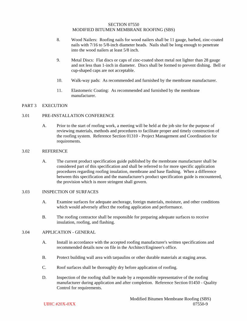
SECTION 07550 MODIFIED BITUMEN MEMBRANE ROOFING (SBS)
Modified Bitumen Membrane Roofing (SBS) UIHC #20X-0XX 07550-9
8. Wood Nailers: Roofing nails for wood nailers shall be 11 gauge, barbed, zinc-coatednails with 7/16 to 5/8-inch diameter heads. Nails shall be long enough to penetrateinto the wood nailers at least 5/8 inch.
9. Metal Discs: Flat discs or caps of zinc-coated sheet metal not lighter than 28 gaugeand not less than 1-inch in diameter. Discs shall be formed to prevent dishing. Bell orcup-shaped caps are not acceptable.
10. Walk-way pads: As recommended and furnished by the membrane manufacturer.
11. Elastomeric Coating: As recommended and furnished by the membranemanufacturer.
PART 3 EXECUTION
3.01 PRE-INSTALLATION CONFERENCE
A. Prior to the start of roofing work, a meeting will be held at the job site for the purpose of reviewing materials, methods and procedures to facilitate proper and timely construction of the roofing system. Reference Section 01310 - Project Management and Coordination for requirements.
3.02 REFERENCE
A. The current product specification guide published by the membrane manufacturer shall be considered part of this specification and shall be referred to for more specific application procedures regarding roofing insulation, membrane and base flashing. When a difference between this specification and the manufacturer's product specification guide is encountered, the provision which is more stringent shall govern.
3.03 INSPECTION OF SURFACES
A. Examine surfaces for adequate anchorage, foreign materials, moisture, and other conditions which would adversely affect the roofing application and performance.
B. The roofing contractor shall be responsible for preparing adequate surfaces to receive insulation, roofing, and flashing.
3.04 APPLICATION - GENERAL
A. Install in accordance with the accepted roofing manufacturer's written specifications and recommended details now on file in the Architect/Engineer's office.
B. Protect building wall area with tarpaulins or other durable materials at staging areas.
C. Roof surfaces shall be thoroughly dry before application of roofing.
D. Inspection of the roofing shall be made by a responsible representative of the roofing manufacturer during application and after completion. Reference Section 01450 - Quality Control for requirements.
November 1, 2016
SECTION 07550 MODIFIED BITUMEN MEMBRANE ROOFING (SBS)
Modified Bitumen Membrane Roofing (SBS) UIHC #20X-0XX 07550-10
E. Roofing insulation shall be dry when installed and shall be protected from the weather during installation. All materials which become wet shall be removed and replaced with new dry materials.
F. Membrane shall be installed over membrane manufacturer approved insulation. Install recovery board as required by the membrane manufacturer although details on the plan may not show it.
G. When application of roofing is begun, the total roofing system in that area shall be completed before the end of the day and before being wet by the elements. Phase construction may be done as approved by the manufacturer. Written approval from the membrane manufacturer is required for phase construction.
H. Install temporary water cutoffs at the completion of each day's work and remove upon resumption of the work. Any leaks and damage due to insufficient water cut-offs shall be repaired by the Contractor at no cost to the Owner.
I. Precautions shall be taken to protect the membrane from puncture.
J. If materials are stored on the roof, the materials will be protected from the existing roof.
K. Special care will be taken to prevent distress on the building structure when handling materials for the project.
L. Apply loose roofing granules in asphalt bleedout at side and end laps in accordance with membrane manufacturer's recommendations.
3.05 SEQUENCING/SCHEDULING
A. Notify the Owner and Architect/Engineer 48 hours before the first day of construction.
B. Install all base flashing and/or fascia system fasteners and metal work, at least throughout the anticipated working area, as soon as possible after roofing application.
C. Complete all specified carpentry and wood component installations, at least throughout the anticipated working area, as soon as possible after any roofing application.
D. Surfacing and installation of loose granules shall be completed within the time period as recommended by the membrane manufacturer.
3.06 PREPARATION
A. Priming of Surfaces.
1. Prime flanges of metal gravel stops, edging strips, flashing collars and accessories asrecommended by manufacturer prior to stripping into the roofing system.
B. Prime concrete and gypsum decks, and masonry walls with primer for adherence of asphalt bitumen. Follow manufacturer's recommendations for application.
November 1, 2016
SECTION 07550 MODIFIED BITUMEN MEMBRANE ROOFING (SBS)
Modified Bitumen Membrane Roofing (SBS) UIHC #20X-0XX 07550-11
3.07 APPLICATION OF MODIFIED BITUMEN SHEET (REROOFING)
A. Apply base ply over substrate as recommended by the membrane manufacturer. Reference Section 07220 - Roof and Deck Insulation for installation requirements of roof insulation. Apply bitumen at the coverage rate and temperature as recommended by the manufacturer.
B. Phased application is not permitted. All plies shall be completed each day.
C. Application of base ply should result in a smooth even substrate in order to firmly bond membrane onto.
D. Align base plies so manufacturer's minimum specified end and side laps are maintained.
E. When base ply has laying lines, the lines shall be used to position the subsequent plies for compliance with nominal lap requirement. For products without laying lines, conform to manufacturer's lap requirement.
F. Should misalignment of the sheet occur during application causing a variation from minimum lap requirements, the sheet should be cut and realigned to satisfy minimum lap requirements.
G. Clean and prepare base-ply for application of finish-ply membrane.
H. Apply finish-ply membrane over base-ply as recommended by the membrane manufacturer.
I. All layers of roofing shall be laid free of wrinkles, creases or fishmouths and shall be laid at right angles to the slope of the deck so the direction of flow of water is over and not against the laps.
J. Sheets shall be laid directly behind the torch applicator.
K. Sufficient pressure shall be exerted as recommended by the membrane manufacturer on the roll during application to ensure prevention of air pockets, and proper embedment.
L. Lap base ply and surface membrane the minimum distance as recommended by the membrane manufacturer.
M. Stagger laps between the plies so the base-ply lap is not within two inches of the finish-ply membrane lap.
N. During inspection if there is insufficient lap width, a membrane strip no narrower than twice that of the required lap shall be installed over the deficient lap using the appropriate attachment method.
O. Torching
1. Follow the owners requirements for fire safety and permitting system. See Section00441.
November 1, 2016
SECTION 07550 MODIFIED BITUMEN MEMBRANE ROOFING (SBS)
Modified Bitumen Membrane Roofing (SBS) UIHC #20X-0XX 07550-12
2. Torch-apply to substrate by heating bitumen by heating membrane in accordance withmanufacturer’s recommendations. Applications between membrane plies shall besuch as to produce voidless coverage. Embed plies in the bitumen.
3. Do not walk on plies on plies while the bitumen is still fluid.
4. Asphalt flow of a minimum ¼ inch beyond lap line shall result during application.Apply loose granules in asphalt flow immediately to ensure proper embedment. Rolllap with a 20# steel roller. Roller shall not be more than 5 feet behind torch duringwelding process.
5. The completed roof system shall be free of voids of blisters.
6. Defects in the application such as voids, fishmouths, physical damage, loose or drylaps, non-approved materials, etc. shall be repaired by the Contractor asrecommendedby the membrane manufacturer at no cost to the Owner.
3.08 APPLICATION OF MODIFIED BITUMEN FLASHING MEMBRANE (REROOFING)
A. Provide modified bitumen flashing in the angles formed where the roof deck abuts walls, curbs, ventilators, pipes and other vertical surfaces, and where necessary to make the work watertight. Modified bitumen flashings are as recommended and provided by the membrane manufacturer.
B. Apply one-ply of modified bitumen base-ply and one ply of modified bitumen finish-ply membrane at all flashing locations. Apply in accordance with manufacturer's installation instructions. Apply flashing by method (torch applied) as recommended by the membrane manufacturer.
C. Install flashing in accordance with the details shown on the plans or with the manufacturer's published standards whichever is more stringent.
D. All perimeter flashings shall conform to Factory Mutual (FM) Loss Prevention Data Sheet 1-49.
E. Side and end laps shall be overlapped a minimum of 4". All flashings shall extend a minimum of 6" onto the field of the roof. Selvage edge of membrane shall not be exposed.
F. Flashing membrane should not be stretched when applied.
G. All curbs and walls shall have cants.
H. Curb and parapet flashings shall be fastened at top at 6" oc. with 1" diameter cap nails.
I. All flashing materials shall be 100% bonded to walls, curbs, edges, and other surfaces being flashing.
J. All raised flashings shall be a minimum of eight (8) inches above the surface of the finished roof surface.
November 1, 2016
SECTION 07550 MODIFIED BITUMEN MEMBRANE ROOFING (SBS)
Modified Bitumen Membrane Roofing (SBS) UIHC #20X-0XX 07550-13
K. All raised flashings shall have a counterflashing.
L. All metal, masonry, and concrete in contact with flashing shall be primed and allowed to dry. No metal flashing shall be set in hot bitumen.
M. A layer of roof cement shall be used to separate any membrane from contact with sheet metal flashing elements.
N. Bed set-on accessories in a thick coating of roof cement extending under entire metal flange of each accessory item.
O. Roof Drains:
These specifications apply for installation of cast iron drains only. For all other drain types follow membrane manufacturer's recommendations.
1. Roofing contractor shall be responsible for modifying existing drain assemblies fornew roof installation, including, but not limited to, lowering drain assembly,modifying leaders, etc. so that there is positive drainage of water around drain.
2. Remove existing flashings (including lead flashings if applicable), roofing material,and cement in preparation for new membrane flashing.
3. Provide a clean even finish on the mating surfaces between the clamping ring and thedrain bowl.
4. Membrane plies, metal flashings, and flash-in plies shall extend under clamping ring.
5. Install new lead flashing, see Section 07620. Prime lead as required.
6. Install flashing membrane plies as recommended by membrane manufacturer.Flashing plies shall extend a minimum of 4" beyond edge of lead flashing, but notbeyond edge of sump.
7. Install the roof drain clamping ring and clamping bolts. Tighten the clamping bolts toachieve constant and uniform compression. Replace any damaged, broken, or missingclamping rings or with new to match existing drain design. Replace all claming ringbolts with new. New bolts shall be brass or stainless steel. Drill and tap broken drainbolts as required for installation or replacement bolts.
8. Replace any damaged, broken, or missing drain grates with new. New grates shall bemetal.
9. Seal between the membrane and the drain base shall be watertight.
10. Prevent bitumen drippage into drain leader.
11. Roof drain is to be checked and made operational at the conclusion of the roofconstruction activities.
November 1, 2016
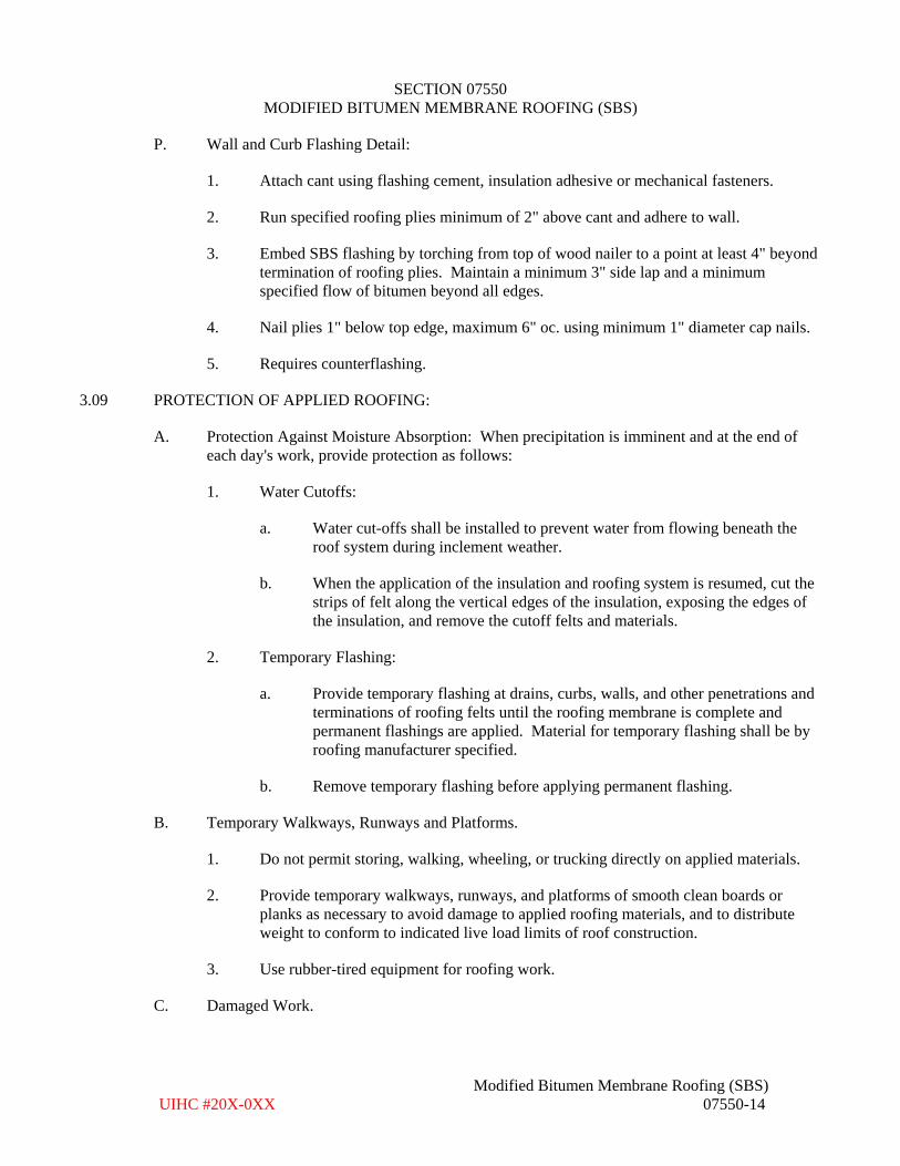
SECTION 07550 MODIFIED BITUMEN MEMBRANE ROOFING (SBS)
Modified Bitumen Membrane Roofing (SBS) UIHC #20X-0XX 07550-14
P. Wall and Curb Flashing Detail:
1. Attach cant using flashing cement, insulation adhesive or mechanical fasteners.
2. Run specified roofing plies minimum of 2" above cant and adhere to wall.
3. Embed SBS flashing by torching from top of wood nailer to a point at least 4" beyondtermination of roofing plies. Maintain a minimum 3" side lap and a minimumspecified flow of bitumen beyond all edges.
4. Nail plies 1" below top edge, maximum 6" oc. using minimum 1" diameter cap nails.
5. Requires counterflashing.
3.09 PROTECTION OF APPLIED ROOFING:
A. Protection Against Moisture Absorption: When precipitation is imminent and at the end of each day's work, provide protection as follows:
1. Water Cutoffs:
a. Water cut-offs shall be installed to prevent water from flowing beneath theroof system during inclement weather.
b. When the application of the insulation and roofing system is resumed, cut thestrips of felt along the vertical edges of the insulation, exposing the edges ofthe insulation, and remove the cutoff felts and materials.
2. Temporary Flashing:
a. Provide temporary flashing at drains, curbs, walls, and other penetrations andterminations of roofing felts until the roofing membrane is complete andpermanent flashings are applied. Material for temporary flashing shall be byroofing manufacturer specified.
b. Remove temporary flashing before applying permanent flashing.
B. Temporary Walkways, Runways and Platforms.
1. Do not permit storing, walking, wheeling, or trucking directly on applied materials.
2. Provide temporary walkways, runways, and platforms of smooth clean boards orplanks as necessary to avoid damage to applied roofing materials, and to distributeweight to conform to indicated live load limits of roof construction.
3. Use rubber-tired equipment for roofing work.
C. Damaged Work.
November 1, 2016
SECTION 07550 MODIFIED BITUMEN MEMBRANE ROOFING (SBS)
Modified Bitumen Membrane Roofing (SBS) 07550-15 UIHC #20X-0XX
1. Restore work damaged during construction to original condition or replace with newmaterials.
3.10 SHEET METAL WORK (REFERENCE SECTION 07620)
A. Counterflashings, copings and other perimeter or penetration metal work shall be properly fastened and sealed by the roofing contractor or others, and it shall be their responsibility to maintain this work in a watertight condition. Care should be taken to assure the membrane is not in contact with sharp edges and is not unsupported in an area greater than 1/4-inch.
3.11 MANUFACTURER'S WARRANTY INSPECTIONS
A. Inspections shall be as noted below.
B. Manufacturer’s shall include three full days of construction observation during the construction process.
1. Written reports of these visits shall be provided to the Architect/Engineer and theOwner.
2. The A/E shall be notified a minimum of 48 hours in advance of such visits.
C. After the work has started and within the first five working days, an inspection shall be made by a field technical representative of the membrane manufacturer. The representative shall review materials, methods, and procedure to facilitate proper and timely construction of the roofing system. Upon completion of the inspection the Contractor shall submit the Engineer/Architect a written report of the field technical representative’s findings.
D. At approximately 50% completion of construction, an inspection shall be made by a field technical representative of the membrane manufacturer. The representative shall review materials, methods, and procedure to facilitate proper and timely construction of the roofing system. Upon completion of the inspection the Contractor shall submit the Engineer/Architect a written report of the field technical representative’s findings.
E. Upon completion of the installation, an inspection shall be made by a field technical representative of the membrane manufacturer to ascertain that the roofing system has been installed according to the manufacturer's current published specifications. Upon completion of the inspection, the Contractor shall submit to an Architect/Engineer a written report of the field technical representative's findings.
November 1, 2016

ROOF MAINTENANCE WARRANTY
PROJECT: 206104-0 UIHC Project No. 205-039
This agreement between ____________________________________, hereinafter referred to as OWNER, and _______________________________, hereafter referred to as CONTRACTOR, is entered into to provide maintenance on the roof of __________________, located at _____________________, _______________, Iowa, for ____ years beginning _________________, 20___ and ending ________________, 20___.
For the purpose of this agreement, maintenance is defined as the repair of roof membrane and flashing defects, and the replacement of roof membrane and flashing components that threaten the viability of the roof system to keep the building free from externally caused leakage through the roof. Warranty shall include all materials and workmanship required to repair any defects that develop during the warranty period at no expense to the OWNER.
Specifically excluded from the responsibility of the CONTRACTOR under the terms of this agreement are any and all damages to said roof, the building or contents caused by the acts or omissions of other trades or contractors; lightning, winds in excess of a strong gale as defined by the Beaufort scale, hailstorm, flood, earthquake or other unusual phenomena of the elements.
The component parts of this agreement are:
1. A yearly comprehensive inspection of the roof during which time all defects that need to be repaired and allcomponents that need to be replaced will be identified by the inspector.
2. Should defects be found during inspection that are not covered by this agreement, the CONTRACTOR will notifythe OWNER in writing as to the cause (who or what was responsible), and the estimate of the cost to return theroof to its condition before the problem occurred. Written approval to proceed with the work must be granted bythe OWNER.
3. Completion of all repairs and replacement in a manner consistent with the highest standards of the roofingindustry. Work shall be in compliance with the membrane manufacturer's written specifications and warranty, soas not to void warranty.
4. A follow-up inspection of the completed maintenance work.
5. Response within 24 hours of all requests for repair of leaks or other emergencies that are part of this agreement.
6. This maintenance warranty covers CAULKING for the listed project and shall be included along with the roofingwarranty. The undersigned CONTRACTOR will repair or replace defective caulking work and other workdamaged thereby during the warranty period at no expense to the OWNER. The following type of failures areconsidered defects: Leakage, hardening, cracking, crumbling, melting, shrinkage, running or staining adjacentwork.
7. This maintenance warranty covers FLASHING for the listed project and shall be included along with the roofingwarranty.
8. This maintenance warranty covers SHEETMETAL for the listed project and shall be included along with theroofing warranty.
OWNER: CONTRACTOR:
____________________________________ __________________________________________Name Name
____________________________________ __________________________________________Title Title
November 1, 2016
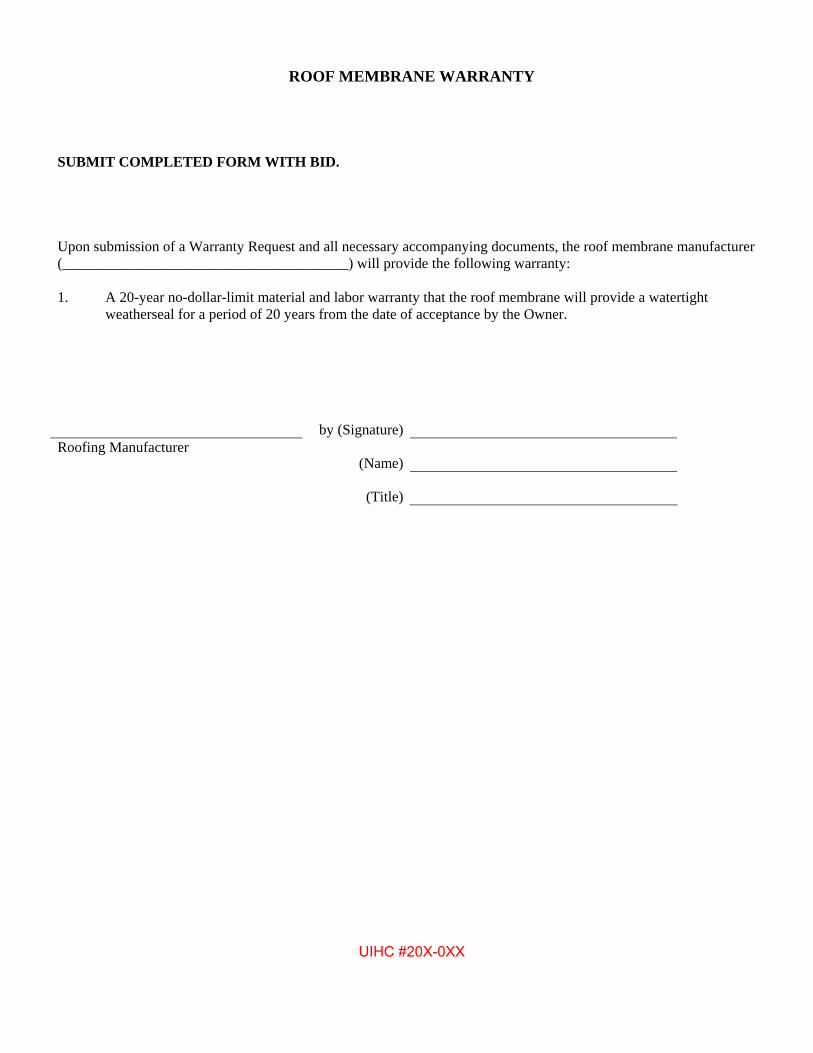
ROOF MEMBRANE WARRANTY
SUBMIT COMPLETED FORM WITH BID.
Upon submission of a Warranty Request and all necessary accompanying documents, the roof membrane manufacturer (_______________________________________) will provide the following warranty:
1. A 20-year no-dollar-limit material and labor warranty that the roof membrane will provide a watertightweatherseal for a period of 20 years from the date of acceptance by the Owner.
by (Signature)Roofing Manufacturer
(Name)
(Title)
UIHC #20X-0XX
November 1, 2016
SECTION 07550 MODIFIED BITUMEN MEMBRANE ROOFING (SBS)
Modified Bitumen Roofing Membrane (SBS) 07550-18 UIHC #20X-0XX
END OF SECTION
November 1, 2016
Appendix G
UIHC Pneumatic Tube System (Section 14 92 00)
November 1, 2016
SECTION 14 92 00 November 1, 2016
HOSPITAL WIDE PNEUMATIC TUBE SYSTEM
149200-1
UIHC # THE UNIVERSITY OF IOWA HOSPITALS AND CLINICS POST BID CON. DOC.:
TITLE OF PROJECT HERE
20X-XXX DATE
PART 1 - GENERAL
1.1 SUMMARY
A. Section includes: 1. Extension of existing Swisslog CTS 630 Computerized Pneumatic Tube System (Computer controlled,
single tube system with six-inch round carriers) with a new branch (zone) to the [station location and type here], the University of Iowa Hospitals and Clinics.
2. Pneumatic tube station (equipment number 14 92 00) in the following locations:a. [Insert location(s) here]
1.2 APPROVAL
A. Submit three copies of the manufacturer's proposed system extension layout and functioning description by 2 weeks prior to bid date for approval by the Hospital's representative, Mr. Merle Hagie, prior to submitting pneumatic tube extension quotation to the Bidders.
1.3 SYSTEM RESPONSIBILITY AND TESTING
A. System responsibility as follows: 1. It is intended that the existing pneumatic tube system shall be extended with a new branch / zone to the
[insert location here] by SWISSLOG HEALTHCARE SOLUTIONS (800-821-3483; ext. 206) or Owner approved equal.
2. Contractor will be responsible for all coordination necessary for SWISSLOG HEALTHCARESOLUTIONS to provide the computer programming for additions to the existing system.
B. The existing pneumatic tube system shall be maintained in full operation. All required switchgear down-time for the existing system shall be scheduled with the Hospital for being done after normal working hours at no additional cost to the Owner.
C. All wall penetrations for pneumatic tube system will be responsibility of this Section. Fire walls shall have required rating firestopping packed in penetrations and all exposed surfaces properly sealed and finished.
D. The complete extended system including the portion currently installed, shall be tested by the manufacturer's installer for seven consecutive days in continuous operation with not more than one failure per 1,000 transactions prior to Owner acceptance. This shall include all failures or defects of all kind except those due to user error and system misuse. Non-compliance with these specifications and system malfunctions shall be corrected per manufacturer's instructions to operate per these specifications and manufacturer's printed product information.
1.4 SUBMITTALS
A. Shop Drawings shall indicate routing of tubing; space required for tubing, transfer units, storage units, stations and other pertinent components; location, capacity, horsepower and space requirements of blowers, descriptions and space requirements of central control center; detailed drawings of accessory components of system; diagrams of completed wire system; and epidemiological controls per Section 01515.
PART 2 - MATERIALS
2.1 PERFORMANCE AND QUALITY
A. System shall be standard product of domestic manufacturer.
SECTION 14 92 00 November 1, 2016
HOSPITAL WIDE PNEUMATIC TUBE SYSTEM
149200-2
UIHC # THE UNIVERSITY OF IOWA HOSPITALS AND CLINICS POST BID CON. DOC.:
TITLE OF PROJECT HERE
20X-XXX DATE
f. Individual branch on/off switch.
B. System shall be computer controlled pressure-vacuum pneumatic tube network of nominal 6" size, designed for transport of documents, x-rays, I.V. containers, laboratory samples, pharmaceuticals, and small supplies. System shall be fully automatic requiring no intermediate handling of carriers once inserted and receiving address accepted by system.
C. Carrier transactions shall take shortest route to destination avoiding superfluous travel. Carrier shall not be required to travel to central location for destination routing.
D. Carriers shall be dispatched from system by vacuum and pressure delivered. System shall present tubing dimensioned equipment to carrier through all travel areas within air stream - from dispatch to delivery. Expanded bends, Y-branches are not permitted. Impact operated devices are not desirable.
E. System characteristics shall ensure carrier is handled in gentle, controlled manner so sensitive materials and laboratory samples can be transported without damage.
F. System shall be computer controlled and supervised. A master interface panel shall be provided to permit convenient communications with system for maintenance and management.
G. Transfer from one operational section of system to another shall be through above-ceiling mounted transfer units in minimal time periods.
H. System shall be based on eleven thousand carrier transactions per 24 hour day with peak system performance of 1,650 carrier transactions per hour for two hours each twenty-four hour day when future expansion is completed. System Supplier shall take into account selective station slowdown if capability is available. Selective station slowdown transactions will represent approximately twenty percent of total daily transactions. Transaction capacity and system configuration upon completion of ultimate expansion will be determined as specified in paragraph 1.2 A.
2.2 SYSTEM CONTROL
A. System control shall be by mini-computer system controlling and supervising transactions from dispatch addressing to delivery at receiving station with provision of fault location, maintenance diagnosis and data output for management control. System control shall include the following: 1. Supervise and control all sending and receiving transactions and provide selective monitoring, on
demand, of each dispatch through entire transaction route. 2. Provide fault alarm in event of malfunction and visually display fault location and nature of fault.3. Standard commercial Mini-computer, magnetic core memory, software programmable or compatible
with existing system computer.4. Computer-operated Interface Panel which provides the following inter-action capability:
a. Display module to verify address of each system device and confirm nature and location ofsystem faults.
b. Keyboard for addressing and exercising all devices within system. Supplier shall providedescription of keyboard with bid submittal.
c. Monitoring of each dispatch through entire transaction route and memory function to re-traceroute in event of delivery failure.
d. Carrier dispatch backlog indicator on master control.e. System transaction counter and resettable individual branch counter.
g. Plug-in circuit boards.h. CRT add-on capabilities.i. System voltage level display on Master Control.j. Blower mode indicator.k. Disabling key switch for keyboard operation (off-operate-exercise) on Master Control.
SECTION 14 92 00
November 1, 2016
HOSPITAL WIDE PNEUMATIC TUBE SYSTEM
149200-3
UIHC # THE UNIVERSITY OF IOWA HOSPITALS AND CLINICS POST BID CON. DOC.:
TITLE OF PROJECT HERE
20X-XXX DATE
5. Operational or process programs shall control and supervise transactions and operations of all systemdevices. No sending transactions will be permitted unless transaction route and receive station checkclear. Carrier shall return to sending station if unable to transact route to addressed station.
6. Supplier shall describe in detail, the intra-system communications with submittal.7. Expansion of system computer shall require minimum or no hardware addition or modification. If
modification is required, Supplier shall delineate.8. Printed circuit boards within system shall be standardized to minimize inventory needs. Supplier shall
describe fault locating diagnostic procedure with submittal.9. Station and diverter control logic shall incorporate semi-conductors to minimize power consumption
and reduce noise.
2.3 STATIONS
A. Stations shall be designed for up send only. Operating mechanisms shall be fully accessible for servicing from front.
B. Station fronts shall be free of sharp edges and corners and fabricated from materials not easily abraded through extended use and cleaning.
C. Stations shall be completely insertable or removable as a unit into recessed frame. Station control boards shall have the following features: 1. Lighted display to validate selected address and clear route before executing of send instruction by
operator. 2. Indicator light for carrier arrival, full sender, station on, carrier enroute and flashing light and audible
signal for full receiver.
D. Stations shall include optional RFID reader.
E. Supplier shall specify and describe all modifications and alterations to station controls to accommodate system expansion. Stations shall have plug-in terminations for power and communications cabling.
F. Stations shall have printed circuit board design.
G. Positioning or carrier present sensors shall be described with submittal.
H. Stations shall be capable of holding one carrier in send magazine, addressed and ready for dispatch under computer supervision without further operator intervention.
I. Supplier shall describe power supply and distribution into system.
J. Stations shall be capable of accepting system expansion with minimal modifications and alteration of installed controls and equipment. Modification and alteration shall be described.
K. Touch pad style station sign-off shall be provided.
L. Optional colors for finish shall be provided.
M. Automatic empty carrier return shall be provided.
2.4 DIVERTERS
A. Supplier shall describe in detail complete operation and operating characteristics of diverters with submittal.
SECTION 14 92 00
November 1, 2016
HOSPITAL WIDE PNEUMATIC TUBE SYSTEM
149200-4
UIHC # THE UNIVERSITY OF IOWA HOSPITALS AND CLINICS POST BID CON. DOC.:
TITLE OF PROJECT HERE
20X-XXX DATE
B. Supplier shall submit diverter specifications, which include dimensions, weight, maintenance program, whether unit can be in-house repaired (assuming worst likely problem), and any other pertinent data with submittal.
C. Diverter controls shall be incorporated in single printed circuit board with provisions for present and future power and signal terminations.
D. Diverters shall utilize a chain drive mechanism if possible rather than cable drive mechanism.
2.5 CARRIERS
A. Six Eco-Seal carriers shall be furnished for each station. Eco-Seal carrier inserts shall be provided as follows and in quantities determined by the Owner: 1. Container for transporting filled vacutainers. Construction shall be described. Insert shall
accommodate supplier specified number of vacutainers. 2. Universal type for transporting miscellaneous medications and fragile items. Construction shall be
described by Supplier, split, and readily installed and removed from carrier. Inserts shall have capacity to accommodate minimum load of 500 milliliter I.V. container.
3. I.V. type for transporting one thousand milliliter plastic I.V. containers. Construction shall be describedby Supplier, split and readily installed and removed from carrier.
4. X-Ray type for transporting fourteen inch by seventeen inch films without folds and damage. Insertsshall be padded on both sides to prevent scratching of films. Describe with submittal.
5. Carrier volume shall be minimum 230 cubic inches.
B. Carriers shall have the following characteristics: 1. Clear construction, Eco-Seal type2. Not acceptable in system unless positively closed.3. Bi-directional.4. Cannot open in transit.5. Riding rings which are easily replaceable in house.6. Durable construction.7. Contain RFID chips.
2.6 INTER-BRANCH TRANSFER
A. Carriers shall be transferred between branches through interaction of diverters and exhausters under computer control and supervision.
B. Describe inter-branch transfer equipment space requirements.
C. Installation frames shall be provided for inter-branch diverters to avoid installation of operating equipment during construction phases.
D. Inter-branch transfer system shall have ability to transfer more than one carrier among branches simultaneously. As additional branches are added to the system, capability of simultaneous transfer of multiple carriers between branches shall increase.
2.7 LINE MATERIAL
A. Tubing shall be minimum sixteen gage electrical welded steel, galvanized and specifically fabricated for pneumatic tube applications. Bends shall be same material formed on center line radius of minimum 48".
B. Hangers and supports shall be spaced on no more than 10'-0" centers and within 1 foot of offsets (joints). Ceiling hung type shall be from concrete decks only. Bends and straight runs and rises shall be hung or supported to minimize noise and deflection in system from normal carrier passing.
SECTION 14 92 00
November 1, 2016
HOSPITAL WIDE PNEUMATIC TUBE SYSTEM
149200-5
UIHC # THE UNIVERSITY OF IOWA HOSPITALS AND CLINICS POST BID CON. DOC.:
TITLE OF PROJECT HERE
20X-XXX DATE
C. Tube ends shall be joined by either drive sleeves or a bolted coupling. Bolted sleeves shall be used at joint to major components.
D. All tubing runs through areas determined to be noise sensitive shall be insulted with sound insulating glass fiber at least 1½" one pound density type with Aluminum foil backing.
2.8 POWER SUPPLY AND DISTRIBUTION
A. Power, control wiring and conduit required shall be provided by pneumatic tube manufacturer, except primary power source for main control and blowers only.
B. Power and control wiring shall be installed in steel conduit. 1. 1” conduit for 50 conductor com cable,2. ¾” conduit for power cable 1 red, 1 black, 10 gauge cable,3. ¾” conduit for critical care system (4 twisted pair).
C. System power shall be turned on and off and distributed and monitored by master control unit.
D. System design shall facilitate connection of emergency power at minimum number of locations to provide continuous operation of entire system on emergency power. System supplier shall list connections to emergency power and describe in detail.
2.9 BLOWER PACKAGE
A. One exhauster package shall be installed for each branch. It shall provide motivating force to transport carrier within transmission tubing. 1. Package shall be capable of delivering either vacuum or pressured air to transmission tubing. It shall be
automatically controlled from Master Control. 2. Exhauster unit shall be complete with air sensing devices and valves for controlling air flow and solid
state control logic for interfacing with Master Control Unit. 3. Unit shall have sufficient capability (minimum 550 cfm) to move loaded carrier minimum twenty and
maximum twenty-five per second through designed length of system except when selective slowdown is in operation. Deviation of supplier's system from this shall be described; and qualitative and quantitative information shall be given to substantiate deviation with submittal.
4. Exhauster shall automatically shut down during periods of low activity and shall re-start automaticallywhen sending instruction is executed at station.
B. The blower noise shall not exceed 85 decibels.
C. Blower shall be 10 horsepower Swisslog provided regenerative blower.
D. Submit a complete and detailed description of blower package.
2.10 TRAINING
A. Maintenance and operating personnel shall be instructed in-house on use, maintenance and operation of system during final seven days of installation.
2.11 INSTRUCTION MANUALS
A. Upon completion of installation of system, Contractor shall furnish three copies of Instruction Manual and Maintenance Manual including the following: 1. Complete operating, trouble-shooting and preventive maintenance routines.2. Detailed spare parts list.
SECTION 14 92 00
November 1, 2016
HOSPITAL WIDE PNEUMATIC TUBE SYSTEM
149200-6
UIHC # THE UNIVERSITY OF IOWA HOSPITALS AND CLINICS POST BID CON. DOC.:
TITLE OF PROJECT HERE
20X-XXX DATE
3. Electrical schematics.4. Mechanical riser diagram and electrical wiring diagram.5. The computer program documentation.
2.12 ADDITIONAL FEATURES
A. Features shall be designed to permit incorporation into system with minimum alteration or modification to existing equipment or controls. 1. Each station shall accept two or more carriers, addressed and available for automatic dispatch under
computer control without further operation intervention. 2. System control shall be equipped for CRT Terminal which is complete with system programs that
provide maintenance diagnostic routines and management reports for systems maintenance and management purposes.
3. System controls shall incorporate carrier speed control capability that upon command from sendingstation, automatically transports selective carriers through entire transit route at pre-determined (12'-0" to 15'-0" per second) reduced rate of speed. Balance of system shall continue to operate at normal speed. Selected transit route shall return to normal speed upon completion of reduced velocity transaction. Pneumatic tube system shall be pre-set to designated transit routes to meet specific requirements of the Owner. This feature will include in selective speed control network those stations designated by the Owner.
4. Optical sensors for computer and diverters.5. Single touch addressing for high use stations.6. L.E.D.'s on printed circuit boards.
PART 3 - EXECUTION
3.1 INSTALLATION
A. Installation of system shall be in accordance with manufacturer's written instructions.
B. Station operating mechanism shall not be installed until system is ready for check-out to insure latest equipment models. Should improvements have been made on system components bid on, the Owner shall negotiate price differentials, if any, upon submission by manufacturer of complete description of improvements.
C. Provide protection for system components against damage.
D. Position diverters in ceiling spaces or shaft areas. Divertors shall be positioned so that at least 6" of clear space is above divertor components; at least 24" of clear un-obstructed space is available on the side of the divertor (full length) with the electrical panel; at least 6" of clear space is available in front of the divertor motor assembly; and at least 6" of clear space is available under the divertor motor assembly. In addition - un-obstructed access space in ceiling is required for maintenance access from below the ceiling to work on the divertor components..
E. After award of contract and prior to commencement of field work, manufacturer shall submit to the Owner a complete traffic flow analysis.
F. Installation of the pneumatic tube system shall be coordinated with other utilities installed above the ceilings. This section shall assist the Contractor in the preparation of the coordination drawings by providing the Contractor with drawings and equipment cuts of the pneumatic tube system.
SECTION 14 92 00
November 1, 2016
HOSPITAL WIDE PNEUMATIC TUBE SYSTEM
149200-7
UIHC # THE UNIVERSITY OF IOWA HOSPITALS AND CLINICS POST BID CON. DOC.:
TITLE OF PROJECT HERE
20X-XXX DATE
3.2 GUARANTEE
A. Pneumatic tube manufacturer shall guarantee in writing that at no charge during the twelve months after the Owner acceptance, manufacturer shall repair or replace system components causing system malfunction not due to ordinary wear and tear.
B. A twelve month preventive maintenance service agreement shall be available on a year to year contract basis. Supplier shall describe standard maintenance service agreement in submittal.
C. Service personnel for entire system and components, except computer, shall be full time employees of manufacturer, specifically trained for both routine and emergency servicing. Service response time shall be sufficient to insure reasonable system availability and reliability.
D. Service personnel for computer shall be employed by system manufacturer, specifically trained in maintenance, repair and programming of computer hardware and software, on emergency and routine basis. Service response time shall be sufficient to insure reasonable system availability and reliability.
********************END OF SECTION 14700

Appendix H
UI Emergency Generator Specifications
November 1, 2016
APPENDIX H
University of Iowa
Emergency Generator Specifications
The intent of these specifications is to establish a level of quality and desired function of the equipment specified that can be met by various suppliers. The equipment includes a single 1200 rpm or 1800 rpm diesel engine-generator set having a capacity of not less than 965 kW, associated remote radiators for cooling purposes, control panel and electrical distribution switchboard.
These specifications include furnishing a continuously rated, for standby use, diesel engine-generator set delivered to the site (University of Iowa Hospitals & Clinics (UIHC), Iowa City, IA) complete with all necessary accessories as may be hereinafter set forth. The term “continuously rated for standby use” shall mean that the set will be for standby service but once started shall be capable of carrying a full load on a continuous basis for an indefinite period of time. Unloading and setting of the set shall be part of a separate contract.
UIHC reserves the right to reject any or all bids where in their opinion the equipment offered does not meet the functional requirements of this installation. The University reserves the right to accept any bid where, in their opinion, the equipment offered meets the functional requirements of this installation, whether or not the equipment offered meets the technical specifications. UIHC shall be the sole judge in making this determination.
The equipment as specified shall be included in a proposal as a lump sum amount and shall be known as Base Bid. Where items are indicated as Alternates to the Base Bid, separate prices shall be indicated on the proposal as additions to or deductions from the Base Bid amount.
A. Engine-Generator
The engine-generator set shall be the product of a United States of American manufacturer, regularly engaged in the manufacture of generator plants. The set and controls shall be built and tested by the engine manufacturer precluding divided responsibility. The set shall be tested by the manufacturer of the set, as hereinafter specified in paragraph 4. Certified test reports of the complete assembly shall be available from the engine manufacturer showing the plant’s power rating, voltage and frequency regulation, and other pertinent data.
1. Rating
The continuously rated for standby use output of the set shall mean the set’s full continuous derated output under the climatic conditions shown below.
The single diesel engine shall be derated for the following ambient conditions:
• Altitude: 750 feet above sea level
1
November 1, 2016
• Engine Room Temperature: 120° F
Detailed capacity requirements shall be as set forth in paragraph 5.
2. Diesel Engine – Generator Set and Associated Apparatus
a. Engine Features
The diesel engine shall be heavy duty, compression ignition, water cooled, multi-cylinder, 2 stroke or 4 stroke, designed for cold quick start, capable of delivering fullload output in not more than ten seconds. Speed may be either 1200 rpm or 1800 rpm.
The engine shall have replaceable cylinder liners of the wet sleeve type, andreplaceable valve seat inserts. Exhaust manifolds shall be water cooled.
b. Starting System
The engine starting shall be by means of 24 volt starting motors. Crank terminationswitch shall be provided. Batteries of sufficient capacity for five, 15-secondconsecutive crank periods shall be furnished. The battery voltage shall be 24 volt DC.Batteries shall be lead-acid type. Battery charger with sufficiently high charge rateshall be furnished. 115 volt AC power shall be available for the battery charger. Abattery rack shall be furnished.
As an alternate to the Base Bid, the vendor shall provide a compressed air startingsystem in lieu of the electric start system. The compressed air starting system shallinclude:
1) Air starting motor.
2) Electric driven air compressor of adequate capacity.
3) Two air storage tanks (one reserve), each capable of giving not less than twostarting cycles.
4) Necessary controls to maintain the air storage tanks full and permit automaticstarting.
5) All associated and auxiliary compressed air piping required.
c. Cooling System
The cooling system shall insure that the maximum cooling water temperature is safelywithin the normal working temperature range when the set is operating continuously atfull load at maximum ambient temperature when the air intake temperature of theengine room may rise to 120° F. The engine outlet water temperature under suchconditions shall not exceed 200° F.
2
November 1, 2016
Cooling shall be provided by a remotely installed radiator unit of the vertical discharge style.
d. Lubrication System
A pressure type lubricating system with gear type oil pump and a full flow filter shallbe fitted to the engine.
e. Filters
Replacement elements are required.
1) Fuel Oil Systems – The system shall have a filter before the fuel injection pumps.This filter shall be of ample capacity to prevent passage of all particles of 10micron size or larger.
2) Lubricating Oil System – this system should have full flow filters of sufficientcapacity.
f. Intake and Exhaust System
Air is to be induced to the engine manifold through an air cleaner with dry-typeelements.
The engine exhaust line shall be fitted with expansion bellows and a critical typesilencer to give efficient silencing with maximum tolerable back pressure. Theexhaust system shall be comprised of a side entry critical silencing muffler, 12 feet ofhorizontally routed exhaust piping with a “tee” fitting extending up and down, 20 feetof vertically routed exhaust pipe, 2 - 90° elbows back to back, 20 feet of horizontallyrouted exhaust pipe, a 45° fitting extending into a vertical exhaust pipe 60 feet long, 1- 90° elbow turning out, 12 inch stub cut off at 45° angle with a stainless steel birdscreen to close off exhaust pipe.
The vendor shall submit with his quotation the size of the muffler and exhaust piperequired to keep back pressure within the operating limits of the set being offered.
g. Governing System
The engine shall run steadily at any load within its rating at its rated speed, and thechanges in speed at a steady load shall not exceed 0.5% when all transients havedecayed.
The maximum speed variation upon applying a 50%, 0.8 power factor load changeshall not exceed 5%.
The governor shall have provisions for adjustment of speed. The governor actuatorshall be of the electronic type, as manufactured by Woodward or Barber Colman, usedas the governor speed control mechanism.
3
November 1, 2016
As an alternate to the Base Bid, the vendor shall provide a hydraulic governing system in lieu of the electronic type. The vendor shall include with the alternate proposal the following information:
1) Make and model of hydraulic governor.
2) Speed regulation characteristics obtainable.
h. Fuel Transfer Pump
For fuel oil transfer from the day tank, an automatically controlled electric driven fueltransfer pump shall be supplied on the set. Also a suitable hand operated transferpump shall be supplied and installed as a standby to the automatic pump; all completewith piping.
i. Safety Switches
The engine shall be equipped with automatic safety switches to stop the engine in thefollowing cases:
1) Water temperature exceeds a preset safe working limit.
2) Lubricating oil pressure lower than a preset safe working limit.
3) Speeds exceeding 110%.
4) Overcranking.
j. Engine Instrument Panel
An engine mounted instrument panel shall be furnished including water temperaturegauge, oil pressure gauge, fuel pressure gauge, and oil temperature gauge.
k. Engine-Generator Monitoring System
An engine-generator monitoring system shall be provided complete with sensors tomonitor the following:
1) Low engine temperature.
2) High water temperature.
3) Low oil pressure.
4) High oil temperature.
5) Overcrank.
6) Overspeed.
4
November 1, 2016
7) Low battery voltage.
8) High battery voltage.
9) Low fuel supply.
As an alternate to the Base Bid, the vendor shall provide monitoring of the compressed air storage tanks for low air pressure in lieu of low and high battery voltage.
l. Sub-Base
The engine generator unit shall be mounted on a full sub-base fabricated of structuralsteel with heavy cross members suitable for lifting. Spring type vibration isolators ofthe type and quality recommended by the manufacturer shall be supplied. Mountingholes for the isolators shall be located in the sub-base by the engine manufacturer toinsure equal distribution of weight on the isolators. Maximum vibration transmissionnot to exceed 6%.
All service connections, fuel, water, electric, etc. to the engine shall be throughflexible connection devices. Vendor shall supply the flexible connection devices.
m. Alternator & Exciter
1) The alternator shall maintain continuously its specified fully derated output at 0.8power factor under the worst conditions stated in these specifications withoutexceeding 130° C temperature rise over listed engine room maximum ambienttemperature.
2) The windings of the alternator and exciter shall be insulated with Class Finsulation suited for high humidity environment.
3) The exciter shall be brushless direct connected type with shaft mounted diodes andbuilt-in permanent magnets eliminating field flashing.
n. Alternator
The alternator shall be a multi-pole revolving field type with rotating brushless exciterand solid state regulator. The number of poles shall be compatible with 1200 or 1800rpm to provide a 60 Hertz output. The alternator shall be directly connected to theengine flywheel housing and driven by means of a multiple disc coupling from theflywheel. Voltage regulator shall be SCR static type with voltage adjustment rheostatand automatic subsynchronous speed protection. Voltage regulation shall be within±1% of rated voltage, from no load to full load. The transient voltage dip shall not begreater than 25% of rated voltage when full load at rated power factor is applied to thealternator.
5
November 1, 2016
o. Battery Charger
A battery charger shall be furnished. The charger shall employ a transistor controlledmagnetic amplifier circuit to provide continuous taper charging and shall maintainrated output voltage with an A.C. line fluctuation of ±10%. The charger shall have:
1) 2 ranges – Float at 2.17 V.P.C. and equalize at 2.33 V.P.C.
2) Automatic A.C. line compensation.
3) Automatic overload protection.
4) Silicone diode full-wave rectifier.
5) Automatic surge suppressors.
6) D.C. ammeter and voltmeter.
7) Fused A.C. input and D.C. output.
8) Low D.C. voltage alarm relay.
9) High D.C. voltage alarm relay.
As an alternate to the Base Bid the vendor shall provide, should compressed air starting be selected by UIHC, a 24 volt D.C. battery and a battery charger to provide alarm and control power as follows:
1) Battery shall be lead acid type – heavy duty, with deep cycle characteristics.
2) Not less than 90 ampere hour capacity.
3) Battery rack.
4) Charger shall be solid state type to maintain battery fully charged.
5) Charger shall accept a 115 volt A.C. supply.
6) Charger shall include D.C. ammeter and voltmeter, fused A.C. input and D.C.output, and low voltage alarm relay.
p. Control Panel and Switchgear
A control panel shall be furnished, which shall be free standing and shall include (notnecessarily limited to) the following:
1) Metering:
a) Ammeter – 2% of full scale accuracy.
6
November 1, 2016
b) Ammeter Selector Switch, 4 position, to measure current flow in all phases.
c) Voltmeter – 2% of full scale accuracy.
d) Voltmeter Selector Switch to measure all phase voltages.
e) KW and KWH Meters.
f) Frequency Dial.
g) Running Time Meter.
2) Control:
a) Start-Stop Control.
b) 3-Position Switch (Off-Auto-Test).
c) Engine Cool Down Timer.
d) Overcrank Timer.
e) Immediate Engine Safety Shut Down Lights and Relays for:
(1) Overcrank.
(2) Overspeed.
(3) Low Oil Pressure.
(4) High Engine Temperature.
f) Pre-alarm Warning Lights and Relays for:
(1) Low Oil Pressure.
(2) High Engine Temperature.
(3) Radiator Fan Power Failure.
g) Warning Light for low engine temperature.
h) Voltage Regulator with associated control.
i) Engine speed adjuster.
j) Running Indicator Lamp for radiator fan.
(1) Fan Cycle On.
7
November 1, 2016
(2) Fan Cycle Off.
3) Switchgear:
a) Main Circuit Breaker:
(1) 1600 ampere, 480 volt, 3 phase.
(2) Molded Case Type – U.L. listed interrupting rating = 50,000 RMSsymmetrical amperes.
(3) 24 volt D.C. shunt trip.
b) Feeder Circuit Breakers:
(1) Molded Case Type – U.L. listed interrupting rating = 30,000 RMSsymmetrical amperes.
(2) One 450 amp, 3 phase; one 225 amp, 3 phase; one 125 amp, 3 phase; and space with bus for three 450 amp, 3 phase as future breakers.
4) Accessories:
a) Potential Transformers required – instrument quality.
b) Current Transformers required – instrument quality.
c) Control Switches – switchboard type.
d) Lamp Test Switch.
e) Terminal Boards for all wiring with all wires marked at both ends withmarkings the same as shown on the control wiring diagrams.
f) All wiring bundled and wrapped and secured in place with clips. Plasticwiring duct may be used at builder’s option.
g) All panel components identified and marked in accordance with the controldrawings. Markings shall be permanent type and securely fastened to oradjacent to the device.
h) All relays shall be of the enclosed, dust-tight and plug-in type and shall bemounted on a swing-out panel for rear access.
i) Motor Control circuit Relays, as needed, shall be provided to control:
(1) Radiator fan starter.
(2) Fuel pump starter.
8
November 1, 2016
(3) Space ventilation equipment starters.
j) Audible alarm with silencing switch to alarm when any one or more of theimmediate shut down or pre-alarm conditions exist.
k) Control system shall be protected by a circuit breaker.
5) Miscellaneous:
a) Switchgear bus shall be silver plated copper.
b) Neutral shall be full capacity.
c) Switchgear bus shall be full capacity (1600 amp) to all sections.
d) A 24 volt D.C. panel and switchgear display light shall be provided in theevent of a total power failure.
e) Lifting angles shall be provided running the full length of the switchgear andbolted on the top.
q. A remote annunciator panel, powered from the batteries, shall be provided. Theannunciator panel shall indicate alarm conditions of the emergency generator set asfollows:
1) Individual Visual Lights shall indicate:
a) Emergency generator operating to supply power to load.
b) Battery Charger malfunctioning:
(1) Low battery voltage.
2) Individual Visual Lights plus common alarm shall indicate:
a) Low oil pressure.
b) Low water temperature.
c) High water temperature.
d) Overcrank (failure to start).
e) Overspeed.
f) Low fuel supply.
3) Lamp Test Switch.
9
November 1, 2016
r. Remote Radiator
A remote radiator, of the quiet type, shall be provided as follows:
1) Welded and bolted steel frame suitable for 100 mph wind load.
2) Plenum Chamber.
3) Fan Ring.
4) Lifting Lugs.
5) Core Guard.
6) OSHA Fan Guard and fan drive supported from channels integral with frame.
7) Horizontal core for vertical air discharge with copper plat fins solder bonded to flatbrass tubes.
8) Removable manifold tanks to permit access to tube ends for inspection andcleaning.
9) Thermal expansion and contraction differential provision between core and framesupports.
10) Core shall be pitched and have drainage connections to permit complete drainageof unit.
11) Fan shall be fixed center, airfoil type, belt driven by totally enclosed fan cooledmotor, 480 volt, 3 phase. Fan shall have a maximum tip speed of 11,000 feet perminute.
12) Radiator shall be equipped with a surge tank.
13) Radiator shall be stainless flexible connections for all piping connections.
14) Radiator shall be provided with spring type vibration isolators.
15) Radiator shall be sized to provide adequate engine cooling when the ambienttemperature is 105° F and with the radiator located approximately 8 feet above theengine-generator set.
16) Radiator shall be provided with a water temperature sensing thermostat to controland cycle the fan motor starter.
s. Remote indicating lamp, alarm horn and silencing switch to indicate when the engine-generator set is running.
10
November 1, 2016
3. Torsional Analysis
It shall be certified that a mathematical torsional analysis has been made of a like combination of engine and alternator to insure that excessive torsional stresses do not exist in the system.
4. Testing
The engine and generator set shall be tested as follows:
a. Factory or Point of Assembly Test
1) The engine-generator set may be tested as a combined unit to at least 965 kW at80% power factor under the time constraints as hereinafter specified.
2) The engine-generator set may be tested as a combined unit to at least 965 kW atunity power factor 100% load provided that the manufacturer of the generatorcertifies, in writing, that the generator being furnished has been tested, at themanufacturer’s plant, to at least 965 kW at 80% power factor.
3) Testing shall be conducted under the following loading and time constraints:
50% load – 4 hours
60% load – 2 hours
70% load – 2 hours
80% load – 2 hours
90% load – 2 hours
100% load – 12 hours
4) The vendor shall supply all fuel and loading equipment.
5) Factory testing shall be witnessed by a representative of UIHC.
b. On-Site Testing
1) The assembled equipment, including control panel and switch-gear, etc. shall betested in its final installed location to insure the proper operation of the individualcomponents, subassemblies, and the complete assemblies, and to eliminate anyelectrical and mechanical defects.
2) The engine-generator set shall have been connected to its final radiator, exhaust,fuel and electrical systems.
3) Load equipment and connecting cables shall be provided by the vendor with theload connected through the main circuit breaker. Load as specified in 4.A-2.
11
November 1, 2016
4) Testing time constraints: 50% load 2 hours, 100% load 6 hours.
5) Fuel required for the onsite test shall be furnished by UIHC.
6) Test shall be witnessed by a representative of UIHC.
c. General to both Factory and On-Site Testing
1) The following engine parameters shall be read and recorded at 15-minute intervalsthroughout the test:
a) Engine oil pressure.
b) Engine oil temperature.
c) Engine exhaust temperature at exhaust manifold.
d) Jacket water temperature in and out.
e) Engine rpm – maintain a constant 1200 rpm or 1800 rpm.
f) Fuel pressure.
g) Fuel consumption – gallons per hour.
h) Ambient air temperature.
2) The following checks shall be included:
a) Functioning of the high temperature coolant circuit safety device by restrictingcooling system capability.
b) Overspeed Shutdown Device. Record speed at which overspeed trip operates;must be set to operate at no more than 10% overspeed condition.
5. Diesel Engine Generator Set Capacity
The ratings of the engine generator set shall be not less than the following:
a. Engine:
1) Speed.................................................................... 1200 rpm or 1800 rpm.
2) Type ..................................................................... 2 stroke or 4 stroke.
3) Fuel ...................................................................... #2 Diesel.
12
November 1, 2016
b. Alternator:
1) Output – 480/277 volts wye, 3 phase, 4 wire, 60 Hz, not less than 965 kW @ 80%power factor load
2) Voltage Reguation – 1%
6. Shop Drawings
Shop drawings on the engine-generator set shall be submitted for examination within thirty (30) days after award of contract. Shop drawings shall include assembly drawings, equipment specifications, wiring diagrams, piping diagrams, foundation and installation data, and individual component drawings and data for such items as muffler, batteries, battery charger, radiator, water pump, etc. NOTE: The size of the muffler and exhaust pipe required to keep the back pressure within the manufacturer’s operating limits shall be submitted at the time of bidding.
7. Start-Up and Instructions
Upon completion of the installation of the set, a factory representative shall perform the following: (Cost of such services shall be included with the proposal cost for the equipment.)
a. Inspect the installation to be sure that all components are properly installed andconnected.
b. Start-up and test all components of the set for proper operation. Prior to acceptance ofthe equipment, the equipment shall be tested to show it is free of defects, will startautomatically and be subjected to full-load tests.
c. All tests shall be conducted at a time acceptable to the hospital and shall be conductedwith one or more of the UIHC representatives present as well as representatives of theinstalling contractor.
d. Perform all performance adjustments as recommended by the manufacturer including,but not limited to, valve adjustment, head bolt torquing, generator-engine alignment,engine crankcase deflection, exhaust back pressure, and adjust oil pressure.
e. Operating and maintenance instruction books shall be supplied to hospitalrepresentatives and procedures explained to the operating personnel.
13
November 1, 2016
Appendix I
UIHC Standard Fire Alarm Specification and Wiring Details
November 1, 2016
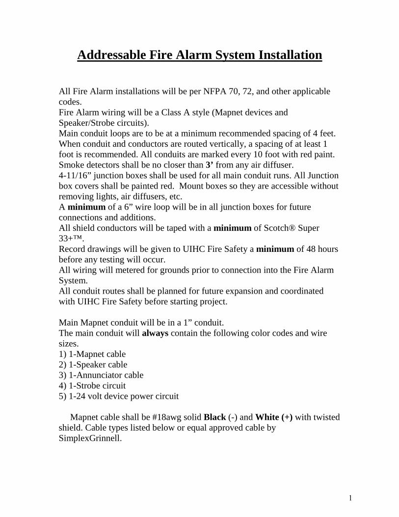
Addressable Fire Alarm System Installation
All Fire Alarm installations will be per NFPA 70, 72, and other applicable codes. Fire Alarm wiring will be a Class A style (Mapnet devices and Speaker/Strobe circuits). Main conduit loops are to be at a minimum recommended spacing of 4 feet. When conduit and conductors are routed vertically, a spacing of at least 1 foot is recommended. All conduits are marked every 10 foot with red paint. Smoke detectors shall be no closer than 3’ from any air diffuser. 4-11/16” junction boxes shall be used for all main conduit runs. All Junction box covers shall be painted red. Mount boxes so they are accessible without removing lights, air diffusers, etc. A minimum of a 6” wire loop will be in all junction boxes for future connections and additions. All shield conductors will be taped with a minimum of Scotch® Super 33+™. Record drawings will be given to UIHC Fire Safety a minimum of 48 hours before any testing will occur. All wiring will metered for grounds prior to connection into the Fire Alarm System. All conduit routes shall be planned for future expansion and coordinated with UIHC Fire Safety before starting project.
Main Mapnet conduit will be in a 1” conduit. The main conduit will always contain the following color codes and wire sizes. 1) 1-Mapnet cable2) 1-Speaker cable3) 1-Annunciator cable4) 1-Strobe circuit5) 1-24 volt device power circuit
Mapnet cable shall be #18awg solid Black (-) and White (+) with twisted shield. Cable types listed below or equal approved cable by SimplexGrinnell.
1
November 1, 2016
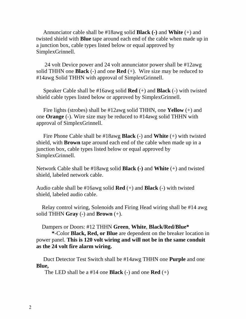
Annunciator cable shall be #18awg solid Black (-) and White (+) and twisted shield with Blue tape around each end of the cable when made up in a junction box, cable types listed below or equal approved by SimplexGrinnell.
24 volt Device power and 24 volt annunciator power shall be #12awg solid THHN one Black (-) and one Red (+). Wire size may be reduced to #14awg Solid THHN with approval of SimplexGrinnell.
Speaker Cable shall be #16awg solid Red (+) and Black (-) with twisted shield cable types listed below or approved by SimplexGrinnell.
Fire lights (strobes) shall be #12awg solid THHN, one Yellow (+) and one Orange (-). Wire size may be reduced to #14awg solid THHN with approval of SimplexGrinnell.
Fire Phone Cable shall be #18awg Black (-) and White (+) with twisted shield, with Brown tape around each end of the cable when made up in a junction box, cable types listed below or equal approved by SimplexGrinnell.
Network Cable shall be #18awg solid Black (-) and White (+) and twisted shield, labeled network cable.
Audio cable shall be #16awg solid Red (+) and Black (-) with twisted shield, labeled audio cable.
Relay control wiring, Solenoids and Firing Head wiring shall be #14 awg solid THHN Gray (-) and Brown (+).
Dampers or Doors: #12 THHN Green, White, Black/Red/Blue* *-Color Black, Red, or Blue are dependent on the breaker location in power panel. This is 120 volt wiring and will not be in the same conduit as the 24 volt fire alarm wiring.
Duct Detector Test Switch shall be #14awg THHN one Purple and one Blue, The LED shall be a #14 one Black (-) and one Red (+)
2
November 1, 2016

Wire Manufacturer Note: Windy City Wire, General Cable, The Cable Company, Tappan Wire and Cable, or other approved manufacturer by UIHC Fire Safety.
Any Changes of these wiring standards shall have written approval of both Safety/Security and SimplexGrinnell.
Note: Mapnet an IDnet are installed the same way.
2/16/2009
3
November 1, 2016

Appendix J
Intentionally Left Blank
November 1, 2016
Appendix K
Architect/Engineer Compliance Disposition Form
November 1, 2016
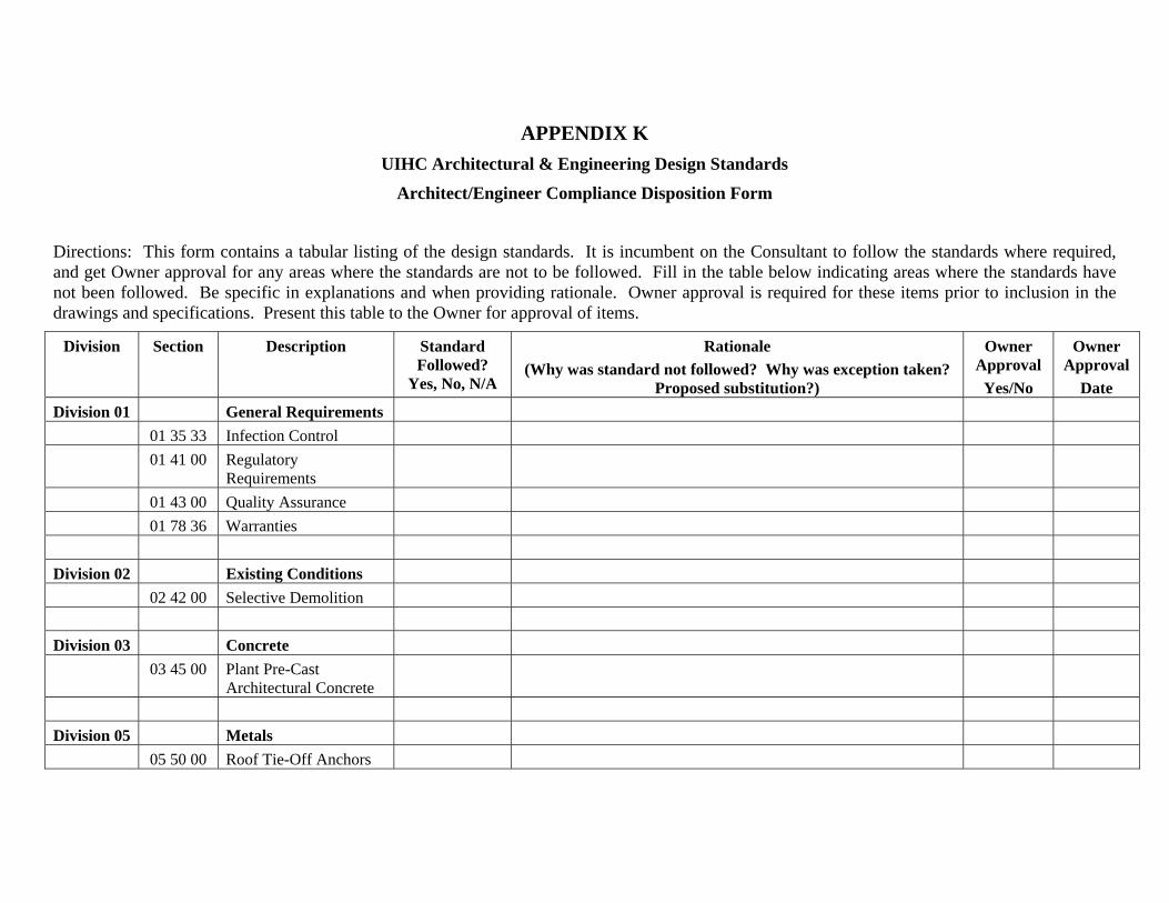
APPENDIX K UIHC Architectural & Engineering Design Standards
Architect/Engineer Compliance Disposition Form
Directions: This form contains a tabular listing of the design standards. It is incumbent on the Consultant to follow the standards where required, and get Owner approval for any areas where the standards are not to be followed. Fill in the table below indicating areas where the standards have not been followed. Be specific in explanations and when providing rationale. Owner approval is required for these items prior to inclusion in the drawings and specifications. Present this table to the Owner for approval of items.
Division Section Description Standard Followed?
Yes, No, N/A
Rationale (Why was standard not followed? Why was exception taken?
Proposed substitution?)
Owner Approval
Yes/No
Owner Approval
Date Division 01 General Requirements
01 35 33 Infection Control 01 41 00 Regulatory
Requirements 01 43 00 Quality Assurance 01 78 36 Warranties
Division 02 Existing Conditions 02 42 00 Selective Demolition
Division 03 Concrete 03 45 00 Plant Pre-Cast
Architectural Concrete
Division 05 Metals 05 50 00 Roof Tie-Off Anchors
November 1, 2016
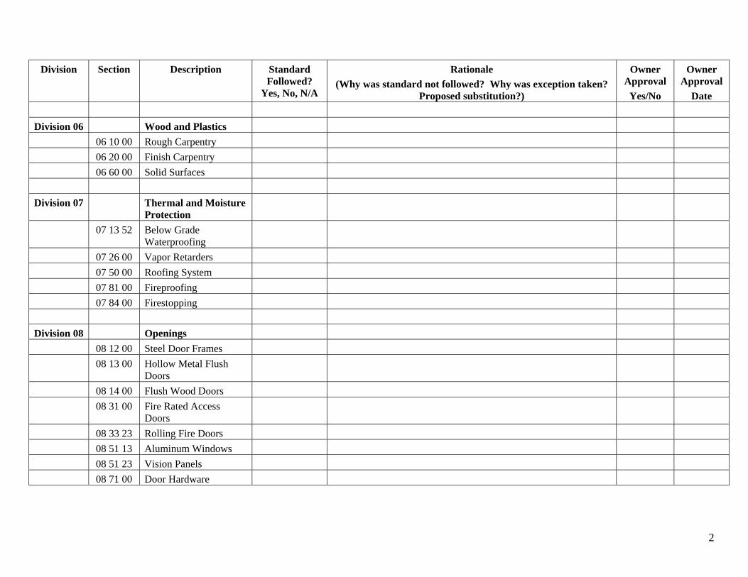
Division Section Description Standard Followed?
Yes, No, N/A
Rationale (Why was standard not followed? Why was exception taken?
Proposed substitution?)
Owner Approval
Yes/No
Owner Approval
Date
Division 06 Wood and Plastics 06 10 00 Rough Carpentry 06 20 00 Finish Carpentry 06 60 00 Solid Surfaces
Division 07 Thermal and Moisture Protection
07 13 52 Below Grade Waterproofing
07 26 00 Vapor Retarders 07 50 00 Roofing System 07 81 00 Fireproofing 07 84 00 Firestopping
Division 08 Openings 08 12 00 Steel Door Frames 08 13 00 Hollow Metal Flush
Doors 08 14 00 Flush Wood Doors 08 31 00 Fire Rated Access
Doors 08 33 23 Rolling Fire Doors 08 51 13 Aluminum Windows 08 51 23 Vision Panels 08 71 00 Door Hardware
2
November 1, 2016
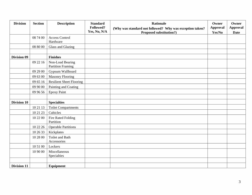
Division Section Description Standard Followed?
Yes, No, N/A
Rationale (Why was standard not followed? Why was exception taken?
Proposed substitution?)
Owner Approval
Yes/No
Owner Approval
Date 08 74 00 Access Control
Hardware 08 80 00 Glass and Glazing
Division 09 Finishes 09 22 16 Non-Load Bearing
Partition Framing 09 29 00 Gypsum Wallboard 09 63 00 Masonry Flooring 09 65 16 Resilient Sheet Flooring 09 90 00 Painting and Coating 09 96 56 Epoxy Paint
Division 10 Specialties 10 21 13 Toilet Compartments 10 21 23 Cubicles 10 22 00 Fire Rated Folding
Partition 10 22 26 Operable Partitions 10 26 33 Kickplates 10 28 00 Toilet and Bath
Accessories 10 51 00 Lockers 10 90 00 Miscellaneous
Specialties
Division 11 Equipment
3
November 1, 2016

Division Section Description Standard Followed?
Yes, No, N/A
Rationale (Why was standard not followed? Why was exception taken?
Proposed substitution?)
Owner Approval
Yes/No
Owner Approval
Date 11 28 13 Computers 11 47 00 Ice Machines 11 52 00 Audio-Visual
Equipment 11 52 13 Projection Screens 11 70 00 Healthcare Equipment
Division 12 Furnishings 12 30 00 Stainless Steel
Casework / Storage Cabinets
12 35 53 Metal Casework Including Fume Hoods
12 36 23 Solid Surface Countertops
Division 13 Special Construction 13 49 00 Radiation Protection
Division 14 Conveying Equipment 14 21 00 Elevators 14 92 00 Pneumatic Tube
Systems
Division 21 Fire Suppression 21 05 00 Common Work Results
for Fire Suppression
4
November 1, 2016
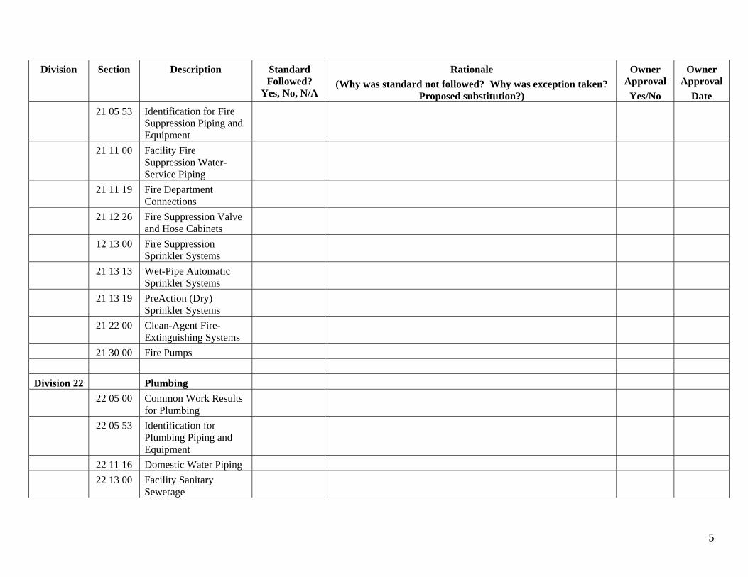
Division Section Description Standard Followed?
Yes, No, N/A
Rationale (Why was standard not followed? Why was exception taken?
Proposed substitution?)
Owner Approval
Yes/No
Owner Approval
Date 21 05 53 Identification for Fire
Suppression Piping and Equipment
21 11 00 Facility Fire Suppression Water-Service Piping
21 11 19 Fire Department Connections
21 12 26 Fire Suppression Valve and Hose Cabinets
12 13 00 Fire Suppression Sprinkler Systems
21 13 13 Wet-Pipe Automatic Sprinkler Systems
21 13 19 PreAction (Dry) Sprinkler Systems
21 22 00 Clean-Agent Fire-Extinguishing Systems
21 30 00 Fire Pumps
Division 22 Plumbing 22 05 00 Common Work Results
for Plumbing 22 05 53 Identification for
Plumbing Piping and Equipment
22 11 16 Domestic Water Piping 22 13 00 Facility Sanitary
Sewerage
5
November 1, 2016
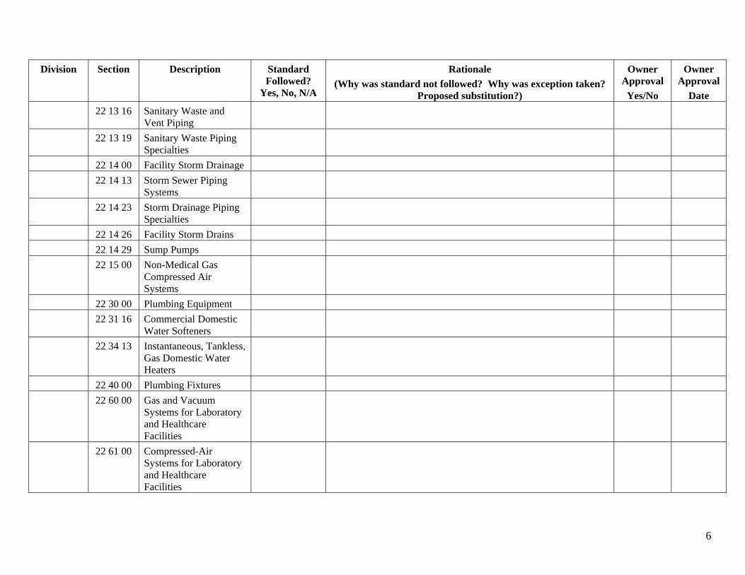
Division Section Description Standard Followed?
Yes, No, N/A
Rationale (Why was standard not followed? Why was exception taken?
Proposed substitution?)
Owner Approval
Yes/No
Owner Approval
Date 22 13 16 Sanitary Waste and
Vent Piping 22 13 19 Sanitary Waste Piping
Specialties 22 14 00 Facility Storm Drainage 22 14 13 Storm Sewer Piping
Systems 22 14 23 Storm Drainage Piping
Specialties 22 14 26 Facility Storm Drains 22 14 29 Sump Pumps 22 15 00 Non-Medical Gas
Compressed Air Systems
22 30 00 Plumbing Equipment 22 31 16 Commercial Domestic
Water Softeners 22 34 13 Instantaneous, Tankless,
Gas Domestic Water Heaters
22 40 00 Plumbing Fixtures 22 60 00 Gas and Vacuum
Systems for Laboratory and Healthcare Facilities
22 61 00 Compressed-Air Systems for Laboratory and Healthcare Facilities
6
November 1, 2016
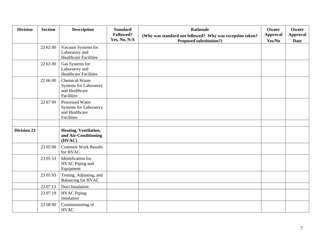
Division Section Description Standard Followed?
Yes, No, N/A
Rationale (Why was standard not followed? Why was exception taken?
Proposed substitution?)
Owner Approval
Yes/No
Owner Approval
Date 22 62 00 Vacuum Systems for
Laboratory and Healthcare Facilities
22 63 00 Gas Systems for Laboratory and Healthcare Facilities
22 66 00 Chemical-Waste Systems for Laboratory and Healthcare Facilities
22 67 00 Processed Water Systems for Laboratory and Healthcare Facilities
Division 23 Heating, Ventilation, and Air-Conditioning (HVAC)
23 05 00 Common Work Results for HVAC
23 05 53 Identification for HVAC Piping and Equipment
23 05 93 Testing, Adjusting, and Balancing for HVAC
23 07 13 Duct Insulation 23 07 19 HVAC Piping
Insulation 23 08 00 Commissioning of
HVAC
7
November 1, 2016
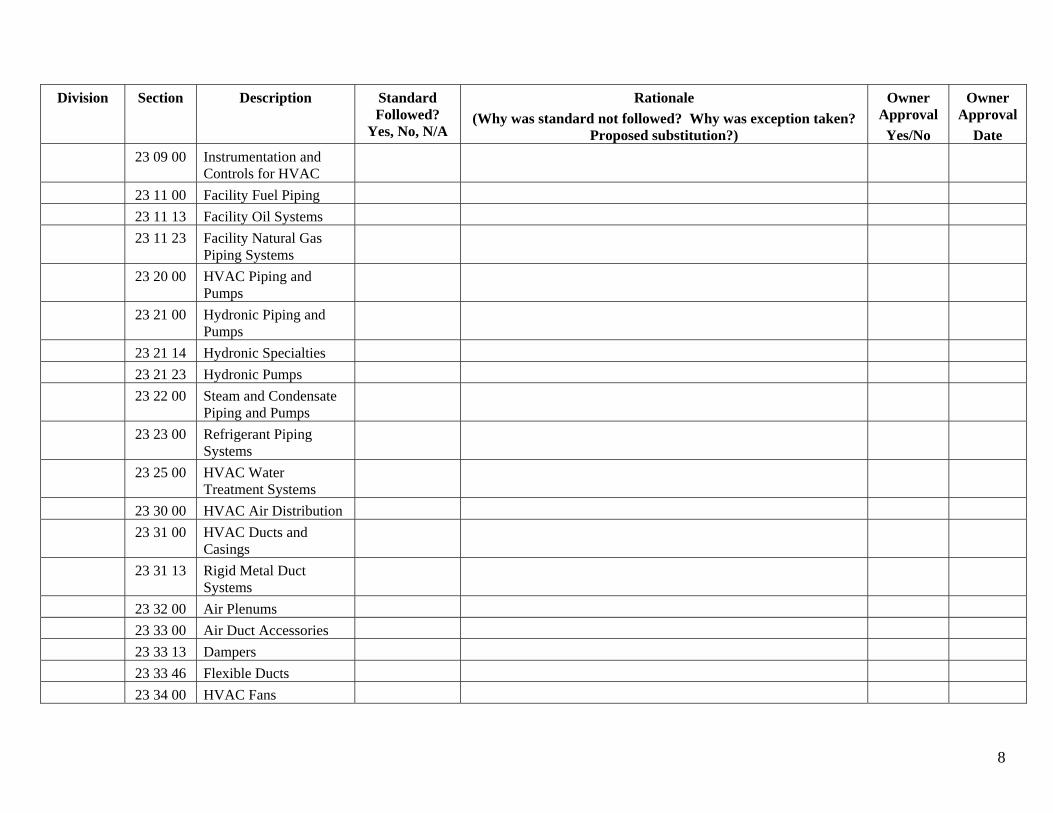
Division Section Description Standard Followed?
Yes, No, N/A
Rationale (Why was standard not followed? Why was exception taken?
Proposed substitution?)
Owner Approval
Yes/No
Owner Approval
Date 23 09 00 Instrumentation and
Controls for HVAC 23 11 00 Facility Fuel Piping 23 11 13 Facility Oil Systems 23 11 23 Facility Natural Gas
Piping Systems 23 20 00 HVAC Piping and
Pumps 23 21 00 Hydronic Piping and
Pumps 23 21 14 Hydronic Specialties 23 21 23 Hydronic Pumps 23 22 00 Steam and Condensate
Piping and Pumps 23 23 00 Refrigerant Piping
Systems 23 25 00 HVAC Water
Treatment Systems 23 30 00 HVAC Air Distribution 23 31 00 HVAC Ducts and
Casings 23 31 13 Rigid Metal Duct
Systems 23 32 00 Air Plenums 23 33 00 Air Duct Accessories 23 33 13 Dampers 23 33 46 Flexible Ducts 23 34 00 HVAC Fans
8
November 1, 2016
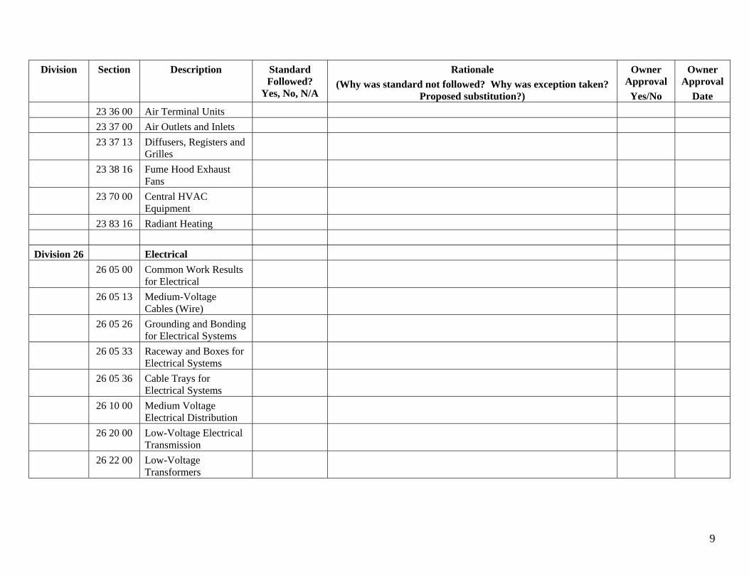
Division Section Description Standard Followed?
Yes, No, N/A
Rationale (Why was standard not followed? Why was exception taken?
Proposed substitution?)
Owner Approval
Yes/No
Owner Approval
Date 23 36 00 Air Terminal Units 23 37 00 Air Outlets and Inlets 23 37 13 Diffusers, Registers and
Grilles 23 38 16 Fume Hood Exhaust
Fans 23 70 00 Central HVAC
Equipment 23 83 16 Radiant Heating
Division 26 Electrical 26 05 00 Common Work Results
for Electrical 26 05 13 Medium-Voltage
Cables (Wire) 26 05 26 Grounding and Bonding
for Electrical Systems 26 05 33 Raceway and Boxes for
Electrical Systems 26 05 36 Cable Trays for
Electrical Systems 26 10 00 Medium Voltage
Electrical Distribution 26 20 00 Low-Voltage Electrical
Transmission 26 22 00 Low-Voltage
Transformers
9
November 1, 2016
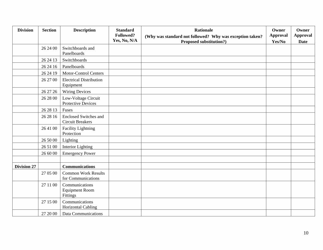
Division Section Description Standard Followed?
Yes, No, N/A
Rationale (Why was standard not followed? Why was exception taken?
Proposed substitution?)
Owner Approval
Yes/No
Owner Approval
Date 26 24 00 Switchboards and
Panelboards 26 24 13 Switchboards 26 24 16 Panelboards 26 24 19 Motor-Control Centers 26 27 00 Electrical Distribution
Equipment 26 27 26 Wiring Devices 26 28 00 Low-Voltage Circuit
Protective Devices 26 28 13 Fuses 26 28 16 Enclosed Switches and
Circuit Breakers 26 41 00 Facility Lightning
Protection 26 50 00 Lighting 26 51 00 Interior Lighting 26 60 00 Emergency Power
Division 27 Communications 27 05 00 Common Work Results
for Communications 27 11 00 Communications
Equipment Room Fittings
27 15 00 Communications Horizontal Cabling
27 20 00 Data Communications
10
November 1, 2016
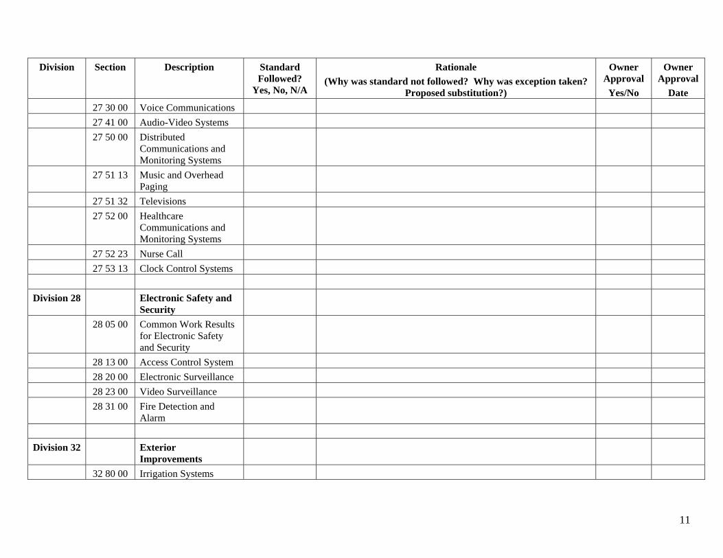
Division Section Description Standard Followed?
Yes, No, N/A
Rationale (Why was standard not followed? Why was exception taken?
Proposed substitution?)
Owner Approval
Yes/No
Owner Approval
Date 27 30 00 Voice Communications 27 41 00 Audio-Video Systems 27 50 00 Distributed
Communications and Monitoring Systems
27 51 13 Music and Overhead Paging
27 51 32 Televisions 27 52 00 Healthcare
Communications and Monitoring Systems
27 52 23 Nurse Call 27 53 13 Clock Control Systems
Division 28 Electronic Safety and Security
28 05 00 Common Work Results for Electronic Safety and Security
28 13 00 Access Control System 28 20 00 Electronic Surveillance 28 23 00 Video Surveillance 28 31 00 Fire Detection and
Alarm
Division 32 Exterior Improvements
32 80 00 Irrigation Systems
11
November 1, 2016
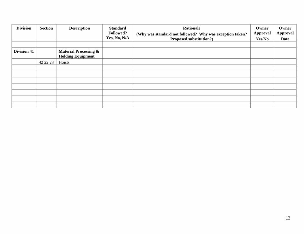
Division Section Description Standard Followed?
Yes, No, N/A
Rationale (Why was standard not followed? Why was exception taken?
Proposed substitution?)
Owner Approval
Yes/No
Owner Approval
Date
Division 41 Material Processing & Holding Equipment
42 22 23 Hoists
12
November 1, 2016

Appendix L
Typical Door Hardware and Rough-In Drawings by Security Level
November 1, 2016
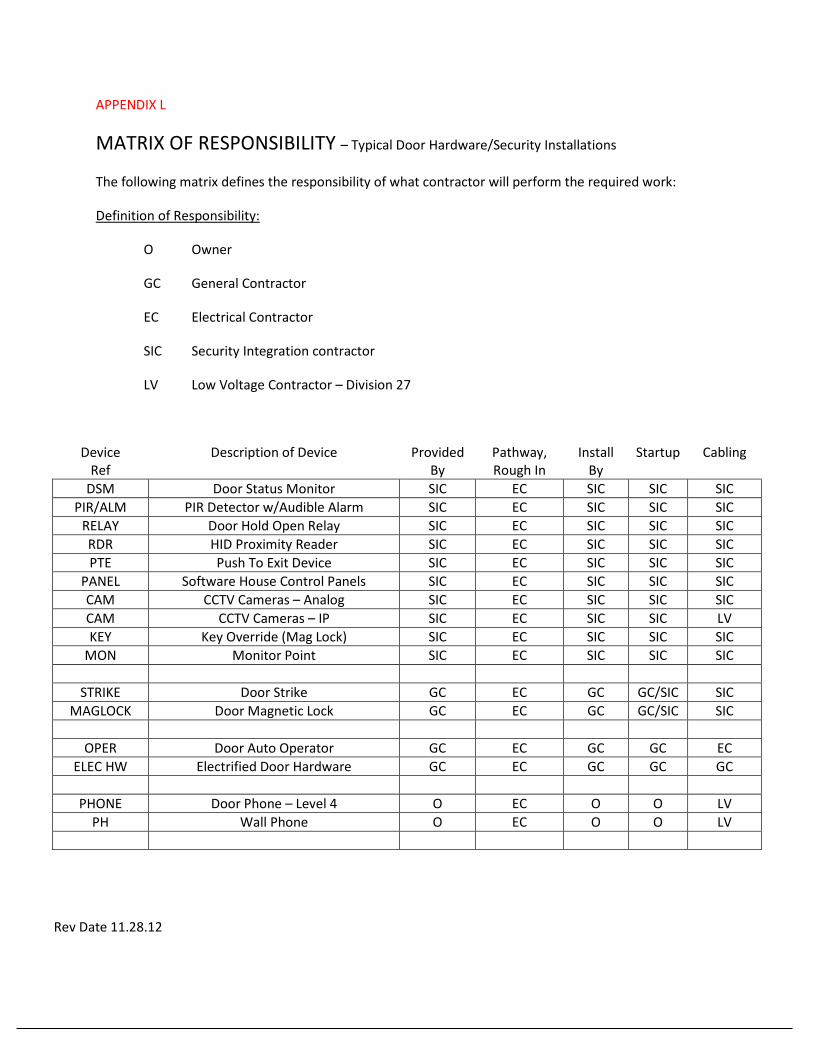
APPENDIX L
MATRIX OF RESPONSIBILITY – Typical Door Hardware/Security Installations
The following matrix defines the responsibility of what contractor will perform the required work:
Definition of Responsibility:
O Owner
GC General Contractor
EC Electrical Contractor
SIC Security Integration contractor
LV Low Voltage Contractor – Division 27
Device Ref
Description of Device Provided By
Pathway, Rough In
Install By
Startup Cabling
DSM Door Status Monitor SIC EC SIC SIC SIC PIR/ALM PIR Detector w/Audible Alarm SIC EC SIC SIC SIC
RELAY Door Hold Open Relay SIC EC SIC SIC SIC RDR HID Proximity Reader SIC EC SIC SIC SIC PTE Push To Exit Device SIC EC SIC SIC SIC
PANEL Software House Control Panels SIC EC SIC SIC SIC CAM CCTV Cameras – Analog SIC EC SIC SIC SIC CAM CCTV Cameras – IP SIC EC SIC SIC LV KEY Key Override (Mag Lock) SIC EC SIC SIC SIC
MON Monitor Point SIC EC SIC SIC SIC
STRIKE Door Strike GC EC GC GC/SIC SIC MAGLOCK Door Magnetic Lock GC EC GC GC/SIC SIC
OPER Door Auto Operator GC EC GC GC EC ELEC HW Electrified Door Hardware GC EC GC GC GC
PHONE Door Phone – Level 4 O EC O O LV PH Wall Phone O EC O O LV
Rev Date 11.28.12
November 1, 2016
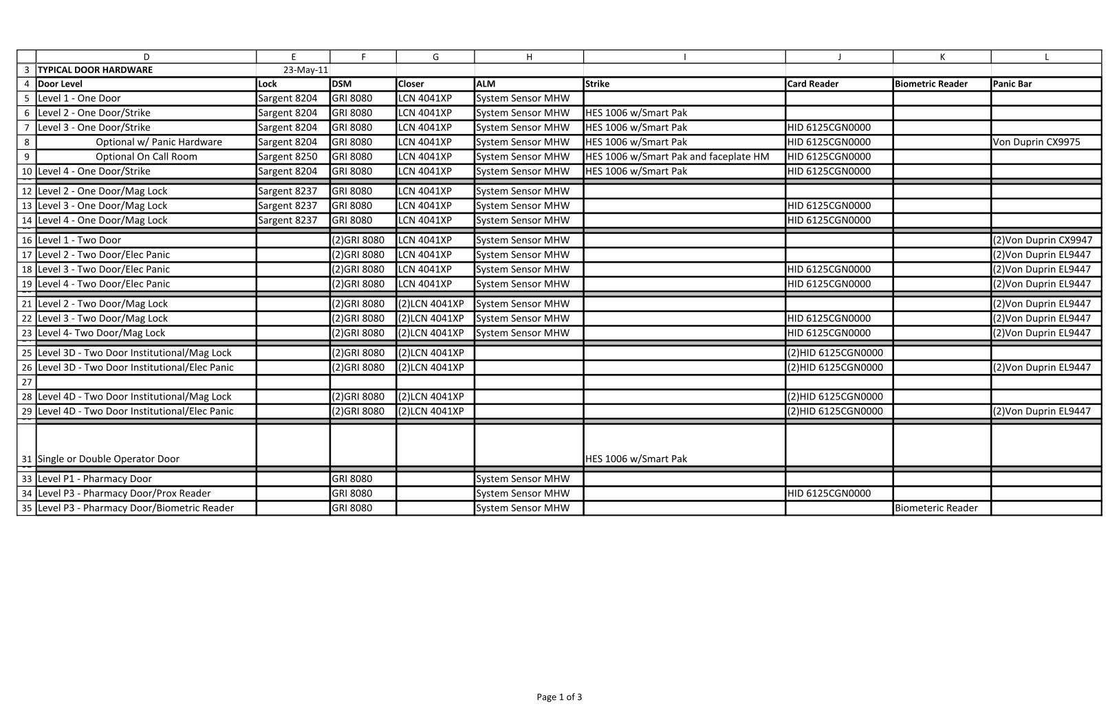
3456789101112131415161718192021222324252627282930
3132333435
D E F G H I J K LTYPICAL DOOR HARDWARE 23‐May‐11Door Level Lock DSM Closer ALM Strike Card Reader Biometric Reader Panic BarLevel 1 ‐ One Door Sargent 8204 GRI 8080 LCN 4041XP System Sensor MHWLevel 2 ‐ One Door/Strike Sargent 8204 GRI 8080 LCN 4041XP System Sensor MHW HES 1006 w/Smart PakLevel 3 ‐ One Door/Strike Sargent 8204 GRI 8080 LCN 4041XP System Sensor MHW HES 1006 w/Smart Pak HID 6125CGN0000
Optional w/ Panic Hardware Sargent 8204 GRI 8080 LCN 4041XP System Sensor MHW HES 1006 w/Smart Pak HID 6125CGN0000 Von Duprin CX9975Optional On Call Room Sargent 8250 GRI 8080 LCN 4041XP System Sensor MHW HES 1006 w/Smart Pak and faceplate HM HID 6125CGN0000
Level 4 ‐ One Door/Strike Sargent 8204 GRI 8080 LCN 4041XP System Sensor MHW HES 1006 w/Smart Pak HID 6125CGN0000
Level 2 ‐ One Door/Mag Lock Sargent 8237 GRI 8080 LCN 4041XP System Sensor MHWLevel 3 ‐ One Door/Mag Lock Sargent 8237 GRI 8080 LCN 4041XP System Sensor MHW HID 6125CGN0000Level 4 ‐ One Door/Mag Lock Sargent 8237 GRI 8080 LCN 4041XP System Sensor MHW HID 6125CGN0000
Level 1 ‐ Two Door (2)GRI 8080 LCN 4041XP System Sensor MHW (2)Von Duprin CX9947Level 2 ‐ Two Door/Elec Panic (2)GRI 8080 LCN 4041XP System Sensor MHW (2)Von Duprin EL9447Level 3 ‐ Two Door/Elec Panic (2)GRI 8080 LCN 4041XP System Sensor MHW HID 6125CGN0000 (2)Von Duprin EL9447Level 4 ‐ Two Door/Elec Panic (2)GRI 8080 LCN 4041XP System Sensor MHW HID 6125CGN0000 (2)Von Duprin EL9447
Level 2 ‐ Two Door/Mag Lock (2)GRI 8080 (2)LCN 4041XP System Sensor MHW (2)Von Duprin EL9447Level 3 ‐ Two Door/Mag Lock (2)GRI 8080 (2)LCN 4041XP System Sensor MHW HID 6125CGN0000 (2)Von Duprin EL9447Level 4‐ Two Door/Mag Lock (2)GRI 8080 (2)LCN 4041XP System Sensor MHW HID 6125CGN0000 (2)Von Duprin EL9447
Level 3D ‐ Two Door Institutional/Mag Lock (2)GRI 8080 (2)LCN 4041XP (2)HID 6125CGN0000Level 3D ‐ Two Door Institutional/Elec Panic (2)GRI 8080 (2)LCN 4041XP (2)HID 6125CGN0000 (2)Von Duprin EL9447
Level 4D ‐ Two Door Institutional/Mag Lock (2)GRI 8080 (2)LCN 4041XP (2)HID 6125CGN0000Level 4D ‐ Two Door Institutional/Elec Panic (2)GRI 8080 (2)LCN 4041XP (2)HID 6125CGN0000 (2)Von Duprin EL9447
Single or Double Operator Door HES 1006 w/Smart Pak
Level P1 ‐ Pharmacy Door GRI 8080 System Sensor MHWLevel P3 ‐ Pharmacy Door/Prox Reader GRI 8080 System Sensor MHW HID 6125CGN0000Level P3 ‐ Pharmacy Door/Biometric Reader GRI 8080 System Sensor MHW Biometeric Reader
Page 1 of 3
November 1, 2016
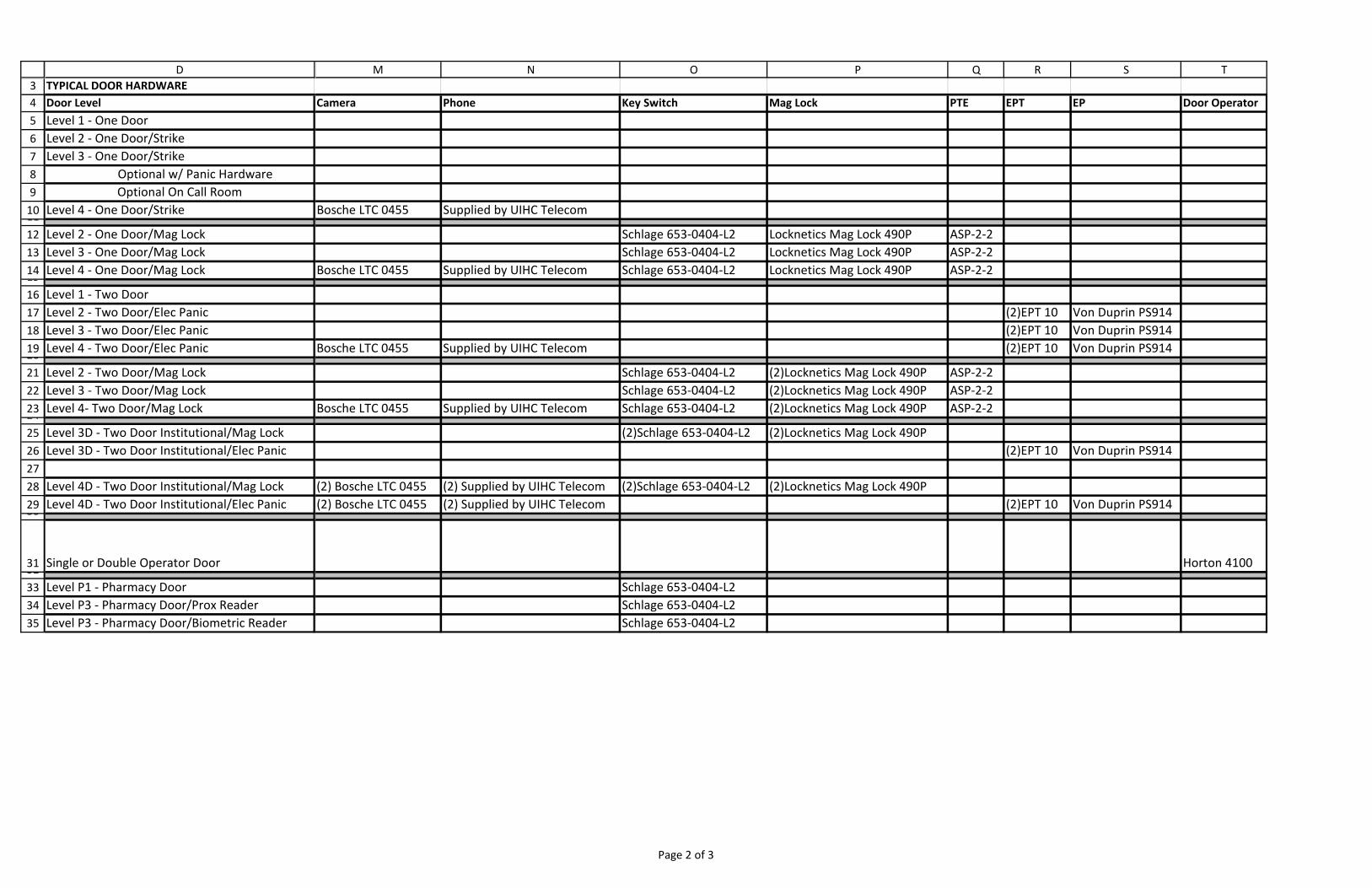
3456789101112131415161718192021222324252627282930
3132333435
DTYPICAL DOOR HARDWAREDoor LevelLevel 1 ‐ One DoorLevel 2 ‐ One Door/StrikeLevel 3 ‐ One Door/Strike
Optional w/ Panic HardwareOptional On Call Room
Level 4 ‐ One Door/Strike
Level 2 ‐ One Door/Mag LockLevel 3 ‐ One Door/Mag LockLevel 4 ‐ One Door/Mag Lock
Level 1 ‐ Two DoorLevel 2 ‐ Two Door/Elec PanicLevel 3 ‐ Two Door/Elec PanicLevel 4 ‐ Two Door/Elec Panic
Level 2 ‐ Two Door/Mag LockLevel 3 ‐ Two Door/Mag LockLevel 4‐ Two Door/Mag Lock
Level 3D ‐ Two Door Institutional/Mag LockLevel 3D ‐ Two Door Institutional/Elec Panic
Level 4D ‐ Two Door Institutional/Mag LockLevel 4D ‐ Two Door Institutional/Elec Panic
Single or Double Operator Door
Level P1 ‐ Pharmacy DoorLevel P3 ‐ Pharmacy Door/Prox ReaderLevel P3 ‐ Pharmacy Door/Biometric Reader
M N O P Q R S T
Camera Phone Key Switch Mag Lock PTE EPT EP Door Operator
Bosche LTC 0455 Supplied by UIHC Telecom
Schlage 653‐0404‐L2 Locknetics Mag Lock 490P ASP‐2‐2Schlage 653‐0404‐L2 Locknetics Mag Lock 490P ASP‐2‐2
Bosche LTC 0455 Supplied by UIHC Telecom Schlage 653‐0404‐L2 Locknetics Mag Lock 490P ASP‐2‐2
(2)EPT 10 Von Duprin PS914(2)EPT 10 Von Duprin PS914
Bosche LTC 0455 Supplied by UIHC Telecom (2)EPT 10 Von Duprin PS914
Schlage 653‐0404‐L2 (2)Locknetics Mag Lock 490P ASP‐2‐2Schlage 653‐0404‐L2 (2)Locknetics Mag Lock 490P ASP‐2‐2
Bosche LTC 0455 Supplied by UIHC Telecom Schlage 653‐0404‐L2 (2)Locknetics Mag Lock 490P ASP‐2‐2
(2)Schlage 653‐0404‐L2 (2)Locknetics Mag Lock 490P(2)EPT 10 Von Duprin PS914
(2) Bosche LTC 0455 (2) Supplied by UIHC Telecom (2)Schlage 653‐0404‐L2 (2)Locknetics Mag Lock 490P(2) Bosche LTC 0455 (2) Supplied by UIHC Telecom (2)EPT 10 Von Duprin PS914
Horton 4100
Schlage 653‐0404‐L2Schlage 653‐0404‐L2Schlage 653‐0404‐L2
Page 2 of 3
November 1, 2016
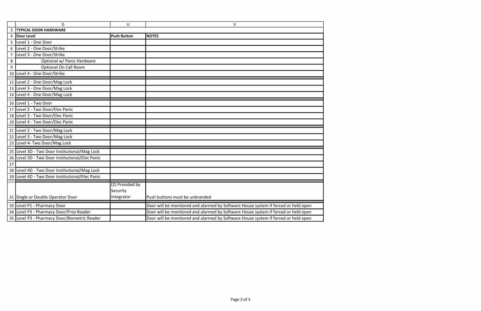
3456789101112131415161718192021222324252627282930
3132333435
DTYPICAL DOOR HARDWAREDoor LevelLevel 1 ‐ One DoorLevel 2 ‐ One Door/StrikeLevel 3 ‐ One Door/Strike
Optional w/ Panic HardwareOptional On Call Room
Level 4 ‐ One Door/Strike
Level 2 ‐ One Door/Mag LockLevel 3 ‐ One Door/Mag LockLevel 4 ‐ One Door/Mag Lock
Level 1 ‐ Two DoorLevel 2 ‐ Two Door/Elec PanicLevel 3 ‐ Two Door/Elec PanicLevel 4 ‐ Two Door/Elec Panic
Level 2 ‐ Two Door/Mag LockLevel 3 ‐ Two Door/Mag LockLevel 4‐ Two Door/Mag Lock
Level 3D ‐ Two Door Institutional/Mag LockLevel 3D ‐ Two Door Institutional/Elec Panic
Level 4D ‐ Two Door Institutional/Mag LockLevel 4D ‐ Two Door Institutional/Elec Panic
Single or Double Operator Door
Level P1 ‐ Pharmacy DoorLevel P3 ‐ Pharmacy Door/Prox ReaderLevel P3 ‐ Pharmacy Door/Biometric Reader
U V
Push Button NOTES
(2) Provided by Security Integrator Push buttons must be unbranded
Door will be monitored and alarmed by Software House system if forced or held openDoor will be monitored and alarmed by Software House system if forced or held openDoor will be monitored and alarmed by Software House system if forced or held open
Page 3 of 3
November 1, 2016
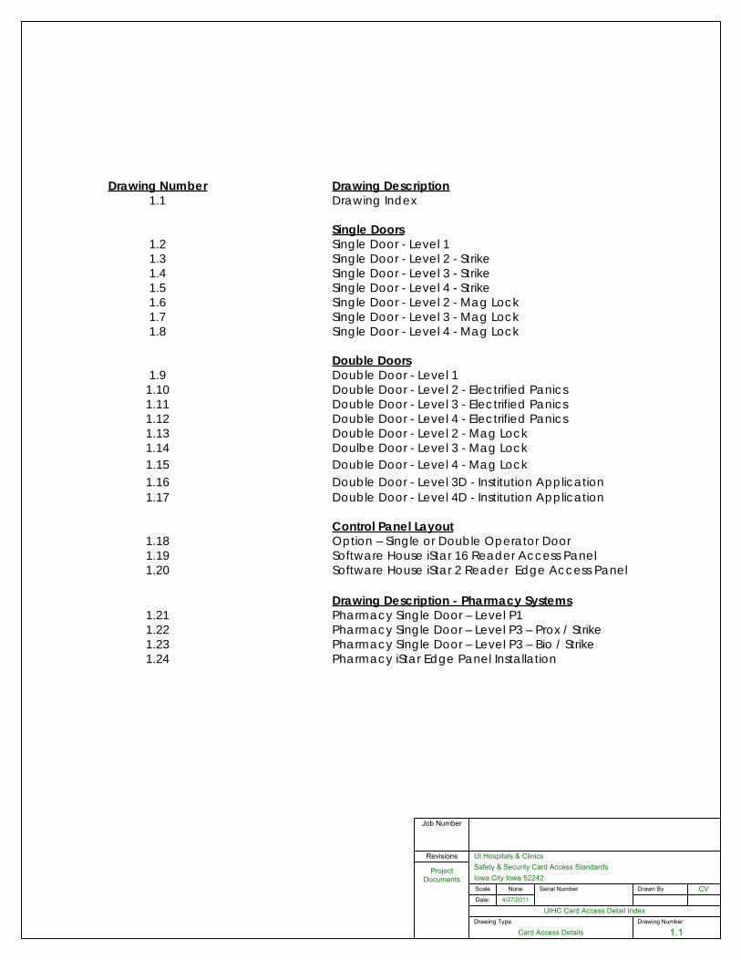
Drawing Number
1.1
UIHC Card Access Detail IndexDate:
UI Hospitals & Clinics
Iowa City Iowa 52242Scale
4/27/2011
CV
Job Number
Serial Number Drawn By
Project Documents
Revisions
Drawing Type
Card Access Details
None
Safety & Security Card Access Standards
Drawing Number Drawing Description1.1 Drawing Index
Single Doors1.2 Single Door - Level 11.3 Single Door - Level 2 - Strike1.4 Single Door - Level 3 - Strike 1.5 Single Door - Level 4 - Strike1.6 Single Door - Level 2 - Mag Lock1.7 Single Door - Level 3 - Mag Lock1.8 Single Door - Level 4 - Mag Lock
Double Doors1.9 Double Door - Level 11.10 Double Door - Level 2 - Electrified Panics1.11 Double Door - Level 3 - Electrified Panics1.12 Double Door - Level 4 - Electrified Panics1.13 Double Door - Level 2 - Mag Lock1.14 Doulbe Door - Level 3 - Mag Lock1.15 Double Door - Level 4 - Mag Lock1.16 Double Door - Level 3D - Institution Application1.17 Double Door - Level 4D - Institution Application
Control Panel Layout1.18 Option – Single or Double Operator Door1.19 Software House iStar 16 Reader Access Panel1.20 Software House iStar 2 Reader Edge Access Panel
Drawing Description - Pharmacy Systems1.21 Pharmacy Single Door – Level P11.22 Pharmacy Single Door – Level P3 – Prox / Strike1.23 Pharmacy Single Door – Level P3 – Bio / Strike1.24 Pharmacy iStar Edge Panel Installation
November 1, 2016
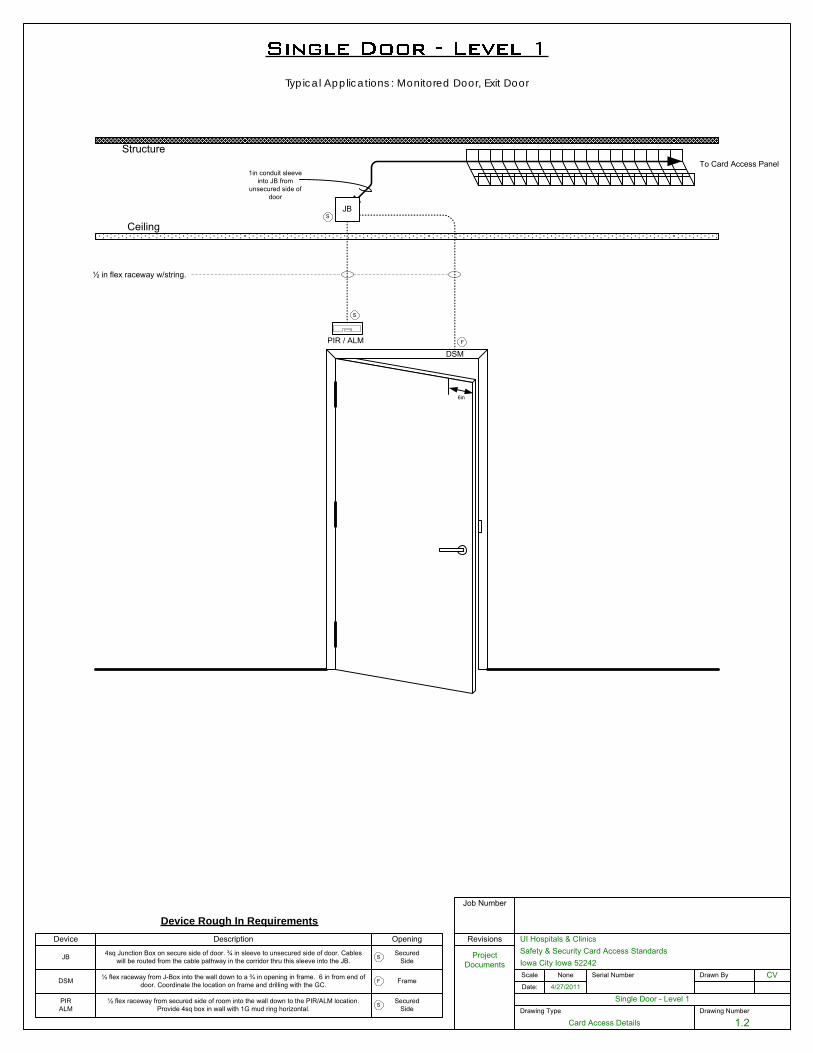
Drawing Number
1.2
Single Door - Level 1Date:
UI Hospitals & Clinics
Iowa City Iowa 52242Scale
4/27/2011
CV
Job Number
Serial Number Drawn By
Project Documents
Revisions
Drawing Type
Card Access Details
None
Safety & Security Card Access Standards
Ceiling
StructureTo Card Access Panel
½ in flex raceway w/string.
6in
DSM
Device Rough In Requirements
JB
Device Description Opening
PIR / ALM F
S
1in conduit sleeve into JB from
unsecured side of door
S
JB 4sq Junction Box on secure side of door. ¾ in sleeve to unsecured side of door. Cables will be routed from the cable pathway in the corridor thru this sleeve into the JB.
SecuredSideS
DSM ½ flex raceway from J-Box into the wall down to a ¾ in opening in frame. 6 in from end of door. Coordinate the location on frame and drilling with the GC. FrameF
PIRALM
SecuredSideS
½ flex raceway from secured side of room into the wall down to the PIR/ALM location. Provide 4sq box in wall with 1G mud ring horizontal.
Typical Applications : Monitored Door, Exit Door
November 1, 2016
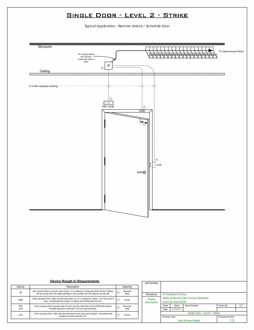
Drawing Number
1.3
Single Door - Level 2 - StrikeDate:
UI Hospitals & Clinics
Iowa City Iowa 52242Scale
4/27/2011
CV
Job Number
Serial Number Drawn By
Project Documents
Revisions
Drawing Type
Card Access Details
None
Safety & Security Card Access Standards
Ceiling
StructureTo Card Access Panel
½ in flex raceway w/string.
6in
LCK
DSM
Device Rough In Requirements
JB
Device Description Opening
F
PIR / ALM F
S
1in conduit sleeve into JB from
unsecured side of door
S
JB 4sq Junction Box on secure side of door. ¾ in sleeve to unsecured side of door. Cables will be routed from the cable pathway in the corridor thru this sleeve into the JB.
SecuredSideS
DSM ½ flex raceway from J-Box into the wall down to a ¾ in opening in frame. 6 in from end of door. Coordinate the location on frame and drilling with the GC. FrameF
LCK ½ flex raceway from J-Box into the wall down to the door lock location. Coordinate the location on frame with the GC. FrameF
PIRALM
SecuredSideS
½ flex raceway from secured side of room into the wall down to the PIR/ALM location. Provide 4sq box in wall with 1G mud ring horizontal.
Typical Application : Remote Unlock / Schedule Door
November 1, 2016
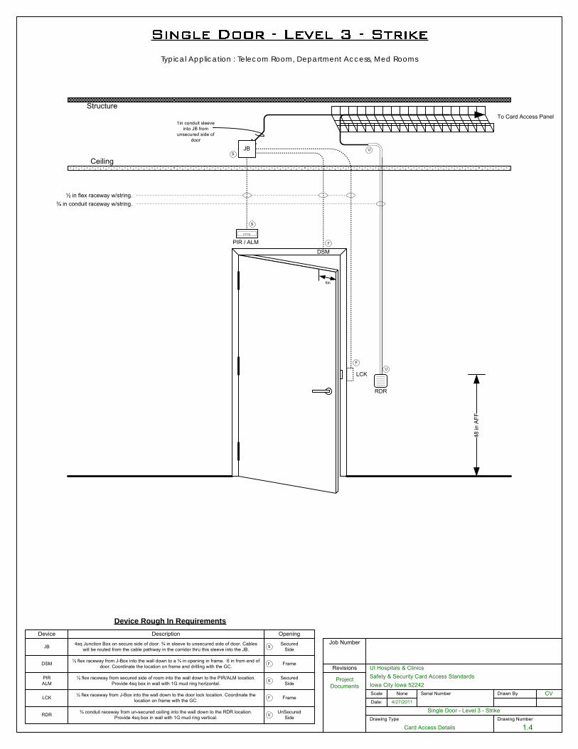
Drawing Number
1.4
Single Door - Level 3 - StrikeDate:
UI Hospitals & Clinics
Iowa City Iowa 52242Scale
4/27/2011
CV
Job Number
Serial Number Drawn By
Project Documents
Revisions
Drawing Type
Card Access Details
None
Safety & Security Card Access Standards
Ceiling
Structure
48 in
AFF
To Card Access Panel
½ in flex raceway w/string.¾ in conduit raceway w/string.
6in
RDR
LCK
DSM
Device Rough In Requirements
JB
Device Description Opening
F
U
PIR / ALM F
S
1in conduit sleeve into JB from
unsecured side of door
S
JB 4sq Junction Box on secure side of door. ¾ in sleeve to unsecured side of door. Cables will be routed from the cable pathway in the corridor thru this sleeve into the JB.
SecuredSideS
RDR ¾ conduit raceway from un-secured ceiling into the wall down to the RDR location. Provide 4sq box in wall with 1G mud ring vertical.
UnSecuredSideU
U
DSM ½ flex raceway from J-Box into the wall down to a ¾ in opening in frame. 6 in from end of door. Coordinate the location on frame and drilling with the GC. FrameF
LCK ½ flex raceway from J-Box into the wall down to the door lock location. Coordinate the location on frame with the GC. FrameF
PIRALM
SecuredSideS
½ flex raceway from secured side of room into the wall down to the PIR/ALM location. Provide 4sq box in wall with 1G mud ring horizontal.
Typical Application : Telecom Room, Department Access, Med Rooms
November 1, 2016
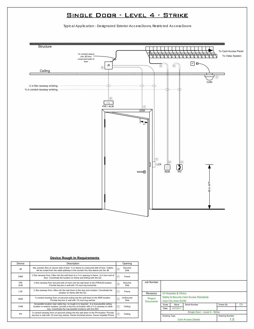
Drawing Number
1.5
Single Door - Level 4 - StrikeDate:
UI Hospitals & Clinics
Iowa City Iowa 52242Scale
4/27/2011
CV
Job Number
Serial Number Drawn By
Project Documents
Revisions
Drawing Type
Card Access Details
None
Safety & Security Card Access Standards
Ceiling
Structure
48 in
AFF
To Card Access Panel
½ in flex raceway w/string.¾ in conduit raceway w/string.
RDR
LCK
To Video System
Device Rough In Requirements
JB
Device Description Opening
F
U
PIR / ALM F
S
1in conduit sleeve into JB from
unsecured side of door
IP
C
CAM
S
JB 4sq Junction Box on secure side of door. ¾ in sleeve to unsecured side of door. Cables will be routed from the cable pathway in the corridor thru this sleeve into the JB.
SecuredSideS
RDR ¾ conduit raceway from un-secured ceiling into the wall down to the RDR location. Provide 4sq box in wall with 1G mud ring vertical.
UnSecuredSideU
CAMAccessible location near cable tray, no rough-in is required. In a inaccessible ceiling
location or exterior lcoation, provide a 4sq box at location with a ¾ in raceway to cable tray. Coordinate the inaccessible locations with the SSC
CeilingC
U
6in
DSM
DSM ½ flex raceway from J-Box into the wall down to a ¾ in opening in frame. 6 in from end of door. Coordinate the location on frame and drilling with the GC. FrameF
LCK ½ flex raceway from J-Box into the wall down to the door lock location. Coordinate the location on frame with the GC. FrameF
PIRALM
SecuredSideS
½ flex raceway from secured side of room into the wall down to the PIR/ALM location. Provide 4sq box in wall with 1G mud ring horizontal.
PH
U
U
PH ¾ conduit raceway from un-secured ceiling into the wall down to the PH location. Provide 4sq box in wall with 1G mud ring vertical. Owner furnished phone. Owner Installed Phone CeilingU
Typical Application : Designated Exterior Access Doors, Restricted Access Doors
November 1, 2016
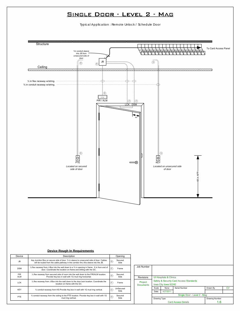
Drawing Number
1.6
Single Door - Level 2 - MagDate:
UI Hospitals & Clinics
Iowa City Iowa 52242Scale
4/27/2011
CV
Job Number
Serial Number Drawn By
Project Documents
Revisions
Drawing Type
Card Access Details
None
Safety & Security Card Access Standards
Ceiling
StructureTo Card Access Panel
½ in flex raceway w/string.
6in
LCK DSM
Device Rough In Requirements
JB
Device Description Opening
FPIR / ALM F
S
1in conduit sleeve into JB from
unsecured side of door
S
JB 4sq Junction Box on secure side of door. ¾ in sleeve to unsecured side of door. Cables will be routed from the cable pathway in the corridor thru this sleeve into the JB.
SecuredSideS
DSM ½ flex raceway from J-Box into the wall down to a ¾ in opening in frame. 6 in from end of door. Coordinate the location on frame and drilling with the GC. FrameF
LCK ½ flex raceway from J-Box into the wall down to the door lock location. Coordinate the location on frame with the GC. FrameF
PIRALM
SecuredSideS
½ flex raceway from secured side of room into the wall down to the PIR/ALM location. Provide 4sq box in wall with 1G mud ring horizontal.
Typical Application : Remote Unlock / Schedule Door
48 in
AFF
U
U
Located on unsecured side of door
KEY ¾ conduit raceway from KS.Provide 4sq box in wall with 1G mud ring vertical. UnSecuredSideU
¾ in conduit raceway w/string.
KEYPTELocated on secured
side of door
S
S
PTE SecuredSide
¾ conduit raceway from the ceiling to the PTE location. Provide 4sq box in wall with 1G mud ring vertical. S
November 1, 2016
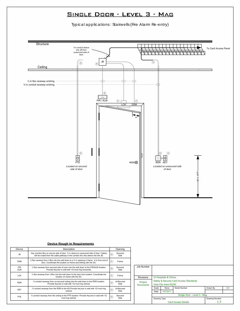
Drawing Number
1.7
Single Door - Level 3 - MagDate:
UI Hospitals & Clinics
Iowa City Iowa 52242Scale
4/27/2011
CV
Job Number
Serial Number Drawn By
Project Documents
Revisions
Drawing Type
Card Access Details
None
Safety & Security Card Access Standards
Ceiling
Structure
48 in
AFF
To Card Access Panel
½ in flex raceway w/string.¾ in conduit raceway w/string.
6in
RDR
LCK DSM
Device Rough In Requirements
JB
Device Description Opening
F
U
PIR / ALM F
S
1in conduit sleeve into JB from
unsecured side of door
S
JB 4sq Junction Box on secure side of door. ¾ in sleeve to unsecured side of door. Cables will be routed from the cable pathway in the corridor thru this sleeve into the JB.
SecuredSideS
RDR ¾ conduit raceway from un-secured ceiling into the wall down to the RDR location. Provide 4sq box in wall with 1G mud ring vertical.
UnSecuredSideU
U
DSM ½ flex raceway from J-Box into the wall down to a ¾ in opening in frame. 6 in from end of door. Coordinate the location on frame and drilling with the GC. FrameF
LCK ½ flex raceway from J-Box into the wall down to the door lock location. Coordinate the location on frame with the GC. FrameF
PIRALM
SecuredSideS
½ flex raceway from secured side of room into the wall down to the PIR/ALM location. Provide 4sq box in wall with 1G mud ring horizontal.
U
PTELocated on secured
side of door
S
S
Located on unsecured side of door
KEY ¾ conduit raceway from the RDR to the KS.Provide 4sq box in wall with 1G mud ring vertical.
UnSecuredSideU
PTE SecuredSide
¾ conduit raceway from the ceiling to the PTE location. Provide 4sq box in wall with 1G mud ring vertical. S
Typical applications : Stairwells (Fire Alarm Re-entry)
KEY
November 1, 2016
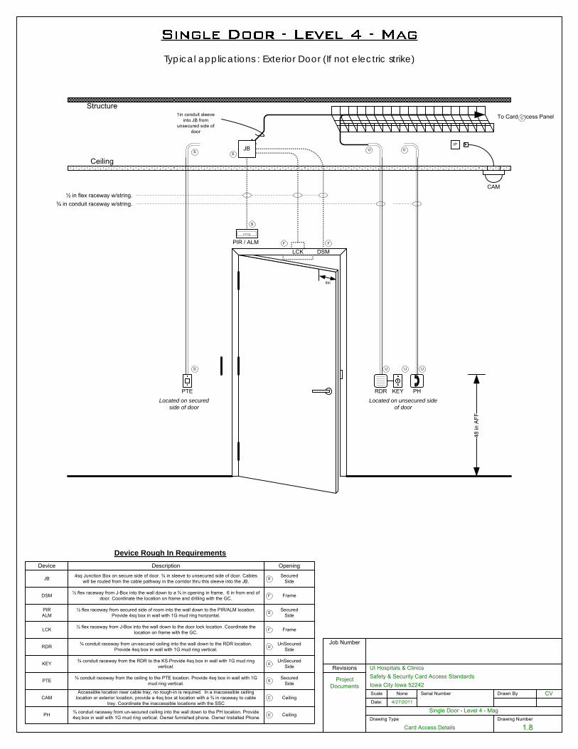
Drawing Number
1.8
Single Door - Level 4 - MagDate:
UI Hospitals & Clinics
Iowa City Iowa 52242Scale
4/27/2011
CV
Job Number
Serial Number Drawn By
Project Documents
Revisions
Drawing Type
Card Access Details
None
Safety & Security Card Access Standards
Ceiling
Structure
48 in
AFF
To Card Access Panel
½ in flex raceway w/string.¾ in conduit raceway w/string.
6in
RDR
LCK DSM
Device Rough In Requirements
JB
Device Description Opening
F
U
PIR / ALM F
S
1in conduit sleeve into JB from
unsecured side of door
S
JB 4sq Junction Box on secure side of door. ¾ in sleeve to unsecured side of door. Cables will be routed from the cable pathway in the corridor thru this sleeve into the JB.
SecuredSideS
RDR ¾ conduit raceway from un-secured ceiling into the wall down to the RDR location. Provide 4sq box in wall with 1G mud ring vertical.
UnSecuredSideU
U
DSM ½ flex raceway from J-Box into the wall down to a ¾ in opening in frame. 6 in from end of door. Coordinate the location on frame and drilling with the GC. FrameF
LCK ½ flex raceway from J-Box into the wall down to the door lock location. Coordinate the location on frame with the GC. FrameF
PIRALM
SecuredSideS
½ flex raceway from secured side of room into the wall down to the PIR/ALM location. Provide 4sq box in wall with 1G mud ring horizontal.
U
PTELocated on secured
side of door
S
S
Located on unsecured side of door
KEY ¾ conduit raceway from the RDR to the KS.Provide 4sq box in wall with 1G mud ring vertical.
UnSecuredSideU
PTE SecuredSide
¾ conduit raceway from the ceiling to the PTE location. Provide 4sq box in wall with 1G mud ring vertical. S
Typical applications : Exterior Door (If not electric strike)
KEY
IP
C
CAM
CAMAccessible location near cable tray, no rough-in is required. In a inaccessible ceiling
location or exterior lcoation, provide a 4sq box at location with a ¾ in raceway to cable tray. Coordinate the inaccessible locations with the SSC
CeilingC
PH
U
U
PH ¾ conduit raceway from un-secured ceiling into the wall down to the PH location. Provide 4sq box in wall with 1G mud ring vertical. Owner furnished phone. Owner Installed Phone CeilingU
November 1, 2016
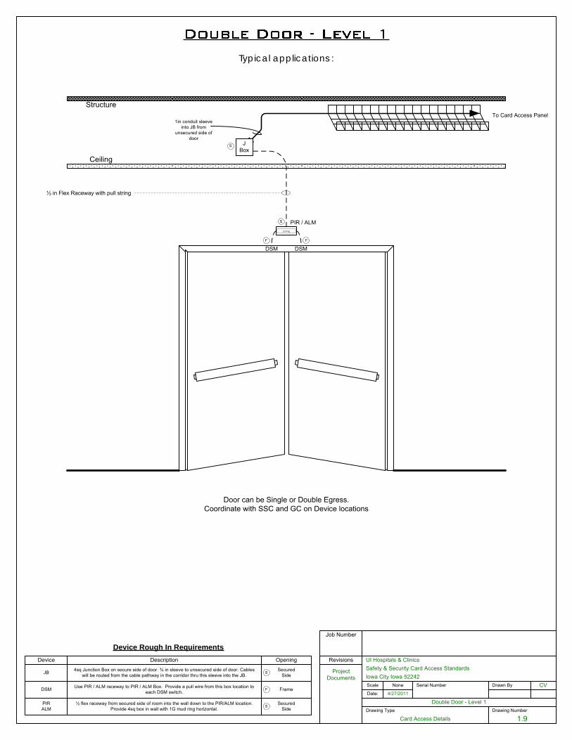
Drawing Number
1.9
Double Door - Level 1Date:
UI Hospitals & Clinics
Iowa City Iowa 52242Scale
4/27/2011
CV
Job Number
Serial Number Drawn By
Project Documents
Revisions
Drawing Type
Card Access Details
None
Safety & Security Card Access Standards
1in conduit sleeve into JB from
unsecured side of door
Device Rough In RequirementsDevice Description Opening
JB 4sq Junction Box on secure side of door. ¾ in sleeve to unsecured side of door. Cables will be routed from the cable pathway in the corridor thru this sleeve into the JB.
SecuredSideS
Ceiling
Structure
JBox
To Card Access Panel
½ in Flex Raceway with pull string
PIR / ALM
DSMDSMFF
S
S
DSM
Door can be Single or Double Egress.Coordinate with SSC and GC on Device locations
PIRALM
SecuredSideS
½ flex raceway from secured side of room into the wall down to the PIR/ALM location. Provide 4sq box in wall with 1G mud ring horizontal.
DSM Use PIR / ALM raceway to PIR / ALM Box. Provide a pull wire from this box location to each DSM switch. FrameF
Typical applications :
November 1, 2016
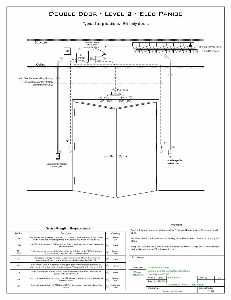
Drawing Number
1.10
Double Door - Level 2 - Elec PanicsDate:
UI Hospitals & Clinics
Iowa City Iowa 52242Scale
4/27/2011
CV
Job Number
Serial Number Drawn By
Project Documents
Revisions
Drawing Type
Card Access Details
None
Safety & Security Card Access Standards
1in conduit sleeve into JB from
unsecured side of door
Ceiling
Structure
JBox
To Card Access Panel
½ in Flex Raceway with pull string
PIR / ALM
To Video System
DSM
EPEP
Located on public side of door
Device Rough In RequirementsDevice Description Opening
JB 4sq Junction Box on secure side of door. ¾ in sleeve to unsecured side of door. Cables will be routed from the cable pathway in the corridor thru this sleeve into the JB.
SecuredSideS
F
F
F
S
S
DSMF
EPPowerSupply
½ in Flex Raceway for EP Only (Informational Only)
S
DSM Use PIR / ALM raceway to PIR / ALM Box. Provide a pull wire from this box location to each DSM switch. FrameF
PIRALM
SecuredSideS
½ flex raceway from secured side of room into the wall down to the PIR/ALM location. Provide 4sq box in wall with 1G mud ring horizontal.
LCK
Typical applications : Exit only doors
LCK LCK
FF
EP ½ flex raceway from power supply to each transfer hinge. This work is shown for coordination of rough ins only. Wiring related to Electrified Panics by EC FrameF
LCK ½ flex raceway from PIR into the wall down to the door lock location. Coordinate the location on frame with the GC. FrameF
DH Door Holder Circuit is tied to the power supply. EP’s normally retracted unless a fire alarm is active and door holder circuit is released. Wiring related to DH and EP by EC. CeilingF
DH
PTELocated on secured
side of door
S
S
PTE SecuredSide
¾ conduit raceway from the ceiling to the PTE location. Provide 4sq box in wall with 1G mud ring vertical. S
Sequence
Door will be monitored and alarmed by Software House system if forced or held open.
Electrified Panics will be retracted during normal operation. Extended during fire alarm.
Mag Locks will secure the door under normal operation. Mag Locks de-energized during fire alarm and EP will extend to latch.
KEY ¾ conduit raceway from the RDR to the KS.Provide 4sq box in wall with 1G mud ring vertical.
UnSecuredSideU
KSLocated on public
side of door
U
U
November 1, 2016
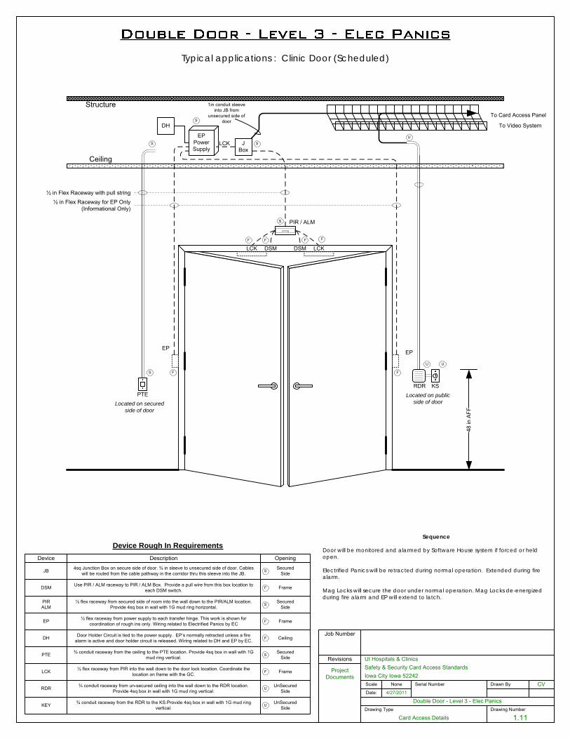
Drawing Number
1.11
Double Door - Level 3 - Elec PanicsDate:
UI Hospitals & Clinics
Iowa City Iowa 52242Scale
4/27/2011
CV
Job Number
Serial Number Drawn By
Project Documents
Revisions
Drawing Type
Card Access Details
None
Safety & Security Card Access Standards
RDR ¾ conduit raceway from un-secured ceiling into the wall down to the RDR location. Provide 4sq box in wall with 1G mud ring vertical.
UnSecuredSideU
1in conduit sleeve into JB from
unsecured side of door
Ceiling
Structure
JBox
To Card Access Panel
½ in Flex Raceway with pull string
PIR / ALM
To Video System
DSM
EPEP
Located on public side of door
Device Rough In RequirementsDevice Description Opening
JB 4sq Junction Box on secure side of door. ¾ in sleeve to unsecured side of door. Cables will be routed from the cable pathway in the corridor thru this sleeve into the JB.
SecuredSideS
F
F
F
S
S
DSMF
EPPowerSupply
½ in Flex Raceway for EP Only (Informational Only)
S
DSM Use PIR / ALM raceway to PIR / ALM Box. Provide a pull wire from this box location to each DSM switch. FrameF
PIRALM
SecuredSideS
½ flex raceway from secured side of room into the wall down to the PIR/ALM location. Provide 4sq box in wall with 1G mud ring horizontal.
LCK
48 in
AFF
U
U
Typical applications : Clinic Door (Scheduled)
LCK LCK
FF
EP ½ flex raceway from power supply to each transfer hinge. This work is shown for coordination of rough ins only. Wiring related to Electrified Panics by EC FrameF
LCK ½ flex raceway from PIR into the wall down to the door lock location. Coordinate the location on frame with the GC. FrameF
DH Door Holder Circuit is tied to the power supply. EP’s normally retracted unless a fire alarm is active and door holder circuit is released. Wiring related to DH and EP by EC. CeilingF
DH
PTELocated on secured
side of door
S
S
PTE SecuredSide
¾ conduit raceway from the ceiling to the PTE location. Provide 4sq box in wall with 1G mud ring vertical. S
RDR
Sequence
Door will be monitored and alarmed by Software House system if forced or held open.
Electrified Panics will be retracted during normal operation. Extended during fire alarm.
Mag Locks will secure the door under normal operation. Mag Locks de-energized during fire alarm and EP will extend to latch.
KS
U
KEY ¾ conduit raceway from the RDR to the KS.Provide 4sq box in wall with 1G mud ring vertical.
UnSecuredSideU
November 1, 2016
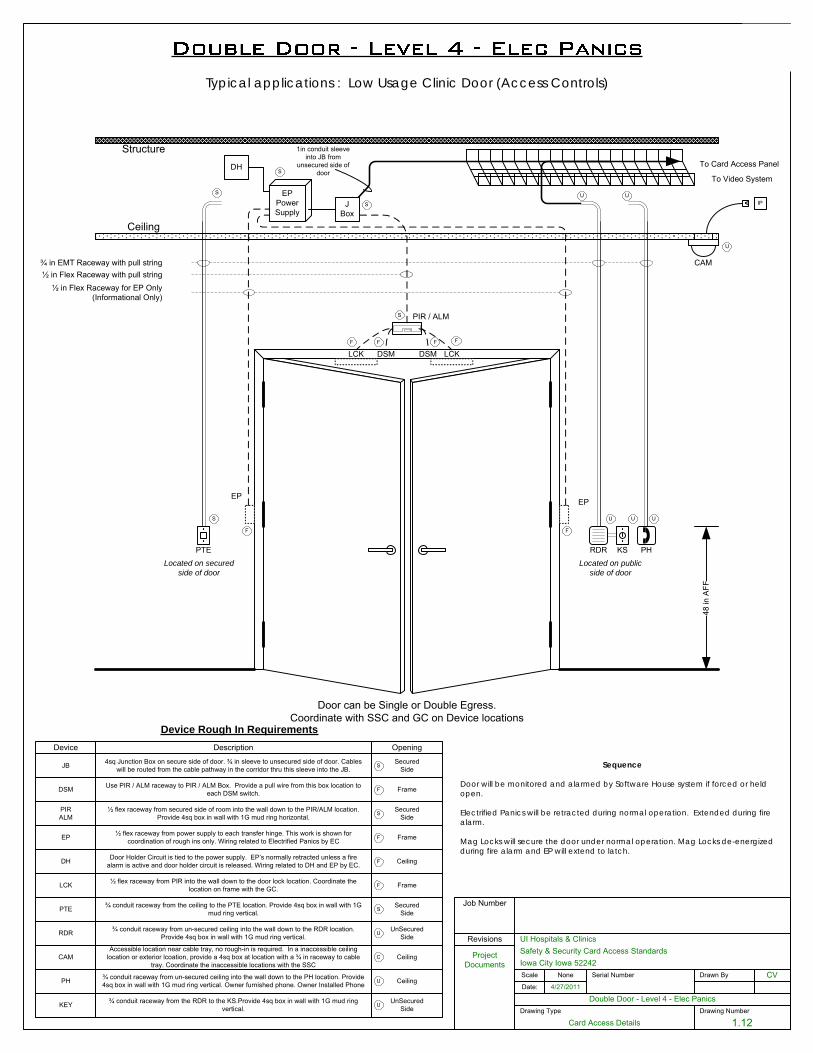
Drawing Number
1.12
Double Door - Level 4 - Elec PanicsDate:
UI Hospitals & Clinics
Iowa City Iowa 52242Scale
4/27/2011
CV
Job Number
Serial Number Drawn By
Project Documents
Revisions
Drawing Type
Card Access Details
None
Safety & Security Card Access Standards
1in conduit sleeve into JB from
unsecured side of door
Ceiling
Structure
48 in
AFF
JBox
To Card Access Panel
¾ in EMT Raceway with pull string½ in Flex Raceway with pull string
RDR
PIR / ALM
To Video System
DSM
EPEP
Located on public side of door
Device Rough In RequirementsDevice Description Opening
JB 4sq Junction Box on secure side of door. ¾ in sleeve to unsecured side of door. Cables will be routed from the cable pathway in the corridor thru this sleeve into the JB.
SecuredSideS
RDR ¾ conduit raceway from un-secured ceiling into the wall down to the RDR location. Provide 4sq box in wall with 1G mud ring vertical.
UnSecuredSideU
CAMAccessible location near cable tray, no rough-in is required. In a inaccessible ceiling
location or exterior lcoation, provide a 4sq box at location with a ¾ in raceway to cable tray. Coordinate the inaccessible locations with the SSC
CeilingC
U
F
F
F
S
S
DSM
U
Door can be Single or Double Egress.Coordinate with SSC and GC on Device locations
F
EPPowerSupply
½ in Flex Raceway for EP Only (Informational Only)
S
IP
U
CAM
DSM Use PIR / ALM raceway to PIR / ALM Box. Provide a pull wire from this box location to each DSM switch. FrameF
PIRALM
SecuredSideS
½ flex raceway from secured side of room into the wall down to the PIR/ALM location. Provide 4sq box in wall with 1G mud ring horizontal.
PH
U
U
PH ¾ conduit raceway from un-secured ceiling into the wall down to the PH location. Provide 4sq box in wall with 1G mud ring vertical. Owner furnished phone. Owner Installed Phone CeilingU
EP ½ flex raceway from power supply to each transfer hinge. This work is shown for coordination of rough ins only. Wiring related to Electrified Panics by EC FrameF
Typical applications : Low Usage Clinic Door (Access Controls)
LCK LCK
FF
LCK ½ flex raceway from PIR into the wall down to the door lock location. Coordinate the location on frame with the GC. FrameF
DH Door Holder Circuit is tied to the power supply. EP’s normally retracted unless a fire alarm is active and door holder circuit is released. Wiring related to DH and EP by EC. CeilingF
DH
PTELocated on secured
side of door
S
S
PTE SecuredSide
¾ conduit raceway from the ceiling to the PTE location. Provide 4sq box in wall with 1G mud ring vertical. S
Sequence
Door will be monitored and alarmed by Software House system if forced or held open.
Electrified Panics will be retracted during normal operation. Extended during fire alarm.
Mag Locks will secure the door under normal operation. Mag Locks de-energized during fire alarm and EP will extend to latch.
KS
U
KEY ¾ conduit raceway from the RDR to the KS.Provide 4sq box in wall with 1G mud ring vertical.
UnSecuredSideU
November 1, 2016
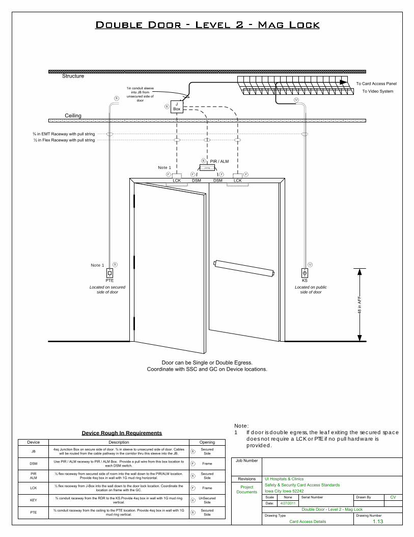
Drawing Number
1.13
Double Door - Level 2 - Mag LockDate:
UI Hospitals & Clinics
Iowa City Iowa 52242Scale
4/27/2011
CV
Job Number
Serial Number Drawn By
Project Documents
Revisions
Drawing Type
Card Access Details
None
Safety & Security Card Access Standards
1in conduit sleeve into JB from
unsecured side of door
Ceiling
Structure
48 in
AFF
JBox
To Card Access Panel
¾ in EMT Raceway with pull string½ in Flex Raceway with pull string
PIR / ALM
DSM
To Video System
DSM
PTE
LCK
KSLocated on secured
side of doorLocated on public
side of door
Device Rough In RequirementsDevice Description Opening
JB 4sq Junction Box on secure side of door. ¾ in sleeve to unsecured side of door. Cables will be routed from the cable pathway in the corridor thru this sleeve into the JB.
SecuredSideS
US
FFFF
S
S
KEY ¾ conduit raceway from the RDR to the KS.Provide 4sq box in wall with 1G mud ring vertical.
UnSecuredSideU
PTE SecuredSide
¾ conduit raceway from the ceiling to the PTE location. Provide 4sq box in wall with 1G mud ring vertical. S
LCK ½ flex raceway from J-Box into the wall down to the door lock location. Coordinate the location on frame with the GC. FrameF
DSM
S U
Door can be Single or Double Egress.Coordinate with SSC and GC on Device locations.
DSM Use PIR / ALM raceway to PIR / ALM Box. Provide a pull wire from this box location to each DSM switch. FrameF
PIRALM
SecuredSideS
½ flex raceway from secured side of room into the wall down to the PIR/ALM location. Provide 4sq box in wall with 1G mud ring horizontal.
LCK
Note:1 If door is double egress, the leaf exiting the secured space
does not require a LCK or PTE if no pull hardware is provided.
Note 1
Note 1
November 1, 2016
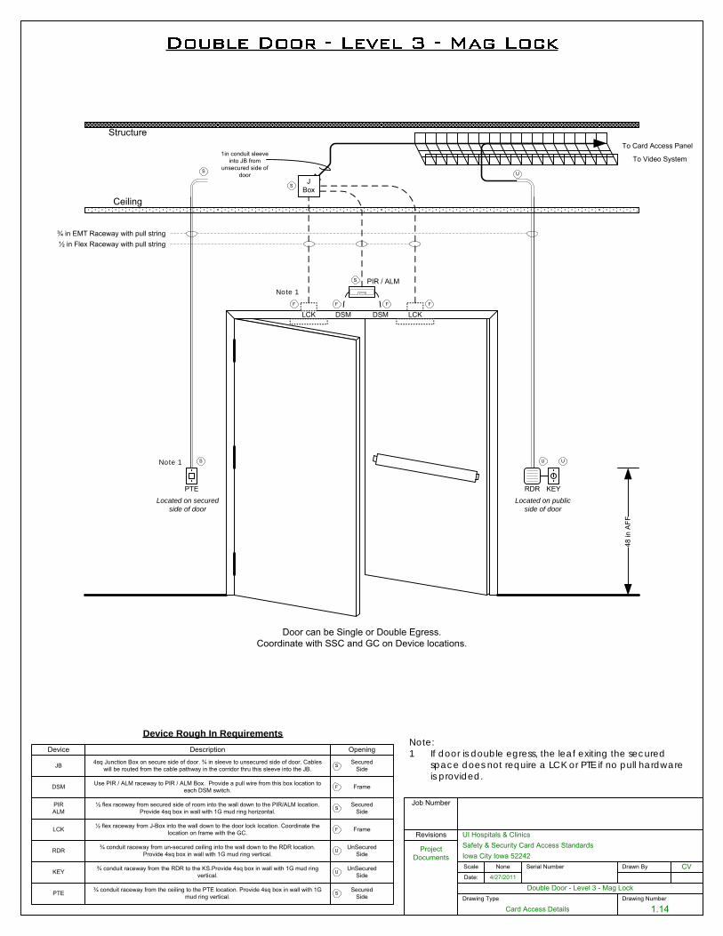
Drawing Number
1.14
Double Door - Level 3 - Mag LockDate:
UI Hospitals & Clinics
Iowa City Iowa 52242Scale
4/27/2011
CV
Job Number
Serial Number Drawn By
Project Documents
Revisions
Drawing Type
Card Access Details
None
Safety & Security Card Access Standards
1in conduit sleeve into JB from
unsecured side of door
Ceiling
Structure
48 in
AFF
JBox
To Card Access Panel
¾ in EMT Raceway with pull string½ in Flex Raceway with pull string
RDR
PIR / ALM
DSM
To Video System
DSM
PTE
LCK
KEYLocated on secured
side of doorLocated on public
side of door
Device Rough In RequirementsDevice Description Opening
JB 4sq Junction Box on secure side of door. ¾ in sleeve to unsecured side of door. Cables will be routed from the cable pathway in the corridor thru this sleeve into the JB.
SecuredSideS
RDR ¾ conduit raceway from un-secured ceiling into the wall down to the RDR location. Provide 4sq box in wall with 1G mud ring vertical.
UnSecuredSideU
U US
FFFF
S
S
KEY ¾ conduit raceway from the RDR to the KS.Provide 4sq box in wall with 1G mud ring vertical.
UnSecuredSideU
PTE SecuredSide
¾ conduit raceway from the ceiling to the PTE location. Provide 4sq box in wall with 1G mud ring vertical. S
LCK ½ flex raceway from J-Box into the wall down to the door lock location. Coordinate the location on frame with the GC. FrameF
DSM
S U
Door can be Single or Double Egress.Coordinate with SSC and GC on Device locations.
DSM Use PIR / ALM raceway to PIR / ALM Box. Provide a pull wire from this box location to each DSM switch. FrameF
PIRALM
SecuredSideS
½ flex raceway from secured side of room into the wall down to the PIR/ALM location. Provide 4sq box in wall with 1G mud ring horizontal.
LCK
Note:1 If door is double egress, the leaf exiting the secured
space does not require a LCK or PTE if no pull hardware is provided.
Note 1
Note 1
November 1, 2016
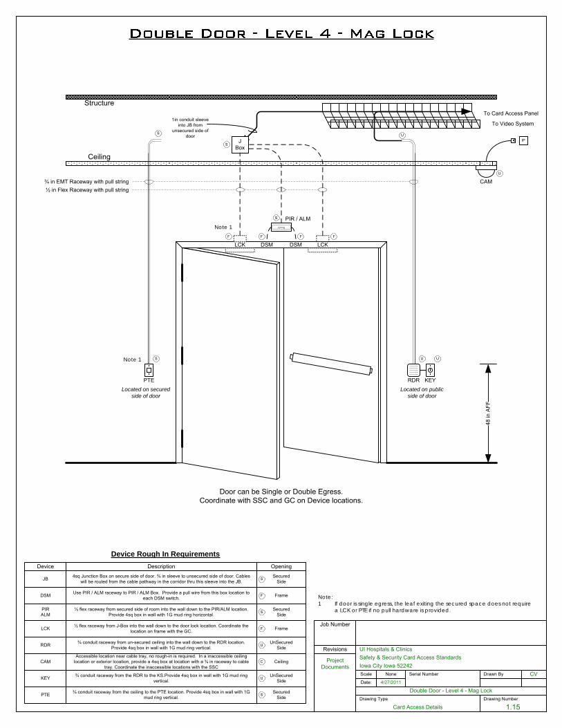
Drawing Number
1.15
Double Door - Level 4 - Mag LockDate:
UI Hospitals & Clinics
Iowa City Iowa 52242Scale
4/27/2011
CV
Job Number
Serial Number Drawn By
Project Documents
Revisions
Drawing Type
Card Access Details
None
Safety & Security Card Access Standards
1in conduit sleeve into JB from
unsecured side of door
Ceiling
Structure
48 in
AFF
JBox
To Card Access Panel
¾ in EMT Raceway with pull string½ in Flex Raceway with pull string
RDR
PIR / ALM
DSM
To Video System
DSM
PTE
LCK
KEYLocated on secured
side of doorLocated on public
side of door
Device Rough In RequirementsDevice Description Opening
JB 4sq Junction Box on secure side of door. ¾ in sleeve to unsecured side of door. Cables will be routed from the cable pathway in the corridor thru this sleeve into the JB.
SecuredSideS
RDR ¾ conduit raceway from un-secured ceiling into the wall down to the RDR location. Provide 4sq box in wall with 1G mud ring vertical.
UnSecuredSideU
CAMAccessible location near cable tray, no rough-in is required. In a inaccessible ceiling
location or exterior lcoation, provide a 4sq box at location with a ¾ in raceway to cable tray. Coordinate the inaccessible locations with the SSC
CeilingC
U US
FFFF
S
S
U
KEY ¾ conduit raceway from the RDR to the KS.Provide 4sq box in wall with 1G mud ring vertical.
UnSecuredSideU
PTE SecuredSide
¾ conduit raceway from the ceiling to the PTE location. Provide 4sq box in wall with 1G mud ring vertical. S
LCK ½ flex raceway from J-Box into the wall down to the door lock location. Coordinate the location on frame with the GC. FrameF
DSM
S U
Door can be Single or Double Egress.Coordinate with SSC and GC on Device locations.
IP
CAM
DSM Use PIR / ALM raceway to PIR / ALM Box. Provide a pull wire from this box location to each DSM switch. FrameF
PIRALM
SecuredSideS
½ flex raceway from secured side of room into the wall down to the PIR/ALM location. Provide 4sq box in wall with 1G mud ring horizontal.
LCK
Note:1 If door is single egress, the leaf exiting the secured space does not require
a LCK or PTE if no pull hardware is provided.
Note 1
Note 1
November 1, 2016
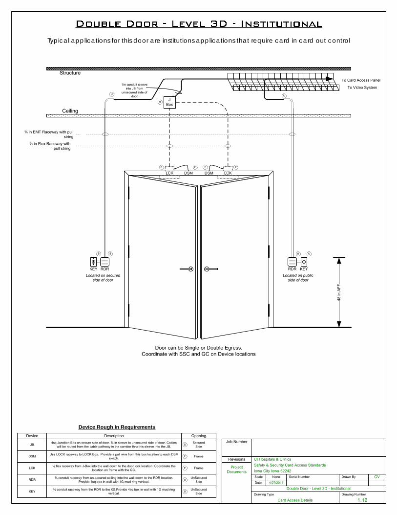
Drawing Number
1.16
Double Door - Level 3D - Institutional Date:
UI Hospitals & Clinics
Iowa City Iowa 52242Scale
4/27/2011
CV
Job Number
Serial Number Drawn By
Project Documents
Revisions
Drawing Type
Card Access Details
None
Safety & Security Card Access Standards
1in conduit sleeve into JB from
unsecured side of door
Ceiling
Structure
JBox
To Card Access Panel
¾ in EMT Raceway with pull string
½ in Flex Raceway with pull string
RDR
To Video System
DSM
KEYLocated on secured
side of doorLocated on public
side of door
Device Rough In RequirementsDevice Description Opening
JB 4sq Junction Box on secure side of door. ¾ in sleeve to unsecured side of door. Cables will be routed from the cable pathway in the corridor thru this sleeve into the JB.
SecuredSideS
RDR ¾ conduit raceway from un-secured ceiling into the wall down to the RDR location. Provide 4sq box in wall with 1G mud ring vertical.
UnSecuredSideU
U US
FFFF
S
KEY ¾ conduit raceway from the RDR to the KS.Provide 4sq box in wall with 1G mud ring vertical.
UnSecuredSideU
LCK ½ flex raceway from J-Box into the wall down to the door lock location. Coordinate the location on frame with the GC. FrameF
DSM
U U
DSM Use LOCK raceway to LOCK Box. Provide a pull wire from this box location to each DSM switch. FrameF
RDRKEY
S
48 in
AFF
Typical applications for this door are institutions applications that require card in card out control
LCKLCK
Door can be Single or Double Egress.Coordinate with SSC and GC on Device locations
November 1, 2016
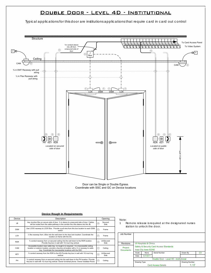
Drawing Number
1.17
Double Door - Level 4D - InstitutionalDate:
UI Hospitals & Clinics
Iowa City Iowa 52242Scale
4/27/2011
CV
Job Number
Serial Number Drawn By
Project Documents
Revisions
Drawing Type
Card Access Details
None
Safety & Security Card Access Standards
1in conduit sleeve into JB from
unsecured side of door
Ceiling
Structure
48 in
AFF
JBox
To Card Access Panel
¾ in EMT Raceway with pull string
½ in Flex Raceway with pull string
RDR
To Video System
DSM
KEYLocated on secured
side of doorLocated on public
side of door
Device Rough In RequirementsDevice Description Opening
JB 4sq Junction Box on secure side of door. ¾ in sleeve to unsecured side of door. Cables will be routed from the cable pathway in the corridor thru this sleeve into the JB.
SecuredSideS
RDR ¾ conduit raceway from un-secured ceiling into the wall down to the RDR location. Provide 4sq box in wall with 1G mud ring vertical.
UnSecuredSideU
CAMAccessible location near cable tray, no rough-in is required. In a inaccessible ceiling
location or exterior lcoation, provide a 4sq box at location with a ¾ in raceway to cable tray. Coordinate the inaccessible locations with the SSC
CeilingC
U US
FFFF
S
U
KEY ¾ conduit raceway from the RDR to the KS.Provide 4sq box in wall with 1G mud ring vertical.
UnSecuredSideU
LCK ½ flex raceway from J-Box into the wall down to the door lock location. Coordinate the location on frame with the GC. FrameF
DSM
U U
Door can be Single or Double Egress.Coordinate with SSC and GC on Device locations
IP
CAM
DSM Use LOCK raceway to LOCK Box. Provide a pull wire from this box location to each DSM switch. FrameF
RDRKEY
S US
S
IP
CAM
PH
PH ¾ conduit raceway from un-secured ceiling into the wall down to the PH location. Provide 4sq box in wall with 1G mud ring vertical. Owner furnished phone. Owner Installed Phone CeilingC
Typical applications for this door are institutions applications that require card in card out control
DSM DSM LCKLCK
PH
Note:1 Remote release is required at the designated nurses
station to unlock the door.
November 1, 2016
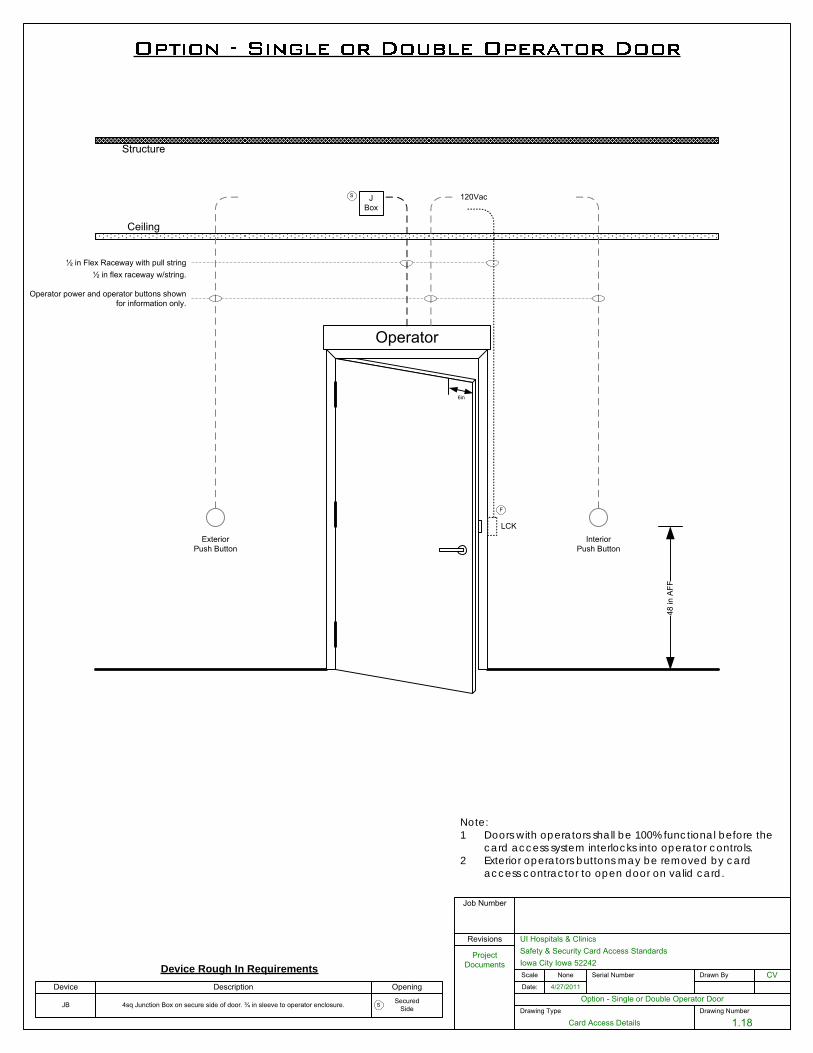
Drawing Number
1.18
Option - Single or Double Operator DoorDate:
UI Hospitals & Clinics
Iowa City Iowa 52242Scale
4/27/2011
CV
Job Number
Serial Number Drawn By
Project Documents
Revisions
Drawing Type
Card Access Details
None
Safety & Security Card Access Standards
Ceiling
Structure
Operator
JBox
½ in Flex Raceway with pull string
48 in
AFF
Operator power and operator buttons shown for information only.
120VacS
Device Rough In RequirementsDevice Description Opening
InteriorPush Button
ExteriorPush Button
JB 4sq Junction Box on secure side of door. ¾ in sleeve to operator enclosure. SecuredSideS
6in
½ in flex raceway w/string.
LCK
F
Note:1 Doors with operators shall be 100% functional before the
card access system interlocks into operator controls.2 Exterior operators buttons may be removed by card
access contractor to open door on valid card.
November 1, 2016
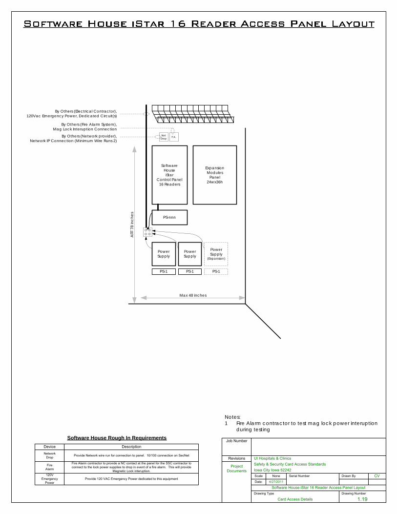
Drawing Number
1.19
Software House iStar 16 Reader Access Panel LayoutDate:
UI Hospitals & Clinics
Iowa City Iowa 52242Scale
4/27/2011
CV
Job Number
Serial Number Drawn By
Project Documents
Revisions
Drawing Type
Card Access Details
None
Safety & Security Card Access Standards
PS-1
Power Supply
SoftwareHouseiStar
Control Panel16 Readers
PS-nnn
ExpansionModules
Panel24wx36h
Max 48 inches
AFF
78
inch
es
By Others (Electrical Contractor),120Vac Emergency Power, Dedicated Circuit(s)
F.A.NetDrop
By Others (Network provider),Network IP Connection (Minimum Wire Runs 2)
PS-1
Power Supply
(Expansion)
Software House Rough In RequirementsDevice Description
FireAlarm
Fire Alarm contractor to provide a NC contact at the panel for the SSC contractor to connect to the lock power supplies to drop in event of a fire alarm. This will provide
Magnetic Lock interuption.
NetworkDrop Provide Network wire run for connection to panel. 10/100 connection on SecNet
120V Emergency
PowerProvide 120 VAC Emergency Power dedicated to this equipment
By Others (Fire Alarm System),Mag Lock Interuption Connection
Notes:1 Fire Alarm contractor to test mag lock power interuption
during testing
PS-1
Power Supply
November 1, 2016
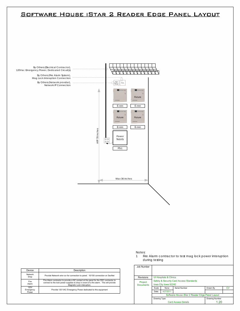
Drawing Number
1.20
Software House iStar 2 Reader Edge Panel LayoutDate:
UI Hospitals & Clinics
Iowa City Iowa 52242Scale
4/27/2011
CV
Job Number
Serial Number Drawn By
Project Documents
Revisions
Drawing Type
Card Access Details
None
Safety & Security Card Access Standards
PS-1
Power Supply
Max 36 inches
AFF
78
inch
es
By Others (Electrical Contractor),120Vac Emergency Power, Dedicated Circuit(s)
F.A.NetDrop
By Others (Network provider),Network IP Connection
Device Description
FireAlarm
Fire Alarm contractor to provide a NC contact at the panel for the SSC contractor to connect to the lock power supplies to drop in event of a fire alarm. This will provide
Magnetic Lock interuption.
NetworkDrop Provide Network wire run for connection to panel. 10/100 connection on SecNet
120V Emergency
PowerProvide 120 VAC Emergency Power dedicated to this equipment
By Others (Fire Alarm System),Mag Lock Interuption Connection
Notes:1 Fire Alarm contractor to test mag lock power interuption
during testing
E-nnn
E-nnn
E-nnn
E-nnn
Future
FutureFuture
November 1, 2016
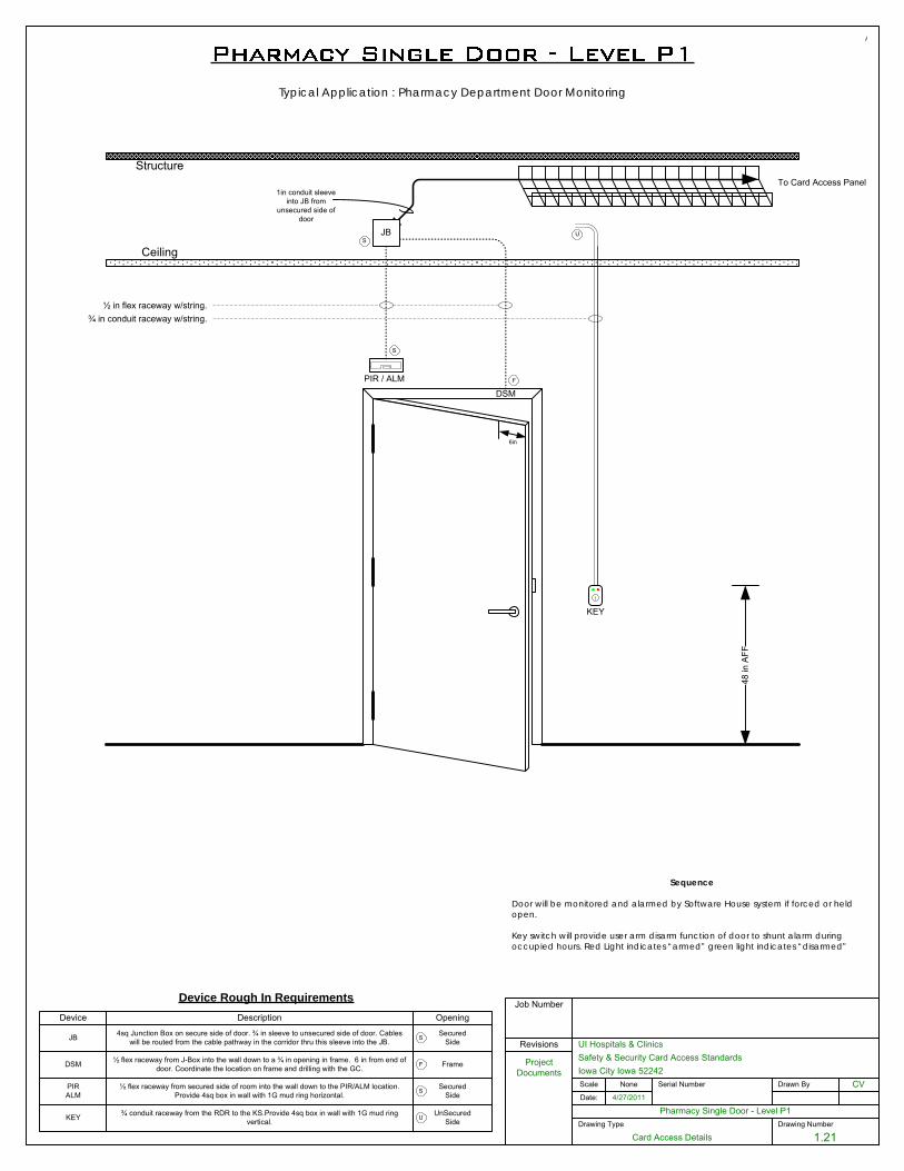
Drawing Number
1.21
Pharmacy Single Door - Level P1Date:
UI Hospitals & Clinics
Iowa City Iowa 52242Scale
4/27/2011
CV
Job Number
Serial Number Drawn By
Project Documents
Revisions
Drawing Type
Card Access Details
None
Safety & Security Card Access Standards
Ceiling
Structure
48 in
AFF
To Card Access Panel
½ in flex raceway w/string.¾ in conduit raceway w/string.
6in
DSM
Device Rough In Requirements
JB
Device Description Opening
PIR / ALM F
S
1in conduit sleeve into JB from
unsecured side of door
S
JB 4sq Junction Box on secure side of door. ¾ in sleeve to unsecured side of door. Cables will be routed from the cable pathway in the corridor thru this sleeve into the JB.
SecuredSideS
U
DSM ½ flex raceway from J-Box into the wall down to a ¾ in opening in frame. 6 in from end of door. Coordinate the location on frame and drilling with the GC. FrameF
PIRALM
SecuredSideS
½ flex raceway from secured side of room into the wall down to the PIR/ALM location. Provide 4sq box in wall with 1G mud ring horizontal.
Typical Application : Pharmacy Department Door Monitoring
KEY
KEY ¾ conduit raceway from the RDR to the KS.Provide 4sq box in wall with 1G mud ring vertical.
UnSecuredSideU
Sequence
Door will be monitored and alarmed by Software House system if forced or held open.
Key switch will provide user arm disarm function of door to shunt alarm during occupied hours. Red Light indicates “armed” green light indicates “disarmed”
November 1, 2016
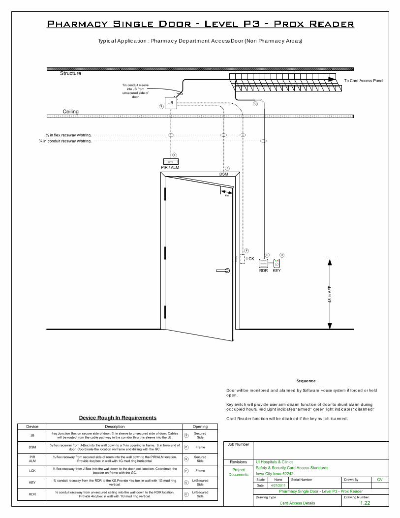
Drawing Number
1.22
Pharmacy Single Door - Level P3 - Prox ReaderDate:
UI Hospitals & Clinics
Iowa City Iowa 52242Scale
4/27/2011
CV
Job Number
Serial Number Drawn By
Project Documents
Revisions
Drawing Type
Card Access Details
None
Safety & Security Card Access Standards
Ceiling
Structure
48 in
AFF
To Card Access Panel
½ in flex raceway w/string.¾ in conduit raceway w/string.
6in
RDR
LCK
DSM
Device Rough In Requirements
JB
Device Description Opening
F
U
PIR / ALM F
S
1in conduit sleeve into JB from
unsecured side of door
S
JB 4sq Junction Box on secure side of door. ¾ in sleeve to unsecured side of door. Cables will be routed from the cable pathway in the corridor thru this sleeve into the JB.
SecuredSideS
RDR ¾ conduit raceway from un-secured ceiling into the wall down to the RDR location. Provide 4sq box in wall with 1G mud ring vertical.
UnSecuredSideU
U
DSM ½ flex raceway from J-Box into the wall down to a ¾ in opening in frame. 6 in from end of door. Coordinate the location on frame and drilling with the GC. FrameF
LCK ½ flex raceway from J-Box into the wall down to the door lock location. Coordinate the location on frame with the GC. FrameF
PIRALM
SecuredSideS
½ flex raceway from secured side of room into the wall down to the PIR/ALM location. Provide 4sq box in wall with 1G mud ring horizontal.
Typical Application : Pharmacy Department Access Door (Non Pharmacy Areas)
KEY
KEY ¾ conduit raceway from the RDR to the KS.Provide 4sq box in wall with 1G mud ring vertical.
UnSecuredSideU
U
Sequence
Door will be monitored and alarmed by Software House system if forced or held open.
Key switch will provide user arm disarm function of door to shunt alarm during occupied hours. Red Light indicates “armed” green light indicates “disarmed”
Card Reader function will be disabled if the key switch is armed.
November 1, 2016
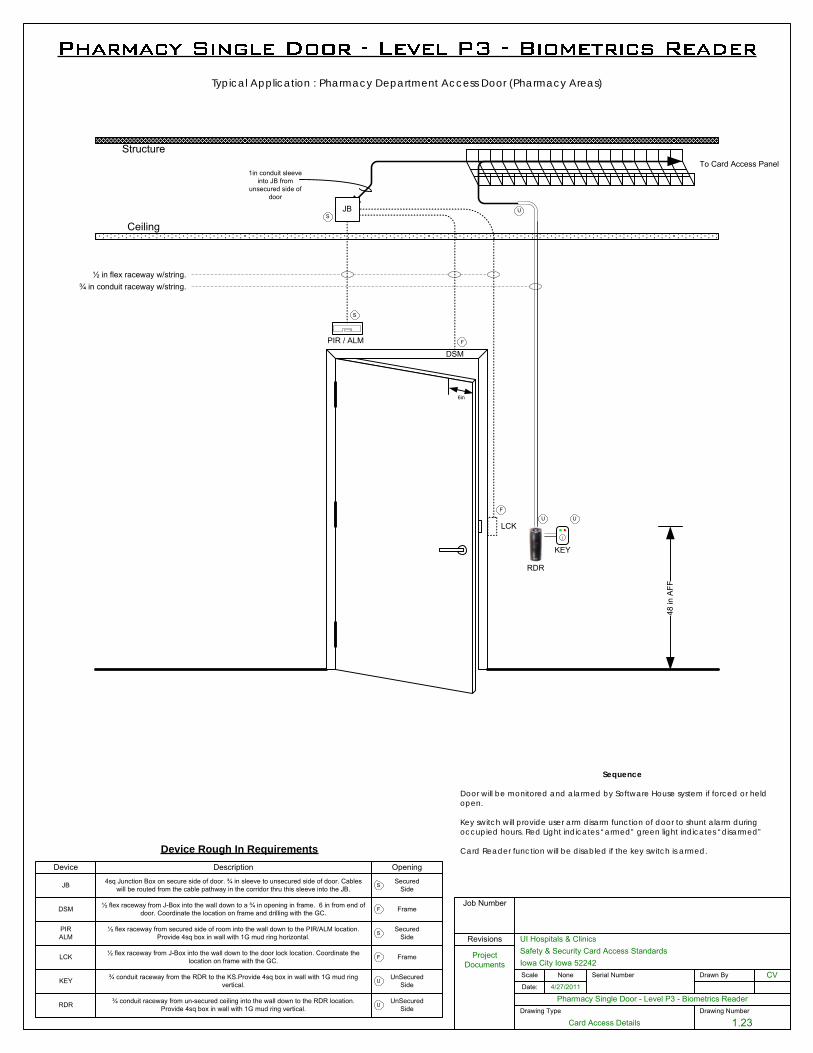
Drawing Number
1.23
Pharmacy Single Door - Level P3 - Biometrics ReaderDate:
UI Hospitals & Clinics
Iowa City Iowa 52242Scale
4/27/2011
CV
Job Number
Serial Number Drawn By
Project Documents
Revisions
Drawing Type
Card Access Details
None
Safety & Security Card Access Standards
Ceiling
Structure
48 in
AFF
To Card Access Panel
½ in flex raceway w/string.¾ in conduit raceway w/string.
6in
RDR
LCK
DSM
Device Rough In Requirements
JB
Device Description Opening
F
U
PIR / ALM F
S
1in conduit sleeve into JB from
unsecured side of door
S
JB 4sq Junction Box on secure side of door. ¾ in sleeve to unsecured side of door. Cables will be routed from the cable pathway in the corridor thru this sleeve into the JB.
SecuredSideS
RDR ¾ conduit raceway from un-secured ceiling into the wall down to the RDR location. Provide 4sq box in wall with 1G mud ring vertical.
UnSecuredSideU
U
DSM ½ flex raceway from J-Box into the wall down to a ¾ in opening in frame. 6 in from end of door. Coordinate the location on frame and drilling with the GC. FrameF
LCK ½ flex raceway from J-Box into the wall down to the door lock location. Coordinate the location on frame with the GC. FrameF
PIRALM
SecuredSideS
½ flex raceway from secured side of room into the wall down to the PIR/ALM location. Provide 4sq box in wall with 1G mud ring horizontal.
KEY
KEY ¾ conduit raceway from the RDR to the KS.Provide 4sq box in wall with 1G mud ring vertical.
UnSecuredSideU
U
Sequence
Door will be monitored and alarmed by Software House system if forced or held open.
Key switch will provide user arm disarm function of door to shunt alarm during occupied hours. Red Light indicates “armed” green light indicates “disarmed”
Card Reader function will be disabled if the key switch is armed.
Typical Application : Pharmacy Department Access Door (Pharmacy Areas)
November 1, 2016
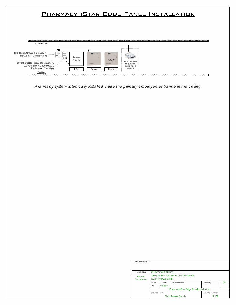
Drawing Number
1.24
Pharmacy iStar Edge Panel InstallationDate:
UI Hospitals & Clinics
Iowa City Iowa 52242Scale
4/27/2011
CV
Job Number
Serial Number Drawn By
Project Documents
Revisions
Drawing Type
Card Access Details
None
Safety & Security Card Access Standards
PS-1
Power Supply
By Others (Network provider),Network IP Connections
E-nnnCeiling
Structure
NetDrop
By Others (Electrical Contractor),120Vac Emergency Power,
Dedicated Circuit(s) E-nnn
Future485 Converter
Required if Biometrics is
present
Pharmacy system is typically installed inside the primary employee entrance in the ceiling.
November 1, 2016

Appendix M
Capital Management Design Process
November 1, 2016
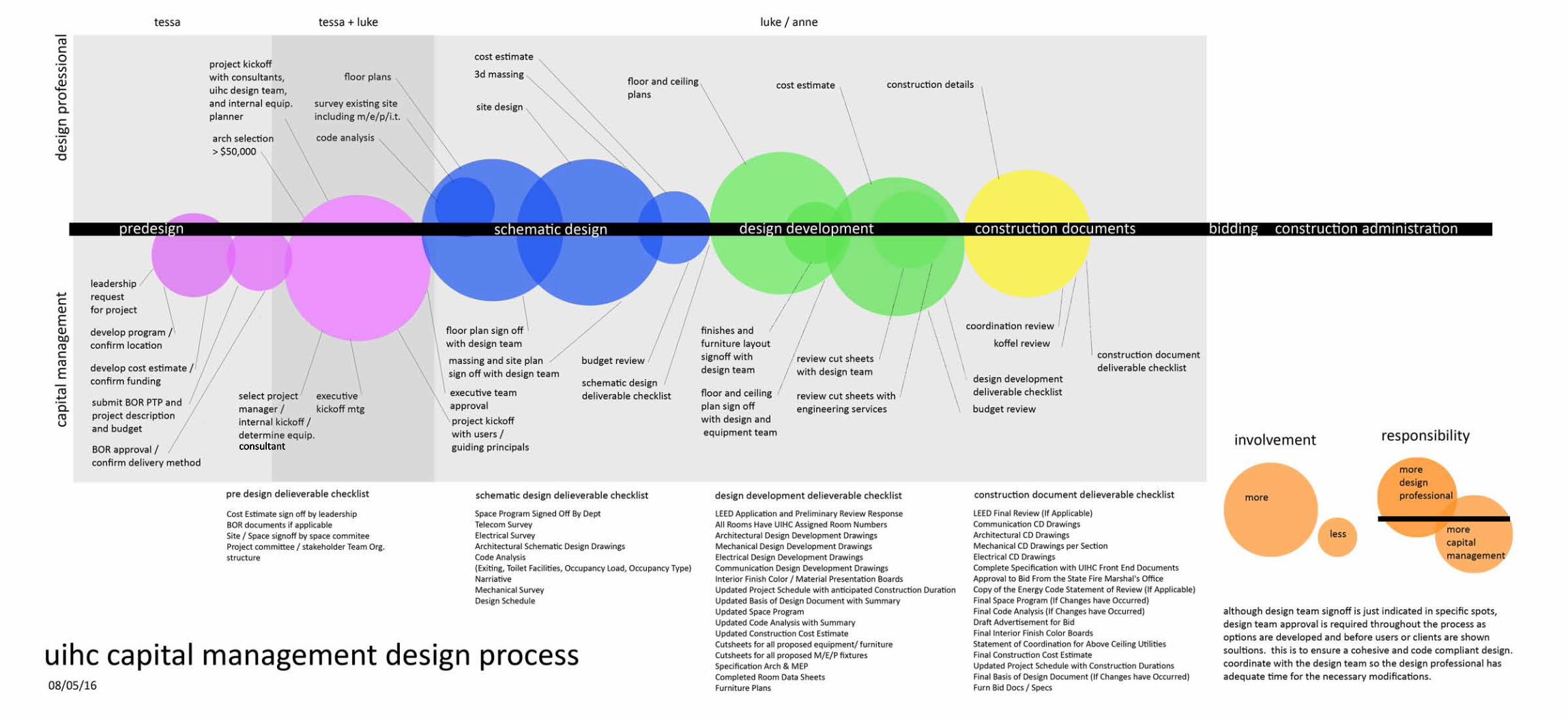
consultant
November 1, 2016