Embed Size (px)
Citation preview
Architectural Concrete
3 PDH / 3 CE Hours / 3 AIA LU/HSW
Department of the ArmyU.S. Amy Corps of Engineers
PDH AcademyPO Box 449
Pewaukee, WI 53072
888-564-9098
3ARCHITECTURE |
Architectural Concrete Final Exam 1. Regarding Crack control (cast-in-place), due
to _________________, stresses are produced in structural concrete where restraint occurs and cracks may develop.
a. sub-zero temperatures b. natural drying shrinkage of concrete c. uneven loading d. heat
2. Considering Materials and economics, selection of forms for architectural concrete is not only determined by the __________ desired but by the number of expected reuses, form installation, form removal, and use of form ties.
a. texture b. strength c. color d. thickness
3. The architect’s selection of the pattern or texture may determine the type of:
a. concrete b. plasticizers c. colorant d. form material
4. With respect to Concrete Material and Proportions, the _______ used for architectural concrete must come from the same source for the duration of the project to prevent major changes in color.
a. aggregate b. cement c. plasticizers d. form release agent
5. For Concrete Placement, most specifications require layers to be held to heights less than:
a. 0.2 m (8 in.) b. 0.4 m (16 in.) c. 0.6 m (24 in.) d. 0.8 m (32 in.)
6. Exposure of aggregate by ___________ is the general method of exposing aggregate in precast and cast-in-place flatwork.
a. acid etching b. sand blasting c. wire brushing d. water brushing
7. Bush hammering __________ by fracturing the surface of the concrete through impact of a pneumatically driven tool with steel teeth.
a. crushes the aggregate b. exposes the aggregate c. removes imperfections d. alters the color
8. The fractured rib texture requires: a. crushed aggregate b. metal forms c. an as-cast ribbed finish initially d. adding colorant to the release agent
9. With regards to Protective Coatings, many coatings are __________ and should be tested on the field mockup for yellowing, chalking, and effect on concrete color and texture.
a. acidic b. abrasive c. proprietary d. generic
10. The architectural treatment of concrete may become an important issue when the structure is located:
a. in the southwest United States b. in a populated area or in a tourist site c. in an industrial setting d. within a TIF district

Moisture-Resistant Homes ARCHITECTURE|84
4.4 IN CONCLUSIONThis guide arms you with information that can significantly assist in the protection of your biggest investment – your home.
As you can tell by having looked through this handbook, simple observations and inspections can help protect against:
• the deterioration of your home’s value
• personal property loss
• structural damage caused by water
Developing good home maintenance habits, taking quick action when water damage occurs, making timely repairs, and thoroughly removing excess moisture from your home will help minimize your repair costs and future moisture concerns. A well-constructed and well-maintained home will protect your family and belongings for a very long time.
Resources
Whether you plan to hire a contractor for necessary repairs or improvements, you plan to do work yourself, or you’re just interested in learning more about home moisture management, there are a number of excellent resources available to you.
Consumer Directed Resources
We all want to live in and maintain healthy houses. The more you know, the better you’ll feel.
HUD Healthy Homes http://170.97.67.13/offices/lead/hhi/consumer. cfm
FEMA “Repairing Your Flooded Home” www.fema.gov/hazards/floods/lib234.shtm
GLE Associates, Inc. www.gleassociates.com/mold
Environmental Protection Agency “A Brief Guide to Mold, Moisture and Your Home” www.epa.gov/iaq
For Homeowners Working with Contractors Want help checking out a contractor before hiring or having a home improvement contract reviewed; or learning what a good home improvement contract includes? Start here. Smart Consumer Services www.SmartConsumerServices.org
|ARCHITECTURE Architectural Concrete 85
Architectural Concrete
AIA CES Course Number: AIAPDH133
Course Description:This course provides guidance for the design and construction of architectural concrete, including planning and design, forms, materials and proportions, batching and transporting, placement, curing and form removal, exposed aggregate surfaces, finishing, and quality assurance. Course material is from the U.S. Army Corps of Engineers, Manual 1110-1-2009.
Learning Units:3.0 LU/HSW
Learning Objective 1:Upon completion of this course, the student will understand the structural design parameters that are essential in architectural concrete construction and that must be addressed by the designer.
Learning Objective 2:The student will learn many of the techniques used to obtain various finishes and appearances as well as how to specify them.
Learning Objective 3:The student will understand specific material batching and concrete placement techniques and how these affect the final appearance.
Learning Objective 4:The student will know how defects should be repaired and will be aware of final finishing techniques.
EM 1110-1-2009DEPARTMENT OF THE ARMYU.S. Army Corps of EngineersWashington, DC 20314-1000
Manual No. 1110-1-2009 31 October 1997
Engineering and DesignARCHITECTURAL CONCRETE

Architectural Concrete ARCHITECTURE|86
CHAPTER 1 – GENERAL
1-1. Purpose and Scope
This manual provides guidance for the design and construction of architectural concrete, including planning and design, forms, materials and proportions, batching and transporting, placement, curing and form removal, exposed aggregate surfaces, finishing, and quality assurance.
1-2. Applicability
This manual applies to all HQUSACE elements and all field operating activities (FOA) having civil works and/or military programs responsibility.
1-3. References
References cited in this manual are listed in Appendix A.
1-4. Distribution Statement
Approved for public release, distribution is unlimited.
1-5. Definition-Architectural Concrete
The American Concrete Institute (ACI) defines architectural concrete as concrete exposed as an interior or exterior surface in the completed structure.
1-6. Specifications
Specifications can be performance type, where the quality of the end product is specified or prescription type, where methods, materials, and procedures are specified. The performance type requires the contractor to be entirely responsible for the quality of the end product. The prescription type requires acceptance of the completed product if the contractor has followed the specifications. An architectural concrete specification is usually a combination of both.
1-7. Drawings
Architectural concrete contributes to the visual character of the structure and must be designated as such in the contract drawings and specifications. All surfaces to have an architectural concrete appearance must be labeled on the contract drawings in order to prevent controversy during construction. This includes limits, location, and type of treatment.
CHAPTER 2 – PLANNING AND DESIGN CRITERIA
2-1. Structural Guidelines
This chapter delineates structural design parameters that are essential in architectural concrete construction and must be addressed by the designer. These parameters emphasize the need for designs that are in excess of those for structural concrete construction.
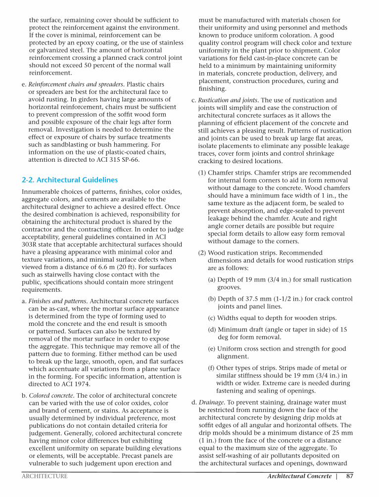
a. Crack control (cast-in-place). Due to natural drying shrinkage of concrete, stresses are produced in structural concrete where restraint occurs and cracks may develop. In as-cast finishes, cracks are of minor importance when sufficient reinforcement is used to hold them to fine widths. Surfaces to be sandblasted for treatment cannot tolerate any cracking, as the sandblasting tends to widen very fine cracks or accentuate discernible cracks. To minimize visible cracking, sufficiently deep rustication joints can be placed at regular intervals to draw the cracking where sealants can be used to seal against leaking and conceal the cracking. Placement of concrete can be limited by section in long walls to allow for the anticipated volume changes. The recommended maximum spacing of vertical construction joints for a wall placement is 60 ft and the recommended vertical contraction joint spacing is as follows:
Wall height Vertical contraction joint spacing
0.6-2.4 m (2-8 ft) 3 times wall height
2.4-3.7 m (8-12 ft) 2 times wall height
>3.7 m (12 ft) 1 time wall height
b. Crack control-(precast). Precast architectural units should have some flexibility after erection to allow for distortions due to temperature and shrinkage and movements of the building’s structural frame without cracking.
c. Deflections. Architectural concrete requires more rigid control of deflections for long span smooth concrete girders to prevent an appearance known as “optical sag.” As limitations are determined by personal preference, deflections should be minimized by overcorrection of the camber needed to offset the total deflection. Total deflection is the sum of all individual computed deflections due to all loadings plus those due to time-dependent effects. Specific information is given in ACI 435R-95 (ACI 1995b).
d. Reinforcement. Sufficient reinforcement is required at window corners and other openings to prevent the formation of cracking. Horizontal steel in walls should be increased 50 percent above the ACI 318 (ACI 1995a) minimum requirements. Where rustication is used or aggregate is to be exposed on
|ARCHITECTURE Architectural Concrete 87
the surface, remaining cover should be sufficient to protect the reinforcement against the environment. If the cover is minimal, reinforcement can be protected by an epoxy coating, or the use of stainless or galvanized steel. The amount of horizontal reinforcement crossing a planned crack control joint should not exceed 50 percent of the normal wall reinforcement.
e. Reinforcement chairs and spreaders. Plastic chairs or spreaders are best for the architectural face to avoid rusting. In girders having large amounts of horizontal reinforcement, chairs must be sufficient to prevent compression of the soffit wood form and possible exposure of the chair legs after form removal. Investigation is needed to determine the effect or exposure of chairs by surface treatments such as sandblasting or bush hammering. For information on the use of plastic-coated chairs, attention is directed to ACI 315 SP-66.
2-2. Architectural Guidelines
Innumerable choices of patterns, finishes, color oxides, aggregate colors, and cements are available to the architectural designer to achieve a desired effect. Once the desired combination is achieved, responsibility for obtaining the architectural product is shared by the contractor and the contracting officer. In order to judge acceptability, general guidelines contained in ACI 303R state that acceptable architectural surfaces should have a pleasing appearance with minimal color and texture variations, and minimal surface defects when viewed from a distance of 6.6 m (20 ft). For surfaces such as stairwells having close contact with the public, specifications should contain more stringent requirements.
a. Finishes and patterns. Architectural concrete surfaces can be as-cast, where the mortar surface appearance is determined from the type of forming used to mold the concrete and the end result is smooth or patterned. Surfaces can also be textured by removal of the mortar surface in order to expose the aggregate. This technique may remove all of the pattern due to forming. Either method can be used to break up the large, smooth, open, and flat surfaces which accentuate all variations from a plane surface in the forming. For specific information, attention is directed to ACI 1974.
b. Colored concrete. The color of architectural concrete can be varied with the use of color oxides, color and brand of cement, or stains. As acceptance is usually determined by individual preference, most publications do not contain detailed criteria for judgement. Generally, colored architectural concrete having minor color differences but exhibiting excellent uniformity on separate building elevations or elements, will be acceptable. Precast panels are vulnerable to such judgement upon erection and
must be manufactured with materials chosen for their uniformity and using personnel and methods known to produce uniform coloration. A good quality control program will check color and texture uniformity in the plant prior to shipment. Color variations for field cast-in-place concrete can be held to a minimum by maintaining uniformity in materials, concrete production, delivery, and placement, construction procedures, curing and finishing.
c. Rustication and joints. The use of rustication and joints will simplify and ease the construction of architectural concrete surfaces as it allows the planning of efficient placement of the concrete and still achieves a pleasing result. Patterns of rustication and joints can be used to break up large flat areas, isolate placements to eliminate any possible leakage traces, cover form joints and control shrinkage cracking to desired locations.
(1) Chamfer strips. Chamfer strips are recommended for internal form corners to aid in form removal without damage to the concrete. Wood chamfers should have a minimum face width of 1 in., the same texture as the adjacent form, be sealed to prevent absorption, and edge-sealed to prevent leakage behind the chamfer. Acute and right angle corner details are possible but require special form details to allow easy form removal without damage to the corners.
(2) Wood rustication strips. Recommended dimensions and details for wood rustication strips are as follows:
(a) Depth of 19 mm (3/4 in.) for small rustication grooves.
(b) Depth of 37.5 mm (1-1/2 in.) for crack control joints and panel lines.
(c) Widths equal to depth for wooden strips.
(d) Minimum draft (angle or taper in side) of 15 deg for form removal.
(e) Uniform cross section and strength for good alignment.
(f) Other types of strips. Strips made of metal or similar stiffness should be 19 mm (3/4 in.) in width or wider. Extreme care is needed during fastening and sealing of openings.
d. Drainage. To prevent staining, drainage water must be restricted from running down the face of the architectural concrete by designing drip molds at soffit edges of all angular and horizontal offsets. The drip molds should be a minimum distance of 25 mm (1 in.) from the face of the concrete or a distance equal to the maximum size of the aggregate. To assist self-washing of air pollutants deposited on the architectural surfaces and openings, downward
Architectural Concrete ARCHITECTURE|86
CHAPTER 1 – GENERAL
1-1. Purpose and Scope
This manual provides guidance for the design and construction of architectural concrete, including planning and design, forms, materials and proportions, batching and transporting, placement, curing and form removal, exposed aggregate surfaces, finishing, and quality assurance.
1-2. Applicability
This manual applies to all HQUSACE elements and all field operating activities (FOA) having civil works and/or military programs responsibility.
1-3. References
References cited in this manual are listed in Appendix A.
1-4. Distribution Statement
Approved for public release, distribution is unlimited.
1-5. Definition-Architectural Concrete
The American Concrete Institute (ACI) defines architectural concrete as concrete exposed as an interior or exterior surface in the completed structure.
1-6. Specifications
Specifications can be performance type, where the quality of the end product is specified or prescription type, where methods, materials, and procedures are specified. The performance type requires the contractor to be entirely responsible for the quality of the end product. The prescription type requires acceptance of the completed product if the contractor has followed the specifications. An architectural concrete specification is usually a combination of both.
1-7. Drawings
Architectural concrete contributes to the visual character of the structure and must be designated as such in the contract drawings and specifications. All surfaces to have an architectural concrete appearance must be labeled on the contract drawings in order to prevent controversy during construction. This includes limits, location, and type of treatment.
CHAPTER 2 – PLANNING AND DESIGN CRITERIA
2-1. Structural Guidelines
This chapter delineates structural design parameters that are essential in architectural concrete construction and must be addressed by the designer. These parameters emphasize the need for designs that are in excess of those for structural concrete construction.
a. Crack control (cast-in-place). Due to natural drying shrinkage of concrete, stresses are produced in structural concrete where restraint occurs and cracks may develop. In as-cast finishes, cracks are of minor importance when sufficient reinforcement is used to hold them to fine widths. Surfaces to be sandblasted for treatment cannot tolerate any cracking, as the sandblasting tends to widen very fine cracks or accentuate discernible cracks. To minimize visible cracking, sufficiently deep rustication joints can be placed at regular intervals to draw the cracking where sealants can be used to seal against leaking and conceal the cracking. Placement of concrete can be limited by section in long walls to allow for the anticipated volume changes. The recommended maximum spacing of vertical construction joints for a wall placement is 60 ft and the recommended vertical contraction joint spacing is as follows:
Wall height Vertical contraction joint spacing
0.6-2.4 m (2-8 ft) 3 times wall height
2.4-3.7 m (8-12 ft) 2 times wall height
>3.7 m (12 ft) 1 time wall height
b. Crack control-(precast). Precast architectural units should have some flexibility after erection to allow for distortions due to temperature and shrinkage and movements of the building’s structural frame without cracking.
c. Deflections. Architectural concrete requires more rigid control of deflections for long span smooth concrete girders to prevent an appearance known as “optical sag.” As limitations are determined by personal preference, deflections should be minimized by overcorrection of the camber needed to offset the total deflection. Total deflection is the sum of all individual computed deflections due to all loadings plus those due to time-dependent effects. Specific information is given in ACI 435R-95 (ACI 1995b).
d. Reinforcement. Sufficient reinforcement is required at window corners and other openings to prevent the formation of cracking. Horizontal steel in walls should be increased 50 percent above the ACI 318 (ACI 1995a) minimum requirements. Where rustication is used or aggregate is to be exposed on
|ARCHITECTURE Architectural Concrete 87
the surface, remaining cover should be sufficient to protect the reinforcement against the environment. If the cover is minimal, reinforcement can be protected by an epoxy coating, or the use of stainless or galvanized steel. The amount of horizontal reinforcement crossing a planned crack control joint should not exceed 50 percent of the normal wall reinforcement.
e. Reinforcement chairs and spreaders. Plastic chairs or spreaders are best for the architectural face to avoid rusting. In girders having large amounts of horizontal reinforcement, chairs must be sufficient to prevent compression of the soffit wood form and possible exposure of the chair legs after form removal. Investigation is needed to determine the effect or exposure of chairs by surface treatments such as sandblasting or bush hammering. For information on the use of plastic-coated chairs, attention is directed to ACI 315 SP-66.
2-2. Architectural Guidelines
Innumerable choices of patterns, finishes, color oxides, aggregate colors, and cements are available to the architectural designer to achieve a desired effect. Once the desired combination is achieved, responsibility for obtaining the architectural product is shared by the contractor and the contracting officer. In order to judge acceptability, general guidelines contained in ACI 303R state that acceptable architectural surfaces should have a pleasing appearance with minimal color and texture variations, and minimal surface defects when viewed from a distance of 6.6 m (20 ft). For surfaces such as stairwells having close contact with the public, specifications should contain more stringent requirements.
a. Finishes and patterns. Architectural concrete surfaces can be as-cast, where the mortar surface appearance is determined from the type of forming used to mold the concrete and the end result is smooth or patterned. Surfaces can also be textured by removal of the mortar surface in order to expose the aggregate. This technique may remove all of the pattern due to forming. Either method can be used to break up the large, smooth, open, and flat surfaces which accentuate all variations from a plane surface in the forming. For specific information, attention is directed to ACI 1974.
b. Colored concrete. The color of architectural concrete can be varied with the use of color oxides, color and brand of cement, or stains. As acceptance is usually determined by individual preference, most publications do not contain detailed criteria for judgement. Generally, colored architectural concrete having minor color differences but exhibiting excellent uniformity on separate building elevations or elements, will be acceptable. Precast panels are vulnerable to such judgement upon erection and
must be manufactured with materials chosen for their uniformity and using personnel and methods known to produce uniform coloration. A good quality control program will check color and texture uniformity in the plant prior to shipment. Color variations for field cast-in-place concrete can be held to a minimum by maintaining uniformity in materials, concrete production, delivery, and placement, construction procedures, curing and finishing.
c. Rustication and joints. The use of rustication and joints will simplify and ease the construction of architectural concrete surfaces as it allows the planning of efficient placement of the concrete and still achieves a pleasing result. Patterns of rustication and joints can be used to break up large flat areas, isolate placements to eliminate any possible leakage traces, cover form joints and control shrinkage cracking to desired locations.
(1) Chamfer strips. Chamfer strips are recommended for internal form corners to aid in form removal without damage to the concrete. Wood chamfers should have a minimum face width of 1 in., the same texture as the adjacent form, be sealed to prevent absorption, and edge-sealed to prevent leakage behind the chamfer. Acute and right angle corner details are possible but require special form details to allow easy form removal without damage to the corners.
(2) Wood rustication strips. Recommended dimensions and details for wood rustication strips are as follows:
(a) Depth of 19 mm (3/4 in.) for small rustication grooves.
(b) Depth of 37.5 mm (1-1/2 in.) for crack control joints and panel lines.
(c) Widths equal to depth for wooden strips.
(d) Minimum draft (angle or taper in side) of 15 deg for form removal.
(e) Uniform cross section and strength for good alignment.
(f) Other types of strips. Strips made of metal or similar stiffness should be 19 mm (3/4 in.) in width or wider. Extreme care is needed during fastening and sealing of openings.
d. Drainage. To prevent staining, drainage water must be restricted from running down the face of the architectural concrete by designing drip molds at soffit edges of all angular and horizontal offsets. The drip molds should be a minimum distance of 25 mm (1 in.) from the face of the concrete or a distance equal to the maximum size of the aggregate. To assist self-washing of air pollutants deposited on the architectural surfaces and openings, downward
Architectural Concrete ARCHITECTURE|88
slopes should be provided on sills and top surfaces of projecting details. Upward slopes should be provided for the upper surfaces of recesses. Such slopes can be 1:12 for smooth surfaces to 1:1 for textures. Rainwater should be directed away from the architectural face on the upper surfaces of parapets.
2-3. Design Reference Sample and Mockups
In order to properly specify and construct an architectural concrete structure, use of the design reference sample and mockup can lead to proper decisions during the bidding and construction stages. For some projects, the mockup may become an interior wall which is to be eventually covered. All projects incorporating architectural concrete should have an acceptable sample mockup constructed by the contractor’s forces for control purposes. Architectural specifications should state that no architectural production forming will be constructed until a completed mockup has been approved.
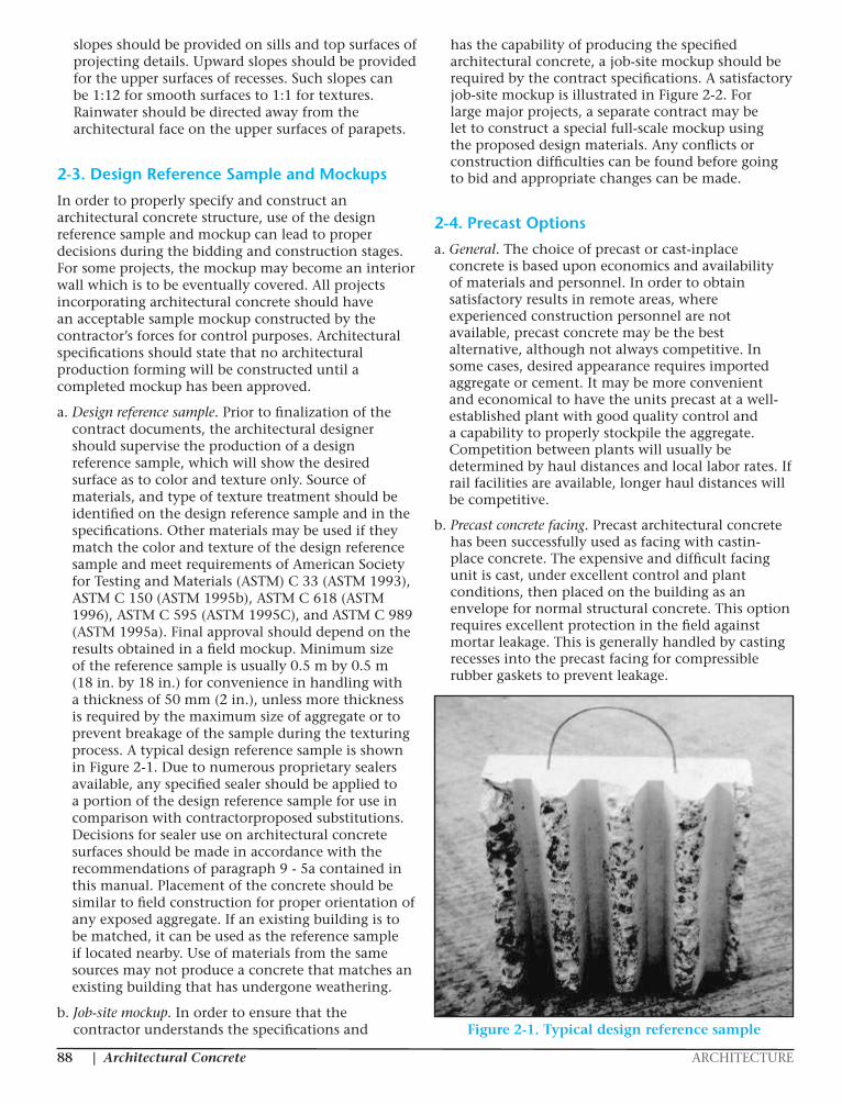
a. Design reference sample. Prior to finalization of the contract documents, the architectural designer should supervise the production of a design reference sample, which will show the desired surface as to color and texture only. Source of materials, and type of texture treatment should be identified on the design reference sample and in the specifications. Other materials may be used if they match the color and texture of the design reference sample and meet requirements of American Society for Testing and Materials (ASTM) C 33 (ASTM 1993), ASTM C 150 (ASTM 1995b), ASTM C 618 (ASTM 1996), ASTM C 595 (ASTM 1995C), and ASTM C 989 (ASTM 1995a). Final approval should depend on the results obtained in a field mockup. Minimum size of the reference sample is usually 0.5 m by 0.5 m (18 in. by 18 in.) for convenience in handling with a thickness of 50 mm (2 in.), unless more thickness is required by the maximum size of aggregate or to prevent breakage of the sample during the texturing process. A typical design reference sample is shown in Figure 2-1. Due to numerous proprietary sealers available, any specified sealer should be applied to a portion of the design reference sample for use in comparison with contractorproposed substitutions. Decisions for sealer use on architectural concrete surfaces should be made in accordance with the recommendations of paragraph 9 - 5a contained in this manual. Placement of the concrete should be similar to field construction for proper orientation of any exposed aggregate. If an existing building is to be matched, it can be used as the reference sample if located nearby. Use of materials from the same sources may not produce a concrete that matches an existing building that has undergone weathering.
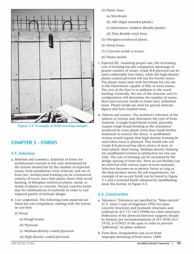
b. Job-site mockup. In order to ensure that the contractor understands the specifications and
has the capability of producing the specified architectural concrete, a job-site mockup should be required by the contract specifications. A satisfactory job-site mockup is illustrated in Figure 2-2. For large major projects, a separate contract may be let to construct a special full-scale mockup using the proposed design materials. Any conflicts or construction difficulties can be found before going to bid and appropriate changes can be made.
2-4. Precast Options
a. General. The choice of precast or cast-inplace concrete is based upon economics and availability of materials and personnel. In order to obtain satisfactory results in remote areas, where experienced construction personnel are not available, precast concrete may be the best alternative, although not always competitive. In some cases, desired appearance requires imported aggregate or cement. It may be more convenient and economical to have the units precast at a well-established plant with good quality control and a capability to properly stockpile the aggregate. Competition between plants will usually be determined by haul distances and local labor rates. If rail facilities are available, longer haul distances will be competitive.
b. Precast concrete facing. Precast architectural concrete has been successfully used as facing with castin- place concrete. The expensive and difficult facing unit is cast, under excellent control and plant conditions, then placed on the building as an envelope for normal structural concrete. This option requires excellent protection in the field against mortar leakage. This is generally handled by casting recesses into the precast facing for compressible rubber gaskets to prevent leakage.
EM 1110-1-200931 Oct 97
2-4
Figure 2-1. Typical design reference sampleFigure 2-1. Typical design reference sample
|ARCHITECTURE Architectural Concrete 89
EM 1110-1-200931 Oct 97
2-5
Figure 2-2. Example of field mockup sampleFigure 2-2. Example of field mockup sample
CHAPTER 3 – FORMS
3-1. Selection
a. Materials and economics. Selection of forms for architectural concrete is not only determined by the texture desired but by the number of expected reuses, form installation, form removal, and use of form ties. Architectural forming can be constructed entirely of wood, have thin plastic liners with wood backing, of fiberglass reinforced plastic, metal, or molds of plaster or concrete. Precast concrete forms may be combinations of materials in order to cast required panels of intricate design.
b. Cost comparison. The following form materials are listed for cost comparison, starting with the lowest in cost first:
(l) Wood.
(a) Rough board.
(b) Plywood.
(c) Medium-density coated plywood.
(d) High-density coated plywood.
(2) Plastic liner.
(a) Styrofoam.
(b) ABS (Rigid extruded plastic).
(c) Elastomeric (rubbery flexible plastic).
(d) Thin flexible vinyl liner.
(3) Fiberglass-reinforced plastic.
(4) Metal forms.
(5) Concrete molds or forms.
(6) Plaster molds.
c. Expected life. Assuming proper care, the increasing cost of forming has the companion advantage of greater number of reuses. Grade B-B plywood can be used comfortably four times, while the high-density plastic-coated plywood will last for twenty reuses. The plastic liners start with Styrofoam for one use to the Elastomeric capable of fifty or more reuses. The cost of the liner is in addition to the wood backing. Generally, the size of the structure and its configuration will determine the number of reuses. Steel and concrete molds or forms have unlimited reuse. Plaster molds are used for special intricate figures and have limited reuse.
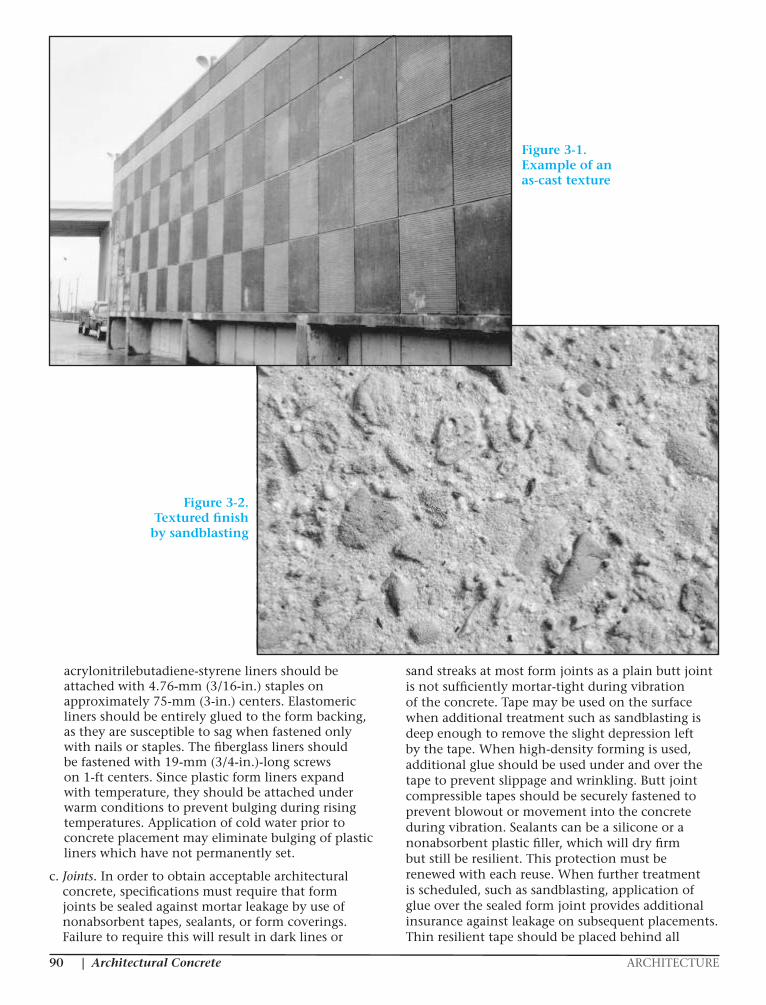
d. Patterns and textures. The architect's selection of the pattern or texture may determine the type of form material. A rough board finish would, generally, require rough board forming as the simulation produced by some plastic form liner needs further treatment to remove the sheen. A sandblasted texture would require that high-density forming be used when reuse is planned. This would rule out Grade B-B plywood but allow choice of steel, or vinyl plastic sheet lining. Medium-density forming for sandblasted textures is satisfactory for one use only. The cost of forming can be increased by the design spacing of form ties. Most as-cast finishes can be achieved with various types of form materials. Selection becomes an economic factor as long as the final product meets the job requirements. An example of an as-cast finish can be found in Figure 3-1 and a textured finish obtained by sandblasting away the mortar, in Figure 3-2.
3-2. Construction
a. Tolerances. Tolerances are specified in “Mass oncrete” (U.S. Army Corps of Engineers 1992) for mass concrete structures and hydraulic structures and outlined in ACI 117 (ACI 1990b) for other structures. Deflection of the plywood between supports should be limited, per recommendations of ACI 303R (ACI 1974), to 0.0025 of the span in order to prevent “pillowing” on plane surfaces.
b. Form liners. Irregularities can occur from improper fastening of form liners. (ABS)
Architectural Concrete ARCHITECTURE|88
slopes should be provided on sills and top surfaces of projecting details. Upward slopes should be provided for the upper surfaces of recesses. Such slopes can be 1:12 for smooth surfaces to 1:1 for textures. Rainwater should be directed away from the architectural face on the upper surfaces of parapets.
2-3. Design Reference Sample and Mockups
In order to properly specify and construct an architectural concrete structure, use of the design reference sample and mockup can lead to proper decisions during the bidding and construction stages. For some projects, the mockup may become an interior wall which is to be eventually covered. All projects incorporating architectural concrete should have an acceptable sample mockup constructed by the contractor’s forces for control purposes. Architectural specifications should state that no architectural production forming will be constructed until a completed mockup has been approved.
a. Design reference sample. Prior to finalization of the contract documents, the architectural designer should supervise the production of a design reference sample, which will show the desired surface as to color and texture only. Source of materials, and type of texture treatment should be identified on the design reference sample and in the specifications. Other materials may be used if they match the color and texture of the design reference sample and meet requirements of American Society for Testing and Materials (ASTM) C 33 (ASTM 1993), ASTM C 150 (ASTM 1995b), ASTM C 618 (ASTM 1996), ASTM C 595 (ASTM 1995C), and ASTM C 989 (ASTM 1995a). Final approval should depend on the results obtained in a field mockup. Minimum size of the reference sample is usually 0.5 m by 0.5 m (18 in. by 18 in.) for convenience in handling with a thickness of 50 mm (2 in.), unless more thickness is required by the maximum size of aggregate or to prevent breakage of the sample during the texturing process. A typical design reference sample is shown in Figure 2-1. Due to numerous proprietary sealers available, any specified sealer should be applied to a portion of the design reference sample for use in comparison with contractorproposed substitutions. Decisions for sealer use on architectural concrete surfaces should be made in accordance with the recommendations of paragraph 9 - 5a contained in this manual. Placement of the concrete should be similar to field construction for proper orientation of any exposed aggregate. If an existing building is to be matched, it can be used as the reference sample if located nearby. Use of materials from the same sources may not produce a concrete that matches an existing building that has undergone weathering.
b. Job-site mockup. In order to ensure that the contractor understands the specifications and
has the capability of producing the specified architectural concrete, a job-site mockup should be required by the contract specifications. A satisfactory job-site mockup is illustrated in Figure 2-2. For large major projects, a separate contract may be let to construct a special full-scale mockup using the proposed design materials. Any conflicts or construction difficulties can be found before going to bid and appropriate changes can be made.
2-4. Precast Options
a. General. The choice of precast or cast-inplace concrete is based upon economics and availability of materials and personnel. In order to obtain satisfactory results in remote areas, where experienced construction personnel are not available, precast concrete may be the best alternative, although not always competitive. In some cases, desired appearance requires imported aggregate or cement. It may be more convenient and economical to have the units precast at a well-established plant with good quality control and a capability to properly stockpile the aggregate. Competition between plants will usually be determined by haul distances and local labor rates. If rail facilities are available, longer haul distances will be competitive.
b. Precast concrete facing. Precast architectural concrete has been successfully used as facing with castin- place concrete. The expensive and difficult facing unit is cast, under excellent control and plant conditions, then placed on the building as an envelope for normal structural concrete. This option requires excellent protection in the field against mortar leakage. This is generally handled by casting recesses into the precast facing for compressible rubber gaskets to prevent leakage.
EM 1110-1-200931 Oct 97
2-4
Figure 2-1. Typical design reference sampleFigure 2-1. Typical design reference sample
|ARCHITECTURE Architectural Concrete 89
EM 1110-1-200931 Oct 97
2-5
Figure 2-2. Example of field mockup sampleFigure 2-2. Example of field mockup sample
CHAPTER 3 – FORMS
3-1. Selection
a. Materials and economics. Selection of forms for architectural concrete is not only determined by the texture desired but by the number of expected reuses, form installation, form removal, and use of form ties. Architectural forming can be constructed entirely of wood, have thin plastic liners with wood backing, of fiberglass reinforced plastic, metal, or molds of plaster or concrete. Precast concrete forms may be combinations of materials in order to cast required panels of intricate design.
b. Cost comparison. The following form materials are listed for cost comparison, starting with the lowest in cost first:
(l) Wood.
(a) Rough board.
(b) Plywood.
(c) Medium-density coated plywood.
(d) High-density coated plywood.
(2) Plastic liner.
(a) Styrofoam.
(b) ABS (Rigid extruded plastic).
(c) Elastomeric (rubbery flexible plastic).
(d) Thin flexible vinyl liner.
(3) Fiberglass-reinforced plastic.
(4) Metal forms.
(5) Concrete molds or forms.
(6) Plaster molds.
c. Expected life. Assuming proper care, the increasing cost of forming has the companion advantage of greater number of reuses. Grade B-B plywood can be used comfortably four times, while the high-density plastic-coated plywood will last for twenty reuses. The plastic liners start with Styrofoam for one use to the Elastomeric capable of fifty or more reuses. The cost of the liner is in addition to the wood backing. Generally, the size of the structure and its configuration will determine the number of reuses. Steel and concrete molds or forms have unlimited reuse. Plaster molds are used for special intricate figures and have limited reuse.
d. Patterns and textures. The architect's selection of the pattern or texture may determine the type of form material. A rough board finish would, generally, require rough board forming as the simulation produced by some plastic form liner needs further treatment to remove the sheen. A sandblasted texture would require that high-density forming be used when reuse is planned. This would rule out Grade B-B plywood but allow choice of steel, or vinyl plastic sheet lining. Medium-density forming for sandblasted textures is satisfactory for one use only. The cost of forming can be increased by the design spacing of form ties. Most as-cast finishes can be achieved with various types of form materials. Selection becomes an economic factor as long as the final product meets the job requirements. An example of an as-cast finish can be found in Figure 3-1 and a textured finish obtained by sandblasting away the mortar, in Figure 3-2.
3-2. Construction
a. Tolerances. Tolerances are specified in “Mass oncrete” (U.S. Army Corps of Engineers 1992) for mass concrete structures and hydraulic structures and outlined in ACI 117 (ACI 1990b) for other structures. Deflection of the plywood between supports should be limited, per recommendations of ACI 303R (ACI 1974), to 0.0025 of the span in order to prevent “pillowing” on plane surfaces.
b. Form liners. Irregularities can occur from improper fastening of form liners. (ABS)
Architectural Concrete ARCHITECTURE|90
acrylonitrilebutadiene-styrene liners should be attached with 4.76-mm (3/16-in.) staples on approximately 75-mm (3-in.) centers. Elastomeric liners should be entirely glued to the form backing, as they are susceptible to sag when fastened only with nails or staples. The fiberglass liners should be fastened with 19-mm (3/4-in.)-long screws on 1-ft centers. Since plastic form liners expand with temperature, they should be attached under warm conditions to prevent bulging during rising temperatures. Application of cold water prior to concrete placement may eliminate bulging of plastic liners which have not permanently set.
c. Joints. In order to obtain acceptable architectural concrete, specifications must require that form joints be sealed against mortar leakage by use of nonabsorbent tapes, sealants, or form coverings. Failure to require this will result in dark lines or
sand streaks at most form joints as a plain butt joint is not sufficiently mortar-tight during vibration of the concrete. Tape may be used on the surface when additional treatment such as sandblasting is deep enough to remove the slight depression left by the tape. When high-density forming is used, additional glue should be used under and over the tape to prevent slippage and wrinkling. Butt joint compressible tapes should be securely fastened to prevent blowout or movement into the concrete during vibration. Sealants can be a silicone or a nonabsorbent plastic filler, which will dry firm but still be resilient. This protection must be renewed with each reuse. When further treatment is scheduled, such as sandblasting, application of glue over the sealed form joint provides additional insurance against leakage on subsequent placements. Thin resilient tape should be placed behind all
EM 1110-1-200931 Oct 97
3-2
Figure 3-1. Example of an as-cast texture
Figure 3-2. Textured finish by sandblasting
when fastened only with nails or staples. The fiberglass conditions to prevent bulging during risingliners should be fastened with 19-mm (3/4-in.)-long temperatures. Application of cold water prior toscrews on 1-ft centers. Since plastic form liners expand concrete placement may eliminate bulging of plasticwith temperature, they should be attached under warm liners which have not permanently set.
Figure 3-1. Example of an as-cast texture
Figure 3-2. Textured finish
by sandblasting
|ARCHITECTURE Architectural Concrete 91
ABS and fiberglass liner joints to prevent leakage. Elastomeric liners have sloping edges which seal the liner against leakage. Thin (1.3- to 1.5-mm (0.050- to 0.060-in.)) vinyl plastic form liners have been experimentally used in Saudi Arabia and California. The 0.9-m (3-ft)-wide liner comes in 17- to 20-m (50- to 60-ft) rolls and must be fully glued to the wood backing. Figure 3-3 illustrates choices in elastomeric form liners and Figure 3-4 shows an American use of the thin sheet plastic form liner. Its use eliminates the need for form panel joint sealing as the mucilage type glue used for the liner squeezes out and effectively seals the liner joints. The final result is a faint fine line which disappears with sandblasting.
d. Bolts and ties. Spacing of tie holes may be a design feature. Size of the tie is dependent on the spacing and the expected form pressures due to concrete placement procedures. To prevent blemishes on
the architectural surfaces, measures are needed to prevent leakage. Elastomeric and the thin vinyl liners are selfsealing around the tie cones. All other types of forming systems require additional caulking or resilient tape to be used around the cones or bolts.
3-3. Release Agents
There are numerous proprietary form release agents on the market and trial use for approval is required on the field mockup to determine its effect on the architectural concrete surface. Any trial should be made with the forming proposed for use, as that may also affect the result. Best results are obtained when a form release agent is applied with a spread spray that produces a uniform thin film. Any runs should be wiped thin with cloth saturated in the form
EM 1110-1-200931 Oct 97
3-4
Figure 3-3. Samples of textures available with elastrometric lining
Figure 3-4. New development of vinyl lining for forming
EM 1110-1-200931 Oct 97
3-4
Figure 3-3. Samples of textures available with elastrometric lining
Figure 3-4. New development of vinyl lining for forming
Figure 3-3. Samples of textures
available with elastrometric lining
Figure 3-4.New development of vinyl lining for forming
Architectural Concrete ARCHITECTURE|92
release agent. The form should be clean and dry for application. Any partially full drum of release agent which has been standing for any length of time should be checked for any deleterious effect on the surface due to concentration of its constituents.
3-4. Reuse
If allowed by the building design, the architectural forming materials result in a higher initial cost than Grade BB plywood forming and reuse of the forming is expected, for maximum economy. To prevent contrasting color or texture caused by reuse of the forming, the forms must be handled with care during removal, storage, and reinstallation. Any defects must be repaired so that the defect is not transferred to the surface of the next placement or the defect removed and replaced with new forming. Formwork panels are to be stored flat. High-density, plastic-coated formwork and plastic-lined forming will check and deteriorate if stored in the sunlight. Metal forming cannot be leaned against the structure as this causes warping. All formwork surfaces to be reused require cleaning and wiping with a cloth saturated in release agent. All plastic liners, except the elastomeric, require the use of a release agent for every use to prevent wear of the liner from affecting the uniformity of the surfaces between different placements. The elastomeric liner provides its own type of releasing agent, but does require careful cleaning by brushing and handling during removal and installation.
CHAPTER 4 – CONCRETE MATERIALS AND PROPORTIONS
4-1. Materials
a. Cement.
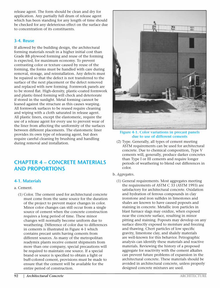
(1) Color. The cement used for architectural concrete must come from the same source for the duration of the project to prevent major changes in color. Minor color changes can still occur from a single source of cement when the concrete construction requires a long period of time. These minor changes will normally become uniform due to weathering. Difference of color due to differences in cements is illustrated in Figure 4-1 which contains precast units having cements from different sources. As many of the metropolitan readymix plants receive cement shipments from more than one company, special precautions will be required to maintain one source. If a special brand or source is specified to obtain a light or buff-colored cement, provisions must be made to ensure that the cement will be available for the entire period of construction.
(2) Type. Generally, all types of cement meeting ASTM requirements can be used for architectural concrete. Due to chemical composition, Type V cements will, generally, produce darker concretes than Type I or III cements and require longer periods of weathering to blend out differences in color.
b. Aggregates.
(1) General requirements. Most aggregates meeting the requirements of ASTM C 33 (ASTM 1993) are satisfactory for architectural concrete. Oxidation and hydration of ferrous compounds in clay ironstone and iron sulfides in limestones and shales are known to have caused popouts and staining in concrete. Metallic iron particles in blast furnace slags may oxidize, when exposed near the concrete surface, resulting in minor pitting and staining. Popouts may develop on any surface directly exposed to moisture and freezing and thawing. Chert particles of low specific gravity, limestone clay, and shalely materials are well-known for this behavior. Petrographic analysis can identify these materials and reactive materials. Reviewing the history of a proposed aggregate for reactivity with the cement alkalies can prevent future problems of expansion in the architectural concrete. These materials should be avoided in architectural concrete, unless properly designed concrete mixtures are used.
Figure 4-1. Color variations in precast panels due to use of different cements
Chapter 4 Concrete Materials and Proportions
4-1. Materials
a. Cement.
(1) Color. The cement used for architectural con- crete must come from the same source for the duration of the project to prevent major changes in color. Minor color changes can still occur from a single source of cement when the concrete construction requires a long period of time. These minor changes will normally become uniform due to weathering. Difference of color due to differences in cements is illustrated in Figure 4-1 which contains precast units having cements from different sources. As many of the metropolitan ready- mix plants receive cement shipments from more than one company, special precautions will be required to maintain one source. If a special brand or source is specified to obtain a light or buff-colored cement, provisions must be made to ensure that the cement will be available for the entire period of construction.
(2) Type. Generally, all types of cement meeting ASTM requirements can be used for architectural con- crete. Due to chemical composition, Type V cements will, generally, produce darker concretes than Type I or III cements and require longer periods of weathering to blend out differences in color.
b. Aggregates.
(1) General requirements. Most aggregates meeting the requirements of ASTM C 33 (ASTM 1993) are satisfactory for architectural concrete. Oxidation and hydration of ferrous compounds in clay ironstone and iron sulfides in limestones and shales are known to have caused popouts and staining in concrete. Metallic iron particles in blast furnace slags may oxidize, when exposed near the concrete surface, resulting in minor pitting and staining. Popouts may develop on any surface directly exposed to moisture and freezing and thawing. Chert particles of low specific gravity, lime- stone clay, and shalely materials are well-known for this behavior. Petrographic analysis can identify these materials and reactive materials. Reviewing the history
EM 1110-1-2009 31 Oct 97
Figure 4-1. Color variations in precast panels due to use of different cements of a proposed aggregate for reactivity with the cement alkalies can prevent future problems of expansion in the architectural concrete. These materials should be avoided in architectural concrete, unless properly designed concrete mixtures are used.
(2) Architectural requirements. For exposed aggregate architectural concrete, source, color, and shape of the aggregate are additional requirements to be included in the specifications. Viewing distance of exposed aggregate textures may require a larger maximum size in order to be seen. Cubical or rounded aggregate provide the best area coverage and are generally self-cleaning during weathering. Crushed aggregate is more likely to pick up airborne dust and contaminants. As durability of exposed aggregate is more critical, more rigid standards of density and absorption should be considered.
4-1
|ARCHITECTURE Architectural Concrete 93
(2) Architectural requirements. For exposed aggregate architectural concrete, source, color, and shape of the aggregate are additional requirements to be included in the specifications. Viewing distance of exposed aggregate textures may require a larger maximum size in order to be seen. Cubical or rounded aggregate provide the best area coverage and are generally self-cleaning during weathering. Crushed aggregate is more likely to pick up airborne dust and contaminants. As durability of exposed aggregate is more critical, more rigid standards of density and absorption should be considered.
c. Admixtures.
(1) General. Admixtures, other than air-entraining admixtures, require additional testing in the field mockup composed of concrete using all the planned concrete materials, form release agents, and curing process to determine any staining or other deleterious effect to the architectural concrete. Since most of the architectural treatments require high-density forming concretes containing the higher dosages of air entrainment tend to be sticky and result in higher amounts of bugholes due to difficulty of removal by vibration. In mild climates, use of the minimum 3 percent air entrainment for workability will decrease the stickiness and the amount of bugholes. For severe climates, air contents should be specified in accordance with the recommendations of ACI 201.2R-92 (ACI 1992C). Calcium chloride is not recommended, as it may cause discoloration in the concrete or affect the efficiency of any surface retarders. The new superplasticizers have assisted the placement of architectural concrete in steel congested areas. However, their use should be checked with all ingredients when casting the field mockup.
(2) Color. Exposed aggregate architectural concrete color is usually achieved by use of fine or coarse aggregate in various proportions which produce the desired color in the concrete. Architects may desire to achieve a color through use of pigments in the concrete. This may be for as-cast finishes or in conjunction with a subsequent treatment such as sandblasting. The pigments are usually finely ground natural or synthetic mineral oxides. Some may react with compounds used on the forms or to clean the surface. This reaction should be discovered if the field mockup is properly constructed with all proposed materials and methods. Additions more than 5 percent by weight of cement do not increase the intensity of the color and additions more than 10 percent will affect the quality of the concrete. In order to produce better uniformity of color, some manufacturers now produce what is known as a colored admixture. The colored admixture is
a blended mixture of pigment, a mineral filler, and a water-reducing admixture which tends to produce uniform-colored concrete through the usual specified range of slump. Most lamp blacks are not as durable or long-lasting as metal oxides producing a black color, and tend to be incompatible with air-entraining agents. Carbon in lamp-black will attack the foaming agents, causing the collapse of the air bubbles. Therefore, the compatibility of the entraining agents and lampblack should be established by appropriate tests prior to their inclusion in the concrete mixture.
(3) Mineral admixtures. Mineral admixtures include flyash, other pozzolanic materials, limestone flour, and other finely ground fillers. In some cases a locally produced pozzolan has been used as an admixture to the concrete for coloring. As most flyashes tend to darken a concrete, prior trials should be made to determine the effect of flyash on the color of the architectural concrete. Other than color, mineral admixtures should not harm the architectural concrete.
d. Water. Water for architectural concrete cannot contain iron, rust, or other chemicals in sufficient quantity to cause staining in light, white, or colored concretes. The field sample concrete should include water from the concrete production source. If water is used for curing, it must also meet this criterion.
e. Recycled wash water. Due to environmental requirements, metropolitan ready-mix concrete firms may be using recycled wash water. Past experiences indicate that color of the concrete will not be significantly affected when a small amount of recycled wash water is used. If recycled water causes problems with the color of the field sample concrete, its use should be stopped.
4-2. Proportions
a. General. Proportioning of architectural concrete mixtures is similar to structural concrete unless a higher percentage of aggregate is desired in exposed aggregate finishes. Some adjustments may be required to diminish size and quantity of bugholes or substitution of an admixture or cement due to incompatibility with another ingredient or procedure. ACI Committee 303 (ACI 1974) recommends the maximum water-cement ratio to be 0.46 by weight of cement. Concrete with higher water-cement ratios tends to have more surface defects.
b. Gap-grading (cast-in-place). In some instances, cast-in-place architectural concrete specifies an exposed aggregate texture having a preponderance of coarse aggregate, which can only be produced by a concrete mixture described as gap-graded. A

Architectural Concrete ARCHITECTURE|92
release agent. The form should be clean and dry for application. Any partially full drum of release agent which has been standing for any length of time should be checked for any deleterious effect on the surface due to concentration of its constituents.
3-4. Reuse
If allowed by the building design, the architectural forming materials result in a higher initial cost than Grade BB plywood forming and reuse of the forming is expected, for maximum economy. To prevent contrasting color or texture caused by reuse of the forming, the forms must be handled with care during removal, storage, and reinstallation. Any defects must be repaired so that the defect is not transferred to the surface of the next placement or the defect removed and replaced with new forming. Formwork panels are to be stored flat. High-density, plastic-coated formwork and plastic-lined forming will check and deteriorate if stored in the sunlight. Metal forming cannot be leaned against the structure as this causes warping. All formwork surfaces to be reused require cleaning and wiping with a cloth saturated in release agent. All plastic liners, except the elastomeric, require the use of a release agent for every use to prevent wear of the liner from affecting the uniformity of the surfaces between different placements. The elastomeric liner provides its own type of releasing agent, but does require careful cleaning by brushing and handling during removal and installation.
CHAPTER 4 – CONCRETE MATERIALS AND PROPORTIONS
4-1. Materials
a. Cement.
(1) Color. The cement used for architectural concrete must come from the same source for the duration of the project to prevent major changes in color. Minor color changes can still occur from a single source of cement when the concrete construction requires a long period of time. These minor changes will normally become uniform due to weathering. Difference of color due to differences in cements is illustrated in Figure 4-1 which contains precast units having cements from different sources. As many of the metropolitan readymix plants receive cement shipments from more than one company, special precautions will be required to maintain one source. If a special brand or source is specified to obtain a light or buff-colored cement, provisions must be made to ensure that the cement will be available for the entire period of construction.
(2) Type. Generally, all types of cement meeting ASTM requirements can be used for architectural concrete. Due to chemical composition, Type V cements will, generally, produce darker concretes than Type I or III cements and require longer periods of weathering to blend out differences in color.
b. Aggregates.
(1) General requirements. Most aggregates meeting the requirements of ASTM C 33 (ASTM 1993) are satisfactory for architectural concrete. Oxidation and hydration of ferrous compounds in clay ironstone and iron sulfides in limestones and shales are known to have caused popouts and staining in concrete. Metallic iron particles in blast furnace slags may oxidize, when exposed near the concrete surface, resulting in minor pitting and staining. Popouts may develop on any surface directly exposed to moisture and freezing and thawing. Chert particles of low specific gravity, limestone clay, and shalely materials are well-known for this behavior. Petrographic analysis can identify these materials and reactive materials. Reviewing the history of a proposed aggregate for reactivity with the cement alkalies can prevent future problems of expansion in the architectural concrete. These materials should be avoided in architectural concrete, unless properly designed concrete mixtures are used.
Figure 4-1. Color variations in precast panels due to use of different cements
Chapter 4 Concrete Materials and Proportions
4-1. Materials
a. Cement.
(1) Color. The cement used for architectural con- crete must come from the same source for the duration of the project to prevent major changes in color. Minor color changes can still occur from a single source of cement when the concrete construction requires a long period of time. These minor changes will normally become uniform due to weathering. Difference of color due to differences in cements is illustrated in Figure 4-1 which contains precast units having cements from different sources. As many of the metropolitan ready- mix plants receive cement shipments from more than one company, special precautions will be required to maintain one source. If a special brand or source is specified to obtain a light or buff-colored cement, provisions must be made to ensure that the cement will be available for the entire period of construction.
(2) Type. Generally, all types of cement meeting ASTM requirements can be used for architectural con- crete. Due to chemical composition, Type V cements will, generally, produce darker concretes than Type I or III cements and require longer periods of weathering to blend out differences in color.
b. Aggregates.
(1) General requirements. Most aggregates meeting the requirements of ASTM C 33 (ASTM 1993) are satisfactory for architectural concrete. Oxidation and hydration of ferrous compounds in clay ironstone and iron sulfides in limestones and shales are known to have caused popouts and staining in concrete. Metallic iron particles in blast furnace slags may oxidize, when exposed near the concrete surface, resulting in minor pitting and staining. Popouts may develop on any surface directly exposed to moisture and freezing and thawing. Chert particles of low specific gravity, lime- stone clay, and shalely materials are well-known for this behavior. Petrographic analysis can identify these materials and reactive materials. Reviewing the history
EM 1110-1-2009 31 Oct 97
Figure 4-1. Color variations in precast panels due to use of different cements of a proposed aggregate for reactivity with the cement alkalies can prevent future problems of expansion in the architectural concrete. These materials should be avoided in architectural concrete, unless properly designed concrete mixtures are used.
(2) Architectural requirements. For exposed aggregate architectural concrete, source, color, and shape of the aggregate are additional requirements to be included in the specifications. Viewing distance of exposed aggregate textures may require a larger maximum size in order to be seen. Cubical or rounded aggregate provide the best area coverage and are generally self-cleaning during weathering. Crushed aggregate is more likely to pick up airborne dust and contaminants. As durability of exposed aggregate is more critical, more rigid standards of density and absorption should be considered.
4-1
|ARCHITECTURE Architectural Concrete 93
(2) Architectural requirements. For exposed aggregate architectural concrete, source, color, and shape of the aggregate are additional requirements to be included in the specifications. Viewing distance of exposed aggregate textures may require a larger maximum size in order to be seen. Cubical or rounded aggregate provide the best area coverage and are generally self-cleaning during weathering. Crushed aggregate is more likely to pick up airborne dust and contaminants. As durability of exposed aggregate is more critical, more rigid standards of density and absorption should be considered.
c. Admixtures.
(1) General. Admixtures, other than air-entraining admixtures, require additional testing in the field mockup composed of concrete using all the planned concrete materials, form release agents, and curing process to determine any staining or other deleterious effect to the architectural concrete. Since most of the architectural treatments require high-density forming concretes containing the higher dosages of air entrainment tend to be sticky and result in higher amounts of bugholes due to difficulty of removal by vibration. In mild climates, use of the minimum 3 percent air entrainment for workability will decrease the stickiness and the amount of bugholes. For severe climates, air contents should be specified in accordance with the recommendations of ACI 201.2R-92 (ACI 1992C). Calcium chloride is not recommended, as it may cause discoloration in the concrete or affect the efficiency of any surface retarders. The new superplasticizers have assisted the placement of architectural concrete in steel congested areas. However, their use should be checked with all ingredients when casting the field mockup.
(2) Color. Exposed aggregate architectural concrete color is usually achieved by use of fine or coarse aggregate in various proportions which produce the desired color in the concrete. Architects may desire to achieve a color through use of pigments in the concrete. This may be for as-cast finishes or in conjunction with a subsequent treatment such as sandblasting. The pigments are usually finely ground natural or synthetic mineral oxides. Some may react with compounds used on the forms or to clean the surface. This reaction should be discovered if the field mockup is properly constructed with all proposed materials and methods. Additions more than 5 percent by weight of cement do not increase the intensity of the color and additions more than 10 percent will affect the quality of the concrete. In order to produce better uniformity of color, some manufacturers now produce what is known as a colored admixture. The colored admixture is
a blended mixture of pigment, a mineral filler, and a water-reducing admixture which tends to produce uniform-colored concrete through the usual specified range of slump. Most lamp blacks are not as durable or long-lasting as metal oxides producing a black color, and tend to be incompatible with air-entraining agents. Carbon in lamp-black will attack the foaming agents, causing the collapse of the air bubbles. Therefore, the compatibility of the entraining agents and lampblack should be established by appropriate tests prior to their inclusion in the concrete mixture.
(3) Mineral admixtures. Mineral admixtures include flyash, other pozzolanic materials, limestone flour, and other finely ground fillers. In some cases a locally produced pozzolan has been used as an admixture to the concrete for coloring. As most flyashes tend to darken a concrete, prior trials should be made to determine the effect of flyash on the color of the architectural concrete. Other than color, mineral admixtures should not harm the architectural concrete.
d. Water. Water for architectural concrete cannot contain iron, rust, or other chemicals in sufficient quantity to cause staining in light, white, or colored concretes. The field sample concrete should include water from the concrete production source. If water is used for curing, it must also meet this criterion.
e. Recycled wash water. Due to environmental requirements, metropolitan ready-mix concrete firms may be using recycled wash water. Past experiences indicate that color of the concrete will not be significantly affected when a small amount of recycled wash water is used. If recycled water causes problems with the color of the field sample concrete, its use should be stopped.
4-2. Proportions
a. General. Proportioning of architectural concrete mixtures is similar to structural concrete unless a higher percentage of aggregate is desired in exposed aggregate finishes. Some adjustments may be required to diminish size and quantity of bugholes or substitution of an admixture or cement due to incompatibility with another ingredient or procedure. ACI Committee 303 (ACI 1974) recommends the maximum water-cement ratio to be 0.46 by weight of cement. Concrete with higher water-cement ratios tends to have more surface defects.
b. Gap-grading (cast-in-place). In some instances, cast-in-place architectural concrete specifies an exposed aggregate texture having a preponderance of coarse aggregate, which can only be produced by a concrete mixture described as gap-graded. A

Architectural Concrete ARCHITECTURE|94
typical gap-graded mix consists of only one size coarse aggregate, graded to allow all particles of sand to be able to pass through the voids of the compacted aggregate. Maximum size is still limited by the spacing of the reinforcing steel. Generally, for a 19-mm (3/4-in.) maximum size, the 9.5-mm to 4.75-mm (3/8-in. to No. 4) sieves are omitted. For a 37.5-mm (1-1/2-in.) maximum size, the 19-mm to 4.75-mm(3/4-in. to No. 4) sieves are omitted. The sand (masonry sand) contains only the material passing the 2.36-mm (No. 8) sieve. A recommended ratio of fine to coarse aggregate is 1:2.5 to 1:3 by weight. By volume of the total aggregate, the range of sand varies between 25 percent and 35 percent, depending on whether the aggregate is rounded or crushed. Air entrainment is required for workability Gap-graded mixes can be consolidated easily with internal vibration with the proper proportions Segregation can be prevented by using the lowest slump needed for consolidation and placement.
c. Gap-grading (precast). Precast units usually contain exposed highly decorative and costly imported aggregates. These units will be manufactured with a thin facing mix of the decorative aggregate and white cement and a backup mix of ordinary gray structural concrete. Both mixes are designed for a compressive strength of 41.4 MPA (6,000 psi) at 28 days. The facing mix has a proportion of cement to fine aggregate of at least 1:3 but not more than 1:1 and approximately the same proportion of total aggregate to cement as the backup mix for equal shrinkage and thermal coefficients. The ratio of fine to coarse aggregate ranges from 1:2.5 or 3. Backup mixes are approximately 1:2.5. The coarse aggregates used in facing mixes are generally of one size, such as 12.5 mm by 19.0 mm (1/2 in. by 3/4 in.) or 6.3 mm by 9.5 mm (1/4 in. by 3/8 in.).
d. Slump. Normal slumps for cast-in-place architectural concrete should be 100 mm (4 in.) ± 25 mm (1 in.) unless a superplasticizer is used to produce flow ing concrete. Gap-graded mixtures can vary from 0 to 75 mm (3 in.) dependent on the thickness of the section, amount of reinforcing steel, and the height of the forming. Horizontal precast work can be placed successfully using a 100-mm (4-in.) slump facing mix and a no-slump backup mix to absorb the extra water from the facing mix. In some cases the slump of precast work is dependent on the special needs for manufacture of an exposed aggregate product. In both cast-in-place and precast architectural concrete, best results are achieved if the concrete slump is kept uniform for the entire production of the architectural product.
e. Temperature requirements. With uniform operations and in accordance with recommended practices, the color of architectural concrete will be uniform if placed between temperatures of 18.3° and 29.4° C (65° and 85° F). Above 26.7° C (80° F), decreased
setting times may result in cold joints, visible lift lines, and mottled sandblasted surfaces, unless concrete delivery is carefully planned. Cold weather requires additional strengthening of the forming system to withstand the necessary additional vibration required for architectural concrete and the higher pressure heads caused by slower-setting concrete. Form stripping times must be delayed to prevent damage to the surface which has lower strengths than normal.
CHAPTER 5 – BATCHING AND TRANSPORTING
5-1. General
Due to the use of special materials and the need to achieve uniformity, the batching and transporting of materials and concrete require preliminary planning to prevent intermingling and problems with scheduling. This would also include a provision to ensure sufficient material for the project.
5-2. Batch Plant
a. Material storage. Every architectural concrete project requiring special aggregates, cement, or color should specify that sufficient materials will be available until the architectural portion is completed. If the aggregate is imported, the producer must be capable of supplying sufficient material for the proposed schedule. Stockpiles should be arranged to prevent co-mingling of the special aggregate with other materials in the plant and any segregation. If the aggregate is stockpiled on the ground, some protection is required to prevent contamination with the base soil. Due to a gradual accumulation of fines at the bottom of a stockpile, the bottom 0.3 m (1 ft) of material should not be used in the architectural concrete, as it will change the characteristics of the surface. When the entire required supply of aggregate is stocked initially, blending of all the material will ensure that the final product is uniform in appearance.
(1) Color should be stored in bags as supplied by the manufacturer. The bagged amounts should be sufficient to color a full load of concrete. The concrete supplier should have complete instructions for partial loads from the color supplier.
(2) The concrete supplier should have the facilities to separately store any special architectural cement. If cement is obtained from more than one supplier, insurance is required that the batch plant silo is kept full of the cement brand being used for the architectural concrete to prevent mixing of different brands.
|ARCHITECTURE Architectural Concrete 95
b. Inspection. Inspection is required at a readymix plant during the batching of architectural concrete. A preliminary inspection should be made of the plant stockpiles and batching facilities prior to any placement of the architectural concrete in the field mockup so as to provide a period for revision if required. The inspection should include checks of methods for adding and batching color, checks of any special cements and methods to ensure one brand, and checks of methods to separate any special aggregates. If precast products are to be used, a preliminary inspection of those facilities should also be made. This would include not only the inspection procedure for the ready-mix plant, but also a check of what quality control procedures are being used for acceptance prior to shipment and storage of completed products.
5-3. Mixing
a. Types. Many types of mixers can be used for mixing of architectural concrete. The most common is the transit mixer. Precast plants will generally use transit mixers or a stationary horizontal pan type of mixer. A tilt drum mixer has difficulty providing uniform color concrete unless transit mixers are used to transport and provide additional mixing. The resulting product from any mixer should be uniform from batch to batch and capable of being discharged from the mixer.
b. Time. Generally, mixing can be considered complete when all ingredients are thoroughly distributed and have a uniform appearance. Time of mixing should be controlled from one batch to another in order to maintain uniformity of color for both precast and castin- place concrete. Cleanness of the mixer is necessary to prevent contamination from oil, grease, dirt, or broken concrete from the inside of the mixer drum or blades. Streaks of material in the mix are an indication of insufficient mixing.
5-4. Scheduling of Trucks
An important part of preplanning is scheduling of concrete delivery to prevent delays or too many trucks. Waiting trucks cause lack of uniformity in the concrete.Delayed arrivals may cause cold joints. Poor scheduling of trucks creates nonuniform mixing times, which often cause nonuniformity in the architectural concrete.
5-5. Contamination
a. General. Contamination of the architectural concrete, by other cements, concretes or materials requires continuous batch plant and job site inspection. As most ready-mix plants are also producing concrete for other projects or other portions of the same project, constant vigilance is required to prevent other concrete from contaminating the architectural concrete. This requires separate batching, transporting, and placing equipment. A good specification is to require that architectural concrete be placed first while all equipment is clean or to use separate equipment.
b. Color uniformity wet check. The use of a pump or transit mix truck immediately after handling gray concrete without thorough cleaning will cause contamination. White or light cements are highly vulnerable to this problem. One should also ensure against delivery of the wrong concrete to the forms by use of the wet patch test on each load of colored concrete. Dry blended material is supplied to the job inspector by the color manufacturer. After minor training, the inspector conducts the test on each concrete load by mixing a capful of the material with a certain amount of water. The result is compared to the first load to check color uniformity. Following loads are compared to the first. The test is sensitive to contamination and inadvertent batching errors. Figure 5-1 illustrates the effect of contamination of architectural concrete containing a light buff-colored cement with a normal gray cement.
Figure 5-1. Illustration of contamination of light architectural cement with regular gray cement (uncontaminated field mockup on left)
EM 1110-1-200931 Oct 97
5-2
Delayed arrivals may cause cold joints. Poor schedul- concrete without thorough cleaning will causeing of trucks creates nonuniform mixing times, which contamination. White or light cements are highlyoften cause nonuniformity in the architectural concrete. vulnerable to this problem. One should also ensure
5-5. Contamination
a. General. Contamination of the architecturalconcrete, by other cements, concretes or materialsrequires continuous batch plant and job site inspection.As most ready-mix plants are also producing concretefor other projects or other portions of the same project,constant vigilance is required to prevent other concretefrom contaminating the architectural concrete. Thisrequires separate batching, transporting, and placingequipment. A good specification is to require that archi-tectural concrete be placed first while all equipment isclean or to use separate equipment.
b. Color uniformity wet check. The use of a pumpor transit mix truck immediately after handling gray
against delivery of the wrong concrete to the forms byuse of the wet patch test on each load of coloredconcrete. Dry blended material is supplied to the jobinspector by the color manufacturer. After minortraining, the inspector conducts the test on eachconcrete load by mixing a capful of the material with acertain amount of water. The result is compared to thefirst load to check color uniformity. Following loadsare compared to the first. The test is sensitive to con-tamination and inadvertent batching errors. Figure 5-1illustrates the effect of contamination of architecturalconcrete containing a light buff-colored cement with anormal gray cement.
Figure 5-1. Illustration of contamination of light architectural cement withregular gray cement (uncontaminated field mockup on left)
Architectural Concrete ARCHITECTURE|96
CHAPTER 6 – CONCRETE PLACEMENT
6-1. General
Architectural concrete may be placed by many methods, including face-down for precast work, face-up for both precast and cast-in-place, and the vertical cast-in-place. Equipment for placement consists of a bucket, buggy, chute, belt, and pump. Each requires changes in procedures and precautions for uniform satisfactory results. All equipment should be clean prior to handling architectural concrete. All concrete requires consolidation to properly compact the mortar around any aggregate to be exposed and to prevent rock pockets and diminish surface bugholes. Placement procedures should be kept uniform for uniform results. The proposed method and equipment should be used on the field mockup sample.
6-2. Effect of Equipment Type
a. Bucket. Placement by bucket will tend to be slower than other methods due to the time required to lift and convey the concrete to the point of delivery and the limited amount of concrete for each delivery. If drop chutes are used, additional time will be required. Production of placed concrete is limited and cold joints can occur with high long forms. Generally, this method is becoming rare for architectural concrete except for those mixtures which cannot be handled by pumping.
b. Pumps. Pumping is becoming the most prevalent method of placing concrete. Its advantages for architectural concrete are the ease of placement in difficult-to-reach areas and the ability of placing concrete in the bottom of a form wide enough to receive the hose. The production rate of 38.2-53.5 m3 (50-70 yd3) per hour can efficiently supply concrete so that cold joints are not a problem as long as equipment or delivery schedule problems do not occur. Pumping of concrete may require changes in proportions of concrete mixtures. This should be limited to a 2- to 3-percent increase in sand and a similar decrease in percentage of coarse aggregate. Such changes should not be initiated after commencing the placement of concrete for exposed aggregate concrete, as uniformity of the surfaces will be affected. If the approved job-site mockup had a different concrete mixture, the approved change in concrete proportions should be followed by construction of a new job-site mockup prior to production use of the new concrete mixture.
c. Belt conveyors. Belting is rarely used for conveying architectural concrete. On elevated structures, such belting conveys the concrete to a hopper for reconsolidation. Due to restricted space for
additional belts, buggies are used to convey the concrete to the vertical forming. For architectural concrete flatwork on grade, belt conveyors may be used economically.
d. Chute. For flatwork and low walls, the chuting of concrete from the ready-mix truck remains the most feasible. If the aggregate has been preplaced, care must be exercised to prevent displacement of the aggregate by the chuted concrete. A slow flow, a low drop, and deflection by a hand shovel is the best method to prevent this. Where Styrofoam or ABS forming is used workmen should be cautioned not to damage the forming by walking within the formed area.
6-3. Placement
a. Form protection. Splattering of mortar on the form must be prevented from occurring as this creates lenses of hardened mortar on the surfaces which are exposed and difficult or impossible to remove during sandblasting. During hot weather, this splatter tends to harden quickly and does not recombine with the concrete reaching that level at a later time. Prevention has included thin metal or polyethylene sheets against the form face which are pulled up as the concrete level rises.
b. Height of layers. Most specifications require layers to be held to heights less than 0.6 m (24 in.). However, greater layer heights up to 1.2 m (4 ft) may not be a problem when concrete is properly consolidated, except under the following conditions:
(1) Gap-graded aggregate mixtures are placed.
(2) Mixtures containing high percentages of coarse aggregate in combination with low slumps are placed.
In both of these cases, the layers must be kept thin. If excessive bugholes are problems, greater layer heights with adequate consolidation may diminish this problem. When superplasticizers are used to develop flowing concrete, layers of 2 m (6-1/2 ft) have been used successfully for architectural concrete. Any proposed placing procedure should be tried out on field mockup samples or a wall which is not architectural or will not be left exposed in the complete building.
c. Timing. Timing of the placement depends on scheduling of the concrete, temperature of the concrete, and the method of placement. If problems are occurring, some changes in procedure must be made. Any change should be tried in some unimportant area to determine any change in the architectural appearance. Uniform placement procedures are key to a uniform product.
|ARCHITECTURE Architectural Concrete 97
6-4. Consolidation
The technology of consolidation can be found in the standards produced by ACI Committee 309 (ACI 1990a, 1992b, 1993, 1996). Additional requirements for architectural concrete are listed below.
a. Internal vibration. The main goals of internal vibration are to thoroughly consolidate the mortar around the reinforcing steel and aggregate and to force the face air bubbles upward toward the surface. Consolidation techniques are described in Engineer Manual 1110-2-2000. Time for vibration can be determined on the field mockup when the proposed mix is placed. For thick sections, consideration must be given to using high-amplitude and high-frequency vibrators in tandem. In no case should the vibrators be used any closer to the form face than 50 mm (2 in.) for as-cast finishes and 75 mm (3 in.) for exposed aggregate finishes. For harsh mixes, the vibration should cease when the mortar just covers the rock to prevent a dark lense upon exposure. The rock has a tendency to lock up after vibration and it may be difficult to penetrate from the next lift. Generally, internal vibration is not used for precast flatwork except around hardware to be encased in concrete.
b. External vibration. External vibration is used by most precast plants for consolidation of architectural flatwork. The equipment is usually air operated and attached to metal framing supporting the concrete formwork. Formwork must be reinforced for the external forces. This vibration has been found to be beneficial for removal of surface air voids. Care must be exercised with rib type ABS liners used on vertical forming, as the form pressures may be too high and collapse the ribs.
c. Revibration. A second delayed vibration after most of the bleeding has taken place, but before initial set has begun, will help to further densify the concrete and remove additional bugholes from the face of the concrete. Revibration of the top lift will prevent the darkening of the last lift and lessen the large amount of air bugholes normally found there. Sufficient concrete should be available for releveling of the top after revibration. Revibration can be beneficial as long as the vibrator still penetrates by its own weight.
CHAPTER 7 – CURING AND FORM REMOVAL
7-1. Types of Curing
Consistency in length and type of curing will result in uniform color of concrete. Any proposed method should be used on the field mockup sample to determine its effect on architectural appearance.
General recommendations are given in ACI Committee (ACI 1992d). The most common type of cure is leaving the form on for a certain period of time and, concurrently, keeping the form moist. Timing may vary from 3 to 7 days dependent on the weather and whether a follow-up method is to be applied after form removal. When a high-density forming system is used, the initial blotchiness of the surface will be lighter with earlier form removals. Figure 7-1 illustrates a discolored concrete surface, due to trapped moisture, after removal of high-density forming. Figure 7-2 illustrates the gradual disappearance of the discoloration by drying of the surface. When polyethylene is used for further curing, some means must be provided to keep it off the surface of the concrete to prevent mottling. Membrane curing seals may be applied when further treatment such as sandblasting or bush hammering is to be done. In all other cases the membrane may interfere with the application of sealers or sealants. A water cure or covering should not be used on colored flatwork as color uniformity may be affected. The best cure is a clear membrane. Precast plants use steam, warm temperatures, or moist curing.
7-2. Hot and Cold Weather
a. General. Extremes of hot and cold weather can become hazardous to the manufacture of architectural concrete unless precautions are taken.
b. Hot weather. During hot weather, scheduling of concrete trucks must be closely monitored to ensure that the arrivals do not overtax the placing forces and result in waiting periods and long mixing times. Adding water to the mixer to make it workable should not be allowed under any circumstance. Long mixing produces heat and more fines, and results in more shrinkage and subsequent cracking. A surface to be sandblasted cannot have cracking. Large temperature differentials between placements may affect the uniformity of the color. Curing during hot weather requires early application to ensure that early strengths will resist cracking due to volume change. By using burlap and blankets for water curing, large temperature changes are avoided in the concrete.
c. Cold weather. Cold weather requires maintenance of the concrete temperature at 10o C (50o F) for the prescribed number of days for strength gain. Any heated precast or cast-in-place exposed surface should not be cooled more than 4.4o C (40o F) per day to prevent crazing. Extremely cold water used for curing may also cause crazing in warm concrete due to thermal shock.
7-3. Form Removal
a. Precast concrete. Form removal for precast plants is dictated by the selected period of hardening.
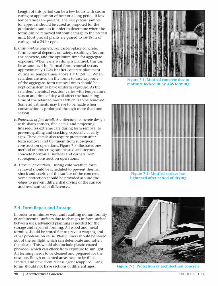
Architectural Concrete ARCHITECTURE|98
EM 1110-1-2009 31 Oct 97
Figure 7-1. Mottled concrete due to moisture locked in by ABS forming
Figure 7-2. Mottled surface has lightened after period of drying
projecting fins requires extreme care during form construction operations. Figure 7-3 illustrates one removal to prevent spalling and cracking, especially at method of protecting sandblasted architectural concrete early ages. These details also require protection after horizontal surfaces and corners from subsequent form removal and treatment from subsequent construction operations.
7-2
Figure 7-1. Mottled concrete due to moisture locked in by ABS forming
Length of this period can be a few hours with steam curing or application of heat or a long period if low temperatures are present. The first precast sample for approval should be cured as proposed for the production samples in order to determine when the forms can be removed without damage to the precast unit. Most precast plants are geared to 16-18 hr of curing and a 24-hr cycle.
b. Cast-in-place concrete. For cast-in-place concrete, form removal depends on safety, resulting effect on the concrete, and the optimum time for aggregate exposure. When early washing is planned, this can be as soon as 4 hr. Normal form removal occurs approximately 12-24 hr after concrete placement during air temperatures above 10o C (50o F). When retarders are used on the forms to ease exposure of the aggregate, form removal times should be kept consistent to have uniform exposure. As the retarders’ chemical reaction varies with temperature, season and time of day will affect the hardening time of the retarded mortar which is to be removed. Some adjustments may have to be made when construction is prolonged through more than one season.
c. Protection of fine detail. Architectural concrete design with sharp corners, fine detail, and projecting fins requires extreme care during form removal to prevent spalling and cracking, especially at early ages. These details also require protection after form removal and treatment from subsequent construction operations. Figure 7-3 illustrates one method of protecting sandblasted architectural concrete horizontal surfaces and corners from subsequent construction operations.
d. Thermal precautions. During cold weather, form removal should be scheduled to prevent thermal shock and crazing of the surface of the concrete. Some protection should be provided around the edges to prevent differential drying of the surface and resultant color differences.
7-4. Form Repair and Storage
In order to minimize wear and resulting nonuniformity of architectural surfaces due to changes in form surface between uses, advanced planning is needed for the storage and repair of forming. All wood and metal forming should be stored flat to prevent warping and other problems on reuse. Plastic liners should be stored out of the sunlight which can deteriorate and soften the plastic. This would also include plastic-coated plywood, which can check from exposure to sunlight. All forming needs to be cleaned and prepared for the next use. Rough or dented areas need to be filled, sanded, and have form release agent reapplied. Gang forms should not have sections of different ages.
EM 1110-1-2009 31 Oct 97
Figure 7-1. Mottled concrete due to moisture locked in by ABS forming
Figure 7-2. Mottled surface has lightened after period of drying
projecting fins requires extreme care during form construction operations. Figure 7-3 illustrates one removal to prevent spalling and cracking, especially at method of protecting sandblasted architectural concrete early ages. These details also require protection after horizontal surfaces and corners from subsequent form removal and treatment from subsequent construction operations.
7-2
Figure 7-2. Mottled surface has lightened after period of drying
Figure 7-3. Protection of architectural concrete
EM 1110-1-2009 31 Oct 97
d. Thermal precautions. During cold weather, between uses, advanced planning is needed for the stor-
form removal should be scheduled to prevent thermal age and repair of forming. All wood and metal forming shock and crazing of the surface of the concrete. Some should be stored flat to prevent warping and other prob- protection should be provided around the edges to pre- lems on reuse. Plastic liners should be stored out of the vent differential drying of the surface and resultant color sunlight which can deteriorate and soften the plastic. differences. This would also include plastic-coated plywood, which
can check from exposure to sunlight. All forming needs 7-4. Form Repair and Storage In order to minimize wear and resulting nonuniformity of architectural surfaces due to changes in form surface
to be cleaned and prepared for the next use. Rough or dented areas need to be filled, sanded, and have form release agent reapplied. Gang forms should not have sections of different ages.
7-3
Figure 7-3. Protection of architectural concrete
|ARCHITECTURE Architectural Concrete 99
CHAPTER 8 – EXPOSED AGGREGATE ARCHITECTURAL SURFACES
8-1. Aggregate Distribution Methods
a. Mixture proportions. This aggregate distribution method depends on random dispersion of aggregate at the surface of concrete placed either horizontally or vertically into forms. The quantity of coarse aggregate exposed is determined by the proportioning of the concrete mixture. This can vary from the ordinary paving or structural mixture to one designed with a gap-grading and a preponderance of coarse aggregate.
b. Aggregate transfer. The aggregate transfer method of distribution is rarely used due to labor costs, but remains the best means of producing distinctive patterns and sculptured effects with special aggregates. The pattern is laid out on a thin 6.3-mm (1/4-in.) plywood panel and adhesive is applied. This is followed by a layer of aggregate arranged in the desired pattern and entirely covering the liner panel. Some vibration is provided in the horizontal direction. The panel is fastened to the forms with finish nails after the adhesive has hardened. Removal occurs when the concrete is a minimum of 5 days old, dependent on curing temperatures. Use of an adhesive mix containing 50 percent perlite will allow greater reveals. Final cleaning of the aggregates is needed.
c. Preplaced aggregate. The preplaced aggregate method of distribution has aggregate prepositioned in the forms. The voids are then filled with a structural quality grout by high-frequency vibration or pressure. The advantage of this method is a resulting uniform density of exposed aggregate upon completion. These projects usually contain one size of large aggregate particles and are limited to a minimum 254- to 305-mm (10- to 12-in.)-thick section. Exposure of the aggregate is similar to other methods.
d. Aggregate seeding. The aggregate seeding method of distribution is used for placing aggregate in precast and cast-in-place flatwork. The process involves leaving a level surface of concrete 3.2 mm to 11.1 mm (1/8 in. to 7/16 in.) below the finish elevation to allow for the volume of aggregate to be seeded. This depth is approximately one third the depth of the aggregate size. The aggregate is spread carefully by shovel or hand so as to completely cover the surface. Embedment with a wood float, 2 by 4, or roller continues until the aggregate is well tamped into the plastic concrete. Final tamping with a magnesium type of float continues until the aggregate is completely surrounded and covered by the mortar. Upon completion of the tamping, the slab has the look of a normal slab. A surface
retarder may be used for large areas to allow time for seeding small size aggregate. When the mortar has set sufficiently to hold the aggregate, the aggregate is exposed by washing and brushing with water.
e. Sand embedment. To achieve a uniform distribution on the bottom of a precast panel which requires an exposed aggregate finish on both sides, a process similar to seeding, known as sand embedment, is used. This involves placing a layer of fine sand in the bottom of the form to a depth of one third the maximum size of the aggregate to be exposed. The aggregate is spread similar to seeding and pressed into the sand. A fine spray of water is used to consolidate the sand and leave one half to two thirds of each aggregate particle exposed. Another method is to place the aggregate in the bottom of the form and then sift the sand over the aggregate until each particle is covered one half to one third of its diameter. Any excess sand is pushed down around the rock with a soft bristled brush and compressed air. Again, a fine spray of water is used to consolidate the sand around the aggregate. Placement of concrete must not displace the sand or aggregate. After form removal, the sand is cleaned off with compressed air, water spray, and brushing. In some cases, a retarder in the sand has been successful in easing this removal. As some of the sand may adhere, its color should be similar to the decorative aggregate.
8-2. Aggregate Exposure Methods
a. Water brush. Exposure of aggregate by water brushing is the general method of exposing aggregate in precast and cast-in-place flatwork. This method does not cause a change in the aggregate original color and texture as it involves the mechanical removal of the mortar by brushing with the assistance of water to soften and dilute the surface mortar. Exposure of the aggregate should not begin until the concrete mortar matrix is sufficiently hard enough to retain the aggregate but still soft enough for removal. Forming for cast-in-place vertical surfaces should be removed within 4 hr, dependent on hydration temperatures, to allow exposure by water brushing. Surface retarders will allow more leeway in form removals, but require strict supervision to ensure uniformity. When early form removal cannot be accomplished, aggregate on vertical surfaces can be exposed by sandblasting. Residual mortar from water brushing may be cleaned off with a mild muriatic acid wash.
b. Surface retarders. In order to ease the exposure of decorative aggregate in architectural concrete, retarders are used to delay the hardening of the surface mortar on horizontal and vertical surfaces.
(1) Horizontal surfaces. On precast or cast-in-place flatwork, exposure time is extended to allow
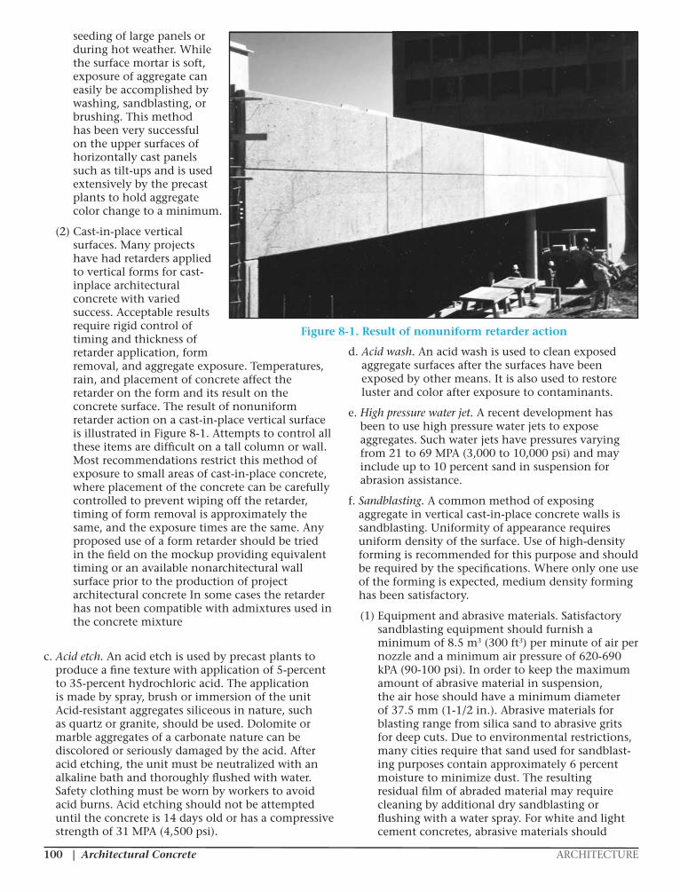
Architectural Concrete ARCHITECTURE|100
seeding of large panels or during hot weather. While the surface mortar is soft, exposure of aggregate can easily be accomplished by washing, sandblasting, or brushing. This method has been very successful on the upper surfaces of horizontally cast panels such as tilt-ups and is used extensively by the precast plants to hold aggregate color change to a minimum.
(2) Cast-in-place vertical surfaces. Many projects have had retarders applied to vertical forms for cast-inplace architectural concrete with varied success. Acceptable results require rigid control of timing and thickness of retarder application, form removal, and aggregate exposure. Temperatures, rain, and placement of concrete affect the retarder on the form and its result on the concrete surface. The result of nonuniform retarder action on a cast-in-place vertical surface is illustrated in Figure 8-1. Attempts to control all these items are difficult on a tall column or wall. Most recommendations restrict this method of exposure to small areas of cast-in-place concrete, where placement of the concrete can be carefully controlled to prevent wiping off the retarder, timing of form removal is approximately the same, and the exposure times are the same. Any proposed use of a form retarder should be tried in the field on the mockup providing equivalent timing or an available nonarchitectural wall surface prior to the production of project architectural concrete In some cases the retarder has not been compatible with admixtures used in the concrete mixture
c. Acid etch. An acid etch is used by precast plants to produce a fine texture with application of 5-percent to 35-percent hydrochloric acid. The application is made by spray, brush or immersion of the unit Acid-resistant aggregates siliceous in nature, such as quartz or granite, should be used. Dolomite or marble aggregates of a carbonate nature can be discolored or seriously damaged by the acid. After acid etching, the unit must be neutralized with an alkaline bath and thoroughly flushed with water. Safety clothing must be worn by workers to avoid acid burns. Acid etching should not be attempted until the concrete is 14 days old or has a compressive strength of 31 MPA (4,500 psi).
d. Acid wash. An acid wash is used to clean exposed aggregate surfaces after the surfaces have been exposed by other means. It is also used to restore luster and color after exposure to contaminants.
e. High pressure water jet. A recent development has been to use high pressure water jets to expose aggregates. Such water jets have pressures varying from 21 to 69 MPA (3,000 to 10,000 psi) and may include up to 10 percent sand in suspension for abrasion assistance.
f. Sandblasting. A common method of exposing aggregate in vertical cast-in-place concrete walls is sandblasting. Uniformity of appearance requires uniform density of the surface. Use of high-density forming is recommended for this purpose and should be required by the specifications. Where only one use of the forming is expected, medium density forming has been satisfactory.
(1) Equipment and abrasive materials. Satisfactory sandblasting equipment should furnish a minimum of 8.5 m3 (300 ft3) per minute of air per nozzle and a minimum air pressure of 620-690 kPA (90-100 psi). In order to keep the maximum amount of abrasive material in suspension, the air hose should have a minimum diameter of 37.5 mm (1-1/2 in.). Abrasive materials for blasting range from silica sand to abrasive grits for deep cuts. Due to environmental restrictions, many cities require that sand used for sandblast-ing purposes contain approximately 6 percent moisture to minimize dust. The resulting residual film of abraded material may require cleaning by additional dry sandblasting or flushing with a water spray. For white and light cement concretes, abrasive materials should
EM 1110-1-200931 Oct 97
8-3
Figure 8-1. Result of nonuniform retarder action
white and light cement concretes, abrasive materials (c) Medium. Maximum reveal 6.4 mm (1/4 in.).should be checked for color contamination. Blasting Exposure of coarse aggregate expected to predominate.should be done with the nozzle perpendicular to thesurface and about 0.6 m (2 ft) away. The actual (d) Heavy. Maximum reveal 12.7 mm (1/2 in.) ordistance will depend on air pressure, hardness of the 1/3 diameter of coarse aggregate. Surface to be mostlyconcrete, and the cutting rate of the abrasive. rock.
(2) Grades. ACI Committee Report 303 (ACI Proper time of sandblasting varies with the grade1974) developed four grades of sandblasting for use by specified, economics, and the construction schedule.the concrete construction industry which should be used Concrete strengths should be above 13.8 MPAfor planning, design, and construction. The grades are (2,000 psi). Brush and light sandblasting can be done atbased on amount of reveal, which is defined as the the convenience of the construction schedule, except thatamount of projection of the aggregate out of the all sandblasting should be done at the same age. A cau-concrete matrix. Visual examples of the four grades tion is given that brush and light grades requirecan be seen in Figures 8-2, 8-3, and 8-4. The grades excellent concrete as they accentuate any defects suchare defined as: as bugholes, lift lines, form leakage areas, cracks, and
(a) Brush. No reveal is expected. Purpose is to medium and heavy, the randomness of the rock size,remove sheen due to high-density forming. May not be distribution, and color begin to dominate the overallsufficient to produce uniform color. appearance and the contrast of any deficiencies
(b) Light. Maximum reveal 1.6 mm (1/16 in.). results on the aggregate if sandblasting is begun withinExposure of occasional coarse aggregate acceptable but 24 to 72 hr after placement for the medium and heavynot mandatory. Resulting color expected to be uniform. grades. As the concrete ages, the matrix abrasion
rock pockets. As the depth of sandblasting increases to
diminishes. It is more economical and less abrasion
Figure 8-1. Result of nonuniform retarder action
|ARCHITECTURE Architectural Concrete 101
be checked for color contamination. Blasting should be done with the nozzle perpendicular to the surface and about 0.6 m (2 ft) away. The actual distance will depend on air pressure, hardness of the concrete, and the cutting rate of the abrasive.
(2) Grades. ACI Committee Report 303 (ACI 1974) developed four grades of sandblasting for use by the concrete construction industry which should be used for planning, design, and construction. The grades are based on amount of reveal, which is defined as the amount of projection of the aggregate out of the concrete matrix. Visual examples of the four grades can be seen in Figures 8-2, 8-3, and 8-4. The grades are defined as:
(a) Brush. No reveal is expected. Purpose is to remove sheen due to high-density forming. May not be sufficient to produce uniform color.
(b) Light. Maximum reveal 1.6 mm (1/16 in.). Exposure of occasional coarse aggregate acceptable but not mandatory. Resulting color expected to be uniform.
(c) Medium. Maximum reveal 6.4 mm (1/4 in.). Exposure of coarse aggregate expected to predominate.
(d) Heavy. Maximum reveal 12.7 mm (1/2 in.) or 1/3 diameter of coarse aggregate. Surface to be mostly rock.
Proper time of sandblasting varies with the grade specified, economics, and the construction schedule. Concrete strengths should be above 13.8 MPA (2,000 psi). Brush and light sandblasting can be done at the convenience of the construction schedule, except that all sandblasting should be done at the same age. A caution is given that brush and light grades require excellent concrete as they accentuate any defects such
as bugholes, lift lines, form leakage areas, cracks, and rock pockets. As the depth of sandblasting increases to medium and heavy, the randomness of the rock size, distribution, and color begin to dominate the overall appearance and the contrast of any deficiencies diminishes. It is more economical and less abrasion results on the aggregate if sandblasting is begun within 24 to 72 hr after placement for the medium and heavy grades. As the concrete ages, the matrix abrasion resistance begins to approach or exceed that of the aggregate. In order to achieve the same reveal, lightening and flattening of the aggregate are
EM 1110-1-200931 Oct 97
8-4
Figure 8-2. Examples of sandblasting grades: brush on left and light on right
Figure 8-3. Light sandblast on left, medium sandblast on right
resistance begins to approach or exceed that of the lighter than the original color. Prior to any sandblastingaggregate. In order to achieve the same reveal, operations, proposed methods and materials should belightening and flattening of the aggregate are increased. tried on the field mockup to determine if the completedAll aggregates exposed by sandblasting will tend to be product meets the architectural and cover requirements.
Figure 8-2. Examples of sandblasting grades: brush on left and light on right
Figure 8-3. Light sandblast on left, medium sandblast on right
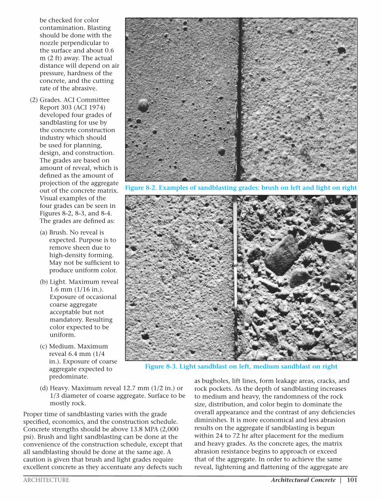
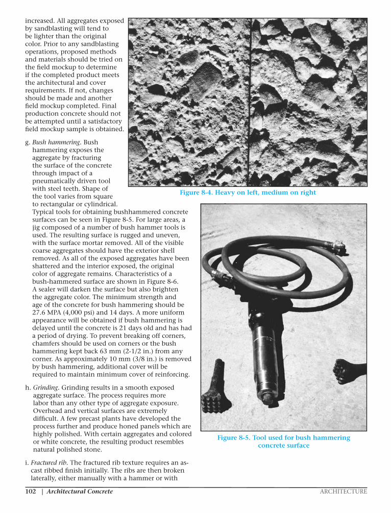
Architectural Concrete ARCHITECTURE|102
increased. All aggregates exposed by sandblasting will tend to be lighter than the original color. Prior to any sandblasting operations, proposed methods and materials should be tried on the field mockup to determine if the completed product meets the architectural and cover requirements. If not, changes should be made and another field mockup completed. Final production concrete should not be attempted until a satisfactory field mockup sample is obtained.
g. Bush hammering. Bush hammering exposes the aggregate by fracturing the surface of the concrete through impact of a pneumatically driven tool with steel teeth. Shape of the tool varies from square to rectangular or cylindrical. Typical tools for obtaining bushhammered concrete surfaces can be seen in Figure 8-5. For large areas, a jig composed of a number of bush hammer tools is used. The resulting surface is rugged and uneven, with the surface mortar removed. All of the visible coarse aggregates should have the exterior shell removed. As all of the exposed aggregates have been shattered and the interior exposed, the original color of aggregate remains. Characteristics of a bush-hammered surface are shown in Figure 8-6. A sealer will darken the surface but also brighten the aggregate color. The minimum strength and age of the concrete for bush hammering should be 27.6 MPA (4,000 psi) and 14 days. A more uniform appearance will be obtained if bush hammering is delayed until the concrete is 21 days old and has had a period of drying. To prevent breaking off corners, chamfers should be used on corners or the bush hammering kept back 63 mm (2-1/2 in.) from any corner. As approximately 10 mm (3/8 in.) is removed by bush hammering, additional cover will be required to maintain minimum cover of reinforcing.
h. Grinding. Grinding results in a smooth exposed aggregate surface. The process requires more labor than any other type of aggregate exposure. Overhead and vertical surfaces are extremely difficult. A few precast plants have developed the process further and produce honed panels which are highly polished. With certain aggregates and colored or white concrete, the resulting product resembles natural polished stone.
i. Fractured rib. The fractured rib texture requires an as-cast ribbed finish initially. The ribs are then broken laterally, either manually with a hammer or with
EM 1110-1-200931 Oct 97
8-5
Figure 8-4. Heavy on left, medium on right
If not, changes should be made and another field used on corners or the bush hammering kept backmockup completed. Final production concrete should 63 mm (2-1/2 in.) from any corner. As approximatelynot be attempted until a satisfactory field mockup 10 mm (3/8 in.) is removed by bush hammering,sample is obtained. additional cover will be required to maintain minimum
g. Bush hammering. Bush hammering exposes theaggregate by fracturing the surface of the concrete h. Grinding. Grinding results in a smooththrough impact of a pneumatically driven tool with steel exposed aggregate surface. The process requires moreteeth. Shape of the tool varies from square to labor than any other type of aggregate exposure.rectangular or cylindrical. Typical tools for obtaining Overhead and vertical surfaces are extremely difficult.bushhammered concrete surfaces can be seen in Fig- A few precast plants have developed the process furtherure 8-5. For large areas, a jig composed of a number of and produce honed panels which are highly polished.bush hammer tools is used. The resulting surface is With certain aggregates and colored or white concrete,rugged and uneven, with the surface mortar removed. the resulting product resembles natural polished stone.All of the visible coarse aggregates should have theexterior shell removed. As all of the exposed aggregates i. Fractured rib. The fractured rib texturehave been shattered and the interior exposed, the requires an as-cast ribbed finish initially. The ribs areoriginal color of aggregate remains. Characteristics of a then broken laterally, either manually with a hammerbush-hammered surface are shown in Figure 8-6. A orwith a mechanical tool. If the blows are fromsealer will darken the surface but also brighten the alternate directions, the result is a rugged type of textureaggregate color. The minimum strength and age of the with broken aggregate visible in the fractured rib. Trialconcrete for bush hammering should be 27.6 MPA fracturing of ribs should be made to train personnel and(4,000 psi) and 14 days. A more uniform appearance determine proper timing for adequate bond strength towill be obtained if bush hammering is delayed until the ensure fracturing of the aggregate. Figure 8-7 illus-concrete is 21 days old and has had a period of drying. trates the development of a fractured rib texture.To prevent breaking off corners, chamfers should be
cover of reinforcing.
Figure 8-4. Heavy on left, medium on right
EM 1110-1-200931 Oct 97
8-6
Figure 8-5. Tool used for bush hammering concretesurface
Figure 8-5. Tool used for bush hammering concrete surface
|ARCHITECTURE Architectural Concrete 103
a mechanical tool. If the blows are from alternate directions, the result is a rugged type of texture with broken aggregate visible in the fractured rib. Trial fracturing of ribs should be made to train personnel and determine proper timing for adequate bond strength to ensure fracturing of the aggregate. Figure 8-7 illustrates the development of a fractured rib texture.
CHAPTER 9 – REPAIRS AND FINAL FINISHING
9-1. Tolerances
a. Specifications. The specifications should list the proper procedures and timing for repairs which become necessary for the architectural concrete. Trial repairs should be required on the field mockup prior to attempting them on the production of architectural concrete. It should be clear in the
specifications that repair procedures must be approved prior to actual use. Tolerances of an acceptable appearance can be determined by a review of the field mockup.
b. Mockup. Although the main purpose of a field mockup is to determine the effectiveness of the contractor’s proposed materials and procedures to produce the desired architectural appearance, the mockup should also be used to determine whether his methods, materials, and personnel will result in non-contrasting repairs. If the mockup is sized properly to include all of the contractor’s procedures and formwork details, opportunities will be available to test the contractor’s repair methods.
9-2. Finishing Methods
a. As-cast surfaces. Depending on the designer and the specifications, an as-cast surface may be left without any additional work or, to improve uniformity of appearance, sack rubbing may be required. For
EM 1110-1-200931 Oct 97
8-7
Figure 8-6. Bush-hammered surface
Figure 8-7. Fractured rib texture being developed
EM 1110-1-200931 Oct 97
8-7
Figure 8-6. Bush-hammered surface
Figure 8-7. Fractured rib texture being developed
Figure 8-6. Bush-hammered surface
Figure 8-7.Fractured rib texture
being developed
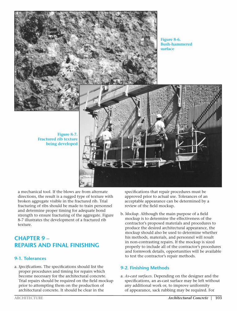
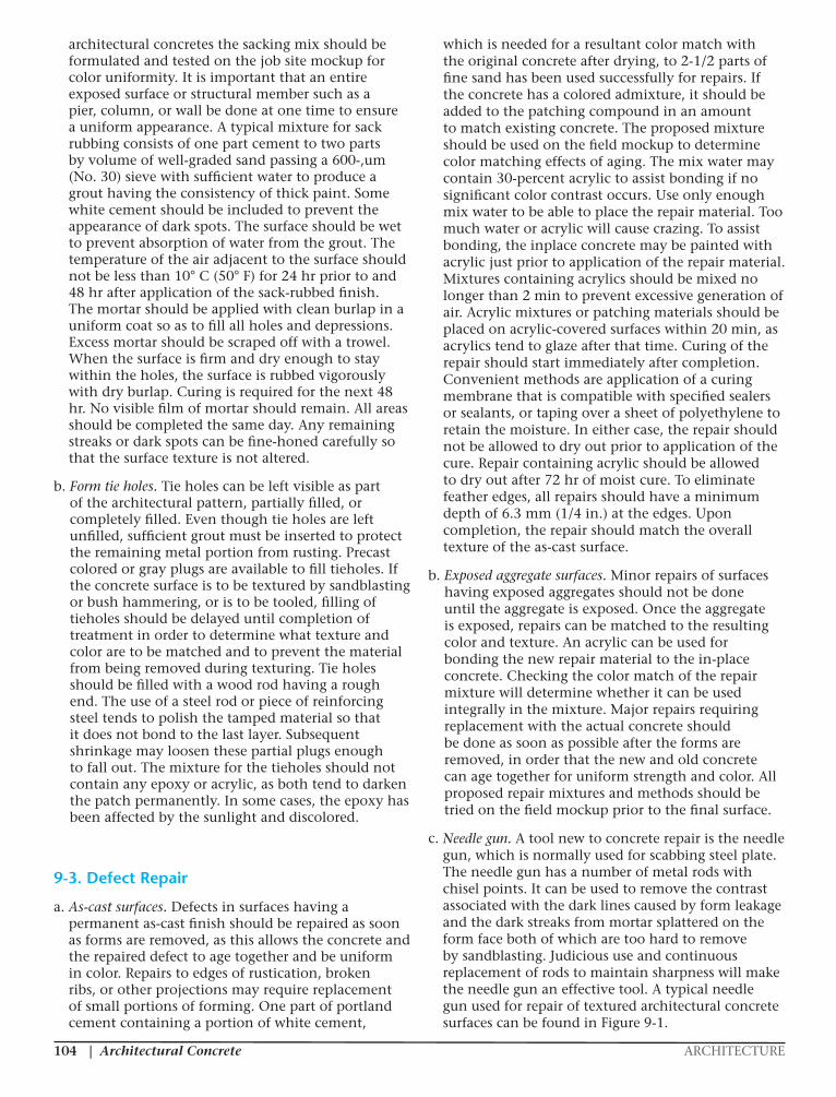
Architectural Concrete ARCHITECTURE|104
architectural concretes the sacking mix should be formulated and tested on the job site mockup for color uniformity. It is important that an entire exposed surface or structural member such as a pier, column, or wall be done at one time to ensure a uniform appearance. A typical mixture for sack rubbing consists of one part cement to two parts by volume of well-graded sand passing a 600-,um (No. 30) sieve with sufficient water to produce a grout having the consistency of thick paint. Some white cement should be included to prevent the appearance of dark spots. The surface should be wet to prevent absorption of water from the grout. The temperature of the air adjacent to the surface should not be less than 10° C (50° F) for 24 hr prior to and 48 hr after application of the sack-rubbed finish. The mortar should be applied with clean burlap in a uniform coat so as to fill all holes and depressions. Excess mortar should be scraped off with a trowel. When the surface is firm and dry enough to stay within the holes, the surface is rubbed vigorously with dry burlap. Curing is required for the next 48 hr. No visible film of mortar should remain. All areas should be completed the same day. Any remaining streaks or dark spots can be fine-honed carefully so that the surface texture is not altered.
b. Form tie holes. Tie holes can be left visible as part of the architectural pattern, partially filled, or completely filled. Even though tie holes are left unfilled, sufficient grout must be inserted to protect the remaining metal portion from rusting. Precast colored or gray plugs are available to fill tieholes. If the concrete surface is to be textured by sandblasting or bush hammering, or is to be tooled, filling of tieholes should be delayed until completion of treatment in order to determine what texture and color are to be matched and to prevent the material from being removed during texturing. Tie holes should be filled with a wood rod having a rough end. The use of a steel rod or piece of reinforcing steel tends to polish the tamped material so that it does not bond to the last layer. Subsequent shrinkage may loosen these partial plugs enough to fall out. The mixture for the tieholes should not contain any epoxy or acrylic, as both tend to darken the patch permanently. In some cases, the epoxy has been affected by the sunlight and discolored.
9-3. Defect Repair
a. As-cast surfaces. Defects in surfaces having a permanent as-cast finish should be repaired as soon as forms are removed, as this allows the concrete and the repaired defect to age together and be uniform in color. Repairs to edges of rustication, broken ribs, or other projections may require replacement of small portions of forming. One part of portland cement containing a portion of white cement,
which is needed for a resultant color match with the original concrete after drying, to 2-1/2 parts of fine sand has been used successfully for repairs. If the concrete has a colored admixture, it should be added to the patching compound in an amount to match existing concrete. The proposed mixture should be used on the field mockup to determine color matching effects of aging. The mix water may contain 30-percent acrylic to assist bonding if no significant color contrast occurs. Use only enough mix water to be able to place the repair material. Too much water or acrylic will cause crazing. To assist bonding, the inplace concrete may be painted with acrylic just prior to application of the repair material. Mixtures containing acrylics should be mixed no longer than 2 min to prevent excessive generation of air. Acrylic mixtures or patching materials should be placed on acrylic-covered surfaces within 20 min, as acrylics tend to glaze after that time. Curing of the repair should start immediately after completion. Convenient methods are application of a curing membrane that is compatible with specified sealers or sealants, or taping over a sheet of polyethylene to retain the moisture. In either case, the repair should not be allowed to dry out prior to application of the cure. Repair containing acrylic should be allowed to dry out after 72 hr of moist cure. To eliminate feather edges, all repairs should have a minimum depth of 6.3 mm (1/4 in.) at the edges. Upon completion, the repair should match the overall texture of the as-cast surface.
b. Exposed aggregate surfaces. Minor repairs of surfaces having exposed aggregates should not be done until the aggregate is exposed. Once the aggregate is exposed, repairs can be matched to the resulting color and texture. An acrylic can be used for bonding the new repair material to the in-place concrete. Checking the color match of the repair mixture will determine whether it can be used integrally in the mixture. Major repairs requiring replacement with the actual concrete should be done as soon as possible after the forms are removed, in order that the new and old concrete can age together for uniform strength and color. All proposed repair mixtures and methods should be tried on the field mockup prior to the final surface.
c. Needle gun. A tool new to concrete repair is the needle gun, which is normally used for scabbing steel plate. The needle gun has a number of metal rods with chisel points. It can be used to remove the contrast associated with the dark lines caused by form leakage and the dark streaks from mortar splattered on the form face both of which are too hard to remove by sandblasting. Judicious use and continuous replacement of rods to maintain sharpness will make the needle gun an effective tool. A typical needle gun used for repair of textured architectural concrete surfaces can be found in Figure 9-1.
|ARCHITECTURE Architectural Concrete 105
9-4. Stain Removal
Stains are difficult to remove from concrete without some effect on the surface texture, as some of the material has usually been absorbed into the concrete. Prevention is the best possible insurance. Care not to allow iron or steel to rest against or on completed concrete will prevent rust staining. Once present, a rust stain may be removed by soaking for 10 min, accompanied by brushing periodically, with a solution containing 30 ml (1 oz) of sodium citrate per 180 ml (6 oz) of water. This is followed by applying crystals of sodium hyposulfite and covering the area with a paste of fuller’s earth and water. The material is removed after drying for 10 min and flushing the area well with clean water. The process may have to be repeated. For many of the stains caused by other materials such as food, there are commercial cleansers. Efflorescence and calcium carbonate deposits may be removed from the concrete with mild solutions of muriatic acid. The surface should be thoroughly flushed with water to remove the acid, as delayed or incomplete removal may etch the concrete. It is difficult to use acid on vertical surfaces due to nonuniform application and running. A last resort is to use a light sandblast if the resulting texture can be accepted. A trial on an area not visible to the public will provide an example for determination. Generally, sandblasting cannot be limited to a small area, as the difference in texture will contrast.
9-5. Protective Coatings
a. Clear coatings. Generally, clear coatings are not necessary unless used to protect a textured surface against weathering and freeze-thaw in severe or
ocean climates, graffiti, staining from spillage in eating areas, or to prevent color changes due to airborne pollutants. Many coatings are proprietary and should be tested on the field mockup for yellowing, chalking, and effect on concrete color and texture. Generically, they include silicones, acrylics, acrylic methacrylates, urethanes, polyurethanes, and epoxies. Silicones have a life of 1-3 years and an affinity for hydrocarbon contaminants. The acrylics and methacrylates have had good success and last over 10 years. The heavier-bodied type of sealers dry to a glossy finish which will dull with time. The urethanes, polyurethanes, and epoxies have not been as successful as clear coatings due to decomposition by the
infrared rays of the sun. In areas where the coating is subjected to large sudden temperature changes, the epoxies having much larger thermal coefficients and tensile strengths will pull themselves loose from the concrete.
b. Opaque coatings. Opaque coatings should not be used for architectural concrete except as a last resort to correct errors in architectural concrete construction which cannot be corrected in any other fashion. Use of this material cannot disguise bulging and misalignments. Some coatings are not long-lasting and require continuous maintenance. They are not recommended for use with architectural concrete.
CHAPTER 10 – QUALITY ASSURANCE
10-1. General
a. Training of inspectors. Any architectural concrete construction inspector must have had prior experience with similar construction, either under the supervision of a qualified inspector for this work or by having completed a similar project. Extensive experience in structural concrete is not sufficient without on-the-job training or a seminar type of instruction. Visual experience is needed to confidently judge when completion is satisfactory or what additional work is necessary and possible.
b. Responsibility limits. Prior to issuing a contract, the duties and responsibilities of the inspector should be outlined in detail. This should be spelled out in the specifications and reinforced at the pre-bid and preconstruction conferences. Definite
Figure 9-1. Needle gun
EM 1110-1-2009 31 Oct 97
and last over 10 years. The heavier-bodied type of b. Opaque coatings. Opaque coatings should not sealers dry to a glossy finish which will dull with time. be used for architectural concrete except as a last resort The urethanes, polyurethanes, and epoxies have not to correct errors in architectural concrete construction been as successful as clear coatings due to decomposi- which cannot be corrected in any other fashion. Use of tion by the infrared rays of the sun. In areas where the this material cannot disguise bulging and misalignments. coating is subjected to large sudden temperature Some coatings are not long-lasting and require con- changes, the epoxies having much larger thermal tinuous maintenance. They are not recommended for coefficients and tensile strengths will pull themselves use with architectural concrete. loose from the concrete.
9-3
Figure 9-1. Needle gun
Architectural Concrete ARCHITECTURE|106
instructions need to be given to the inspector by the design architect prior to the construction of the field mockup and after completion of the mockup so that the inspector understands what is acceptable. Whenever questions of acceptability arise on the project after construction begins, these questions should be resolved by the architect, owner, inspector, and construction personnel.
10-2. Quality Assurance Checklist
a. Job-site mockups.
(1) Is a mockup required by specifications?
(2) Is the size of the mockup specified in the specifications?
(3) If specified, request contractors to submit plans for the mockup as to size, materials, methods, concrete mixture, and personnel. Set date for first mockup early to allow repeats, if necessary, and aging of trial repairs. Do not let contractor delay. Advise contractor that no architectural forming is to be constructed for production concrete until mockup is accepted.
(4) Check mockup plan to ensure that contractor has included proposed materials, methods, and personnel to be used for architectural concrete. Is size sufficient to demonstrate all forming and treatments? Is mockup site adequate for construction period?
(5) Observe construction of mockup. Are the contractor’s equipment, forming, and concrete materials the same as proposed for the architectural concrete?
(6) Inspect completed mockup with architect for approval. Does it meet architectural requirements and industry tolerances? If unsatisfactory, ask for repair or new mockup. If repair is elected by contractor, inspect again with the architect after repairs are completed and aged. Make decision for acceptance as repaired or request a new mockup if repair is unsatisfactory. Upon acceptance of mockup, request concrete placing schedule for architectural concrete.
b. Materials.
(1) Qualification.
(a) Check specifications for any special concrete materials such as special aggregate, cement, or color.
(b) Do materials proposed by concrete supplier match concrete in mockup? Design Reference Sample also? Have all admixtures, colors, or colored admixtures been approved and used in mockup? Do they meet project
specifications? Do sources of special materials guarantee sufficient supply for construction period of the project? Has architectural designer reviewed submittals for final concurrence?
(2) Batching.
(a) If special cement or aggregate is specified, are there separate storage facilities? If regular cement is specified, is there more than one supplier? If so, what arrangements have been made to keep cements separated? If special aggregate is used, how is it batched to prevent contamination by other materials? If stored in stockpiles, are there means to prevent contamination from base soil and air?
(b) If color or colored admixture is specified, how is it stored and batched?
(c) How is concrete supplier guaranteeing that there will be sufficient special material (if any is specified) for the entire project? For each placement?
(d) Check mixture proportions. Are they the same as for mockup concrete? Is the proposed slump as specified?
(3) Mixing.
(a) Check mixers to be used for architectural concrete for cleanness, worn blades, and size. Are they to be used for architectural concrete only during placement? Are they clean for first load?
(b) Check mixing times for stationary mixer.
(c) Does plant have facilities for heating or cooling if required?
(4) Transporting.
(a) Check length of haul.
(b) Is the schedule of trucks sufficiently planned to guard against field problems?
(c) Will communications between plant and job site be adequate?
(d) Are drivers instructed as to how critical time is?
(e) If colored concrete, determine that contractor is ordering full loads only in accordance with the specifications.
c. Forming.
(1) Qualification.
(a) Does the forming meet the specifications? If it is not high density, and sandblasting is scheduled, recheck specs and coordinate with the architect.
|ARCHITECTURE Architectural Concrete 107
(b) Is the plywood strong enough to resist pillowing?
(c) Job site mockup forming should be the same as proposed for use on production of architectural concrete. Any changes in forming will require new field mockup using change in forming.
(2) Construction.
(a) Do not allow contractor to construct forming for production of architectural concrete until mockup has been approved. This should be specified.
(b) Are the form joints being sealed properly during construction? How are the form ties sealed? Is the tape or caulking compound nonabsorbent?
(c) Are the form ties being sealed against leakage?
(d) Is the form release agent the same as that used on the mockup?
(e) Is the form release agent being applied on each use?
(f) Are the forms being braced sufficiently to prevent bulging?
(g) Are nails used to secure the reinforcing in the architectural face against recommendations?
(h) Are the chamfer and rustication strips sealed against absorption and voids between them and the form face-caulked?
(i) Are plastic liners being attached during the hottest part of day? Is fastening in accordance with recommendations?
(3) Repair and reuse.
(a) Is forming being cleaned and release agent being applied properly?
(b) Are damaged portions being discarded?
(c) Is forming being stored properly? (Plywood and metal flat, plastic and plastic-coated forming protected from direct sun.)
(d) Are old tie holes being plugged properly?
(e) Are any surfaces too worn to be used again for architectural concrete?
d. Construction procedures.
(1) Placing.
(a) Is the color of the first load of concrete satisfactory when checked with wet check test?
(b) Is the color uniform from truck to truck?
(c) Is the slump within specification and uniform from load to load?
(d) Are the concrete trucks adhering to schedule?
(e) Is conveying equipment (pump and hose, bucket, chute or buggies)clean for first delivery?
(f) Are forms protected against splatter?
(g) Are forms complete for placement?
(h) Is the construction joint clean for placement? If the architectural appearance is to be exposed aggregate, do not allow grout to be placed on construction joint.
(i) Is the crew large enough for placement?
(2) Consolidation.
(a) Are two vibrators available in case one malfunctions?
(b) Is contractor keeping within the maximum height of layer specified?
(c) Is the vibrator being inserted often enough so that vibration effect overlaps?
(d) Is the vibration in one place lasting for 10-15 sec per insertion, and the vibrator being withdrawn at 75 mm (3 in.) per second?
(e) Is the vibrator being kept at least 50 mm (2 in.) away from the form?
(f) Is the previous lift being penetrated by the vibrator at least 75 mm (3 in.)?
(g) Is the concrete being revibrated, at least the top lift?
(3) Curing and final flushing.
(a) Check specifications as to form removal time.
(b) Is top of placement being cured to prevent shrinkage cracking?
(c) Is the contractor applying curing after form removal which is compatible with subsequent procedures?
(d) If forms are eased for gradual temperature drop of 4.4o C (40o F) in 24 hr, is protection provided to prevent drying of edges of concrete?
(e) Is curing meeting the requirements of the specifications?
(f) If exposed aggregate is the appearance required, does contractor have proper equipment and schedule for process?
(g) Is contractor following same procedures and timing used on field mockup?

Architectural Concrete ARCHITECTURE|108
(h) Is exposure process being accomplished on concrete at same age?
(i) Is needle gun available on project?
(j) Is the repair mixture identical to that used on field mockup?
(k) For exposed aggregate concrete, are repairs being delayed until exposure is completed?
(1) If sealer is required by specifications, does proposed sealer meet specifications and is it being applied properly?
(4) Concrete protection.
(a) Is completed concrete being protected from staining and damage from construction operations?
(b) Is completed concrete being protected from weather?
10-3. Final Acceptancea. Mockup.
(1) Does mockup represent all materials and methods proposed by contractor for architectural concrete?
(2) Has precast plant fabricated first production sample for approval to produce?
(3) Do the architect, contractor, and owner agree that the mockup represents the satisfactory product?
(4) Have photographs been taken of the mockup?
(5) Are plant-cast precast units being inspected at plant for ACI casting tolerances?
(6) Are plant-cast precast units being inspected at job site for erection tolerances and damage?
(7) Is present location permanent and safe for mockup until completion of architectural concrete?
b. In-place architectural concrete.
(1) If there are large contrasts, request that contractor do remedial work.
(2) Do not allow contractor to prolong aggregate exposure by sandblasting until completion of placement of all architectural concrete. Request trial exposure on first production placement to see if changes are required for remaining concrete. Has contractor been asked to do trial wall for training of personnel? First completed production section should be approved by design architect before proceeding further.
(3) Have design architect and contractor been asked to walk job for final approval?
(4) Is contractor protecting accepted concrete from construction work and weather?
CHAPTER 11 – MASS CONCRETE AND ROLLER COMPACTED CONCRETE
11-1. General
a. This section covers the use of architectural concrete in conjunction with the production of mass concrete and roller-compacted concrete (RCC). In recent years, the U.S. Army Corps of Engineers has been more responsive to communities’ desires to provide a more pleasing appearance to concrete structures.
b. The architectural treatment of concrete may become an important issue when the structure is located in a populated area or in a tourist site. The appearance of mass concrete structures can be improved with minimum or no additional costs to the project. A little imagination and attention to details are all that are required to achieve an attractive appearance. The following examples illustrate a few possibilities which have been used successfully in converting otherwise plain and dull structures into interesting structures.
11-2. Possible Approaches
Three structures will be highlighted here as examples of possible approaches to the use of architectural concrete.
a. Example 1, architectural concrete, New Orleans floodwall
(1) Around certain areas of the city, it was desirable to make the floodwall more visually pleasing. In coordination with community representatives, both general arch designs and specific pictorial designs were selected for inclusion into the walls at specific locations.
(2) The arch design required no additional structural design. The original design thickness of the wall was maintained as the reusable forms added concrete to surfaces exposed to the general public, providing the arch effect.
(3) Typical sandblasting procedures were followed to give the central arch portion an exposed aggregate appearance, while other sections were painted, providing more variety to the simple design. Figures 11-1 and 11-2 show arch designs with sandblasting to expose aggregate and the painting of arches.
(4) Near many of the street entrances through the flood wall, special designs depicting artistic scenes were captured in the concrete surfaces using forms incorporating fractured rib. Figure 11-3 illustrates incorporation of artistic design.

|ARCHITECTURE Architectural Concrete 109
b. Example 2, exposed aggregate RCC at Addicks and Barker Dam
(1) Sections of Addicks and Barker Dam near Houston, TX were constructed under the supervision of the Galveston District of the U.S. Army Corps of Engineers. An 0.2-m-(8-in.-) thick RCC was placed on the ends of each dam to protect the uncontrolled spillway sections from erosion and unraveling in the event of severe flooding.
(2) Exposed aggregate surface treatment was given the RCC in an attempt to make the materials more aesthetically acceptable to the residential and commercial developments along these highly-developed ends of the dams.
(3) Various surface treatments were tried during the construction of the test section to obtain a visually suitable appearance with minimal cost. Additional trials were attempted during initial placements in areas not readily visible by the public. It was found that a high pressure
wash 30 min to 2 hr after concrete placement gave a pleasing exposed aggregate appearance at an additional cost of $2.22/m2 ($1.86/yd2). Areas requiring exposed aggregate surface treatments required that within 2 hr following final compaction of the RCC on the slopes of the embankments, portions of the surfaces of the upstream and downstream slopes would be washed in a manner approved by the Contracting Officer to expose the coarse aggregate of the mixture. Washing was accomplished with a hand-held hose having an adjustable nozzle. The surface treatment would not begin for at least 1 hr following placement of the RCC, unless otherwise approved by the Contracting Officer, and the pressure and angle of impact of the water spray were controlled and adjusted as needed to remove the fines from the RCC surface without excessive erosion of the surface and/or dislodging and removal of the coarse aggregate. The Contractor exercised care to avoid previously exposed aggregate surface to the extent practicable and to avoid previously
EM 1110-1-200931 Oct 97
11-2
Figure 11-1. Architectural arch design in flood wall
Figure 11-2. Painting of concrete highlights arches in floodwall
excessive erosion of the surface and/or dislodging and exposed aggregate surfaces on the lower portions of theremoval of the coarse aggregate. The Contractor exer- slope from being contaminated with cementitious finescised care to avoid previously exposed aggregate sur- washed from higher portions of the slope. Care wasface to the extent practicable and to avoid previously also exercised to keep wash water from flowing onto
Figure 11-1. Architectural arch design in flood wall
Figure 11-2. Painting of concrete highlights arches in
floodwall
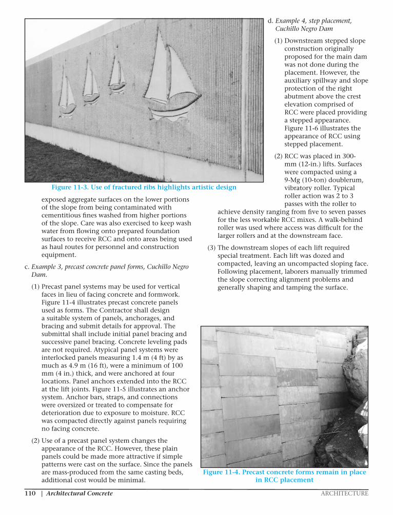
Architectural Concrete ARCHITECTURE|110
exposed aggregate surfaces on the lower portions of the slope from being contaminated with cementitious fines washed from higher portions of the slope. Care was also exercised to keep wash water from flowing onto prepared foundation surfaces to receive RCC and onto areas being used as haul routes for personnel and construction equipment.
c. Example 3, precast concrete panel forms, Cuchillo Negro Dam.
(1) Precast panel systems may be used for vertical faces in lieu of facing concrete and formwork. Figure 11-4 illustrates precast concrete panels used as forms. The Contractor shall design a suitable system of panels, anchorages, and bracing and submit details for approval. The submittal shall include initial panel bracing and successive panel bracing. Concrete leveling pads are not required. Atypical panel systems were interlocked panels measuring 1.4 m (4 ft) by as much as 4.9 m (16 ft), were a minimum of 100 mm (4 in.) thick, and were anchored at four locations. Panel anchors extended into the RCC at the lift joints. Figure 11-5 illustrates an anchor system. Anchor bars, straps, and connections were oversized or treated to compensate for deterioration due to exposure to moisture. RCC was compacted directly against panels requiring no facing concrete.
(2) Use of a precast panel system changes the appearance of the RCC. However, these plain panels could be made more attractive if simple patterns were cast on the surface. Since the panels are mass-produced from the same casting beds, additional cost would be minimal.
d. Example 4, step placement, Cuchillo Negro Dam
(1) Downstream stepped slope construction originally proposed for the main dam was not done during the placement. However, the auxiliary spillway and slope protection of the right abutment above the crest elevation comprised of RCC were placed providing a stepped appearance. Figure 11-6 illustrates the appearance of RCC using stepped placement.
(2) RCC was placed in 300-mm (12-in.) lifts. Surfaces were compacted using a 9-Mg (10-ton) doublerum, vibratory roller. Typical roller action was 2 to 3 passes with the roller to
achieve density ranging from five to seven passes for the less workable RCC mixes. A walk-behind roller was used where access was difficult for the larger rollers and at the downstream face.
(3) The downstream slopes of each lift required special treatment. Each lift was dozed and compacted, leaving an uncompacted sloping face. Following placement, laborers manually trimmed the slope correcting alignment problems and generally shaping and tamping the surface.
EM 1110-1-200931 Oct 97
11-3
Figure 11-3. Use of fractured ribs highlights artistic design
prepared foundation surfaces to receive RCC and onto (2) Use of a precast panel system changes theareas being used as haul routes for personnel and con- appearance of the RCC. However, these plain panelsstruction equipment. could be made more attractive if simple patterns were
c. Example 3, precast concrete panel forms, from the same casting beds, additional cost would beCuchillo Negro Dam. minimal.
(1) Precast panel systems may be used for vertical d. Example 4, step placement, Cuchillo Negrofaces in lieu of facing concrete and formwork. Fig- Damure 11-4 illustrates precast concrete panels used asforms. The Contractor shall design a suitable system of (1) Downstream stepped slope construction orig-panels, anchorages, and bracing and submit details for inally proposed for the main dam was not done duringapproval. The submittal shall include initial panel brac- the placement. However, the auxiliary spillway anding and successive panel bracing. Concrete leveling slope protection of the right abutment above the crestpads are not required. Atypical panel systems were elevation comprised of RCC were placed providing ainterlocked panels measuring 1.4 m (4 ft) by as much as stepped appearance. Figure 11-6 illustrates the4.9 m (16 ft), were a minimum of 100 mm (4 in.) thick, appearance of RCC using stepped placement.and were anchored at four locations. Panel anchorsextended into the RCC at the lift joints. Figure 11-5 (2) RCC was placed in 300-mm (12-in.) lifts. Sur-illustrates an anchor system. Anchor bars, straps, and faces were compacted using a 9-Mg (10-ton) double-connections were oversized or treated to compensate for rum, vibratory roller. Typical roller action was 2 todeterioration due to exposure to moisture. RCC was 3 passes with the roller to achieve density ranging fromcompacted directly against panels requiring no facing five to seven passes for the less workable RCC mixes.concrete. A walk-behind roller was used where access was
cast on the surface. Since the panels are mass-produced
Figure 11-3. Use of fractured ribs highlights artistic design
EM 1110-1-200931 Oct 97
11-4
Figure 11-4. Precast concrete forms remain in place in RCC placement
difficult for the larger rollers and at the downstream leaving an uncompacted sloping face. Following place-face. ment, laborers manually trimmed the slope correcting
(3) The downstream slopes of each lift required the surface.special treatment. Each lift was dozed and compacted,
alignment problems and generally shaping and tamping
Figure 11-4. Precast concrete forms remain in place in RCC placement
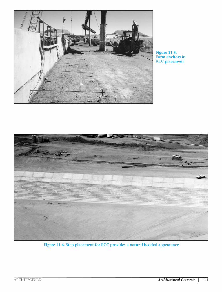
|ARCHITECTURE Architectural Concrete 111
EM 1110-1-200931 Oct 97
11-5
Figure 11-5. Form anchors in RCC placement
Figure 11-6. Step placement for RCC provides a natural bedded appearance
EM 1110-1-200931 Oct 97
11-5
Figure 11-5. Form anchors in RCC placement
Figure 11-6. Step placement for RCC provides a natural bedded appearance
Figure 11-5.Form anchors inRCC placement
Figure 11-6. Step placement for RCC provides a natural bedded appearance
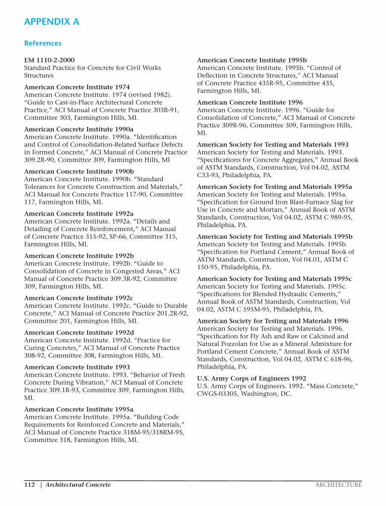
Architectural Concrete ARCHITECTURE|112
EM 1110-2-2000 Standard Practice for Concrete for Civil Works Structures
American Concrete Institute 1974 American Concrete Institute. 1974 (revised 1982). “Guide to Cast-in-Place Architectural Concrete Practice,” ACI Manual of Concrete Practice 303R-91, Committee 303, Farmington Hills, MI.
American Concrete Institute 1990a American Concrete Institute. 1990a. “Identification and Control of Consolidation-Related Surface Defects in Formed Concrete,” ACI Manual of Concrete Practice 309.2R-90, Committee 309, Farmington Hills, MI
American Concrete Institute 1990b American Concrete Institute. 1990b. “Standard Tolerances for Concrete Construction and Materials,” ACI Manual for Concrete Practice 117-90, Committee 117, Farmington Hills, MI.
American Concrete Institute 1992a American Concrete Institute. 1992a. “Details and Detailing of Concrete Reinforcement,” ACI Manual of Concrete Practice 315-92, SP-66, Committee 315, Farmington Hills, MI.
American Concrete Institute 1992b American Concrete Institute. 1992b. “Guide to Consolidation of Concrete in Congested Areas,” ACI Manual of Concrete Practice 309.3R-92, Committee 309, Farmington Hills, MI.
American Concrete Institute 1992c American Concrete Institute. 1992c. “Guide to Durable Concrete,” ACI Manual of Concrete Practice 201.2R-92, Committee 201, Farmington Hills, MI.
American Concrete Institute 1992d American Concrete Institute. 1992d. “Practice for Curing Concretes,” ACI Manual of Concrete Practice 308-92, Committee 308, Farmington Hills, MI.
American Concrete Institute 1993 American Concrete Institute. 1993. “Behavior of Fresh Concrete During Vibration,” ACI Manual of Concrete Practice 309.1R-93, Committee 309, Farmington Hills, MI.
American Concrete Institute 1995a American Concrete Institute. 1995a. “Building Code Requirements for Reinforced Concrete and Materials,” ACI Manual of Concrete Practice 318M-95/318RM-95, Committee 318, Farmington Hills, MI.
American Concrete Institute 1995b American Concrete Institute. 1995b. “Control of Deflection in Concrete Structures,” ACI Manual of Concrete Practice 435R-95, Committee 435, Farmington Hills, MI.
American Concrete Institute 1996 American Concrete Institute. 1996. “Guide for Consolidation of Concrete,” ACI Manual of Concrete Practice 309R-96, Committee 309, Farmington Hills, MI.
American Society for Testing and Materials 1993 American Society for Testing and Materials. 1993. “Specifications for Concrete Aggregates,” Annual Book of ASTM Standards, Construction, Vol 04.02, ASTM C33-93, Philadelphia, PA.
American Society for Testing and Materials 1995a American Society for Testing and Materials. 1995a. “Specification for Ground Iron Blast-Furnace Slag for Use in Concrete and Mortars,” Annual Book of ASTM Standards, Construction, Vol 04.02, ASTM C 989-95, Philadelphia, PA.
American Society for Testing and Materials 1995b American Society for Testing and Materials. 1995b. “Specification for Portland Cement,” Annual Book of ASTM Standards, Construction, Vol 04.01, ASTM C 150-95, Philadelphia, PA.
American Society for Testing and Materials 1995c American Society for Testing and Materials. 1995c. “Specifications for Blended Hydraulic Cements,” Annual Book of ASTM Standards, Construction, Vol 04.02, ASTM C 595M-95, Philadelphia, PA.
American Society for Testing and Materials 1996 American Society for Testing and Materials. 1996. “Specification for Fly Ash and Raw or Calcined and Natural Pozzolan for Use as a Mineral Admixture for Portland Cement Concrete,” Annual Book of ASTM Standards, Construction, Vol 04.02, ASTM C 618-96, Philadelphia, PA.
U.S. Army Corps of Engineers 1992 U.S. Army Corps of Engineers. 1992. “Mass Concrete,” CWGS-03305, Washington, DC.
APPENDIX A
References


![SECTION 034500 - PRECAST ARCHITECTURAL CONCRETE · Architectural precast concrete cladding [and load-bearing] units. ... PRECAST ARCHITECTURAL CONCRETE 034500 ... Architectural Cladding](https://img.pdfslide.net/doc/110x75/5ae006067f8b9a1c248cb77e/section-034500-precast-architectural-concrete-precast-concrete-cladding-and-load-bearing.jpg)