Embed Size (px)
Citation preview
Architectural Modeling in SysML A Practical Approach to Mapping Functions to Logical Architectural Variants
Michael J. Vinarcik, ESEP-Acq, OCSMP-Model Builder—Advanced Booz Allen Hamilton National Defense Industrial Association 18th Annual Systems Engineering Conference October 26-29, 2015

Engineers Love Models!
• What is a Model? – “A simplified or idealized description or conception of a particular
system, situation, or process, often in mathematical terms, that is put forward as a basis for theoretical or empirical understanding, or for calculations, predictions, etc.; a conceptual or mental representation of something. Freq. with modifying word.” – Oxford English Dictionary
• Why do engineers love them? – Reality is often too complicated to “deal with” directly; abstraction hides
complexity and facilitates analysis.
Models Provide Cognitive Leverage

SysML: Systems Modeling Language
• In 2001, the International Council on Systems Engineering established a Model Driven Systems Design workgroup to customize UML for systems engineering.
• By 2006, OMG adopted OMG SysML (the current version is 1.4, adopted in March 2014).
• SysML provides for the following diagram types, with numerous relationship available between model elements: – Behavioral Diagrams: Use case, Activity, Sequence, State Machine – Structural Diagrams: Block Definition, Internal Block, Package – Other Diagrams: Requirements, Package
The System Model
• Other system modeling languages exist, but SysML is the most widely-adopted and has a thriving tool ecosystem.
• A well-constructed system model unambiguously represents a system’s behavior, structure, and interrelationships between elements.
• It also fosters a “crispness” in the formulation of issues (according to David Miller, NASA Chief Technologist).
• In addition, current SysML tools allow the model content to be expressed as tables, matrices, and other derivative work products.

Behavior is at the Heart of Design
• Systems may be characterized by: – The elements of which they are composed – The relationships and interactions between those elements – The behaviors the system exhibits
• Note that systems typically exhibit more functions/behaviors than the component parts can provide individually (otherwise there would be no reason to assemble them into the system).
• It is the desired behaviors (and the conditions under which they are exhibited) that are at the heart of design.
• All requirements are derived products that seek to characterize and communicate the desired behaviors and associated parameters.
Rigorously Define Behavior
• In order to effective design a system, then, one must fully understand the desired behaviors it must exhibit.
• As the behaviors are understood, they must be clearly and unambiguously described.
• This description can then serve as a basis for the creation/derivation of functional and performance requirements.
Property-Based Requirements
• In Model Based Systems Engineering: Fundamentals and Methods (ISBN: 978-1-84821-469-9), Patrice Micouin proposes that all requirements are either: – Structural: related to the composition and structure of a system – Behavioral: related to the behavior/functions of a system – Mixed: a combination of the above types
• He also proposed a property-based requirements model that eliminates the ambiguity associated with text-based requirements (including a syntax for capturing the conditions under which a system must exhibit its functions).

Functional Decomposition
• Functional decomposition is a cornerstone of systems engineering processes.
• Many methods have been used, including functional-flow block diagrams (FFBDs) and IDEF0.
• SysML activity diagrams can be used to fulfill this role and have the added advantage of being easily allocated to logical architectural variants.
• This enhances the utility of the system model by facilitating reuse and end-to-end traceability.
Use Case: The Foundation of Behavioral Understanding
• SysML Use Case Diagrams are a useful starting point for behavior modeling.
• They are simple, easy to understand, and allow the individual or team defining system behavior to sketch the relevant behaviors, actors, and interacting systems.
• This presentation will follow the decomposition of use cases associated with a common, everyday system: a BBQ grill.
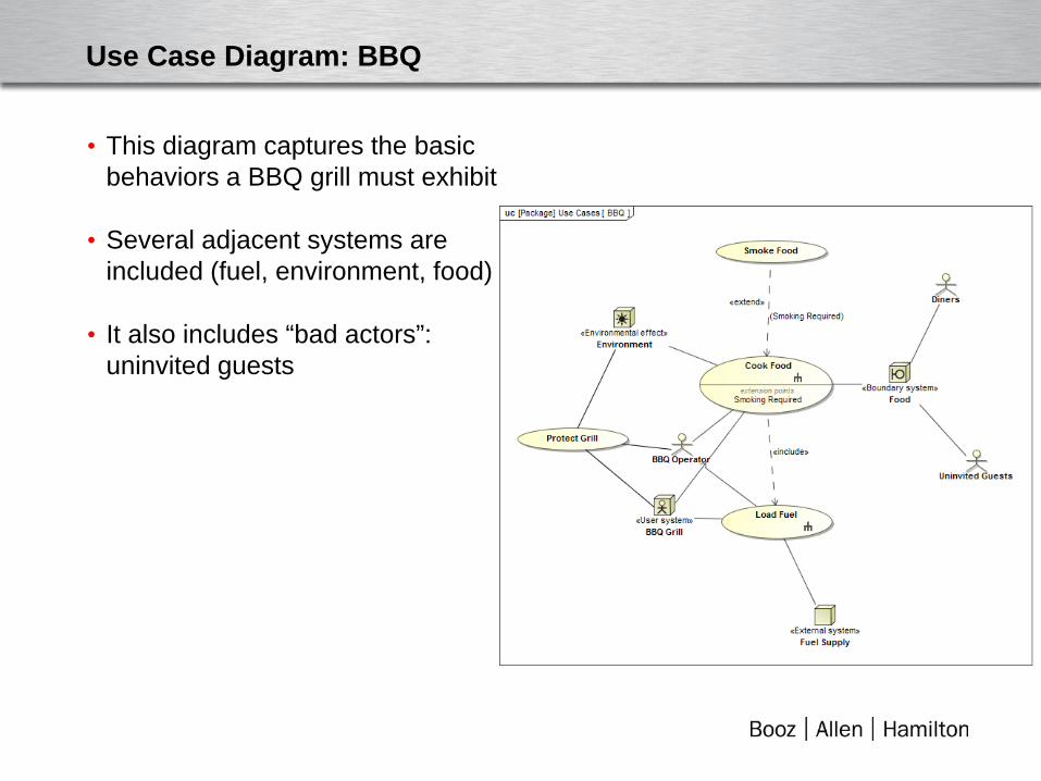
Use Case Diagram: BBQ
• This diagram captures the basic behaviors a BBQ grill must exhibit
• Several adjacent systems are included (fuel, environment, food)
• It also includes “bad actors”: uninvited guests
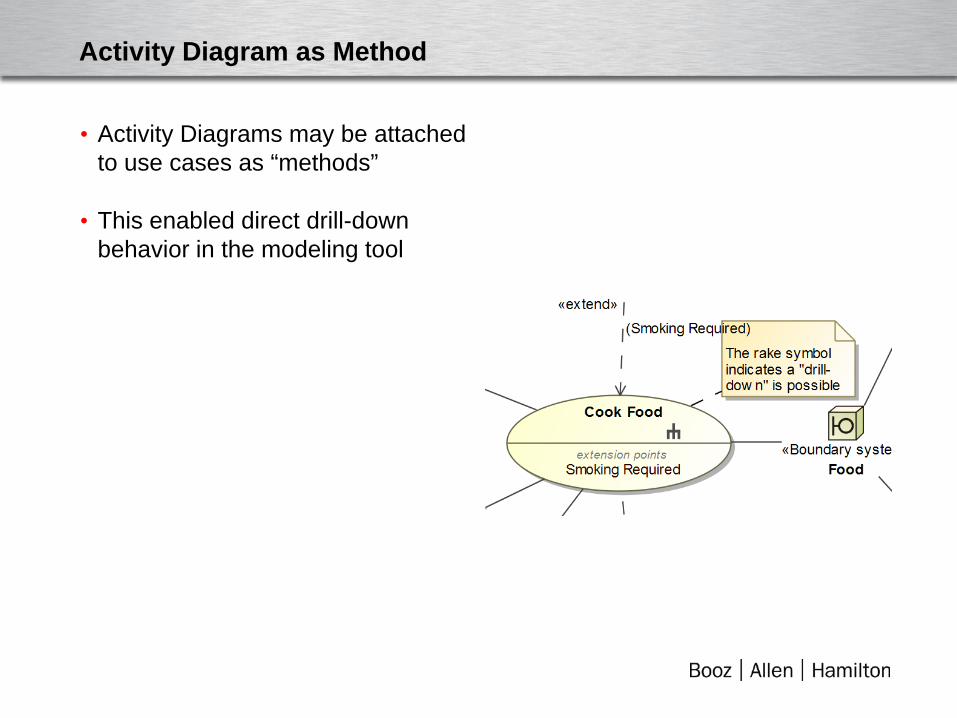
Activity Diagram as Method
• Activity Diagrams may be attached to use cases as “methods”
• This enabled direct drill-down behavior in the modeling tool
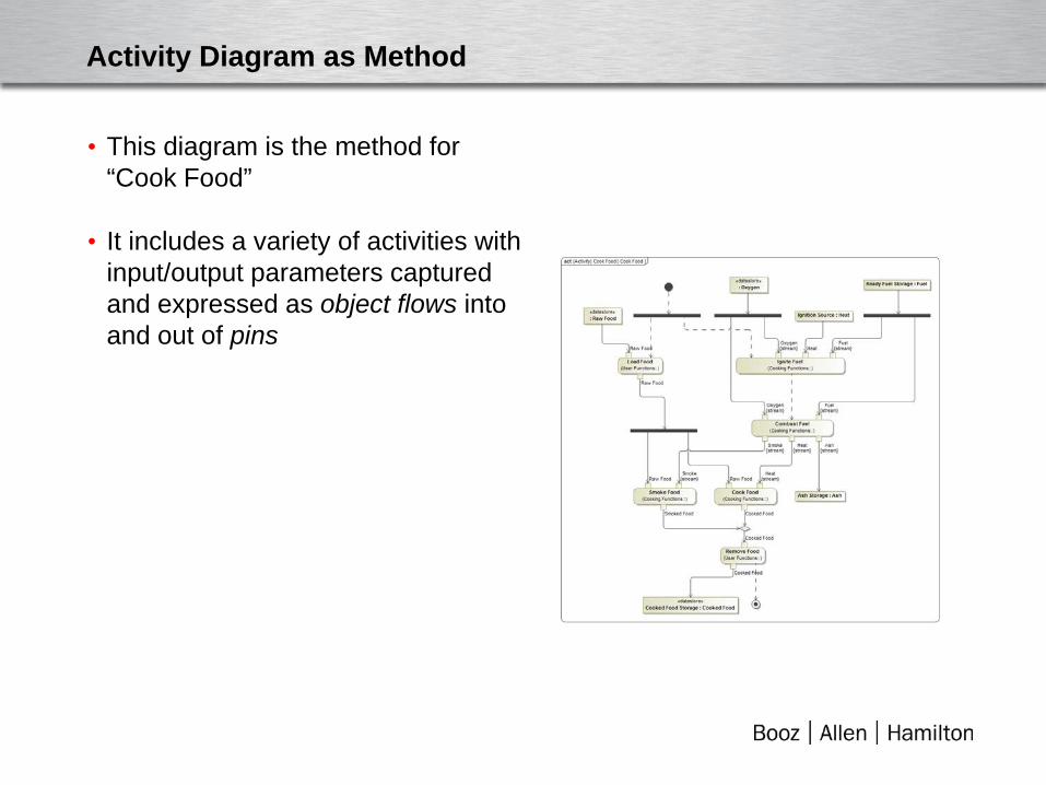
Activity Diagram as Method
• This diagram is the method for “Cook Food”
• It includes a variety of activities with input/output parameters captured and expressed as object flows into and out of pins
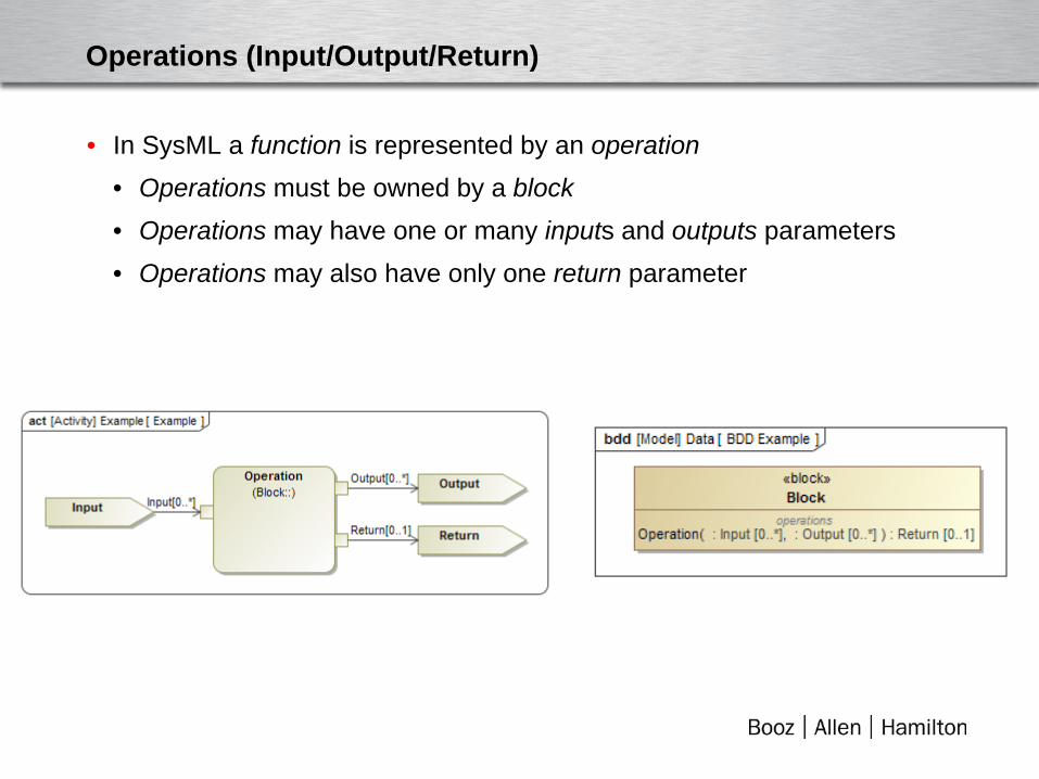
Operations (Input/Output/Return)
• In SysML a function is represented by an operation • Operations must be owned by a block • Operations may have one or many inputs and outputs parameters • Operations may also have only one return parameter
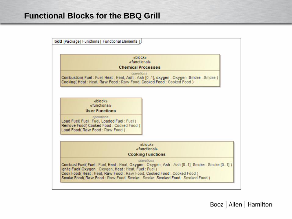
Functional Blocks for the BBQ Grill
Every Activity is a Call Operation
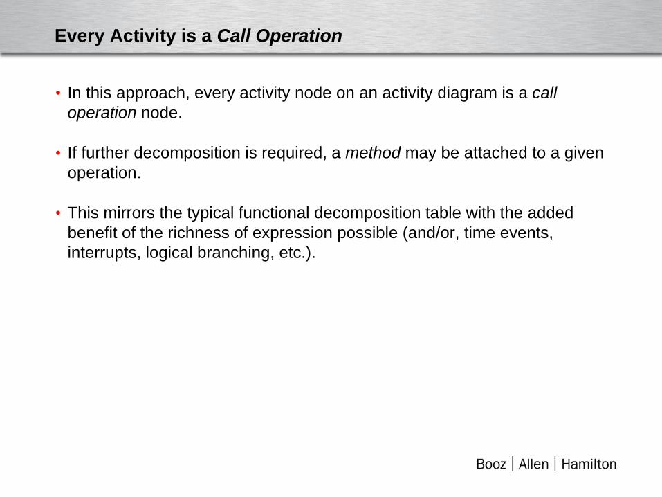
• In this approach, every activity node on an activity diagram is a call operation node.
• If further decomposition is required, a method may be attached to a given operation.
• This mirrors the typical functional decomposition table with the added benefit of the richness of expression possible (and/or, time events, interrupts, logical branching, etc.).
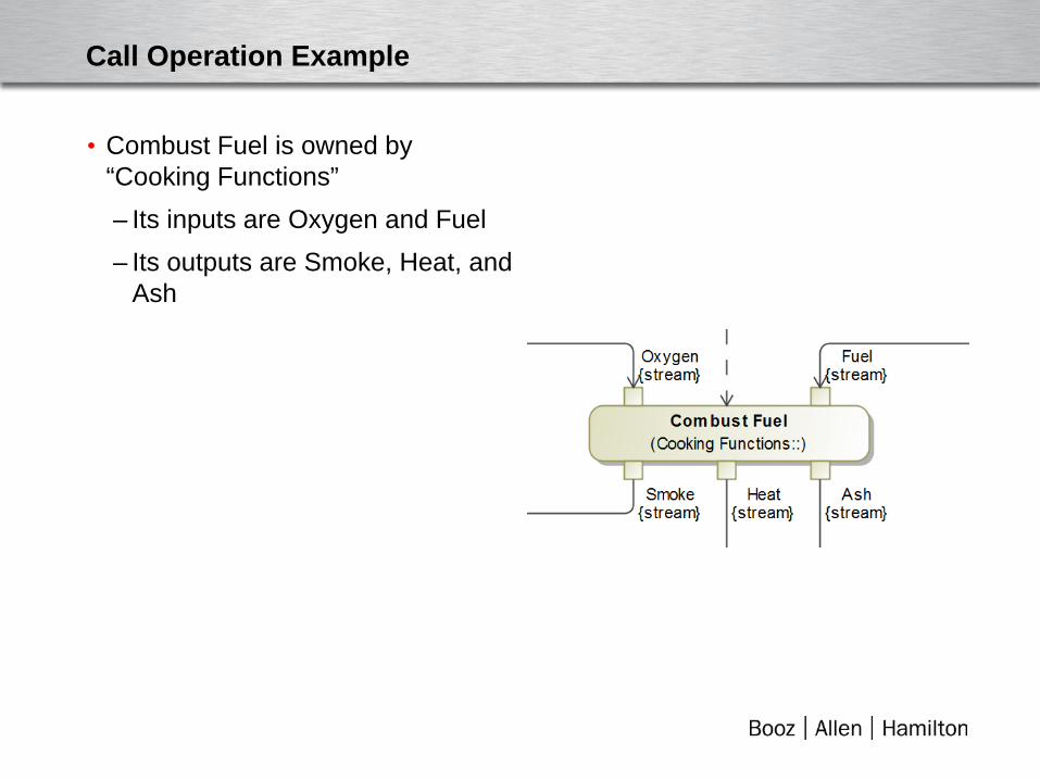
Call Operation Example
• Combust Fuel is owned by “Cooking Functions” – Its inputs are Oxygen and Fuel – Its outputs are Smoke, Heat, and
Ash
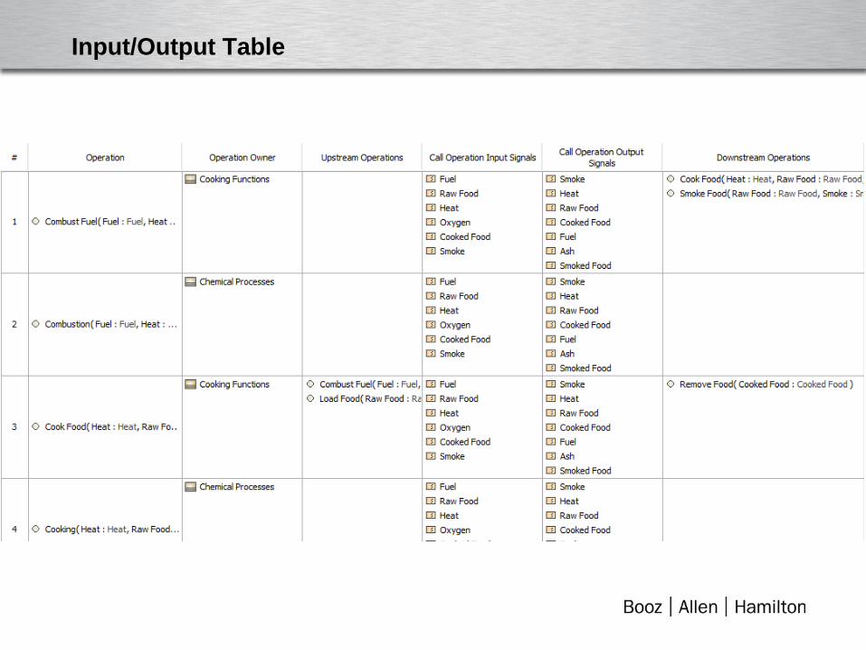
Input/Output Table
Logical Block
• Logical Elements are typed with the <<logical>> stereotype.
• They are then associated with functional blocks via the generalization relationship.
• This allows them to inherit the operations from the functional block (as well as functional requirements satisfied by the operations and any other requirements or model elements linked to the functional block).
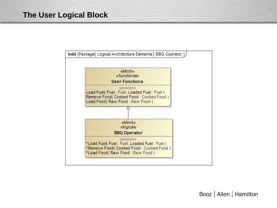
The User Logical Block
Physical Block
• Physical Blocks are similar to logical blocks; they have the <<physical>> stereotype.
• They also may contain properties such as: – Mass – Length/Width/Height – Other physical properties
• Note that they may also inherit attributes and relationships from other blocks.
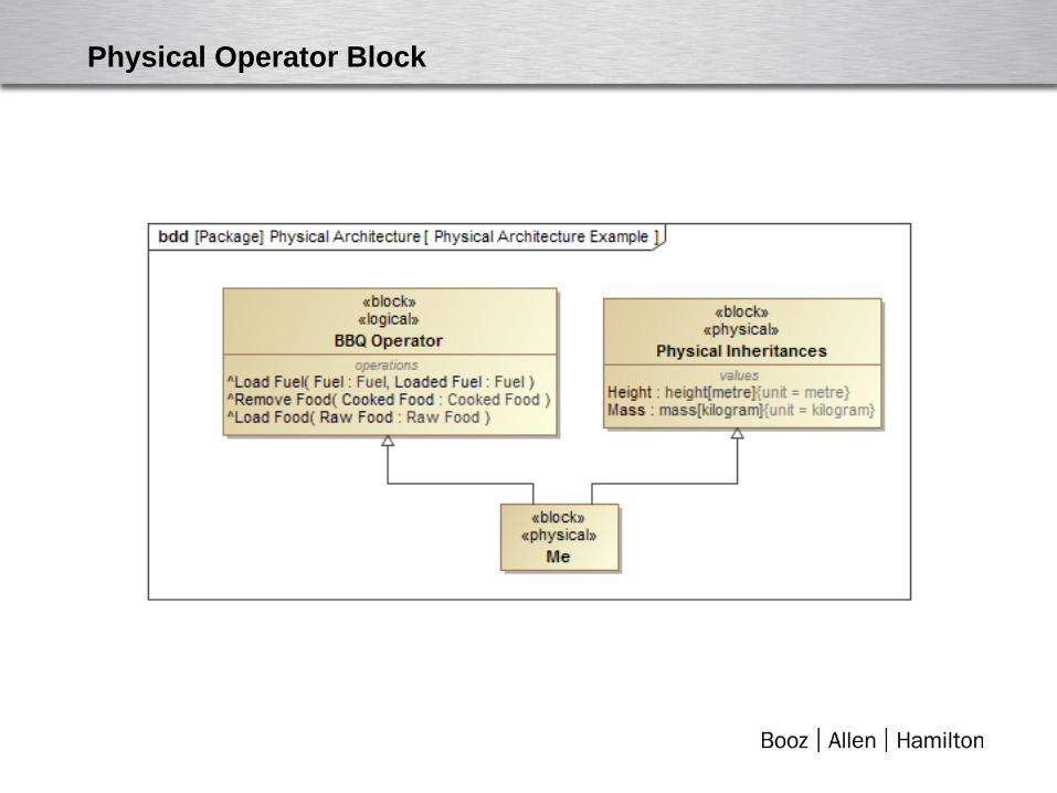
Physical Operator Block
Advantages of Generalization/Specialization
• No allocations: Blocks “own” their functions and attributes.
• Inheritance of relationships: – Functional requirements are satisfied by operations; if a block inherits a
function, it also inherits this relationship – Other relationships (such as value properties satisfying performance
requirements) also inherit
• No allocation relationships are needed…simplifying the modeling effort.

Moving Functions
Smoke Food
moved to a new
functional block

Logical Architecture Example

Pellet Grill Logical Architecture
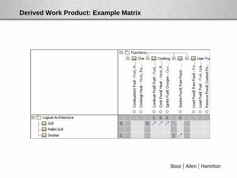
Derived Work Product: Example Matrix
Conclusion
• Using operations is a flexible and straightforward way to accomplish functional decomposition.
• Generalization relationships may be used to inherit functions, requirements, and other relationships from each architecture to the next (functional to logical to physical).
• Derived work products, such as tables and matrices, may be used to manage these relationships and ensure coverage and traceability.