Embed Size (px)
Citation preview
Architectural Support for Designing Fault-Tolerant Open Distributed Systems
Salim Hariri and Alok Choudhary, Syracuse University
Behcet Sarikaya, Bilkent University
A distributed voting algorithm and a two-
level hierarchy for permanent memory are
key elements in this scheme for supporting fault tolerance in open
distributed systems.
distributed system consists of autonomous computing modules that inter- act with each other using messages. Designing distributed systems is more difficult than designing centralized systems for several reasons. Physical
separation and the use of heterogeneous computers complicate interprocessor communication, management of resources, synchronization of cooperating activ- ities, and maintenance of consistency among multiple copies of information. The main advantages of distributed systems include increased fault-tolerance capabil- ities through the inherent redundancy of resources, improved performance by concurrently executing a single task on several computing modules, resource sharing, and the ability to adapt to a changing environment (extensibility).’
Distributed systems cover a wide range of applications. Recent advances in VLSI devices and network technology will further increase the use of distributed systems. As the complexity of these systems increases, so does the probability of component failure, which can adversely affect the performance and usefulness of such systems. Thus, reliability, availability, and fault tolerance become important design issues in distributed systems. Fault tolerance is the system’s ability to continue executing despite the occurrence of failures. Increasing the reliability and fault tolerance of a system involves a trade-off between the cost of failure (for example, costs incurred by incomplete or incorrect computations) and the cost of incorporating redundancy and recovery mechanisms.
Because of their inherent redundancy, distributed systems provide a cost- effective way to apply fault-tolerance techniques. Open distributed systems pro- vide universal connectivities among their components because their designs are based on the standard protocols adopted by the International Standards Organi- zation (ISO). In this computing environment, interacting processes communicate through messages that traverse a stack of software layers. Consequently, applying fault-tolerance techniques to execute critical tasks can be costly in terms of execution time.
In this article, we first provide an overview of the main techniques for designing
50 0018-9162/92/0600-0050$03.00 0 1992 IEEE COMPUTER
fault-tolerant software and hard- ware systems. We identify the important features of the build- ing blocks (computers, memo- ries, buses, etc.) that can sup- port an efficient implementation of fault-tolerant open distribut- ed systems (FTODS). Taking into account the features of these building blocks, we propose an organization for FTODS. In FTODS, the algorithms needed for transferring files and syn- chronizing the concurrent activ- ities of the computing modules - and for recovery - are IS0 standard protocols. We propose the use of low-level voting and recovery algorithms that can run as a layer of software above the operating system to make the open distributed system an at- tractive environment for apply- ing fault-tolerant techniques.
Design considerations for fault tolerance
Glossary of acronyms
AAT - Atomic action tree ACSE - Association control service etement ASE - Applk&ion ~rviee element CCR - Commitment, concurrency, and recovery DVA - Dtstrtbuted vating algorithm FTAY - Ftle transfer and nrana~ent PTMP - Fault-&Want muitipnxessor P’TODS - Fault-toterant open distributed systems HPM - HterarchW permanent memory JTM -Job transfer and manipulation MPM - Magnet& permanent memory WTF - Mean time to failure ODP - Open distributed processing ODS - Open distributed systems OSI - Open Systems tnterconnection RDA - Remote database access StFT - &&ware-imptemented fault tolerance WU - Semiconductor permanent memory TP - Traffsactk3n processing Wt - Transaction reliabikty VTP - Virtual terminai protocol
the design to concurrently mask faults and prevent their propagation to other modules. The most common example of static redundancy is the triple modular redundant system. Another approach
Fault tolerance, a system’s ability to for providing fault tolerance is dynamic continue executing its tasks despite the redundancy, which uses spare compo- occurrence of failures, can be achieved nents to replace faulty modules once by fault masking. Masking (also called they are detected. Still another approach static redundancy) is incorporated into - a combination of these two, called
Strategies for designing fault-tolerant computers
Many techniques have been used to build fault-tolerant computers. They include
Fault masking: Concurrent masking and correction of gen- erated errors.
Fault defe@o#: Use of hardware and software mechanisms to determine the Qccurrence of a failure. Fault detection mechanisms include concurrent fault detection, stepwise com- parison, and periodic testing to determine whether computers or communication links are operating correctly.
Fault containment: Prevents propagatlun of errQneQus or damaged information In the system after a fault occurs and before it is detected.
F&t diagnosis: t&cates and identifies the faulty module re- sponsible for a detected error.
Repair/recontisuration: Eliminates or replaces the faulty module, or provides means to bypass it.
Fault recovery Corrects the system to a state acceptable for continued operation.
Most of these techniques have been used to build such computers as the Tandem 16 NonStop system, the Stratus
hybrid redundancy - applies static and dynamic redundancy to achieve fault tolerance. In general, the design of a fault- tolerant computer involves one or more of the following strate- gies: fault masking, fault detec- tion, fault containment, fault diagnosis, repairlreconfigura- tion, and fault recovery2 (see the sidebar “Strategies for de- signing fault-tolerant comput- ers”).
Designing a fault-tolerant dis- tributed system is more involved than designing a fault-tolerant centralized system. Two main problems must be addressed during design:
(1) Concurrency control, which involves scheduling con- current execution of tasks on different nodes such that their results are identical to a serial execution of the tasks (serializ- ability requirement).
(2) Kedundancy management, which involves preserving consistency among replicated resources and maintaining the state information with backup mod- ules to support recovery.
Transactions are an important pro- gramming paradigm for simplifying the design of reliable distributed applica-
computer system, the VAXft 3000, the Teradata and Sequoia systems, the fault-tolerant multiprocessor (FTMP), the soft- ware-impfemented fault-toterance (SIFT) system, and AT&T’s Electronic Switch System (ESS).ls The effectiveness of fault- tolerance techniques can be measured by the “coverage,” de- fined as the conditional probability of recwering from a fautt once it occurs.3 It Is difficult to measure this param&X be- cause it involves evaluating the probability that fauft detec- tion, fault diagnosis, repairlrrrconfiguration, and recovery al- gorithms are aperating correctly.
References
1. D.P. Siewiorek and R.S. Swarz, The Theory and Practice of&IL able System Ckwign Digital Press, Bedford, Mass., 1982.
2. D.P. Siewiorek, “Fault Tabrance in Commercial Computers;” Computer, Vol. 23, No. 7, July lQQ0, pp. 28-37.
3. J.B. Dugan and KS. Trivedi, ‘Coverage Modeling of Fault-Toter- ant Systems,” IEEE Tmns. Computers, Vol. C-38, No. 6, June 1989, pp. 775-787.
June 1992 51
trol can be centralized or decentralized,
Transactions depending on whether the voting is done at one site or multiple sites.’ In addition to maintaining consistency of replicat-
A transaction can be defined as a collection of operations having the following three properties’:
ed resources, redundancy management is responsible for system recovery in the
Failure atomicify: Either all operations are performed successfully or their re- suits are undone when a failure occurs.
presence of node crashes and communi- cation link failures.
Permanence: The results of committed transactions will not be lost.
Serializability: The results of executing transactions concurrently are the same as if they were executed serially.
Use of the transaction concept to model distributed computations provides a convenient means to solve the concurrency control and redundancy management problems.’ The concurrency control problem consists of three tasks: assigning an order to all transactions, identifying conflicting transactions, and synchronizing transactions to resolve the identified conflicts. Basically, there are three ap- proaches to concurrency control: time-stamp-based schemes, locking protocols, and optimistic techniques.2
References
1, Distributed Systems, S. Mullender, ed., Addison-Wesley, Reading, Mass., 1989.
2. P.A. Bernstein, V. Hadzilacos, and N. Goodman, Concurrency Control and Recovery in Database Systems, Addison-Wesley, Reading, Mass., 1987.
tions (see the “Transactions” sidebar). Techniques for managing redundancy and maintaining consistency of repli- cated objects are broadly character- ized as centralized- and decentralized- control algorithms. The centralized- control approach supports strong con- sistency, requirements and prevents deadlocks, but it is susceptible to single points of failure. The decentralized-con- trol approach supports weak consistency requirements (when it is permissible to have the state of some rep- lica out of date for a short period of time), and there- fore it can potentially in- crease a system’s through- put. The primary-copy algorithm’ applies the cen- tralized-control strategy to ensure the consistency of replicated resources. In this scheme. one node is desig- nated as the primary node and made responsible for serializing updates. When the update values have been computed, the primary node broadcasts them to all oth- er nodes in the system. The primary node then waits to receive acknowledgments
Voting algorithms have also been used to ensure consistency of replicated re- sources. In this scheme, managers of replicated resources use a common set of rules to determine whether an up- date can be made. The algorithm’s con-
layered architecture.’ IS0 committees are working on an architecture in line with the reference model for open dis- tributed processing (ODP). This effort aims to combine the OS1 model with a database model to arrive at a global framework for designing distributed systems. In such an environment, any computer would be open for communi- cation and could be integrated easily with the existing distributed systems to perform certain tasks. Implementation of the communication protocols as lay- ered software tends to be very slow and consequently limits the scope of appli-
cations for open distrr%ut- ed systems.
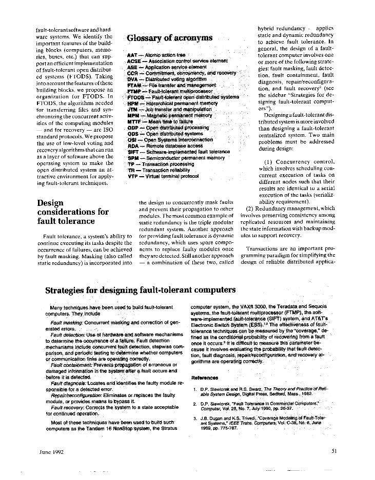
Figure 1. The structure of an application layer.
The application layer is implemented as several ap- plication service elements (ASEs), with one ASE serving them all. This ele- ment is called the associa- tion control service element (ACSE). and it provides association (connection) es- tablishment/disconnection service to other ASEs. In open distributed systems, distributedapplicationsare implemented by the servic- es that the ASEs provide. The application layer ser- vices can be in the form of file transfers using the FTAM (file transfer and management) protocol, re- mote database access using
52 COMPUTER
from all nodes before processing the next transaction. The main problem with this scheme is that it permits no paral- lelism among transaction executions.
Open distributed systems
In this article, we investigate tech- niques for providing architectural sup- port to improve the execution of dis- tributed applications that use the Open Systems Interconnection standards. The main goal of the OS1 reference model is to provide universal connectivity among heterogeneous computers. The refer- ence model is designed to structure com- munication hardware and software in a
the RDA protocol, job transfers using the JTM (job transfer and manipula- tion) protocol, a virtual terminal using the VT protocol, and transaction pro- cessing using the TP protocol.
To achieve reliable and fault-tolerant computing in open distributed systems, the ASEs use the commitment, concur- rency, and recovery (CCR) services pro- vided by a special ASE called the CCR protocol.4 CCR is a standard two-phase commit protocol that provides the ser- vices needed to achieve concurrency control and recovery during execution of application layer tasks such as FTAM, TP, VTP, etc. Figure 1 shows the OS1
communication model and the interac- tions among the ASEs of the applica- tion layer.
Architectural support for FTODS
In this section we identify features that should be supported by the com- puting modules of open distributed sys- tems to facilitate an efficient implemen- tation of fault-tolerant algorithms. On the basis of this criteria, we propose an organization for fault-tolerant open dis-
FTODS computing module capabilities
tributed systems, the architecture of its building blocks, and the required algo- rithms and protocols. The architecture of the computing modules should sup- port reliable broadcasting, self-repair/ recovery, selective fault tolerance, and permanent memory (see the sidebar “FTODS computing module capabili- ties”).
Organization of the FTODS. An FTODS comprises a set of computing modules we refer to as nodes. Nodes communicate and interact with each other by broadcasting their messages on a redundant broadcast medium. A
The architecture of the computing modules should faciltate erations in a Sault-tolerant mode and tile rest in a normal the efficient implementation of fault-tolerant dgorithms. This mode. This will lead to a signfficant imprcwement in peIfOf- architectural support can be provid%d by the following capa- mance without compromising the fault-tdtrrance fequife-
bilities: ments. Conseguentiy, the arGh&otur% Of the computing mod-
Reliabk brcmdmksttng. Reliable broac&asting provides ules should support ~~~~,r~gu~~~n such that the
means for a set of procasses to communicate in spite of fail- processors Mthin a nod% can be canfigured for use as a
ures and is used frequently as a priiitive operation to fmple- masking redundancy during eMGal operations and as a muiti-
ment reliable distributed appliGation8.l it has been shown that processor system during noftG&Gal operations. This capabifi-
reliable broadcasting provides an efficient soft&ion to many ty has been supported by the G.vmp, which contairis three
problems - for example, distributed consensus, distributed processor-memory pairs that can operate independently and
synchronization, replicated update; and transaction manage- can also providot fault-&&rant 0p%rations.4
ment in database systems.* Furthermore, theee r&able pfo- HhmmhW pmnaqemt nxmwy aystesn. Most fecrrvsry tocols will run efficiently on the underlying architecture if its communication n%twGrk has a broadcast capab&ty.
aigofithms needed to a~M?v% @Moferant computing rety on permanent storage.’ St&&e st%f&ge is usad to stofe the
S%if-~6pai~ke~ov%~. Recovery in distributed systems with chsckpoints of a system stat%: these ch%ekpoints will b% used
replicated resourcss, GOmputatlons, and database systems is to restore the system to the previous faoft-free checkpoint
a nontrivial task. Moreover, the ov&!%ad of recovery can de- state when a failure oc~ufs duthtg normal operation. Stable
grade system performanc% significantiy.2 Hardware recovery storage is normally COnStrUCted using dual magnetic disks.
blocks have been proposed to reduce overtmad during the Performance of fautt-tolerant algorithms Gan be improved sig-
save operations of system state &nd to speed up recovery nificantly if stab& morage is implemented in a twa-tevel hier-
when faults are de&&d in a mu&iproG%ssor sy&%m.3 The tit- arGhy in which sem&8nd&tGtor plsrnranen memory is used in
erature is rich with techniqt#s that can be used ttj support the first level and magnrttic permanent memory is us%d in the
self-repair and reG0vef-y. For exampie, the us% of static re- second. The SPM acts ae a buffef b%twe%n the professor
dundancy.to achieve fault masking has been used in’the and the t&PM.
c.vmp (computer-voted multiprocessor) computer.* Atso, Kuhl and Reddy” have addressed fauft,diagnosis at the system ft%fer%nG%s level and the conditions under which nodes cefl diagnose the failure of other nodes to achieve s&f-test. 1. u&ributed Sy&ms, 8. MutMUer, ed., Add&on-Wesley, Read-
The architecture of the computrng modules should support tng, Mass., 1989. a hierarchical approach for r%cOv%ry such that mbst of the 2. time-consuming tasks are ex%Gut%d at a lower level of this hi-
J. Chang and f&F. MsxemBwk, uRs&bts 6roatlcast Protocols, ACM Tams. Com@#er @@ems, VG~. 2, No. 3, Aug. 1984, pp.
erarchy. The use of staticz (masking) redundancy and diag- nostic routines simpl@iis the tasks involved in fault detection, self-reconfiguration and repair, and recovery. Providing the computing modules with these features cot&d sign$fkant#y re-
251-273.
3. Y.-H. Ies and KG. Shfn, Qestgn and Evaluation of a Fault-Toler- ant ~~ Using ~s~~~ EfJocks,” MZE Tram Computers, V#. G33,No. 2, Feb. lm, pp. t13-124.
duce the complexity of recovery at the application Isvel. With the proliferation of VLBI chips, I/O processors, eontiolters, and memory, it is now reasonable to use redundant compo- nents in designing th8 computing modules.
Sekstive fault tobrane. Since not all task operations re-
4. D.P. Siswiorek and R.S. Swsrz, The Theow and Pracrice of Reli- ebbs system Lwgn, @gital Press, Seuford, Maas., 1982.
5. J.G. Kuhl and SM. F&d&y, %sutt4.Xsgnosis in Fully Distrsbutetd Systems,” Pm@. 1 l@ Iti‘i SJM~P. Fs&-Toisrsnt Gompuffi@ IEEE CS Press, Los A&m&s, C&if., Order No. 350 (microfiche only),
quite fault tolerance, it is desirabIe to run on[y the critical op- June 1981, pp. lOO-f05.
June 1992 53
r---‘-----------‘-‘--~------------.----------......----------.---..------..-----------.----,
Cluster 1
.I + Intercluster bus I ________________________________________-- - - - - - - - - - - - - - . . . - - - - - - - - - - - - - . - - - - - - - - - - - - - . - - - ,
Cluster n
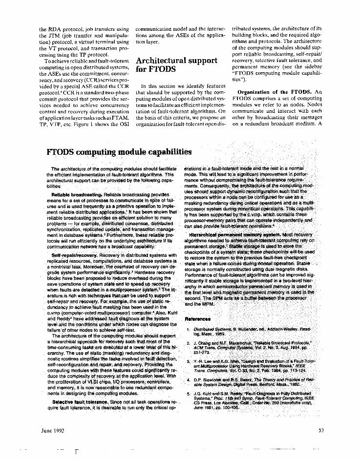
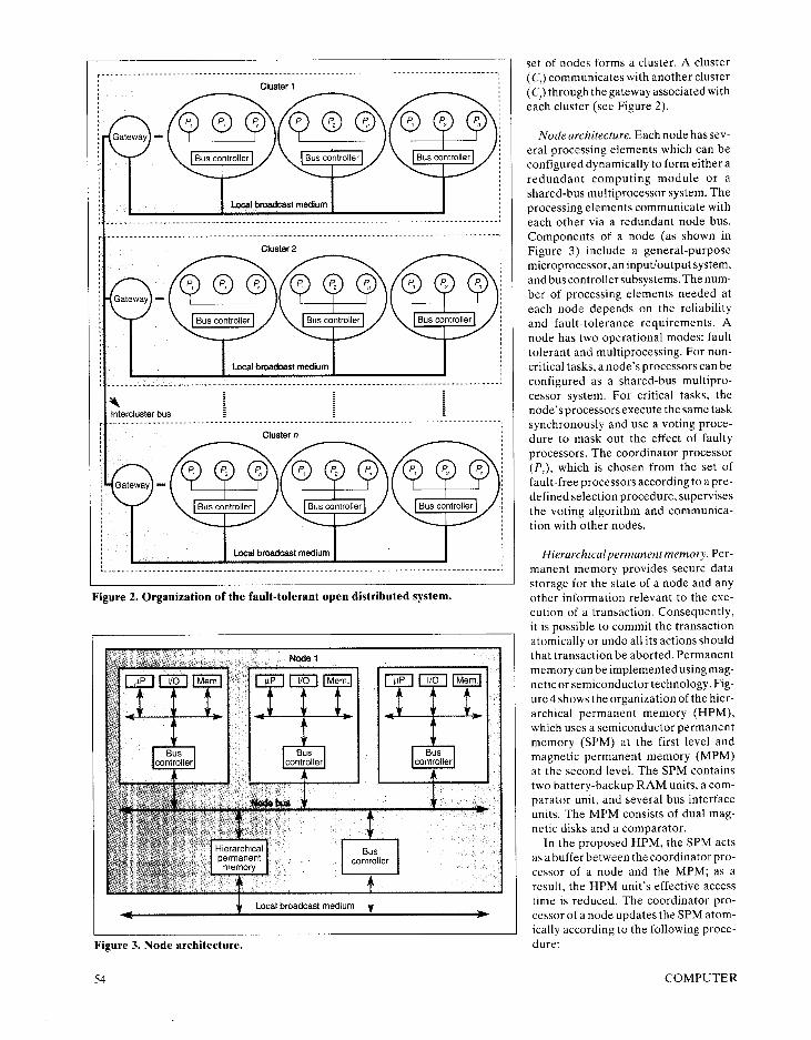
F igure 2. Organ iza t ion of the fault- tolerant o p e n distr ibuted system.
F igure 3. N o d e archi tecture.
5 4
set ot n o d e s to rms a cluster. A cluster (C,) commun ica tes with another c luster (C,) th rough the ga teway assoc ia ted with each cluster (see F igure 2).
N o d e archi tecture. E a c h n o d e hassev- e ra1 process ing e lements wh ich can b e conf igured dynamica l ly to fo rm ei ther a redundant comput ing m o d u l e o r a shared-bus mul t ip rocessor system. The process ing e lements commun ica te with each other v ia a redundant n o d e bus. Componen ts of a n o d e (as shown in F igure 3) inc lude a genera l -pu rpose microprocessor , a n input/output system, a n d bus contro l ler subsystems. The n u m - ber of p rocess ing e lements n e e d e d at each n o d e depends o n the rel iabi l i ty a n d faul t - to lerance requi rements . A n o d e has two operat iona l modes : fault to lerant a n d mul t iprocessing. For non - cri t ical tasks, a n o d e ’s processors can b e conf igured as a shared-bus mul t ipro- cessor system. For cri t ical tasks, the n o d e ’s processors execute the s a m e task synchronous ly a n d use a vot ing p roce- du re to m a s k out the effect of faulty processors. The coord inator p rocessor (P,), wh ich is chosen f rom the set of fault- free processors accord ing to apre - def ined select ion procedure , superv ises the vot ing a lgor i thm a n d commun ica - t ion with other nodes.
H ie ra rch ica lpermanentmemory . Pe r - manen t m e m o r y prov ides secure data s torage for the state of a n o d e a n d any other in format ion re levant to the exe- cut ion of a transact ion. Consequent ly , it is poss ib le to commi t the t ransact ion atomical ly o r u n d o al l its act ions shou ld that t ransact ion b e abor ted. Pe rmanen t m e m o r y can b e imp lemen ted us ing m a g - net ic o r semiconduc tor technology. F ig- u re 4 shows the organizat ion of the h ier - arch ica l pe rmanen t m e m o r y (HPM) , wh ich uses a semiconduc tor pe rmanen t m e m o r y ( S P M ) at the first level a n d magnet ic pe rmanen t m e m o r y ( M P M ) at the second level. The S P M conta ins two bat tery-backup R A M units, a com- parator unit, a n d severa l bus interface units. The M P M consists of dua l m a g - net ic d isks a n d a comparator .
In the p roposed H P M , the S P M acts as a buffer be tween the coord inator p ro- cessor of a n o d e a n d the M P M ; as a result, the H P M unit’s effective access tim e is reduced. The coord inator p ro- cessor of a n o d e updates the S P M a tom- ical ly accord ing to the fo l lowing proce- dure:
C O M P U T E R
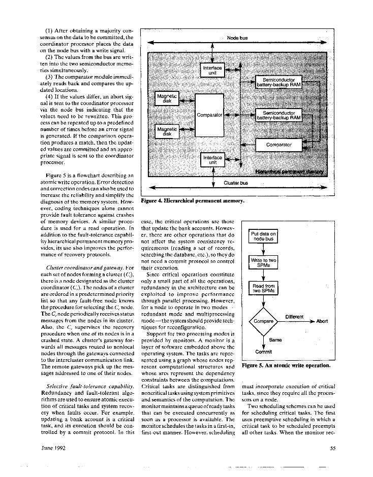
(1) After obtaining a majority con- sensus on the data to be committed, the coordinator processor places the data on the node bus with a write signal.
(2) The values from the bus are writ- ten into the two semiconductor memo- ries simultaneously.
(3) The comparator module immedi- ately reads back and compares the up- dated locations.
(4) If the values differ, an abort sig- nal is sent to the coordinator processor via the node bus indicating that the values need to be rewritten. This pro- cess can be repeated up to a predefined number of times before an error signal is generated. If the comparison opera- tion produces a match, then the updat- ed values are committed and an appro- priate signal is sent to the coordinator processor.
Figure 5 is a flowchart describing an atomic write operation. Error detection and correction codes can also be used to increase the reliability and simplify the diagnosis of the memory system. How- ever, coding techniques alone cannot provide fault tolerance against crashes of memory devices. A similar proce- dure is used for a read operation. In addition to the fault-tolerance capabil- ity hierarchical permanent memory pro- vides, its use also improves the perfor- mance of recovery protocols.
Cluster coordinator and gateway. For each set of nodes forming a cluster (C,), there is a node designated as the cluster coordinator (C,). The nodes of a cluster are ordered in a predetermined priority list so that any fault-free node knows the procedure for selecting the C, node. The C, node periodically receives status messages from the nodes in its cluster. Also, the C, supervises the recovery procedure when one of its nodes is in a crashed state. A cluster’s gateway for- wards all messages routed to nonlocal nodes through the gateways connected to the intercluster communication link. The remote gateways pick up the mes- sages addressed to one of their nodes.
Selective fault-tolerance capability. Redundancy and fault-tolerant algo- rithms are used to ensure atomic execu- tion of critical tasks and system recov- ery when faults occur. For example, updating a bank account is a critical task, and its execution should be con- trolled by a commit protocol. In this
June 1992
Node bus
Figure 4. Hierarchical permanent memo] rY*
case, the critical operations are those that update the bank accounts. Howev- er, there are other operations that do not affect the system consistency re- quirements (reading a set of records, searching the database, etc.), so they do not need a commit protocol to control their execution.
Since critical operations constitute only a small part of all the operations, redundancy in the architecture can be exploited to improve performance through parallel processing. However, for a node to operate in two modes - redundant mode and multiprocessing mode-the system should provide tech- niques for reconfiguration.
Support for two processing modes is provided by monitors. A monitor is a layer of software embedded above the operating system. The tasks are repre- sented using a graph whose nodes rep- resent computational structures and whose arcs represent the dependency constraints between the computations. Critical tasks are distinguished from noncritical tasks using system primitives and semantics of the computation. The monitor maintains a queue of ready tasks that can be executed concurrently as soon as a processor is available. The monitor schedules the tasks in a first-in, first-out manner. However, scheduling
Abort
Same
Commit
Figure 5. An atomic write operation.
must incorporate execution of critical tasks, since they require all the proces- sors on a node.
Two scheduling schemes can be used for scheduling critical tasks. The first uses preemptive scheduling in which a critical task to be scheduled preempts all other tasks. When the monitor rec-
55
ognizes that the next task is critical, it preempts the tasks on other processors. In the second scheme, the monitor waits for all current tasks to complete before scheduling a critical task, and it does not schedule any noncritical tasks dur- ing that period, even if processors are available. The first scheme has the ad- vantage that critical tasks are complet- ed as soon as possible. But the overhead of preempting tasks can be significant because the state of all the current pro- cesses must be saved. The second scheme does not require saving the states of the current processes, but the processors may remain idle for a long period, re- ducing utilization and throughput.
Distributed voting algorithm. In our analysis, we assume that a faulty pro-
cessor either stops producing data (fail- stop model) or produces corrupted data that the voting algorithm can recognize and use as a symptom of a faulty proces- sor. Processor faults can be caused by a malfunction of its hardware and/or soft- ware. A processor can assume only two states: faulty or fault free. During the fault-tolerance mode of operation, a node’s processors are configured to ex- ecute the same task (static redundancy) and the system memory is reconfigured as a hierarchical permanent memory. A coordinator processor (PC) is associated with each node. The PC supervises the distributed voting algorithm and com- mits the tasks’ execution. Selection of the P, follows a predefined procedure. For example, if each processor is identi- fied by a number (ID), then PC can be
selected as the fault-free processor with the maximum ID value.
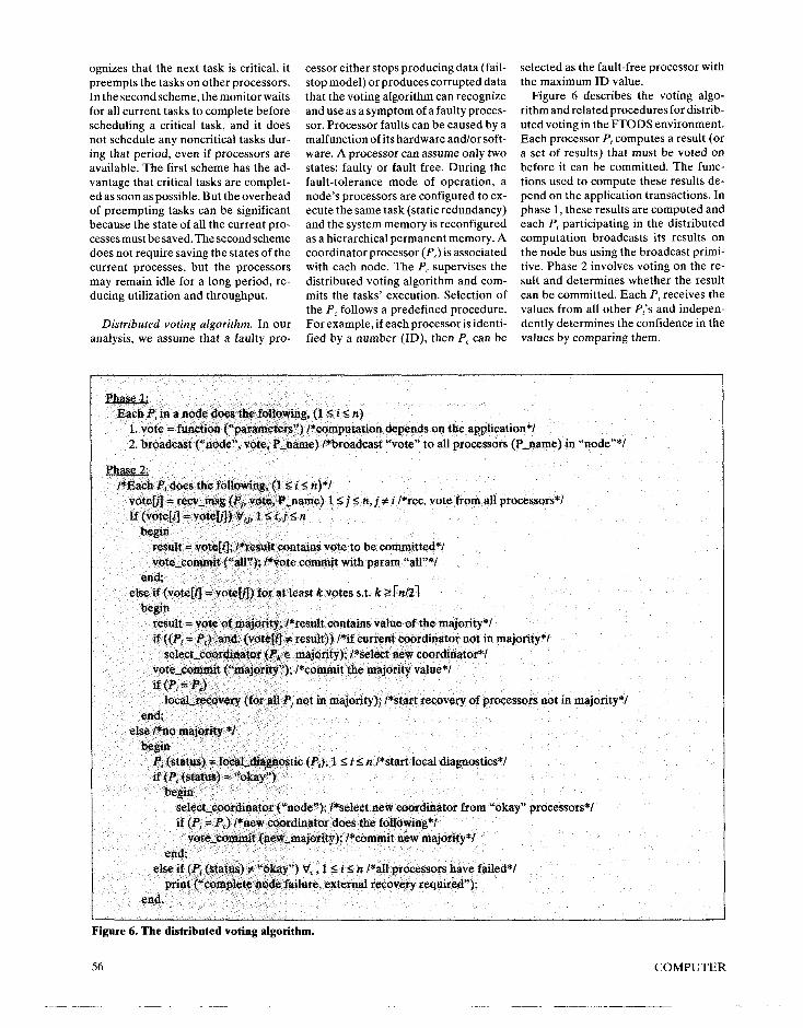
Figure 6 describes the voting algo- rithm and related procedures for distrib- uted voting in the FTODS environment. Each processor P, computes a result (or a set of results) that must be voted on before it can be committed. The func- tions used to compute these results de- pend on the application transactions. In phase 1, these results are computed and each Pi participating in the distributed computation broadcasts its results on the node bus using the broadcast primi- tive. Phase 2 involves voting on the re- sult and determines whether the result can be committed. Each Pi receives the values from all other Pi’s and indepen- dently determines the confidence in the values by comparing them.
Each Pi in a node does the f&owing, (15 i 5 n) 1. vote = function (“parameters”) /*computation de-pends on the appiication*/ 2. broadcast (“node”, vote, P-name) /*broadcast “vote” to all proc&sors (P-name) in “node”*/
te, P-name) 1 I j I n, j f i /*rec. vote from all processors*/ /*Each Pi does the foliowinf
vote01 = recv,msg (Pi, vo If (vote[i] = voteb]) Ff, 1 i i, j r; PI
begin result = vote[i]; &es&# contains vote to be committed*/ vote-commit (“all”); /*vote commit with param *all”*/
end; else if (voteM = votetn) for at least k votes s.t. k r [n/21
begin result = v?te of maj@y; I*resuit contains value of the majority*/ if ((Pi = PC) -and. (votefil f result)) /*if current coordinator not in majority*/
select-coordinator @$ e majority); /*select new coorditiator*l vote-commit (“rmajority”); /*commit the majority value*/ if (P, = P,)
local-recovery (for all P, not in majority); /*start recovery of processors not in majority*/ end,
else I*no majority *I b&
Pi (status) = lacal_ctiegnostic (Pi), 1 S i s n /*start local diagnostics*/ if (Pi (status) = “okay”)
begin select-coordinator (“node”); /*select new coordinator from “okay” processors*/ if (Pi = PC) /*new coordinator does the following*/
vote,tzmMt (new-majority); /*commit new majority*/ end;
else if (P< (status) _ _ -If , .,,- - _-.-. --‘r _---------_.-- - ---- print (“comp&~ node failure, external recov&-y requi&d”);
end.
Figure 6. The distributed voting algorithm.
56 COMPUTER
There can be three possible outcomes of this comparison. First, all values match with each other - a complete consen- sus. In this case, the coordinator proces- sor P, broadcasts the result to all P,‘s. Each P, acknowledges by sending a broadcast acknowledge message, and the result is written in the permanent memory.
In the second outcome, only a major- ity is obtained on the result and the values of some P,‘s do not agree with that of the majority. In this case, there are two groups of processors, those be- longing to the majority and those that don’t. Since a majority is sufficient to commit a new value, the distributed voting algorithm (DVA) is executed such that it uses the majority result as the correct one. If the current coordinator is part of the majority, it coordinates the current DVA and initiates a recovery procedure for the P,‘s in the minority. If the current coordinator is not in the
majority, then the P,‘s belonging to the majority select a new coordinator using the “select-coord()” procedure. This new coordinator now coordinates com- mit and recovery for the minority pro- cessors.
In the third outcome, a majority is not obtained. This triggers the “self-diag- nostic()” procedure associated with each P,. The self-diagnostic procedure returns the status of each processor as either “okay” or “failed” (actually, obtaining anything other than “okay” implies “failed”). If none of the processors re- turn a status “okay,” the node (all II processors in the node) is considered “failed.” This requires external recov- ery, which the cluster coordinator will perform as part of the distributed node recovery algorithm. If some P,‘s are okay after the self-diagnostic procedure, they broadcast their status and then select a new coordinator from this new set. Vot- ing is repeated for the new set, and the
recovery procedure is initiated for oth- er Pi’s.
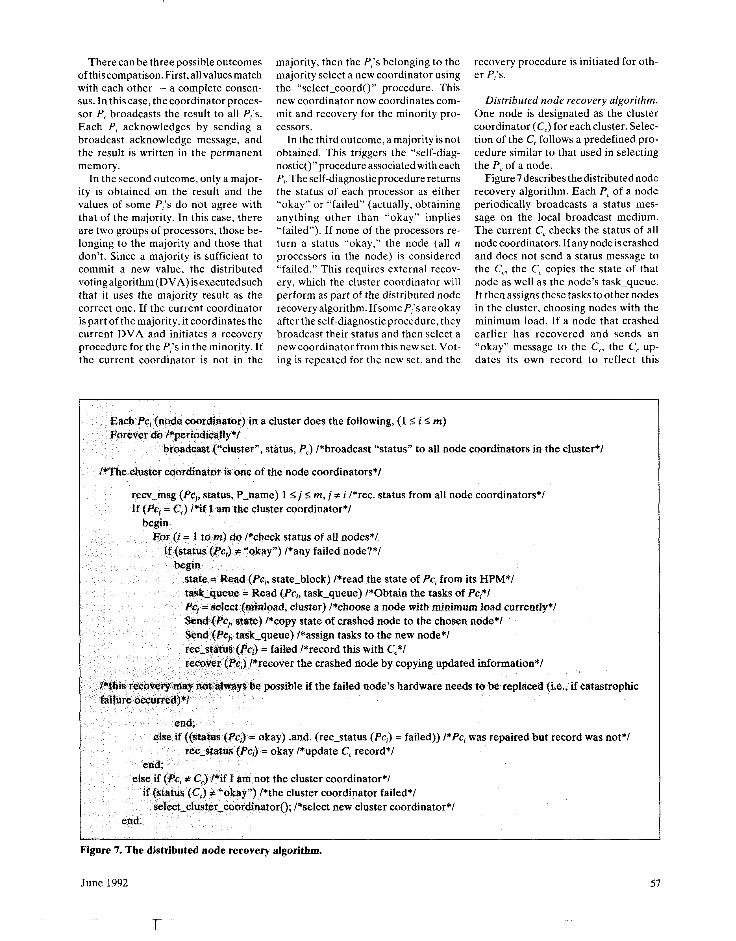
Distributed node recovery algorithm. One node is designated as the cluster coordinator (C,) for each cluster. Selec- tion of the C, follows a predefined pro- cedure similar to that used in selecting the P, of a node.
Figure 7 describes the distributed node recovery algorithm. Each PC of a node periodically broadcasts a status mes- sage on the local broadcast medium. The current C, checks the status of all node coordinators. If any node is crashed and does not send a status message to the C,, the C, copies the state of that node as well as the node’s task-queue. It then assigns these tasks to other nodes in the cluster, choosing nodes with the minimum load. If a node that crashed earlier has recovered and sends an “okay” message to the C,, the C, up- dates its own record to reflect this
Each PC, (node coordinator) in a cluster does the following, (15 i I m) Forever do /*periodically*/
broadcast (LLcluster”, ststus, PC) /*broadcast “status” to all node coordinators in the cluster*/
I&The cluster coordinator is one of the node coordinators*/
recv,msg (PC,, status, P-name) 1 5 j I rn, j # i /*rec. status from all node coordinators*/ If (PC, = C,) /*if I am the cluster coordinator*/
begin For (i = 1 tom) do /*check status of all nodes*/
If (status (PC,) f “okay”) /*any failed node?*/ begin
state = Read (PC,, state-block) /*read the state of Pci from its I-IPM*/ task-queue = Read (PC,, task-queue) /*Obtain the tasks of PC,*/ Pq = select (m&load, cluster) /*choose a node with minimum load currently*/ Send (PC+, state) /*copy state of crashed node to the chosen node*/ Send (PC, task-queue) /*assign tasks to the new node*/ ret,status (PcJ = failed /*record this with C,*/ recover (PC,) /*recover the crashed node by copying updated information*/
/*this recovery may not always be possible if the failed node’s hardware needs to be replaced (i.e., if catastrophic failure oecurred)*I
end; else if ((status (PC,) = okay) -and. (ret-status (PC,) = failed)) /*PC, was repaired but record was not*/
ret-status (Pci) = okay /*update C, record*/ end,
else if (PC, f C,> /*if I am not the cluster coordinator*/ if (status (C,) f “okay”) /*the cluster coordinator failed*/
select-ciuster-coordinatoro; /*select new cluster coordinator*/ end.
Figure 7. The distributed node recovery algorithm.
June 1992 57
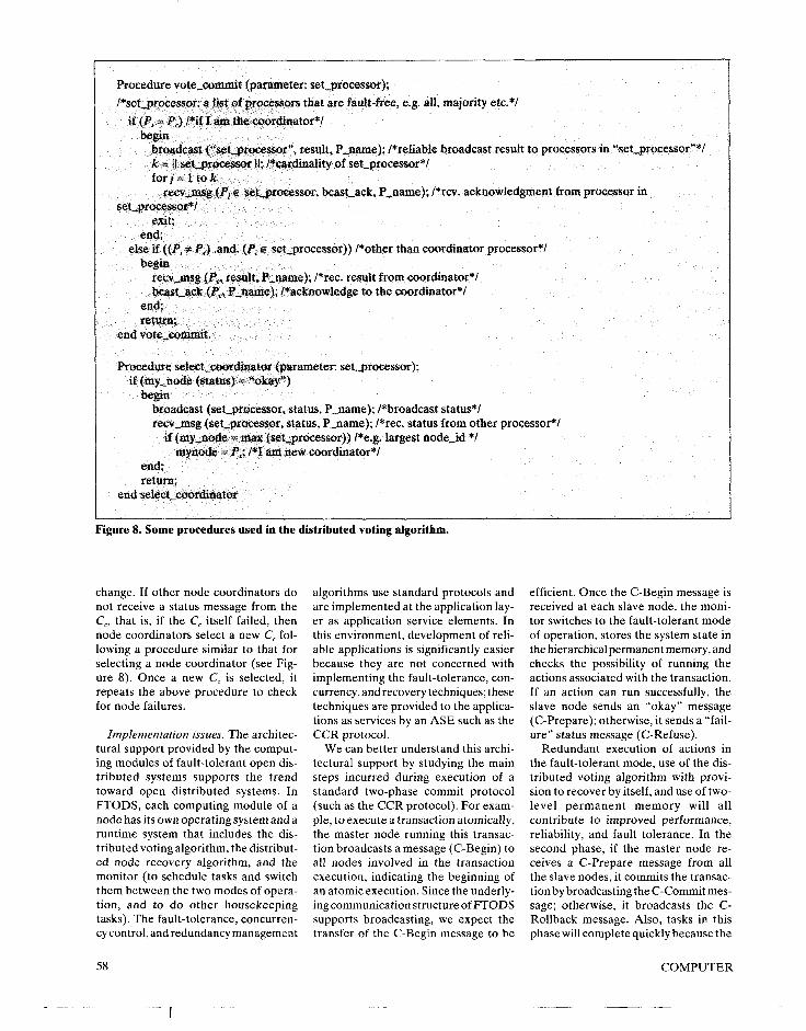
Procedure vote-commit (parameter: set-processor); /*set-processor: a list of processors that are fault-free, e.g. all, majority etc.*/
if (Pi = PC) /*if E am the coordinator*/ begin
broadcast (“set-processor”, result, P-name); /*reliable broadcast result to processors in “set-processor”*/ k = II set,processot II; I*cardinality of set-processor*/ forj=ltok
tecv,msg (Pr E setsrocessor, beast-ack, P-name); /*rev. acknowledgment from processor in set-processor*/
exit; end,
else if ((Pi r PJ -and. (Pi Q set-processor)) /*other than coordinator processor*/ begin
recv-msg (PC, result, P-name); /*rec. result from coordinator*/ beast-a& (PC, P-same); /*acknowledge to the coordinator*/
end; return;
end vote-commit.
Procedure select,mrdinator (parameter: set-processor); if (my-node (status) = “okay”)
begin broadcast (set-processor, status, P-name); /*broadcast status*/ recv-msg (set-processor, status, P-name); /*rec. status from other processor*/
if (my-node = max (set-processor)) /*e.g. largest node-id */ mynode = P,; /*I am new coordinator*/
end; return;
end select-coordinator
Figure 8. Some procedures used in the distributed voting algorithm.
change. If other node coordinators do not receive a status message from the C,, that is, if the C, itself failed, then node coordinators select a new C, fol- lowing a procedure similar to that for selecting a node coordinator (see Fig- ure 8). Once a new C, is selected, it repeats the above procedure to check for node failures.
Implementation issues. The architec- tural support provided by the comput- ing modules of fault-tolerant open dis- tributed systems supports the trend toward open distributed systems. In FTODS, each computing module of a node has its own operating system and a runtime system that includes the dis- tributed voting algorithm, the distribut- ed node recovery algorithm, and the monitor (to schedule tasks and switch them between the two modes of opera- tion, and to do other housekeeping tasks). The fault-tolerance, concurren- cy control, and redundancy management
algorithms use standard protocols and are implemented at the application lay- er as application service elements. In this environment, development of reli- able applications is significantly easier because they are not concerned with implementing the fault-tolerance, con- currency, and recovery techniques; these techniques are provided to the applica- tions as services by an ASE such as the CCR protocol.
We can better understand this archi- tectural support by studying the main steps incurred during execution of a standard two-phase commit protocol (such as the CCR protocol). For exam- ple, to execute a transaction atomically, the master node running this transac- tion broadcasts a message (C-Begin) to all nodes involved in the transaction execution, indicating the beginning of an atomic execution. Since the underly- ing communication structure of FTODS supports broadcasting, we expect the transfer of the C-Begin message to be
efficient. Once the C-Begin message is received at each slave node, the moni- tor switches to the fault-tolerant mode of operation, stores the system state in the hierarchical permanent memory, and checks the possibility of running the actions associated with the transaction. If an action can run successfully, the slave node sends an “okay” message (C-Prepare); otherwise, it sends a “fail- ure” status message (C-Refuse).
Redundant execution of actions in the fault-tolerant mode, use of the dis- tributed voting algorithm with provi- sion to recover by itself, and use of two- level permanent memory will all contribute to improved performance, reliability, and fault tolerance. In the second phase, if the master node re- ceives a C-Prepare message from all the slave nodes, it commits the transac- tion by broadcasting the C-Commit mes- sage; otherwise, it broadcasts the C- Rollback message. Also, tasks in this phase will complete quickly because the
58 COMPUTER
proposed architecture supports the broadcast capability and the rollback procedure.
We believe that providing architec- tural support at the node level and using standard protocols will significantly sim- plify the development of reliable dis- tributed applications, thereby making open distributed systems an attractive computing environment.
either case 1 or case 2, that is, f 5 N,, - 1. The expression for node reliability is obtained by computing the probability that at least one processor is operating successfully and is given by
N,-1
R, (N,) = C x Rbus c rNn-f (1 - r)’ f=O
(1)
Reliability analysis of FTODS
Node reliability. Assume that r rep- resents the reliability of each processor for a given period of time T. This reli- ability measure should take into account the failures caused by hardware as well as by software. Detailed Markovian methods can be used to predict the com- bined reliability measure that takes into consideration hardware faults and soft- ware errors - for example, design er- rors related to system overloads, over- flow/underflow of queues, etc. Assume also that a processor failure is exponen- tially distributed with a failure rate h. Let the number of processors in a node be N,, and f denote the number of faulty processors at a given time t. Depending on the number of faults, the distributed voting algorithm uses different proce- dures, as follows:
Case 1: Number of faultsf 5 rN,/21. In this case, a majority vote is attainable and the results obtained by the faulty processors can be masked out concur- rently by the coordinator processor with- out any extra delay.
Case 2: Number of faults rN,,/2i If I N, - 1. In this case, the majority of processors are faulty. However, there is at least one fault-free processor that can be identified by the diagnostic rou- tines. This processor ensures reliable execution of the tasks assigned to its node, but with a time penalty that re- sults from invoking the local diagnostic procedures.
Cuse3: Number of faults f = N,. In this case, all processors of a node are faulty; consequently, the node is in a failed state. The cluster coordinator invokes the distributed node recovery proce- dure to start a higher level recovery procedure, as previously described.
Node reliability can thus be defined as the probability of the node’s being in
is the binomial factor and is given by
N,,!
(Nn-f)!f!
In the above expression, the term rNn -1 denotes the probability of having N,, - f fault-free processors, while (1 - ry denotes the probability of having f faulty processors. The
NH ( 1 f
denotes the number of combinations in which there are f faulty processors cho- sen from N,, in a node. If the coverage factor is equal to one, the node can be viewed as a parallel redundant system with a redundancy level of N,, Node reliability can be evaluated as (1 - (1 - r)Nn).
Node reliability can be expressed with respect to time, if we assume that the processors fail according to an expo- nential distribution function with a fail- ure rate h. Consequently, node reliabil- ity at a given time t is given by
(exp-‘)Nn-f(l-exp-h’)f
(2)
Coverage C is an important parameter, and system reliability is extremely sen- sitive to its value. The coverage factor reflects the system’s ability to recover automatically from a fault once it oc- curs during normal operation. It de-
pends on the techniques used to detect, mask, locate, and repair faults, and to reconfigure and recover from the ef- fects of a failure. The methods used to predict coverage are therefore based on assumptions about the expected behav- ior of faults and how they are handled once they occur. Dugan and Trivedi5 presented several methods for predict- ing the coverage factor for different types of error behavior assumptions. In FTODS, a distributed voting algorithm is used to detect faulty processors and to mask their errors dynamically. There- fore, no recovery is needed as long as a majority vote can be obtained (case 1). Also, this algorithm uses a redundant system bus for comparing the results obtained by the processors. Since there is no single point of failure in the FTODS architecture and in the fault-tolerant algorithms, the coverage C is expected to be high; in this analysis it is assumed to be 1.
A node’s mean time to failure can also be evaluated from the above ex- pression (Equation 2) by integrating the node reliability expression:
MT-IF = j’,Y;Rn
To measure the reliability improvement as a result of introducing redundancy, we define a measure called the reliabil- ity improvement factor (RIF). This measure describes the relative increase in reliability for using N,, redundant pro- cessors to the maximal possible increase in reliability. Let’s assume that R,,(l) denotes the simplex reliability of a node. The maximal increase in reliability is obtained when R,(l) is increased to 1. The RIF for a given redundancy level (N,,) is computed as
RIF = R,(NJ-R,(l) l-R,(l)
Figure 9 shows the RIF obtained for three different levels of redundancy (3, 4, and 5). In this analysis, the reliability of a simplex bus is assumed to be a constant and equal to 0.95, because we are interested in studying the effect of redundancy level on node reliability. It is clear that more than 95 percent of the possible reliability improvement can be achieved when four processors are used. However, a triple modular re- dundancy configuration (level 3) could
June 1992 59
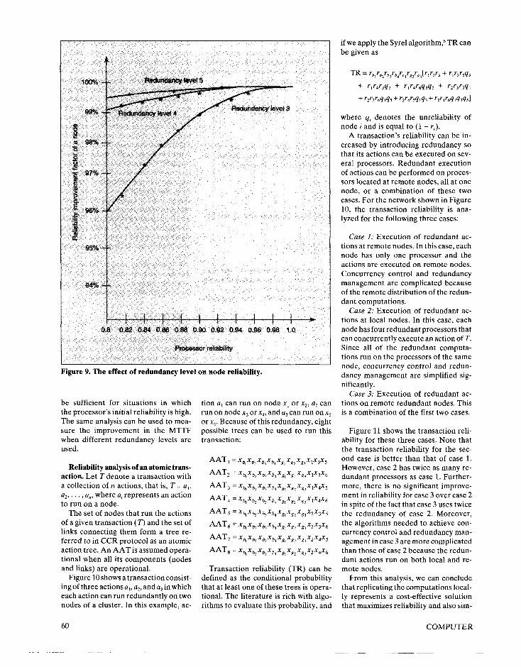
Figure 9. The effect of redundancy level on node reliability.
be sufficient for situations in which the processor’s initial reliability is high. The same analysis can be used to mea- sure the improvement in the MTTF when different redundancy levels are used.
Reliability analysis of an atomic trans- action. Let T denote a transaction with a collection of iz actions, that is, T = a,, a2,..., a,, where a, represents an action to run on a node.
The set of nodes that run the actions of a given transaction (T) and the set of links connecting them form a tree re- ferred to in CCR protocol as an atomic action tree. An AAT is assumed opera- tional when all its components (nodes and links) are operational.
Figure 10 shows a transaction consist- ing of three actions a,, a2, and a, in which each action can run redundantly on two nodes of a cluster. In this example, ac-
60
tion a, can run on node x, or xZr a, can run on node xj or x.,, and a3 can run on x5 or x6, Because of this redundancy, eight possible trees can be used to run this transaction:
AAT,=x 4 x x x x x 9 b, 4 gl gz x xxx 1 3 5 g3
AAT, =xb,Xb2Xb~Xb4Xg,Xg2Xg~X1X3X6
AAT,=x 4 x x x b4 x x b, b, 81 gz x xxx 1 4 5 gi
AAT4=xqXb~Xb,Xb~~g,~gZXg,X1x4X6
AAT,=x 4 x x x b4 x x bz 4 81 gz x xxx 2 3 5 a
~~~6=xqxb~Xb~Xba,Xg,XgzXg~X2X3X6
AAT,=x 4 x x x x x 9 b3 b4 g, gz x xxx 2 4 5 a
AAT,=x x x x x x x xxx k b, b, b4 gi gz 83 2 4 6
Transaction reliability (TR) can be defined as the conditional probability that at least one of these trees is opera- tional. The literature is rich with algo- rithms to evaluate this probability, and
if we apply the Syrel algorithm,6 TR can be given as
+ rlr4r5q3 + rlr4r6w5 + r2r3r59,
+ rzr3r6wh + r2r4r5w3 + r2r4r69d3951
where qi denotes the unreliability of node i and is equal to (1 - r,).
A transaction’s reliability can be in- creased by introducing redundancy so that its actions can be executed on sev- eral processors. Redundant execution of actions can be performed on proces- sors located at remote nodes, all at one node, or a combination of these two cases. For the network shown in Figure 10, the transaction reliability is ana- lyzed for the following three cases:
Case I: Execution of redundant ac- tions at remote nodes. In this case, each node has only one processor and the actions are executed on remote nodes. Concurrency control and redundancy management are complicated because of the remote distribution of the redun- dant computations.
Case 2: Execution of redundant ac- tions at local nodes. In this case, each node has four redundant processors that can concurrently execute an action of T. Since all of the redundant computa- tions run on the processors of the same node, concurrency control and redun- dancy management are simplified sig- nificantly.
Case 3: Execution of redundant ac- tions on remote redundant nodes. This is a combination of the first two cases.
Figure 11 shows the transaction reli- ability for these three cases. Note that the transaction reliability for the sec- ond case is better than that of case 1. However, case 2 has twice as many re- dundant processors as case 1. Further- more, there is no significant improve- ment in reliability for case 3 over case 2 in spite of the fact that case 3 uses twice the redundancy of case 2. Moreover, the algorithms needed to achieve con- currency control and redundancy man- agement in case 3 are more complicated than those of case 2 because the redun- dant actions run on both local and re- mote nodes.
From this analysis, we can conclude that replicating the computations local- ly represents a cost-effective solution that maximizes reliability and also sim-
COMPUTER
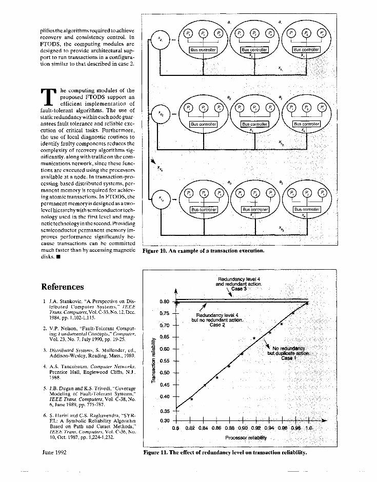
plifies the algorithms required to achieve recovery and consistency control. In FTODS, the computing modules are designed to provide architectural sup- port to run transactions in a configura- tion similar to that described in case 2.
T he computing modules of the proposed FTODS support an efficient implementation of
fault-tolerant algorithms. The use of static redundancy within each node guar- antees fault tolerance and reliable exe- cution of critical tasks. Furthermore, the use of local diagnostic routines to identify faulty components reduces the complexity of recovery algorithms sig- nificantly. alongwith trafficon the com- munications network, since these func- tions are executed using the processors available at a node. In transaction-pro- cessing-based distributed systems, per- manent memory is required for achiev- ing atomic transactions. In FTODS, the permanent memory is designed as a two- level hierarchy with semiconductor tech- nology used in the first level and mag- netic technology in the second. Providing semiconductor permanent memory im- proves performance significantly be- cause transactions can be committed much faster than by accessing magnetic disks. H
References 1. J.A. Stankovic, “A Perspective on Dis-
tributed Computer Systems,” IEEE Trans. Computers, Vol. C-33,No. 12, Dec. 1984, pp. 1,102-1,115.
2. V.P. Nelson, “Fault-Tolerant Comput- ing: Fundamental Concepts,” Computer, Vol. 23, No. 7, July 1990, pp. 19-25.
3. Distributed Systems, S. Mullender, ed., Addison-Wesley, Reading, Mass., 1989.
4. AS. Tanenbaum, Computer Networks, Prentice Hall, Englewood Cliffs, N.J., 1988.
5. J.B. Dugan and KS. Trivedi, “Coverage Modeling of Fault-Tolerant Systems,” IEEE Trans. Computers, Vol. C-38, No. 6, June 1989, pp. 775-787.
6. S. Hariri and C.S. Raghavendra, “SYR- EL: A Symbolic Reliability Algorithm Based on Path and Cutset Methods,” IEEE Trans. Computers, Vol. C-36, No. 10, Oct. 1987, pp. 1,224-1,232.
Figure 10. An example of a transaction execution.
0.80
0.75
0.70
f 0.65
$f 0.60
.j Q-55
f 0.50 I2 I- 0.45
0.40
0.35
0.30
. .--- andre
4
Rdwdancy level 4 drag; action.
t Redundancy level 4 ct no redundant action. - -
t
bl GaeeZ *
I I I I I I 1 I I
I I -,
0.8 0.82 0.84 0.86 0.88 0.90 0.@2 0.94 0.96 0.96 1.0
* / 4 No redundancy
but duplicate mtion. A--_ a
Processor rekbilii
June 1992 Figure 11. The effect of redundancy level on transaction reliability.
Salim Hariri is an assistant professor in the Electrical and Computer Engineering De- partment at Syracuse University, Syracuse, New York, and has worked and consulted at AT&T Bell Labs. His research focuses on computer architecture, distributed systems, fault-tolerant computing, and reliability and performance analysis of parallel and distrib- uted systems. He is the program chair for the First International Symposium on High-Per- formance Distributed Computing (HPDC l), scheduled for September 9-10.
Hariri received a BSEE, with distinction, from Damascus University, Damascus, Syr- ia, in 1977; an MSc from Ohio State Univer- sity, Columbus, Ohio, in 1982; and a PhD in computer engineering from the University of Southern California. He is a member of the IEEE, the IEEE Computer Society, and the ACM.
Alok Choudhary has been on the faculty of the Department of Electrical and Computer Engineering at Syracuse University since 1989. His research interests include parallel computer architectures, software develop- ment environments for parallel computers, and computer vision. He was a guest editor for the February 1992 issue of Computer on parallel processing for computer vision and image understanding.
Choudhary received his BE in electrical and electronics engineering from the Birla Institute of Technology and Science, Pilani, India. He obtained an MS from the Univer- sity of Massachusetts, Amherst, and a PhD from the University of Illinois, Urbana-Cham- paign, both in electrical and computer engi- neering. He is a member of the IEEE Com- puter Society and the ACM.
Behcet Sarikaya is on the faculty of Bilkent University, Ankara, Turkev. and was orevi-
-iI 1
ously with the Department of Computer Sci- ence and Operations Research at the Uni- versity of Montreal. His research interests include all aspects of conformance testing and high-speed networks. He has authored numerous published papers on communica- tion protocols and served on the program committees of three protocol conferences.
Sarikaya received a BSEE, with honors, and an MSc in computer science from the Middle East Technical University, Ankara, Turkey, in 1973 and 1976, respectively, and a PhD in computer science from McGill Uni- versity, Montreal, in 1984. He is a senior member of the IEEE, and a member of the IEEE Computer Society and the ACM.
Hariri and Choudhary can be contacted at Syracuse University, Department of Electrical and Computer Engineering, Syracuse, NY 13244. 4100; e-mail [email protected] or [email protected]. Sarikaya’s address is Bilkent University, Department of Computer Engineering and Information Sciences, Bilkent, Ankara 06533, Turkey; e-mail sarikaya%[email protected].
THIRD INTERNATIONAL WORKSHOP ON NETWORK AND OPERATING SYSTEM SUPPORT
FOR DIGITAL AUDIO AND VIDEO
November 12-13, 1992, San Diego, California
@ Sponsored by IEEE Communications and Computer Societies In cooperation with ACM SIGCOMM, SIGOIS, and SIGOPS 4b .
CALL FOR PAPERS Technological advances are revolutionizing computers and networks so as to support digital continuous video and audio, leading to new design spaces in computer systems and applications.
Program Committee: P. Venkat Rangan (Program Chair), Sid Ahuja, Gordon Blair, Rita Brennan, S. Christodoulakis, Flaviu Cristian, Domenico Ferrari, Riccardo Gusella, Ralf Herrtwich, Andy Hopper, Jim Kurose, Desai Narasimhalu, Duane Northcutt, Craig Partridge, Jon Rosenberg, Jean-Bernard Stefani, David Sincoskie, Daniel Swinehart, Stephen Casner, David Tennenhouse, and R. Popescu-Zeletin.
Relevant Areas: Multimedia Communication, Collaboration Management, Multimedia Storage Architectures, Media Synchronization, Multimedia Programming, Operating System Extensions for Multimedia, Admission Control and Real-Time Support, Multimedia Environments
Instructions for Submitting Papers: Authors are requested to submit a 500-2000 word position paper or extended abstract of a full paper (in raw, unformatted text) by electronic mail to [email protected]. Attendance will be limited to about 60 active researchers. For further information, contact the Program Chair at (619) 534-5419 or by e-mail to [email protected].
Proceedings will be published by Springer-Verlag, and best papers forwarded to selected journals for publication.
IMPORTANT DATES: Abstracts due: August 15, 1992, Acceptance notification: September 15, 1992, Final paper due: October 15, 1992