Embed Size (px)
Citation preview

International Journal of Computer and Information Sciences, VoL 14, No. 1, 1985
Architectural Support for Variable Addressing in Ada 1 - A Design Approach Prasenjit Biswas 2 and Subrata Dasgupta 3
Received July 1984; revised April 1985
In designing a language-directed machine architecture, the choice of the techni- que used in interpreting machine instructions has considerable influence on machine performance. Yet, there does not appear to exist any well established design method for choosing an interpretive mechanism; or for determining the hardware/firmware support for an efficient implementation of such a mechanism. The purpose of this paper is to propose such a design method, based on the use of an architecture description language. The specific architec- tural focus of the paper is the variable-addressing mechanism in Ada and the implications that such mechanisms have on the implementation of procedure CALL/RETURN and block ENTRY/EXIT functions; The analysis presented in this paper clearly establishes that either Dijkstra's mechanism or "local display method" is not suitable for adoption in designing architectural support for variable-addressing in Ada.
KEY WORDS: language-directed architecture; virtual and real transfer com- plexity; variable-addressing mechanisms proposed by Rohl, Tanenbaum, Dijkstra and the "local-display method".
1. INTRODUCTION
In designing an instruction set for a language-directed machine, usage statistics on various high-level language (HLL) constructs play an
1 Ada is a registered trademark of the United States Government Ada joint program office. 2 Department of Computer Science and Engineering, Southern Methodist University, Dallas,
Texas 75275. 3 Center for Advanced Computer Studies, University of Southwestern Louisiana, Lafayette,
Louisiana 70504.
51
0091-7036/85/0200-0051504.50/0 �9 1985 Plenum Publishing Corporation

52 Biswas and Dasgupta
obviously important role. (1-3~ Furthermore, the choice of the technique used in interpreting these instructions will have considerable influence on machine performance. Yet, there does not appear to exist any well established design method for choosing an interpretive mechanism or for determining the appropriate hardware/firmware support for an efficient implementation of such a mechenism, The purpose of this paper is to propose such a design method. The methodology is used in designing the architectural support for variable-addressing in Ada. In a more general sense it is also intended as a contribution to architecture design methodology. (4~
The architectural focus of this paper is the variable-addressing mechanism in programs written in block-structured language Ada and the implications that such mechanisms have on implementation of procedure CALL/RETURN and block ENTRY/EXIT functions. 4 It is well known that these are some of the most important and frequently used operations in block-structured HLL environment; hence they are highly appropriate candidates for architectural support through semantically "close" instruc- tions in a language directed machine. A one-to-one correspondence between such HLL functions and machine level instructions can lead to effective exploitation of the available processor/memory bandwidth. (2) This of course, implies that a single instruction like CALL (for example) would include in its semantics and its implementation a sequence of operations over and above those necessary for actual transfer of control.
The execution performance of the CALL/RETURN and ENTRY/EXIT instructions will clearly depend on the technique used to implement the variable-addressing mechanism. So the architect of a language-directed architecture is faced with the problem of choosing the most efficient implementation technique.
The results presented in this paper may be compared to De Prycker's work. (5/ De Prycker attempted to evaluate two different variable-address- ing methods implemented in existing architectures. We, on the other hand, concentrate primarily on the development of a method for designing the hardware/firmware support for the HLL procedure CALL/RETURN and block ENTRY/EXIT functions for a language-directed architecture.
Various techniques have been proposed by system designers for implementing the variable-addressing mechanism in block-structured languages. We will consider the following four techniques:
(a) The "classical" display mechanism as suggested by Dijkstra. (6)
(b) A modified display mechanism proposed by Rohl. (7~
4 Block structuring in Ada is similar to that of Algol with the important exception that Ada does not allow formal procedure parameters.

Architectural Support for Variable-Addressing in ADA 53
(c) A local display mechanism as implemented in the ICL 2900 Pascal compiler. (8/This was also implemented as part of a virtual architecture for Ada. (9)
(d) Tanenbaum's proposal/3~
We shall use the term architectural component to denote any part of an architecture that can be studied, analyzed and designed in reasonable isolation. For example, the architectural support provided for the HLL functions of procedure CALL and RETURN can be viewed as an architec- tural component. An examination of the execution 5 of such components within the framework of von Neumann style architectures reveals that the transfer operation is by far the predominating operation. Transfers can occur between:
(i) two memory locations;
(ii) a processor register and a memory location;
(iii) two processor registers.
Thus, it is quite reasonable to compare different implementation techniques in terms of the number of transfer operations to implement an architectural component in a given host processor. 6 If we assign appropriate weights for the different kinds of transfers and if the necessary statistics on program behavior are known, the average cost of execution of a particular implementation of an architectural component on a given host processor can be determined. This is, therefore, essentially a technique for analyzing the suitability of host processors for implementing given HLL functions. A similar study for two of the previously mentioned techniques for implementing variable-addressing mechanisms [(a) and (d)] was reported by De Prycker./5) However, as we shall show, the method we propose here should be regarded essentially as a design method rather than a technique for analysis.
To begin with, our only assumption concerning the underlying host processor organization is that it conforms to the von Neumann style. Thus, in the absence of any particular host structure it is necessary that we use an abstract way of describing architectural components and their implemen- tations. The architecture description language (ADL) S*A is used for this
s For convenience we use the phrase "execution of a component" to denote the collective sequence of events that would take place if a realization of the component were to be activated.
6 To avoid any terminological confusion we shall use the term "host" to denote any processor on which an architectural component supporting HLL functions are being implemented. We have borrowed this term, for obvious analogical reasons, from the terminology of microprogramming and emulation.
54 Biswas and Dasgupta
purpose. (4'1~ From an S*A description of an architectural component we derive two measures termed the Virtual Transfer Complexity (VTC) and the Average Virtual Transfer Complexity (AVTC). As explained in Sec- tion 3, the VTC measure is a design aid in that it indicates the minimum transfer complexity that could be achieved using a particular implemen- tation technique. Note that the VTC and AVTC measures as determined from an S*A description are independent of the characteristics of any par- ticular host structure. The AVTC measure, however, is dependent on the usage statistics obtained from the programming language environment under consideration.
The rest of the paper is organized as follows. In Section 2, we develop the notion of virtual transfer complexity. We also include some example VTCs computed for a few typical S*A statements. In Section 3, we review briefly, the relevant notions of maintenance and variable access in the run time representation of a typical Algol-like block-structured environment. Complete S*A descriptions of the procedure CALL/RETURN (CR) and block ENTRY/EXIT (BE) components for all four implementation techni- ques have been developed and are described in Ref. 12. For the sake of brevity, however, we include in this paper only two of these descriptions, viz., those of the techniques suggested by Rohl and Tanenbaum. In Sec- tion 4, we present the AVTs for the CR and BE components corresponding to each implementation technique.
In the remaining sections we derive a host processor organization from the S*A descriptions and evaluate the Real Transfer Complexity (RTC) of the components for this organization. A comparison of the AVTC and ARTC values indicate that the choice of implementation techniques could be restricted to those suggested by Rohl and Tanenbaum. It is, moreover, concluded that the choice between these two schemes depends critically on the relative frequency of procedures being declared at an intermediate (i.e., neither local nor global) lexical level with respect to the calling level.
2. V I R T U A L T R A N S F E R C O M P L E X I T Y
The ADL S*A has previously been described in several papers (see Refs. 10, 11, and 13). A complete definition of the language is available and has appeared in a book. (4) The use of S*A in describing architectures facilitates the design process in a number of ways:
(a) It makes it possible to describe the functioning and behavior of an architectural component at a level that is essentially indepen- dent of any particular hardware/firmware implementation of the component.

Architectural Support for Variable-Addressing in ADA 55
(b) The description helps identification of the specific statistics of the HLL environment upon which the performance of the architec- tural component depends. This, in turn, facilitates the collection of the appropriate usage statistics.
(c) The description clearly indicates the possible trade-offs between M and R measures u4) necessary for performance improvement. Furthermore, if all the architectural components of a language- directed architecture are considered together, the S*A descrip- tions of the components collectively provide a fairly complete picture of the hardware/firmware requirements of the underlying processor.
(d) Because S*A has been formally defined, it becomes possible to formally verify the correctness of an architectural design at a very early stage in the design process. ~3)
Given an S*A description of an architectural component, its virtual transfer complexity (VTC), when using a particular technique, is a measure of the number of transfers necessary for the "execution" of the component. In computing the VTC, all the variables are assumed to be available in the registers of a virtual processor. The array types are considered as register banks with the usual access mechanism, and a transfer through an ALU is view~ed as a register--register transfer between the input and output buffers of an ALU.
In the next section we will present the VTC and AVTC of the CALL/RETURN and ENTRY/EXIT components for all four of the variable-addressing mechanisms mentioned in Section 1. Before that, however, we illustrate the method of computing the VTC by taking some typical S*A statements.
Let us assume the following data type and data object declarations:
type M = seq [..] bit;
glovar A, B : array [..] of M;
glovar X, Y, P, Q : M
Here, we have defined a sequence data type named M; (global) variables X, Y, P, and Q are declared as instances of this type, while A and B are declared as arrays of elements of type M. The square brackets [..]. in the first two declarations simply represent the (unspecified) sizes of the sequence and array respectively.
Example 1. A[X-] := B[P + A[Q]]

56 Biswas and Dasgupta
The transfers are: from Q to the selection mechanism of A; from the selec- ted element of A to A L U 1 ; from P to ALU_2; transfer through the ALU; from ALU_0 to the selection mechanism of B; transfer from X to the selec- tion mechanism of A; and, finally, transfer from the selected element in B to the selected element in A. The VTC of this statement is 7.
Example 2.
while P = Q do S o d
Here S denotes the body of the while statement. If the VTC of S is w and assuming that S is iterated m times, the VTC of the while statement is mw+3(m+l ) ; the predicate is evaluated m + l times and in each evaluation three transfers are involved--from P to the comparator; from Q to the comparator; and a transfer through the comparator. The transfer involved in the branching operation is ignored--that is, we ignore the information transfer resulting from a transfer of control.
3. VARIABLE ADDRESSING TECHNIQUES
A program written in a block-structured language may be depicted as a tree which would highlight the nested structure of program blocks. (15'16) Each block would be associated with a level in the tree called its static lexical level.
Execution of a program may be viewed as a dynamic changing of lexical levels, hence, the lexical level of a block during program execution is termed its dynamic lexical level.
From a "static" point of view (i.e., the program as viewed at compile time) blocks and procedures are treated identically in that the body of a procedure is viewed as a block and is assigned a lexical level one higher than the level of declaration of the procedure identifier. Within a block, a variable is uniquely identified by the ordered pair
(lexical level, sequence number )
where "lexical level" denotes the static lexical level of the block in which the variable is declared and "sequence number" indicates the relative position of the declaration in the block.
A dynamic change in lexical levels occurs during a block invocation or a procedure call. However, the nature of the change in the two cases are quite different. The new (dynamic) level due to a block invocation is iden- tical to the static level of the invoked block whereas, calling a procedure
Architectural Support for Variable-Addressing in ADA 57
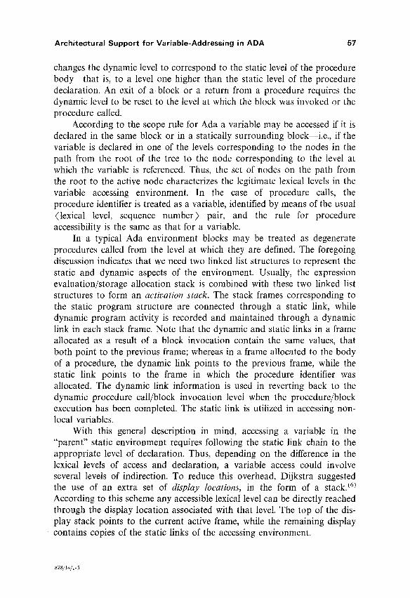
changes the dynamic level to correspond to the static level of the procedure body--that is, to a level one higher than the static level of the procedure declaration. An exit of a block or a return from a procedure requires the dynamic level to be reset to the level at which the block was invoked or the procedure called.
According to the scope rule for Ada a variable may be accessed if it is declared in the same block or in a statically surrounding block--i.e., if the variable is declared in one of the levels corresponding to the nodes in the path from the root of the tree to the node corresponding to the level at which the variable is referenced. Thus, the set of nodes on the path from the root to the active node characterizes the legitimate lexical levels in the variable accessing environment. In the case of procedure calls, the procedure identifier is treated as a variable, identified by means of the usual (lexical level, sequence number) pair, and the rule for procedure accessibility is the same as that for a variable.
In a typical Ada environment blocks may be treated as degenerate procedures called from the level at which they are defined. The foregoing discussion indicates that we need two linked list structures to represent the static and dynamic aspects of the environment. Usually, the expression evaluation/storage allocation stack is combined with these two linked list structures to form an activation stack. The stack frames corresponding to the static program structure are connected through a static link, while dynamic program activity is recorded and maintained through a dynamic link in each stack frame. Note that the dynamic and static links in a frame allocated as a result of a block invocation contain the same values, that both point to the previous frame; whereas in a frame allocated to the body of a procedure, the dynamic link points to the previous frame, while the static link points to the frame in which the procedure identifier was allocated. The dynamic link information is used in reverting back to the dynamic procedure call/block invocation level when the procedure/block execution has been completed. The static link is utilized in accessing non- local variables.
With this general description in mind, accessing a variable in the "parent" static environment requires following the static link chain to the appropriate level of declaration. Thus, depending on the difference in the lexical levels of access and declaration, a variable access could involve several levels of indirection. To reduce this overhead, Dijkstra suggested the use of an extra set of display locations, in the form of a stack. (6~ According to this scheme any accessible lexical level can be directly reached through the display location associated with that level. The top of the dis- play stack points to the current active frame, while the remaining display contains copies of the static links of the accessing environment.
828/14/1-5

58 Biswas and Dasgupta
A major problem with this now classical technique, is in rebuilding the display stack on return from a procedure; the number of locations to be reset is directly proportional to the lexical level difference between the call- ing level and that of the procedure declaration. A modification to this technique was suggested by Rohl. (7) He observed that in Dijkstra's scheme, there is a redundancy of information within the static links, the dynamic links, and the display. Rohl's modified version is described by the S*A mechanism M2 (Fig. 2) while Fig. la depicts the base of the corresponding stack frame. The static and dynamic links are replaced here by a single link that connects only the frames associated with the same lexical level. Thus, whenever we overwrite the contents of a display location (during a CALL or an ENTRY) the corresponding information is stored in the stack frame associated with that dynamic lexical level. So we can see that the display rebuilding overhead after returning from a procedure is independent of the lexical level difference between the calling level and the level of the
S p t r I
I F. l
Alloc./Eval. Area
Link
Ret. Address
Prey. Dis top
Prey. Frame Mark
DR (Dis top)
(a)
Fig. 1.
LP
FM
Alloc./Eval. Area
Stat. Link
Dyna. Link
Ret. Address
Prey. Frame Mark
Sptr
(b)
A view of the current stack frame just after execution of the procedures. (a) M2" Call; (b) M 4 . Call

Archi tectura l Suppor t fo r Var iable-Addressing in ADA 59
Proc RETURN ;
Sptr = Frame-mark ; (I) Frame-mark := Stack [sptr] ; (2)
/, Deallocation of frame ,/
Local := Display [Dis-top] ; (2)
Display [Dis-top] := Stack [Local-l] (5)
/* reinstated the content that was destroyed due
to call * /
Dis-top := Stack [Local - 3] ; [5)
Pctr := Stack [Local - 2] ; (5)
EndProo ;
Proc ENTRY ;
Stack [Sptr] := Frame-mark ; (2)
Frame-mark := Spit; (I) Sptr := Sptr * I ; (3)
Dis-top := Dis-top + 1 ; [3)
Stack [Sptr] := Display [Dis-Top] ; Sptr := $ptr + I ;
/, AS in call ,/
Display [Dis-top] := Sptr ; (3)
/* Display [Dis-top] points to present environment */
endProc ;
Proc EXIT ;
Sptr := Frame-mark ; (I)
Frame-mark := stack [sptr] ; (2)
Display [Dis-top] :=
Stack [Display [Dis-top] - I] ; (6)
/* restored the content overwritten due to
Block entry =/
Dis-top :- Dis-top - I ; (3)
EndProc ;
End Mech Mz ;
Fig. 2. S*A descriptions of CR and BE components of mechanism M2 (the numbers in parentheses indicate VTCs of the statements).

Mech M, ; /. TANENBAUM's METHOD */
type memword = seq [..] bit;
glovar mainmem: array [..] of memword;
syn stack = mainmem;
glovar sptr, Frame-mark, Pctr : memword;
glovar LP, GP : memword;
glovar Inst-reg : tuple
adr : tuple
Dlex: seq[..] bit;
Offset : seq [..] bit;
endtup
e n d t u p ;
: memword;
prlvar chain, Ptr : memword ;
Proc CALL;
Stack [Sptr] := Frame-mark ; (2)
Frame-mark := Sptr ; (I) Sptr:-Sptr + I ; (3)
Stack [Sptr] := Pctr ; (2) Sptr := Sptr + 1 ; (3)
Stack [Sptr] := LP ; (2) sptr := Sptr+ I ; (3)
/* Dynamic link stored */
If Inst-reg. Adr. Dlex = 'Global' (3)
Stack [Sptr] := GP ; (2) Ptr := GP; (I)
II Inst-reg. Adr. Dlex - 0 (3) Stack [sptr] := LP ; (2)
Ptr := LP; (I)
[] DO chain := Inst-reg.Adr. Dlex ; (I)
WHILE Chain--]= 0 (3 [m + I])
DO Ptr := Stack [Ptr - I] ; (4)
Chain := Chain - I ; (3)
OD
Stack [Sptr] := ptr ; (2) Sptr := Sptr § ] ; (3)
/* static link set ,/
OD /* m = lexical level difference between
the level of call and the level of declaration
of t h e p r o c e d u r e i d e n t i f i e r , when t h e p r o c e d u r e
i d e n t i f i e r i s an in termediate v a r i a b l e . , /
LP := Sptr; (I) /* New LP set */
Pctr :- S t a c k [ptr + Inst.reg. adr. offset] ; (5)
l n d P r o c ;

Architectural Support for Variable-Addressing in ADA 61
Proc RETURN ;
Sptr := Frame-mark ; (I)
Frame-mark := stack [sptr] : (21
Pctr := Stack [LP - 3] ; (5) /* ret. address
LP : Stack [LP - 2] ; (5) /* LP points to
Calling environment */
endProc;
P r o c ENTRY ;
Stack [sptr] : = Frame-mark ; (2)
Frame-mark := Sptr; (I) Sptr := Sptr * 1 ; (3)
Stack [sptr] := LP ; (21 sptr := sptr § 1 ; (3)
,/
Stack [sptr] := LP ; (2) sptr := sptr + I ; (3)
/, both links are stored, for uniformity in vat
access mem */
LP := Sptr; (I)
e n d P r o c ;
Proc EXIT ;
Sptr := Frame-mark ; (I)
Frame-mark := Stack [Sptr] ; (2)
LP := Stack [LP - I] ; (4)
e n d P r o c
end Mech H. ~.
Fig. 3. S*A descriptions of the CR and BE components of mechanism M4 (numbers in parentheses indicate VTCs of the
statements).
procedure declarat ion-- i t involves only the resetting of a single display location associated with the static lexical level of the procedure body.
Another technique for implementing variable-addressing through dis- play locations is the so-called "local display" method. (8"9) In this method, the display locations necessary to represent the current variable accessing environment are stored on the current frame of the activation stack. The current frame is deallocated on return from a procedure or on exit from a block. Thus, there is practically no oVerhead for rebuilding the display on return from a procedure.
62 Biswas and Dasgupta
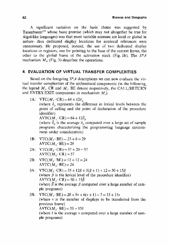
A significant variation on the basic theme was suggested by Tanenbaum (3) whose basic premise (which may not altogether be true for Algol-like languages) was that most variable accesses are local or global in nature--thus dedicated display locations for nontocal references were unnecessary. He proposed, instead, the use of two dedicated display locations or registers, one for pointing to the base of the current frame, the other to the global frame of the activation stack (Fig. lb). The S*A mechanism M 4 (Fig. 3) describes the operations.
4. E V A L U A T I O N OF V I R T U A L T R A N S F E R COMPLEXIT IES
Based on the foregoing S*A descriptions we can now evaluate the vir- tual transfer complexities of the archtectural components (in the following, the legend Ms. CR and Mi. BE denote respectively, the CALL/RETURN and ENTRY/EXIT components in mechanism Mi).
1A: V T C ( M l ' C R ) = 6 4 + 126p (where &p represents the difference in lexical levels between the point of calling and the point of declaration of the procedure identifier) AVTC(M1 �9 CR) = 64 + 128p (where 8p is the average 0p computed over a large set of sample programs characterizing the programming language environ- ment under consideration)
1B: VTC(M1-BE)=23 + 6 = 2 9 AVTC(M1 �9 BE) = 29
2A: VTC(M 2. CR) = 37 + 20 = 57 AVTC(M2" CR) = 57
2B: VTC(M 2. BE) = 12 + 12 = 24 AVTC(M 2 �9 BE) = 24
3A: V T C ( M 3 - C R ) = 3 5 + 12/?+3(/?+ 1)+ 1 2 = 5 0 + 15/? (where/? is the lexical level of the procedure identifier) AVTC(M3 -CR) = 50 + 15/~ (where/~ is the average/? computed over a large number of sam- ple programs)
3B: VTC(M3.BE)=20+9v+6(v+l)+7=33+15v (where v is the number of displays to be transferred from the previous frame) AVTC(M3 - BE) = 33 + 15~ (where f is the average v computed over a large number of sam- ple programs)

Architectural Support for Variable-Addressing in ADA 63
4A: V T C ( M 4 " C R ) = ff procedure identifier is a global variable
then (22 + 6) + 13 = 41 /f procedure identifier is a local variable at calling level
then (22 + 3 + 6) + 13 = 44 otherwise (22 + 3 + 3 + (106; + 13)) + 13 = 54 + 10~Sp AVTC(M 4 .CR) ---- 35 -k- r/pg(6) + r/p,(9) + t/pi(29 + 10S;)
where
tTpx= relative frequency of a procedure identifier being a global variable
~/pt = relative frequency of a procedure identifier being a local variable
r/p i = relative frequency of a procedure identifier being an intermediate variable
We assume that the relative frequencies are obtained by considering all the (static) procedure calls in a large number of sample programs characteriz- ing the programming language environment.
4B: V T C ( M 4. BE) = 24 AVTC(M4 �9 BE) = 24
4.1. Compar ison of the A V T C s
For purposes of comparison we use the following preliminary statistics on Algol 60 obtained by De Prycker(1):
Sp- - - - -2 ; /~---1; f~-2
Using these values we observe that:
AVTC(M1 ' CR) "~ 88; AVTC(M2 �9 CR) = 57; AVTC(M 3 �9 CR) - 65
Thus, as far as the CR component is concerned, M 2 �9 CR appears to be the most superior. Similarly, in the case of the BE component we obtain:
AVTC(M1 �9 BE) = 29; AVTC (M 2 �9 BE) = 24; AVTC(M 3 - BE) ,-~ 63
Again, M2" BE appears to be the most efficient. It is difficult to make an absolute comparison between M4" CR and
the other CR components as the statistics ~]pg, qpl, and ~/pi are unavailable. Nonetheless, it is possible to make an interesting observation when we compare AVTC(M2" C R ) - - t he best of the first three CR componen t s - -and AVTC(M4 �9 CR).

64 Biswas and Dasgupta
Let qpl + t/pg be denoted by t/lg. Then
AVTC(M4 �9 CR) - 35 + t/tg(7.5 ) + t/p~(29 + 20) = 35 + 7.5r/lg + 49t/pi
We know that AVTC(Ma' CR) = 57, and r/tg + r/pi = 1. Thus, we see that if the relative frequency of declaring a procedure at an intermediate level (t/p~) is greater than 0.35, then
AVTC(M4 �9 CR § M 4 �9 BE) > AVTC(M2 �9 CR § M2" BE)
(Note: AVTC(M 2 - BE) = AVTC(M4 �9 BE)) If we want to compare these implementation techniques for the pur-
pose of selecting a variable accessing mechanism for a block-structured environment, we need to take into account the VTCs of variable accesses. For the description of the four mechanisms it is obvious that the VTC of accessing a variable is the same for M~ and M2; this is less than the VTC of a variable access in M 3. The discussion on the average cost (per average program) of using any of these techniques is deferred to a later section (see Section 6) where we include the cost of variable access in the evaluation.
5. THE REAL T R A N S F E R C O M P L E X I T Y
The AVTCs indicate the best that the designer can extract from the implementation techniques. He is now faced with the problem of choosing one of the techniques for implementation on a real host architecture. Note that a choice based on AVTC computations might not be the best for a 'real' hardware/firmware realization unless we have an "ideal" range for mapping the domain of S*A constructs onto "real" hardware/firmware. (The following discussion is based on the use of a microprogram controlled processor; however, the conclusions reached would remain valid for an equivalent hardwired control scheme.)
The real transfer complexity (RTC) of an S*A statement is expressed as a matrix of three components, viz., the number of register-register trans- fers R(S1), the number of transfers through the ALU A(S1), and the num- ber of transfers across the processor-memory interface MP(S1), required for the execution of a statement $1, appearing in an S*A description. Thus:
RTC(S1)-- [R(S~) A(S~) MP(S1)]
We denote the RTC of a component X in mechanism Mt as RTC(Mt. X) where
RTC(M~ .X) = ~, RTC(Si) i

Architectural Support for Variable-Addressing in ADA 65
the summation taken over all the statements in the execution of the com- ponent M,-X. The Average RTC(ARTC) is calculated as before.
In the S*A description of the architectural components we have inten- tionally avoided any possible parallelisms among the various statements. Similarly, we assume that the microprogram control of the real host processor is of a purely vertical nature. We make these simplifying assumptions so that the fundamental issues in our design method are clearly visible. In passing, we note that the language S*A has adequate constructs to express parallelism. (4"~~ The mechanisms could easily be modified to include parallel operations, in which case the underlying firmware control (to be designed) would be changed to a horizontal scheme. The evaluation of the corresponding VTCs and RTCs would require very simple modifications.
Before we can compute the RTCs we need to propose an organization for the hardware/firmware complex that will support these components. The requirements that the host must meet to achieve a RTC measure reasonably close to the VTC measure can be directly extracted from the S*A descriptions.
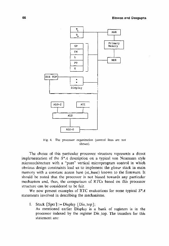
Rather than describe four different processor organizations for the four mechanisms, we adopt a basic yon Neumann style structure similar to Fuller's canonical processor (14) and indicate any special requirements needed for each mechanism. This organization is shown in Fig. 4. Though not clearly indicated in the diagram, it is assumed that any two of the registers can participate in a register-register transfer through a common bus.
The stack is assumed to be in main memory. The glovar Display is mapped onto a bank of registers, while the privar Dis_top is mapped onto a register that is used as a selector index for the register bank, Display. The glovar's Sptr, Pctr, and Frame_mark are mapped onto the processor registers SP, PC, and FM; Inst_reg is mapped onto IP (instruction register). The privar's local (in M 1 and M J as well as the glovar LP (in M4) are mapped onto the processor register L. The privar Ptr is mapped onto the register PT. The privar's Stat (in M1), Base (in M3) , and the gloval GP is mapped onto the register T1. At this point we do not specify which of the registers are user addressable and which ones are only used by the microprograms. Such a specification is quite straightforward if we restrict ourselves to a specific mechanism. In any case, the microcode can address any one of the registers. The register T2 is to be only used by the microcode. The register ACC serves as one of the inputs to the ALU. A L U 2 and ALU_0 are, respectively the second input and the output registers of the ALU. For any monadic ALU operation, the operand is expected to be in ACC.
66 Biswas and Dasgupta
I
I
FM
L
PT
G
Display
ALU 1
I ALU-O I
I Primary Memory
_&
Fig. 4. The processor organization (control lines are not shown).
The choice of this particular processor structure represents a direct implementation of the S*A description on a typical yon Neumann style microarchitecture with a "pure" vertical microprogram control in which obvious design constraints lead us to implement the glovar stack in main memory with a constant access base (st_base) known to the firmware. It should be noted that the processor is not biased towards any particular mechanism and, thus, the comparison of RTCs based on this processor structure can be considered to be fair.
We now present examples of RTC evaluations for some typical S*A statements involved in describing the mechanisms.
Stack [Sptr] :=Display [Dis_top]; As mentioned earlier Display is a bank of registers is in the processor indexed by the register D i s to p . The transfers for this statement are:

Architectural Support for Variable-Addressing in ADA 67
.
Display [Dis_top] --+ MDR; 2(R) Stack-base --+ ALU_2; (R) SP --+ ACC; (R) ADD; (A) A L U 0 ~ MAR; (R) WRITE; (M) The RTC of the statement is: [5R 1A 1M] Pctr :-- Stack [Display [Dis_top + Inst_reg. adr. offset] ] The Inst reg.adr, offset field of Inst_reg is known to the firmware and appropriate mask in known to the firmware for extracting the field. The transfers are: IR ~ ACC; (R) Mask (offset) --+ ALU_2; (R) AND; (A) ALU_0 --+ ALU2; (R) Dis top ~ ACC; (R) ADD; (A) Display [ALU_0] --+ ALU_2; 2 (R) Stack-base ACC; (R) ADD; (A) A L U 0 ~ MAR; (R) READ; (M) MDR ~ PC; (R)
(Note: The offset field was assumed to be right aligned; in cases of other fields e.g. Inst_reg. adr. Lex, the SHIFT operations required is counted as an average of one ALU transfer.) The RTC of the statement is: [9R3 A 1M] The RTCs for the other statements can be evaluated in a similar fashion.
The real transfer complexity (RTC) and the Average RTC(ARTC) of components discussed earlier are as follows:
la. RTC o f (MI"CR)= [87R27AllM] + (n+ 1)[2R1AOM] + n[10R3A1M]
= [(79 + 126p)R(24 + 46p)(10 + 6p)M] .F79, 24A 10M]
=[igp] [12R 4A IMJ
The ARTC (M1.CR) is obtained by replacing 6p by Sp in the previous expression.
lb. RTC(M~.BE) = [32R9A4M] =ARTC(M~-BE)
2a. RTC(M 2 �9 CR) = [70R22A9M] = ARTC(M2" CR)
2b. RTC(M2" BE) = [32R9A4M] = ARTC(M2' BE)
.r63R 22A 8M] 3a. RTC(M3"CR)= [1/~] [_13R 6A 2M
The ARTC(M3"CR) is obtained by replacing /~ by fl in the a previous expression.

68 Biswas and Dasgupta
.[38 e 13. 6~1 3b. RTC(M3"BE)= [1 v] [_15 R 7, 3~t
The expression for ARTC(M 3 - BE) is obtained by replacing v by f in the expression for RTC(M 3 �9 BE).
4a. RTC(M4'CR) = [57R17,7M] (if procedure identifier is a global variable)
or = [60R17A7M] (if procedure identifier is local to the calling block)
o r
~70R 20. 8M] =[1O'p] [10e 3. l x
(if procedure identifier is an intermediate variable)
I 4 9 R 16" 6 M I 8R 1A 1M
ARTC(M4" CR) = [l~pgqpt~pi ] I1R l , 1M
21+108p) R (4+38p) . (2+Sp)M
where ~lpg,~lpcrlpi, and ~; have their usual meanings as defined earlier.
4b. RTC(M 4 .BE) = [30R9A5~t ] = ARTC(~I 4"BE)
On comparing the ARTs of the CR and BE components of the three mechanisms M~, M 2, and M3, we come to the same conclusion, as in the previous section that is, in evaluating the average transfer cost of a program we need only consider the mechanisms M2 and m 4.
5.1. Overall Performance
As discussed earlier, in order to estimate the overall performance of an implementation technique for an "average" program it is essential to estimate the AVTC and ARTC of variable access. Furthermore, we need only compute these measures for the mechanisms M2 and M 4.
The variable access (VARAC) component of a mechanism should be composed of two separate procedures for Read and Write access. As the ARTC/AVTC of both subcomponents are identical, we will only describe the procedure for Read access (RVAR) for the two mechanisms. The declarative part of M2 and M 4 will not be repeated. We assume one more (system) glovar declaration for the variable Read_Value. In the description of the real processor architecture, Read_Value maps onto MDR.

Architectural Support for Variable-Addressing in ADA 69
The procedure RVAR for M 2 �9 VARAC is as follows:
Proc RVAR;/* for mech M2 */ Read_Value := Stack [Display [Inst_reg. Adr. Lexl + Inst_reg. Adr. Offset] (6)
endproc
Thus: AVTC(M2 - VARAC) = 6; ARTC(M2 �9 VARAC) = [11R5 A 1M] The Procedure RVAR for M 4 �9 VARAC is as follows: Proc R V A R / * for mech M4 */ I f Inst_reg. adr. Dlex -- 'Global' (3) ~ Read_value := Stack [ G P + offset]; (5) II Inst_reg. adr. Dlex = 0 (3) FI Read_value := Stack [ L P + o f f s e t l (5) JI DO Chain := Inst_reg. adr. Dlex; (1)
Ptr :=Stack [ L P - 11; (4) WHILE Chain r 0 (3 [p + 11 ) DO Ptr :=Stack [ P t r - 11; (4)
Chain := Chain - 1; (3) O D / * p = lex. level difference between the level of declaration and access of the intermediate vat. */fi';
endproc
The AVTC(M4 - VARAC) = 5 + r/g- 8 + t/l" 11 + t / i l l4 + 10~] , where ~g, t/l , and t/i are relative frequencies of global, local, and intermediate variable access respectively. 8~ = The mean lex.lev, difference between the level of declaration and level of access of an intermediate variable computed over a large number of sample programs.
ARTC(M4. VARAC) = [lr/gt/F/i I
4e 2A 0M
10R 3 A la,t
13e 3A 1M
(22 + 10~'v)R (5 + 38~)~ (2 + 8~)
For comparing the two mechanisms, as far as variable access is concerned, we use the preliminary statistics in Ref. 5. The statistics are:
r/g ~ 0 . 3 8 , ql-~ 0.28, t/i-~ 0.34, 8v-~ 1.0
On substituting, ARTC(M4. VARAC ) = [22.3 R 6.5A 1.7~t]
AVTC(M4 - VARAC) = 13.77

70 Biswas and Dasgupta
We use De Prycker's "program activity characterization" model ~1"5) to evaluate the average cost of using an implementation technique.
The average VTC of a block structured program using the technique proposed by Rohl is represented as:
where:
AVTC(P(M2)) = n b �9 24 + np. 57 q - r t v �9 6
nb = mean number of block ENTRY/EXIT's in a program
np = mean number of procedure CALL/RETURN's
n~ = mean number of variable accesses.
Similarly, for Tanenbaum's technique we obtain
AVTC(P(M2) ) = n b �9 24 + np(35 + 7.5 + 41.5qp;) + 13.77n~
Thus,
AVTC(P(M2)) < AVTC(P(M4))
provided that
24n b + 57np -k- 6n~ < 24n b + (42.5 + 41.5qpi) np + 13.77n~
or, considering n~/np to be a small positive quantity
~pi ~ 0.35
(Note: The preliminary statistics obtained in Ref. 1 from nine numerical programs for digital filtering and speech recognition is used for these evaluations.)
So we see that our earlier observation regarding the effectiveness of using either of these implementation techniques remains unaltered. It is, however, extremely difficult to predict the effectiveness of either of the techniques in terms of ARTC unless some reliable statistics are available r e g a r d i n g n p , rtv, rib, and ~/pi- We can only note that
ARTC(P(M4)) - ARTC(P(M2))
= np[(31,5rlpi- l l .5)R(9qpi-- 5)a(5t/pi-- 2)M]
+ nb[--2ROA1M] +nv[IO.2R--O.8AO,7M]

Architectural Support for Variable-Addressing in ADA 71
6. CONCLUSIONS
In this paper we have suggested a method for selecting the hardware/firmware support for the addressing mechanism in block-struc- tured HLL environments. This method can obviously be applied to other architectural components.
The original problem that prompted this particular investigation was the choice of one of these four addressing techniques as part of the design of a machine directed towards the programming language Ada. (17) In the absence of usage statistics for an Ada environment, available data on Algol 60 was used. We were surprised to discover the effectiveness of the relatively less known technique suggested by Rohl. It might be noted that Rohl's technique is suitable as long as formal procedure parameters are not taken into consideration. It can be considered almost as good as Tanen- baum's technique for the Ada environment as Ada does not allow formal procedure parameters. In the absence of any reliable statistics for r/pl we could not come to a definite conclusion regarding the choice between Tanenbaum's and Rohl's techniques. But considering some of the available statistics, e.g.,/~ = 1, ~ = 2, we may reasonably assume that the probability that ~pi ~ 0.5 is quite high. In such a case, Rohl's technique appears to be superior. The analysis clearly demonstrates that either Dijkstra's mechanism or the "local display" method is not suitable for adoption in designing the architectural support for variable-addressing of an architec- ture directed towards Ada.
REFERENCES
1. M. DePrycker, On the Development of a Measurement System for High Level Language Program Statistics, IEEE Trans. Comput., C-31(9) 883-891, (September 1982).
2. G. J. Myers, Advances in Computer Architecture, Wiley-Interscience, John Wiley & Sons, New York, (1982).
3. A. S. Tanenbaum, Implications of Structured Programming for Machine Architecture, Comm. ACM, 21(3) 237-245, (March 1978).
4. S. Dasgupta, The design and description of computer architectures, Willey-Interscience, John Wiley and Sons, New York (1984).
5. M. DePrycker, A Performance Analysis of the Implementation of Addressing Methods in Block Structured Languages, IEEE Trans. Comput., C-31(2) 155-163, (February 1982).
6. E. W. Dijkstra, Recursive programming, Numer. Math., 2, (1960). 7. J. S. Rohl, An Introduction to Compiler Writing, MacDonald/Elsevier, London, (1975). 8. M. J. Rees, et aL Pascal on an Advanced Architecture, Pascal-The Language and Its
Implementations, D. W. Barron (ed), John Wiley & Sons, New York, (1982). 9. O. Dommergaard, The Design of a Virtual Machine for Ada, Towards a Formal Descrip-
tion ofAda, D. Bjorner and O. N. Oest (eds), Springer-Verlag, Lecture Notes in Comp. Science, 98, Heidelberg, (1980).

72 Biswas and Dasgupta
10. S. Dasgupta, Computer design and description languages, Advances in Computers Vol. 21, M. C. Yovits (ed), Academic Press, New York, (1982).
11. S. Dasgupta and M. Otafsson, Towards .a Family of Languages for the Design and Implementation of Machine Architectures, Proc. 9th Annual Symp. on Comp. Architecture, IEEE Comp. Soc. Press, New York, (1982).
12. P. Biswas and S. Dasgupta, Architectural support for variable addressing in block-struc- tured languages, Tech Report 84-CSE-3, Southern Methodist University, (April 1984).
13. S. Dasgupta, On the Verification of Computer Architectures Using an Architecture Description Language, Proc. lOth Annual Symp. on Computer Architecture, IEEE Com. Soc. Press, Nex York, (1983).
14. S. H. Fuller and W. E. Burr, Measurement and Evaluation of Alternative Computer Architectures, IEEE Computer, (October 1977).
15. R. W. Doran, Computer Architecture: A Structured Approach, Academic Press, New York, (1979).
16. E. Horowitz, Fundamentals of Programming Languages, Computer Science Press, Rockville, Maryland, (1983).
17. P. Biswas, A capability architecture for Ada, IEEE Comp. Soc. Conf. on Ada Appl. and Env., St. Paul, Minnesota, (October 1984).
Printed in Belgium


![Exploring Architectural Details Through a Wearable ... · Rather different is the proposal by Thrin et al. [16]. Addressing the problem of recognizing multiple buildings in a large](https://img.pdfslide.net/doc/110x75/5cc3695988c993af3f8cb4e5/exploring-architectural-details-through-a-wearable-rather-different-is-the.jpg)