Embed Size (px)
Citation preview
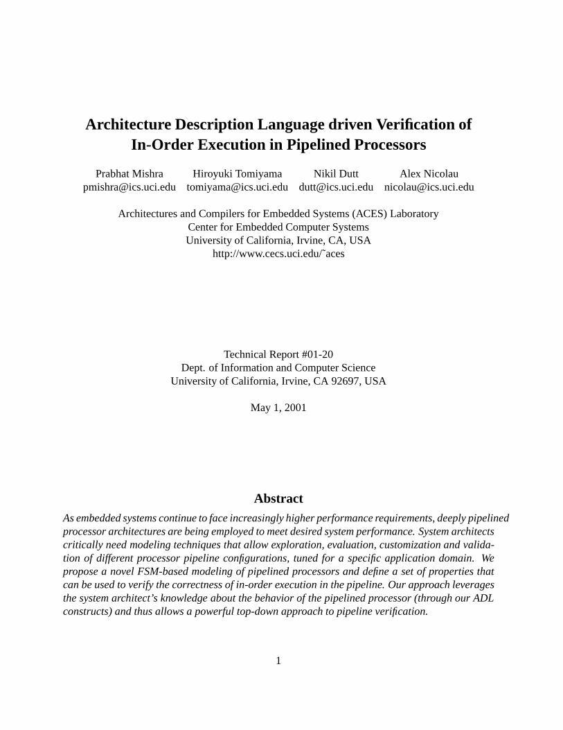
Architecture Description Language driven Verification ofIn-Order Execution in Pipelined Processors
Prabhat Mishra Hiroyuki Tomiyama Nikil Dutt Alex [email protected] [email protected] [email protected] [email protected]
Architectures and Compilers for Embedded Systems (ACES) LaboratoryCenter for Embedded Computer SystemsUniversity of California, Irvine, CA, USA
http://www.cecs.uci.edu/˜aces
Technical Report #01-20Dept. of Information and Computer Science
University of California, Irvine, CA 92697, USA
May 1, 2001
AbstractAs embedded systems continue to face increasingly higher performance requirements, deeply pipelinedprocessor architectures are being employed to meet desired system performance. System architectscritically need modeling techniques that allow exploration, evaluation, customization and valida-tion of different processor pipeline configurations, tuned for a specific application domain. Wepropose a novel FSM-based modeling of pipelined processors and define a set of properties thatcan be used to verify the correctness of in-order execution in the pipeline. Our approach leveragesthe system architect’s knowledge about the behavior of the pipelined processor (through our ADLconstructs) and thus allows a powerful top-down approach to pipeline verification.
1
Contents
1 Introduction 3
2 Related Work 3
3 Our Approach 4
4 Modeling of Processor Pipelines 44.1 Processor Pipeline Description in ADL . . . .. . . . . . . . . . . . . . . . . . . . 44.2 FSM Model of Processor Pipelines . . . . . .. . . . . . . . . . . . . . . . . . . . 7
5 Verification of In-Order Execution 105.1 Determinism . . . . . . . . . . . . . . . . . . . . . . . . . . . . . . . . . . . . . 105.2 In-Order Execution . . . . . . . . . . . . . . . . . . . . . . . . . . . . . . . . . . 115.3 Finiteness . . . . . . . . . . . . . . . . . . . . . . . . . . . . . . . . . . . . . . . 13
6 Property Verification Framework 136.1 EXPRESSION ADL . . . . . . . . . . . . . . . . . . . . . . . . . . . . . . . . . 136.2 Graph Model . . . . . . . . . . . . . . . . . . . . . . . . . . . . . . . . . . . . . 156.3 FSM Model . . . . . . . . . . . . . . . . . . . . . . . . . . . . . . . . . . . . . . 156.4 Verify Properties . . . . . . . . . . . . . . . . . . . . . . . . . . . . . . . . . . . 16
7 A Case Study 17
8 Summary 21
9 Acknowledgments 21
List of Figures
1 The Flow in our approach . . . . . . . . . . . . . . . . . . . . . . . . . . . . . . 52 A fragment of the processor pipeline . . . . .. . . . . . . . . . . . . . . . . . . . 6
3 FSM model of the fragment in Figure 2 . . .. . . . . . . . . . . . . . . . . . . . 7
4 Property Verification Framework . . . . . . . . . . . . . . . . . . . . . . . . . . . 145 The DLX Processor . . . . . .. . . . . . . . . . . . . . . . . . . . . . . . . . . 18
2
1 Introduction
Embedded systems present a tremendous opportunity to customize the designs by exploiting theapplication behavior using customizable processor cores and a variety of memory configurationsalong with different compiler techniques to meet the diverse requirements, viz., better performance,low power, smaller area, higher code density etc. However, shrinking time-to-market, coupledwith increasingly short product lifetimes create a critical need to rapidly explore and evaluatecandidate SOC architectures. To enable rapid design space exploration there is a need for rapidsoftware toolkit generation. Recent work on language-driven Design Space Exploration (DSE)([1], [3], [4], [5], [6], [8], [15], [17], [19]), uses Architectural Description Languages (ADL) tocapture the processor architecture, generate automatically a software toolkit (including compiler,simulator, assembler) for that processor, and provide feedback to the designer on the quality ofthe architecture. It is important to verify the ADL description of the architecture to ensure thecorrectness of the software toolkit. The benefits of verification are two-fold. One, specificationof architectures in ADLs is a tedious and error-prone process and verification techniques can beused to check for correctness of specification. Second, changes made to the processor during DSEmay result in incorrect execution of the system and verification techniques can be used to ensurecorrectness of the architecture.
Many existing approaches ([12], [10], [20]) employ a bottom-up approach to pipeline verifica-tion/validation, where the functionality of an existing pipelined processor is, in essence, reverse-engineered from its RT-level implementation. Our approach leverages the system architects knowl-edge about the behavior of the pipelined processor (through our ADL constructs) and thus allowsa powerful top-down approach to pipeline validation and verification, using behavioral knowledgeof the pipelined architecture.
The rest of the paper is organized as follows. Section 2 presents related work addressing ver-ification of pipelined processors. Section 3 outlines our approach and the overall flow of ourenvironment. Section 4 presents our FSM based modeling of pipelined processors. Section 5 pro-poses our verification technique followed by a case study in Section 7. Section 8 concludes thepaper.
2 Related Work
So far formal or semi-formal verification of pipelined processors has been studied in a number ofliterature. For example, Burch and Dill presented a technique for formally verifying pipelined pro-cessor control circuitry [2]. Their technique verifies the correctness of the implementation model ofa pipelined processor against its Instruction-Set Architecture (ISA) model based on quantifier-freelogic of equality with uninterpreted functions. The technique has been extended to handle morecomplex pipelined architectures by several researchers [16, 21]. Huggins and Campenhout verifiedthe ARM2 pipelined processor using Abstract State Machine [9]. In [14], Levitt and Olukotun pre-sented a verification technique, called unpipelining, which repeatedly merges last two pipe stagesinto one single stage, resulting in a sequential version of the processor. Hauke and Hayes proposeda technique, called reverse engineering, which extracts the ISA model of a pipelined processor
3
from its implementation model [10]. Then, the extracted ISA is compared with a user-specifiedISA. All the above techniques tried to formally verify the implementation of pipelined processorsby comparing the pipelined implementation with its sequential (ISA) specification model, or byderiving the sequential model from the implementation. On the other hand, in our verification ap-proach, we are trying to define a set of properties which have to be satisfied for the correct pipelinebehavior, and verify the correctness of pipelined processors by testing whether the properties aremet using a Finite State Machine (FSM)-based modeling.
Iwashita et al. [13] and Ur and Yadin [20] presented pipelined processor modelings based onFSM. They used their FSM to automatically generate test programs for simulation-based valida-tion of the processors. On the other hand, this paper addresses formal verification of pipelinedprocessors without simulation.
Tomiyama et al. [18] presented FSM based modeling of pipelined processors with in-orderexecution and closest to our approach. Their model can handle only simple processors with straightpipeline. On the other hand, our model can handle processors with fragmented pipelines andmulticycle units. They defined three properties that need to be met for correct in-order execution.However, the paper did not describe how to apply these properties for verifying the correctness.In our verification approach, we present an automatic property checking framework driven by anADL.
3 Our Approach
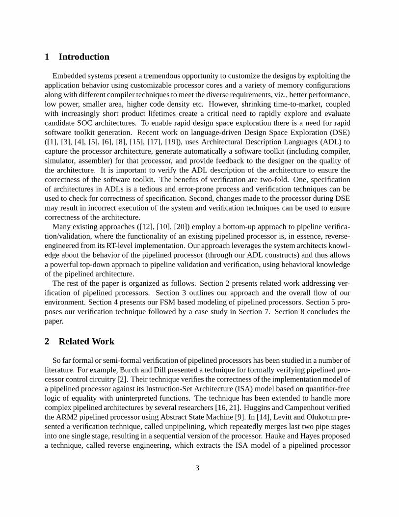
Figure 1 shows the flow in our approach. In our IP library based exploration and verification sce-nario, the designer starts by specifying the processor and memory subsystem description in ADL.The FSM model of the pipelined processor description is automatically generated from the ADLdescription. We have defined properties to ensure that the ADL description of the architecture iswell-formed. Our automatic property checking framework determines if the property is satisfied ornot. In case of failure, it generates the traces so that the designer can modify the ADL specificationof the architecture. If the verification is successful, the software toolkit (including compiler andsimulator) can be generated for design space exploration.
4 Modeling of Processor Pipelines
In this section we describe how we model the pipeline in FSM from the ADL description of theprocessor. We first explain the information captured in the ADL necessary for the FSM modeling,then we present the FSM model of the processor pipelines using the information captured in theADL.
4.1 Processor Pipeline Description in ADL
An ADL that contains a description of both the behavior and the structure of the processor canbe used in our verification and exploration framework. The advantage of using mixed-level ADLsis that it becomes possible to verify the structure against the behavior (e.g., verification of the
4
Processor IP Library
ADL Specification
Verified
Failed
Obj
Feedback
Compiler Simulator
Processor Core
FSM
Appl
Properties
Figure 1. The Flow in our approach
pipeline structure against the expected behavior). We first describe the structure and behavior ofthe processor captured in ADL, then we describe how to capture the conditions for stalling, normalflow and nop insertion for each functional unit.
Structure and Behavior of the Processor
The structure contains functional and storage units connected by pipeline and data transfer paths.A path from a functional unit to storage or from a storage to a functional unit is called a datatransfer path. A path from the first unit (e.g, PC Unit or Fetch Unit in most of the processors)to the last unit (e.g., WriteBack Unit or Completion Unit in most of the processors) consisting offunctional units and pipeline edges is called a pipeline path. A pipeline edge specifies the orderingof functional units comprising the pipeline stages. Intuitively, a pipeline path denotes an executionflow in the pipeline taken by an operation. Informally, a pipeline edge transfers instruction anddata from parent unit to child unit using pipeline latch (referred in this paper as pipeline register orinstruction register). Each unit may have several attributes e.g.,capacity, timing etc. The capacitydenotes the maximum number of operations which the unit can handle in a cycle (e.g., certaindecode unit in VLIW processor can issuemoperations per cycle to themparallel execution units),while the timing denotes the number of cycles taken by the unit (e.g., certain multicycle unit takesn cycles whereas single-cycle unit takes 1 cycle).
The behavior of a processor is a set of operations that can be executed on it. Each operation inturn consists of a set of fields (e.g., opcode, arguments etc.) that specify, at an abstract level, theexecution semantics of the operation.
The mapping between structure and behavior captures, for each functional or storage unit, theset of operations supported by the unit.
5
Modeling Conditions in ADL
Along with the structure, behavior and their mapping information already available in the ADLdescription, designers need to capture in ADL the conditions for stalling, normal flow and nopinsertion for each functional unit.
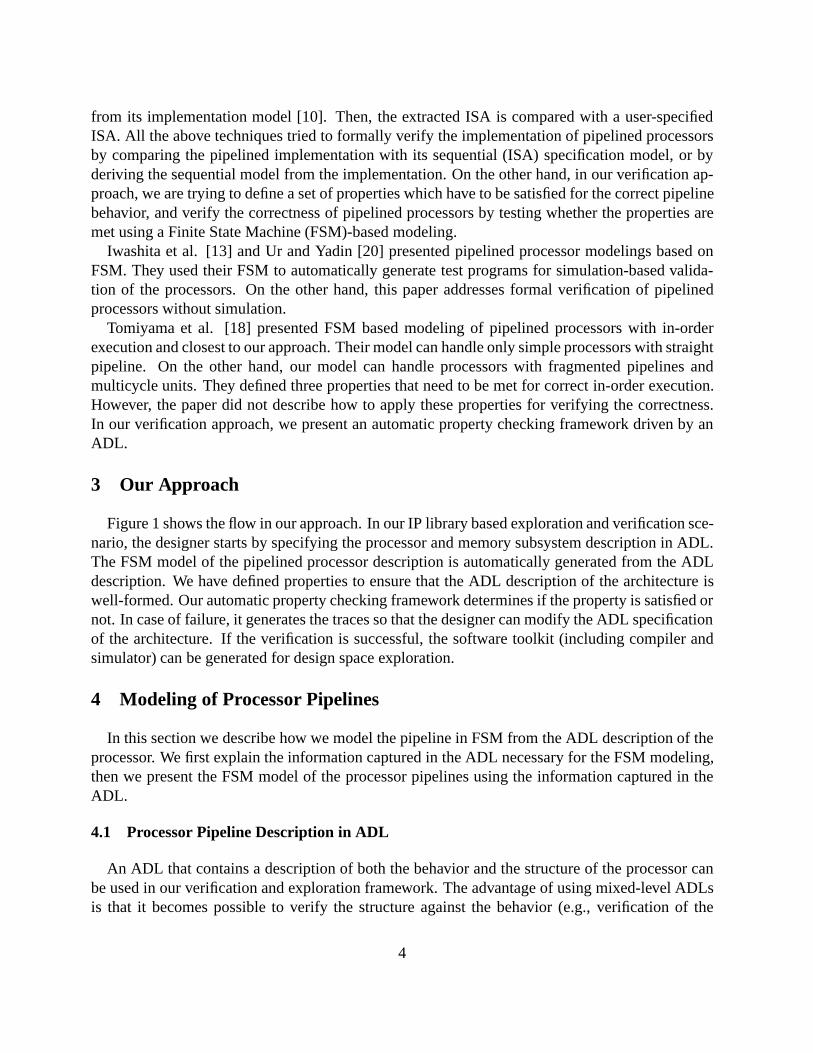
A unit can be stalled due to signals external to the processor or due to contributions arising insidethe processor. For example, the external signal that can stall the fetch unit isICacheMiss; internalcondition for stalling of fetch unit can be due to decode stall. For units, with multiple childrenthe stalling conditions due to internal contribution may differ. For example, the unitUNITi�1; j
in Figure 2 withq children can be stalled when anyone of its children are stalled, or when someof its children are stalled (designers identifies the specific ones), or when all of its children arestalled; or when none of its children are stalled. During description, designer chooses from the set(ANY, SOME, ALL, NONE) for internal contribution along with any external signals to specifystall condition for each unit.
Stage i−2
Stage i−1
Stage i
UNITi−2, r+1
UNITUNIT
UNIT
IR i−1, r+2 IR i−1, r+p
UNITi−2, r+pi−2, r+2
UNITi−1, j
UNIT
IR i+1, s+1 IR i+1, s+2 IR i+1, s+q
IR i,j
IR i−1, r+1 . . . . .
. . . . .
i, s+1 i, s+2 i, s+q
Figure 2. A fragment of the processor pipeline
A unit can be in normal flow if it can receive instruction from its parent unit and can send to itschild latch. For units with multiple parents and multiple children the normal flow condition maydiffer. For example, the unitUNITi�1; j in Figure 2 withp parent units andq children units can flownormally depending on several combination of states among its parent units and child units. Forexample, one of its parents is not stalled and one of its children is not stalled, or one of its parentsis not stalled and all of its children are not stalled (e.g., decode stage in a VLIW processor withno reservation station) etc. During specification the designer chooses from the set (ANY, SOME,ALL, NONE) the contributions from the parents and children to specify the normal flow conditionfor each unit.
Typically, a unit performs nop insertion when it does not receive any instruction from the parent(or busy computing in case of multicycle unit) and its child is not stalled. For units with multi-ple parents and multiple children the nop insertion condition may differ. For example, the unit
6
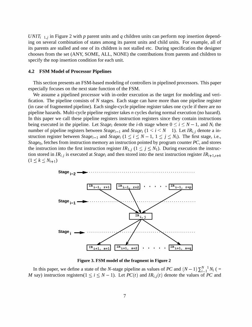
UNITi�1; j in Figure 2 withp parent units andq children units can perform nop insertion depend-ing on several combination of states among its parent units and child units. For example, all ofits parents are stalled and one of its children is not stalled etc. During specification the designerchooses from the set (ANY, SOME, ALL, NONE) the contributions from parents and children tospecify the nop insertion condition for each unit.
4.2 FSM Model of Processor Pipelines
This section presents an FSM-based modeling of controllers in pipelined processors. This paperespecially focuses on the next state function of the FSM.
We assume a pipelined processor with in-order execution as the target for modeling and veri-fication. The pipeline consists ofN stages. Each stage can have more than one pipeline register(in case of fragmented pipeline). Each single-cycle pipeline register takes one cycle if there are nopipeline hazards. Multi-cycle pipeline register takesn cycles during normal execution (no hazard).In this paper we call these pipeline registers instruction registers since they contain instructionsbeing executed in the pipeline. LetStagei denote thei-th stage where 0� i � N�1, andNi thenumber of pipeline registers betweenStagei�1 andStagei (1� i � N�1). Let IRi; j denote a in-struction register betweenStagei�1 andStagei (1� i � N�1, 1� j � Ni). The first stage, i.e.,Stage0, fetches from instruction memory an instruction pointed by program counterPC, and storesthe instruction into the first instruction registerIR1; j (1� j � N1). During execution the instruc-tion stored inIRi; j is executed atStagei and then stored into the next instruction registerIRi+1;s+k
(1� k� Ni+1)
Stage i−2
Stage i−1
Stage i
IR i−1, r+2 IR i−1, r+p
IR i+1, s+1 IR i+1, s+2 IR i+1, s+q
IR i,j
IR i−1, r+1 . . . . .
. . . . .
.....................................................
.....................................................
.....................................................
Figure 3. FSM model of the fragment in Figure 2
In this paper, we define a state of theN-stage pipeline as values ofPC and(N�1)∑N�1i=1 Ni ( =
M say) instruction registers(1� i � N�1). Let PC(t) and IRi; j(t) denote the values ofPC and
7
IRi; j at timet, respectively. Then, the state of the pipeline at timet is defined as
S(t) =< PC(t); IR1;1(t); � � �; IRN�1;NN�1(t)> (1)
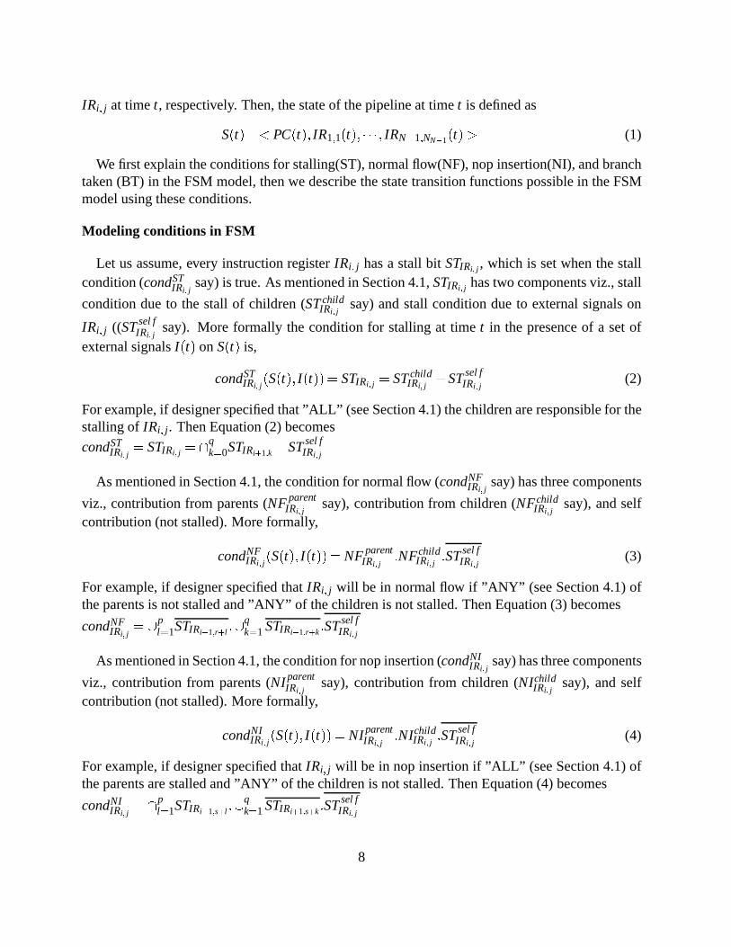
We first explain the conditions for stalling(ST), normal flow(NF), nop insertion(NI), and branchtaken (BT) in the FSM model, then we describe the state transition functions possible in the FSMmodel using these conditions.
Modeling conditions in FSM
Let us assume, every instruction registerIRi; j has a stall bitSTIRi; j , which is set when the stallcondition (condST
IRi; jsay) is true. As mentioned in Section 4.1,STIRi; j has two components viz., stall
condition due to the stall of children (STchildIRi; j
say) and stall condition due to external signals on
IRi; j ((STsel fIRi; j
say). More formally the condition for stalling at timet in the presence of a set ofexternal signalsI(t) on S(t) is,
condSTIRi; j
(S(t); I(t))= STIRi; j = STchildIRi; j
+STsel fIRi; j
(2)
For example, if designer specified that ”ALL” (see Section 4.1) the children are responsible for thestalling ofIRi; j . Then Equation (2) becomes
condSTIRi; j
= STIRi; j = \qk=0STIRi+1;k +STsel f
IRi; j
As mentioned in Section 4.1, the condition for normal flow (condNFIRi; j
say) has three components
viz., contribution from parents (NFparentIRi; j
say), contribution from children (NFchildIRi; j
say), and selfcontribution (not stalled). More formally,
condNFIRi; j
(S(t); I(t))= NFparentIRi; j
:NFchildIRi; j
:STsel fIRi; j
(3)
For example, if designer specified thatIRi; j will be in normal flow if ”ANY” (see Section 4.1) ofthe parents is not stalled and ”ANY” of the children is not stalled. Then Equation (3) becomes
condNFIRi; j
= [pl=1STIRi�1;r+l :[
qk=1 STIRi+1;r+k:STsel f
IRi; j
As mentioned in Section 4.1, the condition for nop insertion (condNIIRi; j
say) has three components
viz., contribution from parents (NIparentIRi; j
say), contribution from children (NIchildIRi; j
say), and selfcontribution (not stalled). More formally,
condNIIRi; j
(S(t); I(t))= NIparentIRi; j
:NIchildIRi; j
:STsel fIRi; j
(4)
For example, if designer specified thatIRi; j will be in nop insertion if ”ALL” (see Section 4.1) ofthe parents are stalled and ”ANY” of the children is not stalled. Then Equation (4) becomes
condNIIRi; j
= \pl=1STIRi�1;s+l :[
qk=1 STIRi+1;s+k:STsel f
IRi; j
8
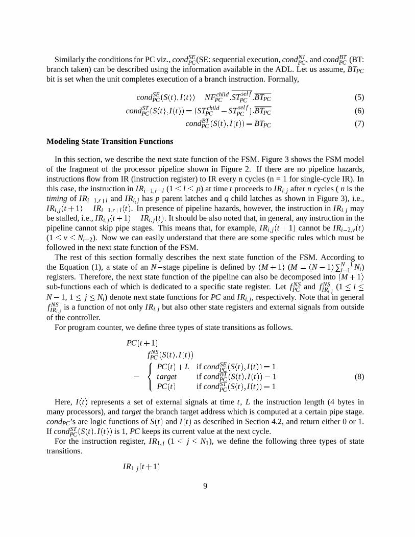
Similarly the conditions for PC viz.,condSEPC(SE: sequential execution,condNI
PC, andcondBTPC (BT:
branch taken) can be described using the information available in the ADL. Let us assume,BTPC
bit is set when the unit completes execution of a branch instruction. Formally,
condSEPC(S(t); I(t))= NFchild
PC :STsel fPC :BTPC (5)
condSTPC(S(t); I(t))= (STchild
PC +STsel fPC ):BTPC (6)
condBTPC(S(t); I(t))= BTPC (7)
Modeling State Transition Functions
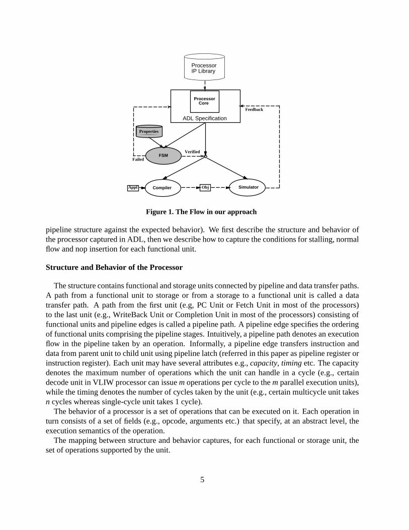
In this section, we describe the next state function of the FSM. Figure 3 shows the FSM modelof the fragment of the processor pipeline shown in Figure 2. If there are no pipeline hazards,instructions flow from IR (instruction register) to IR every n cycles (n = 1 for single-cycle IR). Inthis case, the instruction inIRi�1;r+l (1� l � p) at timet proceeds toIRi; j aftern cycles (n is thetiming of IRi�1;r+l and IRi; j hasp parent latches andq child latches as shown in Figure 3), i.e.,IRi; j(t+1) = IRi�1;r+l(t). In presence of pipeline hazards, however, the instruction inIRi; j maybe stalled, i.e.,IRi; j(t+1) = IRi; j(t). It should be also noted that, in general, any instruction in thepipeline cannot skip pipe stages. This means that, for example,IRi; j(t +1) cannot beIRi�2;v(t)(1� v� Ni�2). Now we can easily understand that there are some specific rules which must befollowed in the next state function of the FSM.
The rest of this section formally describes the next state function of the FSM. According tothe Equation (1), a state of anN�stage pipeline is defined by(M + 1) (M = (N� 1)∑N�1
i=1 Ni)registers. Therefore, the next state function of the pipeline can also be decomposed into(M+1)sub-functions each of which is dedicated to a specific state register. Letf NS
PC and f NSIRi; j
(1� i �N�1, 1� j � Ni) denote next state functions forPC andIRi; j , respectively. Note that in generalf NSIRi; j
is a function of not onlyIRi; j but also other state registers and external signals from outsideof the controller.
For program counter, we define three types of state transitions as follows.
PC(t+1)
= f NSPC(S(t); I(t))
=
8<:
PC(t)+L if condSEPC(S(t); I(t))= 1
target if condBTPC(S(t); I(t))= 1
PC(t) if condSTPC(S(t); I(t))= 1
(8)
Here, I(t) represents a set of external signals at timet, L the instruction length (4 bytes inmany processors), andtarget the branch target address which is computed at a certain pipe stage.condPC’s are logic functions ofS(t) andI(t) as described in Section 4.2, and return either 0 or 1.If condST
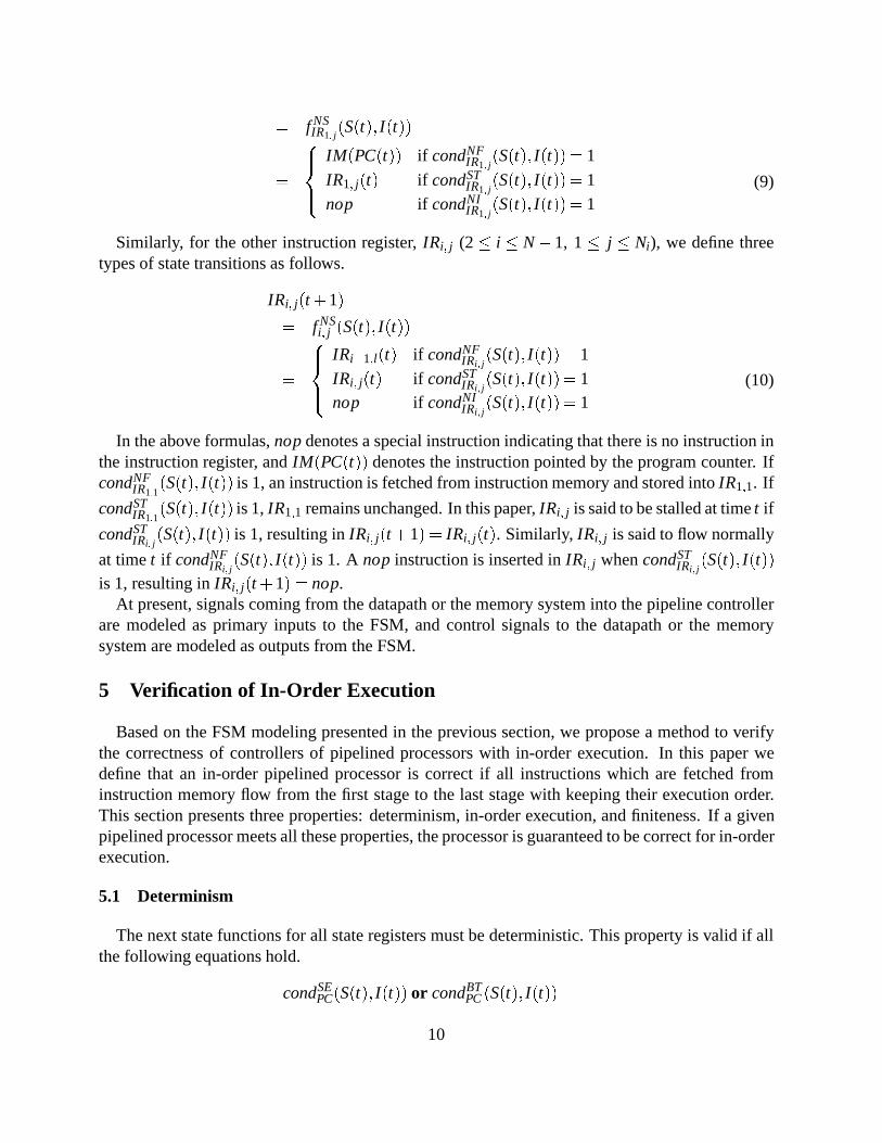
PC(S(t); I(t)) is 1,PC keeps its current value at the next cycle.For the instruction register,IR1; j (1 � j � N1), we define the following three types of state
transitions.
IR1; j(t+1)
9
= f NSIR1; j
(S(t); I(t))
=
8><>:
IM(PC(t)) if condNFIR1; j
(S(t); I(t))= 1
IR1; j(t) if condSTIR1; j
(S(t); I(t))= 1
nop if condNIIR1; j
(S(t); I(t))= 1(9)
Similarly, for the other instruction register,IRi; j (2� i � N�1, 1� j � Ni), we define threetypes of state transitions as follows.
IRi; j(t+1)
= f NSi; j (S(t); I(t))
=
8><>:
IRi�1;l(t) if condNFIRi; j
(S(t); I(t))= 1
IRi; j(t) if condSTIRi; j
(S(t); I(t))= 1nop if condNI
IRi; j(S(t); I(t))= 1
(10)
In the above formulas,nopdenotes a special instruction indicating that there is no instruction inthe instruction register, andIM(PC(t)) denotes the instruction pointed by the program counter. IfcondNF
IR1;1(S(t); I(t)) is 1, an instruction is fetched from instruction memory and stored intoIR1;1. If
condSTIR1;1
(S(t); I(t)) is 1,IR1;1 remains unchanged. In this paper,IRi; j is said to be stalled at timet if
condSTIRi; j
(S(t); I(t)) is 1, resulting inIRi; j(t+1) = IRi; j(t). Similarly, IRi; j is said to flow normally
at timet if condNFIRi; j
(S(t); I(t)) is 1. A nop instruction is inserted inIRi; j whencondSTIRi; j
(S(t); I(t))
is 1, resulting inIRi; j(t+1) = nop.At present, signals coming from the datapath or the memory system into the pipeline controller
are modeled as primary inputs to the FSM, and control signals to the datapath or the memorysystem are modeled as outputs from the FSM.
5 Verification of In-Order Execution
Based on the FSM modeling presented in the previous section, we propose a method to verifythe correctness of controllers of pipelined processors with in-order execution. In this paper wedefine that an in-order pipelined processor is correct if all instructions which are fetched frominstruction memory flow from the first stage to the last stage with keeping their execution order.This section presents three properties: determinism, in-order execution, and finiteness. If a givenpipelined processor meets all these properties, the processor is guaranteed to be correct for in-orderexecution.
5.1 Determinism
The next state functions for all state registers must be deterministic. This property is valid if allthe following equations hold.
condSEPC(S(t); I(t)) or condBT
PC(S(t); I(t))
10
or condSTPC(S(t); I(t))= 1 (11)
condNFIRi; j
(S(t); I(t)) or condSTIRi; j
(S(t); I(t))
or condNIIRi; j
(S(t); I(t))= 1;
8i; j(1� i � N�1;1� j � Ni) (12)
condxPC(S(t); I(t)) and condy
PC(S(t); I(t))= 0;
8x;y(x;y2 fSE;BT;STg ^ x 6= y) (13)
condxIRi; j
(S(t); I(t)) and condyIRi; j
(S(t); I(t))= 0;
8i; j(1� i � N�1;1� j � Ni);
8x;y(x;y2 fNF;ST;NIg ^ x 6= y) (14)
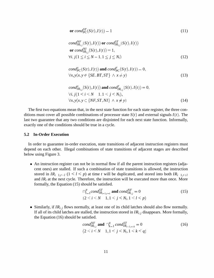
The first two equations mean that, in the next state function for each state register, the three con-ditions must cover all possible combinations of processor stateS(t) and external signalsI(t). Thelast two guarantee that any two conditions are disjointed for each next state function. Informally,exactly one of the conditions should be true in a cycle.
5.2 In-Order Execution
In order to guarantee in-order execution, state transitions of adjacent instruction registers mustdepend on each other. Illegal combinations of state transitions of adjacent stages are describedbelow using Figure 3.
� An instruction register can not be in normal flow if all the parent instruction registers (adja-cent ones) are stalled. If such a combination of state transitions is allowed, the instructionstored inIRi�1;r+l (1� l � p) at timet will be duplicated, and stored into bothIRi�1;r+l
andIRi at the next cycle. Therefore, the instruction will be executed more than once. Moreformally, the Equation (15) should be satisfied.
\pl=1condST
IRi�1;r+land condNF
IRi; j= 0 (15)
(2� i � N�1;1� j � Ni ;1� l � p)
� Similarly, if IRi; j flows normally, at least one of its child latches should also flow normally.If all of its child latches are stalled, the instruction stored inIRi; j disappears. More formally,the Equation (16) should be satisfied.
condNFIRi; j
and \qk=1 condST
IRi+1;s+k= 0 (16)
(2� i � N�1;1� j � Ni ;1� k� q)
11
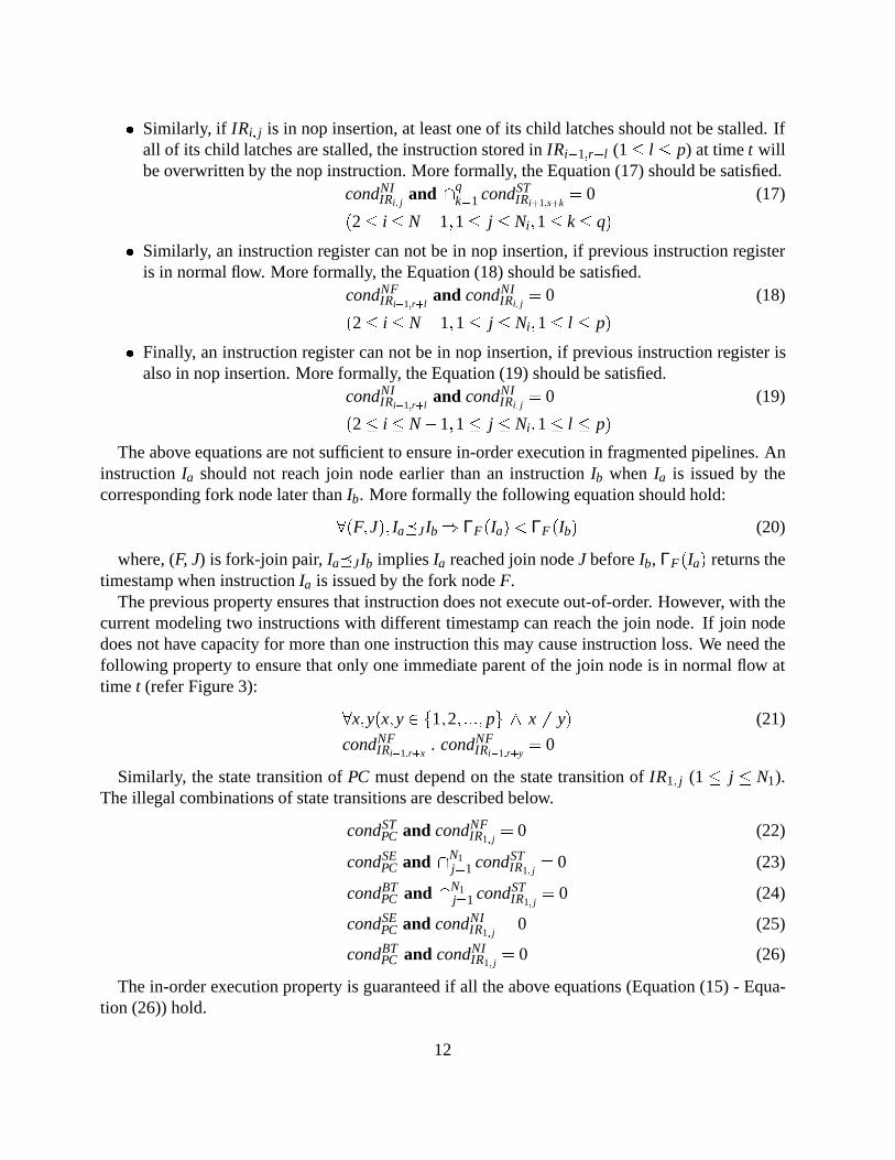
� Similarly, if IRi; j is in nop insertion, at least one of its child latches should not be stalled. Ifall of its child latches are stalled, the instruction stored inIRi�1;r+l (1� l � p) at timet willbe overwritten by the nop instruction. More formally, the Equation (17) should be satisfied.
condNIIRi; j
and \qk=1 condST
IRi+1;s+k= 0 (17)
(2� i � N�1;1� j � Ni ;1� k� q)
� Similarly, an instruction register can not be in nop insertion, if previous instruction registeris in normal flow. More formally, the Equation (18) should be satisfied.
condNFIRi�1;r+l
and condNIIRi; j
= 0 (18)
(2� i � N�1;1� j � Ni ;1� l � p)
� Finally, an instruction register can not be in nop insertion, if previous instruction register isalso in nop insertion. More formally, the Equation (19) should be satisfied.
condNIIRi�1;r+l
and condNIIRi; j
= 0 (19)
(2� i � N�1;1� j � Ni ;1� l � p)
The above equations are not sufficient to ensure in-order execution in fragmented pipelines. AninstructionIa should not reach join node earlier than an instructionIb when Ia is issued by thecorresponding fork node later thanIb. More formally the following equation should hold:
8(F;J); Ia�JIb ) ΓF(Ia)< ΓF(Ib) (20)
where, (F, J) is fork-join pair,Ia�JIb impliesIa reached join nodeJ beforeIb, ΓF(Ia) returns thetimestamp when instructionIa is issued by the fork nodeF.
The previous property ensures that instruction does not execute out-of-order. However, with thecurrent modeling two instructions with different timestamp can reach the join node. If join nodedoes not have capacity for more than one instruction this may cause instruction loss. We need thefollowing property to ensure that only one immediate parent of the join node is in normal flow attime t (refer Figure 3):
8x;y(x;y2 f1;2; :::; pg ^ x 6= y) (21)
condNFIRi�1;r+x
. condNFIRi�1;r+y
= 0
Similarly, the state transition ofPC must depend on the state transition ofIR1; j (1� j � N1).The illegal combinations of state transitions are described below.
condSTPC and condNF
IR1; j= 0 (22)
condSEPC and \N1
j=1 condSTIR1; j
= 0 (23)
condBTPC and \N1
j=1 condSTIR1; j
= 0 (24)
condSEPC and condNI
IR1; j= 0 (25)
condBTPC and condNI
IR1; j= 0 (26)
The in-order execution property is guaranteed if all the above equations (Equation (15) - Equa-tion (26)) hold.
12
5.3 Finiteness
The determinism and in-order execution properties do not guarantee that execution of instruc-tions will be completed in a finite number of cycles. In other words, the pipeline might be stalledinfinitely. Therefore, we need to guarantee that stall conditions (i.e.,condST
IRi; j) are resolved in a
finite number of cycles. As mentioned in Equation (2) pipeline stalls have two components. Bothcomponents must be resolved in a finite number of cycles. The following conditions are sufficientto guarantee the finiteness.
� A stage must flow within a finite number of cycles if all the later stages are idle. Since thiscondition may depend on external signals which come from outside of the processor core, itcannot be verified only with the FSM model. This condition is a constraint in the design ofthe blocks which generate such signals.
� condxIRi; j
(x 2 (NF;ST;NI)) can be a function of external signals and/orIRk;y wherek� i,but cannot be a function ofIRk wherek< i.
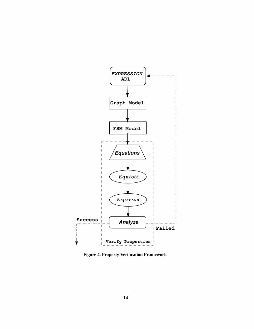
6 Property Verification Framework
In this section we describe the automatic property verification framework as shown in Figure 4.We first describe the EXPRESSION ADL which is used to capture the programmable architectures,then we discuss how the graph model is generated automatically from the ADL description. Next,we explain how to generate finite state machine model of the processor controller automaticallyfrom the graph model. This FSM model is used for verifying the in-order execution. Finally, wepresent how to verify in-order execution using this FSM modeling.
6.1 EXPRESSION ADL
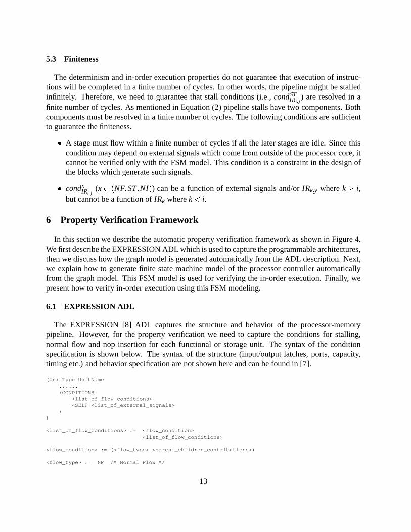
The EXPRESSION [8] ADL captures the structure and behavior of the processor-memorypipeline. However, for the property verification we need to capture the conditions for stalling,normal flow and nop insertion for each functional or storage unit. The syntax of the conditionspecification is shown below. The syntax of the structure (input/output latches, ports, capacity,timing etc.) and behavior specification are not shown here and can be found in [7].
(UnitType UnitName......(CONDITIONS
<list_of_flow_conditions><SELF <list_of_external_signals>
))
<list_of_flow_conditions> := <flow_condition>| <list_of_flow_conditions>
<flow_condition> := (<flow_type> <parent_children_contributions>)
<flow_type> := NF /* Normal Flow */
13
EXPRESSION ADL
Graph Model
FSM Model
Equations
Analyze
Espresso
Eqntott
Verify Properties
Failed
Success
Figure 4. Property Verification Framework
14
| NI /* Nop Insertion */| BT /* Branch Taken */| ST /* Stall */
<parent_children_contributions> := <parent_contribution> <child_contribution>| <child_contribution>| NULL
<parent_contribution> := <contribution><child_contribution> := <contribution>
<contribution> := NONE /* None of the parents/children can control the flow of the current node */| ANY /* Any one of the parents/children can control the flow of the current node */| SOME /* Some of the parents/children can control the flow of the current node */| ALL /* All of the parents/children can control the flow of the current node */
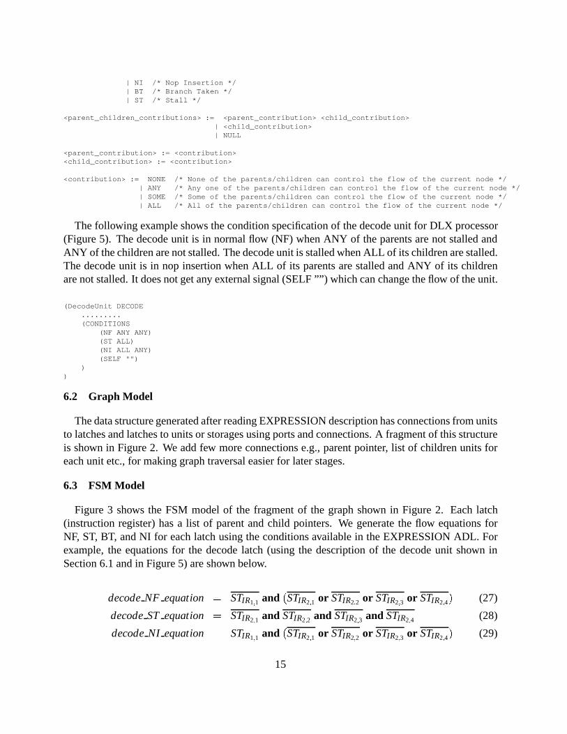
The following example shows the condition specification of the decode unit for DLX processor(Figure 5). The decode unit is in normal flow (NF) when ANY of the parents are not stalled andANY of the children are not stalled. The decode unit is stalled when ALL of its children are stalled.The decode unit is in nop insertion when ALL of its parents are stalled and ANY of its childrenare not stalled. It does not get any external signal (SELF ””) which can change the flow of the unit.
(DecodeUnit DECODE.........(CONDITIONS
(NF ANY ANY)(ST ALL)(NI ALL ANY)(SELF "")
))
6.2 Graph Model
The data structure generated after reading EXPRESSION description has connections from unitsto latches and latches to units or storages using ports and connections. A fragment of this structureis shown in Figure 2. We add few more connections e.g., parent pointer, list of children units foreach unit etc., for making graph traversal easier for later stages.
6.3 FSM Model
Figure 3 shows the FSM model of the fragment of the graph shown in Figure 2. Each latch(instruction register) has a list of parent and child pointers. We generate the flow equations forNF, ST, BT, and NI for each latch using the conditions available in the EXPRESSION ADL. Forexample, the equations for the decode latch (using the description of the decode unit shown inSection 6.1 and in Figure 5) are shown below.
decodeNF equation = STIR1;1 and (STIR2;1 or STIR2;2 or STIR2;3 or STIR2;4) (27)
decodeST equation = STIR2;1 and STIR2;2 and STIR2;3 and STIR2;4 (28)
decodeNI equation = STIR1;1 and (STIR2;1 or STIR2;2 or STIR2;3 or STIR2;4) (29)
15
6.4 Verify Properties
In this section we describe how the properties are verified using the FSM model described inSection 6.3. We first generate equations necessary for verifying properties as described in Sec-tion 5. We useeqntott tool to convert these equations in two-level representation of a two-valuedboolean function. This two-level representation is fed toespressotool which produces minimalequivalent representation. Finally, the minimized representation is analyzed to determine whetherthe property is successfully verified or not. In case of failure it generates the trace explaining thecause of failure.
Generate Equations
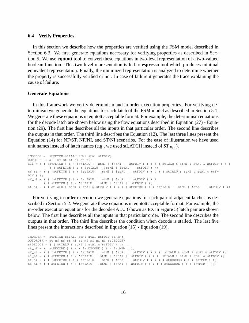
In this framework we verify determinism and in-order execution properties. For verifying de-terminism we generate the equations for each latch of the FSM model as described in Section 5.1.We generate these equations in eqntott acceptable format. For example, the determinism equationsfor the decode latch are shown below using the flow equations described in Equation (27) - Equa-tion (29). The first line describes all the inputs in that particular order. The second line describesthe outputs in that order. The third line describes the Equation (12). The last three lines present theEquation (14) for NF/ST, NF/NI, and ST/NI scenarios. For the ease of illustration we have usedunit names instead of latch names (e.g., we used stLATCH instead ofSTIR1;1).
INORDER = stFETCH stIALU stM1 stA1 stFDIV;OUTORDER = all nf_st nf_ni st_ni;all = ( ( !stFETCH ) & ( !stIALU | !stM1 | !stA1 | !stFDIV ) ) | ( ( stIALU & stM1 & stA1 & stFDIV ) ) |
( ( stFETCH ) & ( !stIALU | !stM1 | !stA1 | !stFDIV ) );nf_st = ( ( !stFETCH ) & ( !stIALU | !stM1 | !stA1 | !stFDIV ) ) & ( ( stIALU & stM1 & stA1 & stF-DIV ) );nf_ni = ( ( !stFETCH ) & ( !stIALU | !stM1 | !stA1 | !stFDIV ) ) &
( ( stFETCH ) & ( !stIALU | !stM1 | !stA1 | !stFDIV ) );st_ni = ( ( stIALU & stM1 & stA1 & stFDIV ) ) & ( ( stFETCH ) & ( !stIALU | !stM1 | !stA1 | !stFDIV ) );
For verifying in-order execution we generate equations for each pair of adjacent latches as de-scribed in Section 5.2. We generate these equations in eqntott acceptable format. For example, thein-order execution equations for the decode-IALU (shown as EX in Figure 5) latch pair are shownbelow. The first line describes all the inputs in that particular order. The second line describes theoutputs in that order. The third line describes the condition when decode is stalled. The last fivelines present the interactions described in Equation (15) - Equation (19).
INORDER = stFETCH stIALU stM1 stA1 stFDIV stMEM;OUTORDER = st_nf nf_st ni_st nf_ni ni_ni stDECODE;stDECODE = ( ( stIALU & stM1 & stA1 & stFDIV ) );st_nf = ( stDECODE ) & ( ( !stDECODE ) & ( !stMEM ) );nf_st = ( ( !stFETCH ) & ( !stIALU | !stM1 | !stA1 | !stFDIV ) ) & ( stIALU & stM1 & stA1 & stFDIV );ni_st = ( ( stFETCH ) & ( !stIALU | !stM1 | !stA1 | !stFDIV ) ) & ( stIALU & stM1 & stA1 & stFDIV );nf_ni = ( ( !stFETCH ) & ( !stIALU | !stM1 | !stA1 | !stFDIV ) ) & ( ( stDECODE ) & ( !stMEM ) );ni_ni = ( ( stFETCH ) & ( !stIALU | !stM1 | !stA1 | !stFDIV ) ) & ( ( stDECODE ) & ( !stMEM ) );
16
Generate Truth Table
We use eqntott program to convert original equations in espresso acceptable format. Eqntottgenerates a truth table suitable for PLA programming from a set of Boolean equations whichdefine the PLA outputs in terms of its inputs. We use ”-s” option, since we use some of the outputvariables as input. This program can be found inhttp://buffy.eecs.berkeley.edu/IRO/Software/Catalog/Description/platools.html
Minimize Truth Table
We use espresso program to minimize the equations that we generate for verifying the prop-erties. Espresso takes as input a two-level representation of a two-valued (or multiple-valued)Boolean function, and produces a minimal equivalent representation. This program can be foundin http://www-cad.eecs.berkeley.edu/Software/software.html
Analyze
In our framework, each equation is minimized to ’1’ or ’0’. When it is is not minimized to theboolean value, analyzer declares that as a failure and produces the trace. It compares generatedvalue (’1’ or ’0’) with the expected one ( as described in Equation (11) - Equation (26)) anddetermines whether the property holds true or not and generates necessary trace in case of failure.
7 A Case Study
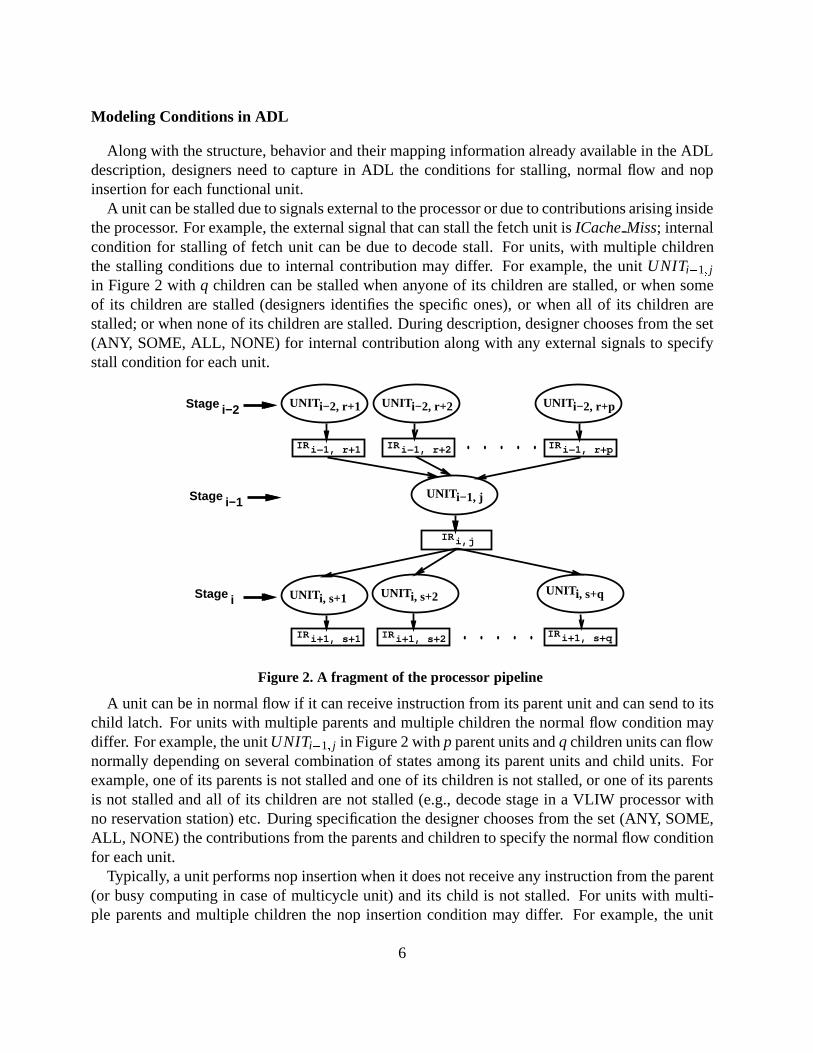
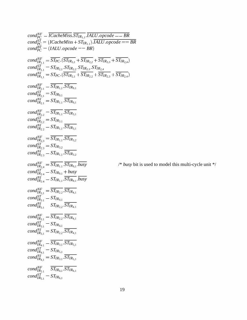
In a case study we successfully applied the proposed methodology to the DLX [11] processor.We have chosen DLX processor since it has been well studied in academia and has few interest-ing features viz., fragmented pipelines, multicycle units etc. Figure 5 shows the DLX processorpipeline.
We used EXPRESSION ADL to capture the structure and behavior of the DLX processor. Thenecessary equations for verifying the properties viz., determinism, in-order execution etc., aregenerated automatically from the given ADL description. We have used espresso to minimize theequations. These minimized equations are analyzed to verify whether the properties are violatedor not. In case of violation it displays the cause of failure. The framework is fully automated. Thecomplete verification, starting from ADL description to property verification, takes 41 seconds ona 333 MHz Sun Ultra-5 with 128M RAM.
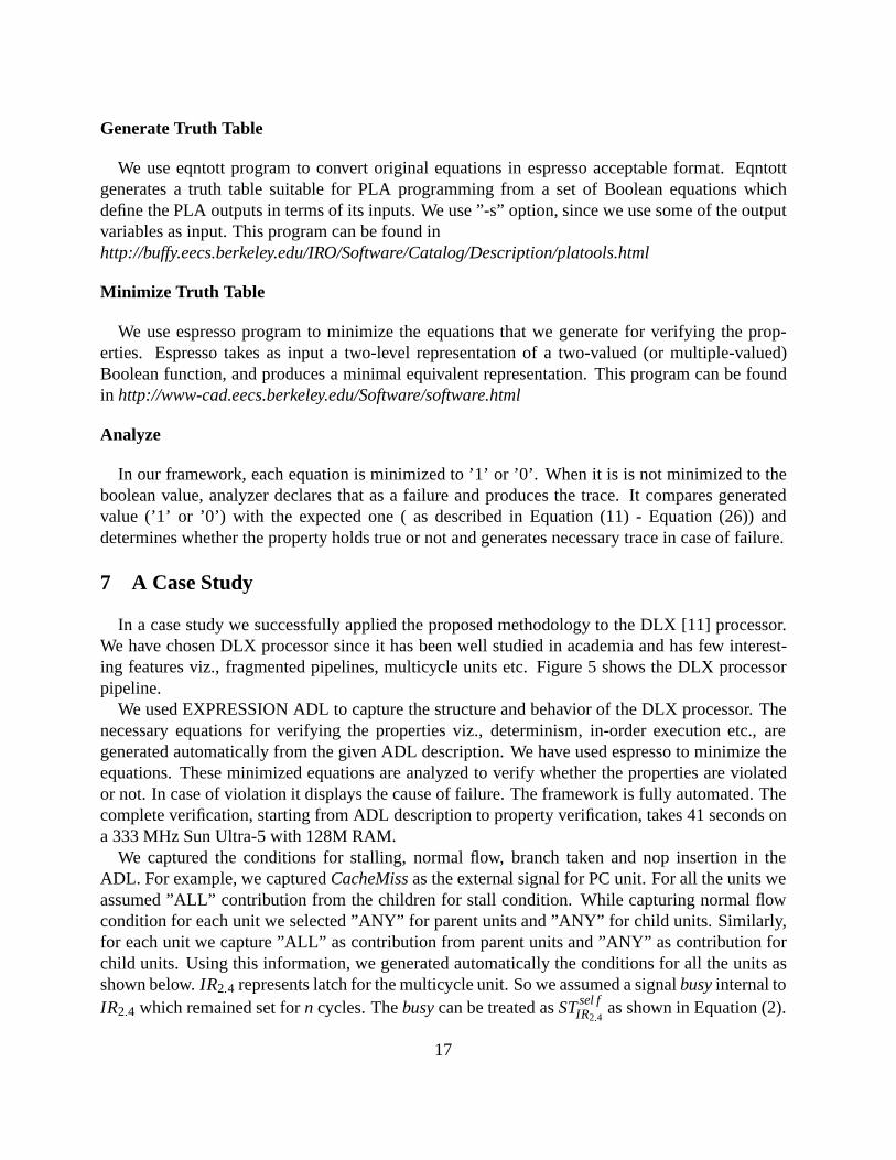
We captured the conditions for stalling, normal flow, branch taken and nop insertion in theADL. For example, we capturedCacheMissas the external signal for PC unit. For all the units weassumed ”ALL” contribution from the children for stall condition. While capturing normal flowcondition for each unit we selected ”ANY” for parent units and ”ANY” for child units. Similarly,for each unit we capture ”ALL” as contribution from parent units and ”ANY” as contribution forchild units. Using this information, we generated automatically the conditions for all the units asshown below.IR2:4 represents latch for the multicycle unit. So we assumed a signalbusyinternal toIR2:4 which remained set forn cycles. Thebusycan be treated asSTsel f
IR2:4as shown in Equation (2).
17

DIV
PC
IF
ID
EX M1
M2
M3
M5
M6
M7
A1
A2
A3
A4
MEM
WB
IR 1, 1
IR 2, 1
IR
IR
IR
IR
IR IR
IRIR
IRIR
IRIRIR
IR
2, 2 2, 3 2, 4
3, 1 3, 2
4, 1 4, 2
5, 1 5, 2
6, 1
7, 1
8, 1
9, 1
10, 1
REGISTER FILEMEMORY
M4
Figure 5. The DLX Processor
18
condNFPC = ICacheMiss:STIR1;1:IALU:opcode== BR
condSTPC = (ICacheMiss+STIR1;1):IALU:opcode== BR
condBTPC = (IALU:opcode== BR)
condNFIR1;1
= STPC:(STIR2;1+STIR2;2+STIR2;3 +STIR2;4)
condSTIR1;1
= STIR2;1:STIR2;2:STIR2;3:STIR2;4
condNIIR1;1
= STPC:(STIR2;1+STIR2;2+STIR2;3 +STIR2;4)
condNFIR2;1
= STIR1;1:STIR9;1
condSTIR2;1
= STIR9;1
condNIIR2;1
= STIR1;1:STIR9;1
condNFIR2;2
= STIR1;1:STIR3;1
condSTIR2;2
= STIR3;1
condNIIR2;2
= STIR1;1:STIR3;1
condNFIR2;3
= STIR1;1:STIR3;2
condSTIR2;3
= STIR3;2
condNIIR2;3
= STIR1;1:STIR3;2
condNFIR2;4
= STIR1;1:STIR9;1:busy /* busybit is used to model this multi-cycle unit */
condSTIR2;4
= STIR9;1+busy
condNIIR2;4
= STIR1;1:STIR9;1:busy
condNFIR3;1
= STIR2;2:STIR4;1
condSTIR3;1
= STIR4;1
condNIIR3;1
= STIR2;2:STIR4;1
condNFIR3;1
= STIR2;2:STIR4;1
condSTIR3;1
= STIR4;1
condNIIR3;1
= STIR2;2:STIR4;1
condNFIR4;1
= STIR3;1:STIR5;1
condSTIR4;1
= STIR5;1
condNIIR4;1
= STIR3;1:STIR5;1
condNFIR5;1
= STIR4;1:STIR6;1
condSTIR5;1
= STIR6;1
19
condNIIR5;1
= STIR4;1:STIR6;1
condNFIR6;1
= STIR5;1:STIR7;1
condSTIR6;1
= STIR7;1
condNIIR6;1
= STIR5;1:STIR7;1
condNFIR7;1
= STIR6;1:STIR8;1
condSTIR7;1
= STIR8;1
condNIIR7;1
= STIR6;1:STIR8;1
condNFIR8;1
= STIR7;1:STIR9;1
condSTIR8;1
= STIR9;1
condNIIR8;1
= STIR7;1:STIR9;1
condNFIR3;2
= STIR2;3:STIR4;2
condSTIR3;2
= STIR4;2
condNIIR3;2
= STIR2;3:STIR4;2
condNFIR4;2
= STIR3;2:STIR5;2
condSTIR4;2
= STIR5;2
condNIIR4;2
= STIR3;2:STIR5;2
condNFIR5;2
= STIR4;2:STIR9;1
condSTIR5;2
= STIR9;1
condNIIR5;2
= STIR4;2:STIR9;1
condNFIR9;1
= (STIR2;1+STIR8;1 +STIR5;2+STIR2;4):STIR10;1
condSTIR9;1
= STIR10;1
condNIIR9;1
= (STIR2;1:STIR8;1:STIR5;2:STIR2;4):STIR10;1
condNFIR10;1
= DCacheMiss+ IR10;1:opcode== LD
condSTIR9;1
= DCacheMiss:(IR10;1:opcode== LD)
condNIIR9;1
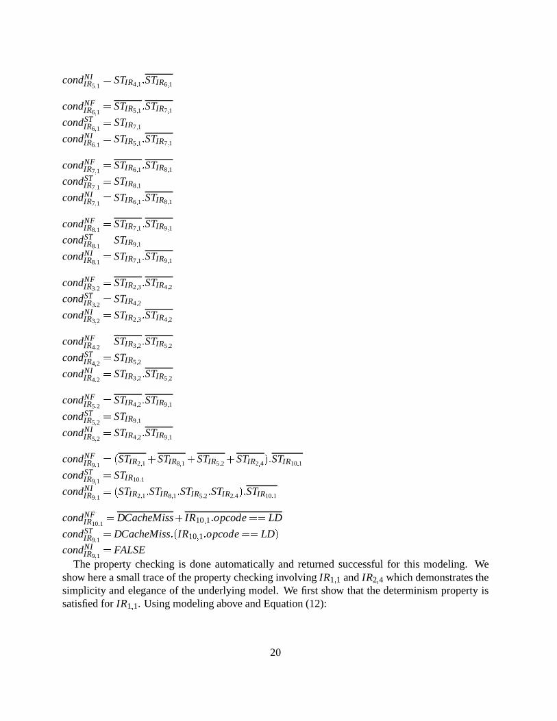
= FALSEThe property checking is done automatically and returned successful for this modeling. We
show here a small trace of the property checking involvingIR1;1 andIR2;4 which demonstrates thesimplicity and elegance of the underlying model. We first show that the determinism property issatisfied forIR1;1. Using modeling above and Equation (12):
20
condNFIR1:1
+condSTIR1:1
+condNIIR1:1
= STPC:(STIR2;1+STIR2;2+STIR2;3+STIR2;4)+STIR2;1:STIR2;2:STIR2;3:STIR2;4+STPC:(STIR2;1+STIR2;2+
STIR2;3+STIR2;4)
= (STIR2;1+STIR2;2+STIR2;3 +STIR2;4):(STPC+STPC)+STIR2;1:STIR2;2:STIR2;3:STIR2;4
= (STIR2;1+STIR2;2+STIR2;3 +STIR2;4)+STIR2;1:STIR2;2:STIR2;3:STIR2;4
= 1
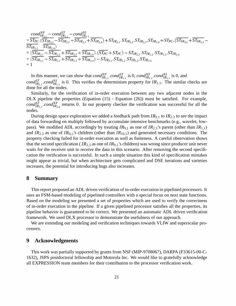
In this manner, we can show thatcondNFIR1:1
:condSTIR1:1
is 0,condNFIR1:1
:condNIIR1:1
is 0, andcondST
IR1:1:condNI
IR1:1is 0. This verifies the determinism property forIR1;1. The similar checks are
done for all the nodes.Similarly, for the verification of in-order execution between any two adjacent nodes in the
DLX pipeline the properties (Equation (15) - Equation (26)) must be satisfied. For example,condST
IR1;1:condNF
IR2;4returns 0. In our property checker the verification was successful for all the
nodes.During design space exploration we added a feedback path fromIR9;1 to IR2;3 to see the impact
of data forwarding on multiply followed by accumulate intensive benchmarks (e.g., wavelet, low-pass). We modified ADL accordingly by treatingIR9;1 as one ofIR2;3’s parent (other thanIR1;1)and IR2;3 as one ofIR9;1’s children (other thanIR10;1) and generated necessary conditions. Theproperty checking failed for in-order execution as well as finiteness. A careful observation showsthat the second specification (IR2;3 as one ofIR9;1’s children) was wrong since producer unit neverwaits for the receiver unit to receive the data in this scenario. After removing the second specifi-cation the verification is successful. In such a simple situation this kind of specification mistakesmight appear as trivial, but when architecture gets complicated and DSE iterations and varietiesincreases, the potential for introducing bugs also increases.
8 Summary
This report proposed an ADL driven verification of in-order execution in pipelined processors. Ituses an FSM-based modeling of pipelined controllers with a special focus on next state functions.Based on the modeling we presented a set of properties which are used to verify the correctnessof in-order execution in the pipeline. If a given pipelined processor satisfies all the properties, itspipeline behavior is guaranteed to be correct. We presented an automatic ADL driven verificationframework. We used DLX processor to demonstrate the usefulness of our approach.
We are extending our modeling and verification techniques towards VLIW and superscalar pro-cessors.
9 Acknowledgments
This work was partially supported by grants from NSF (MIP-9708067), DARPA (F33615-00-C-1632), JSPS postdoctoral fellowship and Motorola Inc. We would like to gratefully acknowledgeall EXPRESSION team members for their contribution to the processor verification work.
21
References
[1] ARC Cores.http://www.arccores.com.
[2] J. Burch and D. Dill. Automatic verification of pipelined microprocessor control. InCAV, 1994.
[3] G. G. et al. CHESS: Retargetable code generation for embedded DSP processors. InCode Generation forEmbedded Processors.Kluwer, 1997.
[4] G. H. et al. ISDL: An instruction set description language for retargetability. InProc. DAC, 1997.
[5] R. L. et al. Retargetable generation of code selectors from HDL processor models. InProc. EDTC, 1997.
[6] M. Freericks. The nML machine description formalism. Technical Report TR SM-IMP/DIST/08, TU Berlin CSDept., 1993.
[7] P. Grun, A. Halambi, A. Khare, V. Ganesh, N. Dutt, and A. Nicolau. EXPRESSION: An ADL for system leveldesign exploration. Technical Report TR 98-29, University Of California, Irvine, 1998.
[8] A. Halambi, P. Grun, V. Ganesh, A. Khare, N. Dutt, and A. Nicolau. EXPRESSION: A language for architectureexploration through compiler/simulator retargetability. InProc. DATE, Mar. 1999.
[9] J. Hauke and J. Hayes. Specification and verification of pipelining in the arm2 risc microprocessor. InACMTODAES, volume 3, pages 563–580, October 1998.
[10] J. Hauke and J. Hayes. Microprocessor design verification using reverse engineering. InHLDVT, pages 2–9,1999.
[11] J. Hennessy and D. Patterson.Computer Architecture: A quantitative approach. Morgan Kaufmann PublishersInc, San Mateo, CA, 1990.
[12] R. Ho, C. Yang, M. A. Horowitz, and D. Dill. Architecture validation for processors. InISCA, 1995.
[13] H. Iwashita, S. Kowatari, T. Nakata, and F. Hirose. Automatic test pattern generation for pipelined processors.In ICCAD, pages 580–583, 1994.
[14] J. Levitt and K. Olukotun. Verifying correct pipeline implementation for microprocessors. InICCAD, pages162–169, 1997.
[15] V. Rajesh and R. Moona. Processor modeling for hardware software codesign. InInternational Conference onVLSI Design, Jan. 1999.
[16] J. Skakkebaek, R. Jones, and D. Dill. Formal verification of out-of-order execution using incremental flushing.In CAV, 1998.
[17] Tensilica Incorporated.http://www.tensilica.com.
[18] H. Tomiyama, T. Yoshino, and N. Dutt. Verification of in-order execution in pipelined processors. InHLDVTWorkshop, 2000.
[19] Trimaran Release: http://www.trimaran.org.The MDES User Manual, 1997.
[20] S. Ur and Y. Yadin. Micro architecture coverage directed generation of test programs. InDAC, pages 175–180,1999.
[21] M. Velev and R. Bryant. Formal verification of superscalar microprocessors with multicycle functional units,exceptions, and branch prediction. InDAC, pages 112–117, 2000.
22