Embed Size (px)
Citation preview

ARCHIVED

Structures Design Bulletin C10-01
Bracing for New Bridge Projects
Page 2 of 6
www.dot.state.fl.us
Construction Inactive = periods during which construction activities associated with the
superstructure do not take place. Ex: For a typical girder bridge, this includes non-
work hours during which the girder bracing is to be present.
Construction Active = periods during which construction activities take place. Ex: For a
typical girder bridge, this includes girder erection, form placement and deck
concrete placement. It can be assumed that the construction active period for deck
placement is in effect until the deck concrete hardens.
RE = 0.60 if the exposure period is less than one year. The exposure period is defined as
the time period for which temporary load cases of the superstructure exist. For
example, the exposure period for a girder bridge is defined as the time period from
when the girder is set on the pedestals until the girder is made composite with the
bridge deck, and the exposure period for a segmental bridge is defined as the time
period from when segments are placed until spans are made continuous.
Note: Check limit states separately for Construction Inactive and Construction Active
wind speeds.
Table 2.4.3-2 Pressure Coefficient During Construction
COMPONENT TYPE CONSTRUCTION
CONDITION
PRESSURE
COEFFICIENT (Cp)
I-Shaped Girder Superstructure Deck forms not in place 2.2
Deck forms in place 1.1
U-Shaped and Box Girder
Superstructure
Deck forms not in place 1.5
Deck forms in place 1.1
Flat Slab or Segmental Box
Girder Superstructure
Any 1.1
Substructure Any 1.6
b. Section 4.3.1 General – Add the following to section „C‟:
For transient loads during construction the tensile stress limit may be taken as 6 f 'c .
c. Section 4.3.4 Temporary Bracing – Add this section as follows:
A. For concrete beam bridges, complete the „Table of Temporary Bracing Variables,‟ „Table
of Wind Load Variables,‟ „Table of Assumed Construction Loads,‟ and include the „Beam
Temporary Bracing‟ note (CADD Cell 20005). The tables and note are to assist the
Contractor in design of the bracing members and connections.
B. Both roll stability and service stresses shall be evaluated for Service I limit states per
Section 2.4 and AASHTO LRFD Bridge Design Specification Section 3.4.2 for the
following construction conditions:
I. Girder Placement (Construction Active) – typical loads include the girder self-weight
and construction active wind load; support conditions are un-braced beam set on
bearing pads. If beams require bracing at these loads, specify in the „Table of
Temporary Bracing Variables‟ in the Structures Plans that the beam is to be braced at
each end prior to crane release. It can be assumed that standard Florida-I beams less
than 78 inches in height with spans less than 150 feet and skews between zero and 45
degrees are stable without bracing at girder placement.
ARCHIVED

Structures Design Bulletin C10-01
Bracing for New Bridge Projects
Page 3 of 6
www.dot.state.fl.us
II. Braced Girder (Construction Inactive) – typical loads include the girder self-weight
and construction inactive wind load; support conditions are braced beam set on
bearing pads.
III. Deck Placement (Construction Active) – typical loads include girder self-weight,
construction active wind load and anticipated construction loads; support conditions
are braced beam set on bearing pads.
C. Roll Stability is to be checked according to procedures demonstrated in:
Mast, R.F (1989) “Lateral Stability of Long Prestressed Concrete Beams” Part I, PCI
Journal, Vol 34, pp. 34-53. (Available at http://www.pci.org/view_file.cfm?file=JL-
89-JANUARY-FEBRUARY-3.pdf)
Mast, R.F (1993) “Lateral Stability of Long Prestressed Concrete Beams” Part II, PCI
Journal, Vol 38, pp. 70-88. (Available at http://www.pci.org/view_file.cfm?file=JL-
93-JANUARY-FEBRUARY-30.pdf and http://www.pci.org/view_file.cfm?file=JL-
93-JANUARY-FEBRUARY-31.pdf)
The minimum factor of safety for cracking is 1.0, and the minimum factor of safety for
failure is 1.5.
D. Working stresses during construction should be evaluated at the midspan of the girder.
For simplicity, it may be assumed that full prestress losses have occurred.
E. Bracing design should be per Strength III limit states per Section 2.4 and AASHTO LRFD
Bridge Design Specification Section 3.4.2.
Commentary: The bridge designer shall check the stability of the beams after erection and
calculate the bracing locations and forces based on construction wind loads and other
assumed construction loads. The Contractor shall design the bracing members and
connections based on forces given by the bridge designer.
d. Section 6.8 Erection Scheme and Beam/Girder Stability – Replace Section 6.8 with the
following:
For all steel girder, segmental beam or box girder bridges, and C.I.P. box girder bridges on
falsework, include in the plans a workable erection scheme that addresses all major phases of
erection. Show required temporary support locations and associated loads assumed in design.
Coordinate temporary support locations with the Traffic Control Plans. For all bridges,
investigate the stability of beams or girders subjected to wind loads during construction. See
Section 4.3.4 for plan requirements for pre-tensioned beams. For the evaluation of stability
during construction use wind loads, limit states and temporary construction loads included in
the Structures Design Guidelines Section 2.4 and the AASHTO LRFD Bridge Design
Specifications. For information not included in the SDG or LRFD, refer to the AASHTO Guide
Design Specifications for Bridge Temporary Works and the AASHTO Construction Handbook
for Bridge Temporary Works.
Commentary: Investigate superstructure stability at all major phases of construction
consistent with the erection scheme shown in the plans. The Contractor is responsible for
evaluating the stability of individual components during erection.
ARCHIVED
Structures Design Bulletin C10-01
Bracing for New Bridge Projects
Page 4 of 6
www.dot.state.fl.us
2. Standard Specifications
a. Section 5-1.4.5.6 Beam and Girder Temporary Bracing – Tentative changes are as follows, to
be implemented with the January 2011 Standard Specifications:
The Contractor is solely responsible for ensuring stability of beams and girders during all
handling, storage, shipping and erection. Adequately brace beams and girders to resist wind,
weight of forms and other temporary loads, especially those eccentric to the vertical axis of the
products, considering actual beam geometry and support conditions during all stages of
erection and deck construction. At a minimum, brace girders at each end of each span.
Develop the required designs following the AASHTO LRFD Bridge Design Specifications
(LRFD), substituting wind loads found in the Structures Design Guidelines (SDG) Section
2.4.3. For information not included in the SDG or LRFD, refer to the AASHTO Guide Design
Specifications for Bridge Temporary Works and the AASHTO Construction Handbook for
Bridge Temporary Works.
For Construction Affecting Public Safety and when temporary bracing requirements are shown
in the plans, submit a Specialty Engineer‟s signed and sealed design calculations for bracing
members and connections, and for prestressed concrete beams, submit a certification statement
that construction loads do not exceed the assumed loads shown in the plans.
For Construction Affecting Public Safety and when temporary bracing requirements are not
shown in the plans or when the Contractor proposes to use a bracing system that differs from
that specified in the plans and technical special provisions, submit a Specialty Engineer‟s
signed and sealed plans and calculations for stability for all beams and girders and the plans
and design calculations for bracing members and connections.
Transmit the submittal and copies of the transmittal letters in accordance with the
requirements of 5-1.4.5.1 through 5-1.4.5.3, as appropriate.
3. Design Standards
a. Standards relating to the bracing of beams for wind load will be released with the January
2010 Interims, and are included in Attachment „B‟ of this bulletin.
COMMENTARY
The following attachments are included for evaluation of the effect of these changes:
Attachment „A‟ – Example Calculations
Attachment „B‟ – Design Standard Index 20005, Instructions for Structures Related Design
Standard Index 20005 (SDM Vol. III), CADD Cell 20005 (Table of Temporary
Bracing Variables,‟ „Table of Wind Load Variables,‟ „Table of Assumed
Construction Loads,‟ and „Beam Temporary Bracing‟ note)
ARCHIVED
Structures Design Bulletin C10-01
Bracing for New Bridge Projects
Page 5 of 6
www.dot.state.fl.us
In order to standardize the methods of temporary bracing, Design Standards relating to bracing and a
MathCAD Beam Stability Program have been developed. The Design Standard relating to bracing, Index
No. 20005, shows a sample beam and bracing layout, several bracing configurations, and includes
standard notes. The bracing sections are schematic and bracing member sizes and connections are not
specified, as the design of bracing members and connections is left to the Contractor and the Specialty
Engineer. However, the bracing sections do indicate the geometry in which bracing should be placed, and
whether tension or compression members are required, in an effort to assist Contractors in developing a
design which is in line with FDOT desired bracing schemes. The Design Standard is intended to be used
with the „Table of Temporary Bracing Variables,‟ „Table of Wind Load Variables,‟ „Table of Assumed
Construction Loads,‟ and the „Beam Temporary Bracing‟ note, all included in CADD Cell 20005.
The „Table of Temporary Bracing Variables‟ includes the span number, maximum un-braced length of
the beams, forces at each bracing point, number of bracing lines required, and whether or not end bracing
is required prior to crane release. The „Table of Wind Load Variables‟ includes the wind speed, velocity
pressure exposure coefficient, and gust effect factor. The „Table of Assumed Construction Loads‟
includes all construction loading assumptions made by the bridge designer. The tables are to be
completed by the bridge designer and included in the plans to assist the Contractor in designing bracing
members and connections. The „Beam Temporary Bracing‟ note, which clarifies the Contractor‟s
responsibilities relating to bracing, is also to be included in the plans by the bridge designer.
The inclusion of temporary bracing requirements in the design phase is a change in policy. The
Contractor is responsible for all aspects of handling, shipping, and erection but the designer is responsible
for specifying bracing requirements for stability of the beam once seated on the substructure. In addition,
the designer is to investigate beam stability at erection, while seated on the substructure without bracing
and subjected to 20 mph wind (construction active wind) and indicate whether or not end bracing is
required prior to crane release. Design Standard Index No. 20005, Instructional Design Standard Index
20005, and CADD Cell 20005 are included in Attachment „B‟ of this bulletin.
BACKGROUND
Recent national events had heightened awareness of the importance of the temporary bracing of the
bridge beams and girders during construction. This combined with the need to give the contractor the
bracing information for bidding purposes prompted this policy change. Historically, bridge designers
designed the beams or girders for the final conditions and the contactor was responsible for the stability of
the beam during the construction period. This division of responsibility does not account for the fact that
the girder stability is part of the girder design or at least influenced by the girder design. This will
eliminate the need for multiple contractors to calculate the bracing forces during bidding.
This Structures Design Bulletin implements a policy change for calculating and showing the bracing
requirement in the plans. The contractor is responsible for verifying that the construction loads do not
exceed the assumed loads in the design. The contractor is also responsible for the design of the bracing
members and connections for the bracing forces. This policy will place the responsibility for the bracing
forces with the designer who selects the bridge type, span length, girder size, and all other variables that
affect the beam stability.
ARCHIVED

Structures Design Bulletin C10-01
Bracing for New Bridge Projects
Page 6 of 6
www.dot.state.fl.us
IMPLEMENTATION
All requirements for bracing contained herein are effective immediately for all design projects with a
letting date on or after July 2011. This bulletin is not mandatory for projects currently under construction
or let prior to July 2011, but Districts may elect to incorporate the requirements into ongoing construction
and design projects at their discretion.
CONTACT
Sam Fallaha, P.E.
Assistant State Structures Design Engineer
Phone: (850) 414-4296, Fax: (850) 414-4955
E-mail: [email protected]
ARCHIVED

ATTACHMENT A
Project =DesignedBy =CheckedBy = BackCheckedBy =
Concrete I-GirderBeam Stability Program
These are calculations for the Lateral Stability of Precast Concrete Bridge Girders during construction.Instructions for use of this program are as follows:
1. Input the items under the girder properties, geometry, and loads sections highlighted in tan. For thegirders listed in the "Girder Type" pull-down menu, un-highlighted girder properties are automaticallydefined. For any other girder types, properties must be manually defined. The number of intermediatebracing points, from zero to six, represents any intermediate bracing that is to be present between thepoints of bearing. A value of zero represents no intermediate bracing points between the bearing points.
2. Check that the stress and stability checks (highlighted in yellow) read "OK." The check for stabilityat girder placement may read "Not OK," but for this case, girders must be braced prior to crane release.
3. If requirement 2 is not met, revise the number of intermediate brace points.
4. The bracing forces and maximum un-braced length are given at the end of calculations.
Girder Variables:Girder
78-in Florida-I Beam:=
Girder Type
Unit weight of Concrete wc 150 pcf⋅:=
(160 pcf per AASHTO Guide DesignSpecifications for Temporary Works)Unit weight of Concrete for deck pour wcd 160 pcf⋅:=
Concrete Strength fc' 8.5 ksi⋅:=
Effective Prestressing Force (mayassume all losses have occurred)
Pe 2189 kip⋅:=
Eccentricity of Prestressing e 29 in⋅:=
1/4/2010 1
ARCHIVED

Geometry:
Beam Span Length (centerline tocenterline bearing)
L 182 ft⋅:=
Number of Intermediate Bracing Points,(from 0 to 6)
nb 2:=
Sweep Tolerance tolS
1
8in⋅
10 ft⋅:=
Initial imperfection of bracing eb .25 in⋅:=
Skew Angle (between 0 and 60) ϕ 45 deg⋅:=
Beam Spacing S 6 ft⋅:=
Number of Beams in X-Section(from 2 to 12)
nbeam 7:=
Overhang Length (measured fromcenterline of exterior beam)
OH 3 ft⋅:=
Deflection of Deck Limit at Edge ofCantilever (recommend .25 in)
δmax .25 in⋅:=
Deck thickness (total, including IWS) td 8.5 in⋅:=
Bearing Pad Properties:
Bearing pad plan dimensions(a=width, b=length)
a 32 in⋅:= b 10 in⋅:=
When the thickness of the exteriorlayer of elastomer is equal to orgreater than one-half the thicknessof an interior layer, the parameter,n, may be increased by one-half foreach such exterior layer.
Thickness of internal elastomer layer t .5 in⋅:=
Number of interior layers of elastomer n 5:=
Elastomer Shear Modulus Gbp 127.5 psi⋅:=
1/4/2010 2
ARCHIVED

Tilt Angle of Support (Bearing PadConstruction Tolerance, recommend .01) α .01:=
Distance from Bottom of Beam to RollAxis (half bearing pad thickness)
hr 1.25 in⋅:=
Loads:
Basic Wind Speed VB 150 mph⋅:=
Wind Speed Factor for ConstructionInactive Wind Speed
RE 0.6:= V RE VB⋅ 90 mph⋅=:=
Construction Active Wind Speed (20MPH recommended)
VE 20 mph⋅:=
Construction Wind Load Factor γ 1.25:=
Gust effect factor G 0.85:=
Pressure Coefficient, single girder Cpg 2.2:=
Pressure Coefficient, entire bridgesection
Cp 1.1:=
Bridge Height, measured tomid-height of beam (ft) Height 60 ft⋅:=
Velocity Pressure Exposure Coefficient Kz max 2.01Height900 ft⋅
.2105⋅ 0.85,
1.137=:=
Construction Active Wind Load forsingle girder
wwE 0.00256 Kz⋅ G⋅ Cpg⋅VEmph
2
⋅ psf⋅ 2.177 psf⋅=:=
Construction Inactive Wind Load forsingle girder
ww 0.00256 Kz⋅ G⋅ Cpg⋅V
mph
2⋅ psf⋅ 44.075 psf⋅=:=
Construction Active Wind Load forentire bridge section wwD 0.00256 Kz⋅ G⋅ Cp⋅
VEmph
2
⋅ psf⋅ 1.088 psf⋅=:=
Weight of build-up wb 50 plf⋅:=
1/4/2010 3
ARCHIVED

Weight of forms (20 psf recommended) wf 20 psf⋅:=
Live loads during deck pour (20 psf and75 plf at edge of overhang per AASHTOGuide Design Specifications forTemporary Works)
wl 20 psf⋅:= Pl 75 plf⋅:=
(recommend 10 kips forbridge widths less than 45feet and 20 kipsotherwise)
Total Weight of finishing machine wfm 20 kip⋅:=
Wheel Location of finishing machine inrelation to edge of overhang, positiveis to exterior of overhang edge,negative is to interior of overhangedge
dfm 2.5 in⋅:= (+2.5 in. recommended)
Girder Properties
Reference to Excel Properties file Properties READFILE "BeamProp.xls" "Excel", ( ):=
Unbraced Length of Beam LbL
nb 1+60.667ft=:=
Height h PropertiesGirder 1, in⋅ 78 in⋅=:=
Top flange width bt PropertiesGirder 2, in⋅ 48 in⋅=:=
Bottom flange width bb PropertiesGirder 3, in⋅ 38 in⋅=:=
Modulus of Elasticity Ec 0.9 57000⋅fc'psi
0.5
⋅ psi⋅ 4.73 103× ksi⋅=:=
Shear Modulus Gshear .416667 Ec⋅ 1.971 103× ksi⋅=:=
Area of Concrete Ac PropertiesGirder 4, in2⋅ 1.101 103× in2⋅=:=
Moment of Inertia, about x-axis Ix PropertiesGirder 5, in4⋅ 904567 in4⋅=:=
1/4/2010 4
ARCHIVED

Moment of Inertia, about y-axis Iy PropertiesGirder 6, in4⋅ 82367 in4⋅=:=
Distance from CG to top of beam yt PropertiesGirder 7, in⋅ 43.4 in⋅=:=
Distance from CG to bottom of beam yb PropertiesGirder 8, in⋅ 34.6 in⋅=:=
Torsional Constant J PropertiesGirder 9, in4⋅ 33291 in4⋅=:=
StIxyt
20843 in3⋅=:= SbIxyb
26144 in3⋅=:= Section moduli about x-axisSection Moduli
Syt2 Iy⋅
bt3432 in3⋅=:= Syb
2 Iy⋅
bb4335 in3⋅=:= Section moduli about y-axis
Self-weight of beam and deck w Ac wc⋅ 1.146 103× plf⋅=:= wd td wcd⋅ 113.333 psf⋅=:=
Lateral Deflection and Eccentricity of Girder Center of Gravity: This is the theoretical maximum lateraldeflection of the beam based on beamself-weight if cracking did not occurMaximum Lateral Deflection of
Uncracked Section zow L4⋅
120 Ec⋅ Iy⋅46.496 in⋅=:=
Based on the sweep tolerance and 1.5"limit per the Specifications, this ismaximum sweep that could occur, the2/3 factor is included because theaverage location of the CG over thelength of the beam is 2/3 of themaximum sweep
Eccentricity due to Sweep es min 1.5 in⋅ L tolS⋅, ( ) 2
31 in⋅=:=
Eccentricity due to constructioninactive wind speed
ewww h⋅ L4⋅
120 Ec⋅ Iy⋅11.619 in⋅=:=
Eccentricity due to wind loading atconstruction active wind speed,girder only
ewEwwE h⋅ L4⋅
120 Ec⋅ Iy⋅0.574 in⋅=:= Lateral deflection due to wind, based on
uncracked section
Eccentricity due to wind loading atconstruction active wind speed,entire bridge section
ewDwwD h⋅ L4⋅
120 Ec⋅ Iy⋅0.287 in⋅=:=
1/4/2010 5
ARCHIVED

Bearing Pad Rotational Stiffness Range of possible length:width ratios ofbearing padb_a .5 .6 .7 .75 .8 .9 1 1.2 1.4 2 4 10 1000( ):=
C 136.7 116.7 104.4 100 96.2 90.4 86.2 80.4 76.7 70.8 64.9 61.9 60( ):= Range of possible coefficient based onlength:width ratio
C' linterp b_aT CT, ba
,
174.2=:= Coefficient based on length:width ratio
Effect of Skew on Stiffness (coefficient) Ang 0 15 30 45 60( ):=
Range of stiffness coefficients per skewper UF Structures Research Report2007/52290
Stiffness .8883 .5922 .4666 .3948 .323( ):=
Bearing Pad Rotational Stiffness Kθ linterp AngT StiffnessT, ϕ
deg,
Gbp a5⋅ b⋅
C' n⋅ t3⋅⋅ 155134.736
kip in⋅
rad⋅=:=
Coefficient for Reaction at Bracingbased on number of brace points,i=intermediate, e=end
kvi
0
1.25
1.1
1.143
1.132
1.135
1.134
:= kve
.5
.375
.4
.393
.395
.395
.395
:= Kvi kvinb1.1=:=
Kve kvenb0.4=:=
km
.12513
.07818
.06396
.06481
.06349
.06377
.06298
.12513
.05212
.04357
.04321
.04294
.04251
.04227
.12513
.03905
.03337
.0324
.03267
.03189
.0319
.12513
.03128
.02725
.02592
.02651
.02551
.02569
.12513
.02874
.02317
.02181
.02239
.02136
.02155
.12513
.02697
.02026
.01899
.01946
.01847
.01858
.12513
.02569
.01808
.01689
.01726
.0163
.01636
.12513
.02472
.01637
.01526
.01554
.01462
.01464
.12513
.02395
.01501
.01395
.01417
.01327
.01326
.12513
.02333
.01391
.01289
.01306
.01216
.01213
.12513
.02281
.01344
.01199
.01212
.01125
.01119
:=
Coefficient for Bending Moment inGirder based on number of brace points
KM kmnb nbeam 2−, 0.02026=:=
1/4/2010 6
ARCHIVED

Calculation of Bending Moments:
Unfactored vertical load during deck placement for ext. beam (not including finishing machine) Includes self-wt of girder, build-up,forms, wet concrete deck, andconstruction live loadswD.ext w wb+ Pl+ wd wl+( ) .5 S⋅ OH+( )⋅+ wf .5 S⋅ OH+ bt−( )⋅+ 2.11 klf⋅=:=
wD.int w wb+ wd wl+( ) S⋅+ wf S bt−( )⋅+ 2.036 klf⋅=:=
Strength I Torsional Distributed Overhang Moment during deck placement
Mc 1.25 wd wf+( )⋅ 1.5 wl⋅+ OH .5 bt⋅−( )⋅ .5 bt⋅ .5 OH .5 bt⋅−( )⋅+ ⋅ 1.5 Pl⋅ OH⋅+ 0.83kip ft⋅
ft⋅=:= Includes all construction loads except
finishing machineStrength I Torsional Finishing MachineMoment
Mfm 1.25 .5⋅ wfm⋅ OH dfm+( )⋅ 40.104 kip ft⋅⋅=:= Finishing Machine Moment at eachexterior girder
Lateral Moment Due to ConstructionInactive wind speed
Mw KM ww⋅ h⋅ L2⋅ 2307 kip in⋅⋅=:=
Vertical Moment due togirder self-weight
Mgw L2⋅
856962 kip in⋅⋅=:=
Lateral Moment Due to ConstructionActive Wind speed, braced condition
MwE KM wwE⋅ h⋅ L2⋅ 114 kip in⋅⋅=:=
Lateral Moment Due to ConstructionActive Wind speed, unbraced condition
MwE.u .125 wwE⋅ h⋅ L2⋅ 703 kip in⋅⋅=:=
Vertical Moment due to self-weight andconstruction loads during deck placement, exterior girder
MgDwD.ext L2⋅ wfm L⋅+
8110369 kip in⋅⋅=:=
Service Stress Check for Girder Placement, prior to beam bracing:
Assumes creep factor is 2.0Camber (approx.) δc
L2 Pe e⋅5w L2⋅
48−
⋅ 2⋅
8 Ec⋅ Ix⋅4.463 in⋅=:=
The camber is multipled by 2/3 becausethe average location of the CG over thelength of the beam is 2/3 of themaximum camber
Distance from Center ofGravity to Roll Axis y yb hr+ δc
2
3⋅+ 38.825 in⋅=:=
1/4/2010 7
ARCHIVED

Elastic Rotational Spring Constant(sum of 2 bearing pads) Kθ 155134.736
kip in⋅
rad⋅=
Per Mast Part 2, r is the height at whichthe total beam weight could be placedto cause neutral equilibrium with thespring for a given small angle
Radius of Stability rKθw L⋅
61.959 ft=:=
Stress at Top of Beam, Tension fttEPeAc
−Pe e⋅
St+
MgSt
−MwE.u
Syt+ 1.471− ksi⋅=:= Sign convention is tension=positive,
compression=negative
Stress at Top of Beam, Compression ftcEPeAc
−Pe e⋅
St+
MgSt
−MwE.u
Syt− 1.881− ksi⋅=:=
Compression Check CkE.t.comp if ftcE 6fc'psi
⋅ psi⋅≤ ftcE 0.6− fc'⋅≥∧ 1, 0,
1=:=
Tension Check CkE.t.tens if fttE 6fc'psi
⋅ psi⋅≤ fttE 0.6− fc'⋅≥∧ 1, 0,
1=:=
Stress at Bottom of Beam, Tension fbtEPeAc
−Pe e⋅
Sb−
MgSb
+MwE.u
Syb+ 2.076− ksi⋅=:=
Stress at Bottom of Beam, Compression fbcEPeAc
−Pe e⋅
Sb−
MgSb
+MwE.u
Syb− 2.4− ksi⋅=:=
Compression CheckCkE.b.comp if fbcE 6
fc'psi
⋅ psi⋅≤ fbcE 0.6− fc'⋅≥∧ 1, 0,
1=:=
Tension CheckCkE.b.tens if fbtE 6
fc'psi
⋅ psi⋅≤ fbtE 0.6− fc'⋅≥∧ 1, 0,
1=:=
Check for stress at girder placement
Ckstress.plcmnt if min CkE.t.comp CkE.t.tens, CkE.b.comp, CkE.b.tens, ( ) 1= "OK", "Not OK", ( ) "OK"=:=
1/4/2010 8
ARCHIVED

Roll Stability Check for Girder Placement, prior to beam bracing:
Modulus of Rupture fr 7.5 fc'⋅ psi⋅ 691.466 psi⋅=:=
Lateral Cracking Moment Mlat minfr fttE−( ) Iy⋅
bt2
fr fbtE−( ) Iy⋅
bb2
,
7422.697 kip in⋅⋅=:= Y-direction moment that causes cracking
Rotation Angle at Cracking θcrMlatMg
0.13 rad⋅=:=
Rotation Angle at Failure
θf min 0.4
5 zo⋅ α⋅ 5 zo⋅ α⋅( )2 10 zo⋅ es ewE+ α zo⋅+ 2.5 ewE⋅ α⋅+ y α⋅+wwE h2⋅
2 w⋅+
⋅+
.5
+
5 zo⋅,
0.169=:= θ and θf are adapted from Mast Part 2to include effects of erection wind load
θα r⋅ es+ ewE+
wwE h2⋅
2 w⋅+
r y− zo−0.0144 rad⋅=:=Final Rotation
Factor of Safety for Cracking(Unbraced Beam)
FScrr θcr α−( )⋅
zo θcr⋅ es+ ewE+ y θcr⋅+wwE h2⋅
2 w⋅+
6.8=:= Factors of safety are adapted from MastPart 2 to include effects of erection windload
Factor of Safety for Failure(Unbraced Beam)
FSfr θf α−( )⋅
zo 1 2.5 θf⋅+( )⋅ θf⋅ es+ ewE 1 2.5 θf⋅+( )⋅+ y θf⋅+wwE h2⋅
2 w⋅+
5.9=:=
Check for stability at girder placement
Ckstab.plcmnt if θ 0≥( ) FScr 1≥( )∧ FSf 1.5≥( )∧ "OK", "Not OK", "OK"=:=
1/4/2010 9
ARCHIVED

Service Stress Check for braced beam, prior to deck placement:
Stress at Top of Beam, Tension fttPeAc
−Pe e⋅
St+
MgSt
−MwSyt
+ 1.004− ksi⋅=:= Sign convention is tension=positive,compression=negative
Stress at Top of Beam, Compression ftcPeAc
−Pe e⋅
St+
MgSt
−MwSyt
− 2.348− ksi⋅=:=
Compression Check CkB.t.comp if ftc 6fc'psi
⋅ psi⋅≤ ftc 0.6− fc'⋅≥∧ 1, 0,
1=:=
Tension Check CkB.t.tens if ftt 6fc'psi
⋅ psi⋅≤ ftt 0.6− fc'⋅≥∧ 1, 0,
1=:=
Stress at Bottom of Beam, Tension fbtPeAc
−Pe e⋅
Sb−
MgSb
+MwSyb
+ 1.706− ksi⋅=:=
Stress at Bottom of Beam, Compression fbcPeAc
−Pe e⋅
Sb−
MgSb
+MwSyb
− 2.771− ksi⋅=:=
Compression CheckCkB.b.comp if fbc 6
fc'psi
⋅ psi⋅≤ fbc 0.6− fc'⋅≥∧ 1, 0,
1=:=
Tension CheckCkB.b.tens if fbt 6
fc'psi
⋅ psi⋅≤ fbt 0.6− fc'⋅≥∧ 1, 0,
1=:=
Check for stress at braced condition
Ckstress.braced if min CkB.t.comp CkB.t.tens, CkB.b.comp, CkB.b.tens, ( ) 1= "OK", "Not OK", ( ) "OK"=:=
1/4/2010 10
ARCHIVED

Roll Stability Check for braced beam, prior to deck placement: The initial rotation is caused by theimperfections in the girder and girdersupport. Additionally, it can beexpected that the wind load will causethe maximum "play" in the bracing tobe achieved, which results in aneccentricity of eb. The initial rotation isthe maximum rotation that is seen at thebracing points. Any additionalrotation is between the bracing pointsin the form of torque. The torque iscaused by the fact that the CG of thebeam is not in line with the supportsdue to eccentricity.
Initial Rotation θiα r⋅ es+
r y− zo−
min eb ew, ( )y
+ 0.019=:=
Maximum Torque between bracing points TB w L⋅ ew⋅ 202.031 kip ft⋅⋅=:=
Twist due to torque ϕBTB .5⋅ Lb⋅
Gshear J⋅0.013=:=
Total Rotation θw θi ϕB+ 0.0327=:=
Rotation Limits θw.max min θcr 5 deg⋅, ( ) 0.087=:=It makes sense to prevent cracking ofthe beam, as the strength of the beam iscompromised once cracking occurs. Areasonable upper bound limit is 5degrees. Per Mast Part 2, crackingoccurs in many beams at 5 degrees.
Wind Load Rotation Check FSθwθw.maxθw
2.668=:=
Ckstab.braced if FSθw 1≥ "OK", "Not OK", ( ) "OK"=:=
Service Stress Check for braced beam, during deck placement:
Stress at Top of Beam, Tension fttDPeAc
−Pe e⋅
St+
MgDSt
−MwESyt
+ 4.205− ksi⋅=:= Sign convention is tension=positive,compression=negative
Stress at Top of Beam, Compression ftcDPeAc
−Pe e⋅
St+
MgDSt
−MwESyt
− 4.272− ksi⋅=:=
Compression Check CkD.t.comp if ftcD 6fc'psi
⋅ psi⋅≤ ftcD 0.6− fc'⋅≥∧ 1, 0,
1=:=
Tension Check CkD.t.tens if fttD 6fc'psi
⋅ psi⋅≤ fttD 0.6− fc'⋅≥∧ 1, 0,
1=:=
Stress at Bottom of Beam, Tension fbtDPeAc
−Pe e⋅
Sb−
MgSb
+MwESyb
+ 2.212− ksi⋅=:=
1/4/2010 11
ARCHIVED

Stress at Bottom of Beam, Compression fbcDPeAc
−Pe e⋅
Sb−
MgSb
+MwESyb
− 2.265− ksi⋅=:=
Compression CheckCkD.b.comp if fbcD 6
fc'psi
⋅ psi⋅≤ fbcD 0.6− fc'⋅≥∧ 1, 0,
1=:=
Tension CheckCkD.b.tens if fbtD 6
fc'psi
⋅ psi⋅≤ fbtD 0.6− fc'⋅≥∧ 1, 0,
1=:=
Check for stress at deck placement condition
Ckstress.deck if min CkD.t.comp CkD.t.tens, CkD.b.comp, CkD.b.tens, ( ) 1= "OK", "Not OK", ( ) "OK"=:=
Roll Stability Check during Deck Placement:
Lateral Cracking Moment MlatD minfr fttD−( ) Iy⋅
.5 bt⋅
fr fbtD−( ) Iy⋅
.5 bb⋅,
1.259 104× kip in⋅⋅=:= Y-direction moment that causes cracking
Rotation Angle at Cracking θcrDMlatDMgD
0.114 rad⋅=:=
The initial rotation is caused by theimperfections in the girder and girdersupport. Additionally, it can beexpected that the construction loadswill cause the maximum "play" in thebracing to be achieved, which results inan eccentricity of eb. The initialrotation is the maximum rotation that isseen at the bracing points. Anyadditional rotation is between thebracing points in the form of torque.The torque is caused by theconstruction live loads acting on theoverhang of the bridge, eccentric to thecenterline of the exterior girder.
Initial Rotation θi.Dα r⋅ es+
r y− zo−
min eb ewD, ( )y
+ 0.019=:=
Torque due to construction live loads TD .5 wfm⋅ Pl Lb⋅+( ) OH dfm+( )⋅ 46.681 kip ft⋅⋅=:=
Twist due to construction live loads ϕDTD .5⋅ Lb⋅
Gshear J⋅0.0031=:=
Deflection at cantilever due to twist δD OH tan ϕD( )⋅ 0.112 in⋅=:=
Total Rotation θD θi.D ϕD+ 0.022=:=
Rotation Limits θD.max min θcrD 5 deg⋅, ( ) 0.087=:=
Deck Placement Rotation Check Ckstab.deck if δD δmax≤ θD θD.max≤∧ "OK", "Not OK", ( ) "OK"=:=
1/4/2010 12
ARCHIVED

Bracing Requirements:
Factored Horizontal Force at Each Beam End and Anchor Brace, at midheight of beamFe ww γ⋅ h⋅ Lb⋅ Kve⋅ 8.69 kip⋅=:=
Factored Horizontal Bracing Force at Each Intermediate SpanBrace (if present), at mid-height of beam
Fi if nb 0= "N/A", ww γ⋅ h⋅ Lb⋅ Kvi⋅, ( ) 23.898 kip⋅=:=
Factored Overturning Force at Each Beam End and Anchor Brace, at top of beam
Me Mfm Mc Lb⋅ Kve⋅+ wwD γ⋅ h⋅ Lb⋅ Kve⋅ .5⋅ h⋅+ .9 w⋅ Lb⋅bb2
zo θi.D⋅ es+ min eb ewD, ( )+ y θi.D⋅+( )−
⋅ Kve⋅− 27.31 kip ft⋅⋅=:=
Factored Overturning Force at Each Intermediate Span Brace (if present), at top of beam
Mi Mfm Mc Lb⋅ Kvi⋅+ wwD γ⋅ h⋅ Lb⋅ Kvi⋅ .5⋅ h⋅+ .9 w⋅ Lb⋅bb2
zo θi.D⋅ es+ min eb ewD, ( )+ y θi.D⋅+( )−
⋅ Kve⋅− 63.747 kip ft⋅⋅=:=
Verification of Bracing Adequacy
Stress Checks
Ckstress.plcmnt "OK"=
Ckstress.braced "OK"=
Ckstress.deck "OK"=
Stability Checks
Ckstab.plcmnt "OK"= If Ckstab.plcmnt is "Not OK," the girder must be braced prior to crane release.
Ckstab.braced "OK"=
Ckstab.deck "OK"=
1/4/2010 13
ARCHIVED

Temporary Bracing Variables
Maximum Un-braced Length Lb 60.667 ft=
Factored Horizontal Force at Each Beam End andAnchor Brace, at mid-height of beam Fe 8.69 kip⋅=
Factored Horizontal Bracing Force at EachIntermediate SpanBrace (if present), at mid-height ofbeam
Fi 23.898 kip⋅=
Factored Overturning Force at Each Beam End andAnchor Brace, at top of beam Me 27.31 kip ft⋅⋅=
Factored Overturning Force at Each IntermediateSpan Brace (if present), at top of beam Mi 63.747 kip ft⋅⋅=
Wind Load Variables
Basic Wind Speed VB 150 mph⋅=
Construction Inactive Wind Speed V 90 mph⋅=
Construction Active Wind Speed VE 20 mph⋅=
Velocity Pressure Exposure Coefficient Kz 1.137=
Gust effect factor G 0.85=
Assumed Construction Loads
Weight of build-up wb 50 plf⋅=
Form Weight wf 20 psf⋅=
Finishing Machine Total Weight wfm 20 kip⋅=
Finishing Machine Wheel LocationBeyond Edge of Deck Overhang dfm 2.5 in⋅=
Deck Weight wd 113.333 psf⋅=
Live load wl 20 psf⋅=
Live Load at Extreme Deck Edge Pl 75 plf⋅=
1/4/2010 14
ARCHIVED
| Beam
| Beam
| Beam
| Beam
| Beam
| Beam
| Beam
| Beam
| Beam
| Beam
TT&C
T&C
T&C
T&C
T&C
T&C
T
T&C
T&C
T&C
Brace Member (Typ.) Brace Member (Typ.)
Anchor Bracing
Anchor Bracing
Brace Member (Typ.)
Brace Member (Typ.)
Brace Member (Typ.)
Anchor Beam
(Location Varies)
End Span
Bracing (Typ.)
End Span
Bracing (Typ.)
Intermediate Span
Bracing (Typ.)
Sheet No.
Index No.
2010 FDOT Design StandardsRevision
20005
01/01/10 1 of 1
Last
PRESTRESSED BEAM TEMPORARY BRACING
L L LB B B
PRESTRESSED BEAM TEMPORARY BRACING PLAN VIEW
(Skewed Condition Shown, Non-skewed Condition Similar)
T&CT&C
LEGEND:
T = Tension Member
T&C = Tension & Compression Member
Bridge Span (´-´ Bearing)
4’-0" Max. to ´ Bearing (Typ.)
´ Bearing (Typ.) 4’-0" Max. to
´ Pier or Bent,
or Front Face
of Backwall
´ Pier or Bent,
or Front Face
of Backwall
EXAMPLE ANCHOR BRACING TYPICAL SECTIONS
(Beam Ends Only)
EXAMPLE END SPAN/INTERMEDIATE BRACING TYPICAL SECTIONS
REVISIONSDescriptionByDate ByDate Description
01/01/10 SJN New Design Standard
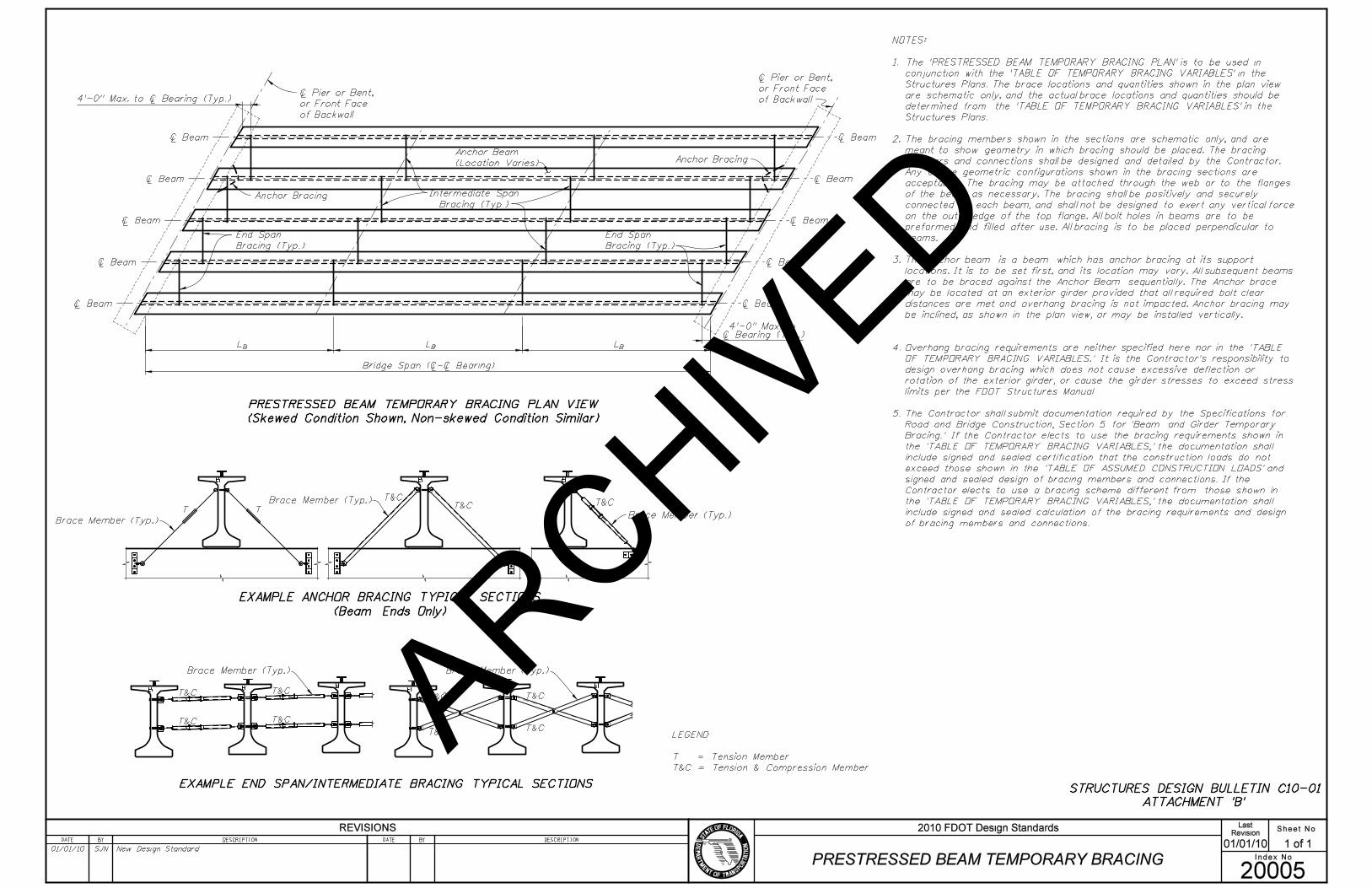
NOTES:
1. The ’PRESTRESSED BEAM TEMPORARY BRACING PLAN’ is to be used in
conjunction with the ’TABLE OF TEMPORARY BRACING VARIABLES’ in the
Structures Plans. The brace locations and quantities shown in the plan view
are schematic only, and the actual brace locations and quantities should be
determined from the ’TABLE OF TEMPORARY BRACING VARIABLES’ in the
Structures Plans.
2. The bracing members shown in the sections are schematic only, and are
meant to show geometry in which bracing should be placed. The bracing
members and connections shall be designed and detailed by the Contractor.
Any of the geometric configurations shown in the bracing sections are
acceptable. The bracing may be attached through the web or to the flanges
of the beam, as necessary. The bracing shall be positively and securely
connected to each beam, and shall not be designed to exert any vertical force
on the outer edge of the top flange. All bolt holes in beams are to be
preformed and filled after use. All bracing is to be placed perpendicular to
beams.
3. The anchor beam is a beam which has anchor bracing at its support
locations. It is to be set first, and its location may vary. All subsequent beams
are to be braced against the Anchor Beam sequentially. The Anchor brace
may be located at an exterior girder provided that all required bolt clear
distances are met and overhang bracing is not impacted. Anchor bracing may
be inclined, as shown in the plan view, or may be installed vertically.
4. Overhang bracing requirements are neither specified here nor in the ’TABLE
OF TEMPORARY BRACING VARIABLES.’ It is the Contractor’s responsibility to
design overhang bracing which does not cause excessive deflection or
rotation of the exterior girder, or cause the girder stresses to exceed stress
limits per the FDOT Structures Manual.
5. The Contractor shall submit documentation required by the Specifications for
Road and Bridge Construction, Section 5 for ’Beam and Girder Temporary
Bracing.’ If the Contractor elects to use the bracing requirements shown in
the ’TABLE OF TEMPORARY BRACING VARIABLES,’ the documentation shall
include signed and sealed certification that the construction loads do not
exceed those shown in the ’TABLE OF ASSUMED CONSTRUCTION LOADS’ and
signed and sealed design of bracing members and connections. If the
Contractor elects to use a bracing scheme different from those shown in
the ’TABLE OF TEMPORARY BRACING VARIABLES,’ the documentation shall
include signed and sealed calculation of the bracing requirements and design
of bracing members and connections.
STRUCTURES DESIGN BULLETIN C10-01
ATTACHMENT ’B’
ARCHIVED
SPAN
NO.
TABLE OF TEMPORARY BRACING VARIABLES
TOTAL
NUMBER
OF
BRACES
BL ,
MAXIMUM
UNBRACED
LENGTH (FT)
1
2
3
60.67
60.67
60.67
NO
NO
NO
24
24
24
27.31
27.31
27.31
OVERTURNING
FORCE AT EACH BEAM
END AND ANCHOR
BRACE (KIPxFT)
HORIZONTAL FORCE
AT EACH BEAM
END AND ANCHOR
BRACE (KIP)
TABLE OF WIND LOAD VARIABLES
WIND SPEED, BASIC (MPH)
WIND SPEED, CONSTRUCTION INACTIVE (MPH)
WIND SPEED, CONSTRUCTION ACTIVE (MPH)
GUST EFFECT FACTOR
150
0.85
90
20
DECK WEIGHT (PSF)
20
20
TABLE OF ASSUMED CONSTRUCTION
LOADS (UNFACTORED)
BUILD-UP (PLF)
FORM WEIGHT (PSF)
FINISHING MACHINE TOTAL WEIGHT (KIP)
FINISHING MACHINE WHEEL LOCATION
BEYOND EDGE OF DECK OVERHANG (IN.)
LIVE LOAD (PSF)
LIVE LOAD AT EXTREME DECK EDGE (PLF)
50
113.3
20
75
8.69
8.69
8.69
23.90
23.90
23.90
63.75
63.75
63.75
VELOCITY PRESSURE EXPOSURE COEFFICIENT 1.137
2�
HORIZONTAL
FORCE AT EACH
INTERMEDIATE SPAN
BRACE (KIP)
OVERTURNING
FORCE AT EACH
INTERMEDIATE SPAN
BRACE (KIPxFT)
BRACE ENDS
PRIOR
TO CRANE
RELEASE?
GENERAL INSTRUCTIONS:
IN
ST
RU
CTIO
NA
L
NO
TE
S
TO
DE
SIG
NE
RS
EX
AM
PL
E
PR
OB
LE
M
Table Date 1-01-10
Table Date 1-01-10
Table Date 1-01-10
Sheet No.Revision
01/01/10 1 of 1
Index No.(s)PRESTRESSED BEAM TEMPORARY
BRACING INSTRUCTIONS
LastDesign Instructions & Information For FDOT Design Standards
20005
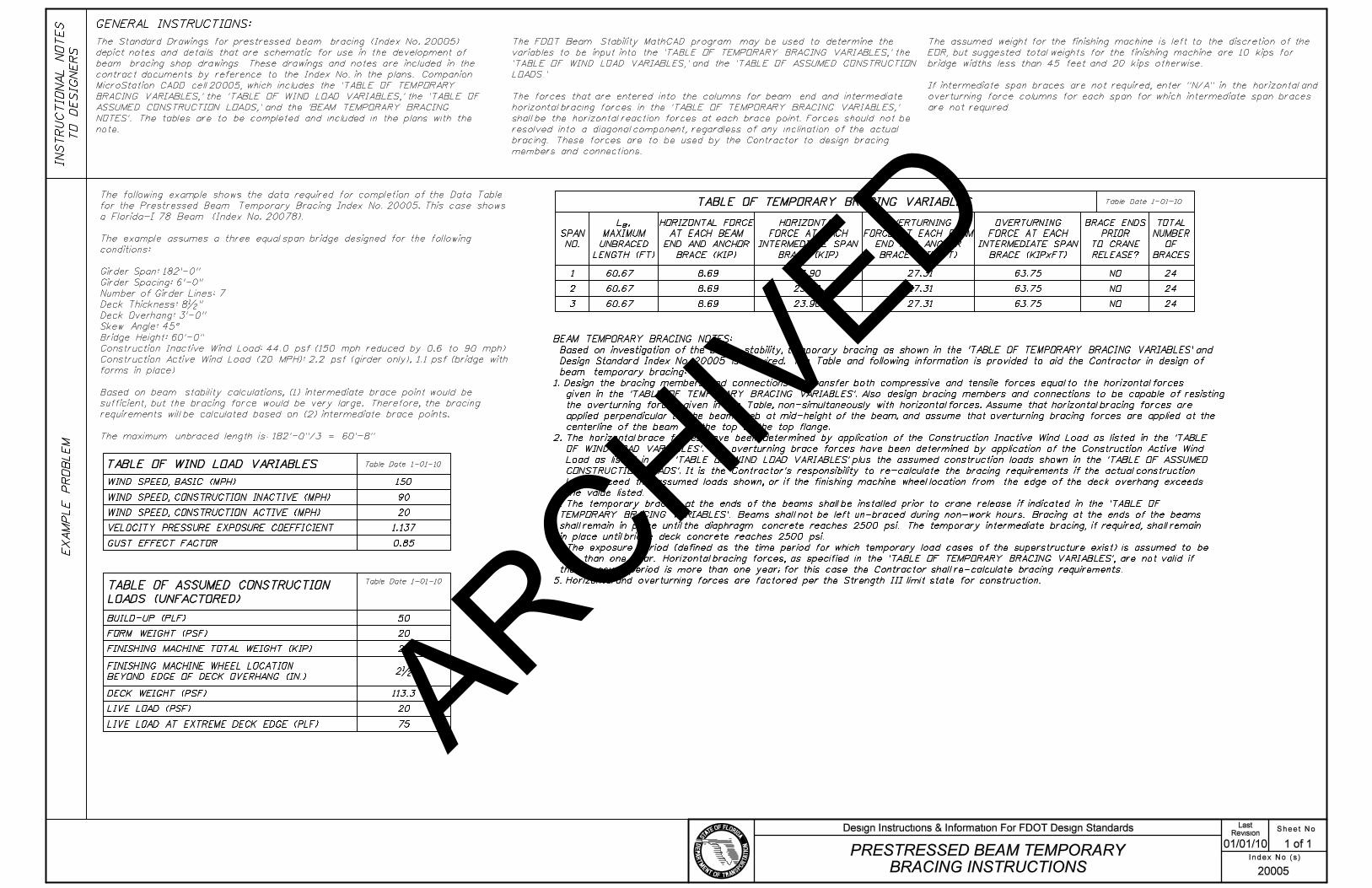
The Standard Drawings for prestressed beam bracing (Index No. 20005)
depict notes and details that are schematic for use in the development of
beam bracing shop drawings. These drawings and notes are included in the
contract documents by reference to the Index No. in the plans. Companion
MicroStation CADD cell 20005, which includes the ’TABLE OF TEMPORARY
BRACING VARIABLES,’ the ’TABLE OF WIND LOAD VARIABLES,’ the ’TABLE OF
ASSUMED CONSTRUCTION LOADS,’ and the ’BEAM TEMPORARY BRACING
NOTES’. The tables are to be completed and included in the plans with the
note.
The following example shows the data required for completion of the Data Table
for the Prestressed Beam Temporary Bracing Index No. 20005. This case shows
a Florida-I 78 Beam (Index No. 20078).
The example assumes a three equal span bridge designed for the following
conditions:
Girder Span: 182’-0"
Girder Spacing: 6’-0"
Number of Girder Lines: 7
Deck Thickness: 8�"
Deck Overhang: 3’-0"
Skew Angle: 45^
Bridge Height: 60’-0"
Construction Inactive Wind Load: 44.0 psf (150 mph reduced by 0.6 to 90 mph)
Construction Active Wind Load (20 MPH): 2.2 psf (girder only), 1.1 psf (bridge with
forms in place)
Based on beam stability calculations, (1) intermediate brace point would be
sufficient, but the bracing force would be very large. Therefore, the bracing
requirements will be calculated based on (2) intermediate brace points.
The maximum unbraced length is: 182’-0"/3 = 60’-8"
The FDOT Beam Stability MathCAD program may be used to determine the
variables to be input into the ’TABLE OF TEMPORARY BRACING VARIABLES,’ the
’TABLE OF WIND LOAD VARIABLES,’ and the ’TABLE OF ASSUMED CONSTRUCTION
LOADS.’
The forces that are entered into the columns for beam end and intermediate
horizontal bracing forces in the ’TABLE OF TEMPORARY BRACING VARIABLES,’
shall be the horizontal reaction forces at each brace point. Forces should not be
resolved into a diagonal component, regardless of any inclination of the actual
bracing. These forces are to be used by the Contractor to design bracing
members and connections.
The assumed weight for the finishing machine is left to the discretion of the
EOR, but suggested total weights for the finishing machine are 10 kips for
bridge widths less than 45 feet and 20 kips otherwise.
If intermediate span braces are not required, enter "N/A" in the horizontal and
overturning force columns for each span for which intermediate span braces
are not required.
BEAM TEMPORARY BRACING NOTES:
Based on investigation of the beam stability, temporary bracing as shown in the ’TABLE OF TEMPORARY BRACING VARIABLES’ and
Design Standard Index No. 20005 is required. The Table and following information is provided to aid the Contractor in design of
beam temporary bracing:
1. Design the bracing members and connections to transfer both compressive and tensile forces equal to the horizontal forces
given in the ’TABLE OF TEMPORARY BRACING VARIABLES’. Also design bracing members and connections to be capable of resisting
the overturning forces given in the Table, non-simultaneously with horizontal forces. Assume that horizontal bracing forces are
applied perpendicular to the beam web at mid-height of the beam, and assume that overturning bracing forces are applied at the
centerline of the beam at the top of the top flange.
2. The horizontal brace forces have been determined by application of the Construction Inactive Wind Load as listed in the ’TABLE
OF WIND LOAD VARIABLES’. The overturning brace forces have been determined by application of the Construction Active Wind
Load as listed in the ’TABLE OF WIND LOAD VARIABLES’ plus the assumed construction loads shown in the ’TABLE OF ASSUMED
CONSTRUCTION LOADS’. It is the Contractor’s responsibility to re-calculate the bracing requirements if the actual construction
loads exceed the assumed loads shown, or if the finishing machine wheel location from the edge of the deck overhang exceeds
the value listed.
3. The temporary bracing at the ends of the beams shall be installed prior to crane release if indicated in the ’TABLE OF
TEMPORARY BRACING VARIABLES’. Beams shall not be left un-braced during non-work hours. Bracing at the ends of the beams
shall remain in place until the diaphragm concrete reaches 2500 psi. The temporary intermediate bracing, if required, shall remain
in place until bridge deck concrete reaches 2500 psi.
4. The exposure period (defined as the time period for which temporary load cases of the superstructure exist) is assumed to be
less than one year. Horizontal bracing forces, as specified in the ’TABLE OF TEMPORARY BRACING VARIABLES’, are not valid if
the exposure period is more than one year; for this case the Contractor shall re-calculate bracing requirements.
5. Horizontal and overturning forces are factored per the Strength III limit state for construction.
ARCHIVED

B
SPAN
NO.
TABLE OF TEMPORARY BRACING VARIABLES
TOTAL
NUMBER
OF
BRACES
L ,
MAXIMUM
UNBRACED
LENGTH (FT)
TABLE OF WIND LOAD VARIABLES
WIND SPEED, BASIC (MPH)
WIND SPEED, CONSTRUCTION INACTIVE (MPH)
WIND SPEED, CONSTRUCTION ACTIVE (MPH)
GUST EFFECT FACTOR
DECK WEIGHT (PSF)
TABLE OF ASSUMED CONSTRUCTION
LOADS (UNFACTORED)
BUILD-UP (PLF)
FORM WEIGHT (PSF)
FINISHING MACHINE TOTAL WEIGHT (KIP)
LIVE LOAD (PSF)
LIVE LOAD AT EXTREME DECK EDGE (PLF)
YES/NO
YES/NO
YES/NO
YES/NO
VELOCITY PRESSURE EXPOSURE COEFFICIENT
FINISHING MACHINE WHEEL LOCATION
BEYOND EDGE OF DECK OVERHANG (IN.)
PRESTRESSED BEAM TEMPORARY BRACING DATA TABLES
Table Date 1-01-10
Table Date 1-01-10
Table Date 1-01-10
HORIZONTAL FORCE
AT EACH BEAM
END AND ANCHOR
BRACE (KIP)
HORIZONTAL
FORCE AT EACH
INTERMEDIATE SPAN
BRACE (KIP)
OVERTURNING
FORCE AT EACH BEAM
END AND ANCHOR
BRACE (KIPxFT)
OVERTURNING
FORCE AT EACH
INTERMEDIATE SPAN
BRACE (KIPxFT)
BRACE ENDS
PRIOR
TO CRANE
RELEASE?
BEAM TEMPORARY BRACING NOTES:
Based on investigation of the beam stability, temporary bracing as shown in the ’TABLE OF TEMPORARY BRACING VARIABLES’ and
Design Standard Index No. 20005 is required. The Table and following information is provided to aid the Contractor in design of
beam temporary bracing:
1. Design the bracing members and connections to transfer both compressive and tensile forces equal to the horizontal forces given in
the ’TABLE OF TEMPORARY BRACING VARIABLES’. Also design bracing members and connections to be capable of resisting the
overturning forces given in the Table, non-simultaneously with horizontal forces. Assume that horizontal bracing forces are applied
perpendicular to the beam web at mid-height of the beam, and assume that overturning bracing forces are applied at the centerline
of the beam at the top of the top flange.
2. The horizontal brace forces have been determined by application of the Construction Inactive Wind Load as listed in the ’TABLE
OF WIND LOAD VARIABLES’. The overturning brace forces have been determined by application of the Construction Active Wind
Load as listed in the ’TABLE OF WIND LOAD VARIABLES’ plus the assumed construction loads shown in the ’TABLE OF ASSUMED
CONSTRUCTION LOADS’. It is the Contractor’s responsibility to re-calculate the bracing requirements if the actual construction
loads exceed the assumed loads shown, or if the finishing machine wheel location from the edge of the deck overhang exceeds
the value listed.
3. The temporary bracing at the ends of the beams shall be installed prior to crane release if indicated in the ’TABLE OF
TEMPORARY BRACING VARIABLES’. Beams shall not be left un-braced during non-work hours. Bracing at the ends of the beams
shall remain in place until the diaphragm concrete reaches 2500 psi. The temporary intermediate bracing, if required, shall remain
in place until bridge deck concrete reaches 2500 psi.
4. The exposure period (defined as the time period for which temporary load cases of the superstructure exist) is assumed to be
less than one year. Horizontal bracing forces, as specified in the ’TABLE OF TEMPORARY BRACING VARIABLES’, are not valid if
the exposure period is more than one year; for this case the Contractor shall re-calculate bracing requirements.
5. Horizontal and overturning forces are factored per the Strength III limit state for construction.
ARCHIVED