Embed Size (px)
Citation preview
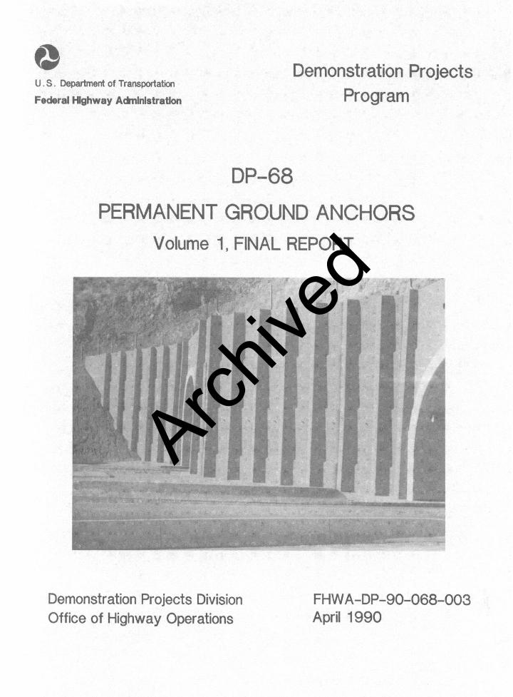
Demonstration Projects Division Office of Hiahway Operations
FHWA-DP-90-068-003 April 1990
Archive
d
Technical Report Documentation Page1. Repor t No . 2. Government Accession No. 3 . Reaplent’. Catalog N o .
FHWA-DP-90-068-003
4. Tit19 and Subt i t le 5 . Report Dote
DP-68 - Permanent Ground Anchors April 1990Volume 1, Final Report 6. Performing Organizat ion Code
HHO-42
7. Author’s)8. PerformIng Organizat ion Report NO .
Richard S. Cheney
9. Performing Organizat ion Name and Address 1 0 . Work Unit No. (TRAIS)HHO-3O/HHO-40Federal Highway Administration 11. Contract or Grant No.
400 Seventh Street, SW.LJashington, D.C. 20590 13. TYPO of Repor t ond Per iod Covered
12. sponsoring Agency Name and Address,
HHO-40 Final ReportFederal Highway Administration400 Seventh Street, SW. 14. Sponsoring Agency Code
Washington, D.C. 2059015. Supplementary Notes
FHWA: Theodore Ferragut
16. Abstract
Ground anchors, often called tiebacks, are structural elements which receive theirsupport in soil or rock and act to retain earth masses and/or applied structuralloads. The Federal Highway Administration recognized that the use of permanentground anchors in highway cut sections could affect substantial benefits in botheconomy and safety. The specific purpose of the permanent ground anchor demonstra-tion project was to introduce the concept of permanent ground anchor use intoAmerican construction practice. A manual numbered FHWA-DP-68-1R and titled"Permanent Ground Anchors" was prepared and several thousand copies distributed tohighway engineers. Permanent ground anchors on several projects were monitored tovalidate the concepts addressed in FHWA-DP-6%1R. This report summarizes theresults of both the field monitoring and the history of the permanent ground anchordemonstration project.
17. Kep W o r d s 18. Distr ibut ion Statamwtt
Permanent ground anchors, tiebacks, No restriction - NTISanchors, anchor specifications, anchortest projects, anchor acceptance criteria,anchor test procedures
19. Security Clarrif. (o f th is rap& 20. Security Clorrif. (of this pa901 21. No. of Po9.r 2 2 . Price
Form DOT F 1700.7 (a-72) Reproduction of complrtrd pagr autharizrd
i
Archive
d
Table of Contents
I. INTRODUCTION . . . . . . . . . . . . . . . . . . . . . . . . . . . . . . . . . . . . . . . . . . . . . . 1
II. DESCRIPTION AND BACKGROUND . . . . . . . . . . . . . . . . . . . . . . . . . . . . . . . . 3
III. PROJECT DEVELOPMENT....... . . . . . . . . . . . . . . . . . . . . . . . . . . . . . . . . 5
Resolution of Technical concerns . . . . . . . . . . . . . . . . . . . . . . . . . . 5
Cost-Effectiveness of Permanent Anchors................... 7
Permanent Ground Anchor Manual . . . . . . . . . . . . . . . . . . . . . . . . . . . . 8
Demonstration Project Accomplishments..................... 8
Continuing Developments in Permanent Anchors.............. 10
IV. DEMONSTRATION PROJECTS SUMMARY . . . . . . . . . . . . . . . . . . . . . . . . . . . . . 11
Widening of Existing Urban Interstate HighwayGeorgia I-75, Atlanta . . . . . . . . . ..*....................... 11
Repair of Urban Interstate Highway Retaining WallMaryland, I-95, Baltimore............................... 12
Pre-design Test Anchor ProgramWashington, I-90, Seattle . . . . . . . . . . . . . . . . . . . . . . . . . . . . . . . 15
Correction of LandsllideKentucky, KY-227, Carroll County.....,.................. 16
Lateral Support of Bridge End SlopesDimond Blvd - Anchorage, Alaska......................... 19
Urban Railroad Grade SeparationNorth Street Project, Lima, Ohio........................ 20
Tieback Bridge AbutmentRaw? Q, I-279, Pittsburgh, Pennsylvania................. 21
V. REHABILITATION OF STRUCTURES WITH PERMANENTGROUND ANCHORS.................. . . . . . . . . . . . . . . . . . . . . . . . . . . 21
Hope I Idaho Cemetery Wall Rehabilitation.................. 22
Nevada, Carlin Canyon Portal Rehabilitation............... 24
VI. CONCLUSIONS........ . . . . . . . . . . . . . . . . . . . . . . . . . . . . . . . . . . . . . . . 25
ii
Archive
d
APPENDIXLIST OF FIGURES
Figure Title Paae
1233A3B3c3D3E
Demonstration Presentations Completed A-lSimple Schematic of a Permanent Anchor A-2Georgia I-75 Project A-3Testing of First Anchor Row A-3Forming Concrete Wall Face Over Anchors A-3Final Wall, 1984 A-4Wall, 1988 A-4
44A4B4c4D4E5
SA,SB
Stable Roadway, 1988Above Wall-No Pavement CracksMaryland I-95 ProjectWall Joint Spalling, 1980Wall Base Translation, 1980TMD Anchors Installed, 1981Anchor TestingFinal Wall, 1984Washington I-90 ProjectAnchors Installed Through Existing
Cylinder Pile WallSC,SD Instrumentation for Anchor Testing
6 Kentucky Route 227 Project6A Embankment Stable With No Evidence of Movement
6B,6C6D
3 Years after ConstructionViews of Wall Face 4 Years After ConstructionTermite Infestation of Permanent Treated Wood
Face6E Blistering and Peeling of Protective Coating
on Waler A-137 Alaska Dimond Boulevard Project
88A,8B,8C8D,8E
8F8G,8H
99A9B9c
Completed Dimond Boulevard WallOhio Lima ProjectBuilding Underpinning OperationsAnchor DrillingFirst Level Anchors InstalledOpposing Views of Completed Walls, 1989Idaho Hope ProjectHope Wall Condition, 1980Close-up of Crack in Lower 12 feet of WallNew Reinforced Fascia Wall Poured Prior to
Anchor Installation9D Completed Anchored Wall Repair - 19819E Note Small Thickness of Wall Repair10 Nevada Carlin Canyon Project10A Completed West Portal, Carlin Canyon Tunnel
10BVertical Beams Contain Anchors A-22
Completed East Portal, Carlin Canyon Tunnel A-22
A-5A-6A-6A-6A-7A-7A-8A-9
A-9A-10A-11
A-11A-12
A-13
A-14A-15A-15A-16A-17A-18A-19A-19A-19
A-20A-20A-21A-22
iii
Archive
d
DP68 - final report
I. INTRODUCTION
Ground anchors, often called tiebacks, are structural elementswhich receive their support in soil or rock and act to retainearth masses and/or applied structural loads. Temporary groundanchor systems were introduced in the United States several yearsago to support excavations while the permanent facility wasinstalled. This temporary support system gained wide acceptancebecause of economic and safety aspects. However, Americanengineers hesitated to accept the permanency of ground anchors fora variety of reasons; particularly, a perceived lack of design andconstruction experience and documented design techniques.
The Federal Highway Administration (FHWA) recognized that the useof permanent ground anchors in highway cut sections could affectsubstantial benefits in both economy and safety. The economyresults from elimination of temporary support systems and reducedright-of-way considerations. Safety is improved by eliminatingcramped excavations cluttered with delicate bracing, and reducingthe time and area required for standard construction methods.Special benefits accrue in urban areas where adjoining facilitiesmust be supported during construction. Often the area saved byutilizing permanent ground anchors can eliminate the need forunderpinning nearby structures.
The specific purpose of the permanent ground anchor demonstrationproject was to introduce the concept of permanent ground anchoruse into American construction practice. A manual numberedFHWA DP-68-1R and entitled "Permanent Ground Anchors" was preparedand several thousand copies distributed to highway engineers. Themanual contains a comprehensive review of current design andconstruction methods. The recommended guideline procedures insurethat agencies adopting permanent ground anchors will follow a saferational procedure from site investigation to construction. Closeattention was given to presentation of suggested generalspecifications and plan details. These contract documents providethe transition from design analyses to field construction andfrequently decide the success or failure of new concepts such asthis. Every effort was made in these sample specifications toallow the experienced anchor contractor to use innovative methodsor equipment in construction. Such specifications are needed toencourage contractors to seek cost-effective improvements tocurrent anchoring methods.
The information in the DP-68-IR report was primarily based on:
1. existing technical literature on ground anchors,
2. reports from FHWA research projects performed from1979-82,volumes),
including FHWA/RD81/150 through 152 (3"Permanent Ground Anchors," and
FHWA/RD82/047, "Tiebacks," (reference copies of
1
Archive
d
DP68 - final report
which are available to the public from theNational Technical Information Service,Springfield, Virginia, 22161),
3. field inspections of permanent anchor projectsduring and after construction,
4. cooperative efforts between Federal and Stateengineers to prepare design calculations,and specifications for pilot test projects,
plans,
5. instrumentation of selected permanent anchors.
In 1984, formal presentations of the demonstration project weremade to public agencies. The presentation consisted ofhour segments,
four, l-
informationwhich introduced and briefly explained the detailed
contained in the manual. The object of thepresentations was to reach as many engineers as possible in ashort period of time to promote the concept ofanchoring.
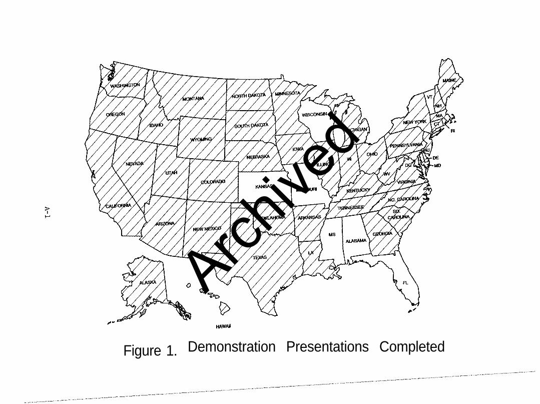
permanent groundOver 50 demonstration presentations were made in a
a-year period to engineers in 42 States. Figure 1 indicates theStates where presentations have been given. In-depth technicalassistance was then provided to highway agencies on a one-to-onebasis when specific projects arose. Currently, 31 States haveeither constructed permanently anchored structures, orhave permanently
currentlyanchored projects in design. Numerous
specialized presentations on construction,specification
inspection, orpreparation have also been completed.
on construction inspection has been prepared forA videotape
agencies.use by highway
During the demonstration presentations, several proposed highwayprojects with permanently anchored structures were identified ascandidates for instrumentation and performance monitoring.Cooperative Agreement Work Orders were issued to those agencies.The Work Orders provided a work plan and a schedule forreimbursement of funds necessary to instrument, monitor, andreport on the long-term performance of the permanently anchoredstructures. The period of5 years or less.
time for monitoring was generallyAccepted reports from five such demonstration
projects are included in the appendices of this report.
Coordination with technical groups has resulted in the preparationof standard specifications to nationally regulate the constructionof permanent ground anchor walls. In 1986, the PostInstitute published
Tensioning"Recommendations for Prestressed Rock and Soil
Anchors." More recently, Task Force 27, AASHTO, ARTBA and AGCJoint Committee, has prepared both a construction specificationand an inspector's manual for permanent ground anchors.and dissemination
Approval
1990.by AASHTO of both documents are anticipated in
2
Archive
d
DP68 - final report
II. DESCRIPTION AND EACKGRODND
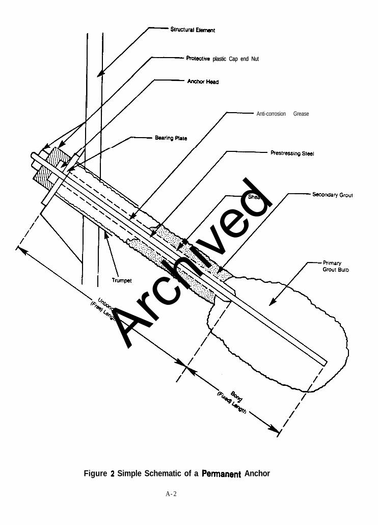
Within the past 20 years, many ground reinforcement techniqueshave been successfully introduced to American civil engineeringpractices after an extended period of use in Europe. The latestand possibly the most significant entrant is the permanent groundanchor. More precisely, the permanent ground anchor referred to. this report ' corrosion-protected, prestressed, cement-iiouted tendon whizfl rnty be installed in soil or rock. Verybroadly described, a ground anchor is a device which mobilizes andtransfers a resisting force from the ground to a structuralelement such as a wall or slab. Although similar in function andlooks, the permanent anchor, is not to be confused with thetemporary tieback or mechanical anchor or resin rock bolt. In theremainder of this report, the word "anchor" when used shall meanpermanent ground anchor unless otherwise specifically stated.Figure 2 shows a schematic of a typical anchor.
These anchors are generally inserted in a hole which is drilled ordriven into soil or rock. Certain basic anchor terms will now beintroduced which will be used throughout this report. Specificanchor details will be reserved for explanation in applicablesections.
Basic anchor components frequently referred to are:
1. The prestressinq steel --commercially available insingle or multiple wires, strands, or barscomprising:
a. the bond lenqth--that portion of theprestressing steel fixed in the primary groutbulb, through which load is transferred to thesurrounding soil or rock, and
b. the unbonded lenath--that portion of theprestressing steel which is free to elongateelastically and transmit the resisting forcefrom the bond length to the structural element(i.e., the wall face, etc.).
2. The anchorase--a device usually consisting of a plateand an anchor head (or threaded nut) which permitsstressing and lock-off of the prestressing steel.
3. The orout--a portland cement based mixture whichprovides corrosion protection as well as the mediumto transfer load dram the prestressing steel to thesoil or rock.
Anchors were introduced in the 1930s and, by the 196Os, were incommon use for major structures of all types.successful widespread
The keys touse in Europe were both social and
technical. The scarcity of land available for construction,
3
Archive
d
DP68 - final report
particularly in urban areas, required excavation and retentiontechniques that could be accomplished with minimum disturbance toland owners or the traveling public. Anchored walls substantiallyreduced the amount of land required for construction while alsoreducing the project cost. Equally as important was the assurancethat this technique was safe and could be easily controlled inconstruction. European engineers spent many years developing andrefining public design and construction codes for anchors. Basedon field experience and long-term observation, these codesguaranteed the safety of each anchor by requiring testing tobeyond proposed design loads. Continuing historical developmentnow relates mainly to refinement of corrosion protection systems,load transfer of anchor forces into the ground, the form oftension members, and grouting methods. In some countries, anchorcontractors must pass acceptance tests before being allowed toinstall anchors. These acceptance tests involve installing andexcavating, for government inspection, a large number of anchorsaccording to the prevailing code. The data from such tests,although very costly, has contributed much to the development ofanchor use worldwide.
Until the late 197os, the only common use of anchors in theUnited States was to support temporary excavations. Although theUnited States' first permanent soil anchor was installed inDetroit, Michigan, in 1961, relatively few public agencies hadincorporated anchors in major permanent structures as of theinception of this demonstration project. The reasons for thishesitancy were:
1. the scarcity of American anchor design and constructionexperience; i.e., how do we design it and who can wetrust to properly install it?
2. the concern of anchor permanency against long-termcorrosion or creep; i.e., how long will anchors last andsafely carry design loads?
3. the delineation of proper areas for cost-effectiveapplication; i.e., where and how many do we use?
4. the constraints of contracting procedures used by publicagencies; i.e., how do we insure quality from the lowbidder?
In 1979, FBWA Demonstration Projects Divisionauthorized project development
(FBWA-DPD)to begin on the permanent anchor
project. A project manager and a technical advisory committeewere appointed. A work plan wasanchor technology and
developed to study existinginstallations; determine areas where
additional work was needed; update existing technology; prepare abasic design manual; and solicit test installations on highwayprojects. The objective was to provide highway agencies withadequate knowledge to permit confident, routine use ofanchors.
permanent
4
Archive
d
DP68 - final report
III. PROJECT DEVELOPMENT
Resolution of Technical Concerns
A review of existing technical literature on anchors confirmedthat most work had been done by the Europeans. Unfortunately,little documentation of design methods for anchors was available.This information void was a direct result of how anchor work wascontracted for in Europe. Nearly all European anchoring is doneon a design-construct, turnkey basis by specialist firms who, inmany cases, are pre-qualified to do anchor work by the government.These firms have developed proprietary design and constructionprocedures which are not released even to their clients.
For successful introduction of anchors into the United States, thecontracting approach promoted by the demonstration project wouldneed to conform to the current competitive bid procedures used byState agencies. This approach required both general designguidelines and a detailed construction specification. A three-pronged path was chosen which involved initiation of research indesign aspects, field inspection of on-going permanent anchorconstruction projects, and development of an easy-to-understandyet comprehensive construction specification.
In 1980, two basic design questions remained to be answered beforethe demonstration project could proceed--documentation of bothtechniques to determine anchor capacity and longevity aspects ofboth anchor materials and bond strengths. The former question wasaddressed by awarding research contracts to three experiencedanchoring firms --Soletanche-Rodio, Nicholson, and Stump-Vibroflotation, who independently prepared design manualsrespectively numbered FHWA RD 81/150; 81/151; and 81/152. Eachmanual contained a detailed explanation of the firm's generaldesign procedure as well as three documented case historiesillustrating use of the design procedure and the computations fora test project provided by FHWA. Although each firm useddifferent analyses, the basic method of design was the same; i.e.,the critical failure surface was located and the bond zone of theanchor founded beyond the failure plane. Load testing of allinstalled anchors was considered an extension of design as nodesign method existed to reliably predict, from subsurface data,the exact bond zone dimensions necessary to safely carry aparticular anchor load. These two concepts provided the basis forthe current anchor design practice in the United States.
The longevity aspects were addressed by the Schnabel FoundationCompany in FHWA RD 82/047, "Tiebacks." In this publication,methods of corrosion protection for permanent anchors weredetailed and recommendations given as to their use. The creepbehavior of anchors was also thoroughly investigated. Specificrecommendations were presented for anchor testing procedures andacceptance criteria to insure long-term anchor load capacity atacceptable deflections. Lastly, contracting guidelines forpermanent anchor work were presented. Important concepts such as
5
Archive
d
DP68 - final report
pre-qualification of anchor contractors, performance-typespecifications, and shared design responsibility between owner andcontractor were recommended for reliable, cost-effective anchorwork.
In reviewing the uses of permanent anchors, the permanentlyanchored retaining wall application was by far the most common andeconomically attractive. A decision was made to concentrate thedesign section of the FHWA DP 68 manual on permanent anchor walldesign. The design procedure initially adopted for thedemonstration project relied heavily on concepts developed frombraced wall systems as well as the aforementioned researchefforts. In technical areas where conflicting observations ortheories could not be resolved, the design procedure chose themore conservative position. The rationale for this decision wasthat instrumentation of initial anchored wall installations wouldbe encouraged. Highway agencies could then compare actualmeasured parameters with assumed. As a database was developed,various parameters could be confidently changed to lessconservative values.
In 1979-80, concurrent with the above research efforts, the PostTensioning Institute formed an ad-hoc committee to revise theexisting guidelines for anchor use. The committee was composed ofanchor contractors, producers, consultants and users. Theresulting publication, "Recommendations for Prestressed Rock andSoil Anchors," printed in 1980 and revised in 1986, establishednational standards for design and construction of anchors. Thesestandards, which were written in a simple format, were adopted bymany private and public organizations as the basis for theirconstruction specifications. Much of the information in thispublication was used to develop the guideline permanent anchorspecification for the demonstration project.
The resulting construction specification, published in theFHWA DP-68 manual for permanent anchors, was a performance-basedspecification. This wJ?e of specification was a departure fromthe prescription-type specifications used by public highwayagencies on other highway items. The proposed anchorspecification contained some prescription verbiage to control thematerials used and certain basic construction operations.However, the contractor was permitted, with few constraints, tochoose and control the method of drilling, the tendon type, thedrilled hole diameter, the bond zone dimensions and the totalanchor length. The performance aspect was that the contractor wasresponsible to produce an anchor which would pass certainacceptance test criteria established in the specification beforereceiving payment for the anchor. In short, the contractor wasresponsible for determining anchor installation procedures toobtain a desired anchor capacity selected by the agency.
The key element in the performance specification was pre-qualification of the contractor who would perform the anchor work.Permanent anchoring was recognized by researchers, technical
6
Archive
d
DP68 - final report
groups r and construction inspectors to be a specialty type ofwork. Furthermore, successful introduction of permanent anchoringinto highway agencies depended on their first project being asuccess. Few agencies had any construction personnel who wereknowledgeable of proper permanent anchor construction techniques.Specifying a specialist would permit the construction personnel toobserve proper techniques and develop inspection expertise whichcould be used on later projects where the agency relaxed the pre-qualification criteria.
Cost-Effectiveness of Permanent Anchors
After technical concerns had been addressed to the satisfaction ofthe technical advisory committee, the permanent anchor technologywas ready to be disseminated. Early in the demonstration project,data had been collected from a few permanent anchor projects doneprior to 1980, which indicated the per-square-foot wall cost to bebetween $30 and $40. At that time, standard concrete retainingwalls in cut situations were averaging about $75 per square foot.However, the cost effectiveness of the design technique and theperformance specification approach needed to be demonstratedbefore promoting routine consideration of permanent anchor systemsnationwide to highway agencies. A review of cost data from a fewprivate and public anchor wall projects indicated a cost of about$45 per square foot of wall face. Two State highway agencies,Georgia and Maryland, were identified by FHWA regionalgeotechnical engineers as having projects in design which wereappropriate for a permanent anchor alternate design.
The project manager provided design computations, plans, andspecifications for an alternate anchorlocations.
wall design at bothIn Georgia,
the standard Georgiaboth the alternate anchor wall design andDOT retaining wall design were included in
the contract documents for the I-75 project with instructions thatcontractors were to bid one or the other. The final bidtabulation showed that seven ofsubmitted bids
the eight contractors who(including the low bidder) had selected the
alternate anchor wall design. The bid price for the anchor wallalternate was about $36 per square foot;($410,000) th
about 40 percent loweran either the "as bid" or Engineers' estimate for the
standard Georgia retaining wall. In Maryland, the estimated costof the anchor wall design was so much less than the standarddesign that the standard design was deleted from the contract.The "as bid" price for the anchor wall was aboutfoot; a savings
$36 per squareof approximately 40 percent ($461,335) over the
conventional design. Two anchor walls constructedState during
in Washingtonthe same time period had bid prices between $41 and
$44 per square foot.design
It was evident that a permanent anchor wallwas economically competitive with
currently in use for walls in cut.standard designs
Archive
d
DP68 - final report
Permanent Ground Anchor Manual
In 1984, FHWA-DPD published definitive recommendations in DP-68-1,"Permanent Ground Anchors," to answer those previously statedconcerns of public agencies who were hesitant to specify permanentanchors. This manual presented, in detail, all basic conceptsnecessary for a highway agency to incorporate permanent anchors ona project.investigation,
Chapters were included on application criteria, site
system design,principles of anchor design, anchored
specifications,load testing/stressing,
corrosion,
andpreparation of plans/
construction control. The manual wasorganized in a manner consistenthighway project.
with the phases of a typicalThe emphasis in the manual was on identifying
applications where anchors could be used successfully; providing arational, step-by-step procedure for producing a safe, Yet cost-effective design; and establishing basic construction controls toassure a quality final product. The final section of the manualcontained a sample problem and detailed numerical solution whichdemonstrated the use of the information presented in the precedingchapters.
As clearly stated in the abstract, the manual was not intended topresent state-of-the-art procedures, but rather to serve as anintroduction to basic anchoring concepts.present basic information in simple,
The objective was tostraightforward terminology
to provide the practicing highway engineer with adequate knowledgeto successfully contract for permanent anchor work.
Demonstration Project Accomplishments
The project accomplishments can be measured in terms of technologytransferred to highway agencies, number ofadopting permanent anchors
highway agenciesfor routine highway applications,
performance of anchor walls designed based on the guidelineprocedure, and cost effectiveness of permanent anchor designsnationwide.
Technology transferproject.
is an important element of any demonstrationPresentations of permanent ground anchor technology were
requested and completed in 42 States to over 3,800 engineers whilethe project was active. The project manual, "Permanent GroundAnchors," was reprinted three times due to heavy demand, withabout 5,000 copies being distributed nationally. The manual iscurrently available from the National Technical InformationService, Springfield, Virginia 22161, under accession number PB851780107/AS. In addition, about 500 copies of both the researchpublication "Tiebacks" (FHWA RD82/047) and the Post TensioningInstitute's "Recommendations for Prestressed Rock and SoilAnchors" were distributed nationally to highway agencies.
At the inception of the project, only three State highway agencieswere employing permanent ground anchors on construction projects.The project manager provided detailed technicalthose highway
assistance toagencies interested in alternate designs involving
8
Archive
d
DP68 - final report
permanent anchors. This assistance involved preparation oftypical design computations, specifications and plans for specificprojects, or review of consultant-submitted designs. At present,31 States are using permanent anchors; nearly all are using thedesign procedures outlined in the FHWA DP-68 "Permanent GroundAnchor" manual. All walls constructed using these designprocedures have performed satisfactorily after construction. Nowalls have failed to perform their design function, whether theproject involved restraint of adjacent buildings, highways orutilities. The design method has been proven to produce a stablewall system in a variety of imposed loading situations. The onlyquestion which remains to be answered by future observation andresearch is the degree of conservatism of the method. In theMarch 1988 reprinting of the "Permanent Ground Anchor" manual, theminor changes that were made to the example problem designprocedure were the result of observations of the performance ofrecently constructed anchor walls.
Interestingly, the cost effectiveness of permanent anchor walls,even those designed by the admittedly conservative, originalprocedure in the manual, far exceeds that of other possible walldesigns in cut situations. Other changes may result whenadditional research is completed and evaluated by highwayagencies.
Some highway agency engineers were reluctant to specify a newtechnology which did not have a history of use in their State. Toaddress these concerns and to stimulate highway agency interest inpermanent ground anchors, the Demonstration Projects Divisionoffered to provide funds for instrumentation and long-termevaluation of anchor walls. The objectives of the performanceevaluation were both to prove to the agency that permanent anchorsdid perform in the long term and to provide highway agencies withhard data which could be used to refine their design procedures.The 8 projects selected for construction monitoring cost $406,475to instrument and evaluate. The reported savings from 4 of theseprojects totaled nearly $20 million.
In the past 10 years, the total square footage of permanent anchorwalls being constructed has increased dramatically. The firstanchor wall projects were scattered geographically and involvedwall areas less than 20,000 square feet. Recent projects, such asI-215 in Salt Lake City, Utah; I-90 in Seattle, Washington; I-10in Phoenix, Arizona; and I-20 in Dallas/Ft. Worth, Texas, allinvolved wall areas greater than 100,000 square feet. Evenrelatively small anchor wall projects such as I-90 in Wallace,Idaho, and I-35 in Duluth, Minnesota, contained in excess of40,000 square feet of permanent anchor wall.
In 1989, 2 million square feet of anchor wall construction isprojected. Based on previously documented savings, this wall areause translates into a savings in excess of $70 million in 1989.
9
Archive
d
DP68 - final report
As highway agencies began adopting permanent anchor walls intoroutine project designs, the emphasis in the demonstrationprojects shifted to construction control. During 1986-88, theproject manager completed presentations to construction inspectorsin 15 States. These efforts were usually done at the project sitejust after construction had begun, both to determine which methodsthe contractor would use and to allow inspectors to identify areaswhere training should be focused. Frequently, the contractors'personnel were invited to attend these presentations to see theinspection procedures which would be used on the project.
Continuinc Develooments in Permanent Anchors
By design, the purpose of a demonstration project is to introducenew technology into routine use by highway agencies and establishnational guidelines for safe, cost-effective use of thetechnology. On October 1, 1988, those goals were judged by FHWAto have been fulfilled and subsequently the permanent groundanchor project was removed from active status. However, by thelatter stages of the project, involvement was sought of othertechnical groups within the highway community to control thefuture direction of permanent anchoring.
The AASHTO-AGC-ARTBA Joint Committee Task Force 27 on GroundModification was formed on the recommendation of FHWA. A groundanchor group has been formed within the Task Force to developfuture design and construction standards. The intent is toprovide AASHTO with standards for national distribution.Currently, three efforts are underway in the group. A permanentground anchor generic specification, a ground anchor constructioninspection manual, andwalls.
a design guide for build-down retainingThe specification has been approved by the Task Force and
sent to AASHTO for approval. The inspection manual and designguide were submitted to the Task Force for approval in early 1990.
The increase in permanent anchor use has generated many newquestions about anchor design and construction techniques.However, unlike the early research efforts for this project, thesequestions relate not to proving whether anchors work but torefinements to optimize current procedures. Highway agencies whohave adopted permanent anchors into routine construction practicehave initiated operational research which will lead to eitherimproved techniques or increased anchor usage.these efforts is
An example ofthe Washington State DOT study on seismic
response of tieback walls.expand anchor use into
The objective of this study is toseismically active areas
rational modifications toby developing
current static design procedures. Anupcoming major study, funded by FHWA's Office of Research in 1989,will focus on refinement ofsoil-structure interaction.
those design factors dealing withItems such as bond zone load transfer
factors, earth pressure distribution,expected to be analyzed.
and soldier pile design are
10
Archive
d
DP68 - final report
In regard to national standardization of anchor testingprocedures, the American Society of Testing Materials (ASTM) hasformed subcommittee D18.11. The goal of the subcommittee is toprepare an ASTM standard for tensile load testing of individualanchors. The standard will include details of the apparatus usedto apply and measure the load, the apparatus for measuringmovements, the loading procedure, safety requirements, andrecording of data. An appendix on proper presentation of testdata will be included.
Although FHWA's role in actively promoting permanent ground anchoruse has been phased out, the interaction during the precedingyears with other technical groups has insured continuing nationaldevelopment of anchor technology in the future. FHWA willcontinue to provide technical assistance on future anchor designsor technical reviews of new anchor technology. The role ofcontinued promotion and development rests now with the technicalgroups of the highway community.
IV. DEiMONSTRATION PROJECTS SUMMARY
One of the objectives of Demonstration Project No. 68 was toconvince highway agencies to monitor construction performance andlong-term behavior of permanent ground anchored structures. SevenStates participated, each application varying some degree from theother either in terms of soil conditions, anchored wall design, oranchor type. Detailed reports by the project's principalinvestigators of the results of instrumentation and interpretationof wall performance are included in the appendices of this report,except for the Pennsylvania DOT tied back abutment project whichwas only constructed in 1988. The following executive summary ofeach project highlights basic design and construction informationas well as the primary conclusions for each project.
Wideninq of Existinq Urban Interstate HiqhwavI-75, Atlanta, Georqia
The widening of I-75, which is in a cut section through downtownAtlanta, presented several major problems such as very limitedright-of-way, existing utilities and buildings, trafficmaintenance of 100,000 vehicles per day, and a short time-framefor construction. A permanent anchored wall design was selectedfor use in a critical area near 5th Street, where 30-foot highcuts would be required near existing facilities. The general soilconditions consisted of varying mixtures of micaceous sands andsilts over bedrock. These soils are frequently described assaprolite which denotes residual products of rock decompositionwhere deep rock weathering has occurred in a wet, humid climate.
Demonstration project funding for instrumentation, interpretation,and reporting on wall performance was provided in July 1981 toGeorgia DOT under a Cooperative Agreement. In turn, Georgia DOTcontracted with Law Engineering/Geoconsult International toperform most of the prescribed tasks in the Demonstration Project
11
Archive
d
DP68 - final report
Cooperative Agreement. The principal investigators wereMessrs. David Mitchell of Georgia DOT and Thomas Richardson of LawEngineering Consultants. A specialground
task, unique to this firstanchor demonstration project, was development by a
specialist of a basic,ground anchor systems.
reliable instrumentation plan for permanentThe intent was
evaluateto develop, install,
and, if successful, recommend this instrumentationpackage on future anchor installations. The instrumentationreport prepared by Mr. John Dunnicliff is attached to the GeorgiaI-75, Atlanta report in the appendix.
Figures 3A to 3E show three stages of construction of the anchoredwall including the finished product in 1984 and 1988. All visualobservations and instrument measurements confirm that the wall andanchors are performing as anticipated in design. Long-termmeasurements were taken on 60 vertical and horizontal surveypoints established on or behind the wall during construction. Themeasurements showed that the movements which occurred indicatedactive earth pressure conditions and ceased shortly afterconstruction was completed. The survey points still available forreading indicate no definable wall or ground movement has occurredsince 1983.
The measurement of anchor load in selected tendons has been doneperiodically since 1983, Three different instruments were used tomonitor load--load cells, rod telltales, and wire telltales.Strain gages were not used due to problems involving bothattachment to the prestressed strand tendon and the range ofexpected microstrains. Although erratic readings were noticed invarious instruments during construction, those instruments whichhave continued to function to the present indicate that the loadcarried by the anchors has remained relatively constant, with arange of only 3 kips. A few anchors stabilized at loads whichwere slightly higher or lower than the lock-off load,variance with
indicatingthe magnitude or distribution of assumed lateral
earth pressure at that location. These variations had no effecton wall performance.
SinceDOT has
completion of the I-75 anchored wall at 5th Street, Georgiacompleted permanent anchor walls on 12 other highway
projects in the Atlanta metropolitan area. The success ofpermanent anchor construction has caused Georgia DOT to routinelypermit alternate designs involving anchored walls on highwayprojects.
Reoair of Urban Interstate Hiqhwav Retainina WallI-95, Baltimore, Marvland
In 1974-75, a 900-foot long wall with a maximum height of about25 feet was built to retain an earth cut for Interstate 95. Asteep natural slope rose from the top of the wallMount Carmel Cemetery.
to the nearby
was toward the wall.The natural surface drainage of this area
In addition, the subsurface drainage fromthe temporary cut facewall.
indicated a groundwater flow toward theUnfortunately, during wall construction, a clay material
12
Archive
d
DP68 - final report
was placed as backfill for the wall, effectively preventing anydrainage. Over a 4-year period, the natural water surface behindthe wall rose from below the wall footing to within 1 foot of thebackslope surface. The hydrostatic pressure increase causedsubstantial movement of the wall. Spalling of wall joints andbase translation caused an upheaval of the I-95 pavement when thepassive resistance in front of the wall was exceeded (seeFigures 4A-4B). Slope inclinometers, which were installed shortlyafter movement began, showed the location of the active andpassive failure surfaces.
The State immediately installed horizontal drains to lower thewater level and temporarily stabilize the movement. Analysis ofthe structural condition of the wall disclosed no major planes ofweakness. A lateral earth pressure analysis disclosed thatadditional lateral assistance was required to establish anadequate minimum safety factor of 1.5 against future sliding. Themethod chosen for wall repair could neither disturb the groundbehind the wall nor infringe on the safe clearance distance to theI-95 pavement. The Interstate Division of Baltimore City, whichhad responsibility for design, selected a permanent anchor repairsolution.
The stability of each wall panel was determined by lateral earthpressure analysis for the worst hydrostatic condition. From thisanalysis, the additional amount of resisting force was computedfor each panel to ensure a 1.5 safety factor. The soil conditionsbehind the wall indicated that the anchors could safely develop adesign capacity of 50 tons. The number of anchors per panel wasdetermined by dividing the total additional required resistance ineach panel by the design anchor load of 50 tons and rounding itoff to the next whole number. The anchors were located at therequired resultant pressure point on each panel.
The specification for the permanent anchors contained a pre-qualification clause to ensure that only an experienced permanentanchor contractor was permitted to bid the work.
The performance-type specification also allowed the contractor tochoose the most appropriate anchor tme I dimensions, andinstallation procedure to achieve the required design load. Apatented anchor type known as TMD was selected by the contractoras the best method to achieve the design load in the project soils(see Figure 4C).
The TMD anchor has a substantial advantage over the other anchortypes installed in cohesive soils in that several stages ofgrouting and regrouting can be performed in each anchor to develophe required capacity. High pressure grouting in cohesive soilsmust be done with care as application of excessive pressures willfail the clay surrounding the bond zone, resulting in very lowanchor capacities.desired
All 98 anchors on this project achieved thetest capacity and were accepted (see Figure 4D). After
lockoff, all anchor heads were encapsulated with plastic, greased-
13
Archive
d
DP68 - final report
filled caps to prevent corrosion (see Figure 4E). The FHWA-DPDfunded monitoring equipment for the wall to assess long-termperformance of the permanent anchor solution. The final report,which is included in the appendix, indicates that wall movementhas stabilized and the anchors are performing successfully.
The benefits of performance-type specifications containing a pre-qualification statement were shown on this project. The work wasprofessionally and cost effectively completed within the allottedtime frame. The Interstate Division of Baltimore City projectengineer could not remember a project where better relationsexisted between the contractor and the State.
In December 1981, a Cooperative Agreement was signed with MarylandDOT to document wall behavior. The performance monitoring andreporting for the permanent anchor wall instrumentation were doneby the Schnabel Foundation Company with Messrs. David Weatherbyand Harold Ludwig as co-principal investigators. The installationand monitoring of slope movement and water levels at the wall sitewere handled for Maryland DOT by Messrs. Paul Wardenfelt of theInterstate Division of Baltimore City and David Martin of theBureau of Soils and Foundations, as co-principal investigators.
The data obtained from this instrumentation was significant inseveral aspects. The major concern for using anchors at this sitewas the presence of fine grained soils in the anchor bond zone.The anchor instrumentation verified that these soils could safelywithstand the required anchor loads without deflection. However,the selection of the proper anchor type played a significant rolein obtaining the necessary capacity. The performancespecification permitted the contractor to select the anchor typebest suited to the site soil conditions and load requirements.The TMD regroutable anchor which was selected proved to be boththe optimum anchor type for the site and of such a configurationthat instrumentation could be reliably installed.
Later, in preparation of a generic anchor specification, FHWAwould recognize that the anchor contractor was the mostknowledgeable to select the best anchor type for the projectconditions.
The analysis of the data from the project instrumentation showed agradual transfer of load from the front of the bond zone to themiddle and rear third of the bond length. Also, a short sectionof the grout column in front of the load zone was observed totransfer load to the soil. This pointed out the need to bothbegin the bond zone at an offset distance behind the assumedfailure surface and to require weak grout in the free stressinglength.
14
Archive
d
DP68 - final report
Long-term measurements of the deflection of the wall face indicateonly minor movements have occurred with the net effect that thewall has moved into the slope. This may be indicative ofconservatism in estimating the required force to stabilize theoriginal wall instability.
The instrumentation system employed for these anchors was the mostreliable of all the demonstration projects. A few generalobservations on the success of the instrumentation are:
0 The instruments were selected and installed by aspecialist instrumentation contractor.
o Although strand tendons were to be used in productionanchors, bar tendons were used in instrumented anchorsto optimize instrumentation reliability.
0 Duplicate instrumentation was placed on the bar tendonand TMD external tube to insure reliable datacollection.
Pre-desiqn Test Anchor ProqramI-90, Seattle, Washinqton
During the preliminary design phase of I-90 in Seattle,Washington, a review was made of the preliminary designs tosupport high cut slopes along the proposed alignment. Apreliminary cost-estimate of $24 million had been made forcylinder pile walls to retain these cuts. An alternate designusing permanent ground anchored walls estimated at $6 million hadbeen suggested, but concern existed about long-term anchorcapacity in the clay subsoils. To evaluate long-term performance,a pre-design $150,000 test anchor program was proposed. Theprogram was developed to establish design criteria andconstruction control procedures which would insure long-termanchor support in the project soils. In June 1983, a CooperativeAgreement was signed between the Demonstration Projects Divisionand Washington State to provide $50,000 in funds forinstrumentation of, and reporting on, test anchors installed inthe over-consolidated clay deposit at the project site.Washington State designated Mr. Robert Josephson as principalinvestigator and selected Mr. Garry Horvitz of Hart-Crowser andAssociates to be the co-principal investigator. The test anchorsite is shown in Figures SA-5D.
The test anchor program was designed to use anchor types andinstallation procedures which were common to permanent anchorconstruction in the Northwest. For that reason, a 12-inchdiameter, non-pressure grouted anchor was selected, although itwas generally agreed that higher pressure, regroutable anchorswould provide higher capacities at shorter lengths. Bar tendonswere used to facilitate instrumentation, although multiple barsneeded to be installed in the anchors which were tested to pulloutto insure tendon failure did not occur prior to soil bond failure.
15
Archive
d
DP68 - final report
The testing procedure was directed at establishing therelationship between anchor load and creep. Short bond lengthswould be used to permit determination of ultimate capacity withreasonably sized test equipment. Although temporary anchors inthese over-consolidated clays had been loaded to high values, itwas suspected that design loads based on short term pullout testswould be subject to excessive long-term movement. The basic testprocedure chosen was as described in detail in FHWA RD 81/150,which is based on the French Standards for permanent anchors. Theend result of these tests is to determine the "critical creeptension," i.e., load beyond which unacceptable creep occurs.
The testing confirmed the suspicion that the critical creeptension would be substantially less than the ultimate loadmeasured on the pullout test. In fact, the critical creep tensionwas one half of the ultimate load. Based on these results, theultimate bond stress between the grout bulb and the clay wasestimated and used to determine that the desired design load couldbe achieved in a reasonable bond length. The test anchors werelocked off at various percentages of the critical creep tensionand monitored for several years. The results of the monitoringwere that only minimal long-term creep was observed.
Several permanently anchored walls have been completed on I-90based on the results of this study. These walls are allperforming satisfactorily with no evidence of movement ordistress. Short-term testing procedures developed in the pre-design anchor test program were used in construction to verify thelong-term capacity of anchors on the I-90 project.
In summary, the use of a $150,000 test anchor program by theWashington DOT resulted in a savings of $18 million on I-90 aswell as providing valuable information for private projects, whichhave since been designed for permanent anchors in the over-consolidated clays in Seattle.
Correction of LandslideKY-227, Carroll County, Kentuckv
In 1983, the Geotechnical Section of the Division of Materials,Kentucky Department of Highways, was involved in the design of alandslide stabilization on KY-227. The landslide, which had beenactive for several years, affected about 400 linear feet ofroadway. Solutions to the problem were limited as the roadwaylocation was bounded by a marginally stable, uphill slope and arailroad located downhill from the road. The 25-foot depth to theslide surface ruled out shear key construction or removal of poormaterials while the use of horizontal drains only increased thesafety factor to 1.1. The application was well suited for apermanent ground anchor solution, but the Department had notdesigned and let a permanent anchor project at that time. TheDepartment was concerned about employing this new technology at asite where an on-going landslide required permanent stabilizationin a short time period.
16
Archive
d
DP68 - final report
The solution was to adopt a shared responsibility design-constructapproach to a permanent ground anchor design. The Department'sgeotechnical engineers progressed borings, performed lab tests,selected soil strength values, and performed stability analyses todetermine the resisting forces required to stabilize thelandslide. A unique specification was developed to permitalternate permanent ground anchor solutions to be designed byqualified anchor firms. Specific experience requirements werelisted for the anchor design firms. Interested firms wererequired to submit detailed designs to the Department for approvalwithin a given time-frame before the project was bid. TheDepartment provided a package of geotechnical information, theresultant force to be resisted by the anchor wall, and specificstructural design requirements for the anchor wall design. Thesubmitted designs were required to include complete designcalculations, detailed construction drawings, and any specialnotes or specifications needed to supplement the Department'ssubmittal. Each firm's calculations were to be presented clearlyso that engineers unfamiliar with permanent anchor walls couldreview the information in a short time.
The Department formed an internal review board consisting ofstructural, geotechnical, and construction engineers to study thesubmitted designs. These initial reviews were very timeconsuming, particularly because different anchor firms useddifferent design methods to achieve a final anchor wall system toresist the given force.
The board realized that the original design criteria supplied tothe contractors needed to be clarified to permit all alternatedesigns to be prepared on a common basis. Items such as thedesign pressure diagram to be resisted, the use of wall frictionin the soldier pile design, drainage requirements, and the designprocedure for wood logging were redefined. The specialtycontractors were requested to revise their original designs andre-submit. The re-submitted designs were reviewed by the board ina short period of time and the project let on schedule. Althoughcertain other deficiencies in the construction specifications werefound after contract award, the project proceeded smoothly tocompletion.
Kentucky benefited from their contracting approach to this projectin several ways. One, they did not possess the in-house expertiseto design a permanent anchor wall before this project. The prebiddesign approach permitted exposure to several different wallconcepts and design philosophies. After completion of anothersimilar permanent anchor wall by the prebid method, Kentuckybelieves sufficient in-house design knowledge exists to permitassumption of some design details and use of a performancespecification which would permit post bid alternates.
17
Archive
d
DP68 - final report
Secondly, the use of a pre-qualification requirement for thepermanent anchor design and construction insured that onlyexperienced permanent anchor specialty firms would be eligible forthis work. This minimized the amount of construction inspectionnecessary to obtain a quality product. Kentucky inspectors wereable to observe the specialist contractor's methods, qualitycontrol procedures, and equipment in order to develop confidentinspection techniques for future projects.
Thirdly, the prebid specification is a good vehicle to implementthe cost-effective technology of permanent anchoring on publicprojects. The agency establishes the basic design framework andpermits several experienced contractors to compete for the mostcost-effective design.
The Carroll County wall (and a subsequent anchored wall inCampbell County) has been a successful use of permanent anchors tostabilize a landslide. The instrumentation indicated that byNovember 1985, movement of the wall and highway had virtuallystopped.
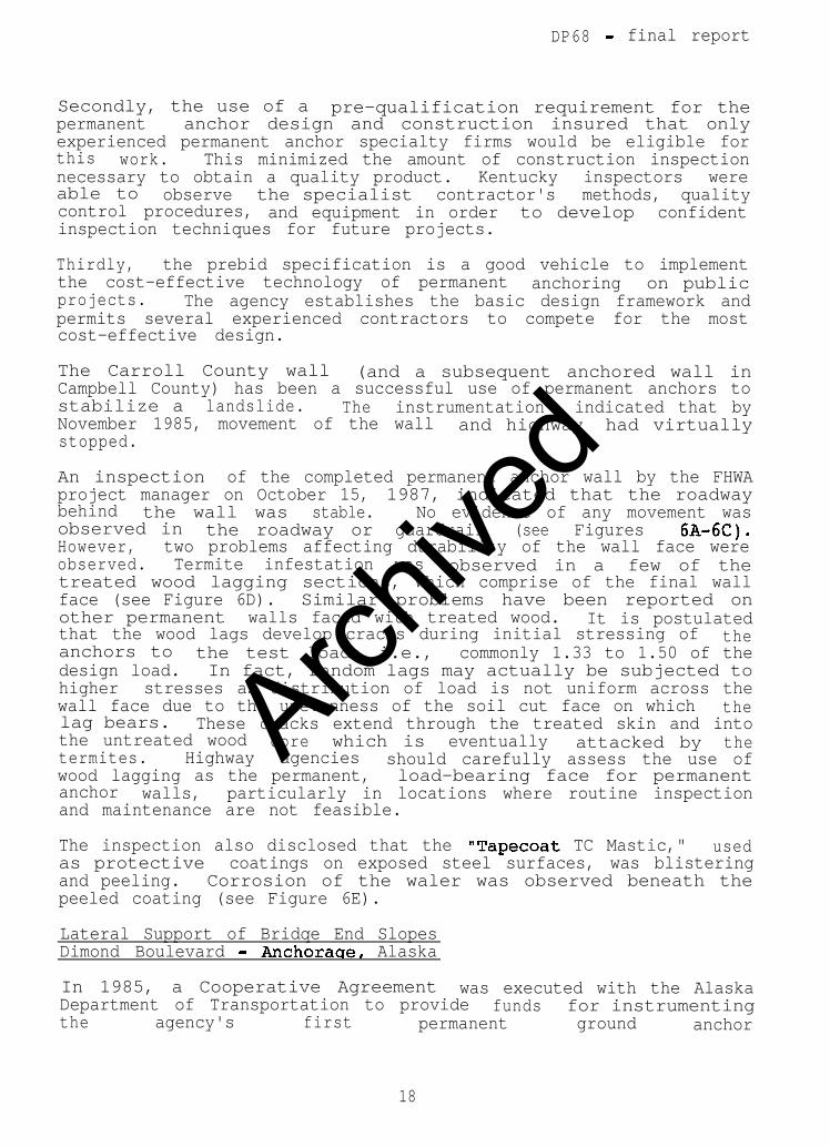
An inspection of the completed permanent anchor wall by the FHWAproject manager on October 15, 1987, indicated that the roadwaybehind the wall was stable. No evidence of any movement wasobserved in the roadway or guardrail (see Figures 6A-6C).However, two problems affecting durability of the wall face wereobserved. Termite infestation was observed in a few of thetreated wood lagging sections, which comprise of the final wallface (see Figure 6D). Similar problems have been reported onother permanent walls faced with treated wood. It is postulatedthat the wood lags develop cracks during initial stressing of theanchors to the test load; i.e., commonly 1.33 to 1.50 of thedesign load. In fact, random lags may actually be subjected tohigher stresses as distribution of load is not uniform across thewall face due to the unevenness of the soil cut face on which thelag bears. These cracks extend through the treated skin and intothe untreated wood core which is eventually attacked by thetermites. Highway agencies should carefully assess the use ofwood lagging as the permanent, load-bearing face for permanentanchor walls, particularly in locations where routine inspectionand maintenance are not feasible.
The inspection also disclosed that the "Tapecoat TC Mastic," usedas protective coatings on exposed steel surfaces, was blisteringand peeling. Corrosion of the waler was observed beneath thepeeled coating (see Figure 6E).
Lateral Support of Bridqe End SlopesDimond Boulevard - Anchoraqe, Alaska
In 1985, a Cooperative Agreement was executed with the AlaskaDepartment of Transportation to provide fundsthe
for instrumentingagency's first permanent ground anchor
18
Archive
d
DP68 - final report
installation. The project involved construction of an anchoredwall to support the existing end fills and abutments on the DimondBoulevard project in Anchorage. Traffic would be maintained onthe existing structure during construction. These walls wereunique in that resistance had to be provided for both vertical andlateral loads from the abutments which were supported on spreadfootings located above the wall in the end fill. The walls wererequired because the under road, Dimond Boulevard, was beingwidened and lowered to provide increased clearance under theexisting structure. The principal investigator was Mr. ThomasMoses of Alaska DOT.
Installation of soldier piles beneath existingproblems,
structures posesparticularly when
than the availablethe pile length required is greater
clearance. The solution used forinstallation
pilewas to close one lane to traffic on the existing
bridge, drill holes in the deck between girders, and install thepiles through the deck to the designed embedment into the ground.After completion of the pile installation in one lane, the pilesare cut off below deck level, the holes sealed, and trafficrestored in that lane while the operation begins in the next lane.The total time for installation of all piles was less than 1 weekusing this method.
One unexpected problem about these holes arose during constructionwhen an extremely heavy rain occurred. The drainage from the deckentered a few open holes and poured down on one end slopeerosion and
causingsettlement of one abutment. A solution to this
problem is to require deck holes to be temporarily sealed againstwater infiltration immediately after drilling and permanentlysealed immediately after the soldier beam is installed.
The anchors were installed intofill at levels
the existing granular approachbelow the existing abutment footing.
vertical and horizontal clearance existed for the anchorAdequate
operation such that trafficdrilling
could be maintained on DimondBoulevard when required during the construction.
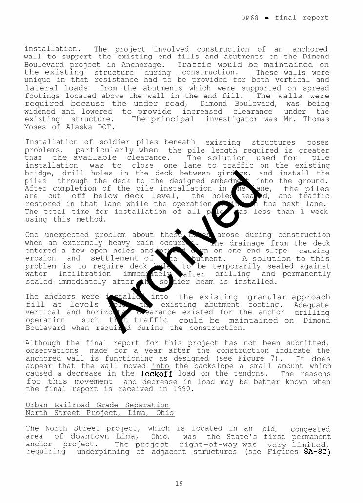
Although the final report for this project has not been submitted,observations made for a year after the construction indicate theanchored wall is functioning as designed (see Figure 7). It doesappear that the wall moved into the backslope a small amount whichcaused a decrease in the lockoff load on the tendons. The reasonsfor this movement and decrease in load may be better known whenthe final report is received in 1990.
Urban Railroad Grade SeparationNorth Street Project, Lima, Ohio
The North Street project, which is located in an old, congestedarea of downtown Lima, Ohio, wasanchor project. The project
the State's first permanent
requiringright-of-way was very limited,
underpinning of adjacent structures (see Figures 8A-8C)
19
Archive
d
DP68 - final report
as part of the permanent anchor wall construction. Only smallwall movements could be tolerated due to the proximity of thestructures to the wall. In addition, the bond zone soils werepredominately fine-grained with respective liquid limits andplastic indices generally above 30 and 15. These soils are at thelower end of soil types which are considered suitable forpermanent ground anchors.
In late 1985, a Cooperative Agreement was executed between FHWAand the State of Ohio to provide funds for monitoring theperformance of permanent anchors on this project. The co-principal investigators were Mr. Richard Engel of Ohio DOT andMr. Mark Lockwood of the H. C. Nutting Company, consultants forthis project.
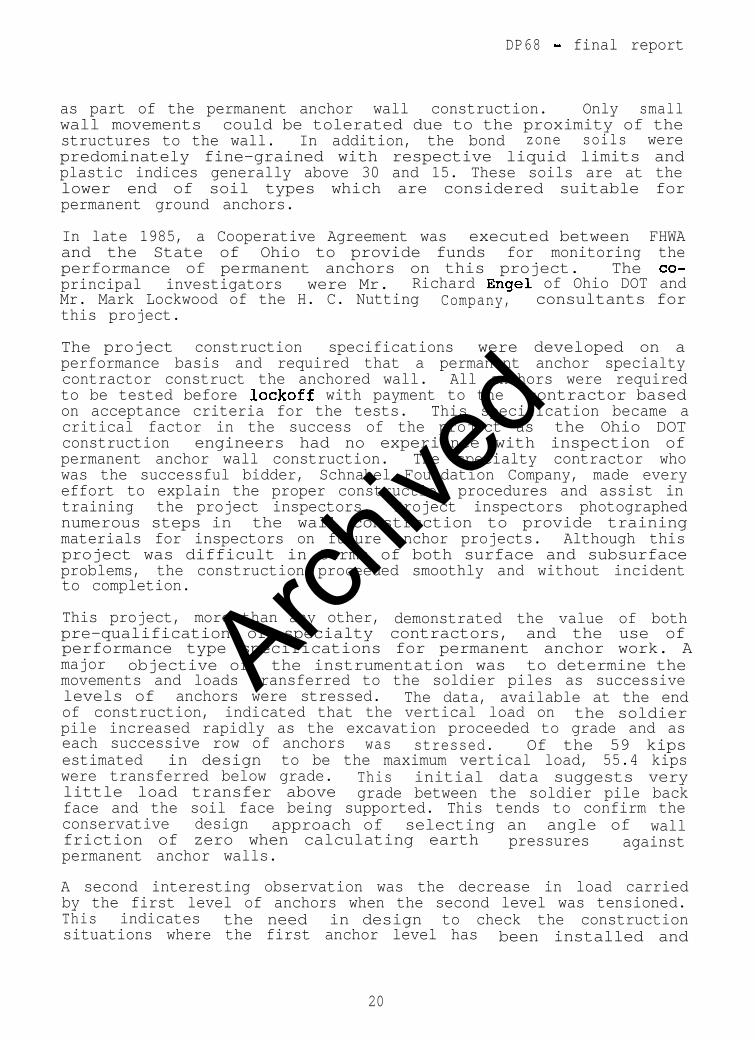
The project construction specifications were developed on aperformance basis and required that a permanent anchor specialtycontractor construct the anchored wall. All anchors were requiredto be tested before lockoff with payment to the contractor basedon acceptance criteria for the tests. This specification became acritical factor in the success of the project as the Ohio DOTconstruction engineers had no experience with inspection ofpermanent anchor wall construction. The specialty contractor whowas the successful bidder, Schnabel Foundation Company, made everyeffort to explain the proper construction procedures and assist intraining the project inspectors. Project inspectors photographednumerous steps in the wall construction to provide trainingmaterials for inspectors on future anchor projects. Although thisproject was difficult in terms of both surface and subsurfaceproblems, the construction proceeded smoothly and without incidentto completion.
This project, more than any other, demonstrated the value of bothpre-qualification of specialty contractors, and the use ofperformance type specifications for permanent anchor work. Amajor objective of the instrumentation was to determine themovements and loads transferred to the soldier piles as successivelevels of anchors were stressed. The data, available at the endof construction, indicated that the vertical load on the soldierpile increased rapidly as the excavation proceeded to grade and aseach successive row of anchors was stressed. Of the 59 kipsestimated in design to be the maximum vertical load, 55.4 kipswere transferred below grade. Thislittle load transfer above
initial data suggests verygrade between the soldier pile back
face and the soil face being supported. This tends to confirm theconservative design approach of selecting an angle of wallfriction of zero when calculating earth pressures againstpermanent anchor walls.
A second interesting observation was the decrease in load carriedby the first level of anchors when the second level was tensioned.This indicates the need in design to check the constructionsituations where the first anchor level has been installed and
20
Archive
d
DP68 - final report
excavation has proceeded to below the second anchor level. Insome cases, this stage will produce the maximum load to which thelevel one anchors will be subjected.
Two other points of interest are the relatively large cyclicmovements in both north-south wall deflection and the temperaturerange noted 15 feet behind the wall. Movements of 0.2 inchesappear to have occurred in channel number 93 between winter andsummer. Detailed temperature measurements of the soil both behindthe wall and in the anchor bond length were taken.
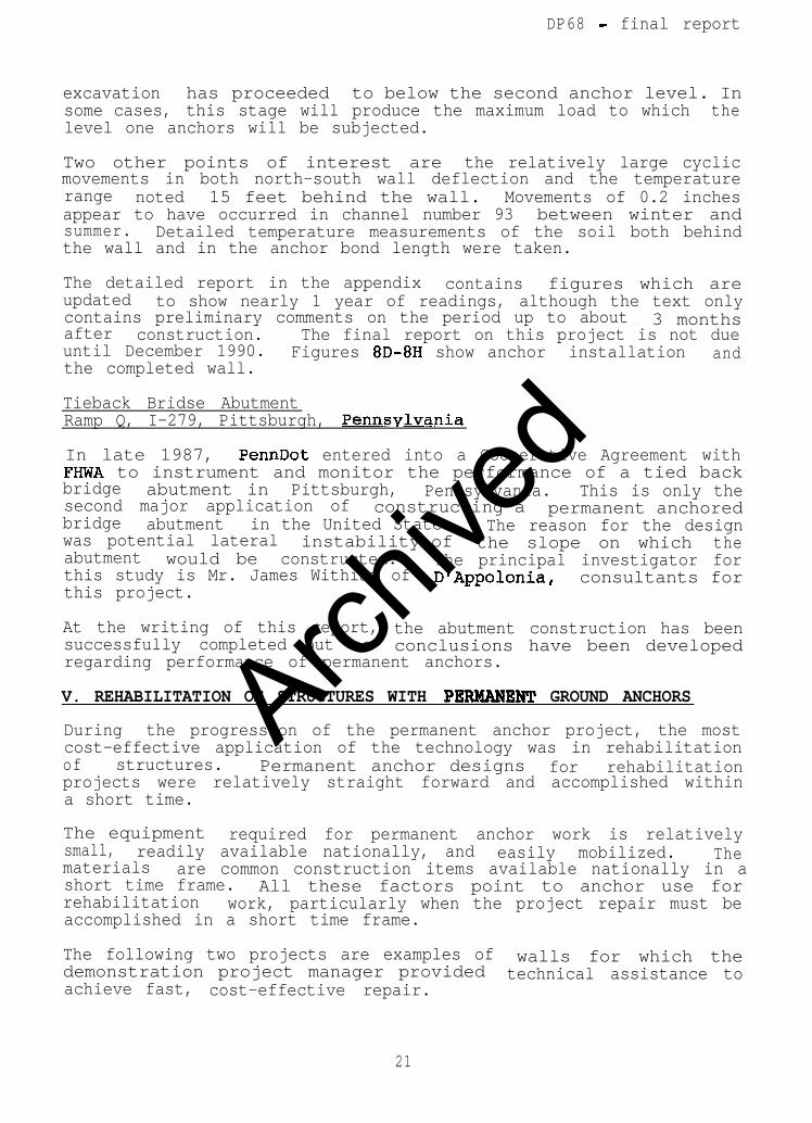
The detailed report in the appendix contains figures which areupdated to show nearly 1 year of readings, although the text onlycontains preliminary comments on the period up to about 3 monthsafter construction. The final report on this project is not dueuntil December 1990. Figures 8D-8H show anchor installation andthe completed wall.
Tieback Bridse AbutmentRamp Q, I-279, Pittsburgh, Pennsvlvania
In late 1987, PennDot entered into a Cooperative Agreement withFHYWA to instrument and monitor the performance of a tied backbridge abutment in Pittsburgh, Pennsylvania. This is only thesecond major application of constructing a permanent anchoredbridge abutment in the United States. The reason for the designwas potential lateral instability of the slope on which theabutment would be constructed.this study is Mr. James Withiam of
The principal investigator forD'Appolonia, consultants for
this project.
At the writing of this report, the abutment construction has beensuccessfully completed but no conclusions have been developedregarding performance of permanent anchors.
V. REHABILITATION OF STRUCTURES WITH PERM2XNENT GROUND ANCHORS
During the progression of the permanent anchor project, the mostcost-effective application of the technology was in rehabilitationof structures. Permanent anchor designs for rehabilitationprojects were relatively straight forward and accomplished withina short time.
The equipmentsmall,
required for permanent anchor work is relativelyreadily available nationally, and
materialseasily mobilized. The
are common construction items available nationally in ashort time frame.rehabilitation
All these factors point to anchor use forwork, particularly when the project repair must be
accomplished in a short time frame.
The following two projects are examples of walls for which thedemonstration project manager provided technical assistance toachieve fast, cost-effective repair.
21
Archive
d
DP68 - final report
Hope, Idaho, Cemetery Wall Rehabilitation
A 34-foot high by 200-foot long retaining wall was built in 1975to preserve a pioneer cemetery located above the proposed gradejust west of Hope, Idaho. The wall was designed with a flexibleface of precast reinforced concrete segments (stretchers)interconnected by vertical steel rods. Lateral support of theflexible panels was achieved in the lower 12 feet with rock bolttiebacks, in the middle 8 feet by gravity wall design, and theupper 14 feet by deadman anchors. Following construction, thestretchers began to crack and spa11 and the face began to tilt. Astudy of wall conditions in 1978-79 concluded that interaction ofthe vertical rods and reinforcing steel of the stretchers wascausing the reinforcing steel to break out of the stretchers inthe lower 12 feet of the wall (see Figures 9A-9B).
It was recommended that the wall be strengthened in this sectionand that long-term corrosion of unprotected steel wall elements beconsidered in the rehabilitation.
The FHWA Western District Federal Division was assignedresponsibility for the wall repair. The remedial treatment had toaccomplish several objectives:
0 not distress the delicate structural stability of theexisting wall or disturb the cemetery,
0 maintain a safe minimum clearance distance from thehighway,
o provide long-term corrosion resistance,
o be cost-effective.
Fortunately, subsurface conditions at the site were adequatelydefined by the site geology and records of the existing rock boltinstallation. The subsurface conditions consisted of a mixture ofsand, silt, and rock fragments overlying rock at relativelyshallow depths. Concerns for long-term corrosion and the need toreinforce the existing wall with minimal disruption to the site,combined with favorable subsurface conditions, led to a permanentground anchor solution.
The permanent anchor design was complicated by the delicatecondition of the existing wall face. Normally, the anchors wouldbe drilled through the wall and then stressed against the existingwall face to above design load. However, the thin wall face couldnot withstand any concentrated load. The available clearance tothe adjacent roadway allowed placement of a 16-inch thickreinforced concrete face over the bottom 12 feet of the existingface. Although this thickness was adequate to distribute theanchor design load over the face area, test stressing the anchorsto above design load on this new face was not deemed prudent.
22
Archive
d
DP68 - final report
Since the wall length was short, an alternate testing procedurewas used whereby two pre-production anchors would be performancetested to over 200 percent of design load against the naturalground just beyond the ends of the wall. After successful testswere performed, the contractor was required to install theproduction anchors with the same materials and procedures used forthe pre-production testing. Drainage that was occurring throughthe existing gapped wall face was designed to be carried by pipesplaced through the new solid wall face (see Figures 9C-9E).
The production anchors were bid on a "per-ft-of-anchor-installed"basis rather than the more common per-anchor basis because it wasimpossible to proof test each installed anchor. It was alsonecessary for the designer in this case to assume fullresponsibility for establishing a guaranteed "safe" anchor.Therefore, the anchor hole diameter, grout pressure, drillingprocedure, free length, and bond length were specified in theplans. Normally, the contractor would bid on a per-anchor basis;determine all anchor dimensions except minimum, free, and bondlengths; and prove the design load could safely be held by testingeach anchor. In this project, the production anchors werestressed to a 25-kip lockoff load. The measured movement of allanchors at that load was within the acceptable limits establishedfrom the pre-production test anchors.
The contract time for construction was 90 days, which would havebeen met except for some unexpected weather conditions. The twopre-production performance test anchors were installed at a bidprice of $1,500 each. The approximately 1,900 feet of productiondrilling and grouting was completed for the 61 wall anchors, whichwere double corrosion-protected l-inch diameter bars. The bidprice per linear foot of production anchor was $30 versus anestimated actual cost per foot of $25 by the contractor.
Based on the success of this project, it appears that permanentanchors can be successfully used as an alternate method of repairfor other thin-faced walls such as metal bin or concrete cribbing.
Nevada, Carlin Canyon Portal Rehabilitation
The portal walls of the Interstate 80 Carlin Canyon Tunnel inNevada were built in the 197Os, using a unique lateral supportsystem. Galvanized steel tie rods were fixed into the concretewall face and extended back to anchors in the nearby rockThese
slope.rods were designed to resist the lateral pressure generated
by the backfill that was subsequently placed. However, after8 years of service, one of the portal walls began to move outwardat an excessive rate. To stop this movement, the State removedthe backfill from the failing wall sections. The tie rods thatwere unearthed during backfill removal failed due to severecorrosion, particularly near the wall-rod interface. A closerexamination showed active corrosion on all parts of the galvanizedrods. As conditions were similar behind all other wall panels,
23
Archive
d
DP68 - final report
any remedial design selected would have to apply to all panels.The choices were to reconstruct the walls or re-establishpermanent lateral support for the existing walls. The State DOTselected permanent anchors to provide the required lateral supportto the existing walls.
Two problems were overcome in the permanent anchor design. First,the thickness of the existing wall was inadequate to support anddistribute the required permanent anchor loads (45 to 70 tons peranchor). This problem was resolved by casting vertical concretebeams at specified center-to-center distances along the panels.The 1 3/8-inch diameter single-corrosion-protected bar anchorswere placed through and stressed against the beams, which wereadequately reinforced to sustain the stressing load and distributethe force over the panel height. The second problem only occurredat panels where the backfill had been removed. Permanent anchorsare normally post-tensioned to the required proof load afterinstallation. However, passive resistance behind the excavatedpanels was insufficient to allow stressing the anchors to the testloads without damaging the wall. In addition, backfill should notbe placed and compacted around anchors that have previously beeninstalled. Backfill compaction operations can damage thecorrosion protection of the permanent anchor and can cause bendingof the tendon free length under the compactive load. Such abackfill procedure was used in the original portal constructionand reportedly caused inward wall deflections due to bending ofthe rods.
To prevent these problems, the State required backfill to beplaced in stages and compacted behind those wall panels to about3 feet above each successive row of anchors. The anchors in eachlower row were stressed and locked off before the backfill wasplaced to the next higher row. No attempt was made to pull thedeflected wall back to its original position for fear ofstructurally damaging the panels. Drainage was reestablishedbehind the excavated panels by handing vertical drains down theback face and connecting them to a positive outlet beforebackfilling.
The specification for the anchors was performance based; i.e., apre-qualification statement was included to ensure the work wasawarded only to an experienced permanent anchor contractor. Thecontractor was responsible for determining the actual requiredanchor bond length to develop adequate load capacity to satisfyanchor testing requirements for the design loads on the plans.
Within the specification, the contractor was allowed to use hisexpertise to determine tendon type f drilling method, groutingpressures, multiple grouting techniques, and bond lengthvariations to produce the most cost-effective anchor. The Stateaccepted or rejected each anchor on the results of eitherperformance or proof tests that were done on the installedanchors. The 64 anchors were bid on a per-unit basis at anaverage cost of $2,800, which included labor, materials, drilling,stressing, and testing. The actual anchor work was completed
24
Archive
d
DP68 - final report
within 3 months. The entire project, from design throughconstruction, took about 18 months. The final wall is shown inFigures 10A and 10B.
VI. CONCLUSION
The objective of Demonstration Project No. 68 was to introduce,nationally, the concept of permanent ground anchor use intoroutine construction practice. This objective has beenaccomplished through a multi-dimension program of research,technology transfer, technical assistance, and interaction withboth public and private organizations involved in permanentanchoring. As documented in the text of this report, the volumeof permanent anchor work in the United States is multiplyingyearly. State highway agencies are now considering anchors asroutine alternatives to conventional techniques rather than asresearch objects.
Although the Demonstration Project has ended, the mechanism is inplace for further refinement and promotion of permanent anchortechnology. Organizations such as AASHTO, AHTBA, AGC, ASTM, andthe Post Tensioning Institute have on-going committees studyingpermanent ground anchor standards and applications. Furthermore,FHWA and other government organizations are advancing programs forresearch to optimize the design procedures now in common use.
25
Archive
d

Archive
d
HAWAII
Figure 1. Demonstration Presentations Completed
Archive
d
b3tective plastic Cap end Nuthotective plastic Cap end Nut
Anti-corrosion Grease
Figure 2 Simple Schematic of a Pemranent Anchor
A-2
Archive
d
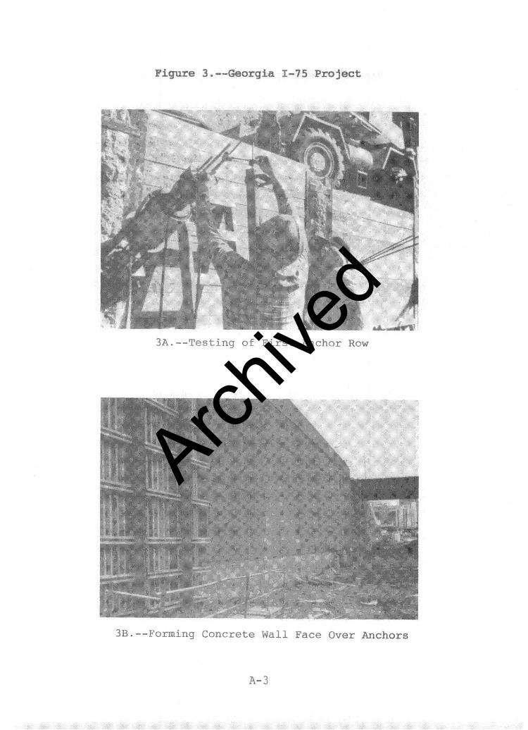
Figure 3. --Georgia f-75 Project
3A.--:Pesting 0: I'irst Anchor ROW
3B.--Forming Concrete Wall Face Over Anchors
A-3
Archive
d
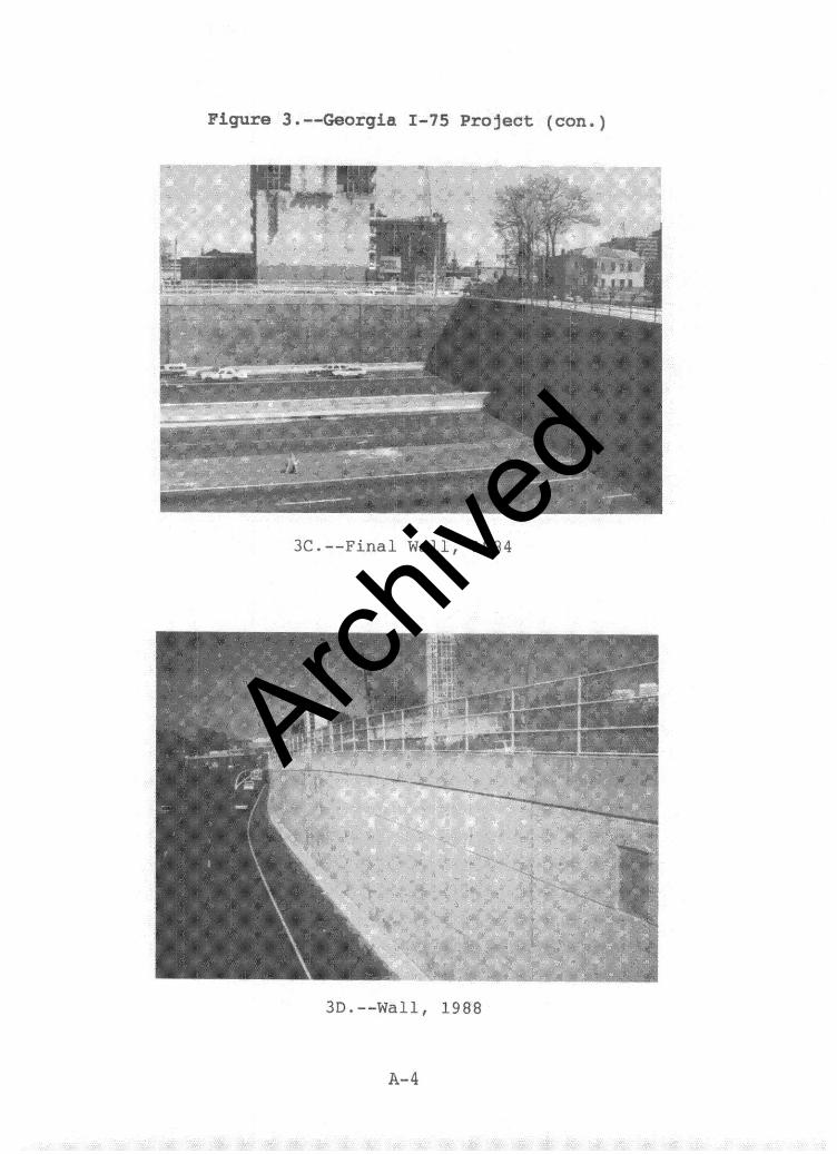
Figure 3 .--Georgia I-75 Project (con.)
3C.--Final Wall, 1984
:, _
3D.--Wall, 1988
A-4
Archive
d
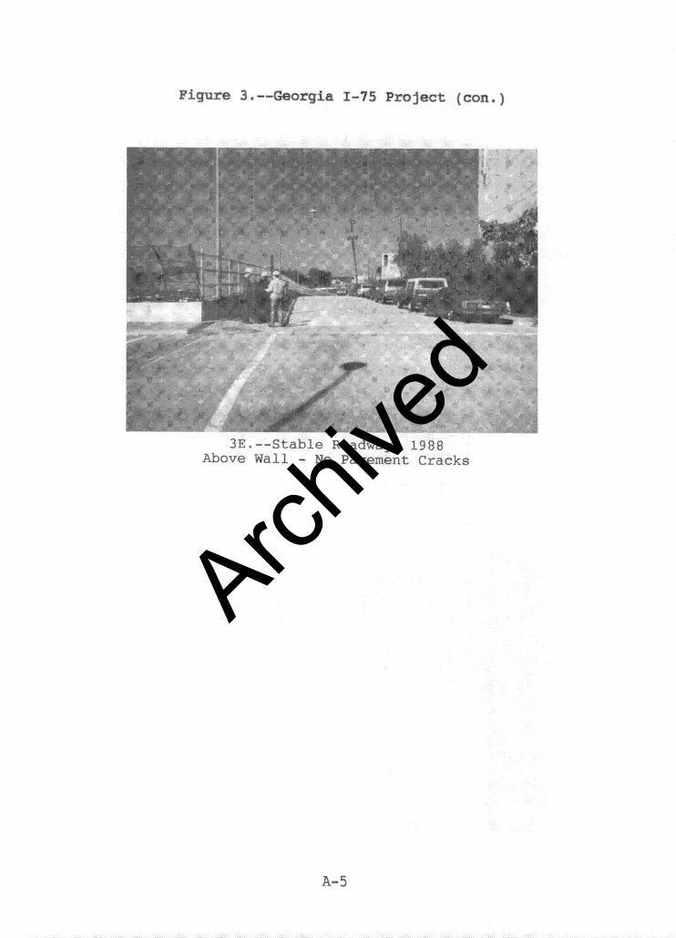
Figure 3 .--Georgia I-75 Project (con.)
3E.--Stable Roadway, 1988 Above Wall - No Pavement Cracks
Archive
d
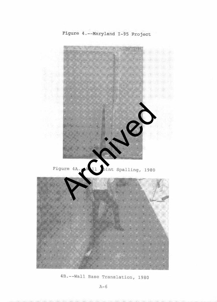
Figure 4 .--Maryland I-95 Project
Figure 4A.--Wall Joint Spalling, 1980
4B.--Wall Base Translation, 1980
A-6
Archive
d
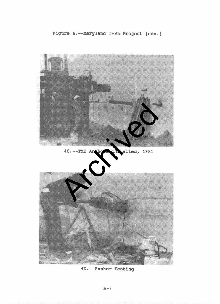
Figure 4 .--Maryland I-95 Project (con.)
4c .--TMD Anchors Installed, 1981
4D .--Anchor Testing
A-l
Archive
d
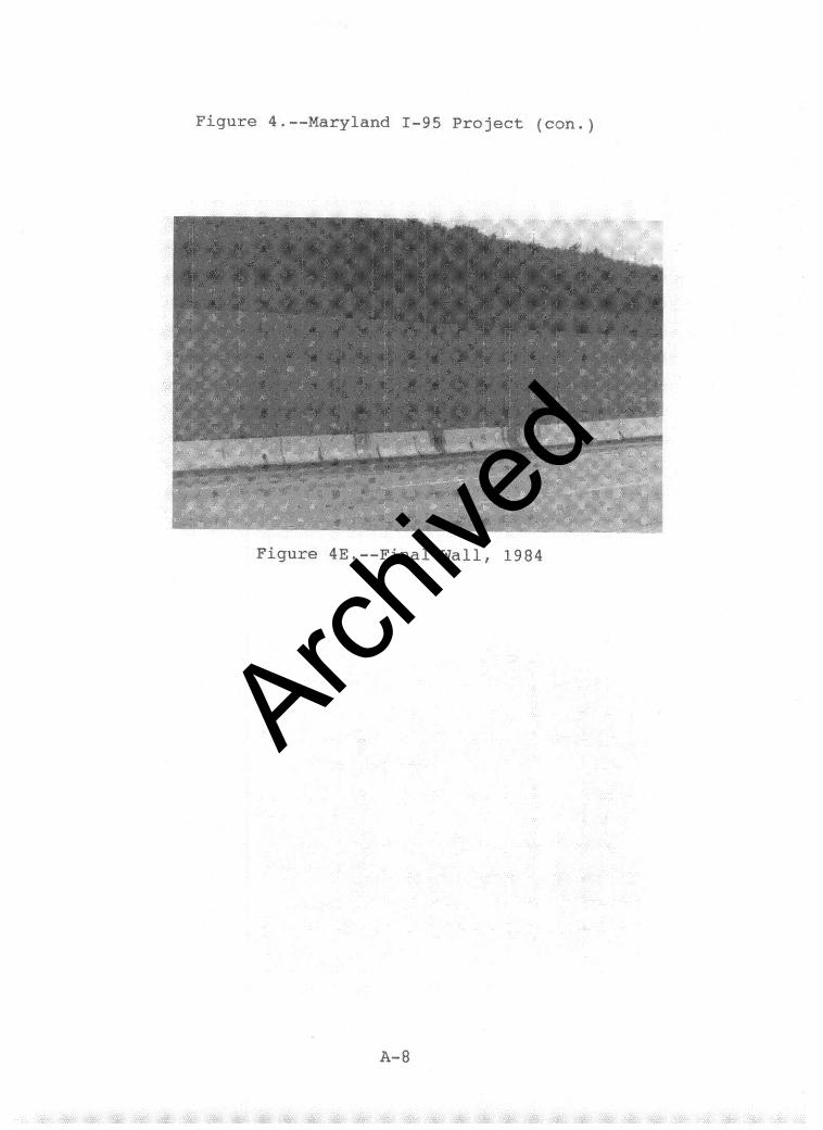
Figure 4.--Maryland I-95 Project (con.)
Figure 4E.--Final Wall, 1984
Archive
d
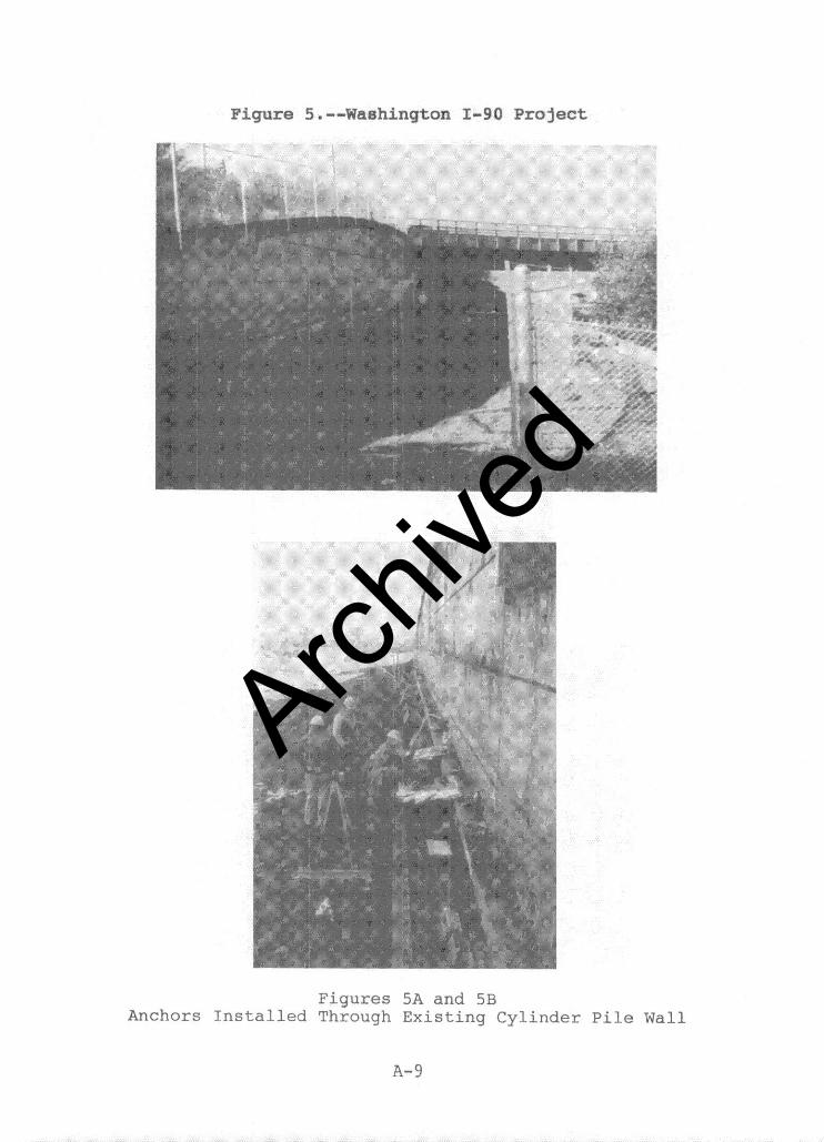
Figure 5 .--Washington I-90 Project
., S*’ (’
_ ..‘.
#
/
I
‘.
I
Figures 5A and SB Anchors Installed Through Existing Cylinder Pile Wall
A-9
Archive
d
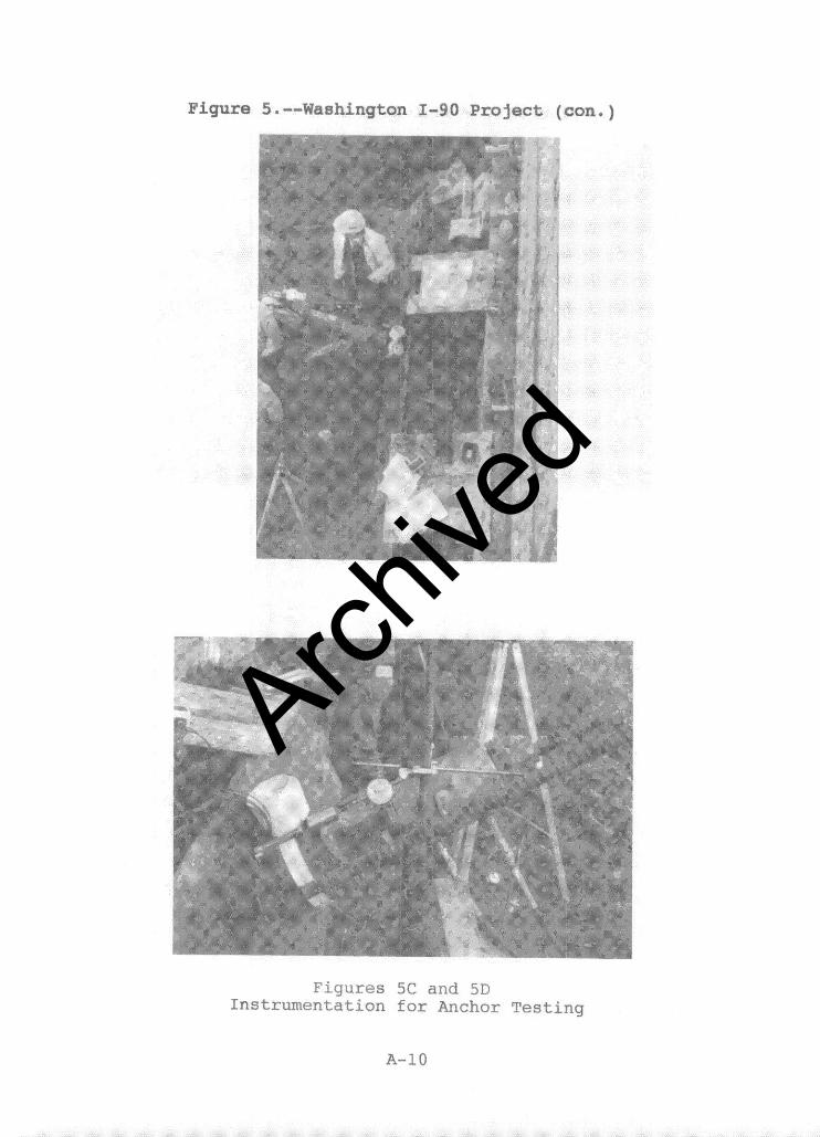
Figures 5C and 5D Instrumentation for Anchor Testing
A-10
Archive
d
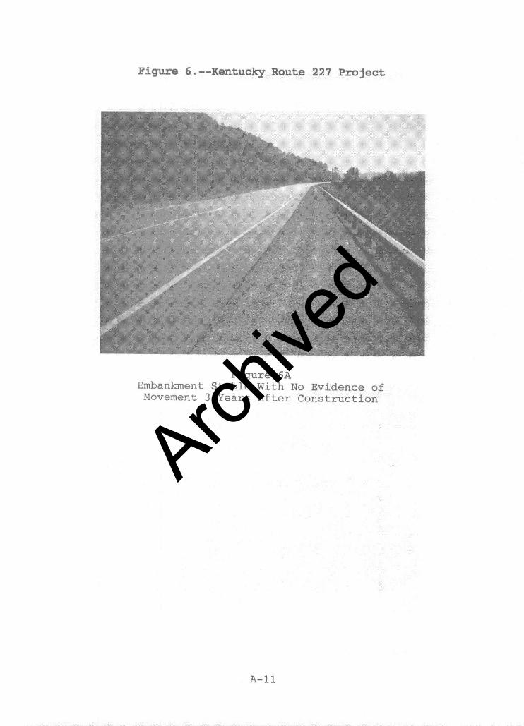
Figure 6 .--Kentucky Route 227 Project:
Figure 6A Embankment Stable With No Evidence of Movement 3 Years After Construction
A-11
Archive
d
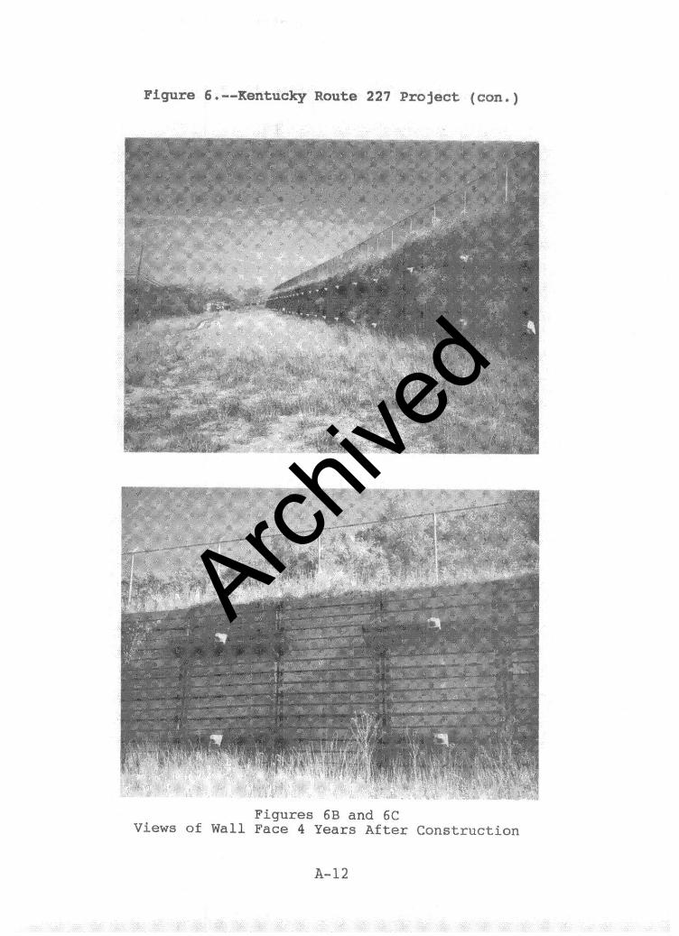
Figure 6 .--Kentucky Route 227 Project (can.)
Figure6 6B and 6C Views of Wall Face 4 Years After Construction
A-12
Archive
d
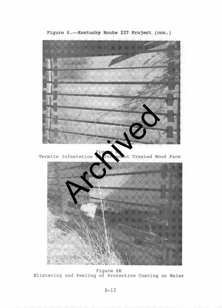
Figure 6 .--Kentucky Route 227 Project (con.)
Figure 6D Termite Infestation of Permanent Treated Wood Face
Figure 6E Blistering and Peeling of Protective Coating on Waler
B-13
Archive
d
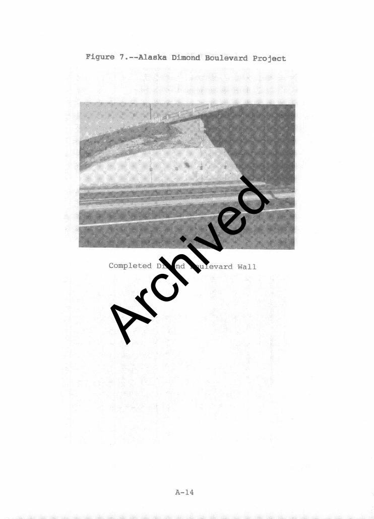
Figure 7 .--Alaska Dimond Boulevard Project
Completed Dimond Boulevard Wall
A-14
Archive
d
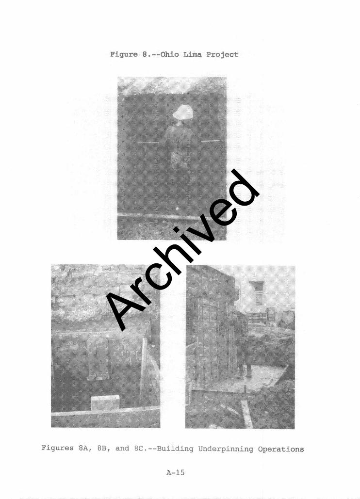
Figure 8 .--Ohio Lima Project
Figures 8A, 8B, and 8C.--Building Underpinning Operations
A-15
Archive
d
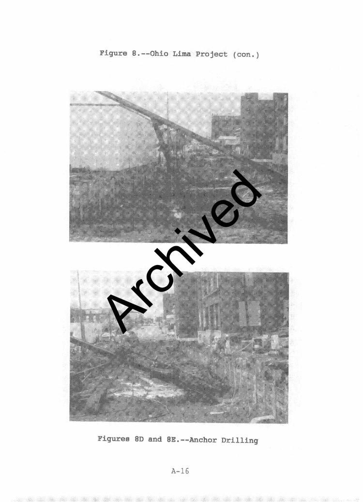
Figure 8 .--Ohio Lima Project (con.)
I / c - . . F II - :x ,
Figures 8D and 8E .--Anchor Drilling
A-16
Archive
d
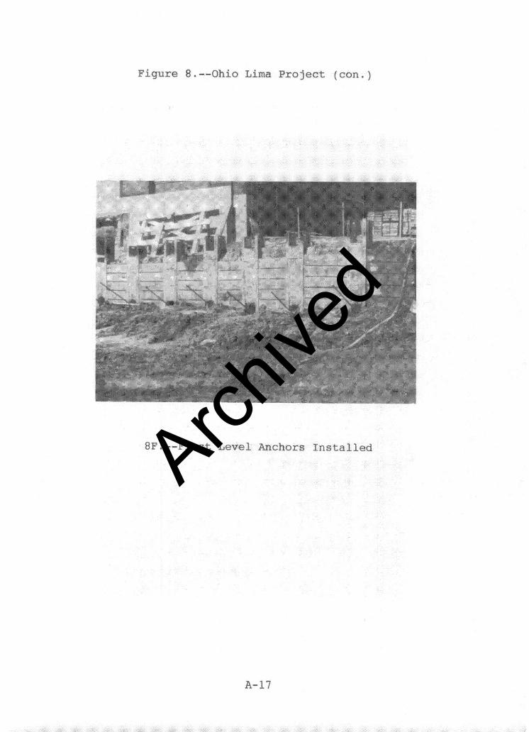
Figure 8 .--Ohio Lima Project (con.)
OF.--First Level Anchors Installed
A-17
Archive
d
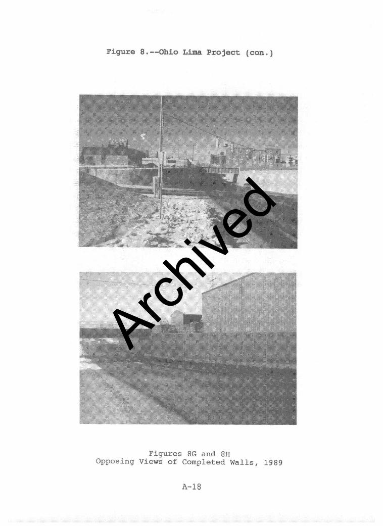
Figure 8 .--Ohio Lima Project (con.)
Figures 8G and 8H Opposing Views of Completed Walls, 1989
A-18
Archive
d
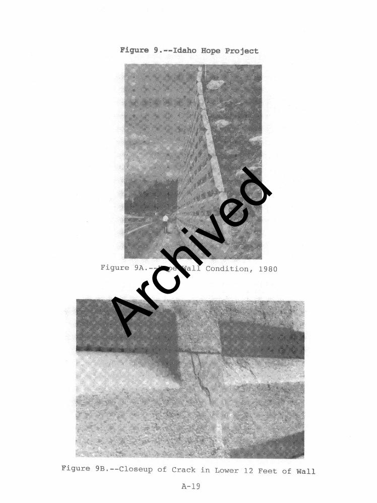
Figure 9A.--Hope Wall Condition, 1980
Figure 9B .--Closeup of Crack in Lower 12 Feet of Wall
A-19
Archive
d
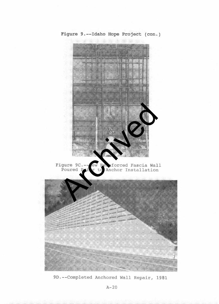
Figure 9 .--Idaho Hope Project (con.)
Figure 9C.--New Reinforced Fascia Wall Poured Prior to Anchor Installation
9D.--Completed Anchored Wall Repair, 1981
A-20
Archive
d
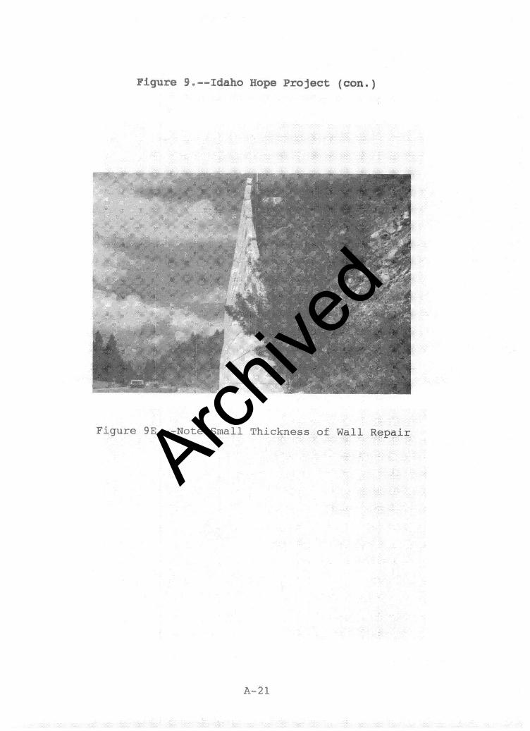
Figure 9 .--Idaho Rope Project (con.)
Figure 9E.-- Note Small Thickness of Wall Repair
Archive
d
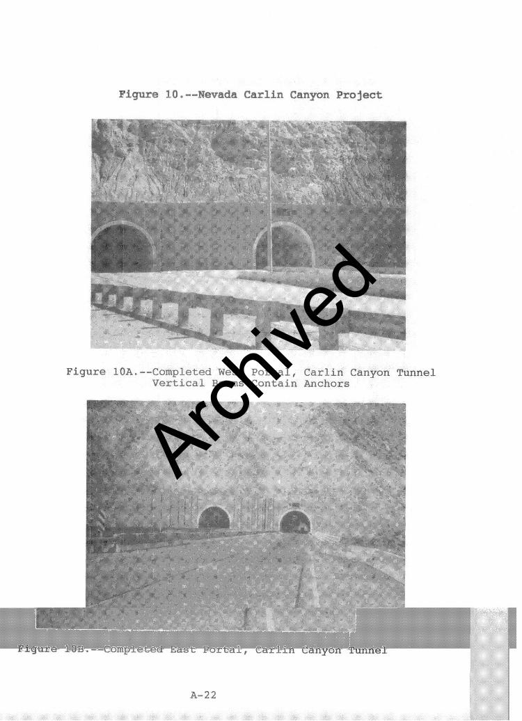
Figure 10 .--Nevada Carlin Canyon Project
Figure lOA.--Completed West Portal, Carlin Canyon Tunnel Vertical Beams Contain Anchors
Figure lOB.--Completed East Portal, C'arlin Canyon Tunnel
A-22
Archive
d