Embed Size (px)
Citation preview

IMAQ™
IMAQVision Builder Tutorial
IMAQ Vision Builder Tutorial
December 2000 EditionPart Number 322228C-01

Worldwide Technical Support and Product Information
ni.com
National Instruments Corporate Headquarters
11500 North Mopac Expressway Austin, Texas 78759-3504 USA Tel: 512 794 0100
Worldwide Offices
Australia 03 9879 5166, Austria 0662 45 79 90 0, Belgium 02 757 00 20, Brazil 011 284 5011,Canada (Calgary) 403 274 9391, Canada (Ottawa) 613 233 5949, Canada (Québec) 514 694 8521,China (Shanghai) 021 6555 7838, China (ShenZhen) 0755 3904939, Denmark 45 76 26 00,Finland 09 725 725 11, France 01 48 14 24 24, Germany 089 741 31 30, Greece 30 1 42 96 427,Hong Kong 2645 3186, India 91805275406, Israel 03 6120092, Italy 02 413091, Japan 03 5472 2970,Korea 02 596 7456, Mexico 5 280 7625, Netherlands 0348 433466, New Zealand 09 914 0488,Norway 32 27 73 00, Poland 0 22 528 94 06, Portugal 351 1 726 9011, Singapore 2265886, Spain 91 640 0085,Sweden 08 587 895 00, Switzerland 056 200 51 51, Taiwan 02 2528 7227, United Kingdom 01635 523545
For further support information, see the Technical Support Resources appendix. To comment on thedocumentation, send e-mail to [email protected]
© Copyright 1999, 2000 National Instruments Corporation. All rights reserved.

Important Information
WarrantyThe media on which you receive National Instruments software are warranted not to fail to execute programming instructions,due to defects in materials and workmanship, for a period of 90 days from date of shipment, as evidenced by receipts or otherdocumentation. National Instruments will, at its option, repair or replace software media that do not execute programminginstructions if National Instruments receives notice of such defects during the warranty period. National Instruments does notwarrant that the operation of the software shall be uninterrupted or error free.
A Return Material Authorization (RMA) number must be obtained from the factory and clearly marked on the outside ofthe package before any equipment will be accepted for warranty work. National Instruments will pay the shipping costs ofreturning to the owner parts which are covered by warranty.
National Instruments believes that the information in this document is accurate. The document has been carefully reviewedfor technical accuracy. In the event that technical or typographical errors exist, National Instruments reserves the right tomake changes to subsequent editions of this document without prior notice to holders of this edition. The reader should consultNational Instruments if errors are suspected. In no event shall National Instruments be liable for any damages arising out ofor related to this document or the information contained in it.
EXCEPT AS SPECIFIED HEREIN, NATIONAL INSTRUMENTS MAKES NO WARRANTIES, EXPRESS OR IMPLIED, AND SPECIFICALLY DISCLAIMS ANY
WARRANTY OF MERCHANTABILITY OR FITNESS FOR A PARTICULAR PURPOSE. CUSTOMER’S RIGHT TO RECOVER DAMAGES CAUSED BY FAULT OR
NEGLIGENCE ON THE PART OF NATIONAL INSTRUMENTS SHALL BE LIMITED TO THE AMOUNT THERETOFORE PAID BY THE CUSTOMER. NATIONAL
INSTRUMENTS WILL NOT BE LIABLE FOR DAMAGES RESULTING FROM LOSS OF DATA, PROFITS, USE OF PRODUCTS, OR INCIDENTAL OR
CONSEQUENTIAL DAMAGES, EVEN IF ADVISED OF THE POSSIBILITY THEREOF. This limitation of the liability of National Instruments willapply regardless of the form of action, whether in contract or tort, including negligence. Any action against National Instrumentsmust be brought within one year after the cause of action accrues. National Instruments shall not be liable for any delay inperformance due to causes beyond its reasonable control. The warranty provided herein does not cover damages, defects,malfunctions, or service failures caused by owner’s failure to follow the National Instruments installation, operation, ormaintenance instructions; owner’s modification of the product; owner’s abuse, misuse, or negligent acts; and power failure orsurges, fire, flood, accident, actions of third parties, or other events outside reasonable control.
CopyrightUnder the copyright laws, this publication may not be reproduced or transmitted in any form, electronic or mechanical, includingphotocopying, recording, storing in an information retrieval system, or translating, in whole or in part, without the prior writtenconsent of National Instruments Corporation.
TrademarksIMAQ™, LabVIEW™, National Instruments™, and ni.com™ are trademarks of National Instruments Corporation.
Product and company names mentioned herein are trademarks or trade names of their respective companies.
WARNING REGARDING USE OF NATIONAL INSTRUMENTS PRODUCTS(1) NATIONAL INSTRUMENTS PRODUCTS ARE NOT DESIGNED WITH COMPONENTS AND TESTING FOR A LEVELOF RELIABILITY SUITABLE FOR USE IN OR IN CONNECTION WITH SURGICAL IMPLANTS OR AS CRITICALCOMPONENTS IN ANY LIFE SUPPORT SYSTEMS WHOSE FAILURE TO PERFORM CAN REASONABLY BEEXPECTED TO CAUSE SIGNIFICANT INJURY TO A HUMAN.
(2) IN ANY APPLICATION, INCLUDING THE ABOVE, RELIABILITY OF OPERATION OF THE SOFTWARE PRODUCTSCAN BE IMPAIRED BY ADVERSE FACTORS, INCLUDING BUT NOT LIMITED TO FLUCTUATIONS IN ELECTRICALPOWER SUPPLY, COMPUTER HARDWARE MALFUNCTIONS, COMPUTER OPERATING SYSTEM SOFTWAREFITNESS, FITNESS OF COMPILERS AND DEVELOPMENT SOFTWARE USED TO DEVELOP AN APPLICATION,INSTALLATION ERRORS, SOFTWARE AND HARDWARE COMPATIBILITY PROBLEMS, MALFUNCTIONS ORFAILURES OF ELECTRONIC MONITORING OR CONTROL DEVICES, TRANSIENT FAILURES OF ELECTRONICSYSTEMS (HARDWARE AND/OR SOFTWARE), UNANTICIPATED USES OR MISUSES, OR ERRORS ON THE PART OFTHE USER OR APPLICATIONS DESIGNER (ADVERSE FACTORS SUCH AS THESE ARE HEREAFTERCOLLECTIVELY TERMED “SYSTEM FAILURES”). ANY APPLICATION WHERE A SYSTEM FAILURE WOULDCREATE A RISK OF HARM TO PROPERTY OR PERSONS (INCLUDING THE RISK OF BODILY INJURY AND DEATH)SHOULD NOT BE RELIANT SOLELY UPON ONE FORM OF ELECTRONIC SYSTEM DUE TO THE RISK OF SYSTEMFAILURE. TO AVOID DAMAGE, INJURY, OR DEATH, THE USER OR APPLICATION DESIGNER MUST TAKEREASONABLY PRUDENT STEPS TO PROTECT AGAINST SYSTEM FAILURES, INCLUDING BUT NOT LIMITED TOBACK-UP OR SHUT DOWN MECHANISMS. BECAUSE EACH END-USER SYSTEM IS CUSTOMIZED AND DIFFERSFROM NATIONAL INSTRUMENTS' TESTING PLATFORMS AND BECAUSE A USER OR APPLICATION DESIGNERMAY USE NATIONAL INSTRUMENTS PRODUCTS IN COMBINATION WITH OTHER PRODUCTS IN A MANNER NOTEVALUATED OR CONTEMPLATED BY NATIONAL INSTRUMENTS, THE USER OR APPLICATION DESIGNER ISULTIMATELY RESPONSIBLE FOR VERIFYING AND VALIDATING THE SUITABILITY OF NATIONALINSTRUMENTS PRODUCTS WHENEVER NATIONAL INSTRUMENTS PRODUCTS ARE INCORPORATED IN ASYSTEM OR APPLICATION, INCLUDING, WITHOUT LIMITATION, THE APPROPRIATE DESIGN, PROCESS ANDSAFETY LEVEL OF SUCH SYSTEM OR APPLICATION.

Conventions
The following conventions are used in this manual:
» The » symbol leads you through nested menu items and dialog box optionsto a final action. The sequence File»Page Setup»Options directs you topull down the File menu, select the Page Setup item, and select Optionsfrom the last dialog box.
This icon denotes a tip, which alerts you to advisory information.
This icon denotes a note, which alerts you to important information.
bold Bold text denotes items that you must select or click on in the software,such as menu items and dialog box options. Bold text also denotesparameter names.
italic Italic text denotes variables, emphasis, a cross reference, or an introductionto a key concept. This font also denotes text that is a placeholder for a wordor value that you must supply.
monospace Text in this font denotes text or characters that you should enter from thekeyboard, sections of code, programming examples, and syntax examples.This font is also used for the proper names of disk drives, paths, directories,programs, subprograms, subroutines, device names, functions, operations,variables, filenames and extensions, and code excerpts.

© National Instruments Corporation v IMAQ Vision Builder Tutorial
Contents
Chapter 1System Requirements and Installation
System Requirements ....................................................................................................1-1Installing IMAQ Vision Builder ....................................................................................1-2Launching and Exiting IMAQ Vision Builder ..............................................................1-2IMAQ Vision Builder Environment ..............................................................................1-3
Features............................................................................................................1-3Image Analysis Functions ...............................................................................1-4Color Image Processing Functions..................................................................1-5Grayscale Image Processing and Analysis Functions .....................................1-5Binary Processing and Analysis Functions .....................................................1-6Machine Vision Functions...............................................................................1-6Calibration Functions ......................................................................................1-7
Getting Help...................................................................................................................1-7IMAQ Vision Builder Online Help .................................................................1-7IMAQ Vision Documentation .........................................................................1-8National Instruments Web Site........................................................................1-8IMAQ Vision Builder Scripts..........................................................................1-9
Chapter 2Introduction to Image Processing with IMAQ Vision Builder
Getting Started in IMAQ Vision Builder.......................................................................2-1Acquiring Images in IMAQ Vision Builder ..................................................................2-7
Opening the Acquisition Window...................................................................2-8Snapping an Image (Single Acquisition).........................................................2-10Grabbing an Image (Continuous Acquisition) ................................................2-10Acquiring a Sequence of Images.....................................................................2-11
Chapter 3Using Blob Analysis to Analyze the Structure of a Metal
What Is Blob Analysis? .................................................................................................3-1Tutorial...........................................................................................................................3-1
Loading Images into IMAQ Vision Builder....................................................3-2Preparing an Image for Blob Analysis ............................................................3-2
Examining the Image ........................................................................3-3Filtering the Image ............................................................................3-5Examining the Results of the Filtering .............................................3-5
Separating Particles from the Background with Thresholding........................3-6

Contents
IMAQ Vision Builder Tutorial vi ni.com
Modifying Blobs with Morphological Functions............................................ 3-8Isolating Circular Blobs .................................................................................. 3-9Analyzing Circular Blobs................................................................................ 3-10Testing the Blob Analysis Script .................................................................... 3-10Saving the Blob Analysis Script ..................................................................... 3-13Estimating Processing Time............................................................................ 3-13Creating a LabVIEW VI ................................................................................. 3-14
Chapter 4Using Gauging for Part Inspection
What Is Gauging? .......................................................................................................... 4-1Tutorial .......................................................................................................................... 4-1
Loading Images into IMAQ Vision Builder ................................................... 4-3Finding Measurement Points Using Pattern Matching ................................... 4-3Finding Edges in the Image ............................................................................ 4-6Taking the Measurements ............................................................................... 4-7Analyzing a Collection of Images with Batch Processing.............................. 4-10Analyzing the Results ..................................................................................... 4-11
Appendix ATechnical Support Resources
Glossary
Index

© National Instruments Corporation 1-1 IMAQ Vision Builder Tutorial
1System Requirementsand Installation
This chapter lists system requirements and installation instructions andintroduces the IMAQ Vision Builder environment.
System RequirementsTo run IMAQ Vision Builder, you must have the following minimumsystem requirements:
• Personal computer using at least a 133 MHz Pentium or highermicroprocessor (233 MHz Pentium MMX or higher microprocessorrecommended)
• Microsoft Windows 2000/NT/Me/9x. If you are usingWindows NT 4.0, you must have Service Pack 3 or higher installed onyour computer to run IMAQ Vision Builder.
• 800 × 600 resolution (or higher) video adapter, 65,536 colors (16-bit)or higher
• National Instruments image acquisition (IMAQ) hardware andNI-IMAQ 2.5 or higher for Windows 2000/NT/Me/9x (if you areacquiring images)
• Minimum of 32 MB RAM (64 MB recommended)
• Minimum of 40 MB of free hard disk space
Note You need Microsoft Excel 97 or higher installed on your computer to complete a fewsteps in the second tutorial.

Chapter 1 System Requirements and Installation
IMAQ Vision Builder Tutorial 1-2 ni.com
Installing IMAQ Vision Builder
Note To install IMAQ Vision Builder on a Windows NT or Windows 2000 system, youmust be logged in with Administrator privileges.
1. Insert the IMAQ Vision Builder CD into your CD-ROM drive.
If the CD startup screen does not appear, use Windows Explorer to runthe SETUP.EXE program in the \Setup directory on the CD.
2. Follow the setup instructions you see on your screen.
By default, the IMAQ Vision Builder installation program creates a newfolder, \Program Files\National Instruments\IMAQ Vision Builder 6, that contains the following items:
• program folder—IMAQ Vision Builder.exe, the online help file,function libraries, and other related program files
• readme.txt—Late-breaking information about IMAQ VisionBuilder
• examples folder—Images and scripts that you need to complete theexample tutorials in this manual
• manuals folder—Portable Document Format (PDF) versions of theIMAQ Vision Concepts Manual, IMAQ Vision Builder Release Notes,and this manual. You must have Adobe Acrobat Reader installed toaccess these documents.
• solutions folder—Example images and scripts
Launching and Exiting IMAQ Vision BuilderTo launch IMAQ Vision Builder in Windows, point toStart»Programs»National Instruments IMAQ Vision Builder 6.
To quit IMAQ Vision Builder, follow these steps:
1. Close any open parameter windows.
2. Save your script and images if you want to keep them.
3. Select File»Exit.

Chapter 1 System Requirements and Installation
© National Instruments Corporation 1-3 IMAQ Vision Builder Tutorial
IMAQ Vision Builder EnvironmentIMAQ Vision Builder is a tool for prototyping and testing imageprocessing applications. To prototype your image processing application,you build custom algorithms with the IMAQ Vision Builder scriptingfeature. The scripting feature records every step of your processingalgorithm. After completing the algorithm, you can test it on other imagesto make sure it works.
The algorithm is recorded in a Builder file. Builder files are ASCII text filesthat list the processing functions and relevant parameters for an algorithmthat you prototype in IMAQ Vision Builder. Using the LabVIEW VIcreation wizard, you can create a LabVIEW VI that performs the prototypethat you created in IMAQ Vision Builder.
Note You must have LabVIEW 6.0 or higher and IMAQ Vision 6 for LabVIEW or higherinstalled on your machine to use this feature.
For more information on LabVIEW VI creation, see Creating a LabVIEWVI in Chapter 3, Using Blob Analysis to Analyze the Structure of a Metal.
You can also implement the algorithm defined by the Builder file into anydevelopment environment, such as LabWindows/CVI or Visual Basic,using the IMAQ Vision machine vision and image processing libraries.
FeaturesIMAQ Vision Builder offers the following features:
• Script window—Records a series of image processing steps and thesettings you use for each of those steps. You can run scripts on singleimages or image collections (batch processing). You can modify andsave scripts. See Figure 2-4, Thresholded Image, to view a script in theScript window.
• Image Browser—Contains all of the images currently loaded inIMAQ Vision Builder. Through the Image Browser, you can select animage to process by double-clicking on it. See Figure 2-1, ImageBrowser, to view images loaded into the Image Browser.
• Acquisition window—Displays the Interfaces window (IMAQ imageacquisition boards and channels available) and the property pages forthe IMAQ image acquisition board. See Figure 2-5, Acquiring Imagesin IMAQ Vision Builder, to view all the elements of the Acquisitionwindow.

Chapter 1 System Requirements and Installation
IMAQ Vision Builder Tutorial 1-4 ni.com
• Processing window—Updates the image as you change parameters.Because this view immediately reflects the changes you have made inthe parameters window, you can continue modifying parameters untilyou get the desired result. See Figure 2-2, Processing an Image, toview an image loaded into the Processing window.
• Parameter window—Displays parameters that you can set for an imageprocessing function. Each IMAQ Vision function available through themenus has a parameter window in which you set the parameters forthat function. See Figure 2-3, Thresholding an Image, to view anexample of the threshold Parameter window.
• Reference window—Displays the original version of the image(image source) as you manipulate it in the processing window. SeeFigure 2-2, Processing an Image, to view an image in the Referencewindow.
• Tools palette—Displays a collection of tools for selecting regions ofinterest (ROIs), zooming in and out, and changing the Image palette.See Figure 2-4, Thresholded Image, to view the Tools palette.
• Solution Wizard—Displays a list of industries and correspondingquality-assurance tasks that those industries perform. Based on thetask the user selects, the wizard loads an IMAQ Vision-based solutionto the task.
• Performance Meter—Estimates how long your script will take tocomplete in IMAQ Vision on a given image.
• LabVIEW VI Creation—Creates the LabVIEW and IMAQ Vision VIcorresponding to the algorithm you prototype in IMAQ Vision Builder.Based on the options you select, the LabVIEW VI creation wizardcreates a new VI that implements the image processing steps of thecurrent script or of a saved script file.
Image Analysis FunctionsIMAQ Vision Builder offers several image analysis functions, includingthe following:
• Histogram—Counts the total number of pixels in each grayscale valueand graphs the result
• Line Profile—Returns the grayscale values of the pixels along a linethat you draw with the Line Tool from the Tools palette and graphs theresult
• 3D View—Displays an image using an isometric view. Each pixelfrom the image source is represented as a column of pixels in the3D view. The pixel value corresponds to the altitude.

Chapter 1 System Requirements and Installation
© National Instruments Corporation 1-5 IMAQ Vision Builder Tutorial
Color Image Processing FunctionsIMAQ Vision Builder includes a comprehensive set of functions forprocessing and analyzing color images, including the following:
• Color Operators—Applies an arithmetic operation betweentwo images or between an image and a constant
• Color Plane Extraction—Extracts the Red, Green, or Blue plane or theHue, Saturation, or Luminance plane of a color image
• Color Threshold—Applies a threshold to the three planes of an RGBor HSL image
• Color Location—Locates colors in an image
• Color Matching—Compares the color content of one or multipleregions in an image to a reference color set
• Color Pattern Matching—Searches for a color template in an image
Grayscale Image Processing and Analysis FunctionsIMAQ Vision Builder also includes functions for grayscale imageprocessing and analysis:
• Filtering—Functions for smoothing, edge detection, and convolution
• Lookup Tables—Applies predefined lookup table transformations tothe image to modify the dynamic intensity of regions in the image withpoor contrast
• Operators—Performs basic arithmetic and logical operations onimages
• Grayscale Morphology—Modifies the shape of objects in grayscaleimages using erosion, dilation, opening, and closing functions
• Threshold—Isolates pixels that interest you and sets the remainingpixels as background pixels
• Quantify—Measures the intensity statistics of one or multiple regionsin an image
• Centroid—Computes the energy center of a grayscale image or area ofinterest

Chapter 1 System Requirements and Installation
IMAQ Vision Builder Tutorial 1-6 ni.com
Binary Processing and Analysis FunctionsIMAQ Vision Builder contains functions for binary processing andanalysis:
• Binary Morphology—Performs morphology transformations thatmodify the shape of objects in binary images
• Invert Binary Image—Reverses the dynamic of an image that containstwo different grayscale populations
• Particle Filtering—Filters objects based on shape measurements
• Particle Analysis—Computes more than 40 measurements on objectsin an image, including the area and perimeter of the objects
• Circle Detection—Separates overlapping circular objects andclassifies them according to their radii
Machine Vision FunctionsIMAQ Vision Builder features several machine vision functions, such asthe following:
• Edge Detection—Finds edges along a line that you draw with theLine Tool from the Tools palette
• Find Straight Edge—Finds points within the edge of an object and thenfinds a line describing the edge
• Find Circular Edge—Locates the intersection points between a set ofsearch lines within a circular area (annulus), and then finds the best fitcircle
• Clamp—Finds edges within a rectangular ROI drawn in the image andmeasures the distance between the first and last edge
• Pattern Matching—Locates regions of a grayscale image that match apredetermined template. Pattern Matching can find template matchesregardless of poor lighting, blur, noise, shifting of the template, androtation of the template
• Caliper—Computes measurements—such as distances, areas, andangles—based on results returned from other machine vision andimage processing functions
Chapter 1 System Requirements and Installation
© National Instruments Corporation 1-7 IMAQ Vision Builder Tutorial
Calibration FunctionsIMAQ Vision Builder features several calibration functions, including thefollowing:
• Simple Calibration—Sets a simple calibration for an image. Thisfunction sets the horizontal and vertical scaling factor, as well as theorigin and orientation of the coordinate system for the image.
• Grid Calibration—Learns a calibration based on the image of a gridtemplate acquired with the imaging setup you are calibrating
• Calibration from Image—Applies the calibration information saved inan image file to the current image
• Image Correction—Transforms a distorted image acquired in acalibrated setup into an image where perspective errors and lensdistortion are corrected
Getting HelpAs you work with IMAQ Vision Builder, you may need to consult othersources if you have questions. The following sources can provide you withmore specific information about IMAQ Vision, IMAQ hardware, andimaging.
IMAQ Vision Builder Online HelpIMAQ Vision Builder offers tooltips and online help that you can access inthe following ways:
• Access the IMAQ Vision Builder online help by selecting Online Helpfrom the Help menu. There you can find information not available inthis manual, such as function descriptions and directions forperforming image processing functions.
• Move the cursor over a button to see tooltips on buttons in theProcessing toolbar, Tools palette, Script window, Reference window,Acquisition window, or Image Browser.
• Click the Help button in any function parameter window to getinformation about that function and its parameters.

Chapter 1 System Requirements and Installation
IMAQ Vision Builder Tutorial 1-8 ni.com
IMAQ Vision DocumentationIf you have purchased IMAQ Vision software from National Instruments,you also have one of the following sets of documentation, depending on thedevelopment environment you use.
• IMAQ Vision for LabVIEW
– IMAQ Vision for LabVIEW User Manual—Contains informationabout how to build a Vision application using IMAQ Vision forLabVIEW.
– IMAQ Vision for LabVIEW online help (from inside theLabVIEW environment: Help»IMAQ Vision)—Containsreference information about IMAQ Vision VIs.
• IMAQ Vision for Measurement Studio
– IMAQ Vision for Measurement Studio User Manual:LabWindows/CVI—Contains information about how to build avision application using IMAQ Vision for LabWindows/CVI.
– IMAQ Vision for LabWindows/CVI online help—Containsreference information about IMAQ Vision for LabWindows/CVI.
– IMAQ Vision for Measurement Studio User Manual:Visual Basic—Contains information about how to build a Visionapplication using the tools for Visual Basic that come withIMAQ Vision for Measurement Studio.
– IMAQ Vision for Visual Basic online help—Contains referenceinformation about the tools for Visual Basic that come with IMAQVision for Measurement Studio.
For detailed information about the concepts and algorithms used byIMAQ Vision Builder, launch the IMAQ Vision Concepts Manual from theStart menu (Start»Programs»National Instruments»IMAQ VisionBuilder 6»IMAQ Vision Concepts Manual).
National Instruments Web SiteThe National Instruments Web site provides information about IMAQhardware and software. Visit the site at ni.com/imaq.
From the IMAQ site, you can locate information about new IMAQ Visionfeatures, machine vision problems and solutions, using MMX technologyon machine vision applications, and selecting the appropriate IMAQhardware, cameras, lenses, and lighting equipment for your application.

Chapter 1 System Requirements and Installation
© National Instruments Corporation 1-9 IMAQ Vision Builder Tutorial
The NI Developer Zone at ni.com/zone is the essential resource forbuilding measurement and automation systems. At the NI Developer Zone,you can easily access the latest example programs, system configurators,tutorials, technical news, as well as a community of developers ready toshare their own techniques.
IMAQ Vision Builder ScriptsYou installed several example scripts when you installed IMAQ VisionBuilder. You can run these scripts to learn more about IMAQ VisionBuilder scripting capabilities. You also can customize these scripts foryour own applications. By default, the scripts are installed at \Program Files\National Instruments\IMAQ Vision Builder
6\Examples and at \Program Files\National Instruments\IMAQ Vision Builder 6\Solutions.

© National Instruments Corporation 2-1 IMAQ Vision Builder Tutorial
2Introduction to ImageProcessing withIMAQ Vision Builder
This chapter describes how you can use IMAQ Vision Builder to create andtest your own image processing algorithms. It explains how to get startedin IMAQ Vision Builder. For detailed information about digital images, seeChapter 1, Digital Images, in the IMAQ Vision Concepts Manual.
Getting Started in IMAQ Vision BuilderThis section describes the software-specific terminology that you needto complete the tutorials in this manual and understand the online help.The best way to understand how IMAQ Vision Builder works and whatyou can accomplish with IMAQ Vision Builder is by using it.
In this short example, you load images into IMAQ Vision Builder andperform one image processing function—a threshold. Thresholdingisolates objects so that you can keep those that interest you and removethose that do not. Thresholding also converts the image from a grayscaleimage, with pixel values ranging from 0 to 255, to a binary image, withpixel values of 0 or 1.
Follow these steps to get started in IMAQ Vision Builder:
1. Launch IMAQ Vision Builder from the Start menu(Start»Programs»National Instruments IMAQ Vision Builder 6).
2. To load images, select the Open Image button from the WelcomeScreen.
3. Navigate to Program Files\National Instruments\IMAQ
Vision Builder 6\Examples\Metal and check the Select AllFiles option. IMAQ Vision Builder previews the images in the PreviewImage window and displays information about the file type and imagedepth.
4. Click OK.

Chapter 2 Introduction to Image Processing with IMAQ Vision Builder
IMAQ Vision Builder Tutorial 2-2 ni.com
IMAQ Vision Builder loads those image files into the Image Browser,as shown in Figure 2-1. The Image Browser provides informationabout the selected image, such as image size, location, and type.
Figure 2-1. Image Browser
You can view new images in either thumbnail view, as shown inFigure 2-1, or in full-size view, which shows a single full-size view ofthe selected image.
5. Click the Thumbnail/Full-Size View Toggle button to view the firstimage in full size.
1 Image Browser2 Image Location3 Browse Buttons
4 Thumbnail/Full-SizeToggle
5 Image Size
6 Close SelectedImage(s)
7 Image Type
8 File Format
4
1
2
3
6 7 85

Chapter 2 Introduction to Image Processing with IMAQ Vision Builder
© National Instruments Corporation 2-3 IMAQ Vision Builder Tutorial
6. To enter processing mode, double-click the image Metal1.jpg.IMAQ Vision Builder loads the image into the processing window,as shown in Figure 2-2.
Figure 2-2. Processing an Image
Tip The Reference window displays the original version of the image as you manipulateit in the Processing window.
1 Reference Window2 Script Window
3 Image Size4 Zoom Ratio
5 Processing Window
1 5
2 3 4
Chapter 2 Introduction to Image Processing with IMAQ Vision Builder
IMAQ Vision Builder Tutorial 2-4 ni.com
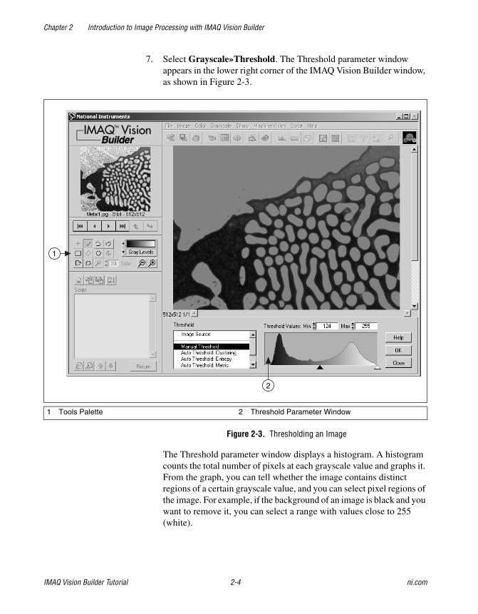
7. Select Grayscale»Threshold. The Threshold parameter windowappears in the lower right corner of the IMAQ Vision Builder window,as shown in Figure 2-3.
Figure 2-3. Thresholding an Image
The Threshold parameter window displays a histogram. A histogramcounts the total number of pixels at each grayscale value and graphs it.From the graph, you can tell whether the image contains distinctregions of a certain grayscale value, and you can select pixel regions ofthe image. For example, if the background of an image is black and youwant to remove it, you can select a range with values close to 255(white).
1 Tools Palette 2 Threshold Parameter Window
2
1

Chapter 2 Introduction to Image Processing with IMAQ Vision Builder
© National Instruments Corporation 2-5 IMAQ Vision Builder Tutorial
The Processing window displays a preview of the threshold operationusing the current set of parameters. The pixels depicted in red haveintensities that fall inside the threshold range. The threshold operatorsets their values to 1. The pixels depicted in gray have values outsidethe threshold range. The threshold operator sets their values to 0.
8. From the Threshold parameter window, specify settings that work bestfor your application. To threshold this image, set the Min value to 130and Max value to 255 to select all of the objects.
Tip You may need to manipulate the parameters several times to find the values that workbest. Rather than entering numbers in the Min and Max fields, you can select the rangeusing the pointers on the histogram. Adjust the pointers until all of the objects you want toselect are red. The black pointer marks the minimum value, and the white pointer marksthe maximum value.
9. Click OK to apply the manual threshold to the image. The image isconverted to a binary image where all of the selected pixels in thethreshold range are set to 1 (red) and all other pixels are setto 0 (black).

Chapter 2 Introduction to Image Processing with IMAQ Vision Builder
IMAQ Vision Builder Tutorial 2-6 ni.com
Refer to Figure 2-4 to see what the image looks like after applying thethreshold.
Figure 2-4. Thresholded Image
The thresholding step is recorded in the Script window. The scriptrecords the processing operation and all of its parameters. If you needto run the same operation on other images, you can save the script anduse it again.
1 Script Tools 2 Script Window
1 2

Chapter 2 Introduction to Image Processing with IMAQ Vision Builder
© National Instruments Corporation 2-7 IMAQ Vision Builder Tutorial
10. Select Script»Save Script and name the script threshold.scr.
If you find another image that you need to threshold similarly, run thisscript on the image using the following steps:
a. Load the image.
b. Select Script»Open Script to open threshold.scr.
c. Click the Run Script button in the script window.
Try experimenting with different options and images. For example,you can perform a particle analysis to find the area that each object inthis image occupies. If you need help with any specific imageprocessing operation, click the Help button in the parameter window.
11. Select File»Exit to close IMAQ Vision Builder.
Acquiring Images in IMAQ Vision BuilderIMAQ Vision Builder offers three types of image acquisitions: snap, grab,and sequence. A snap acquires and displays a single image. A grabacquires and displays a continuous sequence, which is useful, for example,when you need to focus your camera. A sequence acquires imagesaccording to settings that you specify and sends the images to the ImageBrowser.
If you have National Instruments IMAQ image acquisition boards andNI-IMAQ 2.5 or later installed on your computer, you can acquire liveimages in IMAQ Vision Builder. For more information on setting up yourboards and channels in Measurement & Automation Explorer (MAX),see the MAX online help.
If you do not have IMAQ image acquisition boards and NI-IMAQ 2.5 orlater installed on your computer, IMAQ Vision Builder automaticallysimulates the acquisition process by displaying a sequence of images. Youcan stop the sequence at any frame, capture the image, and send the imageto the Image Browser for processing.

Chapter 2 Introduction to Image Processing with IMAQ Vision Builder
IMAQ Vision Builder Tutorial 2-8 ni.com
Opening the Acquisition WindowIf IMAQ Vision Builder is not loaded, launch the application from theStart menu (Start»Programs»National InstrumentsIMAQ Vision Builder 6). Click the Acquire Image button from theWelcome Screen to view the Acquisition window, as shown in Figure 2-5.
If you already have IMAQ Vision Builder running, click theAcquire Image button in the toolbar. IMAQ Vision Builder displays theAcquisition window, as shown in Figure 2-5.
The acquisition plug-in list shows the different modules that you can use toacquire images:
• Simulation module
• Image acquisition board
The Interfaces window displays all IMAQ image acquisition boards andchannels available for your computer. Figure 2-5 shows that two IMAQhardware boards are available—the IMAQ PCI-1408 and theIMAQ PCI-1424.
Note The hardware boards listed in your Interfaces window will vary according to theboards plugged into your computer.

Chapter 2 Introduction to Image Processing with IMAQ Vision Builder
© National Instruments Corporation 2-9 IMAQ Vision Builder Tutorial
Figure 2-5. Acquiring Images in IMAQ Vision Builder
The property pages above the Interfaces window list properties availablefor the selected board. In Figure 2-5, the IMAQ PCI-1408 is selected.Because the PCI-1408 can acquire a sequence of images, you can set thefollowing properties for a Sequence acquisition. For information about theproperties of other IMAQ boards, see your hardware manual and the MAXonline help.
• Number of Frames—Number of frames you want to acquire
• Skip Count—Number of frames you want to skip betweenacquisitions
• Line—Physical trigger line
1 Acquisition Window2 Acquisition Property Page
3 Store Acquired Image in Browser Button4 IMAQ Image Acquisition Boards and Channels
1
2
3
4

Chapter 2 Introduction to Image Processing with IMAQ Vision Builder
IMAQ Vision Builder Tutorial 2-10 ni.com
• Action—Triggering action
– Disabled—Disables triggering
– Trigger start of acquisition
– Trigger each image
• Timeout—Time, in milliseconds, within which the trigger must occur
Note A trigger is any signal that causes or starts some form of data capture.
To set any other property of your image acquisition board or your camera,select the board or channel in the list, then click the MAX button to displaythe corresponding MAX property window.
See the MAX online help for more information on the MAX propertywindows.
Note Your computer must have a National Instruments IMAQ image acquisition boardand NI-IMAQ 2.5 or higher installed before you can acquire live images inIMAQ Vision Builder.
Snapping an Image (Single Acquisition)1. Make sure the Acquisition window is open.
2. Click the Acquire Single Image button to acquire a single image withthe IMAQ board and display it. This operation is also known as a snap.
Note If your computer does not have an IMAQ board, IMAQ Vision Builder simulates thelive acquisition process. You can interact with the simulation module as you would with alive acquisition.
3. Click the Store Acquired Image in Browser button to send the imageto the Image Browser.
4. Click Return to return to the Image Browser.
5. Process the image as you would any other image in IMAQVision Builder. See Chapter 3, Using Blob Analysis to Analyze theStructure of a Metal, and Chapter 4, Using Gaugingfor Part Inspection for examples of processing images in IMAQVision Builder.
Grabbing an Image (Continuous Acquisition)1. Make sure the Acquisition window is open.

Chapter 2 Introduction to Image Processing with IMAQ Vision Builder
© National Instruments Corporation 2-11 IMAQ Vision Builder Tutorial
2. Click the Acquire Continuous Images button to acquire and displayimages in continuous mode at the maximum rate. This operation is alsoknown as a grab.
3. Click the Acquire Continuous Images button again to stop theacquisition and display the last acquired image.
Tip You can acquire a region of interest within the full-sized image. Draw a region ofinterest in your image while grabbing it, and the image reduces to that area. You can refinethe acquired area again by selecting another region of interest or return to the full-sizedimage by clicking on the image.
4. Click the Store Acquired Image in Browser button to send the imageto the Image Browser.
5. Click Return to return to the Image Browser.
6. Process the image as you would any other image in IMAQ VisionBuilder. See Chapter 3, Using Blob Analysis to Analyze the Structureof a Metal, and Chapter 4, Using Gauging for Part Inspection, forexamples of processing images in IMAQ Vision Builder.
Acquiring a Sequence of Images1. Make sure the Acquisition window is open.
2. Set the properties for the Sequence property page.
3. Click the Sequence Acquisition button to acquire a sequence of liveimages. A panel describing the status of the Sequence acquisitionappears.
If you set the triggering action property to Disabled, click theStart Acquisition button to begin acquiring a sequence of images.
Images acquired are automatically sent to the Image Browser.
Note If your computer does not have an IMAQ board, IMAQ Vision Builder simulates thelive acquisition process. You can interact with the simulation module as you would with alive acquisition.
4. Click Return to return to the Image Browser.
5. Process the image as you would any other image in IMAQ VisionBuilder. See Chapter 3, Using Blob Analysis to Analyze the Structureof a Metal, and Chapter 4, Using Gauging for Part Inspection, forexamples of processing images in IMAQ Vision Builder.

© National Instruments Corporation 3-1 IMAQ Vision Builder Tutorial
3Using Blob Analysis to Analyzethe Structure of a Metal
This chapter describes blob analysis and provides step-by-step directionsfor prototyping a blob analysis application in IMAQ Vision Builder.
What Is Blob Analysis?Blob analysis consists of a series of processing operations and analysisfunctions to produce some information about the blobs in an image. A blob(binary large object) is defined as a connected region or grouping of pixelsin an image in which all pixels have the same intensity level. In a binaryimage, the background pixels are zero, and every non-zero pixel is part ofa binary object.
You perform a blob analysis to find statistical information—such as the sizeof the blobs or the number, location, and presence of blob regions. With thisinformation, you can detect flaws on silicon wafers, detect solderingdefects on electronic boards, or locate objects in motion controlapplications when there is significant variance in part shape or orientation.
TutorialIn this tutorial, you find the area of circular particles in a metal. As youperform this analysis, IMAQ Vision Builder records all of the processingoperations and parameters in a script. You will run that script on otherimages to test your blob analysis algorithm.
To find the total area of circular particles, you will perform the followingimage processing steps:
• Filter the image to sharpen edges and ease the separation of theparticles from the background.
• Threshold the image to isolate pixels that interest you (the particles).
• Fill holes that appear in the particles after thresholding.

Chapter 3 Using Blob Analysis to Analyze the Structure of a Metal
IMAQ Vision Builder Tutorial 3-2 ni.com
• Remove all objects touching the border so that you remove partialparticles.
• Use a particle filter to find all circular blobs and remove non-circularblobs.
• Perform a particle analysis to find the total area occupied by circularblobs.
Loading Images into IMAQ Vision Builder1. If IMAQ Vision Builder is not loaded, launch the application from
the Start menu (Start»Programs»National InstrumentsIMAQ Vision Builder 6). Click the Open Image button from theWelcome Screen.
If you already have IMAQ Vision Builder running, press theOpen Image button in the toolbar.
2. Navigate to Program Files\National Instruments\IMAQ
Vision Builder 6\Examples\Metal and check the Select AllFiles option. IMAQ Vision Builder previews the images in thePreview Image window and displays information about the fileformat, size, and pixel depth.
Tip The Preview Image window displays all selected images in a sequence. To view theimages at a different rate, adjust the slide to the right of the Preview Image window.
3. Click OK.
IMAQ Vision Builder loads the image files, which representmicroscopic views of pieces of metal, into the Image Browser.From this collection of images in the Image Browser, you can selectthe image that you want to process.
4. Double-click the first image, Metal1.jpg. The image is loaded intothe processing window.
Preparing an Image for Blob AnalysisBefore you can separate circular particles from non-circular particles,you need to prepare the image. To isolate particles of interest, verify thatindividual particles are distinct from other particles (that is, there is a gapbetween particles) and that the borders of those particles are distinct.

Chapter 3 Using Blob Analysis to Analyze the Structure of a Metal
© National Instruments Corporation 3-3 IMAQ Vision Builder Tutorial
Examining the ImageExamine the image in the processing window. The image is slightlyblurred. Also, the edges of particles are not distinct. Although you can seethese problems from just looking at this image, you may need to use a lineprofile in other cases. A line profile returns the grayscale values along a linethat you draw with the Line Tool from the Tools palette. Follow these stepsto examine edges using a line profile:
1. Select Image»Line Profile. The parameter window appears and theLine Tool from the Tools palette is automatically selected and active.
2. Draw a short segment across a particle, as shown in Figure 3-1.
Tip ROIs are context-sensitive, and you can easily adjust their location in the image or theposition of their center points. You can also adjust the position of the ROI in the image byusing the arrow keys.

Chapter 3 Using Blob Analysis to Analyze the Structure of a Metal
IMAQ Vision Builder Tutorial 3-4 ni.com
Figure 3-1. Using a Line Profile to Examine Edges
In Figure 3-1, the areas labeled 1 represent the edges of the particles.Notice that the edges of both particles have a slope. The more shallowthe slope, the greater variation you will have in detecting the exactlocation of the edge. As you change the threshold level in images withshallow-sloped particle edges, you could inadvertently change theshape or size of the particle. In the Filtering the Image section, you usethe Convolution-Highlight Details filter under Grayscale»Filters todefine the edges of the particles and increase the slope.
1 Edges of Particles2 Fluctuation in Pixel Values
3 Segment Drawn with Line Tool
1 2 3

Chapter 3 Using Blob Analysis to Analyze the Structure of a Metal
© National Instruments Corporation 3-5 IMAQ Vision Builder Tutorial
The area labeled 2 is a fluctuation in pixel values, which may be causedby brighter and darker pixels in the center of the particles or it could beedges of a hole in the particle. Later, you threshold the image to makeall of the pixels in the particles the same pixel value and perform amorphological operation on the image to fill any holes left in theparticles.
3. Click Close.
Filtering the ImageFilters can smooth, sharpen, transform, and remove noise from an image sothat you can extract the information you need. To sharpen edges, includingthe edges of any holes inside a particle, and create contrast between theparticles and the background, follow these steps:
1. Select Grayscale»Filters.
2. Select Convolution-Highlight Details from the Filters list. Thisfunction looks for sharp transitions and highlights edge pixelsaccording to a kernel to make gaps more prominent. A kernel is astructure that represents a pixel and its relationship to its neighbors.For more information about kernels, see Chapter 5, Image Processing,in the IMAQ Vision Concepts Manual.
3. Click Apply to add this step to the script.
4. Click Close.
Examining the Results of the FilteringTo confirm that the filter sharpened edges and separated particles, performanother line profile using the following steps:
1. Select Image»Line Profile.
2. Click and drag to draw a short segment across a particle to examine theline profile of a particle and its border, as shown in Figure 3-2. The lineprofile indicates more defined edges.
3. Click Close.

Chapter 3 Using Blob Analysis to Analyze the Structure of a Metal
IMAQ Vision Builder Tutorial 3-6 ni.com
Figure 3-2. Using a Line Profile to Examine Particle Edges
Separating Particles from the Background with ThresholdingThresholding isolates pixels that interest you and sets the remaining pixelsas background pixels. Thresholding also converts the image from grayscaleto binary.
The Threshold parameter window displays a histogram. A histogramcounts the total number of pixels in each grayscale value and graphs it.From the graph, you can tell whether the image contains distinct regions ofa certain grayscale value, and you can select pixel regions of the image.
Follow these steps to select a range of brighter pixels to analyze:
1. Select Grayscale»Threshold.
2. Select Manual Threshold from the Threshold list.

Chapter 3 Using Blob Analysis to Analyze the Structure of a Metal
© National Instruments Corporation 3-7 IMAQ Vision Builder Tutorial
3. Select a range of 130 to 255.
Notice that the particles of interest (circular and non-circular) arehighlighted in red. When you apply the threshold, everythinghighlighted is set to 1, and all other pixels are set to 0.
Tip You can adjust the pointers until all of the particles of interest are red. The blackpointer marks the minimum value, and the white pointer marks the maximum value.
4. Click OK to apply the threshold and add this step to the script.Figure 3-3 shows the thresholded image. The pixels that you selectedfor processing appear red. Unselected pixels appear black.
The image is now a binary image, which is an image composed ofpixels with values of 0 and 1. This image is displayed using a binarypalette, which displays the pixel intensities of an image with uniquecolors. All pixels with a value of 0 appear black and pixels set to 1appear red. The red pixels are now referred to as blobs or particles.
Figure 3-3. Separating Particles from the Background with Thresholding

Chapter 3 Using Blob Analysis to Analyze the Structure of a Metal
IMAQ Vision Builder Tutorial 3-8 ni.com
Modifying Blobs with Morphological FunctionsMorphological functions affect the shape of blobs. Each blob or regionin the binary image is affected on an individual basis. Morphologicaloperations prepare blobs in the image for quantitative analysis such asfinding the area, perimeter, or orientation. Use the following steps to applytwo morphological functions to the image. The first function fills holes inthe particles and the second removes objects that touch the border of theimage.
1. Select Binary»Adv. Morphology.
2. Select Fill holes from the Morphology-Advanced function list.
3. Click Apply to add this step to the script.
4. Select Remove border objects to remove any objects that touch theborder of the image, as shown in Figure 3-4.
5. Click Apply and Close to add this step to the script and close theAdvanced Morphology window.
Figure 3-4. Modifying Blobs with Morphological Functions

Chapter 3 Using Blob Analysis to Analyze the Structure of a Metal
© National Instruments Corporation 3-9 IMAQ Vision Builder Tutorial
Isolating Circular BlobsUse the following steps to define a particle filter that isolates and keeps thecircular blobs and removes the non-circular blobs from the image.
1. Select Binary»Particle Filter.
2. Select Heywood circularity factor from the list of particle filters.This function calculates the ratio of the perimeter of the blob to theperimeter of the circle with the same area. The more circular the blob,the closer the ratio to 1.
3. To find more circular and less oblong blobs, enter a minimum valueof 0 and a maximum value of 1.06 for the parameter range.
4. Select the Keep Objects option to keep circular blobs (and removeblobs that do not fit in this range).
5. Click OK to add this step to the script. The image now contains onlycircular blobs, as shown in Figure 3-5.
Figure 3-5. Isolating Circular Blobs

Chapter 3 Using Blob Analysis to Analyze the Structure of a Metal
IMAQ Vision Builder Tutorial 3-10 ni.com
Analyzing Circular BlobsNow that you have isolated circular blobs, follow these steps to find thearea occupied by them:
1. Select Binary»Particle Analysis. A results table is displayed with allof the measurement results.
IMAQ Vision Builder assign numerical labels to each blob. Thefirst row of the results table lists the numerical label associated witheach blob.
2. Click the Show/Hide Labels button to view the labels.
Tip When you click on a blob, the measurement results for that blob are highlighted inblue. When you click on the results for a blob, the blob is highlighted in green in theprocessing view.
3. To show only the area measurement, click the Choose Measurementsbutton.
4. Click None to deselect all of the measurements.
5. Click Area (unit).
6. Click OK.
7. Click Apply to record the particle analysis in the script.
8. Click Close.
You now have all of the information you need to analyze the structure ofthe metal. Remember to include the analysis as part of your LabVIEW,LabWindows/CVI, or Visual Basic solution. You also can use MicrosoftExcel to analyze the data generated by IMAQ Vision Builder.
Tip To send the data to Microsoft Excel, click the Send Data to Excel button in theParticle Analysis results window.
Testing the Blob Analysis ScriptThe script that you created as you processed this image is a customalgorithm. To test this algorithm, run it on another image in the collectionusing the following steps:
1. Click the Image Browser button in the Standard toolbar.
2. Double-click the third image, Metal3.jpg.
Chapter 3 Using Blob Analysis to Analyze the Structure of a Metal
© National Instruments Corporation 3-11 IMAQ Vision Builder Tutorial
Tip Rather than returning to the Image Browser, you can navigate through the images inthe Image Browser from the Reference window. Click the Next Image and PreviousImage buttons until you see the image you want to process and then click the Make ImageActive button to move that image into the Processing window.
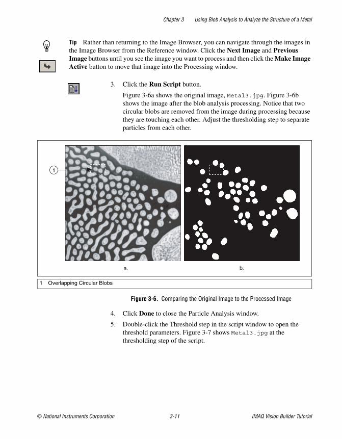
3. Click the Run Script button.
Figure 3-6a shows the original image, Metal3.jpg. Figure 3-6bshows the image after the blob analysis processing. Notice that twocircular blobs are removed from the image during processing becausethey are touching each other. Adjust the thresholding step to separateparticles from each other.
Figure 3-6. Comparing the Original Image to the Processed Image
4. Click Done to close the Particle Analysis window.
5. Double-click the Threshold step in the script window to open thethreshold parameters. Figure 3-7 shows Metal3.jpg at thethresholding step of the script.
1 Overlapping Circular Blobs
a. b.
1

Chapter 3 Using Blob Analysis to Analyze the Structure of a Metal
IMAQ Vision Builder Tutorial 3-12 ni.com
Figure 3-7. Testing the Blob Analysis Script
6. Adjust the minimum threshold value until the blobs are clearlyseparated. A minimum value of 150 works well.
7. Click Replace.
8. Click the Run Script button to rerun the script. Notice that only thecircular blobs now appear in the final processed image.
9. Click Done to close the Particle Analysis window.

Chapter 3 Using Blob Analysis to Analyze the Structure of a Metal
© National Instruments Corporation 3-13 IMAQ Vision Builder Tutorial
Saving the Blob Analysis ScriptNow that you have written a blob analysis algorithm and tested it onanother image, you can save the script to use on similar images. You alsocan perform batch processing with this script. See the Analyzing aCollection of Images with Batch Processing section in Chapter 4, UsingGauging for Part Inspection, for an example of batch processing inIMAQ Vision Builder.
1. Select Script»Save Script.
2. Save the script as blob analysis.scr.
Estimating Processing TimeIMAQ Vision Builder can estimate the time, in milliseconds, thatIMAQ Vision will take to process the active image with the open script.The Performance Meter gives both an estimate of the total time IMAQVision will take to process the image and an estimate of the time eachfunction within the script will require. Follow these steps to estimate howmany milliseconds IMAQ Vision will use to process Metal3.jpg withblob analysis.scr:
1. Select Script»Performance Meter. The Performance Meter gives anestimate of the total time IMAQ Vision will take to run the script.
2. Click Details to view an itemized list of the time IMAQ Vision willtake to perform each function in the script.
3. Click OK to close the Performance Meter.

Chapter 3 Using Blob Analysis to Analyze the Structure of a Metal
IMAQ Vision Builder Tutorial 3-14 ni.com
Creating a LabVIEW VIIMAQ Vision Builder features a wizard that creates the LabVIEW andIMAQ Vision VI for implementing the different steps of your script.Figure 3-8 shows the VI creation wizard.
Figure 3-8. LabVIEW VI Creation Wizard
Follow these steps to create your LabVIEW VI:
1. Select Script»Create LabVIEW VI.
Note If several versions of LabVIEW and IMAQ Vision are installed on your computer,the wizard searches your machine and displays a list of the available LabVIEW andIMAQ Vision versions you can use to create the VI. Select the target version of LabVIEWin the list, and click Next.
2. Select Current Script to create a VI that performs the algorithm youprototyped.
3. Select the Image Source and the Acquisition Type, then click Next.
4. Select Image File as the Image Source to create a VI to open an imagefrom your hard disk.

Chapter 3 Using Blob Analysis to Analyze the Structure of a Metal
© National Instruments Corporation 3-15 IMAQ Vision Builder Tutorial
5. Check the parameters that you want to appear as controls (inputs) andindicators (outputs) on the front panel of the created VI. Anyunchecked parameters are hard-coded as constants in the diagram.
6. Click Finish to create the VI.
Note You must have LabVIEW 6 or higher and IMAQ Vision 6 for LabVIEW or higherto use the LabVIEW VI creation features of IMAQ Vision Builder.

© National Instruments Corporation 4-1 IMAQ Vision Builder Tutorial
4Using Gaugingfor Part Inspection
This chapter describes gauging and provides step-by-step directions forprototyping a part inspection application in IMAQ Vision Builder.
What Is Gauging?Components such as connectors, switches, and relays are small andmanufactured in high quantity. Human inspection of these components istedious and time consuming. Vision systems can quickly and consistentlymeasure certain features on a component and generate a report with theresults. From the results, you can determine whether a part meets itsspecifications.
Gauging consists of making critical distance measurements—such aslengths, diameters, angles, and counts—to determine if the product ismanufactured correctly. If the gauged distance or count does not fall withintolerance limits, the component or part does not meet specifications andshould be rejected. Gauging inspection is used often in mechanicalassembly verification, electronic packaging inspection, containerinspection, glass vile inspection, and electronic connector inspection.
TutorialIn this tutorial, you analyze images of pipe brackets to see if the bracketsmeet their physical specifications. A pipe bracket is a metal piece ofhardware used to bolt down long, slender parts, such as a tube of bundledwires.
Your goal is to measure angles and distances between features on thebrackets and determine if those measurements fall within a tolerance range.Figure 4-1 illustrates the measurements and the acceptable values for thosemeasurements.

Chapter 4 Using Gauging for Part Inspection
IMAQ Vision Builder Tutorial 4-2 ni.com
Figure 4-1. Bracket Specifications
Width Center is the center of the bracket’s width. Width Center becomesthe vertex of Bracket Angle. Bracket Angle measures the angle of the armsof the bracket and determines if the bracket’s arms are aligned properly.Bracket Distance measures the length in pixels between two manufacturedholes in the bracket. Bracket Distance also determines whether thebracket’s arch is the appropriate height and curvature.
As you perform this analysis, IMAQ Vision Builder records all of theprocessing operations and parameters in a script. You will run that script onother bracket images to determine which are good and which are defective.
1 2
3
4
5
Edge 1
Edge 2
Bracket Distance362 to 368 pixels
Top View
Side View
Bracket Angle178 to 181 degrees Width Center

Chapter 4 Using Gauging for Part Inspection
© National Instruments Corporation 4-3 IMAQ Vision Builder Tutorial
Loading Images into IMAQ Vision BuilderPerform the following steps to load an image:
1. Launch IMAQ Vision Builder from the Start menu(Start»Programs»National Instruments IMAQ Vision Builder 6).
2. Select File»Open Image to load images.
3. Navigate to Program Files\National Instruments\IMAQ
Vision Builder 6\Examples\Bracket and check theSelect All Files option. IMAQ Vision Builder previews the images inthe Preview Image window and displays information about the fileformat, size, and type.
Tip The Preview Image window displays all selected images in a sequence. To viewthe images at a different rate, adjust the slide to the right of the Preview Image window.
4. Click OK to load the image files into IMAQ Vision Builder. From thiscollection of images in the Image Browser, you can select the imagethat you want to process.
5. Double click the first image, Bracket1.jpg, to load it into theprocessing window.
Finding Measurement Points Using Pattern MatchingBefore you can compute the measurements, you need to locate features onwhich you can base the measurements. In this example, you use patternmatching to find manufactured holes in a bracket. These holes serve asmeasurement points from which you can determine whether the bracket’sarch is the appropriate height and curvature.
1. Select Machine Vision»Pattern Matching. Make sure the LearnTemplate tab is selected.
2. With the Rectangle Tool, click and drag a box around the left hole inthe image, as shown in Figure 4-2. The selected area, or region ofinterest (ROI), will become the template pattern.

Chapter 4 Using Gauging for Part Inspection
IMAQ Vision Builder Tutorial 4-4 ni.com
Figure 4-2. Selecting a Template Pattern
3. Click Create from ROI to learn the selected area as the templatepattern. Learning the template takes a few seconds. AfterIMAQ Vision Builder learns the template, a save dialog box appears.
4. Navigate to Program Files\National Instruments\
IMAQ Vision Builder 6\Examples\Bracket.
5. Save the template as template.png. The Pattern Matching parameterwindow displays the template image and its path.
6. Select the Search Template tab.
7. Set Search Mode to Shift Invariant. Use shift-invariant matching whenyou do not expect the matches you locate to be rotated in their images.If you expect your matches to be rotated, use rotation-invariantmatching.
8. Check the Sub-Pixel Accuracy checkbox.
9. Set the Minimum Score to 600. A minimum score of 600 ensures thatIMAQ Vision Builder will find matches similar, but not identical, to thetemplate.
10. Set Number of Matches to 1.
11. With the Rectangle Tool, draw an ROI around the left side of thebracket, as shown in Figure 4-3. Be sure that the region you draw islarger than the template image and big enough to encompass allpossible locations of the template in the other images you will analyze.
Drawing a region of interest in which you expect to locate a templatematch is a significant step in pattern matching. It reduces the risk offinding a mismatch. It also allows you to specify the order in which youwant to locate multiple instances of a template in an image.

Chapter 4 Using Gauging for Part Inspection
© National Instruments Corporation 4-5 IMAQ Vision Builder Tutorial
Figure 4-3. Selecting the First Search Area
Once you draw the region of interest, IMAQ Vision Builderautomatically locates the template in the region and displays the scoreand location of the match. Notice that the score for the match is 1000.The score for this match is perfect because you made the template fromthe same region of the image.
12. Click Apply to add this step to the script.
13. With the Rectangle Tool, draw a region of interest around the rightside of the bracket, as shown in Figure 4-4. IMAQ Vision Builderautomatically locates the template in the region bound by the rectangleand displays the score and location of the match.
Figure 4-4. Selecting the Second Search Area
The score of the second match is not a perfect 1000, but it is highenough for you to consider it a match to the template.
14. Click Apply to add this step to the script.
15. Click Close.

Chapter 4 Using Gauging for Part Inspection
IMAQ Vision Builder Tutorial 4-6 ni.com
Finding Edges in the ImageBefore you can compute measurements to determine whether a bracketmeets specifications, you need to detect edges on which you can base themeasurements. The Edge Detector function finds edges along a line thatyou draw with the Line Tool from the Tools palette.
1. Select Machine Vision»Edge Detector.
2. Select the Advanced Edge Tool. The Advanced Edge Tool is effectiveon images with poor contrast between the background and objects.
3. Select First & Last Edge so that IMAQ Vision Builder finds andlabels only the first and last edges along the line you draw.
4. Set the Contrast to 40. The detection process only returns the first andlast edge whose contrast is greater than 40.
5. Click and drag to draw a vertical line across the middle of the bracketto find the edges that you can use to calculate Width Center, as shownin Figure 4-5. IMAQ Vision Builder labels the edges 1 and 2.
Tip To draw a straight line, press and hold the <Shift> key as you draw the line.
Figure 4-5. Finding the Edges for Bracket Distance
Look at the line profile. The sharp transitions in the line profile indicateedges. Notice that the number of edges found is displayed under theline profile.
6. Click Apply to add this edge detection step to the script.
7. Click Close to close the Edge Detector window.
1
2

Chapter 4 Using Gauging for Part Inspection
© National Instruments Corporation 4-7 IMAQ Vision Builder Tutorial
Taking the MeasurementsNow that you have found the bracket’s holes and the necessary edges, youcan calculate the center of the bracket’s width, distance between thebracket’s holes, and angle of the bracket’s arms with the caliper function.The caliper function is a tool that uses points on the image to calculatemeasurements—such as distances, angles, the center of a segment, or thearea—depending on the number of points you have selected on the image.These points are results of earlier processing steps, such as edge detectionsand pattern matching.
Follow these steps to make the measurements:
1. Select Machine Vision»Caliper.
2. In the image, click on points 3 and 4 to obtain the firstmeasurement—Width Center—which specifies the center of thebracket’s width.
Tip If you have trouble finding the points, click the Zoom In tool in the Tools palette tomagnify the image. Magnification factors are displayed in the lower, left corner of theprocessing window. 1/1 specifies 100% magnification (default). 2/1 specifies a slightlymagnified view, and 1/2 specifies a slightly demagnified view.
Tip Instead of clicking on the points in the image, you can double click on the points inthe Points list box to select them. When you select a point, IMAQ Vision Builder places acheck mark next to it.
3. Select Center from the Type of Measure list.

Chapter 4 Using Gauging for Part Inspection
IMAQ Vision Builder Tutorial 4-8 ni.com
4. Click the Measure button to compute the center of the bracket’s widthand add the Width Center measurement to the results table, as shownin Figure 4-6.
Figure 4-6. Using the Caliper Function to Find Width Center
5. Click Apply to add this step to the script.
6. Select Machine Vision»Caliper again. The center of the bracket’swidth appears as point 5.
7. Click on points 1 and 2 in the image to find the secondmeasurement—Bracket Distance—which measures the lengthbetween the manufactured holes in the bracket and determines whetherthe bracket’s arch is the appropriate height.
8. Select Distance from the Type of Measure list.
9. Click the Measure button to compute the distance between thebracket’s holes and add the measurement to the results table.
3
4
1 2–

Chapter 4 Using Gauging for Part Inspection
© National Instruments Corporation 4-9 IMAQ Vision Builder Tutorial
10. Click on points 1, 5, and 2 (in that order) to find the thirdmeasurement—Bracket Angle—which measures the angle of thebracket’s arms with respect to a vertex at point 5, as shown inFigure 4-7.
11. Select Angle from the Type of Measure list.
12. Click the Measure button to compute the angle of the bracket’s armsand add the measurement to the results table.
Figure 4-7 shows the image with Bracket Distance and Bracket Angleselected on the image and displayed in the results table.
Figure 4-7. Using the Caliper Tool to Collect Measurements
13. Click Apply to add these caliper measurements to the script and closethe caliper window.
14. Select Script»Save Script and save the script as bracket.scr.
3
4
1 25

Chapter 4 Using Gauging for Part Inspection
IMAQ Vision Builder Tutorial 4-10 ni.com
Analyzing a Collection of Images with Batch ProcessingPerform the following steps to run the script as a batch process onthe bracket images and generate a text file containing all of themeasurement data:
1. Select Script»Batch Processing.
2. Select Browser from Image Source to process the images stored in theImage Browser.
The listbox contains all of the steps in the script. You can select anystep in the script and choose options, such as saving that step’s resultsto file, displaying results, or opening the parameter window to adjustthe settings on each iteration. For this example, open the caliperparameter window and save the caliper results to a file.
3. Select the last caliper entry in the list box.
4. Check Open Results Panel and Save Results under Analysis Mode.
5. Click the Setup button and set the following options:
a. Select One file for all results.
b. Press the Browse button, navigate to the directory where you wantthe file saved, and click Select Cur Dir.
c. In the File Name Prefix box, type bracket.txt to give theresults files a consistent name.
6. Click OK to close the Setup options.
7. Click Run! to start the batch process.
As batch processing runs, a progress window appears on the left sideof the IMAQ Vision Builder window. The progress window displaysthe current process (acquiring an image or processing an image), thenumber of times the process has been completed, the starting time, andan estimation of the time remaining. If you ever need to stop a batchprocess, click the Cancel button.
Note Because you checked Open Results Panel when setting up the batch processingparameters, you must click the Done button after the script runs on each image.
8. When the batch processing completes, click OK.
9. Click Return to exit the Batch Processing window.
The bracket images have been processed and the caliper results stored in atext file.

Chapter 4 Using Gauging for Part Inspection
© National Instruments Corporation 4-11 IMAQ Vision Builder Tutorial
Analyzing the ResultsAs you implement this algorithm in your development environment usingthe LabVIEW VI creation feature or the Builder file, remember to includeyour analysis. For this example, you can use Microsoft Excel to quicklyanalyze the results.
Note To complete this part of the tutorial, you must have Microsoft Excel 97 or higherinstalled on your computer.
1. Launch Microsoft Excel.
2. Open bracket.txt from within Excel to view the results.
The results are labeled and listed in the order in which they appear in theImage Browser. In this case, images are listed from Bracket1.jpg toBracket6.jpg.
Table 4-1 lists the acceptable ranges for the bracket measurements and theactual values you might see for the bracket images. Notice that Bracket1,Bracket2, and Bracket3 are the only ones that meet the specifications.The bold values for the other brackets indicate which measurements causedthem to fail.
Note The results you see in Excel may not match the values in Table 4-1 exactly. However,the results you obtain should be close enough to the values in Table 4-1 so that Bracket1,Bracket2, and Bracket3 pass inspection, and Bracket4, Bracket5, and Bracket6
do not pass.
Table 4-1. Bracket Measurement Results
BracketNumber
Bracket Distance(acceptable range: 362–368 pixels)
Bracket Angle(acceptable range: 178°°°°–181°°°°)
Bracket 1 363.00 179.8
Bracket 2 364.00 180.3
Bracket 3 363.00 179.7
Bracket 4 349.00 178.5
Bracket 5 339.01 178.4
Bracket 6 359.03 174.8

© National Instruments Corporation A-1 IMAQ Vision Builder Tutorial
ATechnical Support Resources
Web SupportNational Instruments Web support is your first stop for help in solvinginstallation, configuration, and application problems and questions. Onlineproblem-solving and diagnostic resources include frequently askedquestions, knowledge bases, product-specific troubleshooting wizards,manuals, drivers, software updates, and more. Web support is availablethrough the Technical Support section of ni.com
NI Developer ZoneThe NI Developer Zone at ni.com/zone is the essential resource forbuilding measurement and automation systems. At the NI Developer Zone,you can easily access the latest example programs, system configurators,tutorials, technical news, as well as a community of developers ready toshare their own techniques.
Customer EducationNational Instruments provides a number of alternatives to satisfy yourtraining needs, from self-paced tutorials, videos, and interactive CDs toinstructor-led hands-on courses at locations around the world. Visit theCustomer Education section of ni.com for online course schedules,syllabi, training centers, and class registration.
System IntegrationIf you have time constraints, limited in-house technical resources, or otherdilemmas, you may prefer to employ consulting or system integrationservices. You can rely on the expertise available through our worldwidenetwork of Alliance Program members. To find out more about ourAlliance system integration solutions, visit the System Integration sectionof ni.com

Appendix A
IMAQ Vision Builder Tutorial A-2 ni.com
Worldwide SupportNational Instruments has offices located around the world to help addressyour support needs. You can access our branch office Web sites from theWorldwide Offices section of ni.com. Branch office Web sites provideup-to-date contact information, support phone numbers, e-mail addresses,and current events.
If you have searched the technical support resources on our Web site andstill cannot find the answers you need, contact your local office or NationalInstruments corporate. Phone numbers for our worldwide offices are listedat the front of this manual.

© National Instruments Corporation G-1 IMAQ Vision Builder Tutorial
Glossary
Prefix Meaning Value
p- pico- 10–12
n- nano- 10–9
µ- micro- 10– 6
m- milli- 10–3
k- kilo- 103
M- mega- 106
G- giga- 109
t- tera- 1012
Numbers/Symbols
3D Three-dimensional.
3D view Displays the light intensity of an image in a three-dimensional coordinatesystem, where the spatial coordinates of the image form two dimensionsand the light intensity forms the third dimension.
A
area A rectangular portion of an acquisition window or frame that is controlledand defined by software.
area threshold Detects objects based on their size, which can fall within a user-specifiedrange.
arithmetic operators The image operations multiply, divide, add, subtract, and remainder.

Glossary
IMAQ Vision Builder Tutorial G-2 ni.com
B
b Bit. One binary digit, either 0 or 1.
B Byte. Eight related bits of data, an eight-bit binary number. Also denotesthe amount of memory required to store one byte of data.
binary image An image in which the objects usually have a pixel intensity of 1 (or 255)and the background has a pixel intensity of 0.
binary morphology Functions that perform morphological operations on a binary image.
binary threshold Separation of an image into objects of interest (assigned a pixel value of 1)and background (assigned pixel values of 0) based on the intensities of theimage pixels.
bit depth The number of bits (n) used to encode the value of a pixel. For a given n, apixel can take 2n different values. For example, if n equals 8-bits, a pixelcan take 256 different values ranging from 0 to 255. If n equals 16 bits, apixel can take 65,536 different values ranging from 0 to 65,535 or -32,768to 32,767.
blob Binary large object. A connected region or grouping of pixels in an imagein which all pixels have the same intensity level.
blob analysis A series of processing operations and analysis functions that produce someinformation about the blobs in an image.
blurring Reduces the amount of detail in an image. Blurring commonly occursbecause the camera is out of focus. You can blur an image intentionally byapplying a lowpass frequency filter.
BMP Bitmap. Image file format commonly used for 8-bit and color images(extension BMP).
border function Removes objects (or particles) in a binary image that touch the imageborder.
brightness (1) A constant added to the red, green, and blue components of a color pixelduring the color decoding process. (2) The perception by which whiteobjects are distinguished from gray and light objects from dark objects.

Glossary
© National Instruments Corporation G-3 IMAQ Vision Builder Tutorial
C
caliper (1) A function in IMAQ Vision Builder that calculates distances, angles,circular fits, and the center of mass based on positions given by edgedetection, particle analysis, centroid, and search functions. (2) Ameasurement function that finds edge pairs along a specified path in theimage. This function performs an edge extraction and then finds edge pairsbased on specified criteria such as the distance between the leading andtrailing edges, edge contrasts, and so forth.
chroma The color information in a video signal.
chrominance See chroma.
circle function Detects circular objects in a binary image.
closing A dilation followed by an erosion. A closing fills small holes in objects andsmooths the boundaries of objects.
color images Images containing color information, usually encoded in the RGB form.
contrast A constant multiplication factor applied to the luma and chromacomponents of a color pixel in the color decoding process.
convolution kernel 2D matrices (or templates) used to represent the filter in the filteringprocess. The contents of these kernels are a discrete two-dimensionalrepresentation of the impulse response of the filter that they represent.
D
default setting A default parameter value recorded in the driver. In many cases, the defaultinput of a control is a certain value (often 0).
definition The number of values a pixel can take on, which is the number of colors orshades that you can see in the image.
digital image An image f (x, y) that has been converted into a discrete number of pixels.Both spatial coordinates and brightness are specified.
dilation Increases the size of an object along its boundary and removes tiny holes inthe object.
driver Software that controls a specific hardware device, such as an IMAQ orDAQ device.

Glossary
IMAQ Vision Builder Tutorial G-4 ni.com
E
edge Defined by a sharp change (transition) in the pixel intensities in an imageor along an array of pixels.
edge contrast The difference between the average pixel intensity before and the averagepixel intensity after the edge.
edge detection Any of several techniques to identify the edges of objects in an image.
edge steepness The number of pixels that corresponds to the slope or transition area of anedge.
erosion Reduces the size of an object along its boundary and eliminates isolatedpoints in the image.
F
fiducial A reference pattern on a part that helps a machine vision application findthe part's location and orientation in an image.
function A set of software instructions executed by a single line of code that mayhave input and/or output parameters and returns a value when executed.
G
gauging Measurement of an object or distances between objects.
grayscale image An image with monochrome information.
grayscale morphology Functions that perform morphological operations on a grayscale image.
H
histogram Indicates the quantitative distribution of the pixels of an image pergray-level value.
hole filling function Fills all holes in objects that are present in a binary image.
HSI Color encoding scheme in Hue, Saturation, and Intensity.

Glossary
© National Instruments Corporation G-5 IMAQ Vision Builder Tutorial
HSL Color encoding scheme using Hue, Saturation, and Luminance informationwhere each image in the pixel is encoded using 32 bits: 8 bits for hue, 8 bitsfor saturation, 8 bits for luminance, and 8 unused bits.
HSV Color encoding scheme in Hue, Saturation, and Value.
hue Represents the dominant color of a pixel. The hue function is a continuousfunction that covers all the possible colors generated using the R, G, and Bprimaries. See also RGB.
I
I/O Input/output. The transfer of data to/from a computer system involvingcommunications channels, operator interface devices, and/or dataacquisition and control interfaces.
image A two-dimensional light intensity function f (x, y) where x and y denotespatial coordinates and the value f at any point (x, y) is proportional to thebrightness at that point.
image border A user-defined region of pixels surrounding an image. Functions thatprocess pixels based on the value of the pixel neighbors require imageborders.
Image Browser An image that contains thumbnails of images to analyze or process in avision application.
image definition See pixel depth.
image enhancement The process of improving the quality of an image that you acquire from asensor in terms of signal-to-noise ratio, image contrast, edge definition, andso on.
image file A file containing pixel data and additional information about the image.
image format Defines how an image is stored in a file. Usually composed of a headerfollowed by the pixel data.
image palette The gradation of colors used to display an image on screen, usually definedby a color lookup table.
image processing Encompasses various processes and analysis functions that you can applyto an image.

Glossary
IMAQ Vision Builder Tutorial G-6 ni.com
image source Original input image.
image visualization The presentation (display) of an image (image data) to the user.
imaging Any process of acquiring and displaying images and analyzing image data.
IMAQ Image Acquisition.
inspection The process by which parts are tested for simple defects such as missingparts or cracks on part surfaces.
inspection function Analyzes groups of pixels within an image and returns information aboutthe size, shape, position, and pixel connectivity. Typical applicationsinclude quality of parts, analyzing defects, locating objects, and sortingobjects.
instrument driver A set of high-level software functions, such as NI-IMAQ, that controlspecific plug-in computer boards. Instrument drivers are available inseveral forms, ranging from a function callable from a programminglanguage to a virtual instrument (VI) in LabVIEW.
intensity The sum of the Red, Green, and Blue primary colors divided by three.(Red+Green+Blue)/3
intensity profile The gray-level distribution of the pixels along an ROI in an image.
intensity range Defines the range of gray-level values in an object of an image.
intensity threshold Characterizes an object based on the range of gray-level values in theobject. If the intensity range of the object falls within the user-specifiedrange, it is considered an object. Otherwise it is considered part of thebackground.
J
JPEG Joint Photographic Experts Group. Image file format for storing 8-bit andcolor images with lossy compression (extension JPG).
K
kernel Structure that represents a pixel and its relationship to its neighbors.The relationship is specified by weighted coefficients of each neighbor.

Glossary
© National Instruments Corporation G-7 IMAQ Vision Builder Tutorial
L
labeling The process by which each object in a binary image is assigned a uniquevalue. This process is useful for identifying the number of objects in theimage and giving each object a unique identity.
LabVIEW Laboratory Virtual Instrument Engineering Workbench. Programdevelopment environment application based on the programming languageG used commonly for test and measurement applications.
line profile Represents the gray-level distribution along a line of pixels in an image.
logic operators The image operations AND, NAND, OR, XOR, NOR, XNOR, difference,mask, mean, max, and min.
luma The brightness information in the video picture. The luma signal amplitudevaries in proportion to the brightness of the video signal and correspondsexactly to the monochrome picture.
luminance See luma.
M
M (1) Mega, the standard metric prefix for 1 million or 106, when used withunits of measure such as volts and hertz (2) Mega, the prefix for 1,048,576,or 220, when used with B to quantify data or computer memory.
machine vision An automated application that performs a set of visual inspection tasks.
match score A number ranging from 0 to 1000 that indicates how closely an acquiredimage matches the template image. A match score of 1000 indicates aperfect match. A match score of 0 indicates no match.
MB Megabyte of memory.
MMX Multimedia Extensions. Intel chip-based technology that allows paralleloperations on integers, which results in accelerated processing of 8-bitimages.

Glossary
IMAQ Vision Builder Tutorial G-8 ni.com
morphologicaltransformations
Extract and alter the structure of objects in an image. You can use thesetransformations for expanding (dilating) or reducing (eroding) objects,filling holes, closing inclusions, or smoothing borders. They are usedprimarily to delineate objects and prepare them for quantitative inspectionanalysis.
N
neighbor A pixel whose value affects the value of a nearby pixel when an image isprocessed. The neighbors of a pixel are usually defined by a kernel or astructuring element.
neighborhoodoperations
Operations on a point in an image that take into consideration the values ofthe pixels neighboring that point.
NI-IMAQ Driver software for National Instruments IMAQ hardware.
O
opening An erosion followed by a dilation. An opening removes small objects andsmooths boundaries of objects in the image.
operators Allow masking, combination, and comparison of images. You can usearithmetic and logic operators in IMAQ Vision.
P
palette The gradation of colors used to display an image on screen, usually definedby a color lookup table.
pattern matching The technique used to locate quickly a grayscale template within agrayscale image
picture element An element of a digital image. Also called pixel.
pixel Picture element. The smallest division that makes up the video scan line.For display on a computer monitor, a pixel's optimum dimension is square(aspect ratio of 1:1, or the width equal to the height).

Glossary
© National Instruments Corporation G-9 IMAQ Vision Builder Tutorial
pixel aspect ratio The ratio between the physical horizontal size and the vertical size of theregion covered by the pixel. An acquired pixel should optimally be square,thus the optimal value is 1.0, but typically it falls between 0.95 and 1.05,depending on camera quality.
pixel depth The number of bits used to represent the gray level of a pixel.
PNG Portable Network Graphic. Image file format for storing 8-bit, 16-bit, andcolor images with lossless compression (extension PNG).
proper-closing A finite combination of successive closing and opening operations that youcan use to fill small holes and smooth the boundaries of objects.
proper-opening A finite combination of successive opening and closing operations that youcan use to remove small particles and smooth the boundaries of objects.
pts Points.
Q
quantitative analysis Obtaining various measurements of objects in an image.
R
resolution The number of rows and columns of pixels. An image composed of m rowsand n columns has a resolution of m×n.
RGB Color encoding scheme using red, green, and blue (RGB) color informationwhere each pixel in the color image is encoded using 32 bits: 8 bits for red,8 bits for green, 8 bits for blue, and 8 bits for the alpha value (unused).
ROI Region of interest. (1) An area of the image that is graphically selectedfrom a window displaying the image. This area can be used focus furtherprocessing. (2) A hardware-programmable rectangular portion of theacquisition window.
ROI tools Collection of tools from the Lab VIEW Tools palette that enable you toselect a region of interest from an image. These tools let you select a pointor line; polygon, rectangle, and oval regions; and freehand lines and areas.
rotation-invariantmatching
A pattern matching technique in which the reference pattern can be locatedat any orientation in the test image as well as rotated at any degree.

Glossary
IMAQ Vision Builder Tutorial G-10 ni.com
S
saturation The amount of white added to a pure color. Saturation relates to the richnessof a color. A saturation of zero corresponds to a pure color with no whiteadded. Pink is a red with low saturation.
scale-invariantmatching
A pattern matching technique in which the reference pattern can be any sizein the test image.
shift-invariantmatching
A pattern matching technique in which the reference pattern can be locatedanywhere in the test image but cannot be rotated or scaled.
smoothing filter Blurs an image by attenuating variations of light intensity in theneighborhood of a pixel.
sub-pixel analysis Finds the location of the edge coordinates in terms of fractions of a pixel.
T
template Color, shape, or pattern that you are trying to match in an image using thecolor matching, shape matching, or pattern matching functions. A templatecan be a region selected from an image or it can be an entire image.
threshold Separates objects from the background by assigning all pixels withintensities within a specified range to the object and the rest of the pixels tothe background. In the resulting binary image, objects are represented witha pixel intensity of 255 and the background is set to 0.
threshold interval Two parameters, the lower threshold gray-level value and the upperthreshold gray-level value.
TIFF Tagged Image File Format. Image format commonly used for encoding8-bit, 16-bit, and color images (extension TIF).
Tools palette Collection of tools that enable you to select regions of interest, zoom in andout, and change the image palette.

Glossary
© National Instruments Corporation G-11 IMAQ Vision Builder Tutorial
V
value The grayscale intensity of a color pixel computed as the average of themaximum and minimum red, green, and blue values of that pixel.
VI Virtual Instrument. (1) A combination of hardware and/or softwareelements, typically used with a PC, that has the functionality of a classicstand-alone instrument (2) A LabVIEW software module (VI), whichconsists of a front panel user interface and a block diagram program.

© National Instruments Corporation I-1 IMAQ Vision Builder Tutorial
Index
Numerics3D view, 1-4
Aacquiring images
grab (continuous image), 2-11opening the Interface window, 2-8, 3-2region of interest, 2-11sequence, 2-11snap (single image), 2-10
acquisition typesgrab, 2-7sequence, 2-7snap, 2-7
Acquisition window, 1-3opening, 2-8
acquisiton modules, 2-8advanced edge tool, 4-6analyzing blobs, 3-10
Bbatch processing, 1-3, 4-10binary morphology, 1-6binary processing and analysis functions, 1-6
circle detection, 1-6invert binary image, 1-6particle analysis, 1-6
blob, 3-1blob analysis
analyzing circular blobs, 3-10definition, 3-1estimating processing time, 3-13examining image, 3-3filtering, 3-5introduction, 3-1
isolating circular blobs, 3-9modifying blobs with morphological
functions, 3-8morphology, 3-8opening images, 3-2overview, 3-1particle analysis, 3-10particle filter, 3-9preparing images for processing, 3-2 to 3-5saving the script, 3-13separating particles from background, 3-6testing the script, 3-10thresholding, 3-6
Browser. See Image BrowserBuilder file, 4-11
Ccalibration from image, 1-7calibration functions, 1-7
calibration from image, 1-7grid calibration, 1-7image correction, 1-7simple calibration, 1-7
caliper, 1-6, 4-7 to 4-9centroid, 1-5Choose Measurements button, 3-10circle detection, 1-6circular blobs
analyzing, 3-10isolating, 3-9
clamp, 1-6closing IMAQ Vision Builder, 1-2color image processing functions, 1-5
color location, 1-5color matching, 1-5color operators, 1-5

Index
IMAQ Vision Builder Tutorial I-2 ni.com
color pattern matching, 1-5color plane extraction, 1-5color threshold, 1-5
color location, 1-5color matching, 1-5color operators, 1-5color pattern matching, 1-5color plane extraction, 1-5color threshold, 1-5continuous acquisition (grabbing
images), 2-11conventions used in manual, ivcreating a LabVIEW VI, 3-14customer education, A-1
Ddocumentation
conventions used in manual, ivIMAQ Vision manuals, 1-8
Eedge detection, 1-6edge detector, 4-6edges, finding in image, 4-6exiting IMAQ Vision Builder, 1-2
Ffeatures of IMAQ Vision Builder, 1-3fill holes, 3-8filtering, 1-5filtering images, 3-5find circular edge, 1-6find straight edge, 1-6finding edges, 4-6full-size view (Image Browser), 2-2
functionsbinary processing and analysis
functions, 1-6calibration functions, 1-7color image processing functions, 1-5grayscale image processing functions, 1-5image analysis functions, 1-4machine vision functions, 1-6morphological functions, 3-8
Ggauging
analyzing results, 4-11batch processing, 4-10bracket specifications (figure), 4-2definition, 4-1finding edges, 4-6finding measurement points using pattern
matching, 4-3introduction, 4-1loading images, 4-3making measurements, 4-7 to 4-9overview, 4-1
getting help, 1-7getting started in IMAQ Vision Builder,
2-1 to 2-7grab, 2-7grabbing images (continuous
acquisition), 2-11grayscale image processing and analysis
functions, 1-5centroid, 1-5quantify, 1-5
grayscale morphology, 1-5grid calibration, 1-7

Index
© National Instruments Corporation I-3 IMAQ Vision Builder Tutorial
Hhelp
IMAQ Vision Builder scripts, 1-9IMAQ Vision documentation, 1-8National Instruments Web site, 1-8online help, 1-7
Heywood Circularity Factor particle filter, 3-9histogram, 1-4, 2-4, 3-6
in Threshold parameter window, 2-4
Iimage acquisition, 2-7image acquisition. See acquiring imagesimage analysis functions, 1-4
3D view, 1-4histogram, 1-4line profile, 1-4
Image Browseraccessing from the toolbar, 3-11definition, 1-3full-size view, 2-2important elements (figure), 2-2thumbnail view, 2-2
image correction, 1-7image processing
entering processing mode, 2-3getting started in IMAQ Vision Builder,
2-1 to 2-7thresholding images, 2-5
imagesloading
for blob analysis, 2-3for gauging, 4-3for image processing, 2-3
opening in IMAQ Vision Builder, 2-1IMAQ hardware, 1-1, 2-7
IMAQ Vision Builderacquiring images, 2-7 to 2-12binary processing and analysis
functions, 1-6calibration functions, 1-7color image processing functions, 1-5environment, 1-3exiting, 1-2features, 1-3getting help, 1-7getting started, 2-1 to 2-7grayscale image processing and analysis
functions, 1-5image analysis functions, 1-4installing, 1-2using with LabVIEW, 3-10using with LabWindows/CVI, 3-10launching, 1-2machine vision functions, 1-6online help, 1-7sending data to Microsoft Excel, 4-11system requirements, 1-1using with Microsoft Excel, 3-10using with Visual Basic, 3-10
IMAQ Vision documentation, 1-8installing IMAQ Vision Builder, 1-2Interface window (acquisition), 1-3Interfaces window, 2-8invert binary image, 1-6isolating circuar blobs, 3-9
LLabVIEW, 3-10LabVIEW VI creation, 1-4, 4-11LabVIEW VI creation wizard, 3-14LabWindows/CVI, 3-10launching IMAQ Vision Builder, 1-2line profile, 1-4, 3-3, 4-6line tool, 3-3

Index
IMAQ Vision Builder Tutorial I-4 ni.com
loading imagesblob analysis, 3-2gauging, 4-3image processing, 2-3
lookup tables, 1-5
Mmachine vision functions, 1-6
caliper, 1-6clamp, 1-6edge detection, 1-6find circular edge, 1-6find straight edge, 1-6pattern matching, 1-6
magnifying an image, 4-7manuals for IMAQ Vision, 1-8Measurement & Automation Explorer
(MAX), 2-7measurements for gauging. See gaugingMicrosoft Excel, using with IMAQ Vision
Builder, 3-10, 4-11morphology, 3-8
NNational Instruments Web site, 1-8National Instruments Web support, A-1NI Developer Zone, A-1NI-IMAQ, 1-1, 2-7
Oonline help, 1-7opening images, 2-1, 3-2, 4-3operators, 1-5
PParameter window, 1-4part inspection, 4-1
particle analysis, 1-6, 3-10particle filter, 3-9particle filtering, 1-6particles, separating from background with
thresholding, 3-6pattern matching, 1-6pattern matching for finding measurement
points, 4-3Performance Meter, 1-4, 3-13Preview Image window, 3-2, 4-3processing mode, 2-3Processing window, 1-4, 2-3
Qquantify, 1-5
RReference window
definition, 1-4purpose, 2-3using to browse images, 3-11
remove border objects, 3-8Run Script button, 2-7, 3-11, 3-12
Sscripting
batch processing, 4-10description, 1-3using example scripts, 1-9modifying scripts, 3-12opening scripts, 2-7Run Script button, 2-7, 3-11, 3-12saving scripts, 2-7, 3-13Script window, 1-3, 2-6testing scripts, 3-10

Index
© National Instruments Corporation I-5 IMAQ Vision Builder Tutorial
scriptsblob analysis script
recording, 3-1saving, 3-13testing, 3-10
gauging scriptanalyzing collection of images, 4-10saving, 4-9
sample scripts, 1-9thresholding script, 2-7
Select All Files option, 3-2, 4-3Send Data to Excel button, 3-10separating particles from background, 3-6sequence, 2-7sequence acquisition, 2-11Show Labels option, 3-10simple calibration, 1-7simulation module, 2-10, 2-11snap, 2-7snapping one image (single acquisition), 2-10Solution Wizard, 1-4starting IMAQ Vision Builder, 1-2system integration, by National
Instruments, A-1system requirements, 1-1
Ttaking measurements, 4-7technical support resources, A-1testing scripts, 3-10threshold, 1-5Threshold parameter window, 2-4thresholding
manual threshold, 2-4, 3-6modifying threshold parameters, 3-11procedure, 2-4separating particles from background, 3-6
thumbnail view (Image Browser), 2-2Tools Palette, 1-4
trigger, 2-10tutorials
blob analysis, 3-1gauging, 4-1
Uusing the caliper function, 4-7
VVisual Basic, 3-10
WWeb support from National Instruments, A-1
getting help for IMAQ Vision, 1-8windows
Acquisition, 1-3Parameter, 1-4Processing, 1-4, 2-3Reference, 1-4, 2-3, 3-11Script, 1-3, 2-6
worldwide technical support, A-2
ZZoom In tool, 4-7