Embed Size (px)
Citation preview
ARDOP: A Versatile Humanoid Robotic Research PlatformSudarshan S HarithasBMS College of EngineeringBangalore, Karnataka, [email protected]
Harish V MekaliBMS College of EngineeringBangalore, Karnataka, India
ABSTRACTThis paper describes the development of a humanoid robot calledARDOP. The goal of the project is to provide amodular, open-source,and inexpensive humanoid robot that would enable researchersto answer various problems related to robotic manipulation andperception. ARDOP primarily comprises of two functional unitsnamely the perception and manipulation system, here we discussthe conceptualization and design methodology of these systemsand proceed to present their performance results on simulationand various custom-designed experiments. The project has beenmaintained on our page https://ardop.github.io/.
KEYWORDSHumanoid Robot, robotic manipulator design, object manipulation,kinematics, Perception
1 INTRODUCTIONThe multidisciplinary research community has been increasinglyfocusing on developing robots that can assist and perform activ-ities with humans in the loop. To serve the increase in attention,a robust modular research platform that can aid in rapid testingand software development, while being affordable, simple to recon-figure is of prime importance. Here we present Autonomous RobotDevelopment Open Source Platform (ARDOP) a robot that intends toaccelerate research primarily in the domains of manipulation [1],and perception [2] [3]. The robot is depicted in Fig. 1
At the core ARDOP consists of two functional units namely theperception and manipulation system . A calibrated RGBD MicrosoftKinect camera [4] and the pan-tilt joint of the neck form the per-ception system, the manipulation system includes a pair of 6DOFrobotic manipulators and its corresponding control system. A de-tailed description of the conceptualization, design, and developmentof individual systems has been presented in this paper. Furthermore,we present the ARDOP arm where the manipulator is constructedconsidering the workspace and torque constraints. Additionally,we evaluate the independent and coordinated performance of thesesystems through a series of experiments such as workspace awareobject manipulation and Tic-Tac-Toe.
Research across industry and academia have resulted in a few ofthe finest robots such as PR2 [5] , Robot Cosero [6],Intel HERB[7],Armar III [8], Pepper [9], bipedal robots such as ASIMO [10] ,ASIMO [10], and Petman [11], Atlas [12] form another class ofhumanoid robots. These robots have helped to expedite researchbut despite their impressive performance and encouraging resultsthey are very expensive for purchase and only a few of them areopen source but are difficult to replicate. Whereas all the hardware
, ,.
designs and software packages of ARDOP have been made availableopen-source and it can be replicated within $1000.
Our contribution can be summarized as follows:(1) Development of a robust, modular, inexpensive humanoid ro-
bot and open-source of its design files and software packagesthat can be easily reproduced.
(2) Formulation and design of 6DOF robotic manipulator con-sidering workspace and torque constraints. The arm canperform object manipulation to sub-centimeter range accu-racy.
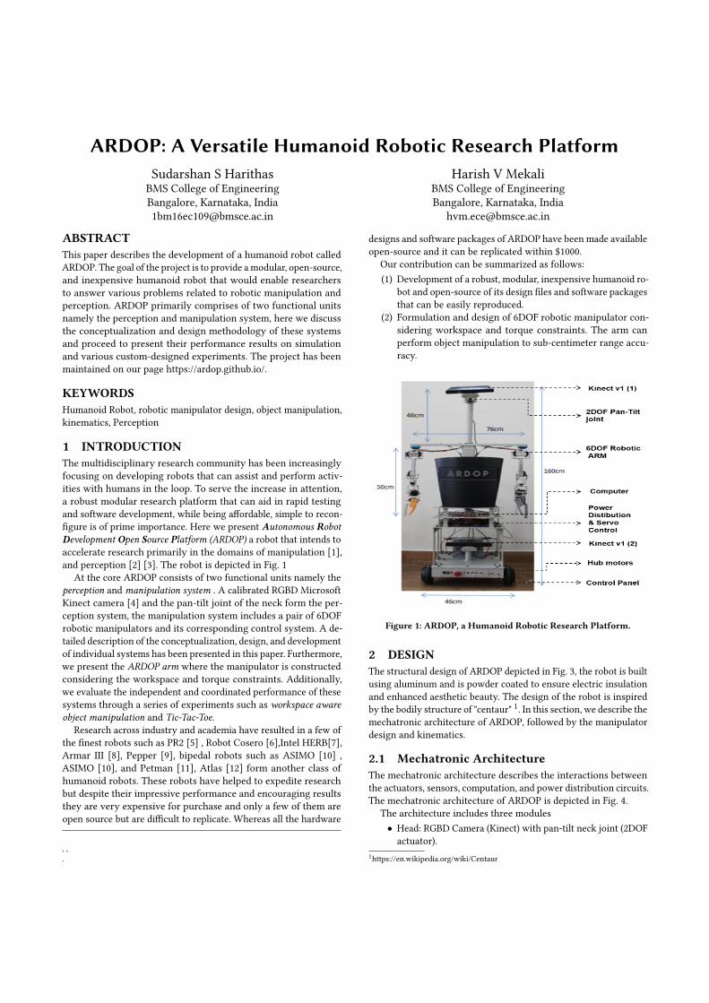
Figure 1: ARDOP, a Humanoid Robotic Research Platform.
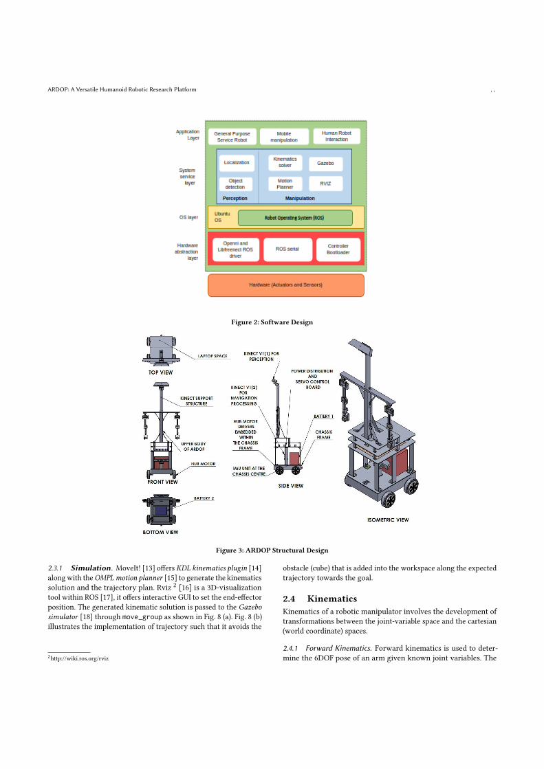
2 DESIGNThe structural design of ARDOP depicted in Fig. 3, the robot is builtusing aluminum and is powder coated to ensure electric insulationand enhanced aesthetic beauty. The design of the robot is inspiredby the bodily structure of "centaur" 1. In this section, we describe themechatronic architecture of ARDOP, followed by the manipulatordesign and kinematics.
2.1 Mechatronic ArchitectureThe mechatronic architecture describes the interactions betweenthe actuators, sensors, computation, and power distribution circuits.The mechatronic architecture of ARDOP is depicted in Fig. 4.
The architecture includes three modules• Head: RGBD Camera (Kinect) with pan-tilt neck joint (2DOFactuator).
1https://en.wikipedia.org/wiki/Centaur
, , Sudarshan S Harithas and Harish V Mekali
• Arm: a pair of 6DOF manipulators.• Upper Base: Housing for computer, drivers, power supplyunits, and controllers.
A 12V 60Ah battery connects to the power distribution and servocontrol board and powers the manipulation and the perception sys-tems of ARDOP. The power supply is secured and monitored bythe safety circuits and power meter respectively. The manipulationsystem consists of two 6DOF arms which are controlled using theArduino Mega development board and the perception system con-sists of a Kinect camera and a 2DOF pan-tilt joint. Furthermore,ARDOP has a tall neck of length 46𝑐𝑚, which places the camera atan optimal viewing position, additionally, it helps to counter theblind spot in the depth image of the Kinect camera. The laptop withIntel i5-6200U CPU with 16 GB RAM and a 1 TB HDD is housed inthe upper base performs the computation and inter-system coordi-nation.
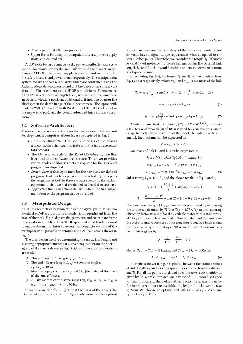
2.2 Software ArchitectureThe modular software stack allows for simple user interface anddevelopment, it comprises of four layers as depicted in Fig. 2
• Hardware Abstraction The layer comprises of the driversand controllers that communicate with the hardware actua-tors/sensors.
• The OS layer consists of the Robot Operating System thatis central to the software architecture. This layer providesvarious tools and libraries that are required for the user levelprogram development.
• System Service this layer includes the various user definedprograms that can be deployed on the robot. Fig. 2 depictsthe program stack of the three systems specific to the variousexperiments that we had conducted as detailed in section 3.
• Application this is an actionable layer where the final imple-mentation of the program can be observed.
2.3 Manipulator DesignARDOP is geometrically symmetric in the sagittal plane. It has twoidentical 6 DoF arms with its shoulder joint equidistant from thebase of the neck. Fig. 5, depicts the geometric and coordinate framerepresentation of ARDOP. A 3DOF spherical wrist has been usedto enable the manipulator to access the complete volume of theworkspace in all possible orientations, the ARDOP arm is shown inFig. 6.
The arm design involves determining the mass, link length andselecting appropriate motors for a given payload. From the stick di-agram of the arm is shown in Fig. 6(a), the following considerationsare made:
(1) The arm length 𝐿1 + 𝐿2 + 𝐿𝑒𝑒 𝑓 = 50𝑐𝑚.(2) The end-effector length 𝐿𝑒𝑒 𝑓 = 8𝑐𝑚, this implies
𝐿1 + 𝐿2 = 42𝑐𝑚.(3) Maximum payload mass𝑚𝑝 = 0.2𝑘𝑔 (inclusive of the mass
of the end-effector).(4) All six motors of the same mass (𝑚), 𝑚𝑠0 = 𝑚𝑠1 = 𝑚𝑠2 =
𝑚𝑠3 =𝑚𝑠4 =𝑚𝑠5 =𝑚 = 0.064𝑘𝑔.It can be observed from Fig. 6, that the mass of the arm is dis-
tributed along the axis of motor 𝑆0, which decreases its required
torque. Furthermore, we can interpret that motors at joints 𝑆1 and𝑆2 would have a higher torque requirement when compared to mo-tors at other joints. Therefore, we consider the torque 𝑇1 (of motor𝑆1) and 𝑇2 (of motor 𝑆2) to constrain and obtain the optimal linklength 𝐿1 and 𝐿2, that would enable the arm to access maximumworkspace volume.
Considering Fig. 6(a), the torque 𝑇1 and 𝑇2 can be obtained fromEq. 1 and 2 respectively, where𝑚𝐿1 and𝑚𝐿2 is the mass of the link.
𝑇1 =𝑚𝐿1 (𝐿12 ) +𝑚(𝐿1) +𝑚𝐿2 (𝐿1 +
𝐿22 ) + 3𝑚(𝐿1 + 𝐿2)
+𝑚𝑝 (𝐿1 + 𝐿2 + 𝐿𝑒𝑒 𝑓 ) (1)
𝑇2 =𝑚𝐿2 (𝐿22 ) + 3𝑚(𝐿2) +𝑚𝑝 (𝐿2 + 𝐿𝑒𝑒 𝑓 ) (2)
An aluminium sheet with density (𝐷) = 2.7×10⁻³ 𝐾𝑔𝑐𝑚3 , thickness
(H) 0.3𝑐𝑚 and breadth (B) of 12𝑐𝑚 is used for arm design. Consid-ering the rectangular structure of the sheet, the volume of link L1and L2, their volume can be expressed as,
𝑉 = 𝐿1,2 × 12 × 0.3
and mass of link L1 and L2 can be expressed as,
𝑀𝑎𝑠𝑠 (𝑀) = 𝐷𝑒𝑛𝑠𝑖𝑡𝑦 (𝐷) ×𝑉𝑜𝑙𝑢𝑚𝑒 (𝑉 )
𝑚(𝐿1,2) = 2.7 × 10−3 × 12 × 0.3 × 𝐿1,2
𝑚(𝐿1,2) = 9.72 × 10⁻³ × 𝐿1,2 = 𝐾 × 𝐿1,2 (3)Substituting 𝐿2 = 42 − 𝐿1 and the above results in Eq. 1 and 2,
𝑇1 =𝑚𝐿1 + 𝑘 (422)2 + 3𝑚(42) + 0.2(50) (4)
𝑇2 =𝐾 (42 − 𝐿1)2
2 + 3𝑚(42 − 𝐿1) + 0.2(42 − 𝐿1 + 8) (5)
The worst-case torque (𝑇1,2𝑤𝑐 ) analysis is performed by increasingthe torque requirement by 75% i.e.𝑇1,2 = 1.75×𝑇1,2 and consideringefficiency factor (𝜂 = 0.7) for the available motor with a stall torqueof 35𝐾𝑔.𝑐𝑚. Twomotors are used in the shoulder joint 𝑆1 to increasethe stability and robustness of the arm, moreover, this implies thatthe effective torque at joint 𝑆1 is 70𝐾𝑔.𝑐𝑚. The worst-case analysisfactor (𝛽) is given by,
𝛽 =𝜂
1.75 =0.71.75 = 0.4
Hence, 𝑇1𝑤𝑐 = 70𝛽 = 28𝐾𝑔.𝑐𝑚, and 𝑇2𝑤𝑐 = 35𝛽 = 14𝐾𝑔.𝑐𝑚.
𝑇1 < 𝑇1𝑤𝑐 𝑎𝑛𝑑 𝑇2 < 𝑇2𝑤𝑐 (6)
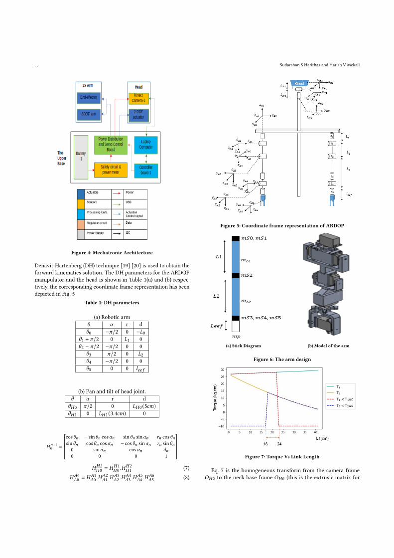
A graph as shown in Fig. 7 is plotted between the various valuesof link length 𝐿1 and its corresponding expected torque values 𝑇1and𝑇2. For all the points that do not obey the worst case condition asgiven by Eq. 6 are eliminated and a value of "−10" would assignedto them indicating their elimination. From the graph it can befurther inferred that the available link length 𝐿1 is between 16𝑐𝑚to 24𝑐𝑚. We choose an optimal and safe value of 𝐿1 = 20𝑐𝑚 and𝐿2 = 42 − 𝐿1 = 22𝑐𝑚.
ARDOP: A Versatile Humanoid Robotic Research Platform , ,
Figure 2: Software Design
Figure 3: ARDOP Structural Design
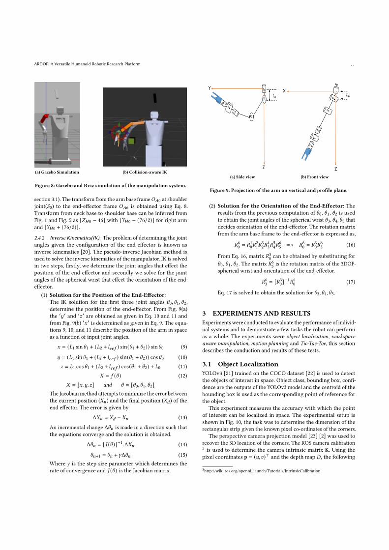
2.3.1 Simulation. MoveIt! [13] offers KDL kinematics plugin [14]alongwith theOMPLmotion planner [15] to generate the kinematicssolution and the trajectory plan. Rviz 2 [16] is a 3D-visualizationtool within ROS [17], it offers interactive GUI to set the end-effectorposition. The generated kinematic solution is passed to the Gazebosimulator [18] through move_group as shown in Fig. 8 (a). Fig. 8 (b)illustrates the implementation of trajectory such that it avoids the
2http://wiki.ros.org/rviz
obstacle (cube) that is added into the workspace along the expectedtrajectory towards the goal.
2.4 KinematicsKinematics of a robotic manipulator involves the development oftransformations between the joint-variable space and the cartesian(world coordinate) spaces.
2.4.1 Forward Kinematics. Forward kinematics is used to deter-mine the 6DOF pose of an arm given known joint variables. The
, , Sudarshan S Harithas and Harish V Mekali
Figure 4: Mechatronic Architecture
Denavit-Hartenberg (DH) technique [19] [20] is used to obtain theforward kinematics solution. The DH parameters for the ARDOPmanipulator and the head is shown in Table 1(a) and (b) respec-tively, the corresponding coordinate frame representation has beendepicted in Fig. 5
Table 1: DH parameters
(a) Robotic arm𝜃 𝛼 r d𝜃0 −𝜋/2 0 −𝐿0
𝜃1 + 𝜋/2 0 𝐿1 0𝜃2 − 𝜋/2 −𝜋/2 0 0
𝜃3 𝜋/2 0 𝐿2𝜃4 −𝜋/2 0 0𝜃5 0 0 𝑙𝑒𝑒 𝑓
(b) Pan and tilt of head joint.𝜃 𝛼 r d𝜃𝐻0 𝜋/2 0 𝐿𝐻0 (5𝑐𝑚)𝜃𝐻1 0 𝐿𝐻1 (3.4𝑐𝑚) 0
𝐻𝑛+1𝑛 =
cos𝜃𝑛 − sin𝜃𝑛 cos𝛼𝑛 sin𝜃𝑛 sin𝛼𝑛 𝑟𝑛 cos𝜃𝑛sin𝜃𝑛 cos𝜃𝑛 cos𝛼𝑛 − cos𝜃𝑛 sin𝛼𝑛 𝑟𝑛 sin𝜃𝑛0 sin𝛼𝑛 cos𝛼𝑛 𝑑𝑛0 0 0 1
𝐻𝐻2𝐻0 = 𝐻𝐻1
𝐻0 .𝐻𝐻2𝐻1 (7)
𝐻𝐴6𝐴0 = 𝐻𝐴1
𝐴0 .𝐻𝐴2𝐴1 .𝐻
𝐴3𝐴2 .𝐻
𝐴4𝐴3 .𝐻
𝐴5𝐴4 .𝐻
𝐴6𝐴5 (8)
Figure 5: Coordinate frame representation of ARDOP
(a) Stick Diagram (b) Model of the arm
Figure 6: The arm design
Figure 7: Torque Vs Link Length
Eq. 7 is the homogeneous transform from the camera frame𝑂𝐻2 to the neck base frame 𝑂𝐻0 (this is the extrnsic matrix for
ARDOP: A Versatile Humanoid Robotic Research Platform , ,
(a) Gazebo Simulation (b) Collision-aware IK
Figure 8: Gazebo and Rviz simulation of the manipulation system.
section 3.1). The transform from the arm base frame𝑂𝐴0 at shoulderjoint(𝑆0) to the end-effector frame 𝑂𝐴6 is obtained using Eq. 8.Transform from neck base to shoulder base can be inferred fromFig. 1 and Fig. 5 as [𝑍𝐻0 − 46] with [𝑌𝐻0 − (76/2)] for right armand [𝑌𝐻0 + (76/2)].2.4.2 Inverse Kinematics(IK). The problem of determining the jointangles given the configuration of the end effector is known asinverse kinematics [20]. The pseudo-inverse Jacobian method isused to solve the inverse kinematics of the manipulator. IK is solvedin two steps, firstly, we determine the joint angles that effect theposition of the end-effector and secondly we solve for the jointangles of the spherical wrist that effect the orientation of the end-effector.
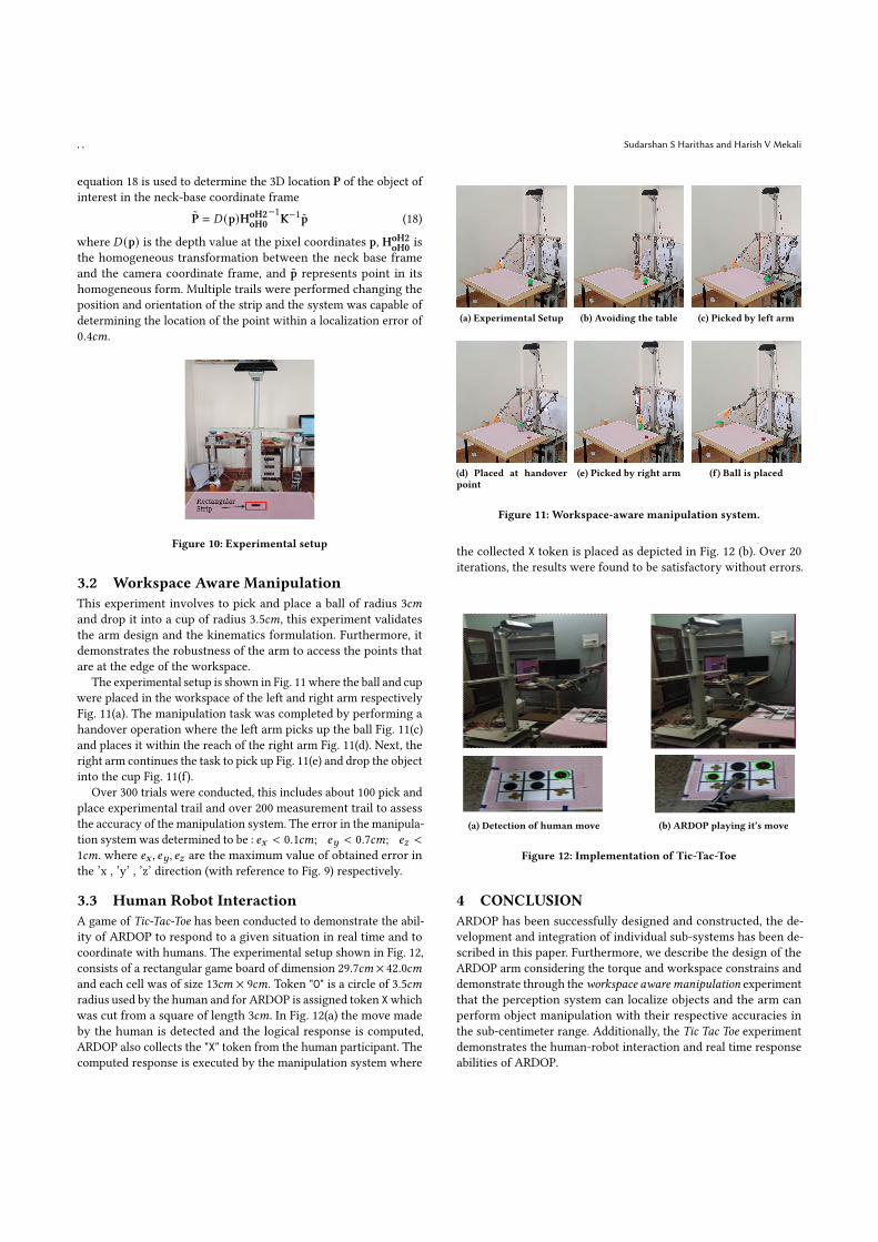
(1) Solution for the Position of the End-Effector:The IK solution for the first three joint angles 𝜃0, 𝜃1, 𝜃2,determine the position of the end-effector. From Fig. 9(a)the ′𝑦′ and ′𝑧′ are obtained as given in Eq. 10 and 11 andfrom Fig. 9(b) ′𝑥 ′ is determined as given in Eq. 9. The equa-tions 9, 10, and 11 describe the position of the arm in spaceas a function of input joint angles.
𝑥 = (𝐿1 sin𝜃1 + (𝐿2 + 𝑙𝑒𝑒 𝑓 ) sin(𝜃1 + 𝜃2)) sin𝜃0 (9)
𝑦 = (𝐿1 sin𝜃1 + (𝐿2 + 𝑙𝑒𝑒 𝑓 ) sin(𝜃1 + 𝜃2)) cos𝜃0 (10)𝑧 = 𝐿1 cos𝜃1 + (𝐿2 + 𝑙𝑒𝑒 𝑓 ) cos(𝜃1 + 𝜃2) + 𝐿0 (11)
𝑋 = 𝑓 (𝜃 ) (12)𝑋 = [𝑥,𝑦, 𝑧] 𝑎𝑛𝑑 𝜃 = [𝜃0, 𝜃1, 𝜃2]
The Jacobianmethod attempts tominimize the error betweenthe current position (𝑋𝑛) and the final position (𝑋𝑑 ) of theend effector. The error is given by
Δ𝑋𝑛 = 𝑋𝑑 − 𝑋𝑛 (13)
An incremental change Δ𝜃𝑛 is made in a direction such thatthe equations converge and the solution is obtained.
Δ𝜃𝑛 = [𝐽 (𝜃 )]−1 .Δ𝑋𝑛 (14)
𝜃𝑛+1 = 𝜃𝑛 + 𝛾Δ𝜃𝑛 (15)Where 𝛾 is the step size parameter which determines therate of convergence and 𝐽 (𝜃 ) is the Jacobian matrix.
(a) Side view (b) Front view
Figure 9: Projection of the arm on vertical and profile plane.
(2) Solution for the Orientation of the End-Effector: Theresults from the previous computation of 𝜃0, 𝜃1, 𝜃2 is usedto obtain the joint angles of the spherical wrist 𝜃3, 𝜃4, 𝜃5 thatdecides orientation of the end-effector. The rotation matrixfrom the arm base frame to the end-effector is expressed as,
𝑅60 = 𝑅10𝑅21𝑅
32𝑅
43𝑅
54𝑅
65 => 𝑅60 = 𝑅30𝑅
63 (16)
From Eq. 16, matrix 𝑅30 can be obtained by substituting for𝜃0, 𝜃1, 𝜃2. The matrix 𝑅63 is the rotation matrix of the 3DOF-spherical wrist and orientation of the end-effector.
𝑅63 = [𝑅30]−1𝑅60 (17)
Eq. 17 is solved to obtain the solution for 𝜃3, 𝜃4, 𝜃5.
3 EXPERIMENTS AND RESULTSExperiments were conducted to evaluate the performance of individ-ual systems and to demonstrate a few tasks the robot can performas a whole. The experiments were object localization, workspaceaware manipulation, motion planning and Tic-Tac-Toe, this sectiondescribes the conduction and results of these tests.
3.1 Object LocalizationYOLOv3 [21] trained on the COCO dataset [22] is used to detectthe objects of interest in space. Object class, bounding box, confi-dence are the outputs of the YOLOv3 model and the centroid of thebounding box is used as the corresponding point of reference forthe object.
This experiment measures the accuracy with which the pointof interest can be localized in space. The experimental setup isshown in Fig. 10, the task was to determine the dimension of therectangular strip given the known pixel co-ordinates of the corners.
The perspective camera projection model [23] [2] was used torecover the 3D location of the corners. The ROS camera calibration3 is used to determine the camera intrinsic matrix K. Using thepixel coordinates p = (𝑢, 𝑣)⊤ and the depth map 𝐷 , the following
3http://wiki.ros.org/openni_launch/Tutorials/IntrinsicCalibration
, , Sudarshan S Harithas and Harish V Mekali
equation 18 is used to determine the 3D location P of the object ofinterest in the neck-base coordinate frame
P̃ = 𝐷 (p)HoH2oH0
−1K−1p̃ (18)
where 𝐷 (p) is the depth value at the pixel coordinates p, HoH2oH0 is
the homogeneous transformation between the neck base frameand the camera coordinate frame, and p̃ represents point in itshomogeneous form. Multiple trails were performed changing theposition and orientation of the strip and the system was capable ofdetermining the location of the point within a localization error of0.4𝑐𝑚.
Figure 10: Experimental setup
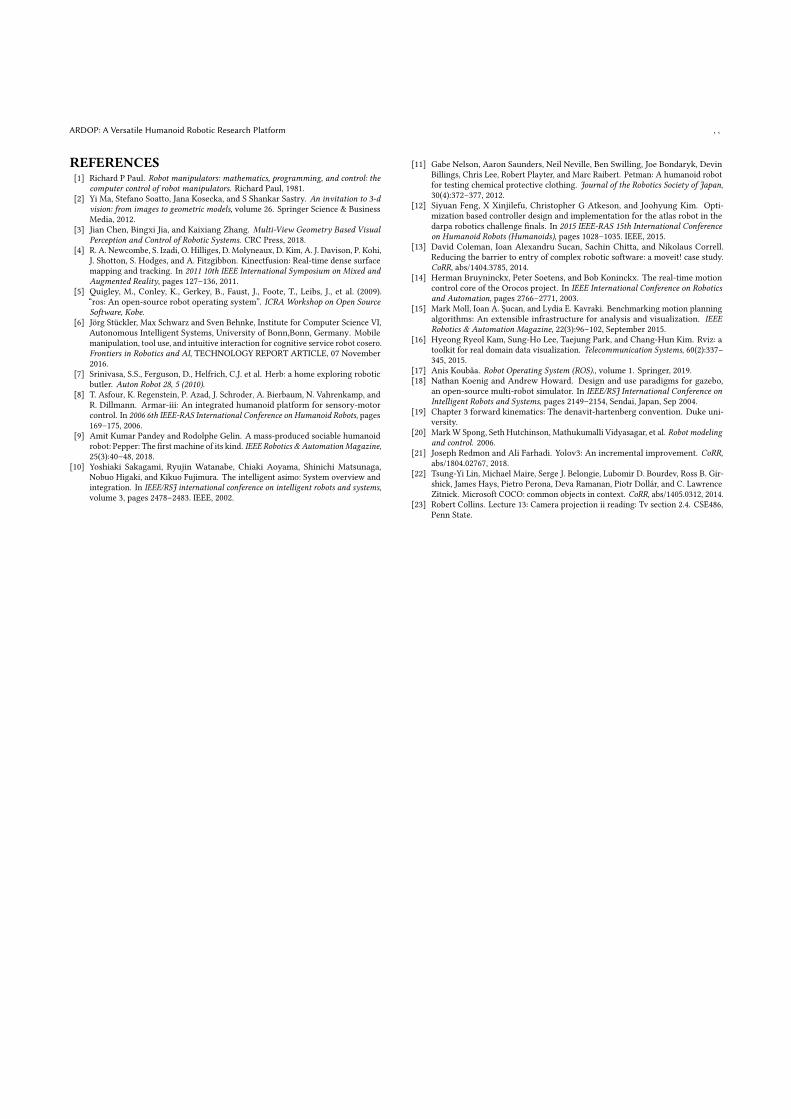
3.2 Workspace Aware ManipulationThis experiment involves to pick and place a ball of radius 3𝑐𝑚and drop it into a cup of radius 3.5𝑐𝑚, this experiment validatesthe arm design and the kinematics formulation. Furthermore, itdemonstrates the robustness of the arm to access the points thatare at the edge of the workspace.
The experimental setup is shown in Fig. 11 where the ball and cupwere placed in the workspace of the left and right arm respectivelyFig. 11(a). The manipulation task was completed by performing ahandover operation where the left arm picks up the ball Fig. 11(c)and places it within the reach of the right arm Fig. 11(d). Next, theright arm continues the task to pick up Fig. 11(e) and drop the objectinto the cup Fig. 11(f).
Over 300 trials were conducted, this includes about 100 pick andplace experimental trail and over 200 measurement trail to assessthe accuracy of the manipulation system. The error in the manipula-tion system was determined to be : 𝑒𝑥 < 0.1𝑐𝑚; 𝑒𝑦 < 0.7𝑐𝑚; 𝑒𝑧 <1𝑐𝑚. where 𝑒𝑥 , 𝑒𝑦, 𝑒𝑧 are the maximum value of obtained error inthe ’x , ’y’ , ’z’ direction (with reference to Fig. 9) respectively.
3.3 Human Robot InteractionA game of Tic-Tac-Toe has been conducted to demonstrate the abil-ity of ARDOP to respond to a given situation in real time and tocoordinate with humans. The experimental setup shown in Fig. 12,consists of a rectangular game board of dimension 29.7𝑐𝑚 × 42.0𝑐𝑚and each cell was of size 13𝑐𝑚 × 9𝑐𝑚. Token "O" is a circle of 3.5𝑐𝑚radius used by the human and for ARDOP is assigned token Xwhichwas cut from a square of length 3𝑐𝑚. In Fig. 12(a) the move madeby the human is detected and the logical response is computed,ARDOP also collects the "X" token from the human participant. Thecomputed response is executed by the manipulation system where
(a) Experimental Setup (b) Avoiding the table (c) Picked by left arm
(d) Placed at handoverpoint
(e) Picked by right arm (f) Ball is placed
Figure 11: Workspace-aware manipulation system.
the collected X token is placed as depicted in Fig. 12 (b). Over 20iterations, the results were found to be satisfactory without errors.
(a) Detection of human move (b) ARDOP playing it’s move
Figure 12: Implementation of Tic-Tac-Toe
4 CONCLUSIONARDOP has been successfully designed and constructed, the de-velopment and integration of individual sub-systems has been de-scribed in this paper. Furthermore, we describe the design of theARDOP arm considering the torque and workspace constrains anddemonstrate through theworkspace aware manipulation experimentthat the perception system can localize objects and the arm canperform object manipulation with their respective accuracies inthe sub-centimeter range. Additionally, the Tic Tac Toe experimentdemonstrates the human-robot interaction and real time responseabilities of ARDOP.
ARDOP: A Versatile Humanoid Robotic Research Platform , ,
REFERENCES[1] Richard P Paul. Robot manipulators: mathematics, programming, and control: the
computer control of robot manipulators. Richard Paul, 1981.[2] Yi Ma, Stefano Soatto, Jana Kosecka, and S Shankar Sastry. An invitation to 3-d
vision: from images to geometric models, volume 26. Springer Science & BusinessMedia, 2012.
[3] Jian Chen, Bingxi Jia, and Kaixiang Zhang. Multi-View Geometry Based VisualPerception and Control of Robotic Systems. CRC Press, 2018.
[4] R. A. Newcombe, S. Izadi, O. Hilliges, D. Molyneaux, D. Kim, A. J. Davison, P. Kohi,J. Shotton, S. Hodges, and A. Fitzgibbon. Kinectfusion: Real-time dense surfacemapping and tracking. In 2011 10th IEEE International Symposium on Mixed andAugmented Reality, pages 127–136, 2011.
[5] Quigley, M., Conley, K., Gerkey, B., Faust, J., Foote, T., Leibs, J., et al. (2009).“ros: An open-source robot operating system”. ICRA Workshop on Open SourceSoftware, Kobe.
[6] Jörg Stückler, Max Schwarz and Sven Behnke, Institute for Computer Science VI,Autonomous Intelligent Systems, University of Bonn,Bonn, Germany. Mobilemanipulation, tool use, and intuitive interaction for cognitive service robot cosero.Frontiers in Robotics and AI, TECHNOLOGY REPORT ARTICLE, 07 November2016.
[7] Srinivasa, S.S., Ferguson, D., Helfrich, C.J. et al. Herb: a home exploring roboticbutler. Auton Robot 28, 5 (2010).
[8] T. Asfour, K. Regenstein, P. Azad, J. Schroder, A. Bierbaum, N. Vahrenkamp, andR. Dillmann. Armar-iii: An integrated humanoid platform for sensory-motorcontrol. In 2006 6th IEEE-RAS International Conference on Humanoid Robots, pages169–175, 2006.
[9] Amit Kumar Pandey and Rodolphe Gelin. A mass-produced sociable humanoidrobot: Pepper: The first machine of its kind. IEEE Robotics & AutomationMagazine,25(3):40–48, 2018.
[10] Yoshiaki Sakagami, Ryujin Watanabe, Chiaki Aoyama, Shinichi Matsunaga,Nobuo Higaki, and Kikuo Fujimura. The intelligent asimo: System overview andintegration. In IEEE/RSJ international conference on intelligent robots and systems,volume 3, pages 2478–2483. IEEE, 2002.
[11] Gabe Nelson, Aaron Saunders, Neil Neville, Ben Swilling, Joe Bondaryk, DevinBillings, Chris Lee, Robert Playter, and Marc Raibert. Petman: A humanoid robotfor testing chemical protective clothing. Journal of the Robotics Society of Japan,30(4):372–377, 2012.
[12] Siyuan Feng, X Xinjilefu, Christopher G Atkeson, and Joohyung Kim. Opti-mization based controller design and implementation for the atlas robot in thedarpa robotics challenge finals. In 2015 IEEE-RAS 15th International Conferenceon Humanoid Robots (Humanoids), pages 1028–1035. IEEE, 2015.
[13] David Coleman, Ioan Alexandru Sucan, Sachin Chitta, and Nikolaus Correll.Reducing the barrier to entry of complex robotic software: a moveit! case study.CoRR, abs/1404.3785, 2014.
[14] Herman Bruyninckx, Peter Soetens, and Bob Koninckx. The real-time motioncontrol core of the Orocos project. In IEEE International Conference on Roboticsand Automation, pages 2766–2771, 2003.
[15] Mark Moll, Ioan A. Şucan, and Lydia E. Kavraki. Benchmarking motion planningalgorithms: An extensible infrastructure for analysis and visualization. IEEERobotics & Automation Magazine, 22(3):96–102, September 2015.
[16] Hyeong Ryeol Kam, Sung-Ho Lee, Taejung Park, and Chang-Hun Kim. Rviz: atoolkit for real domain data visualization. Telecommunication Systems, 60(2):337–345, 2015.
[17] Anis Koubâa. Robot Operating System (ROS)., volume 1. Springer, 2019.[18] Nathan Koenig and Andrew Howard. Design and use paradigms for gazebo,
an open-source multi-robot simulator. In IEEE/RSJ International Conference onIntelligent Robots and Systems, pages 2149–2154, Sendai, Japan, Sep 2004.
[19] Chapter 3 forward kinematics: The denavit-hartenberg convention. Duke uni-versity.
[20] MarkW Spong, Seth Hutchinson, Mathukumalli Vidyasagar, et al. Robot modelingand control. 2006.
[21] Joseph Redmon and Ali Farhadi. Yolov3: An incremental improvement. CoRR,abs/1804.02767, 2018.
[22] Tsung-Yi Lin, Michael Maire, Serge J. Belongie, Lubomir D. Bourdev, Ross B. Gir-shick, James Hays, Pietro Perona, Deva Ramanan, Piotr Dollár, and C. LawrenceZitnick. Microsoft COCO: common objects in context. CoRR, abs/1405.0312, 2014.
[23] Robert Collins. Lecture 13: Camera projection ii reading: Tv section 2.4. CSE486,Penn State.


![Custom Programming for the NAO Robotic Humanoid [6]](https://img.pdfslide.net/doc/110x75/617b19572fd7fe65f90b81f0/custom-programming-for-the-nao-robotic-humanoid-6.jpg)