Embed Size (px)
Citation preview
Abstract—This manuscript deals with V2V/V2I (Vehicle-to-
Vehicle and Vehicle-to-Infrastructure) communication systems
developed for smart city applications, with the aim to provide
new services and tools for making driving safer and improving
the human lifestyle. The considered systems can be supported by
suitable software applications for making the services more
accessible. In this context, research groups and automotive
companies are currently developing systems against children
abandonment in unattended vehicles and are installing them on
new car models. In this paper, an innovative Arduino-based
control system against children abandonment in cars is
described. It introduces new functionalities respect to systems
reported in literature or already on the market, in order to
improve safety and reliability. The proposed system integrates a
mobile app, which gives the possibilities of receiving alert or status
messages, along with images directly acquired from car cockpit.
In addition, the app allows to remotely control several car
functionalities, such as horn activation, windows lowering and
doors locking/unlocking. The wide set of employed sensors
allows to solve some shortcomings of detectability presented by
similar detection systems, thanks to a proper cross-checking of
the acquired information.
Index Terms—smart city, VANET, microcontroller, wireless
communication, safety application, infants health safety.
I. INTRODUCTION
Nowadays, the technology is deeply pervading all human
activities, literally revolutionizing our lifestyles and
allowing to solve or prevent issues irresolvable up few years
ago. Recent advances in electronic and telecommunication
fields allowed t h e development of new communication
standards able to support the interaction between vehicles
(V2V) and between vehicles and infrastructures (V2I).
Manuscript received January 14, 2019; revised March 5, 2019. Date of
publication May 27, 2019. Date of current version June 3, 2019.
Authors are with Dept. of Innovation Engineering, University of Salento,
Lecce, ZIP 73100, ITA.
E-mails: {paolo.visconti, roberto.defazio, donato.cafagna}@unisalento.it,
[email protected], [email protected].
Digital Object Identifier (DOI): 10.24138/jcomss.v15i2.691
These communication standards are enabling the
development of smart city paradigms, featured by new
services and control systems, facing towards the
sustainability, ecological measures and optimized solutions for
mobility and security. Based on these considerations, in 2000
the VANET (vehicular ad-hoc network) concept was
introduced [1]. These new networks are constituted by proper
designed mobile nodes, interacting with fixed infrastructure by
means of complex exchange of data packets. Given the
continuous variability of this scenario, proper designed
communication protocols and routing algorithms were
introduced for ensuring the reliability of new proposed
services. Furthermore, the development of 5G communication
technologies can ensure high throughput and low latency data
transmissions, essential for applications where real-time data
exchange is required.
In the smart city scenario, the VANETs can have potential
applications in several fields of human activities, leading
significant advantages in terms of safety and efficiency of
transport, better usage of parking spaces and enhanced
infotainment services. In particular, the main application field
is related to traffic safety systems, for assisting the drivers in
their drive experience, allowing to prevent road accidents and
to enhance traffic efficiency. Further applications regard
infotainment and wireless payment services, enabling the
driver to perform economic transactions, to access information
and services directly from his vehicle. In most cases, these
services are supported by a properly designed mobile
application, that allows a complete remote control via a
common smartphone or tablet. Therefore, the car companies
are developing, jointly to their innovative services, also
mobile apps for making these services remotely accessible in
user-friendly manner. Hence, applications for monitoring fuel
consumptions and traveled distances, but also to remotely
control the engine starting/stopping, the windows lowering or
to assist the driver during parking place searching are already
present on market, as further described below in this paper.
Arduino-Based Solution for In-Car-
Abandoned Infants' Controlling Remotely
Managed by Smartphone Application
P. Visconti, R. de Fazio, P. Costantini, S. Miccoli, and D. Cafagna
JOURNAL OF COMMUNICATIONS SOFTWARE AND SYSTEMS, VOL. 15, NO. 2, JUNE 2019 89
1845-6421/06/691 © 2019 CCIS
In this context, vehicular sensors networks can be
effectively applied for solving a serious problem, that is
children abandoned inside cars. It is a deplorable problem,
because it involves defenseless individuals that in many cases
are not able to talk. Every year, thousands of this events lead
in some cases to dramatic consequences, as heatstroke or
hypothermia, up to death in extreme situations. In fact, in 2018
the total number of U.S. pediatric vehicular heatstroke deaths
is increased respect to previous year, leading car companies
and research groups to search for not very invasive and
remotely controllable solutions. All the proposed systems,
supported by different sets of sensors, can detect the presence
of child forgotten in the car, by acquiring some meaningful
quantities, such as motion, sound and CO2 concentration. Most
of these systems are installed in car cockpit, integrated inside
its furnishings or into the child seat.
This manuscript describes the development of an innovative
control system based on a Arduino Uno microcontroller board,
for detecting infants forgotten inside a vehicle. The system
allows to enhance its reliability by a proper combination and
cross-checking of acquired information by the wide set of
employed sensors; in this way, it permits to reduce the
probability of false alarms in the detection of infants, under
any conditions in which it could operate. Further novelty of the
developed system is the availability of a software platform,
that allows automatic alerting and remote monitoring
functions, whose functionalities will be described in detail later
in the manuscript . The Arduino Uno acquires information from
a wide set of sensors placed in strategic positions of car cockpit
and combines these data according to the designed firmware
logic for supporting the decision-making process.
Successively, it sends proper warnings for alerting the child
parents and the police of the immediate danger. Specifically,
the system integrates a smart camera equipped with a face
recognition firmware and a sounds recognition board for
detecting the face and the voice of forgotten children.
Moreover, motion sensors (microwave-based and infrared-
based) and a CO2 sensor are placed in proper positions for
detecting eventual human presence inside car. Beside the
proposed hardware and firmware solutions, a suitable IT
platform is designed for supporting the system operation. In
particular, the platform is constituted by a mobile application
and a remote database (DB) interfaced with vehicle’s hardware
section by internet. The platform allows driver to receive alert
messages and images from car cockpit, when a child presence
is detected within a parked car. Furthermore, it allows the
remote control of several car functionalities, as the horn
activation, the windows lowering, the lights flashing, the doors
locking and unlocking.
The remainder of manuscript is structured as follows. The
second paragraph reports an overview about the usage of
V2V/V2I communication on a smart city scenario. The third
paragraph presents an overview on control systems
(manageable by mobile applications) applied to remotely
interfaced vehicles. In the fourth paragraph, at first the
description of developed Arduino-based control system for
detecting infants abandoned in car is reported, successively
mobile app functionalities for supporting the operation of
hardware and firmware sections are reported. Finally, last
section is dedicated to conclusions and future developments.
II. STATE OF ART ABOUT APPLICATIONS OF V2V/V2I
COMMUNICATION IN THE SMART CITIES SCENARIO
The advances in both hardware and software technologies
have provided the opportunity of connecting vehicles with
each other, giving origin to the commonly defined V2V
(vehicle to vehicle) interaction. In this context, the mobile
networking is the main technology for implementing an ad-
hoc network, in which the vehicles represent its nodes.
Furthermore, the interaction between nodes are usually based
on a wireless mobile network, in which all mobile nodes
interact with an access point, constituting the fixed core
network. A vehicular ad-hoc network (VANET) is constituted
by several mobile nodes, dynamically arranged as network,
that exchange information with each other, not supported by a
preexisting static network. For this application, three
communication standards typologies were considered suitable
for vehicular networks, namely the IEEE 802.11p (WAVE)
standard, IEEE 1609 standards family and, finally, the SAE
(Society of Automotive Engineering) J2735 standard. In 2015,
the so-called IEEE Connected Vehicles Initiative was
proposed by IEEE Vehicular Technology Society (VTS),
leading to identify three main areas of interest of VTS, namely
automotive, electronics, mobile radio and transportation
systems; this initiative intends to promote the technical
activities, the networking, the publications, the standards and
the access to technical information in connected vehicles.
Considering a VANET, the routing of data packets between
mobile nodes is a critical issue, because the mobile routers and
their reciprocal connectivity can change frequently. In
addition, also mobile nodes vary continuously their connection
point towards the fixed infrastructure, thus a dynamic routing
protocol is required for efficiently supporting the
communication [1]. Hence, taking into account that the
routing infrastructure is itself mobile, the data packets
forwarding must be dynamic, resulting in a temporary address
assignments to mobile nodes. Consequently, most of routing
algorithms and networking suites must be adapted for an
efficient operating in the mobile scenario.
Furthermore, the introduction of 5G networks will open
new perspectives of applications in smart cities scenario. In
fact, low communication latency, featuring this
communication technology, enables an ensemble of new smart
city applications, including smart urban agriculture, real-time
detection of crime, intelligent traffic management and, of
course, self-driving cars [2].
Several applications, services and technologies regard the
connection of a vehicle to another vehicle or to an
infrastructure or to its surrounding, enabling the vehicle’s
connection to external devices, networks, applications, and
services. In particular, the applications of V2V/V2I
communication are mostly related to improve traffic safety
and efficiency and to provide information or entertainment to
the driver [3], as well as other services, such as parking
assistance, roadside assistance, remote diagnostics and
90 JOURNAL OF COMMUNICATIONS SOFTWARE AND SYSTEMS, VOL. 15, NO. 2, JUNE 2019
telematics for autonomous self-driving vehicles and global
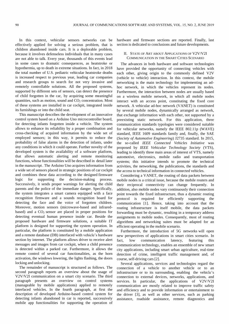
positioning systems (GPS). Regarding to the traffic safety
applications, the following several benefits can be achieved:
Warnings before entering an intersection or a
departing highways;
Warnings about presence of obstacles or accidents on
the road (Fig. 1);
Alerts on a sudden stop condition (e.g., related to
car collisions) or pre-crash warning;
Lane change/keeping warnings/assistance;
Privileging ambulances, fire trucks, and police cars.
All these safety applications are designed to increase the
danger awareness and to reduce the accidents, by means of
Vehicle-to-Vehicle (V2V) or Vehicle-to-Infrastructure (V2I)
communication. For instance, in ref. [4] a warning message
forwarding scheme, designed to improve the message delivery
efficacy in vehicular environments, is proposed. The
developed algorithm broadcasts the emergency warnings using
duplicates as implicit acknowledgements and adopting an
adaptable contention windows size, ensuring a reduced end-to-
end delay. In fact, since the vehicle does not wait for
acknowledgment, the warning message can be forwarded after
only 50ms, allowing a rapid reception. In ref. [5], the authors
propose a prediction scheme, based on a ICU (intelligent
control unit), for estimating the collision probability at
highway intersections, through the use of vehicle-to-vehicle
communication. The ICU constantly monitors and records the
vehicles positions in its range and, as a result of this
information, calculates the collision probability of the vehicle.
Therefore, on the base of future vehicle’s path, the ICU
evaluates the situation dangerously, alerting, by warning
messages, the interested vehicles. Furthermore, ref. [6]
proposes a predictive framework for collision warning based
on connected vehicles, in order to warn the driver if the time-
to- collision is within a preset threshold. The proposed
framework estimates the vehicle trajectory by a Kalman filter
algorithm, for predicting the vehicle collision event. However,
the prediction results demonstrate an efficacy lack of algorithm
in vehicle latitude estimates.
Fig. 1. Hazardous location warning (source: http://car-to-car.org).
The V2V/V2I communication found application, also, in
traffic efficiency optimization, thus improving the efficacy of
the transportation network. This aim is obtained providing
useful information to the transport network managers, as well
as to the vehicle drivers. For instance, this technology can
reduce the traffic congestion through the transmission of
useful information towards a central hub, giving to the
transportation agencies true real-time traffic data, enabling
them to manage their facilities, to maximize efficiency and to
minimize congestions. In ref. [7] a novel architecture for
effectively estimating the traffic density on a specific road is
reported. The developed approach is based on the information
collected by sensor nodes (represented by vehicles and road
side units (RSUs)) and on the road map topology, in order to
precisely estimate the instantaneous density of vehicles.
Specifically, two estimation functions (i.e. V2V and V2I- based
function) are needed for estimating this quantity, because
different typologies of services require different information.
The V2V/V2I systems could also enable vehicles to
cooperate, allowing them to travel much closer each other on
the freeway and platooning. As a result, roads gain more
capacity by fitting more vehicles into the same amount of
space. In addition, systems for supporting the drivers into the
driving experience belong to this scenario, providing them
useful information about the road, related to speed limits,
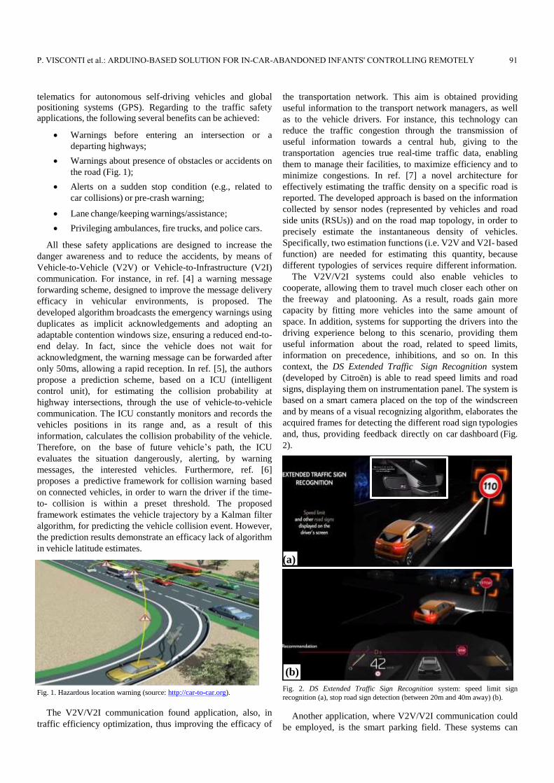
information on precedence, inhibitions, and so on. In this
context, the DS Extended Traffic Sign Recognition system
(developed by Citroën) is able to read speed limits and road
signs, displaying them on instrumentation panel. The system is
based on a smart camera placed on the top of the windscreen
and by means of a visual recognizing algorithm, elaborates the
acquired frames for detecting the different road sign typologies
and, thus, providing feedback directly on car dashboard (Fig.
2).
(a)
(b)
Fig. 2. DS Extended Traffic Sign Recognition system: speed limit sign
recognition (a), stop road sign detection (between 20m and 40m away) (b).
Another application, where V2V/V2I communication could
be employed, is the smart parking field. These systems can
P. VISCONTI et al.: ARDUINO-BASED SOLUTION FOR IN-CAR-ABANDONED INFANTS' CONTROLLING REMOTELY 91
optimize the parking space usage for improving the traffic
flow. In ref. [8], the authors propose a model by which the
users can rapidly find a parking slot, by means of a smart
combination of V2I (vehicle-to-infrastructure) communication
and DGP (distance geometry problem), in order to obtain
accurate and reliable information about the location of most
appropriate parking slot, as function of user needs and
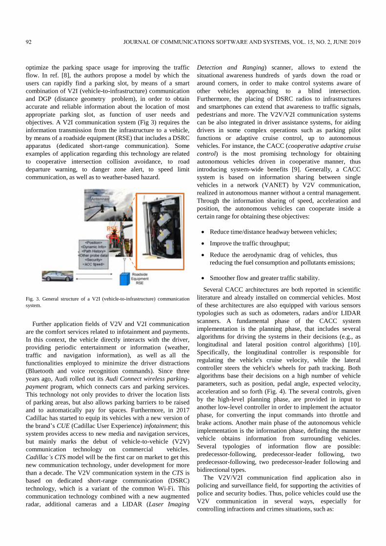
objectives. A V2I communication system (Fig 3) requires the
information transmission from the infrastructure to a vehicle,
by means of a roadside equipment (RSE) that includes a DSRC
apparatus (dedicated short-range communication). Some
examples of application regarding this technology are related
to cooperative intersection collision avoidance, to road
departure warning, to danger zone alert, to speed limit
communication, as well as to weather-based hazard.
Fig. 3. General structure of a V2I (vehicle-to-infrastructure) communication
system.
Further application fields of V2V and V2I communication
are the comfort services related to infotainment and payments.
In this context, the vehicle directly interacts with the driver,
providing periodic entertainment or information (weather,
traffic and navigation information), as well as all the
functionalities employed to minimize the driver distractions
(Bluetooth and voice recognition commands). Since three
years ago, Audi rolled out its Audi Connect wireless parking-
payment program, which connects cars and parking services.
This technology not only provides to driver the location lists
of parking areas, but also allows parking barriers to be raised
and to automatically pay for spaces. Furthermore, in 2017
Cadillac has started to equip its vehicles with a new version of
the brand’s CUE (Cadillac User Experience) infotainment; this
system provides access to new media and navigation services,
but mainly marks the debut of vehicle-to-vehicle (V2V)
communication technology on commercial vehicles.
Cadillac’s CTS model will be the first car on market to get this
new communication technology, under development for more
than a decade. The V2V communication system in the CTS is
based on dedicated short-range communication (DSRC)
technology, which is a variant of the common Wi-Fi. This
communication technology combined with a new augmented
radar, additional cameras and a LIDAR (Laser Imaging
Detection and Ranging) scanner, allows to extend the
situational awareness hundreds of yards down the road or
around corners, in order to make control systems aware of
other vehicles approaching to a blind intersection.
Furthermore, the placing of DSRC radios to infrastructures
and smartphones can extend that awareness to traffic signals,
pedestrians and more. The V2V/V2I communication systems
can be also integrated in driver assistance systems, for aiding
drivers in some complex operations such as parking pilot
functions or adaptive cruise control, up to autonomous
vehicles. For instance, the CACC (cooperative adaptive cruise
control) is the most promising technology for obtaining
autonomous vehicles driven in cooperative manner, thus
introducing system-wide benefits [9]. Generally, a CACC
system is based on information sharing between single
vehicles in a network (VANET) by V2V communication,
realized in autonomous manner without a central management.
Through the information sharing of speed, acceleration and
position, the autonomous vehicles can cooperate inside a
certain range for obtaining these objectives:
Reduce time/distance headway between vehicles;
Improve the traffic throughput;
Reduce the aerodynamic drag of vehicles, thus
reducing the fuel consumption and pollutants emissions;
Smoother flow and greater traffic stability.
Several CACC architectures are both reported in scientific
literature and already installed on commercial vehicles. Most
of these architectures are also equipped with various sensors
typologies such as such as odometers, radars and/or LIDAR
scanners. A fundamental phase of the CACC system
implementation is the planning phase, that includes several
algorithms for driving the systems in their decisions (e.g., as
longitudinal and lateral position control algorithms) [10].
Specifically, the longitudinal controller is responsible for
regulating the vehicle's cruise velocity, while the lateral
controller steers the vehicle's wheels for path tracking. Both
algorithms base their decisions on a high number of vehicle
parameters, such as position, pedal angle, expected velocity,
acceleration and so forth (Fig. 4). The several controls, given
by the high-level planning phase, are provided in input to
another low-level controller in order to implement the actuator
phase, for converting the input commands into throttle and
brake actions. Another main phase of the autonomous vehicle
implementation is the information phase, defining the manner
vehicle obtains information from surrounding vehicles.
Several typologies of information flow are possible:
predecessor-following, predecessor-leader following, two
predecessor-following, two predecessor-leader following and
bidirectional types.
The V2V/V2I communication find application also in
policing and surveillance field, for supporting the activities of
police and security bodies. Thus, police vehicles could use the
V2V communication in several ways, especially for
controlling infractions and crimes situations, such as:
92 JOURNAL OF COMMUNICATIONS SOFTWARE AND SYSTEMS, VOL. 15, NO. 2, JUNE 2019
Surveillance application (e.g. finding stolen vehicles);
Detect any speed excess;
Crossings with red light;
Entry into restricted traffic areas.
Fig. 4. System architecture of CACC (cooperative assisted cruise control)
assisted vehicle.
III. VEHICLE CONTROL SYSTEMS MANAGED BY MOBILE APPS
In last years, technological innovations in electronic, IT and
communication fields have radically changed people’s life and
habits. Just think about how many daily operations are carried
out with the help of complex automated systems to understand
the indissoluble link between modern society and technology.
The progresses in communication, internet and mobile
networks has certainly represented a key moment of
technological development, giving to electronic devices the
ability to interact, to convey information, to remotely
communicate with the user. In particular, the widespread
diffusion of smartphones, able to provide internet connectivity
to everyone in every place and time, has made possible the
design and development of many electronic systems remotely
manageable by the user, through common applications installed
on mobile phones. Today, mobile applications allow to carry
out many operations, from the simplest to the most complex,
from every part of the globe: purchases, mobile banking,
domotics, video surveillance, industrial automation, remote
controlling, environmental monitoring are only some
examples [11].
The modern automation and control systems also find
several applications in automotive field: the latest generation
vehicles are assisted by electronic systems in most of their
operations, managed by control units comparable to computers
for performance and complexity. Scientific research has
focused its attention on the development of electronic systems
able to monitor all vehicle’s functional parameters, to remotely
control specific information and functions [12] or to locate
vehicle from everywhere [13]. Several already marketed
systems can monitor the vehicle’s status, manage specific
functions, check the car’s geographical position, and receive
notifications on particular events and much more.
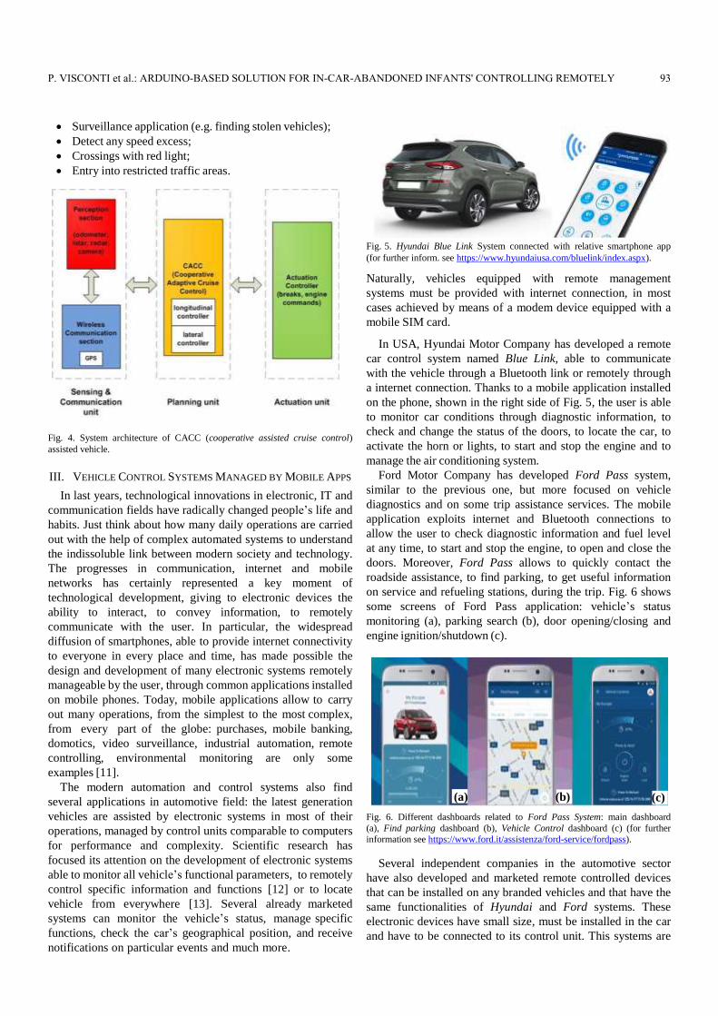
Fig. 5. Hyundai Blue Link System connected with relative smartphone app
(for further inform. see https://www.hyundaiusa.com/bluelink/index.aspx).
Naturally, vehicles equipped with remote management
systems must be provided with internet connection, in most
cases achieved by means of a modem device equipped with a
mobile SIM card.
In USA, Hyundai Motor Company has developed a remote
car control system named Blue Link, able to communicate
with the vehicle through a Bluetooth link or remotely through
a internet connection. Thanks to a mobile application installed
on the phone, shown in the right side of Fig. 5, the user is able
to monitor car conditions through diagnostic information, to
check and change the status of the doors, to locate the car, to
activate the horn or lights, to start and stop the engine and to
manage the air conditioning system.
Ford Motor Company has developed Ford Pass system,
similar to the previous one, but more focused on vehicle
diagnostics and on some trip assistance services. The mobile
application exploits internet and Bluetooth connections to
allow the user to check diagnostic information and fuel level
at any time, to start and stop the engine, to open and close the
doors. Moreover, Ford Pass allows to quickly contact the
roadside assistance, to find parking, to get useful information
on service and refueling stations, during the trip. Fig. 6 shows
some screens of Ford Pass application: vehicle’s status
monitoring (a), parking search (b), door opening/closing and
engine ignition/shutdown (c).
(a) (b) (c)
Fig. 6. Different dashboards related to Ford Pass System: main dashboard
(a), Find parking dashboard (b), Vehicle Control dashboard (c) (for further
information see https://www.ford.it/assistenza/ford-service/fordpass).
Several independent companies in the automotive sector
have also developed and marketed remote controlled devices
that can be installed on any branded vehicles and that have the
same functionalities of Hyundai and Ford systems. These
electronic devices have small size, must be installed in the car
and have to be connected to its control unit. This systems are
P. VISCONTI et al.: ARDUINO-BASED SOLUTION FOR IN-CAR-ABANDONED INFANTS' CONTROLLING REMOTELY 93
provided with a specific Android application, in order to allow
the remote management. Some examples of these universal
aftermarket systems are: V-Auto system (Vodafone, IT),
Smart-Start system (Viper, CA), Smart-Start system (Clifford,
UK) and Mycar system (WarmCarNow, NY). All these
systems employ a small electronic device installed on the
OBD (off-board diagnostics) connector of car control unit,
which has an internal SIM card and is able to communicate
with mobile phones through both bluetooth and remote mobile
connection.
Modern vehicles are becoming adjusted to the current
scenario of "smart cities", featured by increasingly connected
cities, managed by intelligent control systems able to interact
with the real environment and with people, for making everyday
operations much simpler and faster. User safety is certainly
the main target of electronic control systems related to
automotive sector. The systems above described, for example,
beside to car status monitoring and actions managing, allow to
locate the vehicle, to alert the rescuers in case of accident or
illness, to provide assistance in the event of a breakdown or to
prevent a not still happened breakdown.
Other types of electronic systems applied to vehicles have
been dedicated to the solution of specific problems related to
safety, as the fight against theft and damage or the passengers‟
health protection [14]. These systems are often equipped with
different types of sensors, that are able to acquire the greatest
information amount from surrounding environment and to
adopt the appropriate countermeasures in case of dangerous
situations detection.
The anti-theft systems sector is certainly one of the most
successful in terms of market demand. Modern anti-theft
systems, properly connected to vehicle’s control unit, are able
to control many car parameters, to precisely track its position,
to remotely communicate with smartphone applications for
alerting driver in case of suspicious movements, vibrations or
ignition attempts. An example of this kind of system is
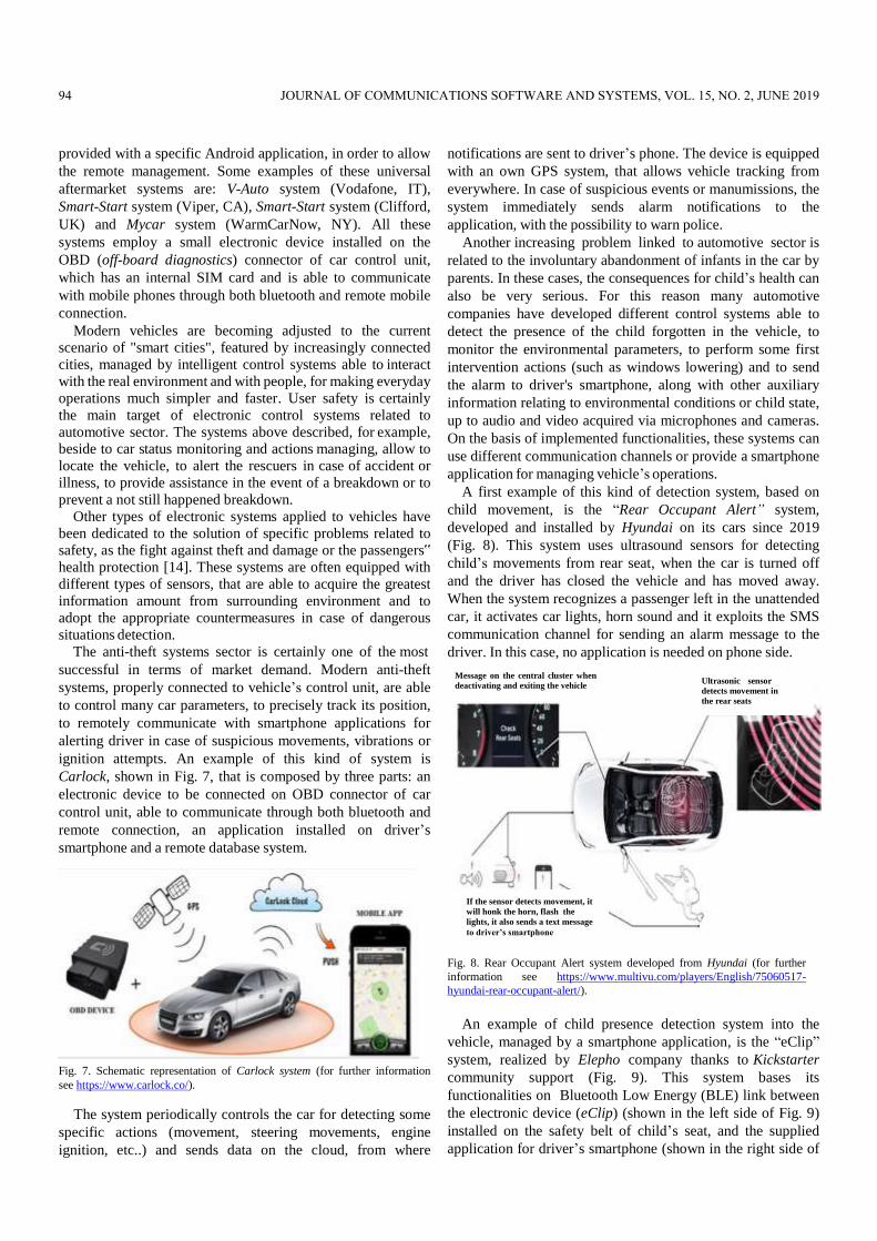
Carlock, shown in Fig. 7, that is composed by three parts: an
electronic device to be connected on OBD connector of car
control unit, able to communicate through both bluetooth and
remote connection, an application installed on driver’s
smartphone and a remote database system.
Fig. 7. Schematic representation of Carlock system (for further information
see https://www.carlock.co/).
The system periodically controls the car for detecting some
specific actions (movement, steering movements, engine
ignition, etc..) and sends data on the cloud, from where
notifications are sent to driver’s phone. The device is equipped
with an own GPS system, that allows vehicle tracking from
everywhere. In case of suspicious events or manumissions, the
system immediately sends alarm notifications to the
application, with the possibility to warn police.
Another increasing problem linked to automotive sector is
related to the involuntary abandonment of infants in the car by
parents. In these cases, the consequences for child’s health can
also be very serious. For this reason many automotive
companies have developed different control systems able to
detect the presence of the child forgotten in the vehicle, to
monitor the environmental parameters, to perform some first
intervention actions (such as windows lowering) and to send
the alarm to driver's smartphone, along with other auxiliary
information relating to environmental conditions or child state,
up to audio and video acquired via microphones and cameras.
On the basis of implemented functionalities, these systems can
use different communication channels or provide a smartphone
application for managing vehicle’s operations.
A first example of this kind of detection system, based on
child movement, is the “Rear Occupant Alert” system,
developed and installed by Hyundai on its cars since 2019
(Fig. 8). This system uses ultrasound sensors for detecting
child’s movements from rear seat, when the car is turned off
and the driver has closed the vehicle and has moved away.
When the system recognizes a passenger left in the unattended
car, it activates car lights, horn sound and it exploits the SMS
communication channel for sending an alarm message to the
driver. In this case, no application is needed on phone side.
Fig. 8. Rear Occupant Alert system developed from Hyundai (for further
information see https://www.multivu.com/players/English/75060517-
hyundai-rear-occupant-alert/).
An example of child presence detection system into the
vehicle, managed by a smartphone application, is the “eClip”
system, realized by Elepho company thanks to Kickstarter
community support (Fig. 9). This system bases its
functionalities on Bluetooth Low Energy (BLE) link between
the electronic device (eClip) (shown in the left side of Fig. 9)
installed on the safety belt of child’s seat, and the supplied
application for driver’s smartphone (shown in the right side of
Ultrasonic sensor
detects movement in
the rear seats
If the sensor detects movement, it
will honk the horn, flash the
lights, it also sends a text message
to driver’s smartphone
Message on the central cluster when
deactivating and exiting the vehicle
94 JOURNAL OF COMMUNICATIONS SOFTWARE AND SYSTEMS, VOL. 15, NO. 2, JUNE 2019
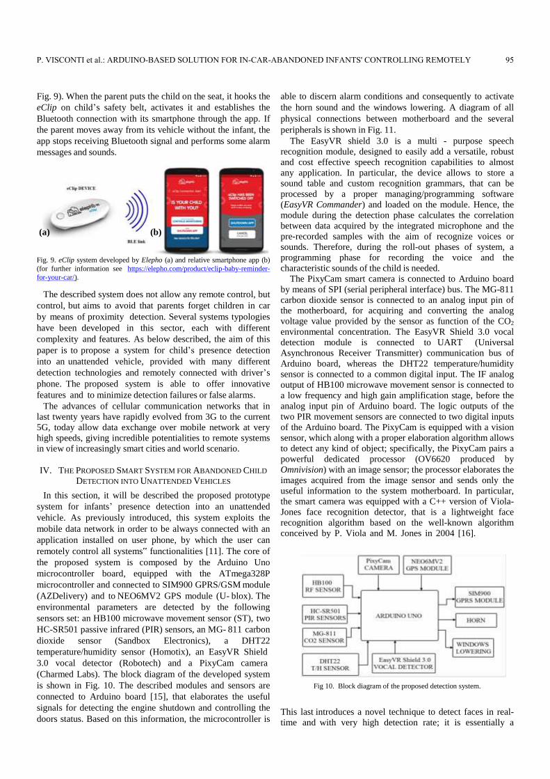
Fig. 9). When the parent puts the child on the seat, it hooks the
eClip on child’s safety belt, activates it and establishes the
Bluetooth connection with its smartphone through the app. If
the parent moves away from its vehicle without the infant, the
app stops receiving Bluetooth signal and performs some alarm
messages and sounds.
(a) (b) Fig. 9. eClip system developed by Elepho (a) and relative smartphone app (b)
(for further information see https://elepho.com/product/eclip-baby-reminder-
for-your-car/).
The described system does not allow any remote control, but
control, but aims to avoid that parents forget children in car
by means of proximity detection. Several systems typologies
have been developed in this sector, each with different
complexity and features. As below described, the aim of this
paper is to propose a system for child’s presence detection
into an unattended vehicle, provided with many different
detection technologies and remotely connected with driver’s
phone. The proposed system is able to offer innovative
features and to minimize detection failures or false alarms.
The advances of cellular communication networks that in
last twenty years have rapidly evolved from 3G to the current
5G, today allow data exchange over mobile network at very
high speeds, giving incredible potentialities to remote systems
in view of increasingly smart cities and world scenario.
IV. THE PROPOSED SMART SYSTEM FOR ABANDONED CHILD
DETECTION INTO UNATTENDED VEHICLES
In this section, it will be described the proposed prototype
system for infants’ presence detection into an unattended
vehicle. As previously introduced, this system exploits the
mobile data network in order to be always connected with an
application installed on user phone, by which the user can
remotely control all systems‟ functionalities [11]. The core of
the proposed system is composed by the Arduino Uno
microcontroller board, equipped with the ATmega328P
microcontroller and connected to SIM900 GPRS/GSM module
(AZDelivery) and to NEO6MV2 GPS module (U- blox). The
environmental parameters are detected by the following
sensors set: an HB100 microwave movement sensor (ST), two
HC-SR501 passive infrared (PIR) sensors, an MG- 811 carbon
dioxide sensor (Sandbox Electronics), a DHT22
temperature/humidity sensor (Homotix), an EasyVR Shield
3.0 vocal detector (Robotech) and a PixyCam camera
(Charmed Labs). The block diagram of the developed system
is shown in Fig. 10. The described modules and sensors are
connected to Arduino board [15], that elaborates the useful
signals for detecting the engine shutdown and controlling the
doors status. Based on this information, the microcontroller is
able to discern alarm conditions and consequently to activate
the horn sound and the windows lowering. A diagram of all
physical connections between motherboard and the several
peripherals is shown in Fig. 11.
The EasyVR shield 3.0 is a multi - purpose speech
recognition module, designed to easily add a versatile, robust
and cost effective speech recognition capabilities to almost
any application. In particular, the device allows to store a
sound table and custom recognition grammars, that can be
processed by a proper managing/programming software
(EasyVR Commander) and loaded on the module. Hence, the
module during the detection phase calculates the correlation
between data acquired by the integrated microphone and the
pre-recorded samples with the aim of recognize voices or
sounds. Therefore, during the roll-out phases of system, a
programming phase for recording the voice and the
characteristic sounds of the child is needed.
The PixyCam smart camera is connected to Arduino board
by means of SPI (serial peripheral interface) bus. The MG-811
carbon dioxide sensor is connected to an analog input pin of
the motherboard, for acquiring and converting the analog
voltage value provided by the sensor as function of the CO2
environmental concentration. The EasyVR Shield 3.0 vocal
detection module is connected to UART (Universal
Asynchronous Receiver Transmitter) communication bus of
Arduino board, whereas the DHT22 temperature/humidity
sensor is connected to a common digital input. The IF analog
output of HB100 microwave movement sensor is connected to
a low frequency and high gain amplification stage, before the
analog input pin of Arduino board. The logic outputs of the
two PIR movement sensors are connected to two digital inputs
of the Arduino board. The PixyCam is equipped with a vision
sensor, which along with a proper elaboration algorithm allows
to detect any kind of object; specifically, the PixyCam pairs a
powerful dedicated processor (OV6620 produced by
Omnivision) with an image sensor; the processor elaborates the
images acquired from the image sensor and sends only the
useful information to the system motherboard. In particular,
the smart camera was equipped with a C++ version of Viola-
Jones face recognition detector, that is a lightweight face
recognition algorithm based on the well-known algorithm
conceived by P. Viola and M. Jones in 2004 [16].
Fig 10. Block diagram of the proposed detection system.
This last introduces a novel technique to detect faces in real-
time and with very high detection rate; it is essentially a
P. VISCONTI et al.: ARDUINO-BASED SOLUTION FOR IN-CAR-ABANDONED INFANTS' CONTROLLING REMOTELY 95
feature-based approach, in which a classifier is trained for
Haar-like rectangular features selected by the Adaboost
algorithm.
(a)
(b)
Fig. 11. Diagram of the physical connections between motherboard and each
block of the proposed system.
The SIM900 GSM/GPRS module and NEO6MV2 GPS
module are connected to the motherboard through UART
interfaces, in order to allow data exchange towards main
microcontroller. Four pins of Arduino Uno unit have been
dedicated to car control unit interfacing, for acquiring
information about vehicle doors and engine status and
managing horn activation and windows lowering.
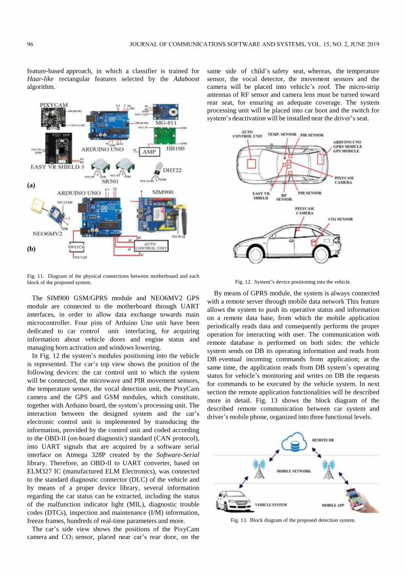
In Fig. 12 the system’s modules positioning into the vehicle
is represented. The car’s top view shows the position of the
following devices: the car control unit to which the system
will be connected, the microwave and PIR movement sensors,
the temperature sensor, the vocal detection unit, the PixyCam
camera and the GPS and GSM modules, which constitute,
together with Arduino board, the system’s processing unit. The
interaction between the designed system and the car’s
electronic control unit is implemented by transducing the
information, provided by the control unit and coded according
to the OBD-II (on-board diagnostic) standard (CAN protocol),
into UART signals that are acquired by a software serial
interface on Atmega 328P created by the Software-Serial
library. Therefore, an OBD-II to UART converter, based on
ELM327 IC (manufactured ELM Electronics), was connected
to the standard diagnostic connector (DLC) of the vehicle and
by means of a proper device library, several information
regarding the car status can be extracted, including the status
of the malfunction indicator light (MIL), diagnostic trouble
codes (DTCs), inspection and maintenance (I/M) information,
freeze frames, hundreds of real-time parameters and more.
The car’s side view shows the positions of the PixyCam
camera and CO2 sensor, placed near car’s rear door, on the
same side of child’s safety seat, whereas, the temperature
sensor, the vocal detector, the movement sensors and the
camera will be placed into vehicle’s roof. The micro-strip
antennas of RF sensor and camera lens must be turned toward
rear seat, for ensuring an adequate coverage. The system
processing unit will be placed into car boot and the switch for
system’s deactivation will be installed near the driver’s seat.
Fig. 12. System‟s device positioning into the vehicle.
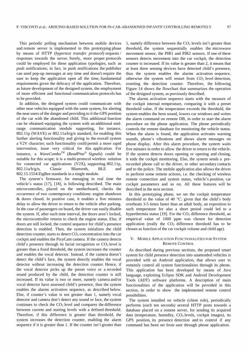
By means of GPRS module, the system is always connected
with a remote server through mobile data network This feature
allows the system to push its operative status and information
on a remote data base, from which the mobile application
periodically reads data and consequently performs the proper
operation for interacting with user. The communication with
remote database is performed on both sides: the vehicle
system sends on DB its operating information and reads from
DB eventual incoming commands from application; at the
same time, the application reads from DB system’s operating
status for vehicle’s monitoring and writes on DB the requests
for commands to be executed by the vehicle system. In next
section the remote application functionalities will be described
more in detail. Fig. 13 shows the block diagram of the
described remote communication between car system and
driver’s mobile phone, organized into three functional levels.
Fig. 13. Block diagram of the proposed detection system.
96 JOURNAL OF COMMUNICATIONS SOFTWARE AND SYSTEMS, VOL. 15, NO. 2, JUNE 2019
This periodic polling mechanism between mobile devices
and remote server is implemented in this prototyping phase
by means of HTTP (hypertext transfer protocol) requests /
responses towards the server. Surely, more proper protocols
could be employed for these application typologies, such as
push notifications; in fact, in push notifications the publisher
can send pop-up messages at any time and doesn't require the
user to keep the application open all the time, fundamental
requirements given the delicacy of the application. Therefore,
as future development of the designed system, the employment
of more efficient and functional communication protocols has
to be provided.
In addition, the designed system could communicate with
other near vehicles equipped with the same system, for alerting
the near users of the danger and providing to it the GPS position
of the car with the abandoned child. This additional function
can be obtained equipping the system with an additional mid-
range communication module supporting, for instance,
802.11p (WAVE) or 802.11a/b/g/n standard, for enabling this
further alerting functionality and giving to the overall system
a V2V character; such functionality could permit a more rapid
intervention, issue very critical for this application. For
instance, a WaveComboTM (ReadPine® Signals) could be
suitable for this scope; it is a multi-protocol wireless solution
for connected car applications (V2X), supporting 802.11p,
802.11a/b/g/n, Classic Bluetooth, BLE and
802.15.1554/ZigBee standards in a single module.
The system’s firmware, for managing in real time the
vehicle’s status [17], [18], is following described. The main
microcontroller, placed on the motherboard, checks the
occurrence of two contemporary conditions: engine shutdown
& doors closed. In positive case, it enables a five minutes
delay to allow the driver to return to the vehicle after parking.
In the case of passengers on board, the driver can easily disable
the system. If, after such time interval, the doors aren’t locked,
the microcontroller returns to check the engine status. Else, if
doors are still locked, the control sequence for child’s presence
detection is enabled. Then, the system initializes the child
detection counter, starts to detect CO2 concentration into the car
cockpit and enables the PixyCam camera. If the camera detects
child’s presence through its facial recognition or CO2 level is
greater than a fixed threshold, the system increases the counter
and enables the vocal detector. Instead, if the camera doesn’t
detect the child’s face, the system directly enables the vocal
detector without increasing the detection counter. Hence, if
the vocal detector picks up the preset voice or a recorded
sound produced by the child, the detection counter is still
increased. If its value is two or more, namely camera and/or
vocal detector have assessed child’s presence, thus the system
enables the alarms activation sequence, as described below.
Else, if counter’s value is not greater than 1, namely vocal
detector and camera don’t detect any sound or face, the system
continues to check the CO2 level and compares the difference
between current and starting levels with a defined threshold.
Therefore, if this difference is greater than threshold, the
system increases the detection counter, enabling the alarm
sequence if it is greater than 1. If the counter isn’t greater than
1, namely difference between the CO2 levels isn’t greater than
threshold, the system sequentially enables the microwave
movement sensor, the PIR1 and PIR2 sensors. If one of these
sensors detects movement into the car cockpit, the detection
counter is increased. If its value is greater than 2, it means that
at least three sensing devices have detected child’s presence,
thus the system enables the alarms activation sequence,
otherwise the system will restart from CO2 level detection,
resetting the detection counter. Therefore, the following
Figure 14 shows the flowchart that summarizes the operation
of the designed system, as previously described.
The alarms activation sequence starts with the measure of
the cockpit internal temperature, comparing it with a preset
threshold value. If the temperature exceeds the threshold, the
system enables the horn sound, lowers car windows and writes
the alarm command on remote DB, in order to start the alarm
procedure on the phone application. The phone periodically
controls the remote database for monitoring the vehicle status.
When the alarm is found, the application activates warning
sounds, phone’s vibrations and shows alarm messages on
phone display. After this alarm procedure, the system waits
five minutes in order to allow the driver to return to the vehicle.
If the system detects doors opening or opening and closing,
it ends the cockpit monitoring. Else, the system sends a pre-
recorded phone call to the driver, to other secondary contacts
and to the police. The mobile application also allows the driver
to perform some remote actions, i.e. the checking of wireless
remote connection and system status, vehicle’s position, car
cockpit parameters and so on. All these features will be
described in the next section.
In this prototyping phase, we set the cockpit temperature
threshold to the value of 40 °C; given that the child’s body
overheats 3-5 times faster than an adult body, an exposition to
such temperature for also a short period could led to a
hyperthermia status [19]. For the CO2 difference threshold, an
empirical value of 1000 ppm was chosen for detection
application (really the CO2 difference threshold has to be
chosen as function of the car cockpit volume and child age).
V. MOBILE APPLICATION FUNCTIONALITIES FOR SYSTEM
REMOTE CONTROL
As described during previous sections, the proposed smart
system for child presence detection into unattended vehicles is
provided with an Android application, that allows user to
remotely control all system functionalities through its phone.
This application has been developed by means of Java
language, exploiting Eclipse SDK and Android Development
Tools (ADT) software platforms. A description of main
functionalities of the application will be provided in this
section, in order to show the implemented remote control
possibilities.
The system installed on vehicle (client role), periodically
performs (each ten seconds) several HTTP posts towards a
database placed on a remote server, for sending its acquired
data (temperature, humidity, CO2 levels, cockpit images), its
GPS position, its presence detection and to control if any
command has been set from user through phone application.
P. VISCONTI et al.: ARDUINO-BASED SOLUTION FOR IN-CAR-ABANDONED INFANTS' CONTROLLING REMOTELY 97
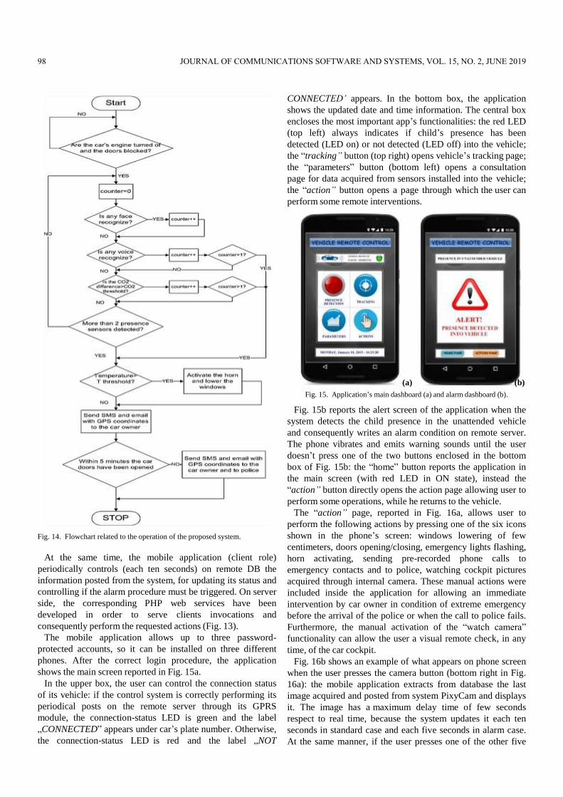
Fig. 14. Flowchart related to the operation of the proposed system.
At the same time, the mobile application (client role)
periodically controls (each ten seconds) on remote DB the
information posted from the system, for updating its status and
controlling if the alarm procedure must be triggered. On server
side, the corresponding PHP web services have been
developed in order to serve clients invocations and
consequently perform the requested actions (Fig. 13).
The mobile application allows up to three password-
protected accounts, so it can be installed on three different
phones. After the correct login procedure, the application
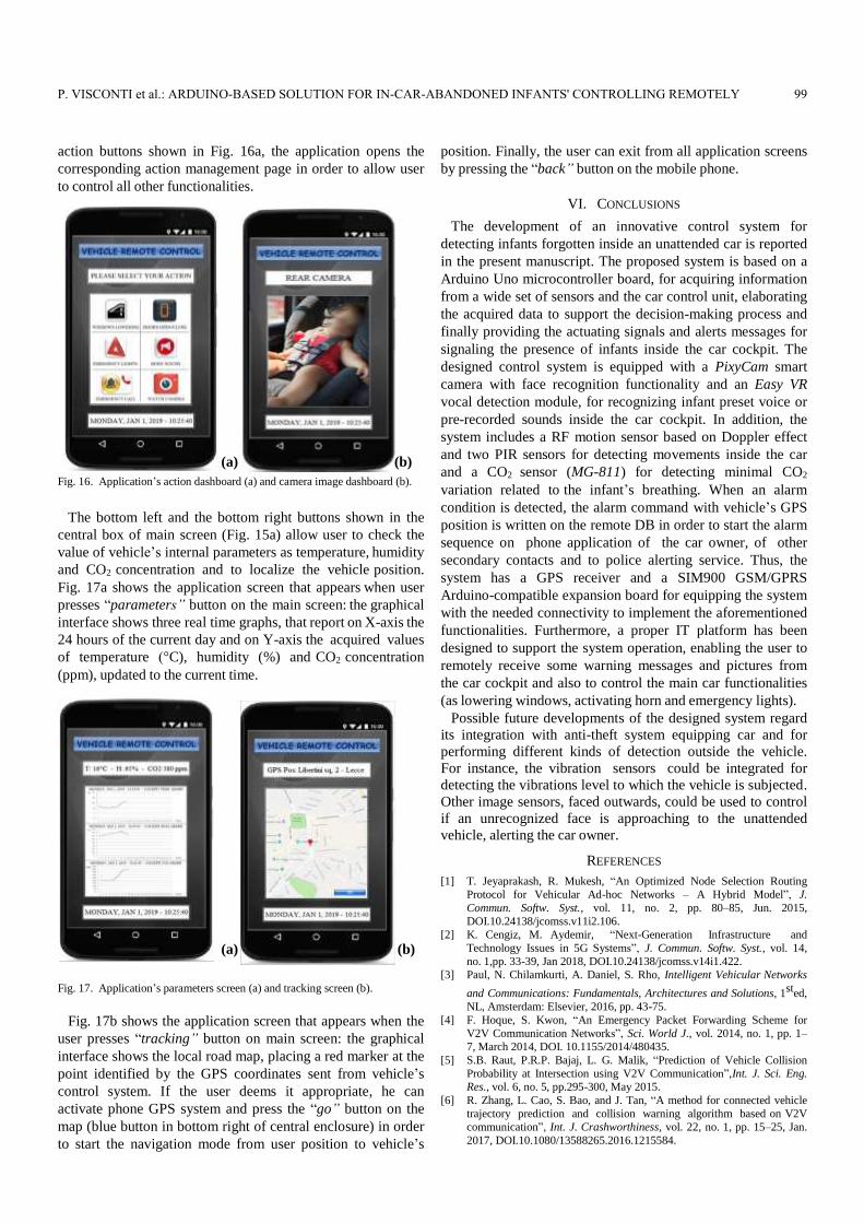
shows the main screen reported in Fig. 15a.
In the upper box, the user can control the connection status
of its vehicle: if the control system is correctly performing its
periodical posts on the remote server through its GPRS
module, the connection-status LED is green and the label
„CONNECTED‟ appears under car’s plate number. Otherwise,
the connection-status LED is red and the label „NOT
CONNECTED’ appears. In the bottom box, the application
shows the updated date and time information. The central box
encloses the most important app’s functionalities: the red LED
(top left) always indicates if child’s presence has been
detected (LED on) or not detected (LED off) into the vehicle;
the “tracking” button (top right) opens vehicle’s tracking page;
the “parameters” button (bottom left) opens a consultation
page for data acquired from sensors installed into the vehicle;
the “action” button opens a page through which the user can
perform some remote interventions.
(a) (b)
Fig. 15. Application’s main dashboard (a) and alarm dashboard (b).
Fig. 15b reports the alert screen of the application when the
system detects the child presence in the unattended vehicle
and consequently writes an alarm condition on remote server.
The phone vibrates and emits warning sounds until the user
doesn’t press one of the two buttons enclosed in the bottom
box of Fig. 15b: the “home” button reports the application in
the main screen (with red LED in ON state), instead the
“action” button directly opens the action page allowing user to
perform some operations, while he returns to the vehicle.
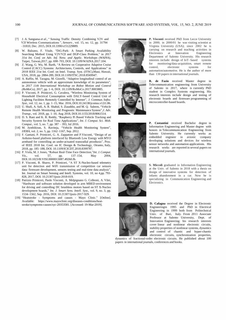
The “action” page, reported in Fig. 16a, allows user to
perform the following actions by pressing one of the six icons
shown in the phone’s screen: windows lowering of few
centimeters, doors opening/closing, emergency lights flashing,
horn activating, sending pre-recorded phone calls to
emergency contacts and to police, watching cockpit pictures
acquired through internal camera. These manual actions were
included inside the application for allowing an immediate
intervention by car owner in condition of extreme emergency
before the arrival of the police or when the call to police fails.
Furthermore, the manual activation of the “watch camera”
functionality can allow the user a visual remote check, in any
time, of the car cockpit.
Fig. 16b shows an example of what appears on phone screen
when the user presses the camera button (bottom right in Fig.
16a): the mobile application extracts from database the last
image acquired and posted from system PixyCam and displays
it. The image has a maximum delay time of few seconds
respect to real time, because the system updates it each ten
seconds in standard case and each five seconds in alarm case.
At the same manner, if the user presses one of the other five
98 JOURNAL OF COMMUNICATIONS SOFTWARE AND SYSTEMS, VOL. 15, NO. 2, JUNE 2019
action buttons shown in Fig. 16a, the application opens the
corresponding action management page in order to allow user
to control all other functionalities.
(a) (b)
Fig. 16. Application’s action dashboard (a) and camera image dashboard (b).
The bottom left and the bottom right buttons shown in the
central box of main screen (Fig. 15a) allow user to check the
value of vehicle’s internal parameters as temperature, humidity
and CO2 concentration and to localize the vehicle position.
Fig. 17a shows the application screen that appears when user
presses “parameters” button on the main screen: the graphical
interface shows three real time graphs, that report on X-axis the
24 hours of the current day and on Y-axis the acquired values
of temperature (°C), humidity (%) and CO2 concentration
(ppm), updated to the current time.
(a) (b)
Fig. 17. Application’s parameters screen (a) and tracking screen (b).
Fig. 17b shows the application screen that appears when the
user presses “tracking” button on main screen: the graphical
interface shows the local road map, placing a red marker at the
point identified by the GPS coordinates sent from vehicle’s
control system. If the user deems it appropriate, he can
activate phone GPS system and press the “go” button on the
map (blue button in bottom right of central enclosure) in order
to start the navigation mode from user position to vehicle’s
position. Finally, the user can exit from all application screens
by pressing the “back” button on the mobile phone.
VI. CONCLUSIONS
The development of an innovative control system for
detecting infants forgotten inside an unattended car is reported
in the present manuscript. The proposed system is based on a
Arduino Uno microcontroller board, for acquiring information
from a wide set of sensors and the car control unit, elaborating
the acquired data to support the decision-making process and
finally providing the actuating signals and alerts messages for
signaling the presence of infants inside the car cockpit. The
designed control system is equipped with a PixyCam smart
camera with face recognition functionality and an Easy VR
vocal detection module, for recognizing infant preset voice or
pre-recorded sounds inside the car cockpit. In addition, the
system includes a RF motion sensor based on Doppler effect
and two PIR sensors for detecting movements inside the car
and a CO2 sensor (MG-811) for detecting minimal CO2
variation related to the infant’s breathing. When an alarm
condition is detected, the alarm command with vehicle’s GPS
position is written on the remote DB in order to start the alarm
sequence on phone application of the car owner, of other
secondary contacts and to police alerting service. Thus, the
system has a GPS receiver and a SIM900 GSM/GPRS
Arduino-compatible expansion board for equipping the system
with the needed connectivity to implement the aforementioned
functionalities. Furthermore, a proper IT platform has been
designed to support the system operation, enabling the user to
remotely receive some warning messages and pictures from
the car cockpit and also to control the main car functionalities
(as lowering windows, activating horn and emergency lights).
Possible future developments of the designed system regard
its integration with anti-theft system equipping car and for
performing different kinds of detection outside the vehicle.
For instance, the vibration sensors could be integrated for
detecting the vibrations level to which the vehicle is subjected.
Other image sensors, faced outwards, could be used to control
if an unrecognized face is approaching to the unattended
vehicle, alerting the car owner.
REFERENCES
[1] T. Jeyaprakash, R. Mukesh, “An Optimized Node Selection Routing
Protocol for Vehicular Ad-hoc Networks – A Hybrid Model”, J.
Commun. Softw. Syst., vol. 11, no. 2, pp. 80–85, Jun. 2015,
DOI.10.24138/jcomss.v11i2.106.
[2] K. Cengiz, M. Aydemir, “Next-Generation Infrastructure and
Technology Issues in 5G Systems”, J. Commun. Softw. Syst., vol. 14,
no. 1,pp. 33-39, Jan 2018, DOI.10.24138/jcomss.v14i1.422.
[3] Paul, N. Chilamkurti, A. Daniel, S. Rho, Intelligent Vehicular Networks
and Communications: Fundamentals, Architectures and Solutions, 1sted,
NL, Amsterdam: Elsevier, 2016, pp. 43-75.
[4] F. Hoque, S. Kwon, “An Emergency Packet Forwarding Scheme for
V2V Communication Networks”, Sci. World J., vol. 2014, no. 1, pp. 1–
7, March 2014, DOI. 10.1155/2014/480435.
[5] S.B. Raut, P.R.P. Bajaj, L. G. Malik, “Prediction of Vehicle Collision
Probability at Intersection using V2V Communication”,Int. J. Sci. Eng.
Res., vol. 6, no. 5, pp.295-300, May 2015.
[6] R. Zhang, L. Cao, S. Bao, and J. Tan, “A method for connected vehicle
trajectory prediction and collision warning algorithm based on V2V
communication”, Int. J. Crashworthiness, vol. 22, no. 1, pp. 15–25, Jan.
2017, DOI.10.1080/13588265.2016.1215584.
P. VISCONTI et al.: ARDUINO-BASED SOLUTION FOR IN-CAR-ABANDONED INFANTS' CONTROLLING REMOTELY 99
[7] J. A. Sanguesa et al., “ Sensing Traffic Density Combining V2V and
V2I Wireless Communications ”, Sensors , vol. 15, no. 12, pp. 31794
–31810, Dec. 2015, DOI.10.3390/s151229889.
[8] W. Balzano, F. Vitale, “DiG-Park: A Smart Parking Availability
Searching Method Using V2V/V2I and DGP-Class Problem,” in 2017
31st Int. Conf. on Adv. Inf. Netw. and Applic. Workshops (WAINA),
Taipei, Taiwan,2017, pp. 698–703, DOI. 10.1109/WAINA.2017.104.
[9] Z. Wang, G. Wu, M. Barth, “A Review on Cooperative Adaptive Cruise
Control (CACC) Systems: Architectures, Controls, and Applications” in
2018 IEEE 21st Int. Conf. on Intel. Transp. Syst. (ITSC),Maui, Hawaii,
USA, 2018, pp. 2884-289, DOI.10.1109/ITSC.2018.8569947.
[10] A. Raffin, M. Taragna, M. Giorelli, “Adaptive longitudinal control of an
autonomous vehicle with an approximate knowledge of its parameters”,
in 2017 11th International Workshop on Robot Motion and Control
(RoMoCo), 2017, pp. 1–6, DOI. 10.1109/RoMoCo.2017.8003885.
[11] P. Visconti, P. Primiceri, G. Cavalera, “Wireless Monitoring System of
Household Electrical Consumption with DALY-based Control Unit of
Lighting Facilities Remotely Controlled by Internet”, J. Commun. Softw.
Syst., vol. 12, no. 1, pp. 1–15, Mar. 2016, DOI.10.24138/jcomss.v12i1.86.
[12] U. Shafi, A. Safi, A. R. Shahid, S. Ziauddin, and M. Q. Saleem, “Vehicle
Remote Health Monitoring and Prognostic Maintenance System”,J. Adv.
Transp., vol. 2018, pp. 1–10, Aug 2018, DOI.10.1155/2018/8061514.
[13] D. S. Rani and K. R. Reddy, “Raspberry Pi Based Vehicle Tracking and
Security System for Real Time Applications”, Int. J. Comput. Sci. Mob.
Comput., vol. 5, no. 7, pp. 387 – 393, Jul 2016.
[14] M. Jyothikiran, S. Raviteja, “Vehicle Health Monitoring System”,
IJERA, vol. 2, no. 5, pp. 1162–1167, Sep. 2012.
[15] F. Gaetani, P. Primiceri, G. A. Zappatore and P.Visconti, “Design of an
Arduino-based platform interfaced by Bluetooth Low Energy with MYO
armband for controlling an under-actuated transradial prosthesis”, Proc.
of IEEE 2018 Int. Conf. on IC Design & Technology, Otranto, Italy,
2018, pp. 185–188, DOI. 10.1109/ICICDT.2018.8399787.
[16] P. Viola, M. J. Jones, “Robust Real-Time Face Detection,”Int. J. Comput.
Vis., vol. 57, pp. 137–154, May 2004,
DOI.10.1023/B:VISI.0000013087.49260.fb.
[17] P. Visconti, B. Sbarro, P. Primiceri, “A ST X-Nucleo-based telemetry
unit for detection and WiFi transmission of competition car sensors
data: firmware development, sensors testing and real-time data analysis”,
Int. Journal on Smart Sensing and Intell. Systems, vol. 10, no 4,pp. 793-
828, 2017, DOI. 10.21307/ijssis-2018-019.
[18] Patrizio Primiceri, Paolo Visconti, A. Melpignano G. Colleoni, A. Vilei,
“Hardware and software solution developed in arm MBED environment
for driving and controlling DC brushless motors based on ST X-Nucleo
development boards,” Int. J. Smart Sens. Intell. Syst., vol. 9, no. 3, pp.
1534–1562, Sep. 2016, DOI: 10.21307/ijssis-2017-929.
[19] “Heatstroke - Symptoms and causes - Mayo Clinic.” [Online].
Available: https://www.mayoclinic.org/diseases-conditions/heat-
stroke/symptoms-causes/syc-20353581. [Accessed: 19-Mar-2019].
P. Visconti received PhD from Lecce University
in 2000; in 2000/01 he was visiting scientist at
Virginia University (USA); since 2002 he is
carrying on research and teaching activities in
Electronics at Innovation Engineering
Department of Salento University. His research
interests include: design of IoT- based systems
for monitoring/data-acquisition, smart remote
control, electronic systems for
automation/automotive. He is the author of more
than 130 papers in international journals.
R. de Fazio received Master degree in
Telecommunication engineering from University
of Salento in 2017, where is currently PhD
student in Complex Systems engineering. His
research interests include design and testing of
electronic boards and firmware programming of
microcontroller-based boards.
P. Costantini received Bachelor degree in
Information Engineering and Master degree with
honors in Telecommunication Engineering from
Salento University. He currently works as
embedded engineer in avionic company
developing solutions and devices for wireless
sensor networks and automation applications. His
research works are reported in several papers on
international journals.
S. Miccoli graduated in Information Engineering
at the Univ. of Salento in 2018 with a thesis on
design of innovative systems for detection of
infants abandonment in a car. Now he is
specializing in Communication Engineering and
Electronics.
D. Cafagna received the Degree in Electronic
Engineeringin 1995 and PhD in Electrical
Engineering in 1999 both from Politechnical
Univ. of Bari, Italy. From 2011 Associate
Professor at Salento University, Dept. of
Innovation Engineering; his research interests
cover linear and nonlinear electronic circuits,
stability properties of nonlinear systems, dynamics
and control of chaotic and hyper-chaotic
electronic circuits, synchronization properties,
dynamics of fractional-order electronic circuits. He published about 100
papers in international journals, conferences and books.
100 JOURNAL OF COMMUNICATIONS SOFTWARE AND SYSTEMS, VOL. 15, NO. 2, JUNE 2019