Embed Size (px)
DESCRIPTION
Arduino MIDI Synth Paul Halpin2011
Citation preview

Arduino MIDI Synthesizer Paul Halpin BSc – Music, Multimedia and Electronics ELEC2645 Embedded Systems Project
School of Electronic and Electrical Engineering FACULTY OF ENGINEERING
Session 2010 / 2011 Student ID 200481604

Contents
1. Abstract 2
2. Introduction 2
3. Software Overview 2
4. Hardware Overview 4
5. Testing 5
6. Conclusion 6
7. References 7
1

1. Abstract
The basis of this module was the design and crea5on of a microcontroller-‐based embedded system -‐ in my case a MIDI-‐controlled synthesiser. This is a complete self-‐contained product that can interpret an incoming MIDI signal from a 5-‐pin DIN connec5on and translate it into a pitched square-‐oscillator. The sound output is then either sent through an in-‐built speaker or sent to a 3.5mm audio outlet that can be plugged into many devices (mixer, headphones). The output can be selected by the user by a toggle switch. The user can further manipulate the sound by defining a note length using the knob on the top of the enclosure. This report outlines the different stages involved in the comple5on of this project.
2. Introduc1on
The Arduino is a popular device for prototyping projects that integrate hardware and soKware by programming a microcontroller. The device is accompanied by a piece of simple desktop soKware that allows the user to create programs for the microcontroller in an easy program language called “Wiring”, a modified version of C/C++ that makes designing input/output applica5ons much easier.[1] This method of designing embedded systems can bring together many different areas of electronics without having to create new interfaces between them. The Arduino microcontrollers can operate a variety of components from servos to LCD displays -‐ most commonly using logic func5ons in and out of the microcontroller pins or a stream of serial data from a single pin. The fact that I am enrolled as an M.M.E student was major factor in the process of deciding what my project was going to be. I thought it would be interes5ng to research different musical opportuni5es available using the Arduino. There are many websites where people share and discuss ideas rela5ng to Arduino projects, and a large selec5on of these are musically related. In the wiring library for the Arduino.
3. So4ware Overview
The most basic form of musicality is available in the form of the tone() func5on; this is a modified version of wiring’s pulse-‐width modula5on library, where instead of being able to adjust the duty cycle, the user can change the frequency and length values of a note at a par5cular output pin. This is the main func5on that my project u5lises. The soKware sec5on of the code relies on a small sec5on of the Arduino MIDI library.[2] This library makes it easy to set the baud rate to 31250 (MIDI-‐compliant), interpret and generate MIDI serial data. The only MIDI data I am concerned with in my project is note data. This comes as two bytes in the serial. Firstly, my program analyses all incoming MIDI messages and filters out “NoteOn’ messages. When a “NoteOn” message is received, the “sound()” func5on is called. If the second byte (MIDI.getData2 -‐ this contains the velocity and dura5on informa5on) is not greater than 0, the func5on will end. Since the tone() output only has one velocity, I don’t use the data from the second byte. Instead I have a poten5ometer to adjust the dura5on of the notes. The program then analyses the first byte (MIDI.getData1) to get the pitch of the note (between 0-‐127). The corresponding frequency is then determined from my array declared at the start of the code (int MIDI[128]). This frequency, combined with the current mapped value of the poten5ometer is applied to a tone() func5on with two variables and the note indicator LED is ac5vated. Here is an overview of the program:
2

Start/Stop
Declare Global Variables
(int MIDI[128];)
setup() Func?on
loop()Func?on
Declare Local Variables
If MIDI.getData2 > 0
Digital Pin 2 = HIGH
Digital Pin 8 = noTone
YES
MIDI.read
MIDI.getType
If type = NoteOn
Digital Pin 2 = LOW
NO
Set Outputs, Inputs
sound()Func?on
YES
loop()Func?on
sound()Func?on
int n = MIDI.getData1
int pitch = midi[n]
analogRead Pin 0= sustain
sustain =map(sustain,
0,1023,30,1000)
tonepin 8
frequency = pitchdelay = sustain
Stop
Start
(Note LED)
(Note LED)
(Speaker Pin)
(Convert MIDI number to frequency)
(Poten?ometer input)
(Suitable Values for delay)
(Main sound output)
NO
Checks to see if there isincoming note data
3

Before deciding on using an array to store the frequency values, I experimented with an algorithm that converted the MIDI number into the actual frequency:
frequency = 440 * 2^((n-‐69)/12)(Where “n” is the MIDI number)
This gave a frequency accurate to as many decimal places as you need but I ran into errors when tes5ng it out on the hardware. I believe that it is because of physical limita5ons in the microcontroller, that it can’t calculate indices of that scale on the fly.
4. Hardware Overview
Most of the components in my project are housed in the enclosure, away from the board.
OUTSOURCED COMPONENTS
-On switch-Output toggle-MIDI connector-Audio jack-Speaker-Potentiometer-Red LED-Blue LED-Battery Clip / 9V Battery
CIRCUIT BOARD COMPONENTS
-Voltage regulator (9V -> 5V)-16MHz crystal oscillator-ATMega328P chip-Op amp-Resistors / Capacitors
19 connections
This sec5on of the schema5c outlines the power regula5on in the circuit. The IC in the centre converts a 9V bafery’s voltage to 5V -‐ a safe opera5ng level for the ATMega328.
4
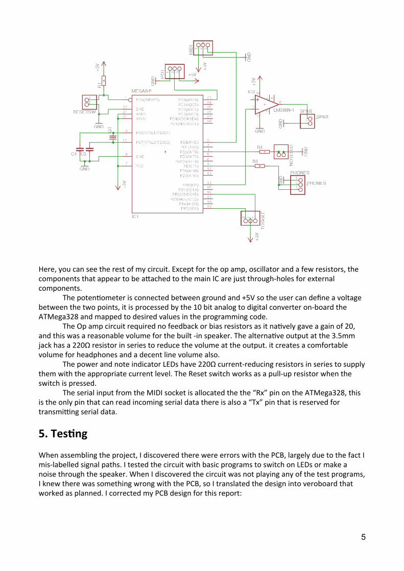
Here, you can see the rest of my circuit. Except for the op amp, oscillator and a few resistors, the components that appear to be afached to the main IC are just through-‐holes for external components. The poten5ometer is connected between ground and +5V so the user can define a voltage between the two points, it is processed by the 10 bit analog to digital converter on-‐board the ATMega328 and mapped to desired values in the programming code. The Op amp circuit required no feedback or bias resistors as it na5vely gave a gain of 20, and this was a reasonable volume for the built -‐in speaker. The alterna5ve output at the 3.5mm jack has a 220Ω resistor in series to reduce the volume at the output. it creates a comfortable volume for headphones and a decent line volume also. The power and note indicator LEDs have 220Ω current-‐reducing resistors in series to supply them with the appropriate current level. The Reset switch works as a pull-‐up resistor when the switch is pressed. The serial input from the MIDI socket is allocated the the “Rx” pin on the ATMega328, this is the only pin that can read incoming serial data there is also a “Tx” pin that is reserved for transmiing serial data.
5. Tes1ng
When assembling the project, I discovered there were errors with the PCB, largely due to the fact I mis-‐labelled signal paths. I tested the circuit with basic programs to switch on LEDs or make a noise through the speaker. When I discovered the circuit was not playing any of the test programs, I knew there was something wrong with the PCB, so I translated the design into veroboard that worked as planned. I corrected my PCB design for this report:
5
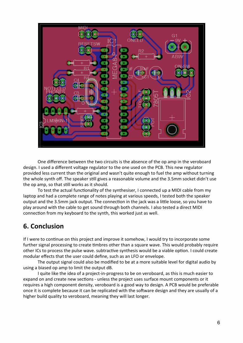
One difference between the two circuits is the absence of the op amp in the veroboard design. I used a different voltage regulator to the one used on the PCB. This new regulator provided less current than the original and wasn’t quite enough to fuel the amp without turning the whole synth off. The speaker s5ll gives a reasonable volume and the 3.5mm socket didn’t use the op amp, so that s5ll works as it should. To test the actual func5onality of the synthesiser, I connected up a MIDI cable from my laptop and had a complete range of notes playing at various speeds, I tested both the speaker output and the 3.5mm jack output. The connec5on in the jack was a lifle loose, so you have to play around with the cable to get sound through both channels. I also tested a direct MIDI connec5on from my keyboard to the synth, this worked just as well.
6. Conclusion
If I were to con5nue on this project and improve it somehow, I would try to incorporate some further signal processing to create 5mbres other than a square wave. This would probably require other ICs to process the pulse wave. subtrac5ve synthesis would be a viable op5on. I could create modular effects that the user could define, such as an LFO or envelope. The output signal could also be modified to be at a more suitable level for digital audio by using a biased op amp to limit the output dB. I quite like the idea of a project-‐in-‐progress to be on veroboard, as this is much easier to expand on and create new sec5ons -‐ unless the project uses surface mount components or it requires a high component density, veroboard is a good way to design. A PCB would be preferable once it is complete because it can be replicated with the soKware design and they are usually of a higher build quality to veroboard, meaning they will last longer.
6

References
[1] "Wiring Language (API)". 17 May 2011. < h/p://wiring.org.co/reference/ >.
[2] "Arduino MIDI Library". 17 May 2011. <h/p://sourceforge.net/projects/arduinomidilib/ >.
7