Embed Size (px)
Citation preview
Arduino Projects from theorycircuit.com
July 2016 – top 5
1. RTC DS-1307 with Arduino
Every real time applications need one RTC chip. In this tutorial you can get idea and knowledge about RTC DS 1307 (Real Time Clock chip) and interfacing with Arduino
development board.
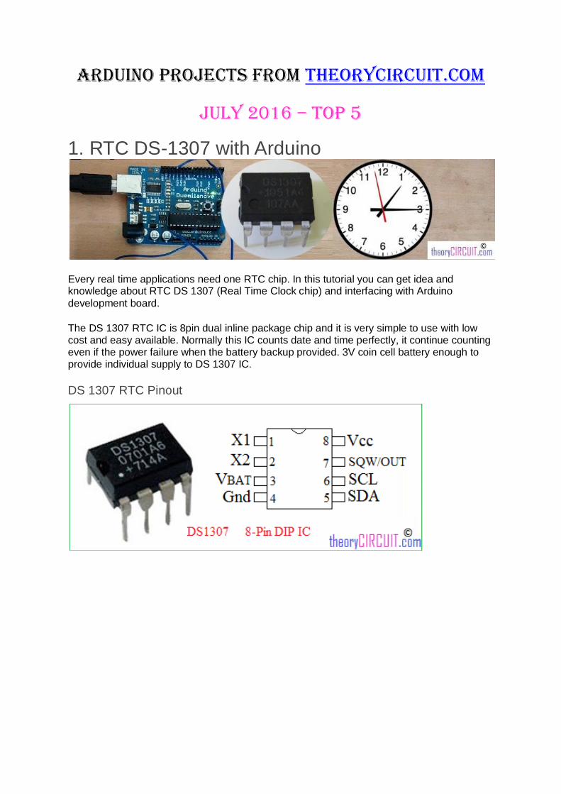
The DS 1307 RTC IC is 8pin dual inline package chip and it is very simple to use with low cost and easy available. Normally this IC counts date and time perfectly, it continue counting even if the power failure when the battery backup provided. 3V coin cell battery enough to provide individual supply to DS 1307 IC.
DS 1307 RTC Pinout

Block Diagram of DS1307
This RTC IC contains more than seven internal blocks, the first one is oscillator and divider it is connected with standard 32.768 KHz quartz crystal, the internal oscillator circuitry is designed for operation with a crystal having a specified capacitance of 12.5 pF. The power control block have Vcc, Gnd and Vbat pins, here Vcc and Gnd pins provides primary power
supply.
When the voltage is applied within normal limits, the device is fully accessible and data can be written and read. When the battery supply connected (Vbat) without primary supply read and writes are inhibited, but the time keeping function continues.
The DS 1307 RTC communicates with external world through serial bus interface I²C
protocol. SCL (Serial Clock), SDA (Serial Data).
RTC module
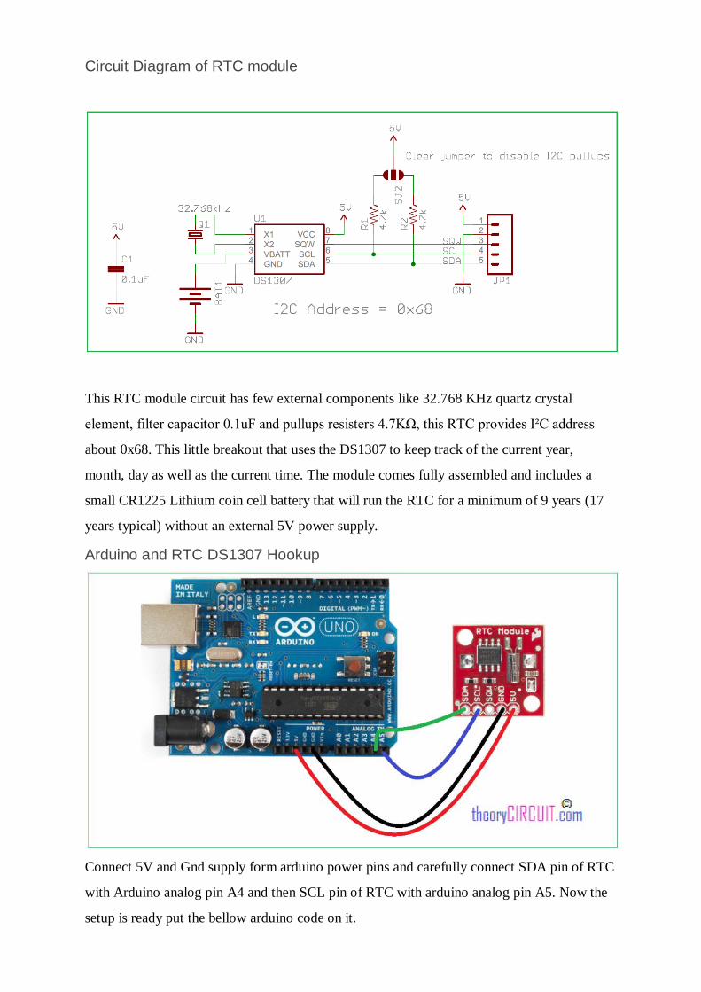
Circuit Diagram of RTC module
This RTC module circuit has few external components like 32.768 KHz quartz crystal
element, filter capacitor 0.1uF and pullups resisters 4.7KΩ, this RTC provides I²C address
about 0x68. This little breakout that uses the DS1307 to keep track of the current year,
month, day as well as the current time. The module comes fully assembled and includes a
small CR1225 Lithium coin cell battery that will run the RTC for a minimum of 9 years (17
years typical) without an external 5V power supply.
Arduino and RTC DS1307 Hookup
Connect 5V and Gnd supply form arduino power pins and carefully connect SDA pin of RTC
with Arduino analog pin A4 and then SCL pin of RTC with arduino analog pin A5. Now the
setup is ready put the bellow arduino code on it.

Arduino CODE for RTC
#include "Wire.h"
#define DS1307_ADDRESS 0x68
byte zero = 0x00; //workaround for issue #527
void setup(){
Wire.begin();
Serial.begin(9600);
setDateTime(); //MUST CONFIGURE IN FUNCTION
}
void loop(){
printDate();
delay(1000);
}
void setDateTime(){
byte second = 45; //0-59
byte minute = 40; //0-59
byte hour = 0; //0-23
byte weekDay = 2; //1-7
byte monthDay = 1; //1-31

byte month = 3; //1-12
byte year = 11; //0-99
Wire.beginTransmission(DS1307_ADDRESS);
Wire.write(zero);
Wire.write(decToBcd(second));
Wire.write(decToBcd(minute));
Wire.write(decToBcd(hour));
Wire.write(decToBcd(weekDay));
Wire.write(decToBcd(monthDay));
Wire.write(decToBcd(month));
Wire.write(decToBcd(year));
Wire.write(zero); //start
Wire.endTransmission();
}
byte decToBcd(byte val){
// Convert normal decimal numbers to binary coded decimal
return ( (val/10*16) + (val%10) );
}

byte bcdToDec(byte val) {
// Convert binary coded decimal to normal decimal numbers
return ( (val/16*10) + (val%16) );
}
void printDate(){
// Reset the register pointer
Wire.beginTransmission(DS1307_ADDRESS);
Wire.write(zero);
Wire.endTransmission();
Wire.requestFrom(DS1307_ADDRESS, 7);
int second = bcdToDec(Wire.read());
int minute = bcdToDec(Wire.read());
int hour = bcdToDec(Wire.read() & 0b111111); //24 hour time
int weekDay = bcdToDec(Wire.read()); //0-6 -> sunday - Saturday
int monthDay = bcdToDec(Wire.read());
int month = bcdToDec(Wire.read());
int year = bcdToDec(Wire.read());
//print the date EG 3/1/11 23:59:59

Serial.print(month);
Serial.print("/");
Serial.print(monthDay);
Serial.print("/");
Serial.print(year);
Serial.print(" ");
Serial.print(hour);
Serial.print(":");
Serial.print(minute);
Serial.print(":");
Serial.println(second);
}
This program is designed to display time in serial terminal of arduino IDE, you can edit this
to display time on LCD.
Source:: http://www.theorycircuit.com/rtc-ds-1307-arduino/

2.SST Liquid Level Sensor with Arduino
By using SST liquid level sensor we can detect the level of liquid via TTL compatible push-pull output. This sensor part is covered with robust material, it allows us to install in limited
area of sensing.
An optical liquid level sensor uses an infra-red LED and phototransistor accurately positioned at the base of the sensor’s tip. When the tip is air, infra-red light reflects internally round the tip to the phototransistor providing good optical coupling between the two. When the sensor’s tip is immersed in liquid, the infra-red light escapes from the tip causing a change in the amount of light at the photo-transistor which makes the output change state.
(Source:SST Application note )
Position of Sensor

Arduino SST Liquid sensor Interface
Connect sensors Vcc and Gnd pins to the power pins of arduino and connect output pin of
sensor to arduino digital pin 7. Make sure the position of sensor to sense the level of liquid.
Pin out of SST Liquid sensor
RED Vs GREEN OUTPUT
BLUE 0V
Arduino Code
// Liquid level detection using an SST sensor
//
// When a liquid touches the tip of the sensor,
// an LED at pin 13 turns on.
//
// Hardware:
// Sensor | Arduino
// -------------|---------
// Vs (RED) | 5V
// Out (GREEN) | pin 7
// GND (BLUE) | GND

// Pins
const int LIQUID_SENSOR_PIN = 7;
const int LED_PIN = 13;
void setup() {
pinMode(LIQUID_SENSOR_PIN, INPUT);
pinMode(LED_PIN, OUTPUT);
digitalWrite(LED_PIN, LOW);
}
void loop() {
// Read sensor. If liquid touches the tip, the sensor will
// read 0V. Turn on LED if liquid is present.
int isDry = digitalRead(LIQUID_SENSOR_PIN);
if ( isDry ) {
digitalWrite(LED_PIN, LOW);
} else {
digitalWrite(LED_PIN, HIGH);
}
delay(200);
}
Arduino Code for sst liquid sensor from
Source:: http://www.theorycircuit.com/sst-liquid-level-sensor-arduino/
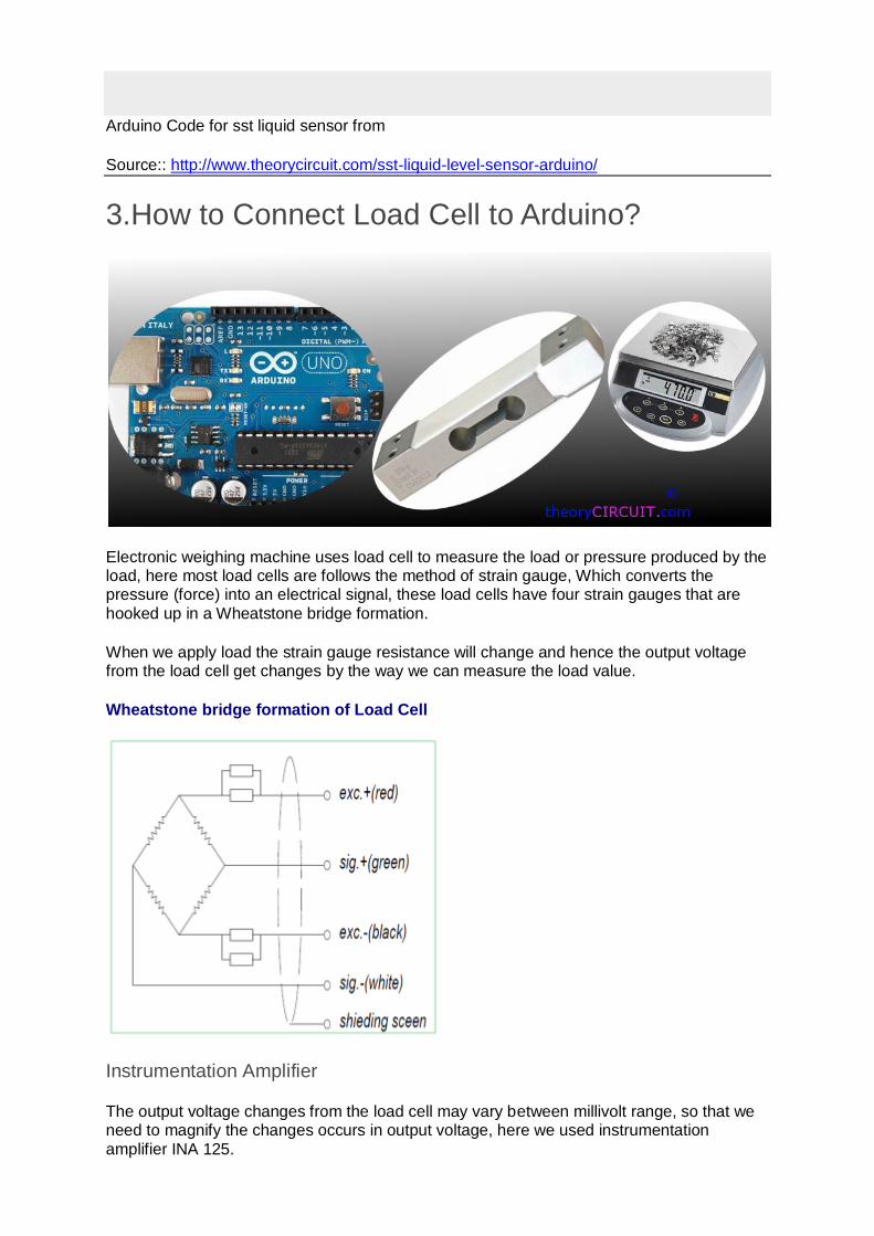
3.How to Connect Load Cell to Arduino?
Electronic weighing machine uses load cell to measure the load or pressure produced by the load, here most load cells are follows the method of strain gauge, Which converts the pressure (force) into an electrical signal, these load cells have four strain gauges that are
hooked up in a Wheatstone bridge formation.
When we apply load the strain gauge resistance will change and hence the output voltage from the load cell get changes by the way we can measure the load value.
Wheatstone bridge formation of Load Cell
Instrumentation Amplifier
The output voltage changes from the load cell may vary between millivolt range, so that we need to magnify the changes occurs in output voltage, here we used instrumentation
amplifier INA 125.

This is a low power, high accuracy instrumentation amplifier with a precision voltage reference. It provides complete bridge excitation and precision differential input amplification on a single integrated circuit.
Pinout diagram of INA125
The INA125 is a 16 pin DIP (Dual Inline Package) IC. It has two stages of amplifier with
reference amplifier.
Load Cell Interfacing Schematic
Connect load cell pins to the instrumentation amplifier as shown in the schematic diagram.
RED : Excitation +
WHITE : Signal +

GREEN : Signal –
BLACK : Excitation –
The Resistor 10Ω connected between pin 8 & 9 is responsible for Gain of INA 125 instrumentation amplifier, the output is taken combined from Vo and Sense (Pin 10 & 11) and it is fed into Arduino analog pin A0. Here the need of power supply for load cell and instrumentation amplifier solved by Arduino power pins. This circuit is designed for getting
reading at serial terminal if you need to add display refer LCD interface with Arduino.
Arduino Code for Load Cell
// Load cells are linear. So once you have established two data pairs, you
can interpolate the rest.
// Step 1: Upload this sketch to your arduino board
// You need two loads of well know weight. In this example A = 10 kg. B =
30 kg
// Put on load A
// read the analog value showing (this is analogvalA)
// put on load B
// read the analog value B
// Enter you own analog values here
float loadA = 10; // kg
int analogvalA = 200; // analog reading taken with load A on the load cell
float loadB = 30; // kg
int analogvalB = 600; // analog reading taken with load B on the load cell

// Upload the sketch again, and confirm, that the kilo-reading from the
serial output now is correct, using your known loads
float analogValueAverage = 0;
// How often do we do readings?
long time = 0; //
int timeBetweenReadings = 200; // We want a reading every 200 ms;
void setup() {
Serial.begin(9600);
}
void loop() {
int analogValue = analogRead(0);
// running average - We smooth the readings a little bit
analogValueAverage = 0.99*analogValueAverage + 0.01*analogValue;
// Is it time to print?
if(millis() > time + timeBetweenReadings){
float load = analogToLoad(analogValueAverage);
Serial.print("analogValue: ");Serial.println(analogValueAverage);
Serial.print(" load: ");Serial.println(load,5);

time = millis();
}
}
float analogToLoad(float analogval){
// using a custom map-function, because the standard arduino map function
only uses int
float load = mapfloat(analogval, analogvalA, analogvalB, loadA, loadB);
return load;
}
float mapfloat(float x, float in_min, float in_max, float out_min, float
out_max)
{
return (x - in_min) * (out_max - out_min) / (in_max - in_min) + out_min;
}
Hookup Diagram
Source:: http://www.theorycircuit.com/how-to-connect-load-cell-to-arduino/
4.Interfacing Load Cell with Arduino using HX711
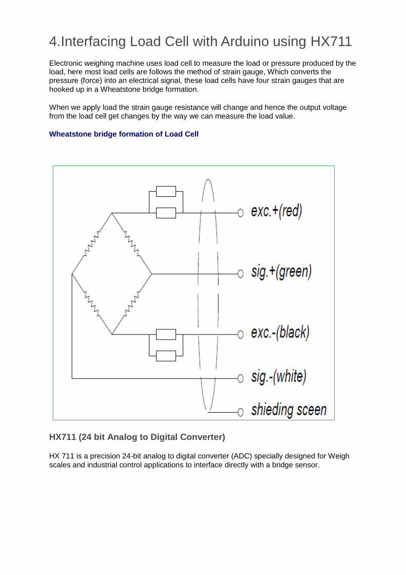
Electronic weighing machine uses load cell to measure the load or pressure produced by the load, here most load cells are follows the method of strain gauge, Which converts the pressure (force) into an electrical signal, these load cells have four strain gauges that are
hooked up in a Wheatstone bridge formation.
When we apply load the strain gauge resistance will change and hence the output voltage from the load cell get changes by the way we can measure the load value.
Wheatstone bridge formation of Load Cell
HX711 (24 bit Analog to Digital Converter)
HX 711 is a precision 24-bit analog to digital converter (ADC) specially designed for Weigh
scales and industrial control applications to interface directly with a bridge sensor.

Pinout of HX711
Arduino Hookup
Simply connect Load cell wires to the HX711 module based on their color, then connect DAT (Data) pin to Arduino Analog pin A1 and connect CLK (Clock) pin to Arduin0 Analog pin A0,
Put Vcc and Gnd supply from Arduino power source pins.
Arduino Code
// Hx711.DAT - pin #A1
// Hx711.CLK - pin #A0

#include "hx711.h"
Hx711 scale(A1, A0);
void setup() {
Serial.begin(9600);
}
void loop() {
Serial.print(scale.getGram(), 1);
Serial.println(" g");
delay(200);
}
This simple code brings output at serial port terminal of Arduino IDE.
Before compiling this code put HX711 Library into the Arduino IDE.
Source:: http://www.theorycircuit.com/interfacing-load-cell-arduino-using-hx711/

5.Add Sound Detector to Your Arduino Project
Knock? Knock! did you hear that sound, now you can add sound detection to your Arduino project, here I have used sparkfun Electret microphone Breakout board which is constructed with small microphone (100 Hz – 10KHz) and preamplifier. It detects and amplify the sounds of door knocks, claps, voice or any other sounds loud enough to picked up by the microphone.
Microphone Breakout
Here the Electret Mic capsule capturing sound wave between two conducting plates (one a
movable and the other fixed) and converting sound waves into electrical wave.

Microphone Breakout Schematic
The Electrical signals are amplified and appears in ―AUD‖ pin of breakout board. It can be picked up by the micro controller’s ADC.
The output at AUD pin orgin at half the supply voltage hence the ADC will ideally read 1/2
the full scale or in case 512 on a 10 bit ADC.
Arduino Mic Breakout Schematic

Arduino Hookup
Connect Vcc pin and Ground pin of breakout board to Arduino power supply pins (+5 and Gnd), and then connect AUD (sound output) pin of breakout board to Arduino’s Analog pin
A0.
Breakout — Arduino
Vcc –> +5V
Gnd –> Gnd
AUD –> A0
Here i have used the Arduino’s on board LED at digital pin 13, you can use any other pins as per your need.
Arduino Code for Sound Detection
Simple Code
int led = 13;
int threshold = 600; //Change This
int volume;
void setup() {
Serial.begin(9600); // Serial port begin
pinMode(led, OUTPUT);
}
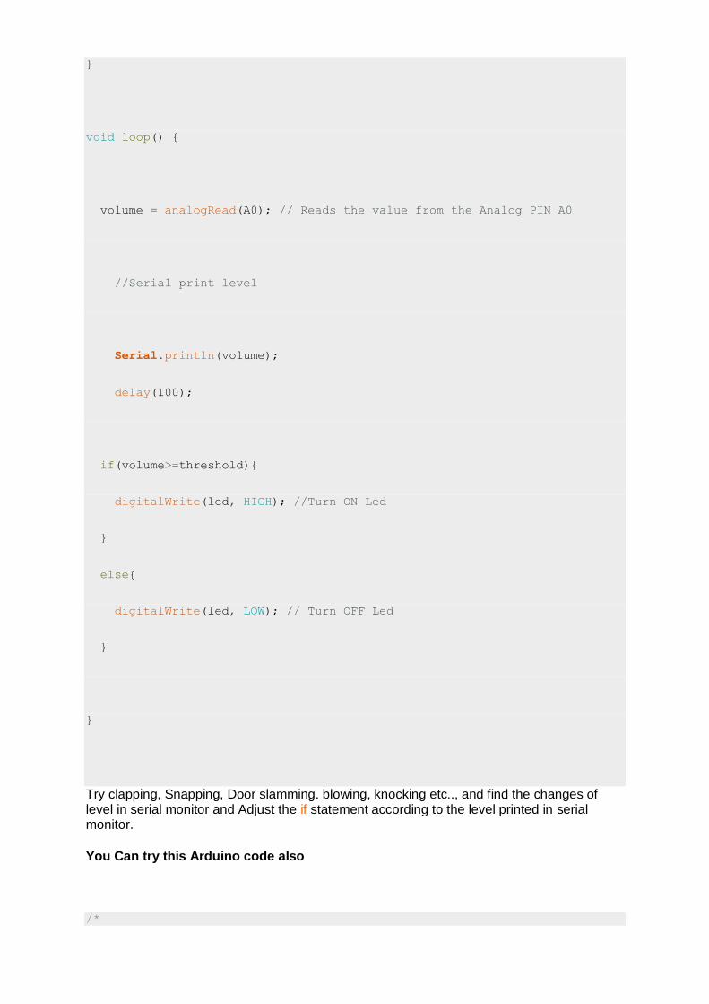
void loop() {
volume = analogRead(A0); // Reads the value from the Analog PIN A0
//Serial print level
Serial.println(volume);
delay(100);
if(volume>=threshold){
digitalWrite(led, HIGH); //Turn ON Led
}
else{
digitalWrite(led, LOW); // Turn OFF Led
}
}
Try clapping, Snapping, Door slamming. blowing, knocking etc.., and find the changes of level in serial monitor and Adjust the if statement according to the level printed in serial monitor.
You Can try this Arduino code also
/*
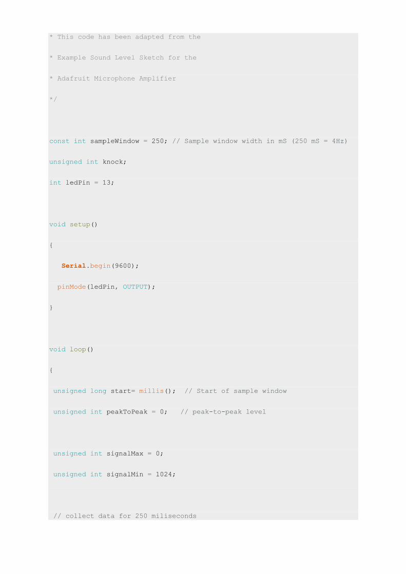
* This code has been adapted from the
* Example Sound Level Sketch for the
* Adafruit Microphone Amplifier
*/
const int sampleWindow = 250; // Sample window width in mS (250 mS = 4Hz)
unsigned int knock;
int ledPin = 13;
void setup()
{
Serial.begin(9600);
pinMode(ledPin, OUTPUT);
}
void loop()
{
unsigned long start= millis(); // Start of sample window
unsigned int peakToPeak = 0; // peak-to-peak level
unsigned int signalMax = 0;
unsigned int signalMin = 1024;
// collect data for 250 miliseconds

while (millis() - start < sampleWindow)
{
knock = analogRead(0);
if (knock < 1024) //This is the max of the 10-bit ADC so this loop
will include all readings
{
if (knock > signalMax)
{
signalMax = knock; // save just the max levels
}
else if (knock < signalMin)
{
signalMin = knock; // save just the min levels
}
}
}
peakToPeak = signalMax - signalMin; // max - min = peak-peak amplitude
double volts = (peakToPeak * 3.3) / 1024; // convert to volts
Serial.println(volts);
if (volts >=1.0)
{
//turn on LED
digitalWrite(ledPin, HIGH);

delay(500);
Serial.println("Knock Knock");
}
else
{
//turn LED off
digitalWrite(ledPin, LOW);
}
}
Source:: http://www.theorycircuit.com/add-sound-detector-arduino-project/


![1.0 INTRODUCTION IJSER · PDF fileArduino can sense the surroundings by receiving input signal from a variety of sensors . and can affect its environment via actuators [5]](https://img.pdfslide.net/doc/110x75/5a8273607f8b9a9d308e0544/10-introduction-ijser-can-sense-the-surroundings-by-receiving-input-signal-from.jpg)