Embed Size (px)
Citation preview

Ardyani, T., Mohamed, A., Abu Bakar, S., Sagisaka, M., Umetsu, Y.,Hafiz Mamat, M., Khairul Ahmad, M., Abdul Khalil, H. P. S., King, S.M., Rogers, S. E., & Eastoe, J. (2020). Electrochemical exfoliation ofgraphite in nanofibrillated kenaf cellulose (NFC)/surfactant mixture forthe development of conductive paper. Carbohydrate Polymers, 228,[115376]. https://doi.org/10.1016/j.carbpol.2019.115376
Peer reviewed versionLicense (if available):CC BY-NC-NDLink to published version (if available):10.1016/j.carbpol.2019.115376
Link to publication record in Explore Bristol ResearchPDF-document
This is the author accepted manuscript (AAM). The final published version (version of record) is available onlinevia Elsevier at https://doi.org/10.1016/j.carbpol.2019.115376 . Please refer to any applicable terms of use of thepublisher.
University of Bristol - Explore Bristol ResearchGeneral rights
This document is made available in accordance with publisher policies. Please cite only thepublished version using the reference above. Full terms of use are available:http://www.bristol.ac.uk/red/research-policy/pure/user-guides/ebr-terms/

1
One-Pot Electrochemical Exfoliation of Graphene Oxide in Nanofibrillated
Kenaf Cellulose (NFC) for the Development of Conductive Paper
Tretya Ardyani1, Azmi Mohamed1,2*, Suriani Abu Bakar2, Masanobu Sagisaka3,
Yasushi Umetsu3 Mohamad Hafiz Mamat4, Mohd Khairul Ahmad5, H.P.S. Abdul
Khalil 6 Stephen King7, Sarah E. Rogers7, Julian Eastoe8
1Department of Chemistry, 2Nanotechnology Research Centre, Faculty of Science and
Mathematics, Universiti Pendidikan Sultan Idris, 35900 Tanjong Malim, Perak,
Malaysia
3Department of Frontier Materials Chemistry, Graduate School of Science and
Technology, Hirosaki University, Bunkyo-cho 3, Hirosaki, Aomori 036-8561, Japan
4NANO-SciTech Centre (NST), Institute of Science (IOS), Universiti Teknologi
MARA (UiTM), 40450 Shah Alam, Selangor, Malaysia
5Microelectronic and Nanotechnology – Shamsuddin Research Centre (MiNT-SRC),
Faculty of Electrical and Electronic Engineering, Universiti Tun Hussein Onn
Malaysia, 86400 Parit Raja, Batu Pahat, Johor, Malaysia
6School of Industrial Technology, Universiti Sains Malaysia, 11700 Gelugor, Penang,
Malaysia
7Rutherford Appleton Laboratory, ISIS Spallation Source, Chilton, Oxfordshire,
OX110QT, United Kingdom
8School of Chemistry, University of Bristol, Cantock’s Close, Bristol, BS8 1TS,
United Kingdom
*Corresponding author. Tel.: +601548797582; fax: +601548797296

2
Abstract
The effect of incorporating common dodecyl anionic and cationic surfactants such as
dodecyltrimethylammonium bromide (DTAB), dodecylethyldimethylammonium
bromide (DDAB), and sodium dodecylsulfate (SDS) in nanocomposites of reduced
graphene oxide and nanocellulose are described. The stabilization and electrical
properties of the nanocomoposites of reduced graphene oxide (RGO) and
nanofibrillated kenaf cellulose (NFC) were characterized using four-point probe
electrical conductivity measurements. Raman spectroscopy, field emission scanning
electron microscopy, and high-resolution transmission electron microscopy were used
to investigate dispersion morphology and quality RGO inside the NFC matrices.
Small-angle neutron scattering (SANS) was used to study the aggregation behavior of
the surfactant aqueous systems and RGO dispersions. The cationic surfactant DTAB
proved to be the best choice for stabilization of RGO in NFC, giving enhanced
electrical conductivity of five orders of magnitude higher than the neat NFC. The
results highlight the effects of hydrophilic surfactant moieties on structure, stability
and properties of RGO/NFC composites.
Keywords: ionic surfactant, reduced graphene oxide, electrochemical exfoliation,
conductive paper, nanocellulose

3
1. Introduction
There is a strong drive for using nanocellulose in the development of polymer
nanocomposites, which offer various benefits including low environmental impact.
Recently researchers have been attempting to incorporate graphene into nanocellulose
matrices for applications requiring good electrical properties, such as conducting
papers (Hou, Xu, & Li, 2018; Wang, Bian, Ji, & Yang, 2018). The most common
approach to fabricate graphene/nanocellulose paper is by blending, where the
electrical conductivity of the resulting composite is highly dependent on the amount
of incorporated graphene and the dispersion quality (Nguyen Dang & Seppälä, 2015;
Peng, Meng, Niu, & Lu, 2012; Wang, Drzal, Qin, & Huang, 2015). Numerous studies
on graphene/nanocellulose papers have reported remarkable electrical conductivities.
Wang et al. a conductivity of 1.98 x 10⁻¹ S cm-1 with a graphene content of 20 wt%
(Wang et al., 2018). Previously Ye et al. (2016) also noted similar conductivities (1.50
x 10-1 S cm-1), albeit with a higher graphene content (50 wt%). Xiong et al. (2016)
claimed to reach an electrical conductivity of nearly 50 S cm-1 with
nanocellulose/graphene oxide nanomembranes at 56.8 wt% graphene content.
One of the merits of nanocomposite-reinforced by graphene is the possibility
of reaching high and stable electrical conductivities. Problems arise however, because
of the difficulty of dispersing graphene in nanocellulose. Furthermore, improving the
dispersibility of nanocellulose in aqueous phases is also particularly challenging.
Although the aforementioned studies have reported highly conductive
graphene/nanocellulose papers, high filler loadings are required, having negative
economic and environmental impacts. In most cases, surface modifications are

4
required, or added electrolytes or alkaline conditions are necessary to achieve stable
nanocellulose systems (Zhang, Liu, Zheng, & Zhu, 2012; Zhou & Zhang, 2000).
Functionalization of graphene is also commonly used to overcome the challenges of
stabilizing dispersions (Georgakilas et al., 2012). Although nanocellulose itself is
considered an environmentally safe material, chemical functionalization can
compromise this advantage. On the other hand, chemical functionalization of
graphene can be expected to affect the π-conjugated network responsible for
distributing electrical flow (Mohamed et al., 2016). Therefore, in an effort to seek an
economical and effective approach, the focus here is on the use of added surfactants
to help improve compatibility between graphene and nanocellulose.
As such, surfactants can be considered as an appealing alternative and
numerous articles have discussed this approach for enhancing surface properties of
graphene and carbon nanotubes (Mohamed et al., 2016; Tkalya, Ghislandi, de With,
& Koning, 2012). The same concept could be useful for nanocellulose-graphene
composites. Our previous work introduced a simple method for obtaining stable
graphene/nanocellulose dispersions with the help of ionic liquid type surfactants
(Mohamed et al., 2018a). The resulting dispersions can be further cast to generate
graphene/nanocellulose conductive papers. Applying similar concepts, and to explore
surfactants that are compatible with both graphenes and nanocellulose, the focus here
is shifted to cationic surfactants. Since the first report of surfactants for graphene
processing emerged, various types have been tested (Lin et al., 2016; Mohamed et al.,
2016; Tkalya et al., 2012). Most studies use anionic surfactants, whereas works with
cationic surfactants are more limited. In early research, a range of quaternary
ammonium cationic surfactants were used to prepare surfactant-intercalated graphite
AZMI IS IT GRAPHITE OR GRAPHENE – CHECK AND CORRECT THIS? oxide

5
(Matsuo, Niwa, & Sugie, 1999). They reported an ability to control interlayer spacing
by changing the surfactant type and concentration. Fourier transform infrared (FTIR)
spectroscopy results suggested intermolecular interactions between surfactants and the
oxygens of graphite oxide. Later, others demonstrated successful exfoliation of
graphite assisted by cetyltrimethylammonium bromide (CTAB) to yield few layered
graphene sheets (Vadukumpully, Paul, & Valiyaveettil, 2009). In a different study,
this surfactant was observed to increase dispersion quality of reduced graphene oxide
(RGO) in natural rubber latex (NRL) matrices through conventional mixing.
Enhancements of several properties were claimed, although the electrical conductivity
was only moderately improved (Matos, Galembeck, & Zarbin, 2014).
Regarding studies with nanocellulose, the majority of surfactants studied are
anionic and nonionic (Tardy et al., 2017). A comprehensive understanding of how
ionic surfactants affect physicochemical properties would, therefore, underpin the
knowledge of the structure–performance relationships of ionic surfactants. To date,
despite limited examples (Tardy et al., 2017), literature reports of systematic studies
comparing anionic and cationic surfactants for composites of graphene and
nanocellulose still remain scarce. This current study investigates how interfacial
interactions, system stabilization and physicochemical properties are influenced by
choice of surfactant. Two different cationic surfactants are investigated here, both
bearing C12 hydrophobic chains (Table 1): dodecyltrimethylammonium bromide
(DTAB) and dodecylethyldimethylammonium bromide (DDAB). From the quaternary
ammonium series, DDAB would be the most appropriate to benchmark the
performance of DTAB as these surfactants only differ by substitution of a methyl
group on DTAB with a longer ethyl chain on the polar head. To provide a comparable
alternative, the C12 chain anionic sodium dodecylsulfate (SDS) is also included in the

6
study. The results will help to identify efficient commercially available cationic and
ionic surfactants for nanocellulose-graphene composites.
Table 1
Chemical structures of surfactants used in this study
Abbreviation Chemical structure and name
DTAB
Dodecyltrimethylammonium bromide
DDAB
Dodecylethyldimethylammonium bromide
SDS
Sodium dodecylsulfate
2. Materials and methods
2.1 Materials
Dodecyltrimethylammonium bromide (DTAB) and Dodecylethyldimethylammonium
bromide (DDAB) were purchased from Acros Organics and used without further
purification. Sodium dodecylsulfate (SDS; Systerm) was used as received.
Nanofibrillated kenaf cellulose was a gift from the Forest Research Institute Malaysia.
Graphite rods with diameter of 10 mm and length of 150 mm were obtained from
Goodfellow, GmBH. Hydrazine hydrate was obtained from Merck and used as
received.
7
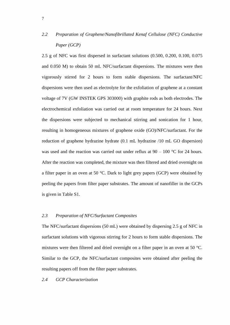
2.2 Preparation of Graphene/Nanofibrillated Kenaf Cellulose (NFC) Conductive
Paper (GCP)
2.5 g of NFC was first dispersed in surfactant solutions (0.500, 0.200, 0.100, 0.075
and 0.050 M) to obtain 50 mL NFC/surfactant dispersions. The mixtures were then
vigorously stirred for 2 hours to form stable dispersions. The surfactant/NFC
dispersions were then used as electrolyte for the exfoliation of graphene at a constant
voltage of 7V (GW INSTEK GPS 303000) with graphite rods as both electrodes. The
electrochemical exfoliation was carried out at room temperature for 24 hours. Next
the dispersions were subjected to mechanical stirring and sonication for 1 hour,
resulting in homogeneous mixtures of graphene oxide (GO)/NFC/surfactant. For the
reduction of graphene hydrazine hydrate (0.1 mL hydrazine /10 mL GO dispersion)
was used and the reaction was carried out under reflux at 90 – 100 °C for 24 hours.
After the reaction was completed, the mixture was then filtered and dried overnight on
a filter paper in an oven at 50 °C. Dark to light grey papers (GCP) were obtained by
peeling the papers from filter paper substrates. The amount of nanofiller in the GCPs
is given in Table S1.
2.3 Preparation of NFC/Surfactant Composites
The NFC/surfactant dispersions (50 mL) were obtained by dispersing 2.5 g of NFC in
surfactant solutions with vigorous stirring for 2 hours to form stable dispersions. The
mixtures were then filtered and dried overnight on a filter paper in an oven at 50 °C.
Similar to the GCP, the NFC/surfactant composites were obtained after peeling the
resulting papers off from the filter paper substrates.
2.4 GCP Characterization

8
The electrical conductivities of GCPs were measured by a four-point probe method
(Keithley 2636A). The morphologies and microstructure of GCPs were observed
under a field emission electron microscope (FESEM, Hitachi SU8020). Raman
spectroscopy was carried out using a Renishaw InVia micro Raman system
spectrophotometer with a 514 nm argon-ion laser source. To visualize the embedded
microstructures of nanocellulose papers, high resolution transmission electron
microscopy (HRTEM JEOL 2100F) was used. Prior to HRTEM imaging, the GCPs
were cryo-ultramicrotomed with a diamond knife to give sections with nominal
thickness ~80 nm.
2.5 Zeta potential measurements
Zeta potential measurements were performed using a ELSZ-1000 Zeta-potential and
Particle Size Analyzer (Photal Otsuka Electronics) employing the Smoluchowski
equation and 1 peak Lorentz fitting. Measurements were carried out with a flow cell
at a sampling time of 400 μs, cumulative number 7, measuring angle 15º, temperature
25 ºC, pin hole size 50 μm, and cell constant 70.000 cm-1. Properties of aqueous
mixtures including refractive index of 1.3328, viscosity of 0.8878 cP, and dielectric
constant of 78.3 were used for calculation of zeta potential. Zeta potential values were
finally obtained as average values of 10 runs for each sample.
2.6 Small-angle neutron scattering (SANS)
Small-angle neutron scattering (SANS) studies were carried out on the time-of-flight
LOQ instrument at ISIS, UK. The accessible Q range was 0.007 – 0.23 Å-1, arising
from incident neutron wavelengths of λ = 2.2 – 10 Å. Absolute intensities for I(Q)
(cm-1) were determined to within 5% by measuring the scattering from a partially

9
deuterated polymer standard. The samples were prepared in 2 mm path-length quartz
cells and held in a thermostatted automatic sample changer at 25°C. Data have been
fitted using the SASView interactive fitting program by fixing scattering length
densities and known parameters as constant values. Unknown structural parameters
were allowed to float during the fitting process to obtain an optimized fit as required
by the different scattering laws.
3. Results and discussion
3.1 Electrical properties of graphene/NFC paper (GCP)
Greyish papers disk having diameters of 6.50 – 6.57 cm and 0.14 – 0.18 mm in
thickness were obtained. The four-probe electrical conductivities of the papers at
room temperature are summarized in Table 2. The relationship between electrical
conductivity achieved by GCPs and surfactant concentration, on the other hand, is
depicted in Fig. S1. As expected, the use of surfactants for improving RGO dispersion
inside the NFC matrices leads to enhancements in electrical properties of NFC paper.
Comparisons between samples with and without RGO clearly show that this is due to
the presence of RGO dispersed in NFC matrix.

10
Table 2 1
Electrical conductivities of NFCs with and without RGO stabilized by surfactants 2
3
Sample
Surfactant concentration (M)
0.050 0.075 0.100 0.200 0.500
Electrical conductivity of nanocomposites (S cm1)
NFC/RGO/DTAB 3.12 x 10⁻⁸ ± 9.98 x 10⁻⁷ 1.11 x 10⁻⁶ ± 1.02 x 10⁻⁷
2.56 x10⁻⁵ ± 1.08 x 10⁻⁵
1.28 x 10⁻⁴ ± 9.85 x 10⁻⁵ 5.44 x 10⁻⁵ ± 1.11 x 10⁻⁵
NFC/RGO/DDAB 4.46 x 10⁻⁸ ± 8.96 x 10⁻⁷
4.76 x 10⁻⁸ ± 2.78 x 10⁻⁷
1.43 x 10⁻⁷ ± 1.43 x 10⁻⁸
1.02 x 10⁻⁶ ± 8.73 x 10⁻⁷ 9.75 x 10⁻⁷ ± 1.29 x 10⁻⁷
NFC/RGO/SDS 2.82 x 10⁻⁸ ± 8.45 x 10⁻⁹
2.08 x 10⁻⁸ ± 7.98 x 10⁻¹⁰
3.09 x 10⁻⁷ ± 2.86 x 10⁻⁸
8.92 x 10⁻⁷ ± 1.30 x 10⁻⁷ 9.95 x 10⁻⁷ ± 6.78 x 10⁻⁸
NFC 1.97 x 10⁻¹⁰ ± 1.59 x 10⁻⁹
NFC/DTAB 1.78 x 10⁻⁹ ± 9.15 x 10⁻⁸
5.83 x 10⁻⁹ ± 2.05 x 10⁻⁸
9.82 x 10⁻⁹ ± 6.14 x 10⁻⁸
5.94 x 10⁻⁹ ± 7.82 x 10⁻⁸ 1.37 x 10⁻⁹ ± 8.10 x 10⁻⁸
NFC/DDAB 3.23 x 10⁻⁹ ± 1.49 x10⁻⁸
3.67 x 10⁻⁹ ± 4.36 x 10⁻⁸
7.32 x 10⁻⁹ ± 5.32 x 10⁻⁸
7.62 x 10⁻⁹ ± 4.81 x 10⁻⁸ 7.17 x 10⁻⁹ ± 8.28 x 10⁻⁸
NFC/SDS 6.03 x 10⁻⁹ ± 2.04 x 10⁻⁸ 5.76 x 10⁻⁹ ± 1.01 x 10⁻⁸
9.32 x 10⁻⁹ ± 8.24 x 10⁻⁸
8.88 x 10⁻⁹ ± 5.21 x 10⁻⁸ 9.45 x 10⁻⁹ ± 1.24 x 10⁻⁹

11
In general, anionic surfactant SDS, brings only moderate improvements in the 1
electrical properties of GCPs, with the highest conductivity achieved at 9.95 x 10⁻⁷ S 2
cm-1. Meanwhile, cationic surfactant DTAB improves conductivity by six orders of 3
magnitude, achieving 1.28 x 10⁻⁴ at surfactant concentration of 0.200 M. There are no 4
surprises to the increasing electrical conductivities on increasing surfactant 5
concentration, as a similar trend was also found elsewhere (Mohamed et al., 2018b; 6
Suriani, Nurhafizah, Mohamed, Zainol, & Masrom, 2015). Interestingly however, the 7
effects of surfactants reaches a limit, as was seen previous literatures (Coleman, 2009; 8
Wang, Yi, & Shen, 2016). The presence of high surfactant concentration in the 9
nanocomposites was presumed to enhance the electrical conductivity of the 10
nanocomposites (Tkalya, Ghislandi, Alekseev, Koning, & Loos, 2010). 11
A complex picture emerges from the measurements with DDAB surfactant 12
(1.02 x 10⁻⁶ S cm-1). With a slightly higher carbon number for DDAB, it gives a rather 13
limited electrical conductivity enhancement with only four orders magnitude 14
improvement compared to the neat NFC (1.97 x 10⁻¹⁰ S cm-1). It might be expected 15
that longer surfactant tails (higher C – number) will occupy a larger area on the 16
graphene surfaces (Adamczyk, Para, & Warszyński 1999; Manne, Cleveland, Gaub, 17
Stucky, & Hansma, 1994; Matsuo et al., 1999; McCoy et al., 2018; Moulik, Haque, 18
Jana, & Das, 1996). Thus, it could provide a greater barrier to avoid water contact at 19
the graphene surfaces, which may lead to destabilization. However, this is not 20
observed in the current study. 21
In earlier work, Matsuo and co-workers revealed that the graphite [AZMI IS 22
IT GRAPHITE ORE GRAPHENE?? – CHECK AND CORRECT THIS PLEASE] 23
oxide interlayer distance concurrently increases with surfactant alkyl chain length 24
(Matsuo et al., 1999). This may lessen the tendency of adjacent graphene sheets to 25
12
aggregate. It was presumed that the surfactant forms bilayers between the graphite 1
oxide sheets, where longer tails (larger areas occupied by surfactant tails) would 2
hinder dense packing on the GO surfaces. Studying dispersions of graphene with ionic 3
surfactants, Smith and co-workers also noted an improved dispersion stability using a 4
cationic surfactant with higher C – number (Smith, Lotya, & Coleman, 2010). 5
Although the longer tail achieves a lower dispersion concentration, it provides greater 6
stability, after 7 days of observation. This idea again is inconsistent with the trend 7
reported here. 8
Looking at electrical conductivity of GCPs over all surfactant concentrations, 9
DTAB maintains higher conductivity compared to SDS and DDAB. It therefore can 10
be suggested that the stability of GCP suspensions are sensitive to the chemical 11
structure of hydrophilic moieties of the stabilizing surfactants. The result is in 12
agreement with Quennouz and co-workers who also highlighted the effect of 13
surfactant hydrophilic structure on the stability of surfactant/cellulose nanofibril 14
suspensions, where SDS requires 20-fold higher concentration than DTAB to give the 15
same suspension stability (Quennouz, Hashmi, Choi, Kim, & Osuji, 2016). This 16
phenomenon can also be explained from the viewpoint of RGO and surfactant 17
affinity. McCoy et al. (2018) revealed that the headgroup type is the overriding factor 18
for affinity between surfactants and RGO surfaces, as cationic surfactants proved to 19
be more attractive for RGO surfaces than anionics. 20
Looking at the conductivity values of GCPs, the results obtained here are over 21
a similar range with other related studies (see Table S2) (Feng, Zhang, Shen, Yoshino, 22
& Feng, 2012; Kiziltas et al., 2016; Wang et al., 2015). Rather than obtaining high 23
conductivity values with a high amount of nanofiller (Wang et al., 2018; Ye et al., 24
2016), here it is shown that an improvement on the NFC nanocomposite electrical 25

13
properties can be expected at considerably low nanofiller contents (see Table S1 and 1
S2) with the help of surfactant. All in all, the cationic DTAB provided significantly 2
higher conductivity enhancement compared to DDAB and anionic SDS. In these 3
systems, when using surfactants with the same alkyl chain length, it seems that 4
cationic surfactants are the best option for the resulting nanocomposite properties. 5
6
3.2 Raman spectroscopy of graphite and graphene/NFC paper (GCP) 7
Raman spectroscopy was used to analyze the structural changes experienced by 8
graphite in GCPs. The prominent peaks of graphene based materials located at 1350 9
(D-peak) and 1580 cm-1 (G-peak) (Ferrari, 2007) are displayed in Fig. 1. The peak 10
positions of each sample are summarized in Table S3 (Supplementary material). 11
Graphite has a negligibly small and weak D-peak. The G-peak located at 1581 cm-1 is 12
clearly more intense than the D-peak. As the graphite] was exfoliated, oxidized, and 13
subjected to chemical treatment (reduction process to restore the sp2-conjugated 14
network), the D and G peak evolve significantly. In the GCPs samples, the D-peak is 15
clearly identifiable with prominent peaks. At the higher wavenumber side (2D area; 16
2700 cm-1), it can be seen that graphite displayed a single broad peak, while the GCPs 17
have slimmer and less sharp peaks with a bump like region. The existence of the 18
bump like areas might be due to the presence of chemically induced defects during the 19
GCP fabrication process (Kaniyoor & Ramaprabhu, 2012). 20
21

14
1
Fig. 1. Raman spectra of the graphite (a) and GCPs stabilized with cationic 2
surfactants: (b) DTAB, (c) DDAB and anionic surfactant: (d) SDS. Surfactant 3
concentration: 0.100 M. 4
5
As a consequence of the oxidization and reduction process, the defects 6
increase, leading to an increase in the D-peak intensity (ID). To characterize the lattice 7
structure of RGO, the ratio of Raman intensities (defect to graphitic ratio; ID/IG) was 8
calculated, where lower ID/IG indicates lower defects in the graphene structure. As can 9
be seen, the ID/IG ratio of graphene presented in the GCP significantly increased 10
compared to the starting material (graphite), implying that the exfoliation and 11
reduction process has been successful (Chua & Pumera, 2013; Kudin et al., 2008). 12
Comparison of ID/IG value between the GCPs shows that the sample with SDS gives 13
the highest Raman ratio. The results suggest that RGO in GCPs stabilized by SDS has 14
the highest level of remnant functional groups, and the sp2-carbon basal plane is less 15
healed during the reduction process compared to DTAB or DDAB. Correlating the 16
ID/IG ratio with electrical properties of the GCPs reveals a pattern of higher 17

15
conductivity for GCP with lower defect ratios. Here, the choice of surfactant can be 1
linked with the quality of RGO produced during the fabrication process, whereby 2
better surfactants produce RGO with lower defect densities, and thus higher electrical 3
conductivities. Although such trends are noted, it can be seen that the ID/IG difference 4
between DTAB and DDAB is close. Hence, more detail is necessary to evaluate 5
factors affecting the different performance of surfactants in this series, particularly for 6
DTAB and DDAB. 7
8
3.3 Morphology of graphene/NFC paper (GCP) 9
The internal structure of RGO dispersions inside NFC matrices was 10
investigated by FESEM. Fig. 2 shows FESEM images of the GCPs as well as the 11
NFC. As shown in Fig. 2a, NFC exhibits a random arrangement of tap-like fibrils 12
having a diameter of 32 – 49 nm without any preferential orientation. In the case of 13
GCPs (Fig. 2b – d), various morphologies of nanofiller can be seen decorating the 14
NFC fibers. Different regions of NFC fibrillated networks can be seen, and RGO can 15
be identified as aggregates (Fig. 2c and d) or more defined stacked layered structures 16
(Fig. 2b). 17
Comparison of the GCPs morphologies with different surfactants at low 18
magnification images (Fig. 2b – d) revealed that RGOs produced using DTAB and 19
DDAB have considerably larger sizes compared with SDS. GCPs stabilized with 20
DTAB appear to feature large flaked RGO regions, although, closer observation (Fig. 21
2b’) reveals less defined sheets edges with stacked structure. Meanwhile, RGO in 22
GCPs with DDAB (Fig. 2c and c’) and SDS (Fig. 2d and d’) exist as clumped 23
aggregated structures both in high and low magnification imaging, unlike those 24
observed with DTAB. Based on the FESEM, results it is considered that the RGOs 25

16
can be successfully dispersed into the NFC matrices. The results also match well with 1
the trends in electrical conductivity discussed above. 2
3
4
5
6
a a’
b b’
c c’
d’ d

17
Fig. 2. FESEM images of nanofibrillated kenaf cellulose (NFC) (a and a’) and GCP: 1
with DTAB (b and b’), with DDAB (c and c’), and with SDS (d and d’). The selected 2
areas for higher magnification imaging are marked by the dashed squares. 3
4
It is known that the electrical conductivity of nanocomposite is affected by the 5
dispersion state of the nanofiller inside the host. In this case, more uniformly 6
distributed nanofillers are expected to give higher electrical conductivities (Mao, Zhu, 7
& Jiang, 2012; Tkalya et al., 2012). In addition to this, the electrical properties also 8
depend on the quality of graphene, in other words, using more exfoliated graphene 9
sheets leads to higher electrical conductivity (Mao et al., 2012). Visualization of the 10
RGOs inside NFC matrices using FESEM revealed different morphologies resulting 11
from different surfactants. From these images it can be deduced that DTAB offers 12
better exfoliation and stabilization than SDS and DDAB, yielding defined flakes 13
rather than clumped aggregated structures. 14
The results and trends obtained here agreed well with the electrical 15
conductivity measurements described above. However, linking the morphology of the 16
RGOs inside the GCPs does not lead to such obvious trends as for the electrical 17
conductivity measurements. All in all, by comparing the morphology of the GCPs, it 18
is therefore reasonable to assume that DTAB is the best dispersant out of the 19
surfactants used in this study. 20
21

18
1
Fig. 3. HRTEM images of the GCP stabilized by DTAB: (a) Typical morphologies at 2
low magnification (b) higher magnification. Grey areas are NFC fibers. Note that 3
many RGO sheets are embedded throughout the NFC matrix (c) Edge view of RGO 4
sheets. 5
6
7
FESEM images have highlighted the different RGO morphologies dispersed in 8
NFC matrices. In order to understand the embedded microstructure of RGO inside 9
NFC stabilized by DTAB surfactant, an ultrathin section of GCP was observed under 10
HRTEM. Observations at low magnification (Fig. 3 (a and b) indicate the presence of 11
RGO (dark lines), supporting the FESEM images. An enlarged view (Fig. 3c) 12
revealed that RGO was present as few-layer sheets. Hence, it is seen that DTAB is a 13
good surfactant for this application. 14
3.4 Studying the role of surfactant for dispersion stability: Zeta (ζ)-potential 15
measurements 16
In aqueous dispersions, the electrical double layer is an important feature and zeta 17
potential measurements are useful to asses stability (Hunter, 1981). Addition of 18
electrolytes may affect the distribution of surface charge, depending on the nature of 19
added component. Efforts to make a comparison with literature values however are 20
restricted due to the very limited number of studies focused on colloidal stability of 21
these related systems. 22
To provide understanding of the surfactant stabilization and its relationship, if 23
any, to the efficiencies in elevating the composite properties, the zeta potentials of 24
(a) (b) (c)
RGO
RGO Cellulose
Few-layer
Few-layer

19
RGO dispersions stabilized by DTAB, DDAB, and SDS are given in Table 3. The 1
RGO dispersion quality and the ability of surfactant to ensure stabilization scales very 2
well with the measured zeta potentials. The sign of zeta potential (negative or 3
positive) reflects the type of surfactant adsorbed onto the material. As a rule of thumb, 4
system with a zeta potential of |10 – 20| mV is close to the threshold of agglomeration 5
whereas a value of |30| mV is accepted for colloidal stability (Lotya et al., 2009). 6
Between the cationic surfactants, although DTAB displayed a zeta potential 7
above the standard of stable colloidal system +32 mV, its cousin DDAB exhibited a 8
zeta potential of +23 mV which can be classified as less stable. In contrast to the 9
results obtained here, Smith et al. noted very good graphene dispersion stability with 10
quaternary ammonium bromide surfactants (> +45 mV) (Smith et al., 2010). 11
Interestingly, SDS clearly outperforms DTAB and DDAB in terms of electrical 12
barrier strength, displaying a zeta potential value of -43 mV. 13
Looking only at the results from zeta potential measurements, SDS is 14
considered to offer significantly more stability than DTAB and DDAB, and so SDS 15
should offer better electrical properties than both cationic surfactants. The results 16
from the electrical conductivity measurements in Table 2 however did not follow this 17
order. Perhaps there are other factors why the reinforcing factor of RGO with SDS is 18
attenuated. Intermolecular interactions between each component: RGO, surfactants, 19
and NFC therefore need to be further investigated to explain the behavior. These 20
observations may facilitate better understanding for selecting more suitable surfactant 21
types for the development of conductive papers of nanocellulose and graphene. 22
23

20
3.5 Effect of headgroup type on surfactant aggregation structure: small-angle 1
neutron scattering (SANS) study of surfactant solutions and reduced graphene 2
oxide (RGO)-stabilized surfactant systems 3
Surfactants will self-assemble into micelles in the aqueous phase driven by the 4
tendency of hydrophobic tails to minimize contact with water. When carbon 5
nanomaterials are also present, surfactants can adsorb on the surfaces in various 6
configurations (Lin et al., 2016; Tkalya et al., 2012; Vaisman, Wagner, & Marom, 7
2006). Thus, it is important to describe how the surfactants organize on RGO 8
surfaces, and for this small angle neutron scattering (SANS) studies have been 9
conducted. SANS studies can give quantitative information about the shape and size 10
of the surfactant aggregation structures in aqueous phases and in RGO dispersions. 11
Such information will contribute to understanding the interactions between RGO and 12
surfactants, as well as provide insight into the structure and nature of the adsorbed 13
surfactant layers. 14
Fig. 4 shows SANS profiles for the surfactant solutions and RGO dispersions 15
with DTAB, DDAB, and SDS. The scattering intensity I(Q) typically is related to 16
nanostructure: the features contributing to I(Q) are shape and size of the particles, 17
usually described as particle form factor P(Q). With charged particle dispersions, the 18
scattering profile is also affected by inter-particle interactions which can be either 19
attractive or repulsive in nature, accounted for by the structure factor S(Q). For more 20
detailed discussions on SANS, readers are directed elsewhere (Feigin & Svergun, 21
1987; Hollamby, 2013). 22
23

21
Q / Å-1
0.01 0.1
I(Q
) /
cm-1
10-3
10-2
10-1
100
SDS
DDAB
DTAB
1
Q / Å-1
0.01 0.1
I(Q
) /
cm-1
10-3
10-2
10-1
100
SDS + RGO
DTAB + RGO
DDAB + RGO
2
3
Fig. 4. SANS profiles for (a) DTAB, DDAB, and SDS solutions and (b) the RGO 4
dispersions. [surfactant] = 0.030 M and T = 25 °C. Lines are model fits for charged 5
spherical or ellipsoidal micelles with the Hayter-Penfold S(Q)) model. Characteristic 6
error bars are shown for the lowest intensity samples. 7
8
9
10
11
12
13
(a)
(b)

22
1
Table 3 2
Model fit parameters for SANS dataa 3
Sample ζ-potential
(mV)
Model Rsphere
(Å)
Ra
(Å)
X ± 0.2
DTAB - Ellipsoid - 15.0 1.5
DDAB - Ellipsoid - 11.0 2.2
SDS - Sphere 22.0
DTAB + RGO +32 ± 1 Ellipsoid - 14.0 1.7
DDAB + RGO +23 ± 1 Sphere 17.0 - -
SDS + RGO -43 ± 4 Sphere 24.0 - -
a[surf.] = 0.030 M. Charged micelles were fitted with interparticle structure factor 4
S(Q) for Hayter-Penfold model 5
6
7
For SDS, the scattering profile agrees well with a model for charged spherical 8
micelles, consistent with literature (Paul et al., 2005; Yurekli, Mitchell, & 9
Krishnamoorti, 2004). The interparticle interaction was fitted to a Hayter-Penfold 10
S(Q) model (Hayter & Penfold, 1983), with the fit parameters listed in Table 3 Data 11
analysis through scattering law fitting gives the micellar radius Rsphere to be 22.0 Å, 12
consistent with previous works (Magid, Li, & Butler, 2000; Mohamed et al., 2018a; 13
Wang et al., 2016; Yurekli et al., 2004). 14
Measurements with the cationic surfactant DTAB gave I(Q) characteristic of 15
ellipsoidal micelles experiencing repulsive interactions, modelled by the Hayter-16
Penfold interparticle factor, S(Q). An axial micelle radius, Ra, of 15.0 Å was obtained 17
with an aspect ratio, X, 1.5 indicating that the micelles are oblate spherical (Ra < Rb). 18
The result is in concordant with literature values where the radius lie between 15.0 to 19

23
19.0 Å at surfactant concentration of 0.02 – 0.20 M (Brown et al., 2012; Griffith & 1
Notley, 2012; Mahajan, Vohra, Kaur, & Aswal, 2008; McCoy et al., 2018). Bergstorm 2
and Pederssen (1998, 1999) also revealed the aggregation of ellipsoidal micelles, 3
although in their study, the structure factor P(Q) is more suited to the tri-axial 4
ellipsoidal model. 5
The scattering profile with DDAB surfactant is also indicative of an ellipsoidal 6
form factor, with a peak owing to the electrostatic interparticle stabilization of 7
micelles. Fitting the SANS data give an axial radius of 11.0 Å with an ellipsoidal axis 8
ratio 2.2. It seems that the secondary axis of DDAB is larger compared to that for the 9
DTAB surfactant. This increase in micellar radius can be attributed to the length of 10
the surfactant tail. Previous SANS experiments on cationic ammonium halide 11
surfactants revealed an increase of micellar radii with longer hydrophobic tails (Aswal 12
& Goyal, 1998; Berr, 1987; McCoy et al., 2018). 13
Parallel SANS experiments with the same surfactant concentration in D2O 14
were conducted, and the results are compared to those for pure surfactant solutions to 15
reveal any structural changes when RGO is incorporated. There is no substantial 16
difference in scattering over the Q range, compared with the pure surfactant solutions. 17
Hence, the curves can be adequately fitted with the ellipsoidal and spherical models as 18
appropriate. As can be referred in Table 3, the micellar dimensions are broadly the 19
same for DTAB and SDS. This is surprising for DTAB, as it is the most efficient 20
surfactant in the series. A micelle shape transition, or changes in dimensions, are to be 21
expected when such low dimensional material is added to the system, as those found 22
in the existing literature (Granite, Radulescu, & Cohen, 2012; McCoy et al., 2018; 23
Wang et al., 2004). McCoy et al. found significant differences in the scattering profile 24
in the low Q region (0.003 – 0.02 Å), following the Q-2 indicative of planar flat RGO 25

24
sheets, which was not found in this study (McCoy et al., 2018). In contrast, DDAB 1
transitioned into different micellar shape, and an ellipsoidal to spherical transition was 2
observed. If only considering the axial radius of ellipsoids, the presence of RGO 3
resulted in a larger micellar radius 17.0 Å. In general, although analysis of the SANS 4
data revealed physically realistic parameters, it is rather challenging to draw a firm 5
trend or pattern on the self-assembly of the surfactants on RGO surfaces. 6
The existing literature suggests certain arrangements of surfactant molecules 7
on graphene surfaces as characteristic of positive surfactant – graphene interactions, 8
hence the aggregation structure will adopt hemi-micelles, or cylindrical structures (for 9
the case of CNTs) (Lin et al., 2016; Lin, Shih, Strano, & Blankschtein, 2011; 10
Matarredona et al., 2003). With this picture in mind, it can be suggested that the 11
interactions of dodecyl tails and graphene surfaces are less favorable. The surfactants 12
are presumed to just randomly adsorb on graphene surface, enough to prevent the 13
adjacent neighboring RGO sheets from aggregating and destabilizing. 14
15
3.6 Comparison of cationic vs. anionic surfactants at graphene and NFC 16
interfaces: A proposed mechanism 17
A significant advancement in studying the adsorption of surfactant at carbon 18
nanomaterial surfaces has been the use of small-angle neutron scattering and 19
molecular dynamic simulations (Lin et al., 2011; McCoy et al., 2018; Wang, 2009). 20
With these techniques, insight into how the surfactant adsorbs can be obtained. In this 21
study, the cationic DTAB came out as the most efficient for stabilizing the RGO/NFC 22
composites. Interestingly, although the zeta potential is suggestive of a “stable 23
dispersion”, SANS data do not show any structural changes for the micellar 24
properties, giving a relatively similar micelle radius. General observations on 25

25
colloidal characterization (SANS and zeta-potential) showed that although giving 1
higher conductivity enhancement, DTAB still behaves in a similar fashion with the 2
SDS and DDAB. 3
There is strong evidence on the relationship between stability and the tendency 4
of surfactants to follow the curvature of dispersed materials (Matarredona et al., 2003; 5
Vaisman et al., 2006; Wang, 2009; Wang et al., 2004). However, this is not the case 6
here; therefore, a model of surfactant fully-covered graphene surfaces as has been 7
used to explain aggregation behavior in a previous study (Mohamed et al., 2018a,b) 8
must be ruled out here. 9
In an earlier study, Yurekli et al. (2004) assumed a structureless random 10
adsorption of SDS on single walled carbon nanotube (SWCNT) walls being 11
responsible for the aqueous phase dispersion stability. This stems from the constant 12
micelle shape and size upon SWCNT addition. Instead of adopting cylindrical 13
micelles, SDS molecules were suggested to adsorb at the graphene sheets of CNTs 14
randomly with no preferential arrangement. This picture be used to explain the 15
behavior of all the surfactants used in this study. A schematic figure of the surfactant 16
self-assembly is now given in Fig. 5. 17
18

26
1
Fig. 5. Proposed mechanism of ionic dodecyl surfactant arrangement in RGO/NFC 2
composites. 3
4
In the stable dispersions surfactant may exist as individual molecules, in 5
micelles or adsorbed to graphene surfaces (Sa & Kornev, 2011; Wang et al., 2004). 6
The ideal situation is that the surfactant fully wraps the graphene surfaces, minimizing 7
contact with water, hence adopting the shape of graphene either as stacked disk or 8
stacked bilayer aggregates. This can be achieved when the attractions between 9
surfactant tails or headgroups and graphene surfaces are strong enough. In this case, 10
the interaction between the surfactants and graphene surfaces may be less favorable, 11
hence the limited number of surfactant monomers adsorbed on graphene surfaces 12
(McCoy et al., 2018; Wang, Han, Wang, Qin, & Guo, 2008). 13
The surfactant tails are thought to adsorb perpendicularly toward graphene 14
surfaces, or lying flat to maximize the hydrophobic interactions with no preferential 15
adsorption site (Fig. 5 (II)). The charged headgroups are expected to face toward the 16
aqueous phase and interact with the hydrophilic segments of nanocellulose 17

27
(Bandyopadhyay, Shelley, Tarek, Moore, & Klein, 1998; Ducker & Grant, 1996; 1
Shah, Chiu, & Sinnott, 2006; Wang et al., 2008). Due to the limited adsorbed 2
surfactant on graphene, hence the surfactant molecules do not form aggregation 3
structures on top of graphene surface, in turn; the associated surfactant in micelles 4
dominates the aqueous phase. This may explain the absence of micellar structural 5
transitions in the presence of graphene as observed by SANS. 6
It has been widely suggested that anionic surfactants are more efficient for 7
stabilizing graphene dispersions (Lin et al., 2016; Shih, Lin, Strano, & Blankschtein, 8
2015; Smith et al., 2010; Texter, 2014). Notley (2012), however proved otherwise. 9
Using a continuous surfactant addition approach, cationic surfactants (CTAB, DTAB, 10
TTAB) were revealed to be on a par with anionic surfactant (SDS) in terms of 11
produced dispersed graphene concentration. In the graphene dispersion literature 12
(Texter, 2014), when the surfactant comprises similar long carbon chains, it is 13
actually very difficult to say which of the stabilizers is better, as different works lead 14
to different conclusions. 15
It is known that the positioning of surfactants at an interface between water 16
and another phase is a result of an interfacial energy minimization for the surfactant, 17
water and graphene (Coleman, 2009). Therefore, the ability of surfactants to provide 18
stabilization may be assessed through surfactant geometrical considerations, namely 19
fractional free volume (FFV) (Stone, Smith, da Rocha, Rossky, & Johnston, 2004). 20
This concept was initially introduced to understand the design of effective surfactants 21
for microemulsion studies (Mohamed et al., 2010). As such it is used to quantify the 22
bulkiness of surfactants at an interface, hence the space available for interpenetration 23
between two incompatible materials can be assessed. In polymer science, free volume 24

28
is important parameter to define the permeability of polymers. Here, the FFV is 1
defined in Equation (1) as 2
FFV 1h
V
tA= − (1) 3
Where, V is the volume of a surfactant tail, t is the thickness of the interface, 4
and Ah is the interfacial area per headgroup. To implement a succinct discussion, the 5
justification made for the FFV calculation as well as detail of each parameter is given 6
in Supplementary Material (Table S4 and S5). It is hypothesized that lower FFV will 7
minimize the penetration of water at graphene surfaces, hence giving higher 8
conductivity of the GCPs. 9
As can be seen in Table S6, surfactant performance in stabilizing RGO and 10
NFC dispersions, that is optimum electrical conductivity, does show a general trend 11
with FFV. The electrical conductivity in fact increases as FFV decreases. Lower FFV 12
should favor a lower area for water penetration on graphene surfaces and thus greater 13
dispersion stability. In support of this interpretation, analysis using fluorescence 14
spectroscopy revealed that the void space near DTAB headgroup is less than around 15
SDS, suggesting larger water permeability with SDS (Karukstis, Suljak, Waller, 16
Whiles, & Thompson, 1996). Calculation of headgroup surface area through modeling 17
also revealed larger area occupied by DTAB than SDS (Karukstis et al., 1996). In 18
general, the results show that the surfactant performance at graphene – water interface 19
correlates with FFV. 20
As well as surfactant structure and architecture, it is interesting to consider the 21
influence of surfactant activity for stabilizing these composites. A recent review has 22
summarized extensive work on the interaction of cationic and anionic surfactants with 23
nanocellulose (Tucker, Petkov, Penfold, & Thomas, 2012). The nature of surfactant 24

29
adsorption onto NFC surfaces is broadly similar to other hydrophilic/hydrophobic 1
solid surfaces; except there is an additional aspect to be considered arising from 2
cellulose swelling (Tucker et al., 2012). 3
By measuring the adsorption isotherm, Biswas and Chattoraj (1997) proposed 4
that the interaction between homologous ammonium halide surfactant involved 5
hydrophobic interactions between surfactant tails and cellulose surfaces (Biswas & 6
Chattoraj, 1997). Meanwhile, based on the adsorption of CTAB onto anionic 7
nanofibrillated cellulose, others have postulated that the formation of surfactant 8
bilayers switches the cellulose nanofibrils to be more hydrophilic (Xhanari, Syverud, 9
Chinga-Carrasco, Paso, & Stenius, 2011). The interaction was suggested to be driven 10
by electrostatic interactions between anionic carboxyls present in the nanofibrils with 11
the positively charged CTAB headgroups. Using SDS, Tucker et al. observed the 12
adsorption of surfactant molecules toward the hydrophilic part of negatively charged 13
cellulose at concentrations greater than 2 x 10⁻³ M (Tucker et al., 2012). Others have 14
proposed the formation of bridging-mediated fibrous networks between SDS and 15
negatively charged nanofibrils (Quennouz et al., 2016). Such networks can be induced 16
by the presence of favorable, albeit weak, interactions between groups in SDS and 17
negatively charged species in cellulose nanofibrils. These studies proved that 18
regardless of the headgroup type, ionic surfactants will be able to display affinity with 19
cellulose surfaces. 20
Tardy et al. (2017) listed plausible reasons why cationic surfactants 21
outperform anionics for stabilizing these dispersions. The rate of anionic surfactant 22
adsorption at the cellulose-water interface was said to be lower than that of cationic 23
surfactants (Paria, Manohar, & Khilar, 2004). Even when compared to other 24
surfactant types, the kinetics are the fastest and the forces of interaction are the 25

30
strongest between cellulosic materials and cationic surfactants (Tardy et al., 2017). 1
Studying the rheology of cellulose nanofibrils, Quennouz and co-workers noted that 2
DTAB needed only approximately one eighth of the SDS concentration to form 3
homogeneous clear gel suspensions (Quennouz et al., 2016). The underlying reason 4
for the higher DTAB efficiency, and for cationic surfactants in general, is possibly 5
increased affinities between surfactants and nanocellulose surfaces, facilitating the 6
dispersion of RGO inside NFC matrices. 7
8
4. Conclusions 9
The advantages in utilizing electrochemical approaches to produce dispersed reduced 10
graphene oxide (RGO) have already established (Parvez et al., 2014; Suriani et al., 11
2016; Suriani et al., 2015). Our previous study has shown that it is possible to obtain 12
electrically conductive NFC paper stabilized by specialized ionic liquid-type 13
surfactants (Mohamed et al., 2018a). Here, more common readily available 14
commercial surfactants are employed instead, and effects of headgroup chemistry 15
with two model ionic surfactants –anionic and cationic - was investigated in terms of 16
dispersion stability, electrical conductivity enhancement, and aggregation properties. 17
There is a distinct graphene-compatibility of the anionic and cationic surfactants, with 18
DTAB being the most efficient stabilizer. Although the chemical structures between 19
DTAB and DDAB differ by only substitution of a headgroup ethyl moiety in place of 20
a methyl group, it is still not clear why DDAB does not perform as well as its 21
homologue DTAB. Considering these two analogues have very similar solution 22
properties (Fisicaro, Biemmi, Compari, Duce, & Peroni, 2007), DDAB would be 23
expected to give similar dispersion stability as DTAB. 24

31
One way to consider adsorption is in terms of adsorption and surface 1
aggregation structures (Mohamed et al., 2018a,b; Tkalya et al., 2012; Vaisman et al., 2
2006). The strength and type of interfacial interaction can be expected to influence the 3
morphology of aggregates formed on RGO surfaces. Nevertheless, here a similar 4
micelle structure was seen in both the aqueous solutions and RGO dispersions. The 5
stabilization mechanism was then proposed to be random adsorption of surfactant 6
molecules on graphene surfaces, co-existing with the background surfactant micelles. 7
Because the surfactants bear the same C12 hydrophobic tails, it is reasonable to 8
assume that the any changes in adsorption and stabilization are a result of hydrophilic 9
headgroup structure. A readily calculated surfactant parameter, namely FFV is seen to 10
be useful for describing the different behavior between anionic and cationic 11
surfactants. A decrease in FFV favors a more stable system and thus higher electrical 12
conductivity of the composites. The results underline that the choice of surfactant 13
headgroup significantly affects the affinity with RGO and nanocellulose. 14
15
Acknowledgements 16
The work funded under grants from Universiti Pendidikan Sultan Idris Rising Star 17
Research Grant (Grant Code: 2019-0118-103-01). This project was supported by 18
JSPS [KAKENHI, Grant-in-Aid for Young Scientists (A), No. 23685034], 19
KAKENHI, Grant-in-Aid for Scientific Research (B), No. 26289345, Fund for the 20
Promotion of Joint International Research (Fostering Joint International Research) 21
No. 15KK0221, Grant-in-Aid for Challenging Research (Exploratory), No.17K19002] 22
and Leading Research Organizations (RCUK [through EPSRC EP/I018301/1], ANR 23
[13-G8ME-0003]) under the G8 Research Councils Initiative for Multi-lateral 24
Research Funding—G8-2012. The authors thank the Science and Technology 25
32
Facilities Council for allocation of beam time, travel and consumables (experiment 1
number RB1710004). This work benefited from the use of the SasView application, 2
originally developed under NSF Award DMR-0520547. SasView also contains code 3
developed with funding from the EU Horizon 2020 programme under the SINE2020 4
project Grant No 654000. 5
6
References 7
Adamczyk, Z., Para, G., & Warszyński , P. (1999). Influence of ionic strength on 8
surface tension of cetyltrimethylammonium bromide. Langmuir, 15, 8383-9
8387. 10
Aswal, V. K., & Goyal, P. S. (1998). Mixed micelles of alkyltrimethylammonium 11
halides a small-angle neutron-scattering study. Physica B: Condensed Matter, 12
245, 73-80. 13
Bandyopadhyay, S., Shelley, J. C., Tarek, M., Moore, P. B., & Klein, M. L. (1998). 14
Surfactant aggregation at a hydrophobic surface. The Journal of Physical 15
Chemistry B, 102, 6318-6322. 16
Bergström, M., & Pedersen, J. S. (1998). Small-angle neutron scattering (SANS) 17
study of aggregates formed from aqueous mixtures of sodium dodecyl sulfate 18
(SDS) and dodecyltrimethylammonium bromide (DTAB). Langmuir, 14, 19
3754-3761. 20
Bergström, M., & Pedersen, J. S. (1999). Structure of pure SDS and DTAB micelles 21
in brine determined by small-angle neutron scattering (SANS). Physical 22
Chemistry Chemical Physics, 1, 4437-4446. 23

33
Berr, S. S. (1987). Solvent isotope effects on alkytrimethylammonium bromide 1
micelles as a function of alkyl chain length. Journal of Physical Chemistry, 2
91, 4760-4765. 3
Biswas, S. C., & Chattoraj, D. K. (1997). Polysaccharide-surfactant interaction. 1. 4
Adsorption of cationic surfactants at the cellulose-water interface. Langmuir, 5
13, 4505-4511. 6
Brown, P., Bushmelev, A., Butts, C. P., Cheng, J., Eastoe, J., Grillo, I., Heenan, R. K., 7
& Schmidt, A. M. (2012). Magnetic control over liquid surface properties with 8
responsive surfactants. Angewandte Chemie International Edition, 124, 2464-9
2466. 10
Chua, C. K., & Pumera, M. (2013). Reduction of graphene oxide with substituted 11
borohydrides. Journal of Materials Chemistry A, 1, 1892-1898. 12
Coleman, J. N. (2009). Liquid-phase exfoliation of nanotubes and graphene. 13
Advanced Functional Materials, 19, 3680-3695. 14
Ducker, W. A., & Grant, L. M. (1996). Effect of substrate hydrophobicity on 15
surfactant surface-aggregate geometry. The Journal of Physical Chemistry, 16
100, 11507-11511. 17
Feigin, L. A., & Svergun, D. I. (1987). Structure analysis by small-angle X-ray and 18
neutron scattering. (1st ed). New York: Springer, (Chapter 1). 19
Feng, Y., Zhang, X., Shen, Y., Yoshino, K., & Feng, W. (2012). A mechanically 20
strong, flexible and conductive film based on bacterial cellulose/graphene 21
nanocomposite. Carbohydrate polymers, 87, 644-649. 22
Ferrari, A. C. (2007). Raman spectroscopy of graphene and graphite: Disorder, 23
electron-phonon coupling, doping and nonadiabatic effects. Solid State 24
Communications, 143, 47-57. 25

34
Fisicaro, E., Biemmi, M., Compari, C., Duce, E., & Peroni, M. (2007). 1
Thermodynamics of aqueous solutions of dodecyldimethylethylammonium 2
bromide. Journal of Colloid and Interface Science, 305, 301-307. 3
Georgakilas, V., Otyepka, M., Bourlinos, A. B., Chandra, V., Kim, N., Kemp, K. C., 4
Hobza, P., Zboril,R., & Kim, K. S. (2012). Functionalization of graphene: 5
covalent and non-covalent approaches, derivatives and applications. Chemical 6
Reviews, 112, 6156-6214. 7
Granite, M., Radulescu, A., & Cohen, Y. (2012). Small-angle neutron scattering from 8
aqueous dispersions of single-walled carbon nanotubes with Pluronic F127 9
and poly (vinylpyrrolidone). Langmuir, 28, 11025-11031. 10
Griffith, A., & Notley, S. M. (2012). pH dependent stability of aqueous suspensions 11
of graphene with adsorbed weakly ionisable cationic polyelectrolyte. Journal 12
of Colloid and Interface Science, 369, 210-215. 13
Hayter, J. B., & Penfold, J. (1983). Determination of micelle structure and charge by 14
neutron small-angle scattering. Colloid & Polymer Science, 261, 1022-1030. 15
Hollamby, M. J. (2013). Practical applications of small-angle neutron scattering. 16
Physical Chemistry Chemical Physics, 15, 10566-10579. 17
Hou, M., Xu, M., & Li, B. (2018). Enhanced electrical conductivity of cellulose 18
nanofiber/graphene composite paper with a sandwich structure. ACS 19
Sustainable Chemistry & Engineering, 6, 2983-2990. 20
Hunter, R. J. (1981). Zeta potential in colloid science: principles and applications. 21
(1st ed.). London: Academic Press, (Chapter 2). 22
Kaniyoor, A., & Ramaprabhu, S. (2012). A Raman spectroscopic investigation of 23
graphite oxide derived graphene. AIP Advances, 2, 032183. 24

35
Karukstis, K. K., Suljak, S. W., Waller, P. J., Whiles, J. A., & Thompson, E. H. Z. 1
(1996). Fluorescence analysis of single and mixed micelle systems of SDS and 2
DTAB. The Journal of Physical Chemistry, 100, 11125-11132. 3
Kiziltas, E. E., Kiziltas, A., Rhodes, K., Emanetoglu, N. W., Blumentritt, M., & 4
Gardner, D. J. (2016). Electrically conductive nano graphite-filled bacterial 5
cellulose composites. Carbohydrate polymers, 136, 1144-1151. 6
Kudin, K. N., Ozbas, B., Schniepp, H. C., Prud'Homme, R. K., Aksay, I. A., & Car, 7
R. (2008). Raman spectra of graphite oxide and functionalized graphene 8
sheets. Nano Letters, 8, 36-41. 9
Lin, S., Shih, C.-J., Sresht, V., Rajan, A. G., Strano, M. S., & Blankschtein, D. (2016). 10
Understanding the colloidal dispersion stability of 1D and 2D materials: 11
perspectives from molecular simulations and theoretical modeling. Advances 12
in Colloid and Interface Science, 244, 36-53. 13
Lin, S., Shih, C.-J., Strano, M. S., & Blankschtein, D. (2011). Molecular insights into 14
the surface morphology, layering structure, and aggregation kinetics of 15
surfactant-stabilized graphene dispersions. Journal of the American Chemical 16
Society, 133, 12810-12823. 17
Lotya, M., Hernandez, Y., King, P. J., Smith, R. J., Nicolosi, V., Karlsson, L. S., 18
Blighe, F. M., De, S., Wang, Z., McGovern, I. T., Duesberg, G. S., & 19
Coleman, J. N. (2009). Liquid phase production of graphene by exfoliation of 20
graphite in surfactant/water solutions. Journal of the American Chemical 21
Society, 131, 3611-3620. 22
Magid, L. J., Li, Z., & Butler, P. D. (2000). Flexibility of elongated sodium dodecyl 23
sulfate micelles in aqueous sodium chloride: a small-angle neutron scattering 24
study. Langmuir, 16, 10028-10036. 25

36
Mahajan, R. K., Vohra, K. K., Kaur, N., & Aswal, V. K. (2008). Organic additives 1
and electrolytes as cloud point modifiers in octylphenol ethoxylate solutions. 2
Journal of surfactants and detergents, 11, 243-250. 3
Manne, S., Cleveland, J. P., Gaub, H. E., Stucky, G. D., & Hansma, P. K. (1994). 4
Direct visualization of surfactant hemimicelles by force microscopy of the 5
electrical double layer. Langmuir, 10, 4409-4413. 6
Mao, C., Zhu, Y., & Jiang, W. (2012). Design of electrical conductive composites: 7
tuning the morphology to improve the electrical properties of graphene filled 8
immiscible polymer blends. ACS Applied Materials & Interfaces, 4, 5281-9
5286. 10
Matarredona, O., Rhoads, H., Li, Z., Harwell, J. H., Balzano, L., & Resasco, D. E. 11
(2003). Dispersion of single-walled carbon nanotubes in aqueous solutions of 12
the anionic surfactant NaDDBS. The Journal of Physical Chemistry B, 107, 13
13357-13367. 14
Matos, C. F., Galembeck, F., & Zarbin, A. J. G. (2014). Multifunctional and 15
environmentally friendly nanocomposites between natural rubber and 16
graphene or graphene oxide. Carbon, 78, 469-479. 17
Matsuo, Y., Niwa, T., & Sugie, Y. (1999). Preparation and characterization of 18
cationic surfactant-intercalated graphite oxide. Carbon, 37, 897-901. 19
McCoy, T. M., de Campo, L., Sokolova, A. V., Grillo, I., Izgorodina, E. I., & Tabor, 20
R. F. (2018). Bulk properties of aqueous graphene oxide and reduced graphene 21
oxide with surfactants and polymers: adsorption and stability. Physical 22
Chemistry Chemical Physics, 20, 16801-16816. 23

37
Mohamed, A., Ardyani, T., Abu Bakar, S., Brown, P., Hollamby, M., Sagisaka, M., & 1
Eastoe, J. (2016). Graphene-philic surfactants for nanocomposites in latex 2
technology. Advances in Colloid and Interface Science, 230, 54-69. 3
Mohamed, A., Ardyani, T., Abu Bakar, S., Sagisaka, M., Umetsu, Y., Hamon, J. J., 4
Rahim, B. A., Esa, S. R., Abdul Khalil, H. P. S., Mamat, M. H., King, S., & 5
Eastoe, J. (2018b). Rational design of aromatic surfactants for 6
graphene/natural rubber latex nanocomposites with enhanced electrical 7
conductivity. Journal of Colloid and Interface Science, 516, 34-47. 8
Mohamed, A., Ardyani, T., Abu Bakar, S., Sagisaka, M., Umetsu, Y., Hussin, M. R. 9
M., Ahmad, M. K., Mamat, M. H., King, S., Czajka, A., Hill, C., & Eastoe, J. 10
(2018a). Preparation of conductive cellulose paper through electrochemical 11
exfoliation of graphite: The role of anionic surfactant ionic liquids as 12
exfoliating and stabilizing agents. Carbohydrate polymers, 201, 48-59. 13
Mohamed, A., Trickett, K., Chin, S. Y., Cummings, S., Sagisaka, M., Hudson, L., 14
Nave, S., Dyer, R., Rogers, S., Heenan, R. K., & Eastoe, J. (2010). Universal 15
Surfactant for Water, Oils, and CO2. Langmuir, 26, 13861-13866. 16
Moulik, S. P., Haque, M. E., Jana, P. K., & Das, A. R. (1996). Micellar properties of 17
cationic surfactants in pure and mixed states. The Journal of Physical 18
Chemistry, 100, 701-708. 19
Nguyen Dang, L., & Seppälä, J. (2015). Electrically conductive 20
nanocellulose/graphene composites exhibiting improved mechanical 21
properties in high-moisture condition. Cellulose, 22, 1799-1812. 22
Paria, S., Manohar, C., & Khilar, K. C. (2004). Effect of cationic surfactant on the 23
adsorption characteristics of anionic surfactant on cellulose surface. Colloids 24
and Surfaces A: Physicochemical and Engineering Aspects, 232, 139-142. 25

38
Parvez, K., Wu, Z.-S., Li, R., Liu, X., Graf, R., Feng, X., & Müllen, K. (2014). 1
Exfoliation of graphite into graphene in aqueous solutions of inorganic salts. 2
Journal of the American Chemical Society, 136, 6083-6091. 3
Paul, A., Griffiths, P. C., Pettersson, E., Stilbs, P., Bales, B. L., Zana, R., & Heenan, 4
R. K. (2005). Nuclear magnetic resonance and small-angle neutron scattering 5
studies of anionic surfactants with macrocounterions: tetramethylammonium 6
dodecyl sulfate. The Journal of Physical Chemistry B, 109, 15775-15779. 7
Peng, H., Meng, L., Niu, L., & Lu, Q. (2012). Simultaneous reduction and surface 8
functionalization of graphene oxide by natural cellulose with the assistance of 9
the ionic liquid. The Journal of Physical Chemistry C, 116, 16294-16299. 10
Quennouz, N., Hashmi, S. M., Choi, H. S., Kim, J. W., & Osuji, C. O. (2016). 11
Rheology of cellulose nanofibrils in the presence of surfactants. Soft Matter, 12
12, 157-164. 13
Sa, V., & Kornev, K. G. (2011). Analysis of stability of nanotube dispersions using 14
surface tension isotherms. Langmuir, 27, 13451-13460. 15
Shah, K., Chiu, P., & Sinnott, S. B. (2006). Comparison of morphology and 16
mechanical properties of surfactant aggregates at water-silica and water-17
graphite interfaces from molecular dynamics simulations. Journal of Colloid 18
and Interface Science, 296, 342-349. 19
Shih, C.-J., Lin, S., Strano, M. S., & Blankschtein, D. (2015). Understanding the 20
stabilization of single-walled carbon nanotubes and graphene in ionic 21
surfactant aqueous solutions: large-scale coarse-grained molecular dynamics 22
simulation-assisted DLVO theory. The Journal of Physical Chemistry C, 119, 23
1047-1060. 24

39
Smith, R. J., Lotya, M., & Coleman, J. N. (2010). The importance of repulsive 1
potential barriers for the dispersion of graphene using surfactants. New 2
Journal of Physics, 12, 125008. 3
Stone, M. T., Smith, P. G., da Rocha, S. R. P., Rossky, P. J., & Johnston, K. P. 4
(2004). Low interfacial free volume of stubby surfactants stabilizes water-in-5
carbon dioxide microemulsions. Journal of Physical Chemistry B, 108, 1962-6
1966. 7
Suriani, A. B., Nurhafizah, M. D., Mohamed, A., Masrom, A. K., Sahajwalla, V., & 8
Joshi, R. K. (2016). Highly conductive electrodes of graphene oxide/natural 9
rubber latex-based electrodes by using a hyper-branched surfactant. Materials 10
& Design, 99, 174-181. 11
Suriani, A. B., Nurhafizah, M. D., Mohamed, A., Zainol, I., & Masrom, A. K. (2015). 12
A facile one-step method for graphene oxide/natural rubber latex 13
nanocomposite production for supercapacitor applications. Materials Letters, 14
161, 665-668. 15
Tardy, B. L., Yokota, S., Ago, M., Xiang, W., Kondo, T., Bordes, R., & Rodes, O. J. 16
(2017). Nanocellulose-surfactant interactions. Current Opinion in Colloid & 17
Interface Science, 29, 57-67. 18
Texter, J. (2014). Graphene dispersions. Current Opinion in Colloid & Interface 19
Science, 19, 163-174. 20
Tkalya, E. E., Ghislandi, M., Alekseev, A., Koning, C., & Loos, J. (2010). Latex-21
based concept for the preparation of graphene-based polymer nanocomposites. 22
Journal of Materials Chemistry, 20, 3035-3039. 23
Tkalya, E. E., Ghislandi, M., de With, G., & Koning, C. E. (2012). The use of 24
surfactants for dispersing carbon nanotubes and graphene to make conductive 25
40
nanocomposites. Current Opinion in Colloid & Interface Science, 17, 225-1
232. 2
Tucker, I. M., Petkov, J. T., Penfold, J., & Thomas, R. K. (2012). Interaction of the 3
anionic surfactant SDS with a cellulose thin film and the role of electrolyte 4
and poyelectrolyte. 2 Hydrophilic cellulose. Langmuir, 28, 10223-10229. 5
Vadukumpully, S., Paul, J., & Valiyaveettil, S. (2009). Cationic surfactant mediated 6
exfoliation of graphite into graphene flakes. Carbon, 47, 3288-3294. 7
Vaisman, L., Wagner, H. D., & Marom, G. (2006). The role of surfactants in 8
dispersion of carbon nanotubes. Advances in Colloid and Interface Science, 9
128-130, 37-46. 10
Wang, F., Drzal, L. T., Qin, Y., & Huang, Z. (2015). Multifunctional graphene 11
nanoplatelets/cellulose nanocrystals composite paper. Composites Part B: 12
Engineering, 79, 521-529. 13
Wang, H. (2009). Dispersing carbon nanotubes using surfactants. Current Opinion in 14
Colloid & Interface Science, 14, 364-371. 15
Wang, H., Zhou, W., Ho, D. L., Winey, K. I., Fischer, J. E., Glinka, C. J., & Hobbie, 16
E. K. (2004). Dispersing single-walled carbon nanotubes with surfactants: a 17
small angle neutron scattering study. Nano Letters, 4, 1789-1793. 18
Wang, Q., Han, Y., Wang, Y., Qin, Y., & Guo, Z.-X. (2008). Effect of surfactant 19
structure on the stability of carbon nanotubes in aqueous solution. The Journal 20
of Physical Chemistry B, 112, 7227-7233. 21
Wang, R., Bian, H., Ji, H., & Yang, R. (2018). Preparation of lignocellulose/graphene 22
composite conductive paper. Cellulose, 25, 6139-6149. 23
Wang, S., Yi, M., & Shen, Z. (2016). The effect of surfactants and their concentration 24
on the liquid exfoliation of graphene. RSC Advances, 6, 56705-56710. 25

41
Xhanari, K., Syverud, K., Chinga-Carrasco, G., Paso, K., & Stenius, P. (2011). 1
Reduction of water wettability of nanofibrillated cellulose by adsorption of 2
cationic surfactants. Cellulose, 18, 257-270. 3
Xiong, R., Hu, K., Grant, A. M., Ma, R., Xu, W., Lu, C., Zhang, X., & Tsukruk, V. V. 4
(2016). Ultrarobust transparent cellulose nanocrystal-graphene membranes 5
with high electrical conductivity. Advanced Materials, 28, 1501-1509. 6
Ye, Y.-S., Zeng, H.-X., Wu, J., Dong, L.-Y., Zhu, J.-T., Xue, Z.-G., Zhou, X.-P., Xie, 7
X.-L., & Mai, Y.-W. (2016). Biocompatible reduced graphene oxide sheets 8
with superior water dispersibility stabilized by cellulose nanocrystals and their 9
polyethylene oxide composites. Green Chemistry, 18, 1674-1683. 10
Yurekli, K., Mitchell, C. A., & Krishnamoorti, R. (2004). Small-angle neutron 11
scattering from surfactant-assisted aqueous dispersions of carbon nanotubes. 12
Journal of the American Chemical Society, 126, 9902-9903. 13
Zhang, X., Liu, X., Zheng, W., & Zhu, J. (2012). Regenerated cellulose/graphene 14
nanocomposite films prepared in DMAC/LiCl solution. Carbohydrate 15
polymers, 88, 26-30. 16
Zhou, J., & Zhang, L. (2000). Solubility of cellulose in NaOH/urea aqueous solution. 17
Polymer Journal, 32, 866-870. 18
19
20
21