Embed Size (px)
Citation preview

Are Your Corrosion Control Practices Rusty?
Sponsored by

CONTENTS
Rethink Corrosion Monitoring 3
Successfully Combat Pipeline Corrosion 7
Efforts Pin Down Corrosion 11
INDUSTRY BRIEFING
www.ChemicalProcessing.com-2-

Rethink Corrosion MonitoringConsider permanently installed wireless non-intrusive ultrasonic sensors
By Jake Davies, Emerson Automation Solutions, Permasense Technologies
Many refineries rely on equipment well past origi-nal design life. These assets, some of which now have been in operation for double that time, face an ever-in-creasing risk of failure due to internal corrosion attack.
Corrosion in refineries often is caused by contami-nants in produced hydrocarbons that, over time, lead to deterioration of pipe and vessel walls. Loss of equip-ment integrity can result in unplanned downtime and costly repairs or, in the worst case, a catastrophic event posing major risk to personnel, the environment and stakeholder value.
Exacerbating the problem, many refineries no longer process the specific type of oil, such as sweet crude, they originally were designed to handle. The changing nature of oil feedstock magnifies corrosion problems in aging refineries.
For instance, in the U.S., refiners are taking advan-tage of the availability of light tight oils (LTOs), which afford significantly higher margins. The pro-duction of LTOs relies on the use of fracking fluids, a cocktail of chemicals for stimulating oil flow from the field. In many instances, these chemicals can end up in the crude oil feedstock to the refinery. In addition, the transportation of LTOs by railcar requires the addition of H2S passivator chemicals that can introduce other corrosion-related problems. These amine-based com-pounds can deposit as salts in the top section of crude towers, top pump-around and draw trays — with the resulting possibility of more corrosion.
Another example is Canadian oil sands crude, which has a high total acid number (TAN). Many of the world’s existing refineries were designed to process
crudes with a TAN of 0.3 mg KOH/g or less but lots of newer crudes have a TAN of 1 mg KOH/g or more.
High TAN crudes create naphthenic acid corrosion, a particularly aggressive and often localized form characterized by the “orange peel” effect (Figure 1). While this issue primarily affects crude and vacuum distillation units, the gas, oil and residue products fed to downstream conversion and hydroprocessing units also can exhibit TAN levels that cause problems in feed-section equipment fabricated from carbon steel.
Refiners have two principal mitigation strategies against corrosion: upgrading the metallurgy of many or all the susceptible areas, often to expensive high-nickel alloys or titanium; or using chemical corrosion inhibition treatment.
Both strategies should include online corrosion monitoring at critical locations to verify the state of the
Naphthenic Acid Corrosion
Figure 1. Crudes with a high total acid number cause corrosion in areas operating above about 200°C.
www.ChemicalProcessing.com-3-
CHEMICAL PROCESSING: SPECIAL REPORT
metallurgy upgrade or the inhibitor distribution and effectiveness. Alternatively, online corrosion monitor-ing can validate that the existing mitigation strategy is performing adequately.
ASSETS AT RISK
Refinery processing hardware prone to corrosion include sour-water strippers, crude and amine units, terminal jetties and many other assets.
Sour-water stripper tower corrosion and foul-ing from corrosion byproducts like iron sulfide are common operational problems compromising asset integrity. Tower and crude overhead sections are exposed to high levels of hydrogen sulfide and ammo-nia, and can experience excessive rates of ammonium bisulfide corrosion. High levels of cyanides from upstream units that concentrate in the overheads can compound corrosion risks (see Safeguard Sour-Water Strippers section below).
Free cyanides can be deposited in the wet gas stream, causing hydrogen blistering. Cyanides can destabilize any passivation (iron sulfide) layer, causing it to flake off as free iron sulfide, resulting in plugging and fouling.
Amine systems are subject to corrosion by both carbon dioxide and hydrogen sulfide in the vapor phase, the amine solution and the regenerator reflux — as well as from production of amine degradation products in the amine solution. In refineries specifi-cally, amine systems suffer from corrosion by several components such as ammonia, hydrogen cyanide and organic acids not generally found in natural and syn-thesis gases; some of these will accumulate at various points around the refinery amine system.
MONITORING CORROSION
Refineries can turn to two methods to measure corro-sion: probes and ultrasonic sensors.
Corrosion probes, which have been in use since the 1960s, rely on an intrusive element with a sacrificial tip
that sits in the process fluid. As the sacrificial tip cor-rodes, its electrical resistivity changes. The corrosion of the sacrificial tip is used to infer the level of corrosion being experienced by the surrounding equipment.
While simple to use, corrosion probes suffer from two disadvantages:1. The center-line measured corrosion at the tip may
not match the corrosion rate at the pipe wall.2. The tip often corrodes away after two to three years
while many refineries now operate five or more years between major turnarounds.
Ultrasonic measurement is a well-established technique for determining metal wall thickness. The technique involves the generation of ultrasound from a transducer placed directly onto the metal sur-face. The ultrasound travels through the metal until it is reflected off the back wall. The time difference between the sending and reflected signals correlates to the wall thickness.
Traditional ultrasonic manual inspection techniques only provide a snapshot of equipment integrity. Typi-cally, personnel take measurements every six months to five years. Such long intervals between measure-ments pose a significant safety risk because a serious
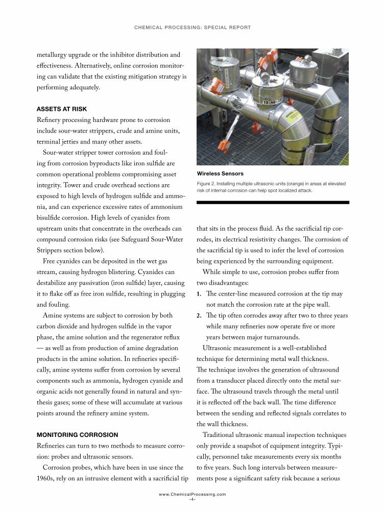
Wireless Sensors
Figure 2. Installing multiple ultrasonic units (orange) in areas at elevated risk of internal corrosion can help spot localized attack.
www.ChemicalProcessing.com-4-
CHEMICAL PROCESSING: SPECIAL REPORT

event can happen in a matter of hours or days. These traditional methods can’t provide the accuracy, qual-ity and frequency of data necessary to find problems, so mitigation can’t be optimized without interrupt-ing operations.
A NEWER OPTION
Today, refiners instead can opt for permanently installed, wireless ultrasonic wall-thickness-mon-itoring sensors for corrosion monitoring. The units generate on a continuous basis the data required to make proper decisions and provide this information directly to plant personnel.
These ultrasonic sensors are non-intrusive, so their installation cost is low, and can be mounted almost anywhere. Wireless data retrieval eliminates the need for cables, further decreasing installation and ongoing operating costs. Moreover, power packs should last until the next plant turnaround (typically, nine years’ service is achievable). The simplicity of installation and long power-pack life make ultrasonic sensors well suited for use in remote locations only accessible during turnarounds.
Each sensor has a measurement footprint of approx-imately 1 cm2, which is similar to the area required for manual ultrasound inspection. Thus, the probability of detecting localized corrosion attack using a single sensor is small. To increase the odds of detection, sensors often are installed as multi-point arrays at high-risk locations (Figure 2).
Process temperature variations affect all ultra-sound-based measurements due to the change in speed of sound through the metal. The latest generation of sensors uses an integrated thermocouple to measure the metal surface temperature and can automatically compensate the wall thickness data for tempera-ture variations.
Wall thickness data from these sensors can go directly via the wireless network to PC-based analysis packages such as Adaptive Cross Correlation (AXC)
software from Emerson (Figure 3). It can analyze and display information from dozens or even hundreds of corrosion sensors in a plant or refinery, and informs plant personnel when it discovers a problem.
Giving plant personnel access to this kind of cor-rosion information enables them to make the right decisions at the right time about when and where to carry out critical maintenance to support safer and more-economic operations.
Installing the non-intrusive corrosion sensors, a wireless network and PC-based software to process the data doesn’t require a multi-day project requiring asset shutdown. Actually, deploying a real-time wireless corrosion monitoring system at strategic locations on the outside of equipment only takes a matter of hours without any interruption to refinery operations.
IMPROVE CORROSION MONITORING
Beset with aging assets and crude feedstocks that are becoming ever-more aggressive from a corrosion standpoint, refineries face an increasing risk of equip-ment failure due to internal corrosion attack.
When equipped with timely information about cor-rosion problems, plant personnel can spot the dangers and take preventive action before corrosion presents a major operational risk. The enhanced insight provided by these real-time data allows refineries to improve safety, reduce operating costs and boost production
Wall Thickness
Figure 3. Analysis software can detect as little as 10 microns of wall loss.
www.ChemicalProcessing.com-5-
CHEMICAL PROCESSING: SPECIAL REPORT
from their aging assets. This can mean the difference between profit and loss, and between asset survival and extinction.
SAFEGUARD SOUR-WATER STRIPPERS
Sour-crude processing at refineries, unlike sweet-crude processing, often results in excessive levels of nitrogen, which leads to production of cyanides such as hydro-gen cyanide. Cyanides can create corrosion issues in the sour-water system. Produced in the downstream conversion units (such as the fluid catalytic cracker or delayed coker), cyanide compounds concentrate into the water phase of the main fractionator overhead.
So, refiners can gain significant benefits from installing sensors continuously measuring wall thick-ness in high-risk areas of sour-water stripper towers. The monitoring data from these sensors enable deter-mining if corrosion is taking place. This is especially valuable for understanding the correlation between corrosion rates and changes in feedstock or process conditions, minimizing the risk of leaks and fostering better forecasting of equipment retirement dates.
Continuous corrosion monitoring systems support the optimization of corrosion prevention and miti-gation strategies, and also can provide data to justify decisions to upgrade to corrosion resistant alloys.
For example, a European refiner installed several of Emerson’s Permasense sensors around its sour-wa-ter stripper tower for general corrosion monitoring purposes. The focus was on the overhead condenser/overhead line, feed/effluent exchanger, tower bot-toms line and reboiler outlet. In the course of routine monitoring, the refiner observed high corrosion at the overhead condenser outlet, which is fabricated from carbon steel.
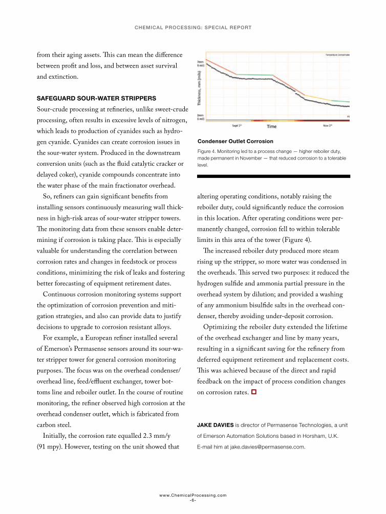
Initially, the corrosion rate equalled 2.3 mm/y (91 mpy). However, testing on the unit showed that
altering operating conditions, notably raising the reboiler duty, could significantly reduce the corrosion in this location. After operating conditions were per-manently changed, corrosion fell to within tolerable limits in this area of the tower (Figure 4).
The increased reboiler duty produced more steam rising up the stripper, so more water was condensed in the overheads. This served two purposes: it reduced the hydrogen sulfide and ammonia partial pressure in the overhead system by dilution; and provided a washing of any ammonium bisulfide salts in the overhead con-denser, thereby avoiding under-deposit corrosion.
Optimizing the reboiler duty extended the lifetime of the overhead exchanger and line by many years, resulting in a significant saving for the refinery from deferred equipment retirement and replacement costs. This was achieved because of the direct and rapid feedback on the impact of process condition changes on corrosion rates.
JAKE DAVIES is director of Permasense Technologies, a unit
of Emerson Automation Solutions based in Horsham, U.K.
E-mail him at [email protected].
Condenser Outlet Corrosion
Figure 4. Monitoring led to a process change — higher reboiler duty, made permanent in November — that reduced corrosion to a tolerable level.
www.ChemicalProcessing.com-6-
CHEMICAL PROCESSING: SPECIAL REPORT
Successfully Combat Pipeline CorrosionA comprehensive maintenance strategy can enhance efficiency and safety.
By Andy Santalucia, Clean Harbors
Pipelines at processing facilities impact overall plant performance and profitability. Their efficiency contributes to greater productivity, lower energy costs and better safety. However, ensuring highest pipeline efficiency demands periodic inspections, cleaning and rehabilitation.
Corrosion can decrease efficiency — increasing the energy required to move product, operating tem-peratures (which may affect chemical reactions) and pressure. Reducing deposit accumulations, friction and corrosion, along with engineering design enhance-ments, chemical treatments and internal coatings, can accelerate flow rates in pipelines.
Corrosion also can undermine the integrity of pipelines, causing safety risks and leading to expen-sive replacements.
A line’s corrosion rate depends upon what it’s han-dling. Some pipelines, such as those for water, need frequent monitoring and maintenance while others, designed to carry specific chemicals, only require periodic monitoring for impurities that could affect line integrity.
Corrosion significantly contributes to pipeline inef-ficiencies, especially in water supply and waste lines. Some chemicals also pose substantial corrosion risks. For instance, sulfuric acid at 80–90% concentration isn’t corrosive but should its concentration drop to below 50%, say, because of an upset, the acid becomes quite corrosive. Methanol and jet fuel lines that oper-ate intermittently can suffer corrosion and internal metal loss; the fluid itself isn’t corrosive but subsequent
introduction of water, hydrogen sulfide or other chem-icals causes reactions with the steel.
Plant staff should look particularly for corrosion in lines:• handling feedwater or wastewater;• in which the concentration of a chemical has gone
down, either inadvertently or because of deliber-ate dilution;
• where the chemical has become contaminated;• carrying steel-reactive chemicals; and• not in constant use.• Typical indicators of corrosion include:• greater turbulence (friction factor);• higher pump energy consumption;• increased pressure drop;• decreased flow rate; and• elevated product temperature.
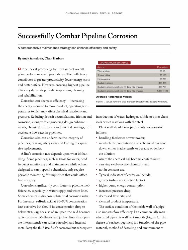
The surface condition of the inside wall of a pipe also impacts flow efficiency. In a commercially man-ufactured pipe this wall isn’t smooth (Figure 1). The degree of surface roughness is a function of the pipe material, method of descaling and environment to
Surface Microinches
Window glass 35-50
Copper tubing 100-150
Epoxy coating 150-250
Steel pipe, pickled 300-400
Steel pipe, pickled, weathered 30 days, wire brushed 600-700
Steel pipe, pickled, weathered 90 days, wire brushed 1,000-1,400
AVERAGE ROUGHNESS VALUES
Average Roughness Values
Figure 1. Values for steel pipe increase substantially as pipe weathers.
www.ChemicalProcessing.com-7-
CHEMICAL PROCESSING: SPECIAL REPORT
which it has been exposed. In turbulent flow the sur-face roughness affects the friction factor and, thus, the pressure gradient in the pipe.
Over time, scale and deposits may form, impeding flow — reducing throughput, stressing equipment and increasing the probability of unscheduled downtime.
For a simple, short, straight section of a 12-in.-di-ameter (9,300-mm) water line, “The Pipeline Pigging Handbook,” 3rd edition, notes: “if the inside diam-eter is reduced by 5% (15 mm) by a smooth deposit, the loss of throughput at a given pressure would be over 10%. To bring the throughput back to its orig-inal level would require pressure to be increased by almost 30%. However, if as is more likely, the deposit was uneven, the resulting turbulent flow may cause an effective reduction of 15%. In this case, through-put could be reduced by some 35%, while the pressure to overcome these losses would need to be increased by more than 140%.”
PROBLEM DETECTION
Routine inline inspections provide a good sense of the condition and projected life of the line. They can identify potential problems, including safety or flu-id-contamination issues, and may give early enough warning so managers can plan repairs during a sched-uled turnaround.
Technologies to assess line condition and evaluate welds include visual, X-ray, magnetic flux leakage (MFL) and ultrasonics. The most common are caliper or geometric inspection, MFL and ultrasonic.
Caliper or geometric tools effectively detect and size deformations that can affect pipeline integrity or impede the passage of other inspection (or clean-ing) tools.
MFL and ultrasonic “smart pigs” can detect anom-alies and metal loss over the 360° circumference of the pipeline wall, differentiate between internal and external location, and produce longitudinal distance measurements that accurately pinpoint anomalies.
They come with analysis software that provides hard copy reports with pipeline defect definition data as well as joint-count and anomaly tables. These detailed reports highlight out-of-specification findings based on 360° scans at a rate of up to 8,000 samples/second with resolution of ¼ inch. The reports include A, B and C scan data, as well as 3-D color-coded represen-tations of wall thickness.
In selecting inspection technology, a plant should consider factors such as cost, pipeline bend radius, length of tools, fluid medium, pressure ratings of the pipeline and wall thickness. MFL tools are less expen-sive than ultrasonic ones but typically are longer (up to 8-ft long for an 8-in. line) and may require higher pressures and flow rates. Ultrasonic tools generally are smaller than MFL ones and can be bi-directional but are more expensive and must be run in water or another suitable fluid.
Effective inspections examine both the inside and outside of the pipe wall, identify corrosion, and record denting, pitting, ovality and swelling.
Inspections also provide a baseline for future eval-uations and to develop more precise estimates of corrosion rate and pipeline life expectancy. Some com-panies with regular pipeline maintenance programs install permanent pigging launching and receiving facilities to make it easier, less costly and more efficient to conduct frequent inspections.
MAINTENANCE PROGRAM
Outside of capital investments, effective pipeline maintenance is the only way to significantly impact performance. Even incremental improvements may deliver substantial returns.
An operating company should establish a pipeline maintenance program for every site. This involves first evaluating each pipeline to gauge current throughput efficiency, performing thorough pipeline maintenance, and then rechecking efficiency to evaluate the overall upgrade. Regular pipeline flow studies over time can
www.ChemicalProcessing.com-8-
CHEMICAL PROCESSING: SPECIAL REPORT

track declines in product flow efficiency — and prompt pigging, flow sweeping, corrosion inhibition and other maintenance activities when the efficiency drop becomes significant.
Pipeline flow efficiency test. It’s relatively easy to esti-mate what the expected pressure drop of a particular pipeline should be by analyzing original design draw-ings and calculations. The difference between original design and actual pressure drop indicates lost effi-ciency due to buildup of scale, sediment or corrosion on the pipe wall, and enables estimating potential energy savings and throughput increases to justify the cost of a cleaning program.
Recently, a refinery estimated solids’ buildup in a 22-in. raw water line was causing an additional pres-sure drop of 7.5 psi. It reckoned cleaning the line would increase flow to 3,400 gpm from 2,800 gpm; this would allow for single pump operation most of the year, saving $100,000/year.
A variety of details are helpful for assessing the poten-tial improvement: the piping’s manufacturer, age, outer and inner diameters, wall thickness, and whether it’s pig-gable and there’s a history of corrosion or leaks; the fluid’s composition, specific gravity, temperature, pressure, flow rate and velocity; the upstream and downstream pumps’ suction and discharge pressures; and the type of efficiency problem (low flow, solids, sludge, scale, etc.) if known.
Analyses for liquid pipelines include flow rate, pressure drop, velocity, pumping power and reduction in diameter. Frictional pressure drop (ΔP) is the pressure difference between the beginning measurement point (P1) and the ending measurement point (P2) over a given length (L) of pipe. Pressure drops should take into account equivalent lengths, elbows, valves, fittings and elevation changes.
At Clean Harbors, we use the following rules of thumb and equation: maximum liquid velocity shouldn’t exceed 15 ft/sec (4.6 m/sec); minimum
velocity shouldn’t drop below 3 ft/sec (0.9 m/sec); and flow is determined via:
ΔP = (11.5×10 -6) fLQ2SG/d5
where ΔP is in psi; f is the Moody friction factor, dimensionless; L is in ft; Q is liquid flow rate, bbl/day; SG is the specific gravity of the liquid relative to water; and d is pipe inner diameter, inches.
The Moody diagram (Figure 2) plots ƒ as a function of Reynolds number, NRe, and relative roughness, i.e., absolute roughness, ε, divided by pipe diameter, D. At NRe less than 2,100, laminar flow prevails and f only is a function of NRe while at NRe exceeding 2,100 (flow in the transition and turbulent regimes) relative roughness also has an impact on f, so it’s necessary to determine ε. Deterioration over time due to corrosion, erosion and scale buildup considerably increases the roughness factor, thereby reducing the pipe’s effective diameter and requiring an adjustment in f.
Moody Diagram
Figure 2. Values for steel pipe increase substantially as pipe weathers.
MOODY DIAGRAM
ε, (ft) ε, (mm)Riveted steel 0.003-0.03 0.9-9.0Concrete 0.001-0.01 0.3-3.0Cast iron 0.00085 0.25Galvanized iron 0.0005 0.15Commercial steel or wrought iron 0.00015 0.046Drawn tubing 0.000005 0.0015
www.ChemicalProcessing.com-9-
CHEMICAL PROCESSING: SPECIAL REPORT
OPTIMAL PERFORMANCE
A plant can take several steps to maintain flow efficiency:
Cleaning. A number of technologies can increase efficiency and safety, and extend pipeline life. These range from closed-loop pigging to onstream mechani-cal, chemical or ultrasonic cleaning.
Selecting the most effective cleaning strategy requires some knowledge of the scale or residue that may be in the line. Examining a sample of the deposits will allow for a better determination of the types of pigs needed, and chemical cleaning agent(s), e.g., detergents, surfactants or acids, best suited for the pipeline. This also will aid in the planning for collection and disposal of effluents from cleaning. In some cases, chemical circulation or vapor phase cleaning may be the most effective cleaning option.
Internal pipeline rehabilitation and coating. Following inspection and cleaning, coating the inner pipeline surface often provides the most effective approach to increasing pipeline efficiency and durability. This effec-tively isolates the metal surface from water, hydrogen sulfide and other contaminants. An epoxy coating eliminates corrosion because there’s no contact between the pipe wall and the material being transported. The coating increases throughput and reduces maintenance and inhibitor costs at a fraction of the cost of pipeline replacement. It can rehabilitate long sections of existing pipelines and extend the life of new ones.
The in-situ epoxy coating process only requires access at the ends of the pipeline segment being
serviced. The particular epoxy coating chosen depends upon the material being transported. Two specially designed coating pigs, operated at a closely controlled driving pressure and velocity, apply a series of thin coats of the specified epoxy over sev-eral passes. The process provides a uniform, smooth, homogeneous coating throughout the pipeline, including all field joints (welds) and bends. The coating’s surface roughness doesn’t increase over time, unlike that of an uncoated surface.
Measuring the improvement. The increase in pipeline flow efficiency should be evident, and can be as much as 15–30% after cleaning and especially after internal coating. The percentage improvement as it relates to fluid throughput can be determined via:
% = (ΔPafter cleaning - ΔPbefore cleaning) × 100(Note that ΔP is proportional to the square of flow
rate.)
THE BOTTOM LINE
With fixed throughput and upstream pressure, a well-maintained pipeline section can achieve a higher downstream pressure by decreasing the surface rough-ness of the pipe caused by corrosion. A higher suction pressure (and, thus, a lower required head or specific energy) will result in a lower energy cost for pumping. The amount of savings depends upon the degree of the roughness improvement; an internal coating provides optimum results.
Keeping a pipeline in top condition also enables more efficient product movement, and boosts safety and quality.
A higher suction pressure will result in a lower energy cost for pumping.
www.ChemicalProcessing.com-10-
CHEMICAL PROCESSING: SPECIAL REPORT

Efforts Pin Down CorrosionDiverse efforts seek insights for understanding and combating the pervasive problem.
By Seán Ottewell, Editor at Large
Corrosion eats up 3–4% of global gross domestic product each year, according to a 2016 study by NACE International. That translates to an annual cost of about $2.5 trillion, says the Houston-based organiza-tion that focuses on corrosion prevention and control. However, corrosion remains an elusive as well as an expensive problem to pin down.
“Chemically we understand what corrosion is — but unfortunately it doesn’t occur uniformly at all. If it did, it would be easy enough to predict the rate of corro-sion. What we need is well-controlled corrosion films to protect metals. It’s understanding why corrosion accelerates suddenly and takes place in a particular location that is crucial here,” explains Philip Withers, a professor of materials at the Royce Institute, Univer-sity of Manchester, U.K.
“What is less well understood are specific features of corrosion. For example, corrosion at the atomistic level is a non-deterministic, stochastic process. So, the corrosion rate on a piece of equipment that is being used in exactly the same way from day to day will vary from day to day. Engineers don’t understand this way of thinking,” adds Stuart Lyon, AkzoNobel professor of corrosion control at the university.
In an effort to tackle this problem, last July BP, London, teamed up with the University of Manchester in a £5-million (≈$7-million) collaborative project. The funding is coming jointly from BP and the U.K.’s Engineering and Physical Sciences Research Council (EPSRC).
The project will bring together top researchers from the company, Imperial College London and the
University of Cambridge — many of whom already work together on corrosion research through the six-year-old BP International Centre for Advanced Materials (BP-ICAM) at Manchester University — along with additional experts from the University of Leeds and University of Edinburgh.
This project stems from an earlier BP-ICAM effort which studied the fundamental processes that initi-ate corrosion.
“Manchester, Cambridge and Imperial have been working together for more than five years with BP looking at a range of advanced materials problems. But to solve these, we needed to bring in new skills. So, we recruited expertise from Leeds on tribocor-rosion [material degradation due to the combined effect of wear and corrosion] and expertise from Edin-burgh on how high pressure can affect the behavior of interfaces,” says Withers, who serves as principal investigator on the new project.
New Corrosion Project
Figure 1. Effort brings together expertise from several U.K. universities as well as an oil company. Source: University of Manchester.
www.ChemicalProcessing.com-11-
CHEMICAL PROCESSING: SPECIAL REPORT
By combining this expertise with different skills in modelling and imaging as well as performing exper-iments under real-life conditions, the team hopes to answer three fundamental questions: What happens at the start of corrosion? How does it then propagate? And what occurs in tribocorrosion? Some of the basic understanding gained should enable improving current materials; the team will focus particularly on develop-ing better coatings and inhibitors as well as wear-side lubricants and additives that can be used with them to extend equipment life (Figure 1).
By applying synchrotron radiation, among other techniques, the researchers hope to understand the very early stages of oxidation. Such radiation pene-trates the surface of corrosion films and helps to show the importance of material stresses and densities on how protective layers break up in localized areas.
“Imaging is very important and we are now able to cheat the fundamental limits of the accuracy to get amazing resolutions. Fifteen-to-twenty years ago, for example, 20–30 microns was high resolution with X-ray imaging. Today, we are [at] the 50-nm scale. The great thing about using X-rays is that you can look through materials, so you get to see pits and other fea-tures and understand them at the sub-micron scale,” Withers explains.
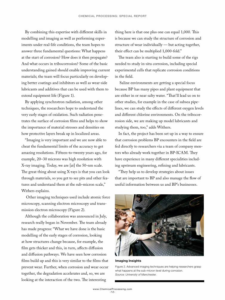
Other imaging techniques used include atomic force microscopy, scanning electron microscopy and trans-mission electron microscopy (Figure 2).
Although the collaboration was announced in July, research really began in November. The team already has made progress: “What we have done is the basic modelling of the early stages of corrosion, looking at how structures change because, for example, the film gets thicker and this, in turn, affects diffusion and diffusion pathways. We have seen how corrosion films build up and this is very similar to the films that prevent wear. Further, when corrosion and wear occur together, the degradation accelerates and, so, we are looking at the interaction of the two. The interesting
thing here is that one plus one can equal 1,000. This is because we can study the structure of corrosion and structure of wear individually — but acting together, their effect can be multiplied 1,000-fold.”
The team also is starting to build some of the rigs needed to study in-situ corrosion, including special experimental cells that replicate corrosion conditions in the field.
Saline environments are getting a special focus because BP has many pipes and plant equipment that are either in or near salty water. “That’ll lead us on to other studies, for example in the case of subsea pipe-lines, we can study the effects of different oxygen levels and different chlorine environments. On the tribocor-rosion side, we are making up model lubricants and studying them, too,” adds Withers.
In fact, the project has been set up in a way to ensure that corrosion problems BP encounters in the field are fed directly to researchers via a team of company men-tors who already work together in BP-ICAM. They have experience in many different specialities includ-ing upstream engineering, refining and lubricants.
“They help us to develop strategies about issues that are important to BP and also manage the flow of useful information between us and BP’s businesses.
Imaging Insights
Figure 2. Advanced imaging techniques are helping researchers grasp what happens at the sub-micron level during corrosion. Source: University of Manchester.
www.ChemicalProcessing.com-12-
CHEMICAL PROCESSING: SPECIAL REPORT
These mentors are really important because they push us to look not just at simple corrosion situations but also more-complex industrial-type situations. We also have a project manager from BP with lots of goals for us to achieve, for example plotting the gradual move from in-situ investigations of simple species to more demanding situations,” Withers notes.
This reflects the nature of the EPSRC funding, too, which came via the first round of a new initiative called prosperity partnerships. These are aimed spe-cifically at bringing together industrial and academic expertise to solve industry-critical problems.
COATINGS CONCERNS
AkzoNobel, Amsterdam, has been collaborating with the University of Manchester for more than 30 years. Not part of the BP-ICAM initiative, the company focuses more on the interaction between corrosion and coatings, and broader materials sciences issues.
In 2009, the company decided that corrosion pro-tection was such an important area both for itself and its customers that it set up a specialist community of practice (COP). “My job is to manage the knowledge in this area — to highlight what we know and what we don’t know,” says Simon Gibbon, AkzoNobel COP leader in the field of corrosion protection at the university.
One of the outcomes of this decision was the 2012 launch of a more-focused collaboration to look at how corrosion interacts with existing coatings and then to use this knowledge both to improve their function and to develop new, improved coatings.
In the intervening years, the team has nailed a couple of things — particularly some hypotheses that were based on gut feeling, according to Lyon. “We’ve proved some and disproved others.”
For example, he says it’s quite easy to imagine that coating adhesion is really important and controls corrosion processes. Yet, it’s easy to find additives that increase adhesion but,in practice, actually reduce
performance as well as some coating systems that show poor adhesion but provide superb performance, he cautions.
“So, this hypothesis is incorrect — sure the paint has to stick sufficiently to limit mechanical damage but beyond this there is no further benefit (and may be detriment) in corrosion protection by further increas-ing adhesion.”
Another idea is that damage gradually builds up in coatings during service until flaws join to create an easy pathway from the environment to the substrate. Because the polymers used in most paint systems are crosslinked networks, it’s been assumed that poorly crosslinked areas are most susceptible to water uptake and damage.
“However, for some coatings we have shown the opposite — more highly crosslinked parts of the poly-mer absorb more water. This counter-intuitive result was only obtained because, using our advanced ana-lytical tools, we can probe the molecular composition of polymers at the nanoscale. So, this hypothesis may be correct but for the wrong reason. It’s important because you cannot accurately and reliably design a paint system based on incorrect hypotheses.”
One of the key chemical industry challenges Gibbon is tackling is corrosion under insulation (CUI). He notes: “This is particularly a problem caused by retro-fits and if new builds aren’t done to standard. But how do you detect it?”
The corrosion might occur at a location that’s inaccessible or covered with a hard-to-safely-remove insulation layer. He knows of chemical companies that are fabricating entire buildings around very sen-sitive plant items to prevent exposure to water, drips from other pipes, joints, etc., that could lead to such corrosion. Another issue is humidity, particularly in cryogenic or other systems where condensation occurs, for example during plant downtime.
“So, it’s a complex challenge. We are working with experts in sensing technologies at Manchester to identify clever ways to incorporate intelligence into
www.ChemicalProcessing.com-13-
CHEMICAL PROCESSING: SPECIAL REPORT
coatings so that local damage can be narrowed down to a limited area on the plant.”
“One way to prevent CUI, especially for new builds, is to ensure that the coatings are applied properly and the equipment they are used on is installed properly. It’s also important that the underlying metal meets the design spec. We’ve had incidents of coating failures which occurred because the metal manufacturer changed its process slightly and this, in turn, created surface issues,” adds Gibbon (Figure 3).
Lyon believes this message is getting through to the chemical industry, at least its more-enlightened companies: “The value added is definitely being appreciated and we are working together to create extra value for both Azko and the asset owners.”
However, most operating companies have dis-pensed within-house corrosion engineers and metallurgists, he points out, leading to a loss of knowledge that can prompt problems. For instance, he cites a company whose bronze shell-and-tube condenser failed after 22 years. A contractor suggested lining the tubes to plug the leaks. “However, what seemed like a good idea massively speeded up corrosion due to the increased f low rate such that the failure occurred again after just 18 months.”
He mentions a corn syrup producer in the U.S. as another cautionary example. To save on the costs of potable water being used in manufacturing, it switched to its own well water. “It sounds like a very logical decision by the plant manager but the potable water contained 100ppm of chloride ions while the well water contained 500ppm. The plant suffered a $3–4-million failure because of the resulting local-ized (pitting)corrosion problems,” he explains.
False economies also afflict painting. It’s common for a plant to opt for the cheapest quote when paying perhaps 20% more for professional applicators could
double a coating’s life, stresses Lyon. This is one of the reasons that AkzoNobel has pioneered an industrial painting qualification with the Institute of Corrosion, Northampton, U.K.
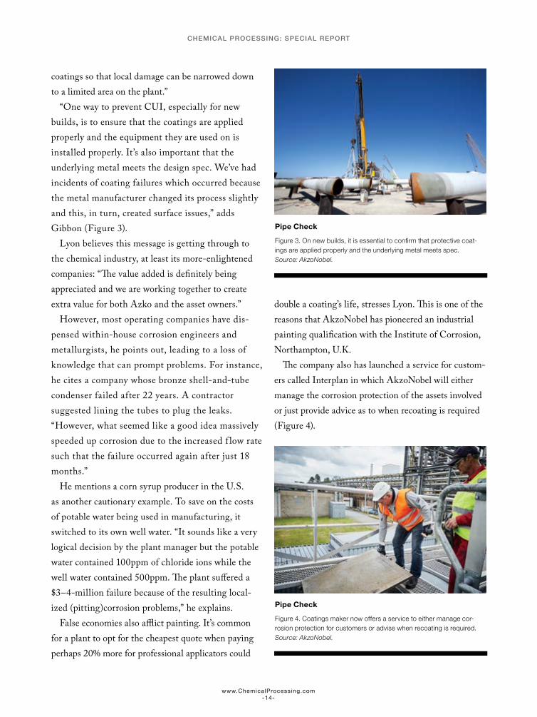
The company also has launched a service for custom-ers called Interplan in which AkzoNobel will either manage the corrosion protection of the assets involved or just provide advice as to when recoating is required (Figure 4).
Pipe Check
Figure 4. Coatings maker now offers a service to either manage cor-rosion protection for customers or advise when recoating is required. Source: AkzoNobel.
Pipe Check
Figure 3. On new builds, it is essential to confirm that protective coat-ings are applied properly and the underlying metal meets spec. Source: AkzoNobel.
www.ChemicalProcessing.com-14-
CHEMICAL PROCESSING: SPECIAL REPORT

“There are few corrosion issues on chemical plants that are not user-related,” cautions Gibbon.
INTERNAL RESOURCES
Unlike most chemical makers, BASF, Ludwigshafen, Germany, boasts an in-house materials engineering unit to support production processes. It covers all aspects of materials engineering connected with chem-istry, including corrosion issues, and uses a range of non-destructive testing technologies.
However, the company goes outside when necessary. “In the case of exceptional and very specific problems, we cooperate with external partners such as universi-ties and research facilities,” notes a spokeswoman.
One such partner is the Materials Technology Institute, St. Louis, Mo., where BASF is working with other chemical companies including Air Prod-ucts, Sabic, DuPont, Shell, Air Liquide and Chevron
on a range of research initiatives. One focuses on using software for thermodynamic modeling of cor-rosion and training engineers so they can predict the performance of alloys in corrosive environments and to improve the design of corrosion experiments. Another focuses on developing non-invasive monitor-ing techniques that can identify corrosion issues that lead to the deterioration of refractory linings.
BASF also works with the German Society for Corrosion Protection, Frankfurt, which acts as an interdisciplinary federation to bring together corrosion experts from industry and academia — with the aim of developing better tools to understand and deal with corrosion and its consequences.
“The benefit of these collaborations is that members affected with the same damage mechanisms work jointly together on mitigation approaches,” says the spokeswoman.
“There are few corrosion issues on chemical plants that are not user-related”
www.ChemicalProcessing.com-15-
CHEMICAL PROCESSING: SPECIAL REPORT