Embed Size (px)
Citation preview

ARGUS
1ARGUS 26
ARGUS 26Manual

ARGUS
2 ARGUS 26
by intec GmbH, D-58507 Lüdenscheid, Germany,2003
Alle Rechte, auch der Übersetzung, vorberhalten. Kein Teildes Werkes darf in irgendeiner Form (Druck, Fotokopie,Mikrofilm oder einem anderen Verfahren) ohne schriftlicheGenehmigung reproduziert, vervielfältigt oder verbreitetwerden.-
All rights are reserved. No portion of this document may bereproduced, duplicated or distributed in any form (print,copies, microfilm or on any other media) without intec’swritten permission.
Version: 4.0

Inhalt
3ARGUS 26
1 Introduction ......................................................... 7
2 Safety Instructions ........................................... 11
3 Technical data ................................................... 12
4 Operation ........................................................... 134.1 Charging the accumulators ............................. 17
5 Menu Hierarchy ................................................. 19
6 Automatic Access Test .................................... 31
7 Access menu .................................................... 417.1 Open the Access menu .................................... 417.2 Selection of the physical access .................... 42
8 Select the Access Mode ................................... 448.1 Operation on a BRI or PRI access .................. 44
8.1.1 TE-Simulation mode .................................. 448.1.2 NT-Simulation mode P-P or P-MP ............. 458.1.3 Permanent circuit ....................................... 468.1.4 BRI/PRI Monitor ......................................... 548.1.5 BRI / PRI Recorder .................................... 58
8.2 Operation on a U-interface access (optional) 678.2.1 TE simulation mode ................................... 678.2.2 Permanent circuit ....................................... 67
8.3 Operation on a POTS (analog) access ........... 688.3.1 POTS terminal ........................................... 688.3.2 POTS monitor ............................................ 68
9 Operation on an X.21 access (optional) ......... 709.1 BERT start ......................................................... 71
10 Single Tests ...................................................... 7410.1 Supplementary Services Test ......................... 75
10.1.1 Supplementary Service Test - 1TR6 ...... 7510.1.2 Suppl.service interrogation in DSS1 ........ 7710.1.2.1 Error messages .................................... 86
10.2 Service check .................................................... 8610.3 Bit error test ...................................................... 92
10.3.1 BERT startwait ......................................... 9410.3.2 Bert wait ................................................. 10010.3.3 B-channel loop ....................................... 101
10.4 X.31 Test .......................................................... 10310.4.1 Automatic X.31-Test .............................. 10310.4.1.1 D-Channel: ........................................ 10410.4.1.2 B-Channel - Case A ............................ 10610.4.1.3 B-Channel - Case B ............................ 10610.4.2 Manual X.31 Test .................................. 107

Inhalt
4 ARGUS 26
10.4.2.1 D-Channel: ........................................ 10710.4.2.2 B-Channel - Case A ........................... 10910.4.2.3 B-Channel - Case B ........................... 110
10.5 CF Interrogation ............................................. 11110.6 CF Activation .................................................. 11410.7 MSN Interrogation .......................................... 11610.8 Traffic generator ............................................. 11710.9 Time measuring .............................................. 121
10.9.1 Connection setup time .......................... 12210.9.2 B-channel delay .................................... 12310.9.3 Interchannel delay ................................. 124
11 Connection ..................................................... 12511.1 Setting up an ISDN connection ..................... 12511.2 Setting up an ISDN connection ..................... 13511.3 Operation on a POTS (analog) access ......... 137
12 Test Manager .................................................. 14012.1 Simultaneously Starting Several Tests ........ 141
12.1.1 Switching Between Tests ...................... 14712.1.2 Cancel all .............................................. 147
13 Automatic Test ............................................... 14813.1 Starting the Automatic Test .......................... 15113.2 Display Results .............................................. 15413.3 Test results – sending to a PC ...................... 15613.4 Printing the test results (optional) ................ 15713.5 Deleting test results ....................................... 158
14 Voltage and level measurement ................... 15914.1 Level measuring on a BRI access ................ 15914.2 Voltage measurement on a U-interface ........ 16214.3 Voltage measurement on a POTS access .... 163
15 L1 Status ......................................................... 16415.1 The L1 status of a BRI access ...................... 16415.2 The L1 status of a PRI access ....................... 165
16 Configuration .................................................. 16816.1 Trace mode ..................................................... 16916.2 Configuration: ISDN ....................................... 171
16.2.1 Layer 1 permanent ................................ 17116.2.2 Select the D-channel protocol ............... 17316.2.3 Alerting mode ........................................ 17416.2.4 Clock mode ........................................... 17516.2.5 BRI termination ..................................... 17616.2.6 PRI termination ..................................... 17716.2.7 PRI haul mode ...................................... 17816.2.8 Setting the Sa5 Bits ............................... 179

Inhalt
5ARGUS 26
16.2.9 Setting the Sa6 Bits ............................... 18016.2.10 Setting the A-Bit ................................... 18216.2.11 CRC4 mode ......................................... 18316.2.12 Call parameter ..................................... 18416.2.13 Services ............................................... 18616.2.14 Call Acceptance ................................... 18816.2.15 Voice coding ........................................ 18916.2.16 DTMF / Keypad ................................... 190
16.3 Configuration: BERT ...................................... 19116.3.1 BERT - duration ..................................... 19116.3.2 BERT - Setting the Error level ............... 19316.3.3 HRX value ............................................. 19416.3.4 Selecting the BERT bit pattern .............. 195
16.4 Configuration: POTS ...................................... 19716.4.1 POTS dial mode .................................... 19716.4.2 POTS CLIP ............................................ 19816.4.3 AOC pulse ............................................. 19916.4.4 DTMF parameter ................................... 20016.4.5 FLASH time ........................................... 204
16.5 Configuration: ARGUS ................................... 20516.5.1 Selecting the menu language ................ 20516.5.2 Setting the display contrast ................... 20616.5.3 Enter date / time .................................... 20716.5.4 Printer .................................................... 20816.5.5 Baud rate ............................................... 21016.5.6 Handset ................................................. 21116.5.7 Alarm bell ............................................... 21216.5.8 Feed ...................................................... 21316.5.9 Battery type ........................................... 21416.5.10 Accu servicing ..................................... 21516.5.11 Enabling a software option .................. 217
16.6 Saving Call Numbers ...................................... 21816.7 Reset ................................................................ 220
17 Testing Features with the Keypad ................ 222
18 Connection for a PRI network ....................... 22318.1 Connector Pin Assignments on the ARGUS 22318.2 Connection to DTAG NTPM ........................... 22418.3 The ARGUS 26 as Terminal ........................... 224
19 Appendix ......................................................... 225A) Acronyms .................................................... 225B) CAUSE-Messages – DSS1 Protocol .......... 228C) CAUSE-Messages – 1TR6 Protocol ........... 230D) ARGUS Error Messages ........................... 232E) Package Contents ...................................... 235

Inhalt
6 ARGUS 26

1 Introduction
7ARGUS 26
1 Introduction
The ARGUS 26 premium ISDN combi-tester supports all ofthe functions needed when installing or maintaining BRI,2Mbit/E1, X.21, PRI and U interface accesses or POTS.
In particular, service technicians, who increasingly work onlarger, networked telephone systems and switchingsystems, will quickly find the ARGUS 26 an indispensabletool. With its rechargeable batteries and internal charger, theARGUS is exceptionally well suited for use in field service.The intuitive menu operation combines convenient cursorkeys and softkeys with a four-line backlit display.-
Besides TE/NT simulation on BRI and PRI accesses, theARGUS 26 also supports TE simulation on U interfaces(optional) and POTS as well as convenient BRI and PRI D-channel monitoring. The 16 megabytes of internal Flashmemory enables the tester to record and save themonitoring data without requiring a connection to computer.-
The Flash-ROM technology permits you to upgrade yourARGUS at any time by download software updates from aPC (free software updates are available at www.argus.info).
If you use the ARGUS on a BRI or PRI interface in an ISDNsystem whose specifications deviate from the (DIN ETS 300102) standard (e.g. some networked PBXs), you must takethese manufacturer-specific modifications into account. Insuch cases, please contact the distributor of your ISDN PBXfor assistance.
For the optional test of X.21 permanent circuits, you canconnect the ARGUS to the X.21 network via an X.21Adapter.-
As an option, a V5.x monitor is available for the ARGUS 26:This monitor can be used to record the V5.1 or V5.2protocol, which can then be decoded in detail with theWINanalyse software. The ARGUS Functions - Overview:
Protocol Recognition and B-Channel Test for ISDNAccesses

1 Introduction
8 ARGUS 26
After you select the operation mode, the ARGUS willautomatically determine the protocol supported by theaccess under test and will then test the availability of the B-channels.
Telephone connections
Can a telephone call be placed from this access to everyother number and/or can this access receive a call?
Service Tests
Does the tested access support connections with the mostimportant services, such as, ISDN telephone service, Group4 - Facsimile or data transmission at 64 kbit/s etc.? Additionally, 3 user-specific services can be saved in theARGUS and tested on the access under test.
Bit error tests (BERT)
Performs a BERT in an extended call to itself via a loopboxor in end-to-end operation. The ARGUS will, if needed,handle the loopbox function itself. The integrated MegaBERT extends the bit error test to abandwidth of a full 2 Mbit/s. Any distribution of time slots (nx 64 kBit/s ) may be used.
Supplementary Services
The ARGUS automatically tests the supplementary servicesmade available by the exchange.
Leased Line Tests – tests permanent circuits with BERTand speech
NT simulation of a BRI or a PRI access
D-channel monitoring on a Basic Rate Interface and ona Primary Rate Interface
All of the D-channel signals are captured and passed to theserial interface. When passively monitoring, the ARGUSdoes not affect Layer 1.
POTS (analog) Functionality
Does the analog access support call number transfer?The ARGUS will display the charges, if the access supports

1 Introduction
9ARGUS 26
this feature.
Monitoring an analog line (passive listening-in)
CF Interrogation
The ARGUS will check, whether a call diversion has beensetup on the access under test. The ARGUS can setup orclear down call diversions in the exchange.
MSN interrogation (only on a BRI access)
On a P-MP access using the DSS1 protocol, the ARGUS willdetermine the MSNs of the access under test.
X.21 test (optional)The ARGUS will perform a bit error test on the X.21 accessin accordance with the ITU guidelines G.821 and G.826.
The Access Acceptance Report
When the ARGUS is linked to a PC via the serial interface, itis, as an example, possible - with the aid of WINplus - tocreate and print a comprehensive test report on the PC. Testing Features with the Keypad
Supports manual tests in the so-called keypad mode. If thenetwork supports this feature, the user can send a commandsequence and can then test service features in a dialog.
Should you have any further questions, please contact us:
intec GmbHRahmedestr. 90
D-58507 LüdenscheidTel.: +49 (0) 2351 / 9070-0
Fax: +49 (0) 2351 / 9070-70

1 Introduction
10 ARGUS 26

2 Safety Instructions
11ARGUS 26
2 Safety Instructions
The ARGUS may only be used with the includedaccessories. Usage of other accessories may lead toerroneous measure-ments and may even cause damage tothe ARGUS and the connected installation.
The ARGUS is only to be used in accordance with theinstructions in this documentation. Any other usage mayresult in bodily injury and destruction of the ARGUS.
• To prevent electrical shocks or damage to the ARGUS-, do not connect it to lines with voltages in excess of 100V!
• Never attempt a measurement with the case open!
• The ARGUS is not watertight. Protect the ARGUS from exposure to water!
• Before replacing the battery(see page 15 Replacing the accumulators), disconnect all the test leads and switch the ARGUS off. Make certain that the polarity is correct when
connecting the batteries!

3 Technical data
12 ARGUS 26
3 Technical data
Dimensions / WeightHeight 229 mmWidth 72 mmDepth 35 mmWeight 350 g (withoutbatteries and protectivecase)Keypad21 Keys
LCD display LCD display withswitchablebackground lighting4 lines with 16 characters
Memory EEPROM Non-volatilememory: 2048BytesFlash programmemory: 1 Mbyte
S-RAM: 256 Kbytes +128 Kbytes Data memory: 16 Mbyte
(Flash)
Inputs / Outputs
1 RJ-45 for BRI, PRI,U-interface (optional) orPOTS
1 jack for an externalpower supply
1 RJ45 forconnecting to an X.21network or a PC
Temperature RangesAmbient-temperature: 0 °C to +50 °C
Operatingtemperature: -5 °C to +55 °C
PowerSupply3 NiMH accumulatorsor9 V, plug-in powersupplyor
BRI feed

4 Operation
13ARGUS 26
4 Operation
Power-Key:
- To switch the ARGUS ON/OFF- To start up again after a power down- Switches on the display backlighting (to
save power, in accu / battery mode thebacklighting is switched OFFautomatically after 5sec.)
- To switch the ARGUS OFF (must be pressed somewhat longer) if it is switched off when the power supply is connected the accumulators will be recharged(see Chapter 4.1 Charging theaccumulators )
Confirmation key:
- Select menu or continue
Receiver inset
LEDs
Softkeys
Menu controlConfirmation key
Layer 1 measurement
Pickup / Hang up Calling
Power
Microphone
Fastener forshoulder strap
Numerical keypad
LCD display4x16 characters

4 Operation
14 ARGUS 26
Connectors on the end:
9 V-
Connection for the external power supply. When thepower supply is plugged into this connector, therechargeable batteries will be disconnected.-
Menu control:
- Open the menu list- Scroll through lists- Select a menu- Select a function in an open menu
Telephony (pickup and hang up)- Simplified overlap signalling: Press the telephone key twice. Layer 1 Measurement:
start the Layer 1 measurement(Level/Voltage)
Number Pad:
- Entry of the digits 0....9 and of the special characters *, # (e.g. the call
number or a numerical entry in a function)-- Direct function call (see page 39 Using the numeric keys tostart a function:)
Softkeys:
The function of the 3 softkeys varies withthe situation. The current function of eachsoftkey is shown in the highlighted fourthline of the display.

4 Operation
15ARGUS 26
Line
Connection for BRI lines (TE simulation or monitoring)Connection for a BRI terminal (NT simulation)Connection for a PRI terminal (NT simulation)Connection for a POTS networkConnection for a U-interface Adapter (optional)Connection for a PRI network (TE simulation or monitoring)
Connector for a headset
X.21/PC
Connection for the X.21 Adapter
Connection to a PC via a serial cable
Connection of a PC via the included USB Adapter
Replacing the accumulators
The battery compartment for the three accumulators(rechargeable batteries) is located on the back of the case.Unscrew the screws to remove the cover of the case andinsert the accumulators in accordance with the polaritymarking.
Use Golden-Power 1800 mAh NiMH accumulators. Thestate of the accumulator charge will be displayedgraphically.
A battery symbol begins to blink in the LCD display, whenthere is still approximately 15 minutes reserve. During thisperiod, it is possible that there may be audible interferenceand in rare cases even malfunctions.
Power Down
In accu/battery operation, if the ARGUS is idle for 15
Pin Assignment3/4/5/6 BRI7/8 POTSPIN assignment for a PRI see Chap.

4 Operation
16 ARGUS 26
minutes, it will automatically switch to the power-down mode(power-down). From this mode, the system can only bereactivated by pressing the Power-Key. In the power-down mode, the accumulators will last severalyears. Therefore, this mode serves as effective protectionagainst discharging the rechargeable batteries-.
Naturally, when the loopback function is active on theARGUS or it is in Trace mode, the ARGUS will not switch topower-down mode.
As an alternative, it is possible to operate the ARGUS usingthe included power supply.- When the power supply isconnected, the accumulators are automaticallydisconnected.
The ARGUS can also be powered from the BRI line. In this case, it does not need accumulators or the plug-inpower supply.
Whenever the ARGUS is powered from the plug-in powersupply or the BRI line, the power-down mode is reasonablyenough not active.
Regardless of the type of supply used, youshould always operate the ARGUS withaccumulators installed. This will ensure theuninterrupted operation of the real-time clock.

4 Operation
17ARGUS 26
4.1 Charging the accumulators
The accumulators will begin charging when:• the ARGUS is switched off• the rechargeable batteries are inserted• the plug-in power supply is plugged in• the accumulator voltage is less than 3.90 volts
The following is shown while the device is charging: "Chargeaccu“ with the current accumulator voltage displayed below.The Line Power LED will flash. To return to the normaloperational state, press on “ABORT”.
If you press and hold the ON key depressed, the ARGUScan be switched off entirely.
See "Chapter 16.5.10 Accu servicing “ for additionalinformationabout charging and servicing the accumulators.
• You should only use the included accumulators (Golden Power; NiMH; 1800 mAh rechargeable batteries).
• The accumulator voltage must be less than 3.90 V before the system will allow them to be recharged.- This is intended to protect the accumulators from being recharged too often.
Displayof thevoltage
Level ofcharge

4 Operation
18 ARGUS 26

5 Menu Hierarchy
19ARGUS 26
5 Menu Hierarchy
Selection of the physical access:
BRI access
PRI access
POTS (analog) interface
Automatic automatic detection of the interface used
X.21 test (optional)
The Access Mode menu opens automatically once thephysical access is selected (in the Access menu).
Operation on a BRI (S-Bus) access:
ARGUS ON
MenuAccess
MenuConfiguration
SettingOK ?
Status displayYes
MenuSingle Tests Telephony Menu
L1 Status
MenuAutomatic tests
MenuAccess Mode
No
Menu Level Measuring
MenuTest Manager
Press the Menu softkey
Access Menu
Access Mode Menu

5 Menu Hierarchy
20 ARGUS 26
TE Automatic (TE simulation automatically)
TE P-P (TE simulation point-to-point)
TE P-MP (TE simulation point-to-multipoint)
NT P-P (NT simulation point-to-point)
NT P-MP (TE simulation point-to-multipoint)
BRI Monitor The ARGUS records all D-channel signals on the BRIaccess and passes them on via the serial interface-. Layer 1 will not be affected by the monitor function.
BRI Recorder The ARGUS records all of the D-channel signals on theBRI access and saves them in the internal Flashmemory. Layer 1 will not be affected by the Recording function-.
Permanent circuitfor telephony, BERT, loopbox
Operation on a PRI access:
TE P-P (TE simulation point-to-point)
NT P-P (NT simulation point-to-point)
PRI MonitorThe ARGUS captures all of the D-channel signals on thePRI access and sends them to the connected PC via theserial interface. The bus and Layer 1 will not be affectedby the monitoring.-
PRI RecorderThe ARGUS records all of the D-channel signals of thePRI access and saves them in the internal Flashmemory. The bus and Layer 1 will not be affected by therecording.
Permanent circuitfor telephony, BERT, loopbox
Operation on a U-interface access: (optional )

5 Menu Hierarchy
21ARGUS 26
When using a U-interface Adapter, you must select BRIas the physical access in the Access menu.
TE Automatic (TE simulation automatically)
TE P-P (TE simulation point-to-point)
TE P-MP (TE simulation point-to-multipoint)
Permanent circuitfor telephony, BERT, loopbox
Operation on a POTS access:
POTS terminalThe ARGUS behaves like a POTS (analog) terminal.
POTS monitor High impedance tap without influencing the interface
Operation on an X.21 access (optional):
The Argues behaves like an X.21 terminal.(Layer 1 only)
Supplementary ServicesSupports, for 1TR6 (only on a BRI or U-interface access(optional)), automatic query of the availablesupplementary services as well as, for DSS1, manualselection of - and then automatically run -- tests of themost important supplementary services.
Service TestsTests all important services by setting up a self call-. Theprerequisite for a complete execution of this test is thattwo B-channels are available .
Bit Error TestPerforms a simple bit error test, which can be run aseither an extended call to itself, to a loopbox or “end-to-
The Single Tests

5 Menu Hierarchy
22 ARGUS 26
end“. During the test, the ARGUS shows the bit errors and theremaining measurement time in seconds. The test-results of the bit error rate test will be displayed inexponential form-. Additionally, the results will beevaluated in accordance with ITU-T G.821 and G.826.
On a permanent circuit on a PRI access, a MegaBERTcan be run with any distribution of time slots ( n x 64kBit/s).
The ARGUS will perform a bit error test on the X.21access in accordance with the ITU guidelines G.821 andG.826.
X.31 TestThe ARGUS will perform your choice of various tests onboth the D-channel and B-channel.The test results will be shown in the display.
CF Interrogation
The ARGUS checks whether call diversions are activein the exchange for the access under test (either CFU,CFNR or CFB).- The ARGUS will display the existing call-diversions (up to 10). Any call diversion setup in theexchange can be cleared with the ARGUS.
CF Activation
With the ARGUS, you can setup call diversions in theexchange.
MSN interrogation (only on a BRI access)
On a P-MP access using the DSS1 protocol, theARGUS will determine the MSNs of the access undertest.- It will display a maximum of 10 call numbers.-MSN interrogation is not supported by every exchange.Traffic generator (only on a PRI access)
The ARGUS will determine which B-channels areavailable on a -PRI access by automatically setting upconnections.
Time measuring
The ARGUS measures the setup time, the data'spropagation time and the transit time differential of thedata in two B-channels (interchannel delay).

5 Menu Hierarchy
23ARGUS 26
Connection
The call will be set up to the dialed number and theARGUS will display the number called, the charges, other information (e.g. SUB, T.o.n etc.) and the B-channel used. In the case of the service Telephony, the speechchannel will be switched onto either the integratedhandset or an optional headset.
It is possible to simultaneously and independently runmultiple tests (or connections).- The tests running in parallel are administered by theTest Manager.-
Start
The ARGUS automatically executes the test sequenceand saves the results in the internal Flash memory.
View
The ARGUS displays the saved test results.Test data to PC
The test data saved on the ARGUS will be sent to theconnected PC (when WINanalyse is running on the PC).WINanalyse presents the measured data in a clear testlog.-
Printing
With a special (optional) cable, it is also possible to printa simplified test report on a Centronics printer.-
The Test Manager
Automatic Tests

5 Menu Hierarchy
24 ARGUS 26
Delete
The ARGUS will delete the results of the tests stored inthe internal Flash memory.
Level measuring on a BRI access
Measures the signal level of the remote end on aBRI access
Feed voltage on a U interface access (optional)
Level measuring on a POTS access
The ARGUS displays the current status of the Layer 1on a BRI access and the Layer 1 parameter on a PRIaccess.
The Level Measuring
The L1 Status Menu

5 Menu Hierarchy
25ARGUS 26
Trace mode
The ARGUS passes the recorded D-channel data to theconnected PC or saves it in the internal FLASH memory.--
ISDN
Settings in ISDN:
- L1 permanent? Determines, whether Layer 1 should be permanentlyactive for a BRI connection in NT mode.
- ProtocolBesides offering automatic recognition of the D-channel protocol, the ARGUS also allows you tomanually switch between the protocols 1TR6, DSS1,CorNet-N, CorNet-T, QSIG and VN4.
- Alerting mode Setting to display numbers dialed after an incomingcall is setup on a BRI point-to-point access.
- Clock modeHere, you can select where - regardless of whether inTE or NT operating mode - the clock for the ISDN access is generated.
- BRI termination Options for the terminating resistor for the BRI accessregardless of whether in TE or NT operating mode.
- PRI terminationOptions for the terminating resistor onthe PRI access.
- SensitivityUse to set the sensitivity of a PRI access
- Setting the Sa5 bitsSet the Sa5 bits sent on a PRI access
Configuration Menu

5 Menu Hierarchy
26 ARGUS 26
- Setting the Sa6 bitsSet the Sa6 bits sent on a PRI access
- Setting the A-BitSet the A-Bit on a PRI access
- CRC4 ModeCRC4 monitoring can be switched on or off manually.-
- Call parameterThe following parameters can be set for an ISDN callgenerated on either the network-side (ARGUS in NTmode) or the user-side (ARGUS in TE mode):-
- Type of Number (TON) for the CGN or CDNelement of a SETUP signal
- Numbering plan (NP) for the CGN or CDN elementof a SETUP signal
- ServicesUp to three user-specific services (BCAP, HLC or LLC)can be entered and stored in the ARGUS for furthertests.
- Call acceptedSets, which calls the ARGUS should signal on a P-MPaccess in TE mode: only calls whose destinationaddress matches the MSN or DDI of the access undertest receive or all incoming calls-
- Voice codingSets the coding of the voice data in the B-channel. A-Law or µ-Law
- DTMF / KeypadDuring a ISDN connection, the keypad can be used tosend not only DTMF tones but also keypad elements.-
BERT
Options for the BERT
- BERT timeEnter the duration of the BERT in minutes.
- Error levelEnter the error level for the automatic Good/Bad

5 Menu Hierarchy
27ARGUS 26
evaluation of the bit error test
- HRX valueSet the HRX value (hypothetical reference connectionsee ITU-T G.821)-
- Bit patternSelect the bit pattern used in the bit error test
POTS
Settings for a POTS (analog) access
- POTS dialSets the POTS dialing mode: DTMF or pulse dialing
- POTS CLIPSet the transfer procedure used to pass the callnumber:- FSK or DTMF
- AOC pulseSpecifies the country-specific type of AOC pulse for aPOTS access:12 kHz or 16 kHz
- DTMF parameterSettings for the parameters Level, Duration andInterval of the DTMF signals generated during POTS(analog) operation.-
- FLASH timeSet the duration of the FLASH (time): 40 ms to 1second

5 Menu Hierarchy
28 ARGUS 26
ARGUS config.
Settings for the ARGUS
- Menu languageSelect the language to be used in the menus
- LCD contrastThe contrast setting for the display
- Date entryEnter the date and time. The time is kept by a built-inreal time clock.
- PrinterSetup the printer used for the print function-
- Baud rateSets the maximum baud rate (used in linking theARGUS to a PC)
- HandsetSelection of the speech channel: internal handset or external headset
- AlarmSwitches the ARGUS's alarm on or off (e.g. in theevent of an error)
- FeedSelect the supply for the ARGUS. As an example, you can switch off the option for feedfrom the BRI network.
- Battery typeSelect the type of power supply: Accumulators orbatteries
- Accu servicingCharge or discharge the accumulators in the ARGUS
- Software optionEnabling software options

5 Menu Hierarchy
29ARGUS 26
Enter numbers
Enter a maximum of ten (24 place) call numbers in thespeed dialing memory. The first number in the speed-dialing memory must bethe own call number of the access under test. This callnumber will be need later for the service check as wellas for use in all outgoing calls as your own call number(CGPN or OAD).The ARGUS expects the X.25 access number for theX.31 test to be stored in the X.31 test number memorylocation.
Reset
Resets all of the settings to the original factory (default)settings-The speed-dialing memory and the results of all of theautomatic tests will also be deleted from the internalmemory of the ARGUS.
Simplified telephoning using the telephone key. Pressing thetelephone key twice seizes the exchange line. Once the callnumber is entered the call will be setup.-
Telephony

5 Menu Hierarchy
30 ARGUS 26

6 Automatic Access Test
31ARGUS 26
6 Automatic Access Test
Using the included cable, connect the ARGUS to the accessto be tested.
Power-Key: Switch the ARGUS on.The starting window will open displaying the access andmode parameters selected last.
Displayed in the first line:The software version number: 2.6 (in the example)Country code: U (=Great Britain), E (=Spain),F=(France). . .Level of batteries' charge
Displayed in the third line:
Type of access: BRI, U-interface (optional) , PRI , POTS or X.21
Operation mode: NT = NT Simulation modeTE = TE SimulationPerman.swit.MonitorTerminal (only on a POTS (analog)
access)
Displayed in the fourth line:
The fourth line displays the current assignment of the threesoftkeys below.
The ARGUS is in largest part operated with the two↓ ↑ -Keys, the confirmation key and the three softkeys.
On the following pages, only the softkey's meaning in therespective context is shown - enclosed- in brackets < > ,e.g. < NO >.
The < > softkey serves the same function as the confirmation key and the < ↓ > softkey performs the samefunction as the corresponding arrow key on the ARGUSkeypad.

6 Automatic Access Test
32 ARGUS 26
Using the ↓ ↑-Keys or the < ↓ > softkey select the physicalaccess corresponding to that of the access under test.
If Automatic is selected in this menu, the ARGUS willautomatically determine the physical access (BRI, Uinterface (optional) or POTS). In this case, the ARGUS setsthe BRI access to TE-mode (see Chap. 7.2 page 42).
In this case, the Access Mode menu will not openand consequently functions such as BRI Monitor,BRI Recorder and Permanent Circuit will not beavailable.
Level ofbatteries' charge
The currentassignmentof thesoftkeys willbe displayed.
Activation of the displayed parameters. The ARGUS will beginthe initialization phase and then showthe status display (see Chap. - page
The displayed parameters will not beaccepted.The Access menu will now open:
Operating modeType ofaccess
Marked Type of List is
continued
Return to Starting
Name of the
The ARGUS accepts the type of function/submenu marked with→ .The
scrollfurther
Software version:

6 Automatic Access Test
33ARGUS 26
If BRI, POTS or PRI is selected, the Access Mode menuwill open.(see Chap. 8 page 44).
Initialization phase:
- Operating the ARGUS on a BRI or U-interface access(optional) or operation as a BRI NT simulator:
Once the access and access mode parameters have beenselected or accepted, Layer 1 will be setup. While Layer 1 isbeing setup, the L1 LED above the display will blink. If anerror occurs, the ARGUS will display the message "NoNet“. As soon as Layer 1 is successfully setup, LED L1 willlight continuously.- When the ARGUS is operated on a U-interface access, itcan take up to 2.5 minutes to activate Layer 1.
The ARGUS indicates both the Layer 2 setup phase and thesuccessfully setup Layer 2 by lighting the L2 LED.
If no error occurs, the ARGUS will display the successfullyfound access and access mode in the third line.Additionally, a qualitative assessment of the level will bedisplayed.
The ARGUS will, regardless of whether it is in TE or NTmode, automatically determine the protocol -(see “Select theD-channel protocol” on page 173) and attempt to setupLayer 3 (the L3 LED will light). At the same time, the B-channel test will be started and the results will be displayed.
The ARGUS will then idle in the status display.
Marked Access Mode
scrollfurther
Return to the Access
Name of the menu
The ARGUS accepts the access modemarked with a → The ARGUS will then start the initialization phase.
List iscontinued

6 Automatic Access Test
34 ARGUS 26
Status display example:
The test found that it is a BRI multiple device access usingthe DSS1 protocol The bus configuration is displayed in the third line:P-P = point-to-pointP-MP = point-to-multipoint
In the example, both B-channels are available.B12 both channels are availableB1- only B-channel 1 is availableB-2- only B-channel 2 is availableB-- no B-channel available
If only one B-channel is available, this can havean impact on the service check and the testing ofthe supplementary services.
In the example, the level is in order (the level can only beevaluated on a BRI access):OK the level is in order<< the level is too low>> the level is too high-- no level
NTs = NT Simulation Slave Mode(see “Clock mode” on page 175)NTm = NT Simulation Master ModeTEs = TE Simulation Slave ModeTEm = TE Simulation Master Mode
On a bilingual access, the ARGUS uses the DSS1 protocoland thus behaves as a “DSS1 terminal”. You can manually switch the ARGUS to the 1TR6 protocolusing the Protocol function in the Configuration/ISDN menu(see “Select the D-channel protocol” on page 173).
6 Automatic Access Test
35ARGUS 26
- Using an ARGUS on a PRI access
As soon as Layer 1 is setup, LED L1 will light continuously.-The ARGUS will automatically determine and display,whether or not the PRI access uses CRC4-monitoring.CRC4 monitoring can be switched on or off manually -(see“CRC4 mode” on page 183).
The ARGUS will begin the automatic detection of the accessconfiguration. After Layer 2 is setup, the L2 LED will alsolight. The ARGUS will, regardless of the mode of operation (TE orNT mode), determine the D-channel protocol and attempt tosetup Layer 3. At the same time, the B-channel test will alsobe started.
With the B-channel test, the ARGUS checks the availabilityof all 30 B-channels by placing an outgoing call on each B-channel one after the other. If the call can be setup, it isassumed that the B-channels are available from both ends.
If the connection is rejected with Cause 44 (see AppendixB), the B-channel will be assumed to be only available forincoming calls.
If the connection is rejected for any other cause, the B-channel will be identified as unavailable. In the case of acause, which indicates that the B-channel is occupied, theconnection will be tried up to two times and, if a connectioncan still not be setup, it will then be marked as unavailable.
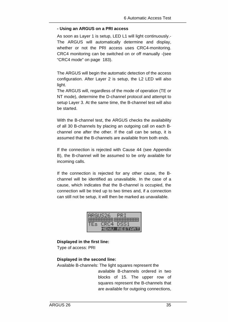
Displayed in the first line:Type of access: PRI
Displayed in the second line:Available B-channels: The light squares represent the
available B-channels ordered in twoblocks of 15. The upper row ofsquares represent the B-channels thatare available for outgoing connections,

6 Automatic Access Test
36 ARGUS 26
the lower row represents those thatcan be used for incoming calls.-left: B-channel 1right: B-channel 30
Displayed in the third line:
Operation mode: NTs = NT Simulation Slave Mode(see “Clock mode” on page 175)NTm = NT Simulation Master ModeTEs = TE Simulation Slave ModeTEm = TE Simulation Master Mode
Layer 1 mode: With (CRC) and without CRC4(NoCRC)
D-channel protocol: 1TR6, DSS1, none, BILINGUAL, Auto, CorNetN , CorNetT, QSIG or VN4
Displayed in the fourth line:The ARGUS displays the current assignment of the threesoftkeys below.
Test sample:
- The test found that it is a PRI multiple device access usingCRC4-monitoring
and the DSS1 protocol. All 30 B-channels are availableand can be used for outgoing or alternating connections.
The B-channel test cannot distinguish betweenalternating and exclusively "outgoing" B-channels.
- The ARGUS is in the NT-Simulation Master mode and isconnected to a terminal using the D-channel protocolDSS1 without CRC4-monitoring. B-channel 11 is notavailable.

6 Automatic Access Test
37ARGUS 26
- The first 10 B-channels are configured in the exchange asincoming -channels only (seen from the viewpoint of theterminal), while B11-B30 can be used for outgoing oralternating connections.
- The ARGUS is not properly connected (e.g. wrongcabling) or the network is not in order.
- Operating the ARGUS on a POTS access
The following will be displayed:
Powermeasurement idle

6 Automatic Access Test
38 ARGUS 26
- Status display
The ARGUS automatically determines the configuration ofthe access and the protocol used and inserts bothparameters in the remaining tests. Thus manualconfiguration of the ARGUS is unnecessary. However, it ispossible to manually change the protocol using theConfiguration menu (see Chap. 16.2.2 Select the D-channelprotocol page 173).
The status of the access under test (PRI, U-interface(optional), BRI or POTS) is always displayed in the first line.
It must be mentioned again, that the ARGUS onlydetermines the general bus status once when switched onor when the ARGUS first connected. On the other hand, the status of the protocol stacks forLayer 1, 2 and 3 will be continually monitored and displayed.
If an error occurs in the B-channel test (e.g. access is notplugged-in), the ARGUS will depending on the class of error(see “Error messages” on page 86) either repeat theinitialization or show an error message.-
In the Main menu, you can scroll through the available
menus with the < ↓ > key:
Status display
Main Menu
Repeat B-channel test
Pre
ssM
EN
U
scrollfurther
Return to Status display
The ARGUS opensthe menu marked witha →.
MarkedMenu List is
continued

6 Automatic Access Test
39ARGUS 26
With the < >, you can open the menu currently marked withthe → (in the example Single Tests).
Using the numeric keys to start a function:
Using the numeric keys, you can start important ARGUSfunctions directly, regardless of the currently active menulevel:
Numeric key 2Start Service TestNumeric key 3 Start Supplemental Service Test
PRI access BRIaccess
U-interfaceaccess(optional)
POTSaccess
Single Tests Single Tests Single Tests Single Tests
Test Manager Test Manager Test Manager _______
Automat.Tests Automat.Tests Automat.Tests Automat.Tests
________ Level
Measuring
Level
Measuring
Level
Measuring
L1 Status L1 Status ________ _______
Configuration Configuration Configuration Configuration
access access access access
X.21
Single Tests
Automat.Tests
Configuration
access
Name of the opened menu
scrollfurther
Return to previously shownDisplay
The ARGUS opensthe type of function/submenu marked with
List iscontinued

6 Automatic Access Test
40 ARGUS 26
Numeric key 4 Start Auto. TestNumeric key 6 Start Test ManagerNumeric key 7 Entry of your own and remote call numbers in the speed-dialing memory numeric key 8 Trace ON/OFFNumeric key 9 Start Bit Error Rate Test (BERT)
If a function is called where the ARGUS expectsthe entry of a digit, pressing a number key will beinterpreted as the expected input.

7 Access menu
41ARGUS 26
7 Access menu
7.1 Open the Access menu
If the parameters displayed at power on are not accepted,the Access menu will open automatically.However, you can also open the Access menu at any timefrom the Main menu:
Operation table:Throughout the remaining manual, under each display, youwill find a table that briefly describes the operation of theARGUS in the current situation.
On the left side of the table, you will find all of the ARGUSkeys that are available for the user to press in the currentstate (e.g. ↓ for the ↓-key or < ↓ > for the correspondingsoftkey).
On the right side of the table, you will find an explanation ofthe function of each key in this context.
Operation
< RESTART > Repeat B-channel test
< MENU > Open the Main menu
< ↓ > Select the Access menu
< > Open the Access menu
< > Return to the status display
Pre
ssM
EN
U

7 Access menu
42 ARGUS 26
means for example, that the ARGUS expects theuser to enter data on the numeric keypad at thispoint
7.2 Selection of the physical access
In the Access menu, the user must select the type ofphysical access to which the ARGUS is connected. Whenthe ARGUS is restarted, the settings used last will besuggested as the default.-
If Automatic is selected, a fully-automatic process will bestarted: The ARGUS will automatically determine the type ofinterface (BRI, PRI or POTS) and set the access to TE-mode.
To test a U-interface access, the ARGUS must beconnected via the optional U-interface adapter to the U-interface access. In this case, the ARGUS must be set to thephysical access BRI:-
The Access Mode menu will open automatically: Inthe case of a U-interface access, you must choose- as Access Mode - TE Automatic, TE P-P or TE P-MP.

7 Access menu
43ARGUS 26
On a BRI or U-interface access, the Access Mode will bedetermined automatically (PP or P-MP); on a PRI access, itwill be set to PP.The ARGUS will determine which D-channel protocol isused on the BRI, PRI or U-interface access and perform theB-channel test - after the level has been measured (only on aBRI access), the ARGUS will return to the Main menu.
Operation
< ↓ > Select desired access
< > confirm
If you select a S-Bus Interface (BRI) POTS (analog) interface S2M interface (PRI)the Access Mode menu will openautomatically:
< > Return to the Main menu
Connection of the ARGUS to a U-interface access: (optional)
What the LED on the U-Interface Adapter indicates: LED is red: not activated, e.g. cable not connectedcorrectly-LED flashing slowly - once per second - (green/red): U-interface is activated; the ARGUS, however, is deactivated LED flashing quickly - twice per second - (green/red):ARGUS is activated, U-interface is deactivatedLED is green: everything correct
access viathe Line jack
Connection to a

8 Select the Access Mode
44 ARGUS 26
8 Select the Access Mode
The Access Mode menu is not selectable from the Mainmenu. It opens automatically once the physical access isselected in the Access menu.
8.1 Operation on a BRI or PRI access
The following settings are possible:
8.1.1 TE-Simulation mode
TE automaticOn a BRI access, the ARGUS will automaticallydetermined the D-channel Layer 2 mode (PP or P-MP).If the ARGUS determines that the access supports bothmodes, the following Configuration menu will open:
TE P-P or TE P-MP
Afterwards, the access and the protocol stack will beinitialized in accordance with the selected setting. When the ARGUS finds a PRI access, it will enter TE P-P mode.The ARGUS will then jump to the Main menu.
Operation
< ↓ > Select the desired L2 mode.
< > Confirm and the ARGUS will return to theMain menu.-
< > Return to the Access Mode menu

8 Select the Access Mode
45ARGUS 26
8.1.2 NT-Simulation mode P-P or P-MP
NT P-P or NT P-MP
Afterwards, the access and the protocol stack will beinitialized in accordance with the selected setting.- When the ARGUS finds a PRI access, it will enter TE P-P mode.The ARGUS will then jump to the Main menu.

8 Select the Access Mode
46 ARGUS 26
8.1.3 Permanent circuit
Besides dial-up connections to any subscriber, ISDN alsosupports the use of permanent circuits switched to a specificremote location.
These permanent circuits are available after setting upLayer 1, in other words after synchronizing both terminals byexchanging HDLC-frames.
The location where the clock is generated can be selected(see Chap. 16.2.4 Clock mode page 175).
As a quick test of a permanent circuit, you can simply callthe opposite end using a selected B-channel.- However, for a more revealing test of a permanent circuit,you should perform a bit error rate test. Both ends of the permanent circuit must use the samechannel.
Telephony on permanent circuits
The function can be started with the -Key or via thePhone / connec. function in the Single tests menu (seeChap. 11 page 125).After the B-channel for the permanent circuit is selected, thetelephone connection will be setup automatically.
The ARGUS inPermanentcircuit mode

8 Select the Access Mode
47ARGUS 26
.
Operation
< ABORT > Terminate permanent circuit
< TM > Call the Test Manager(see “Test Manager” on page 140 )
B-channel usedDuration of the Permanent

8 Select the Access Mode
48 ARGUS 26
BERT on permanent circuits
A number of variations are possible in testing the permanentcircuit with the bit error rate test.
In the simplest case, a B-channel loop will be set up at theremote end.
Start the BERT from the Single tests menu / BERTsubmenu / BERT start (see “BERT startwait” on page 94).After selection of the channel to be tested (B-channel or D-channel), the ARGUS will send the test pattern, receive itback and evaluate it accordingly.-
The displays and operation are, in largest part, similar tothose of a BERT on a dial-up connection (see Chap. 10.3 Biterror test page 92), you simply need not enter call numbersor select a service.
In the case of a BRI access in end-to-end mode (see “Biterror test” on page 92 and on page 100 “Bert wait”), it isalso possible to run a BERT in the D-channel.
In this case, the channel select window will open:On a BRI access:
On a PRI access:In the case of a PRI access in end-to-end mode (see “Bit
Operation
< ↓ > Selecting a channel
< > Confirm the selected channel and start thetest.When selecting a B-channel, the B-channelselect window will open to allow you to choosethe desired B-channel.
<ABORT > Close window and discard any selection thatwas made-

8 Select the Access Mode
49ARGUS 26
error test” on page 92and on page 100 “Bert wait”), a BERTcan be run- in the D-channel- in all B-channels- in all B-channels and in the D-channel (all framed)- in selected B-channels - in all channels and time slot 0 (all unframed).
In the channel selection window, the upper squaresrepresent time slot 0 (upper display line left square), the D-channel is represented by the left square on the lowerdisplay line and the B-channels are assigned to the twoblocks of 15 (upper display line B-channels 1 to 15, lowerdisplay line channels 16 to 30). The selected channels areindicated in the upper row by hidden squares.-- The hiddensquares in the lower row indicate the current position of thecursor.
The cursor is moved with the arrow keys: ↓-Key moves the cursor one position to the left↑Ø−Κεψ moves the cursor one position to the right.The channels can also be marked with the cursor directlyusing the numerical keypad: If you enter the digits 18, thecursor will jump to B-channel 18. If you enter *, the cursorwill move to time slot 0 and the entry of the # will move thecursor to the D-channel.
Time slot 0 can only be selected, when all otherchannels (all B-channels and the D-channel) areselected (i.e are free).-
If the right softkey shows <ON>, pressing the softkey <ALL>will select all B-channels and the D-channel (Mega BERTframed). When the right softkey shows <OFF>, pressing thesoftkey <ALL> will deselect the currently selected channels.

8 Select the Access Mode
50 ARGUS 26
TimeSlot 0
D-
No channel has been selectedand the cursor is at B-channel10.-
The channel, at whichthe cursor is found, isfree.
Examples of channel selection:
The cursor is at B-channel 10 and thechannel is not selected
ON
B-channel 10 is free andselected.
MegaBERTframed
All channels will be selected,except time slot 0
The cursor is at time slot0.
ON
Time slot 0 has beenselected-
MegaBERTunframed
ALL
The cursor is at B-channel 10 and thechannel is not selected

8 Select the Access Mode
51ARGUS 26
After the channels have been selected, the BERT is started
with the -Key.
The ARGUS displays the following during the BERT:
Operation
< ERROR > Injects an “artificially generated” bit error (tocheck the reliability of the test)
< TM > Call the Test Manager (see “Test Manager” onpage 140)
<ABORT > Test - interrupting
The channels 5 to 8were individuallymarked with the cursorand selectedwith -<ON>-; the cursoris at B-channel 8.
Channels 5 to 8 and20 to 23 have beenselected.The cursor is atchannel 24. Channel24 cannot be selected,since it is busy.
Bit rate or busy channel
DetectedBit errors
Remaining timeof theSynchronicityof the bit pattern
Bit
LOS-counter
8 Select the Access Mode
52 ARGUS 26
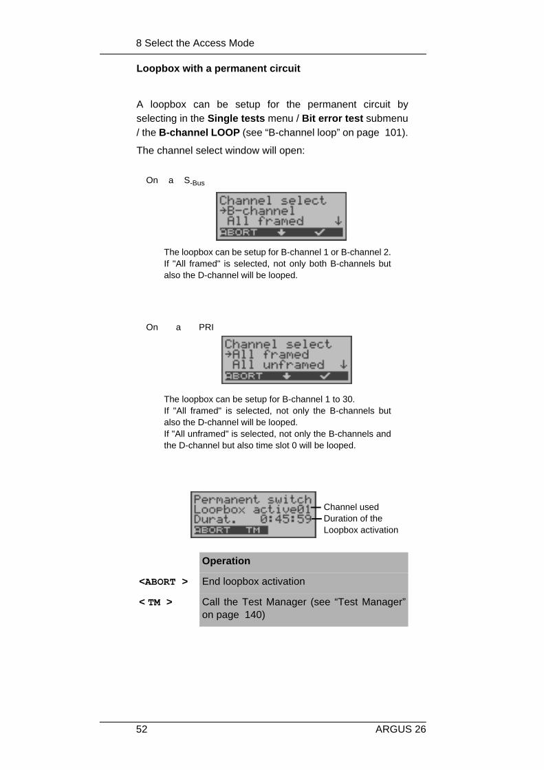
Loopbox with a permanent circuit
A loopbox can be setup for the permanent circuit byselecting in the Single tests menu / Bit error test submenu/ the B-channel LOOP (see “B-channel loop” on page 101).
The channel select window will open:
.
Operation
<ABORT > End loopbox activation
< TM > Call the Test Manager (see “Test Manager”on page 140)
The loopbox can be setup for B-channel 1 or B-channel 2.If "All framed" is selected, not only both B-channels butalso the D-channel will be looped.
On a S-Bus
The loopbox can be setup for B-channel 1 to 30.If "All framed" is selected, not only the B-channels butalso the D-channel will be looped. If "All unframed" is selected, not only the B-channels andthe D-channel but also time slot 0 will be looped.
On a PRI
Duration of the Loopbox activation
Channel used

8 Select the Access Mode
53ARGUS 26
Once you leave the permanent circuit mode
In the Main menu, open the Access menu. The AccessMode window will open automatically. In this window, youcan change the operating mode of the ARGUS.
The Access Mode menu will
Changing theoperating mode

8 Select the Access Mode
54 ARGUS 26
8.1.4 BRI/PRI Monitor
The ARGUS accepts all of the D-channel signals from theBRI or PRI access and sends these D-channel signals overthe serial interface to a PC, which must be running ARGUSWINplus or WINAnalyse.- The bus and Layer 1 are notinfluenced by the monitoring.
Display during operation on a BRI access:
After starting the Monitor function, the ARGUS will first be inMonitor mode (the monitor is not yet active): the second lineshows the evaluation of the level on the NT-side (OK or <<(too low), >> (too high) or _ (no level)).
Display during operation on a PRI access:
Operation
< MENU > Opens the list of menus that are available inMonitor mode.
< START > Start Monitor , automatically opens theassociated display window
ARGUS inMonitormode,Monitoringnot yet

8 Select the Access Mode
55ARGUS 26
When the Monitor function is active, the Trace LED will beon.
The captured D-channel signals will be sent via the serialinterface to the connected PC, which must be running eitherARGUS WINplus or ARGUS WINAnalyse.
ARGUS messages on a PRI access
As soon as a change occurs, the ARGUS will send a time-stamped report of the following alarms/states to the PC,which will evaluate them:
- Signal- FAS- CRC4det- A-Bit- AIS
The ARGUS will check the following values and countersevery second and, in the event of a change, will pass themon the PC:
- Sa5-Bit (Rx)- Sa6-Bit (Rx)- E-Bit- Ecnt- CRC Err.- Cod.Err.
< LISTEN> The speech path will be switched onto a B-channel: First the B-channel select dialog willopen. After selecting a B-channel, it will bepossible to listen to the voice data (in thedirection Network --> User) on this channel.
< ABORT > Once Monitoring is stopped, the ARGUS willreturn to the Monitor display (Monitoring notactive)
While the PRI Monitor is active, the ARGUSdisplays the L1 status (see L1 status in PRIMonitor Mode)-
Received signals
Duration of theMonitor- function
8 Select the Access Mode
56 ARGUS 26
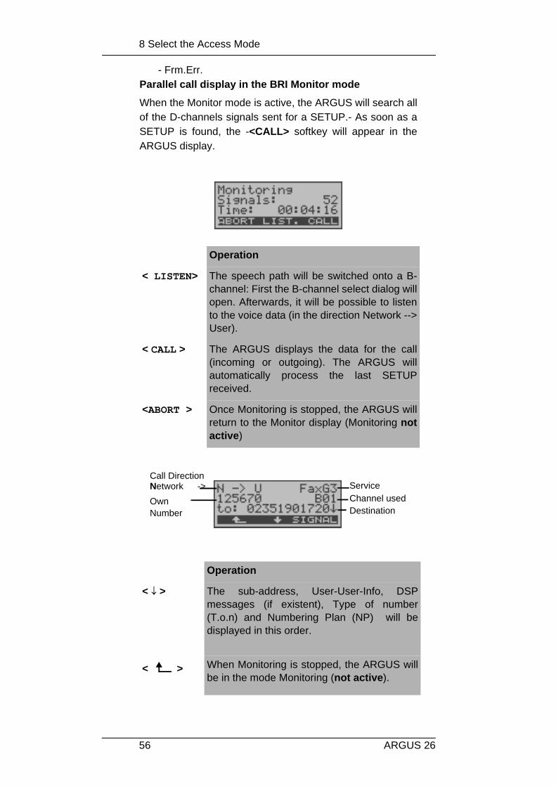
- Frm.Err.Parallel call display in the BRI Monitor mode
When the Monitor mode is active, the ARGUS will search allof the D-channels signals sent for a SETUP.- As soon as aSETUP is found, the -<CALL> softkey will appear in theARGUS display.
Operation
< LISTEN> The speech path will be switched onto a B-channel: First the B-channel select dialog willopen. Afterwards, it will be possible to listento the voice data (in the direction Network -->User).
< CALL > The ARGUS displays the data for the call(incoming or outgoing). The ARGUS willautomatically process the last SETUPreceived.
<ABORT > Once Monitoring is stopped, the ARGUS willreturn to the Monitor display (Monitoring notactive)
Operation
< ↓ > The sub-address, User-User-Info, DSPmessages (if existent), Type of number(T.o.n) and Numbering Plan (NP) will bedisplayed in this order.
< > When Monitoring is stopped, the ARGUS willbe in the mode Monitoring (not active).
ServiceChannel usedOwn
Number
Call DirectionNetwork ->
Destination

8 Select the Access Mode
57ARGUS 26
L1 Status in PRI Monitor mode
The L1 status function is only available in the PRI Monitormode.- The Layer 1 alarms and messages are presented inseveral windows, which permit detailed statementsregarding the state of the PRI access and the transmissionline (For further information, see the CCITT/ITU guidelinesG.703 and G.704).-When the function is started, it will first automatically openthe “L1 status TE” function, which shows the “TE-sideparameter”. For a comprehensive explanation of thedisplayed information: see “The L1 status of a PRI access”on page 165.
< SIGNAL > The ARGUS switches to the active Monitorwindow. Now, if you press <CALL>, theARGUS will again display the callparameters.
Operation
< ↓ > Select L1 status
< > Open the L1 status function
< > Return to the Monitor Mode window
↓ -Key Scroll through the display
< NT > Switch to the “L1 status NT” function; the “NT-side parameter” will be displayed
< RESET > Reset the History function and all counters
< ABORT > Quit the function and return to the menu list

8 Select the Access Mode
58 ARGUS 26
8.1.5 BRI / PRI Recorder
In the Recorder mode, the ARGUS passively monitors theconnected BRI or PRI access.
The ARGUS records all of the D-channel signals sent inboth directions without affecting the access or Layer 1.
Unlike in the Monitor mode, the recorded D-channel signalswill be saved in the ARGUS’s internal Flash memory and notsent to a PC.
The storage is organized as a ring buffer, i.e. as soon as theFlash memory is full, the ARGUS will automaticallyoverwrite the oldest data.-
Operation
< ↓ > Mark BRI Recorder or PRI Recorder
On a S-Bus
On a PRI

8 Select the Access Mode
59ARGUS 26
Recording function - activated
When the Recording function is active, the Trace LED willflash. The ARGUS displays the number of signals receivedand the duration of the recording in hours:mínutes:seconds.Operation on a BRI access:
During the recording, the ARGUS also displays incomingand outgoing calls (see “Parallel call display in the BRIMonitor mode” on page 56).
Operation on a PRI access:
< > Start the Recorder function.The ARGUS is now in Recorder mode(Monitoring is not yet active!) and will checkthe levels on the NT and TE sides of the BRIaccess. Displayed in the second line: Level onthe NT-side (<< too low, >> too high, OK, ___no level), level on TE-side (<< too low, >> toohigh, OK, ___ no level)
< > Return to the Main menu
<MENU > Opens a list of menus or functions, which areavailable in Recorder mode.
< START > Start Recording , automatically opens theassociated display window
Operation
< ABORT > Quitting the active recording function. TheARGUS is now in the “Recording” mode.
Time Slot 16

8 Select the Access Mode
60 ARGUS 26
The ARGUS saves a timestamped report of any changes inthe following alarms/states:
- Signal- FAS- CRC4det- A-Bit- AIS
The ARGUS will check the following values and countersevery second and, in the event of a change, will save them:-
- Sa5-Bit (Rx) / (Tx)- Sa6-Bit (Rx) / (TX)- E-Bit- Ecnt- CRC Err.- CRC rel.- Cod.Err.- Cod.rel- Frm.Err.
< LISTEN> The speech path will be switched onto a B-channel. First the B-channel select dialog willopen. After selecting a B-channel, it will bepossible to listen to the voice data (in thedirection Network -----> User) on this channel.

8 Select the Access Mode
61ARGUS 26
Flash Data Management
In the Recording mode, several functions are available tomanage the data recorded and saved in the Flash memory: - PC load all- PC load session- Reset Flash- Info Flash
• PC load all
With the PC load all function, all of the contents of the Flashmemory will be downloaded via the serial interface to thePC, which must be running either WINplus or WINanalyse.
Operation
< MENU > Starting/opening the functions/submenusavailable in Recorder Mode.-
< ↓ > Select PC load all
< > The download to the PC begins.
< > Return to Recorder mode (Recording not active)
Operation
< ABORT> The download is stopped. Return to the menu.
Pres
sM
EN
U

8 Select the Access Mode
62 ARGUS 26
Once the download has been successfully completed, theARGUS will ask whether the Flash memory should bedeleted:
• PC load session
In the ARGUS, the storage in the internal Flash is organizedas a ring buffer, which can hold the data from a series ofseveral sessions (i.e. independent trace recordings).-- At thestart of each session, the date and time will be written in thering buffer.-
The PC load session function transfers all of the datasession-by-session to the PC on which either WINplus orWINanalyse must be running. The time and date that thesession was started will be displayed in WINplus/WINanalyse.
Operation
< DELETE > The contents of the Flash memory will bedeleted.
< ABORT> The contents of the Flash memory will notbe deleted. Return to the menu.
Pres
sM
EN
U

8 Select the Access Mode
63ARGUS 26
Once a session has been successfully loaded, the ARGUSwill ask whether another session should be loaded:
Once the download has been successfully completed, theARGUS will ask whether the Flash memory should bedeleted:
Operation
< MENU > Starting/opening the functions/submenusavailable in Recorder Mode.-
< ↓ > Select PC load session.
< > The loading of the individual sessions willstart.
< > Return to Recorder mode (Recording not activate)
Operation
< ABORT> Stop loading the session. Return to the menu.
Operation
< CONT. > The next session will be downloaded to thePC.
< ABORT> Stop the loading and return to the menu.
Operation
< DELETE > The contents of the Flash memory will bedeleted.

8 Select the Access Mode
64 ARGUS 26
• Internal decoding
The ARGUS will decode the D-channel data stored in theFlash memory:
• Info Flash
With this selection, you can read the status of the data in theFlash memory:- The number of saved sessions
(displayed in the second line)- Free memory in MB and in percent
(displayed in the third line)
< ABORT> Continue to the menu without deleting thecontents of the Flash memory.
Operation
< ↓ > Select Internal Decoding
< > Start the Internal Decoding function
< > Return to Recorder mode (Recording not active)
↓ -Key Scroll through the display
< DECODE > Start decoding one level deeper for a moredetailed view (select from 3 levels)
< ABORT > Continue to the menu
< = signalDirection
> = signalDirection user

8 Select the Access Mode
65ARGUS 26
• Reset Flash
The Reset Flash function will delete the entire contents ofthe data Flash memory.
Operation
< ↓ > Select Info Flash
< > View information about the status of the datain the Flash memory.
< > Return to Recorder mode (Recording not active)
< > Continue to the menu
Operation
< ↓ > Select Reset Flash

8 Select the Access Mode
66 ARGUS 26
< > Start the Reset Flash function
< > Return to Recorder mode (Recording not active)
< DELETE > The contents of the Flash memory will bedeleted. The procedure can take severalseconds.- The ARGUS will show theprogress of the deletion as the percentagedone.- It is not possible to stop the process ofdeletion. As soon as the entire FLASH memory iserased, the ARGUS will automatically returnto the next higher menu.-
< ABORT> Return to the menu; the contents of theFlash memory will not be deleted.

8 Select the Access Mode
67ARGUS 26
8.2 Operation on a U-interface access (optional)
8.2.1 TE simulation mode
TE automaticThe ARGUS will automatically determined the D-channel Layer 2 mode (PP or P-MP). If the ARGUSdetermines that the access supports both modes, thefollowing Configuration menu will open:
TE P-P or TE P-MPAfterwards, the access and the protocol stack will beinitialized in accordance with the selected setting. TheARGUS will then jump to the Main menu.
8.2.2 Permanent circuit
similar to a BRI access
Operation
< ↓ > Select the desired L2 mode.
< > The ARGUS will switch to the L2 mode andreturn to the Main menu
< > Continue to the Access Mode menu

8 Select the Access Mode
68 ARGUS 26
8.3 Operation on a POTS (analog) access
8.3.1 POTS terminal
The Argus behaves like a POTS (analog) terminal. TheARGUS will then jump to the Main menu.
8.3.2 POTS monitor
Essentially, the POTS (analog) monitor provides a highimpedance tap that does not influence the interface.You can listen to the line with the integrated handsetwithout having the ARGUS send on or otherwiseinfluence the interface.--
If the access supports CLIP, the ARGUS will display the
Operation
< MENU > Opens a list of the menus available in Monitormode-
< START > Start Monitor , automatically opens theassociated display window
Operation
↓ -Key Display further information(e.g., transferred charges)
< DELETE > The display will be cleared.
< ABORT> Quits the POTS Monitor function.
Voltage levelwhen “on hook”

8 Select the Access Mode
69ARGUS 26
caller’s number.The DTMF characters dialed by both telephone subscriberswill also be displayed. Any additional DTMF-characters will be appended to theline, which will shift left for each character once it is full.
An incoming call will be signalled acoustically.

9 Operation on an X.21 access (optional)
70 ARGUS 26
9 Operation on an X.21 access (optional)
The ARGUS will perform a bit error test on the X.21 accessin accordance with the ITU guidelines G.821 and G.826. Besides the measurement results, the ARGUS will alsodisplay the X.21 data rate.
Use the adapter cable - available as an option - to connectthe ARGUS to the X.21 network.
In the Access menu, select "X.21":
Operation
< ↓ > Select X.21
< > Confirm,the ARGUS will jump to the status display
< > Any access change will be ignored,-the ARGUS will jump to the status display
X.21 Interface Adapter
Connection to Connection to X.21networkor X.21 standard

9 Operation on an X.21 access (optional)
71ARGUS 26
9.1 BERT start
The ARGUS will detect the clock of the X.21 permanentcircuit, calculate the data rate and then automatically searchfor the channels used.- On these channels, the ARGUS willsend the test pattern (see Chap. 16.3.4 Selecting the BERTbit pattern page 195) selected, receive it again and evaluateit in accordance with the ITU guidelines G.821 and G.826(loopbox required at the remote end).
During the test, the ARGUS will show the X.21 data rate, theremaining test time in hours:minutes:seconds, the number ofbit errors that have occurred so far and the sychronicity ofthe bit pattern.
Operation
< ERROR > Injects an “artificially generated” bit error,which can demonstrate the reliability of themeasurements when running end-to-endtests
Pre
ssM
EN
U
X.21 data rateNumber of biterrors that haveoccurred thus far
RemainingSynchronicityof thebit pattern

9 Operation on an X.21 access (optional)
72 ARGUS 26
When a bit error is detected, this will be signaledby a brief alarm (if the alarm is enabled); in theevent that the synchronization is lost, a constantalarm will sound.- These alarm bells can beswitched ON/OFF (see Chapter 16.5.7 Alarm bell )
The measurement time for the BERT can be specified withthe Configuration function (see Chap. 16.3.1 BERT -duration page 191).
After the test is over, the ARGUS will display the test results:
Display results:
Furthermore, it is possible to display more characteristicvalues (with the <MORE> softkey), the ARGUS will determine
< RES.> Restart the bit error test: The test time andnumber of bit errors will be reset.-
<ABORT > Abort the bit error test
Operation
< MORE > Display additional test results
< MENU > Return to the Bit error test menu
First line: Bit pattern and X.21 data rate
Second line: Transferred data in kBits (in the example10309 kBits)
Third line: Number of the bit errors that have occurred(in the example 10)Bit error rate (in the example 9.7·10-7 (=0.00000097))The evaluation of the results depends onthe error threshold that you set (see “BERT- Setting the Error level” on page 193). OK = bit error rate is less than the errorthreshold (set by the user) and NO = biterror rate is above the error threshold.

9 Operation on an X.21 access (optional)
73ARGUS 26
the following in accordance with the ITU-T G.821 and G.826:See Chapter 10.3.1 BERT startwait page 94
The BERT test results can be saved in the ARGUS:- on page98 “Saving BERT test results in the ARGUS”.
BERT wait
In this mode, the BERT will wait for the BERT at the remoteend which is necessary for an end-to-end test: see “Bertwait” on page 100.

10 Single Tests
74 ARGUS 26
10 Single Tests
Open the Single menutest menu:
Open the functions in the Singletests menu:
Operation
< RESTART > Repeat B-channel test
< PressMENU >
Open the Main menu
< ↓ > Select the Single tests menu
< > Open the Single tests menu
< > Return to the status display
Operation
< > Return to the Main menu
< ↓ > Mark the desired function
< > Open the function marked with the →
Pres
sM
ENU

10 Single Tests
75ARGUS 26
10.1 Supplementary Services Test
The ARGUS checks, which supplementary services aresupported by the access being tested.-
10.1.1 Supplementary Service Test - 1TR6
(Only on a BRI or U-interface (optional) access)
Description
The ARGUS checks, which of the services listed below aresupported by the exchange for the BRI or U-interface access(running the 1TR6 protocol) that is being tested:
Sperre Blocking enabled foroutgoing calls
AWS1 Call forwarding type 1 enabled(continuously)
AWS2 Call forwarding type 2 enabled(case by case)
Anschluss GBG Access belongs to a Closed UsersGroup
Geb.anzeige Display of charges is setup
Rufnummern-Id Setup call number identification - against malicious calls
Operation
< > Return to the status display
< ↓ > Select Supplementary services
< > Open Supplementary services

10 Single Tests
76 ARGUS 26
Operation
< ABORT > Abort the testReturn to the Single tests menu
As soon as the supplemental servicesinterrogation is finished, the ARGUS willdisplay the results in the second and thirdlines of the display:
< ↓ > Scroll through the test results+ means that the suppl.service is enabled- means that the suppl.service is not enabled
< > Continue to the Single tests menu
After the test is over,the results windowwill openautomatically

10 Single Tests
77ARGUS 26
10.1.2 Suppl.service interrogation in DSS1
Currently, the ARGUS can individually test the followingDSS1 supplementary services:
On a BRI access:
TP Terminal Portability Moving the terminal on the bus
HOLD Hold Hold/Broker DDI Direct dialling in Direct dialling in to an
extension on a PBX(on a P-P)
MSN Multiple Subscriber Number
Direct dialing into aP-MP
CLIP Calling Line Identification Presentation-
Display the caller’s number
CLIR Calling Line Identification Restriction-
Suppress the caller’s number
COLP Connected Line Identi-fication Presentation
Display the call number of the called subscriber with whom one is connected
COLR Connected Line Iden-tification Restriction
Suppress the number of the subscriber with whom one is connected
CFU Call Forwarding Unconditional
Call Forwarding (Anrufweiterschaltung) continuously
CFB Call Forwarding Busy Forward calls when busy CFNR Call Forwarding No
ReplyForward calls when no answer
CW Call Waiting Call waitingCCBS Completion of Calls to
Busy Subscriberautomatic callbackif the party called is busy
CCBS-T Completion of Calls to Busy Subscriber
automatic callbackif the party called is busy (on P-P)
CCNR Call Complete No Response
automatic callbackif the party called does not answer
CCNR-T Call Complete No Response
automatic callbackif the party called does not answer (on P-P)

10 Single Tests
78 ARGUS 26
On a PRI accessOn a PRI access, the following supplementary services willbe tested:
CLIP, CLIR, COLP, COLR, DDI, CFU,CFB CFNR-T, CW, CCBS-T, MCID, CUG, CD, AOC,
SUB, UUS
MCID Malicious CallIdentification
Identification of maliciouscallers (call tracing)
3pty Three party Three party conferenceECT Explicit Call Transfer Call transfer or directed call
forwardingCD Call deflection active call diversion
in the call setup phase - by the party called-
AOC Advice of Charge Advice of chargesSUB Sub-addressing Sub-addressing is possibleUUS User-to-User
SignallingTransfer of user data
CUG Closed User Group Access belongs to a Closed Users Group
Operation
< > Return to the Main menu
< > Select the Supplementary service test
< ↓ > Confirm your selection
The window, Enter numbers, will now open:

10 Single Tests
79ARGUS 26
Select the service and B-channel:
Select the service and B-channel for the completesupplementary service test.:
Enter your Own number; the suppl.servicestest is performed in part with a self call.
< DEL > Delete individual digits
< > confirm
< > Continue to the Single tests menu
Operation
< ↓ > Select service
< > Confirm the service and the B-channelselection dialog will open.
< > Abort and return to the Single tests menu
Enter the B-channel (by default, the last B-channel used will be suggested). If you enteran *, the ARGUS will choose any B-channelthat is free.
< DEL > Delete the B-channel digit-by-digit
< > Confirm
< > Abort and return to the Single tests menu
B-channel 2 isavailable.

10 Single Tests
80 ARGUS 26
Select TestSelect:
Test case TP
The ARGUS will setup a self call to test the TP supplementalservice.
HOLD Test
For this test, the ARGUS will make a self call.
Result: + = HOLD is possible on this access- = HOLD is not possible on this access
CLIP Test (CLIP / CLIR / COLP / COLR)
For this test, the ARGUS will make up to three self calls one
Operation
< ↓ > Select a test (e.g. TP test)
< > Start the test
< > Return to the Single tests menu
Operation
< >
The test results are displayed in the secondline:+ = TP possible on this access- = TP not possible on this accessReturn to the Suppl.serv.test menu, where youcan select the next type of test.

10 Single Tests
81ARGUS 26
after the other. In this test, the ARGUS checks whether the 4supplementary services CLIP, CLIR, COLP and COLR aresupported on the access under test.
The test will be performed automatically for all foursupplementary services.
Test results:
CLIP
Will the calling subscriber's number be displayed at thecalled subscriber?- = no += yes
CLIR
Will the display of calling subscriber's number at the calledsubscriber be suppressed or is it possible to temporarilysuppress the display?-- = no t = temporary p = permanent* = no result, since CLIP is not setup
COLP
Will the call number of the subscriber who answered bedisplayed on the caller's phone?- = no += yes
COLR
Will the display of the call number of the subscriber whoanswered be suppressed on the caller's phone or is itpossible to temporarily suppress the display?-- = no t = temporary p = permanent* = no result, since no COLP is setup
Operation
< ↓ > Scroll through the test results
< > Return to the Suppl.serv.test menu

10 Single Tests
82 ARGUS 26
The suppl. services CLIP and CLIR as well asCOLP and COLRwill be tested in pairs. If a -CLIR or COLR is setupconstantly, it is not possible to make a statement-
with any degree of certainty
DDI Test
Can a caller directly dial in to an extension on the PBXaccess under test?-- = no += yes
MSN Test
Is the supplemental service MSN available?- = no += yes
CF Test ( CFU / CFB / CFNR )
This test checks whether the 3 supplementary servicesCFU, CFB and CFNR are supported on the access undertest. The test is automatically performed for all threesupplementary services.
The CF test attempts to setup a call diversion tothe call number that is in the speed-dialing memorylocation for “destination no. 1”. The CF test cannotbe performed, if this location does not contain avalid call number to which it is possible to divert acall.
Test results:
CFU
Can this access immediately forward an incoming call?
Operation
< ↓ > Scroll through the test results
< > Return to the Suppl.serv.test menu

10 Single Tests
83ARGUS 26
- = no += yes
CFB
Can this access forward an incoming call when it is busy; inother words does it support Call Forwarding Busy?-- = no += yes
CFNR
Can this access forward an incoming call when it is notanswered?- = no += yes
CW Test
Does the access under test support call waiting?- = no += yes
CCBS or CCBS-T Test on a P-P Access
Will the access under test automatically recall a remotesubscriber, if the number called was busy?- = no += yes
CCNR or CCNR-T Test on a P-P Access
Will the access under test automatically recall a remotesubscriber if the call was not answered?- = no += yes
MCID Test
Does the access tested allow identification of maliciouscallers (call tracing)? - = no += yes
3pty Test
Does the access under test support a three-partyconference call?
For this test, you need the assistance of a remotesubscriber, whose call number must be entered.

10 Single Tests
84 ARGUS 26
- = no += yes
ECT Test
Is an explicit call transfer supported by the access undertest?
For this test, you need the assistance of a remotesubscriber, whose call number must be entered.-- = no += yes
CD Test
Is an active call transfer supported in the calling phase onthe access under test?-
For this test, you need the assistance of a remotesubscriber, whose call number must be entered.-- = no += yes
AOC Test
The ARGUS checks whether the charges can be sent to theaccess under test. The test uses a call to oneself to checkboth AOC-D (AOC during a call) and AOC-E (AOC at theend of a call).-
SUB Test
A call is made to oneself and answered to check the transferof the sub-address in both directions.-
Are sub-addresses supported on the access under test?- = no += yes
Operation
< > Return to the Suppl.serv.test menu
10 Single Tests
85ARGUS 26
UUS Test
Does the access under test support the transfer of userdata?- = no += yes
CUG Test
The ARGUS will setup a self call. It then checks whether theaccess under test belongs to a closed user group.-- = no += yes

10 Single Tests
86 ARGUS 26
10.1.2.1 Error messages
If an error occurs during a suppl.serv.test or if it is notpossible to setup a connection, the ARGUS will display thecorresponding error code (second line in display) plus theerror class in clear text (third line in the display).
In the example, an error with the code 28 has occurred. Theerror belongs to the error class "wrong or invalid number". In the table below, you will find that this is an error from thenetwork and that it reports that the call number wasincomplete or in the wrong call number format (see“CAUSE-Messages – DSS1 Protocol” on page 228).
Distributing the error codes into error classes:
For further information regarding error codes:“ARGUS ErrorMessages” on page 232, “CAUSE-Messages – 1TR6Protocol” on page 230 and “CAUSE-Messages – DSS1Protocol” on page 228.
10.2 Service check
The ARGUS checks, which of the following services are
Errorclass
Description Cause (fromnetwork)1 TR6 DSS1
CauseARGUSinternal
A No or anotheraccess
__ __ 201,204,205,210,220
B wrong orinvalid number
53, 56 1,2,3,18,2122,28,88
152,161,162,199
C One or moreB-channels busy
10,33,59 17,34,47 ___
D Wrong service 3 49,57,58,6365,70,79
___

10 Single Tests
87ARGUS 26
supported by the access under test:
The test runs automatically.
For each service, the ARGUS will place a call to itself (to theaccess under test). However, the call will not be answeredso no charges will be incurred.
Service Name in the ARGUS display /abbreviation
Language Language / Lang
Unrestricted DigitalInformation
UDI 64kBit / UDI 64
3.1 kHz Audio Tel.analog / Tel.
7 kHz Audio 7 kHz audio / 7 kHz
Unrestricted DigitalInformation with tones /display
UDI+TA / UDI TA
Telephony Tel.ISDN / Tel.
Facsimile Group 2/3 Fax G3 / FaxG3
Facsimile Group 4 Class 1 Fax G4 / FaxG4
Teletex service basis andmixed mode and facsimileservice Group 4 Classes IIand III-
Mixed Mode / Mixed
Teletex Service basismode
Teletex / Ttx64
International inter workingfor Videotex
Videotex
Telex Telex
OSI application accordingto X.200
OSI
7 kHz Telephony Tel.7kHz / Tel7k
Video Telephony, first connection
Videotel.1 / Vid.1
Video Telephony, second connection
Videotel.2 / Vid.2
Three user-specificservices (optional)(see “Services” on page186)
Userspec.1 /Userspec.2 /Userspec.3 /

10 Single Tests
88 ARGUS 26
Operation
< > Select Service check
< ↓ > Confirm the selection and the Enter numbersdialog will open
< > Return to the Main menu
In the dialog, Enter numbers, enter your owncall number and the Service check will beperformed using a self call.-
< DEL > Delete the digit before the cursor
< > confirm
< > Continue to the Single tests menu
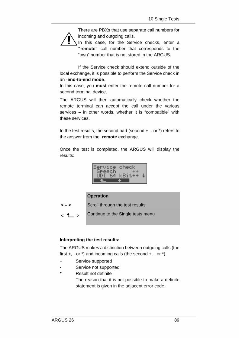
10 Single Tests
89ARGUS 26
There are PBXs that use separate call numbers forincoming and outgoing calls. In this case, for the Service checks, enter a“remote” call number that corresponds to the“own” number that is not stored in the ARGUS.
If the Service check should extend outside of thelocal exchange, it is possible to perform the Service check inan -end-to-end mode. In this case, you must enter the remote call number for asecond terminal device.
The ARGUS will then automatically check whether theremote terminal can accept the call under the variousservices – in other words, whether it is “compatible” withthese services.
In the test results, the second part (second +, - or *) refers tothe answer from the remote exchange.
Once the test is completed, the ARGUS will display theresults:
Interpreting the test results:
The ARGUS makes a distinction between outgoing calls (thefirst +, - or *) and incoming calls (the second +, - or *).+ Service supported- Service not supported * Result not definite
The reason that it is not possible to make a definitestatement is given in the adjacent error code.
Operation
< ↓ > Scroll through the test results
< > Continue to the Single tests menu

10 Single Tests
90 ARGUS 26
Displayed Description
+ + The self call functions OK or the remote end cantake the call for this service
+ - Call was sent successfully, however, it was rejectedon the remote end due to missing authorization. (Error class D in a B-channel message e.g. in aSETUP_ACK or CALL_SENT)
- An outgoing call with this service is not possible (Error class D without a B-channel message)
+ * Call was sent successfully, the call back or call tothe remote end failed (e.g., remote end busy or noB-channel available for the call back).(Error class B, C or E in a B-channel message)
* Wrong number, no B-channel available or othererror (Error class B, C or E without a B-channel message)
If the outgoing call is not successful, it is not possible tomake a statement about an incoming call. Therefore, youwill never see “- +” or “- *” on the display.
Example:
For outgoing, the Fax G4 service is OK. No statement ispossible about incoming. The error code 63 gives the coded cause of the error(see the table in the Appendix). In this case, it is recommended that you have someoneplace a call to the access under test using this service.
The Mixed Mode service is possible in both directions.
If an error of error class A occurs (see “Error messages” onpage 86) the Service test will be aborted.
An error of any other error class will coded in decimal (in theexample above 63), assigned to the respective service and

10 Single Tests
91ARGUS 26
then displayed.
10 Single Tests
92 ARGUS 26
10.3 Bit error test
The bit error rate test (BERT = Bit Error Rate Test) servesto check the transmission quality of the access circuit.
As a rule, the network operator will guarantee an averageerror rate of 1 x 10⁻⁷, in other words in long-term operation1 bit error in 10 million transmitted bits. A higher bit errorrate will be especially noticeable in transmitting data.
The application program detects the errors in the datablocks transmitted and requests that the remote partnersend them again, which reduces the effective throughput ofthe ISDN connection.-
In the bit error test, the tester establishes an ISDNconnection to a remote tester or places a call to itself, sendsa standardized (quasi-) random number string andcompares the received data with that which was sent. Theindividual bit errors are summed and depending on the testprocedure and equipment evaluated in accordance with theITU Guidelines G.821 and G.826.
During the test, the ARGUS counts the bit errors and afterthe test is done it calculates the bit error rate and otherparameters in accordance with G.821. Since the bit error test checks both B-channels in bothdirections at the same time, both B-channels are required. The duration of the BERT can be set in the Configuration/BERT (see “BERT - duration” on page 191) menu (defaultsetting = 1 minute).
As a rule, the quality of the network operator’s accesscircuits is quite good. Therefore, no bit errors should occurin a 1-minute test.
However, if an error occurs, the test should be repeated witha measurement time of 15 minutes to achieve higherstatistical precision. The access circuit is heavily distorted, ifmore than 10 bit errors occur within a test period of 15minutes.
Contact the network operator or the supplier of the PBXequipment and ask them to test your access circuit.

10 Single Tests
93ARGUS 26
The BERT can be performed in three different ways:
1. BERT in an extended call to oneself
A remote number is not needed, since the ISDNconnection is setup to oneself. In this case, the ARGUSrequires two B-channels for the test.
2. BERT with a loopbox
A loopbox (e.g., another member of the ARGUS familyof testers at the remote end) is required. The test uses one B-channel.
3. BERT end-to-end
This test requires a waiting remote tester such as anARGUS in the BERT wait mode .(see Chap. 10.3.2page 100) A bit pattern is sent to this tester. Independent of the received bit pattern, the remotetester uses the same algorithm to generate the bit-pattern that it sends back. Therefore, both directions are tested independently.-

10 Single Tests
94 ARGUS 26
10.3.1 BERT startwait
Operation
< ↓ > Select the Bit error test
< > Open the Bit error test menu
< > the ARGUS will jump to the status display
Operation
< > Return to the Single tests menu
< ↓ > Select BERT start
< > Confirm your selectionThe window, Enter numbers, will now open.
Enter your Own number to perform theBERT in an extended call to oneself (2 B-channels). ora remote number for a BERT to a loopbox (1B-channel) or end-to-end
< > Confirm call numberThe Select service window will now open.
< ↓ > Select the service under which the connectionshould be setup
< > Confirm the selectionand the B-channel select dialog will open.
< ↓ > Select B-channel for the connection (enter an* to select any free B-channel)

10 Single Tests
95ARGUS 26
After the ARGUS has setup the connection andsynchronized the send and receive directions, it will displaythe B-channel used, the remaining test time inhours:minutes:seconds, the number of bit errors that haveoccurred and the synchronicity of the bit pattern.
When a bit error is detected, this will be signaled bya brief alarm (if the alarm is enabled); in the eventthat the synchronization is lost, a constant alarmwill sound.- These alarm bells can be switched ON/OFF (see Chapter 16.5.7 Alarm bell )
The measurement time for the BERT can be specified withthe Configuration function (see Chap. 16.3.1 BERT -duration page 191).
After the test is done, the ARGUS will display the cause onthe second line and the location which initiated thedisconnect will be shown on the third line.
< > Start the bit error test
<ABORT > Abort and the ARGUS will return to the Singletests menu
Operation
< ERROR > Injects an “artificially generated” bit error,which can demonstrate the reliability of themeasurements when running end-to-endtests
< TM > Call the Test Manager (see “Test Manager”on page 140)
0 -Key Restart the bit error test: The test time andnumber of bit errors will be reset.-
<ABORT > Abort the bit error test
B-channel usedNumber of biterrors that haveoccurred thus far
RemainingSynchronicityof thebit pattern

10 Single Tests
96 ARGUS 26
If the test ran normally, the ARGUS will display “Activeclearing” on this line.
Display results:
Operation
< CONT. > Display the test results
Operation
< MORE > Display additional test results
< MENU > Return to the Bit error test menu
< TM > Call the Test Manager (see “Test Manager”on page 140)
First line: B-channel used (in the example B-channel
2)
Second line: Transferred data in kBits (in the example10309 kBits)
Third line: Number of the bit errors that have occurred(in the example 10)Bit error rate (in the example 9.7·10-7 (=0.00000097))The evaluation of the results depends onthe error threshold that you set (see “BERT- Setting the Error level” on page 193). OK = bit error rate is less than the errorthreshold (set by the user) and NO = biterror rate is above the error threshold.
Cause of the clear down(disconnect)End that initiated the cleardown (disconnect)

10 Single Tests
97ARGUS 26
Furthermore, it is possible to display more characteristicvalues (with the <MORE> softkey), the ARGUS will determinethe following in accordance with the ITU-T G.821 and G.826:
HRX (G821 and G826) Defines the hypothetical reference connectionThe HRX for G.826 cannot be set separately, itcorresponds to the HRX for G.821.
EFS Error Free Seconds (G.821)All the seconds in which no error occurred.
ES821 Errored Seconds (G.821)All the seconds in which one or more errorsoccurred.
SES821 Severely Errored Seconds (G.821)All the seconds in which the bit error rate is >10-3.
In one second, 64,000 bits are transferred, thusBitERror=10-3 equates to 64 bit errors.
US Unavailable Seconds (G.821)All the sequentially adjacent seconds (at least 9 sec)in which BER>10-3.
AS Available Seconds (G.821)All the sequentially adjacent seconds (at least 9 sec)in which BER<10-3.
DM Degraded Minutes (G.821)All the minutes in which the bit error rate is >10-6. Inone minute, 3,840,000 bits are transferred, thus aBER = 10-6 corresponds to 3.84 bit errors (3 errors =NO (no DMs), 4 errors = OK (DM)).
LOS Loss of Synchronisation Synchronisation is lost at an error rate > or = 20%within a second. The absolute number ofsynchronisation losses will be shown.
EB Errored Block (G.826)All the blocks with one or more errors
ES826 Errored Second Rate ( G.826 )Seconds with at least one block error
SES826 Severely Errored Second Rate (G.826)All of the seconds with many errors, i.e. more than30% of the blocks have errors or at least one SDP(see below)

10 Single Tests
98 ARGUS 26
BBE Background Block Error Rate (G.826)Background block error rate: The ratio of thedefective blocks to the total number of blocks in themeasured period without counting the SES blocks
SDP Severely disturbed Period (G.826)Severely disturbed period due to the occurrence oferrors (LOS,LOF,AIS,.....) or an “out of service” BER>= 10-2.
All the values are displayedin % (percentages).
The ARGUS evaluates whether the test results satisfy thelimits specified in the CCITT G.821 and G.826 underconsideration of the defined hypothetical referenceconnection HRX (displaying OK or NO).-
Saving BERT test results in the ARGUS
The ARGUS can save the test results from several BERTsor automatic test sequences as records (see “AutomaticTest” on page 148).
Once the ARGUS displays the results window, you can savethe results of the BERT just run by pressing the confirmation
key .-
Operation
< MENU > The ARGUS returns to the BERT menu.
↓ -Key Scroll through the test results
< SIMPLE > The ARGUS returns to the"simple“ evaluation
< TM > Call the Test Manager (see “Test Manager”on page 140)

10 Single Tests
99ARGUS 26
The ARGUS saves the results together with the date, timeand call number of the access under test (if this number isentered as the "own" number in the speed-dialing memory)under the next free record number.-
If all of the records are used, the ARGUS will return to theAutom. Test dialog and request permission to overwrite theoldest test results.
The ARGUS will now show the results of the saved BERT(see “Display Results” on page 154) in the display:
The results will be saved
Selecting therecord with thesaved BERT
CO
NT.

10 Single Tests
100 ARGUS 26
10.3.2 Bert wait
In BERT wait mode, the ARGUS will wait for the BERT atthe remote end which is necessary for an end-to-end test:
The ARGUS first waits for a call and then sets up theconnection.
During the connection, the received bit pattern will beevaluated and an additional, independent bit pattern will besent.- .
For description of the displays, see Chapter 10.3.1 BERTstartwait page 94.
The time shown is the current amount of time that the BERTwait function has run.
Operation
< > Return to the BERT menu
< ↓ > Select BERT wait
< > Start the BERT wait function
The ARGUS is in the active BERT wait mode.
< MENU > The ARGUS returns to the main menu.
< TM > Call the Test Manager (see “Test Manager” onpage 140)
< ABORT> Stop the BERT wait function

10 Single Tests
101ARGUS 26
10.3.3 B-channel loop
B-channel loop mode is required in order to run a bit errortest using a loopbox at the remote end as well as to testpermanent circuits.The ARGUS will initially wait for a call.An incoming call (for any service) will be takenautomatically. The ARGUS will switch a loop back in the B-channel that is specified by the exchange and then send thereceived bit pattern back to the caller/sender.
If a call is taken, the ARGUS will open the B-LOOP connect.window, which is similar to the normal connection window,will open:-
Operation
< > Return to the Single tests menu
< ↓ > Select B-channel loop
< > Start the B-channel loop function
The ARGUS is waiting for a call.An incoming call will be taken immediatelyand switched in a loop to the appropriate B-channel. The ARGUS displays the callnumber and the B-channel.
< MENU > The ARGUS returns to the main menu.
< TM > Calls the Test Managersee “Test Manager” on page 140
< ABORT> Quit the B-channel loop function

10 Single Tests
102 ARGUS 26
A second B-channel loop connection can be started via theTest Manager or directly from the Main menu - (see“Simultaneously Starting Several Tests” on page 141).
Operation
↓ -Key Display additional information (e.g. UUS…)
< MENU > The ARGUS returns to the main menu.
< TM > Calls the Test Managersee “Test Manager” on page 140
< ABORT> Disconnect B-channel loop
B-channel usedDisplayadditionalconnection -data
The numberofDialedNumber

10 Single Tests
103ARGUS 26
10.4 X.31 Test
The ARGUS will either perform a “Manual X.31 Test” or an“Automatic X.31 Test”:
In the case of an automatic test, the ARGUS will first setupthe D-channel connection (via the B-channel only in thecase of X.31) and then begin setting up the X.31 connection.-Afterwards, the ARGUS will automatically clear theconnection and display the results.-
In the case of a manual test, the ARGUS will setup a D-channel connection and an X.31 connection. The duration ofthis connection is determined by the user (or the opposingend). For the duration of the connection, the ARGUS willrepeatedly send a predefined data packet. The ARGUS willcount all of the data packets sent and received and willdisplay (where possible) the contents of the data packetsreceived.-
10.4.1 Automatic X.31-Test
Operation
< ↓ > Select X.31 test
< > Confirm your selection
< > The ARGUS returns to the main menu.
< ↓ > Select Automatic
< > Confirm your selection
< > The ARGUS returns to the Single tests menu.

10 Single Tests
104 ARGUS 26
There are three possible variants of the Automatic X.31Test:
10.4.1.1 D-Channel:
The “X.31 Automatic, D-channel” test consists of two steps:
1. Step: The ARGUS tests whether it is possible toaccess the X.25 service via the D-channel onthe BRI access under test.The ARGUS sequentially checks all the TEIsfrom 0 to 63. All the TEIs with which the X.31service is possible on Layer 2, will be shown onthe display.
2. Step: For each TEI with which X.31 is possible onLayer 2, a CALL_REQ packet will be sent andthen the ARGUS will wait for an answer.Beforehand, the ARGUS will request the entryof the X.25 access number, which will be savedin speed-dialling memory under -X.31 testnumber (“Saving Call Numbers” on page 218). With the entry of the X.25 access number, youcan - if you wish - select a logical channel (LCN)other than the default. For this purpose, appenda “#” plus desired the LCN to the accessnumber (default: LCN = 1).
Operation
< ↓ > Select D-channel
< > Confirm your selection: The ARGUS will startthe test
< > The ARGUS returns to the Single tests menu.

10 Single Tests
105ARGUS 26
After the test sequence is completed, the ARGUS will showwhether the X.31 service is available for Layer 3 for the TEIsfound in Step 1. .
Test results:
TEI 02 = the first valid TEI value is 02.+ + = Both test steps were successful+ - = the first test step was successful, the second step
not In this case, the ARGUS will display the relevantX.31 cause for the failure (in the example above: 13)and an associated diagnostic code (in the example:67), if there is one (see “X.31 Test – Errormessages” on page 233).
If the X.31 service is not available in the D-channel, theARGUS will display the message "X.31(D)n. impl.".
The test can take up to 4 minutes duringwhich the ARGUS will display a rotating bar.In the second line, beginning at the left, youwill find the just tested TEI and its result:+ = X.31 is available for this TEI- = X.31 is not available for this TEI
<ABORT > Stop the test and return to the Single testsmenu
Operation
< ↓ > Scroll through the test results (only availablewhen the ARGUS finds more than two TEIs)
<ABORT > Return to the Single tests menu

10 Single Tests
106 ARGUS 26
10.4.1.2 B-Channel - Case A
For this X.31 test variant, the Argus requires the entry of acall number for the D-channel connection, a B-channel andthe X.31 number with LCN (will be saved in the speed-dialling memory as the X.31 test number. on page 218“Saving Call Numbers”).The ARGUS will first setup a D-channel connection and thenattempt to set up a X.31 connection on the B-channel.
If the test fails, because the ARGUS cannot setup a D-channel connection, a corresponding message will bedisplayed.
10.4.1.3 B-Channel - Case B
This test is identical with the “B-Channel Case B” test,except that it is not necessary to enter a D-channel callnumber.The ARGUS will first setup a D-channel connection (via theservice) and then attempt to set up a X.31 connection on theB-channel.
Operation
< ↓ > Select B-Channel - Case A
< > Confirm your selection: The ARGUS will startthe test
< > Return to the Single tests menu
If the test can be completed successfully, theARGUS will display “X.31(B) avail.”. Inthe event of an error, the X.31 cause and adiagnostic code will be displayed.
<ABORT > Abort and return to the Single tests menu

10 Single Tests
107ARGUS 26
10.4.2 Manual X.31 Test
There are three possible variants of the Manual X.31 Test:
10.4.2.1 D-Channel:
In this test variant, the ARGUS will first request a TEI and aX.31 number with LCN (will be saved in the speed-diallingmemory as the X.31 test number. on page 218 “Saving CallNumbers”). If a “ ** ” is entered for the TEI, the ARGUS willautomatically determine a TEI.
Using the first TEI with which X.31 is possible, the ARGUSwill begin to setup an X.31 connection.
Operation
< ↓ > Select X.31 test
< > Confirm your selection
< > Return to the Main menu
< ↓ > Select Manual
< > Confirm your selection
< > Return to the Single tests menu

10 Single Tests
108 ARGUS 26
Once a connection has been successfully setup, you canbegin to send predefined data packets. The ARGUS willcount the data packets sent and received and will display(as far as possible) the contents of the data packetsreceived.-
The connection will be maintained until the user or theopposing end clears it. When the X.31 connection iscleared, the ARGUS will automatically clear the D-channelconnection.
Operation
< ↓ > Select D-channel
< > Confirm your selection
< > Return to the Single tests menu
Enter the TEIIf ** is entered, a TEI will be selectedautomatically
< DEL > Delete the TEI
< > Setup a X.31 connection
<ABORT > Return to the X.31 Manual submenu

10 Single Tests
109ARGUS 26
10.4.2.2 B-Channel - Case A
For this test variant, a D-channel call number and a X.31number with LCN must be entered.The ARGUS will first setup a D-channel connection.
Once the D-channel connection has been setup, theARGUS will setup a X.31 connection via a B-channel:
If the X.31 connection cannot be setup, the ARGUS willautomatically clear the D-channel connection. In this case,the ARGUS will display the X.31 cause and the associateddiagnostic code.
Operation
< DATA > Sends a predefined data packetIn the example, 3 packets have been sentthus far.
< HEX > Displays the contents of the received datapacket (in hexadecimal)-
< ABORT > Clear the connection
X.31 Number ↓ -Key:Switch to thelowerportion ofdisplay-
Number of of receivedpackets
Contents of the receivedpackets (ASCII)

10 Single Tests
110 ARGUS 26
Once a connection has been successfully setup, you canbegin to send predefined data packets. The ARGUS willcount the data packets sent and received and will display(as far as possible) the contents of the data packetsreceived.
For further information about the display, please see“Chapter 10.4.2.1 D-Channel: ”.
10.4.2.3 B-Channel - Case B
This test is identical with the “B-Channel Case B” test,except that it is not necessary to enter a D-channel callnumber.

10 Single Tests
111ARGUS 26
10.5 CF Interrogation
The ARGUS will check whether a call diversion has beensetup in the exchange for the access under test.-
After the test, the ARGUS will show the type of diversion(CFU, CFNR or CFB) and the call diversion’s service. Thedisplay is limited to a maximum of 10 call diversions for all ofthe MSNs. The ARGUS will count any additionally setup calldiversions.
Any call diversion setup in the exchange can be cleared withthe ARGUS.
Operation
< ↓ > Select CF interrogation
< > Confirm your selection
< > Return to the Main menu
The test can take several seconds.
↓ -Key Scroll through the test results
< DEL > The displayed call diversion will be cleared -after you have been prompted to confirm thatyou really wish to do this - in the exchange
< NEW > Repeat the CF interrogation
<ABORT > Close the results display and open the Singletests menu
Type and serviceof the
Ninecall diversions werefound; the third isdisplayed.
Forwarded no.Destinationnumber

10 Single Tests
112 ARGUS 26
Clearing a Call DiversionAfter you press <DEL>, a query will appear asking whetheryou are sure.
Once the call diversion has been successfully cleared in theexchange, the ARGUS will display:
If the call diversion could not be cleared, the ARGUS willreport:
Some PBXs or exchanges do not permit the use ofthe mechanism used (by the ARGUS) for theinterrogation of the call diversions for all MSNs orthey return a negative acknowledgment of theinterrogation of call diversions, implying that no calldiversions have been setup.--Therefore, in the event of a negativeacknowledgment, the ARGUS will request that youenter your own MSN.- The call diversion interrogation will be repeatedMSN-specific. Naturally, in this case, the results of theinterrogation of the call diversion only apply for theentered MSN and not for the entire access.
Operation
< DELETE > The ARGUS clears the displayed calldiversion in the exchange.
<ABORT > Abort the process; the displayed calldiversion will not be cleared

10 Single Tests
113ARGUS 26
Abbreviations used for the services and service groupson the display:
Basic Service Abbreviation
All services All
Voice (speech) Spch
UDI 64 kBit UDI
Audio 3.1 kHz A3k1H
Audio 7 kHz A7khz
Telephony 3.1 kHz Tel31
Teletext TTX
Fax Group 4 FaxG4
Video syntax based ViSyB
Video Telephony ViTel
Telefax Groups 2/3 FaxG3
Telephony 7 kHz Tel7
Unknown Basic Service Unkno

10 Single Tests
114 ARGUS 26
10.6 CF Activation
Using the ARGUS, call diversions can be setup in theexchange.
Operation
< ↓ > Select CF activation
< > Confirm your selection
< > Return to the Main menu
< ↓ > Select the call diversion service
Select the serviceforthe call diversion
Select the type ofthe call diversion
Enter thenumber thatshould be diverted
Enter thedestinationnumber to whichcalls should be
The ARGUSwill return totheMenuSingle Tests

10 Single Tests
115ARGUS 26
< > Confirm your selection and the CFx Typedialog will open
< > Return to the Single tests menu
< ↓ > Select thecall diversion type
< > Confirm the selection and the Enter numbersdialog will open
< > Return to the Single tests menu
Enter the number which should be divertedunder "own" call number-
< DEL > Delete the digit before the cursor
< > Confirm your entry and the Enter numbersdialog will open
< > Return to the Single tests menu
Enter the call number to which calls should bediverted
< DEL > Delete the digit before the cursor
< > confirmThe call diversion has now been setup.
< > Return to the Single tests menu

10 Single Tests
116 ARGUS 26
10.7 MSN Interrogation
(only on a BRI access with DSS1)
On a P-MP access using the DSS1 protocol, the ARGUSwill determine the MSNs of the access under test. It willdisplay a maximum of 10 call numbers. In order to interrogate the MSNs, the access under test mustsupport the supplementary service “Call Forwarding (CF)”.-
Due to differences in the protocol, some exchangesdo not support MSN interrogation.- In this case, theARGUS will report:MSN interrogation not possible!
Operation
< ↓ > Select MSN interrogation
< > Confirm your selection
< > Return to the Single tests menu
< ↓ > Scroll through the test resultsDepending on the Type of Number (TON), theARGUS will display the call numbers indifferent versions:• only the MSN (without area code)• with national area code without leading
the “0”• with country code without leading the “00”• complete call number
< NEW > Repeat the MSN interrogation
< > Continue to the Single tests menu
The ARGUS willdisplay the first ofthree MSNs found

10 Single Tests
117ARGUS 26
10.8 Traffic generator
(only on a PRI access)
The ARGUS will automatically setup as many as 30connections and will display which B-channels on the PRIaccess are available for incoming and outgoing calls.
Operation
< ↓ > Select Traffic Gen.
< > Confirm your selection
< > The ARGUS returns to the Single tests
menu.
The speed-dialing memory, which can beused to store and dial your own plus up to 8other call numbers, will openautomatically -(see “Saving Call Numbers” onpage 218).
< ↓ > Scroll to the desired call number
or
enter the new call number.
< DEL > Delete individual digits

10 Single Tests
118 ARGUS 26
< > The ARGUS returns to the Single tests
menu.
< > The Select service window opens
< ↓ > Select the Service
< > Confirm the Service selected and the B-channel entry dialog will open
<ABORT > The ARGUS returns to the Single tests
menu.
Operation
Second line: Enter the number of channels onwhich the ARGUS should setup connections.-Move to the lower line with the ↓ -KeyThird line: Enter the B-channel on which thefirst connection should be setup. All furtherconnections will be setup on the sequentiallyfollowing B-channels.-
< DEL > Delete the digit before the cursor
< > confirmThe window, Call interval, will now open.
<ABORT > The ARGUS returns to the Single tests menu.
Enter the call interval (pause betweenoutgoing calls)Valid values are between 100ms and15000ms. If the call interval is too short, someexchanges will have problems handling thecalls.

10 Single Tests
119ARGUS 26
< DEL > Delete the digit before the cursor
< > The test will start
<ABORT > The ARGUS returns to the Single tests menu.
Operation
During the test, the number of attempts tosetup a connection are shown in the upperdisplay line--.In the second line, the ARGUS will show thenumber of connections setup on theindividual B-channels (incoming andoutgoing).
< List > Displays the status of the individualconnections
<ABORT > Ends the test; the ARGUS will clear down allestablished connections.-
< ↓ > Scroll through the list
< > The ARGUS will return to the previous
display
<ABORT > Ends the test. The ARGUS will display a list of the causesresponsible for the disconnect.
The test continues torun. So far 10 connectionshave been -setup.Channels 5 to 14 are inuse for outgoing calls
Status of the connections on theB-channels
Currently, the 14thconnection is being
outgoingcallsincomingcalls
The test must be terminated manually with < ABORT >.

10 Single Tests
120 ARGUS 26
The cause which ledto theconnection beingcleared down
After the test has ended, the < List > function can be usedto view the causes responsible for disconnecting theindividual B-channels.

10 Single Tests
121ARGUS 26
10.9 Time measuring
The ARGUS measures three different times:- Connection setup time- Propagation time of the data and- Transit time differential (interchannel delay) of the datain two B-channels. Time measurements on a BRI, PRI or U-interface accessare only possible in TE mode.
Operation
< > Return to the status display
< ↓ > Select Time measuring
< > Open the Time measuring menu

10 Single Tests
122 ARGUS 26
10.9.1 Connection setup time
The ARGUS places an outgoing call and measures the timebetween sending the SETUP and receiving the ALERT orCONN. After the Connection setup time function is started, you mustenter the call number, the service and the B-channel (see“Setting up an ISDN connection” on page 125). TheARGUS disconnects automatically as soon as themeasurement is completed.
If the ARGUS cannot perform the measurement, e.g.because the call number entered was wrong or no B-channel was free, the corresponding cause will bedisplayed.
Operation
< ↓ > Select Conn.up time
< > Start measurement
< > Return to the Single tests menu
< ABORT> Closes the results window, the ARGUS returns to the Time measuringmenu.
Result:The ARGUS will show themeasured time in secondsand the received L3message, whichterminated the

10 Single Tests
123ARGUS 26
10.9.2 B-channel delay
The ARGUS places a call to itself (self call) or to a remoteloopbox and measures the propagation delay for the data inthe selected B-channel. The B-channel delay is given inmultiples of the time required for sending one bit at 64 kBit/s. (The time for sending 1 bit at 64 kBit/s = approx. 15.26 µs.)
After the B-channel delay function is started, you must enterthe call number, the service and the B-channel -(see “Settingup an ISDN connection” on page 125). The ARGUSdisconnects automatically as soon as the measurement iscompleted.
If the ARGUS cannot perform the measurement, e.g.because the call number entered was wrong or no B-channel was free, the corresponding cause will bedisplayed.
When it is connected to a loopbox, if the ARGUS does notreceive the data back within 13 seconds, it will display themessage “No LOOP”.
Operation
< ↓ > Select B-channel delay
< > Start measurement
< > Return to the Single tests menu
< ABORT> Closes the results window, the ARGUS returns to the Time measuringmenu.
The ARGUS showsthe difference in theB-channel(propagation) delays
Result:

10 Single Tests
124 ARGUS 26
10.9.3 Interchannel delay
The ARGUS establishes two separate connections to aremote loopbox. The loopbox sends the respective B-channel data back on the same channel. The ARGUSmeasures the propagation delay for the data on each of theB-channels and determines the difference between the twopropagation delays (interchannel delay). The B-channel delay is given in multiples of the timerequired for sending one bit at 64 kBit/s. (The time for sending 1 bit at 64 kBit/s = approx. 15.26 µs.)
After the Interchannel delay function is started, you mustenter the call number, the service and the B-channel (see“Setting up an ISDN connection” on page 125).
The ARGUS disconnects automatically as soon as themeasurement is completed.
If the ARGUS cannot perform the measurement, e.g.because the call number entered was wrong or no B-channel was free, the corresponding cause will bedisplayed.
When it is connected to a loopbox, if the ARGUS does notreceive the data back within 13 seconds, it will display themessage “No LOOP”.
Operation
< ↓ > Select Interchan.delay
< > Start measurement
< > Return to the Single tests menu
< ABORT> Closes the results window,the ARGUS returns to the Time measuringmenu.
The ARGUS displaysdifference in thepropagation times in bits and milliseconds.
Result:

11 Connection
125ARGUS 26
11 Connection
11.1 Setting up an ISDN connection
a) The ARGUS can setup a connection for the following services:
Service Name in the ARGUS display /abbreviation
Language Language / Lang
Unrestricted DigitalInformation
UDI 64kBit / UDI 64
3.1 kHz Audio Tel.analog / Tel.
7 kHz Audio 7 kHz audio / 7 kHz
Unregistered DigitalInformation with tones /Display
UDI+TA / UDI TA
Telephony Tel.ISDN / Tel.
Facsimile Group 2/3 Fax G3 / FaxG3
Facsimile Group 4 Class 1 Fax G4 / FaxG4
Teletex service basis andmixed mode and facsimileservice Group 4 Classes IIand III
Mixed Mode / Mixed
Teletex Service basis mode Teletex / Ttx64
International inter working forVideotex
Videotex / Vidtx
Telex Telex / Telex
OSI application according toX.200
OSI / OSI
7 kHz Telephony Tel.7kHz / Tel7k
Video Telephony, first connection
Videotel.1 / Vid.1
Video Telephony, second connection
Videotel.2 / Vid.2
Additional three user-specific services (see “Services” onpage 186)

11 Connection
126 ARGUS 26
b) In the case of a telephone connection, you can eitheruse the integrated handset or attach an optionalexternal handset.
c) When an ISDN connection is setup, pressing thenumber keys (0-9) or the * or # will generate and sendthe corresponding DTMF tones.
ProcedureIncoming Call (ISDN)
• Select the numbers
The Connection dialog will open automatically. Here youcan choose between overlap and en-bloc signaling. Whenoverlap signaling is chosen, the digits will be individuallydialed as the number keys are pressed. In en-bloc signaling,the complete dialing information will be sent in one block.
Operation
< ↓ > Select Connection
< > Confirm the selection and the Connectiondialog will open
< > Return to the Main menu
Alternative:
-Key
Regardless of the currently active menu level,the ARGUS will begin to setup a connection. The Connection dialog will now open.
En-bloc:In the case of en-bloc signaling,the call number is dialed from thespeed-dialing memory.-

11 Connection
127ARGUS 26
Operation
< ↓ > Select overlap or en-bloc signaling. Overlapis used as the default to permit the simplestaccess to the dialing tone
< > Confirm your selection
or
-Key
In the case of overlap signaling, the Selectservice dialog opens immediately.
Select the Select service entry mask andthe B-channel select will be skipped. TheARGUS will immediately display theOutgo.call window.
< > Return to the Single tests menu
Only with en-bloc signaling:
The speed-dialing memory, which can beused to store and dial your own plus up to 8other call numbers, will openautomatically -(see “Saving Call Numbers” onpage 218).
< ↓ > Scroll to the desired call number
or
enter the new call number.
< DEL > Delete individual digits
< > Return to the Single tests menu
< >or
-Key
The Select service dialog opens
Select the Select service entry mask andthe B-channel select will be skipped. TheARGUS will immediately display theOutgo.call window.

11 Connection
128 ARGUS 26
The extension is separated from the access numberby a #. For an outgoing call, the ARGUS uses theentire call number (without #) as the number called(CDPN or DAD) and, for the calling number, only theextension (DSS1-CGPN or 1TR6-OAD).--
A ‘#‘ at the beginning of a call number is treated as a validcharacter. A ‘#’ at the end of the own call number instructsthe ARGUS to not send the caller’s number for outgoingcalls (CGPN or OAD).
example:02351 / 9070-20 is entered as 023519070#20.
Call numbers can be deleted digit for digit with the < DEL>-Key (DELete).
Simplified overlap signaling using the telephonekey:Regardless of the currently open menu, you canquickly and easily place a call:
press the telephone key . The ARGUS will jump to the Overlap/Connectfunction (in the Single tests menu). Press thetelephone-key again (you will hear the dialing tone). The call number can now be entered and dialeddigit-by-digit. The connection will be setup-.

11 Connection
129ARGUS 26
• Selectservice
• B-channel select
Operation
< ↓ > Select the Service
< > Confirm the Service selected and the B-channel select entry dialog willopen.
<ABORT > Return to the Single tests menu
Operation
Enter the B-channel (by default, the last B-channel used will be suggested) If you enteran *, the ARGUS will choose any B-channelthat is free.
< DEL > Delete B-channel
< > Confirm your selection and the Outgo.call
window will open
< > Return to the Single tests menu
B-channel 2is
When entering anew B-channel,first press DELonce.
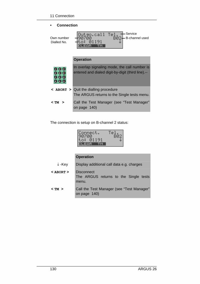
11 Connection
130 ARGUS 26
• Connection
The connection is setup on B-channel 2 status:
Operation
In overlap signaling mode, the call number isentered and dialed digit-by-digit (third line).--
< ABORT > Quit the dialling procedureThe ARGUS returns to the Single tests menu.
< TM > Call the Test Manager (see “Test Manager”on page 140)
Operation
↓ -Key Display additional call data e.g. charges
< ABORT > DisconnectThe ARGUS returns to the Single testsmenu.
< TM > Call the Test Manager (see “Test Manager”on page 140)
Own numberDialled No.
ServiceB-channel used

11 Connection
131ARGUS 26
• Display additional call data
If the ARGUS displays a ↓ on the right on the third line,additional information can be viewed by simply pressing abutton (τηε ↓−key) :
• Subaddress
The sub-address of the caller (second line) and thedialed sub-address will be displayed.
• User-User Information
• Display Information
• Type of number (T.o.n.)
• Numbering Plan (NP)
• Advice of charge
The up-to-date AOC information will be presented on thethird line of the display as it is received. With the < ↓>you can scroll through additional information (if there isany).
Operation
< ABORT > DisconnectThe ARGUS returns to the Single testsmenu.
< TM > Call the Test Manager (see “TestManager” on page 140)
↓ -Key Additional information will be shown in thedisplay.

11 Connection
132 ARGUS 26
If the charges are not given in units, rather directly ascurrency, the ARGUS will display the current charges incurrency.
If, in DSS1, the call charges are not provided inaccordance with the -ETS 300 182 standard, rather in theform of the information element DISPLAY (DSP), theDISPLAY message's character string will be displayed.
Procedure for an Incoming Call (ISDN)
An incoming call can be taken at any time even when a test(e.g. BERT) is in process (see “Simultaneously StartingSeveral Tests” on page 141). The ARGUS will signal an incoming call with an audible toneand a message on thedisplay.
The 16-digit call number (DDI) will be displayed in itsentirety, as long as the “Alerting mode” in the “Parameter”menu has been set to “manual” (see Chap. 16.2.3 Alertingmode page 174).
Operation
< ACCEPT >or
-Key
Accept the incoming call
< REJECT > Reject the incoming call
↓ -Key Additional information is available(optional: indicated by the ↓ on thedisplay) and can be displayed ( e.g.,SUB, UUS)-
The numberof
ServiceB-channel used
Own number

11 Connection
133ARGUS 26
On a P-MP access, you can use the Call acceptance (-see“Call Acceptance” on page 188) function to configure theARGUS to only signal incoming calls which are addressed tothe MSN that corresponds to your own call number. Thisfunction can only be used when your own call number hasbeen entered into the ARGUS’s speed-dialing memory (see“Saving Call Numbers” on page 218) and the incoming callhas a destination MSN.
After a call is taken, the followingdisplay will appear:
If an external handset has been connected (see“Handset” on page 211 ), the following will bedisplayed when the call is accepted:
Operation
< ABORT > Disconnect.Continue to the Single tests menu.
< TM > Call the Test Manager(see “Test Manager” on page 140 )
Operation
< INTERNAL
>
Switches to the internal handset(necessary in order to take a call, if noheadset is connected.)
< ABORT > DisconnectContinue to the Single tests menu
< TM > Call the Test Manager (see “Test Manager”on page 140)
A telephone connectionto the subscriber withthe call number02351907070 nowexists on B-channel 1.-
Switches to theinternal handset

11 Connection
134 ARGUS 26
Charge information in NT mode:
If the ARGUS is in NT mode, the ARGUS will – for incomingcalls – send advice of charges in accordance with DSS1 asunits and as currency (in Euro).

11 Connection
135ARGUS 26
11.2 Setting up an ISDN connection
To clear (disconnect) the connection: press< CLEAR> or the
-Key
When the ARGUS is clearing the connection or when it hasbeen disconnected, it will display the following:
The second line in the display will show the cause (see thetable below) of the disconnect.
In the third line, the ARGUS shows the location of the partythat initiated the disconnection or where the fault (causingthe disconnect) occurred.-
If the charges are sent at the end of the connection, thecharges will be displayed accordingly.
The connection has now been cleared-down and the B-channel is released.
The following causes are shown in clear text:
Operation
↓ -Key Display further information
< TM > Call the Test Manager (see “Test Manager”on page 140)
< CONT. > Continue to the Single tests menu
Cause Display Explanation255 Active clearing User actively initiated
the disconnection Long 0 Normal clearing Cause element with Long 0 is
mostly used by 1TR6
Cause

11 Connection
136 ARGUS 26
Other causes are not shown in clear text, rather as decimalcodes (see Appendix B and C).
01 Unalloc. number “No access under this call number” is signaled
16 Norm. clearing Normal disconnect 17 User busy The number called is busy 18 No user respond No answer from the number
called-19 Call.time XX Call time too long 21 Call reject The call is actively rejected28 Wrong number Wrong call number format or
call number is incomplete-31 Norm. clearing Unspecified “normal class”
(Dummy)34 No B-chan.avail. No circuit / B-channel
available 44 Req.chan.unavail Requested B-channel not
available 50 Req.fac.not subs Requested supplementary
service (facility) not subscribed
57 BC not authoriz. Requested bearer capability is not enabled
63 Srv./opt.n.avail Unspecified for “Service not available” or “Option not available”
69 Req.fac.not impl. Requested facility is not supported
88 Incompat. Objectives
Incompatible destination
102 Timer expired Error handling routine starteddue to time-out
111 Protocol error Unspecified for ”protocol error class”
127 Interworking err Unspecified for “interworkingclass”-
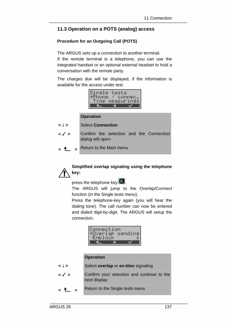
11 Connection
137ARGUS 26
11.3 Operation on a POTS (analog) access
Procedure for an Outgoing Call (POTS)
The ARGUS sets up a connection to another terminal.If the remote terminal is a telephone, you can use theintegrated handset or an optional external headset to hold aconversation with the remote party.
The charges due will be displayed, if the information isavailable for the access under test.
Simplified overlap signaling using the telephonekey:
press the telephone key . The ARGUS will jump to the Overlap/Connectfunction (in the Single tests menu). Press the telephone-key again (you will hear thedialing tone). The call number can now be enteredand dialed digit-by-digit. The ARGUS will setup theconnection.
Operation
< ↓ > Select Connection
< > Confirm the selection and the Connectiondialog will open-
< > Return to the Main menu
Operation
< ↓ > Select overlap or en-bloc signaling
< > Confirm your selection and continue to thenext display
< > Return to the Single tests menu
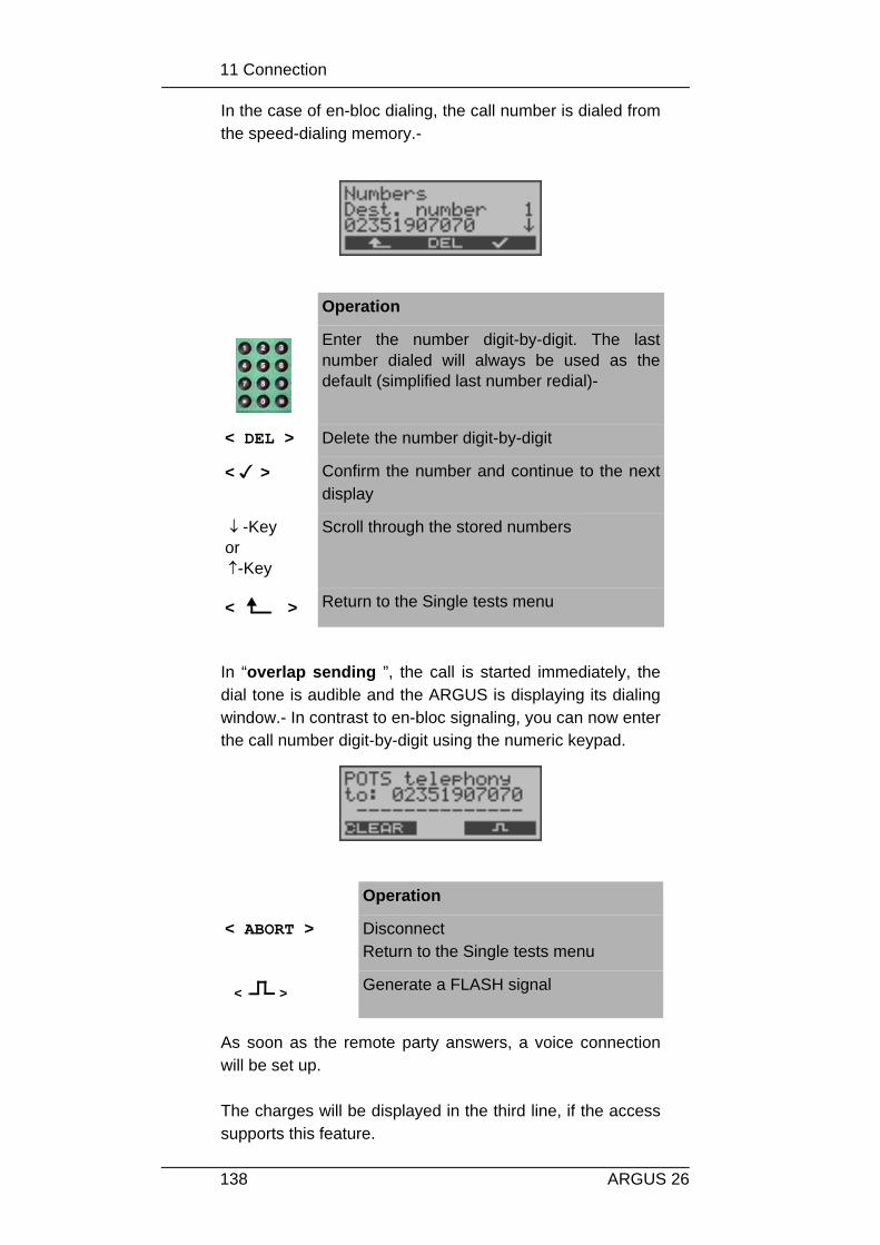
11 Connection
138 ARGUS 26
In the case of en-bloc dialing, the call number is dialed fromthe speed-dialing memory.-
In “overlap sending ”, the call is started immediately, thedial tone is audible and the ARGUS is displaying its dialingwindow.- In contrast to en-bloc signaling, you can now enterthe call number digit-by-digit using the numeric keypad.
As soon as the remote party answers, a voice connectionwill be set up.
The charges will be displayed in the third line, if the accesssupports this feature.
Operation
Enter the number digit-by-digit. The lastnumber dialed will always be used as thedefault (simplified last number redial)-
< DEL > Delete the number digit-by-digit
< > Confirm the number and continue to the nextdisplay
↓ -Keyor ↑-Key
Scroll through the stored numbers
< > Return to the Single tests menu
Operation
< ABORT > DisconnectReturn to the Single tests menu
< > Generate a FLASH signal

11 Connection
139ARGUS 26
Procedure for an Incoming Call (POTS)
The ARGUS signals an incoming call both audibly and onthe display.
If the access supports CLIP, the ARGUS will display thenumber of the caller on the second line (-see “POTS CLIP”on page 198).
After acceptingthe call:
Operation
< ACCEPT > or
-Key
Accept the incoming call
Operation
< ABORT> Disconnectand return to the Single tests menu
< > Generate a FLASH signal
No. of the caller

12 Test Manager
140 ARGUS 26
12 Test Manager
The ARGUS can simultaneously start several tests or“connections” fully independently of each other.A maximum of 31 simultaneous “connections” are possible.As an example, a BERT can be run at the same time thatyou make a phone call. The individual tests or “connections”use resources.
All of the tests that have been started will be administeredby the Test Manager. Using the Test Manager you can startnew tests, switch between tests running in parallel orterminate all of the tests that are currently running.
Calling the Test Manager in the Main menu:
If the ARGUS has currently opened the Single testsor Configuration menu or one of the Single testfunctions, the Test Manager can be opened usingthe 6-Key or via the < TM >softkey.
Operation
< ↓ > Select the Test Manager menu
< > Confirm your selection
< > Return to the status display
< ↓ > Select the desired menu item e.g. Start newone
< > confirm
< > Return to the Main menu

12 Test Manager
141ARGUS 26
12.1 Simultaneously Starting Several Tests
Starting a new test or connection during an existingconnection
The ARGUS has an existing connection (see Chap. 11.1Setting up an ISDN connection page 125). Open the TestManager (6-Key or < TM >).
Start another test, e.g. the bit error test from the Single tests/ Bit error test menu (see Chap. 10.3.1 BERT startwait page94). Similar to Chap. 6.6.5.1, the ARGUS will perform a biterror test independent of the currently existing connection.
Operation
< ↓ > Select the Start new one function
< > the ARGUS will jump to the status display
< > Returns to the existing connection
The ARGUS jumps to the Main menu fromwhich you can start other tests as usual.
Number of existingconnections

12 Test Manager
142 ARGUS 26
Test - aborting
If a test (or connection) is cancelled, the ARGUS will returnto the Test Manager if there are any other tests (orconnections) running in the background.
All of the existing connections (and/or tests) will bedisplayed by the Test Manager:
Operation
< TM > The ARGUS jumps to the Test Manager
< ERROR > Injecting an "artificially generated" bit error-
<ABORT > Cancels the bit error test and displays theBERT results. In the BERT results window,press the <TM> softkey to return to the TestManager.
Operation
< ↓ > Scrolls through all of the existing connectionsor tests.The ARGUS displays the B-channel used forthe currently selected test (in the example aBERT) in the first line.
< > The ARGUS will jump to the marked test.
marked test
The marked test will bestarted first
Number of existingconnections/tests
The B-channel used by themarked test

12 Test Manager
143ARGUS 26
Some tests use so many resources that they cannotbe run in every combination with other tests. In thiscase, the ARGUS will display the message “Test notpossible at this time”.
< > The ARGUS will return to the point fromwhich the Test Manager was called (e.g. to atest running in parallel). If this is notreasonable, because e.g. no other test isrunning, the ARGUS will return to the Mainmenu.
Test/Connection
Number of times thatthis test/connection canbe started at the sametime
It is possibleto change toanother test
Incoming call 30 Yes
Outgoing call 30 Yes
BERT 1 Yes
LOOP 2 Yes
Service Tests 1 No
Suppl.serv.test
1 No
Timemeasurement:Setting up call
1 No
Timemeasurement:B-channeldelay
1 No
Timemeasurement:Interchanneldelay
1 No
X.31 Test 1 No
CFInterrogation
1 No

12 Test Manager
144 ARGUS 26
Accepting an incoming call/connection when a test isrunning.
The ARGUS signals an incoming call with a correspondingmessage on the display and an audible signal (see Chap.11.1 Setting up an ISDN connection page 125). The incoming call can be accepted without influencing thecurrently running test. If either the B-channel loop or BERTwait function is active, the call will be acceptedautomatically.
The manner that multiple connections are handled isillustrated in the following example of an incoming call thatarrives during a BERT, but it is identical for all other tests.
The ARGUS is performing a bit error test as an incoming callis signaled on the display:
MSNInterrogation
1 No
Traffic Gen. 1 No
Auto. Test 1When the Auto. Test isrunning all of theresources are in use andno other tests orconnections are possible-
No
BRI level 1 No
BRI level,remote end
1 No
U voltage 1 No
U power 1 No
POTS voltage 1 No

12 Test Manager
145ARGUS 26
Operation
< REJECT >
Reject the incoming call The ARGUSreturns to the running test (in theexample: to the BERT)
< ACCEPT >
Accept the incoming call. The ARGUS willthen jump to the Connections dialog.The connection is active and in theforeground.-The BERT continues to runs in thebackground and can be viewed via theTest Manager (6-Key).-
6 -Key The ARGUS jumps to the Test Manager
Operation
< ↓ > Select the BERT outgoing
< > The ARGUS jumps to the BERT
< > The ARGUS will then return to the“Connections” dialog.

12 Test Manager
146 ARGUS 26
If available, the internal handset will be assigned tothe currently started (voice) connection.-
Only one speech channel can be active at a time.
The assignment of the handset to a givenconnection is also retained in the background.

12 Test Manager
147ARGUS 26
12.1.1 Switching Between Tests
First call the Test Manager.
12.1.2 Cancel all
First call the Test Manager.
Operation
< ↓ > Mark the test/connection that you wish toswitch to
< > The ARGUS will jump to the selected test.
< > The ARGUS will return to the point fromwhich the Test Manager was called
Operation
< ↓ > Select Cancel all
< > The ARGUS will cancel all of the currentlyrunning tests/connections and then return tothe Main menu.
< > The ARGUS will return to the point fromwhich the Test Manager was called
13 Automatic Test
148 ARGUS 26
13 Automatic Test
The ARGUS performs an automatic test series and displaysthe test results. With the special optional cable (RJ45 to Centronicsconnector), you can print out a simple test report on aCentronics printer.
The test results can also be saved on a PC (with the Intecsoftware WINplus or WINanalyse installed) and then beviewed and printed as a comprehensive test report.--
The ARGUS automatically performs the following sequenceof tests:
On a BRI or U-interface access(optional)(ARGUS in TE Mode)- Status- Level Measuring- Service Tests- BERT in an extended call to oneself- Suppl.serv.test- CF Interrogation- MSN Interrogation- X.31 test
On a PRI access(ARGUS in TE Mode)- Status- Service Tests- BERT in an extended call to oneself- Suppl.serv.test- CF Interrogation- X.31 test- Read the L1 counter and measurement time
On a BRI or U-interface permanent circuit (optional)- Status- Level Measuring- BERT in end-to-end mode (e.g. with a loopbox on the
remote end)
On a PRI permanent circuit
- Status- BERT in end-to-end mode (e.g. with a loopbox on the
remote end)- Read the L1 counter and measurement time

13 Automatic Test
149ARGUS 26
The test results and the time will be saved in the ARGUStogether with the date (assuming the exchange sent it viathe D-channel).-Additionally, settings such as your own plus a remote callnumber will also be saved.The test results are stored in non-volatile memory and arenot lost when the ARGUS is switched off.
The ARGUS saves the results of multiple test series(records 1,2,3...). .
Each function in the Automatic test menu refers to one of thetest series saved as a record.
Therefore, a window will open first showing a list of therecords saved.
Operation
< ↓ > Select Automatic Test Tests Menu
< > Confirm your selection
< > Return to the status display
< ↓ > Select record:Each data record (holding the results of asaved test) is identified by a sequential numberplus the date and time “Free” data recordshave only a number.

13 Automatic Test
150 ARGUS 26
If an automatic test sequence is started by pressing functionkey 4 instead of via the Automat.Tests menu, a data recordwill be selected automatically and the Automatic test willbegin immediately. The result will saved in the first data record that is free (e.g.No.3 when two test series are already saved).
If all of the records are used, the ARGUS will return to the“Autom. Test” menu and request permission to overwrite theoldest test results.
<NUMBER> The number of the access tested will be shownwith each of the saved records of test results, ifthe number was entered under own number inthe speed-dialing memory.(see “Saving Call Numbers” on page 218).
< > confirmA menu with various functions for processingthe selected data record will openautomatically.
< > Return to the Main menu

13 Automatic Test
151ARGUS 26
13.1 Starting the Automatic Test
Before running a BERT, check and, if necessary,modify the measurement time and error level(threshold) (see Chap. 16.3.1 BERT - duration page191).
During the test series, the first three lines in the display willreflect the Single test currently being run. If the test series iscanceled (< ABORT> softkey ), another menu will open:
Operation
< ↓ > Select Start
< > Confirm your selection
< > Return to the Auto.Test menu
Enter your Own numberOnly on accesses with the DSS1 protocol:also enter a remote call number
< > Confirm and the Select service window willopen.
< ↓ > Select service (will be used for thesuppl.serv.test)-
< > Start test

13 Automatic Test
152 ARGUS 26
In this menu, you have the option of either aborting theautomatic series of tests or skipping individual tests (e.g.service check).
Test - aborting
An automatic test series can be terminated before it isfinished:
If the automatic test is interrupted, the test resultsgathered up to this point will not be saved. Any “old” data stored under this data record numberfrom a prior test will be retained.
Operation
< ↓ > Select Interrupt test
< > Confirm that the test should be stopped
<ABORT > Continue the test series

13 Automatic Test
153ARGUS 26
Skipping individual testsA single test (e.g. BERT) can be skipped:
Resume Automatic Test
A test series, which was interrupted with <ABORT>, can beresumed. In this case, the interrupted single test (e.g. BERT)will be repeated.
Operation
< ↓ > Select Stop cur. test
< > The test currently being performed will beskipped (e.g. BERT) and the next test in theautomatic sequence will start.-
<ABORT > Resume Automatic Test
Operation
< ↓ > Select Continue test
< > In this case, the interrupted single test (e.g.BERT) will be repeated and the test seriesresumed.-
<ABORT > Resume Automatic Test

13 Automatic Test
154 ARGUS 26
13.2 Display Results
The ARGUS displays the result of the automatic test .
The results of the individual tests will be displayed in thefollowing order:-
For: BRI or U-interface PRI BRI or U-interface- Permanent
circuit- Status Status Status- Level measuring Service test Level
measuring- Service test BERT BERT- BERT Suppl.serv.test- Suppl.serv.test X.31 test - X.31 test CF Interrog- CF Interrog L1 counter and - MSN Interrog Measurement time
For: PRI permanent circuits- Status- BERT- L1 counter and
measurement time
Operation
< ↓ > Select Display result
< > Confirm your selection
< > Return to the Auto.Test menu
< CONT. > Continue to the next results window
< ABORT> Return to the Auto. Test No.x menu

13 Automatic Test
155ARGUS 26
The interpretation of the test results is described in theindividual sections (e.g. in Chapter 10.2 Service check page86) .
Operation
< ↓ > Scroll through the results of a single test
< CONT.> Jump to the results of the next single test
< ABORT> Return to the Auto.Test No.2 menu

13 Automatic Test
156 ARGUS 26
13.3 Test results – sending to a PC
To visualize and archive the test results on the PC, the datarecords can be transferred to the PC via the serial interfaceusing the included cable (connect the cable between theARGUS “L-Test” jack ---- PC’s serial interface).
Connect the ARGUS to your PC.
Procedure
Start ARGUS WINanalyse on the PC.-First select the data record, which should be transferred tothe PC (in the following example Test No.2) and then startthe transfer of data:
Operation
< ↓ > Select Test data to PC
< > Start transfer of data to PC
< > Return to the Auto.Test menu

13 Automatic Test
157ARGUS 26
13.4 Printing the test results (optional)
With a special (optional) cable, it is also possible to print asimplified test report on a Centronics printer.
Plug the matching end of the special cable into the L-Testjack on the ARGUS. Plug the Centronics connector into theprinter.
Select the data record that you wish to print (in the followingexample Test No.2).
While printing, the following will be shown on the display:
If an error occurs while printing, the ARGUS will show “Noreply” in the second line of the display; if the data istransferred properly “Transfer OK” will be displayed.-
Operation
< ↓ > Select Print data
< > Start printing
< > Return to the Auto.Test menu
Operation
< ABORT > Quit printing

13 Automatic Test
158 ARGUS 26
13.5 Deleting test results
The results of a test sequence can be deleted (Delete theresults of all test sequences: see “Reset” on page 220 ).Select the test sequence that you wish to delete (in theexample Test No.2).
Operation
< ↓ > Select Delete
< > The deletion will begin
< > Return to the Auto.Test menu

14 Voltage and level measurement
159ARGUS 26
14 Voltage and level measurement
14.1 Level measuring on a BRI access
• Level measurement – connected line
The ARGUS measures the level of the received usefulsignal. In TE mode, it also measures the phantom feed. Themeasurement will be updated continuously.
Operation
< ↓ > Select the Level measuring menu
< > Open the Level measuring menu
< > Return to the status display
Operation
< ↓ > Select the Connected line (remote end)
< > Start measurement
< > Return to the Main menu

14 Voltage and level measurement
160 ARGUS 26
Measurement results: 1. line: The level of the useful signal in volts. An
evaluation of the level follows:<< level is too low>> level is too highOK level is in order (0.75V +20%
-33%)__ no voltage
3. line: The level of the feed in volts. An evaluationof the level follows.Afterwards, the type of supply will bedisplayed: NORM normal feed (40V +4.25%
-13.75%)REV_ inverted phantom feedNONE no feed
• Level measurement other TE
In TE mode, the ARGUS will measure the level of a terminalconnected in parallel. In this case, the ARGUS is passive.
Layer 1 must be active on the terminal, whose level will bemeasured. The ARGUS updates its measurementcontinuously.
< NEW > Layer 1 will setup again to ensure a propermeasurement on a Layer 1 that is notpermanently active
< R>ON >or< R>OFF >
insert a 100Ω resistor.orremove a 100Ω resistor.
<ABORT > Return to the Level measuring menu
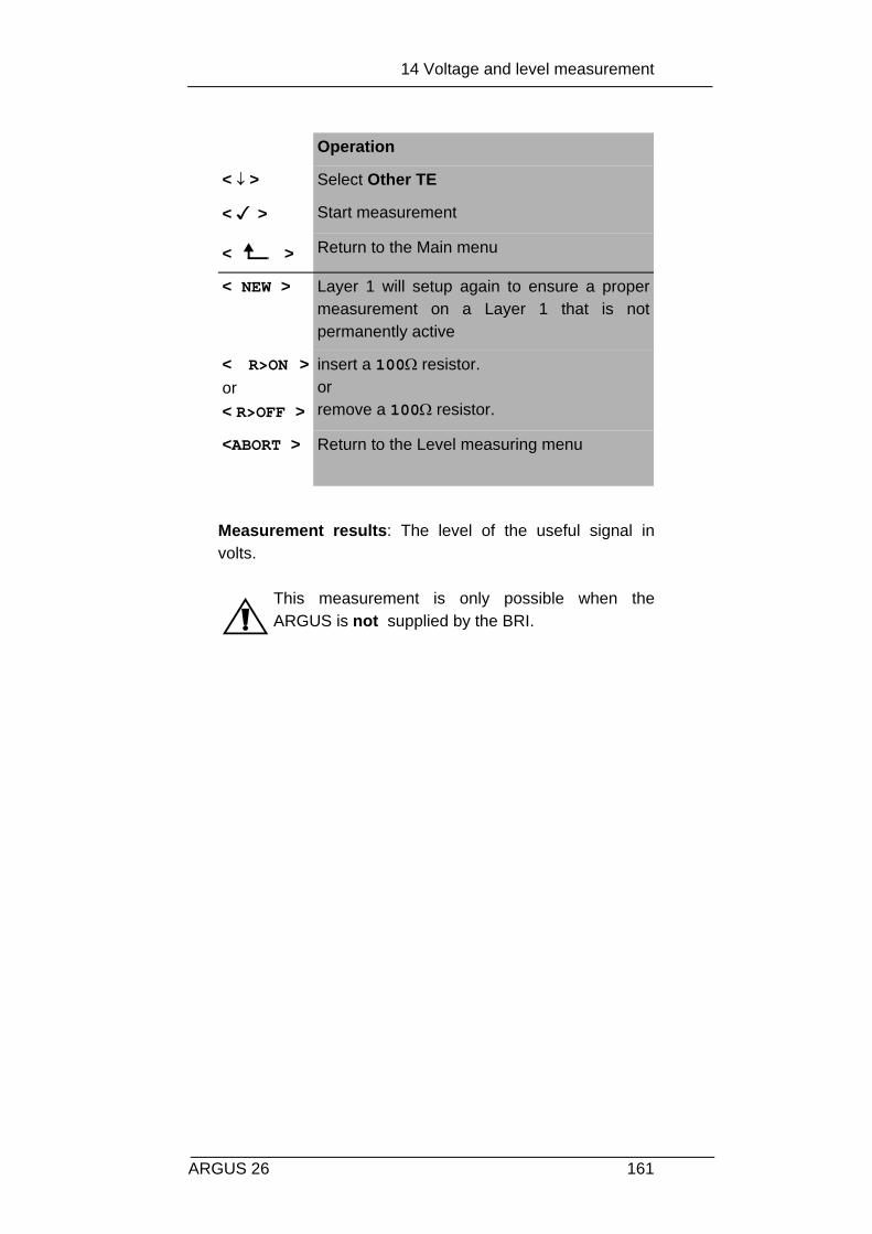
14 Voltage and level measurement
161ARGUS 26
Measurement results: The level of the useful signal involts.
This measurement is only possible when theARGUS is not supplied by the BRI.
Operation
< ↓ > Select Other TE
< > Start measurement
< > Return to the Main menu
< NEW > Layer 1 will setup again to ensure a propermeasurement on a Layer 1 that is notpermanently active
< R>ON >or< R>OFF >
insert a 100Ω resistor.orremove a 100Ω resistor.
<ABORT > Return to the Level measuring menu

14 Voltage and level measurement
162 ARGUS 26
14.2 Voltage measurement on a U-interface
• Measurement of feed voltage - U-interface (optional)
The ARGUS measures the level of the feed voltage. Themeasurement will be updated continuously.
Measurement results: The level of the supply in volts.
Operation
< ↓ > Select Voltage U
< > Start measurement
< > Return to the Main menu
<ABORT > Return to the Level measuring menu

14 Voltage and level measurement
163ARGUS 26
14.3 Voltage measurement on a POTS access
The ARGUS measures the voltage level in both the normalcase and when the line is “busy” (trunk line).
Measurement results:
1. line: The polarity of the analog line (2 wire)Red plug: aBlack plug: b
2. line: The normal voltage level in V3. line: The voltage level when the line is “busy” inV
The measurement will be updated continuously.
Operation
< ↓ > Select the Connected line (remote end)
< > Start measurement
< > Return to the Main menu
< NEW > Repeat measurement
< ABORT> Return to the Level measuring menu

15 L1 Status
164 ARGUS 26
15 L1 Status
15.1 The L1 status of a BRI access
The ARGUS displays in TE mode the current status of Layer1: which signal is received from the remote end (Rx) andwhich signal the ARGUS sends (Tx).
The ARGUS displays the status of Layer 1 or of the signal,which is being sent ( Info 0 .... Info 4).
Operation
< ↓ > Select the L1 status menu
< > Open the L1 status function
< > Return to the status display
< NEW > Layer 1 will be setup,if it is not already
<ABORT > Return to the Main menu
From the remoteend, the received signalFrom the ARGUS,

15 L1 Status
165ARGUS 26
15.2 The L1 status of a PRI access
The ARGUS displays the Layer 1 alarms and messages inseveral windows, which provide detailed informationregarding the state of the PRI access and the transmissionline (For further information, see the CCITT/ITU guidelinesG.703 and G.704).
The measurement time and all Layer 1 alarms andmessages are updated continuously.
On the first line, you will find the time (in minutes andseconds) that has elapsed since the ARGUS was initiallystarted or since it was last reset.
Operation
< ↓ > Scroll through the display
< X > The PRI relay for the Rx/Tx pin assignment willbe toggled to its other position, regardless ofthe state that it was in before. This function is only available with the L1 statusmenu, if there is currently no signal. The stateof the relay will remain unchanged when youclose the L1 status menu.Signal=means that Rx/Tx are normalSignal=means that Rx/Tx are inverted
<RESET> Reset the History function and all counters
<ABORT> Quits the function; the ARGUS will return to theMain menu

15 L1 Status
166 ARGUS 26
OK symbol: +Error symbol: -History symbol: ! this symbol means that regardless of
the current Status (+ or -) an error has occurred during the measurement time.
The meaning of the individual displays:
Signal: On its receiving-side, the ARGUS has thecorrect
signal sent from the remote end (access orterminal depending on the operation mode TEor NT simulation) -and indicates this by a + . IfRx and Tx are connected normally a "=" will beshown after the signal; in the event that they areinverted (swapped) a " X" will be displayed.
FAS: ( = Frame Alignment Signal)Indicates whether the ARGUS could correctlysynchronize with the incoming 2 Mbit datastream’s alternating frame identification word ormessage word and the, perhaps present,CRC4-superframe structure.-
CRC det: If CRC4-monitoring is active for the access orthe terminal
and the ARGUS is able to synchronize itself tothe CRC4 superframe, it will indicate this bydisplaying “CRC det +”. If “CRC det –” is displayed together with “Signal+” and “FAS +”, this indicates that no CRC4 isactive.To o prevent power up effects (transients), werecommend that you set the display and counterto a defined initial state with a RESET.
Code HDB3: Displays the transmission code used(currently fixed to HDB3)
noA-Bit: With the A-Bit, the remote end can indicatewhether the route on its receive-side is nolonger availablenoA-Bit + means A=0: Idle statenoA-Bit - means A=1: Return direction is notavailable

15 L1 Status
167ARGUS 26
noAIS: ( Alarm Indication Signal)AIS will be set if a component on thetransmission line determines that the signal theyhave received is faulty (e.g., in the event, thatthey lose frame synchronization) and afterwardsthey will send a Time –1 (=AIS).noAIS = + : No AIS occurred.
Sa5-Bit The Sa5-bit (Rx) sent by the ARGUS can(Rx ,Tx): be set in the Configuration menu
(see “Setting the Sa5 Bits” on page 179 )
Sa6-Bit The Sa6-bit (Rx) sent by the ARGUS can(Rx ,Tx): be set in the Configuration menu
(see “Setting the Sa6 Bits” on page 180 )
E-Bit: With the two E-Bits, E1 and E2, the remote endwill report any CRC4-errors that it finds on itsreceive side in the first or second submultiframe(the E-Bit will be set to 0)E-Bit11+ : if both E-Bits are set to 1, no erroroccurred E-Bit11+! : A CRC4-error was found (indicatedby the “!”), however the circuit is in largest partOK (see the E-Bit counter Ecnt or CRC4 errorcounter CRCErr)
Ecnt: The E-Bit counter counts the reported E-Biterrors individually; in other word, all the cases inwhich a faulty CRC4 submultiframe wasreceived (counts at a maximum of 1kHz).
CRC Err: The CRC4 error counter totals the number ofCRC4 submultiframes in which errors weredetected...-
CRC rel: Gives the CRC4 error rate, in other words, thenumber of faulty CRC4 frames relative to thetotal number of CRC4 frames received.
Code Err: Counter for the detected HDB3 transmissioncode errors-
Code rel: Transmission code - error rate
Frame Err: Counter for faulty 2Mbit frames

16 Configuration
168 ARGUS 26
16 Configuration
The ARGUS can be configured to suit your specialrequirements. All of the default settings can be restored withthe RESET function.
The currently active settings will be marked in the displaywith an *.
Operation
< ↓ > Select Configuration
< > Open the Configuration menu
< > Return to the status display
currentlyactive Setting

16 Configuration
169ARGUS 26
16.1 Trace mode
The ARGUS passes the recorded D-channel data to theconnected PC or saves it in the internal FLASH memory.
The Trace mode setting is only saved temporarily.In other words, Trace mode is always off when theARGUS is first switched on.
With the setting Trace mode “ On, PC “, the ARGUS remainsactive and sends all of its own D-channel messages andthose that it receives from the network to the PC.-
When the trace mode is active, the LED labeled “Trace” willbe on continuously. If the ARGUS cannot send the data tothe PC without errors, the LED will flash at 5Hz (5 times persec).
In the Trace mode “On, Recording”, the ARGUS remainsactive, but saves the D-channel messages in the internal
Operation
< ↓ > Select the Trace mode
< > Open the Trace mode selection dialog
< > Return to the Main menu
< ↓ > Select the Trace mode
< > Accept the Trace mode setting and returnto the Configuration menu
< > Return to the Configuration menu withoutmaking any changes

16 Configuration
170 ARGUS 26
Flash memory. If the ARGUS has been configured with thissetting, the LED will flash slowly (once per sec) whentracing.-
The D-channel data saved in the Flash memory canbe transferred to the PC in the “Recorder” mode(see “BRI / PRI Recorder” on page 58).

16 Configuration
171ARGUS 26
16.2 Configuration: ISDN
16.2.1 Layer 1 permanent
(only on a BRI access)
Layer 1 (L1) on a BRI connection in NT mode ispermanently active.
Operation
< ↓ > Select the ISDN configuration menu
< > Open the ISDN configuration menu
< > Return to the Main menu
Operation
< ↓ > Select L1 permanent?
< > Open the L1 permanent? selection dialog
< > Return to the Configuration menu
< ↓ > Select the desired L1 mode.
< > Accept setting and return to the ISDNconfiguration menu

16 Configuration
172 ARGUS 26
< > Return to the ISDN configuration menuwithout making any changes

16 Configuration
173ARGUS 26
16.2.2 Select the D-channel protocol
Besides automatic protocol recognition (Setting: Automatic),the ARGUS also allows you to manually set the Layer 3 D-channel protocol. The ARGUS will save the protocol settingand will use this protocol the next time that it is switched on.-.
Operation
< ↓ > Select the Protocol
< > Open the Protocol selection dialog
< > Return to the Configuration menu
< ↓ > Select the Layer 3 protocol
< > Accept protocol setting and return to theISDN configuration menu
< > Return to ISDN configuration menu withoutchanging the protocol

16 Configuration
174 ARGUS 26
16.2.3 Alerting mode
For an incoming call on a BRI point- to-point access, theARGUS will display either the access number alone withoutextension or the complete number with extension.
If you select Manual, the ARGUS will display the extension(An incoming call will be signaled. The ARGUS will send theLayer 3 message “Alert” when it accepts the call. The digitsof the extension that have been sent by this point will bedisplayed.).
With the Manual setting, an incoming call must beanswered within 20 seconds or it will be lost.Furthermore, you should not that the remotesubscriber will not hear a ringing tone.
If you select Automatic, the ARGUS will only display theaccess number without extension or, depending on theconfiguration of the access in the exchange, it may notdisplay the number called at all.
Operation
< ↓ > Select the Alerting mode
< > Open the Alerting mode selection dialog
< > Return to the Configuration menu
< ↓ > Select the desired alerting mode.
< > Accept setting and return to the ISDNconfiguration menu
< > Return to the ISDN configuration menuwithout making any changes

16 Configuration
175ARGUS 26
16.2.4 Clock mode
When the ARGUS is operated on a BRI or PRI access, youcan specify where the clock is generated (regardless ofwhether the operation mode is TE or NT).
You can either specify that the ARGUS generates the clock(is Master) or that it is the slave of a clock generated at theother end.
The default setting is Master for NT simulations or Slave forTE simulations and permanent circuits.
This setting will not be saved permanently, ratheronly applies for the current measurement. When the ARGUS is switched off, the setting is lost.
Operation
< ↓ > Select the Clock mode
< > Open the Clock mode selection dialog
< > Return to the Configuration menu
< ↓ > Select the desired clock mode
< > Accept clock mode setting and return to theISDN configuration menu-
< > Return to the ISDN configuration menuwithout making any changes

16 Configuration
176 ARGUS 26
16.2.5 BRI termination
Independent of the operation mode (TE or NT), aterminating resistor can be switched in for the BRI access.
No terminating resistor will be switched in when the Argus isin TE simulation mode or on a permanent circuit.- In the NTsimulation mode, the terminating resistors are switched on. .
This setting will not be saved permanently When theARGUS is switched off, the setting is lost.
Operation
< ↓ > Select BRI termination
< > Open BRI termination selection dialog
< > Return to the Configuration menu
< ↓ > Select setting
< > Accept setting and return to the ISDNconfiguration menu-
< > Return to the ISDN configuration menuwithout making any changes

16 Configuration
177ARGUS 26
16.2.6 PRI termination
Depending on the transmission technique (75 Ohm coaxial-cable or twisted-pair cable with an impedance of 120Ohms) used, the PRI termination resistor must be selectedaccordingly.
The default setting is country-specific and corresponds tothe system most common in the respective country:
Germany, Austria, England,Netherlands, France, ...
120 Ohm
Spain, Italy, Greece, ... 75 Ohm
Operation
< ↓ > Select PRI termination
< > Open the PRI termination selection dialog
< > Return to the Configuration menu
< ↓ > Select the value of the terminating resistor
< > Accept setting and return to the ISDNconfiguration menu-
< > Return to the ISDN configuration menuwithout making any changes
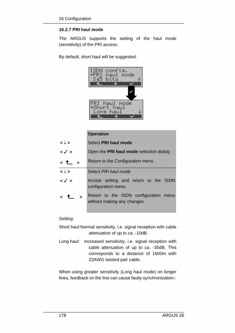
16 Configuration
178 ARGUS 26
16.2.7 PRI haul mode
The ARGUS supports the setting of the haul mode(sensitivity) of the PRI access.
By default, short haul will be suggested.
Setting:
Short haul:Normal sensitivity, i.e. signal reception with cableattenuation of up to ca. -10dB.
Long haul: Increased sensitivity, i.e. signal reception withcable attenuation of up to ca. -35dB. Thiscorresponds to a distance of 1600m with22AWG twisted pair cable.
When using greater sensitivity (Long haul mode) on longerlines, feedback on the line can cause faulty synchronization.-
Operation
< ↓ > Select PRI haul mode
< > Open the PRI haul mode selection dialog
< > Return to the Configuration menu
< ↓ > Select PRI haul mode
< > Accept setting and return to the ISDNconfiguration menu
< > Return to the ISDN configuration menuwithout making any changes

16 Configuration
179ARGUS 26
16.2.8 Setting the Sa5 Bits
The ARGUS can set the Sa5 bits on a PRI access.By default, the Sa5 bits are set to 0000.
Options for the Sa5 bits:
The Sa5 bits have no significance between anNTPM and a PBX system.
This setting will not be saved permanently If theARGUS is switched off, the setting will be lost.
Operation
< ↓ > Select Sa5 bits
< > Open the Sa5 bits selection dialog
< > Return to the Configuration menu
< ↓ > Select Sa5 bits
< > Accept setting and return to the ISDNconfiguration menu
< > Return to the ISDN configuration menuwithout making any changes
Sa5-Coding
Meaning(Network -->Terminal)
Meaning(Terminal -->Network)
0000 Direction code Acknowledgment forloop command
1111 ----- Direction code

16 Configuration
180 ARGUS 26
16.2.9 Setting the Sa6 Bits
The ARGUS can set the Sa6 bits on a PRI access.By default, they are set to 0000.
Options for the Sa6 bits:
Operation
< ↓ > Select Sa6 bits
< > Open the Sa6 bits selection dialog
< > Return to the Configuration menu
< ↓ > Select the desired Sa6 bits
< > Accept setting and return to the ISDNconfiguration menu
< > Return to the ISDN configuration menuwithout making any changes
Sa6Coding
Meaning(Network --> Terminal)
Meaning(Terminal -->Network) *.*
0000 Setting for normal operation(default)
Setting fornormaloperation, idle(default)

16 Configuration
181ARGUS 26
The Sa6 bits have no significance between anNTPM and a PBX system.
This setting will not be saved permanently When theARGUS is switched off, the setting is lost.
1010 Switches a loop in theNTPM. In the permanentcircuit mode, a BERT canthen be performed using theloop setup there.- Important:The ARGUS must be set to“Permanent switch-” even ifit is a dialup access!
________
1111 Switches a loop in theLEPM. In the permanentcircuit mode, a BERT canthen be performed using theloop setup there.- Important:The ARGUS must be set to“Permanent switch-” even ifit is a dialup access!
AIS on U2an ofthe NTPM

16 Configuration
182 ARGUS 26
16.2.10 Setting the A-Bit
Using the ARGUS, you can set the A-Bit on a PRI access.By default, A=0 (automatic).
This setting will not be saved permanentlyWhen the ARGUS is switched off, the setting is lost.
Operation
< ↓ > Select A bit
< > Open the A bit selection dialog
< > Return to the Configuration menu
< ↓ > Select the desired setting
< > Accept setting and return to the ISDNconfiguration menu
< > Return to the ISDN configuration menuwithout making any changes

16 Configuration
183ARGUS 26
16.2.11 CRC4 mode
CRC4 monitoring can be switched on or off manually.By default, CRC4 is set to automatic.
This setting will not be saved permanentlyWhen the ARGUS is switched off, the setting is lost.
Operation
< ↓ > Select CRC4 mode
< > Open the CRC4 mode selection dialog
< > Return to the Configuration menu
< ↓ > Select the desired setting
< > Accept setting and return to the ISDNconfiguration menu
< > Return to the ISDN configuration menuwithout making any changes

16 Configuration
184 ARGUS 26
16.2.12 Call parameter
Different parameters can be set for (ISDN) calls generatedon both the network-side (ARGUS in NT mode) and on theuser-side (ARGUS in TE mode):
• Type Of Number (TON) for the CGN (=CGPN) or CDN (=CDPN) element of a SETUP signal
• The Numbering Plan (NP) for the CGN (=CGPN) or CDN (=CDPN) element of a SETUP signal
Operation
< ↓ > Select Call parameter
< > Open the Call parameter selection dialog
< > Return to the Configuration menu
< ↓ > Select the desired call parameter:Network-side: Net CGN TON /Net CDN TONUser-side: User CGN TON /User CDN TONSet the Type Of Number (TON) for the CGN orCDN element of a SETUP signal
Network-side: Net CGN NP /Net CDN NPUser-side: User CGN NP /User CDN NPSet the Numbering Plan (NP) for the CGN orCDN element of a SETUP signal
< > Open the selection dialog
< > Return to the ISDN config. menu

16 Configuration
185ARGUS 26
Possible settings:
For TON: unknown, international, national, network spec.,subscriber, abbreviated.
For NP: unknown, ISDN/telephony, data, telex, nationalstand., private
Operation
< ↓ > Select the desired setting
< > Accept settings and return to the Callparameter menu
< > Return to the Call parameter menu withoutmaking any changes

16 Configuration
186 ARGUS 26
16.2.13 Services
Up to three user specific services ( BCAP, HLC and LLC )can be entered into and stored in the ARGUS inhexadecimal.
Operation
< ↓ > Select Service
< > Open the Service menu
< > Return to the Configuration menu
< ↓ > Scroll to desired User spec.
< > A dialog will open in which the info-elementsBCAP, HLC and LLC of the user specificservice must be entered in hexadecimal.
< > Return to the ISDN configuration menu
Operation
Enter the BCAP info-element using thekeypad (0....9) and

16 Configuration
187ARGUS 26
This setting will be saved permanently.
< A..F > To enter the hexadecimal numbers A,B...F(e.g. to enter a B press the softkey <A..F>twice. When you press <OK> the cursormove to the next entry point.)
< DEL > Delete the digit before the cursor
< ↓ > To scroll to the next info-element (HLC andLLC)
<ABORT > Return to the Services menu

16 Configuration
188 ARGUS 26
16.2.14 Call Acceptance
In TE mode on a P-MP access (P-P access), the ARGUSwill signal either all incoming calls or just those calls whosedestination address matches the MSN of the access undertest.-
The function is only available, when your own call numberhas been saved in the speed-dialling memory under “ownnumber” (see Chap. 16.6 Saving Call Numbers page 218)and the incoming call has a destination MSN (DDI). .
The default setting is all MSN/DDI.
This setting will be saved permanently.
Operation
< ↓ > Select Call acceptance
< > Open the Call acceptance menu
< > Return to the Configuration menu
< ↓ > Select the desired setting:only own MSN/DDI:The ARGUS signals theincoming call, if its destination MSN/DDImatches your “own” number.- all MSN/DDI: The ARGUS signals all calls
< > Accept setting and return to the ISDNconfiguration menu-
< > Return to the ISDN configuration menuwithout making any changes

16 Configuration
189ARGUS 26
16.2.15 Voice coding
There are two options for coding voice data in a B-channel:• A-Law• µ-Law .The default setting is A-Law.
Operation
< ↓ > Select Voice coding
< > Open the Voice coding menu
< > Return to the Configuration menu
< ↓ > Select the desired setting
< > Accept setting and return to the ISDNconfiguration menu-
< > Return to the ISDN configuration menuwithout making any changes

16 Configuration
190 ARGUS 26
16.2.16 DTMF / Keypad
During a ISDN connection, the keypad can be used to sendeither DTMF tones or keypad elements.By default, this parameter is set to DTMF. .
Operation
< ↓ > Select DTMF / Keypad
< > Open the DTMF / Keypad menu
< > Return to the Configuration menu
< ↓ > Select the desired setting
< > Accept setting and return to the ISDNconfiguration menu-
< > Return to the ISDN configuration menuwithout making any changes

16 Configuration
191ARGUS 26
16.3 Configuration: BERT
16.3.1 BERT - duration
The default setting for the duration of the bit error rate test is1 minute. The measurement time may be set to a limitedperiod of no more than 99:59 (99 hours and 59 minutes) oran unlimited time (by entering 00:00).
If the BERT is set to an unlimited measurement time,the test will not stop automatically, rather it must bestopped by the user (see Chap. 10.3.1 page 94).
Operation
< ↓ > Select the BERT configuration menu
< > Open the BERT configuration menu
< > Return to the Main menu
Operation
< ↓ > Select BERT time
< > Open the BERT time menu
< > Return to the Configuration menu

16 Configuration
192 ARGUS 26
Enter the desired duration of the BERT
< DEL > Delete the digit before the cursor
< > Accept setting and return to the BERTconfiguration menu-
< ABORT> Return to the BERT configuration menu withoutchanging the setting.

16 Configuration
193ARGUS 26
16.3.2 BERT - Setting the Error level
The default threshold (error level) is 10-06. That means that,in the event that the bit error rate is less than 10-06 (oneerror in 106 = 1,000,000 sent bits) , the bit error test will beevaluated as OK.
If the bit error rate is greater than the error level value, theARGUS will display NO. This parameter can be set to anyvalue from 01 (= 10-01 ) to 99 ( = 10-99 ).
Operation
< ↓ > Select clock mode
< > Open the Error level menu
< > Return to the Configuration menu
Enter desired value for the error level:01 (= 10-01) to 99 (= 10-99)
< DEL > Delete the digit before the cursor
< > Accept settings and return to the BERTconfiguration menu
< ABORT> Return to the BERT configuration menuwithout changing the setting.

16 Configuration
194 ARGUS 26
16.3.3 HRX value
Here the HRX value is set in % (Hypothetical ReferenceConnections ITU-T G.821):
Operation
< ↓ > Select HRX value
< > Open the HRX value menu
< > Return to the Configuration menu
Enter the desired HRX valueValues from 0 to 100 %
< DEL > Delete the digit before the cursor
< > Accept the HRX value and return to the BERTconfiguration menu.
< ABORT> Return to the BERT configuration menu withoutchanging the HRX value.

16 Configuration
195ARGUS 26
16.3.4 Selecting the BERT bit pattern
There are two predefined bit patterns available: 211-1, 215-1, 220-1, 223-1 normal and inverted as well asconstant 0 and constant 1.Additionally, it is also possible to enter a 16 bit long patternof your choice in binary.-
The default pattern is 215-1.
If the "user defined" bit pattern is selected, a dialog will openin which the 16 bit long bit pattern must be entered in binary. In the BERT, the ARGUS will either send this bit patterncyclically or compare it with the received bit pattern.
Operation
< ↓ > Select bit pattern
< > Open the Protocol menu
< > Return to the Configuration menu
< ↓ > Select the desired bit pattern
< > Accept setting and return to the BERTconfiguration menu-
< > Return to the BERT configuration menuwithout changing the setting.

16 Configuration
196 ARGUS 26
.Operation
Enter the desired bit pattern in binary.The digit selected by the cursor can bedirectly overwritten.
< > Moves the cursor to the left.
< > Accept the settings and return to the BERTconfiguration menu. The bit pattern entered will be storedpermanently.
<ABORT > Return to the BERT configuration menuwithout changing the bit pattern.

16 Configuration
197ARGUS 26
16.4 Configuration: POTS
16.4.1 POTS dial mode
On a POTS access, there are two methods available fordialing (DTMF and pulse dialing):-
Operation
< ↓ > Select the POTS configuration menu
< > Open the POTS configuration menu
< > Return to the Main menu
Operation
< ↓ > Select POTS dial mode
< > Open the POTS dial mode menu
< > Return to the Configuration menu
< ↓ > Mark the desired dialing mode.
< > Confirm your entry and return to the POTSconfiguration menu
< > Return to the POTS configuration menuwithout changing the dialing mode

16 Configuration
198 ARGUS 26
16.4.2 POTS CLIP
You can choose from two different methods for transferringthe call number on a POTS access:
• FSK CLIP via a method similar to a modem:for Germany as well as some other parts of
Europe• DTMF CLIP via DTMF:
for Scandinavia and the NetherlandsThe ARGUS will automatically detect that aCLIP was sent using DTMF with the polarityreversal and will set itself accordingly -(e.g. Netherlands).
Operation
< ↓ > Select POTS CLIP mode
< > Open the POTS CLIP mode menu
< > Return to the Configuration menu
< ↓ > Select the desired CLIP method
< > Accept setting and return to the POTSconfiguration menu-
< > Return to the POTS configuration menuwithout making any changes

16 Configuration
199ARGUS 26
16.4.3 AOC pulse
On a POTS access, the country-specific AOC pulse can beselected (12 or 16 kHz).
Operation
< ↓ > Select the AOC pulse
< > Open AOC pulse menu
< > Return to the Configuration menu
< ↓ > Select the AOC pulse
< > Accept setting and return to the POTSconfiguration menu
< > Return to the POTS configuration menuwithout making any changes

16 Configuration
200 ARGUS 26
16.4.4 DTMF parameter
The ARGUS can set the parameters Level, Duration andInterval of the DTMF signals that are generated duringPOTS operation.
Setting the DTMF level:
The default value is -3dB. The level can take a valuebetween -21dB and +12dB and can be raised or lowered by3dB.
Operation
< ↓ > Select DTMF parameter
< > Open the DTMF parameter menu
< > Return to the Configuration menu
Operation
< ↓ > Select the level
< > Open the Level menu
< > Return to the POTS configuration menu.

16 Configuration
201ARGUS 26
Setting the DTMF time:
The default setting is 80ms. The duration of the signal cantake a value between 40ms and 1s. The duration can beraised or lowered using the arrow keys as follows:
In the range 40...200ms in 10ms incrementsIn the range 200...300ms in 20ms incrementsIn the range 300...1000ms in 100ms increments
When the upper limit is reached (1000ms), the softkey < ↑ >will automatically change to a < ↓ > and vice versa when thelower limit (40ms) is reached.
< ↓ > or ↓ -Key
To lower the level by 3dB
↑-Key To raise the level by 3dB
< > Accept settings and return to the DTMFparameter submenu
< ABORT > Return to the DTMF parameter submenuwithout making the changes
Operation
< ↓ > Select the Time
< > Open the Time submenu
< > Return to the POTS configuration menu.
< ↓ > or↓ -Key
Lower the duration
↑-Key Increase the duration

16 Configuration
202 ARGUS 26
Setting the interval between two DTMF characters:
The default value is 80ms. The interval between two DTMFcharacters can take a value between 40ms and 1s. Theinterval can be raised or lowered by using the arrow keys asfollows:-
In the range 40...200ms in 10ms incrementsIn the range 200...300ms in 20ms incrementsIn the range 300...1000ms in 100ms increments
When the upper limit is reached (1000ms), the softkey < ↑ >will automatically change to a < ↓ > and vice versa when thelower limit (40ms) is reached.
< > Accept settings and return to the DTMFparameter submenu
< ABORT> Return to the DTMF parameter submenuwithout making the changes
Operation
< ↓ > Select the DTMF interval
< > Open the DTMF interval submenu
< > Return to the POTS configuration menu.
< ↓ > or↓ -Key
Lower the DTMF interval
↑ -Key Raise the DTMF interval

16 Configuration
203ARGUS 26
Restore the defaults:
The following defaults can be restored at any time:- Level = -3 dB- Time = 80 ms- Interval = 80 ms
< > Accept settings and return to the DTMFparameter submenu
< ABORT> Return to the DTMF parameter submenuwithout making the changes
Operation
< ↓ > Select Reset to default
< > You will be asked whether you are sure.
< > Return to the POTS configuration menu.
< YES > Reset to default settings and return to theDTMF parameter menu
< NO > Return to the DTMF parameter menu withoutresetting to the default settings

16 Configuration
204 ARGUS 26
16.4.5 FLASH time
With this selection, you can set the length of a flash whenoperating on a POTS. This function is required in order to use the special featuresof a PBX.The FLASH time can take a value between 40ms and 1s.- Itcan be raised or lowered using the arrow keys as follows:
In the range 40...200ms in 10ms incrementsIn the range 200...300ms in 20ms incrementsIn the range 300...1000ms in 100ms increments
When the upper limit is reached (1000ms), the softkey < ↑ >will automatically change to a < ↓ > and vice versa when thelower limit (40ms) is reached.
Operation
< ↓ > Select FLASH time
< > Select the FLASH time menu
< > Return to the POTS menu
< ↓ > or↓ -Key
Reduce FLASH time
↑-Key Increase FLASH time
< > Accept settings and return to the POTSmenu
< ABORT> Return to the POTS menu without makingthe change

16 Configuration
205ARGUS 26
16.5 Configuration: ARGUS
16.5.1 Selecting the menu language
Operation
< ↓ > Select the ARGUS configuration menu.
< > Open the ARGUS configuration menu.
< > Return to the Main menu
Operation
< ↓ > Selecting the Menu language
< > Open the Menu language menu
< > Return to the Configuration menu
< ↓ > Select the desired language
< > Confirm your selection and return to theARGUS configuration menu
< > Return to the ARGUS configuration menuwithout changing the setting.

16 Configuration
206 ARGUS 26
16.5.2 Setting the display contrast
The contrast of the ARGUS display can be adjusted to suitthe individual user. The contrast can be adjusted in 16steps.In the third line, the display shows a vertical arrow, whichindicates the current setting on a scale from "low to highcontrast".
Operation
< ↓ > Select LCD contrast
< > Open the LCD contrast menu
< > Return to the Configuration menu
↓ -Key Decrease contrast
↑ -Key Increase contrast
< > Change the LCD contrast and return to theARGUS configuration menu.
<ABORT > Return to the ARGUS configuration menuwithout changing the setting.

16 Configuration
207ARGUS 26
16.5.3 Enter date / time
Enter the date and time. The ARGUS will use these twovalues on the D-channel in NT mode and in the automatictest-.
The entered time will be continuously updated by theARGUS’s real time clock as long as the power is notswitched off.
When the power is switched off (the ARGUS switched offwithout batteries), the clock will run a few more weeks on itsinternal supply. If the backup supply is exhausted, the timewill be undefined and must be set again.
Operation
< ↓ > Select the Date / Time
< > Open the Date / time menu
< > Return to the Configuration menu
Enter the desired date
↓ -Key
↑ -Key
The cursor moves to the left
The cursor moves to the right
Enter the desired time
< DEL > Delete the digit before the cursor
< > Accept setting and return to the BERTconfiguration menu-
< ABORT> Return to the ARGUS configuration menuwithout making the changes

16 Configuration
208 ARGUS 26
16.5.4 Printer
This function is used to set the printer options.- The default isARGUS EPSON LQ.
If you wish to use a printer that is not compatible with eitherthe HP-Laserjet or the EPSON LQ, select the ESCsequence setting.
An entry mask will open in which you can enter an ESC-sequence character-by-character, which will permit theoptimum adaptation to your printer.
Up to 9 different ESC sequences can be entered and savedin the EEPROM in the ARGUS so that these will still beavailable after the ARGUS has been switched off and thenback on.-
Does not work with what are known as Windowsprinters.
Operation
< ↓ > Select Printer
< > Open the Printer menu
< > Return to the Configuration menu
< ↓ > Select desired printer
< > Accept setting and return to the ARGUSconfiguration menu-
< > Return to the ARGUS configuration menuwithout changing the setting.

16 Configuration
209ARGUS 26
Operation
Enter the ESC sequence (see theinformation from the manufacturer of yourprinter) in decimal format. The charactercodes are each separated by a “#”.
< DEL > Delete the digit before the cursor
< > Save the entered ESC sequence inEEPROM. The display is setup for the entryof the next ESC sequence.
< EXIT > Return to the Configuration menu

16 Configuration
210 ARGUS 26
16.5.5 Baud rate
There is a selection of baud rates available for use whenconnecting the ARGUS to a PC.The default setting is 57600 baud.
Operation
< ↓ > Select Baud rate
< > Open the Baud rate menu
< > Return to the Configuration menu
< ↓ > Select the desired setting
< > Confirm the selection and return to theARGUS configuration menu
< > Return to the ARGUS configuration menuwithout changing the setting.

16 Configuration
211ARGUS 26
16.5.6 Handset
The ARGUS makes a distinction between the integratedhandset and an external headset:
With the softkey, an existing connection can be switchedback and forth between an external headset and theintegrated handset (-see “Setting up an ISDN connection” onpage 125).
Operation
< ↓ > Select the Handset
< > Open the Handset menu
< > Return to the Configuration menu
< ↓ > Select the desired handset
< > Accept setting and return to the ARGUSconfiguration menu-
< > Return to the ARGUS configuration menuwithout changing the setting.

16 Configuration
212 ARGUS 26
16.5.7 Alarm bell
The ARGUS signals with an alarm in a variety of situations,e.g. when a bit error occurs in a BERT. The alarm bells canbe switched off.
This setting is not lost when the ARGUS is switched off andback on again.
Operation
< ↓ > Select Alarm bell
< > Open the Alarm bell menu
< > Return to the Configuration menu
< ↓ > Select the desired setting
< > Accept setting and return to the ARGUSconfiguration menu-
< > Return to the ARGUS configuration menuwithout changing the setting.
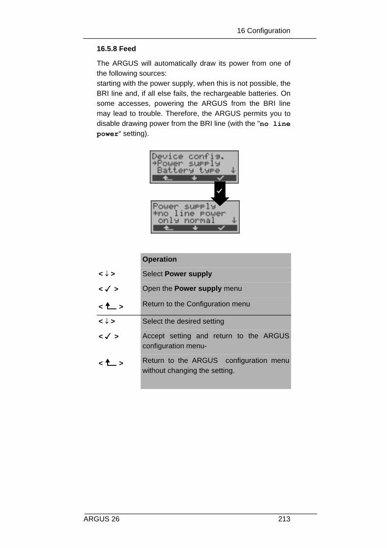
16 Configuration
213ARGUS 26
16.5.8 Feed
The ARGUS will automatically draw its power from one ofthe following sources:starting with the power supply, when this is not possible, theBRI line and, if all else fails, the rechargeable batteries. Onsome accesses, powering the ARGUS from the BRI linemay lead to trouble. Therefore, the ARGUS permits you todisable drawing power from the BRI line (with the "no linepower“ setting).
Operation
< ↓ > Select Power supply
< > Open the Power supply menu
< > Return to the Configuration menu
< ↓ > Select the desired setting
< > Accept setting and return to the ARGUSconfiguration menu-
< > Return to the ARGUS configuration menuwithout changing the setting.

16 Configuration
214 ARGUS 26
16.5.9 Battery type
Specify whether the ARGUS will be operated with batteriesor accumulators (rechargeable batteries).- If you select"Accu", the ARGUS will display the current level of charge ofthe accumulators (rechargeable batteries).
If you select "Battery", the "Accu servicing" function in theARGUS configuration menu will be disabled.
Operation
< ↓ > Select Battery type
< > Open the Battery type menu
< > Return to the Configuration menu
< ↓ > Select the desired setting
< > Accept setting and return to the ARGUSconfiguration menu-
< > Return to the ARGUS configuration menuwithout changing the setting.

16 Configuration
215ARGUS 26
16.5.10 Accu servicing
The ARGUS will display the current charge of theaccumulators.As soon as the power supply is connected, the accumulatorsin the ARGUS can be completely discharged or immediately(without being first discharged) recharged. The dischargeprocedure takes up to 6 hours. The ARGUS willautomatically begin recharging the accumulators after abreak of about 30 minutes (depending on the capacity of theaccumulators, it can take up to 7 hours to recharge them).
Discharging the accumulators:
Operation
< ↓ > Select Accu servicing
< > Open the Accu servicing menu
< > Return to the Configuration menu
< ↓ > Select the desired settingConnect the power supply!
< > Start the charging or discharging process.The ARGUS will then jump to the ARGUS configuration menu
< > Return to the ARGUS configuration menuwithout starting the charging or dischargingprocess
Accumulatorstate
Displayof thevoltage
State ofdischarge

16 Configuration
216 ARGUS 26
Charging the accumulators:
Displayof thevoltage
Level ofcharge
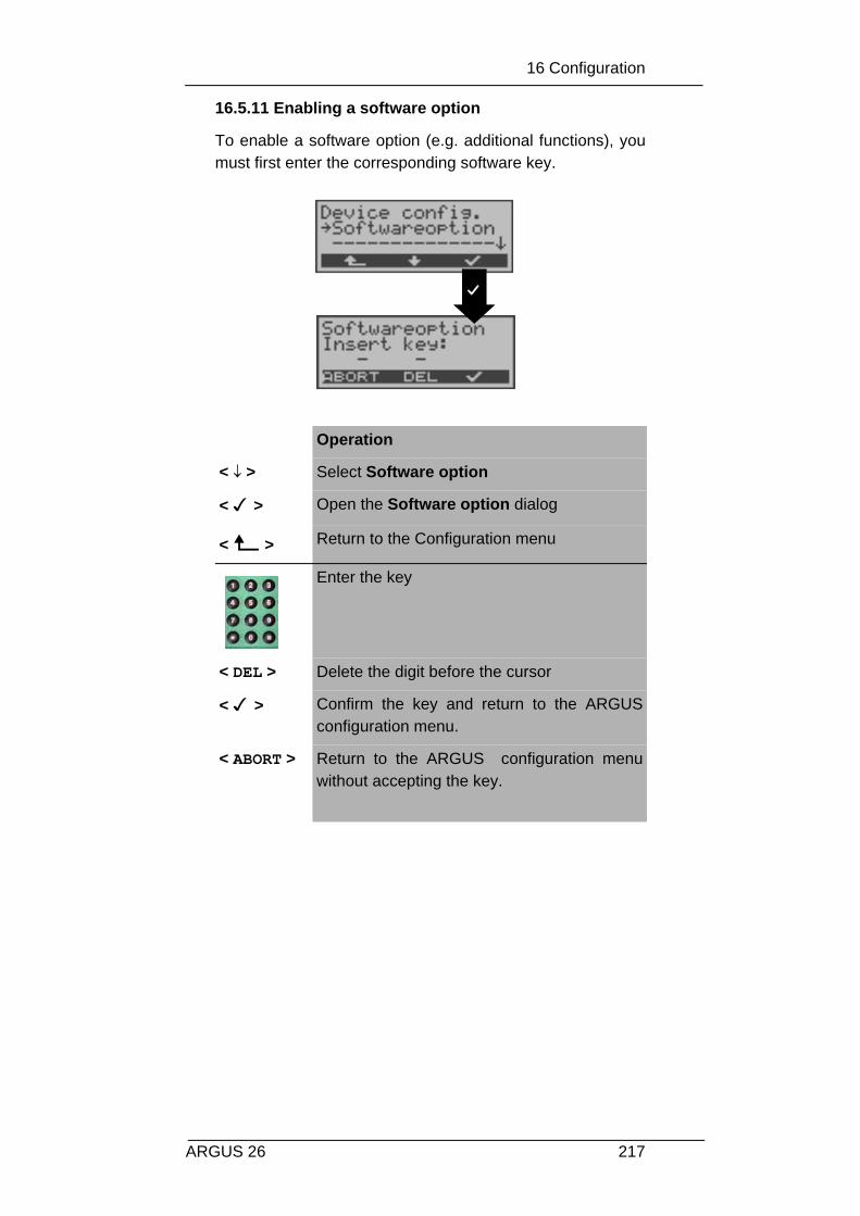
16 Configuration
217ARGUS 26
16.5.11 Enabling a software option
To enable a software option (e.g. additional functions), youmust first enter the corresponding software key.
Operation
< ↓ > Select Software option
< > Open the Software option dialog
< > Return to the Configuration menu
Enter the key
< DEL > Delete the digit before the cursor
< > Confirm the key and return to the ARGUSconfiguration menu.
< ABORT > Return to the ARGUS configuration menuwithout accepting the key.

16 Configuration
218 ARGUS 26
16.6 Saving Call Numbers
Ten call numbers with a maximum of 24-places can beentered in the speed-dialing memory.
The first number must be the own call number ofthe access under test (this is especially important forthe automatic Service test).
In the Remote No.1-8 memory locations, you can saveremote call numbers. In the memory location X.31 testnumber , the ARGUS expects the entry of the X.25 accessnumber for the X.31 test (see Chap. 10.4 page 103).o
Operation
< ↓ > Select Numbers
< > The Call number memory will open
< > Return to the Main menu
Enter the desired numberThe first number must be the own callnumber of the access under test.
↓ -Key Scroll to the next speed-dialing memory andenter the next number
< > Save call numbers. The dialog is setup forentry of the next call number.
< DEL > Delete the digit before the cursor
< > Return to the Configuration menu

16 Configuration
219ARGUS 26
When entering a call number with an extension (operation ofthe ARGUS on a PBX access), observe the following:The extension is separated from the access number by a #.
For outgoing calls, the ARGUS uses the entire call number(without #) as the number called (CDPN or DAD) and, for thecalling number (DSS1-CGPN or 1TR6-OAD), only thenumber after the #, in other words the extension. A "#" at thebeginning of a call number is treated as a valid character.
example:02351/9970-45 is entered as 023519970#45
If the “# “ is at the end of a number, when thenumber is later dialed it will be done without CGPNor OAD. This is important for some PBXs.

16 Configuration
220 ARGUS 26
16.7 Reset
The ARGUS will reset all of the settings to their defaultvalues.
The speed-dialing memory and the results of all ofthe automatic tests will be deleted.
The following settings are possible:
DefaultBERT time 1 minBERT error level 10-06
BERT bit pattern 1015-1BERT-HRX 15%Bit pattern “freely-
defined“
0000000000000000
PRI terminating
resistance
120 Ohm only for PRI
PRI haul mode SHORT HAUL only for PRISa5 bits 0000 only for PRISa6 bits 0000 only for PRIAlerting mode AutomaticCall acceptance all MSN/DDIL1 permanent? No only for BRI
NTClock mode For NT, Master
For TE, SlaveDTMF / Keypad DTMFPOTS dialing mode DTMFPOTS CLIP FSKPOTS AOC pulse 16 kHzPOTS FLASH time 80 msecDTMF parameter -3dB/80ms/80msMenu language Depends on country
(national variant)LCD contrast Average valueHeadset InternalPrinter EPSON LQESC sequence (Printer) noneBaud rate 57.600Alarm bell Off

16 Configuration
221ARGUS 26
Call numbers 0-9 All memory locationsempty
Auto Test results All memory locationsempty
Operation
< ↓ > Select Reset
< > Call up the security query
< > Return to the Main menu
< YES > Reset all settings,the ARGUS will then return to theConfiguration menu
<ABORT > Return to the Configuration menu withoutresetting the parameters.

17 Testing Features with the Keypad
222 ARGUS 26
17 Testing Features with the Keypad
This feature is only relevant for a BRI access!Some network operators do not support the standard DSS1features, rather they expect the user to control the networkvia so-called keypad command sequences.
In these cases, the desired facility is usually activated byentering a series of characters and then sending thesecharacters within a DSS1-specific protocol element. Theseso-called Keypad-Elements are imbedded in a SETUPmessage.
An outgoing call containing a keypad message is placedfrom the ARGUS by pressing the -Key.
To distinguish the call from a normal call, the first charactersent is the '#'. Each step is acknowledged either acoustically(handset) or via special protocol elements (cause). Thesecauses are displayed by the ARGUS.
To simplify the use of these functions, you can use theARGUS’s speed-dialing memory.
An example for an application:
Speed-dial number 0 4711 own number of theaccess under test
Speed-dial number 1 124527 tel. no. of own companySpeed-dial number 2 #*67# Code for activating CFB
Speed-dial number 3 ##67# Code for deactivatingCFB-
Speed-dial number 4 #*#67# Code for querying CFB(interrogation)
Speed-dial number 5 #*#21# Code for querying CFU(interrogation)
Speed-dial number 6 #*#61# Code for queryingCFNR(interrogation)
Speed-dial number 7 freeSpeed-dial number 8 freeSpeed-dial number 9 free

18 Connection for a PRI network
223ARGUS 26
18 Connection for a PRI network
Since there is no commonly accepted standard for theconnections in the 2 Mbit sector, you will be confronted withdifferent forms of connectors depending on the type ofterminal and the network termination used.
The ARGUS changes the connector pin assignmentsautomatically in accordance with the mode, TE or NT. Additionally, it is also possible to change the pinassignments manually in the L1-Status menu.
18.1 Connector Pin Assignments on the ARGUS
In TE mode, the ARGUS sends on lines 4 and 5, in NT-Mode on 1 and 2 (see illustration). An adapter cable, whichis suitable for the respective ISDN network/system, can beconnected using the RJ45-RJ45 adapter.-
1245
PIN PIN Function
NT TE1 1 Tx Rx8 2 Tx Rx2 4 Rx Tx7 5 Rx Tx
PRI-access
12
78
ARGUS RJ45connector
RJ45connector

18 Connection for a PRI network
224 ARGUS 26
18.2 Connection to DTAG NTPM
An optional RJ45-to-splitting-plug adapter cable is availableto permit connecting the ARGUS to the test jack on the frontof the NTPM from “Deutsche Telekom AG (DTAG)”.
18.3 The ARGUS 26 as Terminal
Use the RJ45 coupling to connect the RJ45-to-splitting-plugcable to the ARGUS access cable. First switch the ARGUSON and afterwards plug the ARGUS into the NTPM. Once you have selected the TE simulation mode, theARGUS will serve as a PRI terminal.
12
3
45
6
a b
Splitting plug pin assignment: The ARGUS in TE Mode1b Receive NT (Rx)2b Receive NT (Rx)5b Send NT (Tx)6b Send NT (Tx)
The ARGUS in NT ModePIN Function1a Send TE (Rx)2a Send TE (Rx)5a Receive TE (Tx)6a Receive TE (Tx)Rear view
of the soldercontacts

19 Appendix
225ARGUS 26
19 Appendix
A) Acronyms 3PTY Three party service /
Three party conferenceAl Action IndicatorAOC Advice of ChargeAOC-D Advice of Charge
Charging information during the call andat the end of the call
AOC-E Advice of ChargeCharging informationat the end of the call
AWS Call Forwarding (Anrufweiterschaltung) BC Bearer CapabilityBER Basic Encoding Rules / Bit Error RateBERT Bit Error Rate TestCALL PROC CALL PROCeeding message CCBS Completion of Calls to Busy SubscriberCCNR Call Complete No Response
Automatic Callback if the called party didnot answer
CD Call DeflectionCDPN CalleD Party NumberCF Call ForwardingCFB Call Forwarding Busy
Forward calls when busy CFNR Call Forwarding No Reply
Forward calls when no answerCFU Call Forwarding Unconditional
Forward all calls CGPN CallinG Party NumberCLIP Calling Line Identification Presentation
Display caller’s numberCLIR Calling Line Identification Restriction
Suppress display of the caller’s number COLP Connected Line Identification Presentation
Display the number of the party -calledCOLR Connected Line Identification Restriction
Suppress the display of the number of theparty with whom one is connected
CONN CONNect Message

19 Appendix
226 ARGUS 26
CONN ACK CONNect ACKnowledge MessageCR Call ReferenceCT Call TransferCUG Closed User GroupCW Call Waiting
Call waitingDAD Destination Address (1TR6)DDI Direct Dialling In
Direct dialling in to an extension on a PBX-DISC DISConnect MessageDM Supplementary services (Dienstmerkmal)DTMF Dual Tone Multi FrequencyEAZ Terminal Ident. No.
(Endgeräteauswahlziffer - 1TR6)ECT Explicit Call Transfer
Call transfer or directed call forwardingE-DSS1 European Digital Subscriber Signalling
System Number 1GBG Closed user group (CUG) (Geschlossene
Benutzer Gruppe)HLC High Layer CompatibilityHOLD Call Hold
HoldISDN Integrated Services Digital Network INFO INFOrmation MessageLAPD Link Access Procedure for D-channels
channelsLCN Logical channel number
Channel number in X.25LLC Low Layer CompatibilityMCID Malicious Call IdentificationMSN Multiple Subscriber NumberNSF Network Specific FacilitiesNT Network TerminationOAD Origination Address (1TR6)PD Protocol DiscriminatorREL RELease MessageREL ACK RELease ACKnowledge MessageREL COMPL RELease COMPLete MessageSCI Sending Complete IndicationSIN Service Indicator (1TR6)SUB Sub-addressing / Sub-addressing is
possible

19 Appendix
227ARGUS 26
SUSP SUSPend Message TE TErminal, Terminal EquipmentTEI Terminal Endpoint IdentifierTP Terminal Portability
Moving the terminal on the bus UUS User-to-User Signalling
Transfer of user data

19 Appendix
228 ARGUS 26
B) CAUSE-Messages – DSS1 Protocol
Dec. Cause Description01 Unallocated (unassigned) number No access under this call
number-
02 No route to specified transit network-
Transit network not reachable
03 No route to destination Wrong route or routing error
06 Channel unacceptable B-channel for the sending system not acceptable
07 Call awarded and being delivered in an established channel
Call awarded and connected in an already existing channel (e.g., X.25 SVC)
16 Normal call clearing Normal disconnect
17 User busy The number called is busy
18 No user responding No terminal equipment answered (Timer NT303 / NT310 time-out)
19 No answer from user (user alerted) Call time too long
21 Call rejected Call rejected (active)
22 Number changed Call number has been changed
26 Non-selected user clearing Incoming call not awarded to this terminal
27 Destination out of order Destination / access out of order
28 Invalid number format (address incomplete)
Wrong call number format or call number incomplete
29 Facility rejected The facility is not offered
30 Response to STATUS ENQUIRY Response to status enquiry
31 Normal, unspecified Unspecified for“normal class” (Dummy)
34 No circuit / channelavailable
No circuit / B-channel available -
38 Network out of order Network not operational
41 Temporary failure Network is temporarily not operational
42 Switching equipmentcongestion
Switching equipment is overloaded-
43 Access informationdiscarded
Access information could not be transferred
44 Requested circuit / channel not available
Requested circuit / B-channel is not available
47 Resources unavailable, unspecified Unspecified for “resource unavailable class” (Dummy)
49 Quality of serviceunavailable
The requested quality of service is not available-
50 Requested facility not subscribed Requested service attribute is not subscribed
57 Bearer capability not authorized The requested bearer capability is not enabled
58 Bearer capability not presently available
The requested bearer capabilityis not currently available

19 Appendix
229ARGUS 26
63 Service or option not available “Service unspecified or option notavailable class” (Dummy)
65 Bearer capability not implemented Bearer capability is not supported
66 Channel type not implemented Channel type is not supported
69 Requested facility not implemented Requested facility is not supported
70 Only restricted digital information bearer capability is available
Only limited bearer capability isavailable
79 Service or option not implemented, service unspecified or option not implementedclass” (Dummy)
Unspecified
81 Invalid call reference value Invalid call reference value
82 Identified Channel does not exist Requested channel is invalid
83 A suspended call exists, but this call identity does not
The call identity entered is the wrong one for the parked call
84 Call identity in use The call identity is already in use
85 No call suspended No call has been parked
86 Call having the requested call identity has been cleared-
The parked call has been cleared
88 Incompatible destination Incompatible destination
91 Invalid transit network selection Invalid format for the transit network identifier-
95 Invalid message, unspecified Unspecified for “Invalidmessage class” (Dummy)
96 Mandatory information element is missing
Mandatory information element is missing
97 Message type non-existent or not implemented
This type of message is in this phase not permitted, not defined or not supported
98 Message not compatible with call state or message type non-existent or not implemented
The content of the message is inthis phase not permitted, notdefined -or not supported
99 Information element non-existent or not implemented
The content of the information element is in this phase not permitted, not defined or not supported
100 Invalid information element con-tents
Invalid content in information element
101 Message not compatible with call state
Message not valid in this phase
102 Recovery on timer expired Error handling routine started due to time-out
111 Protocol error, unspecified Unspecified for “protocol error class” (Dummy)
127 Interworking, unspecified Unspecified for “interworking class” (Dummy)

19 Appendix
230 ARGUS 26
C) CAUSE-Messages – 1TR6 Protocol
Dec. Cause Description01 Invalid call reference value Invalid call reference value
03 Bearer service notimplemented
The service is not available in the central office or at another location in the network or the service has not been subscribed.
07 Call identity does not exist Unknown call identity
08 Call identity in use Call identity is already assignedto a “suspended” connection.
10 No channel available No further B-channel is free on the subscriber's access. (only significant locally)
16 Requested facility notimplemented
The entered FAC-Code is unknown in this network.
17 Requested facility notsubscribed
The requested facility is not available, because the initiating or the remote subscriber is not authorized.
32 Outgoing calls barred Outgoing calls are not possible due to the barring
33 User access busy If the sum of the number of free B-channels, the number of occupiedB-channels, the number of awardedB-channels and the number of calls without B-channel assignment equals four, new incoming calls will be cleared from the network. The calling subscriber receives a DISC with the cause “user access busy”(= first busy) and a busy signal.
34 Negative CUG comparison Connection not possible due to negative CUG comparison
35 Non-existent CUG This CUG (GBG) does not exist
37 Communication link as SPV not permitted
A connection is not possible, since for example, the RFNR-test was negative
53 Destination not obtainable A connection cannot be made due to a wrong destination, service or supplementary services.
56 Number changed Subscriber-B’s call number has changed.
57 Out of order The remote terminal is not ready.
58 No user responding No terminal has answered the incoming SETUP or the subscriber call was disconnected, it is assumed that someone is present (Time-out for ringing T3AA).-
59 User busy Subscriber-B is busy
61 Incoming calls barred Subscriber-B has blocked incoming calls or the requested service is not supported by -Subscriber-B.

19 Appendix
231ARGUS 26
62 Call rejected To Subscriber-A:The requested connection is actively rejected by Subscriber-B (by sending a DISC as answer to the incoming SETUP).- Another terminal is in the setup phase with the incoming call: The call has already been accepted by another terminal on the bus.
89 Network congestion Network congested, e.g., switching equipment congestion, no conference set free, ...
90 Remote user initiated Rejected or disconnected by remote end (subscriber or exchange).
112 Local procedure error Sent in a RELDisconnect due to local errors (e.g., not valid messages or parameters, time-out, ...).Sent in a SUSP REJDue to another already active supplementary service, the connection may not be “suspended”.Sent in a RES REJThere is no “suspended” connection. Sent in a FAC REJNo further supplementary service request is possible, since there is still one being -processed or the supplementary service requested is not available in the current state of the connection.
113 Remote procedure error Caused by error atremote end.
114 Remote user suspended Connection at the remote end is in the “hold” or “suspend” state.
115 Remote user resumed Connection at the remote end is no longer in the “hold” or “suspend” or “conference” state.
127 User Info discarded locally The message USER INFO is rejected locally. The cause is given in the message CON CON.Length entry (=0)Normal disconnect (e.g., in REL as answer to a DISC from subscriber or a change of service in a DISC): Command to the terminal to release the B-channel.

19 Appendix
232 ARGUS 26
D) ARGUS Error Messages
FaultNumber
FaultClass
Cause.
Description
0 E Network The network is not in a statedefined for DSS1 or 1TR6. Itmay be that this state is normalfor a PBX.-
1 to 127 B,C,D,E Network DSS1 or 1TR6 causes
150 E ARGUS An error occurred during thesupplementary service test.Frequent cause: no responsefrom network
152 B ARGUS The CF-Test was started with the wrong own number..
153 E ARGUS no HOLD is available, but HOLD is required to test the supplementary service (ECT, 3pty)
154 E ARGUS CLIR or COLR could not be tested, since CLIP or COLP is not available
161 B ARGUS The party called did not answer within the prescribed time (approx.10 sec)
162 B ARGUS A call was setup to a remotesubscriber, instead of beingsetup – as was expected – toyour own number.
163 E ARGUS The Auto-Test could not setup a connection and therefore the AOC/D supplementary service could not be tested.
170 ARGUS During the Suppl.services test, a call came in without a B-channel (call waiting). Therefore, it was not possible to accept the call and test.
199 B ARGUS A call number was entered.
200 ARGUS Internal error
201 A ARGUS Network did not confirm acceptance of the call (CONN sent, no CONN_ACK received from network)

19 Appendix
233ARGUS 26
X.31 Test – Error messages
204 A ARGUS - Layer 2 connection was cleared-down
- No response to SETUP (call setup)
- Layer 2 connection could not be setup
205 A ARGUS Reestablish the Layer 2Connection
206 ARGUS The selected B-channel isalready busy.
210 A ARGUS No response to theclear-down ( REL sent, noREL_CMP/REL_ACK receivedfromnetwork)
220 A ARGUS Remote end signaled that it is inState 0.
245 E ARGUS Keypad sent via ESC, but noresponse was received fromnetwork
250 E ARGUS FACility was sent, but noresponse was received fromnetwork
X.31 Causes
0 to 255 Network See ISO 8208: 1987(E)Table 5- Coding of the clearing cause field in clear indication packets, page 35
257 ARGUS no response from network(for a CALL-REQUEST or CLEAR-REQUEST)
258 ARGUS Unexpected or wrong answer from network(no CALL-CONNECTED or CLEAR-INDICATION as response to a CALL-REQUEST)
259 ARGUS The network has indicated in a DIAGNOSTIC message that the logical channel is invalid. Origin: No (=1) or a wrong LCN was set.
512 ARGUS It was not possible to determine an internal or external cause.Origin: Layer 2 could not be setup or remote end does not support X.31
65535 ARGUS X.31 Layer 3 test was not performed. The error can only occur in a test log.-

19 Appendix
234 ARGUS 26
X.31 Diagnostic (only for a cause less than 256)0 to 255 Network See ISO 8208: 1987(E)
Figure 14A page 121Figure 14B page 123 et seq.And/orCCITT Recommendation X.25, Annex E

19 Appendix
235ARGUS 26
E) Package Contents
Included in the package are:
- ARGUS
- 1.2 V Mignon AA accumulators
- BRI connecting cable
- PRI connecting cable
- 9V plug-in power supply
- TAE adapter
- RJ45-RJ45 adapter
- Shock-absorbing PVC jacket
- Cable for POTS and U-interface accesses
- User’s Guide
- WINanalyse CD
- Serial cable Type P2A3
- USB Adapter
- Registration
- ARGUS carrying case with strap