Embed Size (px)
Citation preview
V548
5-56
1-00
03/
08
ARGUS smoke detector© Merten2005V5485-561-0003/08
ARGUS smoke detectorOperating instructions
GB
– Sealing pin for ARGUS smoke detector (Art. no. MTN547000)
You can use sealing pins to see whether the smoke de-tector is manipulated.– System relay flush-mounted for ARGUS smoke detec-
tor (Art. no. MTN548001)The system relay flush-mounted controls external alarm devices.
¼ DANGERRisk of fatal injury from electrical currentThe device may only be installed and connected by skilled electricians. Observe the regulations valid in the country of use.
½ CAUTION• Do not paint the smoke detector!• The loud warning tone can damage your hear-
ing (protect your ears when performing the functional test).
• Smoke detectors do not extinguish a fire!• Smoke detectors detect smoke, but no flames
or, heat!• The power must be supplied to the smoke de-
tector via mains voltage (230 V). The battery supplies the smoke detector in case of tempo-rary mains voltage failure.
• The smoke detector only works with a function-ing, correctly connected and inserted battery. Functioning without battery is not possible!
• Do not use rechargeable batteries or power packs!
• The smoke detector monitors a specific area around where it has been installed and not nec-essarily other rooms or other floors!
ARGUS smoke detector 230 VArt. no. MTN5475..
ARGUS smoke detector Connect 230 VArt. no. MTN5485..
Accessories
For your safety
½ DANGERSmoke fumes are poisonous and can quickly lead to a loss of consciousness. In the event of fire, in-form everyone in the household (smoke will not wake people up, children tend to hide when in a panic) and leave the building immediately. If there is a lot of smoke, crawl along the floor. Do not ex-pose yourself to unnecessary danger. Inform the fire brigade (WHO, WHERE, WHAT)! - Your local fire brigade is happy to advise you.
| Think about how you can prevent fires and what to do in case of a fire (escape plan, assembly point, location of fire extinguishers, etc.).
The ARGUS smoke detector 230 V/Connect 230 V (re-ferred to below as the smoke detector) is a mains-pow-ered smoke detector with backup battery for early detection of smouldering fires and open fires with smoke building-up indoor.The green LED of a functional smoke detector glows green, and the red LED flashes every 40 seconds.The green LED shows that the 230 V power supply has been applied. If the 230 V supply fails, the green LED goes out and the battery takes over supplying the smoke detector.If the battery is not supplying enough power, a tone will sound every 40 seconds to supplement the flashing red LED. The smoke detector will continue to function for an-other 30 days.
½ CAUTIONIf you are away for longer than 30 days, you will not hear the warning tone. Therefore, perform a functional test directly after you return.
If the alarm persists for more than five seconds, the radio module will activate all other smoke detectors equipped with a radio module in the range and they will also sound the alarm.The detector which detected the smoke will transmit the alarm signal for at least 60 seconds and until it no longer detects smoke. A receiving detector will check for an alarm signal every 50 seconds. If no alarm signal comes from the transmitting detector, the receiving detector will also stop the alar.
| When you combine a radio smoke detector net-work with a wire smoke alarm network, there may only be one smoke detector with active radio op-eration in the wire smoke detector network!
Getting to know the smoke detector
| Make sure that everyone in the building is familiar with the signals of the smoke detector!
The following LED and tone signals show the depend-end status of the smoke detector:Smoke alarm
Normal operation
Battery empty
Defect of the smoke detector
Smoke detector signals
...........
...........
...........40 s 40 s
~ 230 V
...........
...........
40 s 40 s
...........
...........
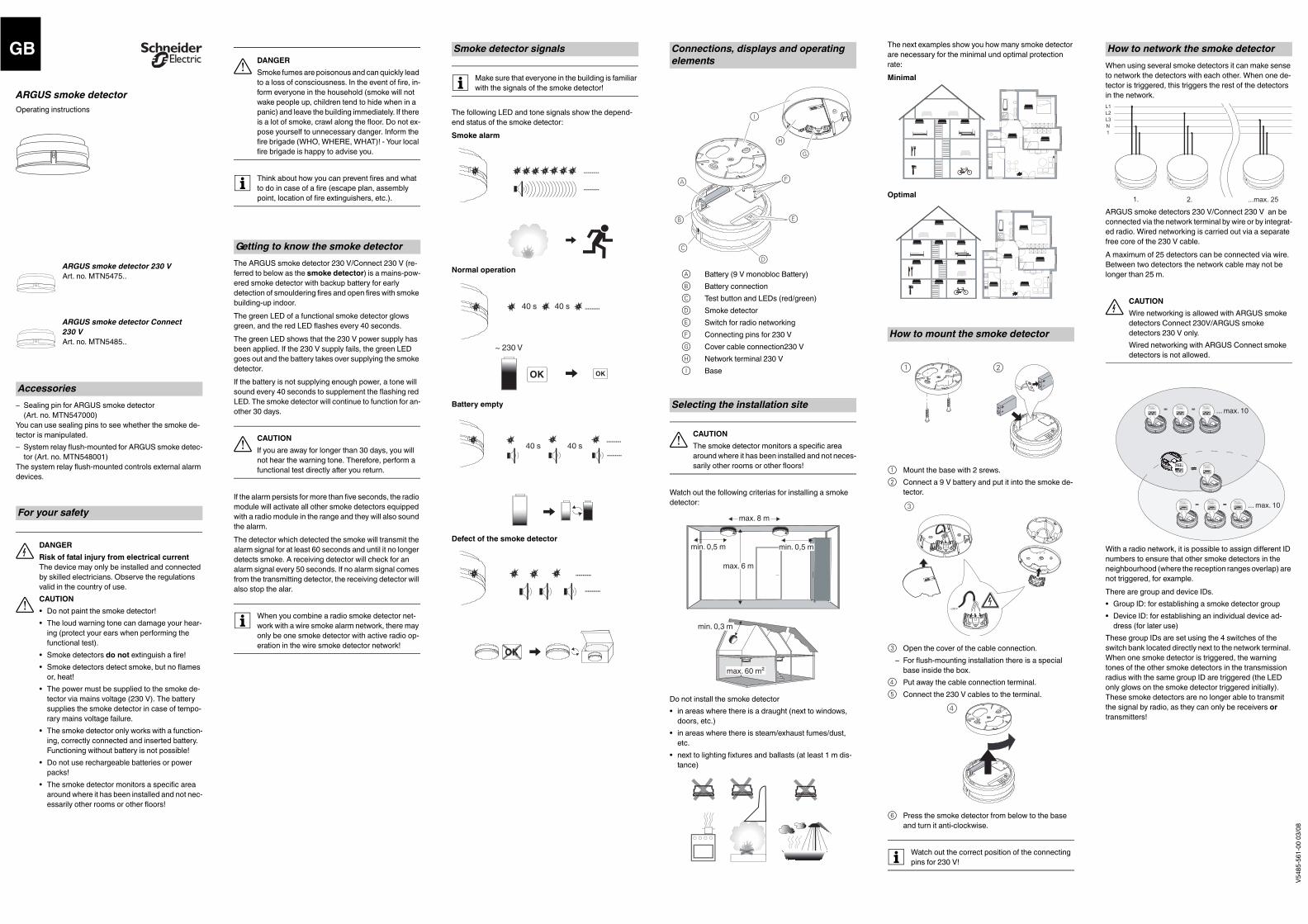
½ CAUTIONThe smoke detector monitors a specific area around where it has been installed and not neces-sarily other rooms or other floors!
Watch out the following criterias for installing a smoke detector:
Do not install the smoke detector• in areas where there is a draught (next to windows,
doors, etc.)• in areas where there is steam/exhaust fumes/dust,
etc.• next to lighting fixtures and ballasts (at least 1 m dis-
tance)
Connections, displays and operating elements
ABCDEFGHI
Battery (9 V monobloc Battery)Battery connectionTest button and LEDs (red/green)Smoke detectorSwitch for radio networkingConnecting pins for 230 VCover cable connection230 VNetwork terminal 230 VBase
Selecting the installation site
EB
DC
A F
I
HG
max. 60 m²
min. 0,3 m
max. 8 m
min. 0,5 m min. 0,5 m
max. 6 m
The next examples show you how many smoke detector are necessary for the minimal und optimal protection rate:Minimal
Optimal
1 Mount the base with 2 srews.2 Connect a 9 V battery and put it into the smoke de-
tector.
3 Open the cover of the cable connection.– For flush-mounting installation there is a special
base inside the box.4 Put away the cable connection terminal.5 Connect the 230 V cables to the terminal.
6 Press the smoke detector from below to the base and turn it anti-clockwise.
| Watch out the correct position of the connecting pins for 230 V!
How to mount the smoke detector
1 2
~230 V
3
4
When using several smoke detectors it can make sense to network the detectors with each other. When one de-tector is triggered, this triggers the rest of the detectors in the network.
ARGUS smoke detectors 230 V/Connect 230 V an be connected via the network terminal by wire or by integrat-ed radio. Wired networking is carried out via a separate free core of the 230 V cable.A maximum of 25 detectors can be connected via wire. Between two detectors the network cable may not be longer than 25 m.
¼ CAUTIONWire networking is allowed with ARGUS smoke detectors Connect 230V/ARGUS smoke detectors 230 V only. Wired networking with ARGUS Connect smoke detectors is not allowed.
With a radio network, it is possible to assign different ID numbers to ensure that other smoke detectors in the neighbourhood (where the reception ranges overlap) are not triggered, for example. There are group and device IDs.• Group ID: for establishing a smoke detector group• Device ID: for establishing an individual device ad-
dress (for later use)These group IDs are set using the 4 switches of the switch bank located directly next to the network terminal. When one smoke detector is triggered, the warning tones of the other smoke detectors in the transmission radius with the same group ID are triggered (the LED only glows on the smoke detector triggered initially). These smoke detectors are no longer able to transmit the signal by radio, as they can only be receivers or transmitters!
How to network the smoke detector
1. 2. ...max. 25
L1L2L3N1
=10
10 =
= =
=10 1
0
10
10
10
10
10
10
10
10
10
10
10 ... max. 10
... max. 10
V548
5-56
1-00
03/
08
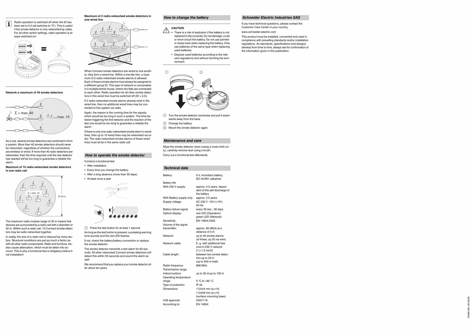
| Radio operation is switched off when the ID has been set to 0.0 (all switches to "0"). This is useful if the smoke detector is only networked by cable. For all other switch settings, radio operation is al-ways switched on!
Network a maximum of 40 smoke detectors
As a rule, several smoke detectors are combined to form a system. More than 40 smoke detectors should never be networked, regardless of whether the connections are wireless or wired. If more than 40 radio detectors are networked, then the time required until the last detector has reacted will be too long to guarantee a reliable fire alarm.Maximum of 10 radio-networked smoke detectors in one radio cell
The maximum radio module range of 30 m means that devices are surrounded by a radio cell with a diameter of 30 m. Within such a radio cell, 10 Connect smoke detec-tors may be radio-networked together.In reality, the size of a radio cell is reduced by many fac-tors. Structural conditions are just as much a factor as with all other radio components. Walls and furniture, etc. also cause attenuation, which must be taken into ac-count. This is why a functional test is obligatory before fi-nal installation!
=10
=0=01 2 3 4
10
1 2 3 4
1.3
1.21.4
1.1
= max. 401.x
1.x max. 10
23
5
4
1
10
7
8
9
6
∅ 30 mΣ = max. 10
Maximum of 2 radio-networked smoke detectors in one wired line
When Connect smoke detectors are wired to one anoth-er, they form a wired line. Within a line like this, a maxi-mum of 2 radio-networked smoke alarms is allowed. Each of these smoke alarms must always be assigned to a different group ID. This type of network is conceivable in a multiple family house, where two flats are connected to each other. Radio operation for all other smoke detec-tors in this wired line must be switched off (ID = 0.0).If 2 radio-networked smoke alarms already exist in the wired line, then no additional wired lines may be con-nected to this system via radio.Again, the reason is the running time for the signals, which would be too long in such a system. The time be-tween triggering the first detector and the reaction of the last one would be too long to guarantee a reliable fire alarm.If there is only one radio-networked smoke alarm in wired lines, then up to 10 wired lines may be networked via ra-dio. The radio-networked smoke alarms of these wired lines must all be in the same radio cell.
Conduct a functional test• After installation• Every time you change the battery• After a long absence (more than 30 days)• At least once a year
1 Press the test button for at least 1 second.As long as the test button is pressed, a pulsating warning tone sounds and the red LED flashes.If not, check the battery/battery connection or replace the smoke detector.The smoke detector transmits a test alarm for 60 sec-onds. All other networked Connect smoke detectors will detect this within 50 seconds and sound the alarm as well.We recommend that you replace your smoke detector af-ter about ten years.
How to operate the smoke detector
1.4
1.5
1.31.2
1.1
2.32.22.1 2.4
3.13.2
3.3
½ CAUTION• There is a risk of explosion if the battery is not
replaced in the correctly. Do not damage, crush or short circuit the battery. Do not use pointed or sharp tools when replacing the battery. Only use batteries of the same type when replacing used batteries.
• Dispose used batteries according to the rele-vant regulations and without harming the envi-ronment.
1 Turn the smoke detector clockwise and pull it down-wards away from the base.
2 Change the battery.3 Mount the smoke detector again.
Wipe the smoke detector clean (using a moist cloth on-ly), carefully remove dust using a brush.Carry out a functional test afterwards.
How to change the battery
Maintenance and care
Technical data
Battery: 9 V, monobloc battery, IEC 6LR61 (alkaline)
Battery lifeWith 230 V supply: approx. 4-5 years, depen-
dent of the self discharge of the battery
With Battery supply only: approx. 2,5 yearsSupply voltage: AC 230 V -15%/+10%
50 HzBattery failure signal: every 30 sec., 30 daysOptical display: red LED (Operation)
green LED (Network)Sensitivity: EN 14604:2005Volume of the signal transmitter: approx. 85 dB(A) at a
distance of 3 mNetwork: up to 40 smoke alarms
(of these, up 25 via wire)Network cable: E. g. with additional free
core in 230 V network (1 x 1,5 mm2)
Cable length: between two smoke detec-tors up to 25 m(up to 500 m total)
Radio frequency: 868 MHzTransmission rangeIndoor/outdoor up to 30 m/up to 100 mOperating temperature range: 0 °C to +60 °CType of protection IP 42Dimensions: 112x44 mm (ø x H)
112x59 mm (ø x H) (surface mounting base)
VdS approval: G207119Accordring to: EN 14604
1 2
If you have technical questions, please contact the Customer Care Center in your country. www.schneider-electric.comThis product must be installed, connected and used in compliance with prevailing standards and/or installation regulations. As standards, specifications and designs develop from time to time, always ask for confirmation of the information given in this publication.
Schneider Electric Industries SAS