Embed Size (px)
Citation preview

Edition 03/19 - Data subject to alteration - Regularly updated data on www.ari-armaturen.com! Data sheet 470003 englisch (english)
ARI-STEVI® 470 / 471 - ANSIPneumatic actuator ARI-DP 32 - 35• Reversible pneumatic actuator• Actuator with rolling diaphragm• Air supply pressure max. 6 bar• Stem protection by bellow• Maintenance-free O-ring sealing• Assembly of additional devices acc. to
DIN IEC 60534-6
Page 4
ARI-STEVI® 470 / 471 - ANSIElectric actuator ARI-PREMIO 2,2 - 25 kNARI-PREMIO-Plus 2G 2,2 - 25kN• Enclosure IP 65• 2 torque switches• Handwheel• Additional devices available, e.g. potentiometer
Page 12
ARI-STEVI® 470 / 471 - ANSIElectric actuator AUMA SAR 07.2 - 14.6• Enclosure IP 67• 2 torque switches• 2 travel switches • Handwheel • Overheating protection for motor as standard • Additional devices available, e.g. potentiometer• Explosion proof version available
Page 14
ARI-STEVI® 470 / 471 - ANSI (DN25-200)Control valve - straight through
with screwed seat ring, shaftguided plug and blow-out protected stem
With pneumatic and electric actuators
Fig. 470 - ANSI
Fig. 471 - ANSI
Fig. 470....4 - ANSI
2 Edition 03/19 - Data subject to alteration - Regularly updated data on www.ari-armaturen.com!
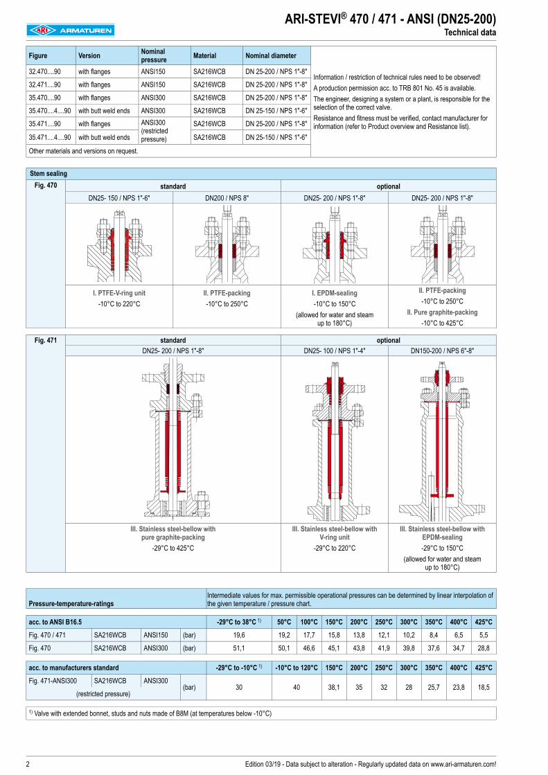
ARI-STEVI® 470 / 471 - ANSI (DN25-200)Technical data
Figure Version Nominal pressure Material Nominal diameter
Information / restriction of technical rules need to be observed!A production permission acc. to TRB 801 No. 45 is available. The engineer, designing a system or a plant, is responsible for the selection of the correct valve. Resistance and fitness must be verified, contact manufacturer for information (refer to Product overview and Resistance list).
32.470....90 with flanges ANSI150 SA216WCB DN 25-200 / NPS 1"-8"
32.471....90 with flanges ANSI150 SA216WCB DN 25-200 / NPS 1"-8"
35.470....90 with flanges ANSI300 SA216WCB DN 25-200 / NPS 1"-8"
35.470....4....90 with butt weld ends ANSI300 SA216WCB DN 25-150 / NPS 1"-6"
35.471....90 with flanges ANSI300 (restricted pressure)
SA216WCB DN 25-200 / NPS 1"-8"
35.471....4....90 with butt weld ends SA216WCB DN 25-150 / NPS 1"-6"
Other materials and versions on request.
Stem sealingFig. 470 standard optional
DN25- 150 / NPS 1"-6" DN200 / NPS 8" DN25- 200 / NPS 1"-8" DN25- 200 / NPS 1"-8"
I. PTFE-V-ring unit-10°C to 220°C
II. PTFE-packing -10°C to 250°C
I. EPDM-sealing-10°C to 150°C
(allowed for water and steam up to 180°C)
II. PTFE-packing -10°C to 250°C
II. Pure graphite-packing -10°C to 425°C
Fig. 471 standard optionalDN25- 200 / NPS 1"-8" DN25- 100 / NPS 1"-4" DN150-200 / NPS 6"-8"
III. Stainless steel-bellow with pure graphite-packing
-29°C to 425°C
III. Stainless steel-bellow with V-ring unit
-29°C to 220°C
III. Stainless steel-bellow with EPDM-sealing-29°C to 150°C
(allowed for water and steam up to 180°C)
Pressure-temperature-ratings Intermediate values for max. permissible operational pressures can be determined by linear interpolation of the given temperature / pressure chart.
acc. to ANSI B16.5 -29°C to 38°C 1) 50°C 100°C 150°C 200°C 250°C 300°C 350°C 400°C 425°C
Fig. 470 / 471 SA216WCB ANSI150 (bar) 19,6 19,2 17,7 15,8 13,8 12,1 10,2 8,4 6,5 5,5
Fig. 470 SA216WCB ANSI300 (bar) 51,1 50,1 46,6 45,1 43,8 41,9 39,8 37,6 34,7 28,8
acc. to manufacturers standard -29°C to -10°C 1) -10°C to 120°C 150°C 200°C 250°C 300°C 350°C 400°C 425°C
Fig. 471-ANSI300 SA216WCB ANSI300(bar) 30 40 38,1 35 32 28 25,7 23,8 18,5
(restricted pressure)
1) Valve with extended bonnet, studs and nuts made of B8M (at temperatures below -10°C)

3Edition 03/19 - Data subject to alteration - Regularly updated data on www.ari-armaturen.com!
ARI-STEVI® 470 / 471 - ANSI (DN25-200)Plug design
Plug design standard Guiding Rangeability
DN25-150Parabolic plug, metal seat
- Leakage class IV acc. to ANSI / FCI 70-2- from Kvs 0,1 - Flow characteristic:
equal percentage (glp) (from Kvs 100 modified) linear (lin) (from Kvs 1)
Plug shaft 50 : 1
DN200 V-port plug metal seat
- Leakage class IV acc. to ANSI / FCI 70-2 - Flow characteristic:
- equal percentage (glp) (from Kvs 100 modified) - linear (lin)
Plug shaft / Seat ring 30 : 1
Plug design optional Guiding Rangeability
Parabolic plug with PTFE-Soft seal (max. 200°C)
- Leakage class VI acc. to ANSI / FCI 70-2 - from Kvs 1,0 - Flow characteristic:
- equal percentage (glp) (from Kvs 100 modified) - linear (lin)
Plug shaft 50 : 1
Parabolic plug with armoured sealing edge
- Leakage class IV acc. to ANSI / FCI 70-2 - from Kvs 1,0 - Flow characteristic:
- equal percentage (glp) (from Kvs 100 modified) - linear (lin)
Plug shaft 50 : 1
Parabolic plug with Pressure balanced plug metal seat Piston seal: PTFE with stainless steel spring (max. 200°C)
- Leakage class IV acc. to ANSI / FCI 70-2 - from Kvs 6,3 - Flow characteristic:
- equal percentage (glp) (from Kvs 100 modified) - linear (lin)
Plug shaft 50 : 1
V-port plug metal seat
- Leakage class IV acc. to ANSI / FCI 70-2 - from Kvs 63 - Flow characteristic:
- equal percentage (glp) (from Kvs 100 modified) - linear (lin)
Plug shaft / Seat ring 30 : 1
Perforated plug metal seat
optional: Pressure balanced perforated plug metal seat Piston seal: PTFE with stainless steel spring (max. 200°C)
- Leakage class IV acc. to ANSI / FCI 70-2 - from Kvs 1 - Flow characteristic:
- equal percentage (glp) (from Kvs 100 modified) - linear (lin)
Flow direction for gas and steam to reduce the sound level
Flow direction for liquids at critical operating conditions (cavitation / flashing)
Plug shaft / Seat ring 30 : 1
Perforated plug with suppporting basket metal seat
- Leakage class IV acc. to ANSI / FCI 70-2 - Flow characteristic:
equal percentage (glp) (from Kvs 100 modified) linear (lin)
- multistage pressure reduction Flow direction for gas / steam and liquids to reduce the sound level at critical operating conditions
Plug shaft / Seat ring 30 : 1

4 Edition 03/19 - Data subject to alteration - Regularly updated data on www.ari-armaturen.com!
ARI-STEVI® 470 / 471 - ANSI (DN25-200)Pneumatic actuator ARI-DP
Heights and weightsDN 25 40 50 80 100 150 200NPS 1" 1 1/2" 2" 3" 4" 6" 8"
Fig. 470 DP32 H (mm) 473 504 504 522 524 584 --ANSI150 (kg) 18 25 27 43 61 111 --ANSI300 (kg) 20 28 30 50 75 136 --
DP33 H (mm) 528 559 559 588 590 650 --ANSI150 (kg) 24 31 33 49 67 117 --ANSI300 (kg) 26 34 36 56 81 142 --
DP34 H (mm) -- 694 694 723 725 785 844ANSI150 (kg) -- 61 63 79 97 147 248ANSI300 (kg) -- 64 66 86 111 172 264
DP34T H (mm) -- -- -- -- -- 1051 1094ANSI150 (kg) -- -- -- -- -- 223 319ANSI300 (kg) -- -- -- -- -- 248 335
DP34Tri H (mm) -- -- -- -- -- 1273 1316ANSI150 (kg) -- -- -- -- -- 257 353ANSI300 (kg) -- -- -- -- -- 282 369
DP35 H (mm) -- -- -- -- -- 1154 1197ANSI150 (kg) -- -- -- -- -- 422 518ANSI300 (kg) -- -- -- -- -- 447 534
Fig. 471 DP32 H (mm) 630 715 715 722 752 911 --ANSI150 (kg) 22 26 28 45 65 114 --ANSI300 (kg) 23 29 31 52 73 139 --
DP33 H (mm) 685 770 770 788 818 977 --ANSI150 (kg) 28 32 34 51 71 120 --ANSI300 (kg) 29 35 37 58 79 145 --
DP34 H (mm) -- 905 905 923 953 1112 1251ANSI150 (kg) -- 62 64 81 101 150 233ANSI300 (kg) -- 65 67 88 109 175 248
DP34T H (mm) -- -- -- -- -- 1573 1541ANSI150 (kg) -- -- -- -- -- 256 304ANSI300 (kg) -- -- -- -- -- 281 319
DP34Tri H (mm) -- -- -- -- -- 1795 1763ANSI150 (kg) -- -- -- -- -- 290 338ANSI300 (kg) -- -- -- -- -- 315 353
DP35 H (mm) -- -- -- -- -- 1643 --ANSI150 (kg) -- -- -- -- -- 455 --ANSI300 (kg) -- -- -- -- -- 480 --
Further dimensions refer to pages 18-23.
Control valve in straightway form with pneumatic actuator ARI-DP
Fig. 470 Fig. 471

5Edition 03/19 - Data subject to alteration - Regularly updated data on www.ari-armaturen.com!
DP32 / DP33 / DP34 DP34T DP34Tri DP35
Actuator data DP32 DP33 DP34 DP34T DP34Tri DP35
Ø A (mm) 250 300 405 755
Effective diaphragm area (cm2) 250 400 800 1600 2400 2800
Top mounted handwheel
Ø D1 (mm) 225 300 400 500
H1 (mm) 270 284 442 635 635 731
Weight (kg) 5 17 41 49
Further technical data of the actuator: refer to data sheet ARI-DP.
ARI-STEVI® 470 / 471 - ANSI (DN15-200)Pneumatic actuator ARI-DP

6 Edition 03/19 - Data subject to alteration - Regularly updated data on www.ari-armaturen.com!
max. permissible closing pressures on flow-to-open P2 = 0. Observe pressure-temperature-limits, refer to page 2.
DN 25 40 50 80 100 150NPS 1" 1 1/2" 2" 3" 4" 6"
Parabolic plugKvs-value (m3/h)
0,25 0,16 0,1
0,63 0,4
2,5 1,6 1
4 6,3 10 10 16 25 16 25 40 40 63 100 63 100 160 160
max. diff. pressure 1) (bar) 40 40 30 40 30 30 15 8 15 8 4 4
V-port plugKvs-value (m3/h) -- -- -- -- 63 100 63 100 160 160max. diff. pressure 1) (bar) -- -- -- -- 30 30 25 25
Perforated plugKvs-value (m3/h) -- 2,5 4 6,3 6,3 10 16 10 16 25 25 40 63 40 63 100 100max. diff. pressure 1) (bar) -- 40 40 40 40 40 40
Seat-Ø (mm) 3 5 12 18 22 25 25 32 40 32 40 50 50 65 80 65 80 100 100Travel (mm) 20 20 30 20 30 30 30 30
DP32 250 cm2
Spring closes on air failure
(stem extending by spring)
Sprin
g ran
ge (b
ar)
0,2-1,0
Air s
upply
pres
sure
min.
(bar
) 2)
1,2I. (bar) 30,6 29,2 21,2 8,1 4,8 3,3 2,5II. (bar) 20 18,6 11,9 3,8 1,8 1III. (bar)
0,4-1,2 1,4I. (bar) 51 51 51 25,8 16,8 12,6 11,9 6,7 3,8 6,7 3,8 2,1 2II. (bar) 51 51 49,9 21,4 13,8 10,3 8,8 4,8 2,6 4,8 2,6 1,3 1,1III. (bar) 9,7 9,4 8,4 7,5 7 6,5 6,5 3,6 1,8 3,6 1,8
0,8-2,4 2,7I. (bar) 51 40,8 31,4 30,6 18,3 11,3 18,3 11,3 6,9 6,8 3,7 2,2 3,7 2,2 1,2 1,2II. (bar) 51 51 37,8 29,1 27,5 16,4 10,1 16,4 10,1 6,1 5,9 3,2 1,9 3,2 1,9 1 1III. (bar) 27,5 27,2 26,2 25,3 24,7 24,3 24,3 15,2 9,3 15,2 9,3 5,6 5,6 3 1,8 3 1,8
1,5-2,9 3,2I. (bar) 51 51 51 38,6 38,6II. (bar) 51 51 51 36,7 36,7III. (bar) 40 40 40 40 40 40 40 35,5 35,5
2,0-3,8 4,1I. (bar) 51 51II. (bar) 51 51III. (bar) 40 40
DN 25 40 50 80 100 150NPS 1" 1 1/2" 2" 3" 4" 6"
Parabolic plugKvs-value (m3/h)
0,25 0,16 0,1
0,63 0,4
2,5 1,6 1
4 6,3 10 10 16 25 16 25 40 40 63 100 63 100 160 160
max. diff. pressure 1) (bar) 40 40 30 40 30 30 15 8 15 8 4 4
V-port plugKvs-value (m3/h) -- -- -- -- 63 100 63 100 160 160max. diff. pressure 1) (bar) -- -- -- -- 30 30 25 25
Perforated plugKvs-value (m3/h) 2,5 4 6,3 6,3 10 16 10 16 25 25 40 63 40 63 100 100max. diff. pressure 1) (bar) -- 40 40 40 40 40 40
Seat-Ø (mm) 3 5 12 18 22 25 25 32 40 32 40 50 50 65 80 65 80 100 100Travel (mm) 20 20 30 20 30 30 30 30
DP32 250 cm2
Spring opens on air failure
(stem retracting by spring)
Air s
upply
pres
sure
min.
(bar
) 2)
1,4I. (bar) 51 51 51 25,8 16,8 12,6 11,9 6,7 3,8 6,7 3,8 2,1 2II. (bar) 51 51 49,9 21,4 13,8 10,3 8,8 4,8 2,6 4,8 2,6 1,3 1,1III. (bar) 9,7 9,4 8,4 7,5 7 6,5 6,5 3,6 1,8 3,6 1,8
2I. (bar) 51 51 40,7 40 24,1 15,1 24,1 15,1 9,3 9,2 5,1 3,2 5,1 3,2 1,8 1,8II. (bar) 51 51 49,9 38,4 36,9 22,2 13,8 22,2 13,8 8,5 8,3 4,6 2,8 4,6 2,8 1,6 1,6III. (bar) 36,3 36,1 35 34,2 33,6 33,2 33,2 21 13,1 21 13,1 8 8 4,4 2,7 4,4 2,7 1,5 1,4
3I. (bar) 51 51 51 33,8 51 33,8 21,4 21,3 12,4 8 12,4 8 4,9 4,9II. (bar) 51 51 51 51 32,6 51 32,6 20,6 20,4 11,8 7,6 11,8 7,6 4,7 4,7III. (bar) 40 40 40 40 40 40 40 40 31,8 40 31,8 20,1 20,1 11,6 7,5 11,6 7,5 4,6 4,4
4I. (bar) 51 51 33,5 33,4 19,6 12,7 19,6 12,7 8 8II. (bar) 51 51 32,7 32,5 19 12,4 19 12,4 7,8 7,8III. (bar) 40 40 32,2 32,2 18,9 12,3 18,9 12,3 7,7 7,5
5I. (bar) 45,6 45,5 26,8 17,5 26,8 17,5 11 11II. (bar) 44,8 44,6 26,2 17,2 26,2 17,2 10,8 10,8III. (bar) 40 40 26,1 17 26,1 17 10,8 10,6
6I. (bar) 51 51 34 22,3 34 22,3 14,1 14,1II. (bar) 51 51 33,4 21,9 33,4 21,9 13,9 13,9III. (bar) 33,3 21,8 33,3 21,8 13,8 13,6
ARI-STEVI® 470 / 471 - ANSI (DN25-200)Closing pressures: Pneumatic actuator ARI-DP32
I. Fig. 470: PTFE-V-ring unit / EPDM-sealing II. Fig. 470: PTFE- / pure graphite-packing III. Fig. 471: Bellows seal1) max. differential pressure drop2) Air supply pressure max. to actuator: 6 bar Restriction: a) 5 bar b) 4,5 bar c) 4 bar d) 3,5 bar e) 3 bar

7Edition 03/19 - Data subject to alteration - Regularly updated data on www.ari-armaturen.com!
ARI-STEVI® 470 / 471 - ANSI (DN25-150)Closing pressures: Pneumatic actuator ARI-DP33
max. permissible closing pressures on flow-to-open P2 = 0. Observe pressure-temperature-limits, refer to page 2.
DN 25 40 50 80 100 150NPS 1" 1 1/2" 2" 3" 4" 6"
Parabolic plugKvs-value (m3/h)
0,25 0,16 0,1
0,63 0,4
2,5 1,6 1
4 6,3 10 10 16 25 16 25 40 40 63 100 63 100 160 160
max. diff. pressure 1) (bar) 40 40 30 40 30 30 15 8 15 8 4 4
V-port plugKvs-value (m3/h) -- -- -- -- 63 100 63 100 160 160max. diff. pressure 1) (bar) -- -- -- -- 30 30 25 25
Perforated plugKvs-value (m3/h) -- 2,5 4 6,3 6,3 10 16 10 16 25 25 40 63 40 63 100 100max. diff. pressure 1) (bar) -- 40 40 40 40 40 40
Seat-Ø (mm) 3 5 12 18 22 25 25 32 40 32 40 50 50 65 80 65 80 100 100Travel (mm) 20 20 30 20 30 30 30 30
DP33400 cm2
Spring closes on air failure
(stem extending by spring)
Sprin
g ran
ge (b
ar)
0,2-1,0
Air s
upply
pres
sure
min.
(bar
) 2)
1,2I. (bar) 51c) 51c) 43,7c) 18,6c) 11,9c) 8,8c) 8a) 4,3a) 2,3a) 4,3a) 2,3a) 1,1a) 1II. (bar) 45,6c) 44,2c) 34,4c) 14,2c) 8,9c) 6,5c) 5a) 2,4a) 1,1a) 2,4a) 1,1a)III. (bar) 6,1a) 5,8a) 4,8a) 3,9a) 3,3a) 2,9a) 2,9a) 1,2a) 1,2a)
0,4-1,2 1,4I. (bar) 51c) 46,6c) 31c) 23,7c) 22,9a) 13,5a) 8,3a) 13,5a) 8,3a) 4,9a) 4,8 2,5 1,4 2,5 1,4II. (bar) 51c) 51c) 51c) 42,3c) 28c) 21,4c) 19,9a) 11,6a) 7a) 11,6a) 7a) 4,1a) 3,9 2 1,1 2 1,1III. (bar) 20,2a) 19,9a) 18,9a) 18a) 17,5a) 17a) 17a) 10,5a) 6,3a) 10,5a) 6,3a) 3,7a) 3,7 1,8 1 1,8 1
0,8-2,4 2,7I. (bar) 51a) 51a) 51a) 51 32 20,2 32 20,2 12,6 12,5 7,1 4,5 7,1 4,5 2,7 2,7II. (bar) 51a) 51a) 51a) 49,7 30,1 19 30,1 19 11,8 11,6 6,6 4,1 6,6 4,1 2,5 2,5III. (bar) 40 40 40 40 40 40 40 28,9 18,2 28,9 18,2 11,3 11,3 6,4 4 6,4 4 2,4 2,2
1,5-3,0 3,3I. (bar) 41,1 41,1 26,1 26 15,1 9,8 15,1 9,8 6,1 6,1II. (bar) 39,9 39,9 25,3 25,1 14,6 9,5 14,6 9,5 5,9 5,9III. (bar) 39,1 39,1 24,8 24,8 14,4 9,3 14,4 9,3 5,8 5,6
1,7-2,7 3,1I. (bar) 51 51II. (bar) 51 51 51III. (bar) 40 40
2,0-4,0 4,5I. (bar) 51 51 35,7 35,6 20,9 13,6 20,9 13,6 8,5 8,5II. (bar) 51 51 34,9 34,7 20,4 13,3 20,4 13,3 8,3 8,3III. (bar) 40 40 34,4 34,4 20,2 13,1 20,2 13,1 8,2 8,1
DN 25 40 50 80 100 150NPS 1" 1 1/2" 2" 3" 4" 6"
Parabolic plugKvs-value (m3/h)
0,25 0,16 0,1
0,63 0,4
2,5 1,6 1
4 6,3 10 10 16 25 16 25 40 40 63 100 63 100 160 160
max. diff. pressure 1) (bar) 40 40 30 40 30 30 15 8 15 8 4 4
V-port plugKvs-value (m3/h) -- -- -- -- 63 100 63 100 160 160max. diff. pressure 1) (bar) -- -- -- -- 30 30 25 25
Perforated plugKvs-value (m3/h) 2,5 4 6,3 6,3 10 16 10 16 25 25 40 63 40 63 100 100max. diff. pressure 1) (bar) -- 40 40 40 40 40 40
Seat-Ø (mm) 3 5 12 18 22 25 25 32 40 32 40 50 50 65 80 65 80 100 100Travel (mm) 20 20 30 20 30 30 30 30
DP33400 cm2
Spring opens on air failure
(stem retracting by spring)
Air s
upply
pres
sure
min.
(bar
) 2)
1,4I. (bar) 51d) 51d) 51d) 46,6d) 31d) 23,7d) 22,9d) 13,5d) 8,3d) 13,5d) 8,3d) 4,9d) 4,8d) 2,5d) 1,4d) 2,5d) 1,4d)II. (bar) 51d) 51d) 51d) 42,3d) 28d) 21,4d) 19,9d) 11,6d) 7d) 11,6d) 7d) 4,1d) 3,9d) 2d) 1,1d) 2d) 1,1d)III. (bar) 20,2d) 19,9d) 18,9d) 18d) 17,5d) 17d) 17d) 10,5d) 6,3d) 10,5d) 6,3d) 3,7d) 3,7d) 1,8d) 1d) 1,8d) 1d)
2I. (bar) 51d) 51d) 51d) 51d) 41,2d) 26,2d) 41,2d) 26,2d) 16,5d) 16,4d) 9,4d) 6d) 9,4d) 6d) 3,7d) 3,7d)II. (bar) 51d) 51d) 51d) 51d) 39,3d) 24,9d) 39,3d) 24,9d) 15,7d) 15,5d) 8,9d) 5,7d) 8,9d) 5,7d) 3,4d) 3,4d)III. (bar) 40d) 40d) 40d) 40d) 40d) 40d) 40d) 38,2d) 24,2d) 38,2d) 24,2d) 15,2d) 15,2d) 8,7d) 5,5d) 8,7d) 5,5d) 3,4d) 3,2d)
3I. (bar) 51d) 51d) 51d) 51d) 35,7d) 35,6d) 20,9d) 13,6d) 20,9d) 13,6d) 8,5d) 8,5d)II. (bar) 51d) 51d) 51d) 51d) 34,9d) 34,7d) 20,4d) 13,3d) 20,4d) 13,3d) 8,3d) 8,3d)III. (bar) 40d) 40d) 40d) 40d) 34,4d) 34,4d) 20,2d) 13,1d) 20,2d) 13,1d) 8,2d) 8,1d)
4I. (bar) 51a) 51 32,4 21,2 32,4 21,2 13,4 13,4II. (bar) 51a) 51 31,8 20,9 31,8 20,9 13,2 13,2III. (bar) 40a) 40 31,6 20,7 31,6 20,7 13,1 12,9
5I. (bar) 43,8 28,8 43,8 28,8 18,3 18,3II. (bar) 43,3 28,5 43,3 28,5 18,1 18,1III. (bar) 40 28,4 40 28,4 18 17,8
6I. (bar) 51 36,4 51 36,4 23,2 23,2II. (bar) 51 36,1 51 36,1 23 23III. (bar) 36 36 22,9 22,7
I. Fig. 470: PTFE-V-ring unit / EPDM-sealing II. Fig. 470: PTFE- / pure graphite-packing III. Fig. 471: Bellows seal1) max. differential pressure drop2) Air supply pressure max. to actuator: 6 bar Restriction: a) 5 bar b) 4,5 bar c) 4 bar d) 3,5 bar e) 3 bar
8 Edition 03/19 - Data subject to alteration - Regularly updated data on www.ari-armaturen.com!
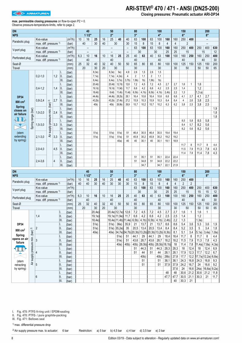
ARI-STEVI® 470 / 471 - ANSI (DN25-200)Closing pressures: Pneumatic actuator ARI-DP34
max. permissible closing pressures on flow-to-open P2 = 0. Observe pressure-temperature-limits, refer to page 2.
DN 40 50 80 100 150 200NPS 1 1/2" 2" 3" 4" 6" 8"
Parabolic plug Kvs-value (m3/h) 10 16 25 16 25 40 40 63 100 63 100 160 160 250 400 --max. diff. pressure 1) (bar) 40 30 40 30 30 15 8 15 8 4 4 2 --
V-port plug Kvs-value (m3/h) -- -- -- 63 100 63 100 160 160 250 400 250 400 630max. diff. pressure 1) (bar) -- -- -- 30 30 25 25 15 15 12
Perforated plug Kvs-value (m3/h) 6,3 10 16 10 16 25 25 40 63 40 63 100 100 160 250 160 250 400max. diff. pressure 1) (bar) 40 40 40 40 40 40 30
Seat-Ø (mm) 25 32 40 32 40 50 50 65 80 65 80 100 100 125 150 125 150 200Travel (mm) 20 30 20 30 30 30 30 50 50 50 65
DP34 800 cm2
Spring closes on air failure
(stem extending by spring)
Sprin
g ran
ge (b
ar)
0,2-1,0
Air s
upply
pres
sure
min.
(bar
) 2)
1,2I. (bar) 8,3e) 8,3e) 5e) 4,9 2,6 1,5 2,6 1,5II. (bar) 7,1e) 7,1e) 4,2e) 4 2 1,1 2 1,1III. (bar) 6,4e) 6,4e) 3,7e) 3,7b) 1,9b) 1b) 1,9b) 1b)
0,4-1,2 1,4I. (bar) 20,4d) 20,4d) 12,7d) 12,6 7,2 4,5 7,2 4,5 2,7 2,7 1,6 1 1,6II. (bar) 19,1d) 19,1d) 11,9d) 11,7 6,6 4,2 6,6 4,2 2,5 2,5 1,4 1,2III. (bar) 18,4d) 8,4d) 11,4b) 11,4d) 6,5b) 4,1b) 6,5b) 4,1b) 2,4b) 2,2 1,3 1,3 a)
0,8-2,4 2,7I. (bar) 44,4b) 44,4b) 28,2b) 28,1 16,4 10,6 16,4 10,6 6,6 6,6 4,1 2,7 4,1 2,7II. (bar) 43,2b) 43,2b) 27,4b) 27,2 15,9 10,3 15,9 10,3 6,4 6,4 4 2,6 3,8 2,5III. (bar) 40b) 40b) 26,9b) 26,9 15,7 10,2 15,7 10,2 6,3 6,2 3,8 2,5 3,8 2,5
1,0-2,0 2,4I. (bar) 1,9II. (bar) 1,8III. (bar) 1,8
1,5-3,0 3,3I. (bar) 8,5 5,8 8,5 5,8II. (bar) 8,4 5,7 8,2 5,6III. (bar) 8,2 5,6 8,2 5,6
2,1-3,0 3,3I. (bar) 51a) 51a) 51a) 51 46,4 30,5 46,4 30,5 19,4 19,4II. (bar) 51a) 51a) 51a) 51 45,9 30,2 45,9 30,2 19,2 19,2III. (bar) 40a) 40 40 30,1 40 30,1 19,1 18,9
2,0-4,0 4,5I. (bar) 11,7 8 11,7 8 4,4II. (bar) 11,5 7,9 11,3 7,8 4,3III. (bar) 11,4 7,8 11,4 7,8 4,3
2,4-3,6 4I. (bar) 51 35,1 51 35,1 22,4 22,4II. (bar) 51 34,8 51 34,8 22,2 22,2III. (bar) 34,7 34,7 22,1 21,9
DN 40 50 80 100 150 200NPS 1 1/2" 2" 3" 4" 6" 8"
Parabolic plug Kvs-value (m3/h) 10 16 25 16 25 40 40 63 100 63 100 160 160 250 400max. diff. pressure 1) (bar) 40 40 30 40 30 30 30 15 8 15 8 4 4 2 2
V-port plug Kvs-value (m3/h) 63 100 63 100 160 160 250 400 250 400 630max. diff. pressure 1) (bar) 30 30 25 25 15 15 15 12
Perforated plug Kvs-value (m3/h) 6,3 10 16 10 16 25 25 40 63 40 63 100 100 160 250 160 250 400max. diff. pressure 1) (bar) 40 40 40 40 40 40 30
Seat-Ø (mm) 25 32 40 32 40 50 50 65 80 65 80 100 100 125 150 125 150 200Travel (mm) 20 30 20 30 30 30 30 50 50 50 65
DP34
800 cm2
Spring opens on air
failure
(stem retracting by spring)
Air s
upply
pres
sure
min.
(bar
) 2)
1,4I. (bar) 20,4e) 20,4e)12,7e) 12,6 7,2 4,5 7,2 4,5 2,7 2,7 1,6 1 1,6 1II. (bar) 19,1e) 19,1e) 11,9e) 11,7 6,6 4,2 6,6 4,2 2,5 2,5 1,4 1,2III. (bar) 18,4e) 18,4e) 11,4b) 11,4e) 6,5b) 4,1b) 6,5b) 4,1b) 2,4b) 2,2 1,3 1,3a)
2I. (bar) 51e) 51e) 36e) 35,9 21 13,7 21 13,7 8,6 8,6 5,4 3,6 5,3 3,6 1,9II. (bar) 51e) 51e) 35,2e) 35 20,5 13,4 20,5 13,4 8,4 8,4 5,2 3,5 5 3,4 1,8III. (bar) 40e) 40e) 34,7e) 34,7b)20,3b)13,2b) 20,3b)13,2b) 8,3b) 8,1 5,1 3,4 5,1a) 3,4a) 1,8a)
3I. (bar) 51e) 51 44,1 29 44,1 29 18,4 18,4 11,7 8 11,7 8 4,4II. (bar) 51e) 51 43,6 28,7 43,6 28,7 18,2 18,2 11,5 7,9 11,3 7,8 4,3III. (bar) 40e) 40b) 40b) 28,5b) 40b) 28,5b)18,1b) 18 11,4 7,8 11,4a) 7,8a) 4,3a)
4I. (bar) 51 44,3 51 44,3 28,3 28,3 18 12,4 18 12,4 6,9II. (bar) 51 44 51 44 28,1 28,1 17,9 12,3 17,7 12,2 6,7III. (bar) 40b) 40b) 28b) 27,8 17,7 12,2 17,7a)12,2a) 6,8a)
5I. (bar) 51 51 38,1 38,1 24,3 16,8 24,3 16,8 9,3II. (bar) 51 51 37,9 37,9 24,2 16,7 24 16,6 9,2III. (bar) 37,6 24 16,6 24a) 16,6a) 9,2a)
6I. (bar) 48 48 30,6 21,2 30,6 21,2 11,8II. (bar) 47,7 47,7 30,5 21,1 30,3 21 11,7III. (bar) 40 30,3 21
I. Fig. 470: PTFE-V-ring unit / EPDM-sealing II. Fig. 470: PTFE- / pure graphite-packing III. Fig. 471: Bellows seal1) max. differential pressure drop2) Air supply pressure max. to actuator: 6 bar Restriction: a) 5 bar b) 4,5 bar c) 4 bar d) 3,5 bar e) 3 bar

9Edition 03/19 - Data subject to alteration - Regularly updated data on www.ari-armaturen.com!
ARI-STEVI® 470 / 471 - ANSI (DN25-200)Closing pressures: Pneumatic actuator ARI-DP34T
max. permissible closing pressures on flow-to-open P2 = 0. Observe pressure-temperature-limits, refer to page 2.
DN 150 200NPS 6" 8"
Parabolic plugKvs-value (m3/h) 160 250 400 --max. diff. pressure 1) (bar) 4 2 --
V-port plugKvs-value (m3/h) 160 250 400 250 400 630max. diff. pressure 1) (bar) 25 15 15 12
Perforated plugKvs-value (m3/h) 100 160 250 160 250 400max. diff. pressure 1) (bar) 40 40 30
Seat-Ø (mm) 100 125 150 125 150 200Travel (mm) 30 50 50 65
DP34T 1600 cm2
Spring closes on air failure
(stem extending by spring)
Sprin
g ran
ge (b
ar)
0,2-1,0
Air s
upply
pres
sure
min.
(bar
) 2)
1,5I. (bar) 2,7 1,6 1 1,6II. (bar) 2,2 1,2 1,2III. (bar) 2 a) 1,1 a) 1,3 e)
0,4-1,2 1,7I. (bar) 6,6 4,1 2,7 4,1 2,7 1,4II. (bar) 6,1 3,8 2,5 3,8 2,5 1,3III. (bar) 6 a) 3,7 a) 2,4 a) 3,8 d) 2,5 d) 1,3 d)
0,8-2,4 2,9I. (bar) 14,5 9,1 6,2 9,1 6,2II. (bar) 14 8,8 6 8,8 6III. (bar) 13,8 8,7 6 8,8 b) 6 b)
1,0-2,0 2,5I. (bar) 4,4II. (bar) 4,3III. (bar) 4,3 c)
1,5-3,0 3,5I. (bar) 18 12,4 18 12,4II. (bar) 17,7 12,2 17,7 12,2III. (bar) 17,6 12,1 17,7 a) 12,2 a)
2,1-3,0 3,5I. (bar) 40,1II. (bar) 39,6III. (bar) 39,4
2,0-4,0 4,5I. (bar) 24,3 16,8 24,3 16,8 9,3II. (bar) 24 16,6 24 16,6 9,2III. (bar) 23,9 16,5 24 16,6 9,2
2,4-3,6 4,1I. (bar) 46II. (bar) 45,5III. (bar) 40
DN 150 200NPS 6" 8"
Parabolic plugKvs-value (m3/h) 160 250 400 --max. diff. pressure 1) (bar) 4 2 --
V-port plugKvs-value (m3/h) 160 250 400 250 400 630max. diff. pressure 1) (bar) 25 15 15 12
Perforated plugKvs-value (m3/h) 100 160 250 160 250 400max. diff. pressure 1) (bar) 40 40 30
Seat-Ø (mm) 100 125 150 125 150 200Travel (mm) 30 50 50 65
DP34T 1600 cm2
Spring opens on air failure
(stem retracting by spring)
Air s
upply
pres
sure
min.
(bar
) 2)
1,5I. (bar) 8,6 5,3 3,6 5,3 3,6 1,9II. (bar) 8,1 5 3,4 5 3,4 1,8III. (bar) 7,9 a) 4,9 a) 3,3 a) 5,1 e) 3,4 e) 1,8 e)
2I. (bar) 18,4 11,7 8 11,7 8 4,4II. (bar) 17,9 11,3 7,8 11,3 7,8 4,3III. (bar) 17,8 a) 11,2 a) 7,7 a) 11,4 e) 7,8 e) 4,3 e)
3I. (bar) 38,1 24,3 16,8 24,3 16,8 9,3II. (bar) 37,6 24 16,6 24 16,6 9,2III. (bar) 37,4 a) 23,9 a) 16,5 a) 24 e) 16,6 e) 9,2 e)
4I. (bar) 51 36,9 25,6 36,9 25,6 14,3II. (bar) 51 36,6 25,4 36,6 25,4 14,2III. (bar) 40 a) 36,5 a) 25,3 a)
5I. (bar) 49,6 34,4 49,6 34,4 19,3II. (bar) 49,2 34,2 49,2 34,2 19,1III. (bar) 40 a) 34,1 a)
6I. (bar) 51 43,2 51 43,2 24,2II. (bar) 51 42,9 51 42,9 24,1III. (bar)
I. Fig. 470: EPDM-sealing II. Fig. 470: PTFE- / pure graphite-packing III. Fig. 471: Bellows seal1) max. differential pressure drop2) Air supply pressure max. to actuator: 6 bar Restriction: a) 5 bar b) 4,5 bar c) 4 bar d) 3,5 bar e) 3 bar f) 2,5 bar

10 Edition 03/19 - Data subject to alteration - Regularly updated data on www.ari-armaturen.com!
ARI-STEVI® 470 / 471 - ANSI (DN25-200)Closing pressures: Pneumatic actuator ARI-DP34Tri
max. permissible closing pressures on flow-to-open P2 = 0. Observe pressure-temperature-limits, refer to page 2.
DN 150 200NPS 6" 8"
Parabolic plugKvs-value (m3/h) 160 250 400 --max. diff. pressure 1) (bar) 4 2 --
V-port plugKvs-value (m3/h) 160 250 400 250 400 630max. diff. pressure 1) (bar) 25 15 15 12
Perforated plugKvs-value (m3/h) 100 160 250 160 250 400max. diff. pressure 1) (bar) 40 40 30
Seat-Ø (mm) 100 125 150 125 150 200Travel (mm) 30 50 50 65
DP34Tri 2400 cm2
Spring closes on air failure
(stem extending by spring)
Sprin
g ran
ge (b
ar)
0,2-1,0
Air s
upply
pres
sure
min.
(bar
) 2)
1,5I. (bar) 4,6 a) 2,8 a) 1,9 a) 2,8 a) 1,9 a)II. (bar) 4,1 a) 2,5 a) 1,6 a) 2,5 a) 1,6 a)III. (bar) 4 d) 2,4 d) 1,6 d) 2,5 f) 1,6 f)
0,4-1,2 1,7I. (bar) 10,6 a) 6,6 a) 4,5 a) 6,6 a) 4,5 a) 2,4 a)II. (bar) 10,1 a) 6,3 a) 4,3 a) 6,3 a) 4,3 a) 2,3 a)III. (bar) 9,9 c) 6,2 c) 4,2 c) 6,3 f) 4,3 f) 2,3 f)
0,8-2,4 2,9I. (bar) 22,4 a) 14,2 a) 9,8 a) 14,2 a) 9,8 a) 5,4 a)II. (bar) 21,9 a) 13,9 a) 9,5 a) 13,9 a) 9,5 a) 5,3 a)III. (bar) 21,7 a) 13,8 a) 9,5 a) 13,9 d) 9,6 d) 5,3 d)
1,0-2,0 2,5I. (bar) 6,9 a)II. (bar) 6,7 a)III. (bar) 6,8 d)
1,5-3,0 3,5I. (bar) 27,5 a) 19 a) 27,5 a) 19 a) 10,6 a)II. (bar) 27,1 a) 18,8 a) 27,1 a) 18,8 a) 10,5 a)III. (bar) 27 a) 18,7 a) 27,2 b) 18,8 b) 10,5 b)
2,1-3,0 3,5I. (bar) 51 a)II. (bar) 51 a)III. (bar) 40 a)
2,0-4,0 4,5I. (bar) 36,9 a) 25,6 a) 36,9 a) 25,6 a) 14,3 a)II. (bar) 36,6 a) 25,4 a) 36,6 a) 25,4 a) 14,2 a)III. (bar) 36,5 a) 25,3 a)
I. Fig. 470: EPDM-sealing II. Fig. 470: PTFE- / pure graphite-packing III. Fig. 471: Bellows seal1) max. differential pressure drop2) Air supply pressure max. to actuator: 5 bar Restriction: a) 5 bar b) 4,5 bar c) 4 bar d) 3,5 bar e) 3 bar

11Edition 03/19 - Data subject to alteration - Regularly updated data on www.ari-armaturen.com!
ARI-STEVI® 470 / 471 - ANSI (DN25-200)Closing pressures: Pneumatic actuator ARI-DP35
max. permissible closing pressures on flow-to-open P2 = 0. Observe pressure-temperature-limits, refer to page 2.
DN 150 200NPS 6" 8"
Parabolic plugKvs-value (m3/h) 250 400 --max. diff. pressure 1) (bar) 2 --
V-port plugKvs-value (m3/h) 250 400 250 400 630max. diff. pressure 1) (bar) 15 15 12
Perforated plugKvs-value (m3/h) 160 250 160 250 400max. diff. pressure 1) (bar) 40 40 30
Seat-Ø (mm) 125 150 125 150 200Travel (mm) 50 50 65
DP35 2800 cm2
Spring closes on air failure
(stem extending by spring)
Sprin
g ran
ge (b
ar) 2,45-3,28
Air s
upply
pres
sure
min.
(bar
) 2)
3,8
I./II. (bar) 51 37,4 51 37,4
III. (bar) 40 a) 37,3 a)
2,97-3,8 4,3 I./II. (bar) 45,5 45,5
2,72-3,8 4,3 I./II. (bar) 23,4
DN 150 200
NPS 6" 8"
Parabolic plugKvs-value (m3/h) 250 400 --
max. diff. pressure 1) (bar) 2 --
V-port plugKvs-value (m3/h) 250 400 250 400 630
max. diff. pressure 1) (bar) 15 15 12
Perforated plugKvs-value (m3/h) 160 250 160 250 400
max. diff. pressure 1) (bar) 40 40 30
Seat-Ø (mm) 125 150 125 150 200
Travel (mm) 50 50 65
DP35 2800 cm2
Spring opens on air failure
(stem retracting by spring) Ai
r sup
ply pr
essu
re m
in. (b
ar) 2)
1,5I./II. (bar) 12,7 b) 8,7 b) 12,7 b) 8,7 b) 4,1 b)
III. (bar) 12,6 e) 8,6 e)
2I./II. (bar) 23,9 b) 16,6 b) 23,9 b) 16,6 b) 8,5 b)
III. (bar) 23,8 e) 16,5 e)
3I./II. (bar) 46,5 b) 32,2 b) 46,5 b) 32,2 b) 17,3 b)
III. (bar) 40 e) 32,2 e)
4 I./II. (bar) 51 b) 47,9 ) 51 b) 47,9 b) 26,2 b)
4,5 I./II. (bar) 51 b) 51 b) 30,6 b)
I. Fig. 470: EPDM-sealing II. Fig. 470: PTFE- / pure graphite-packing III. Fig. 471: Bellows seal1) max. differential pressure drop2) Air supply pressure max. to actuator: 6 bar Restriction: a) 5 bar b) 4,5 bar c) 4 bar d) 3,5 bar e) 3 bar

12 Edition 03/19 - Data subject to alteration - Regularly updated data on www.ari-armaturen.com!
ARI-STEVI® 470 / 471 - ANSI (DN25-200)Electric actuator ARI-PREMIO / PREMIO-Plus 2G
Heights and weightsDN 25 40 50 80 100 150 200NPS 1" 1 1/2" 2" 3" 4" 6" 8"
Fig. 470 2,2 kN H (mm) 582 613 613 642 644 724 --ANSI150 (kg) 15 21 23 39 58 108 --ANSI300 (kg) 16 24 26 46 72 133 --
5 kN H (mm) 582 613 613 642 644 724 842ANSI150 (kg) 16 22 24 40 59 109 183ANSI300 (kg) 17 25 27 47 73 134 200
12 kN 15 kN
H (mm) -- 787 787 816 818 878 996ANSI150 (kg) -- 26 28 44 63 113 186ANSI300 (kg) -- 29 31 51 77 138 203
25 kN H (mm) -- -- -- 816 818 878 952ANSI150 (kg) -- -- -- 45 64 114 187ANSI300 (kg) -- -- -- 52 78 139 204
Fig. 471 2,2 kN H (mm) 739 824 824 842 872 1045 --ANSI150 (kg) 18 23 25 41 62 111 --ANSI300 (kg) 19 26 28 48 70 136 --
5 kN H (mm) 739 824 824 842 872 1045 1264ANSI150 (kg) 19 24 26 42 63 112 209ANSI300 (kg) 20 27 29 49 71 137 226
12 kN 15 kN
H (mm) -- 998 998 1016 1046 1205 1433ANSI150 (kg) -- 28 30 46 67 116 212ANSI300 (kg) -- 31 33 53 75 141 229
25 kN H (mm) -- -- -- 1016 1046 1205 1433ANSI150 (kg) -- -- -- 47 68 117 213ANSI300 (kg) -- -- -- 54 76 142 230
Further dimensions refer to pages 18-23.
Control valve in straightway form with electric actuator ARI-PREMIO / PREMIO-Plus 2G
Fig. 470....90 Fig. 471....90
Actuator data 2,2 - 5 kN 12 - 25 kNA (mm) 171 210B (mm) 156 184C (mm) 50 90Ø D1 (mm) 90 130X (mm) 150 200Further technical data of the actuator: refer to data sheet ARI-PREMIO/PREMIO-Plus 2G

13Edition 03/19 - Data subject to alteration - Regularly updated data on www.ari-armaturen.com!
max. permissible closing pressures on flow-to-open P2 = 0. Observe pressure-temperature-limits, refer to page 2.
DN 25 40 50 80 100 150 200
NPS 1" 1 1/2" 2" 3" 4" 6" 8"
Parabolic plugKvs-value (m3/h)
0,25 0,16 0,1
0,63 0,4
2,5 1,6 1
4 6,3 10 10 16 25 16 25 40 40 63 100 63 100 160 160 250 400 --
max. diff. pressure 1) (bar) 40 40 30 40 30 30 15 8 15 8 4 4 2 --
V-port plugKvs-value (m3/h) -- -- -- 63 100 63 100 160 160 250 400 250 400 630
max. diff. pressure 1) (bar) -- -- -- 30 30 25 25 15 15 12
Perforated plugKvs-value (m3/h) --
2,5 1,6 1
4 6,3 6,3 10 16 10 16 25 25 40 63 40 63 100 100 160 250 160 250 400
max. diff. pressure 1) (bar) -- 40 40 40 40 40 40 40 30
Seat-Ø (mm) 3 5 12 18 22 25 25 32 40 32 40 50 50 65 80 65 80 100 100 125 150 125 150 200
Travel (mm) 20 20 30 20 30 30 30 30 50 50 50 65
2,2 kN
Closing pressure
I. (bar) 51 51 51 51 46,7 35,9 35,2 21,1 13,2 21,1 13,2 8,1 8 4,4 2,7 4,4 2,7 1,5 1,5
II. (bar) 51 51 51 51 43,7 33,7 32,1 19,2 11,9 19,2 11,9 7,3 7,1 3,9 2,3 3,9 2,3 1,3 1,3
III. (bar) 31,8 31,5 30,5 29,6 29,1 28,6 28,6 18 11,2 18 11,2 6,8 6,8 3,7 2,2 3,7 2,2 1,2 1
Operating time (50 Hz) (s) 53 53 79 53 79 79 79 79
Operating speed (mm/s) 0,38
5 kN
Closing pressure
I. (bar) 51 51 51 51 34,6 51 34,6 21,9 21,8 12,6 8,2 12,6 8,2 5 5 3,1 2 3,1 2 1
II. (bar) 51 51 51 51 33,4 51 33,4 21,1 20,9 12,1 7,8 12,1 7,8 4,8 4,8 2,9 1,9 2,7 1,8
III. (bar) 40 40 40 40 40 40 40 40 32,6 40 32,6 20,6 20,6 11,9 7,7 11,9 7,7 4,7 4,5 2,8 1,8 2,8 1,8
Operating time (s) 53 53 79 53 79 79 79 79 132 132
Operating speed (mm/s) 0,38
12 kN
Closing pressure
I. (bar) 51 51 51 51 33,2 21,8 33,2 21,8 13,8 13,8 8,7 5,9 8,7 5,9 3,2
II. (bar) 51 51 51 51 32,7 21,5 32,7 21,5 13,6 13,6 8,6 5,8 8,4 5,7 3,1
III. (bar) 40 40 40 40 32,5 21,3 32,5 31,3 13,5 13,3 8,4 5,7 8,4 5,7 3,1
Operating time (s) 79 79 79 79 79 132 132 171
Operating speed (mm/s) 0,38 0,38
15 kN
Closing pressure
I. (bar) 42,1 27,7 42,1 27,7 17,6 17,6 11,1 7,6 11,1 7,6 4,2
II. (bar) 41,5 27,3 41,5 27,3 17,3 17,3 11 7,5 10,8 7,4 4
III. (bar) 40 27,2 40 27,2 17,3 17,1 10,8 7,4 10,8 7,4 4,1
Operating time (s) 79 79 79 132 132 171
Operating speed (mm/s) 0,38
25 kN
Closing pressure
I. (bar) 51 47,2 51 47,2 30,1 30,1 19,1 13,2 19,1 13,2 7,3
II. (bar) 51 46,8 51 46,8 29,9 30 19,1 13 18,8 13,2 7,2
III. (bar) 40 40 40 29,8 29,6 18,8 13 18,8 13 7,2
Operating time (s) 79 79 79 132 132 171
Operating speed (mm/s) 0,38
Further operating speeds: refer to data sheet ARI-PREMIO/PREMIO-Plus 2G
ARI-STEVI® 470 / 471 - ANSI (DN25-200)Closing pressures: Electric actuator ARI-PREMIO / PREMIO-Plus 2G
I. Fig. 470: PTFE-V-ring unit / EPDM-sealing II. Fig. 470: PTFE- / pure graphite-packing III. Fig. 471: Bellows seal
1) max. differential pressure drop 2) Based on a frequency of 50Hz the control speed and power consumption of the synchronous motors PREMIO 2,2kN are 20% higher at frequency of 60 Hz.
Operating time [s]=Travel [mm]Operating speed [mm/s]
14 Edition 03/19 - Data subject to alteration - Regularly updated data on www.ari-armaturen.com!
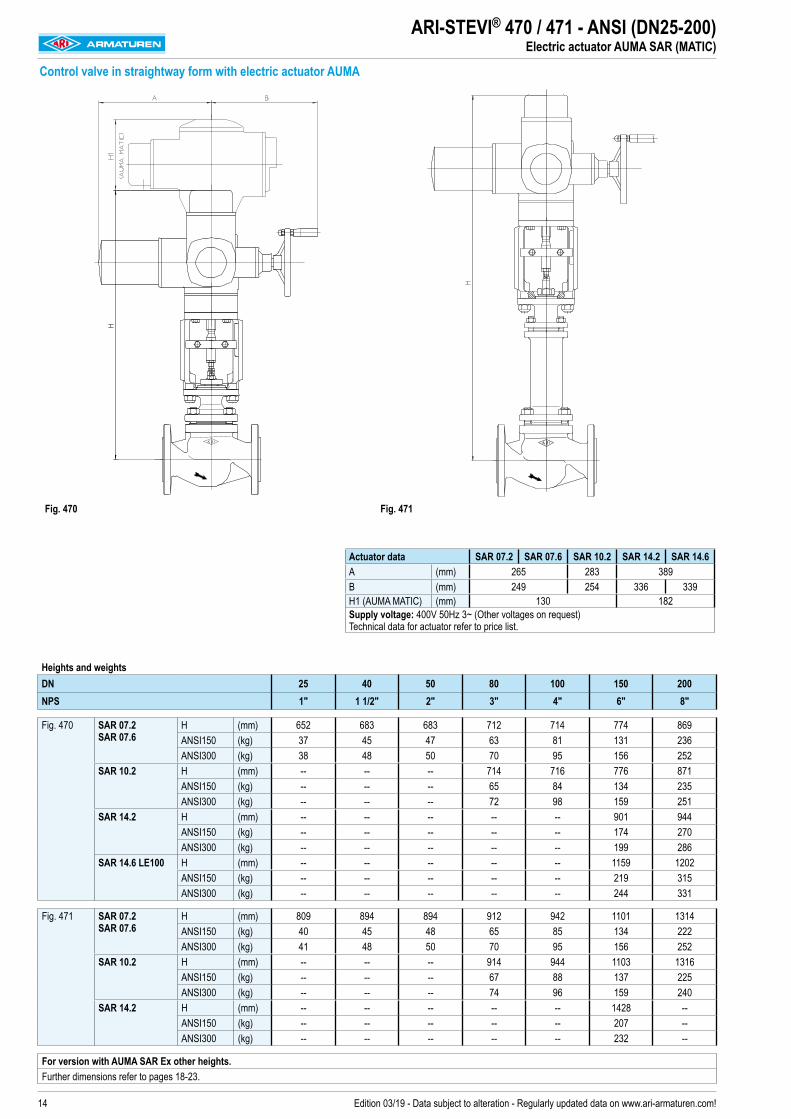
ARI-STEVI® 470 / 471 - ANSI (DN25-200)Electric actuator AUMA SAR (MATIC)
Heights and weights DN 25 40 50 80 100 150 200NPS 1" 1 1/2" 2" 3" 4" 6" 8"
Fig. 470 SAR 07.2 SAR 07.6
H (mm) 652 683 683 712 714 774 869ANSI150 (kg) 37 45 47 63 81 131 236ANSI300 (kg) 38 48 50 70 95 156 252
SAR 10.2 H (mm) -- -- -- 714 716 776 871ANSI150 (kg) -- -- -- 65 84 134 235ANSI300 (kg) -- -- -- 72 98 159 251
SAR 14.2 H (mm) -- -- -- -- -- 901 944ANSI150 (kg) -- -- -- -- -- 174 270ANSI300 (kg) -- -- -- -- -- 199 286
SAR 14.6 LE100 H (mm) -- -- -- -- -- 1159 1202ANSI150 (kg) -- -- -- -- -- 219 315ANSI300 (kg) -- -- -- -- -- 244 331
Fig. 471 SAR 07.2 SAR 07.6
H (mm) 809 894 894 912 942 1101 1314ANSI150 (kg) 40 45 48 65 85 134 222ANSI300 (kg) 41 48 50 70 95 156 252
SAR 10.2 H (mm) -- -- -- 914 944 1103 1316ANSI150 (kg) -- -- -- 67 88 137 225ANSI300 (kg) -- -- -- 74 96 159 240
SAR 14.2 H (mm) -- -- -- -- -- 1428 --ANSI150 (kg) -- -- -- -- -- 207 --ANSI300 (kg) -- -- -- -- -- 232 --
For version with AUMA SAR Ex other heights.Further dimensions refer to pages 18-23.
Control valve in straightway form with electric actuator AUMA
Fig. 470 Fig. 471
Actuator data SAR 07.2 SAR 07.6 SAR 10.2 SAR 14.2 SAR 14.6A (mm) 265 283 389B (mm) 249 254 336 339H1 (AUMA MATIC) (mm) 130 182Supply voltage: 400V 50Hz 3~ (Other voltages on request) Technical data for actuator refer to price list.

15Edition 03/19 - Data subject to alteration - Regularly updated data on www.ari-armaturen.com!
Fig. 470DN 25 40 50 80 100 150 200
NPS 1" 1 1/2" 2" 3" 4" 6" 8"
Parabolic plugKvs-value (m3/h) 10 10 16 25 16 25 40 40 63 100 63 100 160 160 250 400 --
max. diff. pressure 1) (bar) 40 40 30 40 30 30 15 8 15 8 4 4 2 --
V-port plugKvs-value (m3/h) -- -- -- 63 100 63 100 160 160 250 400 250 400 630
max. diff. pressure 1) (bar) -- -- -- 30 30 25 25 15 15 12
Perforated plugKvs-value (m3/h) 6,3 6,3 10 16 10 16 25 25 40 63 40 63 100 100 160 250 160 250 400
max. diff. pressure 1) (bar) 40 40 40 40 40 40 40 30
Seat-Ø (mm) 25 25 32 40 32 40 50 50 65 80 65 80 100 100 125 150 125 150 200
Travel (mm) 20 20 30 20 30 30 30 30 50 50 50 65
SAR 07.2 Output drive Form A TR 20 x 4 - LH
Closing pressure I./II.
shut off (bar) 51 51 51 51 51 46,4 30,6 46,4 30,6 19,4
controlling 2) (bar) 51 51 51 37,6 37,4 21,9 14,3 21,9 14,3 9
Torque (Nm) 15 15 15 20 20 30 30
Operating time (50 Hz) (s) 54 54 56 54 56 56 56
Output drive (rpm) 5,6 5,6 8 5,6 8 8 8
SAR 07.6 Output drive Form A TR 26 x 5 - LH
Closing pressure I./II.
shut off (bar) 51 51 43,1 51 43,1 27,5 27,5 17,5 12 17,3 11,9 6,6
controlling 2) (bar) 51 51 31,3 20,6 31,3 20,6 13 13 8,2 5,6 8 5,5 2,9
Torque (Nm) 30 30 50 60 50 60 60 60
Operating time (50 Hz) (s) 64 64 64 64 55 55 71
Output drive (rpm) 5,6 5,6 5,6 5,6 11 11
SAR 10.2 Output drive Form A TR 26 x 5 - LH
Closing pressure I./II.
shut off (bar) 51 51 51 51 41,9 41,9 26,8 18,5 35,8 24,8 13,9
controlling 2) (bar) 51 43,1 51 43,1 27,5 27,5 17,5 12 17,3 11,9 6,6
Torque (Nm) 60 80 60 80 90 90 120
Operating time (50 Hz) (s) 64 64 64 55 55 71
Output drive (rpm) 5,6 5,6 5,6 11 11
SAR 14.2 Output drive Form A TR 30 x 6 - LH
Closing pressure I./II.
shut off (bar) 51 51 42,7 51 42,7 24
controlling 2) (bar) 45,2 28,9 20 28,9 20 11,1
Torque (Nm) 150 225 250 225 250
Operating time (50 Hz) (s) 38 63 63 59
Output drive (rpm) 8 8 11
SAR 14.6 with LE100.1 Output drive Form A TR 40 x 7 - LH
Closing pressure I./II.
shut off (bar) 51 51 31,7
controlling 2) (bar) 51 40 27,7 40 27,7 15,5
Torque (Nm) 250 300 400 300 400 400
Operating time (50 Hz) (s) 46 54 54 51
Output drive (rpm) 5,6 8 8 11
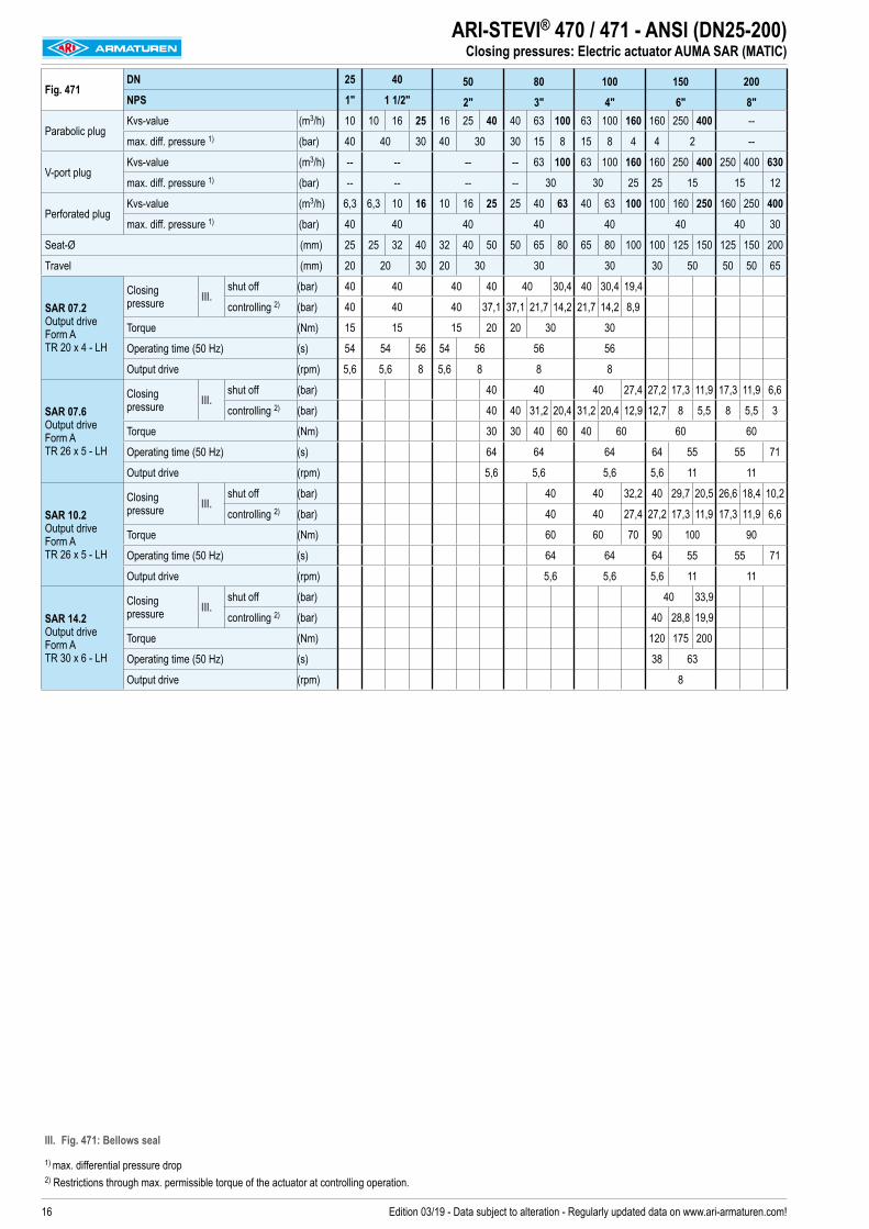
ARI-STEVI® 470 / 471 - ANSI (DN25-200)Closing pressures: Electric actuator AUMA SAR (MATIC)
I. Fig. 470: PTFE-V-ring unit / EPDM-sealing II. Fig. 470: PTFE- / pure graphite-packing
1) max. differential pressure drop 2) Restrictions through max. permissible torque of the actuator at controlling operation.
16 Edition 03/19 - Data subject to alteration - Regularly updated data on www.ari-armaturen.com!
Fig. 471DN 25 40 50 80 100 150 200NPS 1" 1 1/2" 2" 3" 4" 6" 8"
Parabolic plugKvs-value (m3/h) 10 10 16 25 16 25 40 40 63 100 63 100 160 160 250 400 --
max. diff. pressure 1) (bar) 40 40 30 40 30 30 15 8 15 8 4 4 2 --
V-port plugKvs-value (m3/h) -- -- -- -- 63 100 63 100 160 160 250 400 250 400 630
max. diff. pressure 1) (bar) -- -- -- -- 30 30 25 25 15 15 12
Perforated plugKvs-value (m3/h) 6,3 6,3 10 16 10 16 25 25 40 63 40 63 100 100 160 250 160 250 400
max. diff. pressure 1) (bar) 40 40 40 40 40 40 40 30
Seat-Ø (mm) 25 25 32 40 32 40 50 50 65 80 65 80 100 100 125 150 125 150 200
Travel (mm) 20 20 30 20 30 30 30 30 50 50 50 65
SAR 07.2 Output drive Form A TR 20 x 4 - LH
Closing pressure III.
shut off (bar) 40 40 40 40 40 30,4 40 30,4 19,4
controlling 2) (bar) 40 40 40 37,1 37,1 21,7 14,2 21,7 14,2 8,9
Torque (Nm) 15 15 15 20 20 30 30
Operating time (50 Hz) (s) 54 54 56 54 56 56 56
Output drive (rpm) 5,6 5,6 8 5,6 8 8 8
SAR 07.6 Output drive Form A TR 26 x 5 - LH
Closing pressure III.
shut off (bar) 40 40 40 27,4 27,2 17,3 11,9 17,3 11,9 6,6
controlling 2) (bar) 40 40 31,2 20,4 31,2 20,4 12,9 12,7 8 5,5 8 5,5 3
Torque (Nm) 30 30 40 60 40 60 60 60
Operating time (50 Hz) (s) 64 64 64 64 55 55 71
Output drive (rpm) 5,6 5,6 5,6 5,6 11 11
SAR 10.2 Output drive Form A TR 26 x 5 - LH
Closing pressure III.
shut off (bar) 40 40 32,2 40 29,7 20,5 26,6 18,4 10,2
controlling 2) (bar) 40 40 27,4 27,2 17,3 11,9 17,3 11,9 6,6
Torque (Nm) 60 60 70 90 100 90
Operating time (50 Hz) (s) 64 64 64 55 55 71
Output drive (rpm) 5,6 5,6 5,6 11 11
SAR 14.2 Output drive Form A TR 30 x 6 - LH
Closing pressure III.
shut off (bar) 40 33,9
controlling 2) (bar) 40 28,8 19,9
Torque (Nm) 120 175 200
Operating time (50 Hz) (s) 38 63
Output drive (rpm) 8
ARI-STEVI® 470 / 471 - ANSI (DN25-200)Closing pressures: Electric actuator AUMA SAR (MATIC)
III. Fig. 471: Bellows seal
1) max. differential pressure drop 2) Restrictions through max. permissible torque of the actuator at controlling operation.

17Edition 03/19 - Data subject to alteration - Regularly updated data on www.ari-armaturen.com!
ARI-STEVI® 470 / 471 - ANSI (DN25-200)Notes

18 Edition 03/19 - Data subject to alteration - Regularly updated data on www.ari-armaturen.com!
ARI-STEVI® 470 / 471 - ANSI (DN25-150)Dimensions: Standard design with flanges
Control valve in straightway form with flanges
Fig. 470....90DN25-150 / NPS 1"-6"
(e.g.: DP32-34; PREMIO 2,2-25kN; AUMA 07.2-10.2)
Fig. 471....90 DN25-150 / NPS 1"-6"
(e.g.: DP32-34; PREMIO 2,2-25kN; AUMA 07.2-10.2)
DN 25 40 50 80 100 150NPS 1" 1 1/2" 2" 3" 4" 6"
Dimensions
MFig. 470 (mm) M10 M12 M16 x 1,5Fig. 471 (mm) M12 M14 x 1,5 M16 x 1,5
H1Fig. 470 (mm) 134 165 165 194 196 256Fig. 471 (mm) 291 376 376 394 424 583
H2 Fig. 470 / Fig. 471 (mm) 83A Fig. 470 / Fig. 471 (mm) 100ØB Fig. 470 / Fig. 471 (mm) 2 x 16
Face-to-face dimension Form RF acc. to ANSI / ISA - S75.03-1992 (Face-to-face dimension for Form RTJ refer to page 26.)
LANSI150 (mm) 184 222 254 298 352 451ANSI300 (mm) 197 235 267 318 368 473
Flanges acc. to ANSI B16.5
ØDANSI150 (mm) 110 125 150 190 230 280ANSI300 (mm) 124 155 165 210 254 318
ØKANSI150 (mm) 79 98 121 152 191 241ANSI300 (mm) 89 114 127 168 200 270
n x ØdANSI150 (mm) 4 x 16 4 x 16 4 x 19 4 x 19 8 x 19 8 x 22ANSI300 (mm) 4 x 19 4 x 22 8 x 19 8 x 22 8 x 22 12 x 22
Weights
Fig. 470ANSI150 (kg) 9 16 18 34 52 102ANSI300 (kg) 11 19 21 41 66 127
Fig. 471ANSI150 (kg) 13 17 19 36 56 105ANSI300 (kg) 14 20 22 43 64 130
max. permissible thrustFig. 470 (kN) 12,7 18,2 40,6Fig. 471 (kN) 18,2 29,6 40,6

19Edition 03/19 - Data subject to alteration - Regularly updated data on www.ari-armaturen.com!
DN 200NPS 8"
Dimensions
MFig. 470 (mm) M20Fig. 471 (mm) M16 M20
H1Fig. 470 (mm) 315Fig. 471 (mm) 796 722
H2Fig. 470 (mm) 98Fig. 471 (mm) 83 98
H4 Fig. 470 (mm) 283H5 Fig. 470 (mm) 130A Fig. 470 / Fig. 471 (mm) 100ØB Fig. 470 (mm) 2 x 16A1 Fig. 470 / Fig. 471 (mm) 150ØB1 Fig. 470 / Fig. 471 (mm) 4 x 16A2 Fig. 470 (mm) 170M1 Fig. 470 (mm) M20T Fig. 470 (mm) 32
Face-to-face dimension Form RF acc. to ANSI / ISA - S75.03-1992 (Face-to-face dimension for Form RTJ refer to page 26.)
LANSI150 (mm) 543ANSI300 (mm) 568
Flanges acc. to ANSI B16.5
ØDANSI150 (mm) 345ANSI300 (mm) 381
ØKANSI150 (mm) 298ANSI300 (mm) 330
n x ØdANSI150 (mm) 8 x 22ANSI300 (mm) 12 x 25
Weights
Fig. 470ANSI150 (kg) 203ANSI300 (kg) 193
Fig. 471ANSI150 (kg) 202 201ANSI300 (kg) 219 218
max. permissible thrustFig. 470 (kN) 59,1Fig. 471 (kN) 34
Control valve in straightway form with flanges
Fig. 470....90 DN200 / NPS 8"
(e.g.: DP34, PREMIO 5-25kN)
Fig. 470....90 DN200 / NPS 8"
(e.g.: AUMA 07.6-10.2)
Fig. 471....90
DN200 / NPS 8" M16 (e.g.: PREMIO 5-25kN, AUMA 07.6-10.2)
Fig. 471....90 DN200 / NPS 8" M20
(e.g.: DP34-34Tri)
ARI-STEVI® 470 / 471 - ANSI (DN200)Dimensions: Standard design with flanges

20 Edition 03/19 - Data subject to alteration - Regularly updated data on www.ari-armaturen.com!
ARI-STEVI® 470 / 471 - ANSI (DN150-200)Dimensions: Stem connection M27 with flanges
Control valve in straightway form with flanges
Fig. 470....90 DN150-200 / NPS 6"-8"
(e.g.: DP34T-34Tri)
Fig. 470....90 DN150-200 / NPS 6"-8"
(e.g.: DP35; AUMA 14.2-14.6)
Fig. 471....90
DN150 / NPS 6" (e.g.: DP34T-35; AUMA 14.2)
DN 150 200NPS 6" 8"
Dimensions
MFig. 470 (mm) M27Fig. 471 (mm) M27 --
H1Fig. 470 (mm) 278 315Fig. 471 (mm) 722 --
H2Fig. 470 (mm) 98Fig. 471 (mm) 185 --
H4 Fig. 470 (mm) 240 283H5 Fig. 470 (mm) 130A Fig. 470 (mm) 100ØB Fig. 470 (mm) 16
A1Fig. 470 (mm) 150Fig. 471 (mm) 150 --
ØB1Fig. 470 (mm) 16Fig. 471 (mm) 16 --
A2 Fig. 470 (mm) 170M1 Fig. 470 (mm) M20T Fig. 470 (mm) 32
Face-to-face dimension Form RF acc. to ANSI / ISA - S75.03-1992 (Face-to-face dimension for Form RTJ refer to page 26.)
LANSI150 (mm) 451 543ANSI300 (mm) 473 568
Flanges acc. to ANSI B16.5
ØDANSI150 (mm) 280 345ANSI300 (mm) 318 381
ØKANSI150 (mm) 241 299ANSI300 (mm) 270 330
n x ØdANSI150 (mm) 8 x 22 8 x 22ANSI300 (mm) 12 x 22 12 x 26
Weights
Fig. 470ANSI150 (kg) 107 203ANSI300 (kg) 132 219
Fig. 471ANSI150 (kg) 188 --ANSI300 (kg) 203 --
max. permissible thrustFig. 470 (kN) 112Fig. 471 (kN) 70

21Edition 03/19 - Data subject to alteration - Regularly updated data on www.ari-armaturen.com!
ARI-STEVI® 470 / 471 - ANSI (DN25-200)Notes

22 Edition 03/19 - Data subject to alteration - Regularly updated data on www.ari-armaturen.com!
ARI-STEVI® 470 / 471 - ANSI (DN25-150)Dimensions: Standard design with butt weld ends
Control valve in straightway form with butt weld ends
Fig. 470...4....90 DN25-150 / NPS 1"-6"
(e.g.: DP32-34; PREMIO 2,2-25kN; AUMA 07.2-10.2)
Fig. 471...4....90 DN25-150 / NPS 1"-6"
(e.g.: DP32-34; PREMIO 2,2-25kN; AUMA 07.2-10.2)
DN 25 40 50 80 100 150NPS 1" 1 1/2" 2" 3" 4" 6"
Dimensions
MFig. 470 (mm) M10 M12 M16 x 1,5Fig. 471 (mm) M12 M14 x 1,5
H1Fig. 470 (mm) 134 165 165 194 196 256Fig. 471 (mm) 291 376 376 394 424 583
H2 Fig. 470 / 471 (mm) 83H2 Fig. 470 / 471 (mm) 50 70 70 100 115 160A Fig. 470 / 471 (mm) 100ØB Fig. 470 / 471 (mm) 16
Face-to-face dimension according to ANSI / ISA - S75.15-1994L (mm) 210 251 286 337 394 508 Butt weld ends similar to ANSI B16.25 (refer to page 27)
WeightsFig. 470 ANSI300 (kg) 8 14 15 28 43 82Fig. 471 ANSI300 (kg) 9 16 17 33 48 96
max. permissible thrustFig. 470 (kN) 12,7 18,2 40,6Fig. 471 (kN) 18,2 29,6 40,6

23Edition 03/19 - Data subject to alteration - Regularly updated data on www.ari-armaturen.com!
ARI-STEVI® 470 / 471 - ANSI (DN150)Abmessungen: Stem connection M27 with butt weld ends
Control valve in straightway form with butt weld ends
Fig. 470...4....90DN150 / NPS 6"
(e.g.: DP34T-34Tri)
Fig. 470...4....90 DN150 / NPS 6"
(e.g.: DP35; AUMA 14.2-14.6)
Fig. 471...4....90 DN150 / NPS 6"
(e.g.: DP34T-35; AUMA 14.2)
DN 150NPS 6"
DimensionsM Fig. 470 / 471 (mm) M27
H1Fig. 470 (mm) 272Fig. 471 (mm) 679
H2Fig. 470 (mm) 98Fig. 471 (mm) 185
H3 Fig. 470 / 471 (mm) 160H4 Fig. 470 (mm) 240H5 Fig. 470 (mm) 130A Fig. 470 (mm) 100n x ØB Fig. 470 (mm) 2 x 16A1 Fig. 470 / 471 (mm) 150n x ØB1 Fig. 470 / 471 (mm) 4 x 16A2 Fig. 470 (mm) 170n x M1 Fig. 470 (mm) 8 x M20T Fig. 470 (mm) 32
Face-to-face dimension according to ANSI / ISA - S75.15-1994L (mm) 508 Butt weld ends similar to ANSI B16.25 (refer to page 27)
WeightsFig. 470 ANSI300 (kg) 98Fig. 471 ANSI300 (kg) 131
max. permissible thrustFig. 470 (kN) 112Fig. 471 (kN) 70

24 Edition 03/19 - Data subject to alteration - Regularly updated data on www.ari-armaturen.com!
ARI-STEVI® 470 - ANSI (DN25-200)Valve: Technical data
I. PTFE-V-ring unit
I. EPDM-sealing
II. PTFE- / pure graphite-packing
Pos. Sp.p. Description Fig. 32.470...90 / Fig. 35.470...901 Body SA216WCB2 x Seat ring SA276Gr.420 3 x Plug SA276Gr.420 4 x Clamping sleeve A25 x Spindle SA276Gr.420 6 Mounting bonnet SA216WCB7 Giude bushing SA276Gr.420 (hardened)8 x Gasket Pure graphite (CrNi laminated with graphite)9 Stud SA193-B710 Hexagon nuts SA194-2H11
Set:
refer
to P
os. 1
00
V-ring unit PTFE13 Washer SA240Gr.30414 Compression spring AISI301 A313Gr.30115 Guide bush PTFE25%C17 Scraper PTFE18 Stem guiding AISI30319 Packing box flange SA10520 Stud A4-7021 Hexagon nuts A425 x Distance bush SA276Gr.420 26 x Packing ring PTFE or Pure graphite28 x Packing follower SA276Gr.420
Stem sealings Fig. 470....90100 x V-ring unit (set) Set of: Pos. 11, 13, 14, 15, 17, 18120 x EPDM-sealing, cpl. EPDM / AISI30326 x Packing ring PTFE / SA276Gr.42026 x Packing ring Pure graphite / SA276Gr.420
└ Spare parts

25Edition 03/19 - Data subject to alteration - Regularly updated data on www.ari-armaturen.com!
III. Stainless steel bellows seal with PTFE-packing / Pure graphite-packing
III. Stainless steel-bellow with V-ring unit
III. Stainless steel bellows seal with EPDM-sealing
Pos. Sp.p. Description Fig. 32.471...90 / Fig. 35.471...901 Body SA216WCB2 x Seat ring SA276Gr.420 3 x Plug SA276Gr.420 4 x Clamping sleeve A28 x Gasket Pure graphite (CrNi laminated with graphite)9 Stud SA193-B710 Hexagon nuts SA194-2H2201 Bellows housing SA216WCB2202 Mounting bonnet SA216WCB2203 x Stem- / Bellows unit SA276Gr.420 / SA240Gr.3212204 Giude bushing SA276Gr.420 (hardened)2205 Giude bushing SA276Gr.420 (hardened)2206 x Gasket Pure graphite (CrNi laminated with graphite)2207 Stud SA193-B72208 Hexagon nuts SA194-2H2210 x Packing ring Pure graphite2212 x Washer SA240Gr.3042217 x Screw joint AISI3032218
Set:
refer
to P
os. 1
00
Compression spring AISI3012212 Washer SA240Gr.3042221 V-ring unit PTFE2224 Screw joint AISI3032225 Scraper PTFE2226 Gasket SA479Gr.316Ti2231 x Gasket Cu
Stem sealings Fig. 471....902010 x Packing ring Pure graphite or PTFE100 x V-ring unit (set) Set of: Pos. 2212, 2218, 2221, 2224, 2225, 2226120 x EPDM-sealing, cpl. EPDM / AISI303
└ Spare parts
ARI-STEVI® 471 - ANSI (DN25-200)Parts: Standard design

26 Edition 03/19 - Data subject to alteration - Regularly updated data on www.ari-armaturen.com!
ARI-STEVI® 470 / 471 - ANSI (DN25-200)Valves with Ring-Joint Facing
DN 25 40 50 80 100 150 200
NPS 1" 1 1/2" 2" 3" 4" 6" 8"
Face-to-face dimension Form RTJ
LANSI150 (mm) 197 235 267 311 365 464 556
ANSI300 (mm) 210 248 283 334 384 489 584
Flanges acc. to ANSI B16.5 (Ring-Joint Facing)
øPANSI150 (mm) 47,6 65,1 82,6 114 149 194 248
ANSI300 (mm) 50,8 68,3 82,6 124 149 211 270
EANSI150 (mm) 6,4 6,4 6,4 6,4 6,4 6,4 6,4
ANSI300 (mm) 6,4 6,4 7,9 7,9 7,9 7,9 7,9
FANSI150 (mm) 8,7 8,7 8,7 8,7 8,7 8,7 8,7
ANSI300 (mm) 8,7 8,7 11,9 11,9 11,9 11,9 11,9
ø K1ANSI150 (mm) 63,5 82,5 102 133 171 219 273
ANSI300 (mm) 70 90,5 108 146 175 241 302
øDANSI150 (mm) 110 125 150 190 230 280 345
ANSI300 (mm) 124 155 165 210 254 318 381
øKANSI150 (mm) 79 98 121 152 191 241 299
ANSI300 (mm) 89 114 127 168 200 270 330
n x ødANSI150 (n x mm) 4 x 16 4 x 16 4 x 19 4 x 19 8 x 19 8 x 22 8 x 22
ANSI300 (n x mm) 4 x 19 4 x 22 8 x 19 8 x 22 8 x 22 12 x 22 12 x 26

27Edition 03/19 - Data subject to alteration - Regularly updated data on www.ari-armaturen.com!
ARI-STEVI® 470 / 471 - ANSI (DN25-150)Valves with butt weld ends
DN 25 40 50 80 100 150
NPS 1" 1 1/2" 2" 3" 4" 6"
Butt weld ends similar to ANSI B16.25 (Schedule 40)
L Fig. 470 / 471 (mm) 210 251 286 337 394 508
ØA Fig. 470 / 471 (mm) 33,5 48,3 60,4 91,3 117,5 172,2
ØB Fig. 470 / 471 (mm) 26,7 40,9 52,5 77,9 102,3 154,1
Ødi Fig. 470 / 471 (mm) 25 40 50 80 100 150
ØD Fig. 470 / 471 (mm) 40 57 67 100 125 176
Butt weld ends similar to ANSI B16.25 (Schedule 80)
L Fig. 470 / 471 (mm) 210 251 286 337 394 508
ØA Fig. 470 / 471 (mm) 33,5 48,3 60,4 91,3 117,5 172,2
ØB Fig. 470 / 471 (mm) 24,3 38,1 49,3 73,7 97,2 146,4
Ødi Fig. 470 / 471 (mm) 25 40 50 80 100 150
ØD Fig. 470 / 471 (mm) 40 57 67 100 125 176Face-to-face dimension according to ANSI / ISA - S75.15-1994 Butt weld ends similar to ANSI B16.25 (Schedule 40 or Schedule 80) The material used for ARI valves with butt weld ends are: SA216WCB acc. to ANSI B16.5
Based on our experience we recommend electric welding process for connecting valves or strainers with tubes or with each other. Lime based electrodes with an appropriate composite material should be used as filler material for welding.Gas welding should be avoided.Because of the different material compositions and wall thickness of the steam traps and the pipe gas welding shall not be applied. Quenching cracks and coarse grain structure may develop.
L = Face-to-face dimension

28 Edition 03/19 - Data subject to alteration - Regularly updated data on www.ari-armaturen.com!
ARI-STEVI® 470 / 471 - ANSI (DN25-200) Sizing
myValve® - Your Valve Sizing-Program.myValve® is a powerful software tool that not only helps you size your system components; it also gives you instant access to all other data about the selected product, such as order information, spare parts drawings, operating instructions, data sheets, etc., whenever you need it.
Contents: Module ARI-control valves STEVI-calculation- Sizing (calculation of flow quantity Kv, volume flow Q, pressure drop Δp, sound level and selecting the valve.)
Media: Integrated media-data bank (more than 160 media) with conditions:- Vapours / gases- Steam (saturated and superheated)- Liquids
Special features: - Project administration of the calculation and product data incl. spare part drawings concerning to project and tag number.- Direct output or calculation and product data in PDF format.- Product data could be taken for a direct order.- SI- and ANSI-units with direct conversion to another data bank.- Settings with over pressure or absolute pressure.- All ARI valves are integrated in a data bank.- Direct access concerning to the product on data sheets, operating instructions, pressure-temperature-diagram and spare part
drawings - Operation in company networks possible (no complex installations on individually PC‘s necessary).- Extensive catalogue extending over several product groups.
System Requirements: Windows operating systems, Linux, etc.
ARI-Armaturen Albert Richter GmbH & Co. KG, D-33750 Schloß Holte-Stukenbrock, Tel. +49 52 07 / 994-0, Telefax +49 52 07 / 994-158 or 159 Internet: http://www.ari-armaturen.com E-mail: [email protected]

Data sheet 423001 englisch (english)Edition 05/17 - Data subject to alteration - Regularly updated data on www.ari-armaturen.com!
ARI-STEVI® 423 / 463 Pneumatic actuator ARI-DP 34 - 34T• Reversible pneumatic actuator• Actuator with rolling diaphragm• Air supply pressure max. 6 bar• Stem protection by bellow• Maintenance-free O-ring sealing• Assembly of additional devices acc. to
DIN IEC 60534-6
Page 4
ARI-STEVI® 423 / 463 Electric actuator ARI-PREMIO 5 - 25 kN ARI-PREMIO-Plus 2G 5 - 25 kN• Enclosure IP 65• 2 torque switches• Handwheel• Additional devices available, e.g. potentiometer
Page 8
ARI-STEVI® 423 / 463 Electric actuator AUMA SAR 07.6 - 14.6• Enclosure IP 67• 2 torque switches• 2 travel switches • Handwheel • Overheating protection for motor as standard • Additional devices available, e.g. potentiometer• Explosion proof version available
Page 10
ARI-STEVI® 423 / 463 (DN200-300)Control valve - 3-way-form (mixing/diverting valve) (optional with screwed seat ring)
With pneumatic and electric actuators
Fig. 423
Fig. 463

2 Edition 05/17 - Data subject to alteration - Regularly updated data on www.ari-armaturen.com!
ARI-STEVI® 423 / 463 (DN200-300)Valve: Technical data
Figure Nominal pressure Material Nominal diameter Information / restriction of technical rules need to be observed!ARI-Valves of EN-JL1040 are not allowed to be operated in systems acc. to TRD 110.A production permission acc. to TRB 801 No. 45 is available. (Acc. to TRB 801 No. 45 EN-JL1040 is not allowed.)The engineer, designing a system or a plant, is responsible for the selection of the correct valve. Resistance and fitness must be verified, contact manufacturer for information (refer to Product overview and Resistance list).
12.423 / 12.463 PN16 EN-JL1040 DN200-250
22.423 / 22.463 PN16 EN-JS1049 DN200-250
22.423 PN16 EN-JS1049 DN300
34.423 / 34.463 PN25 1.0619+N DN200-250
35.423 / 35.463 PN40 1.0619+N DN200-250
Other materials and versions on request.
Stem sealingFig. 423 standard optional
DN200-300 DN200-300 DN200-300
II. PTFE-packing-10°C to 250°C
I. EPDM-sealing-10°C to 150°C
(allowed for water and steam up to 180°C)II. Pure graphite-packing
-10°C to 450°C
Fig. 463 standard optionalDN200-250 DN200-250
III. Stainless steel-bellow with pure graphite-packing
-60°C to 450°C
III. Stainless steel bellows seal with EPDM-sealing-60°C to 150°C
(allowed for water and steam up to 180°C)
Pressure-temperature-ratings Intermediate values for max. permissible operational pressures can be determined by linear interpolation of the given temperature / pressure chart.
acc. to DIN EN 1092-2 -60°C to <-10°C 1) -10°C to 120°C 150°C 200°C 250°C 300°C 350°C 400°C 450°CEN-JL1040 PN16 (bar) -- 16 14,4 12,8 11,2 9,6 -- -- --EN-JS1049 PN16 (bar) on request 16 15,5 14,7 13,9 12,8 11,2 -- --
acc. to manufacturers standard -60°C to <-10°C 1) -10°C to 120°C 150°C 200°C 250°C 300°C 350°C 400°C 450°C1.0619+N PN25 (bar) 18,7 25 23,9 22 20 17,2 16 14,8 8,21.0619+N PN40 (bar) 30 40 38,1 35 32 28 25,7 23,8 13,1
acc. to DIN EN 1092-1 -60°C to <-10°C 1) -10°C to 100°C 150°C 200°C 250°C 300°C 350°C 400°C 450°C1.4408 PN40 (bar) 40 40 36,3 33,7 31,8 29,7 28,5 27,4 --
1) Valve with extended bonnet, studs and nuts made of A4-70 (at temperatures below -10°C)

3Edition 05/17 - Data subject to alteration - Regularly updated data on www.ari-armaturen.com!
ARI-STEVI® 423 / 463 (DN200-300)Plug design / Operation
A
AB
B
Plug design standard Guiding Rangeability
standard
Mixing plug with two screwed seat rings • Parabolic plug, metal seat;
V-port plug, metal seat
- Leakage class IV acc. to DIN EN 60534-4- Flow characteristic: linear (lin) / linear (lin)
A
Stem / Plug shaft 30 : 1
Plug design optional Guiding Rangeability
Diverting plug with two screwed seat rings • Parabolic plug, metal seat;
V-port plug, metal seat
- Leakage class IV acc. to DIN EN 60534-4- Flow characteristic: linear (lin) / linear (lin)
Stem / Seat ring 30 : 1
Operation
ARI-Control valves are suitable for use with pneumatic or electric actuators.According to the application two different variations are possible (see drawings on the left)Design with mixing plug as standard.Select when the valve is used for mixing service (2 inlets, 1 outlet).Design with diverting plug will be used exclusively for diverting service.
Design with mixing plug Design with diverting plug (Attentionn: reduced Kvs-value)
A
AB
B
4 Edition 05/17 - Data subject to alteration - Regularly updated data on www.ari-armaturen.com!
ARI-STEVI® 423 / 463 (DN200-300)Pneumatic actuator ARI-DP
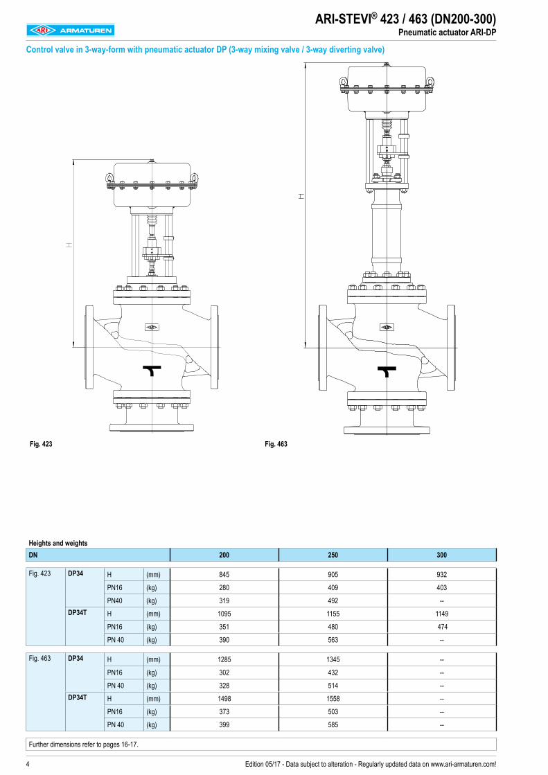
Control valve in 3-way-form with pneumatic actuator DP (3-way mixing valve / 3-way diverting valve)
Fig. 423 Fig. 463
Heights and weightsDN 200 250 300
Fig. 423 DP34 H (mm) 845 905 932
PN16 (kg) 280 409 403
PN40 (kg) 319 492 --DP34T H (mm) 1095 1155 1149
PN16 (kg) 351 480 474
PN 40 (kg) 390 563 --
Fig. 463 DP34 H (mm) 1285 1345 --
PN16 (kg) 302 432 --
PN 40 (kg) 328 514 --DP34T H (mm) 1498 1558 --
PN16 (kg) 373 503 --
PN 40 (kg) 399 585 --
Further dimensions refer to pages 16-17.

5Edition 05/17 - Data subject to alteration - Regularly updated data on www.ari-armaturen.com!
DP32 / DP33 / DP34 DP34T
Actuator data DP34 DP34T
Ø A (mm) 405
Effective diaphragm area (cm2) 800 1600
Top mounted handwheel
Ø D1 (mm) 400
H1 (mm) 442 635
Weight (kg) 17 41
Further technical data of the actuator: refer to data sheet ARI-DP.
ARI-STEVI® 423 / 463 (DN200-300)Pneumatic actuator ARI-DP
6 Edition 05/17 - Data subject to alteration - Regularly updated data on www.ari-armaturen.com!
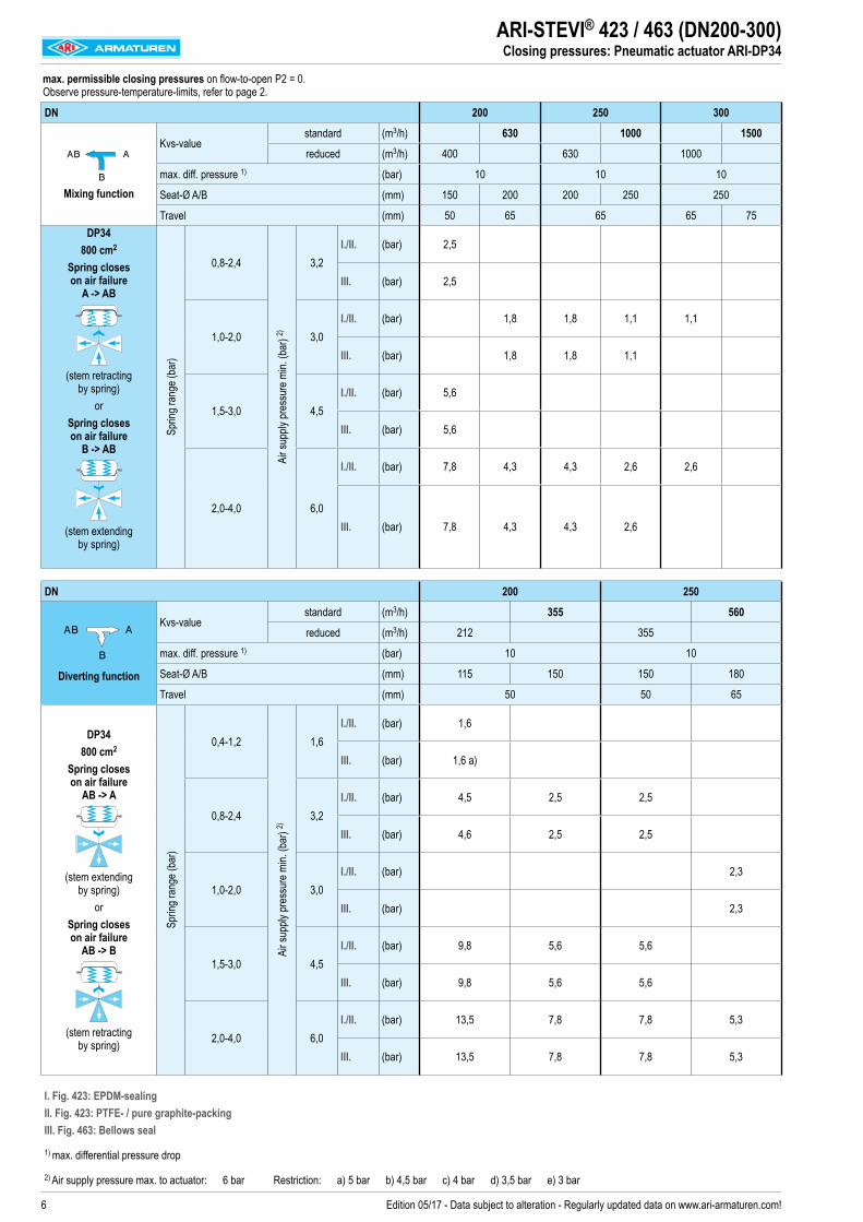
ARI-STEVI® 423 / 463 (DN200-300)Closing pressures: Pneumatic actuator ARI-DP34
max. permissible closing pressures on flow-to-open P2 = 0. Observe pressure-temperature-limits, refer to page 2.
DN 200 250 300
Mixing function
Kvs-value standard (m3/h) 630 1000 1500
reduced (m3/h) 400 630 1000
max. diff. pressure 1) (bar) 10 10 10
Seat-Ø A/B (mm) 150 200 200 250 250
Travel (mm) 50 65 65 65 75DP34
800 cm2
Spring closes on air failure
A -> AB
(stem retracting by spring)
or Spring closes on air failure
B -> AB
(stem extending by spring)
Sprin
g ran
ge (b
ar)
0,8-2,4Ai
r sup
ply pr
essu
re m
in. (b
ar) 2)
3,2
I./II. (bar) 2,5
III. (bar) 2,5
1,0-2,0 3,0I./II. (bar) 1,8 1,8 1,1 1,1
III. (bar) 1,8 1,8 1,1
1,5-3,0 4,5I./II. (bar) 5,6
III. (bar) 5,6
2,0-4,0 6,0
I./II. (bar) 7,8 4,3 4,3 2,6 2,6
III. (bar) 7,8 4,3 4,3 2,6
DN 200 250
Diverting function
Kvs-value standard (m3/h) 355 560
reduced (m3/h) 212 355
max. diff. pressure 1) (bar) 10 10
Seat-Ø A/B (mm) 115 150 150 180
Travel (mm) 50 50 65
DP34 800 cm2
Spring closes on air failure
AB -> A
(stem extending by spring)
or Spring closes on air failure
AB -> B
(stem retracting by spring)
Sprin
g ran
ge (b
ar)
0,4-1,2
Air s
upply
pres
sure
min.
(bar
) 2)
1,6I./II. (bar) 1,6
III. (bar) 1,6 a)
0,8-2,4 3,2I./II. (bar) 4,5 2,5 2,5
III. (bar) 4,6 2,5 2,5
1,0-2,0 3,0I./II. (bar) 2,3
III. (bar) 2,3
1,5-3,0 4,5I./II. (bar) 9,8 5,6 5,6
III. (bar) 9,8 5,6 5,6
2,0-4,0 6,0I./II. (bar) 13,5 7,8 7,8 5,3
III. (bar) 13,5 7,8 7,8 5,3
I. Fig. 423: EPDM-sealing II. Fig. 423: PTFE- / pure graphite-packing III. Fig. 463: Bellows seal
1) max. differential pressure drop
2) Air supply pressure max. to actuator: 6 bar Restriction: a) 5 bar b) 4,5 bar c) 4 bar d) 3,5 bar e) 3 bar

7Edition 05/17 - Data subject to alteration - Regularly updated data on www.ari-armaturen.com!
max. permissible closing pressures on flow-to-open P2 = 0. Observe pressure-temperature-limits, refer to page 2.DN 200 250 300
Mixing function
Kvs-value standard (m3/h) 630 1000 1500
reduced (m3/h) 400 630 1000
max. diff. pressure 1) (bar) 10 10 10
Seat-Ø A/B (mm) 150 200 200 250 250
Travel (mm) 50 65 65 65 75DP34T
1600 cm2
Spring closes on air failure
A -> AB
(stem retracting by spring)
or Spring closes on air failure
B -> AB
(stem extending by spring)
Sprin
g ran
ge (b
ar)
0,4-1,2
Air s
upply
pres
sure
min.
(bar
) 2)
1,6I./II. (bar) 2,5 b) 1,3 b) 1,3 b)
III. (bar) 2,5 d) 1,3 d) 1,3 d)
0,55-2,4 3,0 I./II. (bar) 1,2
0,8-2,4 3,2I./II. (bar) 6
III. (bar) 6 b)
1,0-2,0 3,0I./II. (bar) 4,3 a) 4,3 a) 2,6 a) 2,6 a)
III. (bar) 4,3 c) 4,3 c) 2,7 c)
1,5-3,0 4,5I./II. (bar) 12,2
III. (bar) 12,2 a)
2,0-4,0 6,0
I./II. (bar) 16,6 9,2 9,2 5,8 5,8
III. (bar) 16,6 9,2 9,2 5,8
DN 200 250
Diverting function
Kvs-value standard (m3/h) 355 560
reduced (m3/h) 212 355
max. diff. pressure 1) (bar) 10 10
Seat-Ø A/B (mm) 115 150 150 180
Travel (mm) 50 50 65
DP34T 1600 cm2
Spring closes on air failure
AB -> A
(stem extending by spring)
or Spring closes on air failure
AB -> B
(stem retracting by spring)
Sprin
g ran
ge (b
ar)
0,2-1,0
Air s
upply
pres
sure
min.
(bar
) 2)
1,2I./II. (bar) 1,6 b)
III. (bar) 1,6 e)
0,4-1,2 1,6I./II. (bar) 4,5 b) 2,5 b) 2,5 b) 1,7 b)
III. (bar) 4,6 d) 2,5 d) 2,5 d) 1,7 d)
0,8-2,4 3,2I./II. (bar) 10,5 6 6
III. (bar) 10,5 b) 6,1 b) 6,1 b)
1,0-2,0 3,0I./II. (bar) 5,3 a)
III. (bar) 5,3 c)
1,5-3,0 4,5I./II. (bar) 20,9 12,2 12,2
III. (bar) 21 a) 12,2 a) 12,2 a)
2,0-4,0 6I./II. (bar) 28,4 16,6 16,6 11,4
III. (bar) 28,4 16,6 16,6 11,5
ARI-STEVI® 423 / 463 (DN200-300)Closing pressures: Pneumatic actuator ARI-DP34T
I. Fig. 423: EPDM-sealing II. Fig. 423: PTFE- / pure graphite-packing III. Fig. 463: Bellows seal
1) max. differential pressure drop
2) Air supply pressure max. to actuator: 6 bar Restriction: a) 5 bar b) 4,5 bar c) 4 bar d) 3,5 bar e) 3 bar

8 Edition 05/17 - Data subject to alteration - Regularly updated data on www.ari-armaturen.com!
ARI-STEVI® 423 / 463 (DN200-300)Electric actuator ARI-PREMIO / PREMIO-Plus 2G
Heights and weightsDN 200 250 300
Fig. 423 5 kN H (mm) 843 903 --
PN16 (kg) 242 371 --
PN25/40 (kg) 281 454 --12 kN 15 kN
H (mm) 977 1057 1064
PN16 (kg) 246 375 369
PN25/40 (kg) 285 458 --25 kN H (mm) 953 1013 1064
PN16 (kg) 247 376 370
PN25/40 (kg) 286 459 --
Fig. 463 5 kN H (mm) 1265 1325 --
PN16 (kg) 264 394 --
PN25/40 (kg) 290 476 --12 kN 15 kN
H (mm) 1434 1494 --
PN16 (kg) 268 398 --
PN25/40 (kg) 294 480 --25 kN H (mm) 1434 1494 --
PN16 (kg) 269 399 --
PN25/40 (kg) 295 481 --
Further dimensions refer to pages 16-17.
Control valve in 3-way-form with electric actuator ARI-PREMIO (3-way mixing valve / 3-way diverting valve)
Fig. 423 Fig. 463
Actuator data 5 kN 12 - 25 kNA (mm) 171 210B (mm) 156 184C (mm) 50 90Ø D1 (mm) 90 130X (mm) 150 200Further technical data of the actuator: refer to data sheet ARI-PREMIO/PREMIO-Plus 2G

9Edition 05/17 - Data subject to alteration - Regularly updated data on www.ari-armaturen.com!
ARI-STEVI® 423 / 463 (DN200-300)Closing pressures: Electric actuator ARI-PREMIO / PREMIO-Plus 2G
max. permissible closing pressures on flow-to-open P2 = 0. Observe pressure-temperature-limits, refer to page 2.DN 200 250 300
Mixing function
Kvs-valuestandard (m3/h) 630 1000 1500
reduced (m3/h) 400 630 1000
max. diff. pressure 1) (bar) 10 10 10
Seat-Ø A/B (mm) 150 200 200 250 250
Travel (mm) 50 65 65 65 75
5 kN
Closing pressure I./II./III. (bar) 1,8
Operating time (s) 132
Operating speed (mm/s) 0,38
12 kN
Closing pressure I./II./III. (bar) 5,7 3,1 3,1 1,9 1,9 1,9
Operating time (s) 132 171 171 171 197
Operating speed (mm/s) 0,38
15 kN
Closing pressure I./II./III. (bar) 7,4 4 4 2,5 2,5 2,5
Operating time (s) 132 171 171 171 197
Operating speed (mm/s) 0,38
25 kN
Closing pressure I./II./III. (bar) 13 7,2 7,2 4,5 4,5 4,5
Operating time (s) 132 171 171 171 171 197
Operating speed (mm/s) 0,38
DN 200 250
Diverting function
Kvs-valuestandard (m3/h) 355 560
reduced (m3/h) 212 355
max. diff. pressure 1) (bar) 10 10
Seat-Ø A/B (mm) 115 150 150 180
Travel (mm) 50 50 65
5 kN
Closing pressure I./II./III. (bar) 3,3 1,8 1,8
Operating time (s) 132 132
Operating speed (mm/s) 0,38
12 kN
Closing pressure I./II./III. (bar) 10 5,7 5,7 3,9
Operating time (s) 132 132 171
Operating speed (mm/s) 0,38
15 kN
Closing pressure I./II./III. (bar) 12,8 7,4 7,4 5,1
Operating time (s) 132 132 171
Operating speed (mm/s) 0,38
25 kN
Closing pressure I./II./III. (bar) 22,3 13 13 9
Operating time (s) 132 132 132 171
Operating speed (mm/s) 0,38
Further operating speeds: refer to data sheet ARI-PREMIO/PREMIO-Plus 2G
I. Fig. 423: EPDM-sealing II. Fig. 423: PTFE- / pure graphite-packing III. Fig. 463: Bellows seal
1) max. differential pressure drop
Operating time [s]=Travel [mm]Operating speed [mm/s]

10 Edition 05/17 - Data subject to alteration - Regularly updated data on www.ari-armaturen.com!
ARI-STEVI® 423 / 463 (DN200-300)Electric actuator Auma SAR (MATIC)
Heights and weightsDN 200 250 300
Fig. 423 SAR 07.6 H (mm) 845 905 936PN16 (kg) 268 397 391PN40 (kg) 307 480 --
SAR 10.2 H (mm) 857 917 951PN16 (kg) 270 399 393PN40 (kg) 309 482 --
SAR 14.2 H (mm) 932 992 977PN16 (kg) 301 430 424PN40 (kg) 340 513 --
SAR 14.6 LE100 H (mm) 913 1005 --PN16 (kg) 347 476 --PN40 (kg) 386 559 --
Fig. 463 SAR 07.6 H (mm) 1290 1350 --PN16 (kg) 286 416 --PN40 (kg) 312 498 --
SAR 10.2 H (mm) 1302 1362 --PN16 (kg) 288 418 --PN40 (kg) 314 500 --
(For version with AUMA SAR Ex other heights.)Further dimensions refer to pages 16-17.
Control valve in 3-way-form with electric actuator Auma SAR (MATIC) (3-way mixing valve / 3-way diverting valve)
Fig. 423 Fig. 463
Actuator data SAR 07.6 SAR 10.2 SAR 14.2 SAR 14.6A (mm) 265 283 389 389B (mm) 249 254 336 336H1 (AUMA MATIC) (mm) 130 182 182Motor voltage: 400V 50Hz 3~ (Other voltages on request) Technical data for actuator refer to price list.

11Edition 05/17 - Data subject to alteration - Regularly updated data on www.ari-armaturen.com!
ARI-STEVI® 423 / 463 (DN200-300)Closing pressures: Electric actuator AUMA SAR
max. permissible closing pressures on flow-to-open P2 = 0. Observe pressure-temperature-limits, refer to page 2.
Fig. 423DN 200 250 300
Mixing function
Kvs-valuestandard (m3/h) 630 1000 1500
reduced (m3/h) 400 630 1000
max. diff. pressure 1) (bar) 10 10 10
Seat-Ø A/B (mm) 150 200 200 250 250
Travel (mm) 50 65 65 65 75
SAR 07.6 Output drive Form A TR 26 x 5 - LH
Closing pressure I./II.shut off (bar) 11,9 6,6 6,6 4,1 4,1 4,1
controlling 2) (bar) 5,5 2,9 2,9 1,8 2,2 2,2
Torque (Nm) 60 60 60
Operating time (50 Hz) (s) 55 71 71 71 82
Output drive (rpm) 11 11 11
SAR 10.2 Output drive Form A TR 26 x 5 - LH
Closing pressure I./II.shut off (bar) 24,8 13,9 13,9 8,8 8,8 8,8
controlling 2) (bar) 11,9 6,6 6,6 4,1 4,5 4,5
Torque (Nm) 120 120 120
Operating time (50 Hz) (s) 55 71 71 71 82
Output drive (rpm) 11 11 11
SAR 14.2 Output drive Form A TR 30 x 6 - LH
Closing pressure I./II.shut off (bar) 40 23,9 23,9 15,3 15,2 15,2
controlling 2) (bar) 20 11,1 11,1 7,1 7,4 7,4
Torque (Nm) 250 250 250
Operating time (50 Hz) (s) 63 59 59 59 68
Output drive (rpm) 8 11 11 11
SAR 14.6 with LE100.1 Output drive Form A TR 40 x 7 - LH
Closing pressure I./II.shut off (bar) 40 31,6 31,6 20,2
controlling 2) (bar) 27,7 15,5 15,5 9,8
Torque (Nm) 300 400 400
Operating time (50 Hz) (s) 54 70 70
Output drive (rpm) 8 8
Fig. 463
DN 200 250
Mixing function
Kvs-valuestandard (m3/h) 630 1000
reduced (m3/h) 400 630
max. diff. pressure 1) (bar) 10 10
Seat-Ø A/B (mm) 150 200 200 250
Travel (mm) 50 65 65
SAR 07.6 Output drive Form A TR 26 x 5 - LH
Closing pressure III.shut off (bar) 11,9 6,6 6,6 4,1
controlling 2) (bar) 5,5 3 3 1,8
Torque (Nm) 60 60
Operating time (50 Hz) (s) 55 71 71
Output drive (rpm) 11 11
SAR 10.2 Output drive Form A TR 26 x 5 - LH
Closing pressure III.shut off (bar) 18,4 10,2 10,2 6,5
controlling 2) (bar) 11,9 6,6 6,6 4,1
Torque (Nm) 90 90
Operating time (50 Hz) (s) 55 71 71
Output drive (rpm) 11 11 11
I. Fig. 423: EPDM-sealing II. Fig. 423: PTFE- / pure graphite-packing III. Fig. 463: Bellows seal
1) max. differential pressure drop 2) Restrictions through max. permissible torque of the actuator at controlling operation.

12 Edition 05/17 - Data subject to alteration - Regularly updated data on www.ari-armaturen.com!
max. permissible closing pressures on flow-to-open P2 = 0. Observe pressure-temperature-limits, refer to page 2.
Fig. 423DN 200 250
Diverting function
Kvs-valuestandard (m3/h) 355 560
reduced (m3/h) 212 355
max. diff. pressure 1) (bar) 10 10
Seat-Ø A/B (mm) 115 150 150 180
Travel (mm) 50 50 65
SAR 07.6 Output drive Form A TR 26 x 5 - LH
Closing pressure I. / II.shut off (bar) 20,5 11,9 11,9 8,2
controlling 2) (bar) 9,5 5,5 5,5 3,7
Torque (Nm) 60 60
Operating time (50 Hz) (s) 55 55 71
Output drive (rpm) 11 11
SAR 10.2 Output drive Form A TR 26 x 5 - LH
Closing pressure I. / II.shut off (bar) 40 24,8 24,8 17,2
controlling 2) (bar) 20,5 11,9 11,9 8,2
Torque (Nm) 120 120
Operating time (50 Hz) (s) 55 55 71
Output drive (rpm) 11 11
SAR 14.2 Output drive Form A TR 10 x 6 - LH
Closing pressure I. / II.shut off (bar) 40 40 40 29,6
controlling 2) (bar) 34,2 20 20 13,8
Torque (Nm) 175 250 250
Operating time (50 Hz) (s) 63 63 59
Output drive (rpm) 8 8 11
SAR 14.6 with LE100.1 Output drive Form A TR 40 x 7 - LH
Closing pressure I. / II.shut off (bar) 40 40 40 39,2
controlling 2) (bar) 40 27,7 27,7 19,2
Torque (Nm) 300 300 400
Operating time (50 Hz) (s) 54 54 70
Output drive (rpm) 8 8
Fig. 463
DN 200 250
Diverting function
Kvs-valuestandard (m3/h) 355 560
reduced (m3/h) 212 355
max. diff. pressure 1) (bar) 10 10
Seat-Ø A/B (mm) 115 150 150 180
Travel (mm) 50 50 65
SAR 07.6 Output drive Form A TR 26 x 5 - LH
Closing pressure III.shut off (bar) 20,5 11,9 11,9 8,2
controlling 2) (bar) 9,6 5,5 5,5 3,7
Torque (Nm) 60 60
Operating time (50 Hz) (s) 55 55 71
Output drive (rpm) 11 11
SAR 10.2 Output drive Form A TR 26 x 5 - LH
Closing pressure III.shut off (bar) 31,5 18,4 18,4 12,7
controlling 2) (bar) 20,5 11,9 11,9 8,2
Torque (Nm) 90 90
Operating time (50 Hz) (s) 55 55 71
Output drive (rpm) 11 11
ARI-STEVI® 423 / 463 (DN200-250)Closing pressures: Electric actuator AUMA SAR
I. Fig. 423: EPDM-sealing II. Fig. 423: PTFE- / pure graphite-packing III. Fig. 463: Bellows seal
1) max. differential pressure drop 2) Restrictions through max. permissible torque of the actuator at controlling operation.

13Edition 05/17 - Data subject to alteration - Regularly updated data on www.ari-armaturen.com!
ARI-STEVI® 423 / 463 (DN200-300)Notes

14 Edition 05/17 - Data subject to alteration - Regularly updated data on www.ari-armaturen.com!
ARI-STEVI® 423 / 463 (DN200-250)Dimensions: Standard design
Control valve in 3-way-form
Fig. 423DN200-250
(e.g.: DP34-34Tri; PREMIO 12-25kN)
Fig. 423DN200-250
(e.g.: AUMA SAR 07.6-10.2)
Fig. 463 DN200-250 M16
(e.g.: PREMIO 5-25kN; SAR 07.6 - 14.2)
Fig. 463 DN200-250 M20
(e.g.: DP34-34Tri)
DN 200 250
Dimensions
MFig. 423 (mm) M20Fig. 463 (mm) M16 M20 M16 M20
H1Fig. 423 (mm) 322 376Fig. 463 (mm) 797 723 857 783
H2Fig. 423 (mm) 98Fig. 463 (mm) 83 130 83 130
H3 Fig. 423 / 463 (mm) 380 440H4 Fig. 423 (mm) 284 344H5 Fig. 423 (mm) 130
AFig. 423 (mm) 100Fig. 463 (mm) 100 -- 100 --
n x ØBFig. 423 (mm) 2 x 16Fig. 463 (mm) 2 x 16 -- 2 x 16 --
A1Fig. 423 (mm) 150Fig. 463 (mm) -- 150 -- 150
n x ØB1Fig. 423 (mm) 4 x 16Fig. 463 (mm) -- 4 x 16 -- 4 x 16
A2 Fig. 423 (mm) 170n x M1 Fig. 423 (mm) 4 x M20T Fig. 423 (mm) 32
Face-to-face dimension FTF series 1 according to DIN EN 558L (mm) 600 730
Flanges acc. to DIN EN 1092-1/-2 Flange holes / -thickness tolerances acc. to DIN 2533/2544/2545
ØDPN16 (mm) 340 405PN25 (mm) 360 425PN40 (mm) 375 450
ØKPN16 (mm) 295 355PN25 (mm) 310 370PN40 (mm) 320 385
n x ØdPN16 (mm) 12 x 22 12 x 26PN25 (mm) 12 x 26 12 x 30PN40 (mm) 12 x 30 12 x 33
Weights
Fig. 423PN16 (kg) 235 364PN40 (kg) 274 447
Fig. 463PN16 (kg) 257 387PN40 (kg) 283 469
max. permissible thrustFig. 423 (kN) 59,1Fig. 463 (kN) 34

15Edition 05/17 - Data subject to alteration - Regularly updated data on www.ari-armaturen.com!
ARI-STEVI® 423 (DN300)Dimensions: Standard design
Control valve in 3-way-form
Fig. 423 DN300
(e.g.: DP34-34T; PREMIO 5-25kN; SAR 07.6 - 14.2)
DN 300
Dimensions
M Fig. 423 (mm) M20
H3 Fig. 423 (mm) 500
H4 Fig. 423 (mm) 348
H5 Fig. 423 (mm) 130
A2 Fig. 423 (mm) 170
M1 Fig. 423 (mm) 4 x M20
T Fig. 423 (mm) 44
Face-to-face dimension FTF series 1 according to DIN EN 558
L (mm) 850
Flanges acc. to DIN EN 1092-1/-2 Flange holes / -thickness tolerances acc. to DIN 2533/2544/2545
ØD PN16 (mm) 460
ØK PN16 (mm) 410
n x Ød PN16 (mm) 12 x 26
Weights
Fig. 423 PN16 (kg) 360
max. permissible thrust
Fig. 423 (kN) 59,1

16 Edition 05/17 - Data subject to alteration - Regularly updated data on www.ari-armaturen.com!
Pos. Sp.p. Description Fig. 12.423 Fig. 22.423 Fig. 34.423 / Fig. 35.4631 Body EN-GJL-250 , EN-JL1040 EN-GJS-400-18U-LT, EN-JS1049 GP240GH+N, 1.0619+N2 x Seat ring X20Cr13+QT, 1.4021+QT3 Bottom flange EN-GJS-400-18U-LT, EN-JS1049 GP240GH+N, 1.0619+N4 Giude bushing X20Cr13+QT, 1.4021+QT5 x Gasket Pure graphite (CrNi laminated with graphite)6 Stud 25CrMo4, 1.72187 Hexagon nut C35E, 1.11818 x Plug X20Cr13+QT, 1.4021+QT 9 x Clamping sleeve 56Si7, 1.502610 x Stem X20Cr13+QT, 1.4021+QT 12 Stuffing box housing EN-GJS-400-18U-LT, EN-JS1049 GP240GH+N, 1.0619+N13 Giude bushing X20Cr13+QT, 1.4021+QT (hardened)15 x Stem adapter X20Cr13+QT, 1.4021+QT16 x Clamping sleeve 56Si7, 1.502617 Packing ring Pure graphite19 Washer X5CrNi18-10, 1.430120 Packing box flange EN-GJS-400-18U-LT, EN-JS104921 Stud 25CrMo4, 1.721822 Hexagon nut C35E, 1.118123 Adapter flange EN-GJS-400-18U-LT, EN-JS104924 Cheese head screw 8.8 - A2B30 x Plug X20Cr13+QT, 1.4021+QT31 x Plug X20Cr13+QT, 1.4021+QT32 x Castle nut C35E, 1.118133 Cotter pin A4
Stem sealings Fig. 42317 x Packing ring PTFE17 x Packing ring Pure graphite120 x EPDM-sealing EPDM / X20Cr13+QT, 1.4021+QT
└ Spare parts
ARI-STEVI® 423 (DN200-250)Parts: Standard design
II. PTFE- / pure graphite-packing
I. EPDM-sealing
Plug design: Diverting plug

17Edition 05/17 - Data subject to alteration - Regularly updated data on www.ari-armaturen.com!
ARI-STEVI® 463 (DN200-250)Parts: Standard design
III. PTFE-packing / Pure graphite-packing
III. Stainless steel bellows seal with EPDM-sealing
Plug design: Diverting plug
Pos. Sp.p. Description Fig. 12.463 Fig. 22.463 Fig. 34.423 / Fig. 35.4631 Body EN-GJL-250 , EN-JL1040 EN-GJS-400-18U-LT, EN-JS1049 GP240GH+N, 1.0619+N2 x Seat ring X20Cr13+QT, 1.4021+QT3 Bottom flange EN-GJS-400-18U-LT, EN-JS1049 GP240GH+N, 1.0619+N4 Giude bushing X20Cr13+QT, 1.4021+QT5 x Gasket Pure graphite (CrNi laminated with graphite)6 Stud 25CrMo4, 1.72187 Hexagon nut C35E, 1.11818 x Plug X20Cr13+QT, 1.4021+QT 9 x Clamping sleeve 56Si7, 1.502612 Stuffing box housing EN-GJS-400-18U-LT, EN-JS1049 GP240GH+N, 1.0619+N13 Giude bushing X20Cr13+QT, 1.4021+QT (hardened)15 x Stem adapter X20Cr13+QT, 1.4021+QT16 x Clamping sleeve 56Si7, 1.50262501 Bellows housing EN-GJS-400-18U-LT, EN-JS1049 GP240GH+N, 1.0619+N2502 Mounting bonnet EN-GJS-400-18U-LT, EN-JS1049 GP240GH+N, 1.0619+N2503 x Stem- / Bellows unit X20Cr13+QT, 1.4021+QT / X6CrNiTi18-10, 1.45412505 Giude bushing X20Cr13+QT, 1.4021+QT (hardened)2506 x Gasket Pure graphite (CrNi laminated with graphite)2507 Stud 25CrMo4, 1.72182508 Hexagon nuts C35E, 1.11812509 Straight pin St2510 x Packing ring Pure graphite2512 Washer X5CrNi18-10, 1.43012517 x Screw joint X8CrNiS18-9, 1.430527 x Gasket Pure graphite (CrNi laminated with graphite)28 Stud 25CrMo4, 1.721829 Hexagon nut C35E, 1.118130 x Plug X20Cr13+QT, 1.4021+QT31 x Plug X20Cr13+QT, 1.4021+QT32 x Castle nut C35E, 1.118133 Cotter pin A4
Stem sealings Fig. 4632510 x Packing ring Pure graphite120 x EPDM-sealing EPDM / X20Cr13+QT, 1.4021+QT
└ Spare parts

18 Edition 05/17 - Data subject to alteration - Regularly updated data on www.ari-armaturen.com!
Pos. Sp.p. Description Fig. 22.423
1 Body EN-GJS-400-18U-LT, EN-JS1049
2 x Seat ring X20Cr13+QT, 1.4021+QT
3 Bottom flange EN-GJS-400-18U-LT, EN-JS1049
5 x Gasket Pure graphite (CrNi laminated with graphite)
6 Stud 25CrMo4, 1.7218
7 Hexagon nut C35E, 1.1181
8 x Plug X20Cr13+QT, 1.4021+QT
9 x Spring-type straight pin X10CrNi18-8, 1.4310
10 x Stem X20Cr13+QT, 1.4021+QT
12 Stuffing box housing P250 GH, 1.0460
13 Giude bushing X20Cr13+QT, 1.4021+QT (hardened)
17 x Packing ring PTFE or Pure graphite
19 x Washer X5CrNi18-10, 1.4301
20 Packing box flange EN-GJS-400-18U-LT, EN-JS1049
21 Stud 25CrMo4, 1.7218
22 Hexagon nut C35E, 1.1181
26 Hexagon nut 17H-A4G
34 Stud 25CrMo4, 1.7218
35 Hexagon nut C35E, 1.1181
36 x Gasket Pure graphite (CrNi laminated with graphite)
44 Packing box flange EN-GJS-400-18U-LT, EN-JS1049
45 Stud 25CrMo4, 1.7218
Stem sealings Fig. 42317 x Packing ring PTFE
17 x Packing ring Pure graphite
120 x EPDM-sealing EPDM / X20Cr13+QT, 1.4021+QT└ Spare parts
ARI-STEVI® 423 (DN300)Parts: Standard design
II. PTFE- / pure graphite-packing I. EPDM-sealing

19Edition 05/17 - Data subject to alteration - Regularly updated data on www.ari-armaturen.com!
ARI-STEVI® 423 / 463 (DN200-300)Notes

20 Edition 05/17 - Data subject to alteration - Regularly updated data on www.ari-armaturen.com!
ARI-STEVI® 423 / 463 (DN200-300)Sizing
myValve® - Your Valve Sizing-Program.myValve® is a powerful software tool that not only helps you size your system components; it also gives you instant access to all other data about the selected product, such as order information, spare parts drawings, operating instructions, data sheets, etc., whenever you need it.
Contents: Module ARI-control valves STEVI-calculation- Sizing (calculation of flow quantity Kv, volume flow Q, pressure drop Δp, sound level and selecting the valve.)
Media: Integrated media-databank (more than 160 media) with conditions:- Vapours / gases- Steam (saturated and superheated)- Liquids
Special features: - Project administration of the calculation and product data incl. spare part drawings concerning to project and tag number.- Direct output or calculation and product data in PDF format.- Product data could be taken for a direct order.- SI- and ANSI-units with direct conversion to another databank.- Settings with over pressure or absolute pressure.- All ARI valves are integrated in a databank.- Direct access concerning to the product on data sheets, operating instructions, pressure-temperature-diagram and spare part
drawings - Operation in company networks possible (no complex installations on individually PC‘s necessary).- Extensive catalogue extending over several product groups.
System Requirements: Windows operating systems, Linux, etc.
Technology for the Future.G E R M A N Q U A L I T Y V A L V E S
ARI-Armaturen Albert Richter GmbH & Co. KG, D-33750 Schloß Holte-Stukenbrock, Tel. +49 52 07 / 994-0, Telefax +49 52 07 / 994-158 or 159 Internet: http://www.ari-armaturen.com E-mail: [email protected]

Data sheet 453001 englisch (english)Edition 06/17 - Data subject to alteration - Regularly updated data on www.ari-armaturen.com!
ARI-STEVI® 453 Electric actuator ARI-PREMIO 2,2-15 kN ARI-PREMIO-Plus 2G 2,2-15 kN• Enclosure IP 65• 2 torque switches• Handwheel• Additional options available, e.g. potentiometer
Page 2
ARI-STEVI® 453with electric actuators
Feedwater control valve with pump spill backDN 25 - 100
Fig. 453
Features: • Compact design• Precision guided stem• Burnished stem• Tapered seat ring• 2 screwed seatrings• Reducible kvs-values• Rangeability 30 : 1• Post guided plug• EPDM sealing• Travel indicator

2 Edition 06/17 - Data subject to alteration - Regularly updated data on www.ari-armaturen.com!
ARI-STEVI® 453 (DN25 - 100)Ventil: Technical data
Figure Nominal pressure Material Nominal diameter Information / restriction of technical rules need to be observed!A production permission acc. to TRB 801 No. 45 is available. The engineer, designing a system or a plant, is responsible for the selection of the correct valve. Resistance and fitness must be verified, contact manufacturer for information (refer to Product overview and Resistance list).
35.453 PN40 1.0619+N DN25 - 100
Other materials and versions on request.
Stem sealingFig. 453 standard
I. EPDM sealing-10°C to 180°C
Pressure-temperature-ratings Intermediate values for max. permissible operational pressures can be determined by linear interpolation of the given temperature / pressure chart.
acc. to manufacturers standard -10°C to 120°C 150°C 180°C1.0619+N PN40 (bar) 40 38,1 36,2

3Edition 06/17 - Data subject to alteration - Regularly updated data on www.ari-armaturen.com!
ARI-STEVI® 453 (DN25 - 100)Plug design / Operation
Plug design standard Guiding Rangeability
• Perforated plug, metal seat
- Leakage class IV acc. to DIN EN 60534-4- Flow characteristic: AB --> A equal percentage AB --> B linear
Stem and port guiding 30 : 1
Operation
The feedwater control valve regulates the flow of feedwater to the steam boiler. It is controlled by a level controller. The target of the control is to keep the level in the boiler constant. The feedwater control valve is normally built into the feed water pressure line. If the water level drops in the boiler, the electrical actuator PREMIO-Plus 2G adjustes a perforated plug in the valve. If the water level in the boiler rises, the perforated plug closes the seat.Once the feed water amount to the boiler falls below a certain amount, a further perforated plug opens the bypass valve. It ensures that the minimum amount, required for cooling and lubrication of the feed water pump, is always available.
Necessary data for sizing
Medium: Feed waterTemperature: ........................ [°C]Inlet pressure: ........................ [bar(g)] (Pump pressure )After-pressure: ........................ [bar(g)] (Boiler pressure)Boiler capacity: ........................ [t/h]Pump delivery rate: ........................ [m³/h]Recirculation flowrat: ........................ [m³/h]
Actuator PREMIO-Plus 2G:Voltage: ........................Options: ........................
Closing pressures refer to page 5.

4 Edition 06/17 - Data subject to alteration - Regularly updated data on www.ari-armaturen.com!
ARI-STEVI® 453 (DN25 - 100)Electric actuator ARI-PREMIO / PREMIO-Plus 2G
Heights and weightsDN 25 32 40 50 65 80 100
Fig. 453 2,2 kN H (mm) 563 589 595 593 -- -- --PN40 (kg) 14 18 22 25 -- -- --
5 kN H (mm) 563 589 595 593 629 645 664PN40 (kg) 15 19 22 25 34 45 63
12 kN H (mm) 737 763 769 767 803 819 838PN40 (kg) 20 23 27 30 39 49 68
15 kN H (mm) -- -- -- -- 803 819 838PN40 (kg) -- -- -- -- 39 49 68
Further dimensions refer to page 6.
Feedwater control valve with pump spill back with electric actuator ARI-PREMIO-Plus 2G
Fig. 453
Actuator data 2,2 - 5 kN 12 - 15 kNA (mm) 171 210B (mm) 156 184C (mm) 50 90Ø D1 (mm) 90 130X (mm) 150 200Technical data for actuator refer to data sheet ARI-PREMIO/PREMIO-Plus 2G

5Edition 06/17 - Data subject to alteration - Regularly updated data on www.ari-armaturen.com!
max. permissible closing pressures on flow-to-open and P2 = 0. Note restrictions through pressure-temperature-ratings, refer to page 3.
DN 25 32 40 50
Straight throughKvs-value (m3/h) 1 1,6 2,5 4 6,3 2,5 4 6,3 10 4 6,3 10 16 6,3 10 16 25
Seat-Ø A (mm) 27 27 31 27 31 41 27 31 41 51
BypassKvs-value (m3/h) 0,1 0,16 0,25 0,40 0,63 0,25; 0,4 0,63 1,0 0,4 0,63 1,0 1,6 0,63 1,0 1,6 2,5
Seat-Ø B (mm) 8 8 8 13 8 13
max. differential pressure 1) (bar) 40 40 40 40
Travel (mm) 20 20 20 20
2,2 kN
Closing pressure I. (bar) 15,4 15,4 11,6 15,4 11,6 6,4 15,4 11,6 6,4 4
Operating time (s) 53 53 53 53
Operating speed 2) (mm/s) 0,38
5 kN
Closing pressure I. (bar) 38,5 38,5 29,2 38,5 29,2 16,6 38,5 29,2 16,6 10,6
Operating time (s) 53 53 53 53
Operating speed (mm/s) 0,38
12 kN
Closing pressure I. (bar) 40 40 40 40 27,2
Operating time (s) 53 53 53 53
Operating speed (mm/s) 0,38
DN 65 80 100
Straight throughKvs-value (m3/h) 10 16 25 40 16 25 40 63 25 40 63 100
Seat-Ø A (mm) 41 41 51 66 41 51 66 81 51 66 81 101
BypassKvs-value (m3/h) 1,0 1,6 2,5 4 1,6 2,5 4,0 6,3 2,5 4,0 6,3 10
Seat-Ø B (mm) 25 25 25
max. differential pressure 1) (bar) 40 40 40
Travel (mm) 30 30 30
5 kN
Closing pressure I. (bar) 16,5 16,5 10,5 6,2 16,5 10,5 6,2 4 10,5 6,2 4 2,5
Operating time (s) 79 79 79
Operating speed (mm/s) 0,38
12 kN
Closing pressure I. (bar) 40 40 27,1 16,1 40 27,1 16,1 10,6 27,1 16,1 10,6 6,8
Operating time (s) 79 79 79
Operating speed (mm/s) 0,38
15 kN
Closing pressure I. (bar) 40 40 34,3 20,4 40 34,3 20,4 13,4 34,3 20,4 13,4 8,6
Operating time (s) 79 79 79
Operating speed (mm/s) 0,38
Further operating speeds: refer to data sheet ARI-PREMIO / PREMIO-Plus 2G
ARI-STEVI® 453 (DN25 - 100)Closing pressures: Electric actuator ARI-PREMIO / PREMIO-Plus 2G
I. EPDM sealing
1) Max. differential pressure drop with flow 2) Based on a frequency of 50Hz the control speed and power consumption of the synchronous motors PREMIO 2,2kN are 20% higher at frequency of 60 Hz.
Operating time [s]=Travel [mm]Operating speed [mm/s]

6 Edition 06/17 - Data subject to alteration - Regularly updated data on www.ari-armaturen.com!
Feedwater control valve with pump spill back
Fig. 453
ARI-STEVI® 453 (DN25 - 100)Dimensions: Standard design
DN 25 32 40 50 65 80 100
DimensionsM Fig. 453 (mm) M10 M14 x 1,5H1 Fig. 453 (mm) 115 141 147 154 181 197 216H2 Fig. 453 (mm) 75 80 90 100 120 130 150H3 Fig. 453 (mm) 83A Fig. 453 (mm) 100ØB Fig. 453 (mm) 2 x Ø 16
Face-to-face dimension FTF series 1 according to DIN EN 558L (mm) 160 180 200 230 290 310 350
Flanges acc. to DIN EN 1092-1/-2 ØD PN40 (mm) 115 140 150 165 185 200 235ØK PN40 (mm) 85 100 110 125 145 160 190n x Ød PN40 (mm) 4 x 14 4 x 18 4 x 18 4 x 18 8 x 18 8 x 18 8 x 22
WeightsFig. 453 PN40 (kg) 9 13 16 19 28 39 57
max. perm. closing forcesFig. 453 (kN) 12,7 29,5

7Edition 06/17 - Data subject to alteration - Regularly updated data on www.ari-armaturen.com!
Pos. Ers. Description Fig. 35.453 1 Body GP240GH+N, 1.0619+N2 x Seat ring X20Cr13+QT, 1.4021+QT (hardened)7 Mounting bonnet GP240GH+N, 1.0619+N8 Guide bushing X20Cr13+QT, 1.4021+QT (hardened)9 x Gasket Pure graphite (CrNi laminated with graphite)10 Studs 25CrMo4, 1.721811 Hexagon nuts C35E, 1.118117 x Sealing ring Cu / Soft iron21 Hexagon nuts 17H-A2G31 x Plug X20Cr13+QT, 1.4021+QT34 x Seat ring X20Cr13+QT, 1.4021+QT (hardened)40 x Plug X20Cr13+QT, 1.4021+QT41 x Stem X20Cr13+QT, 1.4021+QT64 Grub screw A2
Stem sealing Fig. 45356 x EPDM sealing X8CrNiS18-9, 1.4305 / EPDM
└ Spare parts
ARI-STEVI® 453 (DN25 - 100)Parts: Standard design

8 Edition 06/17 - Data subject to alteration - Regularly updated data on www.ari-armaturen.com!
ARI-STEVI® 453 (DN25 - 100)Constructions
Options: Adapter flange (to make compatible to other design)
DN25 - 32 DN40 / 50 / 80
DN 25 32
DimensionsH5 (mm) 109 115Connection Bypass 90°-elbow 1/2“
DN 40 50 80
DimensionsL1 (mm) 115 115 155H5 (mm) 111 106 190Flange connection Bypass DN15 PN40 DN40 PN40
Technology for the Future. G E R M A N Q U A L I T Y V A L V E S
ARI-Armaturen Albert Richter GmbH & Co. KG, D-33750 Schloß Holte-Stukenbrock, Tel. +49 52 07 / 994-0, Telefax +49 52 07 / 994-158 or 159 Internet: http://www.ari-armaturen.com E-mail: [email protected]
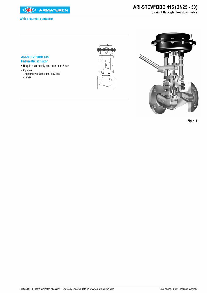
Edition 02/14 - Data subject to alteration - Regularly updated data on www.ari-armaturen.com! Data sheet 415001 englisch (english)
ARI-STEVI® BBD 415 Pneumatic actuator• Required air supply pressure max. 6 bar• Options:
- Assembly of additional devices - Lever
ARI-STEVI®BBD 415 (DN25 - 50) Straight through blow down valve
With pneumatic actuator
Fig. 415

2 Edition 02/14 - Data subject to alteration - Regularly updated data on www.ari-armaturen.com!
ARI-STEVI®BBD 415 (DN25 - 50)Technical data
Capacity chart
Steam boiler pressure (barg)
Hot w
ater f
low (k
g/s)
Figure Nominal pressure Material Nominal diameter Information / restriction of technical rules need to be observed!A production permission acc. to TRB 801 No. 45 is available.The engineer, designing a system or a plant, is responsible for the selection of the correct valve.Resistance and fitness must be verified (contact manufacturer for information, refer to Product overview and Resistance list).
35.415 PN40 1.0619+N DN 25 - 50
Other materials and versions on request.
Stem sealingFig. 415 standard
I. PTFE-V-ring unit-10°C to 240°C
Pressure-temperature-ratings Intermediate values for max. permissible operational pressures can be determined by linear interpolation of the given temperature / pressure chart.
acc. to manufacturers standard -10°C to 120°C 150°C 200°C 250°C 300°C 350°C 400°C 450°C
1.0619+N PN40 (bar) 40 38,1 35 32 28 25,7 23,8 13,1

3Edition 02/14 - Data subject to alteration - Regularly updated data on www.ari-armaturen.com!
ARI-STEVI®BBD 415 (DN25 - 50)Technical data / Capacity chart
Plug design standard Guiding
Isolation plug with marginal seat, stellited, metal seat
- Leakage class 1 acc. to DIN 3230 T3 / BN Stem
Auxiliary engergy
• Max. permissible air supply pressure: 6 bar• Air supply acc. to DIN IEC 60654-2 • Water free from dirt and corrosives, max. temperature +80°C
Accessories
Lever Solenoid valve
Limit switch Air set including gauge (in combination with solenoid valve)

4Edition 02/14 - Data subject to alteration - Regularly updated data on www.ari-armaturen.com!
DN 25 32 40 50Seat-Ø (mm) 22 27 37 47Travel (mm) 8 7 10 13
Kvs-valuestandard (m3/h) 6,4 6,4 14,7 14,7
Face-to-face dimension FTF series 1 according to DIN EN 558L (mm) 160 180 200 230
Flanges acc. to DIN EN 1092-1/-2 Flange holes / -thickness tolerances acc. to DIN 2533/2544/2545Ø D
PN40(mm) 115 140 150 165
Ø K (mm) 85 100 110 125n x Ø d1 (mm) 4 x 14 4 x 18 4 x 18 4 x 18
DimensionsH (mm) 336 336 364 370Ø A (mm) 168 168 250 250G (inch) 1/4“ 1/4“ 1/4“ 1/4“
Weight35.415 (kg) 13 15 18,3 21,5
ARI-STEVI®BBD 415 (DN25 - 50)Dimensions: Standard design
Straight through blow down valve
Fig. 415 DN 25 - 32
Fig. 415 DN 40 - 50
Air supply
Air supply

ARI-STEVI®BBD 415 (DN25 - 50)Parts: Standard design
Pos. Sp.p. Description Fig. 35.415 DN 25 - 32 Fig. 35.415 DN 40 - 501 Body GP240GH+N, 1.0619+N1.2 Seat ring Stellit 213 x Plug X6CrNiMoTi17-12-2, 1.4571 / Stellit 64 x Locking pin X10CrNi18-8, 1.43105 x Stem X20Cr13+QT, 1.4021+QT7 Mounting bonnet GP240GH+N, 1.0619+N8 Giude bushing X20Cr13+QT, 1.4021+QT (hardened)9 x Gasket Novaphit SSTC (CrNi laminated with graphite)10 Stud 25CrMo4, 1.721811 Hexagon nuts C35E, 1.118112 x V-ring unit PTFE14 x Washer X5CrNi18-10, 1.430115 x Compression spring X10CrNi18-8, 1.431016 x Bush PTFE (strengthened)17 x Gasket Cu / Soft iron19 x Screw joint X8CrNiS18-9, 1.4305 / PTFE21 Hexagon nuts 17H - A4G22 x Locking pin X10CrNi18-8, 1.431050.1 Stem DP X20Cr13+QT, 1.4021+QT50.3.1 x Stem guiding X20Cr13+QT, 1.4021+QT50.3.2 x Guide bush PTFE + 25%C50.3.3 x O-ring (Stem) NBR 7050.3.4 x O-ring (Guiding) NBR 7050.3.5 x Scraper PTFE GF50.4 Retaining ring -- FSt - A2B50.5 Disc spring -- C75S, 1.124850.7 Diaphragm housing EN-JS1049, EN-GJS-400-18U-LT DD13+QT, 1.0335+QT50.8 Bush -- X20Cr13+QT, 1.4021+QT50.9 Diaphragm flange 11SMnPb30+C, 1.0718+C DD13+QT, 1.0335+QT50.10 x Diaphragm 50 NBR 25350.11 Diaphragm plate 11SMnPb30+C, 1.0718+C50.14 Collar nut with sealing ring 8 - A2B50.15 x Compression spring SH50.18 Diaphragm hood EN-JS1049, EN-GJS-400-18U-LT DD13+QT, 1.0335+QT50.19 Screwed cap PP50.20 Hexagon nut 8 - A2G50.21 Hexagon screw 8.8 - A2G50.22 Washer St - A2G50.23 Hexagon screw 8.8 - A2G50.24 Eye nut -- C15, 1.0401 - A4G50.90 Traverse S235JR, 1.003750.91 Cheese head screw 8.8 - A2B50.92 Screwed cap PP51 Distance column X20Cr13+QT, 1.4021+QT52 Hexagon nut 8 - A2B53 2-ear clamp St54 Lock washer pair St55 Travel indicator X20Cr13+QT, 1.4021+QT57 Washer disc C75S, 1.124858 Parallel pin A1
└ Spare parts
5Edition 02/14 - Data subject to alteration - Regularly updated data on www.ari-armaturen.com!

6 Edition 02/14 - Data subject to alteration - Regularly updated data on www.ari-armaturen.com!
ARI-STEVI®BBD 415 (DN25 - 50)Capacity chart
Please indicate when ordering:- Figure-No. - Nominal diameter- Nominal pressure- Stem sealing- Special design / accessoriesExample:Figure 35.415; Nominal diameter DN40; Nominal pressure PN40; Stem sealing: PTFE-V-ring unit
Capacity chart
on flow-to-close
Spring closes on air failure
(NC)(Extended stem
on air failure)
DNSpring range Filling volume
(bar) (l)
25 1,55 - 2,50 0,25
32 1,55 - 2,40 0,25
40 1,6 - 2,4 1,1
50 1,4 - 2,4 1,1
Medium pressure (bar) Medium pressure (bar)
Air s
upply
pres
sure
min.
(bar
)
Air s
upply
pres
sure
min.
(bar
)
Technology for the Future. G E R M A N Q U A L I T Y V A L V E S
ARI-Armaturen Albert Richter GmbH & Co. KG, D-33750 Schloß Holte-Stukenbrock, Tel. +49 52 07 / 994-0, Telefax +49 52 07 / 994-158 or 159 Internet: http://www.ari-armaturen.com E-mail: [email protected]