Embed Size (px)
Citation preview

ARIB STD-T64-C.S0029-B v1.0
Test Application Specification (TAS) for High Rate Packet Data
Air Interface
Refer to "Industrial Property Rights (IPR)" in the preface of ARIB STD-T64 for Related Industrial
Property Rights. Refer to "Notice" in the preface of ARIB STD-T64 for Copyrights

Original Specification 1
This standard, ARIB STD-T64-C.S0029-B v1.0, was prepared by 3GPP2-WG of Association of 2
Radio Industries and Businesses (ARIB) based upon the 3GPP2 specification, C.S0029-B v1.0. 3
4
Modification to the original specification 5
None. 6
7
Notes 8
None. 9
10
3GPP2 C.S0029-B
Version 1.0
Date: March 31, 2008
Test Application Specification (TAS) for High Rate Packet Data Air Interface
COPYRIGHT 2008.
3GPP2 and its Organizational Partners claim copyright in this document and individual Organizational Partners may copyright and issue documents or standards publications in individual Organizational Partner's name based on this document. Requests for reproduction of this document should be directed to the 3GPP2 Secretariat at [email protected]. Requests to reproduce individual Organizational Partner's documents should be directed to that Organizational Partner. See www.3gpp2.org for more information.

(No text)
C.S0029-B v1.0 CONTENTS
i
FOREWORD................................................................................................................... xiii 1
REFERENCES................................................................................................................. xv 2
1 Overview .....................................................................................................................1-1 3
1.1 Scope of This Document ........................................................................................1-1 4
1.2 Objectives..............................................................................................................1-1 5
1.3 Requirements Language ........................................................................................1-1 6
1.4 Protocol Overview ..................................................................................................1-1 7
1.5 Basic Protocol Numbers.........................................................................................1-3 8
1.6 Document Organization.........................................................................................1-3 9
1.7 Acronyms ..............................................................................................................1-5 10
1.8 Notation ................................................................................................................1-6 11
2 Forward Test Application Protocol (FTAP) Specification................................................2-1 12
2.1 Overview................................................................................................................2-1 13
2.2 Data Encapsulation...............................................................................................2-1 14
2.3 Primitives and Public Data ....................................................................................2-1 15
2.3.1 Commands ......................................................................................................2-1 16
2.3.2 Indications ......................................................................................................2-2 17
2.3.3 Public Data......................................................................................................2-2 18
2.4 Basic Protocol Numbers.........................................................................................2-2 19
2.5 Protocol Data Unit .................................................................................................2-2 20
2.6 Test Statistics........................................................................................................2-2 21
2.6.1 Access Terminal Requirements ........................................................................2-2 22
2.6.2 Access Network Requirements .........................................................................2-3 23
2.7 Procedures ............................................................................................................2-3 24
2.7.1 Test Parameter Configuration ..........................................................................2-4 25
2.7.1.1 Access Terminal Requirements ..................................................................2-4 26
2.7.1.1.1 Access Terminal Configuration Initialization.........................................2-4 27
2.7.1.1.2 Access Terminal Configuration for Lost or Closed Connection ..............2-4 28
2.7.1.2 Access Network Requirements ...................................................................2-5 29
2.7.1.2.1 Access Network Test Statistics and Parameters Initialization................2-5 30
2.7.2 Access Terminal Statistics Collection and Retrieval..........................................2-5 31
2.7.2.1 Access Terminal Requirements ..................................................................2-5 32
C.S0029-B v1.0
CONTENTS
ii
2.7.2.1.1 Statistics Initialization .........................................................................2-6 1
2.7.2.2 Access Network Requirements ...................................................................2-6 2
2.7.3 FTAP Test Packet Transmission and Reception................................................2-7 3
2.7.3.1 Access Terminal Requirements ..................................................................2-7 4
2.7.3.2 Access Network Requirements ...................................................................2-7 5
2.7.4 FTAP Loop Back Packet Transmission and Reception ......................................2-7 6
2.7.4.1 Access Terminal Requirements ..................................................................2-7 7
2.7.4.2 Access Network Requirements ...................................................................2-8 8
2.7.5 DRC Channel Transmission ............................................................................2-9 9
2.7.5.1 Access Terminal Requirements ..................................................................2-9 10
2.7.6 ACK Channel Transmission...........................................................................2-10 11
2.7.6.1 Access Terminal Requirements ................................................................2-10 12
2.8 Message Formats ................................................................................................2-10 13
2.8.1 FTAPParameterAssignment ...........................................................................2-10 14
2.8.1.1 DRCValueFixedMode Parameter Record ..................................................2-11 15
2.8.1.2 DRCCoverFixedMode Parameter Record ..................................................2-11 16
2.8.1.3 ACKChannelBitFixedMode Parameter Record ..........................................2-12 17
2.8.1.4 LoopBackMode Parameter Record............................................................2-12 18
2.8.2 FTAPParameterComplete ...............................................................................2-13 19
2.8.3 FTAPStatsClearRequest.................................................................................2-13 20
2.8.4 FTAPStatsClearResponse...............................................................................2-14 21
2.8.5 FTAPStatsGetRequest....................................................................................2-14 22
2.8.6 FTAPStatsGetResponse .................................................................................2-15 23
2.8.6.1 IdleASPStats Statistics Record.................................................................2-15 24
2.8.6.2 ConnectedSSStats Statistics Record ........................................................2-16 25
2.8.6.3 FirstSyncCCPktStats Statistics Record ....................................................2-17 26
2.9 FTAP Packet Formats ..........................................................................................2-18 27
2.9.1 FTAP Test Packet...........................................................................................2-18 28
2.9.2 FTAP Loop Back Packet.................................................................................2-19 29
2.10 Protocol Numeric Constants..............................................................................2-21 30
2.11 Interface to Other Protocols...............................................................................2-22 31
2.11.1 Commands..................................................................................................2-22 32
C.S0029-B v1.0 CONTENTS
iii
2.11.2 Indications...................................................................................................2-22 1
3 Reverse Test Application Protocol (RTAP) Specification ................................................3-1 2
3.1 Overview................................................................................................................3-1 3
3.2 Data Encapsulation...............................................................................................3-1 4
3.3 Primitives and Public Data ....................................................................................3-1 5
3.3.1 Commands ......................................................................................................3-1 6
3.3.2 Indications ......................................................................................................3-1 7
3.3.3 Public Data......................................................................................................3-2 8
3.4 Basic Protocol Numbers.........................................................................................3-2 9
3.5 Protocol Data Unit .................................................................................................3-2 10
3.6 Test Statistics........................................................................................................3-2 11
3.6.1 Access Network Requirements .........................................................................3-2 12
3.7 Procedures ............................................................................................................3-2 13
3.7.1 Test Parameter Configuration ..........................................................................3-2 14
3.7.1.1 Access Terminal Requirements ..................................................................3-2 15
3.7.1.1.1 Access Terminal Configuration Initialization.........................................3-3 16
3.7.1.1.2 Access Terminal Configuration for Closed or Lost Connection ..............3-3 17
3.7.1.1.3 Access Terminal Test Parameter Initialization ......................................3-3 18
3.7.1.2 Access Network Requirements ...................................................................3-3 19
3.7.1.2.1 Access Network Test Statistics Initialization .........................................3-4 20
3.7.2 RTAP Packet Transmission and Reception .......................................................3-4 21
3.7.2.1 Access Terminal Requirements ..................................................................3-4 22
3.7.2.1.1 Generation and Transmission ..............................................................3-4 23
3.7.2.1.2 Rate Selection ......................................................................................3-5 24
3.7.2.2 Access Network Requirements ...................................................................3-5 25
3.8 Message Formats...................................................................................................3-6 26
3.8.1 RTAPParameterAssignment .............................................................................3-6 27
3.8.1.1 RTAPTestPktEnable Parameter Record.......................................................3-7 28
3.8.1.2 PacketRateMode Parameter Record............................................................3-7 29
3.8.2 RTAPParameterComplete .................................................................................3-8 30
3.9 RTAP Packet Formats ............................................................................................3-9 31
3.9.1 RTAP Test Packet.............................................................................................3-9 32
C.S0029-B v1.0
CONTENTS
iv
3.9.2 RTAP Fill Packet ............................................................................................3-10 1
3.10 Protocol Numeric Constants..............................................................................3-11 2
3.11 Interface to Other Protocols...............................................................................3-11 3
3.11.1 Commands..................................................................................................3-11 4
3.11.2 Indications ..................................................................................................3-11 5
4 Forward Enhanced Test Application Protocol (FETAP) Specification ............................4-1 6
4.1 Overview ...............................................................................................................4-1 7
4.2 Data Encapsulation ..............................................................................................4-1 8
4.3 Primitives and Public Data ....................................................................................4-2 9
4.3.1 Commands......................................................................................................4-2 10
4.3.2 Indications ......................................................................................................4-2 11
4.3.3 Public Data .....................................................................................................4-2 12
4.4 Basic Protocol Numbers ........................................................................................4-2 13
4.5 Protocol Data Unit.................................................................................................4-2 14
4.6 Test Statistics .......................................................................................................4-2 15
4.6.1 Access Terminal Requirements........................................................................4-2 16
4.6.2 Access Network Requirements.........................................................................4-3 17
4.7 Procedures ............................................................................................................4-4 18
4.7.1 Test Parameter Configuration..........................................................................4-4 19
4.7.1.1 Access Terminal Requirements ..................................................................4-4 20
4.7.1.1.1 Access Terminal Configuration Initialization ........................................4-5 21
4.7.1.1.2 Access Terminal Configuration for Lost or Closed Connection..............4-5 22
4.7.1.2 Access Network Requirements ...................................................................4-6 23
4.7.1.2.1 Access Network Test Statistics and Parameters Initialization ...............4-6 24
4.7.2 Access Terminal Statistics Collection and Retrieval .........................................4-6 25
4.7.2.1 Access Terminal Requirements ..................................................................4-6 26
4.7.2.1.1 Statistics Initialization .........................................................................4-7 27
4.7.2.2 Access Network Requirements ...................................................................4-7 28
4.7.3 PL_0_1_2 FETAP Test Packet Transmission and Reception ..............................4-8 29
4.7.3.1 Access Terminal Requirements ..................................................................4-8 30
4.7.3.2 Access Network Requirements ...................................................................4-8 31
C.S0029-B v1.0 CONTENTS
v
4.7.4 PL_0_1 FETAP Loop Back Packet and PL_2 FETAP Loop Back Packet 1
Transmission and Reception ...............................................................................4-8 2
4.7.4.1 Access Terminal Requirements ..................................................................4-8 3
4.7.4.2 Access Network Requirements ...................................................................4-9 4
4.7.5 DRC Channel Transmission...........................................................................4-12 5
4.7.5.1 Access Terminal Requirements ................................................................4-12 6
4.7.6 ACK Channel Transmission ...........................................................................4-12 7
4.7.6.1 Access Terminal Requirements ................................................................4-12 8
4.8 Message Formats.................................................................................................4-12 9
4.8.1 FETAPParameterAssignment .........................................................................4-12 10
4.8.1.1 DRCValueFixedMode Parameter Record...................................................4-13 11
4.8.1.2 DRCCoverFixedMode Parameter Record...................................................4-14 12
4.8.1.3 ACKChannelBitFixedMode Parameter Record ..........................................4-14 13
4.8.1.4 LoopBackMode Parameter Record............................................................4-15 14
4.8.1.5 ACKChannelModulationTypeFixedMode Parameter Record ......................4-15 15
4.8.2 FETAPParameterComplete .............................................................................4-16 16
4.8.3 FETAPStatsClearRequest...............................................................................4-16 17
4.8.4 FETAPStatsClearResponse.............................................................................4-17 18
4.8.5 FETAPStatsGetRequest..................................................................................4-17 19
4.8.6 FETAPStatsGetResponse ...............................................................................4-18 20
4.8.6.1 IdleASPStats Statistics Record .................................................................4-19 21
4.8.6.2 ConnectedSSStats Statistics Record ........................................................4-19 22
4.8.6.3 FirstSyncCCPktStats Statistics Record.....................................................4-20 23
4.9 FETAP Packet Formats ........................................................................................4-21 24
4.9.1 PL_0_1_2 FETAP Test Packet .........................................................................4-21 25
4.9.2 PL_0_1 FETAP Loop Back Packet ...................................................................4-22 26
4.9.3 PL_2 FETAP Loop Back Packet.......................................................................4-24 27
4.10 Protocol Numeric Constants ..............................................................................4-26 28
4.11 Interface to Other Protocols ...............................................................................4-27 29
4.11.1 Commands ..................................................................................................4-27 30
4.11.2 Indications...................................................................................................4-27 31
5 Reverse Enhanced Test Application Protocol (RETAP) Specification .............................5-1 32
5.1 Overview................................................................................................................5-1 33
C.S0029-B v1.0
CONTENTS
vi
5.2 Data Encapsulation ..............................................................................................5-1 1
5.3 Primitives and Public Data ....................................................................................5-2 2
5.3.1 Commands......................................................................................................5-2 3
5.3.2 Indications ......................................................................................................5-2 4
5.3.3 Public Data .....................................................................................................5-2 5
5.4 Basic Protocol Numbers ........................................................................................5-2 6
5.5 Protocol Data Unit.................................................................................................5-2 7
5.6 Test Statistics .......................................................................................................5-2 8
5.6.1 Access Terminal Requirements........................................................................5-2 9
5.6.2 Access Network Requirements.........................................................................5-3 10
5.7 Procedures ............................................................................................................5-3 11
5.7.1 Test Parameter Configuration..........................................................................5-4 12
5.7.1.1 Access Terminal Requirements ..................................................................5-4 13
5.7.1.1.1 Access Terminal Configuration Initialization ........................................5-5 14
5.7.1.1.2 Access Terminal Configuration for Closed or Lost Connection..............5-5 15
5.7.1.1.3 Access Terminal Test Parameter Initialization ......................................5-5 16
5.7.1.2 Access Network Requirements ...................................................................5-6 17
5.7.1.2.1 Access Network Test Statistics Initialization.........................................5-6 18
5.7.2 Access Terminal Statistics Collection and Retrieval .........................................5-6 19
5.7.2.1 Access Terminal Requirements ..................................................................5-6 20
5.7.2.1.1 Statistics Initialization .........................................................................5-7 21
5.7.2.2 Access Network Requirements ...................................................................5-7 22
5.7.3 PL_0_1 RETAP Packet and PL_2 RETAP Packet Transmission and 23
Reception ...........................................................................................................5-7 24
5.7.3.1 Access Terminal Requirements ..................................................................5-7 25
5.7.3.1.1 Generation and Transmission..............................................................5-7 26
5.7.3.1.2 Rate Selection......................................................................................5-9 27
5.7.3.1.3 Payload Size Selection..........................................................................5-9 28
5.7.3.2 Access Network Requirements .................................................................5-10 29
5.8 Message Formats ................................................................................................5-12 30
5.8.1 RETAPParameterAssignment.........................................................................5-12 31
5.8.1.1 RETAPTestPktEnable Parameter Record ..................................................5-13 32
C.S0029-B v1.0 CONTENTS
vii
5.8.1.2 PacketRateMode Parameter Record..........................................................5-14 1
5.8.1.3 PacketPayloadSizeMode Parameter Record...............................................5-14 2
5.8.1.4 EnhancedAccessChannelRateMode Parameter Record .............................5-16 3
5.8.1.5 BurstPeriodMode Parameter Record.........................................................5-17 4
5.8.1.6 BurstSizeMode Parameter Record ............................................................5-18 5
5.8.2 RETAPParameterComplete.............................................................................5-19 6
5.8.3 RETAPStatsClearRequest...............................................................................5-19 7
5.8.4 RETAPStatsClearResponse ............................................................................5-20 8
5.8.5 RETAPStatsGetRequest .................................................................................5-20 9
5.8.6 RETAPStatsGetResponse ...............................................................................5-21 10
5.8.6.1 Vi(SPL_2Rev)Stats Statistics Record..............................................................5-22 11
5.9 RETAP Packet Formats........................................................................................5-23 12
5.9.1 PL_0_1 RETAP Test Packet ............................................................................5-23 13
5.9.2 PL_0_1 RETAP Fill Packet ..............................................................................5-24 14
5.9.3 PL_2 RETAP Test Packet ................................................................................5-25 15
5.10 Protocol Numeric Constants ..............................................................................5-27 16
5.11 Interface to Other Protocols ...............................................................................5-27 17
5.11.1 Commands ..................................................................................................5-27 18
5.11.2 Indications...................................................................................................5-27 19
6 Forward Multicarrier Test Application Protocol (FMCTAP) Specification .......................6-1 20
6.1 Overview................................................................................................................6-1 21
6.2 Data Encapsulation...............................................................................................6-1 22
6.3 Primitives and Public Data ....................................................................................6-2 23
6.3.1 Commands ......................................................................................................6-2 24
6.3.2 Indications ......................................................................................................6-2 25
6.3.3 Public Data......................................................................................................6-2 26
6.4 Basic Protocol Numbers.........................................................................................6-2 27
6.5 Protocol Data Unit .................................................................................................6-2 28
6.6 Test Statistics........................................................................................................6-2 29
6.6.1 Access Terminal Requirements ........................................................................6-2 30
6.6.2 Access Network Requirements .........................................................................6-3 31
6.7 Procedures ............................................................................................................6-4 32
C.S0029-B v1.0
CONTENTS
viii
6.7.1 Test Parameter Configuration..........................................................................6-5 1
6.7.1.1 Access Terminal Requirements ..................................................................6-5 2
6.7.1.1.1 Access Terminal Configuration Initialization ........................................6-6 3
6.7.1.1.2 Access Terminal Configuration for Lost or Closed Connection..............6-7 4
6.7.1.2 Access Network Requirements ...................................................................6-7 5
6.7.1.2.1 Access Network Test Statistics and Parameters Initialization ...............6-7 6
6.7.2 Access Terminal Statistics Collection and Retrieval .........................................6-8 7
6.7.2.1 Access Terminal Requirements ..................................................................6-8 8
6.7.2.1.1 Statistics Initialization .........................................................................6-9 9
6.7.2.2 Access Network Requirements ...................................................................6-9 10
6.7.3 PL_0_1_2_3 FMCTAP Test Packet Transmission and Reception .....................6-10 11
6.7.3.1 Access Terminal Requirements ................................................................6-10 12
6.7.3.2 Access Network Requirements .................................................................6-10 13
6.7.4 PL_0_1 FMCTAP Loop Back Packet, PL_2 FETAP Loop Back Packet and 14
PL_3 FMCTAP Loop Back Packet Transmission and Reception..........................6-10 15
6.7.4.1 Access Terminal Requirements ................................................................6-10 16
6.7.4.2 Access Network Requirements .................................................................6-12 17
6.7.5 DRC Channel Transmission ..........................................................................6-15 18
6.7.5.1 Access Terminal Requirements ................................................................6-15 19
6.7.6 ACK Channel Transmission...........................................................................6-15 20
6.7.6.1 Access Terminal Requirements ................................................................6-15 21
6.8 Message Formats ................................................................................................6-16 22
6.8.1 FMCTAPParameterAssignment ......................................................................6-16 23
6.8.1.1 DRCValueFixedMode Parameter Record ..................................................6-17 24
6.8.1.2 DRCCoverFixedMode Parameter Record ..................................................6-18 25
6.8.1.3 ACKChannelBitFixedMode Parameter Record ..........................................6-19 26
6.8.1.4 LoopBackMode Parameter Record............................................................6-19 27
6.8.1.5 ACKChannelModulationTypeFixedMode Parameter Record......................6-20 28
6.8.2 FMCTAPParameterComplete..........................................................................6-25 29
6.8.3 FMCTAPStatsClearRequest............................................................................6-26 30
6.8.4 FMCTAPStatsClearResponse .........................................................................6-26 31
6.8.5 FMCTAPStatsGetRequest ..............................................................................6-27 32
C.S0029-B v1.0 CONTENTS
ix
6.8.6 FMCTAPStatsGetResponse ............................................................................6-28 1
6.8.6.1 IdleASPStats Statistics Record .................................................................6-28 2
6.8.6.2 ConnectedSSStats Statistics Record ........................................................6-29 3
6.8.6.3 FirstSyncCCPktStats Statistics Record.....................................................6-30 4
6.9 FMCTAP Packet Formats .....................................................................................6-32 5
6.9.1 PL_0_1_2_3 FMCTAP Test Packet...................................................................6-32 6
6.9.2 PL_0_1 FMCTAP Loop Back Packet ................................................................6-33 7
6.9.3 PL_2 FMCTAP Loop Back Packet....................................................................6-35 8
6.9.4 PL_3 FMCTAP Loop Back Packet....................................................................6-38 9
6.10 Protocol Numeric Constants ..............................................................................6-40 10
6.11 Interface to Other Protocols ...............................................................................6-40 11
6.11.1 Commands ..................................................................................................6-40 12
6.11.2 Indications...................................................................................................6-40 13
7 Reverse MULTICARRIER Test Application Protocol (RMCTAP) Specification .................7-1 14
7.1 Overview................................................................................................................7-1 15
7.2 Data Encapsulation...............................................................................................7-1 16
7.3 Primitives and Public Data ....................................................................................7-2 17
7.3.1 Commands ......................................................................................................7-2 18
7.3.2 Indications ......................................................................................................7-2 19
7.3.3 Public Data......................................................................................................7-2 20
7.4 Basic Protocol Numbers.........................................................................................7-2 21
7.5 Protocol Data Unit .................................................................................................7-2 22
7.6 Test Statistics........................................................................................................7-2 23
7.6.1 Access Terminal Requirements ........................................................................7-2 24
7.6.2 Access Network Requirements .........................................................................7-3 25
7.7 Procedures ............................................................................................................7-4 26
7.7.1 Test Parameter Configuration ..........................................................................7-5 27
7.7.1.1 Access Terminal Requirements ..................................................................7-5 28
7.7.1.1.1 Access Terminal Configuration Initialization.........................................7-6 29
7.7.1.1.2 Access Terminal Configuration for Closed or Lost Connection ..............7-6 30
7.7.1.1.3 Access Terminal Test Parameter Initialization ......................................7-6 31
7.7.1.2 Access Network Requirements ...................................................................7-7 32
C.S0029-B v1.0
CONTENTS
x
7.7.1.2.1 Access Network Test Statistics Initialization.........................................7-7 1
7.7.2 Access Terminal Statistics Collection and Retrieval .........................................7-7 2
7.7.2.1 Access Terminal Requirements ..................................................................7-7 3
7.7.2.1.1 Statistics Initialization .........................................................................7-8 4
7.7.2.2 Access Network Requirements ...................................................................7-8 5
7.7.3 PL_0_1 RMCTAP Packet, PL_2 RMCTAP Packet and PL_3 RMCTAP Packet 6
Transmission and Reception...............................................................................7-9 7
7.7.3.1 Access Terminal Requirements ..................................................................7-9 8
7.7.3.1.1 Generation and Transmission..............................................................7-9 9
7.7.3.1.2 Rate Selection....................................................................................7-11 10
7.7.3.1.3 Payload Size Selection........................................................................7-11 11
7.7.3.2 Access Network Requirements .................................................................7-12 12
7.8 Message Formats ................................................................................................7-16 13
7.8.1 RMCTAPParameterAssignment......................................................................7-16 14
7.8.1.1 RMCTAPTestPktEnable Parameter Record ...............................................7-16 15
7.8.1.2 PacketRateMode Parameter Record..........................................................7-17 16
7.8.1.3 PacketPayloadSizeMode Parameter Record ..............................................7-18 17
7.8.1.4 EnhancedAccessChannelRateMode Parameter Record.............................7-19 18
7.8.1.5 BurstPeriodMode Parameter Record ........................................................7-20 19
7.8.1.6 BurstSizeMode Parameter Record............................................................7-21 20
7.8.2 RMCTAPParameterComplete .........................................................................7-22 21
7.8.3 RMCTAPStatsClearRequest ...........................................................................7-24 22
7.8.4 RMCTAPStatsClearResponse .........................................................................7-25 23
7.8.5 RMCTAPStatsGetRequest ..............................................................................7-25 24
7.8.6 RMCTAPStatsGetResponse............................................................................7-26 25
7.8.6.1 Vi(SPL_2Rev)Stats Statistics Record .............................................................7-27 26
7.8.6.2 Vij(SPL_3Rev)Stats Statistics Record.............................................................7-28 27
7.9 RMCTAP Packet Formats.....................................................................................7-30 28
7.9.1 PL_0_1 RMCTAP Test Packet .........................................................................7-30 29
7.9.2 PL_0_1 RMCTAP Fill Packet...........................................................................7-32 30
7.9.3 PL_2 RMCTAP Test Packet.............................................................................7-32 31
7.9.4 PL_3 RMCTAP Test Packet.............................................................................7-34 32
C.S0029-B v1.0 CONTENTS
xi
7.10 Protocol Numeric Constants ..............................................................................7-35 1
7.11 Interface to Other Protocols ...............................................................................7-35 2
7.11.1 Commands ..................................................................................................7-35 3
7.11.2 Indications...................................................................................................7-35 4
8 Broadcast Test Application Protocol (BTAP) Specification ............................................8-1 5
8.1 Overview................................................................................................................8-1 6
8.2 Data Encapsulation...............................................................................................8-1 7
8.3 Primitives and Public Data ....................................................................................8-1 8
8.3.1 Commands ......................................................................................................8-1 9
8.3.2 Indications ......................................................................................................8-1 10
8.3.3 Public Data......................................................................................................8-1 11
8.4 Basic Protocol Numbers.........................................................................................8-2 12
8.5 Protocol Data Unit .................................................................................................8-2 13
8.6 Test Statistics........................................................................................................8-2 14
8.6.1 Access Terminal Requirements ........................................................................8-2 15
8.7 Procedures ............................................................................................................8-2 16
8.7.1 Test Parameter Configuration ..........................................................................8-2 17
8.7.1.1 Access Terminal Requirements ..................................................................8-2 18
8.7.1.1.1 Access Terminal Configuration Initialization.........................................8-3 19
8.7.1.2 Access Network Requirements ...................................................................8-3 20
8.7.2 Access Terminal Statistics Collection and Retrieval..........................................8-3 21
8.7.2.1 Access Terminal Requirements ..................................................................8-3 22
8.7.2.1.1 Statistics Initialization..........................................................................8-3 23
8.7.2.2 Access Network Requirements ...................................................................8-4 24
8.7.3 BTAP Test Packet Transmission and Reception................................................8-4 25
8.7.3.1 Access Terminal Requirements ..................................................................8-4 26
8.7.3.2 Access Network Requirements ...................................................................8-4 27
8.8 Message Formats...................................................................................................8-5 28
8.8.1 BTAPParameterAssignment .............................................................................8-5 29
8.8.1.1 BTAPTestPktEnable Parameter Record.......................................................8-5 30
8.8.2 BTAPParameterComplete .................................................................................8-6 31
8.8.3 BTAPStatsClearRequest...................................................................................8-6 32

C.S0029-B v1.0
CONTENTS
xii
8.8.4 BTAPStatsClearResponse ................................................................................8-7 1
8.8.5 BTAPStatsGetRequest .....................................................................................8-7 2
8.8.6 BTAPStatsGetResponse ...................................................................................8-8 3
8.8.6.1 BTAPTestPktStats Statistics Record...........................................................8-8 4
8.9 BTAP Packet Formats............................................................................................8-9 5
8.9.1 BTAP Test Packet ............................................................................................8-9 6
8.10 Protocol Numeric Constants..............................................................................8-11 7
8.11 Interfaces to Other Protocols .............................................................................8-12 8
8.11.1 Commands..................................................................................................8-12 9
8.11.2 Indications ..................................................................................................8-12 10
9 Test application Example flow Diagrams .....................................................................9-1 11
9.1 Overview ...............................................................................................................9-1 12
9.2 Forward Link Performance Tests ...........................................................................9-1 13
9.2.1 Statistics Collection and Retrieval at the Access Terminal ...............................9-1 14
9.2.2 Subtype 0 Physical Layer Protocol Throughput and Packet Error Rate 15
Measurement .....................................................................................................9-2 16
9.2.3 Subtype 3 Physical Layer Protocol Throughput and Packet Error Rate 17
Measurement .....................................................................................................9-4 18
9.3 Computation of Forward Link Performance ...........................................................9-5 19
9.4 Reverse Link Performance Tests ............................................................................9-7 20
9.4.1 Subtype 0 Physical Layer Protocol Throughput and Packet Error Rate 21
Measurement .....................................................................................................9-7 22
9.4.2 Subtype 2 Physical Layer Protocol Throughput and Packet Error Rate 23
Measurement .....................................................................................................9-8 24
9.4.3 Subtype 3 Physical Layer Protocol Throughput and Packet Error Rate 25
Measurement ...................................................................................................9-10 26
9.5 Computation of Reverse Link Performance ..........................................................9-11 27
9.6 Broadcast Link Performance ...............................................................................9-14 28
9.7 Computation of Broadcast Link Performance ......................................................9-15 29
C.S0029-B v1.0
FIGURES
xiii
Figure 2.2-1 FTAP Packet Encapsulation........................................................................2-1 1
Figure 2.9-1 SSRG Implementation of the Sequence 1/(1 + x + x15 ) .............................2-18 2
Figure 3.2-1 RTAP Packet Encapsulation .......................................................................3-1 3
Figure 4.2-1 FETAP Packet Encapsulation .....................................................................4-2 4
Figure 4.9-1 SSRG Implementation of the Sequence 1/(1 + x + x15 ) .............................4-22 5
Figure 5.2-1 RETAP Packet Encapsulation .....................................................................5-2 6
Figure 5.9-1 SSRG Implementation of the Sequence 1/(1 + x + x15 ) .............................5-26 7
Figure 6.2-1 FMCTAP Packet Encapsulation ..................................................................6-2 8
Figure 6.9-1 SSRG Implementation of the Sequence 1/(1 + x + x15 ) .............................6-33 9
Figure 7.2-1 RMCTAP Packet Encapsulation ..................................................................7-2 10
Figure 7.9-1 SSRG Implementation of the Sequence 1/(1 + x + x15 ) .............................7-33 11
Figure 8.2-1 BTAP Packet Encapsulation .......................................................................8-1 12
Figure 8.9-1 SSRG Implementation of the Sequence 1/(1 + x + x15 ) .............................8-11 13
Figure 9.2-1. Flow Diagram for Control Channel Packet Error Rate Measurement..........9-2 14
Figure 9.2-2. Flow Diagram for Subtype 0 Physical Layer Protocol Forward Link 15
Throughput and PER Measurement..........................................................................9-3 16
Figure 9.2-3. Flow Diagram for Subtype 3 Physical Layer Protocol Forward Link 17
Throughput and PER Measurement..........................................................................9-4 18
Figure 9.4-1. Flow Diagram for Subtype 0 Physical Layer Protocol Reverse Link 19
Throughput and PER Measurements ........................................................................9-8 20
Figure 9.4-2. Flow Diagram for Subtype 2 Physical Layer Protocol Reverse Link 21
Throughput and PER Measurements ........................................................................9-9 22
Figure 9.4-3. Flow Diagram for Subtype 3 Physical Layer Protocol Reverse Link 23
Throughput and PER Measurements ......................................................................9-10 24
Figure 9.6-1 Flow Diagram for Broadcast Link PER Measurement................................9-14 25
C.S0029-B v1.0
TABLES
xiv
TABLE 1
List of Acronyms ............................................................................................................ 1-5 2
Encoding of RTC Rates................................................................................................... 3-8 3
Encoding of Subtype 0 and 1 Physical Layer Protocol RTC Rates ................................. 5-14 4
Encoding of Subtype 2 Physical Layer Protocol RTC Payload Sizes ............................... 5-15 5
Encoding of Subtype 1 and 2 Physical Layer Protocol Enhanced Access Channel AC 6
Rates...................................................................................................................... 5-17 7
Encoding of Subtype 0 and 1 Physical Layer Protocol RTC Rates ................................. 7-18 8
Encoding of Subtype 2 and 3 Physical Layer Protocol RTC Payload Sizes ..................... 7-19 9
Encoding of Subtype 1, 2 and 3 Physical Layer Protocol Enhanced Access Channel 10
AC Rates ................................................................................................................ 7-20 11
12

C.S0029-B v1.0
TABLES
xv
No text. 1
2
C.S0029-B v1.0
FOREWORD
xvi
(This foreword is not part of this Standard) 1
This standard was prepared by Technical Specification Group C of the Third Generation 2
Partnership Project 2 (3GPP2). This standard is a companion to the cdma2000®1 high rate 3
packet data standards. This specification provides a set of procedures that the access 4
terminal and the access network can use to conduct the access terminal minimum 5
performance tests in a factory/laboratory environment. It also allows measurements of 6
certain forward and reverse link performances in a field environment.7
1 cdma2000® is the trademark for the technical nomenclature for certain specifications and standards of the Organizational Partners (OPs) of 3GPP2. Geographically (and as of the date of publication), cdma2000® is a registered trademark of the Telecommunications Industry Association (TIA-USA) in the United States.

C.S0029-B v1.0
xvii
No text. 1
C.S0029-B v1.0
REFERENCES
xviii
The following standards and specifications contain provisions, which, through reference in 1
this text, constitute provisions of this standard. At the time of publication, the editions 2
indicated were valid. All standards are subject to revision, and parties to agreements based 3
on this standard are encouraged to investigate the possibility of applying the most recent 4
editions of the standards indicated below. 5
6
NORMATIVE REFERENCES 7
8
[1] 3GPP2 C.S0024-B Version 2, cdma2000 High Rate Packet Data Air Interface 9
Specification, 2007. 10
[2] Reserved. 11
[3] Reserved. 12
[4] Reserved. 13
[5] 3GPP2 C.S0054-A Version 1, cdma2000 High Rate Broadcast-Multicast Packet Data 14
Air Interface Specification, 2006. 15
[6] Reserved. 16
[7] RFC 1661, The Point-to-Point Protocol, July 1994. 17
INFORMATIVE REFERENCES 18
[8] 3GPP2 C.R1001-F version 1.0, Administration of Parameter Value Assignments for 19
cdma2000 Spread Spectrum Standards, 2007. 20

C.S0029-B v1.0
REFERENCES
xix
No text. 1

C.S0029-B v1.0
1-1
1 OVERVIEW 1
1.1 Scope of This Document 2
These technical requirements form a compatibility standard for test applications in 3
cdma2000 high rate packet data systems. These requirements ensure that a compliant 4
access terminal and a compliant access network can interoperate to execute tests in 5
meeting the objectives stated in 1.2. While the details of the tests are beyond the scope of 6
this document, an informative section illustrating some examples is provided. 7
This specification is primarily oriented toward requirements necessary for the design and 8
implementation of access terminals. As a result, detailed procedures are specified for 9
access terminals to ensure a uniform response to all access networks. Access network 10
procedures, however, are specified only to the extent necessary for compatibility with those 11
specified for the access terminal. 12
1.2 Objectives 13
The Test Application Protocol, Enhanced Test Application Protocol, and Broadcast Test 14
Application Protocol specified in this document meet the following objectives. They provide 15
a set of procedures that the access terminal and the access network can use, 16
• To conduct the access terminal minimum performance and signaling conformance 17
tests in a factory/laboratory environment. 18
• To conduct measurement of certain forward and reverse link performances in a field 19
environment. 20
1.3 Requirements Language 21
Compatibility, as used in connection with this standard, is understood to mean: Any access 22
terminal can obtain service through any access network conforming to this standard. 23
Conversely, all access networks conforming to this standard can service access terminals. 24
“Shall” and “shall not” identify requirements to be followed strictly to conform to the 25
standard and from which no deviation is permitted. “Should” and “should not” indicate that 26
one of several possibilities is recommended as particularly suitable, without mentioning or 27
excluding others, that a certain course of action is preferred but not necessarily required, 28
or that (in the negative form) a certain possibility or course of action is discouraged but not 29
prohibited. “May” and “need not” indicate a course of action permissible within the limits of 30
the standard. “Can” and “cannot” are used for statements of possibility and capability, 31
whether material, physical, or causal. 32
1.4 Protocol Overview 33
The following is a brief overview of the Test Application Protocol, the Enhanced Test 34
Application Protocol, and the Broadcast Test Application Protocol. A complete description of 35
the components can be found in the following sections. 36
The Test Application Protocol is specified in terms of two independent protocols: 37
C.S0029-B v1.0
1-2
1. Forward Test Application Protocol (FTAP): This protocol specifies the procedures and 1
messages to control the Forward Traffic Channel and to configure reverse channels 2
associated with the Forward Traffic Channel. It specifies generation and 3
transmission of test packets sent on the Forward and Reverse Traffic Channels for 4
the purpose of testing the Forward Traffic Channel. It also specifies statistics 5
collection procedures for certain statistics as seen at the access terminal. This 6
protocol operates with the Subtype 0 Physical Layer Protocol [1]. 7
2. Reverse Test Application Protocol (RTAP): This protocol specifies the procedures and 8
messages to control and configure the Reverse Traffic Channel. It generates test 9
packets sent on the Reverse Traffic Channel for testing the channel. This protocol 10
operates with the Subtype 0 Physical Layer Protocol [1]. This protocol does not 11
operate with Subtype 2 Reverse Traffic Channel MAC Protocol. 12
The Enhanced Test Application Protocol is specified in terms of two independent protocols: 13
1. Forward Enhanced Test Application Protocol (FETAP): This protocol specifies the 14
procedures and messages to control the Forward Traffic Channel and to configure 15
reverse channels associated with the Forward Traffic Channel. It specifies 16
generation and transmission of test packets sent on the Forward and Reverse 17
Traffic Channels for the purpose of testing the Forward Traffic Channel. It also 18
specifies statistics collection procedures for certain statistics as seen at the access 19
terminal. This protocol operates with the Subtype 0 Physical Layer Protocol, 20
Subtype 1 Physical Layer Protocol, or Subtype 2 Physical Layer Protocol [1]. 21
2. Reverse Enhanced Test Application Protocol (RETAP): This protocol specifies the 22
procedures and messages to control and configure the Reverse Traffic Channel. It 23
generates test packets sent on the Reverse Traffic Channel for testing the channel. 24
This protocol operates with the Subtype 0 Physical Layer Protocol, Subtype 1 25
Physical Layer Protocol, or Subtype 2 Physical Layer Protocol [1]. This protocol does 26
not operate with Subtype 2 Reverse Traffic Channel MAC Protocol. 27
The Multicarrier Test Application Protocol is specified in terms of two independent 28
protocols: 29
1. Forward Multicarrier Test Application Protocol (FMCTAP): This protocol specifies the 30
procedures and messages to control the Forward Traffic Channel and to configure 31
reverse channels associated with the Forward Traffic Channel for Multicarrier and 32
Single-carrier operation. It specifies generation and transmission of test packets 33
sent on the Forward and Reverse Traffic Channels for the purpose of testing the 34
Forward Traffic Channel. It also specifies statistics collection procedures for certain 35
statistics as seen at the access terminal. This protocol operates with the Subtype 0 36
Physical Layer Protocol, Subtype 1 Physical Layer Protocol, Subtype 2 Physical 37
Layer Protocol or Subtype 3 Physical Layer Protocol [1]. 38
2. Reverse Multicarrier Test Application Protocol (RMCTAP): This protocol specifies the 39
procedures and messages to control and configure the Reverse Traffic Channel for 40
Multicarrier and Single-carrier operation. It generates test packets sent on the 41
Reverse Traffic Channel for testing the channel. This protocol operates with the 42
Subtype 0 Physical Layer Protocol, Subtype 1 Physical Layer Protocol, Subtype 2 43
C.S0029-B v1.0
1-3
Physical Layer Protocol or Subtype 3 Physical Layer Protocol [1]. This protocol does 1
not operate with Subtype 2 Reverse Traffic Channel MAC Protocol. 2
The Broadcast Test Application Protocol (BTAP) [5] specifies the procedures and messages 3
to control and configure the Broadcast Channel. It specifies the generation and 4
transmission of test packets sent on the Broadcast Channel for the purpose of testing the 5
Broadcast Channel. This protocol operates with the Subtype 0 Physical Layer Protocol [1]. 6
1.5 Basic Protocol Numbers 7
The Test Application Protocol shall use the application subtype value [8] of 0x0003. 8
The Enhanced Test Application Protocol shall use the application subtype value [8] of 9
0x000A. 10
The Broadcast Test Application Protocol shall use the application subtype value [8] of 11
0x000B. 12
The Multicarrier Test Application Protocol shall use the application subtype value [8] of 13
0x000E. 14
1.6 Document Organization 15
This document is organized into the following sections: 16
• Section 1 Overview: This section describes the document scope and objectives as 17
well as document organization, list of acronyms and notations. 18
• Section 2 Forward Test Application Protocol (FTAP) Specifications: This section 19
describes the procedures and messages of the Forward Test Application Protocol. 20
• Section 3 Reverse Test Application Protocol (RTAP) Specifications: This section 21
describes the procedures and messages of the Reverse Test Application Protocol. 22
• Section 4 Forward Enhanced Test Application Protocol (FETAP) Specifications: This 23
section describes the procedures and messages of the Forward Enhanced Test 24
Application Protocol. 25
• Section 5 Reverse Enhanced Test Application Protocol (RETAP) Specifications: This 26
section describes the procedures and messages of the Reverse Enhanced Test 27
Application Protocol. 28
• Section 6 Forward Multicarrier Test Application Protocol (FMCTAP) Specifications: 29
This section describes the procedures and messages of the Forward Multicarrier 30
Test Application Protocol. 31
• Section 7 Reverse Multicarrier Test Application Protocol (RMCTAP) Specifications: 32
This section describes the procedures and messages of the Reverse Multicarrier Test 33
Application Protocol. 34
• Section 8 Broadcast Test Application Protocol (BTAP) Specifications: This section 35
describes the procedures and messages of the Broadcast Test Application Protocol. 36

C.S0029-B v1.0
1-4
• Section 9 Test Application Example Flow Diagrams: This section describes some 1
examples using the procedures and messages specified in the document. This is for 2
informational purpose only. 3
C.S0029-B v1.0
1-5
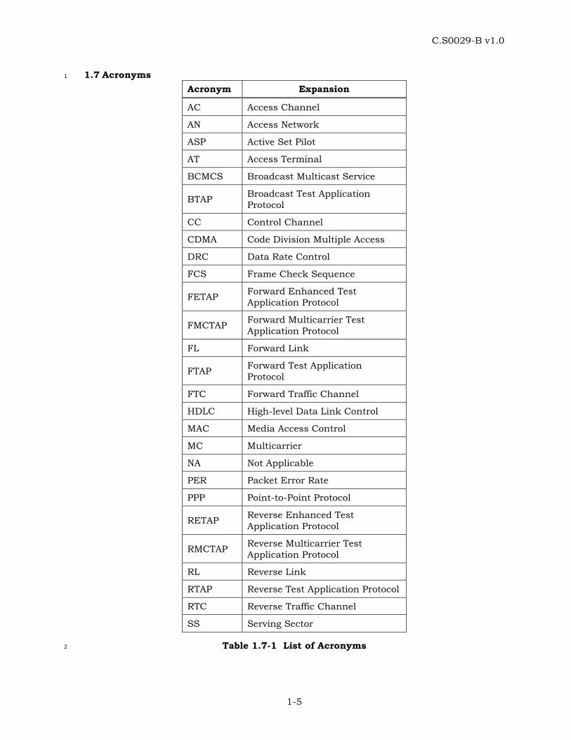
1.7 Acronyms 1
Acronym Expansion
AC Access Channel
AN Access Network
ASP Active Set Pilot
AT Access Terminal
BCMCS Broadcast Multicast Service
BTAP Broadcast Test Application Protocol
CC Control Channel
CDMA Code Division Multiple Access
DRC Data Rate Control
FCS Frame Check Sequence
FETAP Forward Enhanced Test Application Protocol
FMCTAP Forward Multicarrier Test Application Protocol
FL Forward Link
FTAP Forward Test Application Protocol
FTC Forward Traffic Channel
HDLC High-level Data Link Control
MAC Media Access Control
MC Multicarrier
NA Not Applicable
PER Packet Error Rate
PPP Point-to-Point Protocol
RETAP Reverse Enhanced Test Application Protocol
RMCTAP Reverse Multicarrier Test Application Protocol
RL Reverse Link
RTAP Reverse Test Application Protocol
RTC Reverse Traffic Channel
SS Serving Sector
Table 1.7-1 List of Acronyms 2

C.S0029-B v1.0
1-6
1.8 Notation 1
A[i] The (i+1)th element of array A. The first element of the array is A[0]. 2
A[i,j] The (j+1)th element of (i+1)th row of matrix A. The first element of the 3
matrix is A[0,0]. 4
x mod y Indicates the remainder after dividing x by y: x mod y = x – (y × 5
⎣x/y⎦). 6
Min(a,b) The minimum of the two arguments a and b. 7
8
C.S0029-B v1.0
2-1
2 FORWARD TEST APPLICATION PROTOCOL (FTAP) SPECIFICATION 1
2.1 Overview 2
The Forward Test Application Protocol (FTAP) provides the procedures and messages used 3
by the access terminal and the access network to: 4
• Control FTAP test configurations at both the access terminal and the access 5
network. 6
• Generate FTAP Test Packets at the access network for transmission on the Forward 7
Traffic Channel and process the received packets at the access terminal. 8
• Generate and transmit information about the received FTAP packets at the access 9
terminal through FTAP Loop Back Packets. 10
• Transmit configured ACK Channel bits, DRC values and DRC covers. 11
• Collect statistics on the changes in the serving sector as seen at the access terminal 12
in the Idle State and the Connected State. 13
• Collect statistics on the number of successfully received first Synchronous Control 14
Channel packets. 15
2.2 Data Encapsulation 16
In the transmit direction, the FTAP generates test packets and forwards them to the stream 17
layer. 18
In the receive direction the FTAP receives test packets from the stream layer and processes 19
them. 20
Figure 2.2-1 illustrates the relationship between the FTAP packets and the Stream Layer 21
payload. 22
StreamLayer
payload
FTAPpacket
23
Figure 2.2-1 FTAP Packet Encapsulation 24
2.3 Primitives and Public Data 25
2.3.1 Commands 26
This protocol does not define any commands. 27
C.S0029-B v1.0
2-2
2.3.2 Indications 1
This protocol returns the following indications: 2
• LoopbackSyncLost 3
2.3.3 Public Data 4
Subtype for this application. 5
2.4 Basic Protocol Numbers 6
FTAP is a protocol associated with the Test Application. This protocol shall use the 7
application subtype value for the Test Application as specified in 1.5. 8
2.5 Protocol Data Unit 9
The transmission unit of this protocol is an FTAP packet. The FTAP packet size is 10
determined by the lower layers that are negotiated during session configuration. 11
The FTAP also uses signaling messages for controlling and configuring the access terminal 12
and the access network for conducting tests on the Forward Traffic Channel. When FTAP 13
sends these messages it shall use the Signaling Application [1]. 14
2.6 Test Statistics 15
2.6.1 Access Terminal Requirements 16
The access terminal shall maintain the following statistics: 17
• IdleASPChange: This counts the number of changes in the Active Set Pilot in the 18
Idle State. The Active Set Pilot (ASP) is the pilot associated with the Control Channel 19
the access terminal is currently monitoring. A pilot is characterized by a PN offset 20
and a CDMA Channel. 21
• IdleTime: Elapsed time in slots in the Idle State since the start of statistics 22
collection. 23
• ConnectedSSChange: This counts the number of changes in the Serving Sector (SS) 24
in the connected State. The serving sector is the one the DRC is pointed at. When 25
the DRC is re-pointed from one sector to another, the DRC cover transitions 26
through a NULL cover. For example, if the DRC cover changes from a sector cover A 27
through NULL cover to a sector cover B (with A not equal to B), it is counted as one 28
SS change. On the other hand, if DRC cover changes from a sector cover A through 29
NULL cover to a sector cover A again, it is not counted as an SS change. 30
• ConnectedTime: Elapsed time in slots in the Connected State since the start of 31
statistics collection. 32
• FirstSyncCCPkt: The number of successfully received first CC MAC Layer packets in 33
synchronous capsules. 34
• CCTime: Elapsed time in Control Channel Cycles since the start of statistics 35
collection. 36
C.S0029-B v1.0
2-3
2.6.2 Access Network Requirements 1
The access network may maintain the following statistics for each sector when the Loop 2
Back mode is enabled: 3
• FTAPTestPktSent: This counts the number of FTAP Test Packets sent by the access 4
network on the Forward Traffic Channel. 5
• FTAPTestPktRecd: This counts the number of FTAP Test Packets that were received 6
by the access terminal on the Forward Traffic Channel. 7
• FTAPMACPktRecd: This counts the number of Forward Traffic Channel MAC layer 8
packets that were received by the access terminal, in the Physical Layer packets 9
containing the FTAP Test Packets. 10
• FTAPTestTime: This counts FTAP test duration in frames [1]. 11
• FTAPPhysPktSlots: This counts the number of slots over which the Physical Layer 12
packets containing the FTAP Test Packets were received by the access terminal. 13
The access network may also maintain the following statistics for the overall test when the 14
Loop Back mode is enabled: 15
• FTAPLBPktSent: This counts the number of FTAP Loop Back Packets that were sent 16
by the access terminal on the Reverse Traffic Channel. 17
• FTAPLBPktRecd: This counts the number of FTAP Loop Back Packets that were 18
received by the access network on the Reverse Traffic Channel. 19
2.7 Procedures 20
FTAP is specified by the following procedures, which control and configure different aspects 21
of the Forward Traffic Channel tests. 22
• Test Parameter Configuration: Procedures and messages for configuring parameters 23
for different tests. 24
• Access Terminal Statistics Collection and Retrieval: Procedures and messages for 25
resetting the statistics being collected at the access terminal and for retrieving 26
them. 27
• FTAP Test Packet Transmission and Reception: Procedures for sending and 28
receiving FTAP Test Packets on the Forward Traffic Channel. 29
• FTAP Loop Back Packet Transmission and Reception: Procedures for sending and 30
receiving FTAP Loop Back Packets on the Reverse Traffic Channel. 31
• DRC Channel Transmission: Procedures for sending fixed DRC values and DRC 32
covers on the DRC channel. 33
• ACK Channel Transmission: Procedures for sending fixed ACK Channel bits on the 34
ACK Channel. 35
C.S0029-B v1.0
2-4
2.7.1 Test Parameter Configuration 1
2.7.1.1 Access Terminal Requirements 2
When the protocol is instantiated, the access terminal shall execute the configuration 3
initialization procedure in 2.7.1.1.1. 4
When the protocol receives a ConnectedState.ConnectionClosed [1] indication, the access 5
terminal shall execute the configuration initialization procedure in 2.7.1.1.2. 6
If the access terminal receives an FTAPParameterAssignment message, it shall do the 7
following steps in sequence: 8
• Execute the configuration initialization procedure in 2.7.1.1.1. 9
• If the message includes a DRCValueFixedMode parameter record, the DRC Value 10
Fixed mode is enabled and the received DRCValue field is stored. 11
• If the message includes DRCCoverFixedMode parameter record, the DRC Cover 12
Fixed mode is enabled and the received DRCCover field is stored. 13
• If the message includes an ACKChannelBitFixedMode parameter record, the ACK 14
Channel Bit Fixed mode is enabled and the received ACKChannelBit field is stored. 15
• If the message includes a LoopBackMode parameter record, the Loop Back mode is 16
enabled and the received LoopBackPersistence field is stored. The Loop Back Buffer 17
is cleared and the LBOverflowBit (see 2.7.4.1) is set to ‘0’. 18
• Send an FTAPParameterComplete message. The TransactionID field shall be set to 19
the same value as that received in the FTAPParameterAssignment message. The 20
FTAPParameterComplete message shall be sent within TFTAPConfig from when the 21
FTAPParameterAssignment message is received. 22
2.7.1.1.1 Access Terminal Configuration Initialization 23
When the protocol is instantiated or an FTAPParameterAssignment message is received, the 24
access terminal shall initialize the test configuration as follows: 25
• The Loop Back mode is disabled. 26
• The ACK Channel Bit Fixed mode is disabled. 27
• The DRC Value Fixed mode is disabled. 28
• The DRC Cover Fixed mode is disabled. 29
2.7.1.1.2 Access Terminal Configuration for Lost or Closed Connection 30
When the protocol receives a ConnectedState.ConnectionClosed indication [1], the access 31
terminal shall initialize the test configuration as follows: 32
• If the Loop Back mode is enabled, and the value of the LoopBackPersistence field of 33
the LoopBackMode parameter record in the last received FTAPParameterAssignment 34
message is ‘00’, then the Loop Back Mode is disabled. 35
• The ACK Channel Bit Fixed mode is disabled. 36
C.S0029-B v1.0
2-5
• The DRC Value Fixed mode is disabled. 1
• The DRC Cover Fixed mode is disabled. 2
2.7.1.2 Access Network Requirements 3
To change the test configuration the access network shall perform the following steps: 4
• Send an FTAPParameterAssignment message to the access terminal and wait for an 5
FTAPParameterComplete message containing the same TransactionID as that in the 6
FTAPParameterAssignment message. 7
• When the expected FTAPParameterComplete message is received, execute the Test 8
Statistics and Parameters Initialization procedure in 2.7.1.2.1. 9
2.7.1.2.1 Access Network Test Statistics and Parameters Initialization 10
The access network shall set the test statistics and parameters as follows: 11
• FTAPTestPktSent to zero for each sector. 12
• FTAPTestPktRecd to zero for each sector. 13
• FTAPMACPktRecd to zero for each sector. 14
• FTAPLBPktSent to zero. 15
• FTAPLBPktRecd to zero. 16
• FTAPPhysPktSlots to zero for each sector. 17
• FTAPTestTime to zero. 18
• V(STest), the 14-bit sequence number associated with FTAP Test Packets, to zero. 19
2.7.2 Access Terminal Statistics Collection and Retrieval 20
2.7.2.1 Access Terminal Requirements 21
When the protocol is instantiated, the access terminal shall execute the Statistics 22
Initialization procedure in 2.7.2.1.1. 23
If the access terminal receives an FTAPStatsClearRequest message, the access terminal 24
shall 25
• execute the Statistics Initialization procedure as follows: 26
o If StatisticsRecordID is equal to 0x04, set IdleASPChange and IdleTime to zero. 27
o If StatisticsRecordID is equal to 0x05, set ConnectedSSChange and 28
ConnectedTime to zero. 29
o If StatisticsRecordID is equal to 0x06, set FirstSyncCCPkt and CCTime to zero. 30
• send an FTAPStatsClearResponse message within TFTAPStat. 31
C.S0029-B v1.0
2-6
When the Air Link Management Protocol [1] is in the Idle State, the Idle State statistics 1
collection shall be enabled and the Connected State statistics collection shall be disabled. 2
While the Idle State statistics collection is enabled 3
• IdleASPChange shall be incremented whenever a RouteUpdate.IdleHO [1] indication 4
is received. 5
• IdleTime shall be incremented every slot. 6
When the Air Link Management Protocol [1] is in the Connected State, the Idle State 7
statistics collection shall be disabled and the Connected State statistics collection shall be 8
enabled. While the Connected State statistics collection is enabled 9
• ConnectedSSChange shall be incremented whenever there is a change in the 10
Serving Sector as defined in 2.6.1. 11
• ConnectedTime shall be incremented every slot. 12
When the Air Link Management Protocol [1] is in the Idle State or in the Connected State, 13
the Control Channel statistics collection shall be enabled. While the Control Channel 14
statistics collection is enabled 15
• FirstSyncCCPkt shall be incremented whenever the first CC MAC Layer packet in a 16
synchronous capsule is successfully received. 17
• CCTime shall be incremented at the beginning of every Control Channel Cycle. 18
If the access terminal receives an FTAPStatsGetRequest message, it shall respond within 19
TFTAPStat with an FTAPStatsGetResponse containing the requested statistics records. 20
2.7.2.1.1 Statistics Initialization 21
The access terminal shall set 22
• IdleASPChange to 0. 23
• IdleTime to 0. 24
• ConnectedSSChange to 0. 25
• ConnectedTime to 0. 26
• FirstSyncCCPkt to 0. 27
• CCTime to 0. 28
2.7.2.2 Access Network Requirements 29
To reset the statistics collected at the access terminal, the access network shall send an 30
FTAPStatsClearRequest message, and wait for an FTAPStatsClearResponse message 31
containing the same TransactionID as that in the FTAPStatsClearRequest message. 32
Reception of the expected FTAPStatsClearResponse message indicates that the test 33
statistics at the access terminal have been cleared. 34
C.S0029-B v1.0
2-7
To retrieve the statistics collected at the access terminal, the access network shall send an 1
FTAPStatsGetRequest message, and wait for an FTAPStatsGetResponse message 2
containing the same TransactionID as that in the FTAPStatsGetRequest message. 3
2.7.3 FTAP Test Packet Transmission and Reception 4
2.7.3.1 Access Terminal Requirements 5
In the Connected State of the Air Link Management Protocol [1] the access terminal shall 6
monitor the Forward Traffic Channel to receive the FTAP Test Packets. 7
2.7.3.2 Access Network Requirements 8
The access network shall transmit FTAP Test Packets on the Forward Traffic Channel 9
according to the following rules: 10
• The access network shall assign a transmission priority of 55 to FTAP Test Packets. 11
• FTAP Test Packets shall use Forced Single Encapsulation feature as described in 12
[1]. 13
• The access network shall include a 14-bit state variable V(STest) in every transmitted 14
FTAP Test packet. After sending an FTAP Test Packet for transmission, V(STest) shall 15
be incremented by one. 16
• The FTAP Test Packets should be generated fast enough to ensure that they are 17
always available for transmission on the Forward Traffic Channel. 18
2.7.4 FTAP Loop Back Packet Transmission and Reception 19
2.7.4.1 Access Terminal Requirements 20
If the Loop Back mode is enabled, the access terminal shall generate one or more FTAP 21
Loop Back Packets for every 16-slot interval aligned to the CDMA System Time [1]. The 22
contents of the packet shall be based on the FTAP Test Packets received over the interval. 23
The 16-slot interval is referred to as the observation interval. A packet that was 24
successfully decoded is considered to be “received” in an observation interval if its first slot 25
of transmission fell in that observation interval. 26
The access terminal shall assign a transmission priority of 55 to FTAP Loop Back Packets. 27
The FTAP Loop Back Packets shall be queued for transmission on the Reverse Traffic 28
Channel. The access terminal shall provide buffering for at least 8 FTAP Loop Back 29
Packets. The LBOverflowBit indicates if any FTAP Loop Back Packets have been lost due to 30
lack of buffer space. When a packet is lost due to lack of buffer space, the access terminal 31
shall set LBOverflowBit to ‘1’. 32
The FTAP Loop Back Packet shall be created according to the following rules: 33
• The FTAP Loop Back Packet shall be generated only in the Connected State of the 34
Air Link Management Protocol. 35
C.S0029-B v1.0
2-8
• The FwdSysTime field shall be set to CDMA System Time in frames corresponding to 1
the start (0th slot) of the 16-slot observation interval mod 32768. 2
• The RecordCount field shall be set to the number of FTAP Test packets received over 3
the observation interval. 4
• FTAP Test Packet records shall be listed in ascending order of the FwdSeq field 5
values in the received FTAP Test packets. If all the FTAP Test Packet records from 6
one observation interval do not fit in a single Reverse Traffic Channel MAC Packet, 7
then the remaining FTAP Test Packet records shall be included in additional FTAP 8
Loop Back packets in the ascending order of FwdSeq field. Each of these FTAP Loop 9
Back Packets shall have an identical header. 10
• An FTAP Loop Back Packet shall be generated even if no FTAP Test Packets are 11
received during the 16-slot observation interval. 12
The access terminal shall follow the following rules for transmitting an FTAP Loop Back 13
Packet: 14
• The access terminal shall transmit the queued FTAP Loop Back Packets in the 15
Connected State of the Air Link Management Protocol [1]. 16
• If the access terminal receives a ConnectedState.ConnectionClosed [1] indication, 17
and it has queued FTAP Loop Back Packets, it shall not attempt to establish a 18
connection for transmission of the packets. 19
2.7.4.2 Access Network Requirements 20
The access network shall maintain the following variables: 21
• V(RLB): A 15-bit variable representing the sequence number of the next FTAP Loop 22
Back Packet expected to be received by the access network. 23
• V(RTest): A 14-bit variable representing the sequence number of the next expected 24
FTAP Test Packet to be received at the access terminal. 25
When the first FTAP Loop Back Packet containing one or more FTAP Test Packet Records 26
arrives following the receipt of an FTAPParameterComplete message indicating successful 27
Loop Back Mode configuration, the variables V(RLB) and V(RTest) shall be initialized as 28
follows: 29
• V(RLB) shall be set to the FwdSysTime field of the FTAP Loop Back Packet. 30
• V(RTest) shall be set to the FwdSeq field of the first FTAP Test Packet Record in the 31
FTAP Loop Back Packet. 32
All operations and comparisons performed on packet sequence numbers shall be carried 33
out in unsigned modulo 2S arithmetic, where S is the number of bits used to represent the 34
sequence number. For a packet sequence number x, the numbers in the range [x+1, x + 2S-35
1 –1] are considered greater than x and numbers in the range [x – 2S-1, x-1] are considered 36
smaller than x. 37
The access network shall ensure that the FTAP Loop Back Packets associated with a 38
particular observation interval jointly contain RecordCount occurrences of the FTAP Test 39
C.S0029-B v1.0
2-9
Packet records before processing them. Otherwise, the access network shall discard the 1
FTAP Loop Back Packets associated with that observation interval. 2
For the first received FTAP Loop Back Packet associated with each observation interval, the 3
access network shall perform the following procedure: 4
• If FwdSysTime >= V(RLB), then 5
o FTAPLBPktSent shall be incremented by FwdSysTime – V(RLB) + 1. 6
o FTAPLBPktRecd shall be incremented by 1. 7
o FTAPTestTime shall be incremented by FwdSysTime – V(RLB) + 1. 8
o V(RLB) shall be set to FwdSysTime + 1. 9
• If FwdSysTime < V(RLB), then the access network shall generate a LoopBackSyncLost 10
indication. 11
The FTAP Test Packet Records in the received FTAP Loop Back Packets shall be processed 12
sequentially as follows: 13
• If FwdSeq >= V(RTest), then the access network shall perform the following: 14
o The Serving Sector, from which the FTAP Test Packet was received at the access 15
terminal, shall be determined based on the TCAMsgSeqIncluded, TCAMsgSeq, 16
and the DRCCover fields included in the FTAP Loop Back Packet [1]. 17
o FTAPPhysPktSlots for the Serving Sector shall be incremented by FwdPhysSlots. 18
o FTAPMACPktRecd for the Serving Sector shall be incremented by FwdMACPkts. 19
o FTAPTestPktSent for the Serving Sector shall be incremented by FwdSeq - 20
V(RTest) + 1. 21
o FTAPTestPktRecd for the Serving Sector shall be incremented by 1. 22
o V(RTest) shall be set to FwdSeq + 1. 23
• If FwdSeq < V(RTest), then the access network shall generate a LoopBackSyncLost 24
indication. 25
2.7.5 DRC Channel Transmission 26
2.7.5.1 Access Terminal Requirements 27
If the DRC Value Fixed mode is enabled, then the access terminal shall set its transmitted 28
DRC to the value specified by the DRCValueFixedMode parameter record. 29
If the DRC Cover Fixed mode is enabled, then the access terminal shall set its transmitted 30
DRC cover to the value specified by the DRCCoverFixedMode parameter record. 31
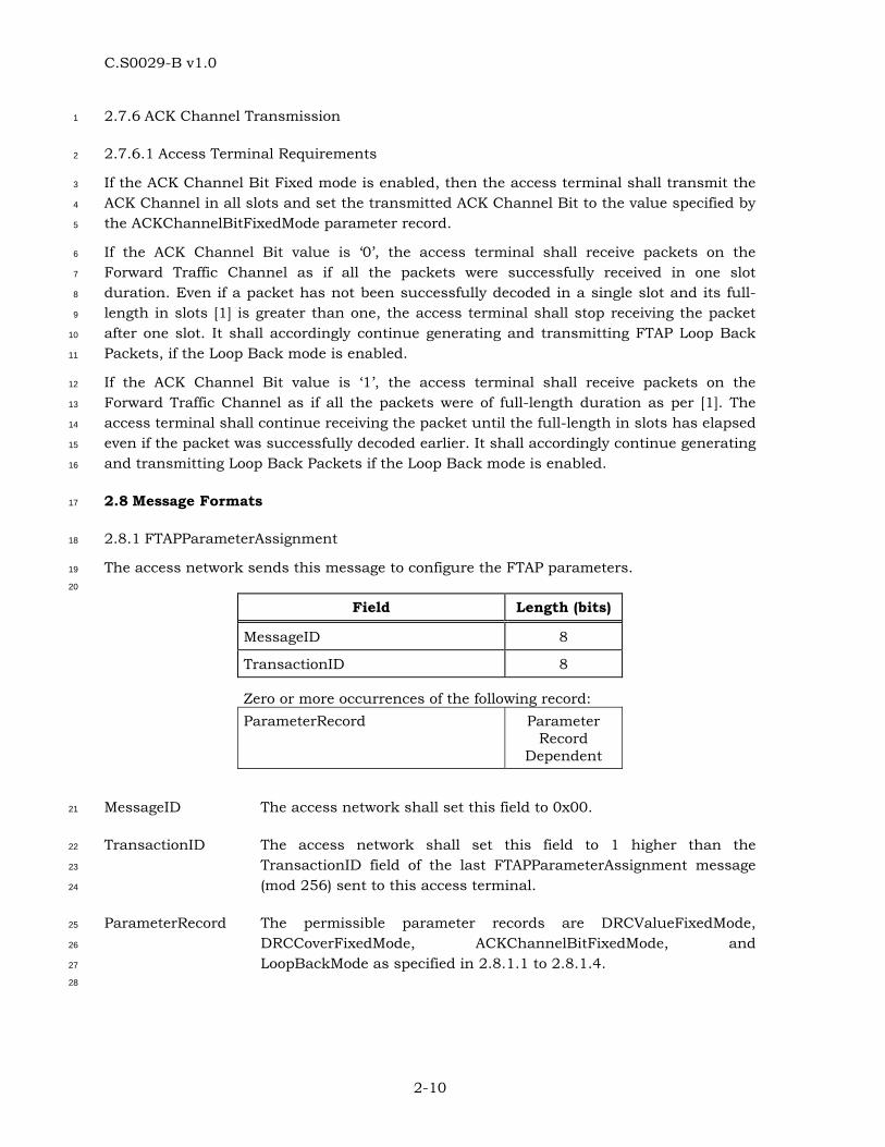
C.S0029-B v1.0
2-10
2.7.6 ACK Channel Transmission 1
2.7.6.1 Access Terminal Requirements 2
If the ACK Channel Bit Fixed mode is enabled, then the access terminal shall transmit the 3
ACK Channel in all slots and set the transmitted ACK Channel Bit to the value specified by 4
the ACKChannelBitFixedMode parameter record. 5
If the ACK Channel Bit value is ‘0’, the access terminal shall receive packets on the 6
Forward Traffic Channel as if all the packets were successfully received in one slot 7
duration. Even if a packet has not been successfully decoded in a single slot and its full-8
length in slots [1] is greater than one, the access terminal shall stop receiving the packet 9
after one slot. It shall accordingly continue generating and transmitting FTAP Loop Back 10
Packets, if the Loop Back mode is enabled. 11
If the ACK Channel Bit value is ‘1’, the access terminal shall receive packets on the 12
Forward Traffic Channel as if all the packets were of full-length duration as per [1]. The 13
access terminal shall continue receiving the packet until the full-length in slots has elapsed 14
even if the packet was successfully decoded earlier. It shall accordingly continue generating 15
and transmitting Loop Back Packets if the Loop Back mode is enabled. 16
2.8 Message Formats 17
2.8.1 FTAPParameterAssignment 18
The access network sends this message to configure the FTAP parameters. 19
20
Field Length (bits)
MessageID 8
TransactionID 8
Zero or more occurrences of the following record: ParameterRecord Parameter
Record Dependent
MessageID The access network shall set this field to 0x00. 21
TransactionID The access network shall set this field to 1 higher than the 22
TransactionID field of the last FTAPParameterAssignment message 23
(mod 256) sent to this access terminal. 24
ParameterRecord The permissible parameter records are DRCValueFixedMode, 25
DRCCoverFixedMode, ACKChannelBitFixedMode, and 26
LoopBackMode as specified in 2.8.1.1 to 2.8.1.4. 27
28
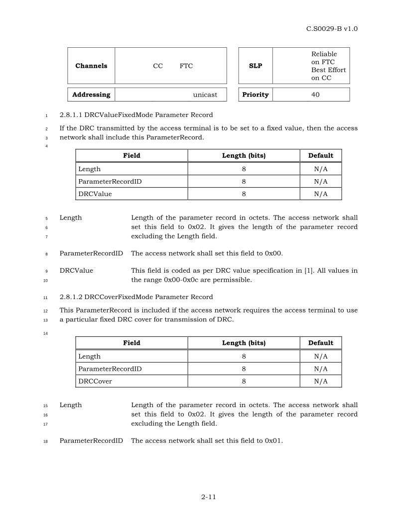
C.S0029-B v1.0
2-11
Channels CC FTC SLP
Reliable on FTC Best Effort on CC
Addressing unicast Priority 40
2.8.1.1 DRCValueFixedMode Parameter Record 1
If the DRC transmitted by the access terminal is to be set to a fixed value, then the access 2
network shall include this ParameterRecord. 3
4
Field Length (bits) Default
Length 8 N/A
ParameterRecordID 8 N/A
DRCValue 8 N/A
Length Length of the parameter record in octets. The access network shall 5
set this field to 0x02. It gives the length of the parameter record 6
excluding the Length field. 7
ParameterRecordID The access network shall set this field to 0x00. 8
DRCValue This field is coded as per DRC value specification in [1]. All values in 9
the range 0x00-0x0c are permissible. 10
2.8.1.2 DRCCoverFixedMode Parameter Record 11
This ParameterRecord is included if the access network requires the access terminal to use 12
a particular fixed DRC cover for transmission of DRC. 13
14
Field Length (bits) Default
Length 8 N/A
ParameterRecordID 8 N/A
DRCCover 8 N/A
Length Length of the parameter record in octets. The access network shall 15
set this field to 0x02. It gives the length of the parameter record 16
excluding the Length field. 17
ParameterRecordID The access network shall set this field to 0x01. 18
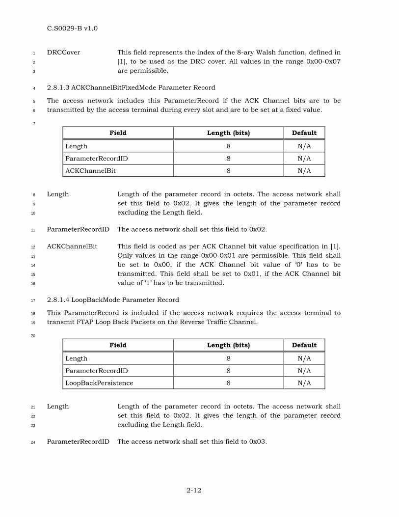
C.S0029-B v1.0
2-12
DRCCover This field represents the index of the 8-ary Walsh function, defined in 1
[1], to be used as the DRC cover. All values in the range 0x00-0x07 2
are permissible. 3
2.8.1.3 ACKChannelBitFixedMode Parameter Record 4
The access network includes this ParameterRecord if the ACK Channel bits are to be 5
transmitted by the access terminal during every slot and are to be set at a fixed value. 6
7
Field Length (bits) Default
Length 8 N/A
ParameterRecordID 8 N/A
ACKChannelBit 8 N/A
Length Length of the parameter record in octets. The access network shall 8
set this field to 0x02. It gives the length of the parameter record 9
excluding the Length field. 10
ParameterRecordID The access network shall set this field to 0x02. 11
ACKChannelBit This field is coded as per ACK Channel bit value specification in [1]. 12
Only values in the range 0x00-0x01 are permissible. This field shall 13
be set to 0x00, if the ACK Channel bit value of ‘0’ has to be 14
transmitted. This field shall be set to 0x01, if the ACK Channel bit 15
value of ‘1’ has to be transmitted. 16
2.8.1.4 LoopBackMode Parameter Record 17
This ParameterRecord is included if the access network requires the access terminal to 18
transmit FTAP Loop Back Packets on the Reverse Traffic Channel. 19
20
Field Length (bits) Default
Length 8 N/A
ParameterRecordID 8 N/A
LoopBackPersistence 8 N/A
Length Length of the parameter record in octets. The access network shall 21
set this field to 0x02. It gives the length of the parameter record 22
excluding the Length field. 23
ParameterRecordID The access network shall set this field to 0x03. 24
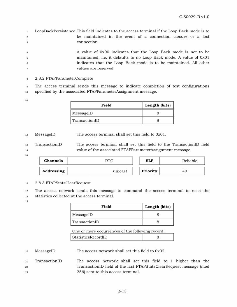
C.S0029-B v1.0
2-13
LoopBackPersistence This field indicates to the access terminal if the Loop Back mode is to 1
be maintained in the event of a connection closure or a lost 2
connection. 3
A value of 0x00 indicates that the Loop Back mode is not to be 4
maintained, i.e. it defaults to no Loop Back mode. A value of 0x01 5
indicates that the Loop Back mode is to be maintained. All other 6
values are reserved. 7
2.8.2 FTAPParameterComplete 8
The access terminal sends this message to indicate completion of test configurations 9
specified by the associated FTAPParameterAssignment message. 10
11
Field Length (bits)
MessageID 8
TransactionID 8
MessageID The access terminal shall set this field to 0x01. 12
TransactionID The access terminal shall set this field to the TransactionID field 13
value of the associated FTAPParameterAssignment message. 14
15
Channels RTC SLP Reliable
Addressing unicast Priority 40
2.8.3 FTAPStatsClearRequest 16
The access network sends this message to command the access terminal to reset the 17
statistics collected at the access terminal. 18
19
Field Length (bits)
MessageID 8
TransactionID 8
One or more occurrences of the following record: StatisticsRecordID 8
MessageID The access network shall set this field to 0x02. 20
TransactionID The access network shall set this field to 1 higher than the 21
TransactionID field of the last FTAPStatsClearRequest message (mod 22
256) sent to this access terminal. 23
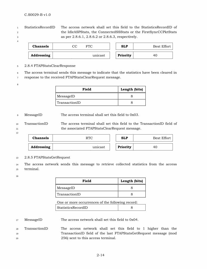
C.S0029-B v1.0
2-14
StatisticsRecordID The access network shall set this field to the StatisticsRecordID of 1
the IdleASPStats, the ConnectedSSStats or the FirstSyncCCPktStats 2
as per 2.8.6.1, 2.8.6.2 or 2.8.6.3, respectively. 3
4
Channels CC FTC SLP Best Effort
Addressing unicast Priority 40
2.8.4 FTAPStatsClearResponse 5
The access terminal sends this message to indicate that the statistics have been cleared in 6
response to the received FTAPStatsClearRequest message. 7
8
Field Length (bits)
MessageID 8
TransactionID 8
MessageID The access terminal shall set this field to 0x03. 9
TransactionID The access terminal shall set this field to the TransactionID field of 10
the associated FTAPStatsClearRequest message. 11
12
Channels RTC SLP Best Effort
Addressing unicast Priority 40
2.8.5 FTAPStatsGetRequest 13
The access network sends this message to retrieve collected statistics from the access 14
terminal. 15
16
Field Length (bits)
MessageID 8
TransactionID 8
One or more occurrences of the following record: StatisticsRecordID 8
MessageID The access network shall set this field to 0x04. 17
TransactionID The access network shall set this field to 1 higher than the 18
TransactionID field of the last FTAPStatsGetRequest message (mod 19
256) sent to this access terminal. 20
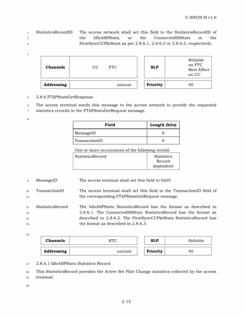
C.S0029-B v1.0
2-15
StatisticsRecordID The access network shall set this field to the StatisticsRecordID of 1
the IdleASPStats, or the ConnectedSSStats or the 2
FirstSyncCCPktStats as per 2.8.6.1, 2.8.6.2 or 2.8.6.3, respectively. 3
4
Channels CC FTC SLP
Reliable on FTC Best Effort on CC
Addressing unicast Priority 40
2.8.6 FTAPStatsGetResponse 5
The access terminal sends this message to the access network to provide the requested 6
statistics records in the FTAPStatsGetRequest message. 7
8
Field Length (bits)
MessageID 8
TransactionID 8
One or more occurrences of the following record: StatisticsRecord Statistics
Record dependent
MessageID The access terminal shall set this field to 0x05. 9
TransactionID The access terminal shall set this field to the TransactionID field of 10
the corresponding FTAPStatsGetRequest message. 11
StatisticsRecord The IdleASPStats StatisticsRecord has the format as described in 12
2.8.6.1. The ConnectedSSStats StatisticsRecord has the format as 13
described in 2.8.6.2. The FirstSyncCCPktStats StatisticsRecord has 14
the format as described in 2.8.6.3. 15
16
Channels RTC SLP Reliable
Addressing unicast Priority 40
2.8.6.1 IdleASPStats Statistics Record 17
This StatisticsRecord provides the Active Set Pilot Change statistics collected by the access 18
terminal. 19
20
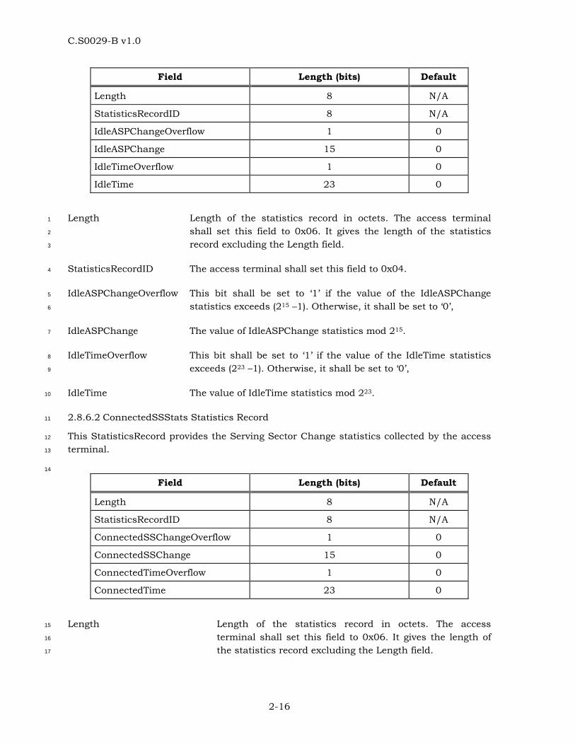
C.S0029-B v1.0
2-16
Field Length (bits) Default
Length 8 N/A
StatisticsRecordID 8 N/A
IdleASPChangeOverflow 1 0
IdleASPChange 15 0
IdleTimeOverflow 1 0
IdleTime 23 0
Length Length of the statistics record in octets. The access terminal 1
shall set this field to 0x06. It gives the length of the statistics 2
record excluding the Length field. 3
StatisticsRecordID The access terminal shall set this field to 0x04. 4
IdleASPChangeOverflow This bit shall be set to ‘1’ if the value of the IdleASPChange 5
statistics exceeds (215 –1). Otherwise, it shall be set to ‘0’, 6
IdleASPChange The value of IdleASPChange statistics mod 215. 7
IdleTimeOverflow This bit shall be set to ‘1’ if the value of the IdleTime statistics 8
exceeds (223 –1). Otherwise, it shall be set to ‘0’, 9
IdleTime The value of IdleTime statistics mod 223. 10
2.8.6.2 ConnectedSSStats Statistics Record 11
This StatisticsRecord provides the Serving Sector Change statistics collected by the access 12
terminal. 13
14
Field Length (bits) Default
Length 8 N/A
StatisticsRecordID 8 N/A
ConnectedSSChangeOverflow 1 0
ConnectedSSChange 15 0
ConnectedTimeOverflow 1 0
ConnectedTime 23 0
Length Length of the statistics record in octets. The access 15
terminal shall set this field to 0x06. It gives the length of 16
the statistics record excluding the Length field. 17
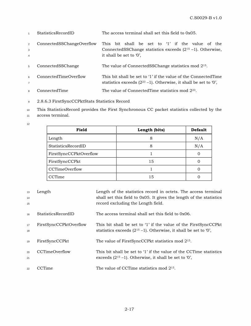
C.S0029-B v1.0
2-17
StatisticsRecordID The access terminal shall set this field to 0x05. 1
ConnectedSSChangeOverflow This bit shall be set to ‘1’ if the value of the 2
ConnectedSSChange statistics exceeds (215 –1). Otherwise, 3
it shall be set to ‘0’, 4
ConnectedSSChange The value of ConnectedSSChange statistics mod 215. 5
ConnectedTimeOverflow This bit shall be set to ‘1’ if the value of the ConnectedTime 6
statistics exceeds (223 –1). Otherwise, it shall be set to ‘0’, 7
ConnectedTime The value of ConnectedTime statistics mod 223. 8
2.8.6.3 FirstSyncCCPktStats Statistics Record 9
This StatisticsRecord provides the First Synchronous CC packet statistics collected by the 10
access terminal. 11
12
Field Length (bits) Default
Length 8 N/A
StatisticsRecordID 8 N/A
FirstSyncCCPktOverflow 1 0
FirstSyncCCPkt 15 0
CCTimeOverflow 1 0
CCTime 15 0
Length Length of the statistics record in octets. The access terminal 13
shall set this field to 0x05. It gives the length of the statistics 14
record excluding the Length field. 15
StatisticsRecordID The access terminal shall set this field to 0x06. 16
FirstSyncCCPktOverflow This bit shall be set to ‘1’ if the value of the FirstSyncCCPkt 17
statistics exceeds (215 –1). Otherwise, it shall be set to ‘0’, 18
FirstSyncCCPkt The value of FirstSyncCCPkt statistics mod 215. 19
CCTimeOverflow This bit shall be set to ‘1’ if the value of the CCTime statistics 20
exceeds (215 –1). Otherwise, it shall be set to ‘0’, 21
CCTime The value of CCTime statistics mod 215. 22
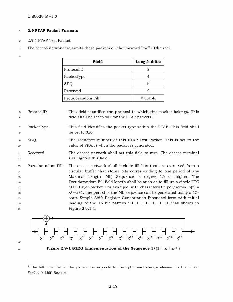
C.S0029-B v1.0
2-18
2.9 FTAP Packet Formats 1
2.9.1 FTAP Test Packet 2
The access network transmits these packets on the Forward Traffic Channel. 3
4
Field Length (bits)
ProtocolID 2
PacketType 4
SEQ 14
Reserved 2
Pseudorandom Fill Variable
ProtocolID This field identifies the protocol to which this packet belongs. This 5
field shall be set to ‘00’ for the FTAP packets. 6
PacketType This field identifies the packet type within the FTAP. This field shall 7
be set to 0x0. 8
SEQ The sequence number of this FTAP Test Packet. This is set to the 9
value of V(STest) when the packet is generated. 10
Reserved The access network shall set this field to zero. The access terminal 11
shall ignore this field. 12
Pseudorandom Fill The access network shall include fill bits that are extracted from a 13
circular buffer that stores bits corresponding to one period of any 14
Maximal Length (ML) Sequence of degree 15 or higher. The 15
Pseudorandom Fill field length shall be such as to fill up a single FTC 16
MAC Layer packet. For example, with characteristic polynomial p(x) = 17
x15+x+1, one period of the ML sequence can be generated using a 15-18
state Simple Shift Register Generator in Fibonacci form with initial 19
loading of the 15 bit pattern ‘1111 1111 1111 111’2as shown in 20
Figure 2.9.1-1. 21
+
x x2 x3 x4 x5 x6 x7 x8 x9 x10 x11 x12 x13 x14 x15 22
Figure 2.9-1 SSRG Implementation of the Sequence 1/(1 + x + x15 ) 23
2 The left most bit in the pattern corresponds to the right most storage element in the Linear Feedback Shift Register
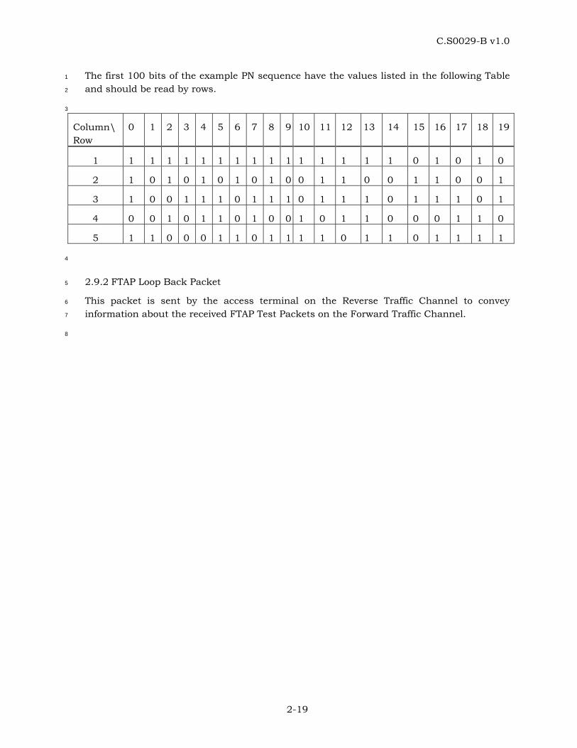
C.S0029-B v1.0
2-19
The first 100 bits of the example PN sequence have the values listed in the following Table 1
and should be read by rows. 2
3
Column\ Row
0 1 2 3 4 5 6 7 8 9 10 11 12 13 14 15 16 17 18 19
1 1 1 1 1 1 1 1 1 1 1 1 1 1 1 1 0 1 0 1 0
2 1 0 1 0 1 0 1 0 1 0 0 1 1 0 0 1 1 0 0 1
3 1 0 0 1 1 1 0 1 1 1 0 1 1 1 0 1 1 1 0 1
4 0 0 1 0 1 1 0 1 0 0 1 0 1 1 0 0 0 1 1 0
5 1 1 0 0 0 1 1 0 1 1 1 1 0 1 1 0 1 1 1 1
4
2.9.2 FTAP Loop Back Packet 5
This packet is sent by the access terminal on the Reverse Traffic Channel to convey 6
information about the received FTAP Test Packets on the Forward Traffic Channel. 7
8
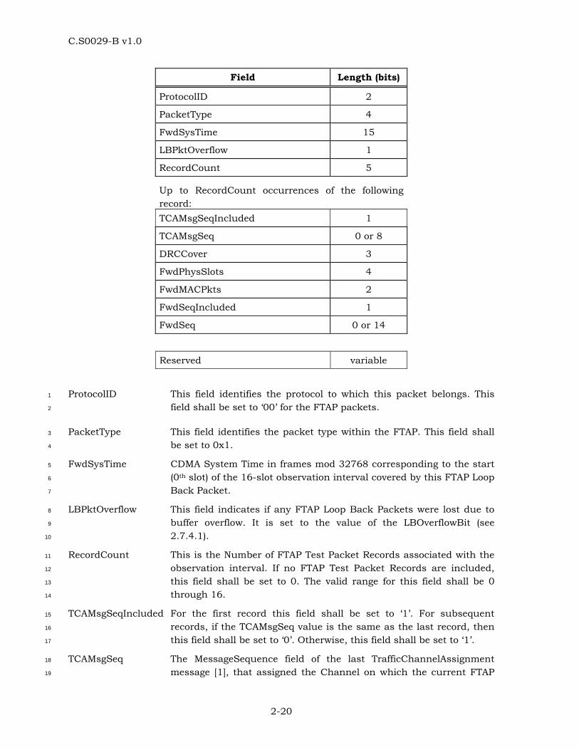
C.S0029-B v1.0
2-20
Field Length (bits)
ProtocolID 2
PacketType 4
FwdSysTime 15
LBPktOverflow 1
RecordCount 5
Up to RecordCount occurrences of the following record: TCAMsgSeqIncluded 1
TCAMsgSeq 0 or 8
DRCCover 3
FwdPhysSlots 4
FwdMACPkts 2
FwdSeqIncluded 1
FwdSeq 0 or 14
Reserved variable
ProtocolID This field identifies the protocol to which this packet belongs. This 1
field shall be set to ‘00’ for the FTAP packets. 2
PacketType This field identifies the packet type within the FTAP. This field shall 3
be set to 0x1. 4
FwdSysTime CDMA System Time in frames mod 32768 corresponding to the start 5
(0th slot) of the 16-slot observation interval covered by this FTAP Loop 6
Back Packet. 7
LBPktOverflow This field indicates if any FTAP Loop Back Packets were lost due to 8
buffer overflow. It is set to the value of the LBOverflowBit (see 9
2.7.4.1). 10
RecordCount This is the Number of FTAP Test Packet Records associated with the 11
observation interval. If no FTAP Test Packet Records are included, 12
this field shall be set to 0. The valid range for this field shall be 0 13
through 16. 14
TCAMsgSeqIncluded For the first record this field shall be set to ‘1’. For subsequent 15
records, if the TCAMsgSeq value is the same as the last record, then 16
this field shall be set to ‘0’. Otherwise, this field shall be set to ‘1’. 17
TCAMsgSeq The MessageSequence field of the last TrafficChannelAssignment 18
message [1], that assigned the Channel on which the current FTAP 19
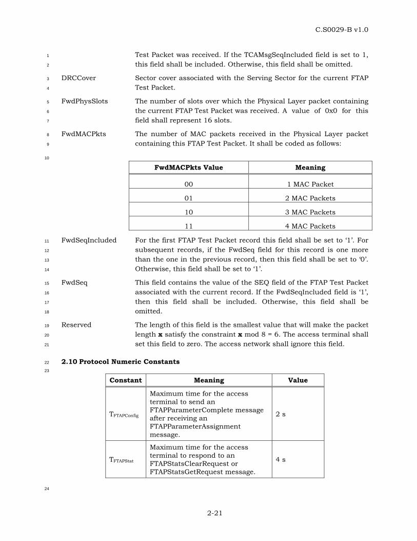
C.S0029-B v1.0
2-21
Test Packet was received. If the TCAMsgSeqIncluded field is set to 1, 1
this field shall be included. Otherwise, this field shall be omitted. 2
DRCCover Sector cover associated with the Serving Sector for the current FTAP 3
Test Packet. 4
FwdPhysSlots The number of slots over which the Physical Layer packet containing 5
the current FTAP Test Packet was received. A value of 0x0 for this 6
field shall represent 16 slots. 7
FwdMACPkts The number of MAC packets received in the Physical Layer packet 8
containing this FTAP Test Packet. It shall be coded as follows: 9
10
FwdMACPkts Value Meaning
00 1 MAC Packet
01 2 MAC Packets
10 3 MAC Packets
11 4 MAC Packets
FwdSeqIncluded For the first FTAP Test Packet record this field shall be set to ‘1’. For 11
subsequent records, if the FwdSeq field for this record is one more 12
than the one in the previous record, then this field shall be set to ‘0’. 13
Otherwise, this field shall be set to ‘1’. 14
FwdSeq This field contains the value of the SEQ field of the FTAP Test Packet 15
associated with the current record. If the FwdSeqIncluded field is ‘1’, 16
then this field shall be included. Otherwise, this field shall be 17
omitted. 18
Reserved The length of this field is the smallest value that will make the packet 19
length x satisfy the constraint x mod 8 = 6. The access terminal shall 20
set this field to zero. The access network shall ignore this field. 21
2.10 Protocol Numeric Constants 22
23
Constant Meaning Value
TFTAPConfig
Maximum time for the access terminal to send an FTAPParameterComplete message after receiving an FTAPParameterAssignment message.
2 s
TFTAPStat
Maximum time for the access terminal to respond to an FTAPStatsClearRequest or FTAPStatsGetRequest message.
4 s
24
C.S0029-B v1.0
2-22
2.11 Interface to Other Protocols 1
2.11.1 Commands 2
This protocol does not issue any commands. 3
2.11.2 Indications 4
This protocol registers to receive the following indications: 5
• ConnectedState.ConnectionClosed 6
• RouteUpdate.IdleHO 7
• IdleState.ConnectionOpened 8

C.S0029-B v1.0
2-23
No text. 1

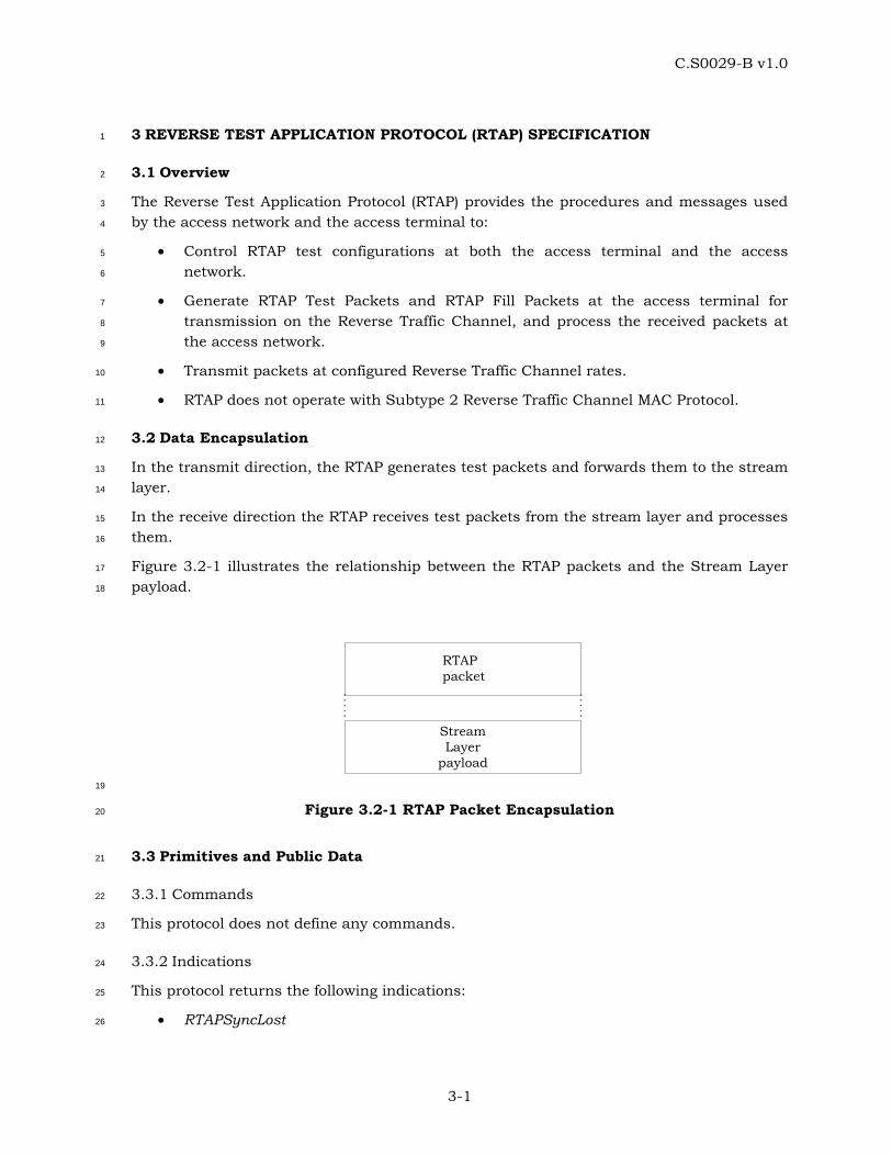
C.S0029-B v1.0
3-1
3 REVERSE TEST APPLICATION PROTOCOL (RTAP) SPECIFICATION 1
3.1 Overview 2
The Reverse Test Application Protocol (RTAP) provides the procedures and messages used 3
by the access network and the access terminal to: 4
• Control RTAP test configurations at both the access terminal and the access 5
network. 6
• Generate RTAP Test Packets and RTAP Fill Packets at the access terminal for 7
transmission on the Reverse Traffic Channel, and process the received packets at 8
the access network. 9
• Transmit packets at configured Reverse Traffic Channel rates. 10
• RTAP does not operate with Subtype 2 Reverse Traffic Channel MAC Protocol. 11
3.2 Data Encapsulation 12
In the transmit direction, the RTAP generates test packets and forwards them to the stream 13
layer. 14
In the receive direction the RTAP receives test packets from the stream layer and processes 15
them. 16
Figure 3.2-1 illustrates the relationship between the RTAP packets and the Stream Layer 17
payload. 18
StreamLayer
payload
RTAPpacket
19
Figure 3.2-1 RTAP Packet Encapsulation 20
3.3 Primitives and Public Data 21
3.3.1 Commands 22
This protocol does not define any commands. 23
3.3.2 Indications 24
This protocol returns the following indications: 25
• RTAPSyncLost 26
C.S0029-B v1.0
3-2
3.3.3 Public Data 1
Subtype for this application. 2
3.4 Basic Protocol Numbers 3
RTAP is a protocol associated with the Test Application. This protocol shall use the 4
application subtype value for the Test Application as specified in 1.5. 5
3.5 Protocol Data Unit 6
The transmission unit of this protocol is an RTAP packet. The RTAP packet size is 7
determined by the lower layers that are negotiated during session configuration. 8
The RTAP also uses signaling messages for controlling and configuring the access terminal 9
and the access network. When RTAP sends these messages it shall use the Signaling 10
Application [1]. 11
3.6 Test Statistics 12
3.6.1 Access Network Requirements 13
The access network may maintain the following statistics: 14
• RTCMACPktSent[i]: Array whose (i+1)th element contains the number of RTC MAC 15
Packets that were sent by the access terminal at a rate corresponding to the 16
RateIndex i, as per Table 3.8.1.2-1. 17
• RTCMACPktRecd[i]: Array whose (i+1)th element contains the number of RTC MAC 18
Packets that were received by the access network at a rate corresponding to the 19
RateIndex i, as per Table 3.8.1.2-1. 20
• RTAPTestTime: The duration of the RTAP test in frames. 21
3.7 Procedures 22
The RTAP is specified by the following procedures, which control and configure different 23
aspects of the Reverse Traffic Channel tests. 24
• Test Parameter Configuration: Procedures and messages for configuring test 25
parameters. 26
• RTAP Packet Transmission and Reception: Procedures for sending and receiving 27
RTAP Test Packets and RTAP Fill Packets on the Reverse Traffic Channel. 28
3.7.1 Test Parameter Configuration 29
3.7.1.1 Access Terminal Requirements 30
When the protocol is instantiated, the access terminal shall execute the configuration 31
initialization procedure in 3.7.1.1.1. 32
When the protocol receives a ConnectedState.ConnectionClosed [1] indication, the access 33
terminal shall execute the configuration initialization procedure in 3.7.1.1.2. 34

C.S0029-B v1.0
3-3
If the access terminal receives an RTAPParameterAssignment message, it shall do the 1
following steps in sequence: 2
• Execute the configuration initialization procedure in 3.7.1.1.1. 3
• Execute the test parameter initialization procedure in 3.7.1.1.3. 4
• If the message includes the RTAPTestPktEnable parameter record, then the RTAP 5
Test Packet mode is enabled, and the value of the RTAPTestPktPersistence field is 6
stored. The RTAP Test Packet buffer is cleared and the RTAPTestPktOverflowBit is 7
set to ‘0’ (see 3.7.2.1.1). 8
• If the message includes the PacketRateMode parameter record, then the Configured 9
Packet Rate mode is enabled. The values of the MinRateIndex and MaxRateIndex 10
fields are stored (see 3.7.2.1.2). 11
• Send an RTAPParameterComplete message. The TransactionID field shall be set to 12
the same value as that received in the RTAPParameterAssignment message. The 13
RTAPParameterComplete message shall be sent within TRTAPConfig from when the 14
RTAPParameterAssignment message is received. 15
3.7.1.1.1 Access Terminal Configuration Initialization 16
When the protocol is instantiated or an RTAPParameterAssignment message is received, 17
the access terminal shall initialize the test configuration as follows: 18
• The RTAP Test Packet mode is disabled. 19
• The Configured Packet Rate mode is disabled. 20
3.7.1.1.2 Access Terminal Configuration for Closed or Lost Connection 21
When the protocol receives a ConnectedState.ConnectionClosed indication [1], the access 22
terminal shall initialize the test configuration as follows: 23
• If the RTAP Test Packet mode is enabled, and the value of the 24
RTAPTestPktPersistence field of the RTAPTestPktEnable parameter record in the 25
last received RTAPParameterAssignment message is ‘00’, then the RTAP Test Packet 26
mode is disabled. 27
• The Configured Packet Rate mode is disabled. 28
3.7.1.1.3 Access Terminal Test Parameter Initialization 29
The access terminal shall set Vi(SRev), the 12-bit sequence number associated with RTC 30
MAC Packets transmitted at the rate corresponding to RateIndex i (Table 3.8.1.2-1), to zero, 31
for all possible RTC rates [1]. 32
3.7.1.2 Access Network Requirements 33
To change the test configuration the access network shall perform the following steps: 34
C.S0029-B v1.0
3-4
• Send an RTAPParameterAssignment message to the access terminal and wait for an 1
RTAPParameterComplete message containing the same TransactionID as that in the 2
RTAPParameterAssignment message. 3
• When the expected RTAPParameterComplete message is received, execute the Test 4
Statistics Initialization procedure in 3.7.1.2.1. 5
3.7.1.2.1 Access Network Test Statistics Initialization 6
The access network shall set the test statistics as follows: 7
• RTCMACPktSent[i] to zero for all possible i. 8
• RTCMACPktRecd[i] to zero for all possible i. 9
• RTAPTestTime to zero. 10
3.7.2 RTAP Packet Transmission and Reception 11
3.7.2.1 Access Terminal Requirements 12
3.7.2.1.1 Generation and Transmission 13
If the RTAP Test Packet mode is enabled, the access terminal shall generate an RTAP Test 14
Packet at the beginning of every 16-slot interval aligned to the CDMA System Time [1] in 15
frames. 16
The access terminal shall obey the following rules: 17
• The RTAP Packets shall be generated only in the Connected State of the Air Link 18
Management Protocol. 19
• The information contained in the RTAP Test Packet (see 3.9.1) shall cover RTC MAC 20
Packets transmitted up to, but not including, the time instant of generation. 21
• The access terminal shall assign a transmission priority of 55 to RTAP Test Packets. 22
• The transmission rate for the RTC MAC Packet shall be determined as specified in 23
3.7.2.1.2. 24
• The access terminal shall queue the generated RTAP Test Packets. The access 25
terminal shall provide buffering for at least 16 RTAP Test Packets. The 26
RTAPTestPktOverflowBit indicates if any RTAP Test Packets have been lost due to 27
lack of buffer space. When a packet is lost due to lack of buffer space, the 28
RTAPTestPktOverflowBit shall be set to ‘1’. 29
The access terminal shall follow the following rules for transmitting an RTAP Test Packet: 30
• The access terminal shall transmit the queued RTAP Test Packets in the Connected 31
State of the Air Link Management Protocol [1]. 32
• If the Configured Packet Rate mode is enabled, the access terminal shall transmit 33
an RTAP Fill Packet of the size necessary for the RTC MAC Packet containing the 34
RTAP Test Packet at the selected rate. The access terminal shall set the priority of 35
the RTAP Fill Packet to 255. 36
C.S0029-B v1.0
3-5
• When the access terminal transmits an RTC MAC Packet at a rate with RateIndex i 1
(Table 3.8.1.2-1), it shall increment the sequence number Vi(SRev). 2
• If multiple RTAP Test Packets are included in an RTC MAC Packet, the RTAP Test 3
Packets shall be ordered so that a packet corresponding to an earlier time appears 4
first. 5
• If the access terminal receives a ConnectedState.ConnectionClosed [1] indication, 6
and it has queued RTAP Test packets, it shall not attempt to establish a connection 7
to transmit the packets. 8
3.7.2.1.2 Rate Selection 9
If the Configured Packet Rate mode is enabled, the access terminal shall obey the following 10
rules to select a Reverse Traffic Channel rate; otherwise, the access terminal shall select a 11
rate as per the Reverse Traffic Channel MAC Protocol [1]. 12
The access terminal shall maintain the following variables: 13
• MinRate: Value of the MinRateIndex field received in the PacketRateMode parameter 14
record of the RTAPParameterAssignment message. 15
• MaxRate: Value of the MaxRateIndex field received in the PacketRateMode 16
parameter record of the RTAPParameterAssignment message. 17
• MACMaxRate: RateIndex as per Table 3.8.1.2-1 corresponding to the maximum rate 18
allowed by the Reverse Traffic Channel MAC protocol [1]. 19
• TargetRate: RateIndex corresponding to the desired rate. 20
• SelectedRate: RateIndex corresponding to the selected rate. 21
For the first RTC MAC Packet following the start of the test, the access terminal shall set 22
TargetRate to MinRate, and the SelectedRate = Min (TargetRate,MACMaxRate). For all the 23
subsequent RTC MAC Packets, the access terminal shall choose the rate as follows: 24
TargetRate = TargetRate + 1; 25
If (TargetRate > MaxRate) 26
TargetRate = MinRate; 27
SelectedRate = Min (TargetRate, MACMaxRate); 28
3.7.2.2 Access Network Requirements 29
The access network shall maintain the following variables: 30
• V(RRTAP): A 15-bit variable that corresponds to the sequence number of the next 31
expected RTAP Test Packet. 32
• X[i]: A 12-bit variable that represents the sequence number corresponding to the 33
next expected RTC MAC Packet transmitted at a rate associated with RateIndex i as 34
per Table 3.8.1.2-1. 35
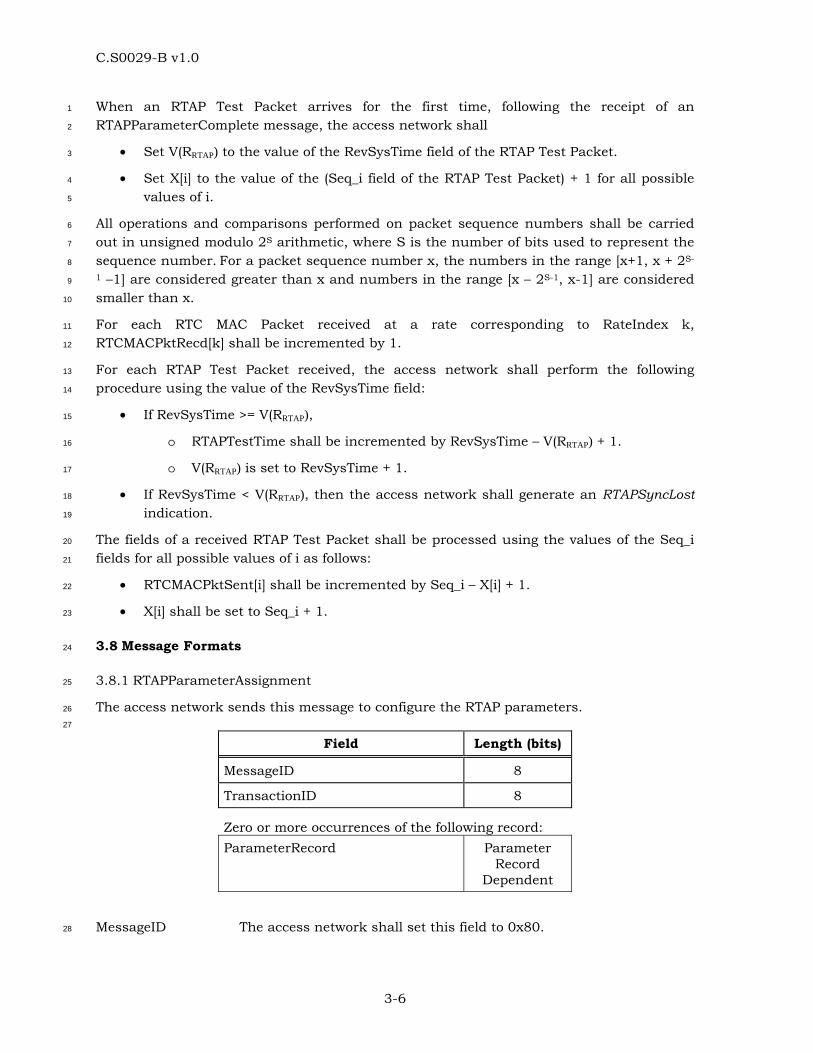
C.S0029-B v1.0
3-6
When an RTAP Test Packet arrives for the first time, following the receipt of an 1
RTAPParameterComplete message, the access network shall 2
• Set V(RRTAP) to the value of the RevSysTime field of the RTAP Test Packet. 3
• Set X[i] to the value of the (Seq_i field of the RTAP Test Packet) + 1 for all possible 4
values of i. 5
All operations and comparisons performed on packet sequence numbers shall be carried 6
out in unsigned modulo 2S arithmetic, where S is the number of bits used to represent the 7
sequence number. For a packet sequence number x, the numbers in the range [x+1, x + 2S-8
1 –1] are considered greater than x and numbers in the range [x – 2S-1, x-1] are considered 9
smaller than x. 10
For each RTC MAC Packet received at a rate corresponding to RateIndex k, 11
RTCMACPktRecd[k] shall be incremented by 1. 12
For each RTAP Test Packet received, the access network shall perform the following 13
procedure using the value of the RevSysTime field: 14
• If RevSysTime >= V(RRTAP), 15
o RTAPTestTime shall be incremented by RevSysTime – V(RRTAP) + 1. 16
o V(RRTAP) is set to RevSysTime + 1. 17
• If RevSysTime < V(RRTAP), then the access network shall generate an RTAPSyncLost 18
indication. 19
The fields of a received RTAP Test Packet shall be processed using the values of the Seq_i 20
fields for all possible values of i as follows: 21
• RTCMACPktSent[i] shall be incremented by Seq_i – X[i] + 1. 22
• X[i] shall be set to Seq_i + 1. 23
3.8 Message Formats 24
3.8.1 RTAPParameterAssignment 25
The access network sends this message to configure the RTAP parameters. 26
27
Field Length (bits)
MessageID 8
TransactionID 8
Zero or more occurrences of the following record: ParameterRecord Parameter
Record Dependent
MessageID The access network shall set this field to 0x80. 28

C.S0029-B v1.0
3-7
TransactionID The access network shall set this field to 1 higher than the 1
TransactionID field of the last RTAPParameterAssignment message 2
(mod 256) sent to this access terminal. 3
ParameterRecord The permissible parameter records are RTAPTestPktEnable, and 4
PacketRateMode as specified in 3.8.1.1 to 3.8.1.2. 5
6
Channels CC FTC SLP
Reliable on FTC Best Effort on CC
Addressing unicast Priority 40
3.8.1.1 RTAPTestPktEnable Parameter Record 7
If the access terminal is to start sending RTAP Test Packets on the Reverse Traffic Channel, 8
then the access network includes this ParameterRecord. 9
10
Field Length (bits) Default
Length 8 N/A
ParameterRecordID 8 N/A
RTAPTestPktPersistence 8 N/A
Length Length of the parameter record in octets. The access network shall 11
set this field to 0x02. It gives the length of the parameter record 12
excluding the Length field. 13
ParameterRecordID The access network shall set this field to 0x00. 14
RTAPTestPktPersistence 15
This field indicates to the access terminal if the RTAP Test Packet 16
Enable mode is to be maintained in the event of a connection closure 17
or a lost connection. 18
A value of 0x00 indicates that the RTAP Test Packet Enable mode is 19
not to be maintained. A value of 0x01 indicates that the RTAP Test 20
Packet Enable mode is to be maintained. All other values are 21
reserved. 22
3.8.1.2 PacketRateMode Parameter Record 23
The access network includes this ParameterRecord if the Reverse Traffic Channel rate is to 24
be configured. 25
26
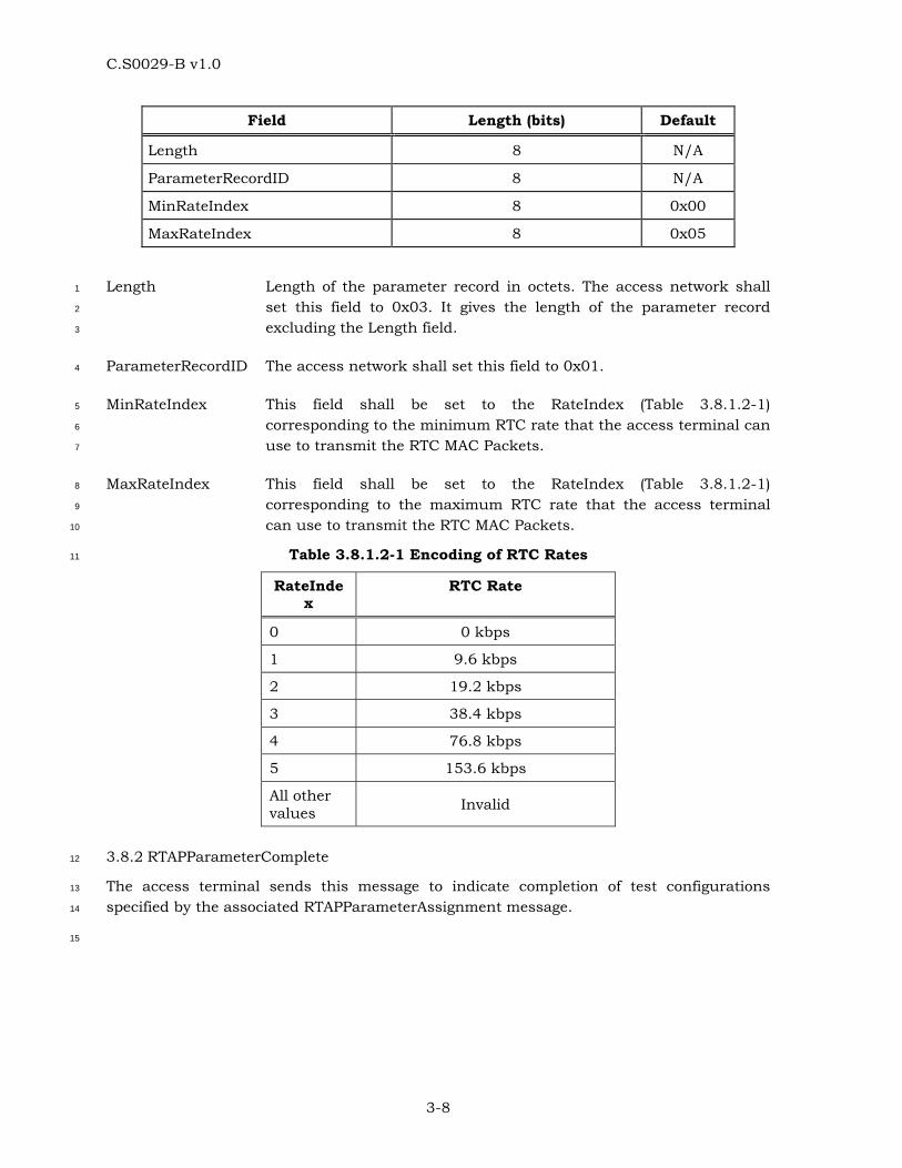
C.S0029-B v1.0
3-8
Field Length (bits) Default
Length 8 N/A
ParameterRecordID 8 N/A
MinRateIndex 8 0x00
MaxRateIndex 8 0x05
Length Length of the parameter record in octets. The access network shall 1
set this field to 0x03. It gives the length of the parameter record 2
excluding the Length field. 3
ParameterRecordID The access network shall set this field to 0x01. 4
MinRateIndex This field shall be set to the RateIndex (Table 3.8.1.2-1) 5
corresponding to the minimum RTC rate that the access terminal can 6
use to transmit the RTC MAC Packets. 7
MaxRateIndex This field shall be set to the RateIndex (Table 3.8.1.2-1) 8
corresponding to the maximum RTC rate that the access terminal 9
can use to transmit the RTC MAC Packets. 10
Table 3.8.1.2-1 Encoding of RTC Rates 11
RateIndex
RTC Rate
0 0 kbps
1 9.6 kbps
2 19.2 kbps
3 38.4 kbps
4 76.8 kbps
5 153.6 kbps
All other values Invalid
3.8.2 RTAPParameterComplete 12
The access terminal sends this message to indicate completion of test configurations 13
specified by the associated RTAPParameterAssignment message. 14
15
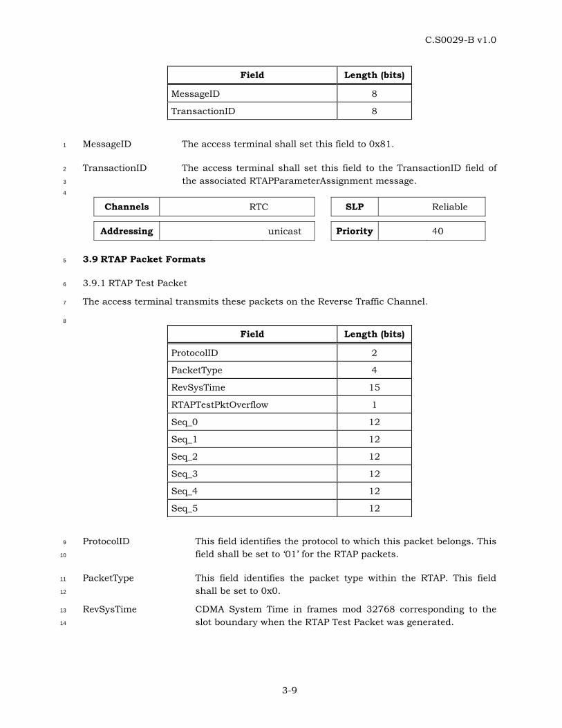
C.S0029-B v1.0
3-9
Field Length (bits)
MessageID 8
TransactionID 8
MessageID The access terminal shall set this field to 0x81. 1
TransactionID The access terminal shall set this field to the TransactionID field of 2
the associated RTAPParameterAssignment message. 3
4
Channels RTC SLP Reliable
Addressing unicast Priority 40
3.9 RTAP Packet Formats 5
3.9.1 RTAP Test Packet 6
The access terminal transmits these packets on the Reverse Traffic Channel. 7
8
Field Length (bits)
ProtocolID 2
PacketType 4
RevSysTime 15
RTAPTestPktOverflow 1
Seq_0 12
Seq_1 12
Seq_2 12
Seq_3 12
Seq_4 12
Seq_5 12
ProtocolID This field identifies the protocol to which this packet belongs. This 9
field shall be set to ‘01’ for the RTAP packets. 10
PacketType This field identifies the packet type within the RTAP. This field 11
shall be set to 0x0. 12
RevSysTime CDMA System Time in frames mod 32768 corresponding to the 13
slot boundary when the RTAP Test Packet was generated. 14

C.S0029-B v1.0
3-10
RTAPTestPktOverflow This field indicates if any RTAP Test Packets were lost due to 1
buffer overflow. It is set to the value of the 2
RTAPTestPktOverflowBit (see 3.7.2.1.1). 3
Seq_0 This is the sequence number V0(SREV) (see 3.7.1.1.3) prior to the 4
generation of this RTAP Test Packet. 5
Seq_1 This is the sequence number V1(SREV) (see 3.7.1.1.3) prior to the 6
generation of this RTAP Test Packet. 7
Seq_2 This is the sequence number V2(SREV) (see 3.7.1.1.3) prior to the 8
generation of this RTAP Test Packet. 9
Seq_3 This is the sequence number V3(SREV) (see 3.7.1.1.3) prior to the 10
generation of this RTAP Test Packet. 11
Seq_4 This is the sequence number V4(SREV) (see 3.7.1.1.3) prior to the 12
generation of this RTAP Test Packet. 13
Seq_5 This is the sequence number V5(SREV) (see 3.7.1.1.3) prior to the 14
generation of this RTAP Test Packet. 15
3.9.2 RTAP Fill Packet 16
This is a variable length packet used to fill an RTC MAC Packet for transmission at a 17
configured rate. 18
19
Field Length (bits)
ProtocolID 2
PacketType 4
DataFill Variable
ProtocolID This field identifies the protocol to which this packet belongs. This 20
field shall be set to ‘01’ for the RTAP packets. 21
PacketType This field identifies the packet type within the RTAP. This field shall 22
be set to 0x1. 23
DataFill The access terminal shall set this variable length field to zero. The 24
access network shall ignore this field. 25
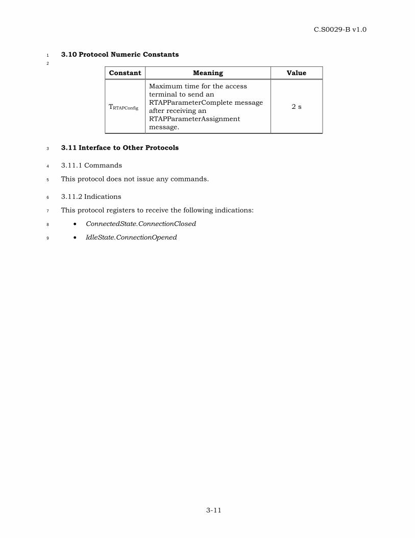
C.S0029-B v1.0
3-11
3.10 Protocol Numeric Constants 1
2
Constant Meaning Value
TRTAPConfig
Maximum time for the access terminal to send an RTAPParameterComplete message after receiving an RTAPParameterAssignment message.
2 s
3.11 Interface to Other Protocols 3
3.11.1 Commands 4
This protocol does not issue any commands. 5
3.11.2 Indications 6
This protocol registers to receive the following indications: 7
• ConnectedState.ConnectionClosed 8
• IdleState.ConnectionOpened 9

C.S0029-B v1.0
3-12
No text. 1
C.S0029-B v1.0
4-1
4 FORWARD ENHANCED TEST APPLICATION PROTOCOL (FETAP) SPECIFICATION 1
4.1 Overview 2
The Forward Enhanced Test Application Protocol (FETAP) provides the procedures and 3
messages used by the access terminal and the access network to: 4
• Control FETAP test configurations at both the access terminal and the access 5
network. 6
• Generate PL_0_1_2 FETAP Test Packets at the access network for transmission on 7
the Forward Traffic Channel and process the received packets at the access 8
terminal. 9
• Generate and transmit information about the received PL_0_1_2 FETAP Test 10
Packets at the access terminal through PL_0_1 FETAP Loop Back Packets and PL_2 11
FETAP Loop Back Packets. 12
• Transmit configured ACK Channel bits, DRC values and DRC covers. 13
• Transmit ACK Channel using configured modulation type. Valid only for Subtype 2 14
Physical Layer Protocol [1]. 15
• Collect statistics on the changes in the serving sector as seen at the access terminal 16
in the Idle State and the Connected State. 17
• Collect statistics on the number of successfully received first Synchronous Control 18
Channel packets. 19
Throughout this section, the notation ‘PL_0_1_2’ refers to Subtype 0, 1, or 2 Physical Layer 20
Protocol [1] applicability. The notation ‘PL_0_1’ refers to Subtype 0 or 1 Physical Layer 21
Protocol [1] applicability. The notation ‘PL_2’ refers to Subtype 2 Physical Layer Protocol [1] 22
applicability. 23
4.2 Data Encapsulation 24
In the transmit direction, the FETAP generates test packets and forwards them to the 25
stream layer. 26
In the receive direction the FETAP receives test packets from the stream layer and 27
processes them. 28
Figure 4.2-1 illustrates the relationship between the FETAP packets and the Stream Layer 29
payload. 30
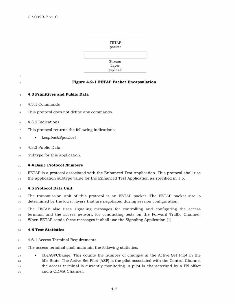
C.S0029-B v1.0
4-2
StreamLayer
payload
FETAPpacket
1
Figure 4.2-1 FETAP Packet Encapsulation 2
4.3 Primitives and Public Data 3
4.3.1 Commands 4
This protocol does not define any commands. 5
4.3.2 Indications 6
This protocol returns the following indications: 7
• LoopbackSyncLost 8
4.3.3 Public Data 9
Subtype for this application. 10
4.4 Basic Protocol Numbers 11
FETAP is a protocol associated with the Enhanced Test Application. This protocol shall use 12
the application subtype value for the Enhanced Test Application as specified in 1.5. 13
4.5 Protocol Data Unit 14
The transmission unit of this protocol is an FETAP packet. The FETAP packet size is 15
determined by the lower layers that are negotiated during session configuration. 16
The FETAP also uses signaling messages for controlling and configuring the access 17
terminal and the access network for conducting tests on the Forward Traffic Channel. 18
When FETAP sends these messages it shall use the Signaling Application [1]. 19
4.6 Test Statistics 20
4.6.1 Access Terminal Requirements 21
The access terminal shall maintain the following statistics: 22
• IdleASPChange: This counts the number of changes in the Active Set Pilot in the 23
Idle State. The Active Set Pilot (ASP) is the pilot associated with the Control Channel 24
the access terminal is currently monitoring. A pilot is characterized by a PN offset 25
and a CDMA Channel. 26
C.S0029-B v1.0
4-3
• IdleTime: Elapsed time in slots in the Idle State since the start of statistics 1
collection. 2
• ConnectedSSChange: This counts the number of changes in the Serving Sector (SS) 3
in the connected State. The serving sector is the one the DRC is pointed at. When 4
the DRC is re-pointed from one sector to another, the DRC cover transitions 5
through a NULL cover. For example, if the DRC cover changes from a sector cover A 6
through NULL cover to a sector cover B (with A not equal to B), it is counted as one 7
SS change. On the other hand, if DRC cover changes from a sector cover A through 8
NULL cover to a sector cover A again, it is not counted as an SS change. 9
• ConnectedTime: Elapsed time in slots in the Connected State since the start of 10
statistics collection. 11
• FirstSyncCCPkt: The number of successfully received first CC MAC Layer packets in 12
synchronous capsules. 13
• CCTime: Elapsed time in Control Channel Cycles since the start of statistics 14
collection. 15
4.6.2 Access Network Requirements 16
The access network may maintain the following statistics for each sector when the Loop 17
Back mode is enabled: 18
• PL_0_1_2FETAPTestPktSent: This counts the number of PL_0_1_2 FETAP Test 19
Packets sent by the access network on the Forward Traffic Channel. 20
• PL_0_1_2FETAPTestPktRecd: This counts the number of PL_0_1_2 FETAP Test 21
Packets that were received by the access terminal on the Forward Traffic Channel. 22
• PL_0_1FETAPMACPktRecd: This counts the number of Forward Traffic Channel 23
MAC layer packets that were received by the access terminal, in the Physical Layer 24
packets containing the PL_0_1_2 FETAP Test Packets. 25
• PL_2FETAPMACPktRecd[i]: Array whose (i+1)th element contains the number of 26
Forward Traffic Channel MAC layer packets that were received by the access 27
terminal, in the Physical Layer packets containing the PL_0_1_2 FETAP Test 28
Packets, at a payload size corresponding to the FTC_PL_2PayloadSizeIndex i as per 29
4.9.3. 30
• PL_0_1_2FETAPTestTime: This counts FETAP test duration in frames [1]. 31
• PL_0_1FETAPPhysPktSlots: This counts the number of slots over which the Physical 32
Layer packets containing the PL_0_1_2 FETAP Test Packets were received by the 33
access terminal. 34
• PL_2FETAPPhysPktSlots[i]: Array whose (i+1)th element contains the number of slots 35
over which the Physical Layer packets containing the PL_0_1_2 FETAP Test Packets 36
were received by the access terminal corresponding to the 37
FTC_PL_2PayloadSizeIndex i as per 4.9.3. 38
C.S0029-B v1.0
4-4
The access network may also maintain the following statistics for the overall test when the 1
Loop Back mode is enabled: 2
• PL_0_1FETAPLBPktSent: This counts the number of PL_0_1 FETAP Loop Back 3
Packets that were sent by the access terminal on the Reverse Traffic Channel. 4
• PL_0_1FETAPLBPktRecd: This counts the number of PL_0_1 FETAP Loop Back 5
Packets that were received by the access network on the Reverse Traffic Channel. 6
• PL_2FETAPLBPktSent: This counts the number of PL_2 FETAP Loop Back Packets 7
that were sent by the access terminal on the Reverse Traffic Channel. 8
• PL_2FETAPLBPktRecd: This counts the number of PL_2 FETAP Loop Back Packets 9
that were received by the access network on the Reverse Traffic Channel. 10
4.7 Procedures 11
FETAP is specified by the following procedures, which control and configure different 12
aspects of the Forward Traffic Channel tests. 13
• Test Parameter Configuration: Procedures and messages for configuring parameters 14
for different tests. 15
• Access Terminal Statistics Collection and Retrieval: Procedures and messages for 16
resetting the statistics being collected at the access terminal and for retrieving 17
them. 18
• PL_0_1_2 FETAP Test Packet Transmission and Reception: Procedures for sending 19
and receiving PL_0_1_2 FETAP Test Packets on the Forward Traffic Channel. 20
• PL_0_1 FETAP Loop Back Packet Transmission and Reception: Procedures for 21
sending and receiving PL_0_1 FETAP Loop Back Packets on the Reverse Traffic 22
Channel. 23
• PL_2 FETAP Loop Back Packet Transmission and Reception: Procedures for sending 24
and receiving PL_2 FETAP Loop Back Packets on the Reverse Traffic Channel. 25
• DRC Channel Transmission: Procedures for sending fixed DRC values and DRC 26
covers on the DRC channel. 27
• ACK Channel Transmission: Procedures for sending fixed ACK Channel bits on the 28
ACK Channel. Also, for Subtype 2 Physical Layer Protocol [1], procedures for 29
sending ACK Channel using a fixed modulation type. 30
4.7.1 Test Parameter Configuration 31
4.7.1.1 Access Terminal Requirements 32
When the protocol is instantiated, the access terminal shall execute the configuration 33
initialization procedure in 4.7.1.1.1. 34
When the protocol receives a ConnectedState.ConnectionClosed [1] indication, the access 35
terminal shall execute the configuration initialization procedure in 4.7.1.1.2. 36
C.S0029-B v1.0
4-5
If the access terminal receives an FETAPParameterAssignment message, it shall do the 1
following steps in sequence: 2
• Execute the configuration initialization procedure in 4.7.1.1.1. 3
• If the message includes a DRCValueFixedMode parameter record, the DRC Value 4
Fixed mode is enabled and the received DRCValue field is stored. 5
• If the message includes a DRCCoverFixedMode parameter record, the DRC Cover 6
Fixed mode is enabled and the received DRCCover field is stored. 7
• If the message includes an ACKChannelBitFixedMode parameter record, the ACK 8
Channel Bit Fixed mode is enabled and the received ACKChannelBit field is stored. 9
• If the message includes a LoopBackMode parameter record, the Loop Back mode is 10
enabled and the received LoopBackPersistence field is stored. The Loop Back Buffer 11
is cleared and the LBOverflowBit (see 4.7.4.1) is set to ‘0’. 12
• If the message includes an ACKChannelModulationTypeFixedMode parameter 13
record, the ACK Channel Modulation Type Fixed mode is enabled and the received 14
ACKChannelModulationType field is stored. 15
• Send an FETAPParameterComplete message. The TransactionID field shall be set to 16
the same value as that received in the FETAPParameterAssignment message. The 17
FETAPParameterComplete message shall be sent within TFETAPConfig from when the 18
FETAPParameterAssignment message is received. 19
4.7.1.1.1 Access Terminal Configuration Initialization 20
When the protocol is instantiated or an FETAPParameterAssignment message is received, 21
the access terminal shall initialize the test configuration as follows: 22
• The Loop Back mode is disabled. 23
• The ACK Channel Bit Fixed mode is disabled. 24
• The DRC Value Fixed mode is disabled. 25
• The DRC Cover Fixed mode is disabled. 26
• The ACK Channel Modulation Type Fixed mode is disabled. 27
4.7.1.1.2 Access Terminal Configuration for Lost or Closed Connection 28
When the protocol receives a ConnectedState.ConnectionClosed indication [1], the access 29
terminal shall initialize the test configuration as follows: 30
• If the Loop Back mode is enabled, and the value of the LoopBackPersistence field of 31
the LoopBackMode parameter record in the last received 32
FETAPParameterAssignment message is ‘00’, then the Loop Back Mode is disabled. 33
• The ACK Channel Bit Fixed mode is disabled. 34
• The DRC Value Fixed mode is disabled. 35
• The DRC Cover Fixed mode is disabled. 36
C.S0029-B v1.0
4-6
• The ACK Channel Modulation Type Fixed mode is disabled. 1
4.7.1.2 Access Network Requirements 2
To change the test configuration the access network shall perform the following steps: 3
• Send an FETAPParameterAssignment message to the access terminal and wait for 4
an FETAPParameterComplete message containing the same TransactionID as that 5
in the FETAPParameterAssignment message. 6
• When the expected FETAPParameterComplete message is received, execute the Test 7
Statistics and Parameters Initialization procedure in 4.7.1.2.1. 8
4.7.1.2.1 Access Network Test Statistics and Parameters Initialization 9
The access network shall set the test statistics and parameters as follows: 10
• PL_0_1_2FETAPTestPktSent to zero for each sector. 11
• PL_0_1_2FETAPTestPktRecd to zero for each sector. 12
• PL_0_1FETAPMACPktRecd to zero for each sector. 13
• PL_2FETAPMACPktRecd[i] to zero for each sector. 14
• PL_0_1FETAPLBPktSent to zero. 15
• PL_0_1FETAPLBPktRecd to zero. 16
• PL_2FETAPLBPktSent to zero. 17
• PL_2FETAPLBPktRecd to zero. 18
• PL_0_1FETAPPhysPktSlots to zero for each sector. 19
• PL_2FETAPPhysPktSlots[i] to zero for each sector. 20
• PL_0_1_2FETAPTestTime to zero. 21
• V(SPL_0_1_2Test), the 14-bit sequence number associated with PL_0_1_2 FETAP Test 22
Packets, to zero. 23
4.7.2 Access Terminal Statistics Collection and Retrieval 24
4.7.2.1 Access Terminal Requirements 25
When the protocol is instantiated, the access terminal shall execute the Statistics 26
Initialization procedure in 4.7.2.1.1. 27
If the access terminal receives an FETAPStatsClearRequest message, the access terminal 28
shall 29
• execute the Statistics Initialization procedure as follows: 30
o If StatisticsRecordID is equal to 0x04, set IdleASPChange and IdleTime to zero. 31
o If StatisticsRecordID is equal to 0x05, set ConnectedSSChange and 32
ConnectedTime to zero. 33
C.S0029-B v1.0
4-7
o If StatisticsRecordID is equal to 0x06, set FirstSyncCCPkt and CCTime to zero. 1
• send an FETAPStatsClearResponse message within TFETAPStat. 2
When the Air Link Management Protocol [1] is in the Idle State, the Idle State statistics 3
collection shall be enabled and the Connected State statistics collection shall be disabled. 4
While the Idle State statistics collection is enabled 5
• IdleASPChange shall be incremented whenever a RouteUpdate.IdleHO [1] indication 6
is received. 7
• IdleTime shall be incremented every slot. 8
When the Air Link Management Protocol [1] is in the Connected State, the Idle State 9
statistics collection shall be disabled and the Connected State statistics collection shall be 10
enabled. While the Connected State statistics collection is enabled 11
• ConnectedSSChange shall be incremented whenever there is a change in the 12
Serving Sector as defined in 4.6.1. 13
• ConnectedTime shall be incremented every slot. 14
When the Air Link Management Protocol [1] is in the Idle State or in the Connected State, 15
the Control Channel statistics collection shall be enabled. While the Control Channel 16
statistics collection is enabled 17
• FirstSyncCCPkt shall be incremented whenever the first CC MAC Layer packet in a 18
synchronous capsule is successfully received. 19
• CCTime shall be incremented at the beginning of every Control Channel Cycle. 20
If the access terminal receives an FETAPStatsGetRequest message, it shall respond within 21
TFETAPStat with an FETAPStatsGetResponse containing the requested statistics records. 22
4.7.2.1.1 Statistics Initialization 23
The access terminal shall set 24
• IdleASPChange to 0. 25
• IdleTime to 0. 26
• ConnectedSSChange to 0. 27
• ConnectedTime to 0. 28
• FirstSyncCCPkt to 0. 29
• CCTime to 0. 30
4.7.2.2 Access Network Requirements 31
To reset the statistics collected at the access terminal, the access network shall send an 32
FETAPStatsClearRequest message, and wait for an FETAPStatsClearResponse message 33
containing the same TransactionID as that in the FETAPStatsClearRequest message. 34
Reception of the expected FETAPStatsClearResponse message indicates that the test 35
statistics at the access terminal have been cleared. 36
C.S0029-B v1.0
4-8
To retrieve the statistics collected at the access terminal, the access network shall send an 1
FETAPStatsGetRequest message, and wait for an FETAPStatsGetResponse message 2
containing the same TransactionID as that in the FETAPStatsGetRequest message. 3
4.7.3 PL_0_1_2 FETAP Test Packet Transmission and Reception 4
4.7.3.1 Access Terminal Requirements 5
In the Connected State of the Air Link Management Protocol [1] the access terminal shall 6
monitor the Forward Traffic Channel to receive the PL_0_1_2 FETAP Test Packets. 7
4.7.3.2 Access Network Requirements 8
The access network shall transmit PL_0_1_2 FETAP Test Packets on the Forward Traffic 9
Channel according to the following rules: 10
• The access network shall assign a transmission priority of 55 to PL_0_1_2 FETAP 11
Test Packets. 12
• PL_0_1_2 FETAP Test Packets shall use Forced Single Encapsulation feature as 13
described in [1]. 14
• The access network shall include a 14-bit state variable V(SPL_0_1_2Test) in every 15
transmitted PL_0_1_2 FETAP Test packet. After sending an PL_0_1_2 FETAP Test 16
Packet for transmission, V(SPL_0_1_2Test) shall be incremented by one. 17
• The PL_0_1_2 FETAP Test Packets should be generated fast enough to ensure that 18
they are always available for transmission on the Forward Traffic Channel. 19
• For Subtype 2 Physical Layer Protocol [1], if the DRC Value Fixed Mode is disabled, 20
the access network shall not include the FTC_PL_0_1_2Pseudorandom Fill field in 21
the PL_0_1_2 FETAP Test Packet (see 4.9.1). 22
• The access network shall not use Single User Multiplex Packets upon sending 23
PL_0_1_2 FETAP Test Packets. 24
• The access network shall not use Multi-User Packets upon sending PL_0_1_2 25
FETAP Test Packets. 26
• The access network shall, upon sending PL_0_1_2 FETAP Test Packets, be able to 27
fix the FTC transmission format to any format associated with the received DRC. 28
4.7.4 PL_0_1 FETAP Loop Back Packet and PL_2 FETAP Loop Back Packet Transmission 29
and Reception 30
4.7.4.1 Access Terminal Requirements 31
If the Loop Back mode is enabled, the access terminal shall generate one or more PL_0_1 32
FETAP Loop Back Packets or PL_2 FETAP Loop Back Packets for every 16-slot interval 33
aligned to the CDMA System Time [1]. The contents of the packet shall be based on the 34
PL_0_1_2 FETAP Test Packets received over the interval. The 16-slot interval is referred to 35
as the observation interval. A packet that was successfully decoded is considered to be 36
C.S0029-B v1.0
4-9
“received” in an observation interval if its first slot of transmission fell in that observation 1
interval. 2
The access terminal shall assign a transmission priority of 55 to PL_0_1 FETAP Loop Back 3
Packets and PL_2 FETAP Loop Back Packets. 4
The PL_0_1 FETAP Loop Back Packets and PL_2 FETAP Loop Back Packets shall be queued 5
for transmission on the Reverse Traffic Channel. The access terminal shall provide 6
buffering for at least 8 PL_0_1 FETAP Loop Back Packets or PL_2 FETAP Loop Back 7
Packets. The LBOverflowBit indicates if any PL_0_1 FETAP Loop Back Packets or PL_2 8
FETAP Loop Back Packets have been lost due to lack of buffer space. When a packet is lost 9
due to lack of buffer space, the access terminal shall set LBOverflowBit to ‘1’. 10
The PL_0_1 FETAP Loop Back Packet and PL_2 FETAP Loop Back Packet shall be created 11
according to the following rules: 12
• The PL_0_1 FETAP Loop Back Packet and PL_2 FETAP Loop Back Packet shall be 13
generated only in the Connected State of the Air Link Management Protocol. 14
• The PL_0_1_2FwdSysTime field shall be set to CDMA System Time in frames 15
corresponding to the start (0th slot) of the 16-slot observation interval mod 32768. 16
• The RecordCount field shall be set to the number of PL_0_1_2 FETAP Test packets 17
received over the observation interval. 18
• PL_0_1_2 FETAP Test Packet records shall be listed in ascending order of the 19
FwdSeq field values in the received PL_0_1_2 FETAP Test packets. If all the 20
PL_0_1_2 FETAP Test Packet records from one observation interval do not fit in a 21
single Reverse Traffic Channel MAC Packet, then the remaining PL_0_1_2 FETAP 22
Test Packet records shall be included in additional PL_0_1 FETAP Loop Back 23
Packets or PL_2 FETAP Loop Back Packets in the ascending order of FwdSeq field. 24
Each of these PL_0_1 FETAP Loop Back Packets or PL_2 FETAP Loop Back Packets 25
shall have an identical header. 26
• A PL_0_1 FETAP Loop Back Packet or PL_2 FETAP Loop Back Packet shall be 27
generated even if no PL_0_1_2 FETAP Test Packets are received during the 16-slot 28
observation interval. 29
The access terminal shall follow the following rules for transmitting a PL_0_1 FETAP Loop 30
Back Packet and PL_2 FETAP Loop Back Packet: 31
• The access terminal shall transmit the queued PL_0_1 FETAP Loop Back Packets 32
and PL_2 FETAP Loop Back Packets in the Connected State of the Air Link 33
Management Protocol [1]. 34
• If the access terminal receives a ConnectedState.ConnectionClosed [1] indication, 35
and it has queued PL_0_1 FETAP Loop Back Packets or PL_2 FETAP Loop Back 36
Packets, it shall not attempt to establish a connection for transmission of the 37
packets. 38
4.7.4.2 Access Network Requirements 39
The access network shall maintain the following variables: 40
C.S0029-B v1.0
4-10
• V(RPL_0_1LB): A 15-bit variable representing the sequence number of the next PL_0_1 1
FETAP Loop Back Packet expected to be received by the access network. 2
• V(RPL_2LB): A 15-bit variable representing the sequence number of the next PL_2 3
FETAP Loop Back Packet expected to be received by the access network. 4
• V(RPL_0_1_2Test): A 14-bit variable representing the sequence number of the next 5
expected PL_0_1_2 FETAP Test Packet to be received at the access terminal. 6
Starting with the first PL_2 FETAP Loop Back Packet containing one or more PL_0_1_2 7
FETAP Test Packet Records that is received by the access network following the receipt of 8
an FETAPParameter complete message indicating successful Loop Back Mode 9
configuration, the access network shall re-order PL_2 FETAP Loop Back Packets that are 10
received out-of-order due to HARQ on the reverse link before processing them. 11
When the first PL_0_1 FETAP Loop Back Packet or PL_2 FETAP Loop Back Packet 12
containing one or more PL_0_1_2 FETAP Test Packet Records arrives following the receipt 13
of an FETAPParameterComplete message indicating successful Loop Back Mode 14
configuration, the variables V(RPL_0_1LB), V(RPL_2LB), and V(RPL_0_1_2Test) shall be initialized as 15
follows: 16
• V(RPL_0_1LB) shall be set to the PL_0_1_2FwdSysTime field of the PL_0_1 FETAP Loop 17
Back Packet. 18
• V(RPL_2LB) shall be set to the PL_0_1_2FwdSysTime field of the PL_2 FETAP Loop 19
Back Packet. 20
• V(RPL_0_1_2Test) shall be set to the FwdSeq field of the first PL_0_1_2 FETAP Test 21
Packet Record in the PL_0_1 FETAP Loop Back Packet or PL_2 FETAP Loop Back 22
Packet. 23
All operations and comparisons performed on packet sequence numbers shall be carried 24
out in unsigned modulo 2S arithmetic, where S is the number of bits used to represent the 25
sequence number. For a packet sequence number x, the numbers in the range [x+1, x + 2S-26
1 –1] are considered greater than x and numbers in the range [x – 2S-1, x-1] are considered 27
smaller than x. 28
The access network shall ensure that the PL_0_1 FETAP Loop Back Packets and PL_2 29
FETAP Loop Back Packets associated with a particular observation interval jointly contain 30
RecordCount occurrences of the PL_0_1_2 FETAP Test Packet records before processing 31
them. Otherwise, the access network shall discard the PL_0_1 FETAP Loop Back Packets or 32
PL_2 FETAP Loop Back Packets associated with that observation interval. 33
For the first received PL_0_1 FETAP Loop Back Packet associated with each observation 34
interval, the access network shall perform the following procedure: 35
• If PL_0_1_2FwdSysTime >= V(RPL_0_1LB), then 36
o PL_0_1FETAPLBPktSent shall be incremented by PL_0_1_2FwdSysTime – 37
V(RPL_0_1LB) + 1. 38
o PL_0_1FETAPLBPktRecd shall be incremented by 1. 39
C.S0029-B v1.0
4-11
o PL_0_1_2FETAPTestTime shall be incremented by PL_0_1_2FwdSysTime – 1
V(RPL_0_1LB) + 1. 2
o V(RPL_0_1LB) shall be set to PL_0_1_2FwdSysTime + 1. 3
• If PL_0_1_2FwdSysTime < V(RPL_0_1LB), then the access network shall generate a 4
LoopBackSyncLost indication. 5
For the first received PL_2 FETAP Loop Back Packet associated with each observation 6
interval, the access network shall perform the following procedure: 7
• If PL_0_1_2FwdSysTime >= V(RPL_2LB), then 8
o PL_2FETAPLBPktSent shall be incremented by PL_0_1_2FwdSysTime – 9
V(RPL_2LB) + 1. 10
o PL_2FETAPLBPktRecd shall be incremented by 1. 11
o PL_0_1_2FETAPTestTime shall be incremented by PL_0_1_2FwdSysTime – 12
V(RPL_2LB) + 1. 13
o V(RPL_2LB) shall be set to PL_0_1_2FwdSysTime + 1. 14
• If PL_0_1_2FwdSysTime < V(RPL_2LB), then the access network shall generate a 15
LoopBackSyncLost indication. 16
The PL_0_1_2 FETAP Test Packet Records in the received PL_0_1 FETAP Loop Back Packets 17
or PL_2 FETAP Loop Back Packets shall be processed sequentially as follows: 18
• If FwdSeq >= V(RPL_0_1_2Test), then the access network shall perform the following: 19
o The Serving Sector, from which the PL_0_1_2 FETAP Test Packet was received at 20
the access terminal, shall be determined based on the TCAMsgSeqIncluded, 21
TCAMsgSeq, and the DRCCover fields included in the PL_0_1 FETAP Loop Back 22
Packet or PL_2 FETAP Loop Back Packet [1]. 23
o PL_0_1FETAPPhysPktSlots for the Serving Sector shall be incremented by 24
FwdPhysSlots. 25
o PL_2FETAPPhysPktSlots[i] for the Serving Sector shall be incremented by 26
FwdPhysSlots. 27
o PL_0_1FETAPMACPktRecd for the Serving Sector shall be incremented by 28
PL_0_1FwdMACPkts. 29
o PL_2FETAPMACPktRecd[i] for the Serving Sector shall be incremented by 1 for 30
every FTC_PL_2PayloadSizeIndex i (as per 4.9.3) reported as having been 31
received by the access terminal in a PL_2 FETAP Loop Back Packet received by 32
the access network. 33
o PL_0_1_2FETAPTestPktSent for the Serving Sector shall be incremented by 34
FwdSeq - V(RPL_0_1_2Test) + 1. 35
o PL_0_1_2FETAPTestPktRecd for the Serving Sector shall be incremented by 1. 36
o V(RPL_0_1_2Test) shall be set to FwdSeq + 1. 37
C.S0029-B v1.0
4-12
• If FwdSeq < V(RPL_0_1_2Test), then the access network shall generate a 1
LoopBackSyncLost indication. 2
4.7.5 DRC Channel Transmission 3
4.7.5.1 Access Terminal Requirements 4
If the DRC Value Fixed mode is enabled, then the access terminal shall set its transmitted 5
DRC to the value specified by the DRCValueFixedMode parameter record. 6
If the DRC Cover Fixed mode is enabled, then the access terminal shall set its transmitted 7
DRC cover to the value specified by the DRCCoverFixedMode parameter record. 8
4.7.6 ACK Channel Transmission 9
4.7.6.1 Access Terminal Requirements 10
If the ACK Channel Bit Fixed mode is enabled, then the access terminal shall transmit the 11
ACK Channel in all slots and set the transmitted ACK Channel Bit to the value specified by 12
the ACKChannelBitFixedMode parameter record. 13
If the ACK Channel Bit value is ‘0’, the access terminal shall receive packets on the 14
Forward Traffic Channel as if all the packets were successfully received in one slot 15
duration. Even if a packet has not been successfully decoded in a single slot and its full-16
length in slots [1] is greater than one, the access terminal shall stop receiving the packet 17
after one slot. It shall accordingly continue generating and transmitting PL_0_1 FETAP 18
Loop Back Packets or PL_2 FETAP Loop Back Packets, if the Loop Back mode is enabled. 19
If the ACK Channel Bit value is ‘1’, the access terminal shall receive packets on the 20
Forward Traffic Channel as if all the packets were of full-length duration as per [1]. The 21
access terminal shall continue receiving the packet until the full-length in slots has elapsed 22
even if the packet was successfully decoded earlier. It shall accordingly continue generating 23
and transmitting Loop Back Packets if the Loop Back mode is enabled. 24
For Subtype 2 Physical Layer Protocol [1], if the ACK Channel Modulation Type Fixed mode 25
is enabled, then the access terminal shall transmit the ACK Channel using the modulation 26
specified by the ACKChannelModulationTypeFixedMode parameter record. 27
4.8 Message Formats 28
4.8.1 FETAPParameterAssignment 29
The access network sends this message to configure the FETAP parameters. 30
31
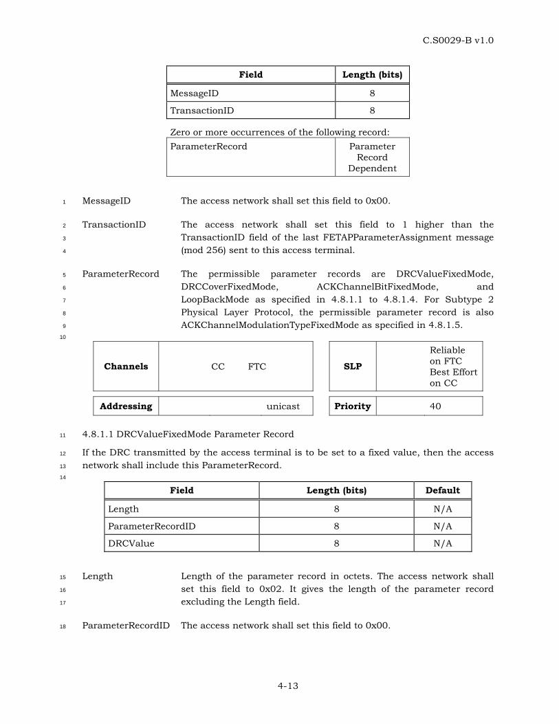
C.S0029-B v1.0
4-13
Field Length (bits)
MessageID 8
TransactionID 8
Zero or more occurrences of the following record: ParameterRecord Parameter
Record Dependent
MessageID The access network shall set this field to 0x00. 1
TransactionID The access network shall set this field to 1 higher than the 2
TransactionID field of the last FETAPParameterAssignment message 3
(mod 256) sent to this access terminal. 4
ParameterRecord The permissible parameter records are DRCValueFixedMode, 5
DRCCoverFixedMode, ACKChannelBitFixedMode, and 6
LoopBackMode as specified in 4.8.1.1 to 4.8.1.4. For Subtype 2 7
Physical Layer Protocol, the permissible parameter record is also 8
ACKChannelModulationTypeFixedMode as specified in 4.8.1.5. 9
10
Channels CC FTC SLP
Reliable on FTC Best Effort on CC
Addressing unicast Priority 40
4.8.1.1 DRCValueFixedMode Parameter Record 11
If the DRC transmitted by the access terminal is to be set to a fixed value, then the access 12
network shall include this ParameterRecord. 13
14
Field Length (bits) Default
Length 8 N/A
ParameterRecordID 8 N/A
DRCValue 8 N/A
Length Length of the parameter record in octets. The access network shall 15
set this field to 0x02. It gives the length of the parameter record 16
excluding the Length field. 17
ParameterRecordID The access network shall set this field to 0x00. 18
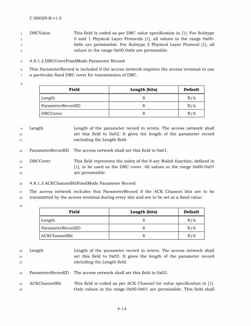
C.S0029-B v1.0
4-14
DRCValue This field is coded as per DRC value specification in [1]. For Subtype 1
0 and 1 Physical Layer Protocols [1], all values in the range 0x00-2
0x0c are permissible. For Subtype 2 Physical Layer Protocol [1], all 3
values in the range 0x00-0x0e are permissible. 4
4.8.1.2 DRCCoverFixedMode Parameter Record 5
This ParameterRecord is included if the access network requires the access terminal to use 6
a particular fixed DRC cover for transmission of DRC. 7
8
Field Length (bits) Default
Length 8 N/A
ParameterRecordID 8 N/A
DRCCover 8 N/A
Length Length of the parameter record in octets. The access network shall 9
set this field to 0x02. It gives the length of the parameter record 10
excluding the Length field. 11
ParameterRecordID The access network shall set this field to 0x01. 12
DRCCover This field represents the index of the 8-ary Walsh function, defined in 13
[1], to be used as the DRC cover. All values in the range 0x00-0x07 14
are permissible. 15
4.8.1.3 ACKChannelBitFixedMode Parameter Record 16
The access network includes this ParameterRecord if the ACK Channel bits are to be 17
transmitted by the access terminal during every slot and are to be set at a fixed value. 18
19
Field Length (bits) Default
Length 8 N/A
ParameterRecordID 8 N/A
ACKChannelBit 8 N/A
Length Length of the parameter record in octets. The access network shall 20
set this field to 0x02. It gives the length of the parameter record 21
excluding the Length field. 22
ParameterRecordID The access network shall set this field to 0x02. 23
ACKChannelBit This field is coded as per ACK Channel bit value specification in [1]. 24
Only values in the range 0x00-0x01 are permissible. This field shall 25
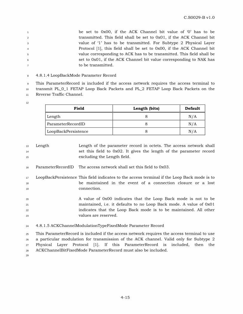
C.S0029-B v1.0
4-15
be set to 0x00, if the ACK Channel bit value of ‘0’ has to be 1
transmitted. This field shall be set to 0x01, if the ACK Channel bit 2
value of ‘1’ has to be transmitted. For Subtype 2 Physical Layer 3
Protocol [1], this field shall be set to 0x00, if the ACK Channel bit 4
value corresponding to ACK has to be transmitted. This field shall be 5
set to 0x01, if the ACK Channel bit value corresponding to NAK has 6
to be transmitted. 7
4.8.1.4 LoopBackMode Parameter Record 8
This ParameterRecord is included if the access network requires the access terminal to 9
transmit PL_0_1 FETAP Loop Back Packets and PL_2 FETAP Loop Back Packets on the 10
Reverse Traffic Channel. 11
12
Field Length (bits) Default
Length 8 N/A
ParameterRecordID 8 N/A
LoopBackPersistence 8 N/A
Length Length of the parameter record in octets. The access network shall 13
set this field to 0x02. It gives the length of the parameter record 14
excluding the Length field. 15
ParameterRecordID The access network shall set this field to 0x03. 16
LoopBackPersistence This field indicates to the access terminal if the Loop Back mode is to 17
be maintained in the event of a connection closure or a lost 18
connection. 19
A value of 0x00 indicates that the Loop Back mode is not to be 20
maintained, i.e. it defaults to no Loop Back mode. A value of 0x01 21
indicates that the Loop Back mode is to be maintained. All other 22
values are reserved. 23
4.8.1.5 ACKChannelModulationTypeFixedMode Parameter Record 24
This ParameterRecord is included if the access network requires the access terminal to use 25
a particular modulation for transmission of the ACK channel. Valid only for Subtype 2 26
Physical Layer Protocol [1]. If this ParameterRecord is included, then the 27
ACKChannelBitFixedMode ParameterRecord must also be included. 28
29
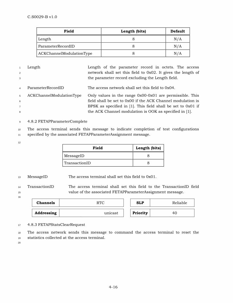
C.S0029-B v1.0
4-16
Field Length (bits) Default
Length 8 N/A
ParameterRecordID 8 N/A
ACKChannelModulationType 8 N/A
Length Length of the parameter record in octets. The access 1
network shall set this field to 0x02. It gives the length of 2
the parameter record excluding the Length field. 3
ParameterRecordID The access network shall set this field to 0x04. 4
ACKChannelModulationType Only values in the range 0x00-0x01 are permissible. This 5
field shall be set to 0x00 if the ACK Channel modulation is 6
BPSK as specified in [1]. This field shall be set to 0x01 if 7
the ACK Channel modulation is OOK as specified in [1]. 8
4.8.2 FETAPParameterComplete 9
The access terminal sends this message to indicate completion of test configurations 10
specified by the associated FETAPParameterAssignment message. 11
12
Field Length (bits)
MessageID 8
TransactionID 8
MessageID The access terminal shall set this field to 0x01. 13
TransactionID The access terminal shall set this field to the TransactionID field 14
value of the associated FETAPParameterAssignment message. 15
16
Channels RTC SLP Reliable
Addressing unicast Priority 40
4.8.3 FETAPStatsClearRequest 17
The access network sends this message to command the access terminal to reset the 18
statistics collected at the access terminal. 19
20
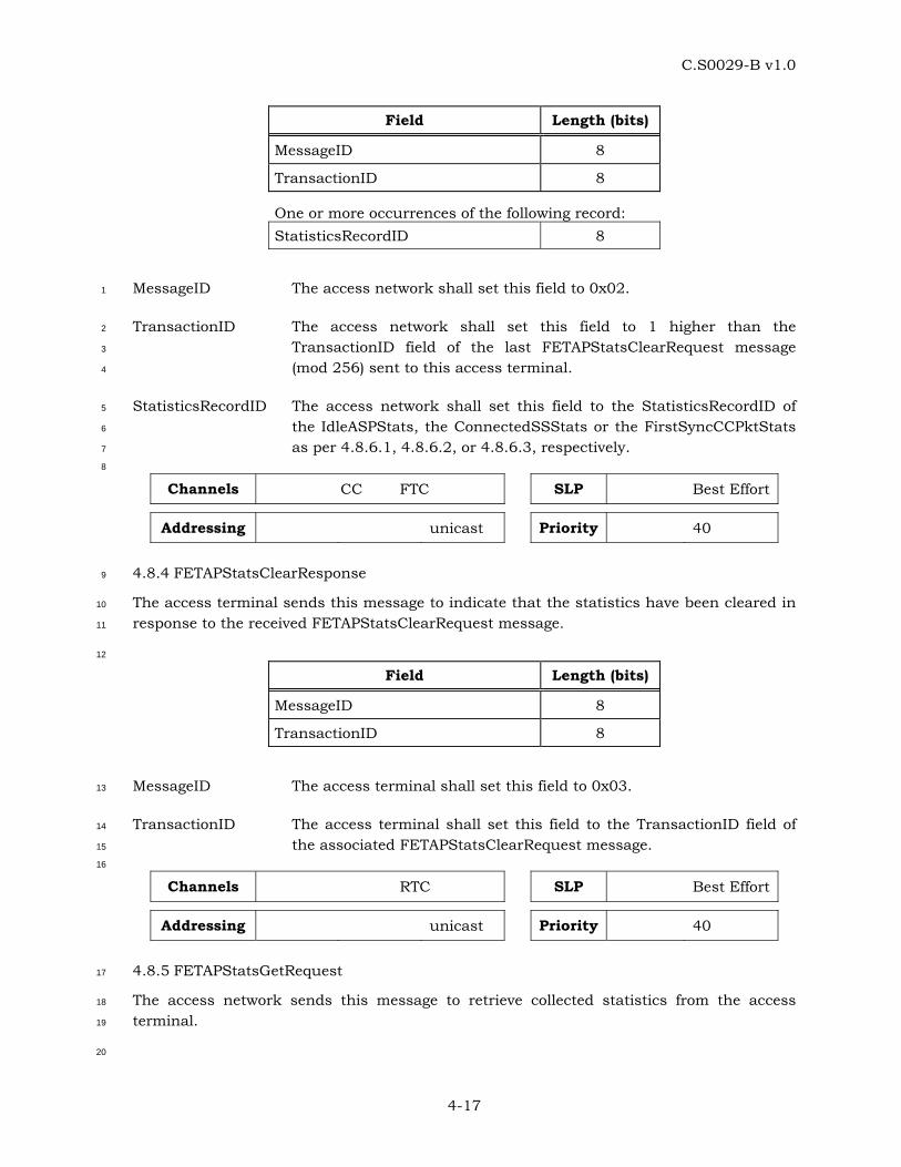
C.S0029-B v1.0
4-17
Field Length (bits)
MessageID 8
TransactionID 8
One or more occurrences of the following record: StatisticsRecordID 8
MessageID The access network shall set this field to 0x02. 1
TransactionID The access network shall set this field to 1 higher than the 2
TransactionID field of the last FETAPStatsClearRequest message 3
(mod 256) sent to this access terminal. 4
StatisticsRecordID The access network shall set this field to the StatisticsRecordID of 5
the IdleASPStats, the ConnectedSSStats or the FirstSyncCCPktStats 6
as per 4.8.6.1, 4.8.6.2, or 4.8.6.3, respectively. 7
8
Channels CC FTC SLP Best Effort
Addressing unicast Priority 40
4.8.4 FETAPStatsClearResponse 9
The access terminal sends this message to indicate that the statistics have been cleared in 10
response to the received FETAPStatsClearRequest message. 11
12
Field Length (bits)
MessageID 8
TransactionID 8
MessageID The access terminal shall set this field to 0x03. 13
TransactionID The access terminal shall set this field to the TransactionID field of 14
the associated FETAPStatsClearRequest message. 15
16
Channels RTC SLP Best Effort
Addressing unicast Priority 40
4.8.5 FETAPStatsGetRequest 17
The access network sends this message to retrieve collected statistics from the access 18
terminal. 19
20
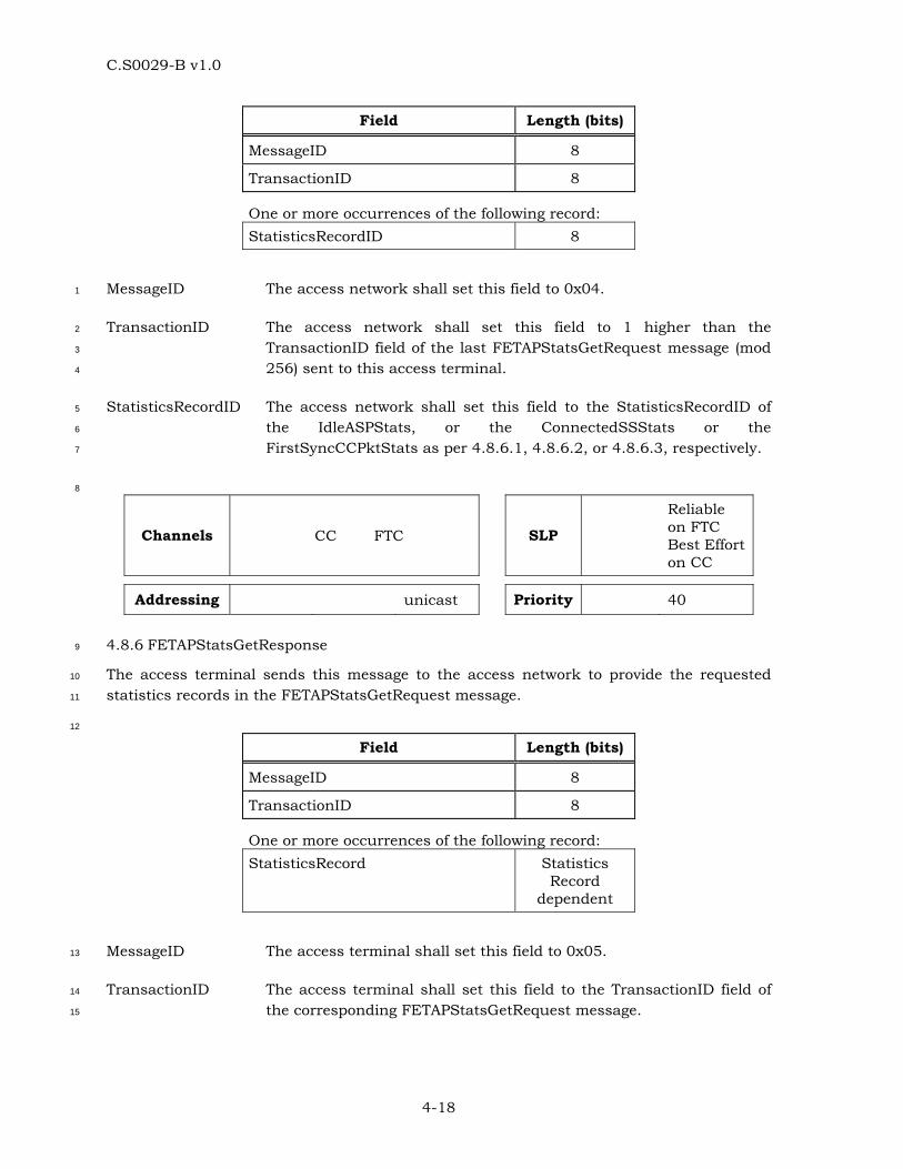
C.S0029-B v1.0
4-18
Field Length (bits)
MessageID 8
TransactionID 8
One or more occurrences of the following record: StatisticsRecordID 8
MessageID The access network shall set this field to 0x04. 1
TransactionID The access network shall set this field to 1 higher than the 2
TransactionID field of the last FETAPStatsGetRequest message (mod 3
256) sent to this access terminal. 4
StatisticsRecordID The access network shall set this field to the StatisticsRecordID of 5
the IdleASPStats, or the ConnectedSSStats or the 6
FirstSyncCCPktStats as per 4.8.6.1, 4.8.6.2, or 4.8.6.3, respectively. 7
8
Channels CC FTC SLP
Reliable on FTC Best Effort on CC
Addressing unicast Priority 40
4.8.6 FETAPStatsGetResponse 9
The access terminal sends this message to the access network to provide the requested 10
statistics records in the FETAPStatsGetRequest message. 11
12
Field Length (bits)
MessageID 8
TransactionID 8
One or more occurrences of the following record: StatisticsRecord Statistics
Record dependent
MessageID The access terminal shall set this field to 0x05. 13
TransactionID The access terminal shall set this field to the TransactionID field of 14
the corresponding FETAPStatsGetRequest message. 15

C.S0029-B v1.0
4-19
StatisticsRecord The IdleASPStats StatisticsRecord has the format as described in 1
4.8.6.1. The ConnectedSSStats StatisticsRecord has the format as 2
described in 4.8.6.2. The FirstSyncCCPktStats StatisticsRecord has 3
the format as described in 4.8.6.3. 4
5
Channels RTC SLP Reliable
Addressing unicast Priority 40
4.8.6.1 IdleASPStats Statistics Record 6
This StatisticsRecord provides the Active Set Pilot Change statistics collected by the access 7
terminal. 8
9
Field Length (bits) Default
Length 8 N/A
StatisticsRecordID 8 N/A
IdleASPChangeOverflow 1 0
IdleASPChange 15 0
IdleTimeOverflow 1 0
IdleTime 23 0
Length Length of the statistics record in octets. The access terminal 10
shall set this field to 0x06. It gives the length of the statistics 11
record excluding the Length field. 12
StatisticsRecordID The access terminal shall set this field to 0x04. 13
IdleASPChangeOverflow This bit shall be set to ‘1’ if the value of the IdleASPChange 14
statistics exceeds (215 –1). Otherwise, it shall be set to ‘0’, 15
IdleASPChange The value of IdleASPChange statistics mod 215. 16
IdleTimeOverflow This bit shall be set to ‘1’ if the value of the IdleTime statistics 17
exceeds (223 –1). Otherwise, it shall be set to ‘0’, 18
IdleTime The value of IdleTime statistics mod 223. 19
4.8.6.2 ConnectedSSStats Statistics Record 20
This StatisticsRecord provides the Serving Sector Change statistics collected by the access 21
terminal. 22
23
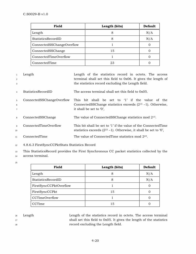
C.S0029-B v1.0
4-20
Field Length (bits) Default
Length 8 N/A
StatisticsRecordID 8 N/A
ConnectedSSChangeOverflow 1 0
ConnectedSSChange 15 0
ConnectedTimeOverflow 1 0
ConnectedTime 23 0
Length Length of the statistics record in octets. The access 1
terminal shall set this field to 0x06. It gives the length of 2
the statistics record excluding the Length field. 3
StatisticsRecordID The access terminal shall set this field to 0x05. 4
ConnectedSSChangeOverflow This bit shall be set to ‘1’ if the value of the 5
ConnectedSSChange statistics exceeds (215 –1). Otherwise, 6
it shall be set to ‘0’, 7
ConnectedSSChange The value of ConnectedSSChange statistics mod 215. 8
ConnectedTimeOverflow This bit shall be set to ‘1’ if the value of the ConnectedTime 9
statistics exceeds (223 –1). Otherwise, it shall be set to ‘0’, 10
ConnectedTime The value of ConnectedTime statistics mod 223. 11
4.8.6.3 FirstSyncCCPktStats Statistics Record 12
This StatisticsRecord provides the First Synchronous CC packet statistics collected by the 13
access terminal. 14
15
Field Length (bits) Default
Length 8 N/A
StatisticsRecordID 8 N/A
FirstSyncCCPktOverflow 1 0
FirstSyncCCPkt 15 0
CCTimeOverflow 1 0
CCTime 15 0
Length Length of the statistics record in octets. The access terminal 16
shall set this field to 0x05. It gives the length of the statistics 17
record excluding the Length field. 18
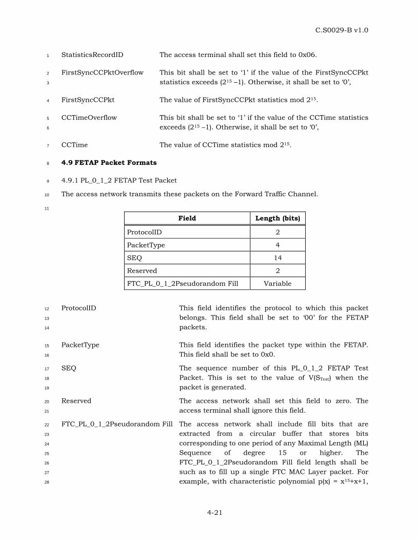
C.S0029-B v1.0
4-21
StatisticsRecordID The access terminal shall set this field to 0x06. 1
FirstSyncCCPktOverflow This bit shall be set to ‘1’ if the value of the FirstSyncCCPkt 2
statistics exceeds (215 –1). Otherwise, it shall be set to ‘0’, 3
FirstSyncCCPkt The value of FirstSyncCCPkt statistics mod 215. 4
CCTimeOverflow This bit shall be set to ‘1’ if the value of the CCTime statistics 5
exceeds (215 –1). Otherwise, it shall be set to ‘0’, 6
CCTime The value of CCTime statistics mod 215. 7
4.9 FETAP Packet Formats 8
4.9.1 PL_0_1_2 FETAP Test Packet 9
The access network transmits these packets on the Forward Traffic Channel. 10
11
Field Length (bits)
ProtocolID 2
PacketType 4
SEQ 14
Reserved 2
FTC_PL_0_1_2Pseudorandom Fill Variable
ProtocolID This field identifies the protocol to which this packet 12
belongs. This field shall be set to ‘00’ for the FETAP 13
packets. 14
PacketType This field identifies the packet type within the FETAP. 15
This field shall be set to 0x0. 16
SEQ The sequence number of this PL_0_1_2 FETAP Test 17
Packet. This is set to the value of V(STest) when the 18
packet is generated. 19
Reserved The access network shall set this field to zero. The 20
access terminal shall ignore this field. 21
FTC_PL_0_1_2Pseudorandom Fill The access network shall include fill bits that are 22
extracted from a circular buffer that stores bits 23
corresponding to one period of any Maximal Length (ML) 24
Sequence of degree 15 or higher. The 25
FTC_PL_0_1_2Pseudorandom Fill field length shall be 26
such as to fill up a single FTC MAC Layer packet. For 27
example, with characteristic polynomial p(x) = x15+x+1, 28
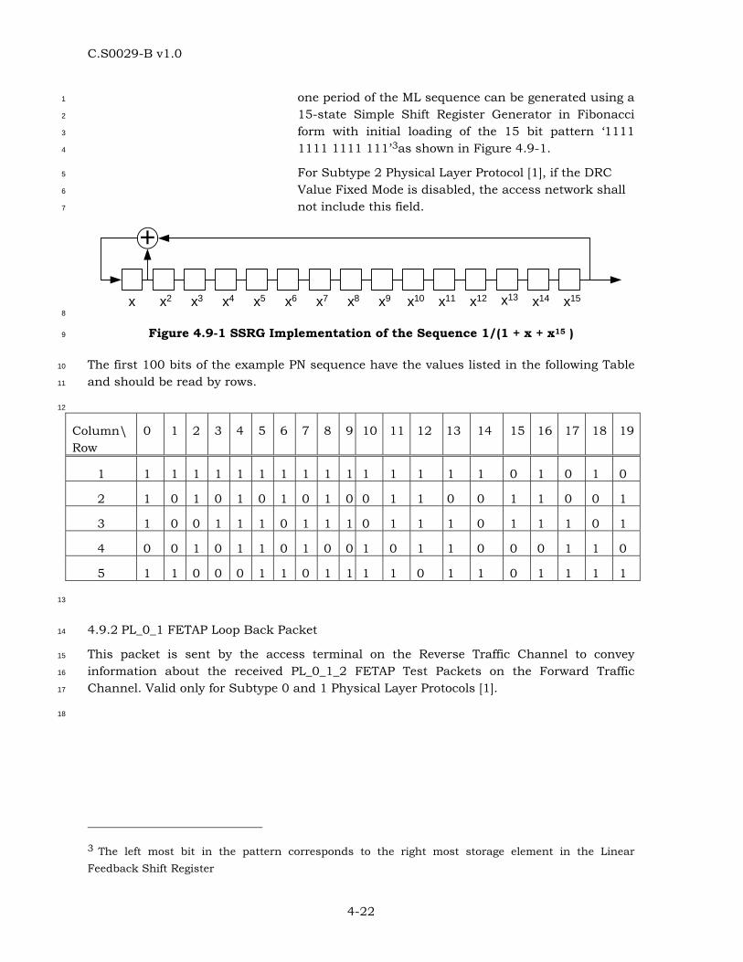
C.S0029-B v1.0
4-22
one period of the ML sequence can be generated using a 1
15-state Simple Shift Register Generator in Fibonacci 2
form with initial loading of the 15 bit pattern ‘1111 3
1111 1111 111’3as shown in Figure 4.9-1. 4
For Subtype 2 Physical Layer Protocol [1], if the DRC 5
Value Fixed Mode is disabled, the access network shall 6
not include this field. 7
+
x x2 x3 x4 x5 x6 x7 x8 x9 x10 x11 x12 x13 x14 x15 8
Figure 4.9-1 SSRG Implementation of the Sequence 1/(1 + x + x15 ) 9
The first 100 bits of the example PN sequence have the values listed in the following Table 10
and should be read by rows. 11
12
Column\ Row
0 1 2 3 4 5 6 7 8 9 10 11 12 13 14 15 16 17 18 19
1 1 1 1 1 1 1 1 1 1 1 1 1 1 1 1 0 1 0 1 0
2 1 0 1 0 1 0 1 0 1 0 0 1 1 0 0 1 1 0 0 1
3 1 0 0 1 1 1 0 1 1 1 0 1 1 1 0 1 1 1 0 1
4 0 0 1 0 1 1 0 1 0 0 1 0 1 1 0 0 0 1 1 0
5 1 1 0 0 0 1 1 0 1 1 1 1 0 1 1 0 1 1 1 1
13
4.9.2 PL_0_1 FETAP Loop Back Packet 14
This packet is sent by the access terminal on the Reverse Traffic Channel to convey 15
information about the received PL_0_1_2 FETAP Test Packets on the Forward Traffic 16
Channel. Valid only for Subtype 0 and 1 Physical Layer Protocols [1]. 17
18
3 The left most bit in the pattern corresponds to the right most storage element in the Linear Feedback Shift Register

C.S0029-B v1.0
4-23
Field Length (bits)
ProtocolID 2
PacketType 4
PL_0_1_2FwdSysTime 15
LBPktOverflow 1
RecordCount 5
Up to RecordCount occurrences of the following record: TCAMsgSeqIncluded 1
TCAMsgSeq 0 or 8
DRCCover 3
FwdPhysSlots 4
PL_0_1FwdMACPkts 2
FwdSeqIncluded 1
FwdSeq 0 or 14
Reserved variable
ProtocolID This field identifies the protocol to which this packet belongs. This 1
field shall be set to ‘00’ for the FETAP packets. 2
PacketType This field identifies the packet type within the FETAP. This field 3
shall be set to 0x1. 4
PL_0_1_2FwdSysTime CDMA System Time in frames mod 32768 corresponding to the 5
start (0th slot) of the 16-slot observation interval covered by this 6
PL_0_1 FETAP Loop Back Packet. 7
LBPktOverflow This field indicates if any PL_0_1 FETAP Loop Back Packets were 8
lost due to buffer overflow. It is set to the value of the 9
LBOverflowBit (see 4.7.4.1). 10
RecordCount This is the number of PL_0_1_2 FETAP Test Packet Records 11
associated with the observation interval. If no PL_0_1_2 FETAP 12
Test Packet Records are included, this field shall be set to 0. The 13
valid range for this field shall be 0 through 16. 14
TCAMsgSeqIncluded For the first record this field shall be set to ‘1’. For subsequent 15
records, if the TCAMsgSeq value is the same as the last record, 16
then this field shall be set to ‘0’. Otherwise, this field shall be set 17
to ‘1’. 18
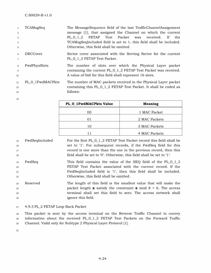
C.S0029-B v1.0
4-24
TCAMsgSeq The MessageSequence field of the last TrafficChannelAssignment 1
message [1], that assigned the Channel on which the current 2
PL_0_1_2 FETAP Test Packet was received. If the 3
TCAMsgSeqIncluded field is set to 1, this field shall be included. 4
Otherwise, this field shall be omitted. 5
DRCCover Sector cover associated with the Serving Sector for the current 6
PL_0_1_2 FETAP Test Packet. 7
FwdPhysSlots The number of slots over which the Physical Layer packet 8
containing the current PL_0_1_2 FETAP Test Packet was received. 9
A value of 0x0 for this field shall represent 16 slots. 10
PL_0_1FwdMACPkts The number of MAC packets received in the Physical Layer packet 11
containing this PL_0_1_2 FETAP Test Packet. It shall be coded as 12
follows: 13
14
PL_0_1FwdMACPkts Value Meaning
00 1 MAC Packet
01 2 MAC Packets
10 3 MAC Packets
11 4 MAC Packets
FwdSeqIncluded For the first PL_0_1_2 FETAP Test Packet record this field shall be 15
set to ‘1’. For subsequent records, if the FwdSeq field for this 16
record is one more than the one in the previous record, then this 17
field shall be set to ‘0’. Otherwise, this field shall be set to ‘1’. 18
FwdSeq This field contains the value of the SEQ field of the PL_0_1_2 19
FETAP Test Packet associated with the current record. If the 20
FwdSeqIncluded field is ‘1’, then this field shall be included. 21
Otherwise, this field shall be omitted. 22
Reserved The length of this field is the smallest value that will make the 23
packet length x satisfy the constraint x mod 8 = 6. The access 24
terminal shall set this field to zero. The access network shall 25
ignore this field. 26
4.9.3 PL_2 FETAP Loop Back Packet 27
This packet is sent by the access terminal on the Reverse Traffic Channel to convey 28
information about the received PL_0_1_2 FETAP Test Packets on the Forward Traffic 29
Channel. Valid only for Subtype 2 Physical Layer Protocol [1]. 30
31
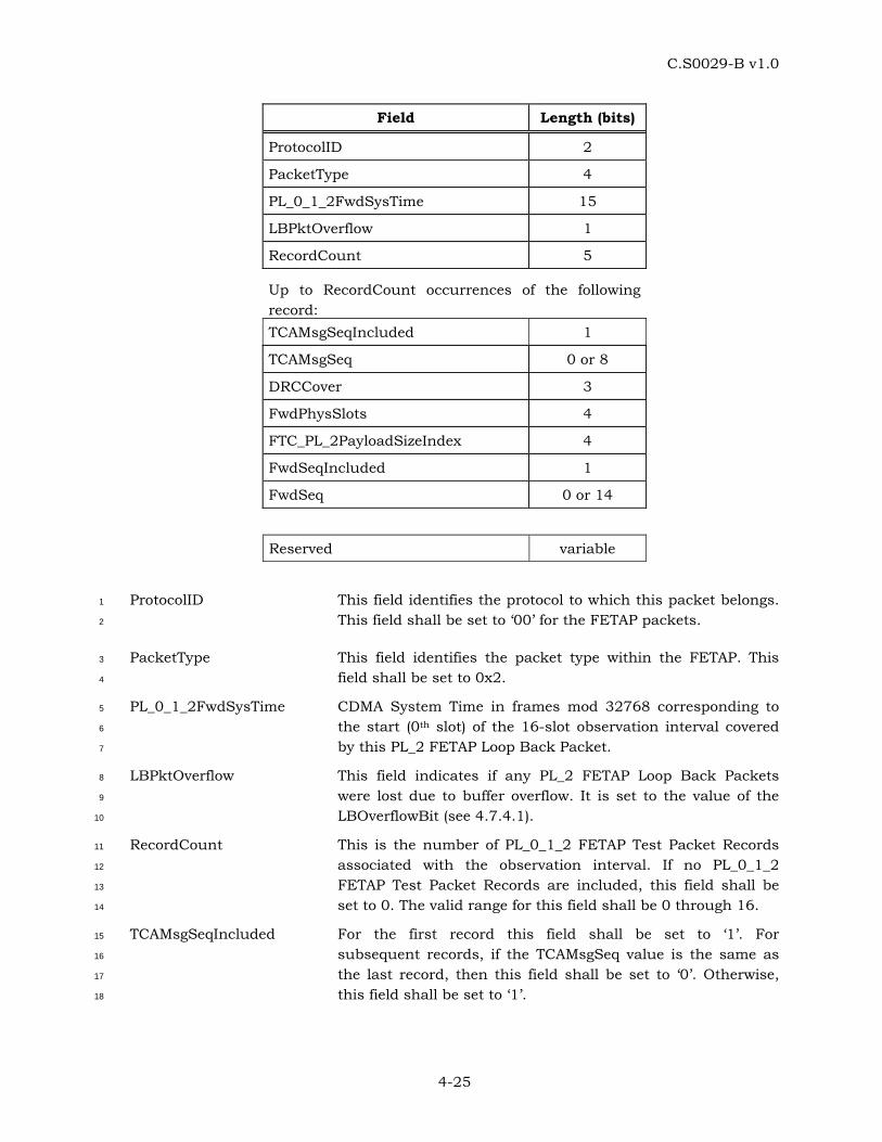
C.S0029-B v1.0
4-25
Field Length (bits)
ProtocolID 2
PacketType 4
PL_0_1_2FwdSysTime 15
LBPktOverflow 1
RecordCount 5
Up to RecordCount occurrences of the following record: TCAMsgSeqIncluded 1
TCAMsgSeq 0 or 8
DRCCover 3
FwdPhysSlots 4
FTC_PL_2PayloadSizeIndex 4
FwdSeqIncluded 1
FwdSeq 0 or 14
Reserved variable
ProtocolID This field identifies the protocol to which this packet belongs. 1
This field shall be set to ‘00’ for the FETAP packets. 2
PacketType This field identifies the packet type within the FETAP. This 3
field shall be set to 0x2. 4
PL_0_1_2FwdSysTime CDMA System Time in frames mod 32768 corresponding to 5
the start (0th slot) of the 16-slot observation interval covered 6
by this PL_2 FETAP Loop Back Packet. 7
LBPktOverflow This field indicates if any PL_2 FETAP Loop Back Packets 8
were lost due to buffer overflow. It is set to the value of the 9
LBOverflowBit (see 4.7.4.1). 10
RecordCount This is the number of PL_0_1_2 FETAP Test Packet Records 11
associated with the observation interval. If no PL_0_1_2 12
FETAP Test Packet Records are included, this field shall be 13
set to 0. The valid range for this field shall be 0 through 16. 14
TCAMsgSeqIncluded For the first record this field shall be set to ‘1’. For 15
subsequent records, if the TCAMsgSeq value is the same as 16
the last record, then this field shall be set to ‘0’. Otherwise, 17
this field shall be set to ‘1’. 18
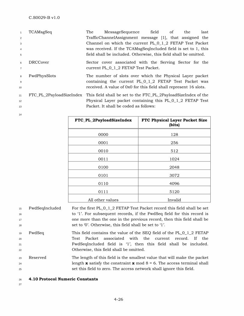
C.S0029-B v1.0
4-26
TCAMsgSeq The MessageSequence field of the last 1
TrafficChannelAssignment message [1], that assigned the 2
Channel on which the current PL_0_1_2 FETAP Test Packet 3
was received. If the TCAMsgSeqIncluded field is set to 1, this 4
field shall be included. Otherwise, this field shall be omitted. 5
DRCCover Sector cover associated with the Serving Sector for the 6
current PL_0_1_2 FETAP Test Packet. 7
FwdPhysSlots The number of slots over which the Physical Layer packet 8
containing the current PL_0_1_2 FETAP Test Packet was 9
received. A value of 0x0 for this field shall represent 16 slots. 10
FTC_PL_2PayloadSizeIndex This field shall be set to the FTC_PL_2PayloadSizeIndex of the 11
Physical Layer packet containing this PL_0_1_2 FETAP Test 12
Packet. It shall be coded as follows: 13
14
FTC_PL_2PayloadSizeIndex FTC Physical Layer Packet Size (bits)
0000 128
0001 256
0010 512
0011 1024
0100 2048
0101 3072
0110 4096
0111 5120
All other values Invalid
FwdSeqIncluded For the first PL_0_1_2 FETAP Test Packet record this field shall be set 15
to ‘1’. For subsequent records, if the FwdSeq field for this record is 16
one more than the one in the previous record, then this field shall be 17
set to ‘0’. Otherwise, this field shall be set to ‘1’. 18
FwdSeq This field contains the value of the SEQ field of the PL_0_1_2 FETAP 19
Test Packet associated with the current record. If the 20
FwdSeqIncluded field is ‘1’, then this field shall be included. 21
Otherwise, this field shall be omitted. 22
Reserved The length of this field is the smallest value that will make the packet 23
length x satisfy the constraint x mod 8 = 6. The access terminal shall 24
set this field to zero. The access network shall ignore this field. 25
4.10 Protocol Numeric Constants 26
27
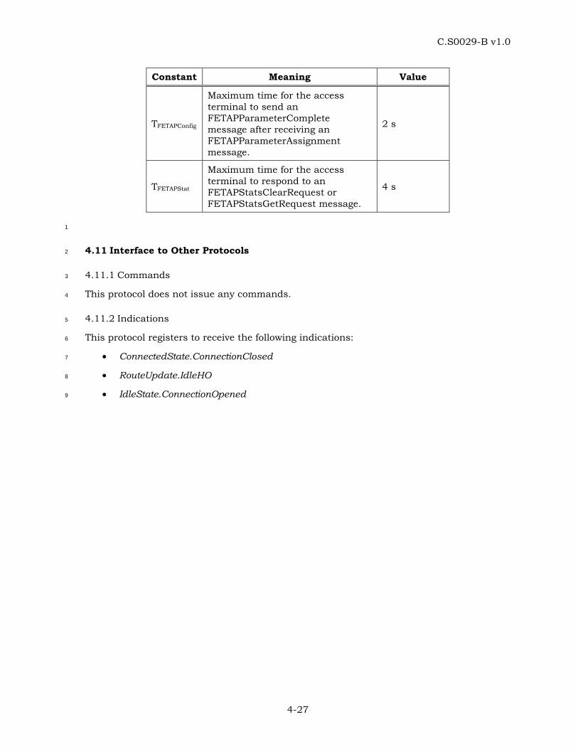
C.S0029-B v1.0
4-27
Constant Meaning Value
TFETAPConfig
Maximum time for the access terminal to send an FETAPParameterComplete message after receiving an FETAPParameterAssignment message.
2 s
TFETAPStat
Maximum time for the access terminal to respond to an FETAPStatsClearRequest or FETAPStatsGetRequest message.
4 s
1
4.11 Interface to Other Protocols 2
4.11.1 Commands 3
This protocol does not issue any commands. 4
4.11.2 Indications 5
This protocol registers to receive the following indications: 6
• ConnectedState.ConnectionClosed 7
• RouteUpdate.IdleHO 8
• IdleState.ConnectionOpened 9

C.S0029-B v1.0
5-1
5 REVERSE ENHANCED TEST APPLICATION PROTOCOL (RETAP) SPECIFICATION 1
5.1 Overview 2
The Reverse Enhanced Test Application Protocol (RETAP) provides the procedures and 3
messages used by the access network and the access terminal to: 4
• Control RETAP test configurations at both the access terminal and the access 5
network. 6
• Generate PL_0_1 RETAP Test Packets and PL_0_1 RETAP Fill Packets at the access 7
terminal for transmission on the Reverse Traffic Channel, and process the received 8
packets at the access network. 9
• Transmit packets at configured Reverse Traffic Channel rates. Valid only for 10
Subtype 0 and 1 Physical Layer Protocols [1]. 11
• Generate PL_2 RETAP Test Packets at the access terminal for transmission on the 12
Reverse Traffic Channel, and process the received packets at the access network. 13
Includes support for multiple concurrent MAC flows as specified in Subtype 3 RTC 14
MAC Protocol [1]. 15
• Transmit packets at the configured Reverse Traffic Channel payload sizes. Valid 16
only for Subtype 2 Physical Layer Protocol [1]. 17
• Transmit packets at the configured Enhanced Access Channel rates. Valid only for 18
Subtype 1 and 2 Physical Layer Protocols [1]. 19
• RETAP does not operate with Subtype 2 Reverse Traffic Channel MAC Protocol. 20
Throughout this section, the notation ‘PL_0_1’ refers to Subtype 0 or 1 Physical Layer 21
Protocol [1] applicability. The notation ‘PL_2’ refers to Subtype 2 Physical Layer Protocol [1] 22
applicability. 23
5.2 Data Encapsulation 24
In the transmit direction, the RETAP generates test packets and forwards them to the 25
stream layer. 26
In the receive direction the RETAP receives test packets from the stream layer and 27
processes them. 28
Figure 5.2-1 illustrates the relationship between the RETAP packets and the Stream Layer 29
payload. 30
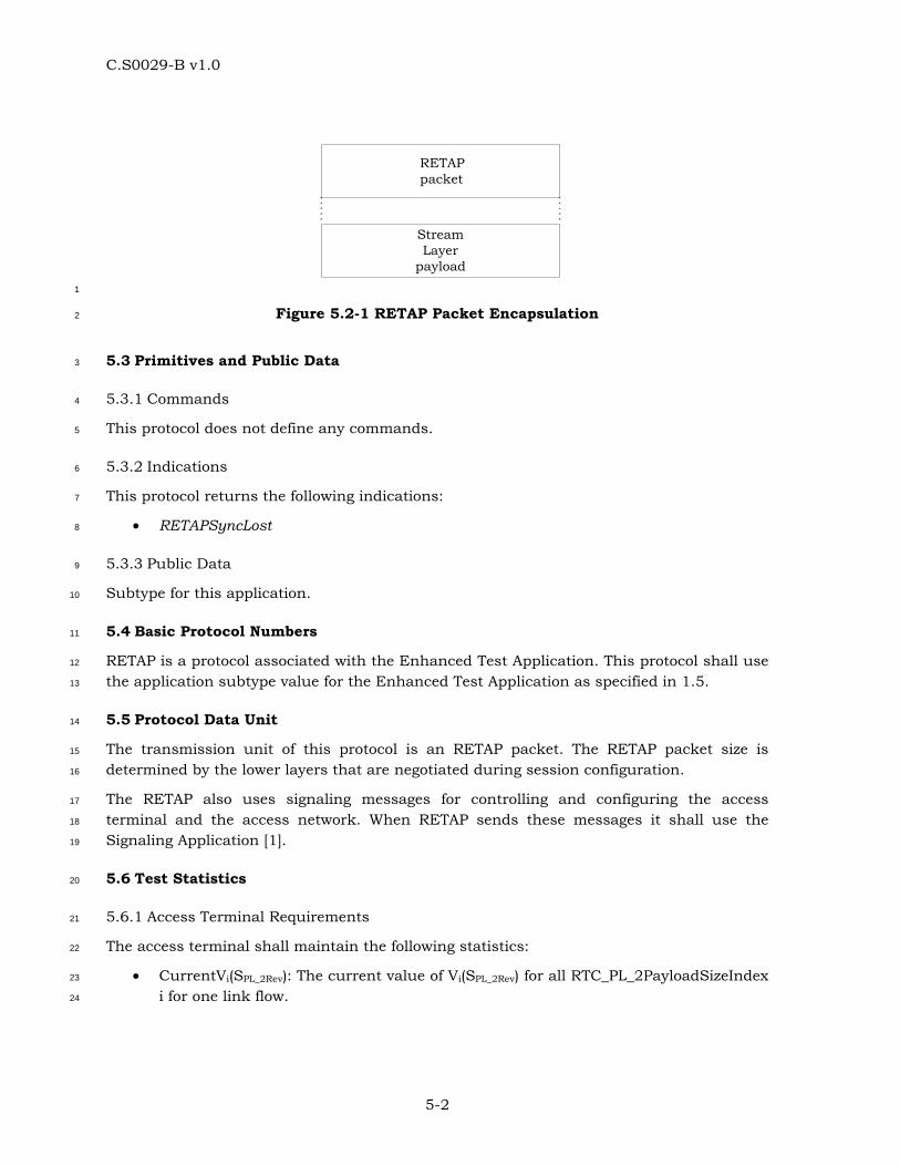
C.S0029-B v1.0
5-2
StreamLayer
payload
RETAPpacket
1
Figure 5.2-1 RETAP Packet Encapsulation 2
5.3 Primitives and Public Data 3
5.3.1 Commands 4
This protocol does not define any commands. 5
5.3.2 Indications 6
This protocol returns the following indications: 7
• RETAPSyncLost 8
5.3.3 Public Data 9
Subtype for this application. 10
5.4 Basic Protocol Numbers 11
RETAP is a protocol associated with the Enhanced Test Application. This protocol shall use 12
the application subtype value for the Enhanced Test Application as specified in 1.5. 13
5.5 Protocol Data Unit 14
The transmission unit of this protocol is an RETAP packet. The RETAP packet size is 15
determined by the lower layers that are negotiated during session configuration. 16
The RETAP also uses signaling messages for controlling and configuring the access 17
terminal and the access network. When RETAP sends these messages it shall use the 18
Signaling Application [1]. 19
5.6 Test Statistics 20
5.6.1 Access Terminal Requirements 21
The access terminal shall maintain the following statistics: 22
• CurrentVi(SPL_2Rev): The current value of Vi(SPL_2Rev) for all RTC_PL_2PayloadSizeIndex 23
i for one link flow. 24
C.S0029-B v1.0
5-3
• Stats_PL_2RevSysTime: CDMA System Time in sub-frames mod 549755813888 for 1
one link flow corresponding to the slot boundary that begins the transmission of the 2
current RTC MAC Packet. 3
5.6.2 Access Network Requirements 4
The access network may maintain the following statistics: 5
• PL_0_1RTCMACPktSent[i]: An array whose (i+1)th element contains the number of 6
RTC MAC Packets that were sent by the access terminal at a rate corresponding to 7
the RTC_PL_0_1RateIndex i, as per Table 5.8.1.2-1. 8
• PL_2RTCMACPktSent[i]: An array whose (i+1)th element contains the number of RTC 9
MAC Packets that were sent by the access terminal at a payload size corresponding 10
to the RTC_PL_2PayloadSizeIndex i, as per Table 5.8.1.3-1. 11
• PL_0_1RTCMACPktRecd[i]: An array whose (i+1)th element contains the number of 12
RTC MAC Packets that were received by the access network at a rate corresponding 13
to the RTC_PL_0_1RateIndex i, as per Table 5.8.1.2-1. 14
• PL_2RTCMACPktRecd[i]: An array whose (i+1)th element contains the number of RTC 15
MAC Packets that were received by the access network at a rate corresponding to 16
the RTC_PL_2PayloadSizeIndex i, as per Table 5.8.1.3-1. 17
• PL_2TargetRTCMACPktRecd[i]: For Low Latency mode [1], an array whose (i+1)th 18
element contains the number of RTC MAC Packets that were received within 19
LoLatTerminationTargetPS [1] by the access network at a rate corresponding to 20
RTC_PL_2PayloadSizeIndex i, as per Table 5.8.1.3-1. For High Capacity mode [1], an 21
array whose (i+1)th element contains the number of RTC MAC Packets that were 22
received within HiCapTerminationTargetPS [1] by the access network at a rate 23
corresponding to RTC_PL_2PayloadSizeIndex i, as per Table 5.8.1.3-1. 24
• PL_2RETAPPhysPktSlots[i]: Array whose (i+1)th element contains the number of slots 25
over which the RTC MAC Packets were received by the access network 26
corresponding to the RTC_PL_2PayloadSizeIndex i as per 27
RTC_PL_2PayloadSizeIndex i, as per Table 5.8.1.3-1. 28
• PL_0_1RETAPTestTime: The duration of the RETAP test in frames. 29
• PL_2RETAPTestTime: The duration of the RETAP test in sub-frames. 30
• RTC_PL_2PayloadSizeIndex i(t): The RTC_PL_2PayloadSizeIndex i, as per Table 31
5.8.1.3-1, as a function of CDMA System Time in sub-frames, of an RTC MAC 32
Packet received by the access network. 33
• RTC_PL_2StreamLayerPayloadSize j(t): The RTC_PL_2StreamLayerPayloadSize j, as 34
a function of CDMA System Time in sub-frames, of a link flow j in an RTC MAC 35
Packet received by the access network. 36
5.7 Procedures 37
The RETAP is specified by the following procedures, which control and configure different 38
aspects of the Reverse Traffic Channel tests. 39
C.S0029-B v1.0
5-4
• Test Parameter Configuration: Procedures and messages for configuring test 1
parameters. 2
• Access Terminal Statistics Collection and Retrieval: Procedures and messages for 3
resetting the statistics being collected at the access terminal and for retrieving 4
them. 5
• RETAP Packet Transmission and Reception: Procedures for sending and receiving 6
PL_0_1 RETAP Test Packets and PL_0_1 RETAP Fill Packets on the Reverse Traffic 7
Channel. Procedures for sending and receiving PL_2 RETAP Test Packets on the 8
Reverse Traffic Channel. 9
5.7.1 Test Parameter Configuration 10
5.7.1.1 Access Terminal Requirements 11
When the protocol is instantiated, the access terminal shall execute the configuration 12
initialization procedure in 5.7.1.1.1. 13
When the protocol receives a ConnectedState.ConnectionClosed [1] indication, the access 14
terminal shall execute the configuration initialization procedure in 5.7.1.1.2. 15
If the access terminal receives an RETAPParameterAssignment message, it shall do the 16
following steps in sequence: 17
• Execute the configuration initialization procedure in 5.7.1.1.1. 18
• Execute the test parameter initialization procedure in 5.7.1.1.3. 19
• For Subtype 0 and 1 Physical Layer Protocols [1], if the message includes the 20
RETAPTestPktEnable parameter record, then the RETAP Test Packet mode is 21
enabled, and the value of the RETAPTestPktPersistence field is stored. The RETAP 22
Test Packet buffer is cleared and the RETAPTestPktOverflowBit is set to ‘0’ (see 23
5.7.3.1.1). 24
• For Subtype 2 Physical Layer Protocol [1], if the message includes the 25
RETAPTestPktEnable parameter record, then the RETAP Test Packet mode is 26
enabled, and the value of the RETAPTestPktPersistence field is stored. 27
• If the message includes the PacketRateMode parameter record, then the Configured 28
Packet Rate mode is enabled. The values of the MinRateIndex and MaxRateIndex 29
fields are stored (see 5.7.3.1.2). 30
• If the message includes the PacketPayloadSizeMode parameter record, then the 31
Configured Packet Payload Size mode is enabled. The values of the 32
MinPayloadSizeIndex and MaxPayloadSizeIndex fields are stored (see 5.7.3.1.3). 33
• If the message includes the EnhancedAccessChannelRateMode parameter record, 34
then the Configured Enhanced Access Channel Rate mode is enabled. 35
• If the message includes the BurstPeriodMode parameter record, then the 36
Configured Burst Period mode is enabled. The values of the BurstPeriod and 37
LinkFlowID fields are stored (see 5.8.1.5). If the message includes the 38
C.S0029-B v1.0
5-5
BurstSizeMode parameter record, then the Configured Burst Size mode is enabled. 1
The values of the BurstSize and LinkFlowID fields are stored (see 5.8.1.6). 2
• Send an RETAPParameterComplete message. The TransactionID field shall be set to 3
the same value as that received in the RETAPParameterAssignment message. The 4
RETAPParameterComplete message shall be sent within TRETAPConfig from when the 5
RETAPParameterAssignment message is received. 6
5.7.1.1.1 Access Terminal Configuration Initialization 7
When the protocol is instantiated or an RETAPParameterAssignment message is received, 8
the access terminal shall initialize the test configuration as follows: 9
• The RETAP Test Packet mode is disabled. 10
• The Configured Packet Rate mode is disabled. 11
• The Configured Packet Payload Size mode is disabled. 12
• The Configured Enhanced Access Channel Rate mode is disabled. 13
• The Configured Burst Period mode is disabled. 14
• The Configured Burst Size mode is disabled. 15
5.7.1.1.2 Access Terminal Configuration for Closed or Lost Connection 16
When the protocol receives a ConnectedState.ConnectionClosed indication [1], the access 17
terminal shall initialize the test configuration as follows: 18
• If the RETAP Test Packet mode is enabled, and the value of the 19
RETAPTestPktPersistence field of the RETAPTestPktEnable parameter record in the 20
last received RETAPParameterAssignment message is ‘00’, then the RETAP Test 21
Packet mode is disabled. 22
• The Configured Packet Rate mode is disabled. 23
• The Configured Packet Payload Size mode is disabled. 24
• The Configured Enhanced Access Channel Rate mode is disabled, unless the access 25
terminal received an RETAPParameterAssignment message containing the 26
EnhancedAccessChannelRateMode parameter record while in connected state. 27
• The Configured Burst Period mode is disabled. 28
• The Configured Burst Size mode is disabled. 29
5.7.1.1.3 Access Terminal Test Parameter Initialization 30
For Subtype 0 and 1 Physical Layer Protocols [1], the access terminal shall set Vi(SPL_0_1Rev), 31
the 12-bit sequence number associated with RTC MAC Packets transmitted at the rate 32
corresponding to RTC_PL_0_1RateIndex i (Table 5.8.1.2-1), to zero, for all possible RTC 33
rates [1]. 34
For Subtype 2 Physical Layer Protocol [1], the access terminal shall set Vi(SPL_2Rev), the 32-35
bit sequence number associated with RTC MAC Packets transmitted using payload sizes 36
C.S0029-B v1.0
5-6
corresponding to RTC_PL_2PayloadSizeIndex i (Table 5.8.1.3-1) to zero for one link flow, for 1
all possible RTC payload sizes. 2
5.7.1.2 Access Network Requirements 3
To change the test configuration the access network shall perform the following steps: 4
• Send an RETAPParameterAssignment message to the access terminal and wait for 5
an RETAPParameterComplete message containing the same TransactionID as that 6
in the RETAPParameterAssignment message. 7
• When the expected RETAPParameterComplete message is received, execute the Test 8
Statistics Initialization procedure in 5.7.1.2.1. 9
5.7.1.2.1 Access Network Test Statistics Initialization 10
The access network shall set the test statistics as follows: 11
• PL_0_1RTCMACPktSent[i] to zero for all possible i. 12
• PL_2RTCMACPktSent[i] to zero for all possible i. 13
• PL_0_1RTCMACPktRecd[i] to zero for all possible i. 14
• PL_2RTCMACPktRecd[i] to zero for all possible i. 15
• PL_2RETAPPhysPktSlots[i] to zero for all possible i. 16
• PL_2TargetRTCMACPktRecd[i] to zero for all possible i. 17
• PL_0_1RETAPTestTime to zero. 18
• PL_2RETAPTestTime to zero. 19
• RTC_PL_2PayloadSizeIndex i(t) to zero for all i. 20
• RTC_PL_2StreamLayerPayloadSize j(t) to zero for all j. 21
5.7.2 Access Terminal Statistics Collection and Retrieval 22
5.7.2.1 Access Terminal Requirements 23
When the protocol is instantiated, the access terminal shall execute the Statistics 24
Initialization procedure in 5.7.2.1.1. 25
If the access terminal receives an RETAPStatsClearRequest message, the access terminal 26
shall 27
• execute the Statistics Initialization procedure as follows: 28
o If StatisticsRecordID is equal to 0x00, set PhysLaySubTyp2Seq_i for all 29
RTC_PL_2PayloadSizeIndex i and Stats_PL_2RevSysTime to zero. 30
• send an RETAPStatsClearResponse message within TRETAPStat. 31
When the Air Link Management Protocol is in the Connected State and the RETAP Test 32
Packet mode is enabled 33
C.S0029-B v1.0
5-7
• PhysLaySubTyp2Seq_i for one link flow shall be incremented whenever an RTC MAC 1
Packet at a payload size with RTC_PL_2PayloadSizeIndex i (see Table 5.8.1.3-1) is 2
generated. 3
• Stats_PL_2RevSysTime shall reflect current CDMA System Time in frames mod 4
549755813888 for one link flow corresponding to the slot boundary that begins the 5
transmission of the current RTC MAC Packet. 6
If the access terminal receives an RETAPStatsGetRequest message, it shall respond within 7
TRETAPStat with an RETAPStatsGetResponse containing the requested statistics records. 8
5.7.2.1.1 Statistics Initialization 9
The access terminal shall set 10
• PhysLaySubTyp2Seq_i for one link flow to 0 for all RTC_PL_2PayloadSizeIndex i. 11
• Stats_PL_2RevSysTime for one link flow to 0. 12
5.7.2.2 Access Network Requirements 13
To reset statistics collected at the access terminal, the access network shall send an 14
RETAPStatsClearRequest message and wait for an RETAPStatsClearResponse message 15
containing the same TransactionID as that in the RETAPStatsClearRequest message. 16
Reception of the expected RETAPStatsClearResponse message indicates that the test 17
statistics at the access terminal have been cleared. 18
To retrieve the statistics collected at the access terminal, the access network shall send an 19
RETAPStatsGetRequest message and wait for an RETAPStatsGetResponse message 20
containing the same TransactionID as that in the RETAPStatsGetRequest message. 21
5.7.3 PL_0_1 RETAP Packet and PL_2 RETAP Packet Transmission and Reception 22
5.7.3.1 Access Terminal Requirements 23
5.7.3.1.1 Generation and Transmission 24
For Subtype 0 and 1 Physical Layer Protocols [1], if the RETAP Test Packet mode is 25
enabled, the access terminal shall generate a PL_0_1 RETAP Test Packet at the beginning of 26
every 16-slot interval aligned to the CDMA System Time [1] in frames. 27
For Subtype 2 Physical Layer Protocol [1], if the RETAP Test Packet mode is enabled, the 28
access terminal shall generate a PL_2 RETAP Test Packet for a link flow, as appropriate, for 29
every 4-slot interval aligned to the CDMA System Time that begins a new transmission of 30
an RTC MAC Packet containing a PL_2 RETAP Test Packet. The access terminal shall 31
increment the sequence number Vi(SPL_2Rev) for every 4-slot interval aligned to the CDMA 32
System Time that begins a new transmission of an RTC MAC Packet. 33
The access terminal shall obey the following rules: 34
• The PL_0_1 RETAP Test Packets and PL_2 RETAP Test Packets shall be generated 35
only in the Connected State of the Air Link Management Protocol. 36
C.S0029-B v1.0
5-8
• The information contained in the PL_0_1 RETAP Test Packet (see 5.9.1) shall cover 1
RTC MAC Packets transmitted up to, but not including, the time instant of 2
generation. 3
• The information contained in the PL_2 RETAP Test Packet (see 5.9.3) shall cover the 4
current RTC MAC Packet. 5
• The access terminal shall assign a transmission priority of 55 to PL_0_1 RETAP Test 6
Packets and PL_2 RETAP Test Packets. 7
• For Subtype 0 and 1 Physical Layer Protocols [1], the transmission rate for the RTC 8
MAC Packet shall be determined as specified in 5.7.3.1.2. 9
• For Subtype 2 Physical Layer Protocol [1], the payload size of the RTC MAC Packet 10
shall be determined as specified in 5.7.3.1.3. 11
• The access terminal shall queue the generated PL_0_1 RETAP Test Packets. The 12
access terminal shall provide buffering for at least 16 PL_0_1 RETAP Test Packets. 13
The RETAPTestPktOverflowBit indicates if any PL_0_1 RETAP Test Packets have 14
been lost due to lack of buffer space. When a packet is lost due to lack of buffer 15
space, the RETAPTestPktOverflowBit shall be set to ‘1’. 16
The access terminal shall follow the following rules for transmitting a PL_0_1 RETAP Test 17
Packet and PL_2 RETAP Test Packet: 18
• The access terminal shall transmit the queued PL_0_1 RETAP Test Packets in the 19
Connected State of the Air Link Management Protocol [1]. 20
• The access terminal shall transmit the PL_2 RETAP Test Packets in the Connected 21
State of the Air Link Management Protocol [1]. 22
• If the Configured Packet Rate mode is enabled, the access terminal shall transmit a 23
PL_0_1 RETAP Fill Packet of the size necessary for the RTC MAC Packet containing 24
the PL_0_1 RETAP Test Packet at the selected rate. The access terminal shall set the 25
priority of the PL_0_1 RETAP Fill Packet to 255. 26
• When the access terminal transmits an RTC MAC Packet at a rate with 27
RTC_PL_0_1RateIndex i (Table 5.8.1.2-1), it shall increment the sequence number 28
Vi(SPL_0_1Rev). 29
• When the access terminal transmits an RTC MAC Packet with a payload size with 30
RTC_PL_2PayloadSizeIndex i (Table 5.8.1.3-1), it shall increment the sequence 31
number Vi(SPL_2Rev) for one link flow. 32
• For each PL_2 RETAP Test Packet transmitted, the access terminal shall reduce the 33
BurstSize (see 5.8.1.6) for a link flow by the RTC_PL_2StreamLayerPayloadSize (see 34
5.6.2) provided that BurstSize was not initially set to full buffer (0xFFFF). When the 35
BurstPeriod (see 5.8.1.5) has elapsed for a link flow, the access terminal shall reset 36
the BurstSize to its initial value if the BurstSize has been reduced to zero octets 37
during the BurstPeriod. Otherwise, the access terminal shall reset the BurstSize to 38
its initial value plus the number of BurstSize octets remaining after the BurstPeriod 39
has elapsed. In the event that the BurstSize becomes equal to or greater than full 40
buffer (0xFFFF), the access terminal shall set the BurstSize to full buffer. 41
C.S0029-B v1.0
5-9
• If multiple PL_0_1 RETAP Test Packets are included in an RTC MAC Packet, the 1
PL_0_1 RETAP Test Packets shall be ordered so that a packet corresponding to an 2
earlier time appears first. 3
• If the access terminal receives a ConnectedState.ConnectionClosed [1] indication, 4
and it has queued PL_0_1 RETAP Test Packets, it shall not attempt to establish a 5
connection to transmit the packets. 6
5.7.3.1.2 Rate Selection 7
If the Configured Packet Rate mode is enabled, the access terminal shall obey the following 8
rules to select a Reverse Traffic Channel rate; otherwise, the access terminal shall select a 9
rate as per the Reverse Traffic Channel MAC Protocol [1]. 10
The access terminal shall maintain the following variables: 11
• MinRate: Value of the MinRateIndex field received in the PacketRateMode parameter 12
record of the RETAPParameterAssignment message. 13
• MaxRate: Value of the MaxRateIndex field received in the PacketRateMode 14
parameter record of the RETAPParameterAssignment message. 15
• MACMaxRate: RTC_PL_0_1RateIndex as per Table 5.8.1.2-1 corresponding to the 16
maximum rate allowed by the Reverse Traffic Channel MAC protocol [1]. 17
• TargetRate: RTC_PL_0_1RateIndex corresponding to the desired rate. 18
• SelectedRate: RTC_PL_0_1RateIndex corresponding to the selected rate. 19
For the first RTC MAC Packet following the start of the test, the access terminal shall set 20
TargetRate to MinRate, and the SelectedRate = Min (TargetRate,MACMaxRate). For all the 21
subsequent RTC MAC Packets, the access terminal shall choose the rate as follows: 22
TargetRate = TargetRate + 1; 23
If (TargetRate > MaxRate) 24
TargetRate = MinRate; 25
SelectedRate = Min (TargetRate, MACMaxRate); 26
If the Configured Enhanced Access Channel Rate Mode is enabled, the access terminal 27
shall obey the following rules to select an Access Channel rate as follows: 28
Min (EnhancedAccessChannelRateIndex, SectorAccessMaxRate) 29
Otherwise, the access terminal shall select a rate as per the Enhanced Access Channel 30
MAC Protocol [1]. 31
5.7.3.1.3 Payload Size Selection 32
If the Configured Packet Payload Size mode is enabled, the access terminal shall obey the 33
following rules to select a Reverse Traffic Channel payload size; otherwise, the access 34
terminal shall select a payload size as per the Subtype 3 Reverse Traffic Channel MAC 35
Protocol [1]. 36
C.S0029-B v1.0
5-10
The access terminal shall maintain the following variables: 1
• MinPayloadSize: Value of the MinPayloadSizeIndex field received in the 2
PacketPayloadSizeMode parameter record of the RETAPParameterAssignment 3
message. 4
• MaxPayloadSize: Value of the MaxPayloadSizeIndex field received in the 5
PacketPayloadSizeMode parameter record of the RETAPParameterAssignment 6
message. 7
• MACMaxPayloadSize: RTC_PL_2PayloadSizeIndex as per Table 5.8.1.3-1 8
corresponding to the maximum payload size so that Condition 1, 2, 3, and 5 in 9
Section 10.11.6.1.6.1.1.2 of the Subtype 3 Reverse Traffic Channel MAC Protocol [1] 10
are satisfied. 11
• TargetPayloadSize: RTC_PL_2PayloadSizeIndex corresponding to the desired payload 12
size. 13
• SelectedPayloadSize: RTC_PL_2PayloadSizeIndex corresponding to the selected 14
payload size. 15
For the first RTC MAC Packet following the start of the test, the access terminal shall set 16
TargetPayloadSize to MinPayloadSize, and the SelectedPayloadSize = Min 17
(TargetPayloadSize, MACMaxPayloadSize). For all the subsequent RTC MAC Packets, the 18
access terminal shall choose the payload size as follows: 19
TargetPayloadSize = TargetPayloadSize + 1; 20
If (TargetPayloadSize > MaxPayloadSize) 21
TargetPayloadSize = MinPayloadSize; 22
SelectedPayloadSize = Min (TargetPayloadSize, MACMaxPayloadSize); 23
5.7.3.2 Access Network Requirements 24
The access network shall maintain the following variables: 25
• PL_0_1V(RRETAP): A 15-bit variable that corresponds to the sequence number of the 26
next expected PL_0_1 RETAP Test Packet. 27
• PL_2V(RRETAP): A 17-bit variable that corresponds to the sequence number of the 28
next expected PL_2 RETAP Test Packet for each link flow. 29
• PL_0_1X[i]: A 12-bit variable that represents the sequence number corresponding to 30
the next expected RTC MAC Packet transmitted at a rate associated with 31
RTC_PL_0_1RateIndex i as per Table 5.8.1.2-1. 32
• PL_2X[i]: A 32-bit variable for each link flow that represents the sequence number 33
corresponding to the next expected RTC MAC Packet transmitted with a payload 34
size associated with RTC_PL_2PayloadSizeIndex i as per Table 5.8.1.3-1. 35
When a PL_0_1 RETAP Test Packet arrives for the first time, following the receipt of an 36
RETAPParameterComplete message, the access network shall 37
C.S0029-B v1.0
5-11
• Set PL_0_1V(RRETAP) to the value of the PL_0_1RevSysTime field of the PL_0_1 RETAP 1
Test Packet. 2
• Set PL_0_1X[i] to the value of the (Seq_i field of the PL_0_1 RETAP Test Packet) + 1 3
for all possible values of i. 4
When a PL_2 RETAP Test Packet arrives for the first time, following the receipt of an 5
RETAPParameterComplete message, the access network shall 6
• Set PL_2V(RRETAP) to the value of the PL_2RevSysTime field of the PL_2 RETAP Test 7
Packet for each flow. 8
• Set PL_2X[i] to the value of the (PhysLaySubTyp2Seq field corresponding to the 9
PayloadSizeIndex field of the PL_2 RETAP Test Packet) + 1 for each link flow. 10
All operations and comparisons performed on packet sequence numbers shall be carried 11
out in unsigned modulo 2S arithmetic, where S is the number of bits used to represent the 12
sequence number. For a packet sequence number x, the numbers in the range [x+1, x + 2S-13
1 –1] are considered greater than x and numbers in the range [x – 2S-1, x-1] are considered 14
smaller than x. 15
For Subtype 0 and 1 Physical Layer Protocols [1], for each RTC MAC Packet received at a 16
rate corresponding to RTC_PL_0_1RateIndex k, PL_0_1RTCMACPktRecd[k] shall be 17
incremented by 1. 18
For Subtype 2 Physical Layer Protocol [1], for each RTC MAC Packet received with a 19
payload size corresponding to RTC_PL_2PayloadSizeIndex k, PL_2RTCMACPktRecd[k] shall 20
be incremented by 1. 21
For Subtype 2 Physical Layer Protocol and Low Latency mode [1], for each RTC MAC Packet 22
received within LotLatTerminationTargetPS [1] with a payload size corresponding to 23
RTC_PL2PayloadSizeIndex k, PL_2TargetRTCMACPktRecd[k] shall be incremented by 1. For 24
Subtype 2 Physical Layer Protocol and High Capacity mode [1], for each RTC MAC Packet 25
received within HiCapTerminationTargetPS [1] with a payload size corresponding to 26
RTC_PL2PayloadSizeIndex k, PL_2TargetRTCMACPktRecd[k] shall be incremented by 1. 27
For each PL_0_1 RETAP Test Packet received, the access network shall perform the 28
following procedure using the value of the PL_0_1RevSysTime field: 29
• If PL_0_1RevSysTime >= PL_0_1V(RRETAP), 30
o PL_0_1RETAPTestTime shall be incremented by PL_0_1RevSysTime – 31
PL_0_1V(RRETAP) + 1. 32
o PL_0_1V(RRETAP) is set to PL_0_1RevSysTime + 1. 33
• If PL_0_1RevSysTime < PL_0_1V(RRETAP), then the access network shall generate an 34
RETAPSyncLost indication. 35
The fields of a received PL_0_1 RETAP Test Packet shall be processed using the values of 36
the Seq_i fields for all possible values of i as follows: 37
• PL_0_1RTCMACPktSent[i] shall be incremented by Seq_i – PL_0_1X[i] + 1. 38
• PL_0_1X[i] shall be set to Seq_i + 1. 39
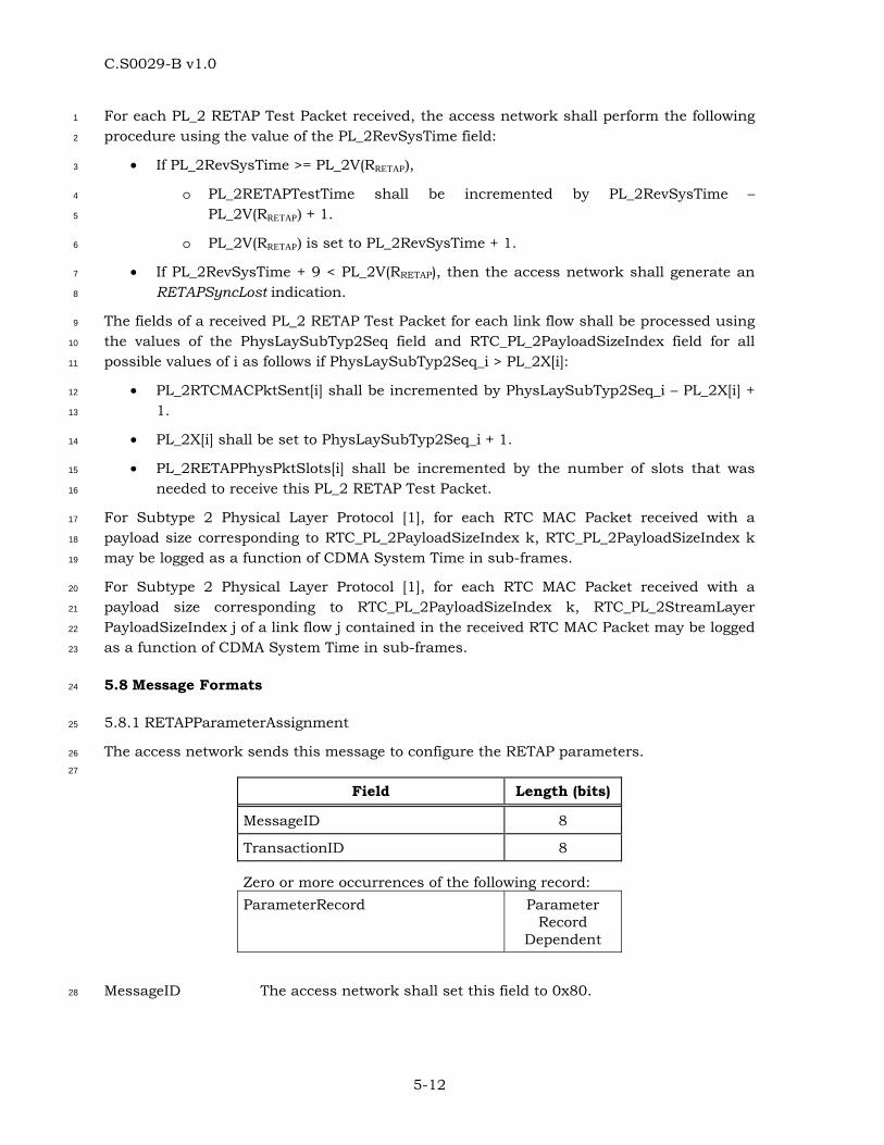
C.S0029-B v1.0
5-12
For each PL_2 RETAP Test Packet received, the access network shall perform the following 1
procedure using the value of the PL_2RevSysTime field: 2
• If PL_2RevSysTime >= PL_2V(RRETAP), 3
o PL_2RETAPTestTime shall be incremented by PL_2RevSysTime – 4
PL_2V(RRETAP) + 1. 5
o PL_2V(RRETAP) is set to PL_2RevSysTime + 1. 6
• If PL_2RevSysTime + 9 < PL_2V(RRETAP), then the access network shall generate an 7
RETAPSyncLost indication. 8
The fields of a received PL_2 RETAP Test Packet for each link flow shall be processed using 9
the values of the PhysLaySubTyp2Seq field and RTC_PL_2PayloadSizeIndex field for all 10
possible values of i as follows if PhysLaySubTyp2Seq_i > PL_2X[i]: 11
• PL_2RTCMACPktSent[i] shall be incremented by PhysLaySubTyp2Seq_i – PL_2X[i] + 12
1. 13
• PL_2X[i] shall be set to PhysLaySubTyp2Seq_i + 1. 14
• PL_2RETAPPhysPktSlots[i] shall be incremented by the number of slots that was 15
needed to receive this PL_2 RETAP Test Packet. 16
For Subtype 2 Physical Layer Protocol [1], for each RTC MAC Packet received with a 17
payload size corresponding to RTC_PL_2PayloadSizeIndex k, RTC_PL_2PayloadSizeIndex k 18
may be logged as a function of CDMA System Time in sub-frames. 19
For Subtype 2 Physical Layer Protocol [1], for each RTC MAC Packet received with a 20
payload size corresponding to RTC_PL_2PayloadSizeIndex k, RTC_PL_2StreamLayer 21
PayloadSizeIndex j of a link flow j contained in the received RTC MAC Packet may be logged 22
as a function of CDMA System Time in sub-frames. 23
5.8 Message Formats 24
5.8.1 RETAPParameterAssignment 25
The access network sends this message to configure the RETAP parameters. 26
27
Field Length (bits)
MessageID 8
TransactionID 8
Zero or more occurrences of the following record: ParameterRecord Parameter
Record Dependent
MessageID The access network shall set this field to 0x80. 28
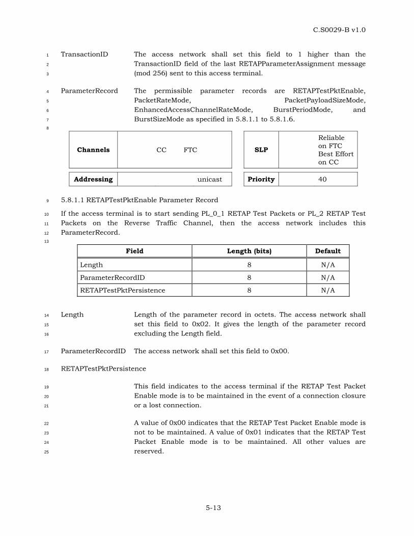
C.S0029-B v1.0
5-13
TransactionID The access network shall set this field to 1 higher than the 1
TransactionID field of the last RETAPParameterAssignment message 2
(mod 256) sent to this access terminal. 3
ParameterRecord The permissible parameter records are RETAPTestPktEnable, 4
PacketRateMode, PacketPayloadSizeMode, 5
EnhancedAccessChannelRateMode, BurstPeriodMode, and 6
BurstSizeMode as specified in 5.8.1.1 to 5.8.1.6. 7
8
Channels CC FTC SLP
Reliable on FTC Best Effort on CC
Addressing unicast Priority 40
5.8.1.1 RETAPTestPktEnable Parameter Record 9
If the access terminal is to start sending PL_0_1 RETAP Test Packets or PL_2 RETAP Test 10
Packets on the Reverse Traffic Channel, then the access network includes this 11
ParameterRecord. 12
13
Field Length (bits) Default
Length 8 N/A
ParameterRecordID 8 N/A
RETAPTestPktPersistence 8 N/A
Length Length of the parameter record in octets. The access network shall 14
set this field to 0x02. It gives the length of the parameter record 15
excluding the Length field. 16
ParameterRecordID The access network shall set this field to 0x00. 17
RETAPTestPktPersistence 18
This field indicates to the access terminal if the RETAP Test Packet 19
Enable mode is to be maintained in the event of a connection closure 20
or a lost connection. 21
A value of 0x00 indicates that the RETAP Test Packet Enable mode is 22
not to be maintained. A value of 0x01 indicates that the RETAP Test 23
Packet Enable mode is to be maintained. All other values are 24
reserved. 25

C.S0029-B v1.0
5-14
5.8.1.2 PacketRateMode Parameter Record 1
The access network includes this ParameterRecord if the Reverse Traffic Channel rate is to 2
be configured. Valid only for Subtype 0 and 1 Physical Layer Protocols [1]. 3
4
Field Length (bits) Default
Length 8 N/A
ParameterRecordID 8 N/A
MinRateIndex 8 0x00
MaxRateIndex 8 0x05
Length Length of the parameter record in octets. The access network shall 5
set this field to 0x03. It gives the length of the parameter record 6
excluding the Length field. 7
ParameterRecordID The access network shall set this field to 0x01. 8
MinRateIndex This field shall be set to the RTC_PL_0_1RateIndex (Table 5.8.1.2-1) 9
corresponding to the minimum RTC rate that the access terminal can 10
use to transmit the Subtype 0 and 1 Physical Layer Protocol RTC 11
MAC Packets. 12
MaxRateIndex This field shall be set to the RTC_PL_0_1RateIndex (Table 5.8.1.2-1) 13
corresponding to the maximum RTC rate that the access terminal 14
can use to transmit the Subtype 0 and 1 Physical Layer Protocol RTC 15
MAC Packets. 16
Table 5.8.1.2-1 Encoding of Subtype 0 and 1 Physical Layer Protocol RTC Rates 17
RTC_PL_0_1RateIndex RTC Rate
0 0 kbps
1 9.6 kbps
2 19.2 kbps
3 38.4 kbps
4 76.8 kbps
5 153.6 kbps
All other values Invalid
5.8.1.3 PacketPayloadSizeMode Parameter Record 18
The access network includes this ParameterRecord if the Reverse Traffic Channel payload 19
size is to be configured. Valid only for Subtype 2 Physical Layer Protocol [1]. 20
21
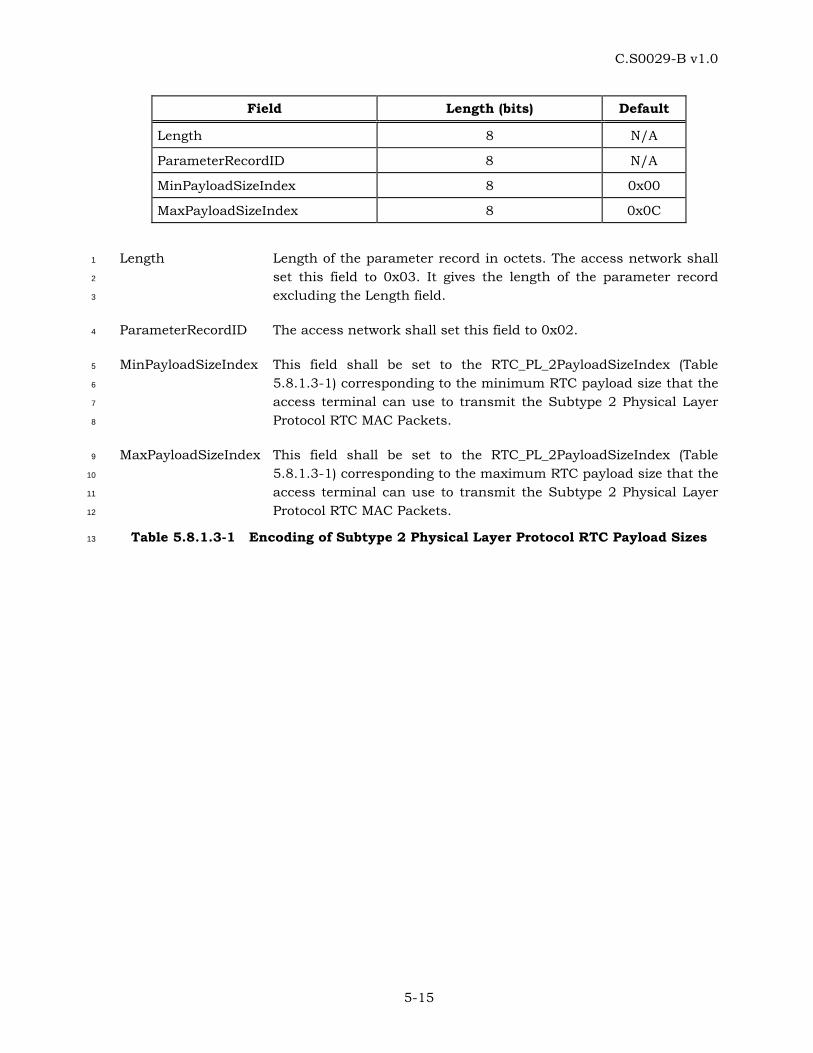
C.S0029-B v1.0
5-15
Field Length (bits) Default
Length 8 N/A
ParameterRecordID 8 N/A
MinPayloadSizeIndex 8 0x00
MaxPayloadSizeIndex 8 0x0C
Length Length of the parameter record in octets. The access network shall 1
set this field to 0x03. It gives the length of the parameter record 2
excluding the Length field. 3
ParameterRecordID The access network shall set this field to 0x02. 4
MinPayloadSizeIndex This field shall be set to the RTC_PL_2PayloadSizeIndex (Table 5
5.8.1.3-1) corresponding to the minimum RTC payload size that the 6
access terminal can use to transmit the Subtype 2 Physical Layer 7
Protocol RTC MAC Packets. 8
MaxPayloadSizeIndex This field shall be set to the RTC_PL_2PayloadSizeIndex (Table 9
5.8.1.3-1) corresponding to the maximum RTC payload size that the 10
access terminal can use to transmit the Subtype 2 Physical Layer 11
Protocol RTC MAC Packets. 12
Table 5.8.1.3-1 Encoding of Subtype 2 Physical Layer Protocol RTC Payload Sizes 13
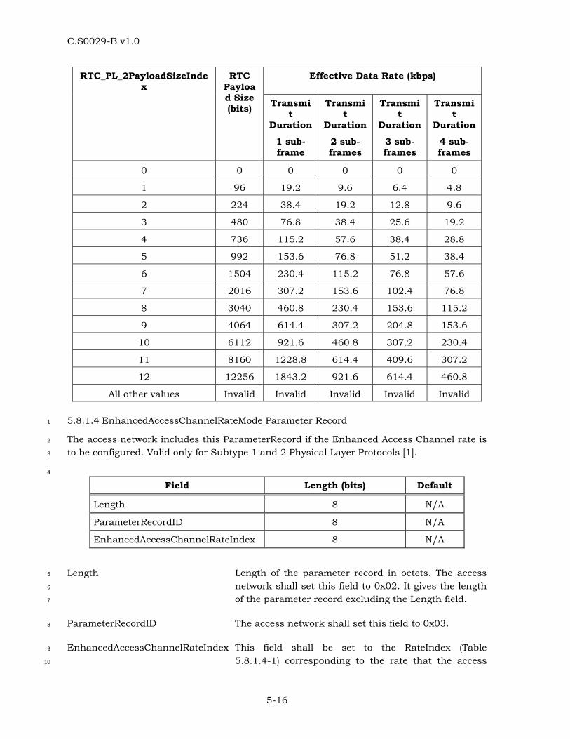
C.S0029-B v1.0
5-16
Effective Data Rate (kbps) RTC_PL_2PayloadSizeIndex
RTC Payload Size (bits) Transmi
t Duration
1 sub-frame
Transmit
Duration
2 sub-frames
Transmit
Duration
3 sub-frames
Transmit
Duration
4 sub-frames
0 0 0 0 0 0
1 96 19.2 9.6 6.4 4.8
2 224 38.4 19.2 12.8 9.6
3 480 76.8 38.4 25.6 19.2
4 736 115.2 57.6 38.4 28.8
5 992 153.6 76.8 51.2 38.4
6 1504 230.4 115.2 76.8 57.6
7 2016 307.2 153.6 102.4 76.8
8 3040 460.8 230.4 153.6 115.2
9 4064 614.4 307.2 204.8 153.6
10 6112 921.6 460.8 307.2 230.4
11 8160 1228.8 614.4 409.6 307.2
12 12256 1843.2 921.6 614.4 460.8
All other values Invalid Invalid Invalid Invalid Invalid
5.8.1.4 EnhancedAccessChannelRateMode Parameter Record 1
The access network includes this ParameterRecord if the Enhanced Access Channel rate is 2
to be configured. Valid only for Subtype 1 and 2 Physical Layer Protocols [1]. 3
4
Field Length (bits) Default
Length 8 N/A
ParameterRecordID 8 N/A
EnhancedAccessChannelRateIndex 8 N/A
Length Length of the parameter record in octets. The access 5
network shall set this field to 0x02. It gives the length 6
of the parameter record excluding the Length field. 7
ParameterRecordID The access network shall set this field to 0x03. 8
EnhancedAccessChannelRateIndex This field shall be set to the RateIndex (Table 9
5.8.1.4-1) corresponding to the rate that the access 10
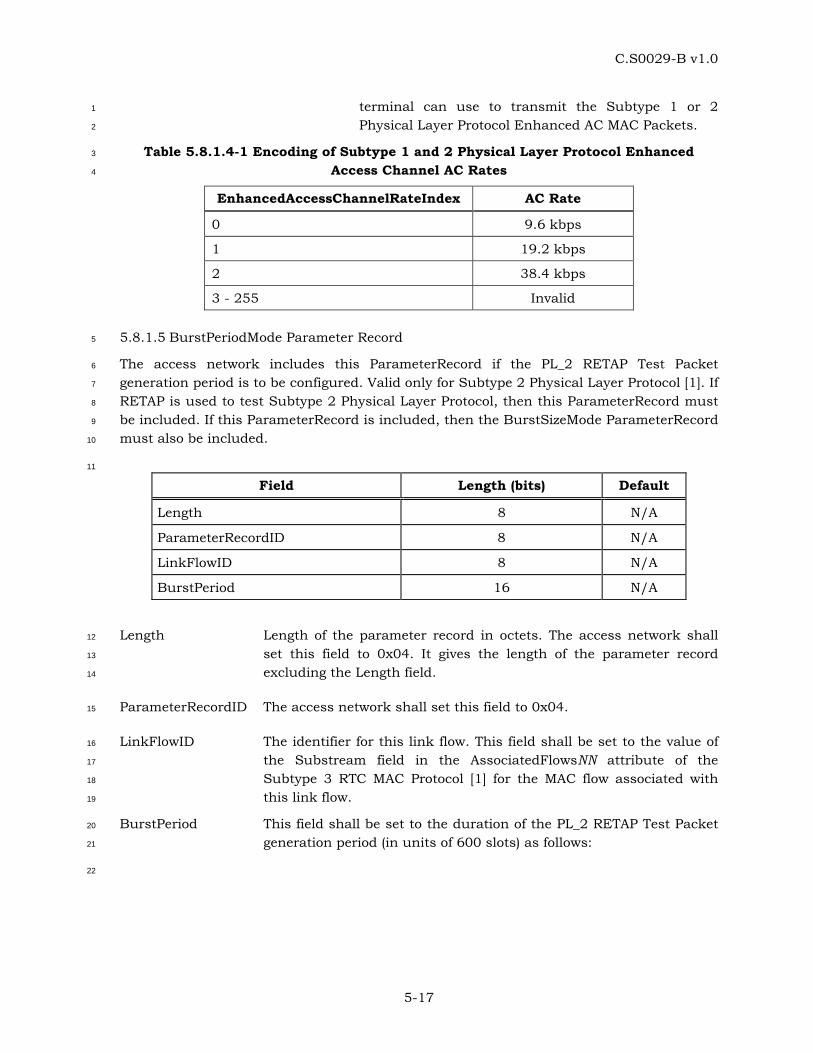
C.S0029-B v1.0
5-17
terminal can use to transmit the Subtype 1 or 2 1
Physical Layer Protocol Enhanced AC MAC Packets. 2
Table 5.8.1.4-1 Encoding of Subtype 1 and 2 Physical Layer Protocol Enhanced 3
Access Channel AC Rates 4
EnhancedAccessChannelRateIndex AC Rate
0 9.6 kbps
1 19.2 kbps
2 38.4 kbps
3 - 255 Invalid
5.8.1.5 BurstPeriodMode Parameter Record 5
The access network includes this ParameterRecord if the PL_2 RETAP Test Packet 6
generation period is to be configured. Valid only for Subtype 2 Physical Layer Protocol [1]. If 7
RETAP is used to test Subtype 2 Physical Layer Protocol, then this ParameterRecord must 8
be included. If this ParameterRecord is included, then the BurstSizeMode ParameterRecord 9
must also be included. 10
11
Field Length (bits) Default
Length 8 N/A
ParameterRecordID 8 N/A
LinkFlowID 8 N/A
BurstPeriod 16 N/A
Length Length of the parameter record in octets. The access network shall 12
set this field to 0x04. It gives the length of the parameter record 13
excluding the Length field. 14
ParameterRecordID The access network shall set this field to 0x04. 15
LinkFlowID The identifier for this link flow. This field shall be set to the value of 16
the Substream field in the AssociatedFlowsNN attribute of the 17
Subtype 3 RTC MAC Protocol [1] for the MAC flow associated with 18
this link flow. 19
BurstPeriod This field shall be set to the duration of the PL_2 RETAP Test Packet 20
generation period (in units of 600 slots) as follows: 21
22
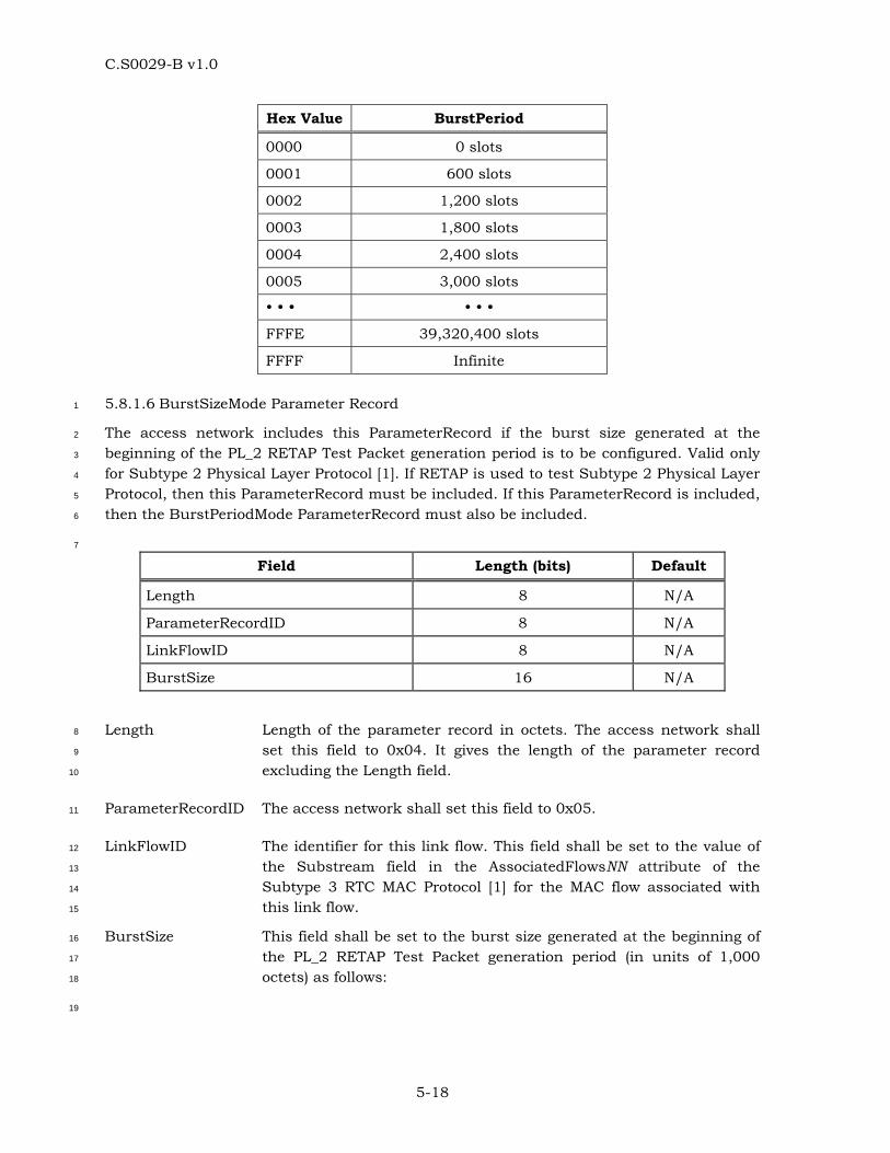
C.S0029-B v1.0
5-18
Hex Value BurstPeriod
0000 0 slots
0001 600 slots
0002 1,200 slots
0003 1,800 slots
0004 2,400 slots
0005 3,000 slots
FFFE 39,320,400 slots
FFFF Infinite
5.8.1.6 BurstSizeMode Parameter Record 1
The access network includes this ParameterRecord if the burst size generated at the 2
beginning of the PL_2 RETAP Test Packet generation period is to be configured. Valid only 3
for Subtype 2 Physical Layer Protocol [1]. If RETAP is used to test Subtype 2 Physical Layer 4
Protocol, then this ParameterRecord must be included. If this ParameterRecord is included, 5
then the BurstPeriodMode ParameterRecord must also be included. 6
7
Field Length (bits) Default
Length 8 N/A
ParameterRecordID 8 N/A
LinkFlowID 8 N/A
BurstSize 16 N/A
Length Length of the parameter record in octets. The access network shall 8
set this field to 0x04. It gives the length of the parameter record 9
excluding the Length field. 10
ParameterRecordID The access network shall set this field to 0x05. 11
LinkFlowID The identifier for this link flow. This field shall be set to the value of 12
the Substream field in the AssociatedFlowsNN attribute of the 13
Subtype 3 RTC MAC Protocol [1] for the MAC flow associated with 14
this link flow. 15
BurstSize This field shall be set to the burst size generated at the beginning of 16
the PL_2 RETAP Test Packet generation period (in units of 1,000 17
octets) as follows: 18
19
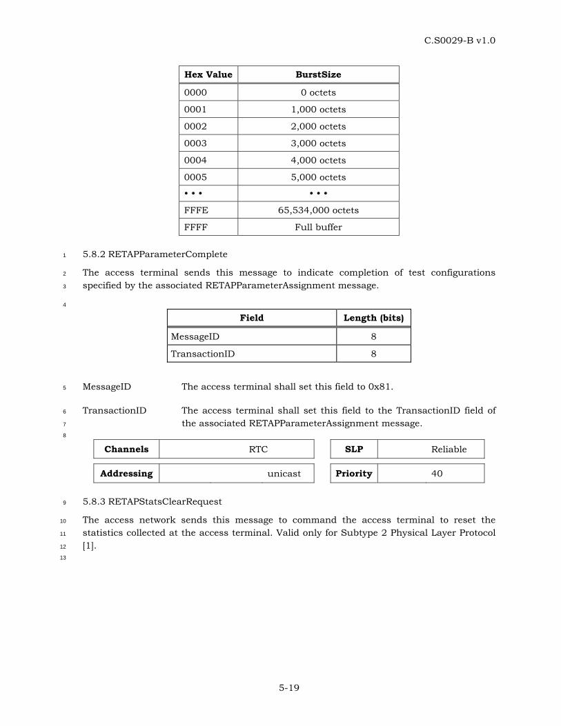
C.S0029-B v1.0
5-19
Hex Value BurstSize
0000 0 octets
0001 1,000 octets
0002 2,000 octets
0003 3,000 octets
0004 4,000 octets
0005 5,000 octets
FFFE 65,534,000 octets
FFFF Full buffer
5.8.2 RETAPParameterComplete 1
The access terminal sends this message to indicate completion of test configurations 2
specified by the associated RETAPParameterAssignment message. 3
4
Field Length (bits)
MessageID 8
TransactionID 8
MessageID The access terminal shall set this field to 0x81. 5
TransactionID The access terminal shall set this field to the TransactionID field of 6
the associated RETAPParameterAssignment message. 7
8
Channels RTC SLP Reliable
Addressing unicast Priority 40
5.8.3 RETAPStatsClearRequest 9
The access network sends this message to command the access terminal to reset the 10
statistics collected at the access terminal. Valid only for Subtype 2 Physical Layer Protocol 11
[1]. 12
13
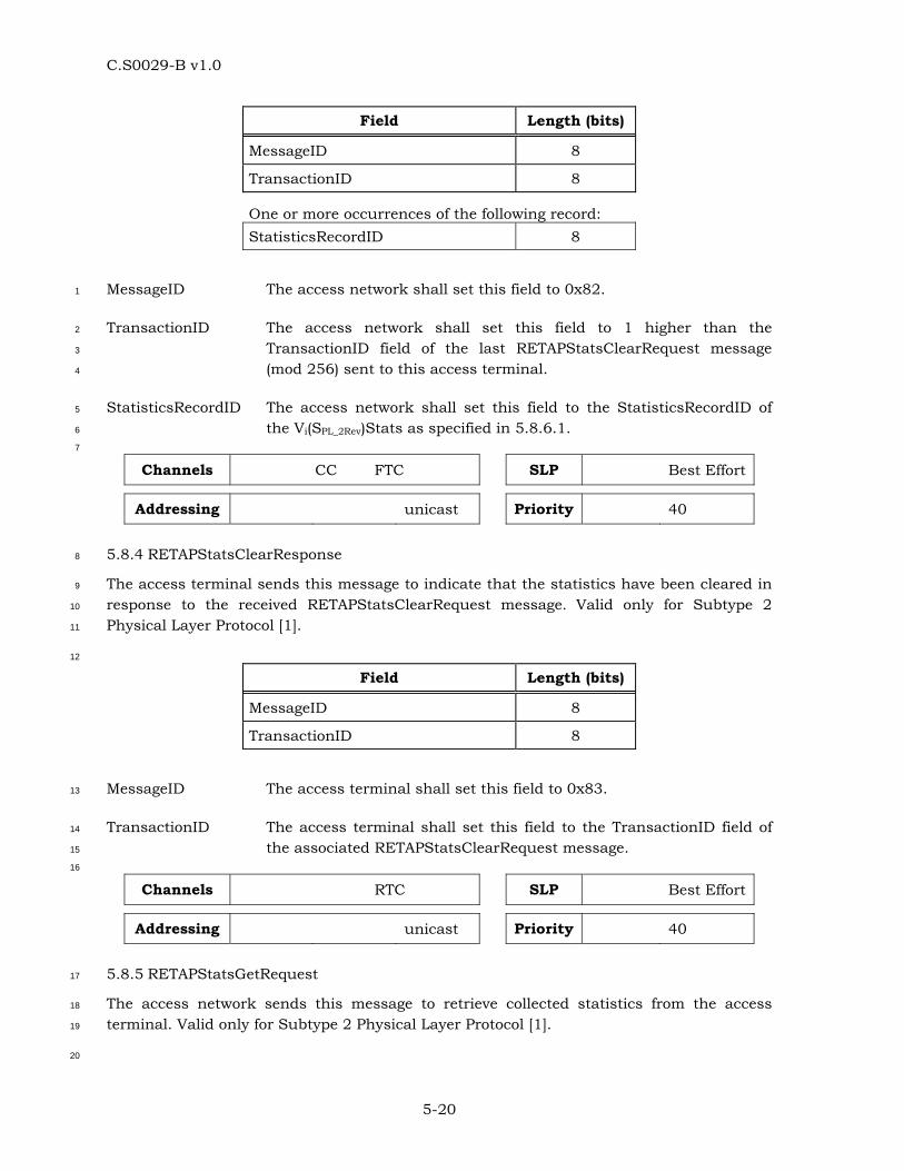
C.S0029-B v1.0
5-20
Field Length (bits)
MessageID 8
TransactionID 8
One or more occurrences of the following record: StatisticsRecordID 8
MessageID The access network shall set this field to 0x82. 1
TransactionID The access network shall set this field to 1 higher than the 2
TransactionID field of the last RETAPStatsClearRequest message 3
(mod 256) sent to this access terminal. 4
StatisticsRecordID The access network shall set this field to the StatisticsRecordID of 5
the Vi(SPL_2Rev)Stats as specified in 5.8.6.1. 6
7
Channels CC FTC SLP Best Effort
Addressing unicast Priority 40
5.8.4 RETAPStatsClearResponse 8
The access terminal sends this message to indicate that the statistics have been cleared in 9
response to the received RETAPStatsClearRequest message. Valid only for Subtype 2 10
Physical Layer Protocol [1]. 11
12
Field Length (bits)
MessageID 8
TransactionID 8
MessageID The access terminal shall set this field to 0x83. 13
TransactionID The access terminal shall set this field to the TransactionID field of 14
the associated RETAPStatsClearRequest message. 15
16
Channels RTC SLP Best Effort
Addressing unicast Priority 40
5.8.5 RETAPStatsGetRequest 17
The access network sends this message to retrieve collected statistics from the access 18
terminal. Valid only for Subtype 2 Physical Layer Protocol [1]. 19
20
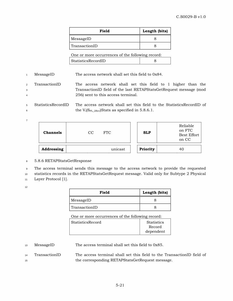
C.S0029-B v1.0
5-21
Field Length (bits)
MessageID 8
TransactionID 8
One or more occurrences of the following record: StatisticsRecordID 8
MessageID The access network shall set this field to 0x84. 1
TransactionID The access network shall set this field to 1 higher than the 2
TransactionID field of the last RETAPStatsGetRequest message (mod 3
256) sent to this access terminal. 4
StatisticsRecordID The access network shall set this field to the StatisticsRecordID of 5
the Vi(SPL_2Rev)Stats as specified in 5.8.6.1. 6
7
Channels CC FTC SLP
Reliable on FTC Best Effort on CC
Addressing unicast Priority 40
5.8.6 RETAPStatsGetResponse 8
The access terminal sends this message to the access network to provide the requested 9
statistics records in the RETAPStatsGetRequest message. Valid only for Subtype 2 Physical 10
Layer Protocol [1]. 11
12
Field Length (bits)
MessageID 8
TransactionID 8
One or more occurrences of the following record: StatisticsRecord Statistics
Record dependent
MessageID The access terminal shall set this field to 0x85. 13
TransactionID The access terminal shall set this field to the TransactionID field of 14
the corresponding RETAPStatsGetRequest message. 15
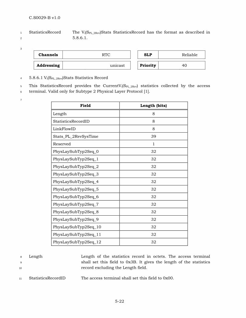
C.S0029-B v1.0
5-22
StatisticsRecord The Vi(SPL_2Rev)Stats StatisticsRecord has the format as described in 1
5.8.6.1. 2
3
Channels RTC SLP Reliable
Addressing unicast Priority 40
5.8.6.1 Vi(SPL_2Rev)Stats Statistics Record 4
This StatisticsRecord provides the CurrentVi(SPL_2Rev) statistics collected by the access 5
terminal. Valid only for Subtype 2 Physical Layer Protocol [1]. 6
7
Field Length (bits)
Length 8
StatisticsRecordID 8
LinkFlowID 8
Stats_PL_2RevSysTime 39
Reserved 1
PhysLaySubTyp2Seq_0 32
PhysLaySubTyp2Seq_1 32
PhysLaySubTyp2Seq_2 32
PhysLaySubTyp2Seq_3 32
PhysLaySubTyp2Seq_4 32
PhysLaySubTyp2Seq_5 32
PhysLaySubTyp2Seq_6 32
PhysLaySubTyp2Seq_7 32
PhysLaySubTyp2Seq_8 32
PhysLaySubTyp2Seq_9 32
PhysLaySubTyp2Seq_10 32
PhysLaySubTyp2Seq_11 32
PhysLaySubTyp2Seq_12 32
Length Length of the statistics record in octets. The access terminal 8
shall set this field to 0x3B. It gives the length of the statistics 9
record excluding the Length field. 10
StatisticsRecordID The access terminal shall set this field to 0x00. 11
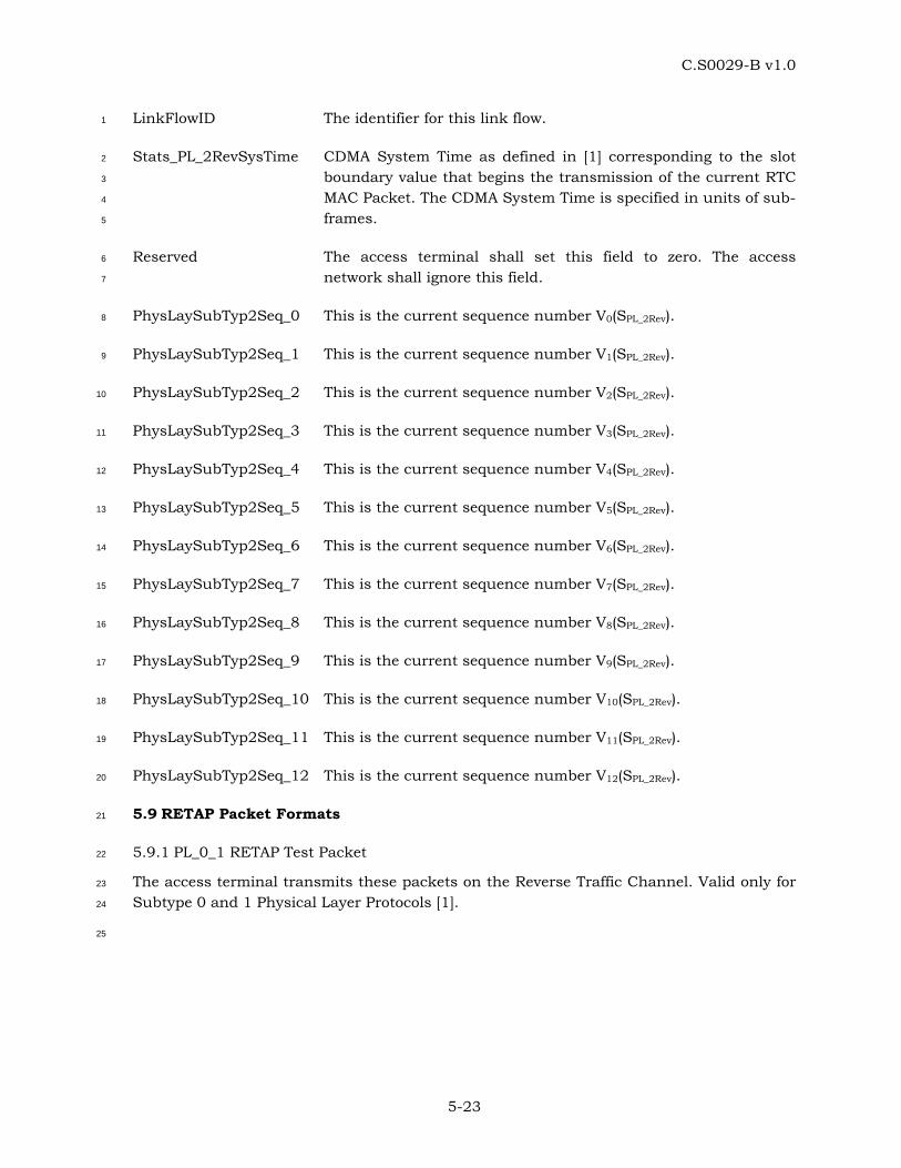
C.S0029-B v1.0
5-23
LinkFlowID The identifier for this link flow. 1
Stats_PL_2RevSysTime CDMA System Time as defined in [1] corresponding to the slot 2
boundary value that begins the transmission of the current RTC 3
MAC Packet. The CDMA System Time is specified in units of sub-4
frames. 5
Reserved The access terminal shall set this field to zero. The access 6
network shall ignore this field. 7
PhysLaySubTyp2Seq_0 This is the current sequence number V0(SPL_2Rev). 8
PhysLaySubTyp2Seq_1 This is the current sequence number V1(SPL_2Rev). 9
PhysLaySubTyp2Seq_2 This is the current sequence number V2(SPL_2Rev). 10
PhysLaySubTyp2Seq_3 This is the current sequence number V3(SPL_2Rev). 11
PhysLaySubTyp2Seq_4 This is the current sequence number V4(SPL_2Rev). 12
PhysLaySubTyp2Seq_5 This is the current sequence number V5(SPL_2Rev). 13
PhysLaySubTyp2Seq_6 This is the current sequence number V6(SPL_2Rev). 14
PhysLaySubTyp2Seq_7 This is the current sequence number V7(SPL_2Rev). 15
PhysLaySubTyp2Seq_8 This is the current sequence number V8(SPL_2Rev). 16
PhysLaySubTyp2Seq_9 This is the current sequence number V9(SPL_2Rev). 17
PhysLaySubTyp2Seq_10 This is the current sequence number V10(SPL_2Rev). 18
PhysLaySubTyp2Seq_11 This is the current sequence number V11(SPL_2Rev). 19
PhysLaySubTyp2Seq_12 This is the current sequence number V12(SPL_2Rev). 20
5.9 RETAP Packet Formats 21
5.9.1 PL_0_1 RETAP Test Packet 22
The access terminal transmits these packets on the Reverse Traffic Channel. Valid only for 23
Subtype 0 and 1 Physical Layer Protocols [1]. 24
25
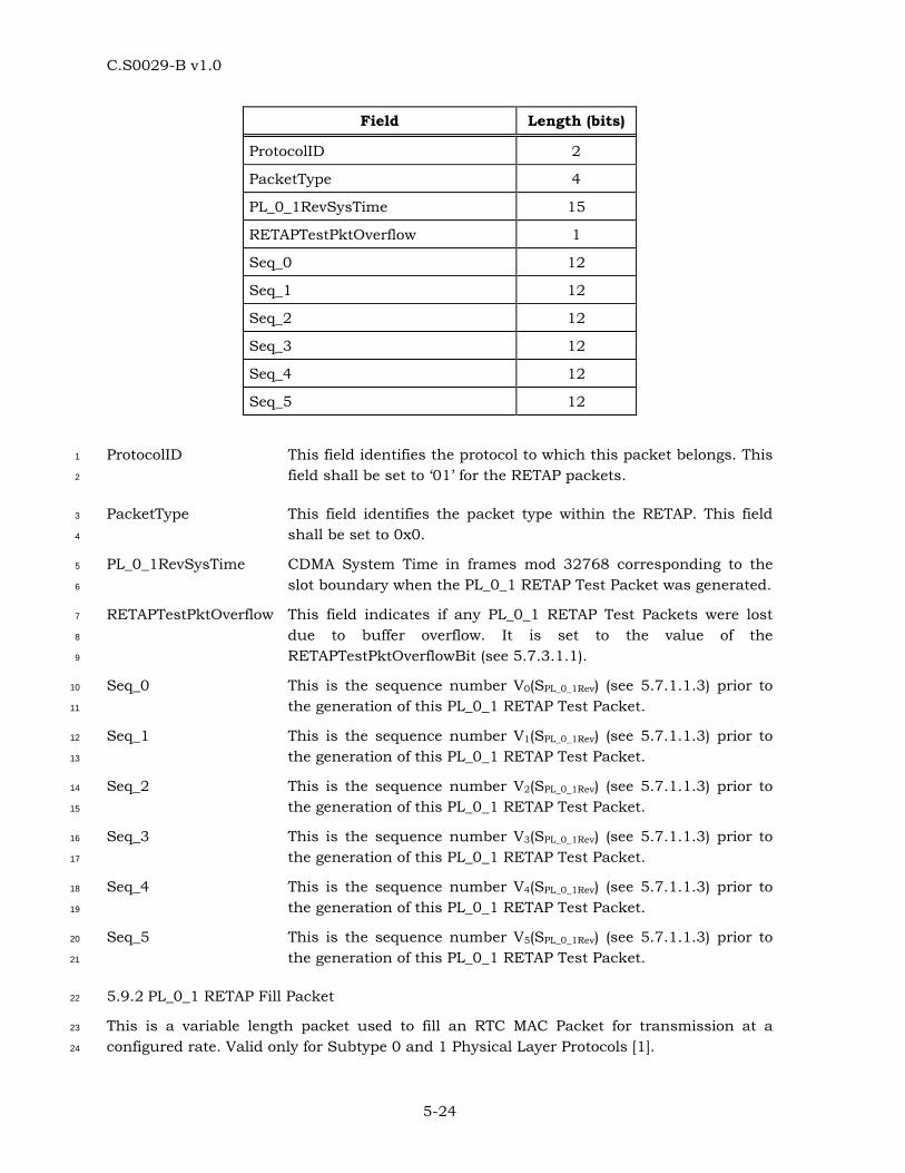
C.S0029-B v1.0
5-24
Field Length (bits)
ProtocolID 2
PacketType 4
PL_0_1RevSysTime 15
RETAPTestPktOverflow 1
Seq_0 12
Seq_1 12
Seq_2 12
Seq_3 12
Seq_4 12
Seq_5 12
ProtocolID This field identifies the protocol to which this packet belongs. This 1
field shall be set to ‘01’ for the RETAP packets. 2
PacketType This field identifies the packet type within the RETAP. This field 3
shall be set to 0x0. 4
PL_0_1RevSysTime CDMA System Time in frames mod 32768 corresponding to the 5
slot boundary when the PL_0_1 RETAP Test Packet was generated. 6
RETAPTestPktOverflow This field indicates if any PL_0_1 RETAP Test Packets were lost 7
due to buffer overflow. It is set to the value of the 8
RETAPTestPktOverflowBit (see 5.7.3.1.1). 9
Seq_0 This is the sequence number V0(SPL_0_1Rev) (see 5.7.1.1.3) prior to 10
the generation of this PL_0_1 RETAP Test Packet. 11
Seq_1 This is the sequence number V1(SPL_0_1Rev) (see 5.7.1.1.3) prior to 12
the generation of this PL_0_1 RETAP Test Packet. 13
Seq_2 This is the sequence number V2(SPL_0_1Rev) (see 5.7.1.1.3) prior to 14
the generation of this PL_0_1 RETAP Test Packet. 15
Seq_3 This is the sequence number V3(SPL_0_1Rev) (see 5.7.1.1.3) prior to 16
the generation of this PL_0_1 RETAP Test Packet. 17
Seq_4 This is the sequence number V4(SPL_0_1Rev) (see 5.7.1.1.3) prior to 18
the generation of this PL_0_1 RETAP Test Packet. 19
Seq_5 This is the sequence number V5(SPL_0_1Rev) (see 5.7.1.1.3) prior to 20
the generation of this PL_0_1 RETAP Test Packet. 21
5.9.2 PL_0_1 RETAP Fill Packet 22
This is a variable length packet used to fill an RTC MAC Packet for transmission at a 23
configured rate. Valid only for Subtype 0 and 1 Physical Layer Protocols [1]. 24
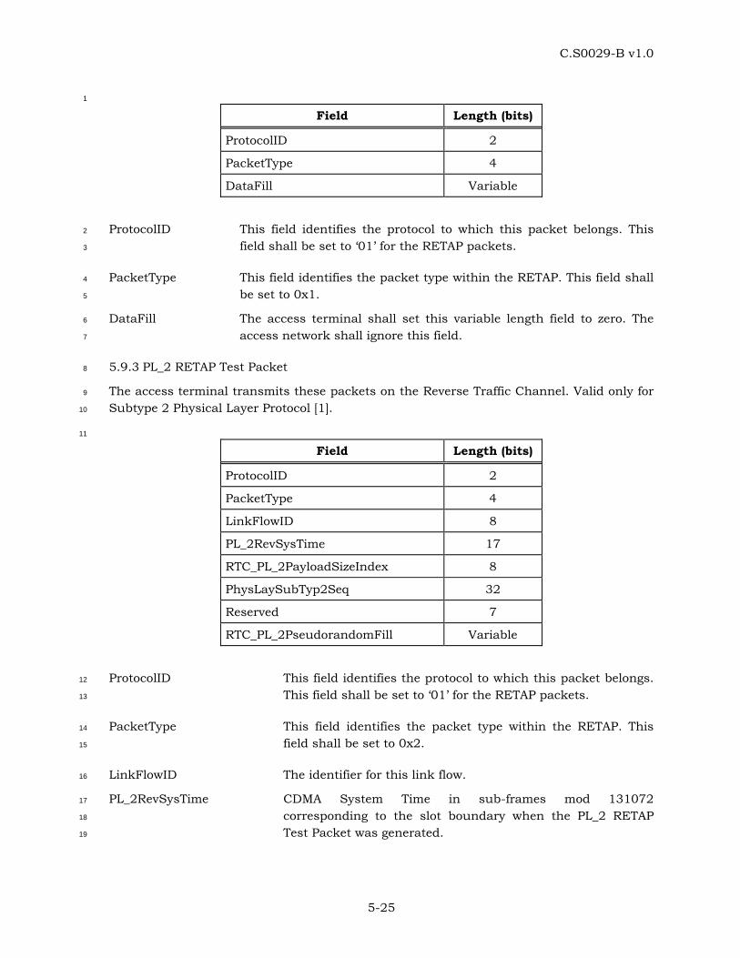
C.S0029-B v1.0
5-25
1
Field Length (bits)
ProtocolID 2
PacketType 4
DataFill Variable
ProtocolID This field identifies the protocol to which this packet belongs. This 2
field shall be set to ‘01’ for the RETAP packets. 3
PacketType This field identifies the packet type within the RETAP. This field shall 4
be set to 0x1. 5
DataFill The access terminal shall set this variable length field to zero. The 6
access network shall ignore this field. 7
5.9.3 PL_2 RETAP Test Packet 8
The access terminal transmits these packets on the Reverse Traffic Channel. Valid only for 9
Subtype 2 Physical Layer Protocol [1]. 10
11
Field Length (bits)
ProtocolID 2
PacketType 4
LinkFlowID 8
PL_2RevSysTime 17
RTC_PL_2PayloadSizeIndex 8
PhysLaySubTyp2Seq 32
Reserved 7
RTC_PL_2PseudorandomFill Variable
ProtocolID This field identifies the protocol to which this packet belongs. 12
This field shall be set to ‘01’ for the RETAP packets. 13
PacketType This field identifies the packet type within the RETAP. This 14
field shall be set to 0x2. 15
LinkFlowID The identifier for this link flow. 16
PL_2RevSysTime CDMA System Time in sub-frames mod 131072 17
corresponding to the slot boundary when the PL_2 RETAP 18
Test Packet was generated. 19
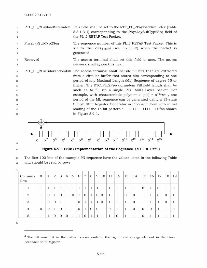
C.S0029-B v1.0
5-26
RTC_PL_2PayloadSizeIndex This field shall be set to the RTC_PL_2PayloadSizeIndex (Table 1
5.8.1.3-1) corresponding to the PhysLaySubTyp2Seq field of 2
the PL_2 RETAP Test Packet. 3
PhysLaySubTyp2Seq The sequence number of this PL_2 RETAP Test Packet. This is 4
set to the Vi(SPL_2Rev) (see 5.7.1.1.3) when the packet is 5
generated. 6
Reserved The access terminal shall set this field to zero. The access 7
network shall ignore this field. 8
RTC_PL_2PseudorandomFill The access terminal shall include fill bits that are extracted 9
from a circular buffer that stores bits corresponding to one 10
period of any Maximal Length (ML) Sequence of degree 15 or 11
higher. The RTC_PL_2Pseudorandom Fill field length shall be 12
such as to fill up a single RTC MAC Layer packet. For 13
example, with characteristic polynomial p(x) = x15+x+1, one 14
period of the ML sequence can be generated using a 15-state 15
Simple Shift Register Generator in Fibonacci form with initial 16
loading of the 15 bit pattern ‘1111 1111 1111 111’4as shown 17
in Figure 5.9-1. 18
+
x x2 x3 x4 x5 x6 x7 x8 x9 x10 x11 x12 x13 x14 x15 19
Figure 5.9-1 SSRG Implementation of the Sequence 1/(1 + x + x15 ) 20
The first 100 bits of the example PN sequence have the values listed in the following Table 21
and should be read by rows. 22
23
Column\ Row
0 1 2 3 4 5 6 7 8 9 10 11 12 13 14 15 16 17 18 19
1 1 1 1 1 1 1 1 1 1 1 1 1 1 1 1 0 1 0 1 0
2 1 0 1 0 1 0 1 0 1 0 0 1 1 0 0 1 1 0 0 1
3 1 0 0 1 1 1 0 1 1 1 0 1 1 1 0 1 1 1 0 1
4 0 0 1 0 1 1 0 1 0 0 1 0 1 1 0 0 0 1 1 0
5 1 1 0 0 0 1 1 0 1 1 1 1 0 1 1 0 1 1 1 1
24
4 The left most bit in the pattern corresponds to the right most storage element in the Linear Feedback Shift Register
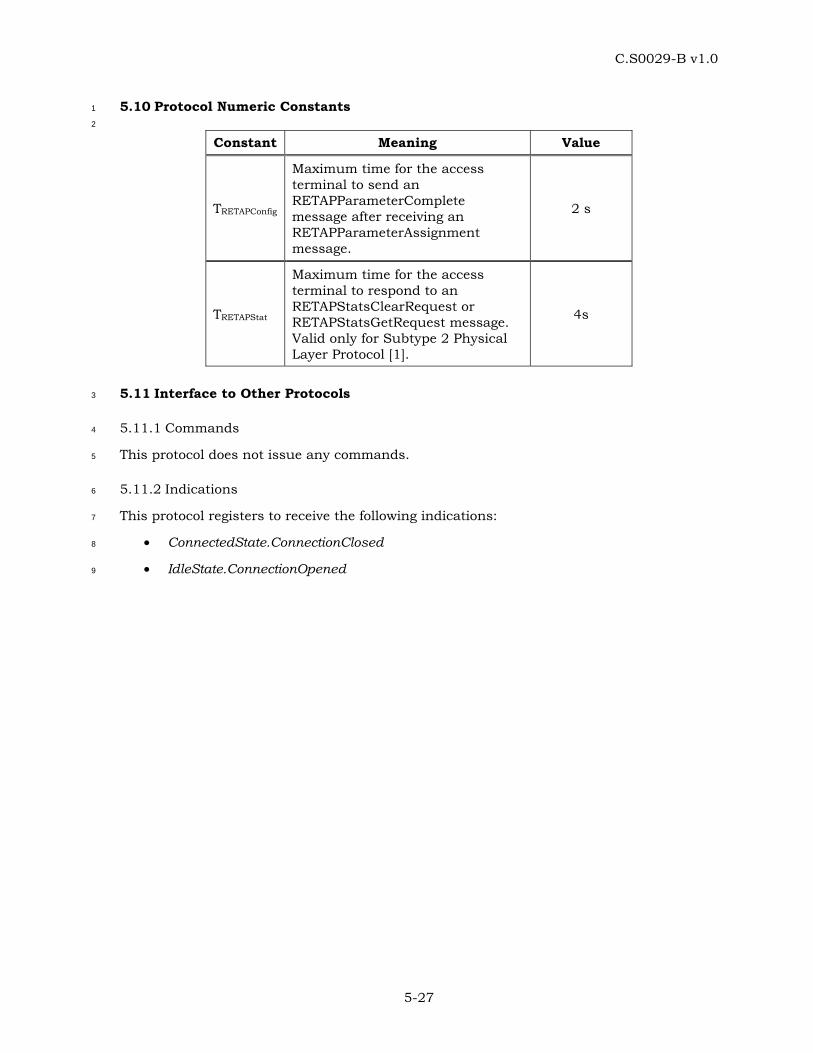
C.S0029-B v1.0
5-27
5.10 Protocol Numeric Constants 1
2
Constant Meaning Value
TRETAPConfig
Maximum time for the access terminal to send an RETAPParameterComplete message after receiving an RETAPParameterAssignment message.
2 s
TRETAPStat
Maximum time for the access terminal to respond to an RETAPStatsClearRequest or RETAPStatsGetRequest message. Valid only for Subtype 2 Physical Layer Protocol [1].
4s
5.11 Interface to Other Protocols 3
5.11.1 Commands 4
This protocol does not issue any commands. 5
5.11.2 Indications 6
This protocol registers to receive the following indications: 7
• ConnectedState.ConnectionClosed 8
• IdleState.ConnectionOpened 9

C.S0029-B v1.0
5-28
No text. 1
C.S0029-B v1.0
6-1
6 FORWARD MULTICARRIER TEST APPLICATION PROTOCOL (FMCTAP) 1
SPECIFICATION 2
6.1 Overview 3
The Forward Multicarrier Test Application Protocol (FMCTAP) provides the procedures and 4
messages used by the access terminal and the access network to: 5
• Control FMCTAP test configurations at both the access terminal and the access 6
network. 7
• Generate PL_0_1_2_3 FMCTAP Test Packets at the access network for transmission 8
on the Forward Traffic Channel and process the received packets at the access 9
terminal. 10
• Generate and transmit information about the received PL_0_1_2_3 FMCTAP Test 11
Packets at the access terminal through PL_0_1 FMCTAP Loop Back Packets, PL_2 12
FMCTAP Loop Back Packets and PL_3 FMCTAP Loop Back Packets. PL_3 FMCTAP 13
Loop Back Packets associated with each sub-active set are to be transmitted on the 14
associated Reverse Link CDMA channel where the association is specified in the 15
TrafficChannelAssignment Message, i.e., the Reverse Link CDMA channel that 16
carries DRC, DSC and ACK channels for the sub-active set. 17
• Transmit configured ACK Channel bits, DRC values and DRC covers specified for 18
each sub-active set. 19
• Transmit ACK Channel using configured modulation type. Valid only for Subtype 2 20
and 3 Physical Layer Protocol [1]. 21
• Collect statistics on the changes in the serving sector as seen at the access terminal 22
in the Idle State and the Connected State. 23
• Collect statistics on the number of successfully received first Synchronous Control 24
Channel packets. 25
Throughout this section, the notation ‘PL_0_1_2_3’ refers to Subtype 0, 1, 2 or 3 Physical 26
Layer Protocol [1] applicability. The notation ‘PL_0_1’ refers to Subtype 0 or 1 Physical 27
Layer Protocol [1] applicability. The notation ‘PL_2’ refers to Subtype 2 Physical Layer 28
Protocol [1] applicability. The notation ‘PL_3’ refers to Subtype 3 Physical Layer Protocol [1] 29
applicability. 30
6.2 Data Encapsulation 31
In the transmit direction, the FMCTAP generates test packets and forwards them to the 32
stream layer. 33
In the receive direction the FMCTAP receives test packets from the stream layer and 34
processes them. 35
Figure 6.2-1 illustrates the relationship between the FMCTAP packets and the Stream 36
Layer payload. 37

C.S0029-B v1.0
6-2
StreamLayer
payload
FMCTAP packet
1
Figure 6.2-1 FMCTAP Packet Encapsulation 2
6.3 Primitives and Public Data 3
6.3.1 Commands 4
This protocol does not define any commands. 5
6.3.2 Indications 6
This protocol returns the following indications: 7
• LoopbackSyncLost 8
6.3.3 Public Data 9
Subtype for this application. 10
6.4 Basic Protocol Numbers 11
FMCTAP is a protocol associated with the Multicarrier Test Application. This protocol shall 12
use the application subtype value for the Multicarrier Test Application as specified in 1.5. 13
6.5 Protocol Data Unit 14
The transmission unit of this protocol is an FMCTAP packet. The FMCTAP packet size is 15
determined by the lower layers that are negotiated during session configuration. 16
The FMCTAP also uses signaling messages for controlling and configuring the access 17
terminal and the access network for conducting tests on the Forward Traffic Channel. 18
When FMCTAP sends these messages it shall use the Signaling Application [1]. 19
6.6 Test Statistics 20
6.6.1 Access Terminal Requirements 21
The access terminal shall maintain the following statistics: 22
• IdleASPChange: This counts the number of changes in the Active Set Pilot in the 23
Idle State. The Active Set Pilot (ASP) is the pilot associated with the Control Channel 24
the access terminal is currently monitoring. A pilot is characterized by a PN offset 25
and a CDMA Channel. 26
C.S0029-B v1.0
6-3
• IdleTime: Elapsed time in slots in the Idle State since the start of statistics 1
collection. 2
• ConnectedSSChange: This counts the number of changes in the Serving Sector (SS) 3
in the connected State with PL_0_1_2. The serving sector is the one the DRC is 4
pointed at. When the DRC is re-pointed from one sector to another, the DRC cover 5
transitions through a NULL cover. For example, if the DRC cover changes from a 6
sector cover A through NULL cover to a sector cover B (with A not equal to B), it is 7
counted as one SS change. On the other hand, if DRC cover changes from a sector 8
cover A through NULL cover to a sector cover A again, it is not counted as an SS 9
change. 10
• ConnectedSSChangeMC[j]: This counts the number of changes in the Serving Sector 11
(SS) in the connected State for sub-active set index j with PL_3. The serving sector is 12
the one the DRC is pointed at. When the DRC is re-pointed from one sector to 13
another, the DRC cover transitions through a NULL cover. For example, if the DRC 14
cover changes from a sector cover A through NULL cover to a sector cover B (with A 15
not equal to B), it is counted as one SS change. On the other hand, if DRC cover 16
changes from a sector cover A through NULL cover to a sector cover A again, it is 17
not counted as an SS change. 18
• ConnectedTime: Elapsed time in slots in the Connected State since the start of 19
statistics collection. 20
• FirstSyncCCPkt: The number of successfully received first CC MAC Layer packets in 21
synchronous capsules. 22
• CCTime: Elapsed time in Control Channel Cycles since the start of statistics 23
collection. 24
6.6.2 Access Network Requirements 25
The access network may maintain the following statistics for each sector when the Loop 26
Back mode is enabled: 27
• PL_0_1_2_3FMCTAPTestPktSent: This counts the number of PL_0_1_2_3 FMCTAP 28
Test Packets sent by the access network on the Forward Traffic Channel. 29
• PL_0_1_2_3FMCTAPTestPktRecd: This counts the number of PL_0_1_2_3 FMCTAP 30
Test Packets that were received by the access terminal on the Forward Traffic 31
Channel. 32
• PL_0_1FMCTAPMACPktRecd: This counts the number of Forward Traffic Channel 33
MAC layer packets that were received by the access terminal, in the Physical Layer 34
packets containing the PL_0_1_2_3 FMCTAP Test Packets. 35
• PL_2FMCTAPMACPktRecd[i]: Array whose (i+1)th element contains the number of 36
Forward Traffic Channel MAC layer packets that were received by the access 37
terminal, in the Physical Layer packets containing the PL_0_1_2_3 FMCTAP Test 38
Packets, at a payload size corresponding to the FTC_PL_2PayloadSizeIndex i as per 39
6.9.3 40
C.S0029-B v1.0
6-4
• PL_3FMCTAPMACPktRecd[i,j]: Array whose (i+1)th row and (j+1)th column contains 1
the number of Forward Traffic Channel MAC layer packets that were received by the 2
access terminal, in the Physical Layer packets containing the PL_0_1_2_3 FMCTAP 3
Test Packets, at a payload size corresponding to the FTC_PL_3PayloadSizeIndex i as 4
per 6.9.4 and sub-active set index j. 5
• PL_0_1_2_3FMCTAPTestTime: This counts FMCTAP test duration in frames [1]. 6
• PL_0_1FMCTAPPhysPktSlots: This counts the number of slots over which the 7
Physical Layer packets containing the PL_0_1_2_3 FMCTAP Test Packets were 8
received by the access terminal. 9
• PL_2FMCTAPPhysPktSlots[i]: Array whose (i+1)th element contains the number of 10
slots over which the Physical Layer packets containing the PL_0_1_2_3 FMCTAP 11
Test Packets were received by the access terminal corresponding to the 12
FTC_PL_2PayloadSizeIndex i as per 6.9.3. 13
• PL_3FMCTAPPhysPktSlots[i,j]: Array whose (i+1)th row and (j+1)th column contains 14
the number of slots over which the Physical Layer packets containing the 15
PL_0_1_2_3 FMCTAP Test Packets were received by the access terminal 16
corresponding to the FTC_PL_3PayloadSizeIndex i as per 6.9.4 and sub-active set 17
index j. 18
The access network may also maintain the following statistics for the overall test when the 19
Loop Back mode is enabled: 20
• PL_0_1FMCTAPLBPktSent: This counts the number of PL_0_1 FMCTAP Loop Back 21
Packets that were sent by the access terminal on the Reverse Traffic Channel. 22
• PL_0_1FMCTAPLBPktRecd: This counts the number of PL_0_1 FMCTAP Loop Back 23
Packets that were received by the access network on the Reverse Traffic Channel. 24
• PL_2FMCTAPLBPktSent: This counts the number of PL_2 FMCTAP Loop Back 25
Packets that were sent by the access terminal on the Reverse Traffic Channel. 26
• PL_2FMCTAPLBPktRecd: This counts the number of PL_2 FMCTAP Loop Back 27
Packets that were received by the access network on the Reverse Traffic Channel. 28
• PL_3FMCTAPLBPktSent[j]: This counts the number of PL_3 FMCTAP Loop Back 29
Packets that were sent by the access terminal on the Reverse Traffic Channel on 30
sub-active set index j. 31
• PL_3FMCTAPLBPktRecd[j]: This counts the number of PL_3 FMCTAP Loop Back 32
Packets that were received by the access network on the Reverse Traffic Channel on 33
sub-active set index j. 34
6.7 Procedures 35
FMCTAP is specified by the following procedures, which control and configure different 36
aspects of the Forward Traffic Channel tests. 37
• Test Parameter Configuration: Procedures and messages for configuring parameters 38
for different tests. 39

C.S0029-B v1.0
6-5
• Access Terminal Statistics Collection and Retrieval: Procedures and messages for 1
resetting the statistics being collected at the access terminal and for retrieving 2
them. 3
• PL_0_1_2_3 FMCTAP Test Packet Transmission and Reception: Procedures for 4
sending and receiving PL_0_1_2_3 FMCTAP Test Packets on the Forward Traffic 5
Channel. 6
• PL_0_1 FMCTAP Loop Back Packet Transmission and Reception: Procedures for 7
sending and receiving PL_0_1 FMCTAP Loop Back Packets on the Reverse Traffic 8
Channel. 9
• PL_2 FMCTAP Loop Back Packet Transmission and Reception: Procedures for 10
sending and receiving PL_2 FMCTAP Loop Back Packets on the Reverse Traffic 11
Channel. 12
• PL_3 FMCTAP Loop Back Packet Transmission and Reception: Procedures for 13
sending and receiving PL_3 FMCTAP Loop Back Packets on the Reverse Traffic 14
Channel. 15
• DRC Channel Transmission: Procedures for sending fixed DRC values and DRC 16
covers on the DRC channel. 17
• ACK Channel Transmission: Procedures for sending fixed ACK Channel bits on the 18
ACK Channel. Also, for Subtype 2 and 3 Physical Layer Protocol [1], procedures for 19
sending ACK Channel using a fixed modulation type. 20
• Sub-active set management: Procedures for keeping track of sub-active set indices 21
reported from TrafficChannelAssignment Message. Valid for Physical Layer Subtype 22
3 only. 23
6.7.1 Test Parameter Configuration 24
6.7.1.1 Access Terminal Requirements 25
When the protocol is instantiated, the access terminal shall execute the configuration 26
initialization procedure in 6.7.1.1.1. 27
When the protocol receives a ConnectedState.ConnectionClosed [1] indication, the access 28
terminal shall execute the configuration initialization procedure in 6.7.1.1.2. 29
If the access terminal receives an FMCTAPParameterAssignment message, it shall do the 30
following steps in sequence: 31
• Execute the configuration initialization procedure in 6.7.1.1.1. 32
• If the message includes a DRCValueFixedMode parameter record, the DRC Value 33
Fixed mode is enabled and the received DRCValue field is stored. If the message 34
includes a DRCValueFixedModeMC parameter record, the DRC Value Fixed mode 35
for multicarrier is enabled and the received DRCValue field is stored per sub-active 36
set. 37
• If the message includes a DRCCoverFixedMode parameter record, the DRC Cover 38
Fixed mode is enabled and the received DRCCover field is stored. If the message 39

C.S0029-B v1.0
6-6
includes a DRCCoverFixedModeMC parameter record, the DRC Cover Fixed mode 1
for multicarrier is enabled and the received DRCCover field is stored per sub-active 2
set. 3
• If the message includes an ACKChannelBitFixedMode parameter record, the ACK 4
Channel Bit Fixed mode is enabled and the received ACKChannelBit field is stored. 5
If the message includes an ACKChannelBitFixedModeMC parameter record, the 6
ACK Channel Bit Fixed mode for multicarrier is enabled and the received 7
ACKChannelBit field is stored per sub-active set. 8
• If the message includes a LoopBackMode parameter record, the Loop Back mode is 9
enabled and the received LoopBackPersistence field is stored. If the message 10
includes a LoopBackModeMC parameter record, the Loop Back mode for 11
multicarrier is enabled and the received LoopBackPersistence field is stored per 12
sub-active set. The Loop Back Buffer is cleared and the LBOverflowBit (see 6.7.4.1) 13
is set to ‘0’. 14
• If the message includes an ACKChannelModulationTypeFixedMode parameter 15
record, the ACK Channel Modulation Type Fixed mode is enabled and the received 16
ACKChannelModulationType field is stored. If the message includes an 17
ACKChannelModulationTypeFixedModeMC parameter record, the ACK Channel 18
Modulation Type Fixed mode for multicarrier is enabled and the received 19
ACKChannelModulationType field is stored per sub-active set. 20
• Send an FMCTAPParameterComplete message. The TransactionID field shall be set 21
to the same value as that received in the FMCTAPParameterAssignment message. 22
The FMCTAPParameterComplete message shall be sent within TFMCTAPConfig from when 23
the FMCTAPParameterAssignment message is received. 24
6.7.1.1.1 Access Terminal Configuration Initialization 25
When the protocol is instantiated or an FMCTAPParameterAssignment message is received, 26
the access terminal shall initialize the test configuration as follows: 27
• The Loop Back mode is disabled. 28
• The ACK Channel Bit Fixed mode is disabled. 29
• The DRC Value Fixed mode is disabled. 30
• The DRC Cover Fixed mode is disabled. 31
• The ACK Channel Modulation Type Fixed mode is disabled. 32
• The Loop Back mode for multicarrier is disabled. 33
• The ACK Channel Bit Fixed mode for multicarrier is disabled. 34
• The DRC Value Fixed mode for multicarrier is disabled. 35
• The DRC Cover Fixed mode for multicarrier is disabled. 36
• The ACK Channel Modulation Type Fixed mode for multicarrier is disabled. 37

C.S0029-B v1.0
6-7
6.7.1.1.2 Access Terminal Configuration for Lost or Closed Connection 1
When the protocol receives a ConnectedState.ConnectionClosed indication [1], the access 2
terminal shall initialize the test configuration as follows: 3
• If the Loop Back mode is enabled, and the value of the LoopBackPersistence field of 4
the LoopBackMode parameter record in the last received 5
FMCTAPParameterAssignment message is ‘00’, then the Loop Back Mode is 6
disabled. 7
• The ACK Channel Bit Fixed mode is disabled. 8
• The DRC Value Fixed mode is disabled. 9
• The DRC Cover Fixed mode is disabled. 10
• The ACK Channel Modulation Type Fixed mode is disabled. 11
• If the Loop Back mode is enabled for each sub-active set for Subtype 3 Physical 12
Layer, and the value of the LoopBackPersistence field of the LoopBackModeMC 13
parameter record in the last received FMCTAPParameterAssignment message is ‘00’, 14
then the Loop Back Mode for each sub-active set is disabled. 15
• The ACK Channel Bit Fixed mode for for each sub-active set is disabled. 16
• The DRC Value Fixed mode for for each sub-active set is disabled. 17
• The DRC Cover Fixed mode for for each sub-active set is disabled. 18
• The ACK Channel Modulation Type Fixed mode for for each sub-active set is 19
disabled. 20
6.7.1.2 Access Network Requirements 21
To change the test configuration the access network shall perform the following steps: 22
• Send an FMCTAPParameterAssignment message to the access terminal and wait for 23
an FMCTAPParameterComplete message containing the same TransactionID as that 24
in the FMCTAPParameterAssignment message. 25
• When the expected FMCTAPParameterComplete message is received, execute the 26
Test Statistics and Parameters Initialization procedure in 6.7.1.2.1. 27
6.7.1.2.1 Access Network Test Statistics and Parameters Initialization 28
The access network shall set the test statistics and parameters as follows: 29
• PL_0_1_2_3FMCTAPTestPktSent to zero for each sector. 30
• PL_0_1_2_3FMCTAPTestPktRecd to zero for each sector. 31
• PL_0_1FMCTAPMACPktRecd to zero for each sector. 32
• PL_2FMCTAPMACPktRecd[i] to zero for each sector. 33
• PL_3FMCTAPMACPktRecd[i,j] to zero for each sector for sub-active set index j. 34
• PL_0_1FMCTAPLBPktSent to zero. 35
C.S0029-B v1.0
6-8
• PL_0_1FMCTAPLBPktRecd to zero. 1
• PL_2FMCTAPLBPktSent to zero. 2
• PL_2FMCTAPLBPktRecd to zero. 3
• PL_3FMCTAPLBPktSent[j] to zero per sub-active set index j. 4
• PL_3FMCTAPLBPktRecd[j] to zero per sub-active set index j. 5
• PL_0_1FMCTAPPhysPktSlots to zero for each sector. 6
• PL_2FMCTAPPhysPktSlots[i] to zero for each sector. 7
• PL_3FMCTAPPhysPktSlots[i,j] to zero for each sector for sub-active set index j. 8
• PL_0_1_2_3FMCTAPTestTime to zero. 9
• V(SPL_0_1_2_3Test), the 14-bit sequence number associated with PL_0_1_2_3 FMCTAP 10
Test Packets, to zero. 11
• Vj(SPL_0_1_2_3Test), the 14-bit sequence number associated with PL_0_1_2_3 FMCTAP 12
Test Packets, to zero. For multi-carrier operation subscript j denotes sub-active set 13
index. The sequence number shall be generated independently for each sub-active 14
set. 15
6.7.2 Access Terminal Statistics Collection and Retrieval 16
6.7.2.1 Access Terminal Requirements 17
When the protocol is instantiated, the access terminal shall execute the Statistics 18
Initialization procedure in 6.7.2.1.1. 19
If the access terminal receives an FMCTAPStatsClearRequest message, the access terminal 20
shall 21
• execute the Statistics Initialization procedure as follows: 22
o If StatisticsRecordID is equal to 0x04, set IdleASPChange and IdleTime to zero. 23
o If StatisticsRecordID is equal to 0x05, set ConnectedSSChange and 24
ConnectedTime to zero. 25
o If StatisticsRecordID is equal to 0x07, set ConnectedSSChangeMC[j] and 26
ConnectedTime to zero 27
o If StatisticsRecordID is equal to 0x06, set FirstSyncCCPkt and CCTime to zero. 28
• send an FMCTAPStatsClearResponse message within TFMCTAPStat. 29
When the Air Link Management Protocol [1] is in the Idle State, the Idle State statistics 30
collection shall be enabled and the Connected State statistics collection shall be disabled. 31
While the Idle State statistics collection is enabled 32
• IdleASPChange shall be incremented whenever a RouteUpdate.IdleHO [1] indication 33
is received. 34
• IdleTime shall be incremented every slot. 35
C.S0029-B v1.0
6-9
When the Air Link Management Protocol [1] is in the Connected State, the Idle State 1
statistics collection shall be disabled and the Connected State statistics collection shall be 2
enabled. While the Connected State statistics collection is enabled 3
• ConnectedSSChange shall be incremented whenever there is a change in the 4
Serving Sector as defined in 6.6.1. 5
• ConnectedSSChangeMC[j] for sub-active set index j shall be incremented whenever 6
there is a change in the Serving Sector in sub-active set index j as defined in 6.6.1 7
• ConnectedTime shall be incremented every slot. 8
When the Air Link Management Protocol [1] is in the Idle State or in the Connected State, 9
the Control Channel statistics collection shall be enabled. While the Control Channel 10
statistics collection is enabled 11
• FirstSyncCCPkt shall be incremented whenever the first CC MAC Layer packet in a 12
synchronous capsule is successfully received. 13
• CCTime shall be incremented at the beginning of every Control Channel Cycle. 14
If the access terminal receives an FMCTAPStatsGetRequest message, it shall respond 15
within TFMCTAPStat with an FMCTAPStatsGetResponse containing the requested statistics 16
records. 17
6.7.2.1.1 Statistics Initialization 18
The access terminal shall set 19
• IdleASPChange to 0. 20
• IdleTime to 0. 21
• ConnectedSSChange to 0. 22
• ConnectedSSChangeMC[j] to 0 for sub-active set index j. 23
• ConnectedTime to 0. 24
• FirstSyncCCPkt to 0. 25
• CCTime to 0. 26
6.7.2.2 Access Network Requirements 27
To reset the statistics collected at the access terminal, the access network shall send an 28
FMCTAPStatsClearRequest message, and wait for an FMCTAPStatsClearResponse message 29
containing the same TransactionID as that in the FMCTAPStatsClearRequest message. 30
Reception of the expected FMCTAPStatsClearResponse message indicates that the test 31
statistics at the access terminal have been cleared. 32
To retrieve the statistics collected at the access terminal, the access network shall send an 33
FMCTAPStatsGetRequest message, and wait for an FMCTAPStatsGetResponse message 34
containing the same TransactionID as that in the FMCTAPStatsGetRequest message. 35
C.S0029-B v1.0
6-10
6.7.3 PL_0_1_2_3 FMCTAP Test Packet Transmission and Reception 1
6.7.3.1 Access Terminal Requirements 2
In the Connected State of the Air Link Management Protocol [1] the access terminal shall 3
monitor the Forward Traffic Channel to receive the PL_0_1_2_3 FMCTAP Test Packets. 4
6.7.3.2 Access Network Requirements 5
The access network shall transmit PL_0_1_2_3 FMCTAP Test Packets on the Forward 6
Traffic Channel according to the following rules: 7
• The access network shall assign a transmission priority of 55 to PL_0_1_2_3 8
FMCTAP Test Packets. 9
• PL_0_1_2_3 FMCTAP Test Packets shall use Forced Single Encapsulation feature as 10
described in [1]. 11
• The access network shall include a 14-bit state variable V(SPL_0_1_2_3Test) in every 12
transmitted PL_0_1_2_3 FMCTAP Test packet. After sending an PL_0_1_2_3 13
FMCTAP Test Packet for transmission, V(SPL_0_1_2_3Test) shall be incremented by one. 14
• For multi-carrier operation, the access network shall include a 14-bit state variable 15
Vj(SPL_0_1_2_3Test) in every transmitted PL_0_1_2_3 FMCTAP Test packet for sub-active 16
set index j. After sending an PL_0_1_2_3 FMCTAP Test Packet for transmission, 17
Vj(SPL_0_1_2_3Test) shall be incremented by one. 18
• The PL_0_1_2_3 FMCTAP Test Packets should be generated fast enough to ensure 19
that they are always available for transmission on the Forward Traffic Channel. 20
• For Subtype 2 and 3 Physical Layer Protocol [1], if the DRC Value Fixed Mode is 21
disabled, the access network shall not include the FTC_PL_0_1_2_3Pseudorandom 22
Fill field in the PL_0_1_2_3 FMCTAP Test Packet (see 6.9.1) 23
• The access network shall not use Single User Multiplex Packets upon sending 24
PL_0_1_2_3 FMCTAP Test Packets. 25
• The access network shall not use Multi-User Packets upon sending PL_0_1_2_3 26
FMCTAP Test Packets. 27
• The access network shall, upon sending PL_0_1_2_3 FMCTAP Test Packets, be able 28
to fix the FTC transmission format to any format associated with the received DRC. 29
6.7.4 PL_0_1 FMCTAP Loop Back Packet, PL_2 FMCTAP Loop Back Packet and PL_3 30
FMCTAP Loop Back Packet Transmission and Reception 31
6.7.4.1 Access Terminal Requirements 32
If the Loop Back mode is enabled, the access terminal shall generate one or more PL_0_1 33
FMCTAP Loop Back Packets, PL_2 FMCTAP Loop Back Packets or PL_3 FMCTAP Loop 34
Back Packets for every 16-slot interval aligned to the CDMA System Time [1]. PL_3 FMCTAP 35
Loop Back Packets associated with each sub-active set are to be transmitted on the 36
associated Reverse Link CDMA channel where the association is specified in the 37
C.S0029-B v1.0
6-11
TrafficChannelAssignment Message, i.e., the RL CDMA channel that carries DRC, DSC and 1
ACK channels for the sub-active set. The contents of the packet shall be based on the 2
PL_0_1_2_3 FMCTAP Test Packets received over the interval (on the corresponding sub-3
active set for multi-carrier operation). The 16-slot interval is referred to as the observation 4
interval. A packet that has been successfully decoded is considered to be “received” in an 5
observation interval if its first slot of transmission falls in that observation interval. 6
The access terminal shall assign a transmission priority of 55 to PL_0_1 FMCTAP Loop 7
Back Packets, PL_2 FMCTAP Loop Back Packets and PL_3 FMCTAP Loop Back Packets. 8
The PL_0_1 FMCTAP Loop Back Packets, PL_2 FMCTAP Loop Back Packets and PL_3 9
FMCTAP Loop Back Packets shall be queued for transmission on the Reverse Traffic 10
Channel. The access terminal shall provide buffering for at least 8 PL_0_1 FMCTAP Loop 11
Back Packets, PL_2 FMCTAP Loop Back Packets or PL_3 FMCTAP Loop Back Packets (per 12
sub-active set for multi-carrier operation). The LBOverflowBit indicates if any PL_0_1 13
FMCTAP Loop Back Packets, PL_2 FMCTAP Loop Back Packets or PL_3 FMCTAP Loop 14
Back Packets have been lost due to lack of buffer space. When a packet is lost due to lack 15
of buffer space, the access terminal shall set LBOverflowBit to ‘1’. 16
The PL_0_1 FMCTAP Loop Back Packet, PL_2 FMCTAP Loop Back Packet and PL_3 17
FMCTAP Loop Back Packet shall be created according to the following rules: 18
• The PL_0_1 FMCTAP Loop Back Packet, PL_2 FMCTAP Loop Back Packet and PL_3 19
FMCTAP Loop Back Packet shall be generated only in the Connected State of the Air 20
Link Management Protocol. 21
• The PL_0_1_2_3FwdSysTime field shall be set to CDMA System Time in frames 22
corresponding to the start (0th slot) of the 16-slot observation interval mod 32768. 23
• The RecordCount field shall be set to the number of PL_0_1_2_3 FMCTAP Test 24
packets received over the observation interval. 25
• PL_0_1_2_3 FMCTAP Test Packet records shall be listed in ascending order of the 26
FwdSeq field values in the received PL_0_1_2_3 FMCTAP Test packets ( FwdSeq field 27
values are per sub-active set for multi-carrier operation). If all the PL_0_1_2_3 28
FMCTAP Test Packet records (per sub-active set for multi-carrier operation) from 29
one observation interval do not fit in a single Reverse Traffic Channel MAC Packet, 30
then the remaining PL_0_1_2_3 FMCTAP Test Packet records shall be included in 31
additional PL_0_1 FMCTAP Loop Back Packets, PL_2 FMCTAP Loop Back Packets 32
or PL_3 FMCTAP Loop Back Packets in the ascending order of FwdSeq field. Each of 33
these PL_0_1 FMCTAP Loop Back Packets, PL_2 FMCTAP Loop Back Packets or 34
PL_3 FMCTAP Loop Back Packets shall have an identical header. 35
• A PL_0_1 FMCTAP Loop Back Packet, PL_2 FMCTAP Loop Back Packet or PL_3 36
FMCTAP Loop Back Packet shall be generated even if no PL_0_1_2_3 FMCTAP Test 37
Packets are received during the 16-slot observation interval. 38
The access terminal shall follow the following rules for transmitting a PL_0_1 FMCTAP Loop 39
Back Packet, PL_2 FMCTAP Loop Back Packet and PL_3 FMCTAP Loop Back Packet: 40
• The access terminal shall transmit the queued PL_0_1 FMCTAP Loop Back Packets, 41
PL_2 FMCTAP Loop Back Packets and PL_3 FMCTAP Loop Back Packets in the 42
C.S0029-B v1.0
6-12
Connected State of the Air Link Management Protocol [1]. For multi-carrier 1
operation, the sub-active set ID will be derived from the order of the Forward Traffic 2
Channels assigned in the TrafficChannelAssignment Message. 3
• If the access terminal receives a ConnectedState.ConnectionClosed [1] indication, 4
and it has queued PL_0_1 FMCTAP Loop Back Packets or PL_2 FMCTAP Loop Back 5
Packets or PL_3 FMCTAP Loop Back Packets, it shall not attempt to establish a 6
connection for transmission of the packets. 7
6.7.4.2 Access Network Requirements 8
The access network shall maintain the following variables: 9
• V(RPL_0_1LB): A 15-bit variable representing the sequence number of the next PL_0_1 10
FMCTAP Loop Back Packet expected to be received by the access network. 11
• V(RPL_2LB): A 15-bit variable representing the sequence number of the next PL_2 12
FMCTAP Loop Back Packet expected to be received by the access network. 13
• Vj(RPL_3LB): A 15-bit variable for sub-active set index j representing the sequence 14
number of the next PL_3 FMCTAP Loop Back Packet expected to be received by the 15
access network. 16
• V(RPL_0_1_2_3Test): A 14-bit variable representing the sequence number of the next 17
expected PL_0_1_2_3 FMCTAP Test Packet to be received at the access terminal. 18
• Vj(RPL_0_1_2_3Test): A 14-bit variable for sub-active set index j representing the 19
sequence number of the next expected PL_0_1_2_3 FMCTAP Test Packet to be 20
received at the access terminal. 21
Starting with the first PL_2 FMCTAP Loop Back Packet or PL_3 FMCTAP Loop Back Packet 22
containing one or more PL_0_1_2_3 FMCTAP Test Packet Records that is received by the 23
access network following the receipt of an FMCTAPParameter complete message indicating 24
successful Loop Back Mode configuration, the access network shall re-order PL_2 FMCTAP 25
Loop Back Packets or PL_3 FMCTAP Loop Back Packets that are received out-of-order 26
within the same RL CDMA channel due to HARQ on the reverse link before processing 27
them. 28
When the first PL_0_1 FMCTAP Loop Back Packet or PL_2 FMCTAP Loop Back Packet or 29
PL_3 FMCTAP Loop Back Packet containing one or more PL_0_1_2_3 FMCTAP Test Packet 30
Records arrives following the receipt of an FMCTAPParameterComplete message indicating 31
successful Loop Back Mode configuration, the variables V(RPL_0_1LB), V(RPL_2LB), Vj(RPL_3LB), 32
V(RPL_0_1_2_3Test) and Vj(RPL_0_1_2_3Test) shall be initialized as follows: 33
• V(RPL_0_1LB) shall be set to the PL_0_1_2_3FwdSysTime field of the PL_0_1 FMCTAP 34
Loop Back Packet. 35
• V(RPL_2LB) shall be set to the PL_0_1_2_3FwdSysTime field of the PL_2 FMCTAP Loop 36
Back Packet. 37
• Vj(RPL_3LB) shall be set to the PL_0_1_2_3FwdSysTime field of the PL_3 FMCTAP Loop 38
Back Packet corresponding to sub-active set index j. 39

C.S0029-B v1.0
6-13
• V(RPL_0_1_2_3Test) shall be set to the FwdSeq field of the first PL_0_1_2_3 FMCTAP Test 1
Packet Record in the PL_0_1 FMCTAP Loop Back Packet or PL_2 FMCTAP Loop 2
Back Packet. 3
• Vj(RPL_0_1_2_3Test) shall be set to the FwdSeq field of the first PL_0_1_2_3 FMCTAP Test 4
Packet Record in the PL_3 FMCTAP Loop Back Packet for sub-active set index j. 5
All operations and comparisons performed on packet sequence numbers shall be carried 6
out in unsigned modulo 2S arithmetic, where S is the number of bits used to represent the 7
sequence number. For a packet sequence number x, the numbers in the range [x+1, x + 2S-8
1 –1] are considered greater than x and numbers in the range [x – 2S-1, x-1] are considered 9
smaller than x. 10
The access network shall ensure that the PL_0_1 FMCTAP Loop Back Packets, PL_2 11
FMCTAP Loop Back Packets PL_3 FMCTAP Loop Back Packets associated with a particular 12
observation interval jointly contain RecordCount occurrences of the PL_0_1_2_3 FMCTAP 13
Test Packet records before processing them. Otherwise, the access network shall discard 14
the PL_0_1 FMCTAP Loop Back Packets or PL_2 FMCTAP Loop Back Packets PL_3 FMCTAP 15
Loop Back Packets associated with that observation interval. 16
For the first received PL_0_1 FMCTAP Loop Back Packet associated with each observation 17
interval, the access network shall perform the following procedure: 18
• If PL_0_1_2_3FwdSysTime >= V(RPL_0_1LB), then 19
o PL_0_1FMCTAPLBPktSent shall be incremented by PL_0_1_2_3FwdSysTime 20
– V(RPL_0_1LB) + 1. 21
o PL_0_1FMCTAPLBPktRecd shall be incremented by 1. 22
o PL_0_1_2_3FMCTAPTestTime shall be incremented by 23
PL_0_1_2_3FwdSysTime – V(RPL_0_1LB) + 1. 24
o V(RPL_0_1LB) shall be set to PL_0_1_2_3FwdSysTime + 1. 25
• If PL_0_1_2_3FwdSysTime < V(RPL_0_1LB), then the access network shall generate a 26
LoopBackSyncLost indication. 27
For the first received PL_2 FMCTAP Loop Back Packet associated with each observation 28
interval, the access network shall perform the following procedure: 29
• If PL_0_1_2_3FwdSysTime >= V(RPL_2LB), then 30
o PL_2FMCTAPLBPktSent shall be incremented by PL_0_1_2_3FwdSysTime – 31
V(RPL_2LB) + 1. 32
o PL_2FMCTAPLBPktRecd shall be incremented by 1. 33
o PL_0_1_2_3FMCTAPTestTime shall be incremented by 34
PL_0_1_2_3FwdSysTime – V(RPL_2LB) + 1. 35
o V(RPL_2LB) shall be set to PL_0_1_2_3FwdSysTime + 1. 36
• If PL_0_1_2_3FwdSysTime < V(RPL_2LB), then the access network shall generate a 37
LoopBackSyncLost indication. 38
C.S0029-B v1.0
6-14
For the first received PL_3 FMCTAP Loop Back Packet associated with each observation 1
interval, the access network shall perform the following procedure corresponding to sub-2
active set index j: 3
• If PL_0_1_2_3FwdSysTime >= Vj(RPL_3LB), then 4
o PL_3FMCTAPLBPktSent[j] shall be incremented by PL_0_1_2_3FwdSysTime – 5
Vj(RPL_3LB) + 1. 6
o PL_3FMCTAPLBPktRecd[j] shall be incremented by 1. 7
o PL_0_1_2_3FMCTAPTestTime shall be incremented by 8
PL_0_1_2_3FwdSysTime – Vj(RPL_3LB) + 1. 9
o Vj(RPL_3LB) shall be set to PL_0_1_2_3FwdSysTime + 1. 10
• If PL_0_1_2_3FwdSysTime < Vj(RPL_3LB), then the access network shall generate a 11
LoopBackSyncLost indication corresponding to sub-active set index j. 12
The PL_0_1_2_3 FMCTAP Test Packet Records in the received PL_0_1 FMCTAP Loop Back 13
Packets, PL_2 FMCTAP Loop Back Packets or PL_3 FMCTAP Loop Back Packets shall be 14
processed per RL CDMA channel sequentially as follows: 15
• If FwdSeq >= V(RPL_0_1_2_3Test) (or FwdSeq >= Vj(RPL_0_1_2_3Test) for multi-carrier 16
operation), then the access network shall perform the following: 17
o The Serving Sector, from which the PL_0_1_2_3 FMCTAP Test Packet was 18
received at the access terminal, shall be determined based on the 19
TCAMsgSeqIncluded, TCAMsgSeq, and the DRCCover fields included in the 20
PL_0_1 FMCTAP Loop Back Packet, PL_2 FMCTAP Loop Back Packet or PL_3 21
FMCTAP Loop Back Packet [1]. 22
o PL_0_1FMCTAPPhysPktSlots for the Serving Sector shall be incremented by 23
FwdPhysSlots. 24
o PL_2FMCTAPPhysPktSlots[i] for the Serving Sector shall be incremented by 25
FwdPhysSlots. 26
o PL_3FMCTAPPhysPktSlots[i,j] for the Serving Sector shall be incremented by 27
FwdPhysSlots. 28
o PL_0_1FMCTAPMACPktRecd for the Serving Sector shall be incremented by 29
PL_0_1FwdMACPkts. 30
o PL_2FMCTAPMACPktRecd[i] for the Serving Sector shall be incremented by 1 for 31
every FTC_PL_2PayloadSizeIndex i (as per 6.9.3) reported as having been 32
received by the access terminal in a PL_2 FMCTAP Loop Back Packet received by 33
the access network. 34
o PL_3FMCTAPMACPktRecd[i,j]for the Serving Sector shall be incremented by 1 35
for every FTC_PL_3PayloadSizeIndex i (as per 6.9.4) and sub-active set index j 36
reported as having been received by the access terminal in a PL_3 FMCTAP Loop 37
Back Packet received by the access network. 38
C.S0029-B v1.0
6-15
o PL_0_1_2_3FMCTAPTestPktSent for the Serving Sector shall be incremented by 1
FwdSeq - V(RPL_0_1_2_3Test) + 1. 2
o For multi-carrier operation, PL_0_1_2_3FMCTAPTestPktSent for the Serving 3
Sector shall be incremented by FwdSeq - Vj(RPL_0_1_2_3Test) + 1. 4
o PL_0_1_2_3FMCTAPTestPktRecd for the Serving Sector shall be incremented by 5
1. 6
o V(RPL_0_1_2_3Test) shall be set to FwdSeq + 1. 7
o For multi-carrier operation, Vj(RPL_0_1_2_3Test) shall be set to FwdSeq + 1. 8
• If FwdSeq < V(RPL_0_1_2_3Test), then the access network shall generate a 9
LoopBackSyncLost indication. 10
• If FwdSeq < Vj(RPL_0_1_2_3Test), then the access network shall generate a 11
LoopBackSyncLost indication. 12
6.7.5 DRC Channel Transmission 13
6.7.5.1 Access Terminal Requirements 14
If the DRC Value Fixed mode is enabled, then the access terminal shall set its transmitted 15
DRC to the value specified by the DRCValueFixedMode parameter record or 16
DRCValueFixedModeMC parameter record (per sub-active set for multi-carrier operation). 17
If the DRC Cover Fixed mode is enabled, then the access terminal shall set its transmitted 18
DRC cover to the value specified by the DRCCoverFixedMode parameter record or 19
DRCCoverFixedModeMC parameter record (per sub-active set for multi-carrier operation). 20
6.7.6 ACK Channel Transmission 21
6.7.6.1 Access Terminal Requirements 22
If the ACK Channel Bit Fixed mode is enabled, then the access terminal shall transmit the 23
ACK Channel in all slots and set the transmitted ACK Channel Bit to the value specified by 24
the ACKChannelBitFixedMode parameter record. 25
If the ACK Channel Bit value is ‘0’, the access terminal shall receive packets on the 26
Forward Traffic Channel as if all the packets were successfully received in one slot 27
duration. Even if a packet has not been successfully decoded in a single slot and its full-28
length in slots [1] is greater than one, the access terminal shall stop receiving the packet 29
after one slot. It shall accordingly continue generating and transmitting PL_0_1 FMCTAP 30
Loop Back Packets, PL_2 FMCTAP Loop Back Packets or PL_3 FMCTAP Loop Back Packets, 31
if the Loop Back mode is enabled. 32
If the ACK Channel Bit value is ‘1’, the access terminal shall receive packets on the 33
Forward Traffic Channel as if all the packets were of full-length duration as per [1]. The 34
access terminal shall continue receiving the packet until the full-length in slots has elapsed 35
even if the packet was successfully decoded earlier. It shall accordingly continue generating 36
and transmitting Loop Back Packets if the Loop Back mode is enabled. 37

C.S0029-B v1.0
6-16
For Subtype 2 Physical Layer Protocol [1], if the ACK Channel Modulation Type Fixed mode 1
is enabled, then the access terminal shall transmit the ACK Channel using the modulation 2
specified by the ACKChannelModulationTypeFixedMode parameter record. For Subtype 3 3
Physical Layer Protocol [1], if the ACK Channel Modulation Type Fixed mode for 4
multicarrier is enabled, then the access terminal shall transmit the ACK Channel using the 5
modulation specified by the ACKChannelModulationTypeFixedModeMC parameter record. 6
6.7.7 Sub-active set management (for Physical Layer Subtype 3 only) 7
6.7.7.1 Access Terminal Requirements 8
Upon the receipt of the first TrafficChannelAssignment Message, the access terminal will 9
generate a table that maps the forward link channel frequencies to their associated sub-10
active set indices. For subsequent TrafficChannelAssignment Messages received by the 11
access terminal, the access terminal will check the forward link channel frequencies and 12
their associated sub-active set indices as reported in the TrafficChannelAssignment 13
Message with the contents of the generated table. If the contents of the table are different 14
from the forward link channel frequencies and their associated sub-active set indices as 15
reported in the TrafficChannelAssignment Message, the access terminal perform access 16
terminal initialization procedure in 6.7.1.1.2 and statistics initialization procedure in 17
6.7.2.1.1. 18
6.7.7.2 Access Network Requirements 19
Upon the generation of the first TrafficChannelAssignment Message, the access network 20
will generate a table that maps the forward link channel frequencies to their associated 21
sub-active set indices. For subsequent TrafficChannelAssignment Messages generated by 22
the access network, the access network will check the forward link channel frequencies 23
and their associated sub-active set indices as reported in the TrafficChannelAssignment 24
Message with the contents of the generated table. If the contents of the table are different 25
from the forward link channel frequencies and their associated sub-active set indices as 26
reported in the TrafficChannelAssignment Message, the access network performs access 27
network initialization procedure as reported in 6.7.1.2.1. 28
6.8 Message Formats 29
6.8.1 FMCTAPParameterAssignment 30
The access network sends this message to configure the FMCTAP parameters. 31
32
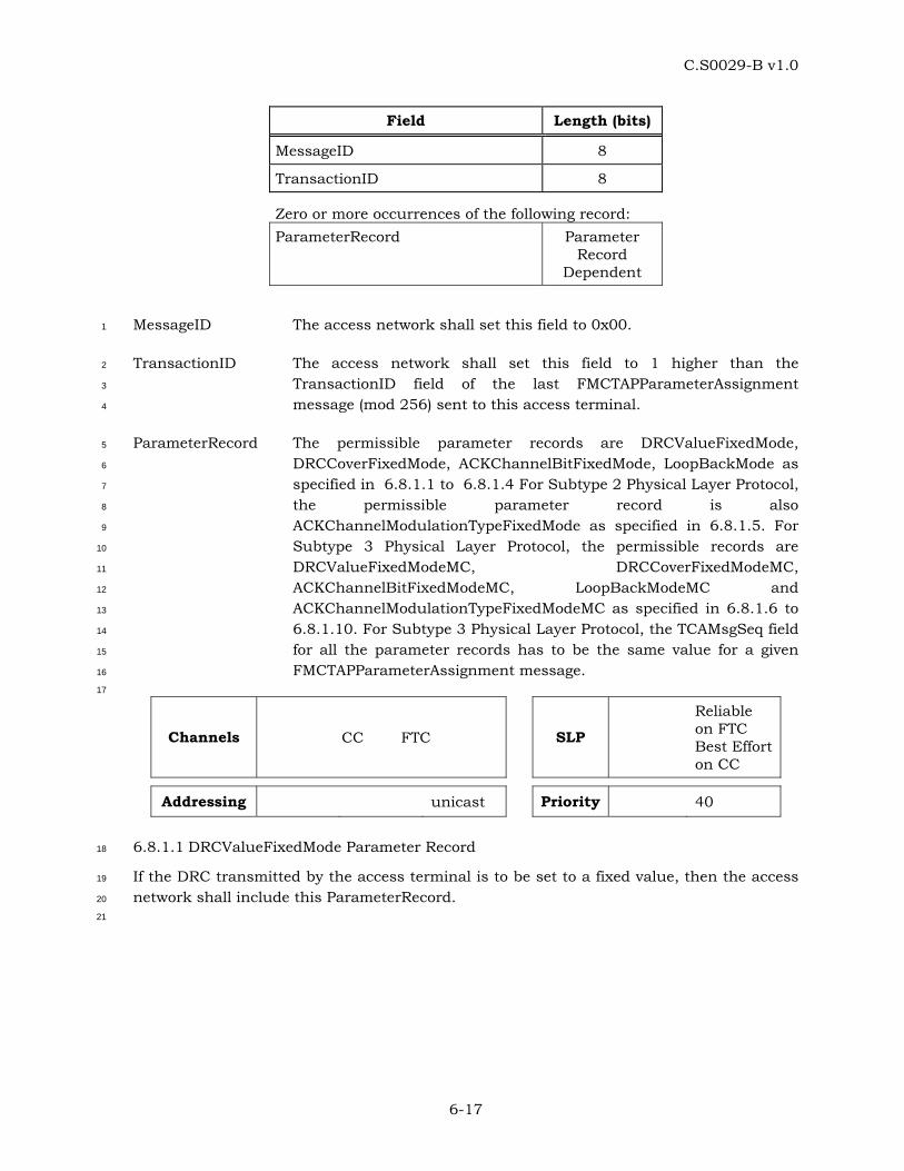
C.S0029-B v1.0
6-17
Field Length (bits)
MessageID 8
TransactionID 8
Zero or more occurrences of the following record: ParameterRecord Parameter
Record Dependent
MessageID The access network shall set this field to 0x00. 1
TransactionID The access network shall set this field to 1 higher than the 2
TransactionID field of the last FMCTAPParameterAssignment 3
message (mod 256) sent to this access terminal. 4
ParameterRecord The permissible parameter records are DRCValueFixedMode, 5
DRCCoverFixedMode, ACKChannelBitFixedMode, LoopBackMode as 6
specified in 6.8.1.1 to 6.8.1.4 For Subtype 2 Physical Layer Protocol, 7
the permissible parameter record is also 8
ACKChannelModulationTypeFixedMode as specified in 6.8.1.5. For 9
Subtype 3 Physical Layer Protocol, the permissible records are 10
DRCValueFixedModeMC, DRCCoverFixedModeMC, 11
ACKChannelBitFixedModeMC, LoopBackModeMC and 12
ACKChannelModulationTypeFixedModeMC as specified in 6.8.1.6 to 13
6.8.1.10. For Subtype 3 Physical Layer Protocol, the TCAMsgSeq field 14
for all the parameter records has to be the same value for a given 15
FMCTAPParameterAssignment message. 16
17
Channels CC FTC SLP
Reliable on FTC Best Effort on CC
Addressing unicast Priority 40
6.8.1.1 DRCValueFixedMode Parameter Record 18
If the DRC transmitted by the access terminal is to be set to a fixed value, then the access 19
network shall include this ParameterRecord. 20
21
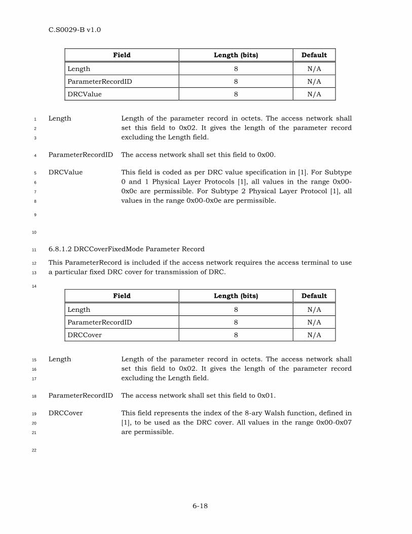
C.S0029-B v1.0
6-18
Field Length (bits) Default
Length 8 N/A
ParameterRecordID 8 N/A
DRCValue 8 N/A
Length Length of the parameter record in octets. The access network shall 1
set this field to 0x02. It gives the length of the parameter record 2
excluding the Length field. 3
ParameterRecordID The access network shall set this field to 0x00. 4
DRCValue This field is coded as per DRC value specification in [1]. For Subtype 5
0 and 1 Physical Layer Protocols [1], all values in the range 0x00-6
0x0c are permissible. For Subtype 2 Physical Layer Protocol [1], all 7
values in the range 0x00-0x0e are permissible. 8
9
10
6.8.1.2 DRCCoverFixedMode Parameter Record 11
This ParameterRecord is included if the access network requires the access terminal to use 12
a particular fixed DRC cover for transmission of DRC. 13
14
Field Length (bits) Default
Length 8 N/A
ParameterRecordID 8 N/A
DRCCover 8 N/A
Length Length of the parameter record in octets. The access network shall 15
set this field to 0x02. It gives the length of the parameter record 16
excluding the Length field. 17
ParameterRecordID The access network shall set this field to 0x01. 18
DRCCover This field represents the index of the 8-ary Walsh function, defined in 19
[1], to be used as the DRC cover. All values in the range 0x00-0x07 20
are permissible. 21
22
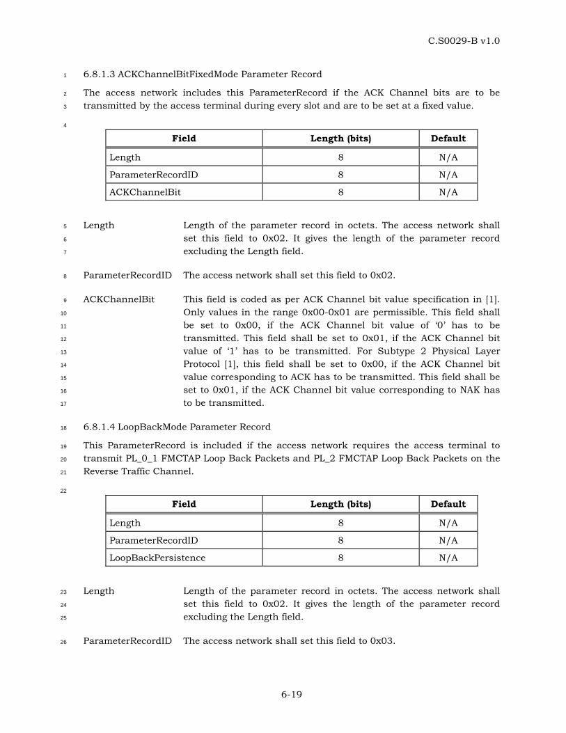
C.S0029-B v1.0
6-19
6.8.1.3 ACKChannelBitFixedMode Parameter Record 1
The access network includes this ParameterRecord if the ACK Channel bits are to be 2
transmitted by the access terminal during every slot and are to be set at a fixed value. 3
4
Field Length (bits) Default
Length 8 N/A
ParameterRecordID 8 N/A
ACKChannelBit 8 N/A
Length Length of the parameter record in octets. The access network shall 5
set this field to 0x02. It gives the length of the parameter record 6
excluding the Length field. 7
ParameterRecordID The access network shall set this field to 0x02. 8
ACKChannelBit This field is coded as per ACK Channel bit value specification in [1]. 9
Only values in the range 0x00-0x01 are permissible. This field shall 10
be set to 0x00, if the ACK Channel bit value of ‘0’ has to be 11
transmitted. This field shall be set to 0x01, if the ACK Channel bit 12
value of ‘1’ has to be transmitted. For Subtype 2 Physical Layer 13
Protocol [1], this field shall be set to 0x00, if the ACK Channel bit 14
value corresponding to ACK has to be transmitted. This field shall be 15
set to 0x01, if the ACK Channel bit value corresponding to NAK has 16
to be transmitted. 17
6.8.1.4 LoopBackMode Parameter Record 18
This ParameterRecord is included if the access network requires the access terminal to 19
transmit PL_0_1 FMCTAP Loop Back Packets and PL_2 FMCTAP Loop Back Packets on the 20
Reverse Traffic Channel. 21
22
Field Length (bits) Default
Length 8 N/A
ParameterRecordID 8 N/A
LoopBackPersistence 8 N/A
Length Length of the parameter record in octets. The access network shall 23
set this field to 0x02. It gives the length of the parameter record 24
excluding the Length field. 25
ParameterRecordID The access network shall set this field to 0x03. 26
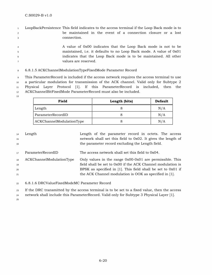
C.S0029-B v1.0
6-20
LoopBackPersistence This field indicates to the access terminal if the Loop Back mode is to 1
be maintained in the event of a connection closure or a lost 2
connection. 3
A value of 0x00 indicates that the Loop Back mode is not to be 4
maintained, i.e. it defaults to no Loop Back mode. A value of 0x01 5
indicates that the Loop Back mode is to be maintained. All other 6
values are reserved. 7
6.8.1.5 ACKChannelModulationTypeFixedMode Parameter Record 8
This ParameterRecord is included if the access network requires the access terminal to use 9
a particular modulation for transmission of the ACK channel. Valid only for Subtype 2 10
Physical Layer Protocol [1]. If this ParameterRecord is included, then the 11
ACKChannelBitFixedMode ParameterRecord must also be included. 12
13
Field Length (bits) Default
Length 8 N/A
ParameterRecordID 8 N/A
ACKChannelModulationType 8 N/A
Length Length of the parameter record in octets. The access 14
network shall set this field to 0x02. It gives the length of 15
the parameter record excluding the Length field. 16
ParameterRecordID The access network shall set this field to 0x04. 17
ACKChannelModulationType Only values in the range 0x00-0x01 are permissible. This 18
field shall be set to 0x00 if the ACK Channel modulation is 19
BPSK as specified in [1]. This field shall be set to 0x01 if 20
the ACK Channel modulation is OOK as specified in [1]. 21
6.8.1.6 DRCValueFixedModeMC Parameter Record 22
If the DRC transmitted by the access terminal is to be set to a fixed value, then the access 23
network shall include this ParameterRecord. Valid only for Subtype 3 Physical Layer [1]. 24
25
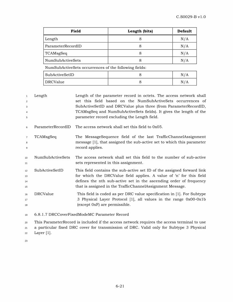
C.S0029-B v1.0
6-21
Field Length (bits) Default
Length 8 N/A
ParameterRecordID 8 N/A
TCAMsgSeq 8 N/A
NumSubActiveSets 8 N/A
NumSubActiveSets occurrences of the following fields:
SubActiveSetID 8 N/A
DRCValue 8 N/A
Length Length of the parameter record in octets. The access network shall 1
set this field based on the NumSubActiveSets occurrences of 2
SubActiveSetID and DRCValue plus three (from ParameterRecordID, 3
TCAMsgSeq and NumSubActiveSets fields). It gives the length of the 4
parameter record excluding the Length field. 5
ParameterRecordID The access network shall set this field to 0x05. 6
TCAMsgSeq The MessageSequence field of the last TrafficChannelAssignment 7
message [1], that assigned the sub-active set to which this parameter 8
record applies. 9
NumSubActiveSets The access network shall set this field to the number of sub-active 10
sets represented in this assignment. 11
SubActiveSetID This field contains the sub-active set ID of the assigned forward link 12
for which the DRCValue field applies. A value of ‘n’ for this field 13
defines the nth sub-active set in the ascending order of frequency 14
that is assigned in the TrafficChannelAssignment Message. 15
DRCValue This field is coded as per DRC value specification in [1]. For Subtype 16
3 Physical Layer Protocol [1], all values in the range 0x00-0x1b 17
(except 0xF) are permissible. 18
6.8.1.7 DRCCoverFixedModeMC Parameter Record 19
This ParameterRecord is included if the access network requires the access terminal to use 20
a particular fixed DRC cover for transmission of DRC. Valid only for Subtype 3 Physical 21
Layer [1]. 22
23
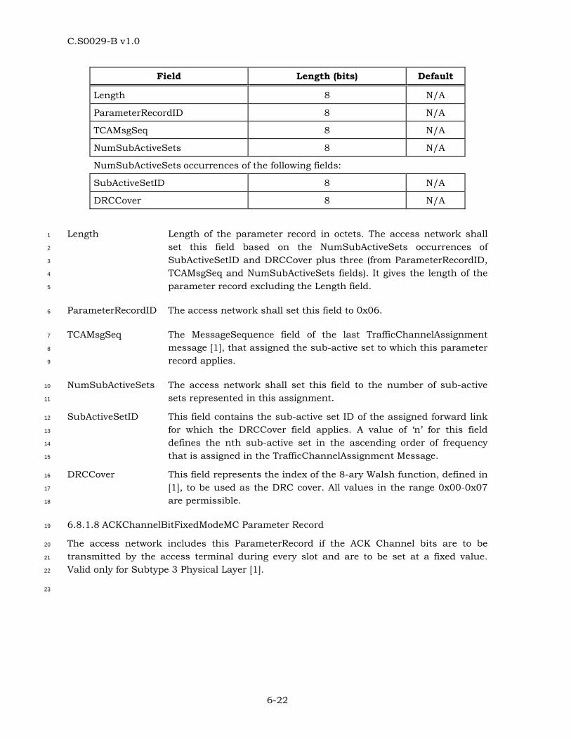
C.S0029-B v1.0
6-22
Field Length (bits) Default
Length 8 N/A
ParameterRecordID 8 N/A
TCAMsgSeq 8 N/A
NumSubActiveSets 8 N/A
NumSubActiveSets occurrences of the following fields:
SubActiveSetID 8 N/A
DRCCover 8 N/A
Length Length of the parameter record in octets. The access network shall 1
set this field based on the NumSubActiveSets occurrences of 2
SubActiveSetID and DRCCover plus three (from ParameterRecordID, 3
TCAMsgSeq and NumSubActiveSets fields). It gives the length of the 4
parameter record excluding the Length field. 5
ParameterRecordID The access network shall set this field to 0x06. 6
TCAMsgSeq The MessageSequence field of the last TrafficChannelAssignment 7
message [1], that assigned the sub-active set to which this parameter 8
record applies. 9
NumSubActiveSets The access network shall set this field to the number of sub-active 10
sets represented in this assignment. 11
SubActiveSetID This field contains the sub-active set ID of the assigned forward link 12
for which the DRCCover field applies. A value of ‘n’ for this field 13
defines the nth sub-active set in the ascending order of frequency 14
that is assigned in the TrafficChannelAssignment Message. 15
DRCCover This field represents the index of the 8-ary Walsh function, defined in 16
[1], to be used as the DRC cover. All values in the range 0x00-0x07 17
are permissible. 18
6.8.1.8 ACKChannelBitFixedModeMC Parameter Record 19
The access network includes this ParameterRecord if the ACK Channel bits are to be 20
transmitted by the access terminal during every slot and are to be set at a fixed value. 21
Valid only for Subtype 3 Physical Layer [1]. 22
23

C.S0029-B v1.0
6-23
Field Length (bits) Default
Length 8 N/A
ParameterRecordID 8 N/A
TCAMsgSeq 8 N/A
NumSubActiveSets 8 N/A
SubActiveSetNumber occurrences of the following fields:
SubActiveSetID 8 N/A
ACKChannelBit 8 N/A
Length Length of the parameter record in octets. The access network shall 1
set this field based on the NumSubActiveSets occurrences of the 2
SubActiveSetID and ACKChannelBit fields plus three (from 3
ParameterRecordID, TCAMsgSeq and NumSubActiveSets fields). It 4
gives the length of the parameter record excluding the Length field. 5
ParameterRecordID The access network shall set this field to 0x07. 6
TCAMsgSeq The MessageSequence field of the last TrafficChannelAssignment 7
message [1], that assigned the sub-active set to which this parameter 8
record applies. 9
NumSubActiveSets The access network shall set this field to the number of sub-active 10
sets represented in this assignment. 11
SubActiveSetID This field contains the sub-active set ID of the assigned forward link 12
for which the ACKChannelBit field applies. A value of ‘n’ for this field 13
defines the nth sub-active set in the ascending order of frequency 14
that is assigned in the TrafficChannelAssignment Message. 15
ACKChannelBit This field is coded as per ACK Channel bit value specification in [1]. 16
Only values in the range 0x00-0x01 are permissible. This field shall 17
be set to 0x00, if the ACK Channel bit value of ‘0’ has to be 18
transmitted. This field shall be set to 0x01, if the ACK Channel bit 19
value of ‘1’ has to be transmitted. This field shall be set to 0x00, if 20
the ACK Channel bit value corresponding to ACK has to be 21
transmitted. This field shall be set to 0x01, if the ACK Channel bit 22
value corresponding to NAK has to be transmitted. 23
6.8.1.9 LoopBackModeMC Parameter Record 24
This ParameterRecord is included if the access network requires the access terminal to 25
transmit PL_3 FMCTAP Loop Back Packets on the Reverse Traffic Channel. Valid only for 26
Subtype 3 Physical Layer [1]. 27
28
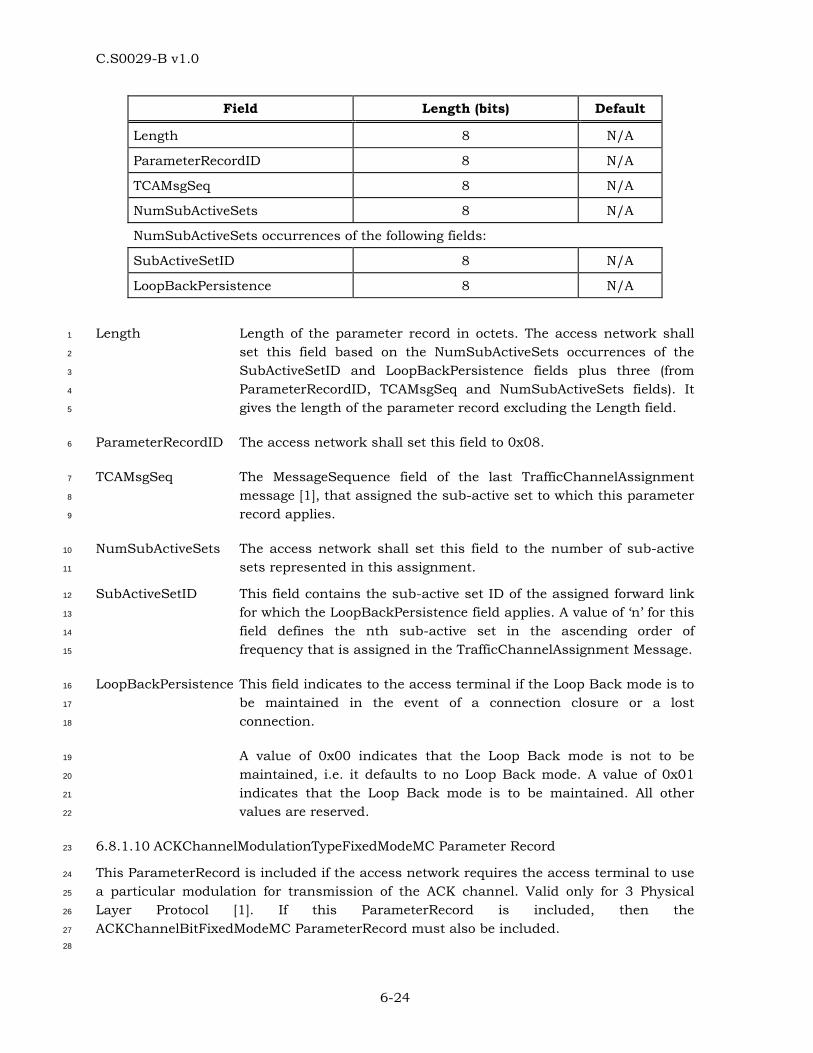
C.S0029-B v1.0
6-24
Field Length (bits) Default
Length 8 N/A
ParameterRecordID 8 N/A
TCAMsgSeq 8 N/A
NumSubActiveSets 8 N/A
NumSubActiveSets occurrences of the following fields:
SubActiveSetID 8 N/A
LoopBackPersistence 8 N/A
Length Length of the parameter record in octets. The access network shall 1
set this field based on the NumSubActiveSets occurrences of the 2
SubActiveSetID and LoopBackPersistence fields plus three (from 3
ParameterRecordID, TCAMsgSeq and NumSubActiveSets fields). It 4
gives the length of the parameter record excluding the Length field. 5
ParameterRecordID The access network shall set this field to 0x08. 6
TCAMsgSeq The MessageSequence field of the last TrafficChannelAssignment 7
message [1], that assigned the sub-active set to which this parameter 8
record applies. 9
NumSubActiveSets The access network shall set this field to the number of sub-active 10
sets represented in this assignment. 11
SubActiveSetID This field contains the sub-active set ID of the assigned forward link 12
for which the LoopBackPersistence field applies. A value of ‘n’ for this 13
field defines the nth sub-active set in the ascending order of 14
frequency that is assigned in the TrafficChannelAssignment Message. 15
LoopBackPersistence This field indicates to the access terminal if the Loop Back mode is to 16
be maintained in the event of a connection closure or a lost 17
connection. 18
A value of 0x00 indicates that the Loop Back mode is not to be 19
maintained, i.e. it defaults to no Loop Back mode. A value of 0x01 20
indicates that the Loop Back mode is to be maintained. All other 21
values are reserved. 22
6.8.1.10 ACKChannelModulationTypeFixedModeMC Parameter Record 23
This ParameterRecord is included if the access network requires the access terminal to use 24
a particular modulation for transmission of the ACK channel. Valid only for 3 Physical 25
Layer Protocol [1]. If this ParameterRecord is included, then the 26
ACKChannelBitFixedModeMC ParameterRecord must also be included. 27
28
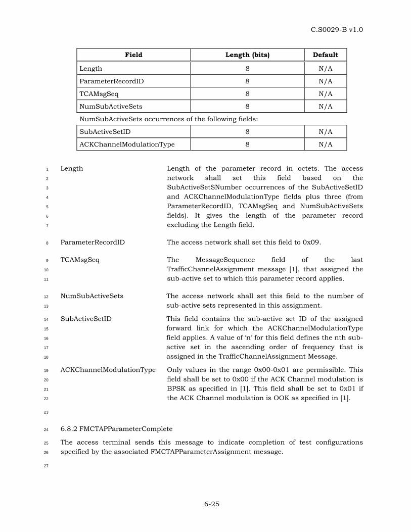
C.S0029-B v1.0
6-25
Field Length (bits) Default
Length 8 N/A
ParameterRecordID 8 N/A
TCAMsgSeq 8 N/A
NumSubActiveSets 8 N/A
NumSubActiveSets occurrences of the following fields:
SubActiveSetID 8 N/A
ACKChannelModulationType 8 N/A
Length Length of the parameter record in octets. The access 1
network shall set this field based on the 2
SubActiveSetSNumber occurrences of the SubActiveSetID 3
and ACKChannelModulationType fields plus three (from 4
ParameterRecordID, TCAMsgSeq and NumSubActiveSets 5
fields). It gives the length of the parameter record 6
excluding the Length field. 7
ParameterRecordID The access network shall set this field to 0x09. 8
TCAMsgSeq The MessageSequence field of the last 9
TrafficChannelAssignment message [1], that assigned the 10
sub-active set to which this parameter record applies. 11
NumSubActiveSets The access network shall set this field to the number of 12
sub-active sets represented in this assignment. 13
SubActiveSetID This field contains the sub-active set ID of the assigned 14
forward link for which the ACKChannelModulationType 15
field applies. A value of ‘n’ for this field defines the nth sub-16
active set in the ascending order of frequency that is 17
assigned in the TrafficChannelAssignment Message. 18
ACKChannelModulationType Only values in the range 0x00-0x01 are permissible. This 19
field shall be set to 0x00 if the ACK Channel modulation is 20
BPSK as specified in [1]. This field shall be set to 0x01 if 21
the ACK Channel modulation is OOK as specified in [1]. 22
23
6.8.2 FMCTAPParameterComplete 24
The access terminal sends this message to indicate completion of test configurations 25
specified by the associated FMCTAPParameterAssignment message. 26
27
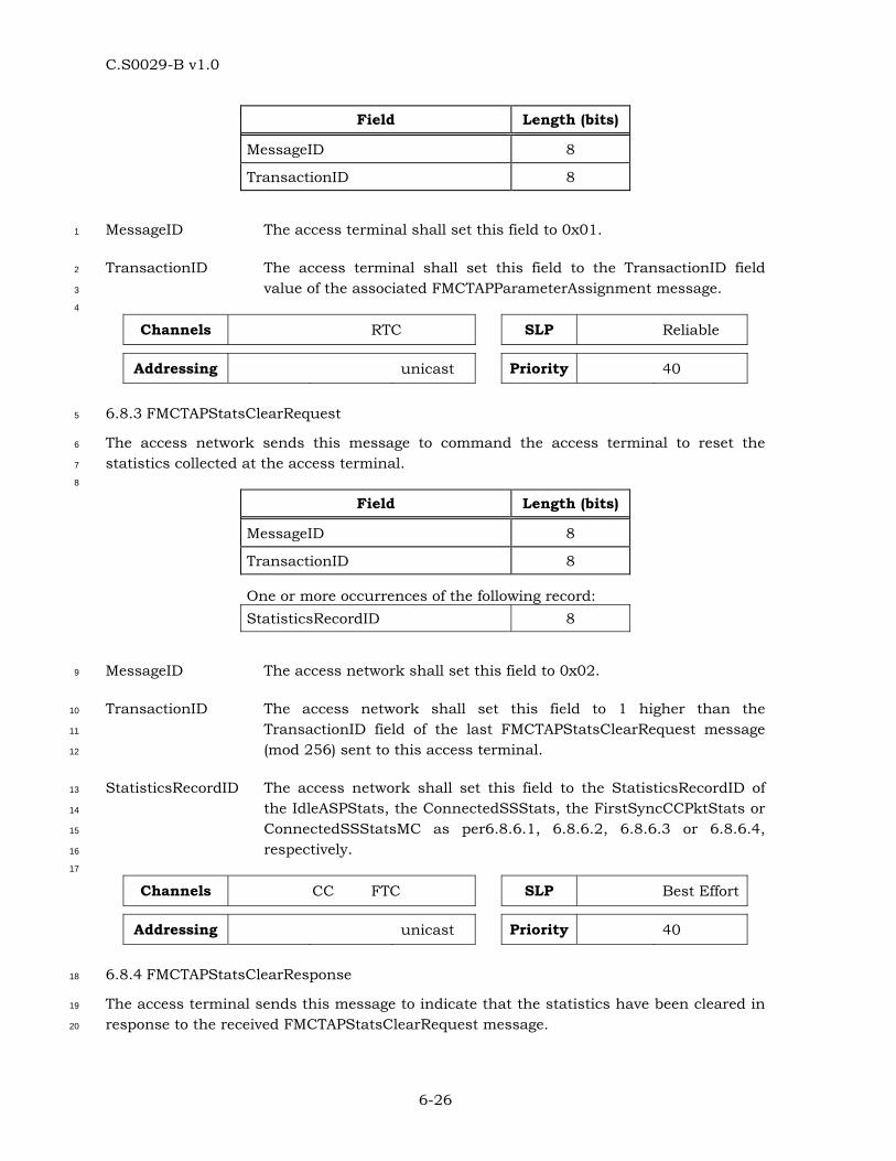
C.S0029-B v1.0
6-26
Field Length (bits)
MessageID 8
TransactionID 8
MessageID The access terminal shall set this field to 0x01. 1
TransactionID The access terminal shall set this field to the TransactionID field 2
value of the associated FMCTAPParameterAssignment message. 3
4
Channels RTC SLP Reliable
Addressing unicast Priority 40
6.8.3 FMCTAPStatsClearRequest 5
The access network sends this message to command the access terminal to reset the 6
statistics collected at the access terminal. 7
8
Field Length (bits)
MessageID 8
TransactionID 8
One or more occurrences of the following record: StatisticsRecordID 8
MessageID The access network shall set this field to 0x02. 9
TransactionID The access network shall set this field to 1 higher than the 10
TransactionID field of the last FMCTAPStatsClearRequest message 11
(mod 256) sent to this access terminal. 12
StatisticsRecordID The access network shall set this field to the StatisticsRecordID of 13
the IdleASPStats, the ConnectedSSStats, the FirstSyncCCPktStats or 14
ConnectedSSStatsMC as per6.8.6.1, 6.8.6.2, 6.8.6.3 or 6.8.6.4, 15
respectively. 16
17
Channels CC FTC SLP Best Effort
Addressing unicast Priority 40
6.8.4 FMCTAPStatsClearResponse 18
The access terminal sends this message to indicate that the statistics have been cleared in 19
response to the received FMCTAPStatsClearRequest message. 20
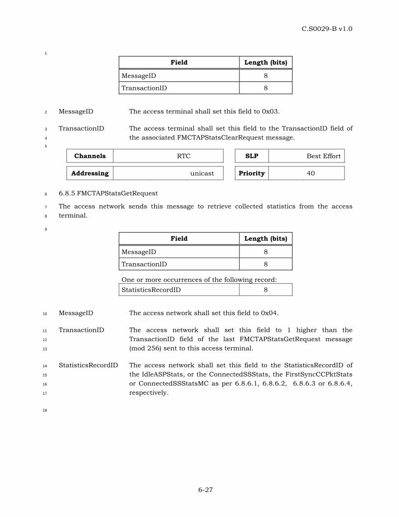
C.S0029-B v1.0
6-27
1
Field Length (bits)
MessageID 8
TransactionID 8
MessageID The access terminal shall set this field to 0x03. 2
TransactionID The access terminal shall set this field to the TransactionID field of 3
the associated FMCTAPStatsClearRequest message. 4
5
Channels RTC SLP Best Effort
Addressing unicast Priority 40
6.8.5 FMCTAPStatsGetRequest 6
The access network sends this message to retrieve collected statistics from the access 7
terminal. 8
9
Field Length (bits)
MessageID 8
TransactionID 8
One or more occurrences of the following record: StatisticsRecordID 8
MessageID The access network shall set this field to 0x04. 10
TransactionID The access network shall set this field to 1 higher than the 11
TransactionID field of the last FMCTAPStatsGetRequest message 12
(mod 256) sent to this access terminal. 13
StatisticsRecordID The access network shall set this field to the StatisticsRecordID of 14
the IdleASPStats, or the ConnectedSSStats, the FirstSyncCCPktStats 15
or ConnectedSSStatsMC as per 6.8.6.1, 6.8.6.2, 6.8.6.3 or 6.8.6.4, 16
respectively. 17
18
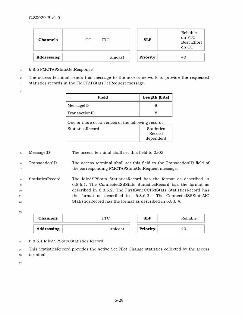
C.S0029-B v1.0
6-28
Channels CC FTC SLP
Reliable on FTC Best Effort on CC
Addressing unicast Priority 40
6.8.6 FMCTAPStatsGetResponse 1
The access terminal sends this message to the access network to provide the requested 2
statistics records in the FMCTAPStatsGetRequest message. 3
4
Field Length (bits)
MessageID 8
TransactionID 8
One or more occurrences of the following record: StatisticsRecord Statistics
Record dependent
MessageID The access terminal shall set this field to 0x05. 5
TransactionID The access terminal shall set this field to the TransactionID field of 6
the corresponding FMCTAPStatsGetRequest message. 7
StatisticsRecord The IdleASPStats StatisticsRecord has the format as described in 8
6.8.6.1. The ConnectedSSStats StatisticsRecord has the format as 9
described in 6.8.6.2. The FirstSyncCCPktStats StatisticsRecord has 10
the format as described in 6.8.6.3. The ConnectedSSStatsMC 11
StatisticsRecord has the format as described in 6.8.6.4. 12
13
Channels RTC SLP Reliable
Addressing unicast Priority 40
6.8.6.1 IdleASPStats Statistics Record 14
This StatisticsRecord provides the Active Set Pilot Change statistics collected by the access 15
terminal. 16
17
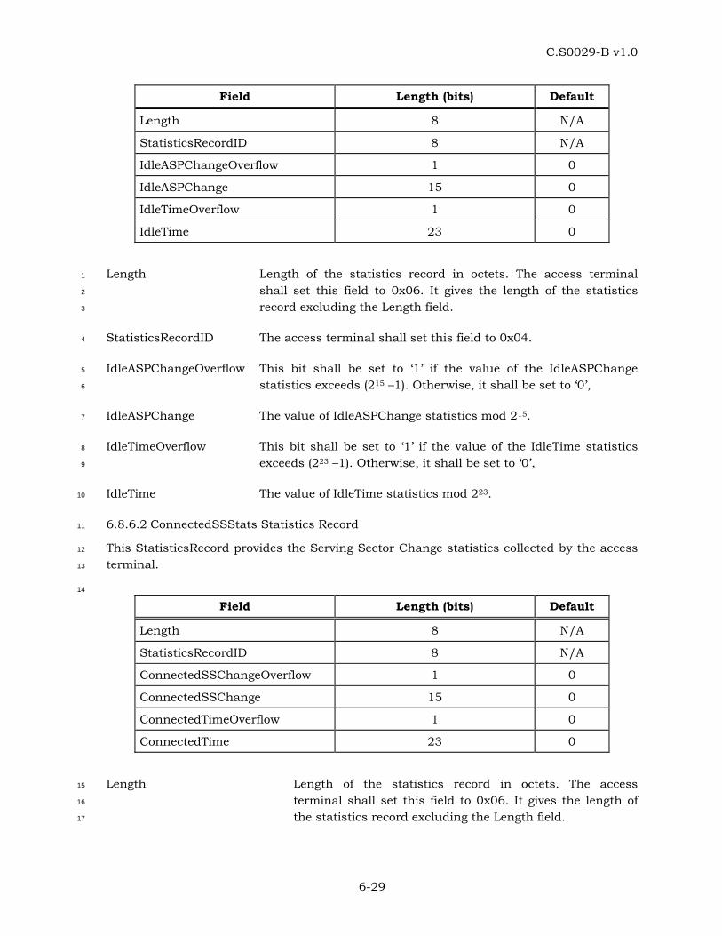
C.S0029-B v1.0
6-29
Field Length (bits) Default
Length 8 N/A
StatisticsRecordID 8 N/A
IdleASPChangeOverflow 1 0
IdleASPChange 15 0
IdleTimeOverflow 1 0
IdleTime 23 0
Length Length of the statistics record in octets. The access terminal 1
shall set this field to 0x06. It gives the length of the statistics 2
record excluding the Length field. 3
StatisticsRecordID The access terminal shall set this field to 0x04. 4
IdleASPChangeOverflow This bit shall be set to ‘1’ if the value of the IdleASPChange 5
statistics exceeds (215 –1). Otherwise, it shall be set to ‘0’, 6
IdleASPChange The value of IdleASPChange statistics mod 215. 7
IdleTimeOverflow This bit shall be set to ‘1’ if the value of the IdleTime statistics 8
exceeds (223 –1). Otherwise, it shall be set to ‘0’, 9
IdleTime The value of IdleTime statistics mod 223. 10
6.8.6.2 ConnectedSSStats Statistics Record 11
This StatisticsRecord provides the Serving Sector Change statistics collected by the access 12
terminal. 13
14
Field Length (bits) Default
Length 8 N/A
StatisticsRecordID 8 N/A
ConnectedSSChangeOverflow 1 0
ConnectedSSChange 15 0
ConnectedTimeOverflow 1 0
ConnectedTime 23 0
Length Length of the statistics record in octets. The access 15
terminal shall set this field to 0x06. It gives the length of 16
the statistics record excluding the Length field. 17
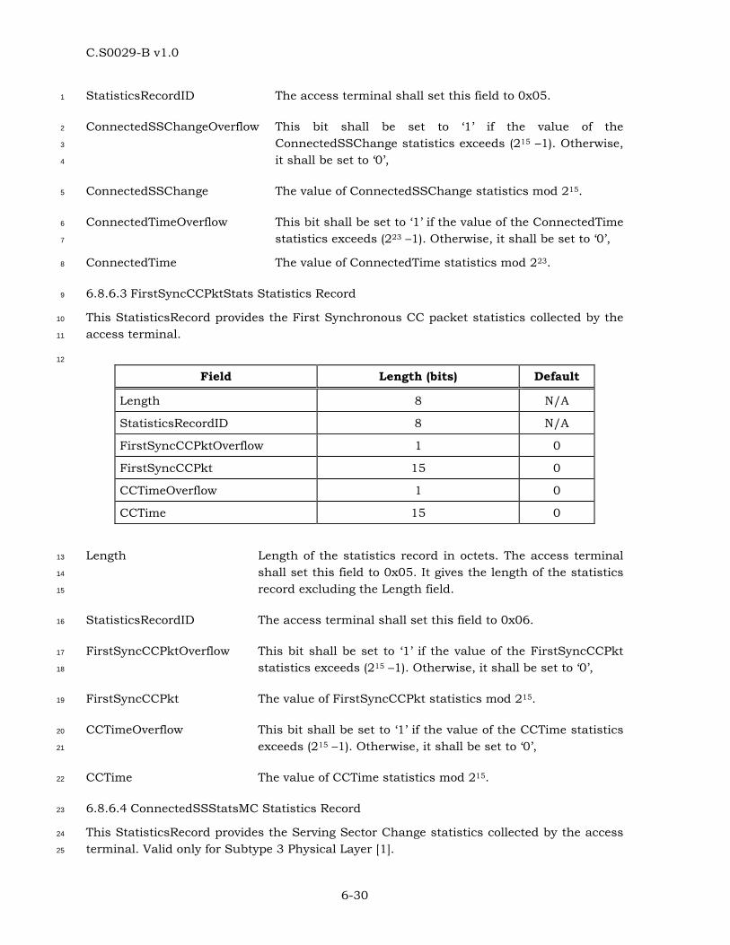
C.S0029-B v1.0
6-30
StatisticsRecordID The access terminal shall set this field to 0x05. 1
ConnectedSSChangeOverflow This bit shall be set to ‘1’ if the value of the 2
ConnectedSSChange statistics exceeds (215 –1). Otherwise, 3
it shall be set to ‘0’, 4
ConnectedSSChange The value of ConnectedSSChange statistics mod 215. 5
ConnectedTimeOverflow This bit shall be set to ‘1’ if the value of the ConnectedTime 6
statistics exceeds (223 –1). Otherwise, it shall be set to ‘0’, 7
ConnectedTime The value of ConnectedTime statistics mod 223. 8
6.8.6.3 FirstSyncCCPktStats Statistics Record 9
This StatisticsRecord provides the First Synchronous CC packet statistics collected by the 10
access terminal. 11
12
Field Length (bits) Default
Length 8 N/A
StatisticsRecordID 8 N/A
FirstSyncCCPktOverflow 1 0
FirstSyncCCPkt 15 0
CCTimeOverflow 1 0
CCTime 15 0
Length Length of the statistics record in octets. The access terminal 13
shall set this field to 0x05. It gives the length of the statistics 14
record excluding the Length field. 15
StatisticsRecordID The access terminal shall set this field to 0x06. 16
FirstSyncCCPktOverflow This bit shall be set to ‘1’ if the value of the FirstSyncCCPkt 17
statistics exceeds (215 –1). Otherwise, it shall be set to ‘0’, 18
FirstSyncCCPkt The value of FirstSyncCCPkt statistics mod 215. 19
CCTimeOverflow This bit shall be set to ‘1’ if the value of the CCTime statistics 20
exceeds (215 –1). Otherwise, it shall be set to ‘0’, 21
CCTime The value of CCTime statistics mod 215. 22
6.8.6.4 ConnectedSSStatsMC Statistics Record 23
This StatisticsRecord provides the Serving Sector Change statistics collected by the access 24
terminal. Valid only for Subtype 3 Physical Layer [1]. 25
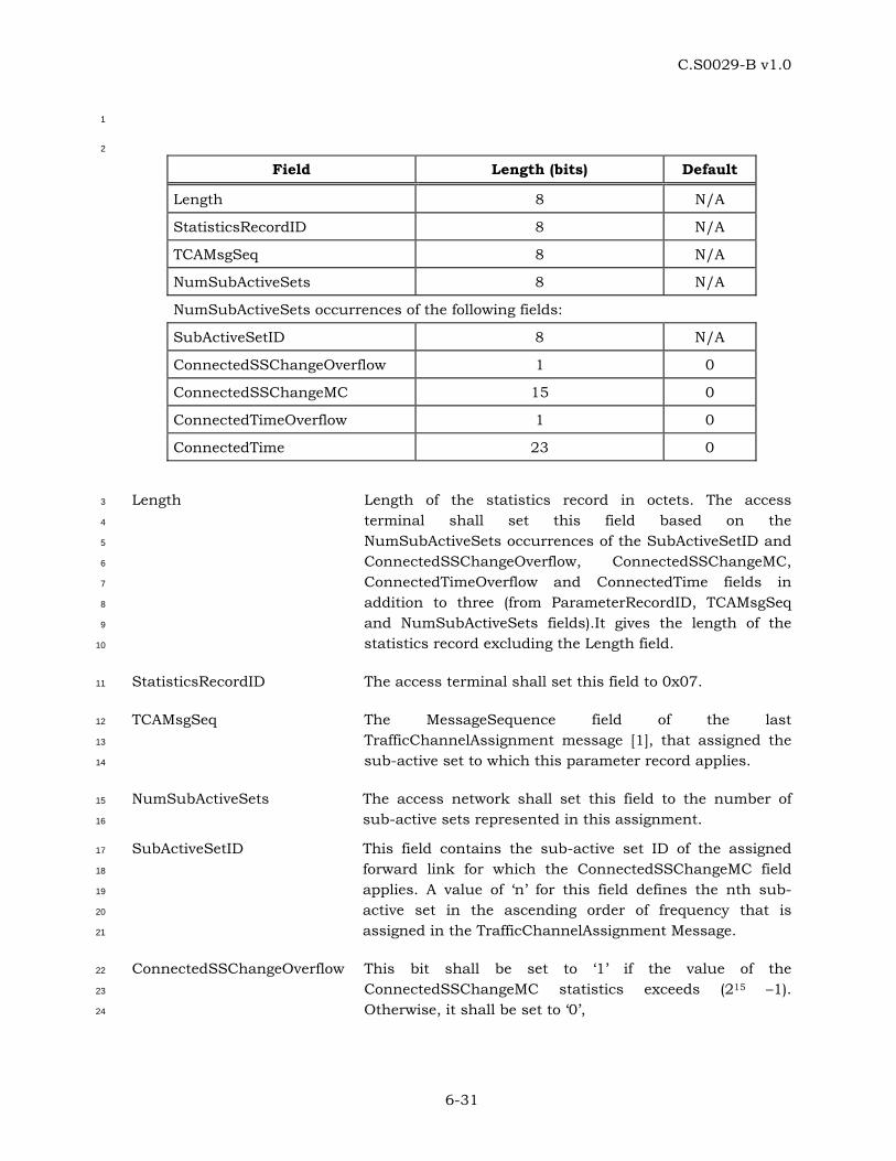
C.S0029-B v1.0
6-31
1
2
Field Length (bits) Default
Length 8 N/A
StatisticsRecordID 8 N/A
TCAMsgSeq 8 N/A
NumSubActiveSets 8 N/A
NumSubActiveSets occurrences of the following fields:
SubActiveSetID 8 N/A
ConnectedSSChangeOverflow 1 0
ConnectedSSChangeMC 15 0
ConnectedTimeOverflow 1 0
ConnectedTime 23 0
Length Length of the statistics record in octets. The access 3
terminal shall set this field based on the 4
NumSubActiveSets occurrences of the SubActiveSetID and 5
ConnectedSSChangeOverflow, ConnectedSSChangeMC, 6
ConnectedTimeOverflow and ConnectedTime fields in 7
addition to three (from ParameterRecordID, TCAMsgSeq 8
and NumSubActiveSets fields).It gives the length of the 9
statistics record excluding the Length field. 10
StatisticsRecordID The access terminal shall set this field to 0x07. 11
TCAMsgSeq The MessageSequence field of the last 12
TrafficChannelAssignment message [1], that assigned the 13
sub-active set to which this parameter record applies. 14
NumSubActiveSets The access network shall set this field to the number of 15
sub-active sets represented in this assignment. 16
SubActiveSetID This field contains the sub-active set ID of the assigned 17
forward link for which the ConnectedSSChangeMC field 18
applies. A value of ‘n’ for this field defines the nth sub-19
active set in the ascending order of frequency that is 20
assigned in the TrafficChannelAssignment Message. 21
ConnectedSSChangeOverflow This bit shall be set to ‘1’ if the value of the 22
ConnectedSSChangeMC statistics exceeds (215 –1). 23
Otherwise, it shall be set to ‘0’, 24

C.S0029-B v1.0
6-32
ConnectedSSChangeMC The value of ConnectedSSChangeMC statistics mod 215 for 1
sub-active set index j. 2
ConnectedTimeOverflow This bit shall be set to ‘1’ if the value of the ConnectedTime 3
statistics exceeds (223 –1). Otherwise, it shall be set to ‘0’, 4
ConnectedTime The value of ConnectedTime statistics mod 223. 5
6.9 FMCTAP Packet Formats 6
6.9.1 PL_0_1_2_3 FMCTAP Test Packet 7
The access network transmits these packets on the Forward Traffic Channel. 8
9
Field Length (bits)
ProtocolID 2
PacketType 4
SEQ 14
Reserved 2
FTC_PL_0_1_2_3Pseudorandom Fill Variable
ProtocolID This field identifies the protocol to which this packet 10
belongs. This field shall be set to ‘00’ for the FMCTAP 11
packets. 12
PacketType This field identifies the packet type within the FMCTAP. 13
This field shall be set to 0x0. 14
SEQ The sequence number of this PL_0_1_2_3 FMCTAP Test 15
Packet. This is set to the value of V(STest) when the 16
packet is generated. For Subtype 3 Physical Layer, the 17
sequence number shall be generated independently for 18
each sub-active set. 19
Reserved The access network shall set this field to zero. The 20
access terminal shall ignore this field. 21
FTC_PL_0_1_2_3Pseudorandom Fill The access network shall include fill bits that are 22
extracted from a circular buffer that stores bits 23
corresponding to one period of any Maximal Length (ML) 24
Sequence of degree 15 or higher. The 25
FTC_PL_0_1_2_3Pseudorandom Fill field length shall be 26
such as to fill up a single FTC MAC Layer packet. For 27
example, with characteristic polynomial p(x) = x15+x+1, 28
one period of the ML sequence can be generated using a 29
15-state Simple Shift Register Generator in Fibonacci 30
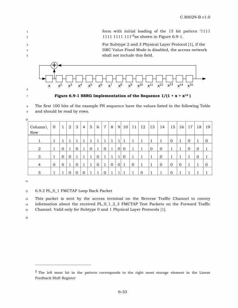
C.S0029-B v1.0
6-33
form with initial loading of the 15 bit pattern ‘1111 1
1111 1111 111’5as shown in Figure 6.9-1. 2
For Subtype 2 and 3 Physical Layer Protocol [1], if the 3
DRC Value Fixed Mode is disabled, the access network 4
shall not include this field. 5
+
x x2 x3 x4 x5 x6 x7 x8 x9 x10 x11 x12 x13 x14 x15 6
Figure 6.9-1 SSRG Implementation of the Sequence 1/(1 + x + x15 ) 7
The first 100 bits of the example PN sequence have the values listed in the following Table 8
and should be read by rows. 9
10
Column\ Row
0 1 2 3 4 5 6 7 8 9 10 11 12 13 14 15 16 17 18 19
1 1 1 1 1 1 1 1 1 1 1 1 1 1 1 1 0 1 0 1 0
2 1 0 1 0 1 0 1 0 1 0 0 1 1 0 0 1 1 0 0 1
3 1 0 0 1 1 1 0 1 1 1 0 1 1 1 0 1 1 1 0 1
4 0 0 1 0 1 1 0 1 0 0 1 0 1 1 0 0 0 1 1 0
5 1 1 0 0 0 1 1 0 1 1 1 1 0 1 1 0 1 1 1 1
11
6.9.2 PL_0_1 FMCTAP Loop Back Packet 12
This packet is sent by the access terminal on the Reverse Traffic Channel to convey 13
information about the received PL_0_1_2_3 FMCTAP Test Packets on the Forward Traffic 14
Channel. Valid only for Subtype 0 and 1 Physical Layer Protocols [1]. 15
16
5 The left most bit in the pattern corresponds to the right most storage element in the Linear Feedback Shift Register
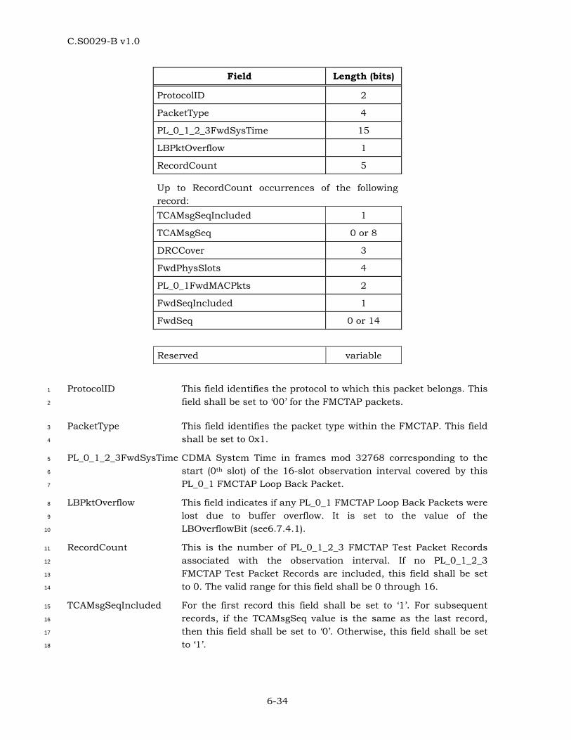
C.S0029-B v1.0
6-34
Field Length (bits)
ProtocolID 2
PacketType 4
PL_0_1_2_3FwdSysTime 15
LBPktOverflow 1
RecordCount 5
Up to RecordCount occurrences of the following record: TCAMsgSeqIncluded 1
TCAMsgSeq 0 or 8
DRCCover 3
FwdPhysSlots 4
PL_0_1FwdMACPkts 2
FwdSeqIncluded 1
FwdSeq 0 or 14
Reserved variable
ProtocolID This field identifies the protocol to which this packet belongs. This 1
field shall be set to ‘00’ for the FMCTAP packets. 2
PacketType This field identifies the packet type within the FMCTAP. This field 3
shall be set to 0x1. 4
PL_0_1_2_3FwdSysTime CDMA System Time in frames mod 32768 corresponding to the 5
start (0th slot) of the 16-slot observation interval covered by this 6
PL_0_1 FMCTAP Loop Back Packet. 7
LBPktOverflow This field indicates if any PL_0_1 FMCTAP Loop Back Packets were 8
lost due to buffer overflow. It is set to the value of the 9
LBOverflowBit (see6.7.4.1). 10
RecordCount This is the number of PL_0_1_2_3 FMCTAP Test Packet Records 11
associated with the observation interval. If no PL_0_1_2_3 12
FMCTAP Test Packet Records are included, this field shall be set 13
to 0. The valid range for this field shall be 0 through 16. 14
TCAMsgSeqIncluded For the first record this field shall be set to ‘1’. For subsequent 15
records, if the TCAMsgSeq value is the same as the last record, 16
then this field shall be set to ‘0’. Otherwise, this field shall be set 17
to ‘1’. 18
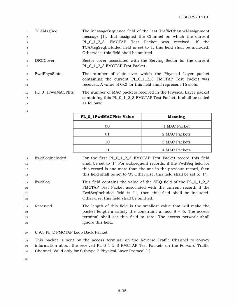
C.S0029-B v1.0
6-35
TCAMsgSeq The MessageSequence field of the last TrafficChannelAssignment 1
message [1], that assigned the Channel on which the current 2
PL_0_1_2_3 FMCTAP Test Packet was received. If the 3
TCAMsgSeqIncluded field is set to 1, this field shall be included. 4
Otherwise, this field shall be omitted. 5
DRCCover Sector cover associated with the Serving Sector for the current 6
PL_0_1_2_3 FMCTAP Test Packet. 7
FwdPhysSlots The number of slots over which the Physical Layer packet 8
containing the current PL_0_1_2_3 FMCTAP Test Packet was 9
received. A value of 0x0 for this field shall represent 16 slots. 10
PL_0_1FwdMACPkts The number of MAC packets received in the Physical Layer packet 11
containing this PL_0_1_2_3 FMCTAP Test Packet. It shall be coded 12
as follows: 13
14
PL_0_1FwdMACPkts Value Meaning
00 1 MAC Packet
01 2 MAC Packets
10 3 MAC Packets
11 4 MAC Packets
FwdSeqIncluded For the first PL_0_1_2_3 FMCTAP Test Packet record this field 15
shall be set to ‘1’. For subsequent records, if the FwdSeq field for 16
this record is one more than the one in the previous record, then 17
this field shall be set to ‘0’. Otherwise, this field shall be set to ‘1’. 18
FwdSeq This field contains the value of the SEQ field of the PL_0_1_2_3 19
FMCTAP Test Packet associated with the current record. If the 20
FwdSeqIncluded field is ‘1’, then this field shall be included. 21
Otherwise, this field shall be omitted. 22
Reserved The length of this field is the smallest value that will make the 23
packet length x satisfy the constraint x mod 8 = 6. The access 24
terminal shall set this field to zero. The access network shall 25
ignore this field. 26
6.9.3 PL_2 FMCTAP Loop Back Packet 27
This packet is sent by the access terminal on the Reverse Traffic Channel to convey 28
information about the received PL_0_1_2_3 FMCTAP Test Packets on the Forward Traffic 29
Channel. Valid only for Subtype 2 Physical Layer Protocol [1]. 30
31
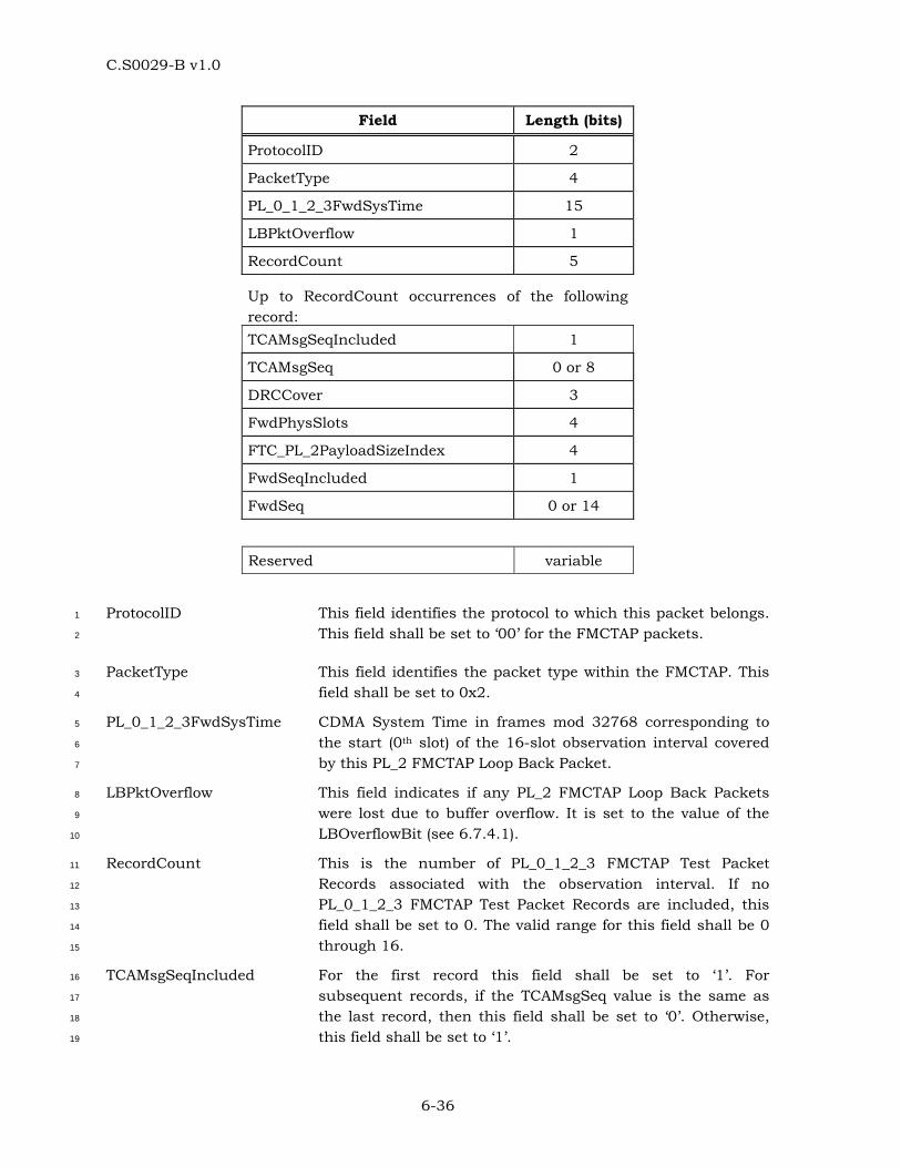
C.S0029-B v1.0
6-36
Field Length (bits)
ProtocolID 2
PacketType 4
PL_0_1_2_3FwdSysTime 15
LBPktOverflow 1
RecordCount 5
Up to RecordCount occurrences of the following record: TCAMsgSeqIncluded 1
TCAMsgSeq 0 or 8
DRCCover 3
FwdPhysSlots 4
FTC_PL_2PayloadSizeIndex 4
FwdSeqIncluded 1
FwdSeq 0 or 14
Reserved variable
ProtocolID This field identifies the protocol to which this packet belongs. 1
This field shall be set to ‘00’ for the FMCTAP packets. 2
PacketType This field identifies the packet type within the FMCTAP. This 3
field shall be set to 0x2. 4
PL_0_1_2_3FwdSysTime CDMA System Time in frames mod 32768 corresponding to 5
the start (0th slot) of the 16-slot observation interval covered 6
by this PL_2 FMCTAP Loop Back Packet. 7
LBPktOverflow This field indicates if any PL_2 FMCTAP Loop Back Packets 8
were lost due to buffer overflow. It is set to the value of the 9
LBOverflowBit (see 6.7.4.1). 10
RecordCount This is the number of PL_0_1_2_3 FMCTAP Test Packet 11
Records associated with the observation interval. If no 12
PL_0_1_2_3 FMCTAP Test Packet Records are included, this 13
field shall be set to 0. The valid range for this field shall be 0 14
through 16. 15
TCAMsgSeqIncluded For the first record this field shall be set to ‘1’. For 16
subsequent records, if the TCAMsgSeq value is the same as 17
the last record, then this field shall be set to ‘0’. Otherwise, 18
this field shall be set to ‘1’. 19
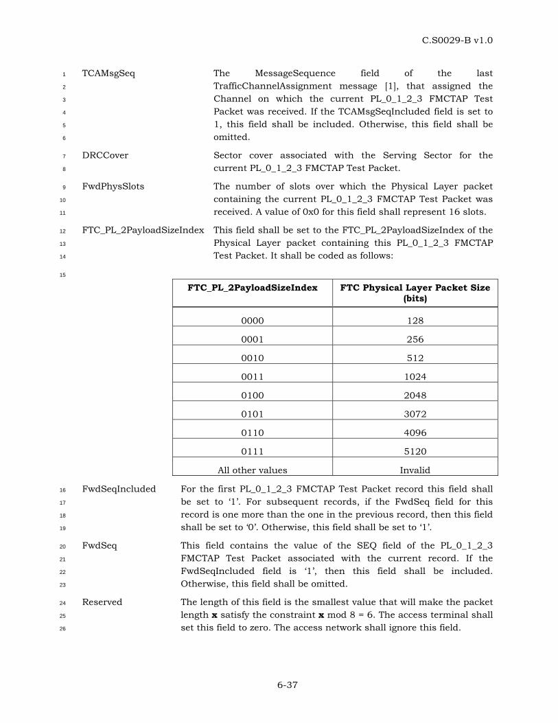
C.S0029-B v1.0
6-37
TCAMsgSeq The MessageSequence field of the last 1
TrafficChannelAssignment message [1], that assigned the 2
Channel on which the current PL_0_1_2_3 FMCTAP Test 3
Packet was received. If the TCAMsgSeqIncluded field is set to 4
1, this field shall be included. Otherwise, this field shall be 5
omitted. 6
DRCCover Sector cover associated with the Serving Sector for the 7
current PL_0_1_2_3 FMCTAP Test Packet. 8
FwdPhysSlots The number of slots over which the Physical Layer packet 9
containing the current PL_0_1_2_3 FMCTAP Test Packet was 10
received. A value of 0x0 for this field shall represent 16 slots. 11
FTC_PL_2PayloadSizeIndex This field shall be set to the FTC_PL_2PayloadSizeIndex of the 12
Physical Layer packet containing this PL_0_1_2_3 FMCTAP 13
Test Packet. It shall be coded as follows: 14
15
FTC_PL_2PayloadSizeIndex FTC Physical Layer Packet Size (bits)
0000 128
0001 256
0010 512
0011 1024
0100 2048
0101 3072
0110 4096
0111 5120
All other values Invalid
FwdSeqIncluded For the first PL_0_1_2_3 FMCTAP Test Packet record this field shall 16
be set to ‘1’. For subsequent records, if the FwdSeq field for this 17
record is one more than the one in the previous record, then this field 18
shall be set to ‘0’. Otherwise, this field shall be set to ‘1’. 19
FwdSeq This field contains the value of the SEQ field of the PL_0_1_2_3 20
FMCTAP Test Packet associated with the current record. If the 21
FwdSeqIncluded field is ‘1’, then this field shall be included. 22
Otherwise, this field shall be omitted. 23
Reserved The length of this field is the smallest value that will make the packet 24
length x satisfy the constraint x mod 8 = 6. The access terminal shall 25
set this field to zero. The access network shall ignore this field. 26
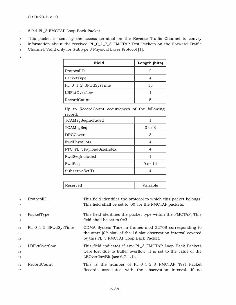
C.S0029-B v1.0
6-38
6.9.4 PL_3 FMCTAP Loop Back Packet 1
This packet is sent by the access terminal on the Reverse Traffic Channel to convey 2
information about the received PL_0_1_2_3 FMCTAP Test Packets on the Forward Traffic 3
Channel. Valid only for Subtype 3 Physical Layer Protocol [1]. 4
5
Field Length (bits)
ProtocolID 2
PacketType 4
PL_0_1_2_3FwdSysTime 15
LBPktOverflow 1
RecordCount 5
Up to RecordCount occurrences of the following record: TCAMsgSeqIncluded 1
TCAMsgSeq 0 or 8
DRCCover 3
FwdPhysSlots 4
FTC_PL_3PayloadSizeIndex 4
FwdSeqIncluded 1
FwdSeq 0 or 14
SubactiveSetID 4
Reserved Variable
ProtocolID This field identifies the protocol to which this packet belongs. 6
This field shall be set to ‘00’ for the FMCTAP packets. 7
PacketType This field identifies the packet type within the FMCTAP. This 8
field shall be set to 0x3. 9
PL_0_1_2_3FwdSysTime CDMA System Time in frames mod 32768 corresponding to 10
the start (0th slot) of the 16-slot observation interval covered 11
by this PL_3 FMCTAP Loop Back Packet. 12
LBPktOverflow This field indicates if any PL_3 FMCTAP Loop Back Packets 13
were lost due to buffer overflow. It is set to the value of the 14
LBOverflowBit (see 6.7.4.1). 15
RecordCount This is the number of PL_0_1_2_3 FMCTAP Test Packet 16
Records associated with the observation interval. If no 17
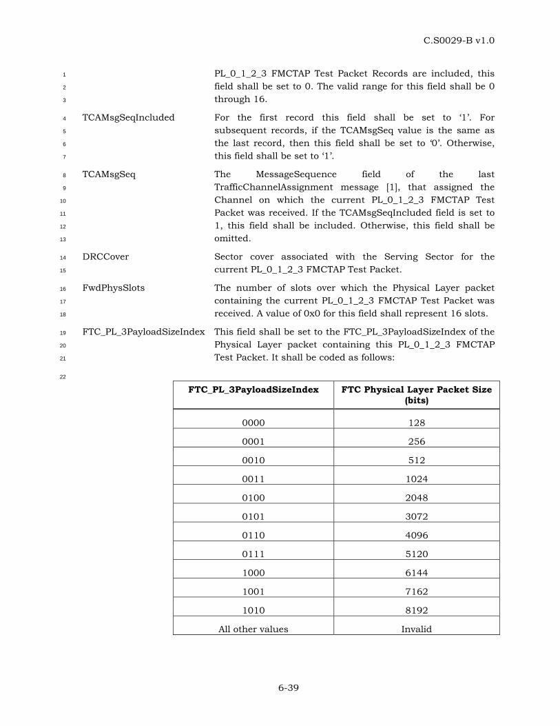
C.S0029-B v1.0
6-39
PL_0_1_2_3 FMCTAP Test Packet Records are included, this 1
field shall be set to 0. The valid range for this field shall be 0 2
through 16. 3
TCAMsgSeqIncluded For the first record this field shall be set to ‘1’. For 4
subsequent records, if the TCAMsgSeq value is the same as 5
the last record, then this field shall be set to ‘0’. Otherwise, 6
this field shall be set to ‘1’. 7
TCAMsgSeq The MessageSequence field of the last 8
TrafficChannelAssignment message [1], that assigned the 9
Channel on which the current PL_0_1_2_3 FMCTAP Test 10
Packet was received. If the TCAMsgSeqIncluded field is set to 11
1, this field shall be included. Otherwise, this field shall be 12
omitted. 13
DRCCover Sector cover associated with the Serving Sector for the 14
current PL_0_1_2_3 FMCTAP Test Packet. 15
FwdPhysSlots The number of slots over which the Physical Layer packet 16
containing the current PL_0_1_2_3 FMCTAP Test Packet was 17
received. A value of 0x0 for this field shall represent 16 slots. 18
FTC_PL_3PayloadSizeIndex This field shall be set to the FTC_PL_3PayloadSizeIndex of the 19
Physical Layer packet containing this PL_0_1_2_3 FMCTAP 20
Test Packet. It shall be coded as follows: 21
22
FTC_PL_3PayloadSizeIndex FTC Physical Layer Packet Size (bits)
0000 128
0001 256
0010 512
0011 1024
0100 2048
0101 3072
0110 4096
0111 5120
1000 6144
1001 7162
1010 8192
All other values Invalid
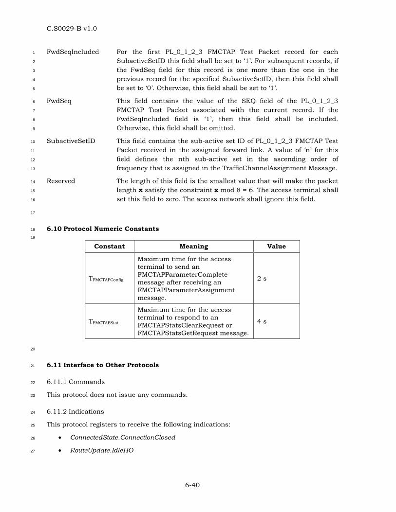
C.S0029-B v1.0
6-40
FwdSeqIncluded For the first PL_0_1_2_3 FMCTAP Test Packet record for each 1
SubactiveSetID this field shall be set to ‘1’. For subsequent records, if 2
the FwdSeq field for this record is one more than the one in the 3
previous record for the specified SubactiveSetID, then this field shall 4
be set to ‘0’. Otherwise, this field shall be set to ‘1’. 5
FwdSeq This field contains the value of the SEQ field of the PL_0_1_2_3 6
FMCTAP Test Packet associated with the current record. If the 7
FwdSeqIncluded field is ‘1’, then this field shall be included. 8
Otherwise, this field shall be omitted. 9
SubactiveSetID This field contains the sub-active set ID of PL_0_1_2_3 FMCTAP Test 10
Packet received in the assigned forward link. A value of ‘n’ for this 11
field defines the nth sub-active set in the ascending order of 12
frequency that is assigned in the TrafficChannelAssignment Message. 13
Reserved The length of this field is the smallest value that will make the packet 14
length x satisfy the constraint x mod 8 = 6. The access terminal shall 15
set this field to zero. The access network shall ignore this field. 16
17
6.10 Protocol Numeric Constants 18
19
Constant Meaning Value
TFMCTAPConfig
Maximum time for the access terminal to send an FMCTAPParameterComplete message after receiving an FMCTAPParameterAssignment message.
2 s
TFMCTAPStat
Maximum time for the access terminal to respond to an FMCTAPStatsClearRequest or FMCTAPStatsGetRequest message.
4 s
20
6.11 Interface to Other Protocols 21
6.11.1 Commands 22
This protocol does not issue any commands. 23
6.11.2 Indications 24
This protocol registers to receive the following indications: 25
• ConnectedState.ConnectionClosed 26
• RouteUpdate.IdleHO 27

C.S0029-B v1.0
6-41
• IdleState.ConnectionOpened 1

C.S0029-B v1.0
7-1
7 REVERSE MULTICARRIER TEST APPLICATION PROTOCOL (RMCTAP) 1
SPECIFICATION 2
7.1 Overview 3
The Reverse Multicarrier Test Application Protocol (RMCTAP) provides the procedures and 4
messages used by the access network and the access terminal to: 5
• Control RMCTAP test configurations at both the access terminal and the access 6
network. 7
• Generate PL_0_1 RMCTAP Test Packets and PL_0_1 RMCTAP Fill Packets at the 8
access terminal for transmission on the Reverse Traffic Channel, and process the 9
received packets at the access network. 10
• Transmit packets at configured Reverse Traffic Channel rates. Valid only for 11
Subtype 0 and 1 Physical Layer Protocols [1]. 12
• Generate PL_2 RMCTAP Test Packets at the access terminal for transmission on the 13
Reverse Traffic Channel, and process the received packets at the access network. 14
Includes support for multiple concurrent MAC flows as specified in Subtype 3 RTC 15
MAC Protocol [1]. 16
• Generate PL_3 RMCTAP Test Packets at the access terminal for transmission on the 17
Reverse Traffic Channel, and process the received packets at the access network. 18
Includes support for multiple concurrent reverse traffic channels as specified in 19
Multicarrier RTC MAC Protocol [1] 20
• Transmit packets at the configured Reverse Traffic Channel payload sizes. Valid 21
only for Subtype 2 and 3 Physical Layer Protocol [1]. 22
• Transmit packets at the configured Enhanced Access Channel rates. Valid only for 23
Subtype 1, 2 and 3 Physical Layer Protocols [1]. 24
• RMCTAP does not operate with Subtype 2 Reverse Traffic Channel MAC Protocol. 25
Throughout this section, the notation ‘PL_0_1’ refers to Subtype 0 or 1 Physical Layer 26
Protocol [1] applicability. The notation ‘PL_2’ refers to Subtype 2 Physical Layer Protocol [1] 27
applicability. The notation ‘PL_3’ refers to Subtype 3 Physical Layer Protocol [1] 28
applicability. 29
7.2 Data Encapsulation 30
In the transmit direction, the RMCTAP generates test packets and forwards them to the 31
stream layer. 32
In the receive direction the RMCTAP receives test packets from the stream layer and 33
processes them. 34
Figure 7.2-1illustrates the relationship between the RMCTAP packets and the Stream Layer 35
payload. 36
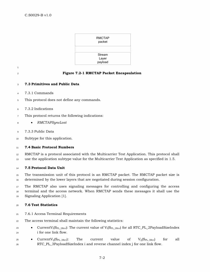
C.S0029-B v1.0
7-2
StreamLayer
payload
RMCTAP packet
1
Figure 7.2-1 RMCTAP Packet Encapsulation 2
7.3 Primitives and Public Data 3
7.3.1 Commands 4
This protocol does not define any commands. 5
7.3.2 Indications 6
This protocol returns the following indications: 7
• RMCTAPSyncLost 8
7.3.3 Public Data 9
Subtype for this application. 10
7.4 Basic Protocol Numbers 11
RMCTAP is a protocol associated with the Multicarrier Test Application. This protocol shall 12
use the application subtype value for the Multicarrier Test Application as specified in 1.5. 13
7.5 Protocol Data Unit 14
The transmission unit of this protocol is an RMCTAP packet. The RMCTAP packet size is 15
determined by the lower layers that are negotiated during session configuration. 16
The RMCTAP also uses signaling messages for controlling and configuring the access 17
terminal and the access network. When RMCTAP sends these messages it shall use the 18
Signaling Application [1]. 19
7.6 Test Statistics 20
7.6.1 Access Terminal Requirements 21
The access terminal shall maintain the following statistics: 22
• CurrentVi(SPL_2Rev): The current value of Vi(SPL_2Rev) for all RTC_PL_2PayloadSizeIndex 23
i for one link flow. 24
• CurrentVij(SPL_3Rev): The current value of Vij(SPL_3Rev) for all 25
RTC_PL_3PayloadSizeIndex i and reverse channel index j for one link flow. 26
C.S0029-B v1.0
7-3
• Stats_PL_2_3RevSysTime: CDMA System Time in sub-frames mod 549755813888 1
for one link flow corresponding to the slot boundary that begins the transmission of 2
the current RTC MAC Packet. 3
7.6.2 Access Network Requirements 4
The access network may maintain the following statistics: 5
• PL_0_1RTCMACPktSent[i]: An array whose (i+1)th element contains the number of 6
RTC MAC Packets that were sent by the access terminal at a rate corresponding to 7
the RTC_PL_0_1RateIndex i, as per Table 7.8.1.2-1. 8
• PL_2RTCMACPktSent[i]: An array whose (i+1)th element contains the number of RTC 9
MAC Packets that were sent by the access terminal at a payload size corresponding 10
to the RTC_PL_2PayloadSizeIndex i, as per Table 7.8.1.3-1. 11
• PL_3RTCMACPktSent[i,j]: An array whose (i+1)th element contains the number of 12
RTC MAC Packets that were sent by the access terminal at a payload size 13
corresponding to the RTC_PL_3PayloadSizeIndex i, as per Table 7.8.1.3-1 14
maintained for reverse channel index j. 15
• PL_0_1RTCMACPktRecd[i]: An array whose (i+1)th element contains the number of 16
RTC MAC Packets that were received by the access network at a rate corresponding 17
to the RTC_PL_0_1RateIndex i, as per Table 7.8.1.2-1. 18
• PL_2RTCMACPktRecd[i]: An array whose (i+1)th element contains the number of RTC 19
MAC Packets that were received by the access network at a rate corresponding to 20
the RTC_PL_2PayloadSizeIndex i, as per Table 7.8.1.3-1. 21
• PL_3RTCMACPktRecd[i,j]: An array whose (i+1)th element contains the number of 22
RTC MAC Packets that were received by the access network at a rate corresponding 23
to the RTC_PL_3PayloadSizeIndex i, as per Table 7.8.1.3-1 maintained for reverse 24
channel index j. 25
• PL_2TargetRTCMACPktRecd[i]: For Low Latency mode [1], an array whose (i+1)th 26
element contains the number of RTC MAC Packets that were received within 27
LoLatTerminationTargetPS [1] by the access network at a rate corresponding to 28
RTC_PL_2PayloadSizeIndex i, as per Table 7.8.1.3-1. For High Capacity mode [1], an 29
array whose (i+1)th element contains the number of RTC MAC Packets that were 30
received within HiCapTerminationTargetPS [1] by the access network at a rate 31
corresponding to RTC_PL_2PayloadSizeIndex i, as per Table 7.8.1.3-1. 32
• PL_3TargetRTCMACPktRecd[i,j]: For Low Latency mode [1], an array whose (i+1)th 33
element contains the number of RTC MAC Packets that were received within 34
LoLatTerminationTargetPS [1] by the access network at a rate corresponding to 35
RTC_PL_3PayloadSizeIndex i, as per Table 7.8.1.3-1 maintained for reverse channel 36
index j. For High Capacity mode [1], an array whose (i+1)th element contains the 37
number of RTC MAC Packets that were received within HiCapTerminationTargetPS 38
[1] by the access network at a rate corresponding to RTC_PL_3PayloadSizeIndex i, 39
as per Table 7.8.1.3-1 maintained for reverse channel index j. 40

C.S0029-B v1.0
7-4
• PL_2RMCTAPPhysPktSlots[i]: Array whose (i+1)th element contains the number of 1
slots over which the RTC MAC Packets were received by the access network 2
corresponding to the RTC_PL_2PayloadSizeIndex i, as per Table 7.8.1.3-1. 3
• PL_3RMCTAPPhysPktSlots[i,j]: Array whose (i+1)th element contains the number of 4
slots over which the RTC MAC Packets were received by the access network for 5
reverse channel index j corresponding to the RTC_PL_3PayloadSizeIndex i, as per 6
Table 7.8.1.3-1. 7
• PL_0_1RMCTAPTestTime: The duration of the RMCTAP test in frames. 8
• PL_2RMCTAPTestTime: The duration of the RMCTAP test in sub-frames. 9
• PL_3RMCTAPTestTime: The duration of the RMCTAP test in sub-frames. 10
• RTC_PL_2PayloadSizeIndex i(t): The RTC_PL_2PayloadSizeIndex i, as per Table 11
7.8.1.3-1, as a function of CDMA System Time in sub-frames, of an RTC MAC 12
Packet received by the access network. 13
• RTC_PL_3PayloadSizeIndex ij(t): The RTC_PL_3PayloadSizeIndex i, as per Table 14
7.8.1.3-1 maintained per active reverse channel index j, as a function of CDMA 15
System Time in sub-frames, of an RTC MAC Packet received by the access network. 16
• RTC_PL_2StreamLayerPayloadSize j(t): The RTC_PL_2StreamLayerPayloadSize j, as 17
a function of CDMA System Time in sub-frames, of a link flow j in an RTC MAC 18
Packet received by the access network. 19
• RTC_PL_3StreamLayerPayloadSize kj(t): The RTC_PL_3StreamLayerPayloadSize k 20
maintained per active reverse channel index j, as a function of CDMA System Time 21
in sub-frames, of a link flow k in an RTC MAC Packet received by the access 22
network. 23
7.7 Procedures 24
The RMCTAP is specified by the following procedures, which control and configure different 25
aspects of the Reverse Traffic Channel tests. 26
• Test Parameter Configuration: Procedures and messages for configuring test 27
parameters. 28
• Access Terminal Statistics Collection and Retrieval: Procedures and messages for 29
resetting the statistics being collected at the access terminal and for retrieving 30
them. 31
• RMCTAP Packet Transmission and Reception: Procedures for sending and receiving 32
PL_0_1 RMCTAP Test Packets and PL_0_1 RMCTAP Fill Packets on the Reverse 33
Traffic Channel. Procedures for sending and receiving PL_2 RMCTAP Test Packets 34
on the Reverse Traffic Channel. Procedures for sending and receiving PL_3 RMCTAP 35
Test Packets on the Reverse Traffic Channel. 36
37
C.S0029-B v1.0
7-5
7.7.1 Test Parameter Configuration 1
7.7.1.1 Access Terminal Requirements 2
When the protocol is instantiated, the access terminal shall execute the configuration 3
initialization procedure in 7.7.1.1.1. 4
When the protocol receives a ConnectedState.ConnectionClosed [1] indication, the access 5
terminal shall execute the configuration initialization procedure in 7.7.1.1.2. 6
If the access terminal receives an RMCTAPParameterAssignment message, it shall do the 7
following steps in sequence: 8
• Execute the configuration initialization procedure in 7.7.1.1.1. 9
• Execute the test parameter initialization procedure in 7.7.1.1.3. 10
• For Subtype 0 and 1 Physical Layer Protocols [1], if the message includes the 11
RMCTAPTestPktEnable parameter record, then the RMCTAP Test Packet mode is 12
enabled, and the value of the RMCTAPTestPktPersistence field is stored. The 13
RMCTAP Test Packet buffer is cleared and the RMCTAPTestPktOverflowBit is set to 14
‘0’ (see 7.7.3.1.1). 15
• For Subtype 2 and 3 Physical Layer Protocol [1], if the message includes the 16
RMCTAPTestPktEnable parameter record, then the RMCTAP Test Packet mode is 17
enabled, and the value of the RMCTAPTestPktPersistence field is stored. 18
• If the message includes the PacketRateMode parameter record, then the Configured 19
Packet Rate mode is enabled. The values of the MinRateIndex and MaxRateIndex 20
fields are stored (see 7.7.3.1.2). 21
• If the message includes the PacketPayloadSizeMode parameter record, then the 22
Configured Packet Payload Size mode is enabled. If the message includes the 23
PacketPayloadSizeModeMC parameter record, then the Configured Packet Payload 24
Size mode is enabled per active RL channel. The values of the MinPayloadSizeIndex 25
and MaxPayloadSizeIndex fields are stored (see 7.7.3.1.3). 26
• If the message includes the EnhancedAccessChannelRateMode parameter record, 27
then the Configured Enhanced Access Channel Rate mode is enabled. 28
• If the message includes the BurstPeriodMode parameter record, then the 29
Configured Burst Period mode is enabled. The values of the BurstPeriod and 30
LinkFlowID fields are stored (see 7.8.1.5). If the message includes the 31
BurstSizeMode parameter record, then the Configured Burst Size mode is enabled. 32
The values of the BurstSize and LinkFlowID fields are stored (see7.8.1.6). 33
• Send an RMCTAPParameterComplete message. The TransactionID field shall be set 34
to the same value as that received in the RMCTAPParameterAssignment message. 35
The RMCTAPParameterComplete message shall be sent within TRMCTAPConfig from 36
when the RMCTAPParameterAssignment message is received. 37
C.S0029-B v1.0
7-6
7.7.1.1.1 Access Terminal Configuration Initialization 1
When the protocol is instantiated or an RMCTAPParameterAssignment message is received, 2
the access terminal shall initialize the test configuration (per active RL channel for multi-3
carrier operation) as follows: 4
• The RMCTAP Test Packet mode is disabled. 5
• The Configured Packet Rate mode is disabled. 6
• The Configured Packet Payload Size mode is disabled. 7
• The Configured Enhanced Access Channel Rate mode is disabled. 8
• The Configured Burst Period mode is disabled. 9
• The Configured Burst Size mode is disabled. 10
7.7.1.1.2 Access Terminal Configuration for Closed or Lost Connection 11
When the protocol receives a ConnectedState.ConnectionClosed indication [1], the access 12
terminal shall initialize the test configuration (per active RL channel for multi-carrier 13
operation) as follows: 14
• If the RMCTAP Test Packet mode is enabled, and the value of the 15
RMCTAPTestPktPersistence field of the RMCTAPTestPktEnable parameter record in 16
the last received RMCTAPParameterAssignment message is ‘00’, then the RMCTAP 17
Test Packet mode is disabled. 18
• The Configured Packet Rate mode is disabled. 19
• The Configured Packet Payload Size mode is disabled. 20
• The Configured Enhanced Access Channel Rate mode is disabled, unless the access 21
terminal received an RMCTAPParameterAssignment message containing the 22
EnhancedAccessChannelRateMode parameter record while in connected state. 23
• The Configured Burst Period mode is disabled. 24
• The Configured Burst Size mode is disabled. 25
7.7.1.1.3 Access Terminal Test Parameter Initialization 26
For Subtype 0 and 1 Physical Layer Protocols [1], the access terminal shall set Vi(SPL_0_1Rev), 27
the 12-bit sequence number associated with RTC MAC Packets transmitted at the rate 28
corresponding to RTC_PL_0_1RateIndex i (Table 7.8.1.2-1), to zero, for all possible RTC 29
rates [1]. 30
For Subtype 2 Physical Layer Protocol [1], the access terminal shall set Vi(SPL_2Rev), the 32-31
bit sequence number associated with RTC MAC Packets transmitted using payload sizes 32
corresponding to RTC_PL_2PayloadSizeIndex i (Table 7.8.1.3-1) to zero for one link flow, for 33
all possible RTC payload sizes. 34
For Subtype 3 Physical Layer Protocol [1], the access terminal shall set Vij(SPL_3Rev), the 32-35
bit sequence number associated with RTC MAC Packets transmitted using payload sizes 36
C.S0029-B v1.0
7-7
corresponding to RTC_PL_3PayloadSizeIndex i (Table 7.8.1.3-1) and reverse channel index j 1
to zero for one link flow, for all possible RTC payload sizes. 2
7.7.1.2 Access Network Requirements 3
To change the test configuration the access network shall perform the following steps: 4
• Send an RMCTAPParameterAssignment message to the access terminal and wait for 5
an RMCTAPParameterComplete message containing the same TransactionID as that 6
in the RMCTAPParameterAssignment message. 7
• When the expected RMCTAPParameterComplete message is received, execute the 8
Test Statistics Initialization procedure in 7.7.1.2.1. 9
7.7.1.2.1 Access Network Test Statistics Initialization 10
The access network shall set the test statistics as follows: 11
• PL_0_1RTCMACPktSent[i] to zero for all possible i. 12
• PL_2RTCMACPktSent[i] to zero for all possible i. 13
• PL_3RTCMACPktSent[i,j] to zero for all possible i for reverse channel index j. 14
• PL_0_1RTCMACPktRecd[i] to zero for all possible i. 15
• PL_2RTCMACPktRecd[i] to zero for all possible i. 16
• PL_3RTCMACPktRecd[i,j] to zero for all possible i for reverse channel index j. 17
• PL_2RMCTAPPhysPktSlots[i] to zero for all possible i. 18
• PL_3RMCTAPPhysPktSlots[i,j] to zero for all possible i for reverse channel index j. 19
• PL_2TargetRTCMACPktRecd[i] to zero for all possible i. 20
• PL_3TargetRTCMACPktRecd[i,j] to zero for all possible i for reverse channel index j. 21
• PL_0_1RMCTAPTestTime to zero. 22
• PL_2RMCTAPTestTime to zero. 23
• PL_3RMCTAPTestTime to zero. 24
• RTC_PL_2PayloadSizeIndex i(t) to zero for all i. 25
• RTC_PL_2StreamLayerPayloadSize j(t) to zero for all j. 26
• RTC_PL_3PayloadSizeIndex ij(t) to zero for all i for each reverse channel index j. 27
• RTC_PL_3StreamLayerPayloadSize kj(t) to zero for all k for each reverse channel 28
index j. 29
7.7.2 Access Terminal Statistics Collection and Retrieval 30
7.7.2.1 Access Terminal Requirements 31
When the protocol is instantiated, the access terminal shall execute the Statistics 32
Initialization procedure in 7.7.2.1.1. 33
C.S0029-B v1.0
7-8
If the access terminal receives an RMCTAPStatsClearRequest message, the access terminal 1
shall 2
• execute the Statistics Initialization procedure as follows: 3
o If StatisticsRecordID is equal to 0x00, set PhysLaySubTyp2Seq_i for all 4
RTC_PL_2PayloadSizeIndex i and Stats_PL_2RevSysTime to zero. 5
o If StatisticsRecordID is equal to 0x01, set PhysLaySubTyp3Seq_ij for all 6
RTC_PL_3PayloadSizeIndex i for reverse channel index j and 7
Stats_PL_3RevSysTime to zero. 8
• send an RMCTAPStatsClearResponse message within TRMCTAPStat. 9
When the Air Link Management Protocol is in the Connected State and the RMCTAP Test 10
Packet mode is enabled 11
• PhysLaySubTyp2Seq_i for one link flow shall be incremented whenever an RTC MAC 12
Packet at a payload size with RTC_PL_2PayloadSizeIndex i (see Table 7.8.1.3-1) is 13
generated. 14
• PhysLaySubTyp3Seq_ij for one link flow for reverse channel index j shall be 15
incremented whenever an RTC MAC Packet at a payload size with 16
RTC_PL_3PayloadSizeIndex i (seeTable 7.8.1.3-1) is generated. 17
• Stats_PL_2RevSysTime shall reflect current CDMA System Time in subframes mod 18
549755813888 for one link flow corresponding to the slot boundary that begins the 19
transmission of the current RTC MAC Packet. 20
• Stats_PL_3RevSysTime shall reflect current CDMA System Time in subframes mod 21
549755813888 for one link flow corresponding to the slot boundary that begins the 22
transmission of the current RTC MAC Packet. 23
If the access terminal receives an RMCTAPStatsGetRequest message, it shall respond 24
within TRMCTAPStat with an RMCTAPStatsGetResponse containing the requested statistics 25
records. 26
7.7.2.1.1 Statistics Initialization 27
The access terminal shall set 28
• PhysLaySubTyp2Seq_i for one link flow to 0 for all RTC_PL_2PayloadSizeIndex i. 29
• Stats_PL_2RevSysTime for one link flow to 0. 30
• PhysLaySubTyp3Seq_ij for one link flow to 0 for all RTC_PL_3PayloadSizeIndex i and 31
for reverse channel index j. 32
• Stats_PL_3RevSysTime for one link flow to 0. 33
7.7.2.2 Access Network Requirements 34
To reset statistics collected at the access terminal, the access network shall send an 35
RMCTAPStatsClearRequest message and wait for an RMCTAPStatsClearResponse message 36
containing the same TransactionID as that in the RMCTAPStatsClearRequest message. 37
C.S0029-B v1.0
7-9
Reception of the expected RMCTAPStatsClearResponse message indicates that the test 1
statistics at the access terminal have been cleared. 2
To retrieve the statistics collected at the access terminal, the access network shall send an 3
RMCTAPStatsGetRequest message and wait for an RMCTAPStatsGetResponse message 4
containing the same TransactionID as that in the RMCTAPStatsGetRequest message. 5
7.7.3 PL_0_1 RMCTAP Packet, PL_2 RMCTAP Packet and PL_3 RMCTAP Packet 6
Transmission and Reception 7
7.7.3.1 Access Terminal Requirements 8
7.7.3.1.1 Generation and Transmission 9
For Subtype 0 and 1 Physical Layer Protocols [1], if the RMCTAP Test Packet mode is 10
enabled, the access terminal shall generate a PL_0_1 RMCTAP Test Packet at the beginning 11
of every 16-slot interval aligned to the CDMA System Time [1] in frames. 12
For Subtype 2 Physical Layer Protocol [1], if the RMCTAP Test Packet mode is enabled, the 13
access terminal shall generate a PL_2 RMCTAP Test Packet for a link flow, as appropriate, 14
for every 4-slot interval aligned to the CDMA System Time that begins a new transmission 15
of an RTC MAC Packet containing a PL_2 RMCTAP Test Packet. The access terminal shall 16
increment the sequence number Vi(SPL_2Rev) for every 4-slot interval aligned to the CDMA 17
System Time that begins a new transmission of an RTC MAC Packet. 18
For Subtype 3 Physical Layer Protocol [1], if the RMCTAP Test Packet mode is enabled, the 19
access terminal shall generate a PL_3 RMCTAP Test Packet for a link flow for each active 20
RL channel, as appropriate, for every 4-slot interval aligned to the CDMA System Time that 21
begins a new transmission of an RTC MAC Packet containing a PL_3 RMCTAP Test Packet. 22
The access terminal shall increment the sequence number Vij(SPL_3Rev) for every 4-slot 23
interval aligned to the CDMA System Time that begins a new transmission of an RTC MAC 24
Packet. The sequence number Vij(SPL_3Rev) will be independently generated for each active RL 25
channel assigned in the TrafficChannelAssignment Message. 26
The access terminal shall obey the following rules: 27
• The PL_0_1 RMCTAP Test Packets, PL_2 RMCTAP Test Packets and PL_3 RMCTAP 28
Test Packets shall be generated only in the Connected State of the Air Link 29
Management Protocol. 30
• The information contained in the PL_0_1 RMCTAP Test Packet (see 7.9.1) shall cover 31
RTC MAC Packets transmitted up to, but not including, the time instant of 32
generation. 33
• The information contained in the PL_2 RMCTAP Test Packet and PL_3 RMCTAP Test 34
Packets (see 7.9.3 and 7.9.4) shall cover the current RTC MAC Packet. 35
• The access terminal shall assign a transmission priority of 55 to PL_0_1 RMCTAP 36
Test Packets, PL_2 RMCTAP Test Packets and PL_3 RMCTAP Test Packets. 37
• For Subtype 0 and 1 Physical Layer Protocols [1], the transmission rate for the RTC 38
MAC Packet shall be determined as specified in 7.7.3.1.2. 39
C.S0029-B v1.0
7-10
• For Subtype 2 and 3 Physical Layer Protocol [1], the payload size of the RTC MAC 1
Packet shall be determined as specified in 7.7.3.1.3. 2
• The access terminal shall queue the generated PL_0_1 RMCTAP Test Packets. The 3
access terminal shall provide buffering for at least 16 PL_0_1 RMCTAP Test Packets. 4
The RMCTAPTestPktOverflowBit indicates if any PL_0_1 RMCTAP Test Packets have 5
been lost due to lack of buffer space. When a packet is lost due to lack of buffer 6
space, the RMCTAPTestPktOverflowBit shall be set to ‘1’. 7
The access terminal shall follow the following rules for transmitting a PL_0_1 RMCTAP Test 8
Packet, PL_2 RMCTAP Test Packet and PL_3 RMCTAP Test Packet: 9
• The access terminal shall transmit the queued PL_0_1 RMCTAP Test Packets in the 10
Connected State of the Air Link Management Protocol [1]. 11
• The access terminal shall transmit the PL_2 RMCTAP Test Packets and PL_3 12
RMCTAP Test Packets in the Connected State of the Air Link Management Protocol 13
[1]. 14
• If the Configured Packet Rate mode is enabled, the access terminal shall transmit a 15
PL_0_1 RMCTAP Fill Packet of the size necessary for the RTC MAC Packet 16
containing the PL_0_1 RMCTAP Test Packet at the selected rate. The access 17
terminal shall set the priority of the PL_0_1 RMCTAP Fill Packet to 255. 18
• When the access terminal transmits an RTC MAC Packet at a rate with 19
RTC_PL_0_1RateIndex i (Table 7.8.1.2-1), it shall increment the sequence number 20
Vi(SPL_0_1Rev). 21
• When the access terminal transmits an RTC MAC Packet with a payload size with 22
RTC_PL_2PayloadSizeIndex i (Table 7.8.1.3-1), it shall increment the sequence 23
number Vi(SPL_2Rev) for one link flow. 24
• When the access terminal transmits an RTC MAC Packet with a payload size with 25
RTC_PL_3PayloadSizeIndex i for reverse channel index j (Table 7.8.1.3-1), it shall 26
increment the sequence number Vij(SPL_3Rev) for one link flow 27
• For each PL_2 RMCTAP Test Packet transmitted, the access terminal shall reduce 28
the BurstSize (see 7.8.1.6) for a link flow by the RTC_PL_2StreamLayerPayloadSize 29
(see 7.6.2) provided that BurstSize was not initially set to full buffer (0xFFFF). 30
When the BurstPeriod (see 7.8.1.5) has elapsed for a link flow, the access terminal 31
shall reset the BurstSize to its initial value if the BurstSize has been reduced to zero 32
octets during the BurstPeriod. Otherwise, the access terminal shall reset the 33
BurstSize to its initial value plus the number of BurstSize octets remaining after the 34
BurstPeriod has elapsed. In the event that the BurstSize becomes equal to or 35
greater than full buffer (0xFFFF), the access terminal shall set the BurstSize to full 36
buffer. 37
• If multiple PL_0_1 RMCTAP Test Packets are included in an RTC MAC Packet, the 38
PL_0_1 RMCTAP Test Packets shall be ordered so that a packet corresponding to an 39
earlier time appears first. 40
C.S0029-B v1.0
7-11
• If the access terminal receives a ConnectedState.ConnectionClosed [1] indication, 1
and it has queued PL_0_1 RMCTAP Test Packets, it shall not attempt to establish a 2
connection to transmit the packets. 3
7.7.3.1.2 Rate Selection 4
If the Configured Packet Rate mode is enabled, the access terminal shall obey the following 5
rules to select a Reverse Traffic Channel rate; otherwise, the access terminal shall select a 6
rate as per the Reverse Traffic Channel MAC Protocol [1]. 7
The access terminal shall maintain the following variables: 8
• MinRate: Value of the MinRateIndex field received in the PacketRateMode parameter 9
record of the RMCTAPParameterAssignment message. 10
• MaxRate: Value of the MaxRateIndex field received in the PacketRateMode 11
parameter record of the RMCTAPParameterAssignment message. 12
• MACMaxRate: RTC_PL_0_1RateIndex as per Table 7.8.1.2-1 corresponding to the 13
maximum rate allowed by the Reverse Traffic Channel MAC protocol [1]. 14
• TargetRate: RTC_PL_0_1RateIndex corresponding to the desired rate. 15
• SelectedRate: RTC_PL_0_1RateIndex corresponding to the selected rate. 16
For the first RTC MAC Packet following the start of the test, the access terminal shall set 17
TargetRate to MinRate, and the SelectedRate = Min (TargetRate,MACMaxRate). For all the 18
subsequent RTC MAC Packets, the access terminal shall choose the rate as follows: 19
TargetRate = TargetRate + 1; 20
If (TargetRate > MaxRate) 21
TargetRate = MinRate; 22
SelectedRate = Min (TargetRate, MACMaxRate); 23
If the Configured Enhanced Access Channel Rate Mode is enabled, the access terminal 24
shall obey the following rules to select an Access Channel rate as follows: 25
Min (EnhancedAccessChannelRateIndex, SectorAccessMaxRate) 26
Otherwise, the access terminal shall select a rate as per the Enhanced Access Channel 27
MAC Protocol [1]. 28
7.7.3.1.3 Payload Size Selection 29
If the Configured Packet Payload Size mode is enabled, the access terminal shall obey the 30
following rules to select a Reverse Traffic Channel payload size; otherwise, the access 31
terminal shall select a payload size as per the Subtype 3 Reverse Traffic Channel MAC 32
Protocol for PL2_RMCTAP Test Packet and per the Multicarrier Reverse Traffic Channel 33
MAC Protocol for PL3_RMCTAP Test Packet [1]. 34
The access terminal shall maintain the following variables: 35
C.S0029-B v1.0
7-12
• MinPayloadSize: Value of the MinPayloadSizeIndex field received in the 1
PacketPayloadSizeMode parameter record of the RMCTAPParameterAssignment 2
message. 3
• MaxPayloadSize: Value of the MaxPayloadSizeIndex field received in the 4
PacketPayloadSizeMode parameter record of the RMCTAPParameterAssignment 5
message. 6
• MACMaxPayloadSize: RTC_PL_2PayloadSizeIndex or RTC_PL_3PayloadSizeIndex as 7
per Table 7.8.1.3-1 corresponding to the maximum payload size so that Condition 8
1, 2, 3, and 5 in Section 9.12.6.1.6.1.1.2 of the Subtype 3 Reverse Traffic Channel 9
MAC Protocol or Section 9.13.6.1.6.1.1.2 in Multicarrier Reverse Traffic Channel 10
MAC Protocol [1] are satisfied. 11
• TargetPayloadSize: RTC_PL_2PayloadSizeIndex or RTC_PL_3PayloadSizeIndex 12
corresponding to the desired payload size. 13
• SelectedPayloadSize: RTC_PL_2PayloadSizeIndex or RTC_PL_3PayloadSizeIndex 14
corresponding to the selected payload size. 15
For the first RTC MAC Packet following the start of the test, the access terminal shall set 16
TargetPayloadSize to MinPayloadSize, and the SelectedPayloadSize = Min 17
(TargetPayloadSize, MACMaxPayloadSize). For all the subsequent RTC MAC Packets, the 18
access terminal shall choose the payload size as follows: 19
TargetPayloadSize = TargetPayloadSize + 1; 20
If (TargetPayloadSize > MaxPayloadSize) 21
TargetPayloadSize = MinPayloadSize; 22
SelectedPayloadSize = Min (TargetPayloadSize, MACMaxPayloadSize); 23
7.7.3.2 Access Network Requirements 24
The access network shall maintain the following variables: 25
• PL_0_1V(RRMCTAP): A 15-bit variable that corresponds to the sequence number of the 26
next expected PL_0_1 RMCTAP Test Packet. 27
• PL_2V(RRMCTAP): A 17-bit variable that corresponds to the sequence number of the 28
next expected PL_2 RMCTAP Test Packet for each link flow. 29
• PL_3Vj(RRMCTAP): A 17-bit variable that corresponds to the sequence number of the 30
next expected PL_3 RMCTAP Test Packet for each link flow for reverse channel index 31
j. 32
• PL_0_1X[i]: A 12-bit variable that represents the sequence number corresponding to 33
the next expected RTC MAC Packet transmitted at a rate associated with 34
RTC_PL_0_1RateIndex i as per Table 7.8.1.2-1. 35
• PL_2X[i]: A 32-bit variable for each link flow that represents the sequence number 36
corresponding to the next expected RTC MAC Packet transmitted with a payload 37
size associated with RTC_PL_2PayloadSizeIndex i as per Table 7.8.1.3-1. 38
C.S0029-B v1.0
7-13
• PL_3X[i,j]: A 32-bit variable for each link flow that represents the sequence number 1
corresponding to the next expected RTC MAC Packet transmitted with a payload 2
size associated with RTC_PL_3PayloadSizeIndex i as per Table 7.8.1.3-1 for reverse 3
channel index j. 4
When a PL_0_1 RMCTAP Test Packet arrives for the first time, following the receipt of an 5
RMCTAPParameterComplete message, the access network shall 6
• Set PL_0_1V(RRMCTAP) to the value of the PL_0_1RevSysTime field of the PL_0_1 7
RMCTAP Test Packet. 8
• Set PL_0_1X[i] to the value of the (Seq_i field of the PL_0_1 RMCTAP Test Packet) + 1 9
for all possible values of i. 10
When a PL_2 RMCTAP Test Packet arrives for the first time, following the receipt of an 11
RMCTAPParameterComplete message, the access network shall 12
• Set PL_2V(RRMCTAP) to the value of the PL_2RevSysTime field of the PL_2 RMCTAP 13
Test Packet for each flow. 14
• Set PL_2X[i] to the value of the (PhysLaySubTyp2Seq field corresponding to the 15
PayloadSizeIndex field of the PL_2 RMCTAP Test Packet) + 1 for each link flow. 16
When a PL_3 RMCTAP Test Packet arrives for the first time, following the receipt of an 17
RMCTAPParameterComplete message, the access network shall 18
• Set PL_3Vj(RRMCTAP) to the value of the PL_3RevSysTime field of the PL_3 RMCTAP 19
Test Packet for each flow. 20
• Set PL_3X[i,j] to the value of the (PhysLaySubTyp3Seq field corresponding to the 21
PayloadSizeIndex field of the PL_3 RMCTAP Test Packet) + 1 for each link flow for 22
reverse channel index j. 23
All operations and comparisons performed on packet sequence numbers shall be carried 24
out in unsigned modulo 2S arithmetic, where S is the number of bits used to represent the 25
sequence number. For a packet sequence number x, the numbers in the range [x+1, x + 2S-26
1 –1] are considered greater than x and numbers in the range [x – 2S-1, x-1] are considered 27
smaller than x. 28
For Subtype 0 and 1 Physical Layer Protocols [1], for each RTC MAC Packet received at a 29
rate corresponding to RTC_PL_0_1RateIndex k, PL_0_1RTCMACPktRecd[k] shall be 30
incremented by 1. 31
For Subtype 2 Physical Layer Protocol [1], for each RTC MAC Packet received with a 32
payload size corresponding to RTC_PL_2PayloadSizeIndex k, PL_2RTCMACPktRecd[k] shall 33
be incremented by 1. 34
For Subtype 3 Physical Layer Protocol [1], for each RTC MAC Packet received with a 35
payload size corresponding to RTC_PL_3PayloadSizeIndex k, PL_3RTCMACPktRecd[k,j] 36
shall be incremented by 1 for reverse channel index j. 37
For Subtype 2 Physical Layer Protocol and Low Latency mode [1], for each RTC MAC Packet 38
received within LotLatTerminationTargetPS [1] with a payload size corresponding to 39
RTC_PL2PayloadSizeIndex k, PL_2TargetRTCMACPktRecd[k] shall be incremented by 1. For 40
C.S0029-B v1.0
7-14
Subtype 2 Physical Layer Protocol and High Capacity mode [1], for each RTC MAC Packet 1
received within HiCapTerminationTargetPS [1] with a payload size corresponding to 2
RTC_PL2PayloadSizeIndex k, PL_2TargetRTCMACPktRecd[k] shall be incremented by 1. 3
For Subtype 3 Physical Layer Protocol and Low Latency mode [1], for each RTC MAC 4
Packet received within LotLatTerminationTargetPS [1] with a payload size corresponding to 5
RTC_PL3PayloadSizeIndex k, PL_3TargetRTCMACPktRecd[k,j] shall be incremented by 1 for 6
reverse channel index j. For Subtype 3 Physical Layer Protocol and High Capacity mode [1], 7
for each RTC MAC Packet received within HiCapTerminationTargetPS [1] with a payload 8
size corresponding to RTC_PL3PayloadSizeIndex k, PL_3TargetRTCMACPktRecd[k,j] shall 9
be incremented by 1 for reverse channel index j. 10
For each PL_0_1 RMCTAP Test Packet received, the access network shall perform the 11
following procedure using the value of the PL_0_1RevSysTime field: 12
• If PL_0_1RevSysTime >= PL_0_1V(RRMCTAP), 13
o PL_0_1RMCTAPTestTime shall be incremented by PL_0_1RevSysTime – 14
PL_0_1V(RRMCTAP) + 1. 15
o PL_0_1V(RRMCTAP) is set to PL_0_1RevSysTime + 1. 16
• If PL_0_1RevSysTime < PL_0_1V(RRMCTAP), then the access network shall generate an 17
RMCTAPSyncLost indication. 18
The fields of a received PL_0_1 RMCTAP Test Packet shall be processed using the values of 19
the Seq_i fields for all possible values of i as follows: 20
• PL_0_1RTCMACPktSent[i] shall be incremented by Seq_i – PL_0_1X[i] + 1. 21
• PL_0_1X[i] shall be set to Seq_i + 1. 22
For each PL_2 RMCTAP Test Packet received, the access network shall perform the 23
following procedure using the value of the PL_2RevSysTime field: 24
• If PL_2RevSysTime >= PL_2V(RRMCTAP), 25
o PL_2RMCTAPTestTime shall be incremented by PL_2RevSysTime – 26
PL_2V(RRMCTAP) + 1. 27
o PL_2V(RRMCTAP) is set to PL_2RevSysTime + 1. 28
• If PL_2RevSysTime + 9 < PL_2V(RRMCTAP), then the access network shall generate an 29
RMCTAPSyncLost indication. 30
For each PL_3 RMCTAP Test Packet received, the access network shall perform the 31
following procedure using the value of the PL_3RevSysTime field for reverse channel index 32
j: 33
• If PL_3RevSysTime >= PL_3Vj(RRMCTAP), 34
o PL_3RMCTAPTestTime shall be incremented by PL_3RevSysTime – 35
PL_3Vj(RRMCTAP) + 1. 36
o PL_3Vj(RRMCTAP) is set to PL_3RevSysTime + 1. 37
C.S0029-B v1.0
7-15
• If PL_3RevSysTime + 9 < PL_3Vj(RRMCTAP), then the access network shall generate an 1
RMCTAPSyncLost indication. 2
The fields of a received PL_2 RMCTAP Test Packet for each link flow shall be processed 3
using the values of the PhysLaySubTyp2Seq field and RTC_PL_2PayloadSizeIndex field for 4
all possible values of i as follows if PhysLaySubTyp2Seq_i > PL_2X[i]: 5
• PL_2RTCMACPktSent[i] shall be incremented by PhysLaySubTyp2Seq_i – PL_2X[i] + 6
1. 7
• PL_2X[i] shall be set to PhysLaySubTyp2Seq_i + 1. 8
• PL_2RMCTAPPhysPktSlots[i] shall be incremented by the number of slots that was 9
needed to receive this PL_2 RMCTAP Test Packet. 10
The fields of a received PL_3 RMCTAP Test Packet for each link flow over each active RL 11
carrier shall be processed using the values of the PhysLaySubTyp3Seq field and 12
RTC_PL_3PayloadSizeIndex field for all possible values of i and for reverse channel index j 13
as follows if PhysLaySubTyp3Seq_ij > PL_3X[i,j]: 14
• PL_3RTCMACPktSent[i,j] shall be incremented by PhysLaySubTyp3Seq_ij – 15
PL_3X[i,j] + 1. 16
• PL_3X[i,j] shall be set to PhysLaySubTyp3Seq_ij + 1. 17
• PL_3RMCTAPPhysPktSlots[i,j] shall be incremented by the number of slots that was 18
needed to receive this PL_3 RMCTAP Test Packet. 19
For Subtype 2 and 3 Physical Layer Protocol [1], for each RTC MAC Packet received with a 20
payload size corresponding to RTC_PL_2PayloadSizeIndex k or RTC_PL_3PayloadSizeIndex 21
k, RTC_PL_2PayloadSizeIndex k or RTC_PL_3PayloadSizeIndex k may be logged as a 22
function of CDMA System Time in sub-frames. 23
For Subtype 2 and 3 Physical Layer Protocol [1], for each RTC MAC Packet received with a 24
payload size corresponding to RTC_PL_2PayloadSizeIndex k or RTC_PL_3PayloadSizeIndex 25
k, RTC_PL_2StreamLayer PayloadSizeIndex j of a link flow j or RTC_PL_3StreamLayer 26
PayloadSizeIndex j of a link flow j contained in the received RTC MAC Packet may be logged 27
as a function of CDMA System Time in sub-frames. 28
7.7.4 Multicarrier RL management (for Physical Layer Subtype 3 only) 29
7.7.4.1 Access Terminal Requirements 30
If the list of reverse link channels included in the TrafficChannelAssignment Message is 31
changed, then the access terminal shall perform procedure in 7.7.1.1.2 and parameter 32
initialization procedure in 7.7.1.1.3. 33
7.7.4.2 Access Network Requirements 34
For subsequent TrafficChannelAssignment Messages generated after the first 35
TrafficChannelAssignment Message by the access network, if the list of reverse link 36
channels included in the TrafficChannelAssignment Message is changed, then the access 37
network shall perform access network initialization procedure in 7.7.1.2.1. 38
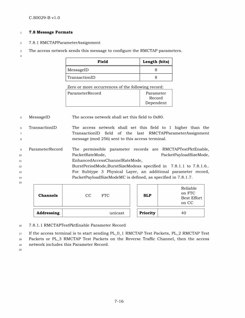
C.S0029-B v1.0
7-16
7.8 Message Formats 1
7.8.1 RMCTAPParameterAssignment 2
The access network sends this message to configure the RMCTAP parameters. 3
4
Field Length (bits)
MessageID 8
TransactionID 8
Zero or more occurrences of the following record: ParameterRecord Parameter
Record Dependent
MessageID The access network shall set this field to 0x80. 5
TransactionID The access network shall set this field to 1 higher than the 6
TransactionID field of the last RMCTAPParameterAssignment 7
message (mod 256) sent to this access terminal. 8
ParameterRecord The permissible parameter records are RMCTAPTestPktEnable, 9
PacketRateMode, PacketPayloadSizeMode, 10
EnhancedAccessChannelRateMode, 11
BurstPeriodMode,BurstSizeModeas specified in 7.8.1.1 to 7.8.1.6.. 12
For Subtype 3 Physical Layer, an additional parameter record, 13
PacketPayloadSizeModeMC is defined, as specified in 7.8.1.7. 14
15
Channels CC FTC SLP
Reliable on FTC Best Effort on CC
Addressing unicast Priority 40
7.8.1.1 RMCTAPTestPktEnable Parameter Record 16
If the access terminal is to start sending PL_0_1 RMCTAP Test Packets, PL_2 RMCTAP Test 17
Packets or PL_3 RMCTAP Test Packets on the Reverse Traffic Channel, then the access 18
network includes this Parameter Record. 19
20
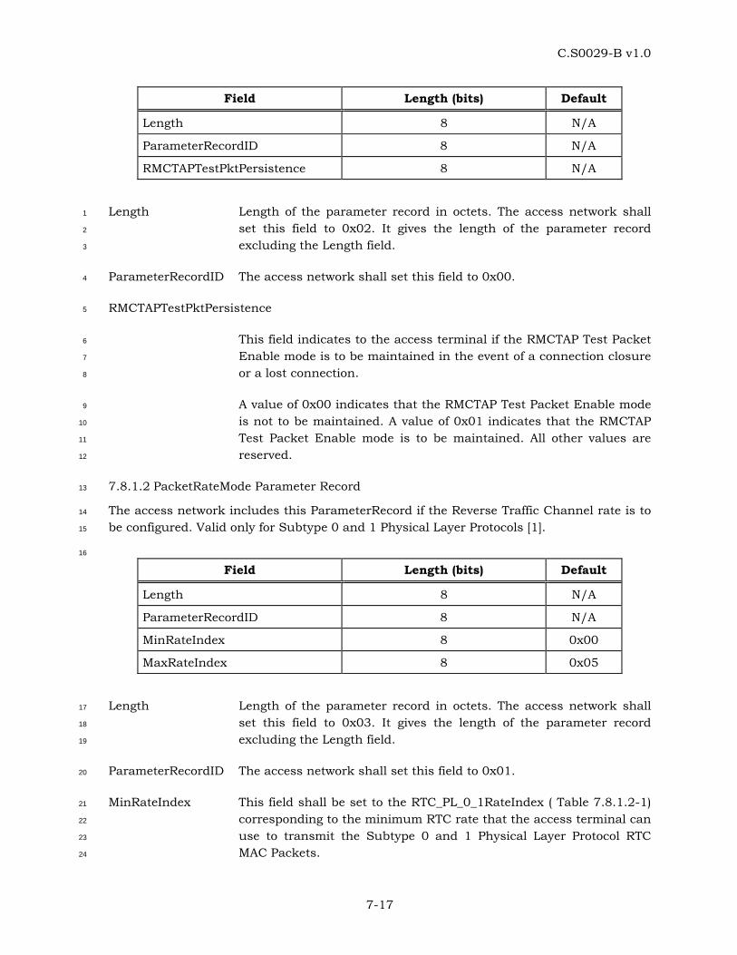
C.S0029-B v1.0
7-17
Field Length (bits) Default
Length 8 N/A
ParameterRecordID 8 N/A
RMCTAPTestPktPersistence 8 N/A
Length Length of the parameter record in octets. The access network shall 1
set this field to 0x02. It gives the length of the parameter record 2
excluding the Length field. 3
ParameterRecordID The access network shall set this field to 0x00. 4
RMCTAPTestPktPersistence 5
This field indicates to the access terminal if the RMCTAP Test Packet 6
Enable mode is to be maintained in the event of a connection closure 7
or a lost connection. 8
A value of 0x00 indicates that the RMCTAP Test Packet Enable mode 9
is not to be maintained. A value of 0x01 indicates that the RMCTAP 10
Test Packet Enable mode is to be maintained. All other values are 11
reserved. 12
7.8.1.2 PacketRateMode Parameter Record 13
The access network includes this ParameterRecord if the Reverse Traffic Channel rate is to 14
be configured. Valid only for Subtype 0 and 1 Physical Layer Protocols [1]. 15
16
Field Length (bits) Default
Length 8 N/A
ParameterRecordID 8 N/A
MinRateIndex 8 0x00
MaxRateIndex 8 0x05
Length Length of the parameter record in octets. The access network shall 17
set this field to 0x03. It gives the length of the parameter record 18
excluding the Length field. 19
ParameterRecordID The access network shall set this field to 0x01. 20
MinRateIndex This field shall be set to the RTC_PL_0_1RateIndex ( Table 7.8.1.2-1) 21
corresponding to the minimum RTC rate that the access terminal can 22
use to transmit the Subtype 0 and 1 Physical Layer Protocol RTC 23
MAC Packets. 24
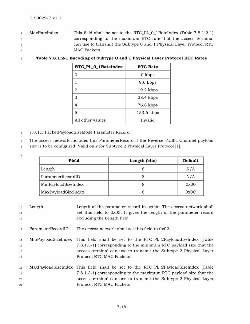
C.S0029-B v1.0
7-18
MaxRateIndex This field shall be set to the RTC_PL_0_1RateIndex (Table 7.8.1.2-1) 1
corresponding to the maximum RTC rate that the access terminal 2
can use to transmit the Subtype 0 and 1 Physical Layer Protocol RTC 3
MAC Packets. 4
Table 7.8.1.2-1 Encoding of Subtype 0 and 1 Physical Layer Protocol RTC Rates 5
RTC_PL_0_1RateIndex RTC Rate
0 0 kbps
1 9.6 kbps
2 19.2 kbps
3 38.4 kbps
4 76.8 kbps
5 153.6 kbps
All other values Invalid
7.8.1.3 PacketPayloadSizeMode Parameter Record 6
The access network includes this ParameterRecord if the Reverse Traffic Channel payload 7
size is to be configured. Valid only for Subtype 2 Physical Layer Protocol [1]. 8
9
Field Length (bits) Default
Length 8 N/A
ParameterRecordID 8 N/A
MinPayloadSizeIndex 8 0x00
MaxPayloadSizeIndex 8 0x0C
Length Length of the parameter record in octets. The access network shall 10
set this field to 0x03. It gives the length of the parameter record 11
excluding the Length field. 12
ParameterRecordID The access network shall set this field to 0x02. 13
MinPayloadSizeIndex This field shall be set to the RTC_PL_2PayloadSizeIndex (Table 14
7.8.1.3-1) corresponding to the minimum RTC payload size that the 15
access terminal can use to transmit the Subtype 2 Physical Layer 16
Protocol RTC MAC Packets. 17
MaxPayloadSizeIndex This field shall be set to the RTC_PL_2PayloadSizeIndex (Table 18
7.8.1.3-1) corresponding to the maximum RTC payload size that the 19
access terminal can use to transmit the Subtype 2 Physical Layer 20
Protocol RTC MAC Packets. 21
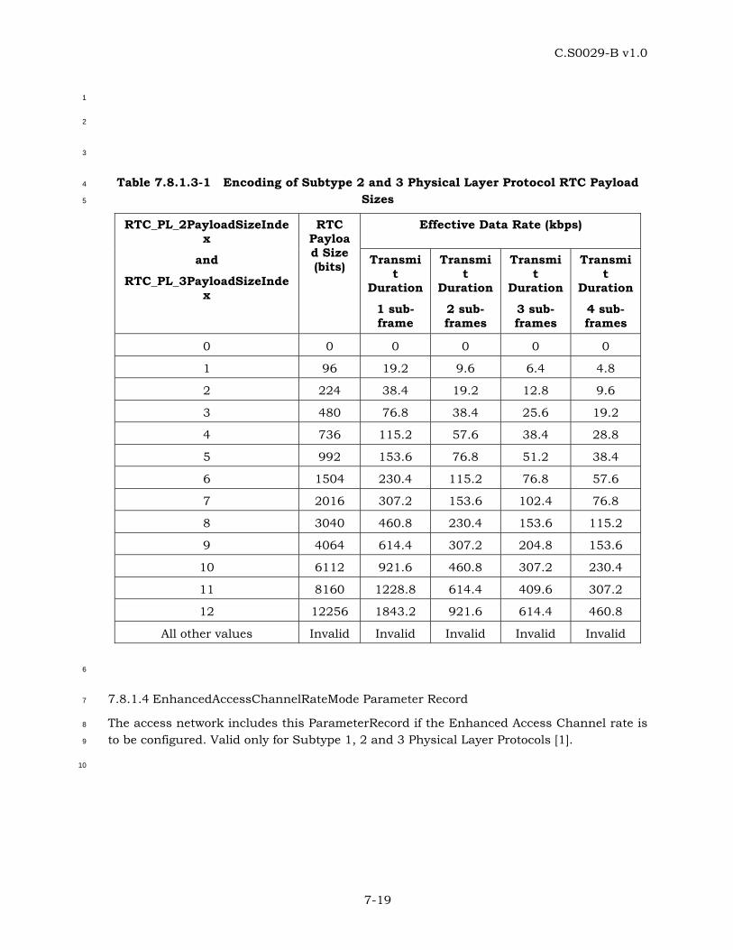
C.S0029-B v1.0
7-19
1
2
3
Table 7.8.1.3-1 Encoding of Subtype 2 and 3 Physical Layer Protocol RTC Payload 4
Sizes 5
Effective Data Rate (kbps) RTC_PL_2PayloadSizeIndex
and
RTC_PL_3PayloadSizeIndex
RTC Payload Size (bits) Transmi
t Duration
1 sub-frame
Transmit
Duration
2 sub-frames
Transmit
Duration
3 sub-frames
Transmit
Duration
4 sub-frames
0 0 0 0 0 0
1 96 19.2 9.6 6.4 4.8
2 224 38.4 19.2 12.8 9.6
3 480 76.8 38.4 25.6 19.2
4 736 115.2 57.6 38.4 28.8
5 992 153.6 76.8 51.2 38.4
6 1504 230.4 115.2 76.8 57.6
7 2016 307.2 153.6 102.4 76.8
8 3040 460.8 230.4 153.6 115.2
9 4064 614.4 307.2 204.8 153.6
10 6112 921.6 460.8 307.2 230.4
11 8160 1228.8 614.4 409.6 307.2
12 12256 1843.2 921.6 614.4 460.8
All other values Invalid Invalid Invalid Invalid Invalid
6
7.8.1.4 EnhancedAccessChannelRateMode Parameter Record 7
The access network includes this ParameterRecord if the Enhanced Access Channel rate is 8
to be configured. Valid only for Subtype 1, 2 and 3 Physical Layer Protocols [1]. 9
10
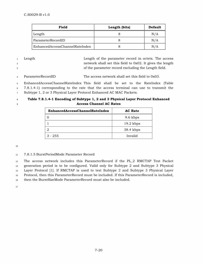
C.S0029-B v1.0
7-20
Field Length (bits) Default
Length 8 N/A
ParameterRecordID 8 N/A
EnhancedAccessChannelRateIndex 8 N/A
Length Length of the parameter record in octets. The access 1
network shall set this field to 0x02. It gives the length 2
of the parameter record excluding the Length field. 3
ParameterRecordID The access network shall set this field to 0x03. 4
EnhancedAccessChannelRateIndex This field shall be set to the RateIndex (Table 5
7.8.1.4-1) corresponding to the rate that the access terminal can use to transmit the 6
Subtype 1, 2 or 3 Physical Layer Protocol Enhanced AC MAC Packets. 7
Table 7.8.1.4-1 Encoding of Subtype 1, 2 and 3 Physical Layer Protocol Enhanced 8
Access Channel AC Rates 9
EnhancedAccessChannelRateIndex AC Rate
0 9.6 kbps
1 19.2 kbps
2 38.4 kbps
3 - 255 Invalid
10
7.8.1.5 BurstPeriodMode Parameter Record 11
The access network includes this ParameterRecord if the PL_2 RMCTAP Test Packet 12
generation period is to be configured. Valid only for Subtype 2 and Subtype 3 Physical 13
Layer Protocol [1]. If RMCTAP is used to test Subtype 2 and Subtype 3 Physical Layer 14
Protocol, then this ParameterRecord must be included. If this ParameterRecord is included, 15
then the BurstSizeMode ParameterRecord must also be included. 16
17
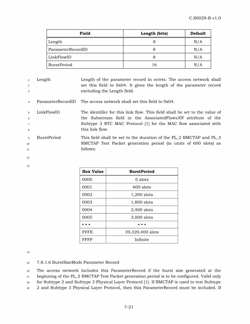
C.S0029-B v1.0
7-21
Field Length (bits) Default
Length 8 N/A
ParameterRecordID 8 N/A
LinkFlowID 8 N/A
BurstPeriod 16 N/A
Length Length of the parameter record in octets. The access network shall 1
set this field to 0x04. It gives the length of the parameter record 2
excluding the Length field. 3
ParameterRecordID The access network shall set this field to 0x04. 4
LinkFlowID The identifier for this link flow. This field shall be set to the value of 5
the Substream field in the AssociatedFlowsNN attribute of the 6
Subtype 3 RTC MAC Protocol [1] for the MAC flow associated with 7
this link flow. 8
BurstPeriod This field shall be set to the duration of the PL_2 RMCTAP and PL_3 9
RMCTAP Test Packet generation period (in units of 600 slots) as 10
follows: 11
12
13
Hex Value BurstPeriod
0000 0 slots
0001 600 slots
0002 1,200 slots
0003 1,800 slots
0004 2,400 slots
0005 3,000 slots
FFFE 39,320,400 slots
FFFF Infinite
14
7.8.1.6 BurstSizeMode Parameter Record 15
The access network includes this ParameterRecord if the burst size generated at the 16
beginning of the PL_2 RMCTAP Test Packet generation period is to be configured. Valid only 17
for Subtype 2 and Subtype 3 Physical Layer Protocol [1]. If RMCTAP is used to test Subtype 18
2 and Subtype 3 Physical Layer Protocol, then this ParameterRecord must be included. If 19

C.S0029-B v1.0
7-22
this ParameterRecord is included, then the BurstPeriodMode ParameterRecord must also 1
be included. 2
3
Field Length (bits) Default
Length 8 N/A
ParameterRecordID 8 N/A
LinkFlowID 8 N/A
BurstSize 16 N/A
Length Length of the parameter record in octets. The access network shall 4
set this field to 0x04. It gives the length of the parameter record 5
excluding the Length field. 6
ParameterRecordID The access network shall set this field to 0x05. 7
LinkFlowID The identifier for this link flow. This field shall be set to the value of 8
the Substream field in the AssociatedFlowsNN attribute of the 9
Subtype 3 RTC MAC Protocol [1] for the MAC flow associated with 10
this link flow. 11
BurstSize This field shall be set to the burst size generated at the beginning of 12
the PL_2 RMCTAP and PL_3 RMCTAP Test Packet generation period 13
(in units of 1,000 octets) as follows: 14
Hex Value BurstSize
0000 0 octets
0001 1,000 octets
0002 2,000 octets
0003 3,000 octets
0004 4,000 octets
0005 5,000 octets
FFFE 65,534,000 octets
FFFF Full buffer
15
7.8.1.7 PacketPayloadSizeModeMC Parameter Record 16
The access network includes this ParameterRecord if the Reverse Traffic Channel payload 17
size is to be configured. Valid only for Subtype 3 Physical Layer Protocol [1]. The 18
RLChannelIndex, MinPayloadSizeIndex and MaxPayloadSizeIndex fields of the Parameter 19

C.S0029-B v1.0
7-23
Record shall be repeated for all the active reverse channels assigned in 1
TrafficChannelAssignment Message. 2
3
4
Field Length (bits) Default
Length 8 N/A
ParameterRecordID 8 N/A
TCAMsgSeq 8 N/A
RLChannelCount 8 N/A
RLChannelCount occurrences of the following fields:
RLChannelIndex 8 N/A
MinPayloadSizeIndex 8 0x00
MaxPayloadSizeIndex 8 0x0C
Length Length of the parameter record in octets. The access network shall 5
set this field to three (counting ParameterRecordID, 6
MessageSequence and RLChannelCount) plus the total number of 7
RLChannelIndex, MinPayloadSizeIndex and MaxPayloadSizeIndex 8
fields for all the reverse channels assigned in the 9
TrafficChannelAssignment Message. It gives the length of the 10
parameter record excluding the Length field. 11
ParameterRecordID The access network shall set this field to 0x06. 12
TCAMsgSeq This field is included from the MessageSequence field of the last 13
TrafficChannelAssignment Message that assigned the reverse 14
channel for which this record applies. 15
RLChannelCount The access network will set thie field to the total number of reverese 16
channels assigned in the TrafficChannelAssignment Message. 17
RLChannelIndex The access network shall include this field to indicate the reverse 18
channel to which the MinPayloadSizeIndex and 19
MaxPayloadSizeIndex fields will apply. A value of ‘n’ for this field 20
defines the nth reverse link CDMA channel in the ascending order 21
of frequency that is assigned in the TrafficChannelAssignment 22
Message. 23
MinPayloadSizeIndex This field shall be set to the RTC_PL_3PayloadSizeIndex (Table 24
7.8.1.3-1) the access terminal can use to transmit the Subtype 3 25
Physical Layer Protocol RTC MAC Packets. 26
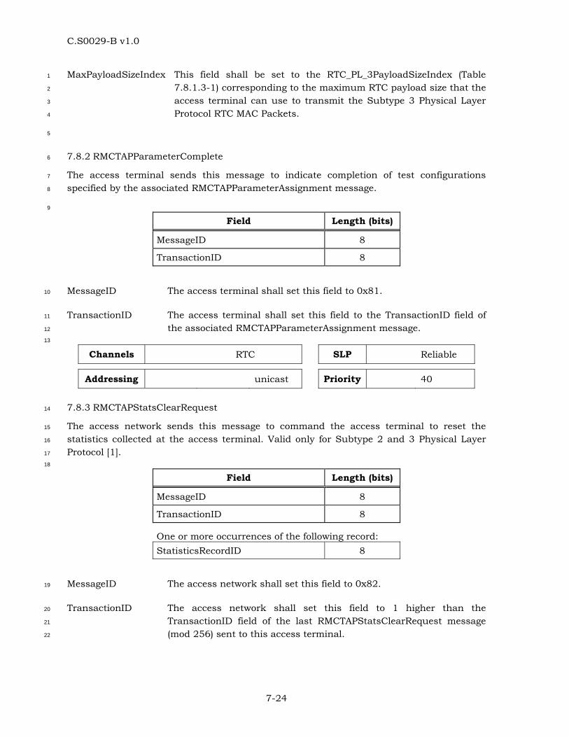
C.S0029-B v1.0
7-24
MaxPayloadSizeIndex This field shall be set to the RTC_PL_3PayloadSizeIndex (Table 1
7.8.1.3-1) corresponding to the maximum RTC payload size that the 2
access terminal can use to transmit the Subtype 3 Physical Layer 3
Protocol RTC MAC Packets. 4
5
7.8.2 RMCTAPParameterComplete 6
The access terminal sends this message to indicate completion of test configurations 7
specified by the associated RMCTAPParameterAssignment message. 8
9
Field Length (bits)
MessageID 8
TransactionID 8
MessageID The access terminal shall set this field to 0x81. 10
TransactionID The access terminal shall set this field to the TransactionID field of 11
the associated RMCTAPParameterAssignment message. 12
13
Channels RTC SLP Reliable
Addressing unicast Priority 40
7.8.3 RMCTAPStatsClearRequest 14
The access network sends this message to command the access terminal to reset the 15
statistics collected at the access terminal. Valid only for Subtype 2 and 3 Physical Layer 16
Protocol [1]. 17
18
Field Length (bits)
MessageID 8
TransactionID 8
One or more occurrences of the following record: StatisticsRecordID 8
MessageID The access network shall set this field to 0x82. 19
TransactionID The access network shall set this field to 1 higher than the 20
TransactionID field of the last RMCTAPStatsClearRequest message 21
(mod 256) sent to this access terminal. 22
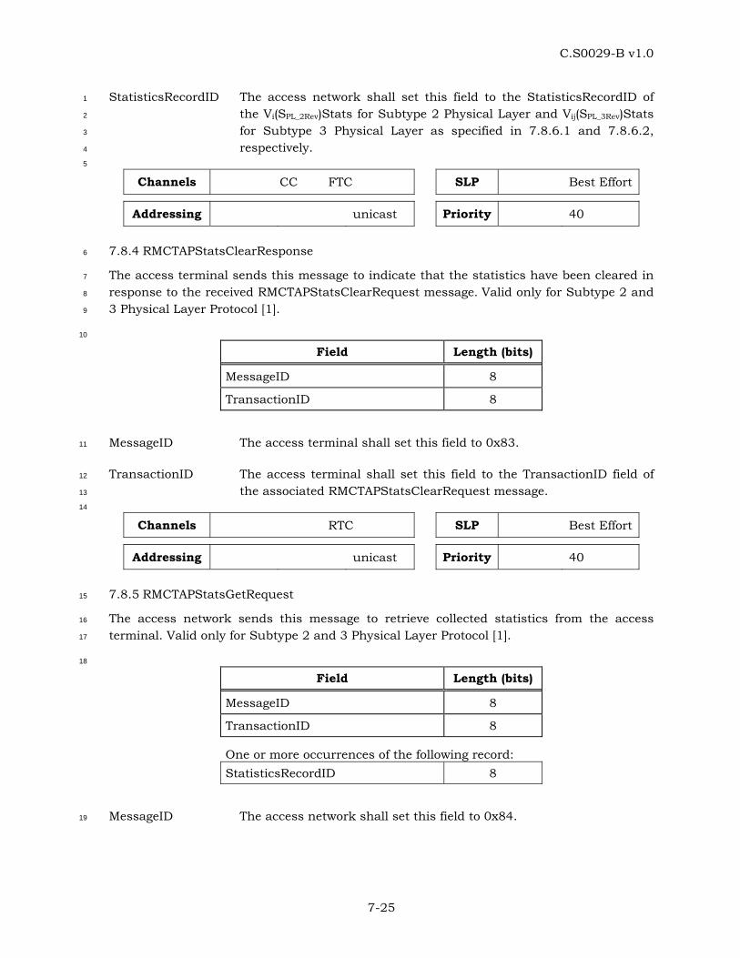
C.S0029-B v1.0
7-25
StatisticsRecordID The access network shall set this field to the StatisticsRecordID of 1
the Vi(SPL_2Rev)Stats for Subtype 2 Physical Layer and Vij(SPL_3Rev)Stats 2
for Subtype 3 Physical Layer as specified in 7.8.6.1 and 7.8.6.2, 3
respectively. 4
5
Channels CC FTC SLP Best Effort
Addressing unicast Priority 40
7.8.4 RMCTAPStatsClearResponse 6
The access terminal sends this message to indicate that the statistics have been cleared in 7
response to the received RMCTAPStatsClearRequest message. Valid only for Subtype 2 and 8
3 Physical Layer Protocol [1]. 9
10
Field Length (bits)
MessageID 8
TransactionID 8
MessageID The access terminal shall set this field to 0x83. 11
TransactionID The access terminal shall set this field to the TransactionID field of 12
the associated RMCTAPStatsClearRequest message. 13
14
Channels RTC SLP Best Effort
Addressing unicast Priority 40
7.8.5 RMCTAPStatsGetRequest 15
The access network sends this message to retrieve collected statistics from the access 16
terminal. Valid only for Subtype 2 and 3 Physical Layer Protocol [1]. 17
18
Field Length (bits)
MessageID 8
TransactionID 8
One or more occurrences of the following record: StatisticsRecordID 8
MessageID The access network shall set this field to 0x84. 19
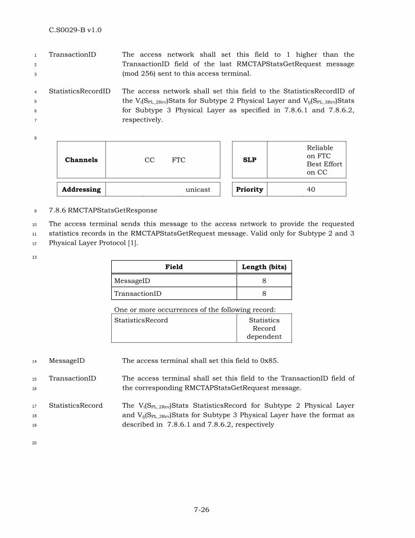
C.S0029-B v1.0
7-26
TransactionID The access network shall set this field to 1 higher than the 1
TransactionID field of the last RMCTAPStatsGetRequest message 2
(mod 256) sent to this access terminal. 3
StatisticsRecordID The access network shall set this field to the StatisticsRecordID of 4
the Vi(SPL_2Rev)Stats for Subtype 2 Physical Layer and Vij(SPL_3Rev)Stats 5
for Subtype 3 Physical Layer as specified in 7.8.6.1 and 7.8.6.2, 6
respectively. 7
8
Channels CC FTC SLP
Reliable on FTC Best Effort on CC
Addressing unicast Priority 40
7.8.6 RMCTAPStatsGetResponse 9
The access terminal sends this message to the access network to provide the requested 10
statistics records in the RMCTAPStatsGetRequest message. Valid only for Subtype 2 and 3 11
Physical Layer Protocol [1]. 12
13
Field Length (bits)
MessageID 8
TransactionID 8
One or more occurrences of the following record: StatisticsRecord Statistics
Record dependent
MessageID The access terminal shall set this field to 0x85. 14
TransactionID The access terminal shall set this field to the TransactionID field of 15
the corresponding RMCTAPStatsGetRequest message. 16
StatisticsRecord The Vi(SPL_2Rev)Stats StatisticsRecord for Subtype 2 Physical Layer 17
and Vij(SPL_3Rev)Stats for Subtype 3 Physical Layer have the format as 18
described in 7.8.6.1 and 7.8.6.2, respectively 19
20
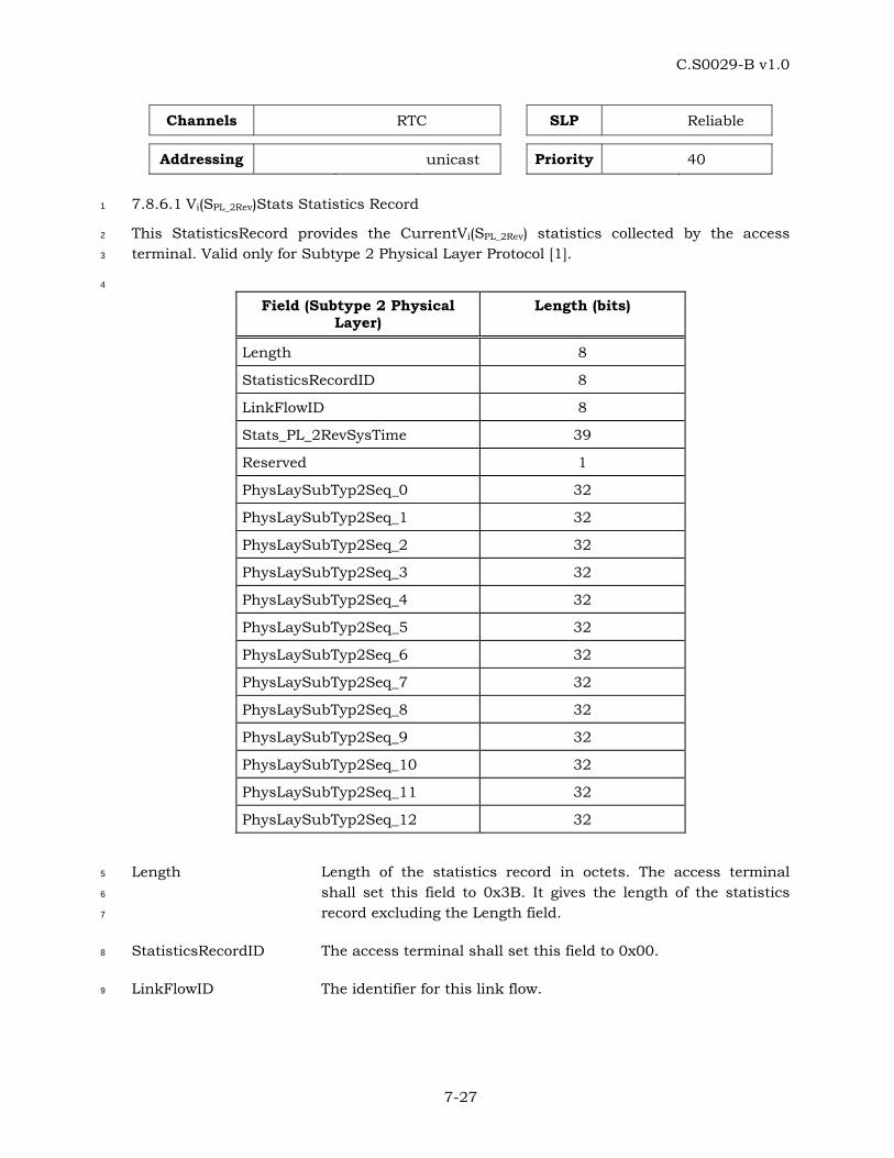
C.S0029-B v1.0
7-27
Channels RTC SLP Reliable
Addressing unicast Priority 40
7.8.6.1 Vi(SPL_2Rev)Stats Statistics Record 1
This StatisticsRecord provides the CurrentVi(SPL_2Rev) statistics collected by the access 2
terminal. Valid only for Subtype 2 Physical Layer Protocol [1]. 3
4
Field (Subtype 2 Physical Layer)
Length (bits)
Length 8
StatisticsRecordID 8
LinkFlowID 8
Stats_PL_2RevSysTime 39
Reserved 1
PhysLaySubTyp2Seq_0 32
PhysLaySubTyp2Seq_1 32
PhysLaySubTyp2Seq_2 32
PhysLaySubTyp2Seq_3 32
PhysLaySubTyp2Seq_4 32
PhysLaySubTyp2Seq_5 32
PhysLaySubTyp2Seq_6 32
PhysLaySubTyp2Seq_7 32
PhysLaySubTyp2Seq_8 32
PhysLaySubTyp2Seq_9 32
PhysLaySubTyp2Seq_10 32
PhysLaySubTyp2Seq_11 32
PhysLaySubTyp2Seq_12 32
Length Length of the statistics record in octets. The access terminal 5
shall set this field to 0x3B. It gives the length of the statistics 6
record excluding the Length field. 7
StatisticsRecordID The access terminal shall set this field to 0x00. 8
LinkFlowID The identifier for this link flow. 9
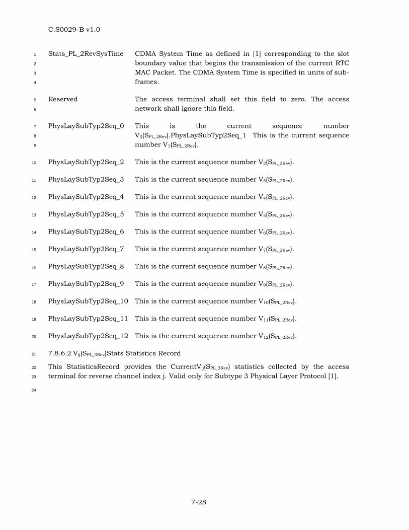
C.S0029-B v1.0
7-28
Stats_PL_2RevSysTime CDMA System Time as defined in [1] corresponding to the slot 1
boundary value that begins the transmission of the current RTC 2
MAC Packet. The CDMA System Time is specified in units of sub-3
frames. 4
Reserved The access terminal shall set this field to zero. The access 5
network shall ignore this field. 6
PhysLaySubTyp2Seq_0 This is the current sequence number 7
V0(SPL_2Rev).PhysLaySubTyp2Seq_1 This is the current sequence 8
number V1(SPL_2Rev). 9
PhysLaySubTyp2Seq_2 This is the current sequence number V2(SPL_2Rev). 10
PhysLaySubTyp2Seq_3 This is the current sequence number V3(SPL_2Rev). 11
PhysLaySubTyp2Seq_4 This is the current sequence number V4(SPL_2Rev). 12
PhysLaySubTyp2Seq_5 This is the current sequence number V5(SPL_2Rev). 13
PhysLaySubTyp2Seq_6 This is the current sequence number V6(SPL_2Rev). 14
PhysLaySubTyp2Seq_7 This is the current sequence number V7(SPL_2Rev). 15
PhysLaySubTyp2Seq_8 This is the current sequence number V8(SPL_2Rev). 16
PhysLaySubTyp2Seq_9 This is the current sequence number V9(SPL_2Rev). 17
PhysLaySubTyp2Seq_10 This is the current sequence number V10(SPL_2Rev). 18
PhysLaySubTyp2Seq_11 This is the current sequence number V11(SPL_2Rev). 19
PhysLaySubTyp2Seq_12 This is the current sequence number V12(SPL_2Rev). 20
7.8.6.2 Vij(SPL_3Rev)Stats Statistics Record 21
This StatisticsRecord provides the CurrentVij(SPL_3Rev) statistics collected by the access 22
terminal for reverse channel index j. Valid only for Subtype 3 Physical Layer Protocol [1]. 23
24
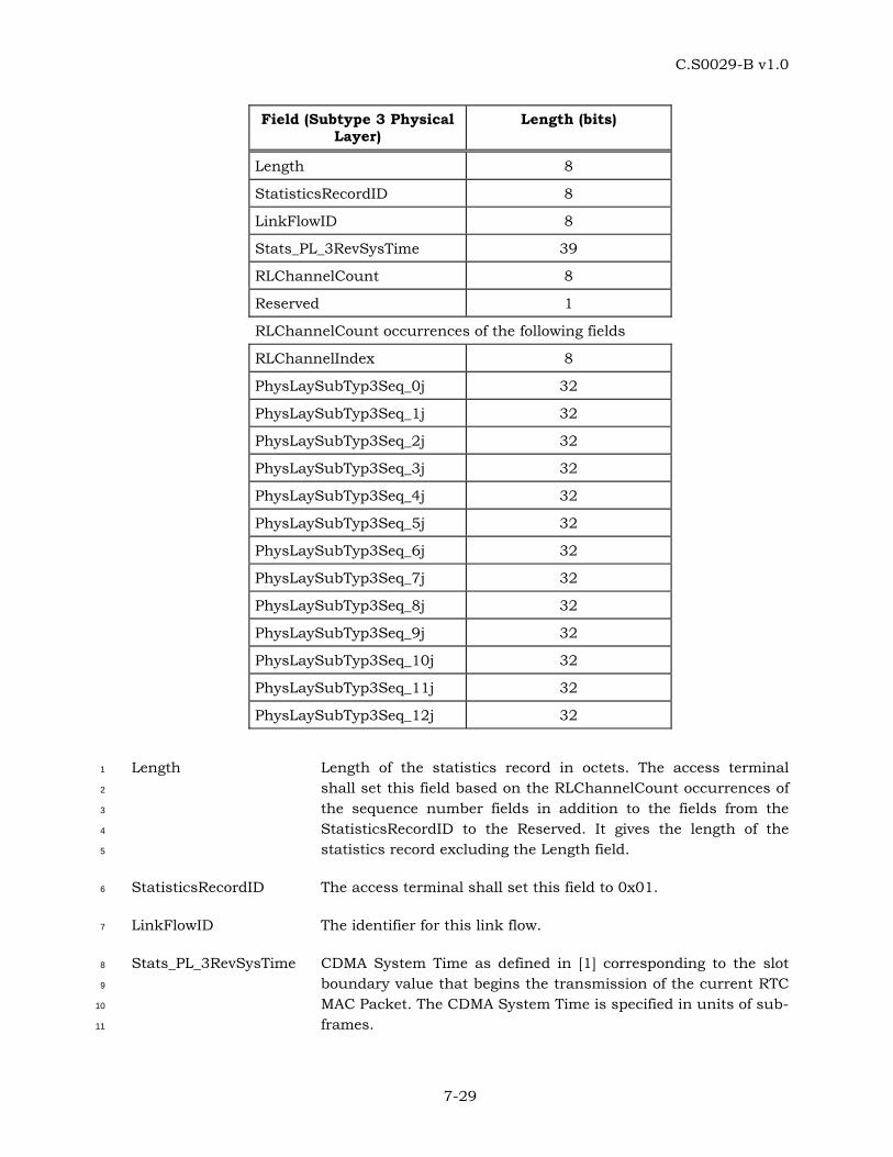
C.S0029-B v1.0
7-29
Field (Subtype 3 Physical Layer)
Length (bits)
Length 8
StatisticsRecordID 8
LinkFlowID 8
Stats_PL_3RevSysTime 39
RLChannelCount 8
Reserved 1
RLChannelCount occurrences of the following fields
RLChannelIndex 8
PhysLaySubTyp3Seq_0j 32
PhysLaySubTyp3Seq_1j 32
PhysLaySubTyp3Seq_2j 32
PhysLaySubTyp3Seq_3j 32
PhysLaySubTyp3Seq_4j 32
PhysLaySubTyp3Seq_5j 32
PhysLaySubTyp3Seq_6j 32
PhysLaySubTyp3Seq_7j 32
PhysLaySubTyp3Seq_8j 32
PhysLaySubTyp3Seq_9j 32
PhysLaySubTyp3Seq_10j 32
PhysLaySubTyp3Seq_11j 32
PhysLaySubTyp3Seq_12j 32
Length Length of the statistics record in octets. The access terminal 1
shall set this field based on the RLChannelCount occurrences of 2
the sequence number fields in addition to the fields from the 3
StatisticsRecordID to the Reserved. It gives the length of the 4
statistics record excluding the Length field. 5
StatisticsRecordID The access terminal shall set this field to 0x01. 6
LinkFlowID The identifier for this link flow. 7
Stats_PL_3RevSysTime CDMA System Time as defined in [1] corresponding to the slot 8
boundary value that begins the transmission of the current RTC 9
MAC Packet. The CDMA System Time is specified in units of sub-10
frames. 11
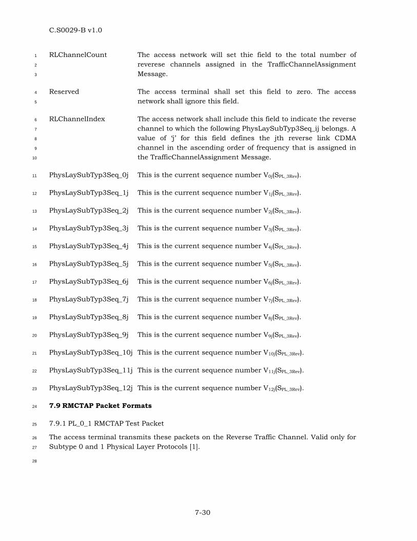
C.S0029-B v1.0
7-30
RLChannelCount The access network will set thie field to the total number of 1
reverese channels assigned in the TrafficChannelAssignment 2
Message. 3
Reserved The access terminal shall set this field to zero. The access 4
network shall ignore this field. 5
RLChannelIndex The access network shall include this field to indicate the reverse 6
channel to which the following PhysLaySubTyp3Seq_ij belongs. A 7
value of ‘j’ for this field defines the jth reverse link CDMA 8
channel in the ascending order of frequency that is assigned in 9
the TrafficChannelAssignment Message. 10
PhysLaySubTyp3Seq_0j This is the current sequence number V0j(SPL_3Rev). 11
PhysLaySubTyp3Seq_1j This is the current sequence number V1j(SPL_3Rev). 12
PhysLaySubTyp3Seq_2j This is the current sequence number V2j(SPL_3Rev). 13
PhysLaySubTyp3Seq_3j This is the current sequence number V3j(SPL_3Rev). 14
PhysLaySubTyp3Seq_4j This is the current sequence number V4j(SPL_3Rev). 15
PhysLaySubTyp3Seq_5j This is the current sequence number V5j(SPL_3Rev). 16
PhysLaySubTyp3Seq_6j This is the current sequence number V6j(SPL_3Rev). 17
PhysLaySubTyp3Seq_7j This is the current sequence number V7j(SPL_3Rev). 18
PhysLaySubTyp3Seq_8j This is the current sequence number V8j(SPL_3Rev). 19
PhysLaySubTyp3Seq_9j This is the current sequence number V9j(SPL_3Rev). 20
PhysLaySubTyp3Seq_10j This is the current sequence number V10j(SPL_3Rev). 21
PhysLaySubTyp3Seq_11j This is the current sequence number V11j(SPL_3Rev). 22
PhysLaySubTyp3Seq_12j This is the current sequence number V12j(SPL_3Rev). 23
7.9 RMCTAP Packet Formats 24
7.9.1 PL_0_1 RMCTAP Test Packet 25
The access terminal transmits these packets on the Reverse Traffic Channel. Valid only for 26
Subtype 0 and 1 Physical Layer Protocols [1]. 27
28
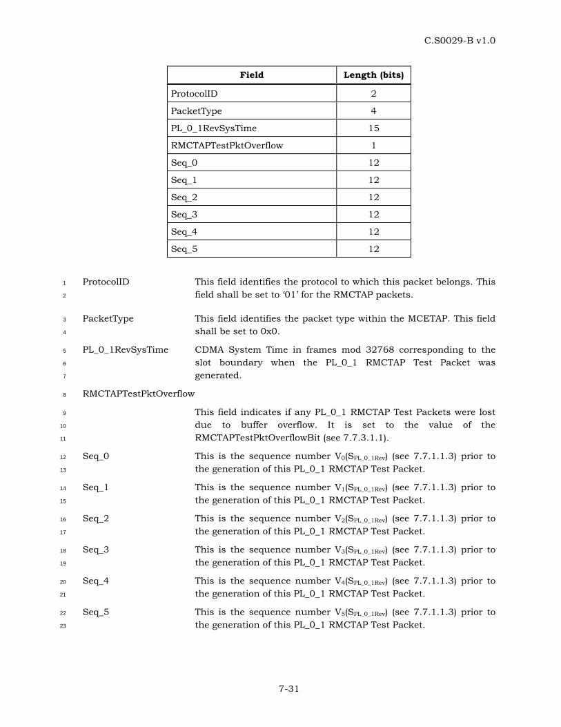
C.S0029-B v1.0
7-31
Field Length (bits)
ProtocolID 2
PacketType 4
PL_0_1RevSysTime 15
RMCTAPTestPktOverflow 1
Seq_0 12
Seq_1 12
Seq_2 12
Seq_3 12
Seq_4 12
Seq_5 12
ProtocolID This field identifies the protocol to which this packet belongs. This 1
field shall be set to ‘01’ for the RMCTAP packets. 2
PacketType This field identifies the packet type within the MCETAP. This field 3
shall be set to 0x0. 4
PL_0_1RevSysTime CDMA System Time in frames mod 32768 corresponding to the 5
slot boundary when the PL_0_1 RMCTAP Test Packet was 6
generated. 7
RMCTAPTestPktOverflow 8
This field indicates if any PL_0_1 RMCTAP Test Packets were lost 9
due to buffer overflow. It is set to the value of the 10
RMCTAPTestPktOverflowBit (see 7.7.3.1.1). 11
Seq_0 This is the sequence number V0(SPL_0_1Rev) (see 7.7.1.1.3) prior to 12
the generation of this PL_0_1 RMCTAP Test Packet. 13
Seq_1 This is the sequence number V1(SPL_0_1Rev) (see 7.7.1.1.3) prior to 14
the generation of this PL_0_1 RMCTAP Test Packet. 15
Seq_2 This is the sequence number V2(SPL_0_1Rev) (see 7.7.1.1.3) prior to 16
the generation of this PL_0_1 RMCTAP Test Packet. 17
Seq_3 This is the sequence number V3(SPL_0_1Rev) (see 7.7.1.1.3) prior to 18
the generation of this PL_0_1 RMCTAP Test Packet. 19
Seq_4 This is the sequence number V4(SPL_0_1Rev) (see 7.7.1.1.3) prior to 20
the generation of this PL_0_1 RMCTAP Test Packet. 21
Seq_5 This is the sequence number V5(SPL_0_1Rev) (see 7.7.1.1.3) prior to 22
the generation of this PL_0_1 RMCTAP Test Packet. 23
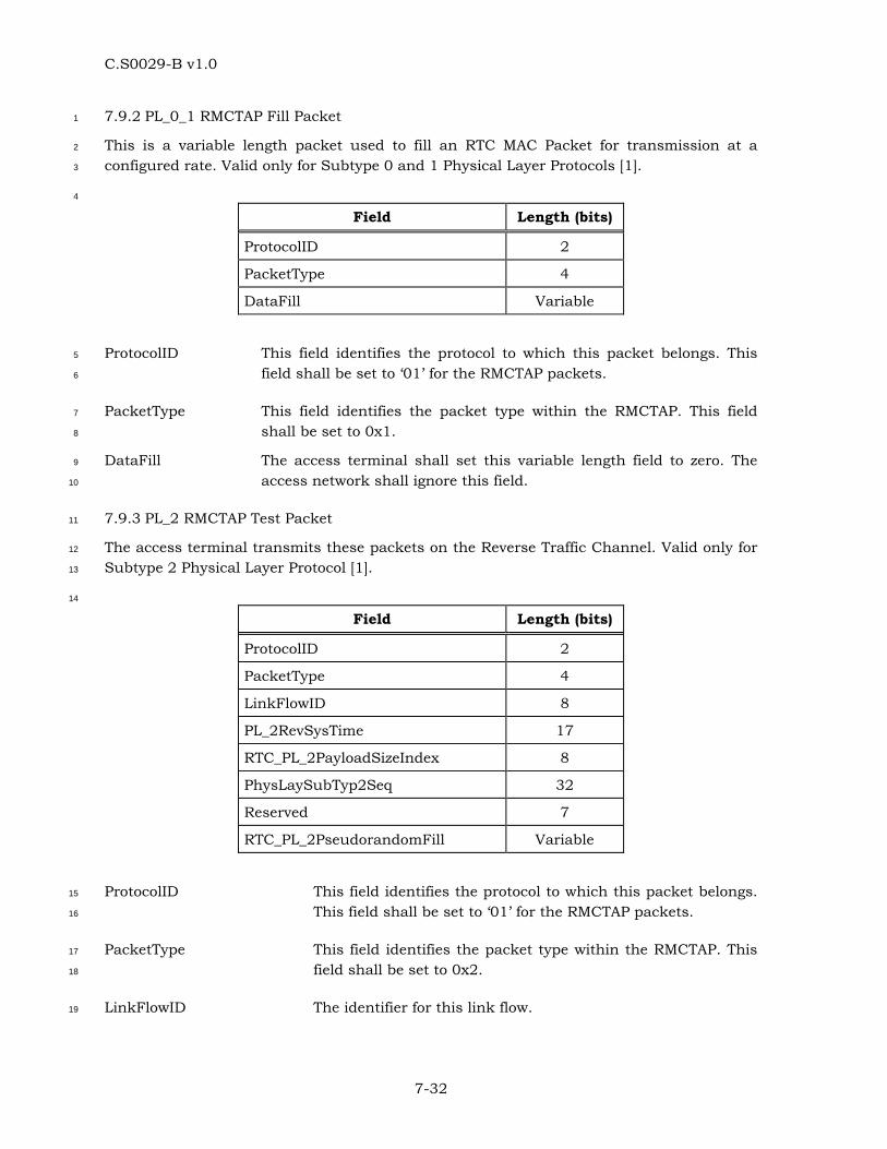
C.S0029-B v1.0
7-32
7.9.2 PL_0_1 RMCTAP Fill Packet 1
This is a variable length packet used to fill an RTC MAC Packet for transmission at a 2
configured rate. Valid only for Subtype 0 and 1 Physical Layer Protocols [1]. 3
4
Field Length (bits)
ProtocolID 2
PacketType 4
DataFill Variable
ProtocolID This field identifies the protocol to which this packet belongs. This 5
field shall be set to ‘01’ for the RMCTAP packets. 6
PacketType This field identifies the packet type within the RMCTAP. This field 7
shall be set to 0x1. 8
DataFill The access terminal shall set this variable length field to zero. The 9
access network shall ignore this field. 10
7.9.3 PL_2 RMCTAP Test Packet 11
The access terminal transmits these packets on the Reverse Traffic Channel. Valid only for 12
Subtype 2 Physical Layer Protocol [1]. 13
14
Field Length (bits)
ProtocolID 2
PacketType 4
LinkFlowID 8
PL_2RevSysTime 17
RTC_PL_2PayloadSizeIndex 8
PhysLaySubTyp2Seq 32
Reserved 7
RTC_PL_2PseudorandomFill Variable
ProtocolID This field identifies the protocol to which this packet belongs. 15
This field shall be set to ‘01’ for the RMCTAP packets. 16
PacketType This field identifies the packet type within the RMCTAP. This 17
field shall be set to 0x2. 18
LinkFlowID The identifier for this link flow. 19
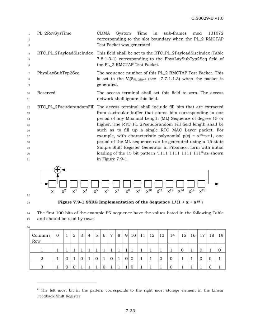
C.S0029-B v1.0
7-33
PL_2RevSysTime CDMA System Time in sub-frames mod 131072 1
corresponding to the slot boundary when the PL_2 RMCTAP 2
Test Packet was generated. 3
RTC_PL_2PayloadSizeIndex This field shall be set to the RTC_PL_2PayloadSizeIndex (Table 4
7.8.1.3-1) corresponding to the PhysLaySubTyp2Seq field of 5
the PL_2 RMCTAP Test Packet. 6
PhysLaySubTyp2Seq The sequence number of this PL_2 RMCTAP Test Packet. This 7
is set to the Vi(SPL_2Rev) (see 7.7.1.1.3) when the packet is 8
generated. 9
Reserved The access terminal shall set this field to zero. The access 10
network shall ignore this field. 11
RTC_PL_2PseudorandomFill The access terminal shall include fill bits that are extracted 12
from a circular buffer that stores bits corresponding to one 13
period of any Maximal Length (ML) Sequence of degree 15 or 14
higher. The RTC_PL_2Pseudorandom Fill field length shall be 15
such as to fill up a single RTC MAC Layer packet. For 16
example, with characteristic polynomial p(x) = x15+x+1, one 17
period of the ML sequence can be generated using a 15-state 18
Simple Shift Register Generator in Fibonacci form with initial 19
loading of the 15 bit pattern ‘1111 1111 1111 111’6as shown 20
in Figure 7.9-1. 21
+
x x2 x3 x4 x5 x6 x7 x8 x9 x10 x11 x12 x13 x14 x15 22
Figure 7.9-1 SSRG Implementation of the Sequence 1/(1 + x + x15 ) 23
The first 100 bits of the example PN sequence have the values listed in the following Table 24
and should be read by rows. 25
26
Column\ Row
0 1 2 3 4 5 6 7 8 9 10 11 12 13 14 15 16 17 18 19
1 1 1 1 1 1 1 1 1 1 1 1 1 1 1 1 0 1 0 1 0
2 1 0 1 0 1 0 1 0 1 0 0 1 1 0 0 1 1 0 0 1
3 1 0 0 1 1 1 0 1 1 1 0 1 1 1 0 1 1 1 0 1
6 The left most bit in the pattern corresponds to the right most storage element in the Linear Feedback Shift Register
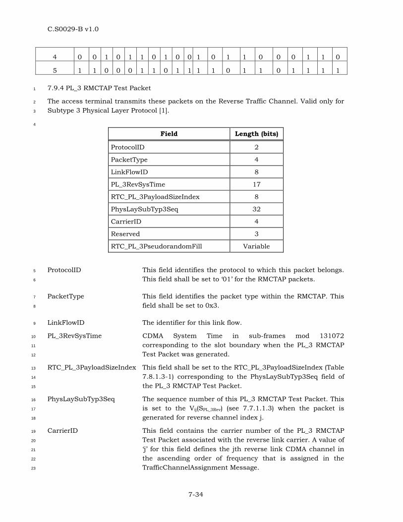
C.S0029-B v1.0
7-34
4 0 0 1 0 1 1 0 1 0 0 1 0 1 1 0 0 0 1 1 0
5 1 1 0 0 0 1 1 0 1 1 1 1 0 1 1 0 1 1 1 1
7.9.4 PL_3 RMCTAP Test Packet 1
The access terminal transmits these packets on the Reverse Traffic Channel. Valid only for 2
Subtype 3 Physical Layer Protocol [1]. 3
4
Field Length (bits)
ProtocolID 2
PacketType 4
LinkFlowID 8
PL_3RevSysTime 17
RTC_PL_3PayloadSizeIndex 8
PhysLaySubTyp3Seq 32
CarrierID 4
Reserved 3
RTC_PL_3PseudorandomFill Variable
ProtocolID This field identifies the protocol to which this packet belongs. 5
This field shall be set to ‘01’ for the RMCTAP packets. 6
PacketType This field identifies the packet type within the RMCTAP. This 7
field shall be set to 0x3. 8
LinkFlowID The identifier for this link flow. 9
PL_3RevSysTime CDMA System Time in sub-frames mod 131072 10
corresponding to the slot boundary when the PL_3 RMCTAP 11
Test Packet was generated. 12
RTC_PL_3PayloadSizeIndex This field shall be set to the RTC_PL_3PayloadSizeIndex (Table 13
7.8.1.3-1) corresponding to the PhysLaySubTyp3Seq field of 14
the PL_3 RMCTAP Test Packet. 15
PhysLaySubTyp3Seq The sequence number of this PL_3 RMCTAP Test Packet. This 16
is set to the Vij(SPL_3Rev) (see 7.7.1.1.3) when the packet is 17
generated for reverse channel index j. 18
CarrierID This field contains the carrier number of the PL_3 RMCTAP 19
Test Packet associated with the reverse link carrier. A value of 20
‘j’ for this field defines the jth reverse link CDMA channel in 21
the ascending order of frequency that is assigned in the 22
TrafficChannelAssignment Message. 23
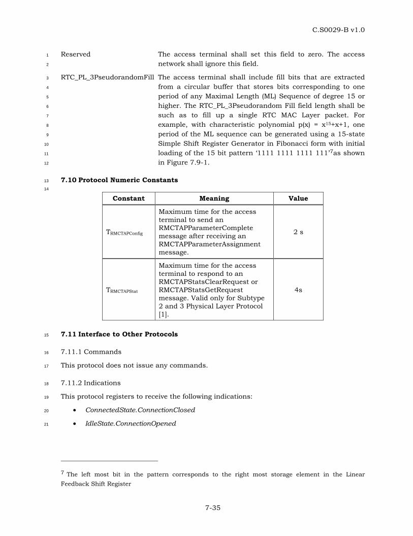
C.S0029-B v1.0
7-35
Reserved The access terminal shall set this field to zero. The access 1
network shall ignore this field. 2
RTC_PL_3PseudorandomFill The access terminal shall include fill bits that are extracted 3
from a circular buffer that stores bits corresponding to one 4
period of any Maximal Length (ML) Sequence of degree 15 or 5
higher. The RTC_PL_3Pseudorandom Fill field length shall be 6
such as to fill up a single RTC MAC Layer packet. For 7
example, with characteristic polynomial p(x) = x15+x+1, one 8
period of the ML sequence can be generated using a 15-state 9
Simple Shift Register Generator in Fibonacci form with initial 10
loading of the 15 bit pattern ‘1111 1111 1111 111’7as shown 11
in Figure 7.9-1. 12
7.10 Protocol Numeric Constants 13
14
Constant Meaning Value
TRMCTAPConfig
Maximum time for the access terminal to send an RMCTAPParameterComplete message after receiving an RMCTAPParameterAssignment message.
2 s
TRMCTAPStat
Maximum time for the access terminal to respond to an RMCTAPStatsClearRequest or RMCTAPStatsGetRequest message. Valid only for Subtype 2 and 3 Physical Layer Protocol [1].
4s
7.11 Interface to Other Protocols 15
7.11.1 Commands 16
This protocol does not issue any commands. 17
7.11.2 Indications 18
This protocol registers to receive the following indications: 19
• ConnectedState.ConnectionClosed 20
• IdleState.ConnectionOpened 21
7 The left most bit in the pattern corresponds to the right most storage element in the Linear Feedback Shift Register

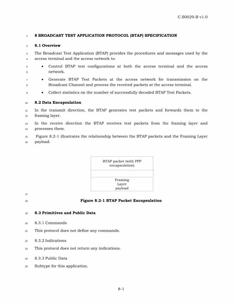
C.S0029-B v1.0
8-1
8 BROADCAST TEST APPLICATION PROTOCOL (BTAP) SPECIFICATION 1
8.1 Overview 2
The Broadcast Test Application (BTAP) provides the procedures and messages used by the 3
access terminal and the access network to: 4
• Control BTAP test configurations at both the access terminal and the access 5
network. 6
• Generate BTAP Test Packets at the access network for transmission on the 7
Broadcast Channel and process the received packets at the access terminal. 8
• Collect statistics on the number of successfully decoded BTAP Test Packets. 9
8.2 Data Encapsulation 10
In the transmit direction, the BTAP generates test packets and forwards them to the 11
framing layer. 12
In the receive direction the BTAP receives test packets from the framing layer and 13
processes them. 14
Figure 8.2-1 illustrates the relationship between the BTAP packets and the Framing Layer 15
payload. 16
FramingLayer
payload
BTAP packet (with PPPencapsulation)
17
Figure 8.2-1 BTAP Packet Encapsulation 18
8.3 Primitives and Public Data 19
8.3.1 Commands 20
This protocol does not define any commands. 21
8.3.2 Indications 22
This protocol does not return any indications. 23
8.3.3 Public Data 24
Subtype for this application. 25
C.S0029-B v1.0
8-2
8.4 Basic Protocol Numbers 1
BTAP shall use the application subtype value for the Broadcast Test Application specified 2
in 1.5. 3
8.5 Protocol Data Unit 4
The transmission unit of this protocol is a BTAP packet. The BTAP packet size is 5
determined by the lower layers as specified in [5]. 6
The BTAP also uses signaling messages for controlling and configuring the access terminal 7
and the access network for conducting tests on the Broadcast Channel. When BTAP sends 8
these messages it shall use the Signaling Application [1]. 9
8.6 Test Statistics 10
8.6.1 Access Terminal Requirements 11
The access terminal shall maintain the following statistics: 12
• StartTime: CDMA System Time in slots when the access terminal started decoding 13
Error Control Blocks on the Broadcast Channel. 14
• StopTime: CDMA System Time in slots when the access terminal stopped decoding 15
Error Control Blocks on the Broadcast Channel. 16
• BTAPTestPktRecd: This counts the number of BTAP Test Packets that were 17
successfully decoded by the access terminal on the Broadcast Channel from 18
StartTime to StopTime. 19
8.7 Procedures 20
BTAP is specified by the following procedures, which control and configure different aspects 21
of the Broadcast Channel tests. 22
• Test Parameter Configuration: Procedures and messages for configuring parameters 23
for different tests. 24
• Access Terminal Statistics Collection and Retrieval: Procedures and messages for 25
resetting the statistics being collected at the access terminal and for retrieving 26
them. 27
• BTAP Test Packet Transmission and Reception: Procedures for sending and 28
receiving BTAP Test Packets on the Broadcast Channel. 29
8.7.1 Test Parameter Configuration 30
8.7.1.1 Access Terminal Requirements 31
When the protocol is instantiated, the access terminal shall execute the configuration 32
initialization procedure in 8.7.1.1.1 . 33
If the access terminal receives a BTAPParameterAssignment message, it shall do the 34
following steps in sequence: 35
C.S0029-B v1.0
8-3
• Execute the configuration initialization procedures in 8.7.1.1.1. 1
• If the message includes the BTAPTestPktEnable parameter record, then the BTAP 2
Test Packet mode is enabled. 3
• Send a BTAPParameterComplete message. The TransactionID field shall be set to 4
the same value as that received in the BTAPParameterAssignment message. The 5
BTAPParameterComplete message shall be sent within TBTAPConfig from when the 6
BTAPParameterAssignment message is received. 7
8.7.1.1.1 Access Terminal Configuration Initialization 8
When the protocol is instantiated, the access terminal shall initialize the test configuration 9
as follows: 10
• The BTAPTestPktEnable mode is disabled. 11
8.7.1.2 Access Network Requirements 12
In the BroadcastOverhead message [5], if the BCMCSFlowIDLength field is set to ‘1’, ‘2’, or 13
‘3’, then the access network shall set the BCMCSFlowID to 0xFFFF, 0xFFFFFF, or 14
0xFFFFFFFF, respectively. 15
To change the test configuration the access network shall perform the following steps: 16
Send a BroadcastOverhead message [5] to the access terminal after modifying the 17
appropriate fields of the BroadcastOverhead message in order to change the test 18
configuration. 19
8.7.2 Access Terminal Statistics Collection and Retrieval 20
8.7.2.1 Access Terminal Requirements 21
When the protocol is instantiated, the access terminal shall execute the Statistics 22
Initialization procedure in 8.7.2.1.1 . 23
If the access terminal receives a BTAPStatsClearRequest message the access terminal shall 24
• Execute the Statistics Initialization procedure as follows: 25
o If StatisticsRecordID is equal to 0x00, set StartTime, StopTime, and 26
BTAPTestPktRecd to zero. 27
• Send a BTAPStatsClearResponse message within TBTAPStat. 28
When the BTAP Test Packet mode is enabled 29
• BTAPTestPktRecd shall be incremented whenever a BTAP Test Packet has been 30
successfully decoded by the access terminal on the Broadcast Channel. 31
If the access terminal receives a BTAPStatsGetRequest message, it shall respond within 32
TBTAPStat with a BTAPStatsGetResponse message containing the requested statistics records. 33
8.7.2.1.1 Statistics Initialization 34
The access terminal shall set 35
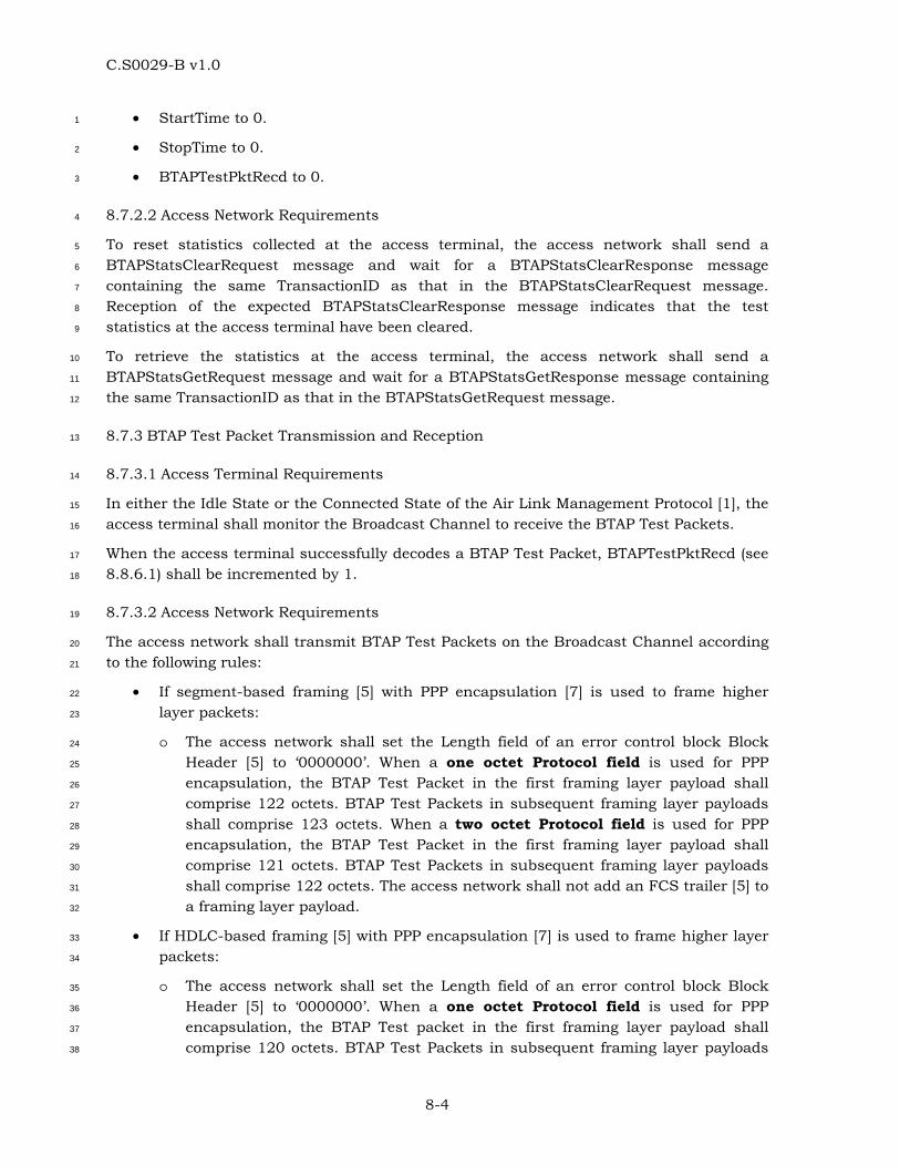
C.S0029-B v1.0
8-4
• StartTime to 0. 1
• StopTime to 0. 2
• BTAPTestPktRecd to 0. 3
8.7.2.2 Access Network Requirements 4
To reset statistics collected at the access terminal, the access network shall send a 5
BTAPStatsClearRequest message and wait for a BTAPStatsClearResponse message 6
containing the same TransactionID as that in the BTAPStatsClearRequest message. 7
Reception of the expected BTAPStatsClearResponse message indicates that the test 8
statistics at the access terminal have been cleared. 9
To retrieve the statistics at the access terminal, the access network shall send a 10
BTAPStatsGetRequest message and wait for a BTAPStatsGetResponse message containing 11
the same TransactionID as that in the BTAPStatsGetRequest message. 12
8.7.3 BTAP Test Packet Transmission and Reception 13
8.7.3.1 Access Terminal Requirements 14
In either the Idle State or the Connected State of the Air Link Management Protocol [1], the 15
access terminal shall monitor the Broadcast Channel to receive the BTAP Test Packets. 16
When the access terminal successfully decodes a BTAP Test Packet, BTAPTestPktRecd (see 17
8.8.6.1) shall be incremented by 1. 18
8.7.3.2 Access Network Requirements 19
The access network shall transmit BTAP Test Packets on the Broadcast Channel according 20
to the following rules: 21
• If segment-based framing [5] with PPP encapsulation [7] is used to frame higher 22
layer packets: 23
o The access network shall set the Length field of an error control block Block 24
Header [5] to ‘0000000’. When a one octet Protocol field is used for PPP 25
encapsulation, the BTAP Test Packet in the first framing layer payload shall 26
comprise 122 octets. BTAP Test Packets in subsequent framing layer payloads 27
shall comprise 123 octets. When a two octet Protocol field is used for PPP 28
encapsulation, the BTAP Test Packet in the first framing layer payload shall 29
comprise 121 octets. BTAP Test Packets in subsequent framing layer payloads 30
shall comprise 122 octets. The access network shall not add an FCS trailer [5] to 31
a framing layer payload. 32
• If HDLC-based framing [5] with PPP encapsulation [7] is used to frame higher layer 33
packets: 34
o The access network shall set the Length field of an error control block Block 35
Header [5] to ‘0000000’. When a one octet Protocol field is used for PPP 36
encapsulation, the BTAP Test packet in the first framing layer payload shall 37
comprise 120 octets. BTAP Test Packets in subsequent framing layer payloads 38
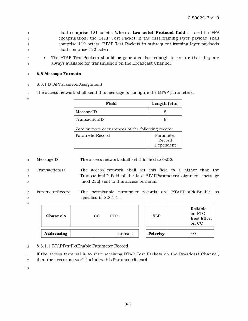
C.S0029-B v1.0
8-5
shall comprise 121 octets. When a two octet Protocol field is used for PPP 1
encapsulation, the BTAP Test Packet in the first framing layer payload shall 2
comprise 119 octets. BTAP Test Packets in subsequent framing layer payloads 3
shall comprise 120 octets. 4
• The BTAP Test Packets should be generated fast enough to ensure that they are 5
always available for transmission on the Broadcast Channel. 6
8.8 Message Formats 7
8.8.1 BTAPParameterAssignment 8
The access network shall send this message to configure the BTAP parameters. 9
10
Field Length (bits)
MessageID 8
TransactionID 8
Zero or more occurrences of the following record: ParameterRecord Parameter
Record Dependent
MessageID The access network shall set this field to 0x00. 11
TransactionID The access network shall set this field to 1 higher than the 12
TransactionID field of the last BTAPParameterAssignment message 13
(mod 256) sent to this access terminal. 14
ParameterRecord The permissible parameter records are BTAPTestPktEnable as 15
specified in 8.8.1.1 . 16
17
Channels CC FTC SLP
Reliable on FTC Best Effort on CC
Addressing unicast Priority 40
8.8.1.1 BTAPTestPktEnable Parameter Record 18
If the access terminal is to start receiving BTAP Test Packets on the Broadcast Channel, 19
then the access network includes this ParameterRecord. 20
21
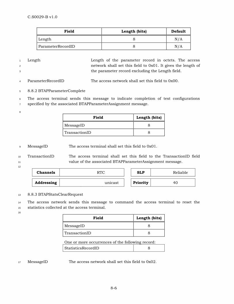
C.S0029-B v1.0
8-6
Field Length (bits) Default
Length 8 N/A
ParameterRecordID 8 N/A
Length Length of the parameter record in octets. The access 1
network shall set this field to 0x01. It gives the length of 2
the parameter record excluding the Length field. 3
ParameterRecordID The access network shall set this field to 0x00. 4
8.8.2 BTAPParameterComplete 5
The access terminal sends this message to indicate completion of test configurations 6
specified by the associated BTAPParameterAssignment message. 7
8
Field Length (bits)
MessageID 8
TransactionID 8
MessageID The access terminal shall set this field to 0x01. 9
TransactionID The access terminal shall set this field to the TransactionID field 10
value of the associated BTAPParameterAssignment message. 11
12
Channels RTC SLP Reliable
Addressing unicast Priority 40
8.8.3 BTAPStatsClearRequest 13
The access network sends this message to command the access terminal to reset the 14
statistics collected at the access terminal. 15
16
Field Length (bits)
MessageID 8
TransactionID 8
One or more occurrences of the following record: StatisticsRecordID 8
MessageID The access network shall set this field to 0x02. 17
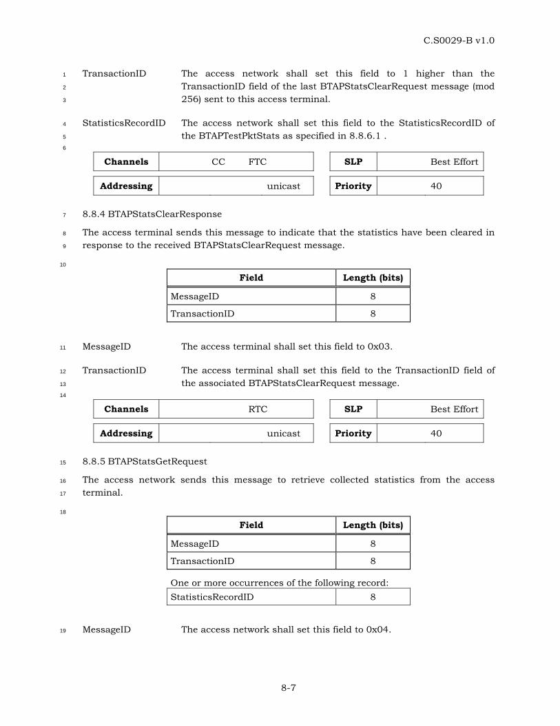
C.S0029-B v1.0
8-7
TransactionID The access network shall set this field to 1 higher than the 1
TransactionID field of the last BTAPStatsClearRequest message (mod 2
256) sent to this access terminal. 3
StatisticsRecordID The access network shall set this field to the StatisticsRecordID of 4
the BTAPTestPktStats as specified in 8.8.6.1 . 5
6
Channels CC FTC SLP Best Effort
Addressing unicast Priority 40
8.8.4 BTAPStatsClearResponse 7
The access terminal sends this message to indicate that the statistics have been cleared in 8
response to the received BTAPStatsClearRequest message. 9
10
Field Length (bits)
MessageID 8
TransactionID 8
MessageID The access terminal shall set this field to 0x03. 11
TransactionID The access terminal shall set this field to the TransactionID field of 12
the associated BTAPStatsClearRequest message. 13
14
Channels RTC SLP Best Effort
Addressing unicast Priority 40
8.8.5 BTAPStatsGetRequest 15
The access network sends this message to retrieve collected statistics from the access 16
terminal. 17
18
Field Length (bits)
MessageID 8
TransactionID 8
One or more occurrences of the following record: StatisticsRecordID 8
MessageID The access network shall set this field to 0x04. 19
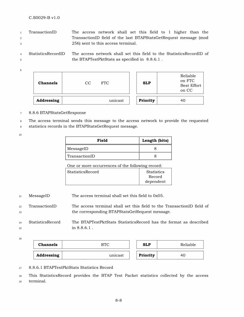
C.S0029-B v1.0
8-8
TransactionID The access network shall set this field to 1 higher than the 1
TransactionID field of the last BTAPStatsGetRequest message (mod 2
256) sent to this access terminal. 3
StatisticsRecordID The access network shall set this field to the StatisticsRecordID of 4
the BTAPTestPktStats as specified in 8.8.6.1 . 5
6
Channels CC FTC SLP
Reliable on FTC Best Effort on CC
Addressing unicast Priority 40
8.8.6 BTAPStatsGetResponse 7
The access terminal sends this message to the access network to provide the requested 8
statistics records in the BTAPStatsGetRequest message. 9
10
Field Length (bits)
MessageID 8
TransactionID 8
One or more occurrences of the following record: StatisticsRecord Statistics
Record dependent
MessageID The access terminal shall set this field to 0x05. 11
TransactionID The access terminal shall set this field to the TransactionID field of 12
the corresponding BTAPStatsGetRequest message. 13
StatisticsRecord The BTAPTestPktStats StatisticsRecord has the format as described 14
in 8.8.6.1 . 15
16
Channels RTC SLP Reliable
Addressing unicast Priority 40
8.8.6.1 BTAPTestPktStats Statistics Record 17
This StatisticsRecord provides the BTAP Test Packet statistics collected by the access 18
terminal. 19
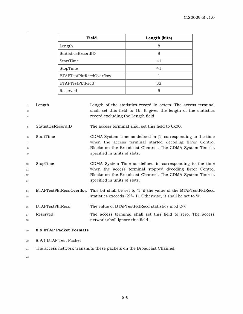
C.S0029-B v1.0
8-9
1
Field Length (bits)
Length 8
StatisticsRecordID 8
StartTime 41
StopTime 41
BTAPTestPktRecdOverflow 1
BTAPTestPktRecd 32
Reserved 5
Length Length of the statistics record in octets. The access terminal 2
shall set this field to 16. It gives the length of the statistics 3
record excluding the Length field. 4
StatisticsRecordID The access terminal shall set this field to 0x00. 5
StartTime CDMA System Time as defined in [1] corresponding to the time 6
when the access terminal started decoding Error Control 7
Blocks on the Broadcast Channel. The CDMA System Time is 8
specified in units of slots. 9
StopTime CDMA System Time as defined in corresponding to the time 10
when the access terminal stopped decoding Error Control 11
Blocks on the Broadcast Channel. The CDMA System Time is 12
specified in units of slots. 13
BTAPTestPktRecdOverflow This bit shall be set to ‘1’ if the value of the BTAPTestPktRecd 14
statistics exceeds (232- 1). Otherwise, it shall be set to ‘0’. 15
BTAPTestPktRecd The value of BTAPTestPktRecd statistics mod 232. 16
Reserved The access terminal shall set this field to zero. The access 17
network shall ignore this field. 18
8.9 BTAP Packet Formats 19
8.9.1 BTAP Test Packet 20
The access network transmits these packets on the Broadcast Channel. 21
22
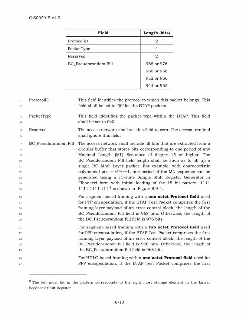
C.S0029-B v1.0
8-10
Field Length (bits)
ProtocolID 2
PacketType 4
Reserved 2
BC_Pseudorandom Fill 968 or 976
960 or 968
952 or 960
944 or 952
ProtocolID This field identifies the protocol to which this packet belongs. This 1
field shall be set to ‘00’ for the BTAP packets. 2
PacketType This field identifies the packet type within the BTAP. This field 3
shall be set to 0x0. 4
Reserved The access network shall set this field to zero. The access terminal 5
shall ignore this field. 6
BC_Pseudorandom Fill The access network shall include fill bits that are extracted from a 7
circular buffer that stores bits corresponding to one period of any 8
Maximal Length (ML) Sequence of degree 15 or higher. The 9
BC_Pseudorandom Fill field length shall be such as to fill up a 10
single BC MAC Layer packet. For example, with characteristic 11
polynomial p(x) = x15+x+1, one period of the ML sequence can be 12
generated using a 15-state Simple Shift Register Generator in 13
Fibonacci form with initial loading of the 15 bit pattern ‘1111 14
1111 1111 111’8as shown in Figure 8.9-1. 15
For segment-based framing with a one octet Protocol field used 16
for PPP encapsulation, if the BTAP Test Packet comprises the first 17
framing layer payload of an error control block, the length of the 18
BC_Pseudorandom Fill field is 968 bits. Otherwise, the length of 19
the BC_Pseudorandom Fill field is 976 bits. 20
For segment-based framing with a two octet Protocol field used 21
for PPP encapsulation, if the BTAP Test Packet comprises the first 22
framing layer payload of an error control block, the length of the 23
BC_Pseudorandom Fill field is 960 bits. Otherwise, the length of 24
the BC_Pseudorandom Fill field is 968 bits. 25
For HDLC-based framing with a one octet Protocol field used for 26
PPP encapsulation, if the BTAP Test Packet comprises the first 27
8 The left most bit in the pattern corresponds to the right most storage element in the Linear Feedback Shift Register
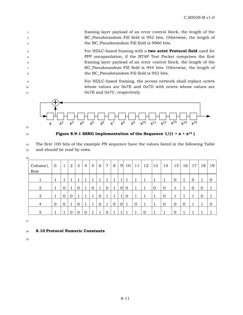
C.S0029-B v1.0
8-11
framing layer payload of an error control block, the length of the 1
BC_Pseudorandom Fill field is 952 bits. Otherwise, the length of 2
the BC_Pseudorandom Fill field is 9960 bits. 3
For HDLC-based framing with a two octet Protocol field used for 4
PPP encapsulation, if the BTAP Test Packet comprises the first 5
framing layer payload of an error control block, the length of the 6
BC_Pseudorandom Fill field is 944 bits. Otherwise, the length of 7
the BC_Pseudorandom Fill field is 952 bits. 8
For HDLC-based framing, the access network shall replace octets 9
whose values are 0x7E and 0x7D with octets whose values are 10
0x7B and 0x7C, respectively. 11
+
x x2 x3 x4 x5 x6 x7 x8 x9 x10 x11 x12 x13 x14 x15 12
Figure 8.9-1 SSRG Implementation of the Sequence 1/(1 + x + x15 ) 13
The first 100 bits of the example PN sequence have the values listed in the following Table 14
and should be read by rows. 15
16
Column\ Row
0 1 2 3 4 5 6 7 8 9 10 11 12 13 14 15 16 17 18 19
1 1 1 1 1 1 1 1 1 1 1 1 1 1 1 1 0 1 0 1 0
2 1 0 1 0 1 0 1 0 1 0 0 1 1 0 0 1 1 0 0 1
3 1 0 0 1 1 1 0 1 1 1 0 1 1 1 0 1 1 1 0 1
4 0 0 1 0 1 1 0 1 0 0 1 0 1 1 0 0 0 1 1 0
5 1 1 0 0 0 1 1 0 1 1 1 1 0 1 1 0 1 1 1 1
17
8.10 Protocol Numeric Constants 18
19
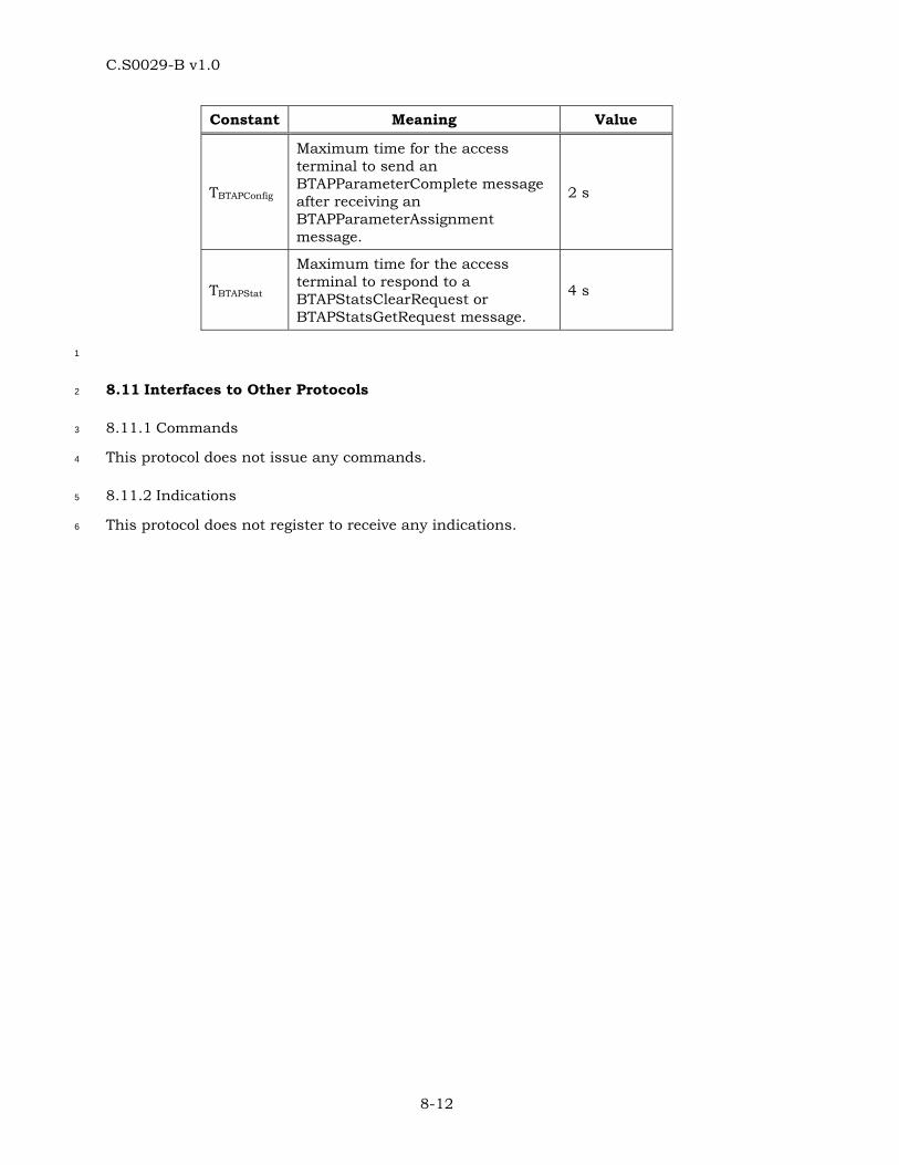
C.S0029-B v1.0
8-12
Constant Meaning Value
TBTAPConfig
Maximum time for the access terminal to send an BTAPParameterComplete message after receiving an BTAPParameterAssignment message.
2 s
TBTAPStat
Maximum time for the access terminal to respond to a BTAPStatsClearRequest or BTAPStatsGetRequest message.
4 s
1
8.11 Interfaces to Other Protocols 2
8.11.1 Commands 3
This protocol does not issue any commands. 4
8.11.2 Indications 5
This protocol does not register to receive any indications. 6
C.S0029-B v1.0
9-1
9 TEST APPLICATION EXAMPLE FLOW DIAGRAMS 1
9.1 Overview 2
This section provides some Test Application Protocol, Enhanced Test Application Protocol, 3
Multicarrier Test Application Protocol and Broadcast Test Application Protocol flow 4
diagrams to illustrate the use of FTAP/FETAP/FMCTAP, RTAP/RETAP/RMCTAP, and BTAP 5
procedures for characterizing the Forward and Reverse Traffic Channels and Broadcast 6
Channel. It also provides some sample computations of performance measures. For 7
FMCTAP and RMCTAP, the flow diagrams are shown on a per carrier basis. These are for 8
informational purpose only. The tests that can be performed using these procedures and 9
the manner, in which they can be conducted, are by no means limited to these few 10
illustrations. In the test example flow diagrams, it is assumed that the Stream associated 11
with the Test Application Protocol, Enhanced Test Application Protocol, Multicarrier Test 12
Application Protocol and Broadcast Test Application Protocol was successfully negotiated 13
earlier as part of Stream Protocol Configuration. 14
9.2 Forward Link Performance Tests 15
This section illustrates the use of FTAP, FETAP and FMCTAP procedures for three 16
scenarios, namely statistics retrieval from the access terminal, throughput and packet 17
error rate measurement on the Subtype 0 Physical Layer Protocol and throughput and 18
packet error rate for Subtype 3 Physical Layer Protocol Forward Link. 19
9.2.1 Statistics Collection and Retrieval at the Access Terminal 20
The first example illustrates a scenario for retrieving test statistics collected at the access 21
terminal for verifying access terminal compliance in meeting Control Channel Packet Error 22
Rate performance in the Idle State. FTAP signaling messages are used if application 23
subtype 0x0003 is instantiated. FETAP signaling messages are used if application subtype 24
0x000A is instantiated. FMCTAP signaling messages are used if application subtype 25
0x000E is instantiated. 26
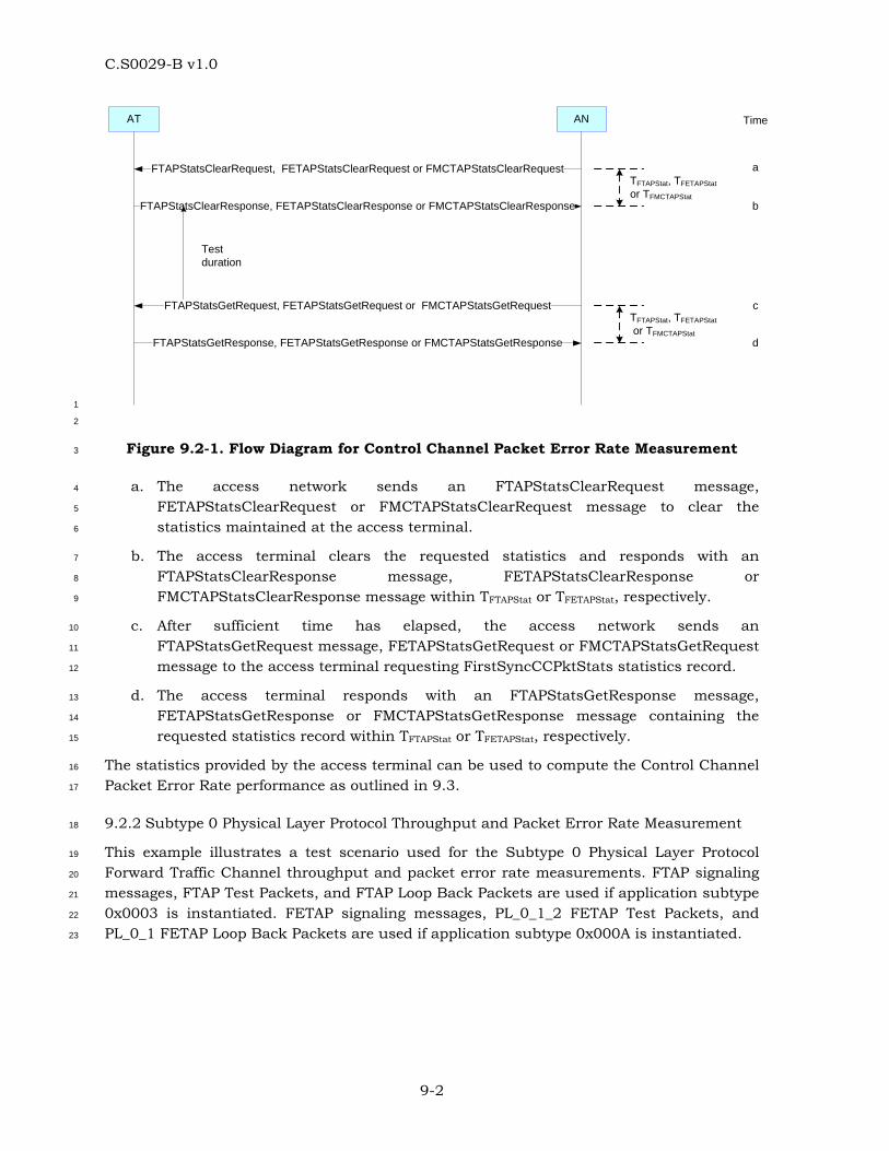
C.S0029-B v1.0
9-2
AT AN
FTAPStatsClearRequest, FETAPStatsClearRequest or FMCTAPStatsClearRequest a
b
c
d
Time
FTAPStatsClearResponse, FETAPStatsClearResponse or FMCTAPStatsClearResponse
TFTAPStat, TFETAPStator TFMCTAPStat
Test duration
FTAPStatsGetRequest, FETAPStatsGetRequest or FMCTAPStatsGetRequest
FTAPStatsGetResponse, FETAPStatsGetResponse or FMCTAPStatsGetResponse
TFTAPStat, TFETAPStat or TFMCTAPStat
1
2
Figure 9.2-1. Flow Diagram for Control Channel Packet Error Rate Measurement 3
a. The access network sends an FTAPStatsClearRequest message, 4
FETAPStatsClearRequest or FMCTAPStatsClearRequest message to clear the 5
statistics maintained at the access terminal. 6
b. The access terminal clears the requested statistics and responds with an 7
FTAPStatsClearResponse message, FETAPStatsClearResponse or 8
FMCTAPStatsClearResponse message within TFTAPStat or TFETAPStat, respectively. 9
c. After sufficient time has elapsed, the access network sends an 10
FTAPStatsGetRequest message, FETAPStatsGetRequest or FMCTAPStatsGetRequest 11
message to the access terminal requesting FirstSyncCCPktStats statistics record. 12
d. The access terminal responds with an FTAPStatsGetResponse message, 13
FETAPStatsGetResponse or FMCTAPStatsGetResponse message containing the 14
requested statistics record within TFTAPStat or TFETAPStat, respectively. 15
The statistics provided by the access terminal can be used to compute the Control Channel 16
Packet Error Rate performance as outlined in 9.3. 17
9.2.2 Subtype 0 Physical Layer Protocol Throughput and Packet Error Rate Measurement 18
This example illustrates a test scenario used for the Subtype 0 Physical Layer Protocol 19
Forward Traffic Channel throughput and packet error rate measurements. FTAP signaling 20
messages, FTAP Test Packets, and FTAP Loop Back Packets are used if application subtype 21
0x0003 is instantiated. FETAP signaling messages, PL_0_1_2 FETAP Test Packets, and 22
PL_0_1 FETAP Loop Back Packets are used if application subtype 0x000A is instantiated. 23
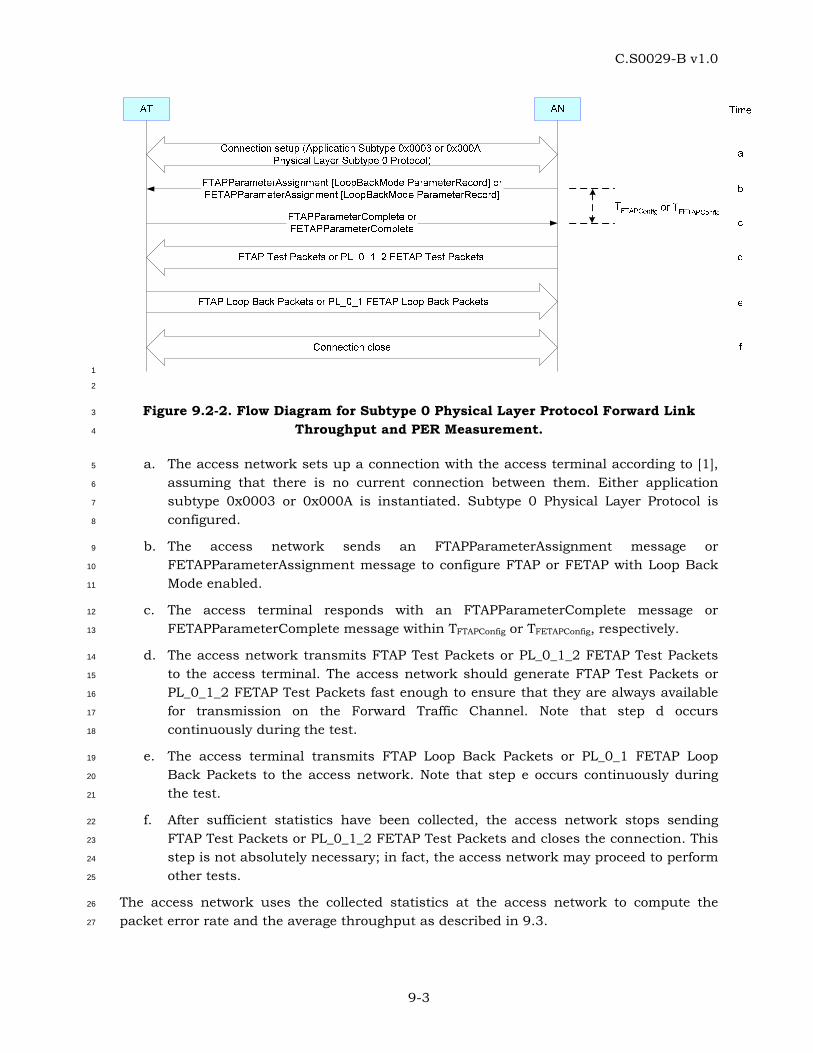
C.S0029-B v1.0
9-3
1
2
Figure 9.2-2. Flow Diagram for Subtype 0 Physical Layer Protocol Forward Link 3
Throughput and PER Measurement. 4
a. The access network sets up a connection with the access terminal according to [1], 5
assuming that there is no current connection between them. Either application 6
subtype 0x0003 or 0x000A is instantiated. Subtype 0 Physical Layer Protocol is 7
configured. 8
b. The access network sends an FTAPParameterAssignment message or 9
FETAPParameterAssignment message to configure FTAP or FETAP with Loop Back 10
Mode enabled. 11
c. The access terminal responds with an FTAPParameterComplete message or 12
FETAPParameterComplete message within TFTAPConfig or TFETAPConfig, respectively. 13
d. The access network transmits FTAP Test Packets or PL_0_1_2 FETAP Test Packets 14
to the access terminal. The access network should generate FTAP Test Packets or 15
PL_0_1_2 FETAP Test Packets fast enough to ensure that they are always available 16
for transmission on the Forward Traffic Channel. Note that step d occurs 17
continuously during the test. 18
e. The access terminal transmits FTAP Loop Back Packets or PL_0_1 FETAP Loop 19
Back Packets to the access network. Note that step e occurs continuously during 20
the test. 21
f. After sufficient statistics have been collected, the access network stops sending 22
FTAP Test Packets or PL_0_1_2 FETAP Test Packets and closes the connection. This 23
step is not absolutely necessary; in fact, the access network may proceed to perform 24
other tests. 25
The access network uses the collected statistics at the access network to compute the 26
packet error rate and the average throughput as described in 9.3. 27
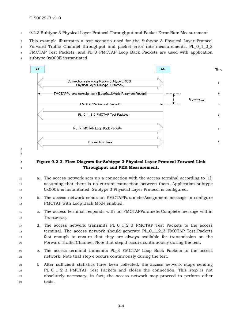
C.S0029-B v1.0
9-4
9.2.3 Subtype 3 Physical Layer Protocol Throughput and Packet Error Rate Measurement 1
This example illustrates a test scenario used for the Subtype 3 Physical Layer Protocol 2
Forward Traffic Channel throughput and packet error rate measurements. PL_0_1_2_3 3
FMCTAP Test Packets, and PL_3 FMCTAP Loop Back Packets are used with application 4
subtype 0x000E instantiated. 5
6
7
Figure 9.2-3. Flow Diagram for Subtype 3 Physical Layer Protocol Forward Link 8
Throughput and PER Measurement. 9
a. The access network sets up a connection with the access terminal according to [1], 10
assuming that there is no current connection between them. Application subtype 11
0x000E is instantiated. Subtype 3 Physical Layer Protocol is configured. 12
b. The access network sends an FMCTAPParameterAssignment message to configure 13
FMCTAP with Loop Back Mode enabled. 14
c. The access terminal responds with an FMCTAPParameterComplete message within 15
TFMCTAPConfig. 16
d. The access network transmits PL_0_1_2_3 FMCTAP Test Packets to the access 17
terminal. The access network should generate PL_0_1_2_3 FMCTAP Test Packets 18
fast enough to ensure that they are always available for transmission on the 19
Forward Traffic Channel. Note that step d occurs continuously during the test. 20
e. The access terminal transmits PL_3 FMCTAP Loop Back Packets to the access 21
network. Note that step e occurs continuously during the test. 22
f. After sufficient statistics have been collected, the access network stops sending 23
PL_0_1_2_3 FMCTAP Test Packets and closes the connection. This step is not 24
absolutely necessary; in fact, the access network may proceed to perform other 25
tests. 26
C.S0029-B v1.0
9-5
The access network uses the collected statistics at the access network to compute the 1
packet error rate and the average throughput as described in 9.3. 2
3
9.3 Computation of Forward Link Performance 4
In this section some sample Forward Link performance computations are described. It is 5
assumed that the Loop Back mode was enabled for collection of the statistics necessary for 6
throughput and packet error rate computation. 7
• Idle State ASP Change Rate (per second) (per sub-active set for multi-carrier 8
operation): 9
= IdleASPChange x 1000 / (IdleTime x 5 / 3) 10
• Connected State Serving Sector Change Rate (per second) (per sub-active set for 11
multi-carrier operation): 12
= ConnectedSSChange x 1000 / (ConnectedTime x 5 / 3) 13
• Control Channel packet error rate in the Idle State (%)(per sub-active set for multi-14
carrier operation): 15
= (1 – FirstSyncCCPkt / CCTime) x 100 16
• For Subtype 0 Physical Layer Protocol, throughput from a sector (kbps): 17
= FTAPMACPktRecd x 1024 / (FTAPTestTime x 16 x 5 / 3) 18
• For Subtype 0 and 1 Physical Layer Protocols, throughput from a sector (kbps): 19
= PL_0_1FETAPMACPktRecd x 1024 / (PL_0_1_2FETAPTestTime x 16 x 5 / 3) 20
• For Subtype 2 Physical Layer Protocol, throughput from a sector (kbps): 21
= ( ∑i
PL_2FETAPMACPktRecd[i] x FTC_PL_2PhysLayerPktSize[i]) / 22
(PL_0_1_2FETAPTestTime x 16 x 5 /3) 23
where FTC_PL_2PhysLayerPktSize[i] gives the number of bits in a Subtype 2 24
Physical Layer Protocol FTC packet with an FTC_PL_2PayloadSizeIndex i (see 25
4.9.3). 26
• For Subtype 3 Physical Layer Protocol, per sub-active set throughput from a sector 27
(kbps) for sub-active set index j: 28
= ( ∑i
PL_3FMCTAPMACPktRecd[i,j] x FTC_PL_3PhysLayerPktSize[i]) / 29
(PL_0_1_2_3FMCTAPTestTime x 16 x 5 /3) 30
where FTC_PL_3PhysLayerPktSize[i] gives the number of bits in a Subtype 3 31
Physical Layer Protocol FTC packet with an FTC_PL_3PayloadSizeIndex i (see 32
6.9.3). 33
• Throughput from all sub-active sets from a sector (kbps): 34
C.S0029-B v1.0
9-6
= ∑− setsactiveSubAll
Throughput per sub-active set from a sector (kbps) 1
2
• Throughput from all sectors (kbps): 3
= ∑AllSectors
Throughput from a sector (kbps) 4
• For Subtype 0 Physical Layer Protocol, throughput over transmitted slots from a 5
sector (kbps): 6
= FTAPMACPktRecd for the sector x 1024 / (FTAPPhysPktSlots for the sector x 5 7
/ 3) 8
• For Subtype 0 and 1 Physical Layer Protocols, throughput over transmitted slots 9
from a sector (kbps): 10
= PL_0_1FETAPMACPktRecd for the sector x 1024 / (PL_0_1FETAPPhysPktSlots 11
for the sector x 5 / 3) 12
• For Subtype 2 Physical Layer Protocol, throughput over transmitted slots from a 13
sector (kbps) : 14
= ∑i
PL_2FETAPMACPktRecd[i] for the sector x FTC_PL_2PhysLayerPktSize[i] / 15
∑i
(PL_2FETAPPhysPktSlots[i] for the sector x 5 / 3 16
where FTC_PL_2PhysLayerPktSize[i] gives the number of bits in a Subtype 2 17
Physical Layer Protocol packet with an FTC_PL2PayloadSizeIndex i (see 4.9.3). 18
• For Subtype 3 Physical Layer Protocol, throughput over transmitted slots from a 19
sector (kbps) for sub-active set index j: 20
= ∑i
PL_3FMCTAPMACPktRecd[i,j] for the sector x 21
FTC_PL_3PhysLayerPktSize[i] / ∑i
(PL_3FMCTAPPhysPktSlots[i,j] for the 22
sector x 5 / 3 23
where FTC_PL_3PhysLayerPktSize[i] gives the number of bits in a Subtype 3 24
Physical Layer Protocol packet with an FTC_PL3PayloadSizeIndex i (see 6.9.4). 25
• Throughput over transmitted slots from all sectors (kbps): 26
= ∑AllSectors
Throughput over transmitted slots from a sector (kbps) 27
• For Subtype 0 Physical Layer Protocol, forward link PER (%): 28
= (1 - ∑AllSectors
FTAPTestPktRecd / ∑AllSectors
FTAPTestPktSent ) x 100 29
• For Subtype 0, 1, and 2 Physical Layer Protocols, forward link PER (%): 30
C.S0029-B v1.0
9-7
= (1 - ∑AllSectors
PL_0_1_2FETAPTestPktRecd / ∑AllSectors
PL_0_1_2FETAPTestPktSent) x 1
100 2
• For Subtype 0, 1, 2 and 3 Physical Layer Protocols, forward link PER (%) per sub-3
active set: 4
• =PL_0_1_2_3FMCTAPTestPktRecd
PL_0_1_2_3FMCTAPTestPktSent1 100%
All Sectors
⎛ ⎞− ×⎜ ⎟
⎝ ⎠∑ For Subtype 0 Physical Layer 5
Protocol, reverse link quality over the test duration (%): 6
= (1 - FTAPLBPktRecd / FTAPLBPktSent ) x 100 7
• For Subtype 0 and 1 Physical Layer Protocols, reverse link quality over the test 8
duration (%): 9
= (1 – PL_0_1FETAPLBPktRecd / PL_0_1FETAPLBPktSent ) x 100 10
• For Subtype 2 Physical Layer Protocol, reverse link quality over the test duration 11
(%): 12
= (1 – PL_2FETAPLBPktRecd / PL_2FETAPLBPktSent ) x 100 13
• For Subtype 3 Physical Layer Protocol, reverse link quality over the test duration (%) 14
for reverse channel index j: 15
= (1 – PL_3FMCTAPLBPktRecd[j] / PL_3FMCTAPLBPktSent[j] ) x 100 16
9.4 Reverse Link Performance Tests 17
This section illustrates the use of RTAP, RETAP and RMCTAP procedures for three 18
scenarios, namely throughput and packet error rate measurement on the Subtype 0 19
Physical Layer Protocol Reverse Link, throughput and packet error rate measurement on 20
the Subtype 2 and 3 Physical Layer Protocol Reverse Link. 21
9.4.1 Subtype 0 Physical Layer Protocol Throughput and Packet Error Rate Measurement 22
This example illustrates a test scenario used for the Subtype 0 Physical Layer Protocol 23
Reverse Traffic Channel throughput and packet error rate measurements. RTAP signaling 24
messages and RTAP Test Packets are used if application subtype 0x0003 is instantiated. 25
RETAP signaling messages and PL_0_1 RETAP Test Packets are used if application subtype 26
0x000A is instantiated. 27
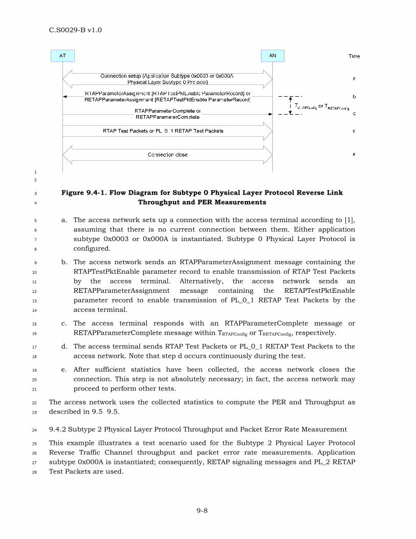
C.S0029-B v1.0
9-8
1
2
Figure 9.4-1. Flow Diagram for Subtype 0 Physical Layer Protocol Reverse Link 3
Throughput and PER Measurements 4
a. The access network sets up a connection with the access terminal according to [1], 5
assuming that there is no current connection between them. Either application 6
subtype 0x0003 or 0x000A is instantiated. Subtype 0 Physical Layer Protocol is 7
configured. 8
b. The access network sends an RTAPParameterAssignment message containing the 9
RTAPTestPktEnable parameter record to enable transmission of RTAP Test Packets 10
by the access terminal. Alternatively, the access network sends an 11
RETAPParameterAssignment message containing the RETAPTestPktEnable 12
parameter record to enable transmission of PL_0_1 RETAP Test Packets by the 13
access terminal. 14
c. The access terminal responds with an RTAPParameterComplete message or 15
RETAPParameterComplete message within TRTAPConfig or TRETAPConfig, respectively. 16
d. The access terminal sends RTAP Test Packets or PL_0_1 RETAP Test Packets to the 17
access network. Note that step d occurs continuously during the test. 18
e. After sufficient statistics have been collected, the access network closes the 19
connection. This step is not absolutely necessary; in fact, the access network may 20
proceed to perform other tests. 21
The access network uses the collected statistics to compute the PER and Throughput as 22
described in 9.5 9.5. 23
9.4.2 Subtype 2 Physical Layer Protocol Throughput and Packet Error Rate Measurement 24
This example illustrates a test scenario used for the Subtype 2 Physical Layer Protocol 25
Reverse Traffic Channel throughput and packet error rate measurements. Application 26
subtype 0x000A is instantiated; consequently, RETAP signaling messages and PL_2 RETAP 27
Test Packets are used. 28
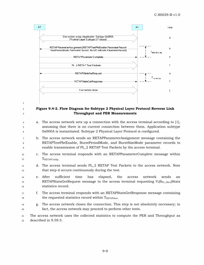
C.S0029-B v1.0
9-9
1
Figure 9.4-2. Flow Diagram for Subtype 2 Physical Layer Protocol Reverse Link 2
Throughput and PER Measurements 3
a. The access network sets up a connection with the access terminal according to [1], 4
assuming that there is no current connection between them. Application subtype 5
0x000A is instantiated. Subtype 2 Physical Layer Protocol is configured. 6
b. The access network sends an RETAPParameterAssignment message containing the 7
RETAPTestPktEnable, BurstPeriodMode, and BurstSizeMode parameter records to 8
enable transmission of PL_2 RETAP Test Packets by the access terminal. 9
c. The access terminal responds with an RETAPParameterComplete message within 10
TRETAPConfig. 11
d. The access terminal sends PL_2 RETAP Test Packets to the access network. Note 12
that step d occurs continuously during the test. 13
e. After sufficient time has elapsed, the access network sends an 14
RETAPStatsGetRequest message to the access terminal requesting Vi(SPL_2Rev)Stats 15
statistics record. 16
f. The access terminal responds with an RETAPStatsGetResponse message containing 17
the requested statistics record within TRETAPStat. 18
g. The access network closes the connection. This step is not absolutely necessary; in 19
fact, the access network may proceed to perform other tests. 20
The access network uses the collected statistics to compute the PER and Throughput as 21
described in 9.59.5. 22
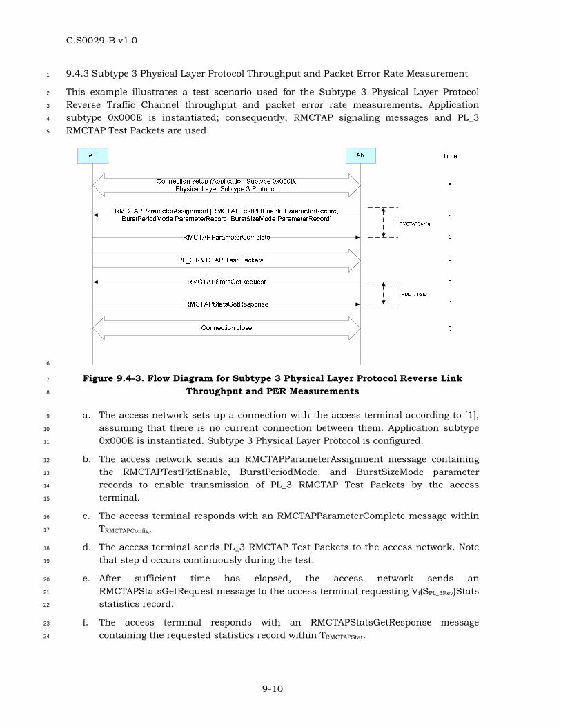
C.S0029-B v1.0
9-10
9.4.3 Subtype 3 Physical Layer Protocol Throughput and Packet Error Rate Measurement 1
This example illustrates a test scenario used for the Subtype 3 Physical Layer Protocol 2
Reverse Traffic Channel throughput and packet error rate measurements. Application 3
subtype 0x000E is instantiated; consequently, RMCTAP signaling messages and PL_3 4
RMCTAP Test Packets are used. 5
6
Figure 9.4-3. Flow Diagram for Subtype 3 Physical Layer Protocol Reverse Link 7
Throughput and PER Measurements 8
a. The access network sets up a connection with the access terminal according to [1], 9
assuming that there is no current connection between them. Application subtype 10
0x000E is instantiated. Subtype 3 Physical Layer Protocol is configured. 11
b. The access network sends an RMCTAPParameterAssignment message containing 12
the RMCTAPTestPktEnable, BurstPeriodMode, and BurstSizeMode parameter 13
records to enable transmission of PL_3 RMCTAP Test Packets by the access 14
terminal. 15
c. The access terminal responds with an RMCTAPParameterComplete message within 16
TRMCTAPConfig. 17
d. The access terminal sends PL_3 RMCTAP Test Packets to the access network. Note 18
that step d occurs continuously during the test. 19
e. After sufficient time has elapsed, the access network sends an 20
RMCTAPStatsGetRequest message to the access terminal requesting Vi(SPL_3Rev)Stats 21
statistics record. 22
f. The access terminal responds with an RMCTAPStatsGetResponse message 23
containing the requested statistics record within TRMCTAPStat. 24
C.S0029-B v1.0
9-11
g. The access network closes the connection. This step is not absolutely necessary; in 1
fact, the access network may proceed to perform other tests. 2
The access network uses the collected statistics to compute the PER and Throughput as 3
described in 9.5. 4
9.5 Computation of Reverse Link Performance 5
In this section some sample Reverse Link performance computations are described. In the 6
following, PhysLayerPktSize[i] gives the number of bits in a Physical Layer packet [1] at a 7
rate with RateIndex i (see Table 3.8.1.2-1). RTC_PL_0_1PhysLayerPktSize[i] gives the 8
number of bits in a Physical Layer packet at a rate with RTC_PL_0_1RateIndex i (see Table 9
5.8.1.2-1). RTC_PL_2PhysLayerPktSize[i] and RTC_PL_3PhysLayerPktSize[i] gives the 10
number of bits in a Physical Layer packet at a payload size with RTC_PL_2PayloadSizeIndex 11
and RTC_PL_3PayloadSizeIndex i (see Table 5.8.1.3-1 and Table 7.8.1.3-1). 12
• For Subtype 0 Physical Layer Protocol, throughput (kbps) for a rate with RateIndex 13
i: 14
= RTCMACPktRecd[i] x PhysLayerPktSize[i] / (RTAPTestTime x 16 x 5 /3) 15
• For Subtype 0 and 1 Physical Layer Protocols, throughput (kbps) for a rate with 16
RTC_PL_0_1RateIndex i: 17
= PL_0_1RTCMACPktRecd[i] x RTC_PL_0_1PhysLayerPktSize[i] / 18
(PL_0_1RETAPTestTime x 16 x 5 /3) 19
• For Subtype 2 Physical Layer Protocol, throughput (kbps) for a payload size with 20
RTC_PL_2PayloadSizeIndex i: 21
= PL_2RTCMACPktRecd[i] x RTC_PL_2PhysLayerPktSize[i] / 22
(PL_2RETAPTestTime x 4 x 5 / 3) 23
• For Subtype 3 Physical Layer Protocol, throughput (kbps) for a payload size with 24
RTC_PL_3PayloadSizeIndex i for reverse link with index j: 25
= PL_3RTCMACPktRecd[i,j] x RTC_PL_3PhysLayerPktSize[i] / 26
(PL_2_3RMCTAPTestTime x 4 x 5 / 3) 27
• For Subtype 0 Physical Layer Protocol, overall throughput (kbps): 28
= (∑i
RTCMACPktRecd[i] x PhysLayerPktSize[i]) / (RTAPTestTime x 16 x 5 /3) 29
• For Subtype 0 and 1 Physical Layer Protocols, overall throughput (kbps): 30
= ( ∑i
PL_0_1RTCMACPktRecd[i] x RTC_PL_0_1PhysLayerPktSize[i]) / 31
(PL_0_1RETAPTestTime x 16 x 5 /3) 32
• For Subtype 2 Physical Layer Protocol, overall throughput (kbps): 33
= ( ∑i
PL_2RTCMACPktRecd[i] x RTC_PL_2PhysLayerPktSize[i]) / 34
(PL_2RETAPTestTime x 4 x 5 /3) 35
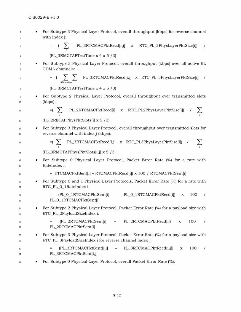
C.S0029-B v1.0
9-12
• For Subtype 3 Physical Layer Protocol, overall throughput (kbps) for reverse channel 1
with index j: 2
= ( ∑i
PL_3RTCMACPktRecd[i,j] x RTC_PL_3PhysLayerPktSize[i]) / 3
(PL_3RMCTAPTestTime x 4 x 5 /3) 4
• For Subtype 3 Physical Layer Protocol, overall throughput (kbps) over all active RL 5
CDMA channels: 6
= ( ∑∑icarriersall
PL_3RTCMACPktRecd[i,j] x RTC_PL_3PhysLayerPktSize[i]) / 7
(PL_3RMCTAPTestTime x 4 x 5 /3) 8
• For Subtype 2 Physical Layer Protocol, overall throughput over transmitted slots 9
(kbps): 10
=( ∑i
PL_2RTCMACPktRecd[i] x RTC_PL2PhysLayerPktSize[i]) / ∑i
11
(PL_2RETAPPhysPktSlots[i] x 5 /3) 12
• For Subtype 3 Physical Layer Protocol, overall throughput over transmitted slots for 13
reverse channel with index j (kbps): 14
=( ∑i
PL_3RTCMACPktRecd[i,j] x RTC_PL3PhysLayerPktSize[i]) / ∑i
15
(PL_3RMCTAPPhysPktSlots[i,j] x 5 /3) 16
• For Subtype 0 Physical Layer Protocol, Packet Error Rate (%) for a rate with 17
RateIndex i: 18
= (RTCMACPktSent[i] – RTCMACPktRecd[i]) x 100 / RTCMACPktSent[i] 19
• For Subtype 0 and 1 Physical Layer Protocols, Packet Error Rate (%) for a rate with 20
RTC_PL_0_1RateIndex i: 21
= (PL_0_1RTCMACPktSent[i] – PL_0_1RTCMACPktRecd[i]) x 100 / 22
PL_0_1RTCMACPktSent[i] 23
• For Subtype 2 Physical Layer Protocol, Packet Error Rate (%) for a payload size with 24
RTC_PL_2PayloadSizeIndex i: 25
= (PL_2RTCMACPktSent[i] – PL_2RTCMACPktRecd[i]) x 100 / 26
PL_2RTCMACPktSent[i] 27
• For Subtype 3 Physical Layer Protocol, Packet Error Rate (%) for a payload size with 28
RTC_PL_3PayloadSizeIndex i for reverse channel index j: 29
= (PL_3RTCMACPktSent[i,j] – PL_3RTCMACPktRecd[i,j]) x 100 / 30
PL_3RTCMACPktSent[i,j] 31
• For Subtype 0 Physical Layer Protocol, overall Packet Error Rate (%): 32
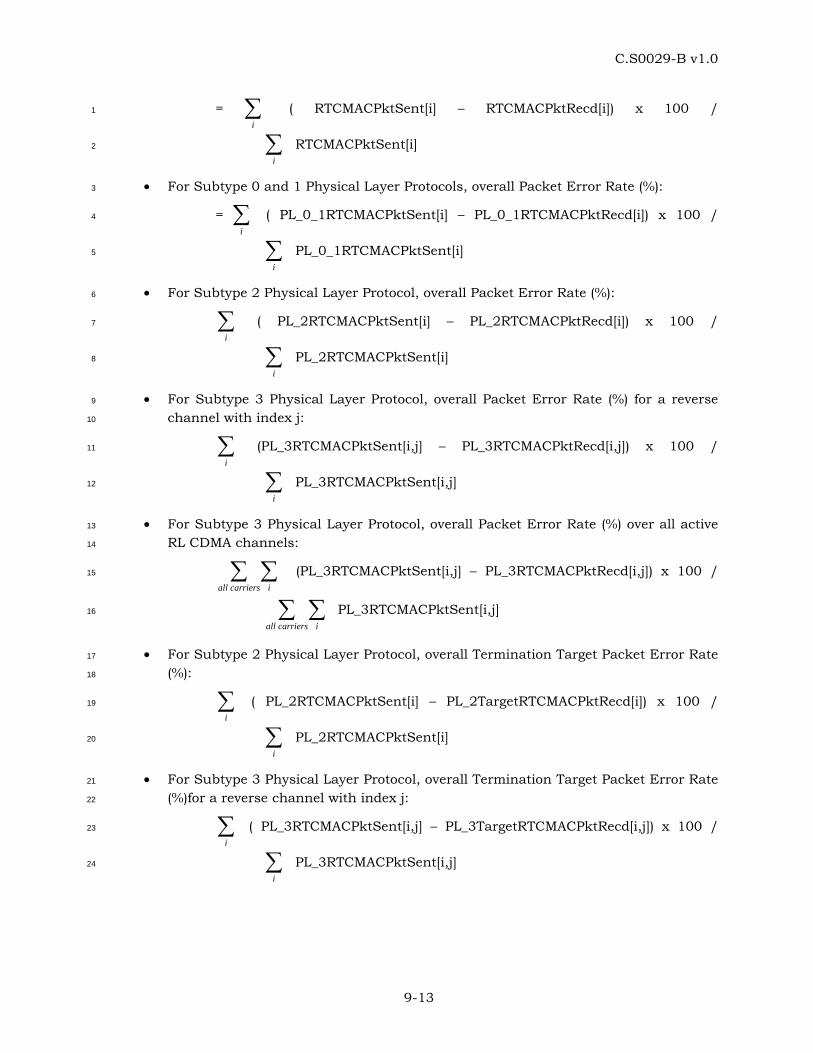
C.S0029-B v1.0
9-13
= ∑i
( RTCMACPktSent[i] – RTCMACPktRecd[i]) x 100 / 1
∑i
RTCMACPktSent[i] 2
• For Subtype 0 and 1 Physical Layer Protocols, overall Packet Error Rate (%): 3
= ∑i
( PL_0_1RTCMACPktSent[i] – PL_0_1RTCMACPktRecd[i]) x 100 / 4
∑i
PL_0_1RTCMACPktSent[i] 5
• For Subtype 2 Physical Layer Protocol, overall Packet Error Rate (%): 6
∑i
( PL_2RTCMACPktSent[i] – PL_2RTCMACPktRecd[i]) x 100 / 7
∑i
PL_2RTCMACPktSent[i] 8
• For Subtype 3 Physical Layer Protocol, overall Packet Error Rate (%) for a reverse 9
channel with index j: 10
∑i
(PL_3RTCMACPktSent[i,j] – PL_3RTCMACPktRecd[i,j]) x 100 / 11
∑i
PL_3RTCMACPktSent[i,j] 12
• For Subtype 3 Physical Layer Protocol, overall Packet Error Rate (%) over all active 13
RL CDMA channels: 14
∑∑icarriersall
(PL_3RTCMACPktSent[i,j] – PL_3RTCMACPktRecd[i,j]) x 100 / 15
∑∑icarriersall
PL_3RTCMACPktSent[i,j] 16
• For Subtype 2 Physical Layer Protocol, overall Termination Target Packet Error Rate 17
(%): 18
∑i
( PL_2RTCMACPktSent[i] – PL_2TargetRTCMACPktRecd[i]) x 100 / 19
∑i
PL_2RTCMACPktSent[i] 20
• For Subtype 3 Physical Layer Protocol, overall Termination Target Packet Error Rate 21
(%)for a reverse channel with index j: 22
∑i
( PL_3RTCMACPktSent[i,j] – PL_3TargetRTCMACPktRecd[i,j]) x 100 / 23
∑i
PL_3RTCMACPktSent[i,j] 24
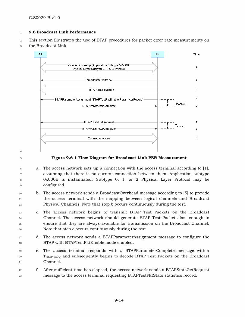
C.S0029-B v1.0
9-14
9.6 Broadcast Link Performance 1
This section illustrates the use of BTAP procedures for packet error rate measurements on 2
the Broadcast Link. 3
4
Figure 9.6-1 Flow Diagram for Broadcast Link PER Measurement 5
a. The access network sets up a connection with the access terminal according to [1], 6
assuming that there is no current connection between them. Application subtype 7
0x000B is instantiated. Subtype 0, 1, or 2 Physical Layer Protocol may be 8
configured. 9
b. The access network sends a BroadcastOverhead message according to [5] to provide 10
the access terminal with the mapping between logical channels and Broadcast 11
Physical Channels. Note that step b occurs continuously during the test. 12
c. The access network begins to transmit BTAP Test Packets on the Broadcast 13
Channel. The access network should generate BTAP Test Packets fast enough to 14
ensure that they are always available for transmission on the Broadcast Channel. 15
Note that step c occurs continuously during the test. 16
d. The access network sends a BTAPParameterAssignment message to configure the 17
BTAP with BTAPTestPktEnable mode enabled. 18
e. The access terminal responds with a BTAPParameterComplete message within 19
TBTAPConfig and subsequently begins to decode BTAP Test Packets on the Broadcast 20
Channel. 21
f. After sufficient time has elapsed, the access network sends a BTAPStatsGetRequest 22
message to the access terminal requesting BTAPTestPktStats statistics record. 23
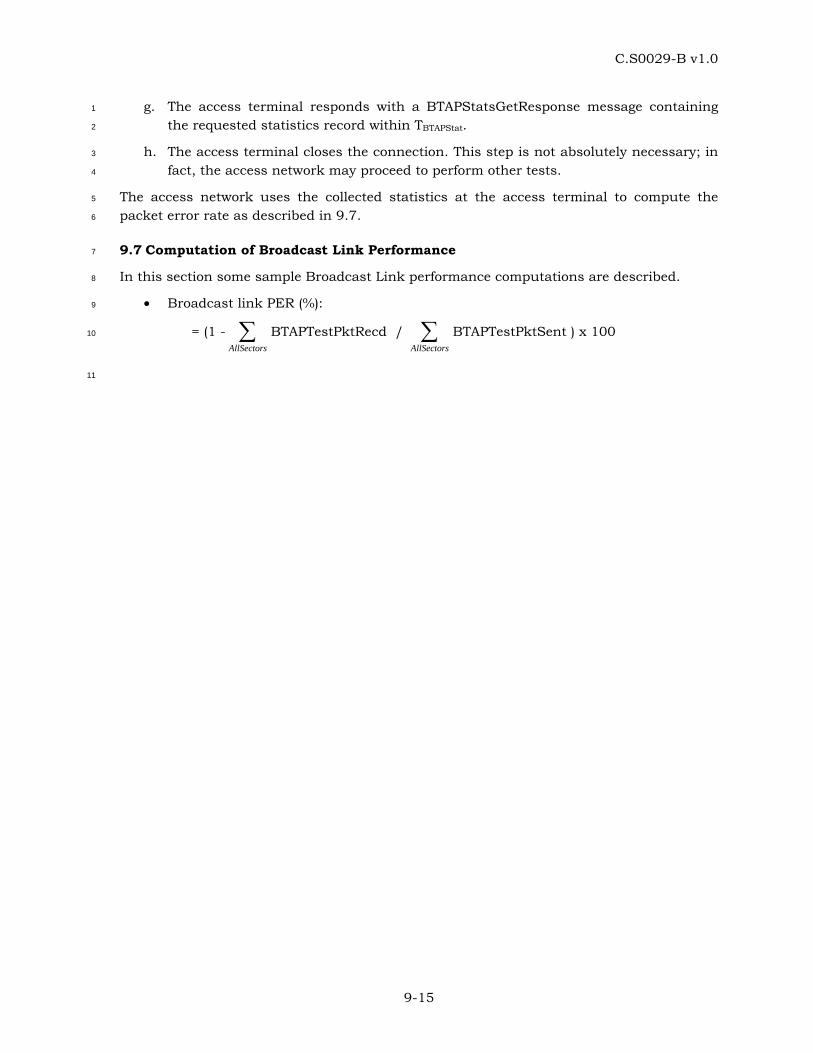
C.S0029-B v1.0
9-15
g. The access terminal responds with a BTAPStatsGetResponse message containing 1
the requested statistics record within TBTAPStat. 2
h. The access terminal closes the connection. This step is not absolutely necessary; in 3
fact, the access network may proceed to perform other tests. 4
The access network uses the collected statistics at the access terminal to compute the 5
packet error rate as described in 9.7. 6
9.7 Computation of Broadcast Link Performance 7
In this section some sample Broadcast Link performance computations are described. 8
• Broadcast link PER (%): 9
= (1 - ∑AllSectors
BTAPTestPktRecd / ∑AllSectors
BTAPTestPktSent ) x 100 10
11