Embed Size (px)
Citation preview
Refer to “Notice” in the preface of ARIB TR-T12 for Copyrights.
ARIB TR-T12-25.999 V7.1.0
High Speed Packet Access (HSPA)
evolution; Frequency Division Duplex (FDD) (Release 7)
3GPP TR 25.999 V7.1.0 (2008-03)Technical Report
3rd Generation Partnership Project;Technical Specification Group Radio Access Network;
High Speed Packet Access (HSPA) evolution; Frequency Division Duplex (FDD)
(Release 7)
The present document has been developed within the 3rd Generation Partnership Project (3GPP TM) and may be further elaborated for the purposes of 3GPP. The present document has not been subject to any approval process by the 3GPP Organizational Partners and shall not be implemented. This Specification is provided for future development work within 3GPP only. The Organizational Partners accept no liability for any use of this Specification.Specifications and reports for implementation of the 3GPP TM system should be obtained via the 3GPP Organizational Partners' Publications Offices.
3GPP
3GPP TR 25.999 V7.0.1 (2007-12)2Release 7
Keywords UMTS, radio
3GPP
Postal address
3GPP support office address 650 Route des Lucioles - Sophia Antipolis
Valbonne - FRANCE Tel.: +33 4 92 94 42 00 Fax: +33 4 93 65 47 16
Internet http://www.3gpp.org
Copyright Notification
No part may be reproduced except as authorized by written permission. The copyright and the foregoing restriction extend to reproduction in all media.
© 2008, 3GPP Organizational Partners (ARIB, ATIS, CCSA, ETSI, TTA, TTC).
All rights reserved.
3GPP
3GPP TR 25.999 V7.0.1 (2007-12)3Release 7
Contents Foreword.............................................................................................................................................................5 1 Scope ........................................................................................................................................................6 2 References ................................................................................................................................................6 3 Definitions, symbols and abbreviations ...................................................................................................6 3.1 Definitions ......................................................................................................................................................... 6 3.2 Abbreviations..................................................................................................................................................... 6 4 Introduction ..............................................................................................................................................7 5 Objectives.................................................................................................................................................7 6 Constraints and requirements ...................................................................................................................8 6.1 Constraints ......................................................................................................................................................... 8 6.2 Requirements ..................................................................................................................................................... 8 6.2.1 Requirements for the UTRAN architecture.................................................................................................. 8 6.2.2 Requirements for the UTRA ........................................................................................................................ 9 7 Technical Proposals and Assessment .......................................................................................................9 7.1 Architectural solutions ..................................................................................................................................... 11 7.1.1 Current Release 6 Architecture - Alt 1 ....................................................................................................... 11 7.1.2 Iu with enhanced SRNC separate from the enhanced collapsed CRNC/DRNC/Node B – Alt 2 ............... 12 7.1.2.1 General description............................................................................................................................... 12 7.1.2.2 User Plane............................................................................................................................................. 13 7.1.2.3 Control Plane (Radio part).................................................................................................................... 13 7.1.2.4 Control Plane (Interface part) ............................................................................................................... 14 7.1.2.5 Support of legacy UE.......................................................................................................................... 14 7.1.2.6 Support of legacy networks .................................................................................................................. 15 7.1.2.7 Additional Information ......................................................................................................................... 16 7.1.2.8 Open issues........................................................................................................................................... 17 7.1.3 PS User Plane /Control Plane split, CP functions in RNC, direct UP tunnel PS CN – Node B – Alt 3 ..... 18 7.1.3.1 General description............................................................................................................................... 18 7.1.3.2 Protocol architecture............................................................................................................................. 19 7.1.3.3 Control plane ........................................................................................................................................ 19 7.1.3.4 Support of legacy UEs.......................................................................................................................... 20 7.1.3.5 Interworking with legacy architecture .................................................................................................. 20 7.1.4 Iu with RNC U-Plane & C-Plane functions in Node-B – Alt 4.................................................................. 20 7.1.4.1 User plane............................................................................................................................................. 21 7.1.4.2 Control plane ........................................................................................................................................ 22 7.1.4.3 Support of legacy UEs.......................................................................................................................... 22 7.1.4.4 CS Service in stand-alone scenario....................................................................................................... 22 7.1.4.4.1 CS CN domain interworking with Gs interface deployed:.............................................................. 22 7.1.4.4.2 CS CN domain interworking without deployed Gs interface: ........................................................ 23 7.1.4.5 Interworking with legacy architecture .................................................................................................. 24 7.1.4.6 Paging................................................................................................................................................... 24 7.1.4.7 Soft Handover for Signalling Radio Bearers: ....................................................................................... 24 7.1.4.8 CS Service in Carrier Sharing scenario ................................................................................................ 25 7.1.4.8.1 Evaluation Table ............................................................................................................................. 25 7.1.4.8.2 Relocation to Legacy RNC (Iur-based solution)............................................................................. 26 7.1.4.9 Iu with RNC U-Plane & C-Plane functions in Node-B: Iu CS support permutations comparison....... 30 7.1.4.10 Load Balancing between the Legacy and HSPA+ Network ................................................................. 31 7.1.4.11 Security and ciphering .......................................................................................................................... 31 7.1.4.12 Open Issues........................................................................................................................................... 31 7.1.5 S1 interface architecture, i.e. SAE architecture with RLC (no-ciphering) & RRC in Node B................. 31 7.1.5.1 Non-soft handover approach................................................................................................................. 31 7.1.5.1.1 Description of the architecture (from figure 7.1.5-1)...................................................................... 32 7.1.5.2 Soft handover approach ........................................................................................................................ 33 7.1.5.3 Support of legacy UEs.......................................................................................................................... 33
3GPP
3GPP TR 25.999 V7.0.1 (2007-12)4Release 7
7.1.6 Evolved HSPA (Collapsed Architecture) with SHO – Considerations with connectivity to evolved CN .............................................................................................................................................................. 34
7.1.6.1 General ................................................................................................................................................. 34 7.1.6.2 Collapsed Architecture with connectivity to the evolved CN Approach.............................................. 34 7.1.6.3 Pictorial Representation of Collapsed Architecture Approach ............................................................. 34 7.1.6.4 Description of architecture ................................................................................................................... 35 7.1.6.5 Open issues........................................................................................................................................... 36 7.1.7 Enhanced SRNS relocation procedure...................................................................................................... 37 7.1.7.1 Network-controlled Mobility................................................................................................................ 37 7.1.7.2 UE-controlled Mobility ........................................................................................................................ 39 7.1.7.3 Open issues........................................................................................................................................... 40 7.2 Interworking with legacy UTRAN nodes ........................................................................................................ 40 7.2.1 Collapsing legacy SRNC and CRNC into Node B..................................................................................... 40 7.2.2 Collapsing only legacy CRNC into Node B............................................................................................... 41 7.2.3 Not collapsing any of the legacy CS network into the Node B .................................................................. 42 7.3 Support of UL Macro Diversity Combining .................................................................................................... 44 7.3.1 Flat evolved UTRAN architectures ............................................................................................................ 44 7.4 RNC ID Extension ........................................................................................................................................... 46 7.4.1 Solution for RNC-ID Extension ................................................................................................................. 46 7.4.2 Specification Impact................................................................................................................................... 47 7.4.3 Rules for Configuration.............................................................................................................................. 47 7.4.4 Configuration Example .............................................................................................................................. 51 7.5 Layer 2 Enhancements..................................................................................................................................... 52 7.5.1 Flexible RLC PDU sizes and MAC-hs segmentation ................................................................................ 52 7.5.1.1 General description............................................................................................................................... 52 7.5.1.2 Layer 2 without ARQ sub-layer ........................................................................................................... 52 7.5.1.3 Layer 2 with new ARQ sub-layer ......................................................................................................... 52 7.6 UL Enhancements............................................................................................................................................ 53 7.6.1 Enhancement for RoT control for VoIP ..................................................................................................... 53 7.7 Radio Related Enhancements .......................................................................................................................... 53 7.7.1 Multiple Input / Multiple Output (MIMO)................................................................................................. 53 7.7.2 Continuous Connectivity for Packet Data Users (CPC) ............................................................................. 54 7.7.3 Downlink Higher Order Modulation using 64 QAM for HSDPA ............................................................. 54 7.7.4 Uplink Higher Order Modulation using 16 QAM for HSUPA .................................................................. 55 7.7.5 Improved Layer-2 Support for High Data rates.......................................................................................... 55 7.7.6 Enhanced Cell FACH................................................................................................................................. 56 7.7.7 Interference Cancellation (Further improved minimum performance requirements for
UMTS/HSDPA UE)................................................................................................................................... 56 7.8 MBMS ............................................................................................................................................................. 57 8 Conclusions and Recommendations.......................................................................................................57 8.1 Independence Between Radio Features and HSPA Architecture Evolution .................................................... 57 8.2 IP Multicast for MBMS User Plane................................................................................................................. 58 8.3 Carrier sharing scenario for architecture alternative Iu with RNC U-Plane & C-Plane functions in Node-
B ...................................................................................................................................................................... 58
Annex A: Change history ......................................................................................................................59
3GPP
3GPP TR 25.999 V7.0.1 (2007-12)5Release 7
Foreword This Technical Report has been produced by the 3rd Generation Partnership Project (3GPP).
The contents of the present document are subject to continuing work within the TSG and may change following formal TSG approval. Should the TSG modify the contents of the present document, it will be re-released by the TSG with an identifying change of release date and an increase in version number as follows:
Version x.y.z
where:
x the first digit:
1 presented to TSG for information;
2 presented to TSG for approval;
3 or greater indicates TSG approved document under change control.
y the second digit is incremented for all changes of substance, i.e. technical enhancements, corrections, updates, etc.
z the third digit is incremented when editorial only changes have been incorporated in the document.
3GPP
3GPP TR 25.999 V7.0.1 (2007-12)6Release 7
1 Scope The present document has been produced in the scope of the study item on "HSPA Evolution" [2]. The objective of the study item is to develop a framework for the evolution of the FDD mode of the 3GPP HSPA WCDMA-based radio-access technology beyond Release 7.
The present document lists the constraints for the FDD HSPA Evolution beyond release 7 and an assessment of technical proposals and their respective, achievable performance and complexity.
2 References The following documents contain provisions which, through reference in this text, constitute provisions of the present document.
• References are either specific (identified by date of publication, edition number, version number, etc.) or non-specific.
• For a specific reference, subsequent revisions do not apply.
• For a non-specific reference, the latest version applies. In the case of a reference to a 3GPP document (including a GSM document), a non-specific reference implicitly refers to the latest version of that document in the same Release as the present document.
[1] 3GPP TR 21.905: "Vocabulary for 3GPP Specifications".
[2] 3GPP TD RP-060217: "Work Item Description on Scope of future FDD HSPA Evolution".
Suppote Team note: Reference [2] is not legitimate.
3 Definitions, symbols and abbreviations
3.1 Definitions For the purposes of the present document, the terms and definitions given in TR 21.905 [1] and the following apply. A term defined in the present document takes precedence over the definition of the same term, if any, in TR 21.905 [1].
HSPA: In the present document, the acronym HSPA (High Speed Packet Access) is used to qualify the FDD mode features HSDPA (High Speed Downlink Packet Access) and Enhanced Uplink as defined in the Release 7 version of the 3GPP Specifications.
Backward Compatibility: In the present document, Backward Compatibility means the ability of an HSPA infrastructure to simultaneously allocate radio resources on one single carrier to post-release 7 terminals and terminals compliant with previous releases of the 3GPP specifications without performances degradation for either type of terminal. It is understood that in that case the performance enhancements targeted in this document would only apply to post-release 7 terminals and that the full potential of system performance enhancements would only be achievable if all terminals operating simultaneously on a single carrier were post-release 7 terminals.
3.2 Abbreviations For the purposes of the present document, the abbreviations given in TR 21.905 [1] and the following apply. An abbreviation defined in the present document takes precedence over the definition of the same abbreviation, if any, in TR 21.905 [1].
CAPEX Capital expenditure CS Circuit Switched DRX Discontinuous Reception
3GPP
3GPP TR 25.999 V7.0.1 (2007-12)7Release 7
HSPA High Speed Packet Access LTE: Long Term Evolution MIMO Multiple Input Multiple Output NAS Non Access Stratum OPEX Operational expenditure QoS Quality of Service PS Packet Switched TCP Transmission Control Protocol UE User Equipment
4 Introduction The Study Item Description on "HSPA Evolution" [2] was approved by the 3GPP TSG RAN #31 plenary meeting in March 2006.
The importance of on-going and future efforts to enhance the capabilities and performance of HSPA-based radio networks is widely recognised by 3GPP operators. HSPA networks will form an integral part of future 3G systems and as they evolve, should provide a smooth migration path towards LTE. HSPA operators are just as interested in the potential performance and cost savings which may be achieved through HSPA Evolution as they are in the future LTE system.
Critical elements of such evolution should include reduced latency, higher user data rates, improved system capacity and coverage and reduced cost for the operator while maintaining the highest possible level of backward compatibility.
5 Objectives Beyond Release 7, the following elements should be considered as guiding principles for HSPA Evolution:
1. HSPA Spectrum Efficiency, Peak Data Rate and Latency should continue to evolve favourably. The tradeoffs necessary to achieve performance comparable to LTE in 5 MHz should be analyzed;
2. HSPA and its evolution should facilitate the joint technology operation with LTE and offer a smooth migration path towards LTE (Long Term Evolution). The possibility to adopt common elements or a common functional split with LTE and the possibility to re-use the evolved Core Network defined as part of the System Architecture Evolution (SAE) study should be analyzed as well;
3. Evolved HSPA should be able to operate as a packet-only network based on utilization of the high speed data channels only (HS-DSCH, E-DCH and associated channels);
4. HSPA Evolution shall be backward compatible in the sense that legacy terminals (R99-DCH and HSPA mobiles) shall be able to share the same carrier with terminals implementing the latest features of the HSPA Evolution track without any performance degradation;
5. Ideally, existing infrastructure should only need a simple upgrade to support the features defined as part of the HSPA Evolution.
Thus, the study should focus on improving the system performances for services delivered through the PS-domain including voice and multimedia conversational services.
In relation to this study item, TSG-RAN should establish a reference performance set for HSPA release 7. Rather than relying on new simulation results, it is recommended that this performance set is derived from on-going activities related to the performance evaluation of new enhancements like HSDPA MIMO or LTE. This reference performance set should be used to set the absolute performance targets for HSPA Evolution and to evaluate the potential improvements provided by solutions proposed in the scope of the study.
3GPP
3GPP TR 25.999 V7.0.1 (2007-12)8Release 7
6 Constraints and requirements NOTE: This chapter will capture text on the constraints for HSPA evolution including on legacy issues, backward
compatibility, architecture, impact on LTE, Node B and UTRA, software and hardware upgrades, complexity issues, acceptable impacts on UE's, protocol reuse/requirements, signalling and physical channel limitations, etc.
6.1 Constraints a) HSPA Evolution should be capable of being implemented through a re-use of the release 7 RAN architecture.
However, proposals to modify the RAN architecture should also be considered within the scope of HSPA Evolution, provided full interworking to a legacy release 7 architecture is supported.
b) The RAN-CN functional split can be reviewed providing that it results in significant performance and/or improvements and facilitate the migration towards LTE/SAE without significant complexity increase.
c) Evolved HSPA should have a minimum impact on Node Bs, to allow for simple upgrades; Reuse of the existing Node B hardware by HSPA Evolution is essential. This does not preclude hardware upgrades to support additional functionality (e.g. to increase processing power, RNC functionality, etc.).
d) Evolved HSPA protocol architecture shall have minimum impact on UEs especially in terms of complexity, to allow for easy introduction.
e) R99-DCH and legacy HSPA UEs shall be able to share the same carrier with terminals implementing the latest features of the HSPA Evolution without any performance degradation.
f) Intra- and inter-system mobility performance shall be no worse than R7.
6.2 Requirements
6.2.1 Requirements for the UTRAN architecture a) Should provide a low complexity, low cost and smooth migration of HSPA towards evolved UMTS (SAE/LTE).
b) Should reduce user plane latency to legacy (R5,6 & 7) & beyond R7 terminals.
c) Should reduce control plane latency to beyond R7 terminals and, if low complexity cost effective means can be found, also to legacy terminals.
d) Simplification and reduction of the number of nodes should be considered.
e) Connection of evolved HSPA RAN to SAE CN (UP &/or CP) should be considered.
f) Should consider mobility between non 3GPP access systems and evolved HSPA.
g) Should consider IW with CS domain to support legacy CS services.
h) Should consider proposals to lower backhaul costs.
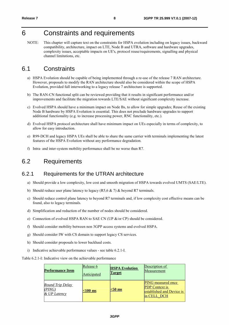
i) Indicative achievable performance values - see table 6.2.1-I.
Table 6.2.1-I: Indicative view on the achievable performance
Performance Item Release 6
Anticipated HSPA Evolution Target
Description of Measurement
Round Trip Delay (PING) & UP Latency
<100 ms <50 ms
PING measured once PDP Context is established and Device is in CELL_DCH
3GPP
3GPP TR 25.999 V7.0.1 (2007-12)9Release 7
Packet Call Set Up
May exceed 1000 ms
<500 ms
Cold start. Measured from the RRC Connection Request sent by a Terminal previously in PMM_Idle to the completion of the PDP Context Establishment Procedure
CP Latency Dormant to Active
May exceed 1000 ms
<100 ms
Time needed to transition the UE from a Dormant state like CELL_PCH or URA_PCH to CELL_DCH (Active with a RAB/RB set Up) with or without having to (re-) establish a PDP Context
Note: The values in this table are indicative views of how much HSPA could be improved at the time of starting the study. These values are for information only.
6.2.2 Requirements for the UTRA a) Changes that deliver higher spectrum efficiency should be considered, within the constraints specified in the
clause 8.
b) Should reduce user plane latency to legacy (R5,6 & 7) & beyond R7 terminals.
c) Should reduce control plane latency to beyond R7 terminals and, if low complexity cost effective means can be found, also to legacy terminals.
d) Should consider how to provide efficient QoS support for all traffic classes preferably in a manner that is backwards compatible with legacy terminals.
e) Should consider changes that, where it makes sense, deliver benefits to legacy terminals as well as beyond R7 terminals.
f) Any changes to the terminal should maximally build on the extensive developments and testing efforts of R5, 6 & 7.
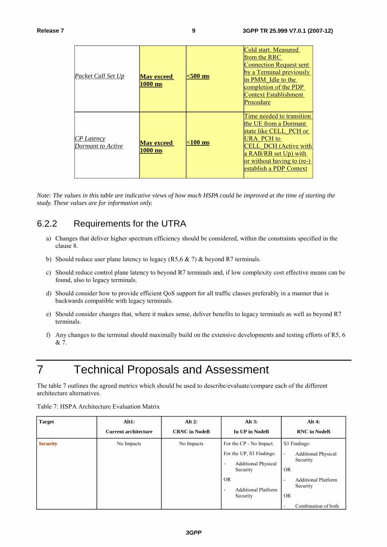
7 Technical Proposals and Assessment The table 7 outlines the agreed metrics which should be used to describe/evaluate/compare each of the different architecture alternatives.
Table 7: HSPA Architecture Evaluation Matrix
Target Alt1:
Current architecture
Alt 2:
CRNC in NodeB
Alt 3:
Iu UP in NodeB
Alt 4:
RNC in NodeB
Security
No Impacts No Impacts For the CP - No Impact.
For the UP, S3 Findings:
- Additional Physical Security
OR
- Additional Platform Security
S3 Findings:
- Additional Physical Security
OR
- Additional Platform Security
OR
- Combination of both
3GPP
3GPP TR 25.999 V7.0.1 (2007-12)10Release 7
OR
- OR Combination of both required
required
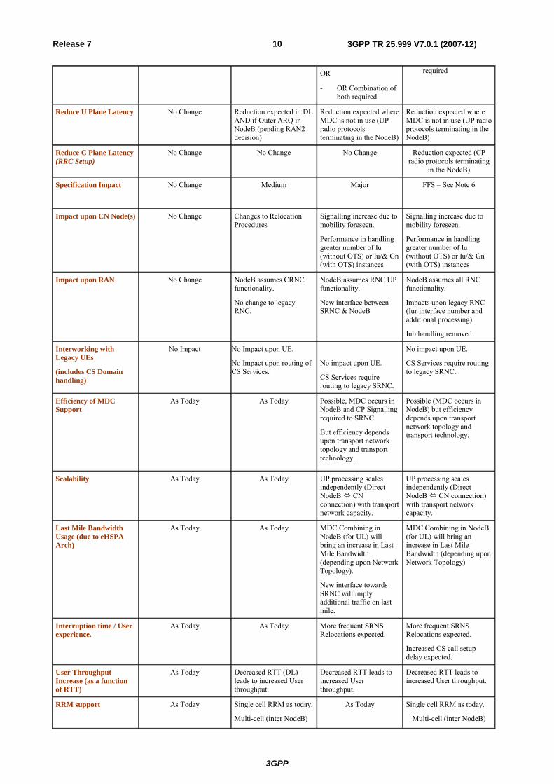
Reduce U Plane Latency No Change Reduction expected in DL AND if Outer ARQ in NodeB (pending RAN2 decision)
Reduction expected where MDC is not in use (UP radio protocols terminating in the NodeB)
Reduction expected where MDC is not in use (UP radio protocols terminating in the NodeB)
Reduce C Plane Latency (RRC Setup)
No Change No Change No Change
Reduction expected (CP radio protocols terminating
in the NodeB)
Specification Impact No Change Medium Major FFS – See Note 6
Impact upon CN Node(s) No Change Changes to Relocation Procedures
Signalling increase due to mobility foreseen.
Performance in handling greater number of Iu (without OTS) or Iu/& Gn (with OTS) instances
Signalling increase due to mobility foreseen.
Performance in handling greater number of Iu (without OTS) or Iu/& Gn (with OTS) instances
Impact upon RAN No Change NodeB assumes CRNC functionality.
No change to legacy RNC.
NodeB assumes RNC UP functionality.
New interface between SRNC & NodeB
NodeB assumes all RNC functionality.
Impacts upon legacy RNC (Iur interface number and additional processing).
Iub handling removed
Interworking with Legacy UEs
(includes CS Domain handling)
No Impact No Impact upon UE.
No Impact upon routing of CS Services.
No impact upon UE.
CS Services require routing to legacy SRNC.
No impact upon UE.
CS Services require routing to legacy SRNC.
Efficiency of MDC Support
As Today As Today Possible, MDC occurs in NodeB and CP Signalling required to SRNC.
But efficiency depends upon transport network topology and transport technology.
Possible (MDC occurs in NodeB) but efficiency depends upon transport network topology and transport technology.
Scalability As Today As Today UP processing scales independently (Direct NodeB CN connection) with transport network capacity.
UP processing scales independently (Direct NodeB CN connection) with transport network capacity.
Last Mile Bandwidth Usage (due to eHSPA Arch)
As Today As Today MDC Combining in NodeB (for UL) will bring an increase in Last Mile Bandwidth (depending upon Network Topology).
New interface towards SRNC will imply additional traffic on last mile.
MDC Combining in NodeB (for UL) will bring an increase in Last Mile Bandwidth (depending upon Network Topology)
Interruption time / User experience.
As Today As Today More frequent SRNS Relocations expected.
More frequent SRNS Relocations expected.
Increased CS call setup delay expected.
User Throughput Increase (as a function of RTT)
As Today Decreased RTT (DL) leads to increased User throughput.
Decreased RTT leads to increased User throughput.
Decreased RTT leads to increased User throughput.
RRM support
As Today Single cell RRM as today.
Multi-cell (inter NodeB)
As Today Single cell RRM as today.
Multi-cell (inter NodeB)
3GPP
3GPP TR 25.999 V7.0.1 (2007-12)11Release 7
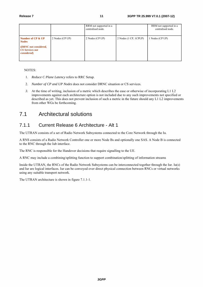
RRM not supported in a centralised node.
RRM not supported in a centralised node.
Number of CP & UP Nodes
(DRNC not considered, CS Services not considered)
2 Nodes (CP UP) 2 Nodes (CP UP) 2 Nodes (1 CP, 1CPUP) 1 Nodes (CP UP)
NOTES:
1. Reduce C Plane Latency refers to RRC Setup.
2. Number of CP and UP Nodes does not consider DRNC situation or CS services.
3. At the time of writing, inclusion of a metric which describes the ease or otherwise of incorporating L1 L2 improvements against each architecture option is not included due to any such improvements not specified or described as yet. This does not prevent inclusion of such a metric in the future should any L1 L2 improvements from other WGs be forthcoming.
7.1 Architectural solutions
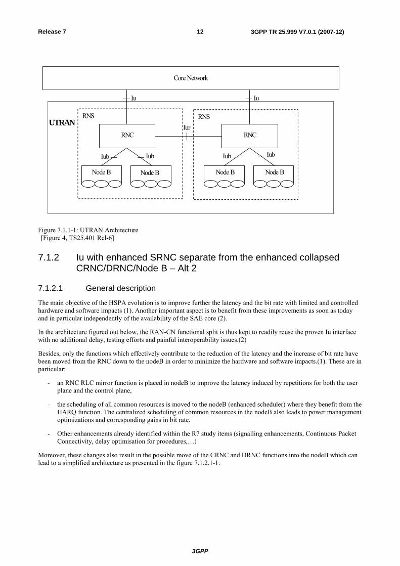
7.1.1 Current Release 6 Architecture - Alt 1 The UTRAN consists of a set of Radio Network Subsystems connected to the Core Network through the Iu.
A RNS consists of a Radio Network Controller one or more Node Bs and optionally one SAS. A Node B is connected to the RNC through the Iub interface.
The RNC is responsible for the Handover decisions that require signalling to the UE.
A RNC may include a combining/splitting function to support combination/splitting of information streams
Inside the UTRAN, the RNCs of the Radio Network Subsystems can be interconnected together through the Iur. Iu(s) and Iur are logical interfaces. Iur can be conveyed over direct physical connection between RNCs or virtual networks using any suitable transport network.
The UTRAN architecture is shown in figure 7.1.1-1.
3GPP
3GPP TR 25.999 V7.0.1 (2007-12)12Release 7
RNS
RNC
RNS
RNC
Core Network
Node B Node B Node B Node B
Iu Iu
Iur
Iub IubIub Iub
UTRAN
Figure 7.1.1-1: UTRAN Architecture [Figure 4, TS25.401 Rel-6]
7.1.2 Iu with enhanced SRNC separate from the enhanced collapsed CRNC/DRNC/Node B – Alt 2
7.1.2.1 General description
The main objective of the HSPA evolution is to improve further the latency and the bit rate with limited and controlled hardware and software impacts (1). Another important aspect is to benefit from these improvements as soon as today and in particular independently of the availability of the SAE core (2).
In the architecture figured out below, the RAN-CN functional split is thus kept to readily reuse the proven Iu interface with no additional delay, testing efforts and painful interoperability issues.(2)
Besides, only the functions which effectively contribute to the reduction of the latency and the increase of bit rate have been moved from the RNC down to the nodeB in order to minimize the hardware and software impacts.(1). These are in particular:
- an RNC RLC mirror function is placed in nodeB to improve the latency induced by repetitions for both the user plane and the control plane,
- the scheduling of all common resources is moved to the nodeB (enhanced scheduler) where they benefit from the HARQ function. The centralized scheduling of common resources in the nodeB also leads to power management optimizations and corresponding gains in bit rate.
- Other enhancements already identified within the R7 study items (signalling enhancements, Continuous Packet Connectivity, delay optimisation for procedures,…)
Moreover, these changes also result in the possible move of the CRNC and DRNC functions into the nodeB which can lead to a simplified architecture as presented in the figure 7.1.2.1-1.
3GPP
3GPP TR 25.999 V7.0.1 (2007-12)13Release 7
UTRAN (HSPA access)
SRNC
Node_B/CRNC/DRNC
Iu-PS SGSN CN
GGSN
Iu-CS
MSC
Node_B/CRNC/DRNC
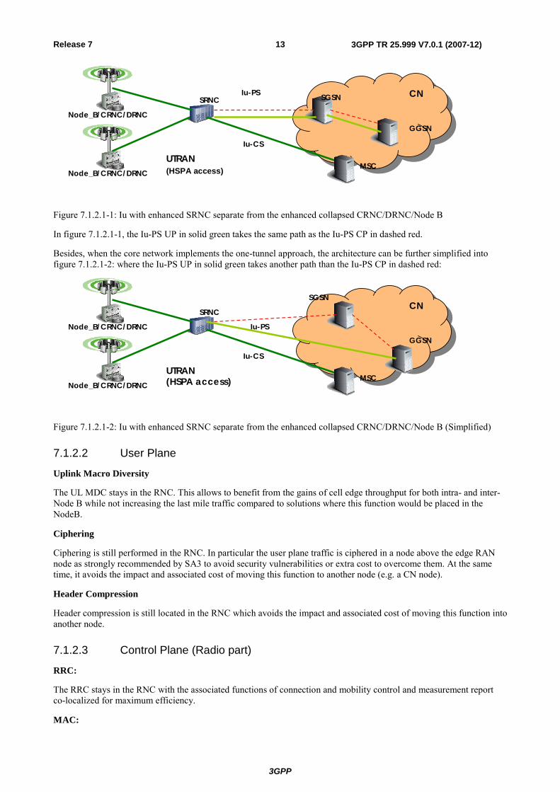
Figure 7.1.2.1-1: Iu with enhanced SRNC separate from the enhanced collapsed CRNC/DRNC/Node B
In figure 7.1.2.1-1, the Iu-PS UP in solid green takes the same path as the Iu-PS CP in dashed red.
Besides, when the core network implements the one-tunnel approach, the architecture can be further simplified into figure 7.1.2.1-2: where the Iu-PS UP in solid green takes another path than the Iu-PS CP in dashed red:
UTRAN (HSPA access)
SRNC
Node_B/CRNC/DRNC
SGSNCN
GGSN
Iu-CS
MSC
Node_B/CRNC/DRNC Iu-PS
Figure 7.1.2.1-2: Iu with enhanced SRNC separate from the enhanced collapsed CRNC/DRNC/Node B (Simplified)
7.1.2.2 User Plane
Uplink Macro Diversity
The UL MDC stays in the RNC. This allows to benefit from the gains of cell edge throughput for both intra- and inter- Node B while not increasing the last mile traffic compared to solutions where this function would be placed in the NodeB.
Ciphering
Ciphering is still performed in the RNC. In particular the user plane traffic is ciphered in a node above the edge RAN node as strongly recommended by SA3 to avoid security vulnerabilities or extra cost to overcome them. At the same time, it avoids the impact and associated cost of moving this function to another node (e.g. a CN node).
Header Compression
Header compression is still located in the RNC which avoids the impact and associated cost of moving this function into another node.
7.1.2.3 Control Plane (Radio part)
RRC:
The RRC stays in the RNC with the associated functions of connection and mobility control and measurement report co-localized for maximum efficiency.
MAC:
3GPP
3GPP TR 25.999 V7.0.1 (2007-12)14Release 7
Only dedicated channels remain scheduled in the RNC. Common channels scheduling is done in the NodeB in order to get the same latency benefit as obtained for HSDPA due to HARQ repetitions. Moreover, their centralized management will result in gains in terms of power and bit rate due to possible scheduler optimisations/anticipations.
RLC:
The RLC remains in the RNC as an anchor point for the mobility. This avoids the frequent context transfers during inter-nodeB relocations and their associated delay.
A second mirror RLC is used in the nodeB which can also further improve the latency of signalling messages.
7.1.2.4 Control Plane (Interface part)
By keeping the RNC this architecture minimizes the impact on UTRAN interfaces compared to others: it is foreseen no RANAP change on Iu, limited changes on NBAP, RNSAP (due to move of some functions). Some simplifications can also be expected due to the collapsed CRNC/DRNC/NodeB.
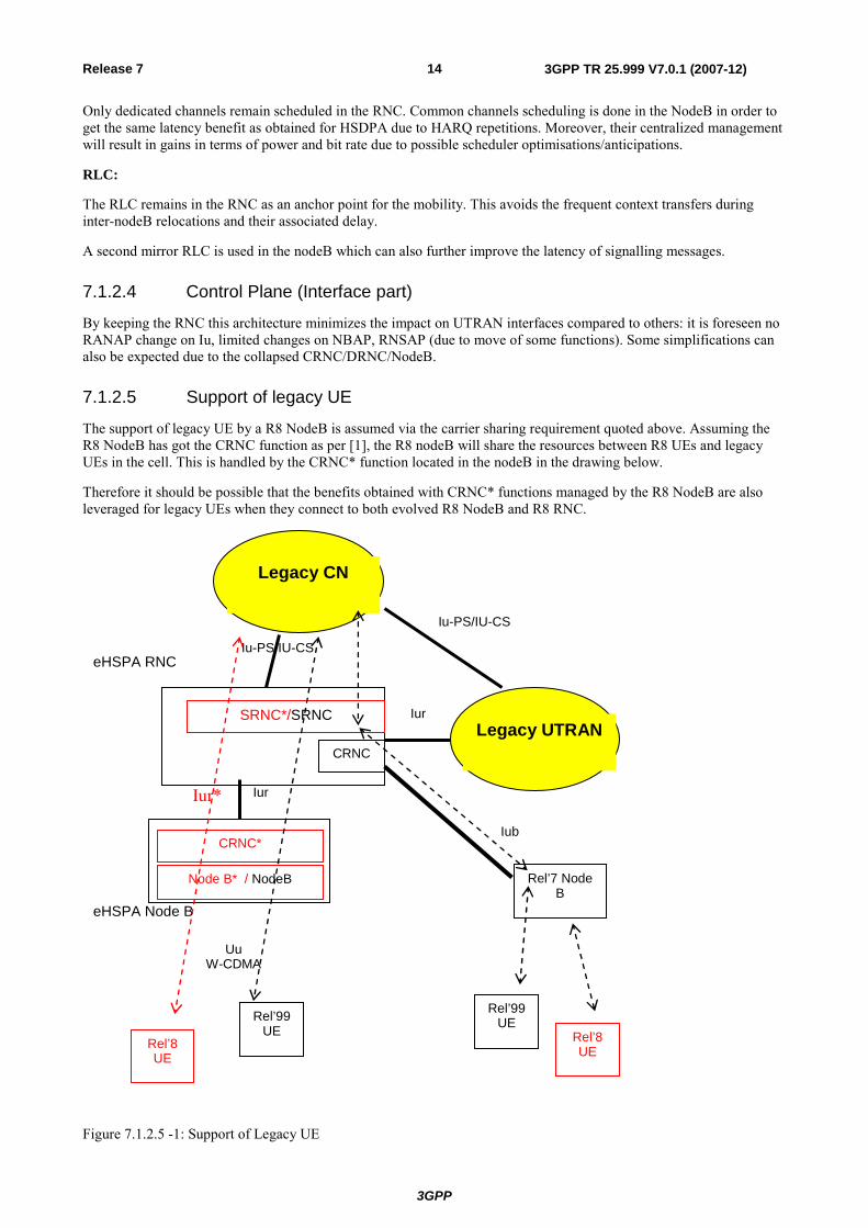
7.1.2.5 Support of legacy UE
The support of legacy UE by a R8 NodeB is assumed via the carrier sharing requirement quoted above. Assuming the R8 NodeB has got the CRNC function as per [1], the R8 nodeB will share the resources between R8 UEs and legacy UEs in the cell. This is handled by the CRNC* function located in the nodeB in the drawing below.
Therefore it should be possible that the benefits obtained with CRNC* functions managed by the R8 NodeB are also leveraged for legacy UEs when they connect to both evolved R8 NodeB and R8 RNC.
Rel’8 UE
Rel’99 UE
Node B* / NodeB
eHSPA Node B
CRNC*
SRNC*/SRNC
Uu W-CDMA
Iu-PS/IU-CS
Rel’7 Node B
Rel’99 UE
Iub
Rel’8 UE
Legacy UTRAN
Legacy CN
eHSPA RNC
Iur
Iur
Iu-PS/IU-CS
CRNC
Iur*
Figure 7.1.2.5 -1: Support of Legacy UE
3GPP
3GPP TR 25.999 V7.0.1 (2007-12)15Release 7
For backwards compatibility reasons, the RNC R8 also handles the legacy UE as follows:
The R8 RNC is a RNC* i.e. it has the RNC function of R6 with enhancements. These enhancements are optional features which may not apply to legacy UE at call set up. Therefore, when a legacy UE connects to the R8 RNC via a R8 NodeB, the R8 RNC can behave as R6 SRNC and the interface between the R8 NodeB and the R8 RNC for this legacy UE is Iur-like in this case.
Conversely, if the legacy UE connects to the R8 RNC via a legacy R6 NodeB, the R8 RNC will behave as a full R6 RNC i.e. R6 SRNC and R6 CRNC. This interface between the R8 RNC and the R6 NodeB is then a usual Iub. This scenario is further detailed in the next section.
Iu interface
The legacy UEs are then connected to the legacy network via Iu-PS or Iu-CS interface depending on the nature of the call, since these interfaces are basically supported by the solution
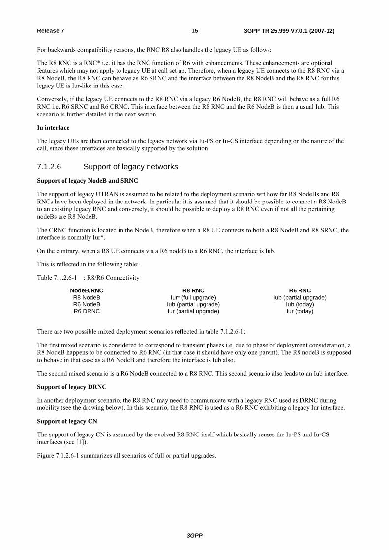
7.1.2.6 Support of legacy networks
Support of legacy NodeB and SRNC
The support of legacy UTRAN is assumed to be related to the deployment scenario wrt how far R8 NodeBs and R8 RNCs have been deployed in the network. In particular it is assumed that it should be possible to connect a R8 NodeB to an existing legacy RNC and conversely, it should be possible to deploy a R8 RNC even if not all the pertaining nodeBs are R8 NodeB.
The CRNC function is located in the NodeB, therefore when a R8 UE connects to both a R8 NodeB and R8 SRNC, the interface is normally Iur*.
On the contrary, when a R8 UE connects via a R6 nodeB to a R6 RNC, the interface is Iub.
This is reflected in the following table:
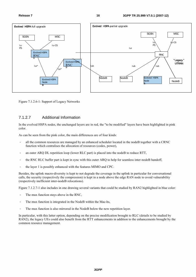
Table 7.1.2.6-1 : R8/R6 Connectivity
NodeB/RNC R8 RNC R6 RNC R8 NodeB Iur* (full upgrade) Iub (partial upgrade) R6 NodeB Iub (partial upgrade) Iub (today) R6 DRNC Iur (partial upgrade) Iur (today)
There are two possible mixed deployment scenarios reflected in table 7.1.2.6-1:
The first mixed scenario is considered to correspond to transient phases i.e. due to phase of deployment consideration, a R8 NodeB happens to be connected to R6 RNC (in that case it should have only one parent). The R8 nodeB is supposed to behave in that case as a R6 NodeB and therefore the interface is Iub also.
The second mixed scenario is a R6 NodeB connected to a R8 RNC. This second scenario also leads to an Iub interface.
Support of legacy DRNC
In another deployment scenario, the R8 RNC may need to communicate with a legacy RNC used as DRNC during mobility (see the drawing below). In this scenario, the R8 RNC is used as a R6 RNC exhibiting a legacy Iur interface.
Support of legacy CN
The support of legacy CN is assumed by the evolved R8 RNC itself which basically reuses the Iu-PS and Iu-CS interfaces (see [1]).
Figure 7.1.2.6-1 summarizes all scenarios of full or partial upgrades.
3GPP
3GPP TR 25.999 V7.0.1 (2007-12)16Release 7
Figure 7.1.2.6-1: Support of Legacy Networks
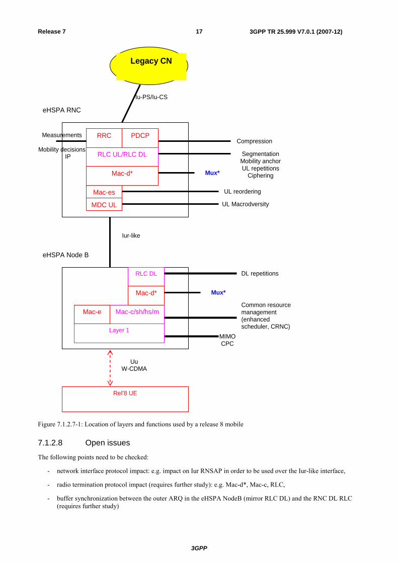
7.1.2.7 Additional Information
In the evolved HSPA nodes, the unchanged layers are in red, the "to be modified" layers have been highlighted in pink color.
As can be seen from the pink color, the main differences are of four kinds:
- all the common resources are managed by an enhanced scheduler located in the nodeB together with a CRNC function which centralises the allocation of resources (codes, power),
- an outer ARQ DL repetition loop (lower RLC part) is placed into the nodeB to reduce RTT,
- the RNC RLC buffer part is kept in sync with this outer ARQ to help for seamless inter-nodeB handoff,
- the layer 1 is possibly enhanced with the features MIMO and CPC.
Besides, the uplink macro-diversity is kept to not degrade the coverage in the uplink in particular for conversational calls, the security (respectively the compression) is kept in a node above the edge RAN node to avoid vulnerability (respectively inefficient inter-nodeB relocations).
Figure 7.1.2.7-1 also includes in one drawing several variants that could be studied by RAN2 highlighted in blue color:
- The mux function stays above in the RNC,
- The mux function is integrated in the NodeB within the Mac-hs,
- The mux function is also mirrored in the NodeB below the new repetition layer.
In particular, with this latter option, depending on the precise modification brought to RLC (details to be studied by RAN2), the legacy UEs could also benefit from the RTT enhancements in addition to the enhancements brought by the common resource management.
MSC
Evolved
RNC
NodeB
”Legacy ”UTRAN
Iu-CS
Evolved HSPA - - Evolved HSPA -
Evolved HSPA NodeB
Evolved HSPA NodeB
SGSN
Iur*
Evolved HSPA NodeB
SGSN MSC
RNC
NodeBNodeB
”Legacy ”UTRAN
Iu-PS
Evolved HSPA full upgrade - - Evolved HSPA partial upgrade-
Evolved HSPA NodeB
Evolved HSPA RNC
Iur*
Iu-PS
Iu-CS
Iub Iub
Evolved HSPA NodeB
Evolved HSPA RNC
NodeB
Iub
Iur
3GPP
3GPP TR 25.999 V7.0.1 (2007-12)17Release 7
RLC DL
eHSPA Node B
RLC UL/RLC DL
MIMO CPC
Segmentation Mobility anchor UL repetitions
Ciphering
Rel’8 UE
Common resource management (enhanced scheduler, CRNC)
Legacy CN
eHSPA RNC
Compression
Iur-like
Iu-PS/Iu-CS
MDC UL
Mac-d*
Layer 1
RRC PDCP
Mac-es
Mac-c/sh/hs/m Mac-e
DL repetitions
Measurements
Mobility decisions IP
Uu W-CDMA
UL Macrodversity
UL reordering
Mac-d* Mux*
Mux*
Figure 7.1.2.7-1: Location of layers and functions used by a release 8 mobile
7.1.2.8 Open issues
The following points need to be checked:
- network interface protocol impact: e.g. impact on Iur RNSAP in order to be used over the Iur-like interface,
- radio termination protocol impact (requires further study): e.g. Mac-d*, Mac-c, RLC,
- buffer synchronization between the outer ARQ in the eHSPA NodeB (mirror RLC DL) and the RNC DL RLC (requires further study)
3GPP
3GPP TR 25.999 V7.0.1 (2007-12)18Release 7
7.1.3 PS User Plane /Control Plane split, CP functions in RNC, direct UP tunnel PS CN – Node B – Alt 3
7.1.3.1 General description
The current UTRAN architecture, inherited from GPRS, is not optimised for very pervasive broadband packet services. In fact in this architecture the presence of an RNC in the User Plane path plays as a bottleneck for the traffic throughput. This is due to two different but linked factors:
- limitations given by switching and routing capacity of an RNC.
- limitations given by RLC/MAC and Iub Framing Protocol termination in the RNC.
A possible solution to those limitations is allowing User Plane and Control Plane to scale separately and terminating the User Plane protocols in the Node Bs. That is introducing a 'flat' architecture for the UP part.
As a consequence, the Node B will have a direct IP broadband connection to the Packet Core.
Moreover latency and delay on the user plane will improve since radio protocols and retransmission will be terminated in the Node B, similar to what has been decided for LTE.
At the same time, other important aspects such as mobility, efficient coordination between different layer (pico/micro/macro coverage), reuse of legacy investments should not be overlooked. This can be achieved by reusing the RNC functions for the Control Plane.
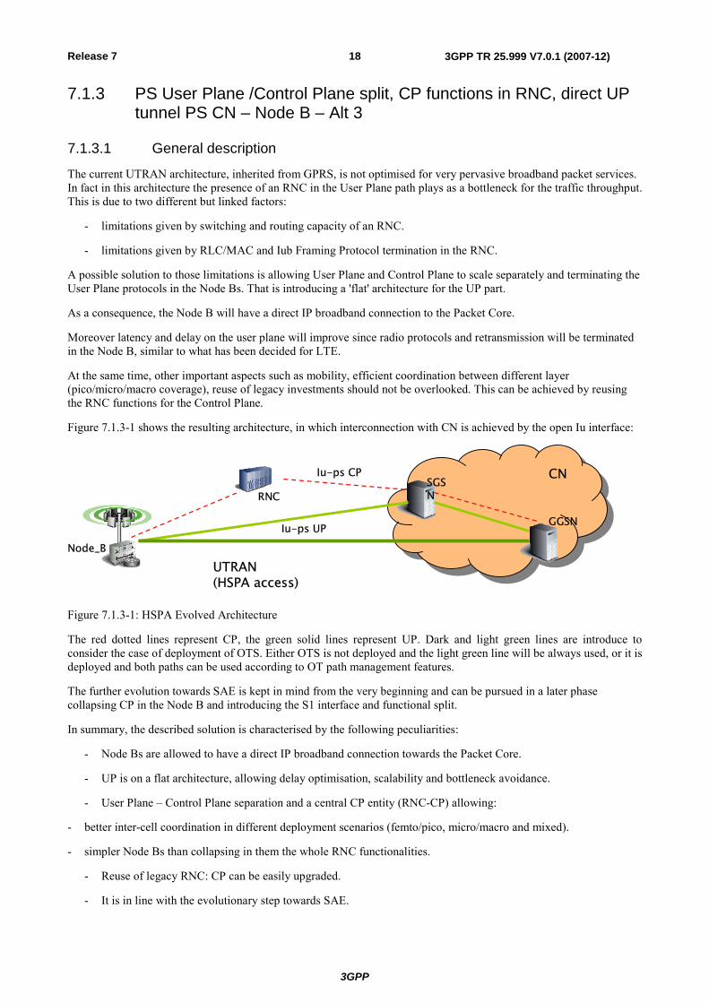
Figure 7.1.3-1 shows the resulting architecture, in which interconnection with CN is achieved by the open Iu interface:
UTRAN (HSPA access)
RNC
Node_B
Iu-ps CPSGSN
CN
GGSNIu-ps UP
Figure 7.1.3-1: HSPA Evolved Architecture
The red dotted lines represent CP, the green solid lines represent UP. Dark and light green lines are introduce to consider the case of deployment of OTS. Either OTS is not deployed and the light green line will be always used, or it is deployed and both paths can be used according to OT path management features.
The further evolution towards SAE is kept in mind from the very beginning and can be pursued in a later phase collapsing CP in the Node B and introducing the S1 interface and functional split.
In summary, the described solution is characterised by the following peculiarities:
- Node Bs are allowed to have a direct IP broadband connection towards the Packet Core.
- UP is on a flat architecture, allowing delay optimisation, scalability and bottleneck avoidance.
- User Plane – Control Plane separation and a central CP entity (RNC-CP) allowing:
- better inter-cell coordination in different deployment scenarios (femto/pico, micro/macro and mixed).
- simpler Node Bs than collapsing in them the whole RNC functionalities.
- Reuse of legacy RNC: CP can be easily upgraded.
- It is in line with the evolutionary step towards SAE.
3GPP
3GPP TR 25.999 V7.0.1 (2007-12)19Release 7
7.1.3.2 Protocol architecture
User plane
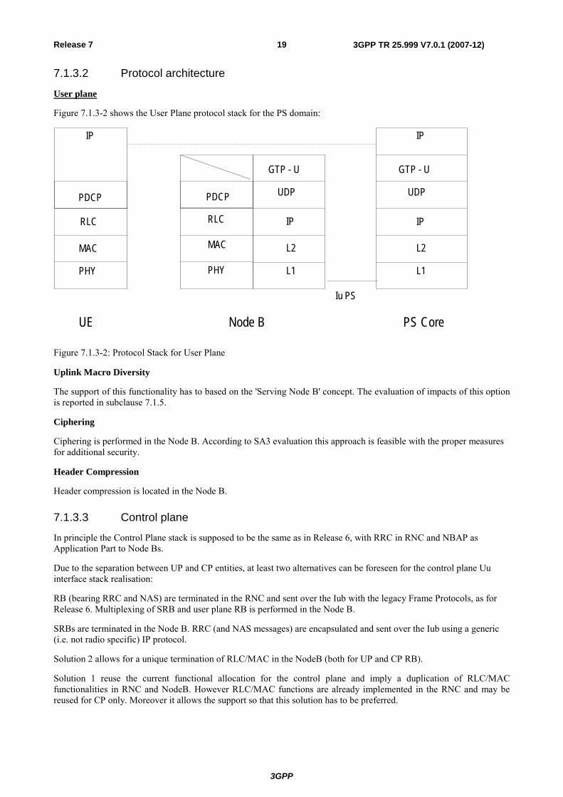
Figure 7.1.3-2 shows the User Plane protocol stack for the PS domain:
IP
GTP - U
UDP
IP
L2
L1
GTP - U
UDP
IP
L2
L1
RLC
PHY
MAC
RLC
PHY
MAC
IP
UE Node B PS Core
Iu PS
PDCP PDCP
Figure 7.1.3-2: Protocol Stack for User Plane
Uplink Macro Diversity
The support of this functionality has to based on the 'Serving Node B' concept. The evaluation of impacts of this option is reported in subclause 7.1.5.
Ciphering
Ciphering is performed in the Node B. According to SA3 evaluation this approach is feasible with the proper measures for additional security.
Header Compression
Header compression is located in the Node B.
7.1.3.3 Control plane
In principle the Control Plane stack is supposed to be the same as in Release 6, with RRC in RNC and NBAP as Application Part to Node Bs.
Due to the separation between UP and CP entities, at least two alternatives can be foreseen for the control plane Uu interface stack realisation:
RB (bearing RRC and NAS) are terminated in the RNC and sent over the Iub with the legacy Frame Protocols, as for Release 6. Multiplexing of SRB and user plane RB is performed in the Node B.
SRBs are terminated in the Node B. RRC (and NAS messages) are encapsulated and sent over the Iub using a generic (i.e. not radio specific) IP protocol.
Solution 2 allows for a unique termination of RLC/MAC in the NodeB (both for UP and CP RB).
Solution 1 reuse the current functional allocation for the control plane and imply a duplication of RLC/MAC functionalities in RNC and NodeB. However RLC/MAC functions are already implemented in the RNC and may be reused for CP only. Moreover it allows the support so that this solution has to be preferred.
3GPP
3GPP TR 25.999 V7.0.1 (2007-12)20Release 7
7.1.3.4 Support of legacy UEs
No or minimum impacts are foreseen on terminals. The same protocol stack can be used.
7.1.3.5 Interworking with legacy architecture
Interworking with legacy architecture is provided at RNC level.
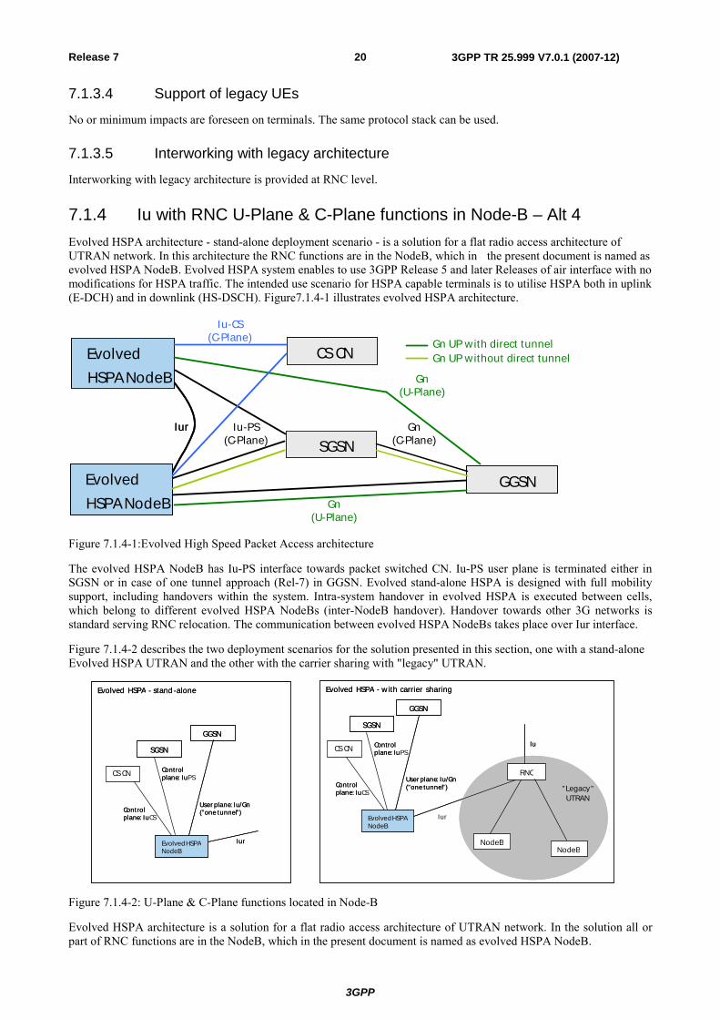
7.1.4 Iu with RNC U-Plane & C-Plane functions in Node-B – Alt 4 Evolved HSPA architecture - stand-alone deployment scenario - is a solution for a flat radio access architecture of UTRAN network. In this architecture the RNC functions are in the NodeB, which in the present document is named as evolved HSPA NodeB. Evolved HSPA system enables to use 3GPP Release 5 and later Releases of air interface with no modifications for HSPA traffic. The intended use scenario for HSPA capable terminals is to utilise HSPA both in uplink (E-DCH) and in downlink (HS-DSCH). Figure7.1.4-1 illustrates evolved HSPA architecture.
SGSN
GGSN
EvolvedHSPA NodeB
EvolvedHSPA NodeB
Iur
SGSN
GGSN
EvolvedHSPA NodeB
EvolvedHSPA NodeB
Iur
Gn UP with direct tunnelGn UP without direct tunnel
Gn(U-Plane)
Gn(C-Plane)
Iu-PS(C-Plane)
Gn(U-Plane)
SGSNCS CN
Iu-CS(C-Plane)
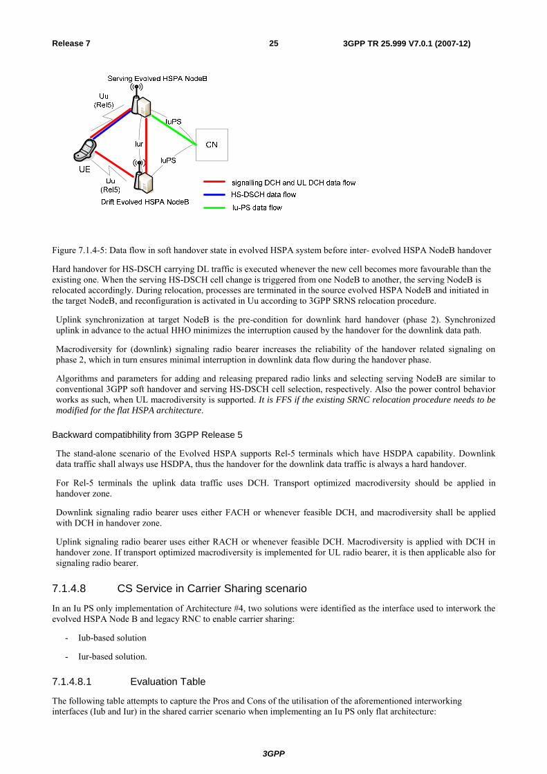
Figure 7.1.4-1:Evolved High Speed Packet Access architecture
The evolved HSPA NodeB has Iu-PS interface towards packet switched CN. Iu-PS user plane is terminated either in SGSN or in case of one tunnel approach (Rel-7) in GGSN. Evolved stand-alone HSPA is designed with full mobility support, including handovers within the system. Intra-system handover in evolved HSPA is executed between cells, which belong to different evolved HSPA NodeBs (inter-NodeB handover). Handover towards other 3G networks is standard serving RNC relocation. The communication between evolved HSPA NodeBs takes place over Iur interface.
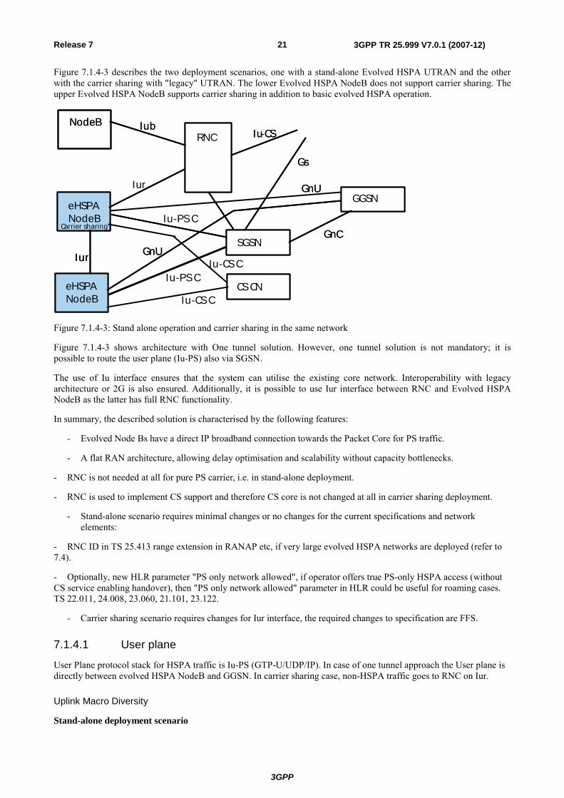
Figure 7.1.4-2 describes the two deployment scenarios for the solution presented in this section, one with a stand-alone Evolved HSPA UTRAN and the other with the carrier sharing with "legacy" UTRAN.
Evolved HSPA NodeB
GGSN
User plane : Iu / Gn( ” one tunnel” ) Control
plane : Iu
Iur
EvolvedHSPA NodeB
GGSN
User plane: Iu/Gn(”one tunnel”)
RNC
NodeBNodeB
”Legacy”UTRAN
Iu
Evolved HSPA - stand -alone Evolved HSPA - w ith carrier sharing
Evolved HSPA NodeB
GGSN
User plane : Iu / Gn( ” one tunnel” ) Control
plane : IuCS
Iur
EvolvedHSPA NodeB
GGSN
User plane: Iu/Gn(”one tunnel”)
Iur
RNC
NodeBNodeB
”Legacy”UTRAN
Iu
Evolved HSPA - stand -alone Evolved HSPA - w ith carrier sharing
SGSNSGSN
Control plane : Iu Control plane : IuPS CS CN
Controlplane: IuControlplane: IuCS
SGSNSGSN
Controlplane: IuControlplane: IuPSCS CN
Figure 7.1.4-2: U-Plane & C-Plane functions located in Node-B
Evolved HSPA architecture is a solution for a flat radio access architecture of UTRAN network. In the solution all or part of RNC functions are in the NodeB, which in the present document is named as evolved HSPA NodeB.
3GPP
3GPP TR 25.999 V7.0.1 (2007-12)21Release 7
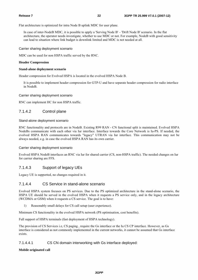
Figure 7.1.4-3 describes the two deployment scenarios, one with a stand-alone Evolved HSPA UTRAN and the other with the carrier sharing with "legacy" UTRAN. The lower Evolved HSPA NodeB does not support carrier sharing. The upper Evolved HSPA NodeB supports carrier sharing in addition to basic evolved HSPA operation.
SGSN
GGSN
RNC
eHSPA NodeB
eHSPA NodeB
NodeB Iub
Iur
Iu - CS
Gn U
Gn U Gn C
Gs
Iur
Carrier sharing SGSN
GGSN
RNC
eHSPA NodeB
eHSPA NodeB
NodeB Iub Iu - CS
Gn U
Gn U Gn C
Gs
Iur
Carrier sharing
SGSN CS CN
Iu-CS C
Iu-CS C
Iu-PS C
Iu-PS C
Figure 7.1.4-3: Stand alone operation and carrier sharing in the same network
Figure 7.1.4-3 shows architecture with One tunnel solution. However, one tunnel solution is not mandatory; it is possible to route the user plane (Iu-PS) also via SGSN.
The use of Iu interface ensures that the system can utilise the existing core network. Interoperability with legacy architecture or 2G is also ensured. Additionally, it is possible to use Iur interface between RNC and Evolved HSPA NodeB as the latter has full RNC functionality.
In summary, the described solution is characterised by the following features:
- Evolved Node Bs have a direct IP broadband connection towards the Packet Core for PS traffic.
- A flat RAN architecture, allowing delay optimisation and scalability without capacity bottlenecks.
- RNC is not needed at all for pure PS carrier, i.e. in stand-alone deployment.
- RNC is used to implement CS support and therefore CS core is not changed at all in carrier sharing deployment.
- Stand-alone scenario requires minimal changes or no changes for the current specifications and network elements:
- RNC ID in TS 25.413 range extension in RANAP etc, if very large evolved HSPA networks are deployed (refer to 7.4).
- Optionally, new HLR parameter "PS only network allowed", if operator offers true PS-only HSPA access (without CS service enabling handover), then "PS only network allowed" parameter in HLR could be useful for roaming cases. TS 22.011, 24.008, 23.060, 21.101, 23.122.
- Carrier sharing scenario requires changes for Iur interface, the required changes to specification are FFS.
7.1.4.1 User plane
User Plane protocol stack for HSPA traffic is Iu-PS (GTP-U/UDP/IP). In case of one tunnel approach the User plane is directly between evolved HSPA NodeB and GGSN. In carrier sharing case, non-HSPA traffic goes to RNC on Iur.
Uplink Macro Diversity
Stand-alone deployment scenario
3GPP
3GPP TR 25.999 V7.0.1 (2007-12)22Release 7
Flat architecture is optimized for intra Node B uplink MDC for user plane.
In case of inter-NodeB MDC, it is possible to apply a 'Serving Node B' – 'Drift Node B' scenario. In the flat architecture, the operator needs investigate, whether to use MDC or not. For example, NodeB with good sensitivity can lead to situation where link budget is downlink limited and MDC is not needed at all.
Carrier sharing deployment scenario
MDC can be used for non HSPA traffic served by the RNC.
Header Compression
Stand-alone deployment scenario
Header compression for Evolved HSPA is located in the evolved HSPA Node B.
It is possible to implement header compression for GTP-U and have separate header compression for radio interface in NodeB.
Carrier sharing deployment scenario
RNC can implement HC for non HSPA traffic.
7.1.4.2 Control plane
Stand-alone deployment scenario
RNC functionality and protocols are in NodeB. Existing R99 RAN - CN functional split is maintained. Evolved HSPA NodeBs communicate with each other via Iur interface. Interface towards the Core Network is Iu-PS. If needed, the evolved HSPA RAN communicates towards "legacy" UTRAN via Iur interface. This communication may not be always needed, e.g. in case the evolved HSPA RAN has its own carrier.
Carrier sharing deployment scenario
Evolved HSPA NodeB interfaces an RNC via Iur for shared carrier (CS, non-HSPA traffic). The needed changes on Iur for carrier sharing are FFS.
7.1.4.3 Support of legacy UEs
Legacy UE is supported, no changes required in it.
7.1.4.4 CS Service in stand-alone scenario
Evolved HSPA system focuses on PS services. Due to the PS optimized architecture in the stand-alone scenario, the HSPA UE should be served in the evolved HSPA when it requests a PS service only, and in the legacy architecture (WCDMA or GSM) when it requests a CS service. The goal is to have:
1) Reasonably small delays for CS call setup (user experience).
Minimum CS functionality in the evolved HSPA network (PS optimisation, cost benefits).
Full support of HSPA terminals (fast deployment of HSPA technology).
The provision of CS Services i.e, CS paging , require the Gs interface or the Iu CS CP interface. However, as Gs interface is considered as not commonly implemented in the current networks, it cannot be assumed that Gs interface exists.
7.1.4.4.1 CS CN domain interworking with Gs interface deployed:
Mobile originated call
3GPP
3GPP TR 25.999 V7.0.1 (2007-12)23Release 7
- RNC functionality in NodeB triggers Intersystem (to 2G) or inter frequency HO towards legacy network architecture with full CS support in the call establishment. Details of the procedure FFS.
- UE uses legacy network architecture for CS and CS+PS traffic.
Mobile terminated CS call
- SGSN connects to MSC/VLR via Gs interface.
- VLR can initiate CS call via Gs interface.
- RNC functionality in NodeB triggers Intersystem (to 2G) or inter frequency HO towards legacy network architecture with full CS support in the call establishment. Details of the procedure FFS.
Due to the CS call setup delay, without further optimization of the current relocation procedure, this solution is not applicable.
7.1.4.4.2 CS CN domain interworking without deployed Gs interface:
Mobile originated call
PS only RAN triggers Intersystem (to 2G) or inter frequency HO towards legacy network architecture with full CS support in the call establishment.
UE uses legacy network architecture for CS and CS+PS traffic
Mobile terminated CS call
PS only RAN connects to MSC/VLR via Iu-cs signalling interface, hence MSC/VLR is able to trigger cs paging, continuation like for Mobile originated call.
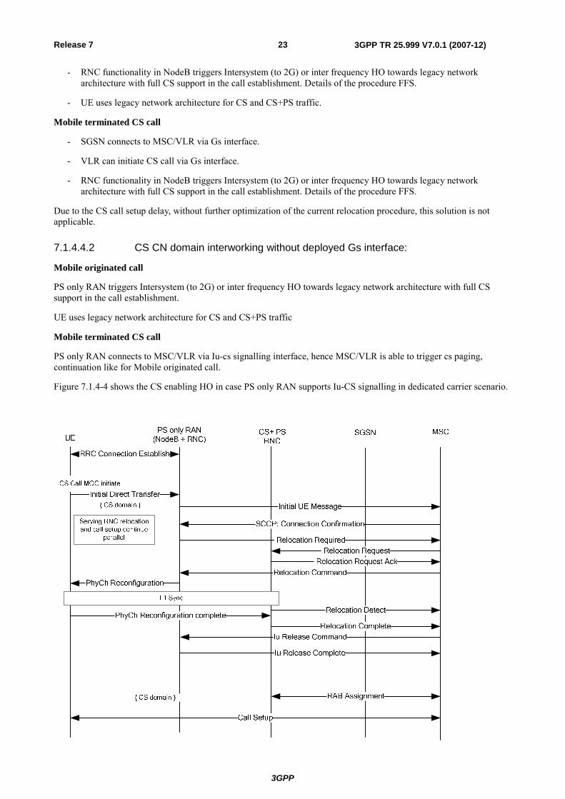
Figure 7.1.4-4 shows the CS enabling HO in case PS only RAN supports Iu-CS signalling in dedicated carrier scenario.
3GPP
3GPP TR 25.999 V7.0.1 (2007-12)24Release 7
Figure 7.1.4-4:CS service enabling HO with Iu-CS signalling support
RNC functionality notices from RRC: Initial Direct transfer that the UE is starting a CS call, which triggers the setup of a signalling connection towards the CS CN domain, conveying the RANAP: Initial_UE message). MSC acknowledges SCCP connection by sending the Connection Confirmation SCCP message. From MSC point of view Relocation can be started right after it confirmed the Iu-cs signalling connection setup. The call setup signalling proceeds in parallel with the Relocation procedure (NOTE: whole L3 message sequence is not shown in figure 7.1.4-4 for readability reasons, e.g. AUTHENTICATION messages are not shown). During the relocation preparation phase, MSC can exchange the call setup messages with UE in parallel or buffer the call setup messages. So before Relocation command call setup communication to UE goes through source RNC and after Relocation complete through target RNC.
Mobile terminated calls can be handled in similar way: Serving RNC relocation procedure can be started at the same time (after Connection Confirmation message).
Based on the study above, it can be concluded that the interworking of this architecture with CS domain can be achieved only if CS signalling connection is available unless further optimization is performed in the Gs-deployed case for the relocation procedure.
7.1.4.5 Interworking with legacy architecture
Interworking with legacy architecture is provided on RNC level, either via Iur or via Iu
Stand-alone deployment scenario
It is possible to use Iur or use only Hard Handover, so legacy RNC does not need to support high number of Iur interfaces
7.1.4.6 Paging
In Cell_PCH state paging can be constrained to only one cell. Serving Evolved HSPA NodeB can find UE with paging. In Cell_PCH serving Evolved NodeB acts like SRNC towards core network. If UE is in a cell under other Evolved HSPA Node B, then the serving Evolved HSPA Node B must send RNSAP paging towards the other Evolved HSPA Node B.
In URA_PCH state, serving Evolved NodeB acts like SRNC towards the core network. If there are more than one Evolved HSPA NodeBs in the URA, then serving Evolved HSPA NodeB must send RNSAP paging towards other Evolved HSPA NodeB.
7.1.4.7 Soft Handover for Signalling Radio Bearers:
As the physical control channel (DPCCH) is maintained in the cells within the active set, as is in macrodiversity case in general (recall the use of uplink combining being transparent to the UE), the uplink and downlink L1 synchronization is existing and the actual (hard) handover can be made fast for user plane data. If desired, for SRB the actual macrodiversity combining can be applied (UL, DL or both direction, recall that in Release 5 SRB has to be mapped on DCH both in uplink and downlink) as the resulting transport overhead is only marginal. To enable MDC for SRB, not only the Iur control plane but also the user plane remains between the evolved HSPA NodeBs. Once the full Iur is supported between the evolved HSPA NodeBs, it is possible to use it also for anchoring of the Serving NodeB functionality.
Benefits of soft handover usage in inter-NodeB handover
From radio interface (UE) point of view intra-system evolved HSPA handover is a standard 3GPP HSPA handover.
Evolved HSPA specific changes are mostly due to serving evolved HSPA NodeB relocation. The specific use of macrodiversity relates to soft handover state. In case of evolved HSPA, the inter-NodeB handover proceeds in 2 phases:
1) New radio links may be added at least for signaling radio bearers (DCH) and also for uplink user plane bearers (UL DCH) to operate in soft handover mode. They provide more reliable signaling over DCH, in-advance uplink synchronization on the target HSPA NodeB (Drift) and macrodiversity gain in uplink. Control and macro diversity combining point stays still in the source HSPA NodeB (Serving).
3GPP
3GPP TR 25.999 V7.0.1 (2007-12)25Release 7
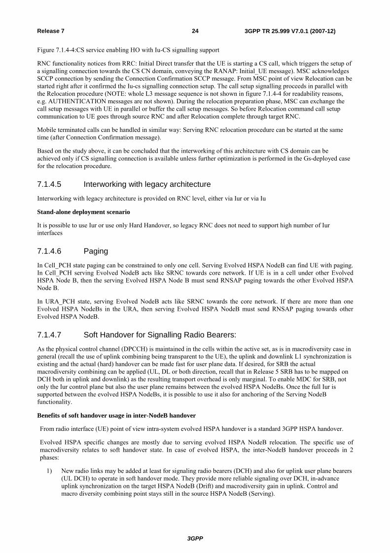
Figure 7.1.4-5: Data flow in soft handover state in evolved HSPA system before inter- evolved HSPA NodeB handover
Hard handover for HS-DSCH carrying DL traffic is executed whenever the new cell becomes more favourable than the existing one. When the serving HS-DSCH cell change is triggered from one NodeB to another, the serving NodeB is relocated accordingly. During relocation, processes are terminated in the source evolved HSPA NodeB and initiated in the target NodeB, and reconfiguration is activated in Uu according to 3GPP SRNS relocation procedure.
Uplink synchronization at target NodeB is the pre-condition for downlink hard handover (phase 2). Synchronized uplink in advance to the actual HHO minimizes the interruption caused by the handover for the downlink data path.
Macrodiversity for (downlink) signaling radio bearer increases the reliability of the handover related signaling on phase 2, which in turn ensures minimal interruption in downlink data flow during the handover phase.
Algorithms and parameters for adding and releasing prepared radio links and selecting serving NodeB are similar to conventional 3GPP soft handover and serving HS-DSCH cell selection, respectively. Also the power control behavior works as such, when UL macrodiversity is supported. It is FFS if the existing SRNC relocation procedure needs to be modified for the flat HSPA architecture.
Backward compatibhility from 3GPP Release 5
The stand-alone scenario of the Evolved HSPA supports Rel-5 terminals which have HSDPA capability. Downlink data traffic shall always use HSDPA, thus the handover for the downlink data traffic is always a hard handover.
For Rel-5 terminals the uplink data traffic uses DCH. Transport optimized macrodiversity should be applied in handover zone.
Downlink signaling radio bearer uses either FACH or whenever feasible DCH, and macrodiversity shall be applied with DCH in handover zone.
Uplink signaling radio bearer uses either RACH or whenever feasible DCH. Macrodiversity is applied with DCH in handover zone. If transport optimized macrodiversity is implemented for UL radio bearer, it is then applicable also for signaling radio bearer.
7.1.4.8 CS Service in Carrier Sharing scenario
In an Iu PS only implementation of Architecture #4, two solutions were identified as the interface used to interwork the evolved HSPA Node B and legacy RNC to enable carrier sharing:
- Iub-based solution
- Iur-based solution.
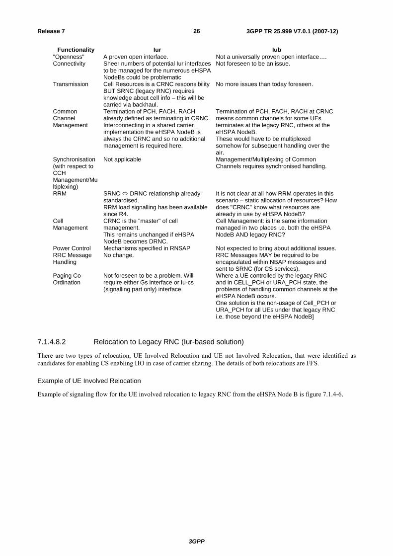
7.1.4.8.1 Evaluation Table
The following table attempts to capture the Pros and Cons of the utilisation of the aforementioned interworking interfaces (Iub and Iur) in the shared carrier scenario when implementing an Iu PS only flat architecture:
3GPP
3GPP TR 25.999 V7.0.1 (2007-12)26Release 7
Functionality Iur Iub "Openness" A proven open interface. Not a universally proven open interface…. Connectivity Sheer numbers of potential Iur interfaces
to be managed for the numerous eHSPA NodeBs could be problematic
Not foreseen to be an issue.
Transmission Cell Resources is a CRNC responsibility BUT SRNC (legacy RNC) requires knowledge about cell info – this will be carried via backhaul.
No more issues than today foreseen.
Common Channel Management
Termination of PCH, FACH, RACH already defined as terminating in CRNC. Interconnecting in a shared carrier implementation the eHSPA NodeB is always the CRNC and so no additional management is required here.
Termination of PCH, FACH, RACH at CRNC means common channels for some UEs terminates at the legacy RNC, others at the eHSPA NodeB. These would have to be multiplexed somehow for subsequent handling over the air.
Synchronisation (with respect to CCH Management/Multiplexing)
Not applicable Management/Multiplexing of Common Channels requires synchronised handling.
RRM SRNC DRNC relationship already standardised. RRM load signalling has been available since R4.
It is not clear at all how RRM operates in this scenario – static allocation of resources? How does "CRNC" know what resources are already in use by eHSPA NodeB?
Cell Management
CRNC is the "master" of cell management. This remains unchanged if eHSPA NodeB becomes DRNC.
Cell Management: is the same information managed in two places i.e. both the eHSPA NodeB AND legacy RNC?
Power Control Mechanisms specified in RNSAP Not expected to bring about additional issues.RRC Message Handling
No change. RRC Messages MAY be required to be encapsulated within NBAP messages and sent to SRNC (for CS services).
Paging Co-Ordination
Not foreseen to be a problem. Will require either Gs interface or Iu-cs (signalling part only) interface.
Where a UE controlled by the legacy RNC and in CELL_PCH or URA_PCH state, the problems of handling common channels at the eHSPA NodeB occurs. One solution is the non-usage of Cell_PCH or URA_PCH for all UEs under that legacy RNC i.e. those beyond the eHSPA NodeB]
7.1.4.8.2 Relocation to Legacy RNC (Iur-based solution)
There are two types of relocation, UE Involved Relocation and UE not Involved Relocation, that were identified as candidates for enabling CS enabling HO in case of carrier sharing. The details of both relocations are FFS.
Example of UE Involved Relocation
Example of signaling flow for the UE involved relocation to legacy RNC from the eHSPA Node B is figure 7.1.4-6.
3GPP
3GPP TR 25.999 V7.0.1 (2007-12)27Release 7
SGSNUE RNC MSC
eHSPA NB(PS RNC+NB and
CS NB+CRNC)
PhyCh Reconfigurationwith new U-RNTI etc
Initial Direct Transfer
{ CS domain }
Relocation Detect
Call Setup
CS Call MOC initiate
Relocation Required with D-RNTI
Iu Release Command
Relocation Request Ack
Relocation Command
PhyCh Reconfiguration completeby DCH or E-DCH DATA FRAME over Iur Relocation Complete
Iu Release Complete
{ CS domain }
RAB Assignment
Relocation Requestwith D-RNTI
Serving RNC relocation and call setup continue
parallel
Initial UE MessageSCCP: Connection Confirmation (RANAP Message)
RL SetupRL Setup Response
UE in Cell_DCH
Relocation Required with D-RNTI
Relocation Requestwith D-RNTI
Relocation Request Ack
Relocation Command
Relocation Detect
Relocation Complete
RL Reconfiguration
Iur
RLC ACK
L1 Synchronisation RL Restore Indication
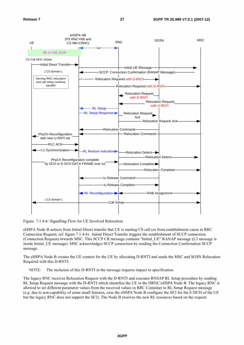
Figure 7.1.4-6: Signalling Flow for UE Involved Relocation
eHSPA Node B notices from Initial Direct transfer that UE is starting CS call (or from establishment cause in RRC Connection Request, ref. figure 7.1.4-6) . Initial Direct Transfer triggers the establishment of SCCP connection (Connection Request) towards MSC. This SCCP CR message contains "Initial_UE" RANAP message (L3 message is inside Initial_UE message). MSC acknowledges SCCP connection by sending the Connection Confirmation SCCP message.
The eHSPA Node B creates the UE context for the UE by allocating D-RNTI and sends the MSC and SGSN Relocation Required with this D-RNTI.
NOTE: The inclusion of this D-RNTI in the message requires impact to specification.
The legacy RNC receives Relocation Request with the D-RNTI and executes RNSAP RL Setup procedure by sending RL Setup Request message with the D-RNTI which identifies the UE in the DRNC/eHSPA Node B. The legacy RNC is allowed to set different parameter values from the received values in RRC Container to RL Setup Request message (e.g. due to non-capability of some small features, case the eHSPA Node B configure the SF2 for the E-DCH of the UE but the legacy RNC does not support the SF2). The Node B reserves the new RL resources based on the request.
3GPP
3GPP TR 25.999 V7.0.1 (2007-12)28Release 7
After the reception of the Relocation Command which contains RRC: Physical Channel Reconfiguration Request informs the new U-RNTI and new physical channel parameters etc to UE, the eHSPA Node B sends UE the Physical Channel Reconfiguration Request and if it does not receive Failure message from UE, the eHSPA and UE executes intra-frequency HHO (using new physical layer parameters in received RL Setup Request) when the time in the activation time is elapsed.
RNSAP RL Reconfiguration procedure for establishing Transport Channel for CS RAB over Iur is triggered after the reception of RAB Assignment Request message establishes CS RAB.
Specification Changes
There is only one change identified in the specification for enabling the relocation.
- Change the presence of d-RNTI in Source RNC to Target RNC Transport Container in RANAP: RELOCATION REQUIRED/RELOCATION REQUEST messages from conditional to optional for allowing source RNC to include the d-RNTI in case of UE involved relocation in addition to UE not involved relocation.
This change does not generate ASN.1 change since the presence of the d-RNTI has been defined in current RANAP.
Example of UE Not Involved Relocation
In UE Not Involved Relocation in current spec, the Target RNC has already had some information on physical layer parameters configured for UE, e.g. Code information for UL and DL DPCH configured for the UE so that some parameters for RL configured by Source RNC do not need to be transferred to Target RNC by RRC Container. However in the relocation enabling carrier sharing, some additional physical layer parameters need to be transferred to the target RNC(legacy RNC) since the RNC does not have any information on the parameters configured for UE and the RNC shall continue to use physical layer parameter configured by eHSPA Node B during relocation.
Example of signaling flow for the UE not involved relocation to legacy RNC from the eHSPA Node B is figure 7.1.4-7.
3GPP
3GPP TR 25.999 V7.0.1 (2007-12)29Release 7
SGSNUE RNC MSC
eHSPA NB(PS RNC+NB and
CS NB+CRNC)
Initial Direct Transfer{ CS domain }
Relocation Detect
Call Setup
CS Call MOC initiate
Relocation Required with Target Cell ID, RRC Container includes parameters values configured for
RL
Iu Release Command
Relocation Request Ack
Relocation Command
Relocation Complete
Iu Release Complete
{ CS domain }
RAB Assignment
Relocation Requestwith Target Cell ID and
RRC Container
Serving RNC relocation and call setup continue
parallel
Initial UE Message
SCCP: Connection Confirmation (RANAP Message)
RL Setup with received paramter values
RL Setup Response
UE in Cell_DCH
Relocation Commit
UTRAN Mobility Information with new U-RNTI(by DCH or HS-DSCH DATA FRAME over Iur)
UTRAN Mobility Information Confirm (by DCH or E-DCH DATA FRAME over Iur)
Relocation Required with Target Cell ID, RRC Container includes parameters values configured for RL
Relocation Requestwith Target Cell ID and RRC Container
Relocation Request Ack
Relocation Command
Relocation Detect
Relocation Complete
RL Reconfiguration
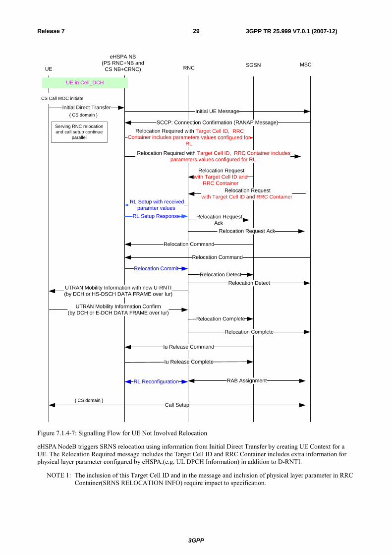
Figure 7.1.4-7: Signalling Flow for UE Not Involved Relocation
eHSPA NodeB triggers SRNS relocation using information from Initial Direct Transfer by creating UE Context for a UE. The Relocation Required message includes the Target Cell ID and RRC Container includes extra information for physical layer parameter configured by eHSPA.(e.g. UL DPCH Information) in addition to D-RNTI.
NOTE 1: The inclusion of this Target Cell ID and in the message and inclusion of physical layer parameter in RRC Container(SRNS RELOCATION INFO) require impact to specification.
3GPP
3GPP TR 25.999 V7.0.1 (2007-12)30Release 7
The legacy RNC receives Relocation Request with the parameters and execute RNSAP RL Setup procedure by setting received parameters in RRC Container into the Request message. Since the parameters configured for RL and Transport Channel are unchanged, the eHSPA Node B replies RL Setup Response without any modification to the RL resource for the UE.
After a reception of Relocation Commit from the eHSPA Node B, the legacy RNC sends UE RRC: UTRAN Mobility Information informs the UE the new U-RNTI.
NOTE 2: Parameters for Physical/Transport Channel are unchanged so this RRC message is the most appropriate.
RNSAP RL Reconfiguration procedure for establishing Transport Channel for CS RAB is triggered after the reception of RAB Assignment Request message establishes CS RAB.
Specification Changes:
There are the following changes identified in the specification for enabling the relocation:
- Change the presence of Target Cell ID in Source RNC to Target RNC Transport Container in RANAP: RELOCATION REQUIRED/RELOCATION REQUEST messages from conditional to optional for making source RNC to include the C-ID in RL Setup Request message in case of UE not involved relocation in addition to UE not involved relocation.
This change does not generate ASN.1 change since the presence of the Target Cell ID has been defined in current RANAP:
- Inclusion of Physical Layer parameter into RRC: SRNS RELOCATION INFO. The new parameters should be introduced in the IE would be:
- Maximum allowed UL TX power.
- Uplink DPCH info.
- E-DCH info.
- Downlink HS-PDSCH Information.
- Downlink information common for all radio links.
- Downlink information for each radio link.
- Details on the specification impact is FFS.
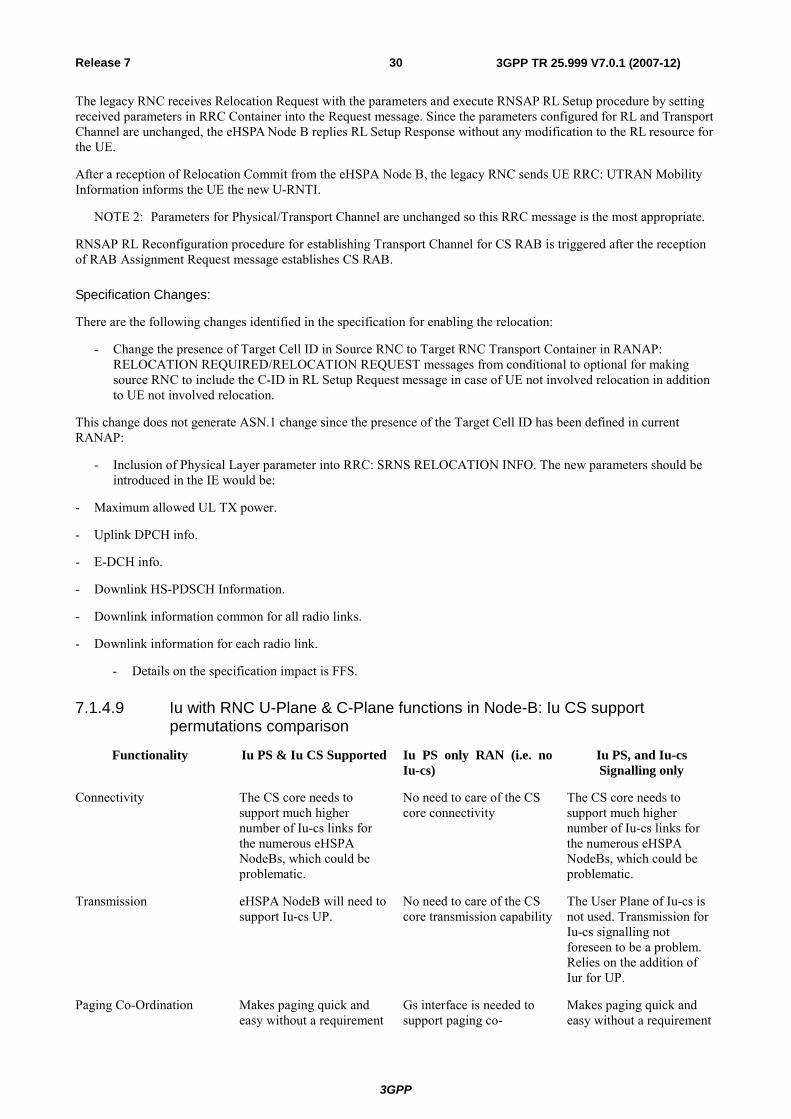
7.1.4.9 Iu with RNC U-Plane & C-Plane functions in Node-B: Iu CS support permutations comparison
Functionality Iu PS & Iu CS Supported Iu PS only RAN (i.e. no Iu-cs)
Iu PS, and Iu-cs Signalling only
Connectivity The CS core needs to support much higher number of Iu-cs links for the numerous eHSPA NodeBs, which could be problematic.
No need to care of the CS core connectivity
The CS core needs to support much higher number of Iu-cs links for the numerous eHSPA NodeBs, which could be problematic.
Transmission eHSPA NodeB will need to support Iu-cs UP.
No need to care of the CS core transmission capability
The User Plane of Iu-cs is not used. Transmission for Iu-cs signalling not foreseen to be a problem. Relies on the addition of Iur for UP.
Paging Co-Ordination Makes paging quick and easy without a requirement
Gs interface is needed to support paging co-
Makes paging quick and easy without a requirement
3GPP
3GPP TR 25.999 V7.0.1 (2007-12)31Release 7
Functionality Iu PS & Iu CS Supported Iu PS only RAN (i.e. no Iu-cs)
Iu PS, and Iu-cs Signalling only
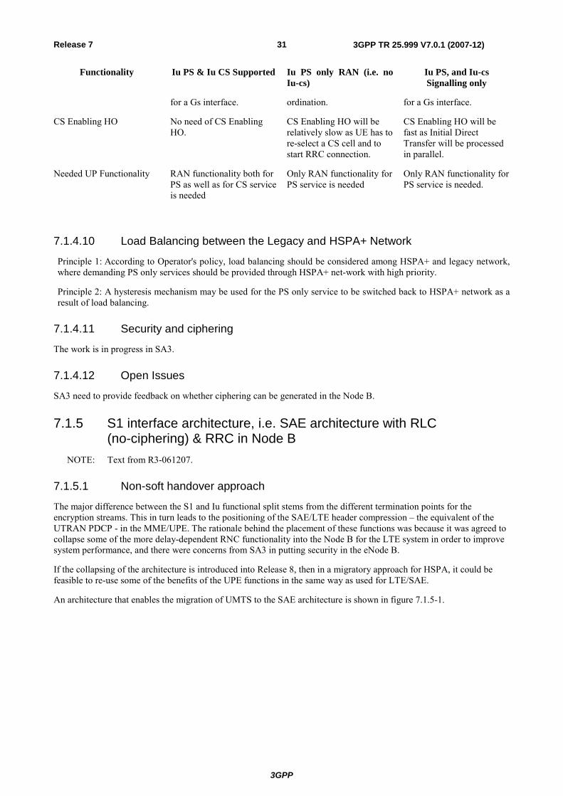
for a Gs interface. ordination. for a Gs interface.
CS Enabling HO No need of CS Enabling HO.
CS Enabling HO will be relatively slow as UE has to re-select a CS cell and to start RRC connection.
CS Enabling HO will be fast as Initial Direct Transfer will be processed in parallel.
Needed UP Functionality RAN functionality both for PS as well as for CS service is needed
Only RAN functionality for PS service is needed
Only RAN functionality for PS service is needed.
7.1.4.10 Load Balancing between the Legacy and HSPA+ Network
Principle 1: According to Operator's policy, load balancing should be considered among HSPA+ and legacy network, where demanding PS only services should be provided through HSPA+ net-work with high priority.
Principle 2: A hysteresis mechanism may be used for the PS only service to be switched back to HSPA+ network as a result of load balancing.
7.1.4.11 Security and ciphering
The work is in progress in SA3.
7.1.4.12 Open Issues
SA3 need to provide feedback on whether ciphering can be generated in the Node B.
7.1.5 S1 interface architecture, i.e. SAE architecture with RLC (no-ciphering) & RRC in Node B
NOTE: Text from R3-061207.
7.1.5.1 Non-soft handover approach
The major difference between the S1 and Iu functional split stems from the different termination points for the encryption streams. This in turn leads to the positioning of the SAE/LTE header compression – the equivalent of the UTRAN PDCP - in the MME/UPE. The rationale behind the placement of these functions was because it was agreed to collapse some of the more delay-dependent RNC functionality into the Node B for the LTE system in order to improve system performance, and there were concerns from SA3 in putting security in the eNode B.
If the collapsing of the architecture is introduced into Release 8, then in a migratory approach for HSPA, it could be feasible to re-use some of the benefits of the UPE functions in the same way as used for LTE/SAE.
An architecture that enables the migration of UMTS to the SAE architecture is shown in figure 7.1.5-1.
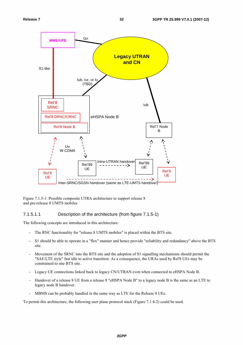
3GPP
3GPP TR 25.999 V7.0.1 (2007-12)32Release 7
Rel’8 UE
Rel’99 UE
Rel’8 Node B
eHSPA Node B Rel’8 DRNC/CRNC
Rel’8 SRNC
Uu W-CDMA
MME/UPE
S1-like
Legacy UTRAN and CN
Iub, Iur, or Iu (TBD)
Gn
Rel’7 Node B
Rel’99 UE
Iub
Rel’8 UE
Inter-SRNC/SGSN handover (same as LTE-UMTS handover)
Intra-UTRAN handover
Figure 7.1.5-1: Possible composite UTRA architecture to support release 8 and pre-release 8 UMTS mobiles
7.1.5.1.1 Description of the architecture (from figure 7.1.5-1)
The following concepts are introduced in this architecture:
- The RNC functionality for "release 8 UMTS mobiles" is placed within the BTS site.
- S1 should be able to operate in a "flex" manner and hence provide "reliability and redundancy" above the BTS site.
- Movement of the SRNC into the BTS site and the adoption of S1 signalling mechanisms should permit the "SAE/LTE style" fast idle to active transition. As a consequence, the URAs used by Rel'8 UEs may be constrained to one BTS site.
- Legacy UE connections linked back to legacy CN/UTRAN even when connected to eHSPA Node B.
- Handover of a release 8 UE from a release 8 "eHSPA Node B" to a legacy node B is the same as an LTE to legacy node B handover.
- MBMS can be probably handled in the same way as LTE for the Release 8 UEs.
To permit this architecture, the following user plane protocol stack (Figure 7.1.4-2) could be used.
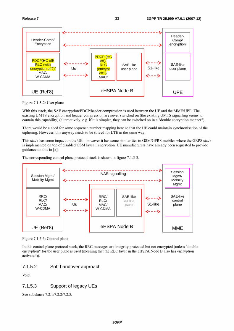
3GPP
3GPP TR 25.999 V7.0.1 (2007-12)33Release 7
eHSPA Node B
UPE
UE (Rel’8)
PDCP (HC off)/ RLC
(encrypt off?)/ MAC/
PDCP(HC off/
RLC (with encryption off?)/
MAC/ W-CDMA
Header-Comp/
Encryption
SAE-like user plane
SAE-like user plane
Header- Comp/
encryption
Uu S1-like
Figure 7.1.5-2: User plane
With this stack, the SAE encryption/PDCP/header compression is used between the UE and the MME/UPE. The existing UMTS encryption and header compression are never switched on (the existing UMTS signalling seems to contain this capability) (alternatively, e.g. if it is simpler, they can be switched on in a "double encryption manner").
There would be a need for some sequence number mapping here so that the UE could maintain synchronisation of the ciphering. However, this anyway needs to be solved for LTE in the same way.
This stack has some impact on the UE – however it has some similarities to GSM/GPRS mobiles where the GRPS stack is implemented on top of disabled GSM layer 1 encryption. UE manufacturers have already been requested to provide guidance on this in [x].
The corresponding control plane protocol stack is shown in figure 7.1.5-3.
eHSPA Node B
MME
UE (Rel’8)
RRC/ RLC/ MAC/
W-CDMA
RRC/ RLC/ MAC/
W-CDMA
Session Mgmt/ Mobility Mgmt
SAE-like control plane
SAE-like control plane
Session Mgmt/
Mobility Mgmt
NAS signalling
Uu S1-like
Figure 7.1.5-3: Control plane
In this control plane protocol stack, the RRC messages are integrity protected but not encrypted (unless "double encryption" for the user plane is used (meaning that the RLC layer in the eHSPA Node B also has encryption activated)).
7.1.5.2 Soft handover approach
Void.
7.1.5.3 Support of legacy UEs
See subclause 7.2.1/7.2.2/7.2.3.
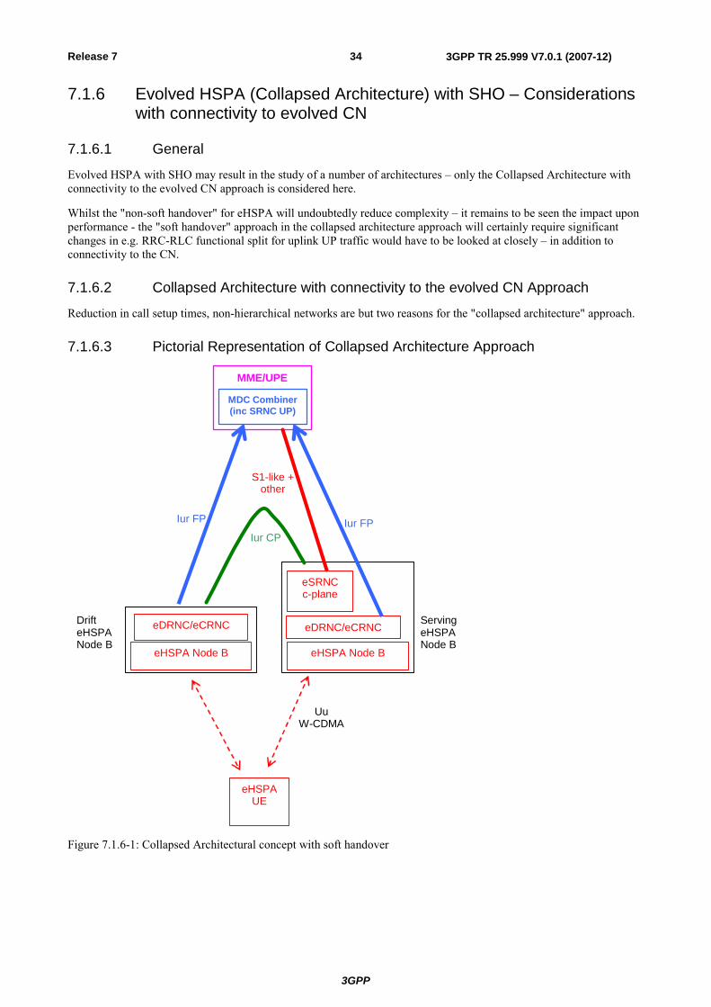
3GPP
3GPP TR 25.999 V7.0.1 (2007-12)34Release 7
7.1.6 Evolved HSPA (Collapsed Architecture) with SHO – Considerations with connectivity to evolved CN
7.1.6.1 General
Evolved HSPA with SHO may result in the study of a number of architectures – only the Collapsed Architecture with connectivity to the evolved CN approach is considered here.
Whilst the "non-soft handover" for eHSPA will undoubtedly reduce complexity – it remains to be seen the impact upon performance - the "soft handover" approach in the collapsed architecture approach will certainly require significant changes in e.g. RRC-RLC functional split for uplink UP traffic would have to be looked at closely – in addition to connectivity to the CN.
7.1.6.2 Collapsed Architecture with connectivity to the evolved CN Approach
Reduction in call setup times, non-hierarchical networks are but two reasons for the "collapsed architecture" approach.
7.1.6.3 Pictorial Representation of Collapsed Architecture Approach
eHSPA UE
eHSPA Node B
Serving eHSPA Node B
eDRNC/eCRNC
eSRNC c-plane
Uu W-CDMA
MME/UPE
S1-like + other
eHSPA Node B
eDRNC/eCRNC
MDC Combiner(inc SRNC UP)
Iur CP Iur FP Iur FP
Drift eHSPA Node B
Figure 7.1.6-1: Collapsed Architectural concept with soft handover
3GPP
3GPP TR 25.999 V7.0.1 (2007-12)35Release 7
7.1.6.4 Description of architecture
All of the following concepts are introduced in the architecture outlined above. The CRNC and the radio protocol control plane SRNC functionality for "eHPSA UMTS mobiles" are placed within the BTS site:
- Collapsing the whole SRNC would mean that there would be a new outer ARQ above the layer that is doing the macro-diversity combining between Node Bs.
- Requiring RLC to sit on top of MDC - to handle any necessary retransmissions - enables the maintenance of the closed-loop approach to RLC Acknowledged Mode, whilst still allowing to provide feedback to the Node B on the required SIR targets.
- One approach to solve this is to split the RLC entities between the RLC transporting the RRC signalling radio bearers, and the RLC transporting the radio bearers for user data. It may even be possible to split the RLC control channel and RLC data channel onto different logical channels (this should be verified).
- RRC and (at least RLC for the RRC Signalling radio bearers) in serving eHSPA Node B. This means that the RRC part of call setup time can be minimised based on its location. It also means that RRC does NOT get the benefit of soft handover. However it is likely that the capacity reduction because of this could be small.
- RLC user plane and MAC-es (combiner) placed in UPE. This allows not having to relay user plane back down to the serving eHSPA Node B (and thus increasing RLC RTT), hence allowing RLC round-trip time to be maintained as in Release 7.
NOTE 1: it is FFS as to whether the RLC downlink AM entity can be placed in the serving Node B allowing faster RTT for DL data. This would require a higher power offset for the UL RLC control channel, as it is essential that RLC performance does not get degraded. This should be discussed further by RAN2.
- Iur control plane (i.e. RNSAP) connected transparently between serving eHSPA Node B and non-serving eHSPA Node B. This is indicated in GREEN in figure 7.1.6-1.
- This is needed for admission/congestion control and radio link management.
- Iur user plane (i.e. Frame Protocol (FP)) connection between UPE and serving eHSPA Node B, and respectively UPE and non-serving eHSPA Node B. This is indicated in BLUE in figure 7.1.6-1.
- It is likely that much of the existing protocol stack could be re-used from the eHSPA Node B point of view. However some indication of the end RLC PDU error rate would need to be provided back to the eHSPA Node B such that RRC can update the uplink SIR target.
NOTE 2: If the MDC were not part of the MDC, there would need to be another interface to allow connectivity between MDC and UPE. This would also require the MME-eHSPA Node B and MDC-eHSPA Node B control signalling to be separated.
- S1-like interface between MME/UPE and serving eHSPA Node B. This is indicated in RED in figure 7.1.6-1.
- This interface would need to be UPDATED to ensure that the functional split between RRC and RLC is well-specified. This would mean that when soft handover is initiated between eHSPA Node B's, the SRNC would need to inform the UPE to establish a new user plane connection to the diversity eHSPA Node B. Also the MAC-es configuration would need to be agreed between UPE and eHSPA Node B
- Soft handover cannot be performed for eHSPA UEs between eHSPA Node B and Release 7 Node B.
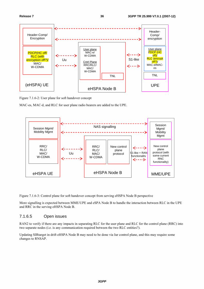
3GPP
3GPP TR 25.999 V7.0.1 (2007-12)36Release 7
eHSPA Node B
UPE
(eHSPA) UE
User plane MAC-e/
W-CDMA
Cntrl Plane RRC/RLC/
MAC/ W-CDMA
PDCP(HC off/
RLC (with encryption off?)/
MAC/ W-CDMA
Header-Comp/
Encryption
TNL
User plane PDCP (HC
off)/ RLC (encrypt
off?)/ MAC-d/MAC-
es
Header- Comp/
encryption
Uu S1-like
TNL
Figure 7.1.6-2: User plane for soft handover concept
MAC-es, MAC-d, and RLC for user plane radio bearers are added to the UPE.
eHSPA Node B
MME/UPE
eHSPA UE
RRC/ RLC/ MAC/
W-CDMA
RRC/ RLC/ MAC/
W-CDMA
Session Mgmt/ Mobility Mgmt
New control
plane protocol
New control
plane protocol (with some current
RNC functionality)
Session Mgmt/
Mobility Mgmt
NAS signalling
Uu S1-like + RAN functionality
Figure 7.1.6-3: Control plane for soft handover concept from serving eHSPA Node B perspective
More signalling is expected between MME/UPE and eSPA Node B to handle the interaction between RLC in the UPE and RRC in the serving eHSPA Node B.
7.1.6.5 Open issues
RAN2 to verify if there are any impacts in separating RLC for the user plane and RLC for the control plane (RRC) into two separate nodes (i.e. is any communication required between the two RLC entities?).
Updating SIRtarget in drift eHSPA Node B may need to be done via Iur control plane, and this may require some changes to RNSAP.
3GPP
3GPP TR 25.999 V7.0.1 (2007-12)37Release 7
7.1.7 Enhanced SRNS relocation procedure This section proposes enhancements to the SRNS relocation procedure both in case of network-controlled mobility (i.e. Handover procedure) and UE-controlled mobility (i.e. Cell Update procedure). The proposed enhancements can help reduce both handover delay and processing load at the CN. This is especially useful when considering the flat UTRAN architecture option which will extensively use the SRNS relocation procedure to handle inter-Node B+ mobility.
The procedure does not require changes on the air interface, and therefore is backward compatible with the legacy UEs. Also, the approach adopted is similar to the approach used in LTE to handle inter-eNB mobility. This will probably allow some CN reutilization between LTE and HPSA+.
7.1.7.1 Network-controlled Mobility
Figure 7.1.7-1 shows the signaling flow for the enhanced SRNS relocation procedure when this is performed in combination with hard handover. In particular the following steps apply:
1) Based on measurement reports from the UE (and possibly some other RRM specific information), the source Node B+ decides to handover the UE to a cell controlled by the target Node B+.
2) The source Node B+ issues a Relocation Request to the target Node B+ passing the necessary information (context transfer) to prepare the HO at the target side. After performing Admission Control, the target Node B+ configures the required resources.
3) The Relocation Response message is sent to the source Node B+ with the necessary information for the UE to reconfigure the radio path towards the target Node B+.
4) The PHYSICAL CHANNEL RECONFIGURATION message is sent by the source Node B+ with the information to access the cell in the target Node B+.
A) The source Node B+ can start forwarding GTP-PDUs of the different RABs to the target Node B+, depending on their QoS Profile.
5) Physical layer synchronization and radio link establishment are performed with the target cell in the target Node B+.
6) The UE sends a PHYSICAL CHANNEL RECONFIGURATION COMPLETE message to the target cell in the target Node B+.
7) The target Node B+ sends a Relocation Complete message to the CN with a request to establish the different RABs between target Node B+ and CN.
8) The CN responds with a Relocation Complete Acknowledge message and starts to forward the data in the new path.
9) The target Node B+ finally initiates the release of the resources in the source Node B+.
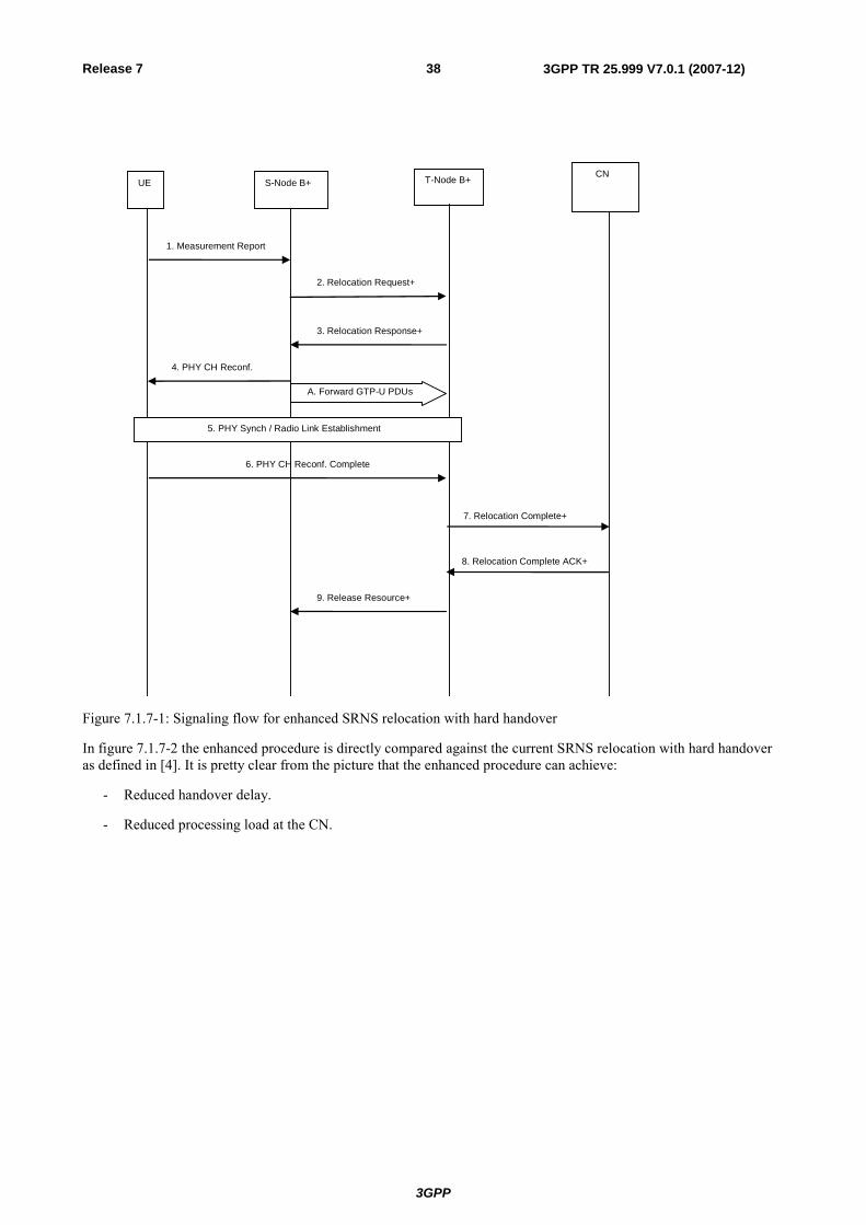
3GPP
3GPP TR 25.999 V7.0.1 (2007-12)38Release 7
4. PHY CH Reconf.
3. Relocation Response+
UE CN
S-Node B+
2. Relocation Request+
7. Relocation Complete+
T-Node B+
1. Measurement Report
A. Forward GTP-U PDUs
5. PHY Synch / Radio Link Establishment
6. PHY CH Reconf. Complete
8. Relocation Complete ACK+
9. Release Resource+
Figure 7.1.7-1: Signaling flow for enhanced SRNS relocation with hard handover
In figure 7.1.7-2 the enhanced procedure is directly compared against the current SRNS relocation with hard handover as defined in [4]. It is pretty clear from the picture that the enhanced procedure can achieve:
- Reduced handover delay.
- Reduced processing load at the CN.
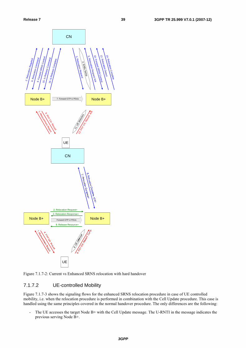
3GPP
3GPP TR 25.999 V7.0.1 (2007-12)39Release 7
CN
Node B+
UE
8. PHY CH. Reconf.
2. R
eloc
atio
n R
equi
red
3. Relocation R
equest
5. Relocation R
equest Ack
4. RABs Setup
7. Forward GTP-U PDUs
6. R
eloc
atio
n C
omm
and
13. P
HY C
H. R
econ
f. Ac
k1. Measurem
ent Report
9. F
orw
ard
SRN
S C
onte
xt
10. Forward SR
NS C
ontext
11. U
E de
tecti
on
12. Relocation D
etect
16. I
u R
elea
se C
ompl
ete
14. Relocation C
omplete
Node B+
15. I
u R
elea
se C
omm
and
CN
Node B+
UE
Forward GTP-U PDUs Node B+
2. Relocation Request+
3. Relocation Response+
9. Release Resource+
Figure 7.1.7-2: Current vs Enhanced SRNS relocation with hard handover
7.1.7.2 UE-controlled Mobility
Figure 7.1.7-3 shows the signaling flows for the enhanced SRNS relocation procedure in case of UE controlled mobility, i.e. when the relocation procedure is performed in combination with the Cell Update procedure. This case is handled using the same principles covered in the normal handover procedure. The only differences are the following:
- The UE accesses the target Node B+ with the Cell Update message. The U-RNTI in the message indicates the previous serving Node B+.
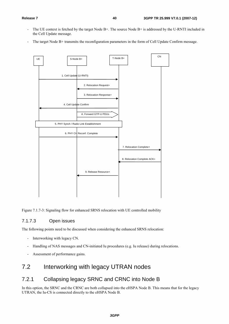
3GPP
3GPP TR 25.999 V7.0.1 (2007-12)40Release 7
- The UE context is fetched by the target Node B+. The source Node B+ is addressed by the U-RNTI included in the Cell Update message.
- The target Node B+ transmits the reconfiguration parameters in the form of Cell Update Confirm message.
4. Cell Update Confirm
3. Relocation Response+
UE CN
S-Node B+
2. Relocation Request+
7. Relocation Complete+
T-Node B+
1. Cell Update (U-RNTI)
A. Forward GTP-U PDUs
5. PHY Synch / Radio Link Establishment
6. PHY CH Reconf. Complete
8. Relocation Complete ACK+
9. Release Resource+
Figure 7.1.7-3: Signaling flow for enhanced SRNS relocation with UE controlled mobility
7.1.7.3 Open issues
The following points need to be discussed when considering the enhanced SRNS relocation:
- Interworking with legacy CN.
- Handling of NAS messages and CN-initiated Iu procedures (e.g. Iu release) during relocations.
- Assessment of performance gains.
7.2 Interworking with legacy UTRAN nodes
7.2.1 Collapsing legacy SRNC and CRNC into Node B In this option, the SRNC and the CRNC are both collapsed into the eHSPA Node B. This means that for the legacy UTRAN, the Iu-CS is connected directly to the eHSPA Node B.
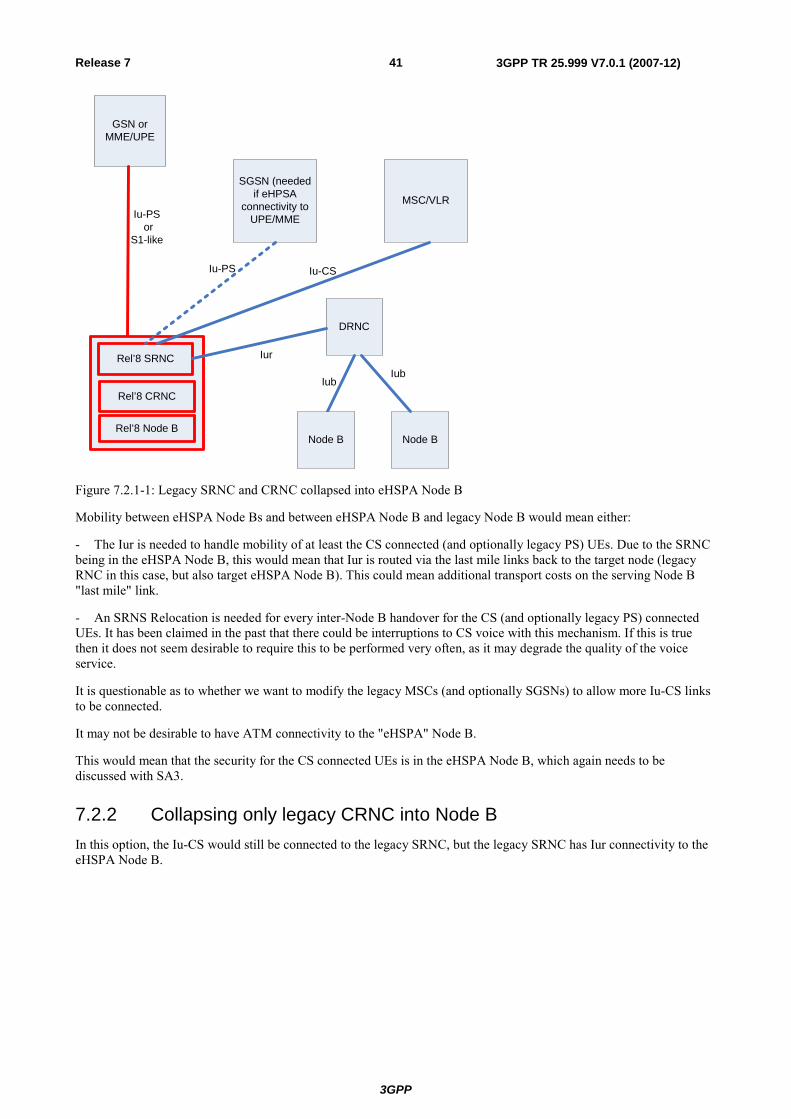
3GPP
3GPP TR 25.999 V7.0.1 (2007-12)41Release 7
GSN or MME/UPE
SGSN (needed if eHPSA
connectivity to UPE/MME
MSC/VLR
Iu-CSIu-PS
Iu-PS or
S1-like
Rel’8 Node B
Rel’8 CRNC
Rel’8 SRNC
DRNC
Iur
Node B
Iub
Node B
Iub
Figure 7.2.1-1: Legacy SRNC and CRNC collapsed into eHSPA Node B
Mobility between eHSPA Node Bs and between eHSPA Node B and legacy Node B would mean either:
- The Iur is needed to handle mobility of at least the CS connected (and optionally legacy PS) UEs. Due to the SRNC being in the eHSPA Node B, this would mean that Iur is routed via the last mile links back to the target node (legacy RNC in this case, but also target eHSPA Node B). This could mean additional transport costs on the serving Node B "last mile" link.
- An SRNS Relocation is needed for every inter-Node B handover for the CS (and optionally legacy PS) connected UEs. It has been claimed in the past that there could be interruptions to CS voice with this mechanism. If this is true then it does not seem desirable to require this to be performed very often, as it may degrade the quality of the voice service.
It is questionable as to whether we want to modify the legacy MSCs (and optionally SGSNs) to allow more Iu-CS links to be connected.
It may not be desirable to have ATM connectivity to the "eHSPA" Node B.
This would mean that the security for the CS connected UEs is in the eHSPA Node B, which again needs to be discussed with SA3.
7.2.2 Collapsing only legacy CRNC into Node B In this option, the Iu-CS would still be connected to the legacy SRNC, but the legacy SRNC has Iur connectivity to the eHSPA Node B.
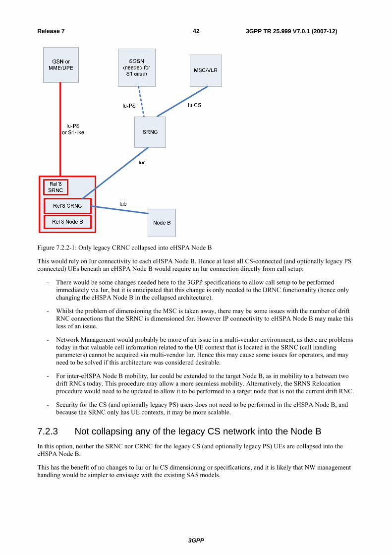
3GPP
3GPP TR 25.999 V7.0.1 (2007-12)42Release 7
Figure 7.2.2-1: Only legacy CRNC collapsed into eHSPA Node B
This would rely on Iur connectivity to each eHSPA Node B. Hence at least all CS-connected (and optionally legacy PS connected) UEs beneath an eHSPA Node B would require an Iur connection directly from call setup:
- There would be some changes needed here to the 3GPP specifications to allow call setup to be performed immediately via Iur, but it is anticipated that this change is only needed to the DRNC functionality (hence only changing the eHSPA Node B in the collapsed architecture).
- Whilst the problem of dimensioning the MSC is taken away, there may be some issues with the number of drift RNC connections that the SRNC is dimensioned for. However IP connectivity to eHSPA Node B may make this less of an issue.
- Network Management would probably be more of an issue in a multi-vendor environment, as there are problems today in that valuable cell information related to the UE context that is located in the SRNC (call handling parameters) cannot be acquired via multi-vendor Iur. Hence this may cause some issues for operators, and may need to be solved if this architecture was considered desirable.
- For inter-eHSPA Node B mobility, Iur could be extended to the target Node B, as in mobility to a between two drift RNCs today. This procedure may allow a more seamless mobility. Alternatively, the SRNS Relocation procedure would need to be updated to allow it to be performed to a target node that is not the current drift RNC.
- Security for the CS (and optionally legacy PS) users does not need to be performed in the eHSPA Node B, and because the SRNC only has UE contexts, it may be more scalable.
7.2.3 Not collapsing any of the legacy CS network into the Node B In this option, neither the SRNC nor CRNC for the legacy CS (and optionally legacy PS) UEs are collapsed into the eHSPA Node B.
This has the benefit of no changes to Iur or Iu-CS dimensioning or specifications, and it is likely that NW management handling would be simpler to envisage with the existing SA5 models.
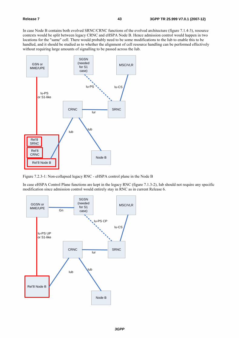
3GPP
3GPP TR 25.999 V7.0.1 (2007-12)43Release 7
In case Node B contains both evolved SRNC/CRNC functions of the evolved architecture (figure 7.1.4-3), resource contexts would be split between legacy CRNC and eHSPA Node B. Hence admission control would happen in two locations for the "same" cell. There would probably need to be some modifications to the Iub to enable this to be handled, and it should be studied as to whether the alignment of cell resource handling can be performed effectively without requiring large amounts of signalling to be passed across the Iub.
GSN or MME/UPE
SGSN (needed for S1 case)
MSC/VLR
Iu-CSIu-PS
Rel’8 Node B
CRNC
Rel’8 SRNC
SRNCIur
Iu-PS or S1-like
Rel’8 CRNC
Iub
Node B
Iub
Figure 7.2.3-1: Non-collapsed legacy RNC - eHSPA control plane in the Node B
In case eHSPA Control Plane functions are kept in the legacy RNC (figure 7.1.3-2), Iub should not require any specific modification since admission control would entirely stay in RNC as in current Release 6.
GGSN or MME/UPE
SGSN (needed for S1 case)
MSC/VLR
Iu-CS
Iu-PS CP
Rel’8 Node B
CRNC SRNCIur
Iu-PS UPor S1-like
Iub
Node B
Iub
Gn
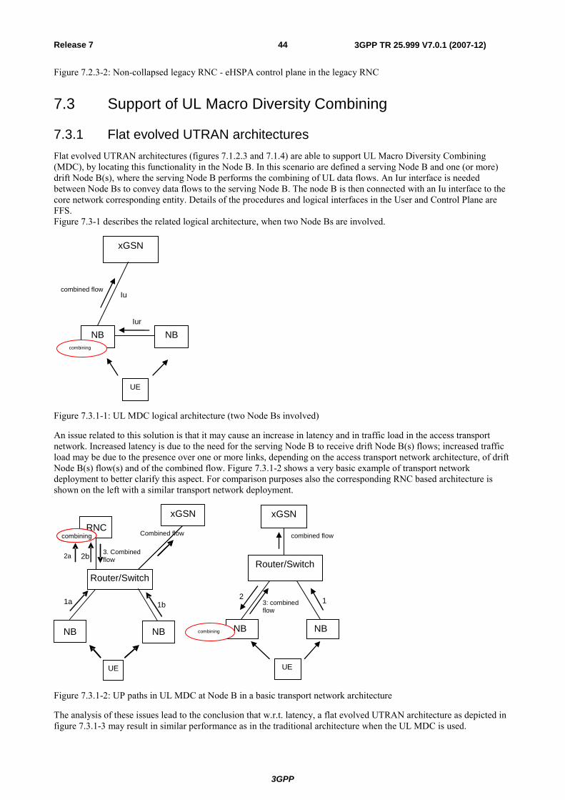
3GPP
3GPP TR 25.999 V7.0.1 (2007-12)44Release 7
Figure 7.2.3-2: Non-collapsed legacy RNC - eHSPA control plane in the legacy RNC
7.3 Support of UL Macro Diversity Combining
7.3.1 Flat evolved UTRAN architectures Flat evolved UTRAN architectures (figures 7.1.2.3 and 7.1.4) are able to support UL Macro Diversity Combining (MDC), by locating this functionality in the Node B. In this scenario are defined a serving Node B and one (or more) drift Node B(s), where the serving Node B performs the combining of UL data flows. An Iur interface is needed between Node Bs to convey data flows to the serving Node B. The node B is then connected with an Iu interface to the core network corresponding entity. Details of the procedures and logical interfaces in the User and Control Plane are FFS. Figure 7.3-1 describes the related logical architecture, when two Node Bs are involved.
xGSN
NB NB
UE
combining
combined flow
Iur
Iu
Figure 7.3.1-1: UL MDC logical architecture (two Node Bs involved)
An issue related to this solution is that it may cause an increase in latency and in traffic load in the access transport network. Increased latency is due to the need for the serving Node B to receive drift Node B(s) flows; increased traffic load may be due to the presence over one or more links, depending on the access transport network architecture, of drift Node B(s) flow(s) and of the combined flow. Figure 7.3.1-2 shows a very basic example of transport network deployment to better clarify this aspect. For comparison purposes also the corresponding RNC based architecture is shown on the left with a similar transport network deployment.
Router/Switch
NB NB
UE
3: combined flow
2 1
xGSN
combining
combined flow
UE
RNC combining
xGSN
1a 1b
2b 3. Combined flow
NB NB
Router/Switch
UE UE
combining
2a
Combined flow
Figure 7.3.1-2: UP paths in UL MDC at Node B in a basic transport network architecture
The analysis of these issues lead to the conclusion that w.r.t. latency, a flat evolved UTRAN architecture as depicted in figure 7.3.1-3 may result in similar performance as in the traditional architecture when the UL MDC is used.
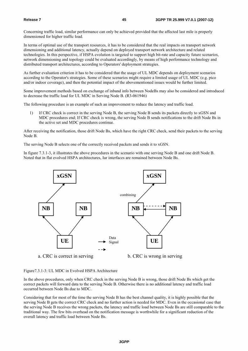
3GPP
3GPP TR 25.999 V7.0.1 (2007-12)45Release 7
Concerning traffic load, similar performance can only be achieved provided that the affected last mile is properly dimensioned for higher traffic load.
In terms of optimal use of the transport resources, it has to be considered that the real impacts on transport network dimensioning and additional latency, actually depend on deployed transport network architecture and related technologies. In this perspective, if HSPA evolution is targeted to support high bit-rate and capacity future scenarios, network dimensioning and topology could be evaluated accordingly, by means of high performance technology and distributed transport architectures, according to Operators' deployment strategies.
As further evaluation criterion it has to be considered that the usage of UL MDC depends on deployment scenarios according to the Operator's strategies. Some of these scenarios might require a limited usage of UL MDC (e.g. pico and/or indoor coverage), and then the potential impact of the abovementioned issues would be further limited.
Some improvement methods based on exchange of inband info between NodeBs may also be considered and introduced to decrease the traffic load for UL MDC in Serving Node B. (R3-061946)
The following procedure is an example of such an improvement to reduce the latency and traffic load.
1) If CRC check is correct in the serving Node B, the serving Node B sends its packets directly to xGSN and MDC procedures end; If CRC check is wrong, the serving Node B sends notifications to the drift Node Bs in the active set and MDC procedures continue.
After receiving the notification, those drift Node Bs, which have the right CRC check, send their packets to the serving Node B.
The serving Node B selects one of the correctly received packets and sends it to xGSN.
In figure 7.3.1-3, it illustrates the above procedures in the scenario with one serving Node B and one drift Node B. Noted that in flat evolved HSPA architectures, Iur interfaces are remained between Node Bs.
combining
xGSN
NB NB
UE
xGSN
NB NB
UE
a. CRC is correct in serving b. CRC is wrong in serving
Data Signal
Figure7.3.1-3: UL MDC in Evolved HSPA Architecture
In the above procedures, only when CRC check in the serving Node B is wrong, those drift Node Bs which get the correct packets will forward data to the serving Node B. Otherwise there is no additional latency and traffic load occurred between Node Bs due to MDC.
Considering that for most of the time the serving Node B has the best channel quality, it is highly possible that the serving Node B gets the correct CRC check and no further action is needed for MDC. Even in the occasional case that the serving Node B receives the wrong packets, the latency and traffic load between Node Bs are still comparable to the traditional way. The few bits overhead on the notification message is worthwhile for a significant reduction of the overall latency and traffic load between Node Bs.
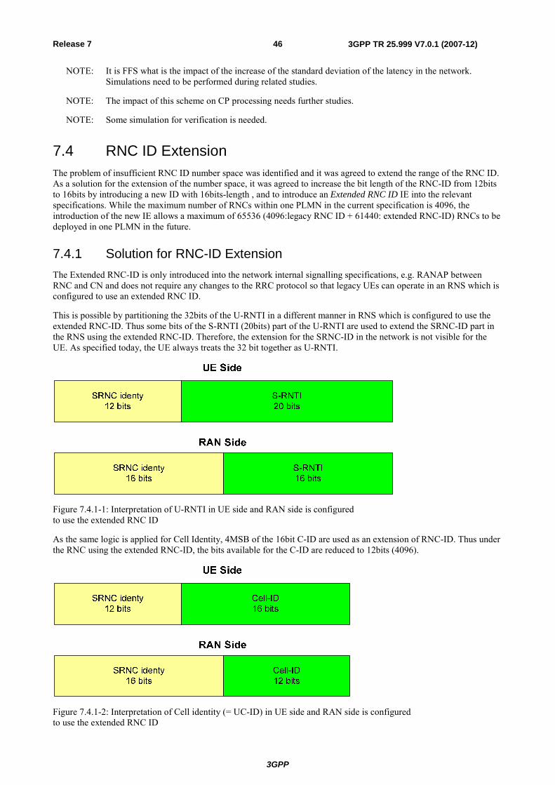
3GPP
3GPP TR 25.999 V7.0.1 (2007-12)46Release 7
NOTE: It is FFS what is the impact of the increase of the standard deviation of the latency in the network. Simulations need to be performed during related studies.
NOTE: The impact of this scheme on CP processing needs further studies.
NOTE: Some simulation for verification is needed.
7.4 RNC ID Extension The problem of insufficient RNC ID number space was identified and it was agreed to extend the range of the RNC ID. As a solution for the extension of the number space, it was agreed to increase the bit length of the RNC-ID from 12bits to 16bits by introducing a new ID with 16bits-length , and to introduce an Extended RNC ID IE into the relevant specifications. While the maximum number of RNCs within one PLMN in the current specification is 4096, the introduction of the new IE allows a maximum of 65536 (4096:legacy RNC ID + 61440: extended RNC-ID) RNCs to be deployed in one PLMN in the future.
7.4.1 Solution for RNC-ID Extension The Extended RNC-ID is only introduced into the network internal signalling specifications, e.g. RANAP between RNC and CN and does not require any changes to the RRC protocol so that legacy UEs can operate in an RNS which is configured to use an extended RNC ID.
This is possible by partitioning the 32bits of the U-RNTI in a different manner in RNS which is configured to use the extended RNC-ID. Thus some bits of the S-RNTI (20bits) part of the U-RNTI are used to extend the SRNC-ID part in the RNS using the extended RNC-ID. Therefore, the extension for the SRNC-ID in the network is not visible for the UE. As specified today, the UE always treats the 32 bit together as U-RNTI.
Figure 7.4.1-1: Interpretation of U-RNTI in UE side and RAN side is configured to use the extended RNC ID
As the same logic is applied for Cell Identity, 4MSB of the 16bit C-ID are used as an extension of RNC-ID. Thus under the RNC using the extended RNC-ID, the bits available for the C-ID are reduced to 12bits (4096).
Figure 7.4.1-2: Interpretation of Cell identity (= UC-ID) in UE side and RAN side is configured to use the extended RNC ID
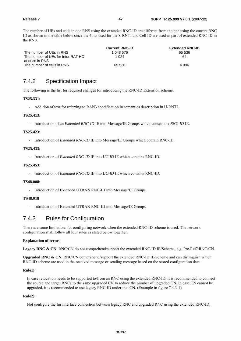
3GPP
3GPP TR 25.999 V7.0.1 (2007-12)47Release 7
The number of UEs and cells in one RNS using the extended RNC-ID are different from the one using the current RNC ID as shown in the table below since the 4bits used for the S-RNTI and Cell ID are used as part of extended RNC-ID in the RNS.
Current RNC-ID Extended RNC-ID The number of UEs in RNS 1 048 576 65 536 The number of UEs for Inter-RAT HO at once in RNS
1 024 64
The number of cells in RNS 65 536 4 096
7.4.2 Specification Impact The following is the list for required changes for introducing the RNC-ID Extension scheme.
TS25.331:
- Addition of text for referring to RAN3 specification in semantics description in U-RNTI.
TS25.413:
- Introduction of an Extended RNC-ID IE into Message/IE Groups which contain the RNC-ID IE.
TS25.423:
- Introduction of Extended RNC-ID IE into Message/IE Groups which contain RNC-ID.
TS25.433:
- Introduction of Extended RNC-ID IE into UC-ID IE which contains RNC-ID.
TS25.453:
- Introduction of Extended RNC-ID IE into UC-ID IE which contains RNC-ID.
TS48.008:
- Introduction of Extended UTRAN RNC-ID into Message/IE Groups.
TS48.018
- Introduction of Extended UTRAN RNC-ID into Message/IE Groups.
7.4.3 Rules for Configuration There are some limitations for configuring network when the extended RNC-ID scheme is used. The network configuration shall follow all four rules as stated below together.
Explanation of terms
Legacy RNC & CN: RNC/CN do not comprehend/support the extended RNC-ID IE/Scheme, e.g. Pre-Rel7 RNC/CN.
Upgraded RNC & CN: RNC/CN comprehend/support the extended RNC-ID IE/Scheme and can distinguish which RNC-ID scheme are used in the received message or sending message based on the stored configuration data.
Rule1):
In case relocation needs to be supported to/from an RNC using the extended RNC-ID, it is recommended to connect the source and target RNCs to the same upgraded CN to reduce the number of upgraded CN. In case CN cannot be upgraded, it is recommended to use legacy RNC-ID under that CN. (Example in figure 7.4.3-1)
Rule2):
Not configure the Iur interface connection between legacy RNC and upgraded RNC using the extended RNC-ID.
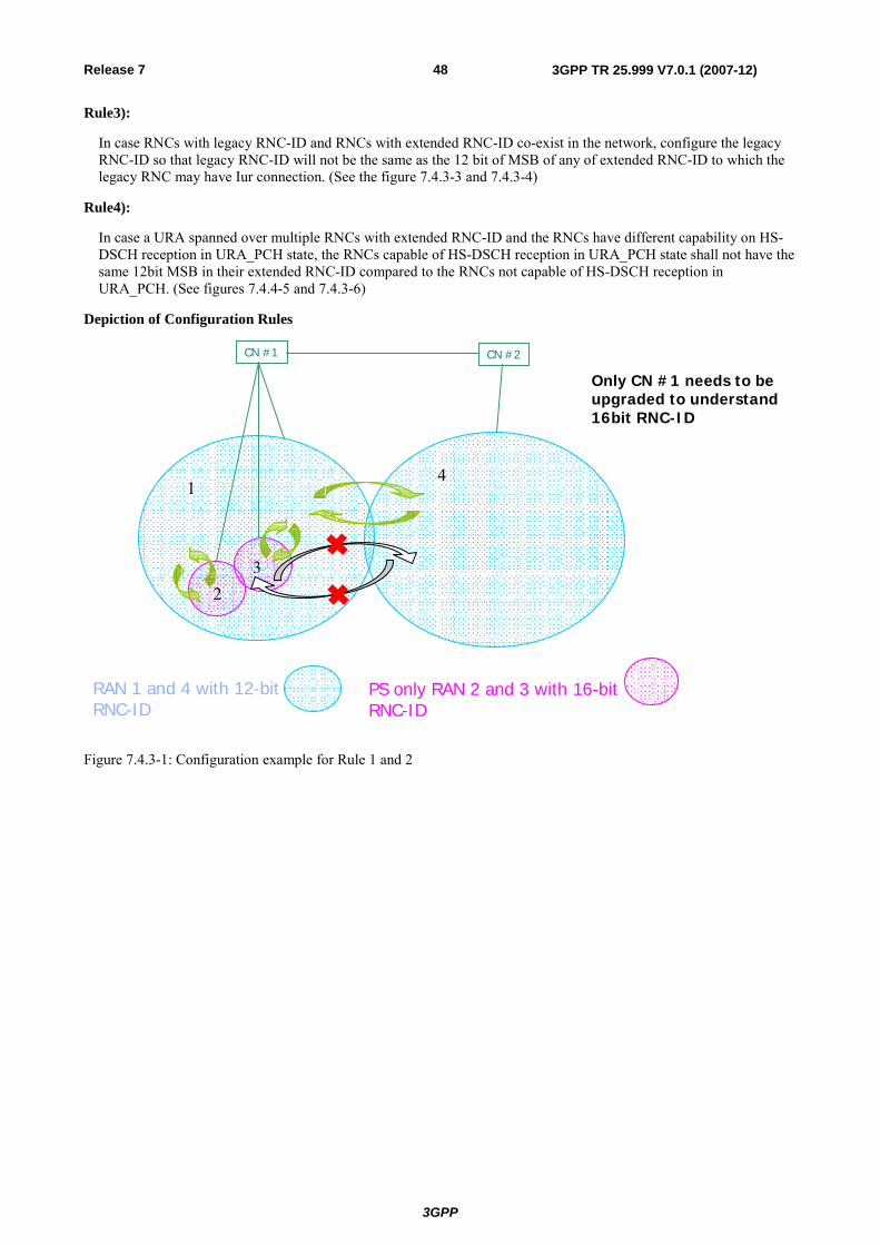
3GPP
3GPP TR 25.999 V7.0.1 (2007-12)48Release 7
Rule3):
In case RNCs with legacy RNC-ID and RNCs with extended RNC-ID co-exist in the network, configure the legacy RNC-ID so that legacy RNC-ID will not be the same as the 12 bit of MSB of any of extended RNC-ID to which the legacy RNC may have Iur connection. (See the figure 7.4.3-3 and 7.4.3-4)
Rule4):
In case a URA spanned over multiple RNCs with extended RNC-ID and the RNCs have different capability on HS-DSCH reception in URA_PCH state, the RNCs capable of HS-DSCH reception in URA_PCH state shall not have the same 12bit MSB in their extended RNC-ID compared to the RNCs not capable of HS-DSCH reception in URA_PCH. (See figures 7.4.4-5 and 7.4.3-6)
Depiction of Configuration Rules
PS only RAN 2 and 3 with 16-bit RNC-ID
RAN 1 and 4 with 12-bit RNC-ID
CN #1 CN #2
Only CN #1 needs to be upgraded to understand 16bit RNC-ID
14
32
Figure 7.4.3-1: Configuration example for Rule 1 and 2
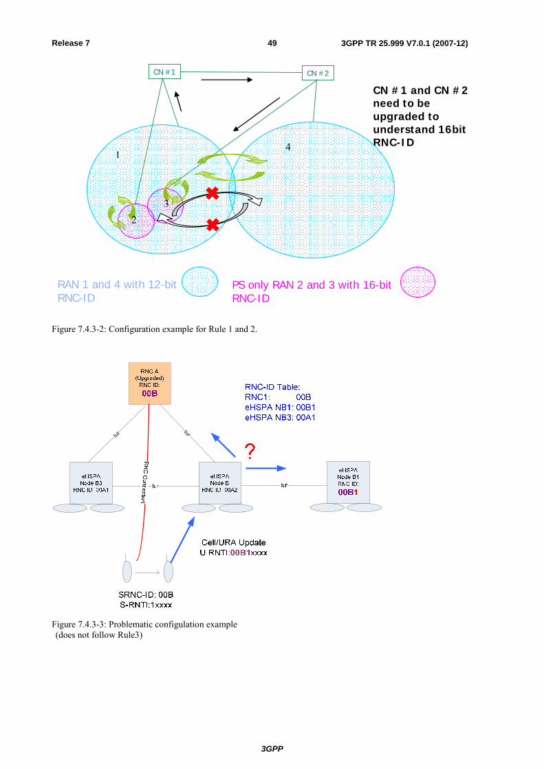
3GPP
3GPP TR 25.999 V7.0.1 (2007-12)49Release 7
PS only RAN 2 and 3 with 16-bit RNC-ID
RAN 1 and 4 with 12-bit RNC-ID
CN #1 CN #2
CN #1 and CN #2 need to be upgraded to understand 16bit RNC-ID 1
2 3
4
Figure 7.4.3-2: Configuration example for Rule 1 and 2.
IurIur
Figure 7.4.3-3: Problematic configulation example (does not follow Rule3)
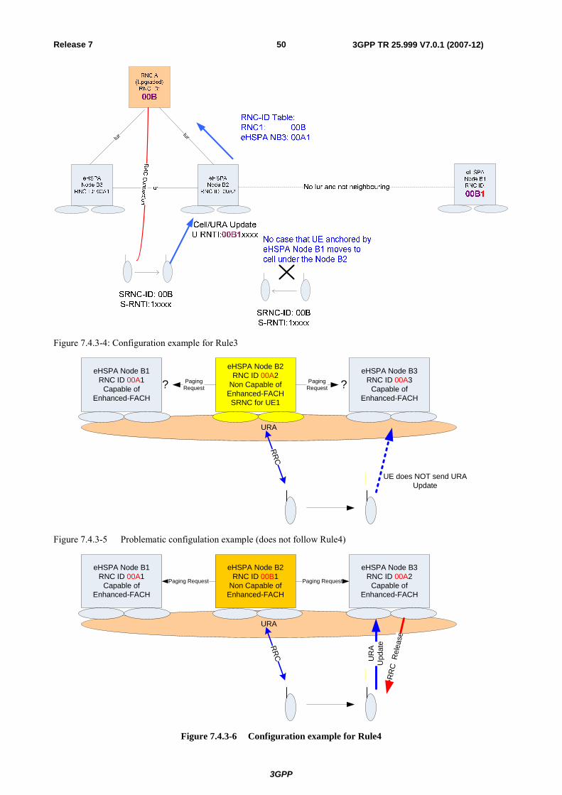
3GPP
3GPP TR 25.999 V7.0.1 (2007-12)50Release 7
IurIur
Figure 7.4.3-4: Configuration example for Rule3
URA
eHSPA Node B1RNC ID 00A1
Capable of Enhanced-FACH
eHSPA Node B2RNC ID 00A2
Non Capable of Enhanced-FACHSRNC for UE1
eHSPA Node B3RNC ID 00A3
Capable of Enhanced-FACH
UE does NOT send URA Update
Paging Request
Paging Request ??
RR
C
Figure 7.4.3-5 Problematic configulation example (does not follow Rule4)
URA
eHSPA Node B1RNC ID 00A1
Capable of Enhanced-FACH
eHSPA Node B3RNC ID 00A2
Capable of Enhanced-FACH
UR
A U
pdat
e
Paging RequestPaging Request
RR
C
eHSPA Node B2RNC ID 00B1
Non Capable of Enhanced-FACH
RR
C R
elea
se
Figure 7.4.3-6 Configuration example for Rule4
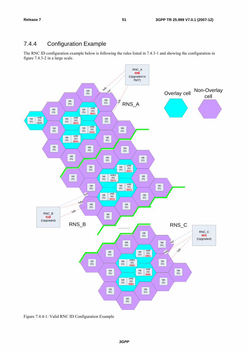
3GPP
3GPP TR 25.999 V7.0.1 (2007-12)51Release 7
7.4.4 Configuration Example The RNC ID configuration example below is following the rules listed in 7.4.3-1 and showing the configuration in figure 7.4.3-2 in a large scale.
eNB(f2)
00A1
NB(f1)
NB(f1)
NB(f1)
NB(f1)
NB(f1)
eNB(f2)
00A2
NB(f1)
NB(f1)
NB(f1)
NB(f1)
eNB(f2)
00A5
NB(f1)
NB(f1)
NB(f1)
NB(f1)
NB(f1)
eNB(f2)
00C1
NB(f1)
NB(f1)
NB(f1)
NB(f1)
NB(f1)
NB(f1)
eNB(f2)
00C2
NB(f1)
NB(f1)
NB(f1)
eNB3(f2)
00C3
NB(f1)
NB(f1)
NB(f1)
NB(f1)
NB(f1)
NB(f1)
eNB(f2)
00C4
NB(f1)
RNC_A00B
(Upgraded to Rel7)
RNC_B01B
(Upgraded)
Iub
IurIub
eNB(f2)
00B1
NB(f1)
NB(f1)
NB(f1)
NB(f1)
NB(f1)
NB(f1)
eNB(f2)
00B2
NB(f1)
NB(f1)
NB(f1)
eNB3(f2)
00B3
NB(f1)
NB(f1)
NB(f1)
NB(f1)
NB(f1)
NB(f1)
eNB(f2)
00B4
NB(f1)
RNC_C00A
(Upgraded)
Iub
RNS_A
Iub
Iub
Iub
RNS_B RNS_C
NB(f1)
eNB(f2)
00A3
eNB(f2)
00A4
Overlay cell Non-Overlay cell
NB(f1)
Iur
Iur
…………
Figure 7.4.4-1: Valid RNC ID Configuration Example
3GPP
3GPP TR 25.999 V7.0.1 (2007-12)52Release 7
7.5 Layer 2 Enhancements
7.5.1 Flexible RLC PDU sizes and MAC-hs segmentation
7.5.1.1 General description
HSPA Evolution is targeting both higher bit rates and spectrum efficiency. However, the current UTRA Layer 2 architecture is not optimised for bit rates higher than 14Mbps (MIMO and potential other technologies like 64QAM provides data rates beyond 14Mbps).
The problem stems from that AM RLC uses a fixed RLC PDU size. In order to avoid RLC window stalling the RLC PDU size needs to be increased which leads to excessive padding and coverage issues. This rigidity in the Layer 2 protocol means that both link adaptation and cell coverage will be sub-optimal when higher bit rate schemes are being considered.
The current Layer 2 overhead of fixed RLC SDU segmentation and MAC-hs layer padding also poses a problem for the HSPA Evolved system efficiency.
A solution to reach high data rates and reduce protocol overhead and padding is to apply flexible RLC PDU sizes in downlink. The support of flexible RLC sizes could also be made available for the UL. Similarly to the downlink, this will lead to performance improvement in the support for higher data rates, reduced protocol overhead and padding in the uplink.
Enhancement of the Layer 2 protocol in the context of HSPA evolution will consider the following points:
RLC: The RLC AM protocol is evolved into supporting flexible PDU sizes.
MAC: The MAC-hs protocol is evolved into supporting RLC PDU segmentation. The support for the RLC PDU segmentation in MAC-e and MAC-es protocols is FFS.
These two principles also mean that the MAC and RLC headers designed for the current operation of Layer 2 will have some overhead that could be optimised. For RLC, the concatenation function currently creates the need for the Length Indicator field which creates 7 or 15 bits overhead depending on PDU size. For PDU sizes greater than 126 octets the 15 bit is mandated and all PDUs use same LI length. A MAC-hs capable of segmenting/concatenating RLC PDUs would make the RLC LI information redundant. Therefore, the removal of RLC concatenation is considered.
In addition, the usage of the C/T field in the MAC header is only strictly necessary for the mapping of a radio bearer to DCH. Although it is used for HS-DSCH, it was removed in Rel-6 for E-DCH. To avoid requiring that the MAC-hs segmentation supports segmentation (and concatenation in receiver) of octect aligned SDUs and non octet aligned SDUs depending on the configuration the removal of the C/T MAC-d header field is considered. The multiplexing of multiple logical channels into one MAC-hs PDU and multiple PDUs of different sizes from the same logical channel would be identified on the MAC-hs header.
Beyond these basic principles, there are some possibilities of how the Layer 2 could work, and these can be divided into two groups as described in the sub-clauses below.
7.5.1.2 Layer 2 without ARQ sub-layer
The MAC-hs segmentation provides enough granularity for the link adaptation and cell coverage. Residual errors of HARQ protocol are recovered at the RLC level as today.
The RLC AM relies on having a maximum size configured and operates with variable octet aligned sizes (i.e. all payload sizes between one octet and the configured maximum are possible). The maximum size is configured as a tradeoff between overhead of potential RLC PDU retransmissions and RLC PDU headers per RLC SDU.
Optionally, a reporting from the Node B to the RNC would allow some adaptability of the maximum configured size.
7.5.1.3 Layer 2 with new ARQ sub-layer
The MAC-hs segmentation provides enough granularity for the link adaptation and cell coverage. However, in this option the HARQ failures are recovered by a ARQ sub-layer located in Node B.
3GPP
3GPP TR 25.999 V7.0.1 (2007-12)53Release 7
The RLC AM relies on having a maximum size configured and operates with variable octet aligned sizes (i.e. all payload sizes between one octet and the configured maximum are possible). The maximum size is aligned to the RLC SDU size. The RLC RTT can be increased.
There are two options for the ARQ sub-layer:
- The MAC-hs in the UE upon detecting a HARQ failure can request the retransmission of a MAC-hs PDU of a specific TSN. The Node B stores transmitted MAC-hs PDUs for a given time, until the UE no longer requests that TSN.
- The RLC is split between the Node B and RNC such that the lower RLC can provide faster retransmissions of missed RLC PDUs, and the upper RLC will avoid data loss during mobility. Some synchronization of these two RLC entities would be required and the interpretation of the RLC Status PDUs sent by the receiver is FFS.
7.6 UL Enhancements
7.6.1 Enhancement for RoT control for VoIP The Rel-6 E-DCH that offers RRC based control of non-scheduled traffic by the RRC based HARQ process reservation mechanism. However, the signalling overhead and latency of the RRC signalling method is not suitable for RoT control. Fast HARQ processes activation and deactivation is available for scheduled traffic, but the L1 signalling overhead and delay associated with the scheduling request and scheduling grant procedure is also inefficient for VoIP services.
There are two options for enhancement of non-scheduled operation with improved control of transmission time instants:
- Tight control of transmission time instants with enhanced L1 signalling.
- Loose control of transmission time instants with a UE rule based approach.
Both options may utilize enhanced RRC signalling for setup and reconfiguration.
Potential improvements of RoT control will be studied taking the application of Continuous Packet Connectivity (CPC) solutions as a baseline. The working of both options shown above with the Continuous Packet Connectivity schemes is FFS.
7.7 Radio Related Enhancements NOTE: TDOC References need to be added for these items.
HSPA Evolution consists of six radio related enhancements, which include:
1) Multiple Input / Multiple Output (MIMO).
Continuous Connectivity for Packet Data Users (CPC).
Downlink Higher Order Modulation using 64QAM for HSDPA.
Uplink Higher Order Modulation using 16QAM for HSUPA.
Improved Layer-2 Support for High Data rates.
Enhanced Cell FACH.
7.7.1 Multiple Input / Multiple Output (MIMO) The purpose of MIMO is to improve system capacity and spectral efficiency by increasing the data throughput in the downlink within the existing 5MHz carrier. This will be achieved by means of deploying multiple antennas at both UE and Node-B side. The technical objective is the integration of MIMO functionality in UTRA, to improve capacity and spectral efficiency. The work tasks include the support for both FDD and TDD. In those cases where differences between FDD and TDD are identified, they should be considered as separate work tasks.
3GPP
3GPP TR 25.999 V7.0.1 (2007-12)54Release 7
The following are associated with this feature:
MIMO Physical Layer.
MIMO Layer 2 and 3 Protocol Aspects.
MIMO UTRAN Iub Protocol Aspects.
MIMO RF Radio Transmission/ Reception, System Performance Requirements and Conformance Testing.
Improved L2 support for high data rates.
7.7.2 Continuous Connectivity for Packet Data Users (CPC) Packet-oriented features like HSDPA and E-DCH in WCDMA/UMTS systems will promote the subscribers' desire for continuous connectivity, where the user stays connected over a long time span with only occasional active periods of data transmission, and avoiding frequent connection termination and re-establishment with its inherent overhead and delay. This is the perceived mode a subscriber is used to in fixed broadband networks (e.g. DSL) and a precondition to attract users from fixed broadband networks. To support a high number of HSDPA users in the code limited downlink the feature F-DPCH was introduced in REL-6. In the uplink, the limiting factor for supporting a similarly high number of E-DCH users is the noise rise. For such a high number of users in the cell it can be assumed that many users are not transmitting any user data for some time (e.g. for reading during web browsing or in between packets for periodic packet transmission such as VoIP).The corresponding overhead in the noise rise caused by maintained control channels will significantly limit the number of users that can be efficiently supported. As completely releasing dedicated channels during periods of temporary traffic inactivity would cause considerable delays for reestablishing data transmission and a corresponding bad user perception, this WI is intended to reduce the impact of control channels while maintaining the DCH state and allowing a much faster reactivation for temporarily inactive users. The objective of this work item is to reduce the overhead of physical control channels or related signaling messages of packet data users for both real-time (e.g. VoIP) and non real-time services, e.g. for users which have temporarily no data transmission in either uplink or downlink. Packet data users as considered in this work item are using only HS-DSCH/E-DCH channels without UL DPDCH and DL DPCH. Focus will be on the uplink, but reduction of overhead in downlink can be considered as well. The aim is to significantly increase the number of packet data users in the UMTS FDD system that can be kept efficiently in CELL_DCH state over a longer time period and that can restart transmission after a period of temporary inactivity with a much shorter delay (<50ms) than would be necessary for reestablishment of a new connection. Mobility aspects should be taken into account and mobility performance not be degraded.
Linked work items include:
a) Delay optimisation for procedures applicable to CS and PS Connections.
7.7.3 Downlink Higher Order Modulation using 64 QAM for HSDPA The use of 64QAM in the downlink is an attractive complement to multi-antenna techniques (MIMO) in the downlink, e.g. in scenarios where deployment of MIMO is not possible. The feasibility of 64QAM for HSDPA has been studied as part of the study item "Future Scope of FDD HSPA Evolution" and significant gains were observed by the provision of 64QAM in scenarios (cells with isolation) where users can benefit in terms of increased throughput from favourable radio conditions such as in well tuned outdoor systems or indoor system solutions. The objective of this work item is to specify the support of 64QAM as a downlink modulation scheme for HSDPA in FDD, and this includes:
a) Specification of L1 aspects of 64QAM.
Specification of L2/L3 aspects of 64QAM.
Specification of Iub/Iur support for 64QAM.
Specification of BS and UE requirements for 64QAM for an agreed set of radio conditions/environments.
- Requirement set point to take the BTS impairments into account.
This work item will define the 64QAM operation for the Type II/III UEs. Some provisions may take place in the signalling structures for the 64AM operation with MIMO.
3GPP
3GPP TR 25.999 V7.0.1 (2007-12)55Release 7
The following are associated with this feature:
a) Improved L2 support for high data rates.
7.7.4 Uplink Higher Order Modulation using 16 QAM for HSUPA With the introduction on multi-antenna techniques (MIMO) or 64QAM in the downlink, higher data rates can be provided for users in favourable conditions. To match the increased downlink throughput, the introduction of 16QAM in the uplink is an attractive addition to the enhanced uplink concept, providing the users also with increased uplink data rates. The feasibility of higher order modulation for HSUPA has been studied as part of the study item "Future Scope of FDD HSPA Evolution" and significant gains in terms of increased throughput were observed by the provision of 16QAM in scenarios (cells with isolation) where users can benefit from favourable radio conditions such as in well tuned outdoor systems or indoor system solutions. The objective of this work item is to specify the support of 16QAM as a uplink modulation scheme for HSUPA in FDD, this includes:
a) Specification of L1 aspects of 16QAM, including applicable combinations of gain factors.
Specification of L2/L3 aspects of 16QAM.
Specification of Iub/Iur support for 16QAM.
Specification of BS and UE requirements for an agreed set of radio conditions/environments for 16QAM. Specification of Radio Resource Management requirements.
- BS requirements to be done with more advanced receivers, i.e. more advanced than RAKE.
7.7.5 Improved Layer-2 Support for High Data rates The introduction of MIMO will significantly increase the data rates of the HSDPA, and various other improvements, such as higher order modulation targeted for HSPA evolution will further increase the DL data rates. It is known from the work on HSDPA that the RLC peak data rate is limited by the RLC PDU size, the RTT and the RLC window size. For reasonable RLC PDU sizes, such as 320 or 640 bit, the RLC protocol can not sustain the current peak data rate of the physical layer in HS-DSCH. For increased data rates achieved by MIMO and other improvements, it is likely that the limitations of the RLC are even more pronounced, leading to a situation, in which the RLC protocol is the bottleneck of the system. Therefore, in TR 25.999 it is proposed to introduce support for flexible RLC PDU sizes and MAC segmentation in downlink in order to reach high data rates and reduce protocol overhead and padding. As it is clear that changes to the link layer protocols are needed already with the introduction of the MIMO, it would be beneficial to adopt future proof solutions that are envisioned to incorporate already in Release 7 all necessary changes to support high data rates in the link layer protocols. In order to facilitate easy deployment of the enhanced protocols, as well as backward compatibility, the methods to enhance transition between old and new PDU formats should be evaluated. The objective of this work item is to provide necessary modifications to Rel-7 specifications to:
a) Allow link layer support for high data rates in downlink by:
Introducing support for flexible RLC PDU sizes.
Introducing MAC-hs multiplexing.
Introducing MAC-hs segmentation.
Provide a single L2 protocol evolution for all performance enhancements.
Evaluate the necessity to support MAC-d multiplexing and RLC concatenation.
Allow smooth transition between old and new protocol formats.
The link layer support for high data rates in the uplink may be provided in a separate work item in a later phase.
The following are associated with this feature:
a) MIMO, 64QAM for HSDPA (FDD).
3GPP
3GPP TR 25.999 V7.0.1 (2007-12)56Release 7
7.7.6 Enhanced Cell FACH In a modern telecommunication network such as UMTS, the aim of the operator is to offer high quality of service to users. The Quality of Service is the collective effect of service performances, which determine the degree of satisfaction of a user of a service. Under the general heading of quality of experience (QoE) one of the more noticeable points faced by the user is the apparent delay in set up or channel allocation times for different connections including response times of different PS data connections. As analysed in TR 25.815, the setup delays on PS and also CS domain can be significantly reduced by using HSPA for SRBs. Therefore, the work for this WI should be to reduce latencies of UTRAN and should concentrate on, how the HSPA resources can be activated for the UE in most efficient manner. In addition, work should consider how the data rates available in CELL_FACH can be increased to reduce signalling latencies as well as address the cases where the usage of CELL_DCH state is not preferred by the network. This could be due to high interest on "always on" type services like PoC, Push email and VPN connections, which introduce frequent but small packets to be transmitted between UE and server. Furthermore, the CELL_FACH may become capacity bottleneck when CELL_DCH capacity is increased by work done in Continuous Packet Connectivity WI. In light of continuous progress to packet optimised radio together with Node B based scheduling, the use of HSDPA in CELL_FACH state should be investigated to obtain smaller signalling delays and higher bit rate in CELL_FACH state. The objectives of this work item is to provide necessary modifications to Rel7 specifications improving the CELL_FACH state by:
a) Increase the available peak rate for UEs in CELL_FACH state, e.g. by utilising HSDPA in CELL_FACH state.
Reduce the latency of user and control plane in the CELL_FACH, CELL_PCH and URA_PCH state by higher data peak rate.
Reduce state transition delay from CELL_FACH, CELL_PCH and URA_PCH state to CELL_DCH state.
Allow lower UE power consumption in CELL_FACH state by discontinuous reception.
In addition, the work should guarantee that following objectives are met:
a) Improvements to address the delay requirements defined in 25.815, section 5 are acknowledged during technical design.
b) UE possibilities to perform necessary Inter Frequency and RAT measurement.
c) The complexity and backward compatibility are considered.
In addition, this work should consider the enhancements provided by Continuous Packet Connectivity (CPC), to achieve best suited solutions in the areas they may overlap.
7.7.7 Interference Cancellation (Further improved minimum performance requirements for UMTS/HSDPA UE)
A study item (see note) for further improved minimum performance requirements for UMTS/HSDPA UE (FDD) was approved at the 3GPP RAN #30 meeting. Work has been ongoing in RAN4 since that time to assess the feasibility of both one-branch and two-branch interference cancellation/mitigation receivers. These receivers attempt to cancel the interference that arises from users operating outside the serving cell. This type of interference is also referred to as 'other cell' interference. In past link level evaluations, this type of interference has been modelled as AWGN, and as such can not be cancelled. The study item has developed models for this interference in terms of the number of interfering Node Bs to consider, and their powers relative to the total other cell interference power, the latter ratios referred to as Dominant Interferer Proportion (DIP) ratios. DIP ratios have been defined based on three criteria; median values of the corresponding cumulative density functions, weighted average throughput gain, and field data.
NOTE: See RP-05764, "Further Improved Performance Requirements for UMTS/HSDPA UE".
3GPP
3GPP TR 25.999 V7.0.1 (2007-12)57Release 7
Interference aware receivers, referred to as Type 2i and Type 3i, were defined for Type 2 and Type 3 receivers, respectively. HSDPA throughput gains for the Type 3i receiver were found to be significant for DIP ratios based on the weighted average throughput gain and field data at low geometries. For example, the gains for the DIP ratios based on the weighted average ranged from a factor of 1.2 to 2.05 for QPSK H-SET6 PB3, and from 1.2 to 3.02 for VA30 for network geometries of -3 and 0 dB. System level studies indicated that a Type 3i receiver provided significant gains in coverage ranging from 20-55% depending upon the channel and user location. In addition, the Type 3i receiver is based upon known and mature signal processing techniques, and thus, the complexity is minimized. With two-branch, equalizer-based receivers already available in today's marketplace, it appears quite doable to develop a two-branch equalizer with interference cancellation/mitigation capabilities.
Given the above, it is our conclusion that two-branch interference cancellation receivers are feasible for HSDPA, and that we can now begin to transition this portion of the study item effort to a work item. To progress this effort along, we recommend the use of the type 3i receiver as the reference receiver for defining the new specification values that will be included in TS 25.101.
7.8 MBMS In implementing the R6 feature MBMS over Architecture 2, a number of issues have been identified:
MBMS User Plane Issues:
- The establishment of MBMS Iu User Plane to in eHSPA NodeBs will increase load on the transport links that handle the legacy Iu interface. Therefore an efficient method of MBMS user packet delivery is required.
- It is unclear if synchronised delivery of MBMS data via PTM for the purposes of soft-combining– again in the inter-NodeB soft-combining case – is possible in an Architecture 2 deployment.
It should be verified that if IP Multicast were employed as the method of MBMS user data delivery that this is sufficient to ensure radio layer synchronisation in the inter-NodeB soft combining scenario.
MBMS Control Plane Issues:
- Using Architecture 2, co-ordination of dynamic soft combining provision on an "inter"-NodeB level seems only to be possible if MTCH configuration and scheduling is configured in a static fashion (i.e. always PTM) across all Node Bs. New procedures might be needed to enable this full dynamic provision of soft combining at inter-NodeB level.
- Note that whilst soft combining between cells is not essential for MBMS to work, it is seen as beneficial for radio efficiency reasons and thus dynamic MCCH & MTCH configuration updates in neighbouring Node Bs would be required.
Note however, co-ordination and provision of soft combining area on an "intra"-NodeB level remains possible using Architecture 2.
8 Conclusions and Recommendations Four Architectural variants have been assessed, the outcome is captured Table 7 and resulted in introducing protocol support for a deployment scenario ("Alt.4" in Table 7) where RNC functionality is merged with the NodeB. Some functions for this scenario, were agreed to be introduced for Release 7 during the study item phase under TEI7.
In addition the following more detailed agreements were reached.
8.1 Independence Between Radio Features and HSPA Architecture Evolution
The potential HSPA Architecture evolution will be defined independently from enhancements in the HSPA radio interface (both layer 1 and radio protocols). Thus, the traditional UTRAN interfaces (Iu, Iur and Iub) shall be enhanced in order to support the features included in the evolved HSPA radio interface. However this does not preclude the possibility to introduce new features in the HSPA radio interface, in case they are beneficial mainly to one of the architectures.
3GPP
3GPP TR 25.999 V7.0.1 (2007-12)58Release 7
8.2 IP Multicast for MBMS User Plane With respect to any Architecture 2 implementation, it is recommended that to overcome the establishment of many MBMS Iu User Plane to many more "RNCs" i.e. the eHSPA NodeBs, IP Multicast is implemented for reasons of transport delivery efficiencies.
Furthermore it is recommended that the originating point in the distribution of content via IP Multicast be the GGSN.
8.3 Carrier sharing scenario for architecture alternative Iu with RNC U-Plane & C-Plane functions in Node-B
Regarding the carrier sharing scenario, the following agreements were made:
eHSPA RAN interfaces the legacy UTRAN via Iur interface in stead of via Iub to support the legacy CS service in the architecture with RNC in NodeB.
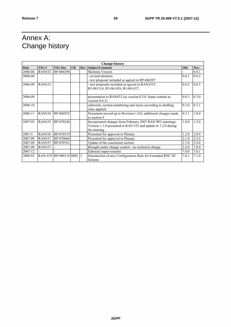
3GPP
3GPP TR 25.999 V7.0.1 (2007-12)59Release 7
Annex A: Change history
Change history Date TSG # TSG Doc. CR Rev Subject/Comment Old New 2006-06 RAN#32 RP-060296 Skeleton Version - 0.0.12006-06 - revised skeleton
- text proposal included as agreed in RP-060297 0.0.1 0.0.2
2006-09 RAN#33 - text proposals included as agreed in RAN3#53: R3-061316, R3-061426, R3-061427,
0.0.2 0.0.3
2006-09 presentation to RAN#33 (as version 0.3.0. Same content as version 0.0.3)
0.0.3 0.3.0
2006-10 editorials: section numbering and styles according to drafting rules applied.
0.3.0 0.3.1
2006-11 RAN#34 RP-060XX Document moved up to Revision 1.0.0, additional changes made to section 9
0.3.1 1.0.0
2007-03 RAN#35 RP-070246 Incorporated changes from February 2007 RAN WG meetings; Version 1.1.0 presented at RAN #35 and update to 1.2.0 during the meeting
1.0.0 1.2.0
2007-5 RAN#36 RP-070319 Presented for approval to Plenary 1.2.0 2.0.02007-09 RAN#37 RP-070666 Presented for approval to Plenary 2.1.0 2.2.02007-09 RAN#37 RP-070761 Update of the conclusion section 2.3.0 2.4.02007-09 RAN#37 - Brought under change control - no technical change 2.4.0 7.0.02007-12 - - Editorial improvements 7.0.0 7.0.12008-03 RAN #39 RP-080116 0001 1 Introduction of new Configuration Rule for Extended RNC ID
Scheme 7.0.1 7.1.0


![[Japanese]2011 dec ttc+arib](https://img.pdfslide.net/doc/110x75/556614eed8b42a7d608b491d/japanese2011-dec-ttcarib.jpg)