Embed Size (px)
Citation preview
arista.com
White Paper
Arista 7050X & 7050X2 Switch Architecture (‘A day in the life of a packet’)Arista Networks 7050 Series has become the mainstay fixed configuration 10GbE and 40GbE platform in many of the
world’s largest datacenters.
The introduction of the Arista 7050X Series extends the family with increased performance, scalability, density and
features designed for software defined networking and Universal Cloud Networks. The 7050X series adds support
for next generation features and protocols, while combining a 2 fold increase in port count, table sizes and system
forwarding capacity, without making any compromises to the system availability, reliability or functions.
The addition of the 7050X2 further expands the series, building on top of the strong foundation developed by the
7050X series. The 7050X2 introduces systems that can support single-pass VXLAN routing at full line rate speeds. This
introduction enables VXLAN routing capability concurrently with maximum interface density.
This white paper provides an overview of the switch architecture and the packet forwarding characteristics of the Arista
7050X Series.
arista.comarista.com
White Paper
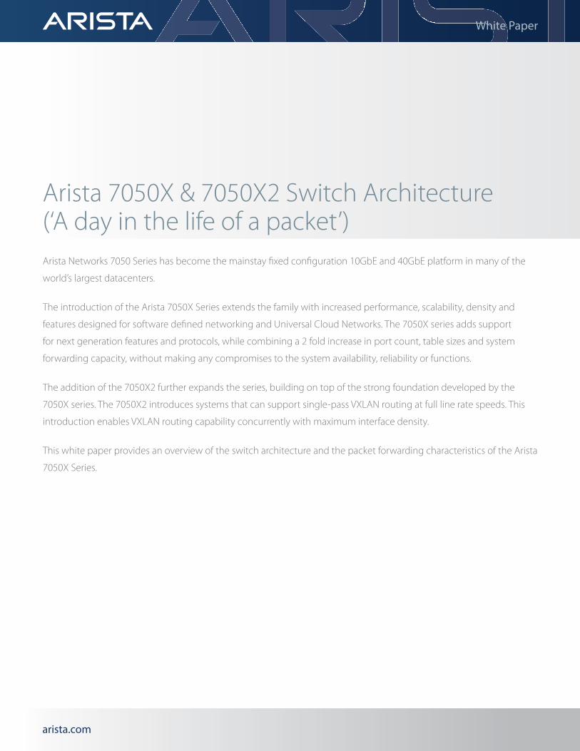
Switch OverviewThe Arista 7050X & 7050X2 series are purpose built 10GbE/40GbE datacenter switches in compact and energy efficient form factors with wirespeed layer 2 and layer 3 forwarding, combined with advanced features for software defined cloud networking.
The Arista 7050X and 7050X2 switches are a family of fixed configuration 1RU and 2RU systems, supporting a wide variety of interface form factors, platform densities and uplink connectivity options.
Designed specifically to meet the challenges of dense 10 Gigabit and 40 Gigabit Ethernet switching, the 7050X and 7050X2 series feature a flexible combination of 10GbE (MXP, SFP+, 10GBase-T or QSFP+) and 40GbE (MXP or QSFP+) interfaces in compact, low latency, power efficient form factors, supporting up to 32 x 40GbE.
The 7050X and 7050X2 Series at a GlanceIncreased adoption of 10 Gigabit Ethernet servers coupled with applications using higher bandwidth is accelerating the need for dense 10 and 40 Gigabit Ethernet switching. The 7050X & 7050X2 series supports a flexible combination of 10GbE and 40GbE in a highly compact form factor that allows customers to design flexible leaf and spine networks that accommodate both east-west traffic patterns and a requirement for low latency and power efficiency.
Table 1: Arista 7050X & 7050X2 Series Overview
7050X Models 7050QX 7050TX 7050SX 7050QX2 7050TX2 7050SX2
Characteristic 32 32S 48 64 72 72Q 96 128 64 72 72Q 96 128 32S 128 128
Switch Height (RU)
1RU 1RU 1RU 1RU 1RU 1RU 1RU 2RU 1RU 1RU 1RU 1RU 2RU 1RU 2RU 2RU
10GBASE-T -- -- 32 48 48 48 48 96 -- -- -- -- -- -- 96 --
10G SFP+ -- 4 -- -- -- -- -- -- 48 48 48 48 96 4 -- 96
40G QSFP+ 32 32 4 4 -- 6 -- 8 4 -- 6 -- 8 32 8 8
10/40G MXP -- -- -- -- 2 -- 4 -- -- 2 -- 4 -- -- -- --
Maximum Density 10GbE ports
96 96 48 64 72 72 96 96 64 72 72 96 96 96 96 96
Maximum Density 40GbE ports
32 32 4 4 6 6 12 8 4 6 6 12 8 32 8 8
Maximum HW System Throughput (Tbps)
2.56 2.56 0.96 1.28 1.44 1.44 1.92 2.56 1.28 1.44 1.44 1.92 2.56 2.56 2.56 2.56
Maximum Forwarding Rate (Bpps)
1.44 1.44 0.72 0.96 1.08 1.08 1.44 1.44 0.96 1.08 1.08 1.44 1.44 1.44 1.44 1.44
Latency 550ns 3µsec 550ns 3µsec 550ns
Packet Buffer Memory
12MB 16MB
Airflow Direction
Front-to-Back or Back-to-Front
arista.comarista.com
White Paper
Each product within the 7050X & 7050X2 series supports low-latency forwarding from just 550ns in cut-through mode. This is coupled with an extremely efficient forwarding pipeline that delivers minimal jitter. To ensure no performance hit during congestion or microbursts, the 7050X packet processor has access to a 12MB buffer, while the 7050X2 systems offer an expanded 16MB buffer. In both cases the buffer can be dynamically shared between ports that actively need it, while incorporating mechanisms to prevent buffer starvation due to elephant flows on one or more ports.
All models within the 7050X & 7050X2 family share common system architecture built upon the same system on chip (SOC) silicon. Varying only in interface type and quantity provided, all models share a common set of software and hardware features, and key capabilities for high availability and reversible airflow options.
In addition to the industry standard 10GBASE-T RJ45, 1/10G SFP+ and 10/40G QSFP+ interfaces, several models within the 7050X family offer support for the innovative Arista Multi-speed ports (MXP). Each MXP port delivers 120Gbps of useable bandwidth, which can be presented in combinations of 10Gb or 40Gb. A single MXP port enables up to 12 10Gbps interfaces, 3 40Gbps interfaces or a combination of the two. The use of the MXP/MTP fiber breakout cables enables a higher total of network ports which in turn connects to a larger number of hosts without the need to increase the number of physical interfaces on the switch front panel, and as a result avoids the need to expand the form factor into additional rack units. Multi-speed (MXP) ports achieve the additional density through the use of embedded optics built directly into the switch allowing for a single high-density interface to concentrate multiple ports, and in turn removing the requirement to purchase external transceivers.
With typical power consumption of under 5 watts per 40GbE port the 7050X & 7050X2 Series provide industry leading power efficiency coupled with power supplies that are rated at 94% efficiency at typical loads, which is equivalent to platinum level. All 7050X & 7050X2 models offer a choice of airflow direction to support deployment in either hot aisle / cold aisle containment environments, as the top of rack switch, middle and end of row designs or at the network spine layer. All models support an optional built-in SSD that enables advanced capabilities; for example long term logging, data capture or for any services that run directly on the switch.
Built on top of the same industry defining EOS image that runs on the entire Arista product portfolio, the 7050X & 7050X2 Series delivers advanced features for big data, cloud, SDN, virtualized and traditional enterprise network designs.
7050X & 7050X2 Packet Processor ConfigurationsAt a high level the 7050X & 7050X2 series are both classified as “single chip” systems. A single chip switch refers to a System on a Chip (SoC) solution, where all hardware resources (such as packet buffer memory and forwarding tables) are embedded directly onto the chip, enabling all hardware forwarding actions to be managed and executed from a single piece of switching silicon. The converged approach afforded by SoC designs enables the creation of systems with significantly lower power consumption and higher MTBFs.
Advances in switching silicon technology enable the 7050X & 7050X2 Series to significantly increase the number of line rate interfaces delivered on a single chip, while still maintaining high throughput and exceptional performance.
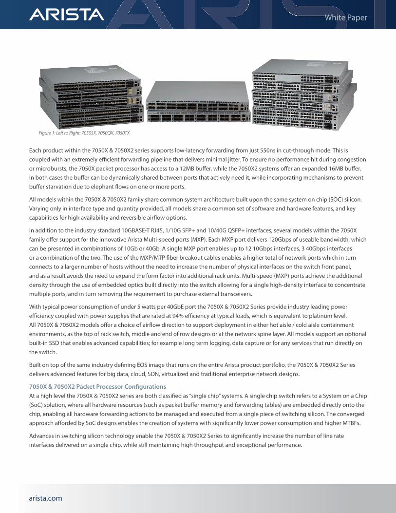
Figure 1: Left to Right: 7050SX, 7050QX, 7050TX
arista.comarista.com
White Paper
7050X & 7050X2 ArchitectureAll stages of the forwarding pipeline are performed entirely in the hardware/data plane. The forwarding pipeline is a closed system integrated on the packet processor (PP) of each SoC. The packet processors are capable of providing both the ingress and egress forwarding pipeline stages for packets that arrive on or are destined to ports located on that packet processor.
All 7050X & 7050X2 series platforms offer front facing management and console connectivity for ease of access. The 7050X also provides a front facing USB slot that can be used for a variety of purposes including onboard memory expansion, disaster recovery and ease of upgrade/maintenance.
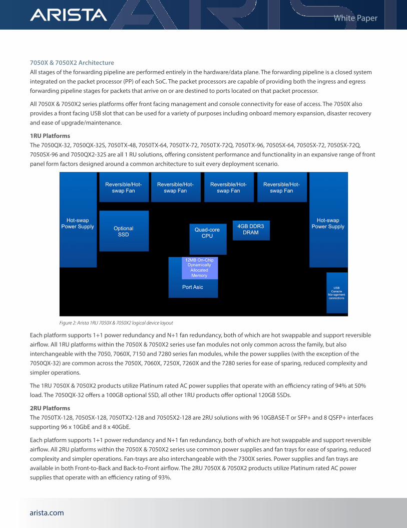
1RU PlatformsThe 7050QX-32, 7050QX-32S, 7050TX-48, 7050TX-64, 7050TX-72, 7050TX-72Q, 7050TX-96, 7050SX-64, 7050SX-72, 7050SX-72Q, 7050SX-96 and 7050QX2-32S are all 1 RU solutions, offering consistent performance and functionality in an expansive range of front panel form factors designed around a common architecture to suit every deployment scenario.
Each platform supports 1+1 power redundancy and N+1 fan redundancy, both of which are hot swappable and support reversible airflow. All 1RU platforms within the 7050X & 7050X2 series use fan modules not only common across the family, but also interchangeable with the 7050, 7060X, 7150 and 7280 series fan modules, while the power supplies (with the exception of the 7050QX-32) are common across the 7050X, 7060X, 7250X, 7260X and the 7280 series for ease of sparing, reduced complexity and simpler operations.
The 1RU 7050X & 7050X2 products utilize Platinum rated AC power supplies that operate with an efficiency rating of 94% at 50% load. The 7050QX-32 offers a 100GB optional SSD, all other 1RU products offer optional 120GB SSDs.
2RU PlatformsThe 7050TX-128, 7050SX-128, 7050TX2-128 and 7050SX2-128 are 2RU solutions with 96 10GBASE-T or SFP+ and 8 QSFP+ interfaces supporting 96 x 10GbE and 8 x 40GbE.
Each platform supports 1+1 power redundancy and N+1 fan redundancy, both of which are hot swappable and support reversible airflow. All 2RU platforms within the 7050X & 7050X2 series use common power supplies and fan trays for ease of sparing, reduced complexity and simpler operations. Fan-trays are also interchangeable with the 7300X series. Power supplies and fan trays are available in both Front-to-Back and Back-to-Front airflow. The 2RU 7050X & 7050X2 products utilize Platinum rated AC power supplies that operate with an efficiency rating of 93%.
Figure 2: Arista 1RU 7050X & 7050X2 logical device layout
arista.comarista.com
White Paper
7050X Forwarding NodesThe Arista 7050X Series support a flexible set of configurable forwarding modes. Each mode results in slightly different behavior for traffic to and from interfaces at the same speed, whether 40GbE QSFP+ ports can be expanded into multiple 10GbE ports, and the availability of internal bandwidth for recirculation. The default mode for the larger 7050X providing more than 96 lanes of 10GbE to front panel interfaces (either via SFP+, 10GBASE-T or QSFP+) is performance mode (referred to as over subscribed mode in the CLI). This allows all lanes/interfaces to operate in parallel, by slightly oversubscribing the core bandwidth of the packet processor. All devices providing 96 or fewer lanes of 10GbE do not require performance mode to support all front panel interfaces concurrently, by default such devices operate in 10GbE latency mode (referred to as line rate mode via the CLI). The table below details which modes are available.
The 7050QX-32, 7050QX-32S, 7050TX-128 and 7050SX-128 switches support three forwarding modes; Performance mode, 10GbE latency mode and Recirculation mode.
Performance mode is ideal for deployments where network scale is the primary objective. This mode enables all front panel interfaces in parallel. Packets switched between interfaces both running at 40GbE are cut-through, while switching between interfaces at 10GbE or mixed speeds (40GbE to 10GbE or vice versa) operates on a store-and-forward basis. In performance mode the rightmost eight QSFP+ interfaces operate exclusively as 40GbE. All other QSFP+ interfaces can be used as native 40GbE or broken out into four 10GbE interfaces through the use of suitable transceivers and splitter cables, while all 10GBASE-T/SFP+ ports can be used as 100M/1G/10GbE interfaces. This flexibility allows the configuration of up to 32 40GbE interfaces on the 7050QX-32/32S or up to 96 1/10GbE & 8 40GbE interfaces on all four platforms.
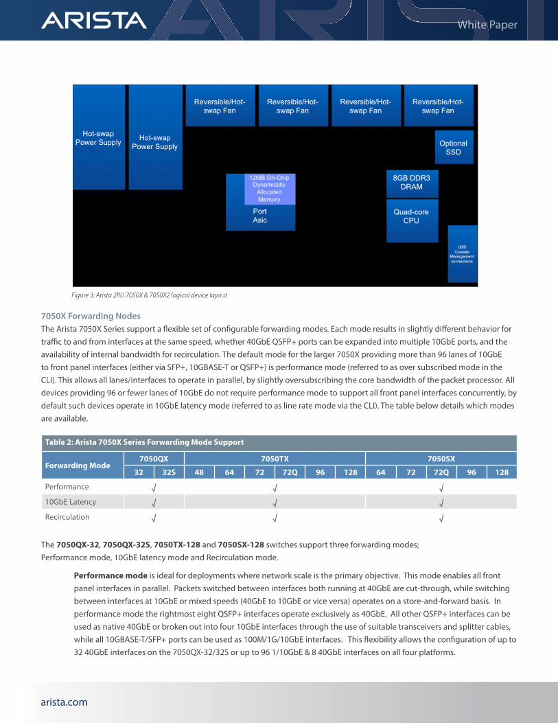
Figure 3: Arista 2RU 7050X & 7050X2 logical device layout
Table 2: Arista 7050X Series Forwarding Mode Support
Forwarding Mode7050QX 7050TX 7050SX
32 32S 48 64 72 72Q 96 128 64 72 72Q 96 128
Performance √ √ √10GbE Latency √ √ √Recirculation √ √ √
arista.comarista.com
White Paper
10GbE latency mode is suited to deployments where 10GbE latency is a primary concern. Enabling 10GbE latency mode will allow switching between interfaces at the same speeds (10GbE-10GbE and 40GbE-40GbE) to take place in a cut-through mode. In 10GbE latency mode the rightmost eight QSFP+ interfaces are disabled, however any remaining QSFP+ interfaces can be used as either native 40GbE or broken out to four 10GbE interfaces. Allowing up to 24 40GbE interfaces on the 7050QX-32/32S or up to 96 10GbE interfaces on all four platforms.
Recirculation mode is designed for deployments using a complex interaction of features that require multiple passes of the forwarding pipeline, such as L3 VXLAN based routing. Recirculation mode creates an array of internal connections to enable high bandwidth packet recirculation without the need for any external or loopback cables. In order to make the internal bandwidth available for recirculation the rightmost 8 QSFP+ interfaces are disabled. All remaining QSFP+ interfaces can be used as native 40GbE or broken out to four 10GbE interfaces, all SFP+/Base-T interfaces function as 1/10GbE. While packet switching between interfaces running at 40GbE the switching behavior is cut-through forwarding, switching between two interfaces at 10GbE or mixed speeds (40GbE to 10GbE or vice versa) operates in a store-and-forward mode.
The 7050TX-48, 7050TX-64, 7050TX-72, 7050TX-72Q, 7050TX-96, 7050SX-64, 7050SX-72, 7050SX-72Q and the 7050SX-96 devices support the same three forwarding modes, however each has slightly different implications. All of the above devices default to low-latency mode, as performance mode is not required to support all front panel interfaces concurrently, performance mode is still supported, and useful in one specific situation.
10GbE latency mode is suited to deployments where 10GbE latency is a primary concern. Enabling 10GbE latency mode will allow switching between interfaces at the same speeds (10GbE-10GbE and 40GbE-40GbE) to take place in a cut-through mode. In 10GbE latency mode all QSFP+ interfaces can be used as native 40GbE or broken out to four 10GbE interfaces, while all SFP+/Base-T interfaces function as 1/10GbE. On the listed platforms 10GbE latency mode does not disable any external interfaces.
Performance mode is not required to concurrently support all front panel interfaces, however Performance mode does allow the user to reclaim unused internal bandwidth and reallocate that to recirculation mode, providing an additional 8 x 40GbE of internal loopback interfaces.
Recirculation mode is designed for deployments using a complex interaction of features that require multiple passes of the forwarding pipeline, such as L3 VXLAN based routing. Recirculation mode creates an array of internal connections to enable high bandwidth packet recirculation without the need for any external or loopback cables. On the above platforms recirculation mode does not require the disabling of any external interfaces. If the switch is configured in 10GbE latency mode 8 of the internal 40GbE interfaces will be disabled and unavailable for recirculation. On the above platforms, all QSFP+ interfaces can be used as native 40GbE or broken out to four 10GbE interfaces, all SFP+/Base-T interfaces function as 10GbE. While packet switching between interfaces running at 40GbE the switching behavior is cut-through, switching between two interfaces at 10GbE or mixed speeds (40GbE to 10GbE or vice versa) operates on a store-and-forward basis. Recirculation mode can be supported regardless of if the switch is configured in 10G Latency (linerate) mode or Performance (oversubscribed mode).
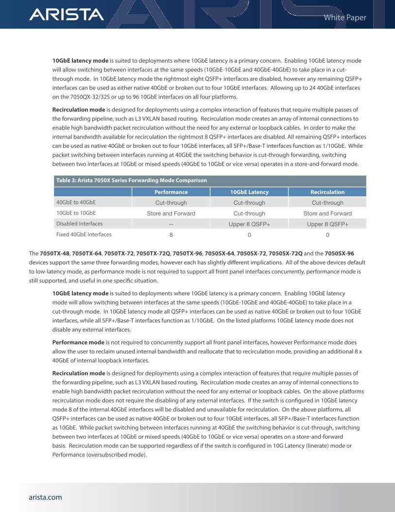
Table 3: Arista 7050X Series Forwarding Mode Comparison
Performance 10GbE Latency Recirculation
40GbE to 40GbE Cut-through Cut-through Cut-through10GbE to 10GbE Store and Forward Cut-through Store and ForwardDisabled Interfaces -- Upper 8 QSFP+ Upper 8 QSFP+Fixed 40GbE Interfaces 8 0 0
arista.comarista.com
White Paper
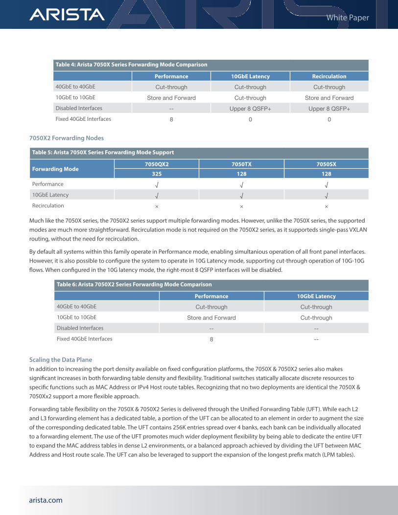
Table 4: Arista 7050X Series Forwarding Mode Comparison
Performance 10GbE Latency Recirculation
40GbE to 40GbE Cut-through Cut-through Cut-through10GbE to 10GbE Store and Forward Cut-through Store and ForwardDisabled Interfaces -- Upper 8 QSFP+ Upper 8 QSFP+Fixed 40GbE Interfaces 8 0 0
7050X2 Forwarding Nodes
Table 5: Arista 7050X Series Forwarding Mode Support
Forwarding Mode7050QX2 7050TX 7050SX
32S 128 128
Performance √ √ √10GbE Latency √ √ √Recirculation × × ×
Much like the 7050X series, the 7050X2 series support multiple forwarding modes. However, unlike the 7050X series, the supported modes are much more straightforward. Recirculation mode is not required on the 7050X2 series, as it supporteds single-pass VXLAN routing, without the need for recirculation.
By default all systems within this family operate in Performance mode, enabling simultanious operation of all front panel interfaces. However, it is also possible to configure the system to operate in 10G Latency mode, supporting cut-through operation of 10G-10G flows. When configured in the 10G latency mode, the right-most 8 QSFP interfaces will be disabled.
Scaling the Data PlaneIn addition to increasing the port density available on fixed configuration platforms, the 7050X & 7050X2 series also makes significant increases in both forwarding table density and flexibility. Traditional switches statically allocate discrete resources to specific functions such as MAC Address or IPv4 Host route tables. Recognizing that no two deployments are identical the 7050X & 7050Xx2 support a more flexible approach.
Forwarding table flexibility on the 7050X & 7050X2 Series is delivered through the Unified Forwarding Table (UFT). While each L2 and L3 forwarding element has a dedicated table, a portion of the UFT can be allocated to an element in order to augment the size of the corresponding dedicated table. The UFT contains 256K entries spread over 4 banks, each bank can be individually allocated to a forwarding element. The use of the UFT promotes much wider deployment flexibility by being able to dedicate the entire UFT to expand the MAC address tables in dense L2 environments, or a balanced approach achieved by dividing the UFT between MAC Address and Host route scale. The UFT can also be leveraged to support the expansion of the longest prefix match (LPM tables).
Table 6: Arista 7050X2 Series Forwarding Mode Comparison
Performance 10GbE Latency
40GbE to 40GbE Cut-through Cut-through10GbE to 10GbE Store and Forward Cut-throughDisabled Interfaces -- --Fixed 40GbE Interfaces 8 --
arista.comarista.com
White Paper
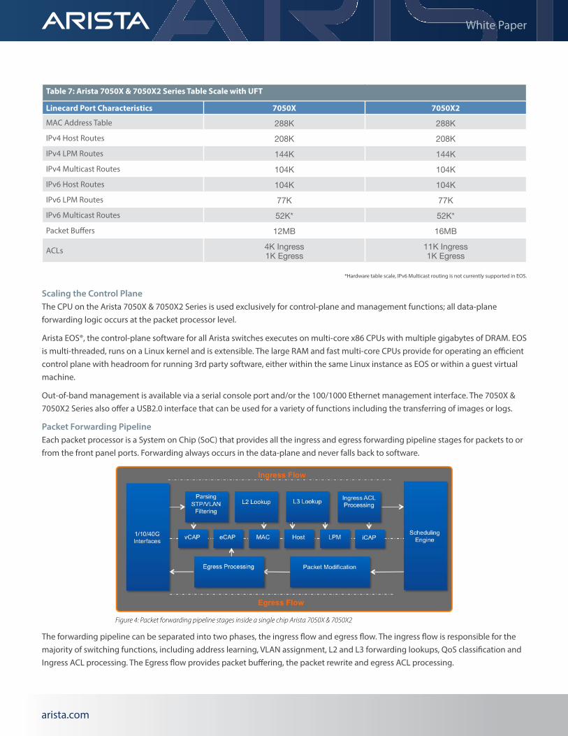
*Hardware table scale, IPv6 Multicast routing is not currently supported in EOS.
Scaling the Control PlaneThe CPU on the Arista 7050X & 7050X2 Series is used exclusively for control-plane and management functions; all data-plane forwarding logic occurs at the packet processor level.
Arista EOS®, the control-plane software for all Arista switches executes on multi-core x86 CPUs with multiple gigabytes of DRAM. EOS is multi-threaded, runs on a Linux kernel and is extensible. The large RAM and fast multi-core CPUs provide for operating an efficient control plane with headroom for running 3rd party software, either within the same Linux instance as EOS or within a guest virtual machine.
Out-of-band management is available via a serial console port and/or the 100/1000 Ethernet management interface. The 7050X & 7050X2 Series also offer a USB2.0 interface that can be used for a variety of functions including the transferring of images or logs.
Packet Forwarding PipelineEach packet processor is a System on Chip (SoC) that provides all the ingress and egress forwarding pipeline stages for packets to or from the front panel ports. Forwarding always occurs in the data-plane and never falls back to software.
The forwarding pipeline can be separated into two phases, the ingress flow and egress flow. The ingress flow is responsible for the majority of switching functions, including address learning, VLAN assignment, L2 and L3 forwarding lookups, QoS classification and Ingress ACL processing. The Egress flow provides packet buffering, the packet rewrite and egress ACL processing.
Table 7: Arista 7050X & 7050X2 Series Table Scale with UFT
Linecard Port Characteristics 7050X 7050X2
MAC Address Table 288K 288KIPv4 Host Routes 208K 208KIPv4 LPM Routes 144K 144KIPv4 Multicast Routes 104K 104KIPv6 Host Routes 104K 104KIPv6 LPM Routes 77K 77KIPv6 Multicast Routes 52K* 52K*Packet Buffers 12MB 16MB
ACLs 4K Ingress 1K Egress
11K Ingress 1K Egress
Figure 4: Packet forwarding pipeline stages inside a single chip Arista 7050X & 7050X2
arista.comarista.com
White Paper
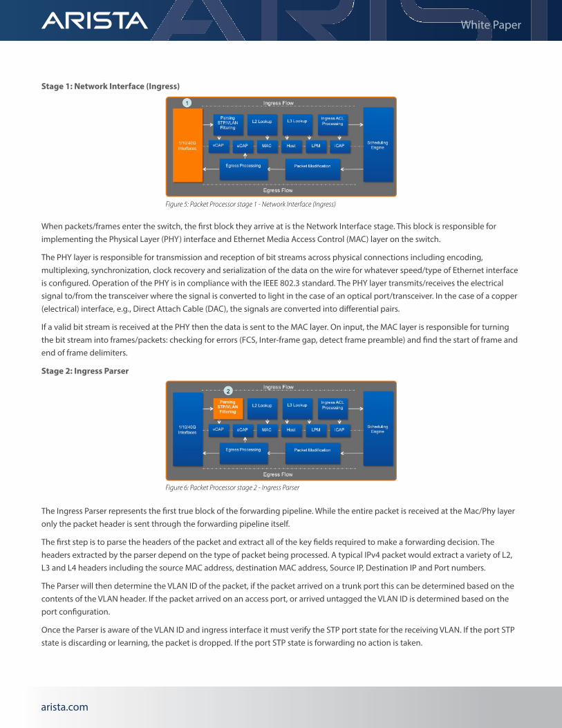
Stage 1: Network Interface (Ingress)
When packets/frames enter the switch, the first block they arrive at is the Network Interface stage. This block is responsible for implementing the Physical Layer (PHY) interface and Ethernet Media Access Control (MAC) layer on the switch.
The PHY layer is responsible for transmission and reception of bit streams across physical connections including encoding, multiplexing, synchronization, clock recovery and serialization of the data on the wire for whatever speed/type of Ethernet interface is configured. Operation of the PHY is in compliance with the IEEE 802.3 standard. The PHY layer transmits/receives the electrical signal to/from the transceiver where the signal is converted to light in the case of an optical port/transceiver. In the case of a copper (electrical) interface, e.g., Direct Attach Cable (DAC), the signals are converted into differential pairs.
If a valid bit stream is received at the PHY then the data is sent to the MAC layer. On input, the MAC layer is responsible for turning the bit stream into frames/packets: checking for errors (FCS, Inter-frame gap, detect frame preamble) and find the start of frame and end of frame delimiters.
Stage 2: Ingress Parser
The Ingress Parser represents the first true block of the forwarding pipeline. While the entire packet is received at the Mac/Phy layer only the packet header is sent through the forwarding pipeline itself.
The first step is to parse the headers of the packet and extract all of the key fields required to make a forwarding decision. The headers extracted by the parser depend on the type of packet being processed. A typical IPv4 packet would extract a variety of L2, L3 and L4 headers including the source MAC address, destination MAC address, Source IP, Destination IP and Port numbers.
The Parser will then determine the VLAN ID of the packet, if the packet arrived on a trunk port this can be determined based on the contents of the VLAN header. If the packet arrived on an access port, or arrived untagged the VLAN ID is determined based on the port configuration.
Once the Parser is aware of the VLAN ID and ingress interface it must verify the STP port state for the receiving VLAN. If the port STP state is discarding or learning, the packet is dropped. If the port STP state is forwarding no action is taken.
Figure 5: Packet Processor stage 1 - Network Interface (Ingress)
Figure 6: Packet Processor stage 2 - Ingress Parser
arista.comarista.com
White Paper
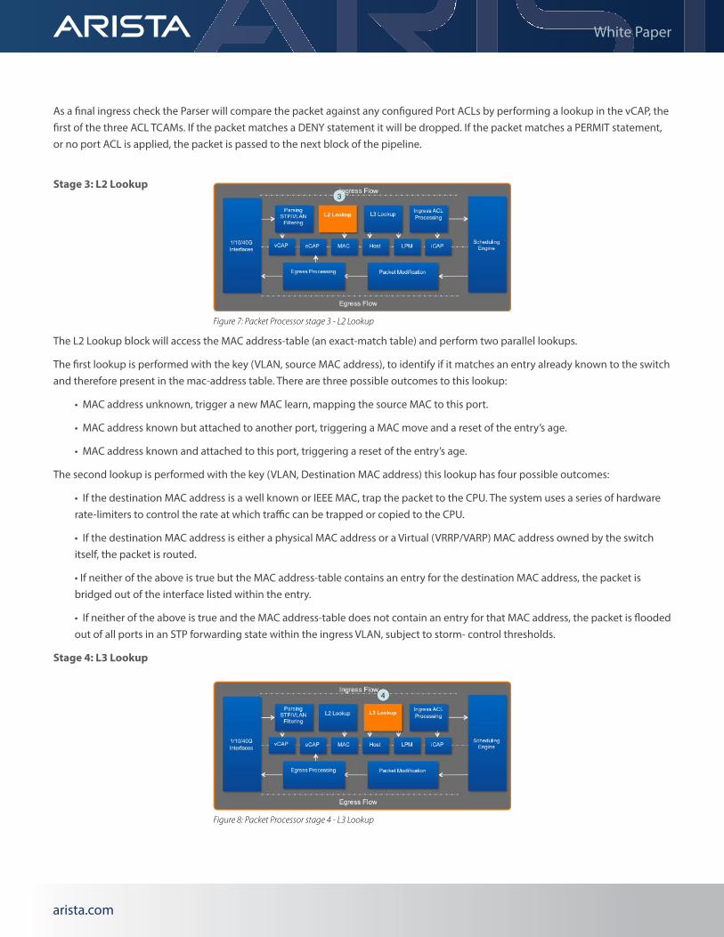
As a final ingress check the Parser will compare the packet against any configured Port ACLs by performing a lookup in the vCAP, the first of the three ACL TCAMs. If the packet matches a DENY statement it will be dropped. If the packet matches a PERMIT statement, or no port ACL is applied, the packet is passed to the next block of the pipeline.
Stage 3: L2 Lookup
The L2 Lookup block will access the MAC address-table (an exact-match table) and perform two parallel lookups.
The first lookup is performed with the key (VLAN, source MAC address), to identify if it matches an entry already known to the switch and therefore present in the mac-address table. There are three possible outcomes to this lookup:
• MAC address unknown, trigger a new MAC learn, mapping the source MAC to this port.
• MAC address known but attached to another port, triggering a MAC move and a reset of the entry’s age.
• MAC address known and attached to this port, triggering a reset of the entry’s age.
The second lookup is performed with the key (VLAN, Destination MAC address) this lookup has four possible outcomes:
• If the destination MAC address is a well known or IEEE MAC, trap the packet to the CPU. The system uses a series of hardware rate-limiters to control the rate at which traffic can be trapped or copied to the CPU.
• If the destination MAC address is either a physical MAC address or a Virtual (VRRP/VARP) MAC address owned by the switch itself, the packet is routed.
• If neither of the above is true but the MAC address-table contains an entry for the destination MAC address, the packet is bridged out of the interface listed within the entry.
• If neither of the above is true and the MAC address-table does not contain an entry for that MAC address, the packet is flooded out of all ports in an STP forwarding state within the ingress VLAN, subject to storm- control thresholds.
Stage 4: L3 Lookup
Figure 7: Packet Processor stage 3 - L2 Lookup
Figure 8: Packet Processor stage 4 - L3 Lookup
arista.comarista.com
White Paper
The L3 Lookup stage performs sequential accesses into two distinct tables, each access includes up to two lookups. The first table is an exact-match table which contains /32 v4 and /128 v6 host routes. The second table is a longest-prefix match (LPM) table which contains all v4 routes and v6 routes shorter than /32 and /128 lengths respectively.
The first lookup into both the host route and LPM tables is based on the key (VRF, Source IP Address), this lookup is designed to verify that the packet was received on the correct interface (the best interface towards the source of the packet), if received on any other interface the packet may be dropped depending on user configuration. This lookup takes place only if uRPF is enabled.
The second lookup takes place initially in the host route table; the lookup is based on the key (VRF, Destination IP address) the purpose is to attempt to find an exact match for the destination IP address. This is typically seen if the destination is a host in a directly connected subnet. If an exact match is found in the host route table the result provides a pointer to an egress physical port, L3 interface and packet rewrite data.
If there is no match for the lookup in the host table, another lookup with an identical key is performed in the LPM table to find the best or longest prefix-match, with a default route being used as a last resort. This lookup has three possible outcomes:
• If there is no match, including no default route, then the packet is dropped.
• If there is a match in the LPM and that match is a directly connected subnet, but there was no entry for the destination in the host route table, the packet is punted to the CPU to generate an ARP request.
• If there is a match in the LPM table, and it is not a directly connected subnet it will resolve to a next-hop entry which will be located in the Host Route table. This entry provides an egress physical port, L3 interface and packet rewrite data.
The logic for multicast traffic is virtually identical, with multicast routes occupying the same tables as the unicast routes. However instead of providing egress port and rewrite information, the adjacency points to a Multicast ID. The Multicast ID indexes to an entry in the multicast expansion table to provide a list of output interfaces.
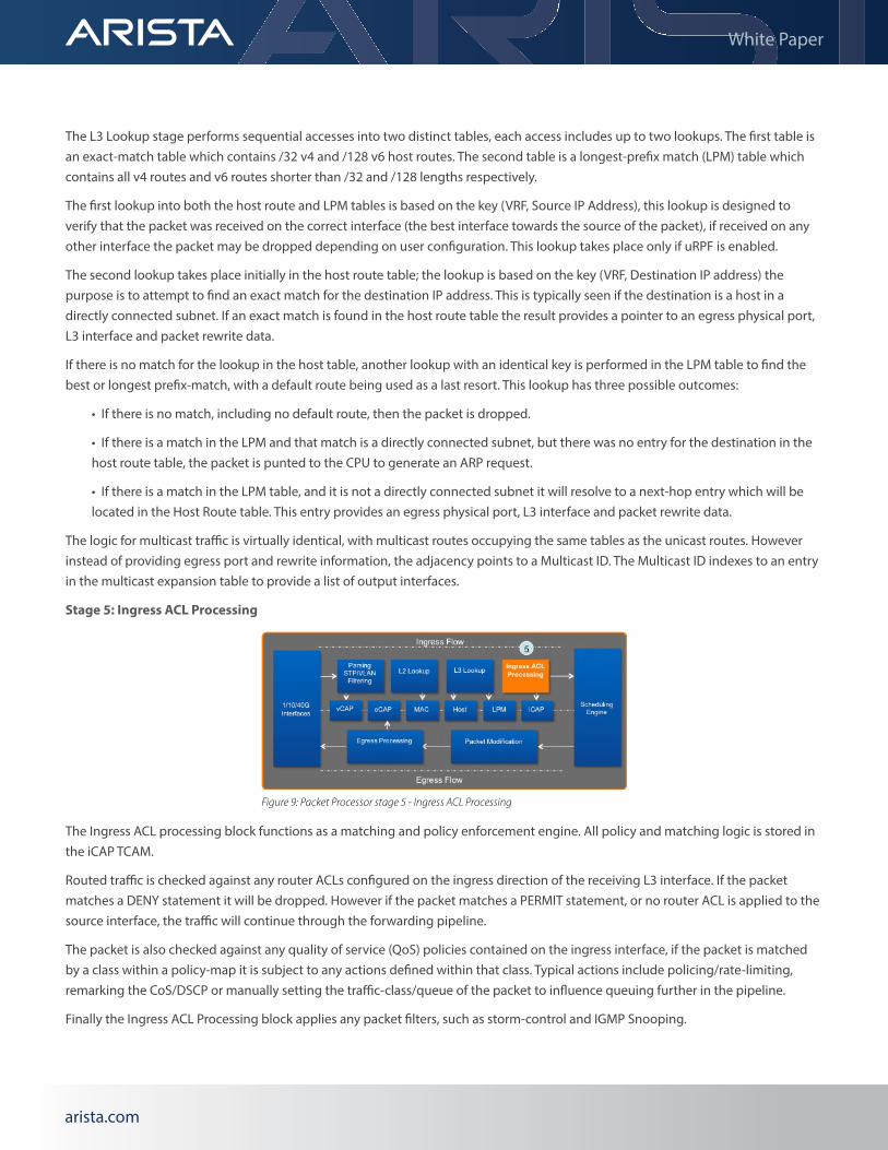
Stage 5: Ingress ACL Processing
The Ingress ACL processing block functions as a matching and policy enforcement engine. All policy and matching logic is stored in the iCAP TCAM.
Routed traffic is checked against any router ACLs configured on the ingress direction of the receiving L3 interface. If the packet matches a DENY statement it will be dropped. However if the packet matches a PERMIT statement, or no router ACL is applied to the source interface, the traffic will continue through the forwarding pipeline.
The packet is also checked against any quality of service (QoS) policies contained on the ingress interface, if the packet is matched by a class within a policy-map it is subject to any actions defined within that class. Typical actions include policing/rate-limiting, remarking the CoS/DSCP or manually setting the traffic-class/queue of the packet to influence queuing further in the pipeline.
Finally the Ingress ACL Processing block applies any packet filters, such as storm-control and IGMP Snooping.
Figure 9: Packet Processor stage 5 - Ingress ACL Processing
arista.comarista.com
White Paper
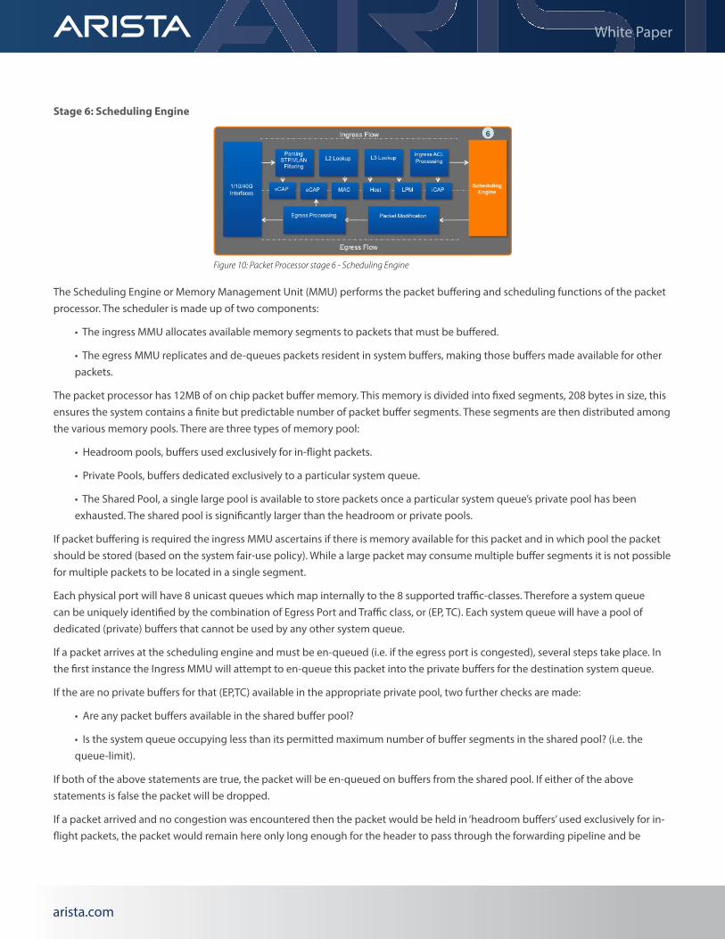
Stage 6: Scheduling Engine
The Scheduling Engine or Memory Management Unit (MMU) performs the packet buffering and scheduling functions of the packet processor. The scheduler is made up of two components:
• The ingress MMU allocates available memory segments to packets that must be buffered.
• The egress MMU replicates and de-queues packets resident in system buffers, making those buffers made available for other packets.
The packet processor has 12MB of on chip packet buffer memory. This memory is divided into fixed segments, 208 bytes in size, this ensures the system contains a finite but predictable number of packet buffer segments. These segments are then distributed among the various memory pools. There are three types of memory pool:
• Headroom pools, buffers used exclusively for in-flight packets.
• Private Pools, buffers dedicated exclusively to a particular system queue.
• The Shared Pool, a single large pool is available to store packets once a particular system queue’s private pool has been exhausted. The shared pool is significantly larger than the headroom or private pools.
If packet buffering is required the ingress MMU ascertains if there is memory available for this packet and in which pool the packet should be stored (based on the system fair-use policy). While a large packet may consume multiple buffer segments it is not possible for multiple packets to be located in a single segment.
Each physical port will have 8 unicast queues which map internally to the 8 supported traffic-classes. Therefore a system queue can be uniquely identified by the combination of Egress Port and Traffic class, or (EP, TC). Each system queue will have a pool of dedicated (private) buffers that cannot be used by any other system queue.
If a packet arrives at the scheduling engine and must be en-queued (i.e. if the egress port is congested), several steps take place. In the first instance the Ingress MMU will attempt to en-queue this packet into the private buffers for the destination system queue.
If the are no private buffers for that (EP,TC) available in the appropriate private pool, two further checks are made:
• Are any packet buffers available in the shared buffer pool?
• Is the system queue occupying less than its permitted maximum number of buffer segments in the shared pool? (i.e. the queue-limit).
If both of the above statements are true, the packet will be en-queued on buffers from the shared pool. If either of the above statements is false the packet will be dropped.
If a packet arrived and no congestion was encountered then the packet would be held in ‘headroom buffers’ used exclusively for in-flight packets, the packet would remain here only long enough for the header to pass through the forwarding pipeline and be
Figure 10: Packet Processor stage 6 - Scheduling Engine
arista.comarista.com
White Paper
serialized out of the egress interface.
Once a system queue contains 1 or more segments the egress MMU will attempt to de-queue these segments. The egress MMU will attempt to forward packets out of an Egress Port on a per Traffic Class basis. The rate at which this occurs is based on the queuing configuration and any configured egress packet shaping. By default the MMU will be configured with hierarchical strict priority queues, this ensures packets in traffic-class 5 are processed only when the higher priority classes 6 and 7 are empty, while packets in traffic-class 4 are processed only when classes 5, 6 and 7 are empty etc.
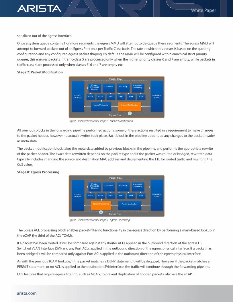
Stage 7: Packet Modification
All previous blocks in the forwarding pipeline performed actions, some of these actions resulted in a requirement to make changes to the packet header, however no actual rewrites took place. Each block in the pipeline appended any changes to the packet header as meta-data.
The packet modification block takes the meta-data added by previous blocks in the pipeline, and performs the appropriate rewrite of the packet header. The exact data rewritten depends on the packet type and if the packet was routed or bridged, rewritten data typically includes changing the source and destination MAC address and decrementing the TTL for routed traffic and rewriting the CoS value.
Stage 8: Egress Processing
The Egress ACL processing block enables packet-filtering functionality in the egress direction by performing a mask-based lookup in the eCAP, the third of the ACL TCAMs.
If a packet has been routed, it will be compared against any Router ACLs applied in the outbound direction of the egress L3 Switched VLAN Interface (SVI) and any Port ACLs applied in the outbound direction of the egress physical interface. If a packet has been bridged it will be compared only against Port ACLs applied in the outbound direction of the egress physical interface.
As with the previous TCAM lookups, if the packet matches a DENY statement it will be dropped. However if the packet matches a PERMIT statement, or no ACL is applied to the destination SVI/interface, the traffic will continue through the forwarding pipeline.
EOS features that require egress filtering, such as MLAG, to prevent duplication of flooded packets, also use the eCAP .
Figure 11: Packet Processor stage 7 - Packet Modification
Figure 12: Packet Processor stage 8 - Egress Processing
arista.comarista.com
White Paper
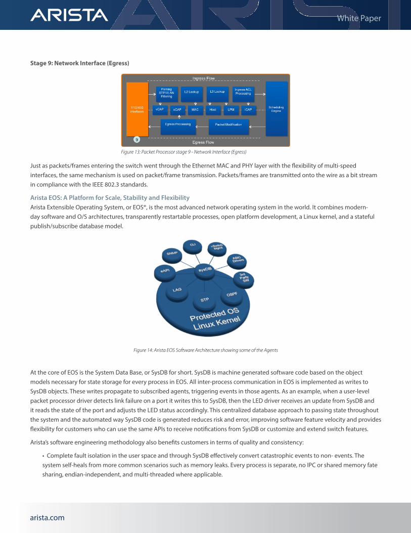
Stage 9: Network Interface (Egress)
Just as packets/frames entering the switch went through the Ethernet MAC and PHY layer with the flexibility of multi-speed interfaces, the same mechanism is used on packet/frame transmission. Packets/frames are transmitted onto the wire as a bit stream in compliance with the IEEE 802.3 standards.
Arista EOS: A Platform for Scale, Stability and FlexibilityArista Extensible Operating System, or EOS®, is the most advanced network operating system in the world. It combines modern-day software and O/S architectures, transparently restartable processes, open platform development, a Linux kernel, and a stateful publish/subscribe database model.
At the core of EOS is the System Data Base, or SysDB for short. SysDB is machine generated software code based on the object models necessary for state storage for every process in EOS. All inter-process communication in EOS is implemented as writes to SysDB objects. These writes propagate to subscribed agents, triggering events in those agents. As an example, when a user-level packet processor driver detects link failure on a port it writes this to SysDB, then the LED driver receives an update from SysDB and it reads the state of the port and adjusts the LED status accordingly. This centralized database approach to passing state throughout the system and the automated way SysDB code is generated reduces risk and error, improving software feature velocity and provides flexibility for customers who can use the same APIs to receive notifications from SysDB or customize and extend switch features.
Arista’s software engineering methodology also benefits customers in terms of quality and consistency:
• Complete fault isolation in the user space and through SysDB effectively convert catastrophic events to non- events. The system self-heals from more common scenarios such as memory leaks. Every process is separate, no IPC or shared memory fate sharing, endian-independent, and multi-threaded where applicable.
Figure 14: Arista EOS Software Architecture showing some of the Agents
Figure 13: Packet Processor stage 9 - Network Interface (Egress)
arista.comarista.comarista.com
Santa Clara—Corporate Headquarters5453 Great America Parkway, Santa Clara, CA 95054
Phone: +1-408-547-5500 Fax: +1-408-538-8920 Email: [email protected]
White Paper
Ireland—International Headquarters 3130 Atlantic Avenue Westpark Business Campus Shannon, Co. Clare Ireland
Vancouver—R&D Office 9200 Glenlyon Pkwy, Unit 300 Burnaby, British Columbia Canada V5J 5J8
San Francisco—R&D and Sales Office 1390 Market Street, Suite 800 San Francisco, CA 94102
India—R&D Office Global Tech Park, Tower A & B, 11th Floor Marathahalli Outer Ring Road Devarabeesanahalli Village, Varthur Hobli Bangalore, India 560103
Singapore—APAC Administrative Office 9 Temasek Boulevard #29-01, Suntec Tower Two Singapore 038989
Nashua—R&D Office 10 Tara Boulevard Nashua, NH 03062
Copyright © 2017 Arista Networks, Inc. All rights reserved. CloudVision, and EOS are registered trademarks and Arista Networks is a trademark of Arista Networks, Inc. All other company names are trademarks of their respective holders. Information in this document is subject to change without notice. Certain features may not yet be available. Arista Networks, Inc. assumes no responsibility for any errors that may appear in this document. July 01, 2018 02-0013-03
• No manual software testing. All automated tests run 24x7 and with the operating system running in emulators and on hardware Arista scales protocol and unit testing cost effectively.
• Keep a single system binary across all platforms. This improves the testing depth on each platform, improves time-to-market, and keeps feature and bug compatibility across all platforms.
EOS, and at its core SysDB, provide a development framework that enables the core concept - Extensibility. An open foundation, and best-in-class software development models deliver feature velocity, improved uptime, easier maintenance, and a choice in tools and options.
ConclusionThe 7050X & 7050X2 Series combined with the Arista leaf-spine design methodology and the Arista 7000 Family provides flexible design solutions for network architects looking to deliver market-leading performance driven networks, which scale from several hundred hosts all the way up several hundred thousand hosts. The vast range of densities, form factors and uplink connectivity options available within the 7050X series ensures that Network architects can build such a solution upon the device that explicitly fulfills the functional requirements of the project, rather than make design compromises with limited traditional form factors.
The performance focused 7050X2 Series delivers up to 32 x 40GbE or 96 x 10GbE and 8 x 40GbE ports designed specifically to operate in a real world deployment. With up to 2.56Tbps or 1.44Bpps of forwarding capacity, the 7050X Series provides the port density, table scale, feature set and forwarding capacity essential in today’s datacenter environments. The 7050X2 augments the 7050X series to provide the same level of flexible functionality, even in demanding environments that require high-density switches and line rate VXLAN routing.
All Arista products including the 7050X & 7050X2 Series run the same Arista EOS software binary image, simplifying network administration with a single standard across all switches. Arista EOS is a modular switch operating system with a unique state sharing architecture that cleanly separates switch state from protocol processing and application logic. Built on top of a standard Linux kernel, all EOS processes run in their own protected memory space and exchange state through an in-memory database. This multi-process state sharing architecture provides the foundation for in-service-software updates and self-healing resiliency.
Combining the broad functionality with the diverse form factors make the Arista 7050X & 7050X2 Series ideal for building reliable, low latency, cost effective and highly scalable datacenter networks, regardless of the deployment size and scale.


![EOS APIs - Meetupfiles.meetup.com/3747522/EOS.pdf · 3 My switch is a Linux server! Arista#bash Arista Networks EOS shell [admin@localhost ~]$ uname -rpo 2.6.32.28.Ar-856351.EOS4102](https://img.pdfslide.net/doc/110x75/5f6a63fdd38df34c32792809/eos-apis-3-my-switch-is-a-linux-server-aristabash-arista-networks-eos-shell.jpg)