Embed Size (px)
Citation preview

400
Installation InstructionsType C BoilersG.C.N: 47-116-11
LEAVE THESE INSTRUCTIONSWITH THE END USER
Country of destination: GB
2 400
TABLE OF CONTENTS 1. GENERAL INFORMATION
1.1 General Instructions1.2 Overall View
2. INSTALLATION
2.1 Reference Standards2.2 Siting the Appliance2.3 Overall Dimensions2.4 Clearances2.5 Mounting the Appliance2.6 Electrical Connection2.7 Gas Connection2.8 Water Connections2.9 Flue Connection2.10 Room Thermostat Connection2.11 Electrical/System Diagrams2.12 Water Circuit Diagrams
3. COMMISSIONING
3.1 Initial Preparation3.2 Removing the Casing3.3 Control Panel3.4 Initial Start-up3.5 Operational Adjustments3.6 Combustion Analysis3.7 Fume Discharge Monitoring3.8 Boiler Safety Systems3.9 Draining the System
4. GAS ADJUSTMENTS
- Gas Adjustment Table4.1 Changing the Type of Gas
5. MAINTENANCE
6. TECHNICAL INFORMATION
3400
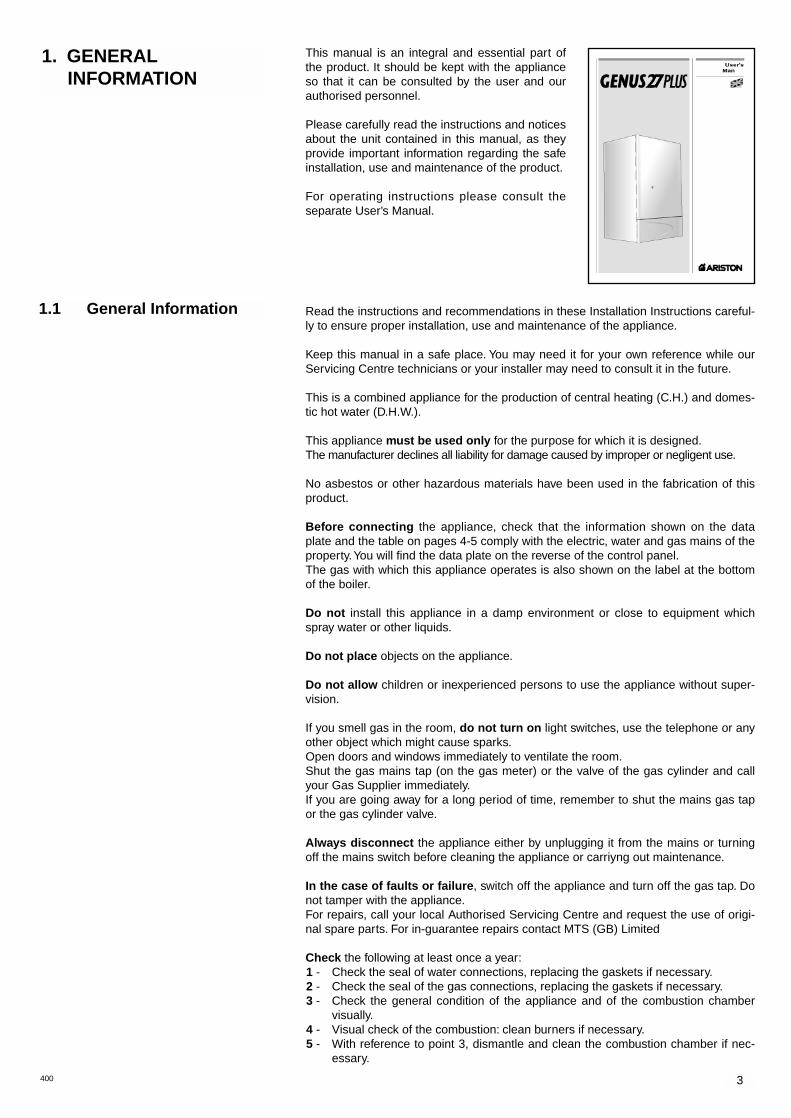
This manual is an integral and essential part ofthe product. It should be kept with the applianceso that it can be consulted by the user and ourauthorised personnel.
Please carefully read the instructions and noticesabout the unit contained in this manual, as theyprovide important information regarding the safeinstallation, use and maintenance of the product.
For operating instructions please consult theseparate User’s Manual.
Read the instructions and recommendations in these Installation Instructions careful-ly to ensure proper installation, use and maintenance of the appliance.
Keep this manual in a safe place. You may need it for your own reference while ourServicing Centre technicians or your installer may need to consult it in the future.
This is a combined appliance for the production of central heating (C.H.) and domes-tic hot water (D.H.W.).
This appliance must be used only for the purpose for which it is designed.The manufacturer declines all liability for damage caused by improper or negligent use.
No asbestos or other hazardous materials have been used in the fabrication of thisproduct.
Before connecting the appliance, check that the information shown on the dataplate and the table on pages 4-5 comply with the electric, water and gas mains of theproperty.You will find the data plate on the reverse of the control panel.The gas with which this appliance operates is also shown on the label at the bottomof the boiler.
Do not install this appliance in a damp environment or close to equipment whichspray water or other liquids.
Do not place objects on the appliance.
Do not allow children or inexperienced persons to use the appliance without super-vision.
If you smell gas in the room, do not turn on light switches, use the telephone or anyother object which might cause sparks.Open doors and windows immediately to ventilate the room.Shut the gas mains tap (on the gas meter) or the valve of the gas cylinder and callyour Gas Supplier immediately.If you are going away for a long period of time, remember to shut the mains gas tapor the gas cylinder valve.
Always disconnect the appliance either by unplugging it from the mains or turningoff the mains switch before cleaning the appliance or carriyng out maintenance.
In the case of faults or failure, switch off the appliance and turn off the gas tap. Donot tamper with the appliance.For repairs, call your local Authorised Servicing Centre and request the use of origi-nal spare parts. For in-guarantee repairs contact MTS (GB) Limited
Check the following at least once a year:1 - Check the seal of water connections, replacing the gaskets if necessary.2 - Check the seal of the gas connections, replacing the gaskets if necessary.3 - Check the general condition of the appliance and of the combustion chamber
visually.4 - Visual check of the combustion: clean burners if necessary.5 - With reference to point 3, dismantle and clean the combustion chamber if nec-
essary.
1. GENERAL INFORMATION
1.1 General Information

4 400
Legend:
1. Air Pressure Switch2. Fan3. Main Heat Exchanger4. Combustion Chamber 5. Ignition Electrodes and
Detection Electrodes6. Burner7. Automatic air release valve8. Gas Valve9. Spark Generator10. Circulation Pump11. Motorised Valve with by-pass12. Main Circuit Flow Switch13. Safety Valve (3 bar)14. Low pressure switch15. Expansion relief valve (6 bar)16. C.H. expansion Vessel17. D.H.W. expansion Vessel18. Drain point19. C.H.W. Probe20. Overheat Thermostat21. D.H.W. Storage with insulation shell
Fig. 1.1
1.2 Overall View
6 - With reference to point 4, dismantle and clean the injectors if necessary.7 - Visual check of the primary heat exchanger:
- check for overheating of the exchangers fins;- clean the exhaust side of the exchanger and fan if necessary.
8 - Regulate the gas pressure, ignition pressure, partial flame, maximum flame.9 - Check proper operation of the heating safety system:
- maximum safety temperature;- maximum safety pressure.
10 - Check the proper operation of the gas safety system:- gas or flame safety device;- gas valve safety device.
11 - Check that the electrical connections have been made in compliance wit h theinstructions shown in the Installation Instructions.
12 - Check the efficiency of the hot water supply (flow and temperature).13 - Check pressure in the Domestic Expansion Vessel and top up as necessary.14 - Check manually by turning the test knob the Temperature & Pressure Relief Valve.15 - Check manually by turning the test knob the Expansion Relief Valve.16 - Check discharge pipes from both the central heating and domestic hot water
for obstructions.17 - Check general operation of the appliance.18 - Check the exhaust system for the combustion products.
IN003A
5
The technical information and instructions provided herein below are intended forthe installer so that the unit may be installed correctly and safely.
WATER REGULATIONSThese regulations ensure a good supply of wholesome water, and that only approvedmaterials, pipes and fittings are used to convey water.
BUILDING REGULATIONSThese are a statutory document and take priority over all other regulations and recom-mendations. The installation of an unvented hot water storage cylinder is classified as a"Controlled Service" and Regulation G3 applies. To meet the requirements of theRegulation, installation of an unvented system should be undertaken by a "competentinstaller".
All installations of unvented hot water storage systems having a capacity of more than15 litres should be notified to the relevant Local Authority by means of building notice orby the submission of full plans. It is important to note that it is a criminal offense toinstall an unvented hot water storage system without notifying the Local Authority.
The installation and initial startup of the boiler must be by a CORGI ApprovedInstaller in compliance with the installation standards currently in effect, as well aswith any and all local health and safety standards i.e. CORGI.
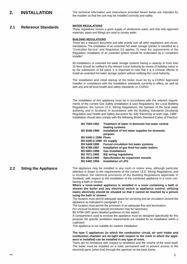
The installation of this appliance must be in accordance with the relevant require-ments of the current Gas Safety (installation & use) Regulations, the Local BuildingRegulations, the current I.E.E. Wiring Regulations, the byelaws of the local waterauthority, and in Scotland, in accordance with the Building Standards (Scotland)Regulation and Health and Safety document No. 635 “Electricity at work regs. 1989”.Installation should also comply with the following British Standard Codes of Practice:
The appliance may be installed in any room or indoor area, although particularattention is drawn to the requirements of the current I.E.E. Wiring Regulations, andin Scotland, the electrical provisions of the Building Regulations applicable inScotland, with respect to the installation of the combined appliance in a room con-taining a bath or shower.Where a room-sealed appliance is installed in a room containing a bath orshower the boiler and any electrical switch or appliance control, utilisingmains electricity should be situated so that it cannot be touched by a personusing the bath or shower.The location must permit adequate space for servicing and air circulation around theappliance as indicated in paragraph 2.4.The location must permit the provision of an adequate flue and termination.For unusual locations special procedures may be necessary.BS 6798-1987 gives detailed guidance on this aspect.A compartment used to enclose the appliance must be designed specifically for thispurpose. No specific ventilation requirements are needed for an installation within acupboard This appliance is not suitable for outdoor installation.
The type C appliances (in which the combustion circuit, air vent intake andcombustion chamber are air-tight with respect to the room in which the appli-ance is installed) can be installed in any type of room.There are no limitations with respect to ventilation and the volume of the room itself.The boiler must be installed on a solid, permanent wall to prevent access to theelectrical parts (when live) through the aperture on the back frame.
2. INSTALLATION
2.1 Reference Standards
2.2 Siting the Appliance
400
BS 7593:1992 Treatment of water in domestic hot water central heating systems
BS 5546:1990 Installation of hot water supplies for domestic purpoes
BS 5440-1:1990 FluesBS 5440-2:1989 Air supplyBS 5449:1990 Forced circulation hot water systemsBS 6789:1987 Installation of gas fired hot water boilersBS 6891:1989 Gas installationsBS 7671:1992 IEE wiring regulationsBS 4814:1990 Specification for expansion vesselsBS 5482:1994 Installation of LPG
6 400
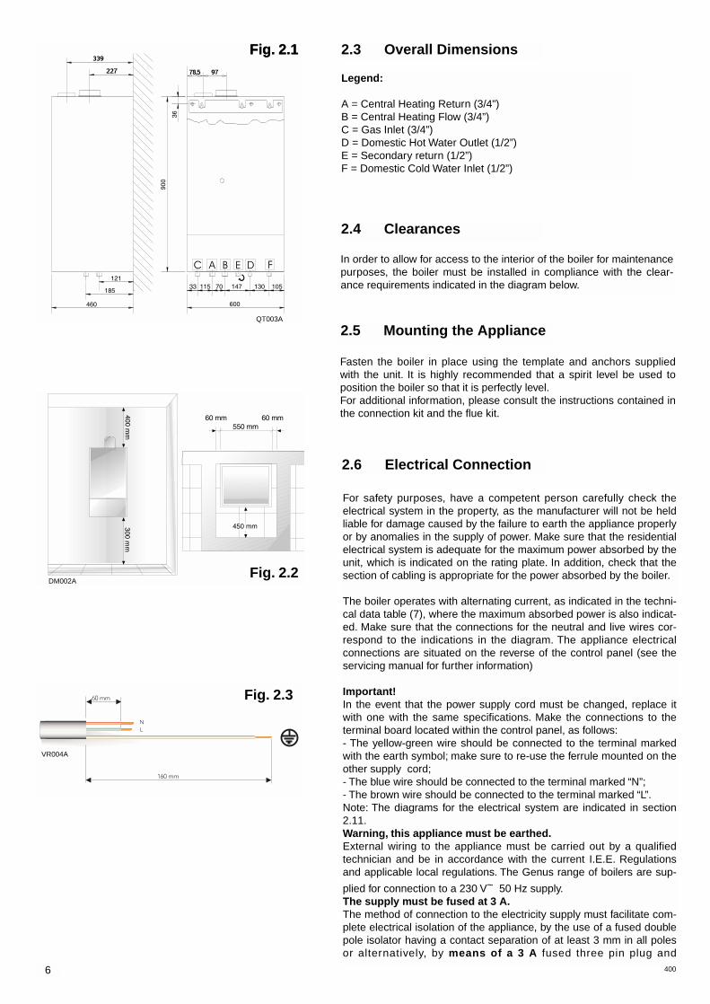
Fasten the boiler in place using the template and anchors suppliedwith the unit. It is highly recommended that a spirit level be used toposition the boiler so that it is perfectly level.For additional information, please consult the instructions contained inthe connection kit and the flue kit.
2.5 Mounting the Appliance
2.6 Electrical Connection
Fig. 2.3
Legend:
A = Central Heating Return (3/4”)B = Central Heating Flow (3/4”)C = Gas Inlet (3/4”)D = Domestic Hot Water Outlet (1/2”)E = Secondary return (1/2”)F = Domestic Cold Water Inlet (1/2”)
2.3 Overall Dimensions
In order to allow for access to the interior of the boiler for maintenancepurposes, the boiler must be installed in compliance with the clear-ance requirements indicated in the diagram below.
2.4 Clearances
Fig. 2.1
Fig. 2.2
For safety purposes, have a competent person carefully check theelectrical system in the property, as the manufacturer will not be heldliable for damage caused by the failure to earth the appliance properlyor by anomalies in the supply of power. Make sure that the residentialelectrical system is adequate for the maximum power absorbed by theunit, which is indicated on the rating plate. In addition, check that thesection of cabling is appropriate for the power absorbed by the boiler.
The boiler operates with alternating current, as indicated in the techni-cal data table (7), where the maximum absorbed power is also indicat-ed. Make sure that the connections for the neutral and live wires cor-respond to the indications in the diagram. The appliance electricalconnections are situated on the reverse of the control panel (see theservicing manual for further information)
Important!In the event that the power supply cord must be changed, replace itwith one with the same specifications. Make the connections to theterminal board located within the control panel, as follows:- The yellow-green wire should be connected to the terminal markedwith the earth symbol; make sure to re-use the ferrule mounted on theother supply cord;- The blue wire should be connected to the terminal marked “N”;- The brown wire should be connected to the terminal marked “L”.Note: The diagrams for the electrical system are indicated in section2.11.Warning, this appliance must be earthed.External wiring to the appliance must be carried out by a qualifiedtechnician and be in accordance with the current I.E.E. Regulationsand applicable local regulations. The Genus range of boilers are sup-
plied for connection to a 230 V~ 50 Hz supply.The supply must be fused at 3 A.The method of connection to the electricity supply must facilitate com-plete electrical isolation of the appliance, by the use of a fused doublepole isolator having a contact separation of at least 3 mm in all polesor alternatively, by means of a 3 A fused three pin plug and
Fig. 2.1
QT003A
DM002A
VR004A

7400
Central HeatingDetailed recommendations are given in BS 6798:1987 and BS 5449-1:1990, the fol-
lowing notes are given for general guidance.Pipe Work:
Copper tubing to BS EN 1057:1996 is recommended for water pipes. Jointing shouldbe either with capillary soldered or compression fittings.Where possible pipes should have a gradient to ensure air is carried naturally toair release points and water flows naturally to drain taps.The appliance has a built-in automatic air release valve, however it should beensured as far as possible that the appliance heat exchanger is not a natura col-lecting point for air.Except where providing useful heat, pipes should be insulated to prevent heatloss and avoid freezing.Particular attention should be paid to pipes passing through ventilated spaces inroofs and under floors.
By-pass:The appliance includes an automatic by-pass valve, which protects the mainheat exchanger in case of reduced or interrupted water circulation through theheating system, due to the closing of thermostatic valves or cock-type valveswithin the system.
System Design:This boiler is suitable only for sealed systems.
Drain Cocks:These must be located in accessible positions to permit the draining of thewhole system. The taps must be at least 15mm nominal size an manufactured inaccordance with BS 2870:1980.
Safety Valve Discharge:The discharge should terminate facing downwards on the exterior of the buildingin a position where discharging (possibly boiling water & steam) will not createdanger or nuisance, but in an easily visible position, and not cause damage toelectrical components and wiring.The discharge must not be over an entrance or a window or any other type ofpublic access.
2.7 Gas Connection The local gas region contractor connects the gas meter to the service pipe.If the gas supply for the boiler serves other appliances ensure that an adequate sup-ply is available both to the boiler and the other appliances when they are in use atthe same time.Pipe work must be of an adequate size. Pipes of a smaller size than the boiler inletconnection should not be used.
2.8 Water Connections
AC B D
EH I
F
View of the Boiler Connections
Fig. 2.4
unswitched shuttered socket outlet both complying with BS 1363.The point of connection to the Electricity supply must be readily accessible and adja-cent to the appliance unless the appliance is installed in a bathroom when this mustbe sited outside the bathroom.
Legend:
A = Central Heating Return (3/4”)B = Central Heating Flow (3/4”)C = Gas Inlet (3/4”)D = Domestic Hot Water Outlet (1/2”)E = Secondary return (1/2”)F = Domestic Cold Water Inlet (1/2”)H = Central Heating DischargeI = Domestic Hot Water Discharge
SC002A

8 400
Discharge pipework1) The tundish must be installed directly below the discharge outlet connection of the
boiler. The tundish must also be in a position visible to the occupants, and positionedaway from any electrical devices. The discharge pipe from the tundish should termi-nate in a safe place where there is no risk to persons in the vicinity of the dischargeand to be of metal.
2) Discharge pipes from the temperature & pressure relief are expansion relief valve arejoined together within the appliance.
3) The pipe diameter must be at least one pipe size larger than the nominal outlet size ofthe safety device unless it's total equivalent hydraulic resistance exceeds that of astraight pipe 9m long.I.e. Discharge pipes between 9m and 18m equivalent resistance length should be atleast 2 sizes larger than the nominal outlet size of the safety device. Between 18mand 27m at least 3 sizes larger, and so on.Bends must be taken into account in calculating the flow resistance.See fig. 2.4.1 and Table 1.
4) The discharge pipe must have a vertical section of pipe at least 300m in length, belowthe tundish before any elbows or bends in the pipework.
5) The discharge pipe must be installed with a continuous fall.6) The discharge must be visible at both the tundish and the final point of discharge, but
where this is not possible or practically difficult; there should be clear visibility at oneor other of these locations. Examples of acceptance are:i) Ideally below a fixed grating and above the water seal in a trapped gully.ii) Downward discharges at a low level; i.e. up to 100mm above external surfaces suchas car parks, hard standings, grassed areas etc. These are acceptable providing thatwhere children may play or otherwise come into contact with discharges, a wire cage orsimilar guard is positioned to prevent contact, whilst maintaining visibility.iii) Discharges at high level; I.e. into a metal hopper and metal down pipe with the endof the discharge pipe clearly visible (tundish visible or not). Or onto a roof capable ofwithstanding high temperature discharges of water 3m from any plastic guttering sys-tems that would take such a discharge (tundish visible).iv) Where a single pipe serves a number of discharges, such as in blocks of flats, thenumber served should be limited to not more than 6 systems so that any installationcan be traced reasonably easily. The single common discharge pipe should be atleast one pipe size large than the largest individual discharge pipe to be connected. Ifunvented hot water storage systems are installed where discharges from safetydevices may not be apparent I.e. in dwellings occupied by the blind, infirm or disabledpeople, consideration should be given to the installation of an electronically operateddevice to warn when discharge takes place.Note: The discharge will consist of scalding water and steam. Asphalt, roofing feltand non-metallic rainwater goods may be damaged by such discharges.WarningrThe outlet from the temperature & pressure relief valve must not be used for any otherpurpose.The temperature & pressure relief valve must not be removed in any circumstances.Any of the above will totally invalidate the warranty.NoteThe discharge from the central heating and domestic hot water systems may bejoined together after the tundish.
500 mm Max.
300 mmMin.
Temperature & pressurerelief valve
Metal discharge pipe (D1) fromtemperature & pressure relief valve.to tundish.
Metal discharge pipe (D2) from tundishwith continuous fall. See Table 2 and workedexample.
Tundish
Fixed grating
Trapped gulley
Discharge belowfixed grating.(see page 6 foralternative pointsof discharge).
Table 1. Sizing of copper discharge pipe“D2” for common temperaturevalve outlet sizes.
WORKED EXAMPLEThe example below is for a G 1/2 Temperature & Pressure Relief valve with a dis-charge pipe (D2) having 4 no. elbows and length of 7m from the Tundish to the pointof discharge.From Table 1Maximum resistance allowed for a straight length of 22mm copper discharge pipe(D2) from G 1/2 T & P valve is 9m.Subtract the resistance for 4 no. 22mm elbows at 0.8m each = 3.2m.Therefore the maximum permitted length equates to: 5.8m.
As 5.8m is less than the actual length of 7mtherefore calculate the next largest size.Maximum resistance allowed for a straightlength of 28mm pipe (D2) from G 1/2 T & Pvalve equates to: 18m.Subtract the resistance for 4 no. 28mm elbowat 1.0m each = 4m.Therefore the maximum permitted lengthequates to: 14mAs the actual length is 7m, a 28mm (D2) cop-per pipe will be satisfactory.
Valve outlet size Minimum size ofdischarge pipe D1*
Minimum size ofdischarge pipe D2*
from tundish
Maximumresistance allowed,
expressed as alength of pipe (i.e.
no elbow or bends)
Resistance createdby each elbow or
bend
G 1/2 15 mm 22 mm28 mm35 mm
Up to 9 mUp to 18 mUp to 27 m
0.8 m1.0 m1.4 m
G 3/4 22 mm 28 mm35 mm42 mm
Up to 9 mUp to 18 mUp to 27 m
1.0 m1.4 m1.7 m
G 1 28 mm 35 mm42 mm54 mm
Up to 9 mUp to 18 mUp to 27 m
1.4 m1.7 m2.3 m
Fig. 2.4.1
SH
005A
TB004A

9400
Air Release Points:These must be fitted at all high points where air naturally collects and must besited to facilitate complete filling of the system.The appliance has an integral sealed expansion vessel to accommodate theincrease of water value when the system is heated.It can accept up to 7 l (1.5 gal) of expansion water. If the heating circuit has anunusually high water content, calculate the total expansion and add an additionalsealed expansion vessel with adequate capacity.
Mains Water Feed - Central Heating:There must be no direct connection to the mains water supply even through anon-return valve, without the approval of the Local Water Authority.
Filling:A temporary method for initially filling the system and replacing lost water duringservicing and initial filling (complying to current water regulations) must be pro-vided. The flexible hose must be removed once the system has been filled. TheD.H.W. inlet valve on the connection kit has two postions, one for winter and onefor the summer. This enables the flow-rate through the appliance to be adjustedso that a sensible D.H.W. temperature may be achieved throughout the year.
Domestic WaterThe domestic water must be in accordance with the relevant recommendation of BS5546:1990. Copper tubing to BS EN 1057:1996 is recommended for water carryingpipe work and must be used for pipe work carrying drinking water.Note: This appliance is capable of producing domestic hot water of up to
70˚C. For extra security against scalding a thermostatic blending valvemay be installed on the domestic hot water outlet.
Secondary ReturnThe secondary return can be used as an option. A Non Return Valve (not supplied) mustbe fitted to prevent back flow and a Bronze Pump will be needed in conjunction with aPipe Thermostat to circulate the hot water (both not supplied).
Residual Head of the Boiler
A: Gas inletB: C.H.W. returnC: C.H.W. flowD: D.H.W. secondary returnE: D.H.W. flowF: D.H. inlet
1 - Gas meter inlet cock2 - Gas meter3 - Gas meter outlet cock4 - Internal gas cock5 - Appliance gas inlet cock6 - D.W. inlet cock7 - D.H.W. expansion vessel8 - cock9 - Secondary return pump
10 - Thermostat11 - Time control clock12 - Radiator control clock13 - Holder14 - Air release valve15 - Drain valve16 - T&P valve17 - Safety valve18 - Tundish
Fig. 2.5
Fig. 2.5.1
VR
005A
SH006A

Flue SystemThe provision for satisfactory flue termination must be made asdescribed in BS 5440-1.The appliance must be installed so that the flue terminal is exposed tooutdoor air.The terminal must not discharge into another room or space such asan outhouse or lean-to.It is important that the position of the terminal allows a free passage ofair across it at all times.The terminal should be located with due regard for the damage or dis-colouration that might occur on buildings in the vicinity.In cold or humid weather water vapour may condense on leaving theflue terminal.The effect of such “steaming” must be considered.If the terminal is less than 2 metres above a balcony, above ground orabove a flat roof to which people have access, then a suitable terminalguard must be fitted. When ordering a terminal guard, quote the appli-ance model number.A suitable terminal guard is available from:TOWER FLUE COMPONENTSMorley RoadTonbridgeKent TN9 1RAThe minimum acceptable spacing from the terminal to obstructionsand ventilation openings are specified in Fig. 2.6
The boiler is designed to be connected to a coaxial flue dischargesystem.
TERMINAL POSITION mm
A - Directly below an open window or other opening 300B - Below gutters, solid pipes or drain pipes 75C - Below eaves 200D - Below balconies or car-port roof 200E - From vertical drain pipes and soil pipes 75F - From internal or external corners 300G - Above ground or below balcony level 300H - From a surface facing a terminal 600I - From a terminal facing a terminal 1200J - From an opening in the car port
(e.g. door, window) into dwelling 1200K - Vertically from a terminal in the same wall 1500L - Horizontally from a terminal in the same wall 300
A
BC
D
E
F
G
J
K
HI
L
GF
Fig. 2.6
2.9 Flue Connections
10 400
In addition, it is also possible to use a splitsystem by fitting a special adapter to theflue discharge collar and using one of theapertures for the air vent intake locatedon the top part of the combustion cham-ber (A).
Fig. 2.8
Fig. 2.7
FU010A
FU011A
FU012A

In Fig. 2.11 below, several differenttypes of flue systems are shown.For additional information regarding theflue accessories, please consult theFlue Pipe Accessories manual.
Fig. 2.11
In calculating the lengths of the pipes, the maximum length must also take into con-sideration the values for the exhaust/air intake end terminals, as well as 90° elbowsfor coaxial systems.The C52 types must comply with the following requirements:1. The discharge/intake vent pipes must have the same diameter of ø 80 mm.2. If an elbow is inserted into the discharge/ventilation system, the calculation of the
overall extension must take into consideration the values for each curve, as indi-cated in the table.
3. The exhaust pipe must extend at least 0.5 m above the ridge of the roof if it islocated on a side other than that for the air intake (this is not obligatory if theexhaust and air intake pipes are located on the same side of the building).
(*) L = Length of Piping
C12 (xx) 4 m ø 60 /100 NOCoaxialSystem C32 (xx) 4 m ø 60 /100 NO
C42 (xx) 4 m ø 60 /100 NO
C12 (xy) 34 m ø 80 L < 4.5 m L > 6.6 m
C32 (xy) 34 m ø 80 L < 4.5 m L > 6.6 mSplit
Systems C42 (xy) 34 m ø 80 L < 4.5 m L > 6.6 m
C52 (xy) 56 m ø 80 L < 8 m L > 5.8 m
Maximum ExtensionExhaust/Air
Exhaust Type Diameter of Pipes(mm)
Use of ø 42 mm Restictoron Delivery Side
Risk of Condensation Forming
11400
This procedure must be done as follows:1 - Remove the air vent intake in the area
indicated in Fig. 2.9, by breaking theperforated ring.
2 - Use a tool to grasp the lid and removeit completely.
3 - Clean any burrs or sharp edges with aknife or an appropriate tool.
A
Fig. 2.9 Fig. 2.10
FU
013A
FU
014A
12 400
2.10 Room Thermostat Connection
1
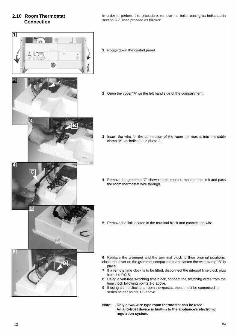
In order to perform this procedure, remove the boiler casing as indicated insection 3.2. Then proceed as follows:
1 Rotate down the control panel.
2 Open the cover “A” on the left hand side of the compartment.
3 Insert the wire for the connection of the room thermostat into the cableclamp “B”, as indicated in photo 3.
4 Remove the grommet “C” shown in the photo 4, make a hole in it and passthe room thermostat wire through.
5 Remove the link located in the terminal block and connect the wire.
6 Replace the grommet and the terminal block to their original positions,close the cover on the grommet compartment and fasten the wire-clamp “B” in
place.7 If a remote time clock is to be fitted, disconnect the integral time clock plug
from the P.C.B.8 Using a volt-free switching time clock, connect the switching wires from the
time clock following points 1-6 above.9 If using a time clock and room thermostat, these must be connected in
series as per points 1-8 above.
Note: Only a two-wire type room thermostat can be used.An anti-frost device is built-in to the appliance’s electronic regulation system.
2
3B
A
4
C
5
6
B
TA00
1A

13
2.11 Electrical Diagram
T
D.H.W.Heating+ D.H.W.
Flue Testoperatingmodes
Heating
AT
BT
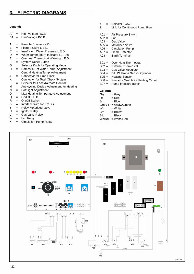
Legend:
AT = High Voltage P.C.B.BT = Low Voltage P.C.B.
A = Remote Connector KitB = Flame Failure L.E.D.C = Insufficient Water Pressure L.E.D.D = Water Temperature Indicator L.E.D.sE = Overheat Thermostat Warning L.E.D.F = System Reset ButtonG = Selector Knob for Operating ModeH = Domestic Hot Water Temp. AdjustmentI = Central Heating Temp. AdjustmentJ = Wire Connector for Room ThermostatK = Connector for Total Check SystemL = Selector for Local/Remote ControlM = Anti-cycling Device Adjustment for HeatingN = Soft-light AdjustmentO = Max Heating Temperature AdjustmentP = Time Clock Connection Q = On/Off L.E.D.R = On/Off SwitchS = Interface Wire for P.C.B.sT = Relay Motorised ValveU = Ignitor RelayV = Gas Valve RelayW = Fan RelayX = Circulation Pump RelayY = Selector TCS2Z = Link for Continuous Pump Run
A01 = Air Pressure SwitchA02 = FanA03 = Gas ValveA05 = Motorised ValveA06 = Circulation PumpA07 = Flame DetectorA08 = Earth Terminal
B01 = Over Heat ThermostatB02 = External ThermostatB03 = Gas Valve ModulatorB04 = D.H.W. Probe Sensor Cylinder B05 = Heating SensorB06 = Pressure Switch for Heating CircuitB07 = Minimum pressure switch
ColoursGry = GreyRd = RedBl = BlueGrn/Yll = Yellow/Green Wh = WhiteBrn = BrownBlk = BlackWh/Rd = White/Red
400
SE
003A

14 400
1
2
3
45
6
17
18
7
8
9
10
22 21 20
19
11 13 14 15 1612
2.12 Water Circuit Diagram
Legend:
1. Air Pressure Switch2. Fan3. Main Heat Exchanger4. Ignition Electrodes and Detection Electrodes5. Burner6. Gas Valve8. Spark Generator7. Automatic air release valve8. Circulation Pump9. Motorised Valve with by-pass10. Main Circuit Flow Switch11. Safety Valve (3 bar)12. Low pressure switch13. C.H. expansion Vessel14. D.H.W. expansion Vessel15. D.H.W. Storage with insulation shell16. D.H.W. Probe17. Expansion relief valve (6 bar)18. Temperature/Pressure relief valve (7bar)19. Magnesium anode20. C.H.W. Probe21. Overheat Thermostat22. Drain point
SI0
03A

15400
3. COMMISSIONING
3.1 Initial Preparation
MTS (GB) Limited support the initiative. Within the information pack you will finda copy of the logbook. It is important that this is completed in the presence ofyour customer, they are shown how to us it, and it is signed by them. Please instruct yourcustomer that they must have their logbook with them whenever they contact aservice engineer or us.
Preliminary electrical system checks to ensure electrical safety must be carried out by acompetent person i.e. polarity, earth continuity, resistance to earth and short circuit.
Filling the Heating System:Remove the panels of the case and lower the control panel (see point 3.2. for further information).Open the central heating flow and return cocks supplied with the connection kit.Unscrew the cap on the automatic air release valve one full turn and leave open permanently.Close all air release valves on the central heating system.Gradually open valve(s) at the filling point (filling-loop) connection to the central heatingsystem until water is heard to flow, do not open fully.Open each air release tap starting with the lower point and close it only when clear water,free of air, is visible.Purge the air from the pump by unscrewing anticlockwise the pump plug and also man-ually rotate the pump shaft in the direction indicated by the pump label to ensure thepump is free.Close the pump plug.Continue filling the system until at least 1.5 bar registers on the pressure gauge.Inspect the system for water soundness and remedy any leaks discovered.
Filling of the D.H.W. System:Close all hot water draw-off taps.Open the cold water inlet cock supplied with the connection kit.Open slowly each draw-off tap and close it only when clear water, free of bubbles, is visible
Gas Supply:Inspect the entire installation including the gas meter, test for soundness and purge, all asdescribed in BS 6891:1988.Open the gas cock (supplied with the connection kit) to the appliance and check the gasconnector on the appliance for leaks.When the installation and filling are completed turn on the central heating system (sect.3.4) and run it until the temperature has reached the boiler operating temperature. Thesystem must then be immediately flushed through.The flushing procedure must be in line with BS 7593:1992 Code of practice for treatmentof water in domestic hot water central heating systems.During this operation, we highly recommend the use of a central heating flushing deter-gent (Fernox Superfloc or equivalent), whose function is to dissolve any foreign matterthat may be in the system.Substances different from these could create serious problems to the pump orother components.The use of an inhibitor in system such as Fernox MB-1 or equivalent is strongly recom-mended to prevent corrosion (sludge) damaging the boiler and system.Failure to carry out this procedure may invalidate the appliance warranty.
3.2 Removing the Casing
VR
006A
a
VR
006A
b
VR
006A
c

16 400
The boiler was designed to make regulation easy. Toaccess the adjustment and control area, simply remove thecover by unscrewing the screws “A” and “C” and lift up thesmall service panels “B1” and “B2” respectively.The first provides access to the control (low voltage)P.C.B., while the second makes it possible to work on thepower supply P.C.B.The service panel “B2” also providesaccess to:- the power supply cord connector;- the fuses;- the selector knob for continuous operation of the circulationpump.The service panel “B1” also provides access to:- the potentiometer for regulating the ignition delay (anti-cycling) feature, which can be set from 0 to 2 minutes (factoryset at 1 minute);- the potentiometer for regulating the soft-light feature, the set-
3.4 Initial Start-up The checks to be run before initial start-up are as follows:1. Make sure that:
- the screw on the automatic air valve has been loosened when the system is full;- If the water pressure in the system is below 1.5 bar, bring it up to the appropriate
level;- Check to see whether the gas cock is closed;- Make sure that the electrical connection has been made properly and that the
earth wire is connected to an efficient earthing system;- Supply power to the boiler by pressing the On/Off switch <L> - the L.E.D. “I” will
turn on - turn the selector knob “C” to the <winter> setting. This will start the cir-culation pump. After 7 seconds, the boiler will signal a shut- down due to failureignition. Leave the boiler as it is until all of the air has been bled from the lines.
- Loosen the cap on the head of the pump to eliminate any air pockets;- Repeat the procedure for bleeding the radiators of air;- Open the taps for a brief period;- Check the system pressure and, if it has dropped, open the filling loop again to
bring the pressure back up to 1.5 bar.2. Check the exhaust flue for the fumes produced by combustion.3. Make sure that all gate valves are open;4. Turn on the gas cock and check the seals on the connections, including the onefor the burner, making sure that the meter does not signal the passage of gas. Checkthe connections with a soap solution and eliminate any leaks.5. Press the reset button “A” for the lighting system; the spark will light the mainburner. If the burner does not light the first time, repeat the procedure.6. Check the minimum and maximum pressure values for the gas going to the burn-er; adjust it if needed using the values indicated in the table in section 4. (See sect ofthe servicing manual).3.5 Operational
Adjustments
3.3 Control Panel
Legend:
A Ignition Faliure Reset/Safety Thermostat Reset
B L.E.D. for Ignition FaliureC Selector Knob for Summer/Winter/
Flue Test ModesD L.E.D. for Insufficient System PressureE Domestic Hot Water Temperature ControlF Central Heating Temperature
Indicating LedsG L.E.D. for Safety Thermostat (overheating)H Heating Temperature Adjustment Knob I L.E.D. for ON/OFF SwitchL ON/OFF SwitchO Heating System Pressure Gauge
* Warning the flue analysis mode must only be selected by a qualified service engineer.
FR
004A
FO
005A
The boiler is equipped with the following safety systems (see section 3.3 for refer-ences):1. - Ignition FailureThis control signals an ignition failure on the burner 7 seconds after a lighting failure.The L.E.D. “B” will turn on to signal the shutdown status.The system can be reset by pressing and releasing the button “A” after checking tomake sure that the gas valve is open. Repeat this process until the burner lights.2. - Circulation FailureThis control signals that the safety pressure switch on the primary circuit has notsensed a pressure of at least 1.5 bar within 40 seconds of the activation of the circu-lation pump, it shuts off the boiler and lights the L.E.D. “D” The system can be reset(after the pressure has been brought up to the proper level) by using the On/Offswitch “L”.3. - OverheatingThis control shuts off the boiler in the case where the primary circuit reaches a tem-perature in excess of 110°C. The L.E.D. “G” will come on to signal this shut-off sta-tus. After the system has been allowed to cool, the system can be reset by pressingthe button “A”.4. - Anti-frost DeviceThe boiler is equipped with a device that automatically lights the main burner whenthe temperature in the delivery line to the system drops below 5°C. The boiler willcontinue to operate until the temperature in question reaches about 58°C.This device is activated on a properly operating boiler if:- the system pressure is between the acceptable values;- the power supply to the unit is on;- the unit is supplied with gas.This feature is enabled also when the boiler is in summer operating mode.5. - Safety Shut-offAt the start of every lighting phase, the P.C.B. performs a series of internal controls.If a malfunction occurs, the boiler will shutdown until the problem has been resolved.
3.8 Boiler Safety Systems
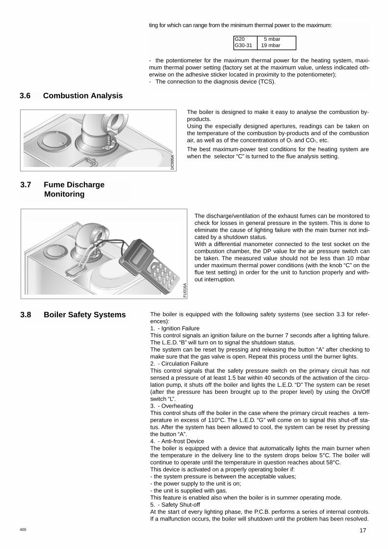
3.6 Combustion Analysis
The boiler is designed to make it easy to analyse the combustion by-products.Using the especially designed apertures, readings can be taken onthe temperature of the combustion by-products and of the combustionair, as well as of the concentrations of O2 and CO2, etc.
The best maximum-power test conditions for the heating system arewhen the selector “C” is turned to the flue analysis setting.
The discharge/ventilation of the exhaust fumes can be monitored tocheck for losses in general pressure in the system. This is done toeliminate the cause of lighting failure with the main burner not indi-cated by a shutdown status.With a differential manometer connected to the test socket on thecombustion chamber, the DP value for the air pressure switch canbe taken. The measured value should not be less than 10 mbarunder maximum thermal power conditions (with the knob “C” on theflue test setting) in order for the unit to function properly and with-out interruption.
3.7 Fume Discharge Monitoring
17400
ting for which can range from the minimum thermal power to the maximum:
- the potentiometer for the maximum thermal power for the heating system, maxi-mum thermal power setting (factory set at the maximum value, unless indicated oth-erwise on the adhesive sticker located in proximity to the potentiometer);- The connection to the diagnosis device (TCS).
G20 5 mbarG30-31 19 mbar
DC
005A
FU
016A
3.9 Draining the System Draining the heating system.The heating system must be emptied as follows:- Turn off the boiler;- Open the drain valve for the system and place a container below to catch the waterthat comes out;- Empty the system at the lowest points (where present). If you plan on not using theheating system for an extended period of time, it is recommended that you addantifreeze with an ethylene glycol base to the water in the heating lines and radiatorsif the ambient temperature drops below 0°C during the winter.
This makes repeated draining of the entire system unnecessary.
Draining the domestic hot water system.Whenever there is the danger of the temperature dropping below the freezing point,the domestic hot water system must be drained as follows:- Turn off the general water valve for the the household plumbing system;- Turn on all the hot and cold water taps;- Empty the remaining water from the lowest points in the system (where present).
18 400
5. Adjust the soft-light feature;6. Adjust the delayed lighting feature for the heating system (can be set from 0 to 2mins.).
CATEGORY II2H3+ Methane Gas Liquid Butane Gas Liquid Propane GasG20 G30 G31
Recommended Soft-light Pressure(mbar) 5-5.4 13.4 13.4
Lower Wobbe Index (15°C;1013mbar) MJ/m3h 45.67 80.58 70.69Nominal Delivery Pressure mbar 20 30 37Minimum Delivery Pressure mbar 17 20 25
GENUS 27 BFFI PLUS
Main Burner: n. 15 jets (ø) mm 1.25 0.72 0.72Consumption (15°C; 1013mbar) m3/h 3.16 ---- ----Consumption (15°C; 1013mbar) Kg/h ---- 2.35 2.32Gas Cock Outlet Pressuremax - min mbar 11.0- 2.0 (*) - 5.0 (*) - 7.0
4. GAS ADJUSTMENTS
(1mbar = 10,197column of water)The outlet pressure of the gas cock is obtained by completely loosening the screw on the solenoid. The maximum pressure of the gas to theburner will be equal to the nominal delivery pressure minus the head loss within the gas valve.
CATEGORY II2H3+ Methane GasG20
Liquid Butane GasG30
Liquid Propane GasG31
4.1 Changing the Type of Gas
The boiler can be converted to use either methane (natural) gas (G20) or LPG(G30 - G31) by an Authorised Service Centre.The operations that must be performed are the following:1. Replace the jets on the main burner (see table in section 4);2. Adjust the maximum and minimum thermal capacity values for the boiler (seetable in section 4);3. Replace the gas rating plate;4. Adjust the maximum thermal power setting;
400
It is recommended that the following checks be made on the boiler at leastonce a year:1 - Check the seals for the water connections; replacement of any faulty seals.2 - Check the gas seals; replacement of any faulty gas seals.3 - Visual check of the entire unit.4 - Visual check of the combustion process and cleaning of the burners if needed.5 - If called for by check no. 3, dismantling and cleaning of the combustion chamber.6 - If called for by check no. 4, dismantling and cleaning of the injectors.7 - Visual check of the primary heat exchanger:
- check for overheating in the blade assembly;- clean the exhaust fan if needed.
8 - Adjustment of the flow rate of the gas: flow rate for lighting, partial load and full load.9 - Check of the heating safety systems:
- safety device for maximum temperature;- safety device for maximum pressure.
10 - Check of the gas safety systems:- safety device for lack of gas or flame ionisation (detection electrode);- safety device for gas cock.
11 - Check of the electrical connection (make sure it complies with the instructions in the manual).
12 - Check of domestic hot water production efficiency (delivery rate and temperature)13 - Check pressure in the Domestic Expansion Vessel and top up as necessary.14 - Check manually by turning the test knob the Temperature & Pressure Relief Valve.15 - Check manually by turning the test knob the Expansion Relief Valve.16 - Check discharge pipes from both the central heating and domestic hot water
for obstructions.17 - Check of the general performance of the unit.18 - General check of the discharge/ventilation of the combustion by products.
5. MAINTENANCE
19

400
Co
d.2
3 99
84
1516
000
29.8/12.027.4/10.3
92.1
88.81.16.80.456.91.33.16
2.35/2.32
136.97.27
7.45
55+5
82/4260
40/70183
0.2/671
145320
30-37230 / 50
200X4D2A86
47-116-11
GENUS 27 BFFI PLUS
CE CertificationThermal Capacity max/min kWThermal Power max/min kWEfficiency of Nominal Thermal Capacity %Efficiency at 30% of Nominal ThermalCapacity %Heat Loss to the Shell (∆=50°C) %Flue Heat Loss with Burner Operating %Flue Heat Loss with Burner Off %Maximum Discharge of Fumes (methane) Kg/hResidual Discharge Head mbarConsumption at Nominal Catacity (G20-G25) m3/h(15°C, 1013 mbar) (G30-G31) Kg/hTemp. of exhaust fumes at nominalcapacity with methane °CCO2 Content %
O2 Content %
CO Content ppmMinimum Ambient Temperature °CHeating Temperature max/min °CStored D.H.W. Cylinder Capacity lStored D.H.W. min/max Temperature max/min °CSpecific flow rate* (IN 10’ ∆T=30°C) l/minD.H.W. Expansion Vessel lPressure of Domestic Hot Water max/min barExpansion Vessel Capacity lPreload Charge barMaximum Water Content in System lMaximum Heating Pressure barNominal Pressure Natural Gas (G20) mbar
Liquid Gas (G30/G31) mbarVoltage/Frequency of Power Supply V/HzTotal Electrical Power Absorbed WProtection Grade of Electrical System IPInternal Fuse RatingWeight Kg
GC Number
6. TECHNICAL INFORMATION
*BS EN 625
Manufacturer: Merloni TermoSanitari SpA - Italy
Commercial subsidiary: MTS (GB) LIMITEDMTS BuildingHughenden AvenueHigh WycombeBucks HP13 5FT
Telephone: (01494) 755600
Fax: (01494) 459775
Internet: http://www.mtsgb.ltd.uk
E-mail: [email protected]
Technical Service Hot Line: (01494) 539579

Servicing InstructionsType C BoilersG.C.N: 47-116-11
LEAVE THESE INSTRUCTIONSWITH THE END USER

2
1. SERVICING INSTRUCTIONS
1.1 Replacement of Parts
1.2 To Gain General Access1.2.1 Removing the front panel1.2.2 Removing side panels1.2.3 Removing the control panel door
1.3 Access to the Combustion Chamber1.3.1 Removing the sealed chamber front cover1.3.2 Removing the combustion cover1.3.3 Removing the burner and injectors1.3.4 Removing the electrodes1.3.5 Removing the main heat exchanger1.3.6 Removing the air pressure switch1.3.7 Removing the fan
1.4 Servicing and Removal of the Gas Valve1.4.1 Setting gas pressures1.4.2 Removing the spark generator1.4.3 Removing the gas valve
1.5 Access to the Water Circuit1.5.1 Removing the main flow switch1.5.2 Removing the pump pressure switch1.5.3 Removing the safety valve1.5.4 Removing the automatic air vent1.5.5 Removing the pump1.5.6 Removing the pressure gauge1.5.7 Removing the expansion vessel1.5.8 Removing the overheat thermostat1.5.9 Removing the heating temperature sensor (N.T.C.)1.5.10 Removing temperature and pressure relief valve1.5.11 Removing the D.H.W. probe1.5.12 Removing the diverter valve
1.6 Access to the Control System1.6.1 Checking the Fuses1.6.2 Removing the Time Clock 1.6.3 Removing the P.C.B.s
2. FAULT FINDING
2.1 Fault Finding Guide (Flow-chart)
3. ELECTRICAL DIAGRAMS
4. SHORT SPARE PARTS LIST
TABLE OF CONTENTS

3
1. SERVICING INSTRUCTIONS
The life of individual components vary and they will need servicingor replacing as and when faults develop.The fault finding sequence chart in chapter 2 will help to locatewhich component is the cause of any malfunction, and instructionsfor removal, inspection and replacement of the individual parts aregiven in the following pages.
1.1 Replacement of Parts
1.2 To Gain General Access
To ensure efficient safe operation, it is recommended that the boil-er is serviced annually by a competent person.
Before starting any servicing work, ensure both the gas andelectrical supplies to the boiler are isolated and the boiler iscool.Before and after servicing, a combustion analysis should be madevia the flue sampling point (please refer to the Installation Manualfor further details).
After servicing, preliminary electrical system checks must be car-ried out to ensure electrical safety (i.e. polarity, earth continuity,resistance to earth and short circuit).
Fig. 1.1
Fig. 1.2
A
All testing and maintenance operations on the boiler require thecontrol panel to be lowered. This will also require the removal ofthe casing.
1.2.1 Removing the front pannel:1. Remove the screw “A” from the centre of the top edge of the
front panel and remove the panel by lifting upward (see fig. 1.1);
2. Remove the front panel from the rest of the casing (see fig. 1.2).
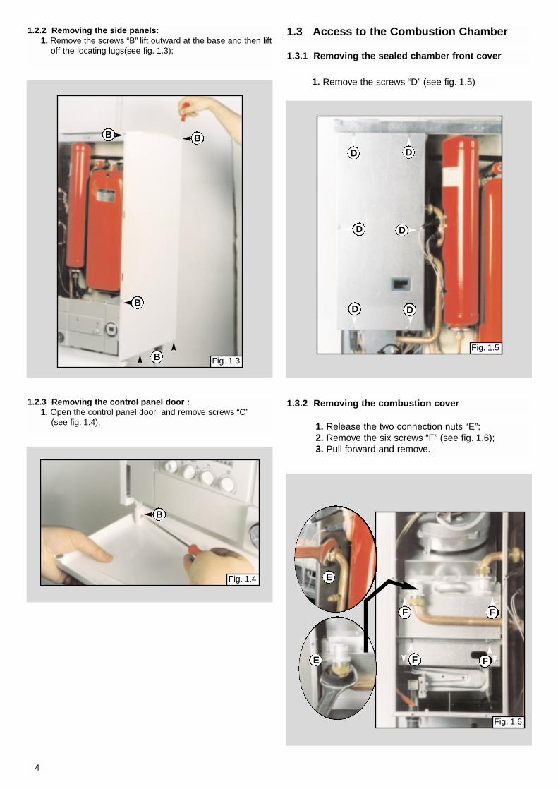
1.3.1 Removing the sealed chamber front cover
1. Remove the screws “D” (see fig. 1.5)
Fig. 1.5
D
D D
D
DD
1. Release the two connection nuts “E”;2. Remove the six screws “F” (see fig. 1.6);3. Pull forward and remove.
1.3.2 Removing the combustion cover
E
E
F F
FF
Fig. 1.6
1.3 Access to the Combustion Chamber
4
1.2.2 Removing the side panels:1. Remove the screws “B” lift outward at the base and then lift
off the locating lugs(see fig. 1.3);
B
B
B B
Fig. 1.3
B
Fig. 1.4
1.2.3 Removing the control panel door :1. Open the control panel door and remove screws “C”
(see fig. 1.4);
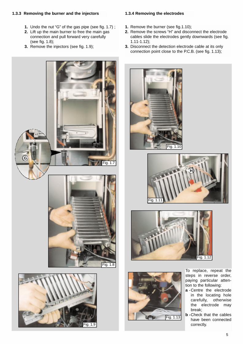
1.3.4 Removing the electrodes
1. Remove the burner (see fig.1.10);2. Remove the screws “H” and disconnect the electrode
cables slide the electrodes gently downwards (see fig.1.11-1.12);
3. Disconnect the detection electrode cable at its onlyconnection point close to the P.C.B. (see fig. 1.13);
5
1. Undo the nut “G” of the gas pipe (see fig. 1.7) ;2. Lift up the main burner to free the main gas
connection and pull forward very carefully (see fig. 1.8);
3. Remove the injectors (see fig. 1.9);
1.3.3 Removing the burner and the injectors
GFig. 1.7
Fig. 1.8
Fig. 1.9
Fig. 1.10
H
Fig. 1.11
Fig. 1.12
Fig. 1.13
To replace, repeat thesteps in reverse order,paying particular atten-tion to the following:a -Centre the electrode
in the locating holecarefully, otherwisethe electrode maybreak;
b -Check that the cableshave been connectedcorrectly.

6
Fig. 1.15
1. Drain the boiler of water;2. Release the connection nut “I” connecting the
exchanger to the flow pipes (see fig. 1.14);3. Lower the heat exchanger at its front end and lift
forward clear of the ledge at the rear (see fig.1.15)
4. Pull it straight out.
1.3.5 Removing the main heat exchanger
Fig. 1.14
I
1. Remove screws “L” on the top of the sealed cham-ber (see fig. 1.17);2. Pull upwards the plastic support plug (see fig. 1.18)3. Disconnect the electrical connections “J” and sili-cone pipes “K” from their connection points (see fig.1.16);
1.3.6 Removing the air pressure switch
J
K
L
L
K
Fig. 1.16
Fig. 1.18
Fig. 1.17
7
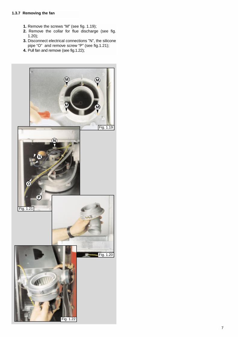
1. Remove the screws “M” (see fig. 1.19);2. Remove the collar for flue discharge (see fig.
1.20);3. Disconnect electrical connections ”N”, the silicone
pipe “O” and remove screw “P” (see fig.1.21);4. Pull fan and remove (see fig.1.22);
1.3.7 Removing the fan
Fig. 1.19
Fig. 1.20
Fig. 1.21
M
M
M
M
N
O
P
N
Fig. 1.22

8
1.4 Servicing and Removal of the Gas Valve
1
2
3
4
A
B
C
E
F
D
Setting the minimum and the maximum power of the boiler1. Check that the supply pressure to the gas valve is a minimum of 20 mbar
for natural gas.2. To do this, remove the screw “A” (Fig. a).
Fit the pipe of the pressure gauge to the pressure connection of the gasvalve “B”.When you have completed this operation, replace the screw “A” securelyinto its housing to seal off the gas.
3. To check the pressure supplied by the gas valve to the burner, remove thescrew “C” (Fig. b). Fit the pipe of the pressure gauge to the pressure out-let of the gas valve “D”.Disconnect the compensation pipe either from the gas valve or from the sealed chamber.
4. Set the On/Off button to position < I > and the "summer/winter" switch tothe flue test position.Turn on the hot water tap and allow the hot water tap to run at full rate.Adjust nut “E” (Fig. c) on the modureg to set the maximum gas pressure(displayed on the pressure gauge) turn the screw clockwise to increase thepressure and counter-clockwise to decrease, corresponding to the maxi-mum power (see table “A” page 8).
5. To set the minimum power, disconnect a supply lead from the moduregand adjust screw “F” (Fig. d) whilst holding the outer nut.Turn the screw clockwise to increase the pressure and coun-ter-clockwise to decrease the pressure (displayed on thepressure gauge) corresponding to the minimum power (see table “A” page 9).
6. When you have completed the above operations, turn off thehot water tap, re-connect the supply terminal to the moduregon the gas valve and replace the cap on the screw of themodureg.
Setting the maximum heating circuit power7. To set the maximum heating circuit power, place the
On/Off button to position < I > and the "summer/winter" switch to winterposition.Turn the knob of the heating thermostat clockwise to maximum;
8. Remove the left hand inspection panel of the P.C.B. and fit a smallcross-head screwdriver in to the right hand potentiometer. Turn clockwiseto increase the pressure or counter-clockwise to reduce the pressure.Adjust the setting to the required heating pressure value (displayed on thepressure gauge), as indicated in the diagrams shown in page 9.
9. Turn off the boiler by placing the main switch to the "Off" position.
Setting pressure for soft ignition.Disconnect the detection electrode connection from the P.C.B. (see fig.1.13).Start the boiler and during the ignition sequence adjust the centre poten-tiometer until the gas pressure reads the required gas pressure as per thetable below.Once the gas pressure is set turn off the boiler and reconnect the connec-tion to the P.C.B.NB.: It may be necessary to reset the flame failure reset a number of timesduring this operation.
Recommended pressure for slow ignition 5 mbar - 1.95 in w.g.
NATURAL GAS (G20) BUTANE GAS (G30) PROPANE GAS (G31)
18 mbar - 7.0 in w.g. 19 mbar - 7.4 in w.g.
1.4.1 Setting gas pressures
Fig. a
Fig. b
Fig. c
Fig. d
VG001Aa
VG001Ac
VG001Ab
VG001Ad
TB001A
9
GA
S B
UR
NE
R P
RE
SS
UR
E
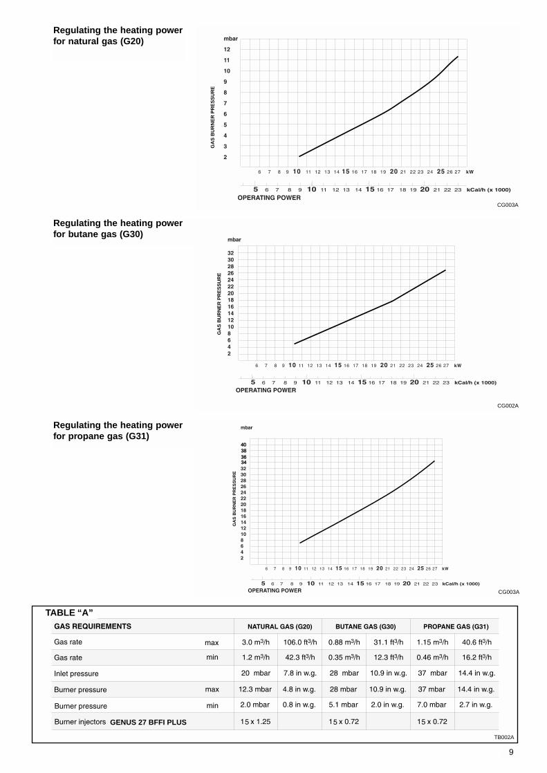
Regulating the heating powerfor natural gas (G20)
34363840
GA
S B
UR
NE
R P
RE
SS
UR
E
Regulating the heating powerfor butane gas (G30)
GA
S B
UR
NE
R P
RE
SS
UR
E
Regulating the heating powerfor propane gas (G31)
GENUS 27 BFFI PLUS
TABLE “A”
TB002A
CG003A
CG002A
CG003A
10
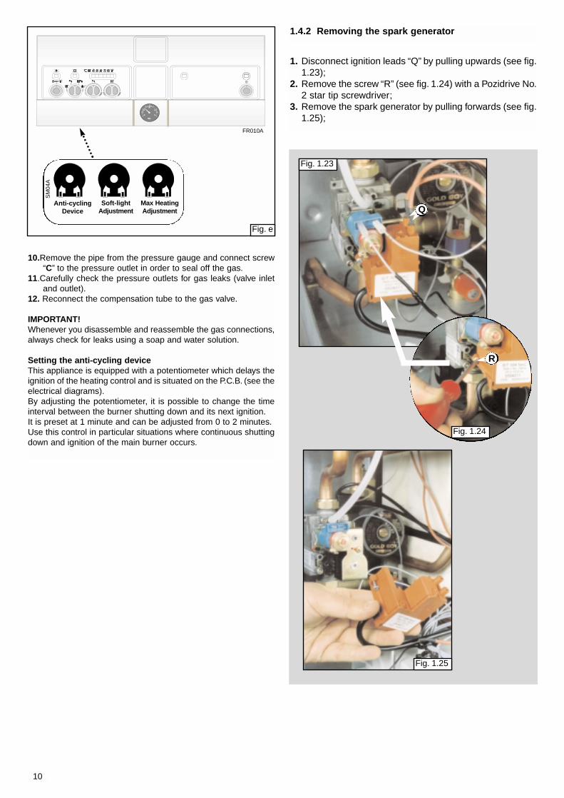
Anti-cyclingDevice
Soft-lightAdjustment
Max HeatingAdjustment
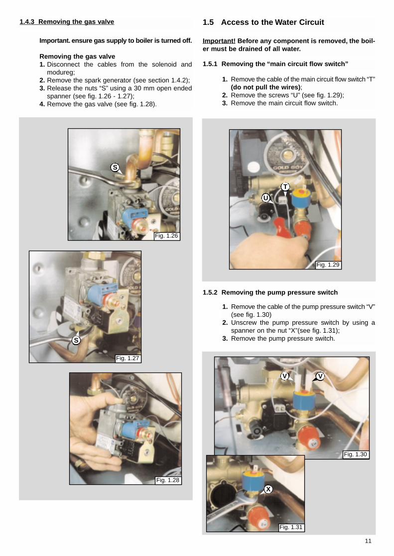
1.4.2 Removing the spark generator
Fig. 1.23
Fig. 1.25
Fig. e
Q
R
1. Disconnect ignition leads “Q” by pulling upwards (see fig.1.23);
2. Remove the screw “R” (see fig. 1.24) with a Pozidrive No.2 star tip screwdriver;
3. Remove the spark generator by pulling forwards (see fig.1.25);
10.Remove the pipe from the pressure gauge and connect screw“C” to the pressure outlet in order to seal off the gas.
11.Carefully check the pressure outlets for gas leaks (valve inletand outlet).
12. Reconnect the compensation tube to the gas valve.
IMPORTANT!Whenever you disassemble and reassemble the gas connections,always check for leaks using a soap and water solution.
Setting the anti-cycling deviceThis appliance is equipped with a potentiometer which delays theignition of the heating control and is situated on the P.C.B. (see theelectrical diagrams).By adjusting the potentiometer, it is possible to change the timeinterval between the burner shutting down and its next ignition.It is preset at 1 minute and can be adjusted from 0 to 2 minutes.Use this control in particular situations where continuous shuttingdown and ignition of the main burner occurs.
Fig. 1.24
FR010A
SM
04A
11
1.5 Access to the Water Circuit
Important! Before any component is removed, the boil-er must be drained of all water.
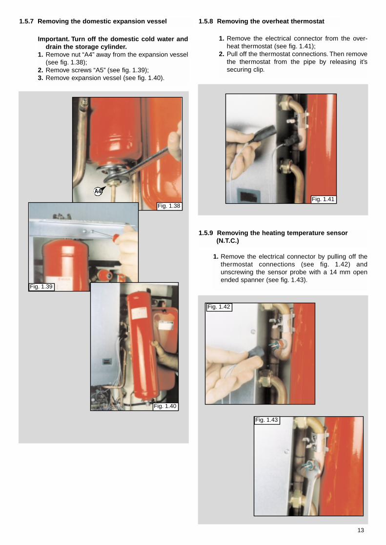
Important. ensure gas supply to boiler is turned off.
Removing the gas valve1. Disconnect the cables from the solenoid and
modureg;2. Remove the spark generator (see section 1.4.2);3. Release the nuts “S” using a 30 mm open ended
spanner (see fig. 1.26 - 1.27);4. Remove the gas valve (see fig. 1.28).
1.4.3 Removing the gas valve
1.5.2 Removing the pump pressure switch
1. Remove the cable of the pump pressure switch “V”(see fig. 1.30)
2. Unscrew the pump pressure switch by using aspanner on the nut “X”(see fig. 1.31);
3. Remove the pump pressure switch.
1.5.1 Removing the “main circuit flow switch”
1. Remove the cable of the main circuit flow switch “T”(do not pull the wires);
2. Remove the screws “U” (see fig. 1.29);3. Remove the main circuit flow switch.
Fig. 1.26
Fig. 1.27
Fig. 1.28
Fig. 1.29
Fig. 1.30
Fig. 1.31
S
S
T
U
V V
X

12
1.5.4 Removing the automatic air vent
1. Remove the automatic air vent “Z” by unscrewing from the pump (see fig. 1.33);
1.5.5 Removing the pump
1.5.6 Removing the pressure gauge
1. Remove electrical connectione “A1”(see fig. 1.34).
2. Disconnected the two nuts “A2” (see fig. 1.34);3. Remove the pump.
1. Remove the pressure gauge cover by pulling (see fig. 1.35);
2. Release coupling “A3” using a 14 mm openended spanner (see fig. 1.36);
3. Push the pressure gauge through the controlpanel from the rear (see fig. 1.37).
1.5.3 Removing the safety valve
1. Remove the pump pressure switch (see section 1.5.2)
2. Loosen nut “Y” disconnect the safety dischargepipework from under the boiler (see fig. 1.32);
3. Remove the valve.
Y
Y
Fig. 1.32
A2
A2
A1
Fig. 1.34
Fig. 1.36
A3
Fig. 1.35
Fig. 1.33
Z
Fig. 1.37
13
Important. Turn off the domestic cold water anddrain the storage cylinder.
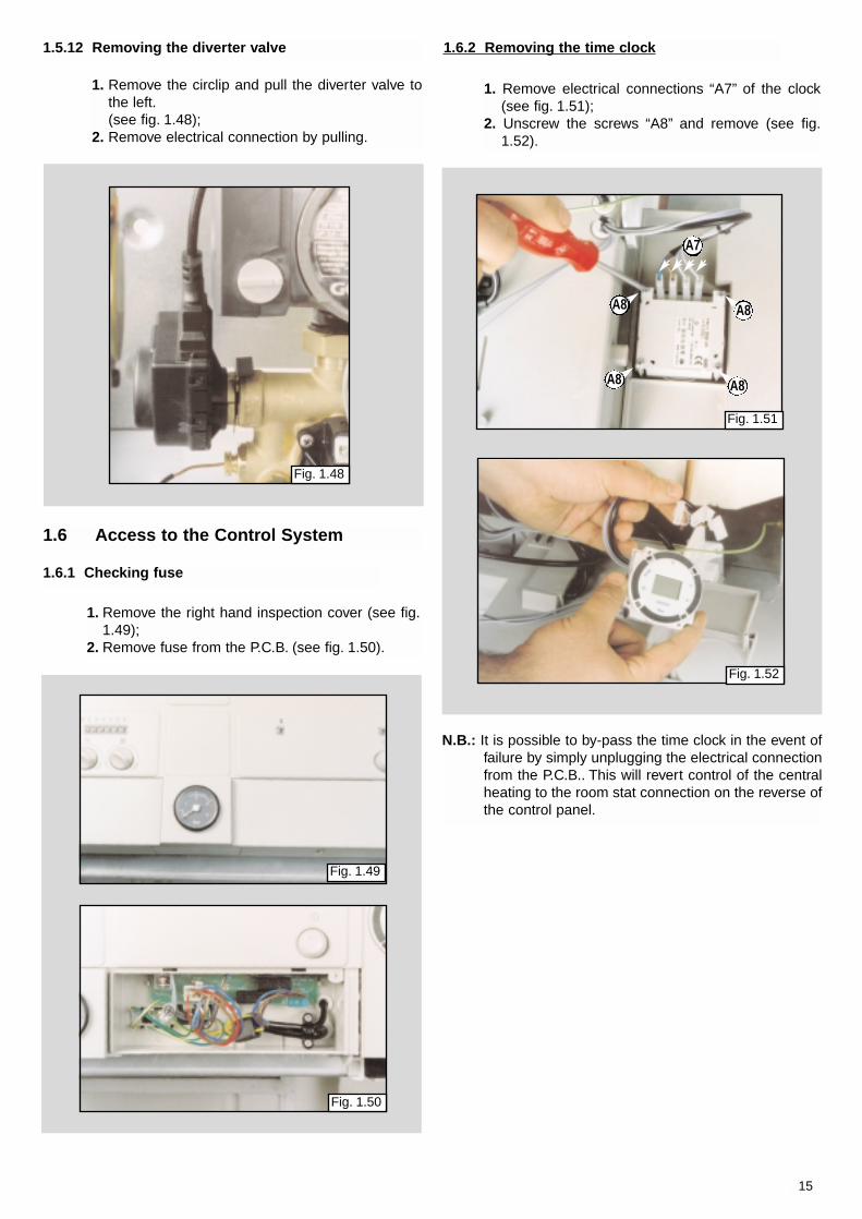
1. Remove nut “A4” away from the expansion vessel(see fig. 1.38);
2. Remove screws “A5” (see fig. 1.39);3. Remove expansion vessel (see fig. 1.40).
1. Remove the electrical connector from the over-heat thermostat (see fig. 1.41);
2. Pull off the thermostat connections. Then removethe thermostat from the pipe by releasing it’ssecuring clip.
1. Remove the electrical connector by pulling off thethermostat connections (see fig. 1.42) andunscrewing the sensor probe with a 14 mm openended spanner (see fig. 1.43).
1.5.7 Removing the domestic expansion vessel 1.5.8 Removing the overheat thermostat
1.5.9 Removing the heating temperature sensor(N.T.C.)
Fig. 1.38
A4
Fig. 1.39
Fig. 1.40
Fig. 1.41
Fig. 1.42
Fig. 1.43

14
1.5.11 Removing the D.H.W. probe1.5.10 Temperature and pressure relief valve
This operation is possible with boiler fully assembled.The D.H.W. probe access, is at the bottom right sideof the boiler:1. Ensure electricity is switched of at main isolator.2. Hold the D.H.W. probe spring and pull downwards
(see fig. 1.46)3. Remove the spring (see fig. 1.47)4. Disconnect the probe;5. Replace with new D.H.W. probe;6. Mount the spring;7. Introduce new probe into its housing pushing
upwards;8. Ensure the probe has reached the end of the
housing pushing firmly again.
1. Ensure electricity is switched off at main isolator;2. Drain domestic water from cylinder;3. Loosen nut “A6” and remove the 1/2” nipple
(see fig. 1.44);4. Remove the valve by unscrewing in an anticlock-
wise direction (see fig. 1.45);
Fig. 1.47
Fig. 1.45
Fig. 1.44
Fig. 1.46
A6
1. Remove the right hand inspection cover (see fig.1.49);
2. Remove fuse from the P.C.B. (see fig. 1.50).
1.6 Access to the Control System
1. Remove electrical connections “A7” of the clock(see fig. 1.51);
2. Unscrew the screws “A8” and remove (see fig.1.52).
Fig. 1.49
Fig. 1.50
Fig. 1.51
Fig. 1.52
N.B.: It is possible to by-pass the time clock in the event offailure by simply unplugging the electrical connectionfrom the P.C.B.. This will revert control of the centralheating to the room stat connection on the reverse ofthe control panel.
1.6.1 Checking fuse
1.6.2 Removing the time clock
A8
A8
A8
A8
A7
15
1.5.12 Removing the diverter valve
1. Remove the circlip and pull the diverter valve tothe left.(see fig. 1.48);
2. Remove electrical connection by pulling.
Fig. 1.48

16
1. Isolate electricity;2. Remove the front cover of the boiler;3. Remove both left and right inspection panels by
remove the screws “A9” (see fig. 1.51);4. Remove the pressure gauge cover;5. Remove the five screws retaining the facia panel;6. Disconnect the connection cable”A10” (see fig.
1.52);7. To remove the 24V P.C.B.: remove the electrical
plug connectors and screws “A11” (see fig. 1.53);8. To remove the 240V P.C.B.: remove the electrical
plug connectors and screws “A12” (see fig. 1.53);9. Replace either P.C.B. in reverse order.
Fig. 1.51
Fig. 1.52
Fig. 1.53
A9 A9
A10
A11
1.6.3 Removing the P.C.B.s
A11 A12
A12
17
PRELIMARY CHECKSMAKE SURE THAT:
ISTHE POWER
L.E.D.ON?
POSTIONOF THE
SELECTOR
NO
NO
ESTAT ED.H.W.Only Mode
NONO
YESYES
YESYES
FUME DISCHARGE FUME DISCHARGE TESTTEST
HEAHEATING ANDTING ANDD.H.M..H.M. MODE MODE
HEAHEATINGTINGONLONLY MODEY MODE
YESYES
NONO
NONO
NONO
YESYES
YESYES
YESYES
1 - Check the fuses2 - Check the power supply cord, plug and outlet3 - Check/replace the power supply P.C.B.
Press theOn / Off Button
D.H.W. ISBEING DRAWN?
D.H.W. ISBEING DRAWN?
FOR BOILERSWITH ELECTRONIC
ANTI-FROST DEVICE:PROTECTION IS ACTIVATED
IF HEATING TEMPIS < 5°C
FOR BOILERSWITH ELECTRONIC
ANTI-FROST DEVICE:PROTECTION IS ACTIVATED
IF HEATING TEMPIS < 5°C
MUSTTIME CLOCK
AND/OR ROOMTHERMOSTAT
BE ACTIVATED?
A
1 - There is sufficient water in the system2 - The gas is turned on 3 - The electrical supply is turned on
1 - Check/reset system pressure2 - Check/restore gas supply3 - Check/replace short- circuited heating probe4 - Check/replace siezed pump
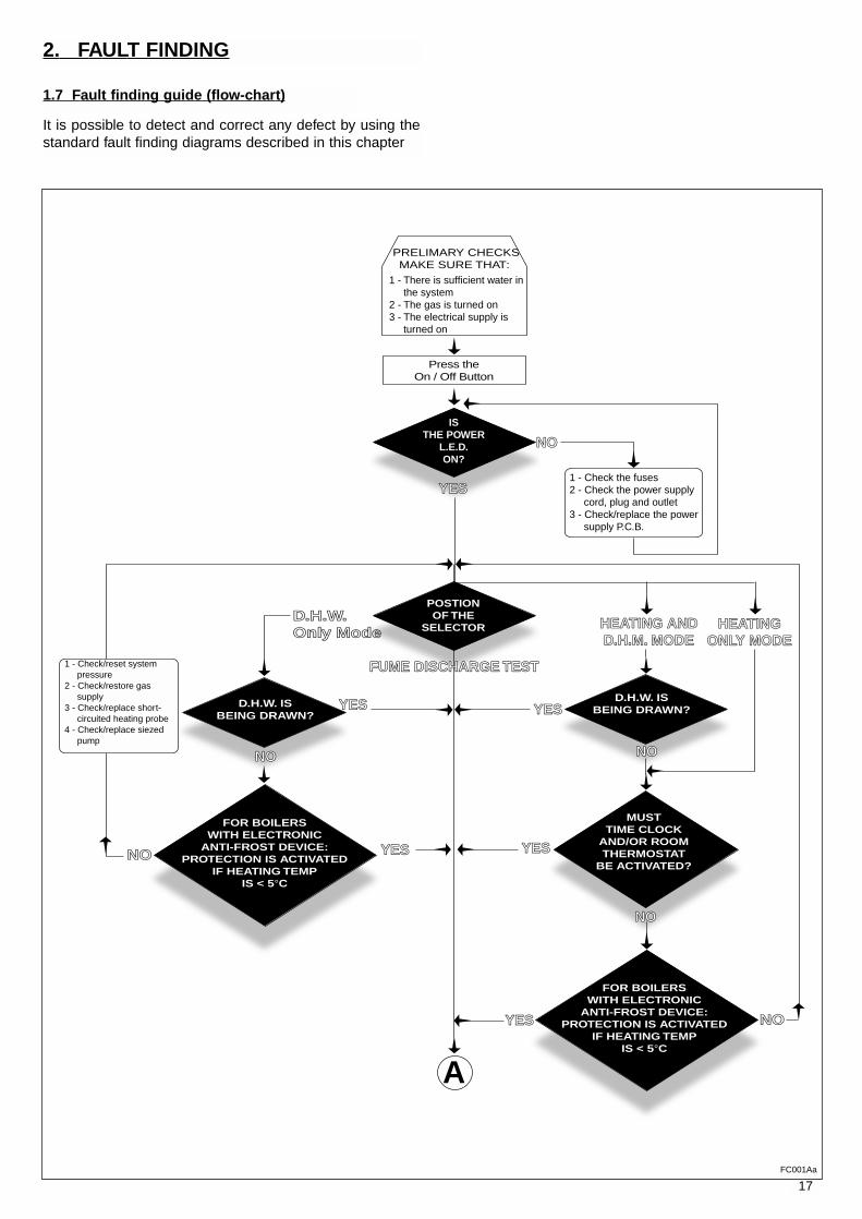
It is possible to detect and correct any defect by using thestandard fault finding diagrams described in this chapter
1.7 Fault finding guide (flow-chart)
2. FAULT FINDING
FC001Aa
18
DOES THECIRCULATION PUMP
COME ON?
YES
NO
NO
NO
YES
YES
POWER TOTHE PUMP?
DOES THEINSUFFICIENT WATER
INDICATOR LIGHT COMEON? (within
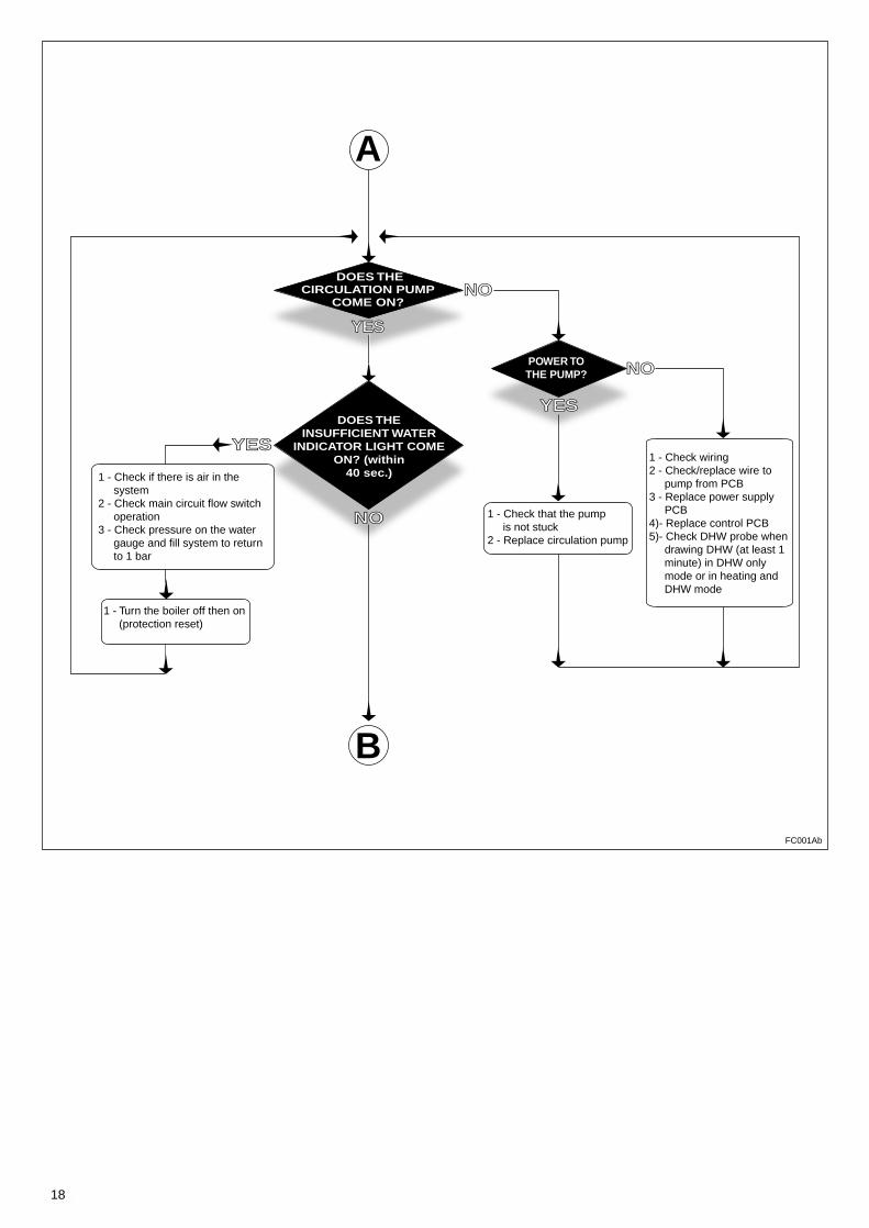
40 sec.)1 - Check if there is air in the system2 - Check main circuit flow switch operation3 - Check pressure on the water gauge and fill system to return to 1 bar
1 - Turn the boiler off then on (protection reset)
1 - Check that the pump is not stuck2 - Replace circulation pump
1 - Check wiring2 - Check/replace wire to pump from PCB3 - Replace power supply PCB4)- Replace control PCB5)- Check DHW probe when drawing DHW (at least 1 minute) in DHW only mode or in heating and DHW mode
A
B
FC001Ab
19
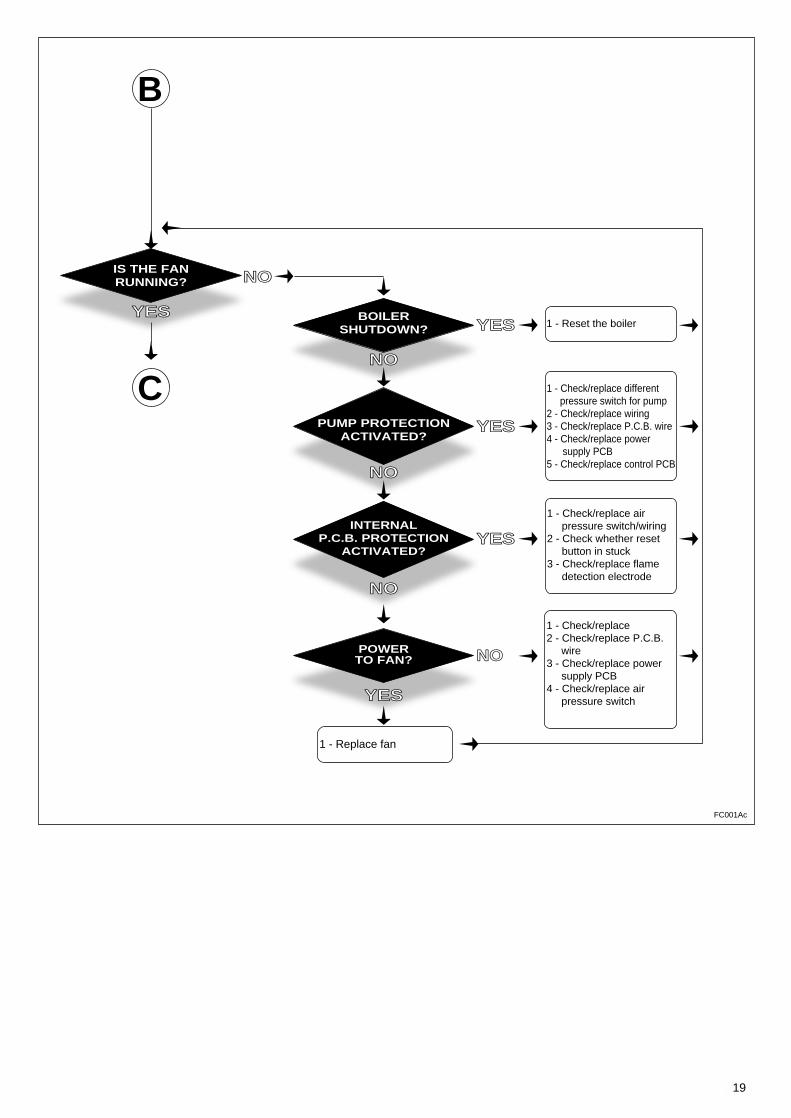
IS THE FANRUNNING?
BOILERSHUTDOWN?
POWERTO FAN?
NO
YES
YES
YES
NO
YES
NO
NO
NO
YES
1 - Check/replace different pressure switch for pump2 - Check/replace wiring3 - Check/replace P.C.B. wire4 - Check/replace power supply PCB5 - Check/replace control PCB
1 - Check/replace air pressure switch/wiring2 - Check whether reset button in stuck3 - Check/replace flame detection electrode
1 - Check/replace2 - Check/replace P.C.B. wire3 - Check/replace power supply PCB4 - Check/replace air pressure switch
1 - Replace fan
1 - Reset the boiler
PUMP PROTECTIONACTIVATED?
INTERNALP.C.B. PROTECTION
ACTIVATED?
B
C
FC001Ac

20
IS THE BURNERALIGHT?
YES
NO
YES
YES
YES
NO
NO
NO
YES
1 - Check/replace igniter plugs2 - Check wiring3 - Check spark generator4 - Check small wire5 - Check power supply PCB6 - Check control PCB
1 - Check if flame strikes detection electrode2 - Check soft-light gas pressure3 - Check/replace detection electrode4 - Check the power P.C.B. 5 - Check the control P.C.B.
1 - Check supply of gas to gas valve2 - Check power supply P.C.B.3 - Check control P.C.B.4 - Check modureg
Shutdown L.E.D. offRestart of the fan
IS THEAIR PRESSURE SWITCH
ACTIVATED?
IS FLUEDISCHARGENORMAL?
HAS THEBOILER SAFETY
SHUTDOWN BEENACTIVATED?
WAS THERESET SWITCH
PRESSED?
NO
1 - Check flue discharge2 - Check venturi & small pipes3 - Check wire for air press.switch4 - Check/replace air press.switch5 - Check/replace PCB wire6 - Check/replace power PCB7 - Checl/replace control PCB
C
D
FC001Ad
21
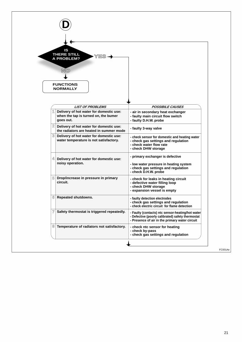
ISTHERE STILLA PROBLEM?
FUNCTIONSNORMALLY
NO
YES
LIST OF PROBLEMS POSSIBILE CAUSES1
2
3
4
5
6
7
8
D
Delivery of hot water for domestic use:when the tap is turned on, the bumergoes out.
Delivery of hot water for domestic use:the radiators are heated in summer mode
Delivery of hot water for domestic use:water temperature is not satisfactory.
Delivery of hot water for domestic use:noisy operation.
Drop/increase in pressure in primarycircuit.
Repeated shutdowns.
Safety thermostat is triggered repeatedly.
Temperature of radiators not satisfactory.
- air in secondary heat exchanger- faulty main circuit flow switch- faulty D.H.W. probe
- faulty 3-way valve
- check sensor for domestic and heating water- check gas settings and regulation- check water flow rate- check DHW storage
- primary exchanger is defective
- low water pressure in heating system - check gas settings and regulation- check D.H.W. probe
- check for leaks in heating circuit- defective water filling loop- check DHW storage- expansion vessel is empty
- faulty detection electrodes- check gas settings and regulation- check electric circuit for flame detection
- Faulty (contacts) ntc sensor-heating/hot water- Defective (poorly calibrated) safety thermostat- Presence of air in the primary water circuit
- check ntc sensor for heating- check by-pass- check gas settings and regulation
FC001Ae
22
3. ELECTRIC DIAGRAMS
Legend:
AT = High Voltage P.C.B.BT = Low Voltage P.C.B.
A = Remote Connector KitB = Flame Failure L.E.D.C = Insufficient Water Pressure L.E.D.D = Water Temperature Indicator L.E.D.sE = Overheat Thermostat Warning L.E.D.F = System Reset ButtonG = Selector Knob for Operating ModeH = Domestic Hot Water Temp. AdjustmentI = Central Heating Temp. AdjustmentJ = Connector for Time ClockK = Connector for Total Check SystemL = Selector for Local/Remote ControlM = Anti-cycling Device Adjustment for HeatingN = Soft-light AdjustmentO = Max Heating Temperature Adjustment Q = On/Off L.E.D.R = On/Off SwitchS = Interface Wire for P.C.B.sT = Relay Motorised ValveU = Ignitor RelayV = Gas Valve RelayW = Fan RelayX = Circulation Pump Relay
Y = Selector TCS2Z = Link for Continuous Pump Run
A01 = Air Pressure SwitchA02 = FanA03 = Gas ValveA05 = Motorised ValveA06 = Circulation PumpA07 = Flame DetectorA08 = Earth Terminal
B01 = Over Heat ThermostatB02 = External ThermostatB03 = Gas Valve ModulatorB04 = D.H.W. Probe Sensor Cylinder B05 = Heating SensorB06 = Pressure Switch for Heating CircuitB07 = Pump pressure switch
ColoursGry = GreyRd = RedBl = BlueGrn/Yll = Yellow/Green Wh = WhiteBrn = BrownBlk = BlackWh/Rd = White/Red
T
D.H.W.Heating+ D.H.W.
Flue Testoperatingmodes
Heating
AT
BT
SE003A
23
ER
2000
2100
2000
1001
- 2 -
1
6
2
49
40
41
46
47
131
94
40
484950
4344
33 34 35 36 37
128
39
9
6463656667
119
6557
117
121
5960616263
71
70 69
10
14
4
3
21 22 31 322823 2415
115
116
72 74
6
11
9112
15
6
92
87
90
134
135
55
56
52
53
51
58
126
127
129
130
106
107
6
6
102
81
2
73
80
76
7779
78
109
30
28
20
45
114
132
122
113
125
112
111
113
111
123
124
68
304
301302302301 303
304
305307
112
304306
115
18
13
38
133
29
40
84
89
88
6
88
103
8
5
76
9
6
82
8
8685
8
83
93
94
75
54
99
10022
272625
22
22
118
120
101
42
2696
2895
22
97
26
2615
1617
19
98
105
104
110
108
Code 998799
363
361
362
311
313
312
Code 573127
371
372
373374
375
Code 998099
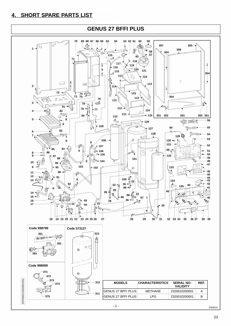
MODELS CHARACTERISTICS SERIAL NO:VALIDITY
REF.
GENUS 27 BFFI PLUS METHANE 2320010200001 A
GENUS 27 BFFI PLUS LPG 2320010200001 B
4. SHORT SPARE PARTS LIST
GENUS 27 BFFI PLUS
ES001A
24
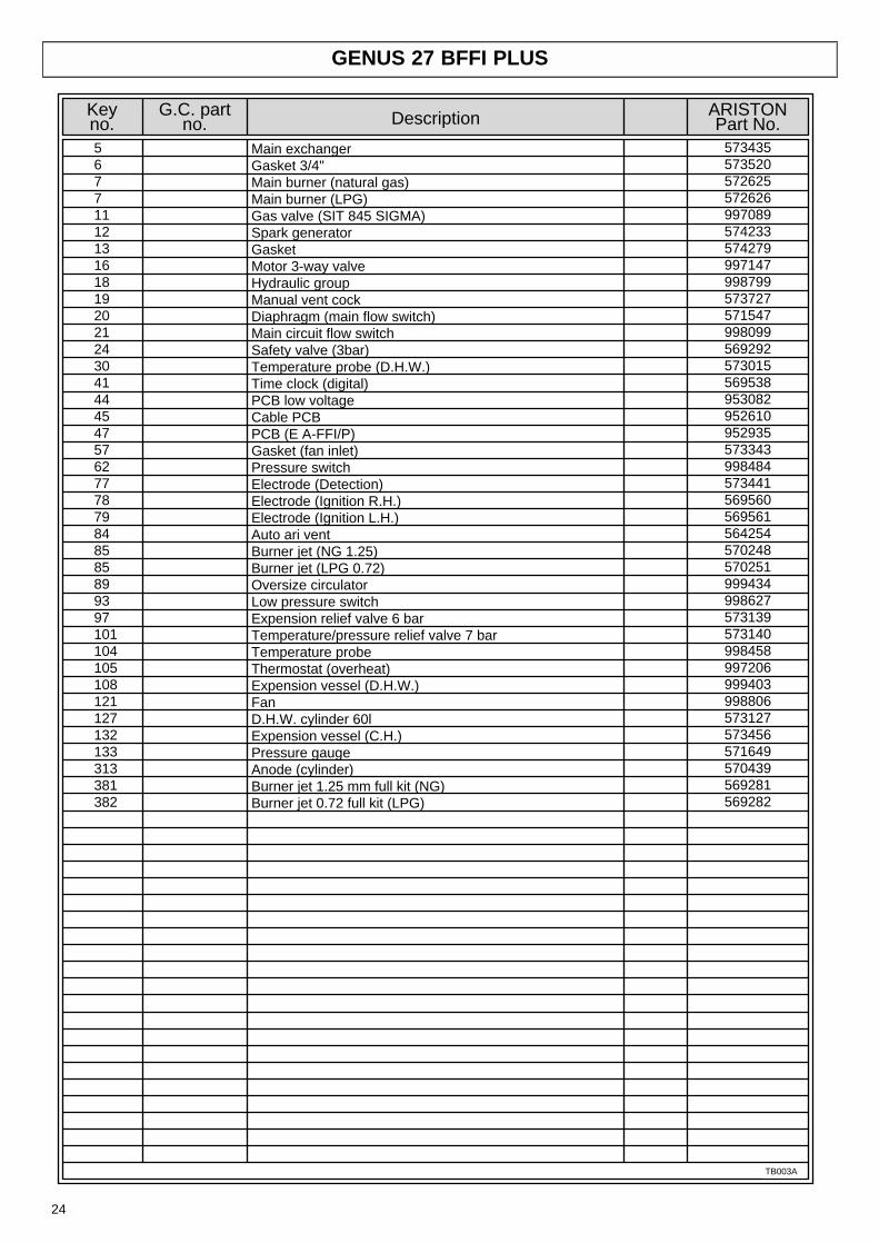
GENUS 27 BFFI PLUS
573435573520572625572626997089574233574279997147998799573727571547998099569292573015569538953082952610952935573343998484573441569560569561564254570248570251999434998627573139573140998458997206999403998806573127573456571649570439569281569282
Keyno.
G.C. partno.
ARISTONPart No.Description
379816 Main exchangerGasket 3/4"Main burner (natural gas)Main burner (LPG)Gas valve (SIT 845 SIGMA)Spark generatorGasketMotor 3-way valveHydraulic groupManual vent cockDiaphragm (main flow switch)Main circuit flow switchSafety valve (3bar)Temperature probe (D.H.W.)Time clock (digital)PCB low voltageCable PCBPCB (E A-FFI/P)Gasket (fan inlet)Pressure switchElectrode (Detection)Electrode (Ignition R.H.)Electrode (Ignition L.H.)Auto ari ventBurner jet (NG 1.25)Burner jet (LPG 0.72)Oversize circulatorLow pressure switchExpension relief valve 6 barTemperature/pressure relief valve 7 barTemperature probeThermostat (overheat)Expension vessel (D.H.W.)FanD.H.W. cylinder 60lExpension vessel (C.H.)Pressure gaugeAnode (cylinder)Burner jet 1.25 mm full kit (NG)Burner jet 0.72 full kit (LPG)
1
1111
1111111111111
11
1
1111
111111111111
567711121316181920212430414445475762777879848585899397101104105108121127132133313381382
TB003A

23 99 84 1518 111
Manufacturer: Merloni TermoSanitari SpA - Italy
Commercial subsidiary: MTS (GB) LIMITEDMTS BuildingHughenden AvenueHigh WycombeBucks HP13 5FT
Telephone: (01494) 755600
Fax: (01494) 459775
Internet: http://www.mtsgb.ltd.uk
E-mail: [email protected]
Technical Service Hot Line: (01494) 539579
403
UsersManual

2 403
TABLE OF CONTENTS
1) GENERAL INFORMATION page 32) OPERATING INSTRUCTIONS page 43) TIME CLOCK page 74) USEFUL INFORMATION AND TROUBLESHOOTING page 10
IMPORTANT Please read this manual carefully.
For additional information, please consult the “Installation and Servicing Instructions.”
Please ensure manuals provided are kept with the appliance so that they can be used by the end-user, installer or our authorised engineer.
Dear Customer,
Thank you for choosing an ARISTON boiler.We guarantee that your boiler is areliable and technically sound product.This User’s Manual provides detailed instructions and recommendations for proper installation,use and maintenance.Remember to keep this manual in a safe place for future reference i.e. by the gas meter.Your local MTS Servicing Centre is at your complete disposal for all requirements.
MTS (GB) Limited
Every attempt has been made to avoid errors ofany kind
in this User’s Manual, the Management invites customers to inform
of any inaccuracies which they may find.This will help to improve our service
The guarantee on this appliance is validfor 12 months from the first day of
installation.
Repairs to the electric, hydraulic or gascircuits may be carried out only by yourlocal authorised MTS Servicing Centre.

3403
CONTROL PANEL
LegendA) Ignition Lockout Reset Button/Safety (Overheat)Thermostat ResetB) Ignition Lockout L.E.D.C) Selector Knob for Summer/Winter/Flue Analysis ModesD) Low System Water Level L.E.D.E) Temperature Adjustment Knob for Domestic Hot WaterF) Heating System ThermometerG) Safety (Overheat)Thermostat Intervention L.E.D.H) Adjustment Knob for Heating TemperatureI) On/Off L.E.D.L) On/Off SwitchO) Heating System Pressure Gauge
MTS (GB) Limited support the initiative.Your installer will giveyou, and show you how to use, a logbook which will give you importantinformation about your boiler, and heating system. Please have thislogbook to hand whenever you contact a service engineer or us.All CORGI Registered Installers carry a CORGI ID card, and havea registration number. Both should be recorded in your boilerLogbook. You can check your installer is CORGI registered bycalling CORGI direct on :- (01256) 372300.
This is a combined appliance for the production of central heating(C.H.) and domestic hot water (D.H.W.). This appliance must be usedonly for the purpose for which it is designed. The manufacturerdeclines all liability for damage caused by improper or negligent use.Do not allow children or inexperienced persons to use the appliancewithout supervision.If you smell gas in the room, do not turn on light switches, use thetelephone or any other object which might cause sparks.Open doors and windows immediately to ventilate the room.Shut the gas mains tap (on the gas meter) or the valve of the gascylinder and call your Gas Supplier immediately.If you are going away for a long period of time, remember to shut themains gas tap or the gas cylinder valve.
Before any intervention within the boiler it is first necessary to cutoff the electrical power supply by turning the external switch to“OFF”.This manual may be kept in the front panel of the boiler.
1. GENERAL INFORMATION
FR004A
4 403
CAUTIONInstallation, start-up, adjustments and maintenance must beperformed by a competent person only, in accordance with thecurrent Gas Safety (Installation & Use) Regulations and theinstructions provided. Improper installation may cause damage orinjury to individuals, animals and personal property, for which themanufacturer will not be held liable.To ensure efficient and safe operation it is recommended that theboiler is serviced annually by a competent person.If it is known or suspected that a fault exists on the appliance, itmust not be used until the fault has been corrected by a competentperson.
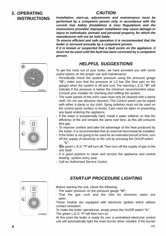
HELPFUL SUGGESTIONSTo get the most out of your boiler, we have provided you with someuseful advice on the proper use and maintenance:- Periodically check the system pressure using the pressure guage
“O”, make sure that the pressure at 1.5 bar (the blue part on thegauge) when the system is off and cool. The warning L.E.D. “D” willindicate if the pressure is below the minimum recommended value.Consult your installer for checking and refilling the system.
- The outer panels of the unit's case must only be cleaned with a dampcloth. Do not use abrasive cleaners. The Control panel can be wipedwith either a damp or dry cloth. Spray polishes must not be used onthe control panel surface or knobs. Care must be taken in preventingany liquid entering the appliance.
- If the water is exceptionally hard, install a water softener so that theefficiency of the unit remains the same over time, as this will consumeless gas.
- To improve comfort and take full advantage of the heat produced bythe boiler, it is recommended that an external thermostat be installed.
- If the boiler is not going to be used for an extended period of time, turnoff the supply of electricity to the unit by pressing the On/Off switch
“L”.- The green L.E.D. “I” will turn off. Then turn off the supply of gas to the
unit itself.- It is good practice to clean and service the appliance and central
heating system every year.- Call an Authorised Service Centre.
O
I
I
IL
2. OPERATING INSTRUCTIONS
START-UP PROCEDURE LIGHTING
Before starting the unit, check the following:· The water pressure on the pressure gauge “O”;· That the gas cock and the inlet for domestic water are
open.These models are equipped with electronic ignition which utilisescontact ionisation.To make the boiler operational, simply press the On/Off switch “L”.The green L.E.D. “I” will then turn on.At this point the boiler is ready for use: a centralised electronic controlunit will automatically light the main burner when needed. If the burner
UT001A
UT008Aa
I
IL
UT008Aa

5403
C
H
°C 40 50 60 70 80F
B
A
does not light within the pre-set safety time limit, the red “B” L.E.D. willlight up. To reset the ignition system, the reset button “A” must bepressed. Should the system fail to light a second time, check to makesure that the gas cock is open. If the problem persists, contact one ofour Authorised Service Centres for assistance.
WINTER AND SUMMER OPERATING MODES
The boiler is fitted with a selector knob “C” which allows you to switchbetween winter < > and summer < > and also heating only <
> operating modes and vice versa. When the knob is set to <>, the boiler can serve the dual purpose of providing heat and/or hotwater for domestic use.The supply of hot water for domestic use always takes precedenceover heating. When the knob is set to < >, the boiler cuts out theheating system and only provides hot water for domestic use (whenneeded).
TURNING ON THE CENTRAL HEATING
Installation without a room thermostat :- Turn on the power supply to the boiler by pressing the
On/Off switch “L”; the green L.E.D. “I” will then turn on;
- Turn the “C” selector knob to < > or < > (in this position nodomestic hot water is produced);
- Regulate the temperature of the water in the boiler by turning the “H”knob. The temperature can vary between 42°C and about 82°C;
- Check the boiler temperature on the thermometer with the yellowL.E.D.s “F”. With this type of installation, the ambient temperaturedoes not influence the operation of the boiler and the circulationpump always remains in operation.
UT008Ab
UT008Ac
C
UT008Ac
UT008Ad UT008Ae
I
IL
UT008Aa
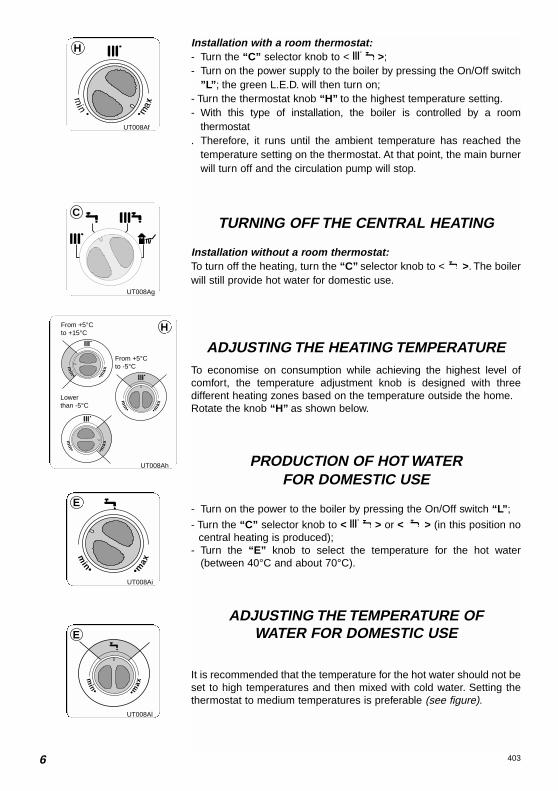
6 403
Installation with a room thermostat:- Turn the “C” selector knob to < >;- Turn on the power supply to the boiler by pressing the On/Off switch
”L”; the green L.E.D. will then turn on;- Turn the thermostat knob “H” to the highest temperature setting.- With this type of installation, the boiler is controlled by a room
thermostat. Therefore, it runs until the ambient temperature has reached the
temperature setting on the thermostat. At that point, the main burnerwill turn off and the circulation pump will stop.
TURNING OFF THE CENTRAL HEATING
Installation without a room thermostat:To turn off the heating, turn the “C” selector knob to < >. The boilerwill still provide hot water for domestic use.
ADJUSTING THE HEATING TEMPERATURETo economise on consumption while achieving the highest level ofcomfort, the temperature adjustment knob is designed with threedifferent heating zones based on the temperature outside the home.Rotate the knob “H” as shown below.
PRODUCTION OF HOT WATERFOR DOMESTIC USE
- Turn on the power to the boiler by pressing the On/Off switch “L”;
- Turn the “C” selector knob to < > or < > (in this position nocentral heating is produced);
- Turn the “E” knob to select the temperature for the hot water(between 40°C and about 70°C).
ADJUSTING THE TEMPERATURE OFWATER FOR DOMESTIC USE
It is recommended that the temperature for the hot water should not beset to high temperatures and then mixed with cold water. Setting thethermostat to medium temperatures is preferable (see figure).
min• •m
ax
min• •m
ax
min• •m
ax
From +5°Cto +15°C
Lowerthan -5°C
From +5°Cto -5°C
H
H
UT008Af
C
UT008Ag
min• •m
ax
E
UT008Ai
min• •m
ax
E
UT008Al
UT008Ah
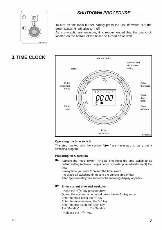
7403
Operating the time switchThe step marked with the symbol “ ” are necessary to carry out aswitching program.
Preparing for Operation
Activate the “Res” switch (=RESET) to reset the time switch to itsdefault setting (activate using a pencil or similar pointed instrument). Dothis:- every time you wish to “reset” the time switch- to erase all switching times and the current time of day.After approximately two seconds the following display appears:
Enter current time and weekday
- Keep the “ ” key pressed downDuring the summer time period press the +/- 1h key once.Enter the hour using the “h” keyEnter the minutes using the “m” keyEnter the day using the “Day” key1 = “Monday”..............7 = Sunday
- Release the “ ” key.
Pro
g. hm
Day
Manual switch
Summer andwinter timesettingReset
Enterweekday/s
Enterthe hours
Week-daysflash
Enterminutes
Enterswitching
times
Imputtime
3. TIME CLOCK
SHUTDOWN PROCEDURE
To turn off the main burner, simply press the On/Off switch “L”; thegreen L.E.D. “I” will also turn off.As a precautionary measure, it is recommended that the gas cocklocated on the bottom of the boiler be turned off as well.
I
IL
UT008Aa
UT008Am
Input

8 403
Automatic Manual ContinuousOperation Operation Operation
The switching If the current You can onlytimes corres- switching mode is return to automaticpond to the changed manually, mode from theprogram the next switching continuously-ONentered. time will be and continuously-
carried out auto- OFF switchingmatically again modes byaccording to the pressing the " "entered switching key.program.
= ON = ON = Continuously ON
= OFF = OFF = Continuously OFF
Entering the switching timesYou have 20 memory Iocations available. Each switching time takes upone memory location.Keep pressing the “Prog” key until a free memory location is shown inthe display “– –:– –”.
Programme ON or OFF with the “ ” key:“ ”= OFF; “ ”= ONEnter the hour using “h”Enter the minutes using “m”If a switching command is to be carried out every day (1 2 3 4 5 6 7)
then store using the “ ” key, otherwise select the day(s) it is to becarried out by using the “Day” key.
When the day seIection is left bIank, the programmed switchinginstruction operates at the same time every day1 2 3 4 5 6 = Monday – Saturday1 2 3 4 5 = Monday – Friday6 7 =Saturday – Sunday
Selection of single days: 1 = Mon. .............. 2 =Tues.
Save the switching time with the “ ” key.The time switch enters the automatic operating mode and displays thecurrent time of day.Begin any further entry of a switching time with the “Prog” switch. Ifyour entry is incomplete, the segments not yet selected will blink in thedisplay. After programming is completed, and you return the time clock
to the current time display with the “ ” key, the time clock will notactivate any switching instruction required for the current time.You may
need to manually select the desired switching state with the “ ”key. Thereafter, as the unit encounters further switching instructions inthe memory in real time, it will correctly activate all subsequentswitching instructions.
Manual Override Switch “ ”
With the “ ” you can change the current setting at any time. Theswitching program already entered is not altered.
UT008An
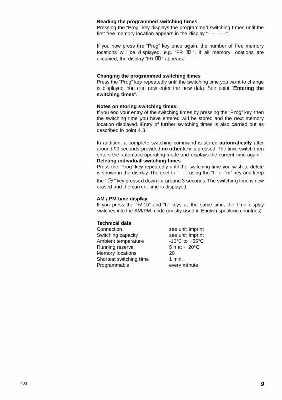
Reading the programmed switching timesPressing the “Prog” key displays the programmed switching times until thefirst free memory location appears in the display “– – : – –”.
If you now press the “Prog” key once again, the number of free memoryIocations will be displayed, e.g. “FR 1188 ”. If all memory locations areoccupied, the display “FR 0000 ” appears.
Changing the programmed switching timesPress the “Prog” key repeatedly until the switching time you want to changeis displayed. You can now enter the new data. See point “Entering theswitching times”.
Notes on storing switching times:If you end your entry of the switching times by pressing the “Prog” key, thenthe switching time you have entered will be stored and the next memorylocation displayed. Entry of further switching times is also carried out asdescribed in point 4.3.
In addition, a complete switching command is stored automatically afteraround 90 seconds provided no other key is pressed. The time switch thenenters the automatic operating mode and displays the current time again.Deleting individual switching timesPress the “Prog” key repeatedly until the switching time you wish to deleteis shown in the display. Then set to “– –” using the “h” or “m” key and keep
the “ ” key pressed down for around 3 seconds. The switching time is nowerased and the current time is displayed.
AM / PM time display If you press the “+/-1h” and “h” keys at the same time, the time displayswitches into the AM/PM mode (mostly used in English-speaking countries).
Technical dataConnection see unit imprintSwitching capacity see unit imprintAmbient temperature -10°C to +55°CRunning reserve 5 h at + 20°CMemory Iocations 20Shortest switching time 1 min.Programmable every minute
9403
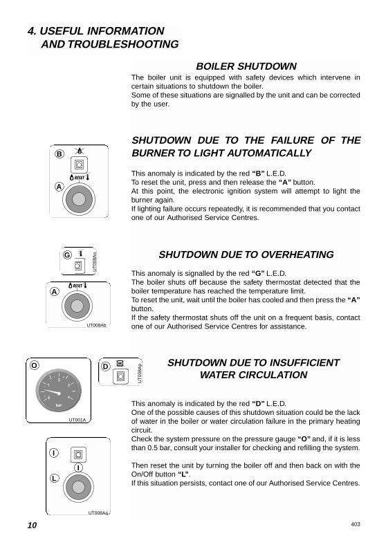
10 403
4. USEFUL INFORMATION AND TROUBLESHOOTING
B
A
G
BOILER SHUTDOWNThe boiler unit is equipped with safety devices which intervene incertain situations to shutdown the boiler.Some of these situations are signalled by the unit and can be correctedby the user.
SHUTDOWN DUE TO THE FAILURE OF THEBURNER TO LIGHT AUTOMATICALLY
This anomaly is indicated by the red “B” L.E.D.To reset the unit, press and then release the “A” button.At this point, the electronic ignition system will attempt to light theburner again.If lighting failure occurs repeatedly, it is recommended that you contactone of our Authorised Service Centres.
SHUTDOWN DUE TO OVERHEATING
This anomaly is signalled by the red “G” L.E.D.The boiler shuts off because the safety thermostat detected that theboiler temperature has reached the temperature limit.To reset the unit, wait until the boiler has cooled and then press the “A”button.If the safety thermostat shuts off the unit on a frequent basis, contactone of our Authorised Service Centres for assistance.
SHUTDOWN DUE TO INSUFFICIENTWATER CIRCULATION
This anomaly is indicated by the red “D” L.E.D.One of the possible causes of this shutdown situation could be the lackof water in the boiler or water circulation failure in the primary heatingcircuit.Check the system pressure on the pressure gauge “O” and, if it is lessthan 0.5 bar, consult your installer for checking and refilling the system.
Then reset the unit by turning the boiler off and then back on with theOn/Off button “L”.If this situation persists, contact one of our Authorised Service Centres.
I
IL
UT008Aa
O
UT001A
D
UT
008A
p
A
UT008Ab
UT
008A
o

11403
FLUE TEST FEATURE(only for authorised personnel)
The “C” Summer/Winter/Flue Test selector knob can be set to < > tobypass temperature adjustment on the heating circuit for the purpose ofanalysing the fumes produced by combustion.To access this mode, open a water tap or taps so that the flow rate isno less than 8 litres per minute.Then press the “C” selector knob in and turn it from < > or < >to the < >.
WARNING!The flue test feature eliminates the slow-light feature.This mode must only be selected by a qualified service engineer.
C
UT008Aq

Manufacturer: Merloni TermoSanitari SpA - Italy
Commercial subsidiary: MTS (GB) LIMITEDMTS BuildingHughenden AvenueHigh WycombeBucks HP13 5FT
Telephone: (01494) 755600
Fax: (01494) 459775
Internet: http://www.mtsgb.ltd.uk
E-mail: [email protected]
Technical Service Hot Line: (01494) 539579
Co
d.
2399
8415
1700
0