Embed Size (px)
Citation preview
Arkansas Northeastern College
REFERENCE STANDARDS 27 01 00 - 1
SECTION 27 01 00 - REFERENCE STANDARDS
PART 1 - GENERAL
1.1 DESCRIPTION
A. Telecommunications systems shall be provided as indicated on drawings and as called for hereinafter.
1.2 REFERENCE STANDARDS
A. Arkansas Northeast College OIT standards
B. BICSI TDMM current edition (Telecommunications Distribution Methods Manual).
C. ANSI/NECA/BICSCI-568, Standard for Installing Commercial Building Telecommunications Cable.
D. ANSI/TIA 569-C, Pathways and Spaces.
E. ANSI/TIA 568-C.0, Generic Telecommunications for Customer Premises Standard Series
i. 568-C.1 Commercial Building Cabling
ii. 568-C.2 Copper Cabling Components
iii. 568-C.3 Fiber Cabling Components
iv. 568-C.4 Coax Cabling Components
F. ANSI/TIA 606-B, Addendum 1, Administration Standard for Commercial Telecommunications Infrastructure.
G. ANSI J-STD-607-B, Commercial Building Grounding (Earthing) and Bonding Requirements for Telecommunications.
H. ANSI/TIA 758-B, Customer owned Outside Plant Telecommunications Cabling Standard
I. ANSI/TIA-526, 7&14, Telecommunications Measurements of Optical Fiber Single and Multi Mode Power Loss
J. ANSI/TIA Building Automation Systems Cabling Standard for Commercial Buildings
K. ANSI/TIA 310-D, Cabinets, Racks, Panels, and Associated Equipment.
L. FCC Part 68, Connection of Terminal Equipment to the Telephone Network.
M. ADA of 2010 and Telecommunications Act of 1996, Physically Impaired and Accessibility.
N. IEEE 802-2002, Standard for Local and Metropolitan Networks: Overview and Architecture.
O. IEEE 802.11ax Wireless LAN’s
P. NFPA 70, National Electrical Code (2014).
Arkansas Northeast College
REFERENCE STANDARDS 27 01 00 - 2
Q. NFPA-76, Recommended Practice for Fire Protection of Telecommunications Facilities.
R. NFPA 101, Life Safety Code.
S. ETA Electronic Technician Association Fiber Optics Installer
T. FOA Fiber Optics Association Certified Fiber Optics Technician
U. ANSI/SCTE 77 Underground Enclosure Integrity
PART 2 - PRODUCTS (NOT USED)
PART 3 - EXECUTION (NOT USED)
END OF SECTION 27 01 00
Arkansas Northeast College
Telecommunications Grounding & Bonding Secction 270526‐1
Section 27 05 26 Telecommunications Grounding & Bonding
PART 1: GENERAL
1.1 SCOPE OF WORK
A. Work covered by this Section shall consist of furnishing labor, equipment, supplies, materials, tools, and testing unless otherwise specified, and in performing the following operations recognized as necessary for the installation, termination, and labeling of grounding and bonding infrastructure as described on the Drawings and/or required by these specifications.
1.2 REFERENCE
A. IEEE C2-2007 National Electrical Safely Code
B. ANSI/TIA-607-B-2011 Commercial Building Grounding and Bonding Requirements for Telecommunications
C. NFPA 70™-2011 National Electrical Code
D. NFPA 70E*-2004 Standard for Electrical Safely in the Workplace
E. ANSI/NECA/BICSI-607-2011 Telecommunications Bonding and Grounding Planning and Installation Methods for Commercial Buildings
F. UL 467 Standard for Grounding and Bonding Equipment
G. Telcordia GR-63-CORE, NEBS Requirements: Physical Protection.
H. Telcordia GR-487-CORE, Electronic Equipment Cabinets.
I. See SECTION27.01.00 Reference Standards
J. See SECTION27.05.53 Administration/Labeling
K. See SECTION27.05.29 Hangers and supports
1.3 QUALIFICATIONS
A. Products specified in this Section shall be manufactured by a company with a minimum of three years’ documented experience specializing in manufacturing such products.
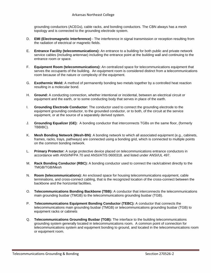
1.4 DEFINITIONS
A. Backbone: A facility (e.g. pathway, cable or conductors) between telecommunications rooms, or floor distribution terminals, the entrance facilities, and the equipment rooms within or between buildings.
B. Bonding: The permanent joining of metallic parts to form an electrically conductive path that will assure electrical continuity and the capacity to conduct safely any current likely to be imposed.
C. Common Bonding Network (CBN): The principal means for effecting bonding and grounding inside a telecommunication building. It is the set of metallic components that are intentionally or incidentally interconnected to form the principal bonding network (BN) in a building. These components include structural steel or reinforcing rods, plumbing, alternating current (ac) power conduit, ac equipment
Arkansas Northeast College
Telecommunications Grounding & Bonding Secction 270526‐2
grounding conductors (ACEGs), cable racks, and bonding conductors. The CBN always has a mesh topology and is connected to the grounding electrode system.
D. EMI (Electromagnetic Interference) - The interference in signal transmission or reception resulting from the radiation of electrical or magnetic fields.
E. Entrance Facility (telecommunications): An entrance to a building for both public and private network service cables (including antennae) including the entrance point at the building wall and continuing to the entrance room or space.
F. Equipment Room (telecommunications): An centralized space for telecommunications equipment that serves the occupants of the building. An equipment room is considered distinct from a telecommunications room because of the nature or complexity of the equipment.
G. Exothermic Weld: A method of permanently bonding two metals together by a controlled heat reaction resulting in a molecular bond.
H. Ground: A conducting connection, whether intentional or incidental, between an electrical circuit or equipment and the earth, or to some conducting body that serves in place of the earth.
I. Grounding Electrode Conductor: The conductor used to connect the grounding electrode to the equipment grounding conductor, to the grounded conductor, or to both, of the circuit at the service equipment, or at the source of a separately derived system.
J. Grounding Equalizer (GE): A bonding conductor that interconnects TGBs on the same floor, (formerly TBBIBC).
K. Mesh Bonding Network (Mesh-BN): A bonding network to which all associated equipment (e.g., cabinets, frames, racks, trays, pathways) are connected using a bonding grid, which is connected to multiple points on the common bonding network.
L. Primary Protector: A surge protective device placed on telecommunications entrance conductors in accordance with ANSI/NFPA 70 and ANSI/ATIS 0600318. and listed under ANSI/UL 497.
M. Rack Bonding Conductor (RBC): A bonding conductor used to connect the rack/cabinet directly to the TMGB/TGB/Mesh
N. Room (telecommunications): An enclosed space for housing telecommunications equipment, cable terminations, and cross-connect cabling, that is the recognized location of the cross-connect between the backbone and the horizontal facilities.
O. Telecommunications Bonding Backbone (TBB): A conductor that interconnects the telecommunications main grounding busbar (TMGB) to the telecommunications grounding busbar (TGB).
P. Telecommunications Equipment Bonding Conductor (TEBC): A conductor that connects the telecommunications main grounding busbar (TMGB) or telecommunications grounding busbar (TGB) to equipment racks or cabinets
Q. Telecommunications Grounding Busbar (TGB): The interface to the building telecommunications grounding system generally located in telecommunications room. A common point of connection for telecommunications system and equipment bonding to ground, and located in the telecommunications room or equipment room.
Arkansas Northeast College
Telecommunications Grounding & Bonding Secction 270526‐3
R. Telecommunications Main Grounding Busbar (TMGB): A busbar placed in a convenient and accessible location and bonded, by means of the bonding conductor for telecommunications, to the building service equipment (power) ground.
S. Unit Bonding Conductor (UBC): A bonding conductor used to connect u rack/cabinet mounted equipment unit to the grounding structure (i.e.. conductor, busbar) utilized in that rack/cabinet.
PART 2: PRODUCTS
2.1 CABLE
A. THHN
1. The telecommunications backbone shall be a copper conductor.
2. Shall be rated, plenum-riser, depending on the environment, or bare copper may be acceptable in approved applications.
3. Jacket color shall be green or bare copper may be acceptable in approved applications.
4. Cable size per table in Part 3
2.2 BUSBARS
A. Telecommunications Main Grounding Busbar (TMGB)
1. Pre-drilled copper with holes to accommodate lug mounting holes
2. 0.25” thick x 4” wide with varying length
3. Sized for current applications and future growth
4. Insulated from its support
5. The TMGB may use an electro-tin plated busbar
6. Maintain a 2” min clearance from wall
7. Size
a. 4” X 16” – Copper - Hubbell Part Number HBBB14416H
b. 4” X 16” – Tin Plated Copper- Hubbell Part Number HBBB14416HTP
c. 4” X 20” – Copper - Hubbell Part Number HBBB14420J
d. 4” X 20” – Tin Plated Copper- Hubbell Part Number HBBB14420JTP
B. Telecommunications Grounding Busbar (TGB)
1. Pre-drilled copper with holes to accommodate lug mounting holes
2. 0.25” thick x 2” wide with varying length
3. Sized for current applications and future growth
Arkansas Northeast College
Telecommunications Grounding & Bonding Secction 270526‐4
4. The TGB may use an electro-tin plated busbar
5. maintain a 2” min clearance from wall
6. Size & material
a. 2” X 10” – Copper - Hubbell Part Number HBBB14210A
b. 2” X 10” – Tin Plated Copper - Hubbell Part Number HBBB14210ATP
c. 2” X 24” – Copper - Hubbell Part Number HBBB14224B
d. 2” X 24” – Tin Plated Copper- Hubbell Part Number HBBB14224BTP
C. Horizontal Cabinet or Equipment Rack Busbar - 19”
1. Mounts to standard 19” Rack or Frame
2. Capacity: 6 Double hole lugs
3. Size & material
a. 0.75” x 19” x 0.25” – Copper - Hubbell Part Number HBBBHR19KT
b. 0.75” x 19” x 0.25” - Tin Plated Copper- Hubbell Part Number HBBBHR19KTTP
D. Vertical Cabinet or Equipment Rack Busbar – 36 to 72”
1. Mounts to vertical rail or Inside of cabinet in 19” or 23” Rack or Frame
2. Capacity: 9 Double hole lugs
3. Size & material
a. 0.75” x 36” x 0.25” – Copper - Hubbell Part Number HBBBVR36KT
b. 0.75” x 36” x 0.25” - Tin Plated Copper - Hubbell Part Number HBBBVR36KTTP
2.3 COMPRESSION LUGS
A. Shall be UL & CSA listed
B. Shall be able to accept 6 AWG to 3/0 AWG
C. Compression type
D. Two holes with various hole spacing’s to fit the busbar
E. Long barrel that will allow a minimum of two crimps with standard industry colors
F. An inspection window to verify that the conductor is fully seated in the lug
G. Have a traceable feature to ensure proper die size was used to make the crimp
H. Crimped according to manufacturer’s recommendation
Arkansas Northeast College
Telecommunications Grounding & Bonding Secction 270526‐5
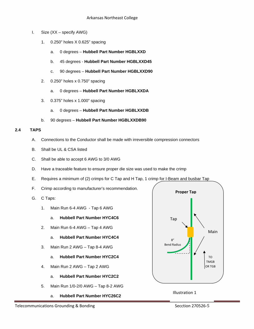
Illustration 1
8”
Bend Radius
TO
TMGB
OR TGB
Main
Tap
Proper Tap
I. Size (XX – specify AWG)
1. 0.250” holes X 0.625” spacing
a. 0 degrees – Hubbell Part Number HGBLXXD
b. 45 degrees - Hubbell Part Number HGBLXXD45
c. 90 degrees – Hubbell Part Number HGBLXXD90
2. 0.250” holes x 0.750” spacing
a. 0 degrees – Hubbell Part Number HGBLXXDA
3. 0.375” holes x 1.000” spacing
a. 0 degrees – Hubbell Part Number HGBLXXDB
b. 90 degrees – Hubbell Part Number HGBLXXDB90
2.4 TAPS
A. Connections to the Conductor shall be made with irreversible compression connectors
B. Shall be UL & CSA listed
C. Shall be able to accept 6 AWG to 3/0 AWG
D. Have a traceable feature to ensure proper die size was used to make the crimp
E. Requires a minimum of (2) crimps for C Tap and H Tap, 1 crimp for I-Beam and busbar Tap
F. Crimp according to manufacturer’s recommendation.
G. C Taps:
1. Main Run 6-4 AWG - Tap 6 AWG
a. Hubbell Part Number HYC4C6
2. Main Run 6-4 AWG – Tap 4 AWG
a. Hubbell Part Number HYC4C4
3. Main Run 2 AWG – Tap 8-4 AWG
a. Hubbell Part Number HYC2C4
4. Main Run 2 AWG – Tap 2 AWG
a. Hubbell Part Number HYC2C2
5. Main Run 1/0-2/0 AWG – Tap 8-2 AWG
a. Hubbell Part Number HYC26C2
Arkansas Northeast College
Telecommunications Grounding & Bonding Secction 270526‐6
6. Main Run 1/0-2/0 AWG – Tap 1/0-2/0 AWG
a. Hubbell Part Number HYC26C26
H. H Tap
1. Main Run 4/0-2 AWG - Tap 2-8 AWG
a. Hubbell Part Number HYH292C
2. Main Run 2-8 AWG – Tap 2-8 AWG
a. Hubbell Part Number HYH2C2C
3. Main Run 6-10 AWG – Tap 6 AWG
a. Hubbell Part Number HYH6C6C
H. I-Beam Tap
1. I-Beam steel with a Standard Flange
a. Hubbell Part Number HYGIBS####
2. I-Beam steel with a Wide Flange
a. Hubbell Part Number HYGIBW####
H. Busbar Tap
1. Bubsar thickness 0.25”, Main Run 2 AWG - Tap 6 AWG
a. Hubbell Part Number HYG14B2TC2C6C
2. Bubsar thickness 0.25”, Main Run 2 AWG – Tap 2 AWG
a. Hubbell Part Number HYG14B2TC2C2C
3. Bubsar thickness 0.25”, Main Run 4/0 – 1/0 AWG
a. Hubbell Part Number HYGBTC28
2.5 LADDER RACK BONDING CONDUCTORS
A. Ground cord assembly
1. Stranded THHN
2. Color: green
3. #6 AWG insulated bonding jumper
4. Length: 9” - 12”.
Arkansas Northeast College
Telecommunications Grounding & Bonding Secction 270526‐7
5. Each end terminated with a two hole compression lug or listing approved terminal
6. Hubbell Part Number HGRKTD12D, HGRKTKA9KA5, HGRKTKLU9KLU5
B. Braided Jumper
1. 0.94” Braid width
2. Hole diameter 0.375”
3. Hole Spacing 1.25”
4. Length: 12”
5. Hubbell Part Number HGBBD12
2.6 BASKET TRAY CONDUCTORS
A. Mounts to the basket tray metal runner
B. Accepts #6 AWG cable that spans the gaps between sections of basket tray
C. Hubbell Part Number HGBKS17, HGRKTWC45, HGRKTWB5
2.7 WRIST STRAP ESD PORT
A. Lug w/ 4mm banana plug to attach ESD wrist strap.
B. Two (2) hole lug
C. Placed inside cabinet or on equipment rack
D. Must be identifiable as an ESD connection point
E. Hubbell Part Number HGBESDKT10
2.8 RAISED FLOOR GROUNDING CLAMP
A. Ability to do both parallel and grid configurations
1. HGBGXP1828RF - Grid or Parallel
2. HGBGP1526G1 - Parallel
3. HGBGRF4C3 - Parallel
B. Attached to the stringer of the raised floor
1. HGBGXP1828RF - 0.75”-1.5” Round or Square
2. HGBGP1526G1 - 1.0”-1.25” Round
3. HGBGRF4C3 - 0.75”-1.0” Round or Square
C. Wire Range.
Arkansas Northeast College
Telecommunications Grounding & Bonding Secction 270526‐8
1. HGBGXP1828RF 6 – 4/0 AWG
2. HGBGP1526G1 4 – 2/0 AWG
3. HGBGRF4C3 8 – 2 AWG
PART 3: EXECUTION
3.1 Telecommunications Main Ground Busbar (TMGB)
A. The TMGB shall be:
1. Pre-drilled copper with holes to accommodate lug mounting holes
2. 0.25” t x 4” w with varying length
3. Sized for current applications and future growth
4. Insulated from its support
5. Maintain a 2” min clearance from wall
6. Installed to maintain clearances required by applicable codes
7. In an accessible location
8. As close to the panelboard as practicable min 36”
a. Where a panelboard (electrical power panel) is located in the same room or space as the TMGB that panelboard’s alternating current equipment ground (ACEG) bus (when equipped) or the panelboard enclosure shall be bonded to the TMGB.
9. Be Listed by a nationally recognized testing laboratory
10. 36” from active electronics or the panelboard
B. The TMGB should :
1. Be located in the telecommunication entrance facility
a. The ideal location of the TMGB is in the telecommunications entrance facility.
2. Have a mounting height adjusted to accommodate overhead or underfloor cable routing.
3. Minimize the length of bonding conductor for telecommunications
4. Provide for the shortest and straightest routing of the primary
5. Be located near backbone cabling and associated terminations
6. Serve telecommunications equipment that is located within the same room or space.
C. The TMGB may use an electro-tin plated busbar
D. Attachments to TMGB
Arkansas Northeast College
Telecommunications Grounding & Bonding Secction 270526‐9
1. Bonding Conductor – Electrical Distribution Panel
2. Primary protector
3. Building Steel
4. Outside plant cables
5. Backbone cables that incorporates a shield or metallic member
6. All metallic pathways for telecommunications cabling located within the same room or space as the TMGB.
7. Cable tray
8. Ladder rack
9. Conduit
10. Telecommunications equipment located in the TEF (e.g., multiplexer or optical fiber termination equipment).
11. TBB
12. TEBC
13. Primary protector grounding conductor
a. A minimum of 1 ft separation shall be maintained between this insulated conductor and any dc power cables, switchboard cable, or high frequency cables, even when placed in rigid metal conduit or EMT.
3.2 Telecommunication Ground Busbar (TGB)
A. The TGB shall:
1. Be a predrilled copper busbar provided with holes for use with standard sized lugs,
2. Have minimum dimensions of 6 mm (0.25 in) thick x 50 mm (2 in) wide and variable length to meet the application requirements and with consideration of future growth.
3. Be insulated from its support attachment a minimum of 2”.
4. Be listed by a nationally recognized testing laboratory (NRTL).
5. Maintain 36” separation from active electronics
B. It is acceptable that the busbar be electro-tin plated for reduced contact resistance. If not plated, the busbar shall be cleaned prior to fastening the conductors to the busbar, and an anti-oxidant should be applied to the contact area to control corrosion and reduce contact resistance.
Arkansas Northeast College
Telecommunications Grounding & Bonding Secction 270526‐10
C. The TGB is the grounding connection point for telecommunications systems and equipment in the area served by that telecommunications room or equipment room.
D. Where a panelboard is located in the same room or space as the TGB that panelboard’s ACEG bus (ac electrical ground when equipped) or the panelboard enclosure shall be bonded to the TGB. When a panelboard for telecommunications equipment is not in the same room or space as the TGB, that TGB should be bonded to the panelboard that feeds the distributor.
E. The TBBs and other TGBs within the same space shall be bonded to the TGB with a conductor the same size as the TBB.
F. Where a grounding equalizer (GE) is required, it shall be bonded to the TGB.
3.3 Telecommunications Bonding Backbone (TBB)
A. The intended function of a TBB is to reduce or equalize potential differences between telecommunications systems. While the TBB will carry some current under ac power ground fault conditions, it is no t intended to provide the only ground fault return path.
B. The TBB shall:
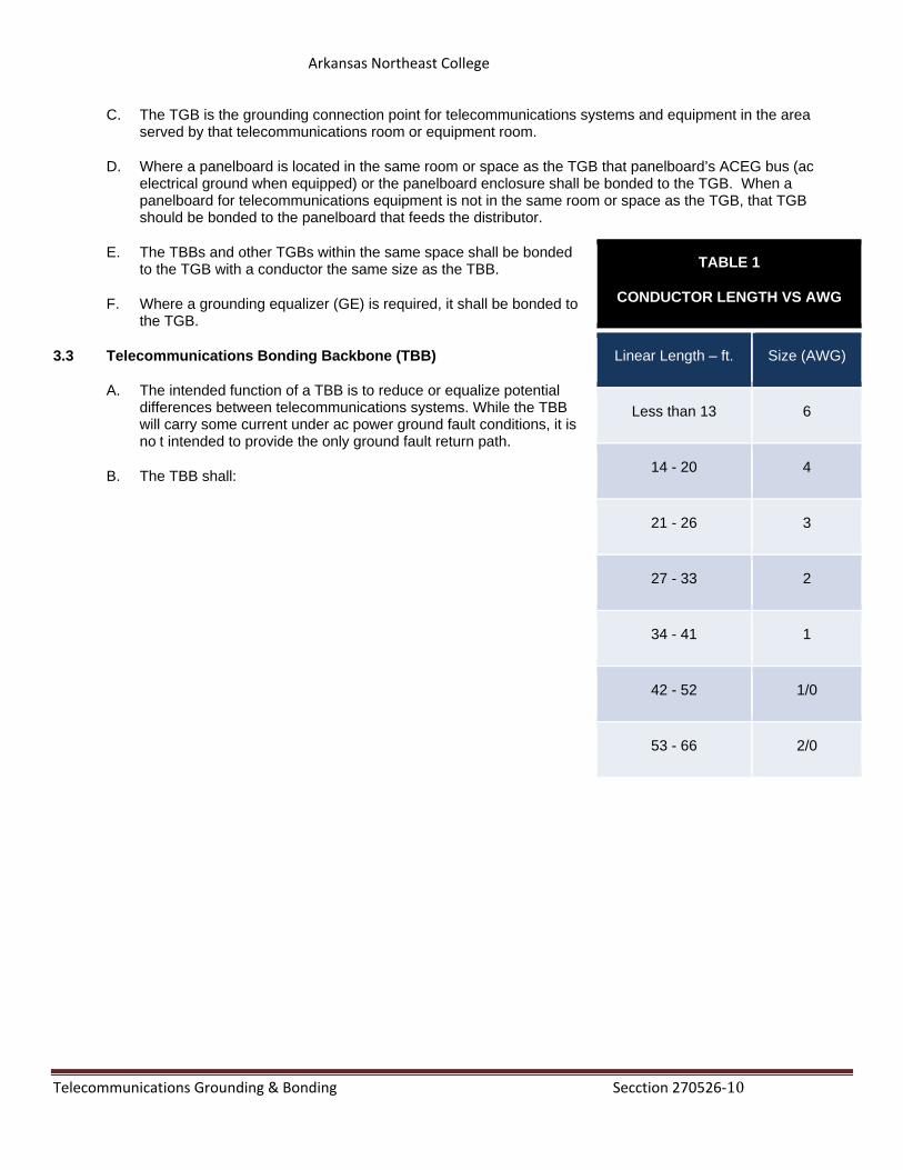
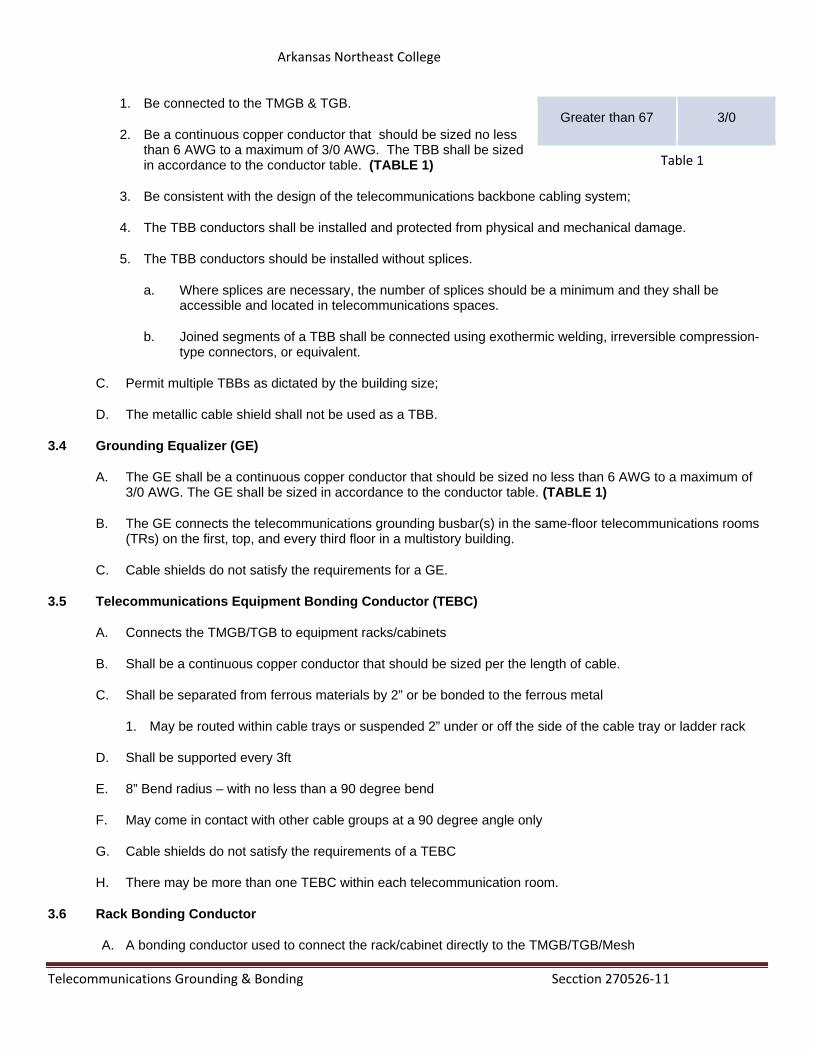
TABLE 1
CONDUCTOR LENGTH VS AWG
Linear Length – ft. Size (AWG)
Less than 13 6
14 - 20 4
21 - 26 3
27 - 33 2
34 - 41 1
42 - 52 1/0
53 - 66 2/0
Arkansas Northeast College
Telecommunications Grounding & Bonding Secction 270526‐11
1. Be connected to the TMGB & TGB.
2. Be a continuous copper conductor that should be sized no less than 6 AWG to a maximum of 3/0 AWG. The TBB shall be sized in accordance to the conductor table. (TABLE 1)
3. Be consistent with the design of the telecommunications backbone cabling system;
4. The TBB conductors shall be installed and protected from physical and mechanical damage.
5. The TBB conductors should be installed without splices.
a. Where splices are necessary, the number of splices should be a minimum and they shall be accessible and located in telecommunications spaces.
b. Joined segments of a TBB shall be connected using exothermic welding, irreversible compression-type connectors, or equivalent.
C. Permit multiple TBBs as dictated by the building size;
D. The metallic cable shield shall not be used as a TBB.
3.4 Grounding Equalizer (GE)
A. The GE shall be a continuous copper conductor that should be sized no less than 6 AWG to a maximum of 3/0 AWG. The GE shall be sized in accordance to the conductor table. (TABLE 1)
B. The GE connects the telecommunications grounding busbar(s) in the same-floor telecommunications rooms (TRs) on the first, top, and every third floor in a multistory building.
C. Cable shields do not satisfy the requirements for a GE.
3.5 Telecommunications Equipment Bonding Conductor (TEBC)
A. Connects the TMGB/TGB to equipment racks/cabinets
B. Shall be a continuous copper conductor that should be sized per the length of cable.
C. Shall be separated from ferrous materials by 2” or be bonded to the ferrous metal
1. May be routed within cable trays or suspended 2” under or off the side of the cable tray or ladder rack
D. Shall be supported every 3ft
E. 8” Bend radius – with no less than a 90 degree bend
F. May come in contact with other cable groups at a 90 degree angle only
G. Cable shields do not satisfy the requirements of a TEBC
H. There may be more than one TEBC within each telecommunication room.
3.6 Rack Bonding Conductor
A. A bonding conductor used to connect the rack/cabinet directly to the TMGB/TGB/Mesh
Greater than 67 3/0
Table 1
Arkansas Northeast College
Telecommunications Grounding & Bonding Secction 270526‐12
B. Metallic enclosures, including telecommunications cabinets and racks, shall be bonded to the mesh-BN, TGB, or TMGB using a minimum sized conductor of No. 6 AWG.
C. Cabinets, racks, and other enclosures in computer rooms shall not be bonded serially; each shall have their own dedicated bonding conductor to the mesh-BN, TGB, or TMGB.
3.7 Electrical distribution panel (EDP)
A. When located in the same room as the TMGB/TGB the EDP's equipment grounding bus or the panel board enclosure shall be bonded to the TMGB/TGB
B. Using a bonding conductor for telecommunications (BCT) minimum 6 AWG to a maximum of 3/0 AWG depending on the length of cable required.
C. Use same AWG as TBB
D. A qualified electrician shall make all connections within an ac electrical panel.
E. Outside of the scope of ANSI/TIA-607B
3.8 Conductive Fiber Optic Cables
A. The metallic components of a conductive cable are capable of transmitting current.
B. Conductive fiber-optic cables should be bonded and grounded as specified in NEC Article 770.100
3.9 Ladder Rack and/or Cable Tray
A. To achieve the objective of potential equalization in the TR, all cable runway sections are bonded together and bonded back to the TMGB/TGB
B. Maintain a 8” Bend Radius on the TEBC
C. Keep a 2” separation from other cables, power and telecommunications
D. Remove any paint, oxidation, ect. from the runway surfaces that are being bonded
E. Drill two holes as required to accommodate the 2-hole compression lug
F. Apply a thin coat of antioxidant around the holes and on the surface where the lug will be in contact.
G. Attach straps to the runway using stainless steel hardware sized for the lug holes.
H. Tighten the hardware
I. Wipe off any excess antioxidant after installation of the lug.
3.10 Labeling
A. The format for the telecommunications main grounding busbar shall be FS-TMGB, while the format for the TGBs shall be FS-TGB.
1. FS is the TS identifier for the space containing the busbar; Floor & space
Arkansas Northeast College
Telecommunications Grounding & Bonding Secction 270526‐13
Illustration 2
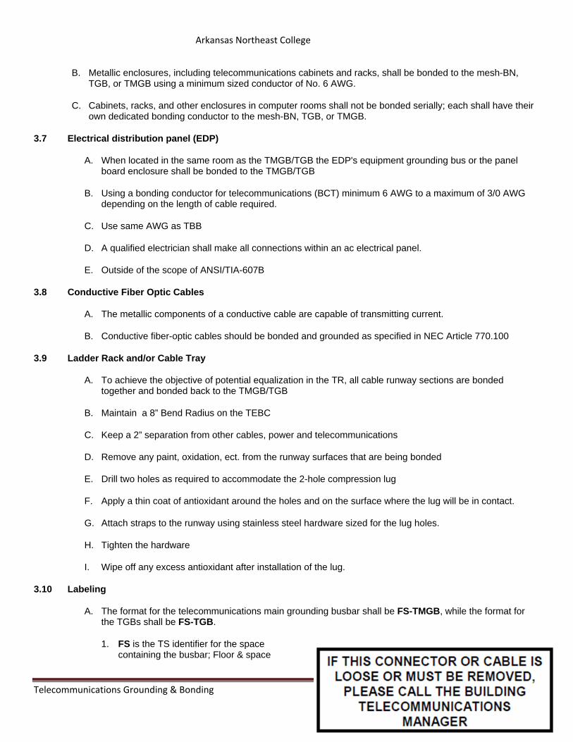
2. TMGB is the portion of an identifier designating a telecommunications main grounding busbar;
3. TGB is the portion of the identifier designating a telecommunications grounding busbar.
B. Each telecommunications space or room shall be assigned an identifier unique within the building. The TS shall be labeled with the TS identifier inside the room so as to be visible to someone working in that room. The TS identifier shall have a format of FS.
C. All busbars and cables will have the label in Illustration 2 attached, and it will be visible .and readable
3.11 Testing
A. Earth ground resistance tester
1. The earth ground resistance tester generates a specific test current: this current is less susceptible to the influences of stray currents on the grounding system. This makes the ground resistance tester a more accurate testing devise that a standard Volt-Ohm-multimeter.
B. Two-point ground continuity testing
1. Maximum value 100 milliohms
C. Follow manufacture instructions on setup and how to perform the test.
D. Care should be taken and safety precautions in place
Arkansas Northeast College
Telecommunications Grounding & Bonding Secction 270526‐14
Arkansas Northeast College
TELECOMMUNICATIONS OUTSIDE PLANT (OSP) 27 05 43 - 1
SECTION 27 05 43 - Underground ducts and raceways for Communication Systems-OSP
PART 1 - GENERAL
1.1 DESCRIPTION
A. Furnish and install telecommunications outside plant (OSP) facilities as indicated on drawings and set forth hereinafter.
1.2 REFERENCE STANDARDS
A. See section 27.01.00 REFERENCE STANDARDS.
B. ANSI/TIA/EIA 758, Customer Owned Outside Plant Telecommunications Cabling Standard.
C. ANSI/TIA/EIA-526, 7 and 14, Telecommunications Measurements of Optical Fiber Single and Multi Mode Power Loss.
PART 2 - PRODUCTS
2.1 MATERIALS
A. Inner Duct: MaxCell 3x3 (MXD3456), locatable for OSP, with color ID.
B. Fiber Optic OSP Cable: Single Mode 24 strand– Corning Altos OS2 XXXEU4-T4101D20(black)(XXX=strand count).
C. Phone Cable: 25 pair PE89 BSW (Buried Service Wire) Phone Cable-as manufactured by Essex or General Cable.
D. Handholes - Handhole lids with "Communications" logo on cover of lid.
PART 3 - EXECUTION
3.1 INSTALLATION
A. Provide three (3) 3x3 "MaxCell" innerducts in two of the 4" conduits entering building from OSP system. Provide conduits over 1” not filled with MaxCell, install 3/8” nylon rope with a pull rating of 200lb or more. Conduits 1” or less, fill with polyline (Greenlee 430). Each MaxCell is to have different color ID marking and shall be locatable. The use of flexible plastic innerduct shall not be permitted.
B. The use of 90-degree bends shall be prohibited for OSP conduits. Long communications sweeps shall be utilized where conduit turns are required. Use Schedule 80 PVC, under sidewalks, driveways, etc. Use Schedule 40 PVC elsewhere. Conduit to be free of water and debris throughout. Provide caps on ends.
Arkansas Northeast College
TELECOMMUNICATIONS OUTSIDE PLANT (OSP) 27 05 43 - 2
C. OSP conduits shall be marked with Detectable Warning Tape, CH Hansen 16626 or equal.
D. Handholes (HH) shall be 36"x48”x 36" minimum size, with open bottom (on top of 4" rack). Seal conduits at each HH to keep moisture, insects, and rodents out of building. Conduits entering building must be sloped. All Handholes where fiber splices are made shall be 36”x60”x36” minimum. Use Quazite PG style with pull slot center pins, lid shall be labeled “COMMUNICATIONS”.
E. All OSP cabling shall be installed in neat and workmanlike manner. Cabling to be routed and secured around edges of HH to create additional space for future cabling.
F. Provide 25 foot maintenance loop for fiber optic lines in one HH. Service loop to side of HH.
G. Label all OSP cabling as follows:
1. "Caution Fiber Optic" adhesive marker every HH. Label to include SM an MM fiber count and "to and from". 2. "Caution Fiber Optic" adhesive marker every 50' of exposed fiber in building (including in cable tray). Label
to include SM and MM fiber count and "to and from". 3. OSP UTP cables shall be labeled with permanent, neat penmanship in every HH with "to and from".
H. Prior to backfill, contractor shall arrange for inspection of OSP installation with Sample Specification ITS Department.
I. Prior to commencing with work, a pre-construction meeting will be held between the contractor's telecommunications cabling installer and appropriate representatives of the Sample Specification Physical Plant, ITS Department. Installation requirements shall be carefully discussed at the pre-construction meeting. Discrepancies between contract documents and pre-construction meeting shall be called to the attention of Project Engineer immediately prior to commencing with any telecommunications installation work.
J. All conduit shall be installed such that the top of the conduit is a minimum of 24” below grade.
END OF SECTION 27 05 28
Arkansas Northeast College
HANGERS AND SUPPORT 27 05 29 - 1
SECTION 27 05 29 - HANGERS AND SUPPORT
PART 1 - GENERAL
1.1 SCOPE OF WORK
A. Furnish and install a system of cabling supports above ceilings for network, voice, and CATV cabling as set forth hereinafter.
1.2 REFERENCE STANDARDS
A. See SECTION 27.01.00 REFERENCE STANDARDS
B. See SECTTION27.11.13 Communications Grounding and Bonding
PART 2 - PRODUCTS
2.1 Basket Tray 1. All wire trays are to be UL classified. 2. All wire tray shall be approved for grounding. 3. All wire tray shall be approved for installations in overhead or under-floor applications. 4. All wire tray shall have shaped cross members to reduce cable strain. 5. All wire tray shall be 100% recycled steel content. 6. Manufacture: Hubbell Pre-Galvanized HBT series (size dependant)
2.2 Ladder Tray 1. Material: 16 ga. tubular steel. 2. Durable powder coat. 3. Stringer dimensions: 0.375”W x 1.5”H. 4. Rung spacing: 9.0”. 5. Weight capacity: 45 lbs./foot. 6. Manufacture: Hubbell HLS series
Use 18 inch wide in all entrance and telecommunications rooms. Use other sizes as needed in corridors (size dependant).
2.3 J-Hooks 1. J-Hooks are not to be used except when no basket tray or ladder tray can be used. 2. Non-Metallic J-Hooks for CAT6 is limited to maximum of 10 cables. All cables (CAT5E, CAT6, Coax) must be secured every 4’-5’, anchor J-hooks to studs. 3. Steel J-hooks shall not be used. 4. J-hooks shall be as follows:Use Non-Metallic J-hooks, as made by Erico.
Arkansas Northeast College
HANGERS AND SUPPORT 27 05 29 - 2
PART 3 - EXECUTION
3.1 INSTALLATION
A. Entire installation shall be in accordance with manufacturer's recommendations.
B. Provide two separate sets of low-voltage cabling supports along entire length of low-voltage cabling runs above ceiling. One set of supports shall be of Category 6 network wiring. The second set of supports shall be for CATV wiring. Locate supports well clear of acoustical lay-in ceiling tiles. Supports shall be located such that tiles can be removed without interfering with support system.
C. Coordinate installation of low-voltage supports with other trades as required.
D. All trays shall be bonded and grounded to the telecommunications grounding system per SECTTION27.11.13 Communications Grounding and Bonding.
END OF SECTION 27 05 29
Arkansas Northeast College
ADMINISTRATION LABELING 27 05 53 - 1
SECTION 27 05 53 - ADMINISTRATION / LABELING
PART 1 – GENERAL
1.1 DESCRIPTION
A. Provide administration and labeling of entire communications infrastructure in accordance with Sample Specification ITS Department requirements and as set forth hereinafter. Administration and labeling shall include but not be limited to all work area outlets (WAO's), patch panels, 110 blocks, conduits, cable trays, backbone cables, etc.
1.2 REFERENCE STANDARDS
A. See SECTION 27.01.00 REFERENCE STANDARDS
PART 2 - PRODUCTS
2.1 MATERIALS
A. Products shall be as set forth elsewhere in these specifications.
PART 3 – EXECUTION
3.1 INSTALLATION
A. All WAO's, patch panels, 110 blocks, conduits, cable trays, backbone cabling, outside plant cabling, etc., shall be labeled according to ANSI/TIA Standards with specific labeling scheme of Sample Specification from Arkansas Northeast College ITS Department. Labeling is also to include the following:
1. "Caution Fiber Optic" adhesive marker every 20' of exposed fiber in building (including in cable tray). Label to include SM and MM fiber count and "to and from".
END OF SECTION 27 05 53
Arkansas Northeast College
REFERENCE STANDARDS 27 08 00 - 1
SECTION 27 08 00 - Commissioning of Communications
PART 1 - GENERAL
1.1 DESCRIPTION
A. Telecommunications systems shall be provided as indicated on drawings and as called for hereinafter.
1.2 REFERENCE STANDARDS
A. B. BICSI TDMM current edition (Telecommunications Distribution Methods Manual).
B. ANSI/NECA/BICSCI-568, Standard for Installing Commercial Building Telecommunications Cable.
C. ANSI/TIA 569-C, Pathways and Spaces.
D. ANSI/TIA 568-C.0, Generic Telecommunications for Customer Premises Standard Series
i. 568-C.1 Commercial Building Cabling
ii. 568-C.2 Copper Cabling Components
iii. 568-C.3 Fiber Cabling Components
iv. 568-C.4 Coax Cabling Components
E. ANSI/TIA 606-B, Addendum 1, Administration Standard for Commercial Telecommunications Infrastructure.
F. ANSI J-STD-607-B, Commercial Building Grounding (Earthing) and Bonding Requirements for Telecommunications.
G. ANSI/TIA 758-B, Customer owned Outside Plant Telecommunications Cabling Standard
H. ANSI/TIA-526, 7&14, Telecommunications Measurements of Optical Fiber Single and Multi Mode Power Loss
I. ANSI/TIA Building Automation Systems Cabling Standard for Commercial Buildings
J. ANSI/TIA 310-D, Cabinets, Racks, Panels, and Associated Equipment.
K. FCC Part 68, Connection of Terminal Equipment to the Telephone Network.
L. ADA of 2010 and Telecommunications Act of 1996, Physically Impaired and Accessibility.
M. IEEE 802-2002, Standard for Local and Metropolitan Networks: Overview and Architecture.
N. IEEE 802.11ax Wireless LAN’s
O. NFPA 70, National Electrical Code (2014).
P. NFPA-76, Recommended Practice for Fire Protection of Telecommunications Facilities.
Q. NFPA 101, Life Safety Code.
Arkansas Northeast College
REFERENCE STANDARDS 27 08 00 - 2
R. ETA Electronic Technician Association Fiber Optics Installer
S. FOA Fiber Optics Association Certified Fiber Optics Technician
T. ANSI/SCTE 77 Underground Enclosure Integrity
1.3 Reference Specifications
A. See section 27.01.00 for standards.
B. See section 27.05.53 Administration/Labeling.
C. See section 27.05.26 Grounding and bonding.
D. See section 27.15.00 Voice and Network Horizontal Cabling System PART 2 - PRODUCTS 2.1 Inspections and Walk Through
All work is subject to inspection and review at anytime by qualified Arkansas Northeast College personnel. All rough in work will be inspected by Arkansas Northeast College personnel before finished walls and ceilings are
installed. Final walk through inspections must be done prior to turning in final documentation and test results. The
preliminary documentations will be made available for review during this walk through inspection. Cables with visible defects, kinks, twists, crushed, cuts or smashed will be replaced regardless if they pass tests. Installer must take reasonable steps to protect their installation in a construction environment. Free of dirt, defects
and debris
PART 3 - EXECUTION 3.1 Commissioning
Arkansas Northeast College ITS requires the newly installed infrastructure to be tested and certified. Follow the Standards of ANSI/TIA -568-C.1,2,3,4 for testing criteria of the permanent link. See Appendix D in the Arkansas Northeast College Telecommunications Design and Installations Guidelines, current edition for approved test equipment to obtain a manufacture warranty.
Testing shall commence only after all materials are permanently installed, adjusted, bonded and labeled. Installer must retest and save both the original and retested results when any of the above occurs.
Testing shall commence only in a clean environment, free of moisture, dirt, dust and debris. Terminations exposed to such environments after testing will require retesting.
In addition to the cabling being commissioned and certified, the electrical grounding and bonding systems must also be tested and certified.
The electrical contractor is responsible for testing the Alternating Current (AC) Grounding Electrode System. The telecommunications installer is responsible for testing the Equipment Grounding (Bonding) System. Refer to the BICSI TDMM latest edition, for approved test equipment and acceptable results.
\
Arkansas Northeast College
REFERENCE STANDARDS 27 08 00 - 3
END OF SECTION 27 01 00
Arkansas Northeast College
REFERENCE STANDARDS 27 11 13- 1
SECTION 27 11 13- Communication Entrance Protection
PART 1 - GENERAL
1.1 DESCRIPTION
A. Telecommunications systems shall be provided as indicated on drawings and as called for hereinafter.
1.2 REFERENCE STANDARDS
A. BICSI TDMM current edition (Telecommunications Distribution Methods Manual).
B. ANSI/NECA/BICSCI-568, Standard for Installing Commercial Building Telecommunications Cable.
C. ANSI/TIA 569-C, Pathways and Spaces.
D. ANSI/TIA 568-C.0, Generic Telecommunications for Customer Premises Standard Series
i. 568-C.1 Commercial Building Cabling
ii. 568-C.2 Copper Cabling Components
iii. 568-C.3 Fiber Cabling Components
iv. 568-C.4 Coax Cabling Components
E. ANSI/TIA 606-B, Addendum 1, Administration Standard for Commercial Telecommunications Infrastructure.
F. ANSI J-STD-607-B, Commercial Building Grounding (Earthing) and Bonding Requirements for Telecommunications.
G. ANSI/TIA 758-B, Customer owned Outside Plant Telecommunications Cabling Standard
H. L. FCC Part 68, Connection of Terminal Equipment to the Telephone Network.
I. P. NFPA 70, National Electrical Code (2014).
J. Q. NFPA-76, Recommended Practice for Fire Protection of Telecommunications Facilities.
K. R. NFPA 101, Life Safety Code.
L. U. ANSI/SCTE 77 Underground Enclosure Integrity
PART 2 - PRODUCTS 2.1 Entrance Facility (EF) UTP protectors
1. An EF is a space where telecommunications outside plant (OSP) terminates to the inside facilities. The outside plant will most likely be fiber optics LAN, CATV coax, UTP telephone and MaxCell innerduct. (27 11 13)
2. UTP protectors shall have the following: Building Entrance Terminals enclosure
Arkansas Northeast College
REFERENCE STANDARDS 27 11 13- 2
INDOOR - 110 CONNECTOR 16 AWG Powder Coated Steel Construction Equipped with an Internal 26 AWG Fuse Link External Ground Connectors Accept 6 - 14 AWG Wire Industry Standard 5 Pin Design Exceeds UL497 Primary Protection Standards
PART 3 - EXECUTION 1. OSP cables routed inside a building are influenced by fire codes. The installer should be aware of and adhere to
local codes, standards and regulations.
2. OSP cable is to be terminated or transitioned to listed cable as close as practical upon entry to the building. In no case must this termination or transition exceed 50 feet from point of entrance for exposed cable. The installer may extend the point of entry by enclosing the unlisted outside cables in a rigid or intermediate metal conduit that extends beyond the wall or floor of the building and is properly sealed and bonded to a grounding electrode. At no point shall this cable be exposed prior to the termination point.
3. All telephone and data cables (Cat 3) and (Cat 5) shall be protected at the entrance facility.
4. Manufacture: UTP Protectors (CAT3) Circa 1880 series, 110 block, 5 pin modules 4B1S-300. CAT5e, Linx CAT5e-75
END OF SECTION 27 11 13
Arkansas Northeast College
VOICE AND NETWORK HORIZONTAL CABLING SYSTEM 27 15 00 - 1
SECTION 27 15 00 - VOICE AND NETWORK HORIZONTAL CABLING SYSTEM
PART 1 - GENERAL
1.1 DESCRIPTION
A. Furnish and install voice and network cabling for the building as indicated on drawings and as called for hereinafter. This specification is for a voice and network cabling system. Products specified hereinafter are Hubbell cable and Hubbell connectivity including jacks, patch panels, patch cords, and faceplates shall be utilized. The Hubbell products specified hereinafter are utilized as campus standard for Arkansas Northeast College . Any proposed replacement products must meet or exceed the published specifications. Alternates must be verified with Arkansas Northeast College ITS by furnishing proper documentation of specifications verified by an industry-recognized test laboratory (U.L., ETL, ASTM).
B. This standard also establishes performance criteria for various system configurations and their elements.
C. Installer of cabling installation specified herein must be a certified trained installer using ANSI TIA Standards and the current edition of the BICSI TDMM (Telecommunications Distribution Methods Manual, Current Edition) as a guide for installation of inside cabling and associated components. Installer must be Hubbell Certified. Provide written documentation of these qualifications as part of the submittal process.
1.2 CABLING STRUCTURE
A. The elements of a cabling system are listed below:
1. Horizontal Cabling 2. Work Area Outlets (WAO) 3. ER Rooms (See Section 27.11. 00) 4. TR Rooms (See Section 27.11. 00)
B. HORIZONTAL CABLING
1. Horizontal cabling shall be of star topology, each work area connector shall be terminated in the telecommunications room. The maximum horizontal distance from ER to the WAO shall be 90 meters. When deductions are made for mandatory minimum slack, the cable distance is approximately 85 meters (281 feet).
2. The amount of untwisting of individual pairs to terminate shall be less than or equal to .5 in. for Category 6. 3. Minimum bend radius shall be 4 times the cable diameter.
C. REFERENCE STANDARDS
1. See section 27.01.00 for standards.
2. See section 27.05.53 Administration/Labeling.
3. See section 27.05.26 Grounding and bonding.
4. See section 270800 Commissioning of Communications
Arkansas Northeast College
VOICE AND NETWORK HORIZONTAL CABLING SYSTEM 27 15 00 - 2
D. ADMINISTRATION STANDARD FOR COMMUNICATIONS INFRASTRUCTURE:
1. Purpose: The purpose of this standard is to provide a uniform administration scheme that is independent of the applications. This standard defines guidelines for contractors involved in the installation of the computer cabling system.
2. Scope: This standard specifies the administrative requirements of the communications infrastructure within a building or campus.
3. Areas to be administered are as follows:
a) Terminations for the communications media b) Communications media between terminations c) Pathways between terminations
a. d) Spaces where terminations are located e) Bonding and grounding
4. Pathway and Space Administration: All spaces must be labeled. Labels should be affixed at the entrance of the space.
5. Wiring System Administration: This section describes the administration of cables, termination hardware, splices and termination position. As changes are made, effected labels, records, drawings and reports shall be updated.
a. Horizontal and backbone subsystem cables shall be labeled at each end. b. Each termination hardware or label shall be marked with an identifier. c. Each termination position label shall be recorded with an identifier. d. Each splice closure or label shall be marked with an identifier. e. "TMGB" shall be marked on the Telecommunications Main Grounding Busbar.
E. LABELING AND COLOR CODING:
1. Labels are divided into 3 categories:
a) Adhesive labels shall meet adhesion, defacement and legibility requirements defined in U.L. 969. Labels shall also meet exposure requirements in U.L. 969.
b) Insert labels shall also meet U.L. 969 requirements for defacement, legibility and general exposure. c) Other labels include special purpose labels, such as tie-on labels. d) Labels shall be used instead of marking the cable.
2. All bar codes shall be either Code 39 or Code 128 confirming to USS-39 and USS-128 respectively. All Code 39 bar code ratios shall be within 2.5:1 to 3.0:1. If a wand scanner is to be used, a minimum quiet zone of 6.35mm is required on each side of the bar code.
3. Refer to ITS Guidelines, Appendix M
F. COLOR CODING RULES:
1. Termination labels at the two ends of the cable shall be of the same color. 2. Cross-connectors made between termination fields are generally of two different colors. 3. The color orange is used for the demarcation point. 4. Blue is for the network connections on the customer side of the demarcation point.. 5. Yellow is for termination of wi-fi wireless access circuits.
Arkansas Northeast College
VOICE AND NETWORK HORIZONTAL CABLING SYSTEM 27 15 00 - 3
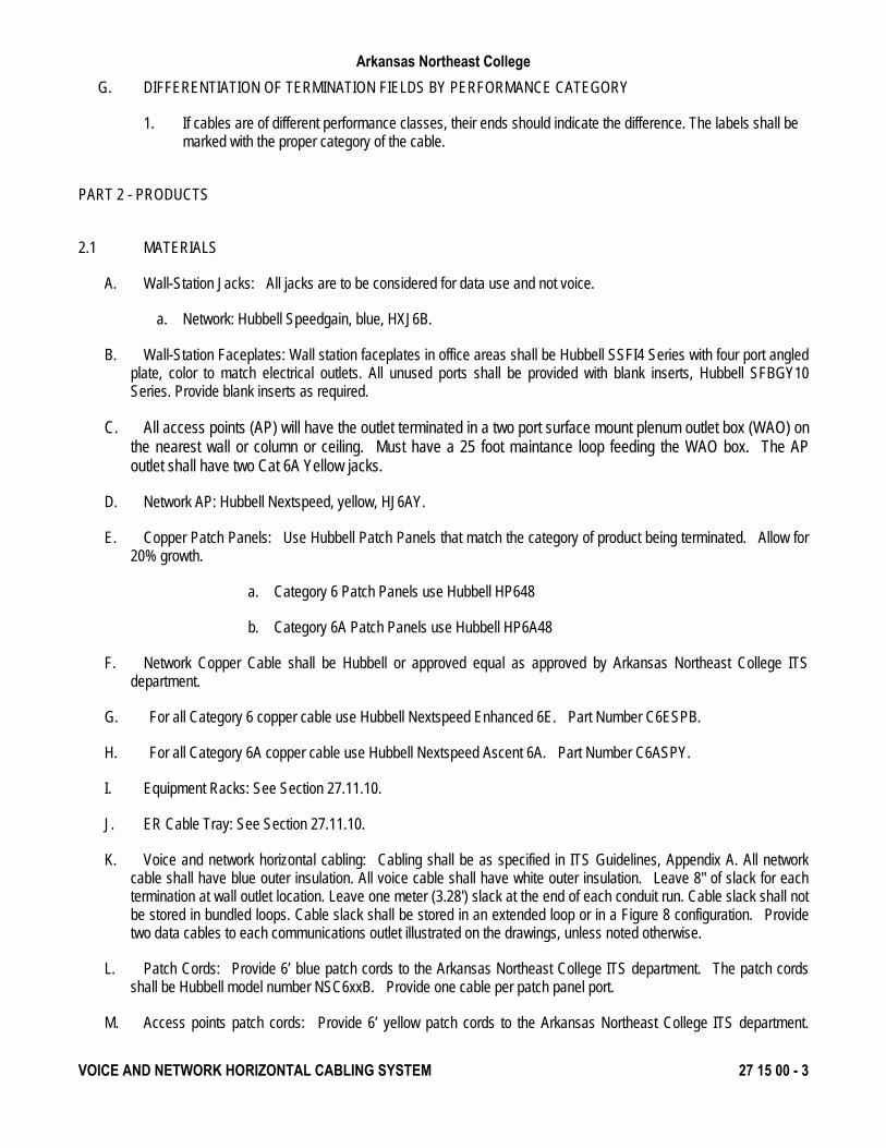
G. DIFFERENTIATION OF TERMINATION FIELDS BY PERFORMANCE CATEGORY
1. If cables are of different performance classes, their ends should indicate the difference. The labels shall be marked with the proper category of the cable.
PART 2 - PRODUCTS
2.1 MATERIALS
A. Wall-Station Jacks: All jacks are to be considered for data use and not voice.
a. Network: Hubbell Speedgain, blue, HXJ6B.
B. Wall-Station Faceplates: Wall station faceplates in office areas shall be Hubbell SSFI4 Series with four port angled plate, color to match electrical outlets. All unused ports shall be provided with blank inserts, Hubbell SFBGY10 Series. Provide blank inserts as required.
C. All access points (AP) will have the outlet terminated in a two port surface mount plenum outlet box (WAO) on the nearest wall or column or ceiling. Must have a 25 foot maintance loop feeding the WAO box. The AP outlet shall have two Cat 6A Yellow jacks.
D. Network AP: Hubbell Nextspeed, yellow, HJ6AY.
E. Copper Patch Panels: Use Hubbell Patch Panels that match the category of product being terminated. Allow for 20% growth.
a. Category 6 Patch Panels use Hubbell HP648
b. Category 6A Patch Panels use Hubbell HP6A48
F. Network Copper Cable shall be Hubbell or approved equal as approved by Arkansas Northeast College ITS department.
G. For all Category 6 copper cable use Hubbell Nextspeed Enhanced 6E. Part Number C6ESPB.
H. For all Category 6A copper cable use Hubbell Nextspeed Ascent 6A. Part Number C6ASPY.
I. Equipment Racks: See Section 27.11.10.
J. ER Cable Tray: See Section 27.11.10.
K. Voice and network horizontal cabling: Cabling shall be as specified in ITS Guidelines, Appendix A. All network cable shall have blue outer insulation. All voice cable shall have white outer insulation. Leave 8" of slack for each termination at wall outlet location. Leave one meter (3.28') slack at the end of each conduit run. Cable slack shall not be stored in bundled loops. Cable slack shall be stored in an extended loop or in a Figure 8 configuration. Provide two data cables to each communications outlet illustrated on the drawings, unless noted otherwise.
L. Patch Cords: Provide 6’ blue patch cords to the Arkansas Northeast College ITS department. The patch cords shall be Hubbell model number NSC6xxB. Provide one cable per patch panel port.
M. Access points patch cords: Provide 6’ yellow patch cords to the Arkansas Northeast College ITS department.
Arkansas Northeast College
VOICE AND NETWORK HORIZONTAL CABLING SYSTEM 27 15 00 - 4
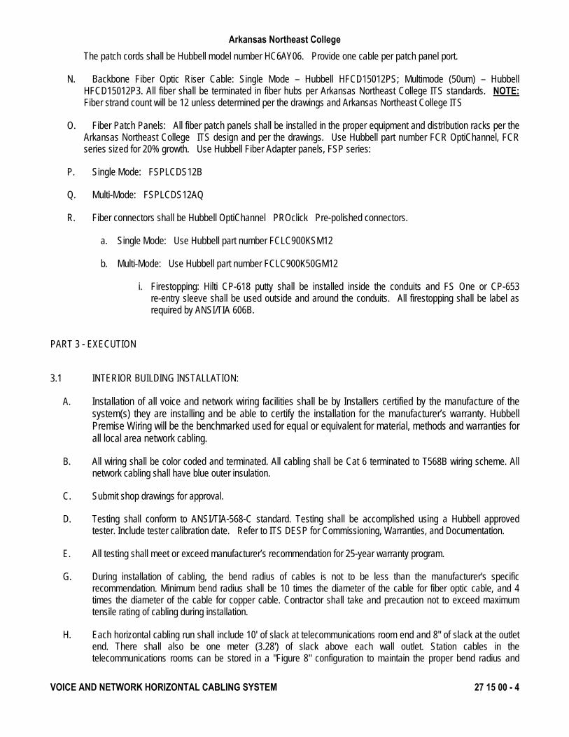
The patch cords shall be Hubbell model number HC6AY06. Provide one cable per patch panel port.
N. Backbone Fiber Optic Riser Cable: Single Mode – Hubbell HFCD15012PS; Multimode (50um) – Hubbell HFCD15012P3. All fiber shall be terminated in fiber hubs per Arkansas Northeast College ITS standards. NOTE: Fiber strand count will be 12 unless determined per the drawings and Arkansas Northeast College ITS
O. Fiber Patch Panels: All fiber patch panels shall be installed in the proper equipment and distribution racks per the Arkansas Northeast College ITS design and per the drawings. Use Hubbell part number FCR OptiChannel, FCR series sized for 20% growth. Use Hubbell Fiber Adapter panels, FSP series:
P. Single Mode: FSPLCDS12B
Q. Multi-Mode: FSPLCDS12AQ
R. Fiber connectors shall be Hubbell OptiChannel PROclick Pre-polished connectors.
a. Single Mode: Use Hubbell part number FCLC900KSM12
b. Multi-Mode: Use Hubbell part number FCLC900K50GM12
i. Firestopping: Hilti CP-618 putty shall be installed inside the conduits and FS One or CP-653 re-entry sleeve shall be used outside and around the conduits. All firestopping shall be label as required by ANSI/TIA 606B.
PART 3 - EXECUTION
3.1 INTERIOR BUILDING INSTALLATION:
A. Installation of all voice and network wiring facilities shall be by Installers certified by the manufacture of the system(s) they are installing and be able to certify the installation for the manufacturer’s warranty. Hubbell Premise Wiring will be the benchmarked used for equal or equivalent for material, methods and warranties for all local area network cabling.
B. All wiring shall be color coded and terminated. All cabling shall be Cat 6 terminated to T568B wiring scheme. All network cabling shall have blue outer insulation.
C. Submit shop drawings for approval.
D. Testing shall conform to ANSI/TIA-568-C standard. Testing shall be accomplished using a Hubbell approved tester. Include tester calibration date. Refer to ITS DESP for Commissioning, Warranties, and Documentation.
E. All testing shall meet or exceed manufacturer’s recommendation for 25-year warranty program.
G. During installation of cabling, the bend radius of cables is not to be less than the manufacturer's specific recommendation. Minimum bend radius shall be 10 times the diameter of the cable for fiber optic cable, and 4 times the diameter of the cable for copper cable. Contractor shall take and precaution not to exceed maximum tensile rating of cabling during installation.
H. Each horizontal cabling run shall include 10' of slack at telecommunications room end and 8" of slack at the outlet end. There shall also be one meter (3.28') of slack above each wall outlet. Station cables in the telecommunications rooms can be stored in a "Figure 8" configuration to maintain the proper bend radius and
Arkansas Northeast College
VOICE AND NETWORK HORIZONTAL CABLING SYSTEM 27 15 00 - 5
provide the needed slack.
I. All cables with noticeable signs of damage, kinks, crush, or stress marks shall be replaced regardless of test results.
J. Labeling of cables, wall outlets, 110 blocks, conduits, cable trays, patch panels, and backbone cabling shall be performed in accordance with requirements of the Arkansas Northeast College ITS Department.
K. Building Automation System (BAS) Connection: Cabling connecting BAS to the Arkansas Northeast College ITS network must follow the standards set forth in ANSI/TIA 862.
END OF SECTION 27 15 00
Arkansas Northeast College
COAX HORIZONTAL CABLING 27 15 33 - 1
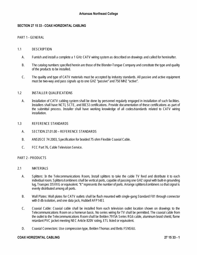
SECTION 27 15 33 - COAX HORIZONTAL CABLING
PART 1 - GENERAL
1.1 DESCRIPTION
A. Furnish and install a complete a 1 GHz CATV wiring system as described on drawings and called for hereinafter.
B. The catalog numbers specified herein are those of the Blonder-Tongue Company and constitute the type and quality of the products to be installed.
C. The quality and type of CATV materials must be accepted by industry standards. All passive and active equipment must be two-way and pass signals up to one GHZ "passive" and 750 MHZ “active”.
1.2 INSTALLER QUALIFICATIONS
A. Installation of CATV cabling system shall be done by personnel regularly engaged in installation of such facilities. Installers shall have NCTI, SCTE, and BICSI certifications. Provide documentation of these certifications as part of the submittal process. Installer shall have working knowledge of all codes/standards related to CATV wiring installation.
1.3 REFERENCE STANDARDS
A. SECTION 27.01.00 – REFERENCE STANDARDS
B. ANSI/SCE 74 2003, Specification for braided 75 ohm Flexible Coaxial Cable.
C. FCC Part 76, Cable Television Service.
PART 2 - PRODUCTS
2.1 MATERIALS
A. Splitters: In the Telecommunications Room, Install splitters to take the cable TV feed and distribute it to each individual room. Splitters/combiners shall be vertical ports, capable of passing one GHZ signal with built-in grounding lug, Truespec DSVXG or equivalent. "X" represents the number of ports. Arrange splitters/combiners so that signal is evenly distributed among all ports.
B. Wall Plates: Wall plates for CATV outlets shall be flush mounted with single-gang Standard F81 through connector with 0 db isolation, and one data jack, Hubbell AFP14EI.
C. Coaxial Cable: Coaxial cable shall be installed from each television outlet location shown on drawings to the Telecommunications Room on a homerun basis. No series wiring for TV shall be permitted. The coaxial cable from the outlet to the Telecommunications Room shall be Belden 7915A Series RG6 cable, aluminum braid shield, flame retardant PVC jacket meeting NEC Article 820V rating, ETL listed or equivalent.
D. Coaxial Connectors: Use compression type, Belden Thomas and Betts FSNS6U.
Arkansas Northeast College
COAX HORIZONTAL CABLING 27 15 33 - 2
E. RG11 Coax installation:
1. RG11 Riser Coax shall be Belden 9011 if under 300 feet and Comscope PIII750JCASS over 300ft.
2. RG11 Fitting shall be Thomas and Betts 716SNS1P11H
PART 3 - EXECUTION
3.1 INSTALLATION
A. Each coaxial cable shall be tested for signal loss, length of cable, and meet the manufacturers specifications.. Testing shall be in accordance with FCC Part 76 signal leakage requirements. Coaxial cable tests will involve continuity and RF leakage, 20-uV/m leakage limit (10 feet from network). Limit will yield a dipole level of -43.67 dBmV 75 ohms. Carefully coordinate tie-in of incoming line with local cable operator. Complete TV feed to each individual outlet to verify that a proper signal is being distributed. After proper documentation disconnect each room at the headend location and make each connection for proper identification.
B. Cable drops shall be bundled by use of approved plastic ties. Tape shall not be permitted to bundle cable drops.
C. Grounding will meet NEC requirements for CATV. Refer to Article 820 of National Electrical Code for information.
END OF SECTION 27 15 33