Embed Size (px)
Citation preview

ARM-ETM Programming Dialog
TRACE32 Online Help
TRACE32 Directory
TRACE32 Index
TRACE32 Documents ......................................................................................................................
ICD In-Circuit Debugger ................................................................................................................
Processor Architecture Manuals ..............................................................................................
ARM/CORTEX/XSCALE ...........................................................................................................
ARM-ETM Programming Dialog .......................................................................................... 1
Initialization ........................................................................................................................ 2
Initialization of the ETM 2
Programming ..................................................................................................................... 3
How to Start 3
Elements in the Dialog Box 3
Actions 5
Events 6
Levels 7
ETM ALL 0, Clear, Load, View, Save … 11
Definitions 12
Address/Range Definition 12
Data Definition 16
Counter Definition 18
Examples 20
Example 1: Selective Trace on an Address Range 20
Example 2: Selective Trace on an Address Range defined through a Symbol 22
Example 3: Selective Trace on Access to a Symbol 24
Example 4: Trace the Entrance and Exit of Function Sieve 26
Example 5: Trace the first 200H Cycles in Function Sieve 27
Example 6: Trace all, when Function Sieve is reached goto Level 1 and stop Sampling and Debugging after 5 Cycles 28
ARM-ETM Programming Dialog 1 ©1989-2018 Lauterbach GmbH

ARM-ETM Programming Dialog
Version 22-Mar-2018
Initialization
Initialization of the ETM
Initialize the ETM by using ETM Settings in the Trace menu or by entering the command ETM.state.
The broadcasting of the program flow can be controlled by TraceInclude (restrict the broadcasting of the program flow to the defined range) or TraceExclude (do not broadcast the program flow within the defined range). Either TraceInclude or TraceExclude can be specified.
The broadcasting of the data flow can be controlled by DataViewInclude (restrict the broadcasting of the data accesses to the defined range) or DataViewExclude (do not broadcast the data flow within the defined range).
For further details of this window please look for the manual RiscTrace for ARM-ETM.
ARM-ETM Programming Dialog 2 ©1989-2018 Lauterbach GmbH

Programming
How to Start
The ETM Programming Dialog can be found on any TRACE32 CD dated September 2000 and later. To open the ETM Programming dialog use Trigger Dialog … in the Trace menu.
An empty dialog box will appear. Please go on reading this manual to get an overview on the functionality of the dialog.
Elements in the Dialog Box
Remark
• The intension of the ETM Programming dialog is to provide an intuitive and easy to use interface to program the Embedded Trace Macrocell (ETM) of ARM7 / ARM9.
• The ETM Programming Dialog Window does not represent the full functionality of the ETM.
ARM-ETM Programming Dialog 3 ©1989-2018 Lauterbach GmbH

Overview
Event
Address definition field
Data definition field Count definition field
Panel to control the programming
ARM-ETM Programming Dialog 4 ©1989-2018 Lauterbach GmbH

Actions
An ETM Trigger Program performs ACTIONS depending on the state of the user program/target hardware.
Trace Trace instruction execution cycle
View Data Trace data access cycles
Trigger TRACE Stop tracing
Decr Count0Decr Count1
Decrement the counter identified by the label COUNT0 or COUNT1.
Reload Count0Reload Count1
Set the counter identified by the label COUNT0 or COUNT1 to value specified in definition.
Goto Level0Goto Level1Goto Level2
Go on tracing according to the actions defined under Level0, Level1 or Level2.
Actions
ARM-ETM Programming Dialog 5 ©1989-2018 Lauterbach GmbH

Events
The state of the user program/target system is described by different characteristics. Different characteristics combined through LOGICAL AND form an event. An action will only be performed if the user program/target system is in the state defined by the event. The characteristics are:
If no characteristic is chosen the action is carried out at every CPU cycle.
Address/Range Address or address rangeTo be defined in the address definition fields A-Range, B-Range or C-Range
RD/WR CPU cycle type FETCH, EXECUTE, READ, WRITE or ACCESS (READ or WRITE)
Data CPU dataTo be defined in the data definition fields DATA0 or DATA1
Count Counter or Time CounterTo be defined in the count definition fields COUNT0 or COUNT1
ARM-ETM Programming Dialog 6 ©1989-2018 Lauterbach GmbH

Levels
Three different levels can be used to define a set of actions. The levels can be referenced by the logical names Level0, Level1 and Level2. Within the ETM the levels are implemented as states. Use the action Goto Level x to let the system switch to Level x and to carry out only the actions under Level x.
Be aware Goto Level x used in different Levels does not mean the same. It always implies a transaction from the current Level to Level x. e.g using Goto Level 2 in the area at Level 0 means the transaction from Level 0 to Level 2
.
For this example trace and data access trace is activated if A-Range is reached. The state sequencer changes form Level 0 to Level1 if an address within A-Range is reached. What you don’t see is that the actions Trace and View Data only take place if the system is in Level 1. That means Trace and View Data have a implied condition “if Level1”.
After programming the ETM with Goto Level x actions the state sequencer will be set to Level 0.
Special Feature in Level 0:Actions in Level 0 that are used after a Goto Level 1 or Goto Level 2 command get the implied condition “if Level 0”. If they are used before the Goto Level x command Actions are carried out in every Level.
ARM-ETM Programming Dialog 7 ©1989-2018 Lauterbach GmbH

Restrictions due to implied Level x condition:Due to the fact that only one logical combination AND and OR are possible within an event (see also Address Definition) in Level 1 and Level 2 and in the area after a Goto Level x of Level 0 only one further condition is allowed. This means either address range or counter could be used. The first part of the event is used by the Level x condition.If more than one combination has to be used to build an event it will result in an error message.
Only if Level 0
Trace in all levels
ARM-ETM Programming Dialog 8 ©1989-2018 Lauterbach GmbH

ARM-ETM Programming Dialog 9 ©1989-2018 Lauterbach GmbH

ARM-ETM Programming Dialog 10 ©1989-2018 Lauterbach GmbH
ETM ALL 0, Clear, Load, View, Save …
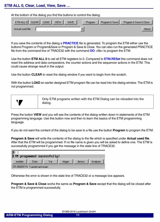
At the bottom of the dialog you find the buttons to control the dialog.
If you save the contents of the dialog a PRACTICE file is generated. To program the ETM either use the buttons Program or Program&Save or Program & Save & Close. You can also run the generated PRACTICE file from the command line of TRACE32 with the command DO <file> to program the ETM.
Use the button ETM ALL 0 to set all ETM registers to 0. Compared to ETM.RESet this command does not reset the address and data comparators, the counter actions and the sequencer actions in the ETM. This could cause strange result in the output.
Use the button CLEAR to reset the dialog window if you want to begin from the scratch.
With the button LOAD an earlier designed ETM program file can be read into the dialog window. The ETM is not programmed.
Press the button VIEW and you will see the contents of the dialog written down in statements of the ETM programming language. Use this button now and then to learn the basics of the ETM programming language.
If you do not want the content of the dialog to be save to a file use the button Program to program the ETM.
Program & Save will write the contents of the dialog to the file which is specified under Actual used file. After that the ETM will be programmed. If no file name is given you will be asked to define one. The ETM is successfully programmed if you get the message in the state line of TRACE32.
Otherwise the error is shown in the state line of TRACE32 or a message box appears.
Program & Save & Close works the same as Program & Save except that the dialog will be closed after the ETM is programmed successfully.
Only ETM programs written with the ETM Dialog can be reloaded into the dialog.
ARM-ETM Programming Dialog 11 ©1989-2018 Lauterbach GmbH

Definitions
Address/Range Definition
Up to three different address areas can be defined in this part of the dialog. This areas are later referenced by the logical names A-Range, B-Range or C-Range. The logical name AB-Range defines an area declared through the area A-Range combined with the area B-Range by LOGICAL AND.
Each area e.g. A-Range allows to define the address space through two different singular address parts. One of this part can hold a single address or an address range. The singular address parts are combined through LOGICAL OR to form the characteristic named A-Range.
If you don’t know how to specify an address or an address range click the V button.
With the appearing sub dialog a single address or any kind of range can be defined easily.
As you are familiar with the syntax of defining an address in TRACE32 just fill out the dialog.
ARM-ETM Programming Dialog 12 ©1989-2018 Lauterbach GmbH

The defined address area will be used to define the condition for carrying out an action in the main dialog.
If not address area is defined at the time you want to choose an address condition you will be asked to do so.
There is only one logic combination of AND or OR available at the ETM. Therefore you should be aware if you use the two address definition areas of a x-Range combined by “or” you could not use either a combination range like AB-/AC-/BC-Range nor a counter within the same event.
ARM-ETM Programming Dialog 13 ©1989-2018 Lauterbach GmbH

ARM-ETM Programming Dialog 14 ©1989-2018 Lauterbach GmbH

RD/WR.. and Data conditions are internally connected to Address/Range therefore you can use them without restrictions for the logical combination.
Be aware if you use RD/WR.. e.g FETCH with a special range e.g. A-Range you are not able to use A-Range with a different RD/WR.. condition e.g. ACCESS. The same applies if you use A-Range with condition DATA0/1.
ARM-ETM Programming Dialog 15 ©1989-2018 Lauterbach GmbH

Data Definition
Two different data values can be used to observe the data on the data bus. The data values are later referenced by the labels DATA0 and DATA1.
The data is defined through the value and the type. If you don’t know how to specify a data value just click the V button.
With the appearing subdialog a single data, a data range or a mask can be defined easily.
With the type you specify the width of the value. BYTE, WORD and LONG are available.
ARM-ETM Programming Dialog 16 ©1989-2018 Lauterbach GmbH

As you are familiar with the syntax of defining data in TRACE32 just fill out the dialog.
If there is no data defined at the time you want to use a data condition you will be asked to do so.
As the Data comparators of the ETM are strongly connected to the address range you cannot use a Data comparator without an address range. If you do so you get an error message.
ARM-ETM Programming Dialog 17 ©1989-2018 Lauterbach GmbH

Counter Definition
For controlling the flow two different counters can be defined. For each counter you can define the maximum value. The counters are referenced in the condition of an action by the labels COUNT0 and COUNT1.
After programming the ETM the counter is set to 100H. If no action is used to decrement the counter COUNT0 ( Decr Count 0 ) defined the counter is continuously decremented at full system clock speed.
To control the value of the counters the actions Decr Count0/1 and Restart Count0/1 are available.
If you use Trace with condition COUNT0/1 sampling begins when the counter COUNT0/1 is zero.If you use Trace with condition NOT COUNT0/1 sampling only takes place if the counter COUNT0/1 is bigger than zero.
ARM-ETM Programming Dialog 18 ©1989-2018 Lauterbach GmbH

Decr COUNT0/1 substracts 1 from the value of the counter COUNT0/1. Reload COUNT0/1 sets the value of the counter COUNT0/1 to the value specified in the definition.
If you don’t know how to define the value of a counter just click the V button.
As you are familiar with the syntax of defining counters in TRACE32 just fill out the dialog.
If there is no counter defined at the time you want to use a counter name in a condition or an action you will be asked to define it.
If you don’t use Decr Count x to set the counter or you don’t use an event for this action the counter decrements at full system clock speed. For this case it is recommended to use the Reload COUNT x action to reload the counter at a definite point otherwise the counter will be run to zero till you start the program run.
ARM-ETM Programming Dialog 19 ©1989-2018 Lauterbach GmbH

Examples
Example 1: Selective Trace on an Address Range
Click here to open theDefine Address Window
2. Click here to choose
out of the list of available classes
3. Type in the base addressof the range
4. Type in the end address of the range
1. Click here to select
5. Press OK button
the radio buttonfor Range
a memory class
ARM-ETM Programming Dialog 20 ©1989-2018 Lauterbach GmbH

ARM-ETM Programming Dialog 21 ©1989-2018 Lauterbach GmbH

Example 2: Selective Trace on an Address Range defined through a Symbol
Click here to open theDefine Address Window
Press the V button
Click here to select the radio buttonfor HLL-Range
Select the symbol by a double click
ARM-ETM Programming Dialog 22 ©1989-2018 Lauterbach GmbH

ARM-ETM Programming Dialog 23 ©1989-2018 Lauterbach GmbH

Example 3: Selective Trace on Access to a Symbol
Click here to open the
Click here to browse throughthe symbol data base
Select the symbol by adouble click
Define Address Window
ARM-ETM Programming Dialog 24 ©1989-2018 Lauterbach GmbH

ARM-ETM Programming Dialog 25 ©1989-2018 Lauterbach GmbH

Example 4: Trace the Entrance and Exit of Function Sieve
Define the begin of function sieve Define the end of function sieve
ARM-ETM Programming Dialog 26 ©1989-2018 Lauterbach GmbH

Example 5: Trace the first 200H Cycles in Function Sieve
Define Counter Count0
ARM-ETM Programming Dialog 27 ©1989-2018 Lauterbach GmbH

Example 6: Trace all, when Function Sieve is reached goto Level 1 and stop Sampling and Debugging after 5 Cycles
Define the begin of functionsieve in A-Range
Define the max value 30 for counting the cycles in COUNT0
Change level if sieve is reached
Reload COUNT0 when sieve is reached
Subtract one COUNT0 every cycleStop sampling when COUNT0 reaches 0
Sampling starts here
Sampling stops here
ARM-ETM Programming Dialog 28 ©1989-2018 Lauterbach GmbH