Embed Size (px)
Citation preview
ARM HOW-TO GUIDE
Interfacing Stepper
Motor with LPC2148
Join the Technical Community Today!
http://www.pantechsolutions.net
Contents at a Glance
ARM7 LPC2148 Slicker Board ........................................... 3
Stepper Motor ................................................................. 3
Interfacing Stepper Motor ............................................... 4
Interfacing Stepper Motor with LPC2148 .......................... 5
Pin Assignment with LPC2148 .......................................... 5
Circuit Diagram to Interface Stepper Motor with LPC2148..
......................................................................... …………….6
Source Code .................................................................... 6
C Program to control stepper motor using LPC2148 .......... 7
Testing the Stepper Motor with LPC2148 ......................... 9
General Information ...................................................... 10
Join the Technical Community Today!
http://www.pantechsolutions.net
ARM7 LPC2148 Slicker Board
The ARM7 LPC2148 Slicker board is specifically
designed to help students to master the required skills in
the area of embedded systems. The kit is designed in such
way that all the possible features of the microcontroller will
be easily used by the students. The kit supports in system
programming (ISP) which is done through serial port.
NXP’s ARM7 (LPC2148), ARM Slicker Kit is proposed to
smooth the progress of developing and debugging of
various designs encompassing of High speed 32-bit
Microcontrollers.
Stepper Motor
A stepper motor is a brushless, synchronous electric
motor that converts digital pulses into mechanical shaft
rotation. Every revolution of the stepper motor is divided
into a discrete number of steps, and the motor must be sent
a separate pulse for each step.

Join the Technical Community Today!
http://www.pantechsolutions.net
Interfacing Stepper Motor
Fig. 1 shows how to interface the Stepper Motor to
microcontroller. As you can see the stepper motor is
connected with Microcontroller output port pins through a
ULN2803A array. So when the microcontroller is giving
pulses with particular frequency to ULN2803A, the motor is
rotated in clockwise or anticlockwise.
Fig. 1 Interfacing Stepper Motor to Microcontroller
Join the Technical Community Today!
http://www.pantechsolutions.net
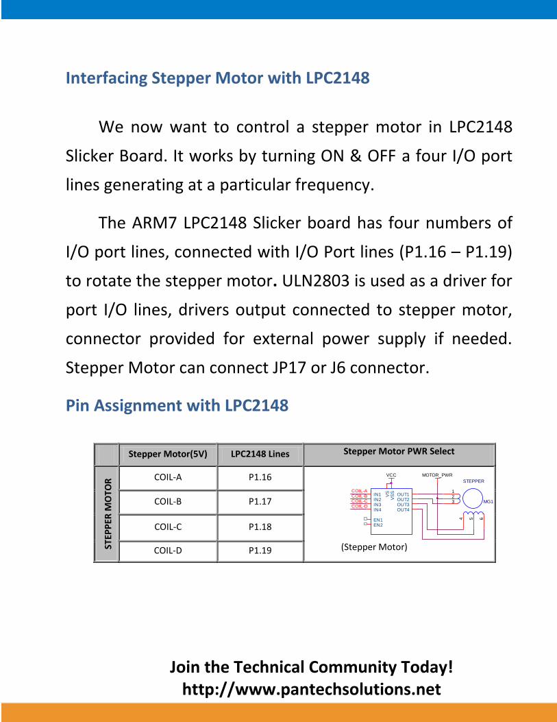
Interfacing Stepper Motor with LPC2148
We now want to control a stepper motor in LPC2148
Slicker Board. It works by turning ON & OFF a four I/O port
lines generating at a particular frequency.
The ARM7 LPC2148 Slicker board has four numbers of
I/O port lines, connected with I/O Port lines (P1.16 – P1.19)
to rotate the stepper motor. ULN2803 is used as a driver for
port I/O lines, drivers output connected to stepper motor,
connector provided for external power supply if needed.
Stepper Motor can connect JP17 or J6 connector.
Pin Assignment with LPC2148
Stepper Motor(5V) LPC2148 Lines Stepper Motor PWR Select
STEP
PER
MO
TOR
COIL-A P1.16
(Stepper Motor)
COIL-B P1.17
COIL-C P1.18
COIL-D P1.19
IN1IN2IN3IN4
EN1
OUT1OUT2OUT3OUT4
VS
SV
S
EN2
MG1
STEPPER
123
4 5 6
MOTOR_PWRVCC
COIL-CCOIL-BCOIL-A
COIL-D
Join the Technical Community Today!
http://www.pantechsolutions.net
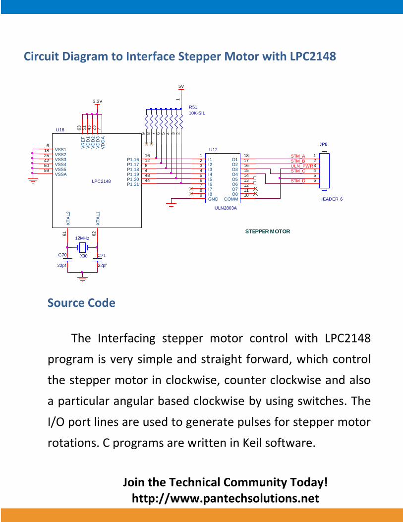
Circuit Diagram to Interface Stepper Motor with LPC2148
Source Code
The Interfacing stepper motor control with LPC2148
program is very simple and straight forward, which control
the stepper motor in clockwise, counter clockwise and also
a particular angular based clockwise by using switches. The
I/O port lines are used to generate pulses for stepper motor
rotations. C programs are written in Keil software.
5V
ULN_PWR
STEPPER MOTOR
STM_A
STM_D
STM_C
JP8
HEADER 6
123456
U12
ULN2803A
I11
I22
I33
I44
I55
I66
I77
I88
GND9
O118
O217
O316
O415
O514
O613
O712
O811
COMM10
R51
10K-SIL
123456789
STM_B
3.3V
C70
22pf
C71
22pf
X30
12MHz
LPC2148
U16
VSS16 V
DD
A7
VSS218
VD
D3
23
VSS325
VD
D2
43
VSS442
VR
EF
63
XT
AL1
62
XT
AL2
61
VSSA59
VD
D1
51
VSS550
P1.1616
P1.1712
P1.188
P1.194
P1.2048
P1.2144

Join the Technical Community Today!
http://www.pantechsolutions.net
C Program to control stepper motor using LPC2148 ***************************************************************************************
Title : Program to control stepper motor rotations ***************************************************************************************
#include<LPC214x.h> // Define LPC2148 Header File
#include <stdio.h>
#define COIL_A 16
void motor_ccw(void);
void delay(int);
unsigned char STEP[] = {0x09, 0x08, 0x0C, 0x04, 0x06,
0x02, 0x03, 0x01};
void main(void)
{
unsigned char i = 0;
PINSEL2 &= 0xFFFFFFF3; // P1.16 - P1.31 as GPIO
IODIR1 = 0x000F0000; // P1.16 - P1.19 as Output
while(1)
{
IOCLR0 = 0xFF << COIL_A;
motor_ccw(); // Stepper Motor counter clockwise
}
}
Join the Technical Community Today!
http://www.pantechsolutions.net
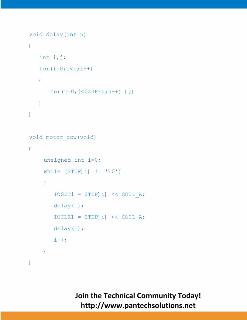
void delay(int n)
{
int i,j;
for(i=0;i<n;i++)
{
for(j=0;j<0x3FF0;j++) {;}
}
}
void motor_ccw(void)
{
unsigned int i=0;
while (STEP[i] != '\0')
{
IOSET1 = STEP[i] << COIL_A;
delay(1);
IOCLR1 = STEP[i] << COIL_A;
delay(1);
i++;
}
}
Join the Technical Community Today!
http://www.pantechsolutions.net
To compile the above C code you need the KEIL
software. They must be properly set up and a project with
correct settings must be created in order to compile the
code. To compile the above code, the C file must be added
to the project.
In KEIL, you want to develop or debug the project
without any hardware setup. You must compile the code for
generating HEX file. In debugging Mode, you want to check
the port output without LPC2148 Slicker Board.
The Flash Magic software is used to download the hex
file into your microcontroller IC LPC2148 through UART0.
Testing the Stepper Motor with LPC2148
Give +3.3V power supply to LPC2148 Slicker Board; the
Stepper Motor is connected with LPC2148 Slicker Board.
When the program is downloading into LPC2148 in Slicker
Board, the LED output is working that the LED is ON some
time period and the LED is OFF some other time period for a
particular frequency. Now, the stepper motor is rotating.
Join the Technical Community Today!
http://www.pantechsolutions.net
In this code, the Stepper Motor is running in clockwise
direction automatically. If you are not reading any output
from LED, then you just check the jumper connections &
check the LED is working.
If the stepper motor is not rotating then check the
motor connections. Otherwise you just check the code with
debugging mode in KEIL. If you want to see more details
about debugging just see the videos in below link.
How to Create & Debug a Project in KEIL.
General Information
For proper working use the components of exact values
as shown in Circuit file. Wherever possible use new
components.
Solder everything in a clean way. A major problem
arises due to improper soldering, solder jumps and
loose joints.
Use the exact value crystal shown in schematic.
Join the Technical Community Today!
http://www.pantechsolutions.net
More instructions are available in the following articles,
User Manual of LPC2148 Slicker Board.
Tutorial of how to create & Debug a project in
KEIL.
Interfacing LED with LPC2148.
Interfacing switch with LPC2148.

Join the Technical Community Today!
http://www.pantechsolutions.net
Pantech solutions creates information packed technical
documents like this one every month. And our website is a rich
and trusted resource used by a vibrant online community of
more than 1,00,000 members from organization of all shapes
and sizes.
Did you enjoy the read?

Join the Technical Community Today!
http://www.pantechsolutions.net
What do we sell?
Our products range from Various Microcontroller
development boards, DSP Boards, FPGA/CPLD boards,
Communication Kits, Power electronics, Basic electronics,
Robotics, Sensors, Electronic components and much more . Our
goal is to make finding the parts and information you need
easier and affordable so you can create awesome projects and
training from Basic to Cutting edge technology.