Embed Size (px)
Citation preview

1
ARM Instruction Set
ARMAdvanced RISC Machines

2
Content Coverage

3
Main features of the ARM Instruction Set All instructions are 32 bits long. Most instructions execute in a single cycle. Every instruction can be conditionally executed. A load/store architecture
Data processing instructions act only on registers Three operand format Combined ALU and shifter for high speed bit manipulation
Specific memory access instructions with powerful auto-indexing addressing modes.
32 bit and 8 bit data types and also 16 bit data types on ARM Architecture v4.
Flexible multiple register load and store instructions
Instruction set extension via coprocessors
4
Accessing Registers using ARM Instructions
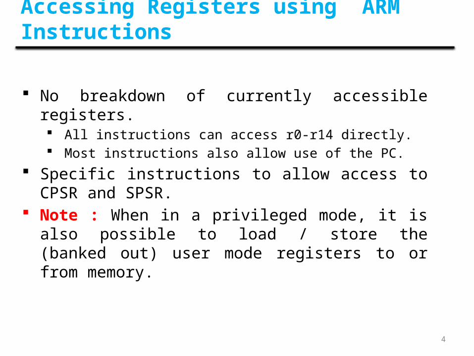
No breakdown of currently accessible registers. All instructions can access r0-r14 directly. Most instructions also allow use of the PC.
Specific instructions to allow access to CPSR and SPSR. Note : When in a privileged mode, it is also possible to
load / store the (banked out) user mode registers to or from memory.

5
Condition Flags
Flags Logical Instruction Arithmetic Instruction
Negative No meaning Bit 31 of the result has been set(N=‘1’) Indicates a negative number in
signed operations
Zero Result is all zeroes Result of operation was zero(Z=‘1’)
Carry After Shift operation Result was greater than 32 bits(C=‘1’) ‘1’ was left in carry flag
oVerflow No meaning Result was greater than 31 bits(V=‘1’) Indicates a possible corruption of
the sign bit in signed numbers

6
The Program Counter (R15)
• When the processor is executing in ARM state:– All instructions are 32 bits in length– All instructions must be word aligned– Therefore the PC value is stored in bits [31:2] with bits [1:0] equal
to zero (as instruction cannot be half-word or byte aligned).
• R14 is used as the subroutine link register (LR) and stores the return address when Branch with Link operations are performed, calculated from the PC.
• Thus to return from a linked branch– MOV r15,r14
or– MOV pc,lr
When used in relation to the ARMByte means 8 bitsHalfword means 16 bits (two bytes)Word means 32 bits (four bytes)

7
Exception Handling and the Vector Table
• When an exception occurs, the core:– Copies CPSR into SPSR_<mode>– Sets appropriate CPSR bits
If core implements ARM Architecture 4T and is currently in Thumb state, then
ARM state is entered. Mode field bits Interrupt disable flags if appropriate.
– Maps in appropriate banked registers– Stores the “return address” in LR_<mode>– Sets PC to vector address
• To return, exception handler needs to:– Restore CPSR from SPSR_<mode>– Restore PC from LR_<mode>
0x00000000
0x0000001C
0x00000018
0x00000014
0x00000010
0x0000000C
0x00000008
0x00000004
Reset
Undefined Instruction
FIQ
IRQ
Reserved
Data Abort
Prefetch Abort
Software Interrupt
8
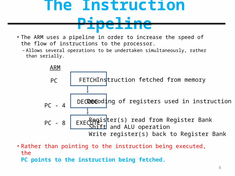
The Instruction Pipeline• The ARM uses a pipeline in order to increase the speed of the flow of
instructions to the processor.– Allows several operations to be undertaken simultaneously, rather than serially.
• Rather than pointing to the instruction being executed, the PC points to the instruction being fetched.
FETCH
DECODE
EXECUTE
Instruction fetched from memory
Decoding of registers used in instruction
Register(s) read from Register BankShift and ALU operationWrite register(s) back to Register Bank
PC
PC - 4
PC - 8
ARM
9
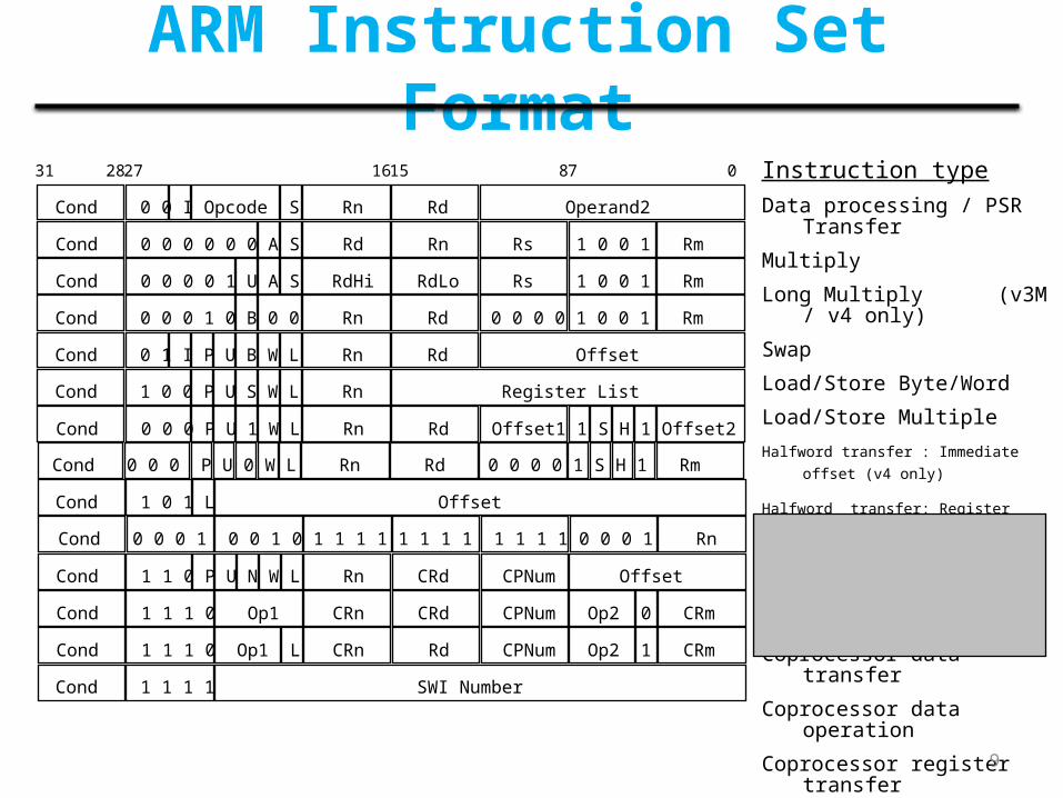
ARM Instruction Set FormatInstruction typeData processing / PSR Transfer
Multiply
Long Multiply (v3M / v4 only)
Swap
Load/Store Byte/Word
Load/Store Multiple
Halfword transfer : Immediate offset (v4 only)
Halfword transfer: Register offset (v4 only)
Branch
Branch Exchange (v4T only)
Coprocessor data transfer
Coprocessor data operation
Coprocessor register transfer
Software interrupt
Cond 0 0 I Opcode S Rn Rd Operand2
Cond 0 0 0 0 0 0 A S Rd Rn Rs 1 0 0 1 Rm
Cond 0 0 0 1 0 B 0 0 Rn Rd 0 0 0 0 1 0 0 1 Rm
Cond 0 1 I P U B W L Rn Rd Offset
Cond 1 0 0 P U S W L Rn Register List
Cond 0 0 0 0 1 U A S RdHi RdLo Rs 1 0 0 1 Rm
Cond 0 0 0 P U 1 W L Rn Rd Offset1 1 S H 1 Offset2
Cond 1 0 1 L Offset
Cond 1 1 0 P U N W L Rn CRd CPNum Offset
Cond 1 1 1 0 Op1 CRn CRd CPNum Op2 0 CRm
Cond 1 1 1 0 Op1 L CRn Rd CPNum Op2 1 CRm
Cond 1 1 1 1 SWI Number
Cond 0 0 0 1 0 0 1 0 1 1 1 1 1 1 1 1 1 1 1 1 0 0 0 1 Rn
Cond 0 0 0 P U 0 W L Rn Rd 0 0 0 0 1 S H 1 Rm
31 2827 1615 87 0

10
Conditional Execution
• Most instruction sets only allow branches to be executed conditionally.
• However by reusing the condition evaluation hardware, ARM effectively increases number of instructions.
– All instructions contain a condition field which determines whether the CPU will execute them.
– Non-executed instructions soak up 1 cycle.• Still have to complete cycle so as to allow fetching and decoding of following
instructions.
• This removes the need for many branches, which stall the pipeline (3 cycles to refill).
– Allows very dense in-line code, without branches.– The Time penalty of not executing several conditional instructions is
frequently less than overhead of the branch or subroutine call that would otherwise be needed.

11
The Condition Fieldcond
0272831
Opcode[31:28]
Mnemonicextension Interpretation Status flag state for execution
0000 EQ Equal / equals zero Z set
0001 NE Not equal Z clear
0010 CS/HS Carry set / unsigned higher or some C set
0011 CC/LO Carry clear / unsigned lower C clear
0100 MI Minus / negative N set
0101 PL Plus / positive or zero N clear
0110 VS Overflow V set
0111 VC No overflow V clear
1000 HI Unsigned higher C set and Z clear
1001 LS Unsigned lower or same C clear or Z set
1010 GE Signed greater than or equal N equals V
1011 LT Signed less than N is not equal to V
1100 GT Signed greater than Z clear and N equals V
1101 LE Signed less than or equal Z sets or N is not equal to V
1110 AL Always any
1111 NV Never (do not use!) none
12
Using and updating the Condition Field
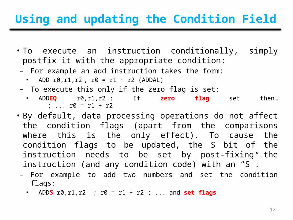
• To execute an instruction conditionally, simply postfix it with the appropriate condition:
– For example an add instruction takes the form:• ADD r0,r1,r2 ; r0 = r1 + r2 (ADDAL)
– To execute this only if the zero flag is set:• ADDEQ r0,r1,r2 ; If zero flag set then…
; ... r0 = r1 + r2
• By default, data processing operations do not affect the condition flags (apart from the comparisons where this is the only effect). To cause the condition flags to be updated, the S bit of the instruction needs to be set by post-fixing the instruction (and any condition code) with an “S”.
– For example to add two numbers and set the condition flags:• ADDS r0,r1,r2 ; r0 = r1 + r2 ; ... and
set flags
13
ARM instructions by instruction class
1. Data Processing Instructions
2. Branch Instructions
3. Load-Store Instructions
4. Software Interrupt Instruction
5. Program Status Register Instructions

14
ARM instructions by instruction class
1. Data Processing Instructions
2. Branch Instructions
3. Load-Store Instructions
4. Software Interrupt Instruction
5. Program Status Register Instructions

15
Data Processing Instructions
i. Move Instructionsii. Barrel Shifteriii. Arithmetic Instructionsiv. Using the Barrel Shifter with Arithmetic Instructionsv. Logical Instructionsvi. Comparison Instructionsvii. Multiply Instructions

16
• The basic encoding format for the instructions, such as Load, Store, Move, Arithmetic, and Logic instructions, is shown below
• An instruction specifies a conditional execution code (Condition), the OP code, two or three registers (Rn, Rd, and Rm), and some other information

17
cond 0 0 operand 2# opcode S Rn Rd
31 28 27 26 25 24 21 20 19 16 15 12 11 0
destination register
first operand register
set condition codes
arithmetic/logic function
8-bit immediate1
25 11 8 7 0
#rot
Rm
11 7 6 5 4 3 0
#shift
Rm
0
25
11 8 7 6 5 4 3 0
Rs
Sh 0
10 Sh
immediate alignment
immediate shift length
shift type
second operand register
register shift length
Data Processing Instruction Format

18
Move InstructionsMove is the simplest ARM instruction. It copies N into a destination register Rd, where N is a register or immediate value. This instruction is useful for setting initial values and transferring data between registers.
Syntax: <instruction>{<cond>}{S} Rd, N
• Usually it is a register Rm or a constant preceded by #.
MOV Move a 32-bit value into a register Rd = N
MVN move the NOT of the 32-bit value into a register
Rd =∼N

19
Example 1This example shows a simple move instruction. The MOV instruction takes the contents of register r5 and copies them into register r7, in this case, taking the value 5, and overwriting the value 8 in register r7.
PRE r5 = 5r7 = 8
MOV r7, r5 ; let r7 = r5 (comment)
POST r5 = 5r7 = 5

20
Example 2Loading the constant 0xff00ffff into register r0 using an MVN.
PRE none...
MVN r0, #0x00ff0000
POST r0 = 0xff00ffff

21
Data Processing Instructions
i. Move Instructionsii. Barrel Shifteriii. Arithmetic Instructionsiv. Using the Barrel Shifter with Arithmetic Instructionsv. Logical Instructionsvi. Comparison Instructionsvii. Multiply Instructions

22
Barrel ShifterMOV instruction where N is a simple register. But N can be more than just a register or immediate value; it can also be a register Rm that has been preprocessed by the barrel shifter prior to being used by a data processing instruction.
Data processing instructions are processed within the arithmetic logic unit (ALU). A unique and powerful feature of the ARM processor is the ability to shift the 32-bit binary pattern in one of the source registers left or right by a specific number of positions before it enters the ALU. This shift increases the power and flexibility of many data processing operations.
Pre-processing or shift occurs within the cycle time of the instruction. This is particularly useful for loading constants into a register and achieving fast multiplies or division by a power of 2.
23
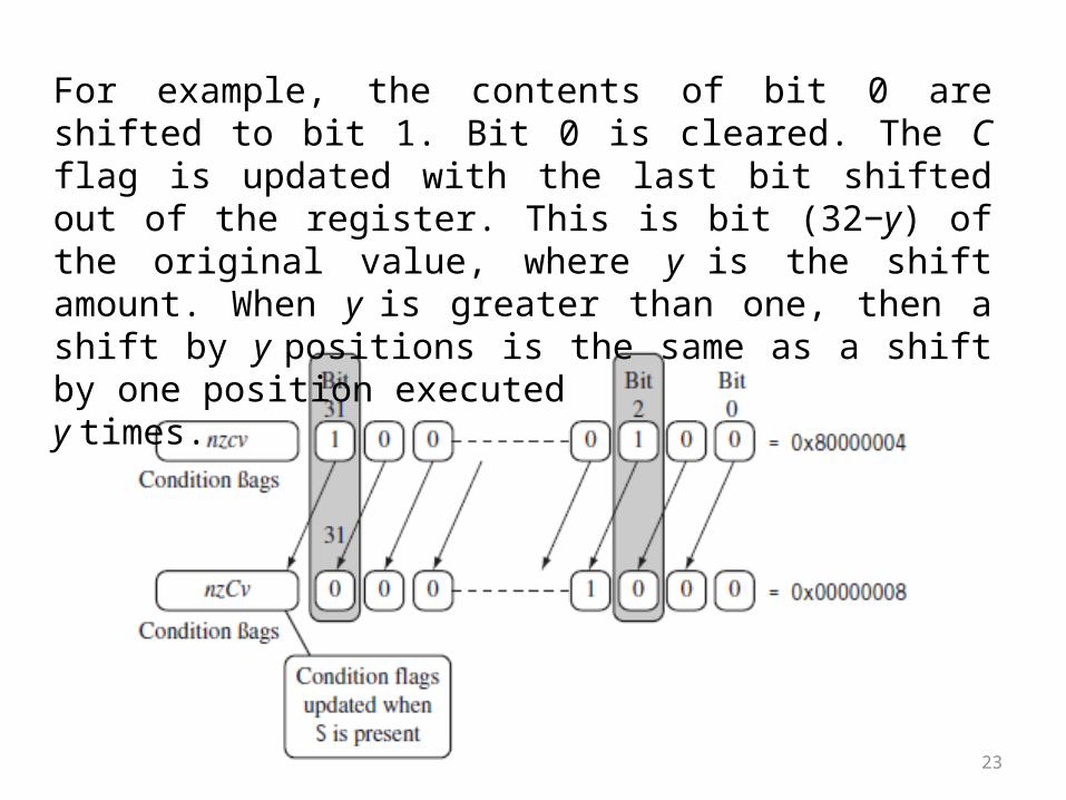
For example, the contents of bit 0 are shifted to bit 1. Bit 0 is cleared. The C flag is updated with the last bit shifted out of the register. This is bit (32−y) of the original value, where y is the shift amount. When y is greater than one, then a shift by y positions is the same as a shift by one position executedy times.
24
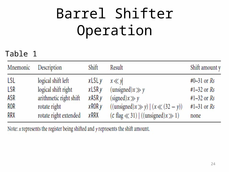
Barrel Shifter Operation
Table 1

25
• Shifts left by the specified amount (multiplies by powers of two) e.g.
LSL #5 = multiply by 32
Barrel Shifter - Left Shift
Logical Shift Left (LSL)
DestinationCF 0
26
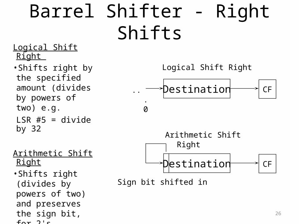
Logical Shift Right •Shifts right by the specified amount (divides by powers of two) e.g. LSR #5 = divide by 32
Arithmetic Shift Right •Shifts right (divides by powers of two) and preserves the sign bit, for 2's complement operations. e.g. ASR #5 = divide by 32
Barrel Shifter - Right Shifts
Destination CF
Destination CF
Logical Shift Right
Arithmetic Shift Right
...0
Sign bit shifted in

27
Barrel Shifter - Rotations Rotate Right (ROR)• Similar to an ASR
but the bits wrap around as they leave the LSB and appear as the MSB.e.g. ROR #5
•Note the last bit rotated is also used as the Carry Out.
Rotate Right Extended (RRX)• This operation uses the
CPSR C flag as a 33rd bit. •Rotates right by 1 bit.
Encoded as ROR #0.
Destination CF
Rotate Right
Destination CF
Rotate Right through Carry

28
Using the Barrel Shifter:The Second Operand
* Immediate value• 8 bit number• Can be rotated right through
an even number of positions.
• Assembler will calculate rotate for you from constant.
• Register, optionally with shift operation applied.
• Shift value can be either be:– 5 bit unsigned integer– Specified in bottom byte of
another register.
Operand 1
Result
ALU
Barrel Shifter
Operand 2

29
Second Operand :Shifted Register
• The amount by which the register is to be shifted is contained in either: – the immediate 5-bit field in the instruction
• NO OVERHEAD • Shift is done for free - executes in single cycle.
– the bottom byte of a register (not PC)• Then takes extra cycle to execute• ARM doesn’t have enough read ports to read 3 registers at
once.• Then same as on other processors where shift is
separate instruction.
• If no shift is specified then a default shift is applied: LSL #0– i.e. barrel shifter has no effect on value in register.

30
Example 3We apply a logical shift left (LSL) to register Rm before moving it to the destination register. This is the same as applying the standard C language shift operator to the register. The MOV instruction copies the shift operator result N into register Rd.
PRE r5 = 5r7 = 8
MOV r7, r5, LSL #2 ; let r7 = r5*4 = (r5 << 2)
POST r5 = 5r7 = 20
The example multiplies register r5 by four and then places the result into register r7.

31
Table 2

32
Example 4This example of a MOVS instruction shifts register r1 left by one bit. This multiplies register r1 by a value 21.
PRE cpsr = nzcvqiFt_USERr0 = 0x00000000r1 = 0x80000004
MOVS r0, r1, LSL #1
POST cpsr = nzCvqiFt_USERr0 = 0x00000008r1 = 0x80000004
As you can see, the C flag is updated in the cpsr because the S suffix is present in the instruction mnemonic.

33
Data Processing Instructions
i. Move Instructionsii. Barrel Shifteriii. Arithmetic Instructionsiv. Using the Barrel Shifter with Arithmetic Instructionsv. Logical Instructionsvi. Comparison Instructionsvii. Multiply Instructions

34
• The arithmetic instructions implement addition and subtraction of 32-bit signed and unsigned values.
Syntax: <instruction>{<cond>}{S} Rd, Rn, N
Arithmetic Instructions
N is the result of the shifter operation.

35
Example 5This simple subtract instruction subtracts a value stored in register r2 from a value stored in register r1. The result is stored in register r0.
PRE r0 = 0x00000000r1 = 0x00000002r2 = 0x00000001
SUB r0, r1, r2
POST r0 = 0x00000001
Syntax: <instruction>{<cond>}{S} Rd, Rn, N
36
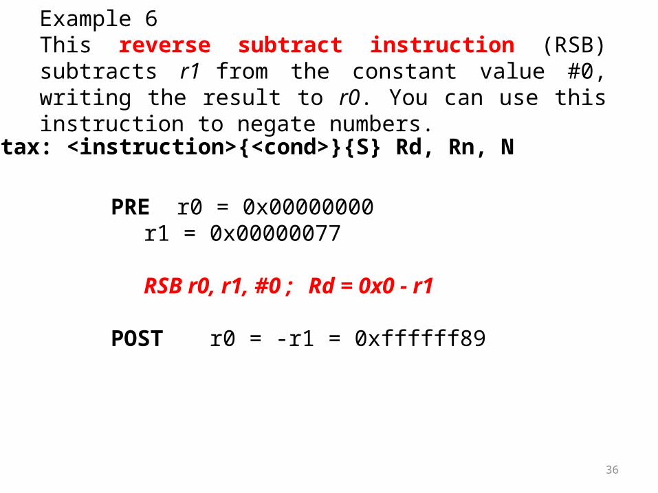
Example 6This reverse subtract instruction (RSB) subtracts r1 from the constant value #0, writing the result to r0. You can use this instruction to negate numbers.
PRE r0 = 0x00000000r1 = 0x00000077
RSB r0, r1, #0 ; Rd = 0x0 - r1
POST r0 = -r1 = 0xffffff89
Syntax: <instruction>{<cond>}{S} Rd, Rn, N

37
Example 7The SUBS instruction is useful for decrementing loop counters. In this example we subtract the immediate value one from the value one stored in register r1. The result value zero is written to register r1. The cpsr is updated with the Z flags being set.
PRE cpsr = nzCvqiFt_USERr1 = 0x00000001
SUBS r1, r1, #1
POST cpsr = nZCvqiFt_USERr1 = 0x00000000
Syntax: <instruction>{<cond>}{S} Rd, Rn, N

38
Data Processing Instructions
i. Move Instructionsii. Barrel Shifteriii. Arithmetic Instructionsiv. Using the Barrel Shifter with Arithmetic Instructionsv. Logical Instructionsvi. Comparison Instructionsvii. Multiply Instructions

39
• The wide range of second operand shifts available on arithmetic and logical instructions is a very powerful feature of the ARM instruction set.
Using the Barrel Shifter with Arithmetic Instructions

40
Example 8Register r1 is first shifted one location to the left to give the value of twice r1. The ADD instruction then adds the result of the barrel shift operation to register r1. The final result transferred into register r0 is equal to three times the value stored in register r1.
PRE r0 = 0x00000000r1 = 0x00000005
ADD r0, r1, r1, LSL #1
POST r0 = 0x0000000fr1 = 0x00000005
Syntax: <instruction>{<cond>}{S} Rd, Rn, N

41
Data Processing Instructions
i. Move Instructionsii. Barrel Shifteriii. Arithmetic Instructionsiv. Using the Barrel Shifter with Arithmetic Instructionsv. Logical Instructionsvi. Comparison Instructionsvii. Multiply Instructions

42
Logical Instructions
• Logical instructions perform bitwise logical operations on the two source registers.
Syntax: <instruction>{<cond>}{S} Rd, Rn, N
r0:= r1ANDr2
r0:= r1ORr2
r0:= r1XORr2
r0:= r1AND(NOT r2), bit clear

43
Example 9 This example shows a logical OR operation between registers r1 and r2. r0 holds the result.
PRE r0 = 0x00000000r1 = 0x02040608r2 = 0x10305070
ORR r0, r1, r2
POST r0 = 0x12345678

44
Example 10 This example shows a more complicated logical instruction called BIC, which carries out a logical bit clear.
PRE r1 = 0b1111r2 = 0b0101
BIC r0, r1, r2; Rd = Rn AND NOT(N)
POST r0 = 0b1010
The logical instructions update the cpsr flags only if the S suffix is present. These instructions can use barrel-shifted second operands in the same way as the arithmeticinstructions.

45
• The comparison instructions are used to compare or test a register with a 32-bit value.
• They update the cpsr flag bits according to the result, but do not affect other registers. After the bits have been set, the information can then be used to change program flow by using conditional execution.
• You do not need to apply the S suffix for comparison instructions to update the flags.
Comparison Instructions

46
Syntax: <instruction>{<cond>} Rn, N
• The CMP is effectively a subtract instruction with the result discarded; similarly the TST instruction is a logical AND operation, and TEQ is a logical exclusive OR operation.
• For each, the results are discarded but the condition bits are updated in the cpsr. It is important to understand that comparison instructions only modify the condition flags of the cpsr and do not affect the registers being compared.

47
Example 11This example shows a CMP comparison instruction. You can see that both registers, r0 and r9, are equal before executing the instruction. The value of the z flag prior to execution is 0 and is represented by a lowercase z. After execution the z flag changes to 1 or an uppercase Z. This change indicates equality.
PRE cpsr = nzcvqiFt_USERr0 = 4r9 = 4
CMP r0, r9
POST cpsr = nZcvqiFt_USER

48
• The multiply instructions multiply the contents of a pair of registers and, depending upon the instruction, accumulate the results in with another register.
• The long multiplies accumulate onto a pair of registers representing a 64-bit value.
• The final result is placed in a destination register or a pair of registers.
Multiply Instructions
49
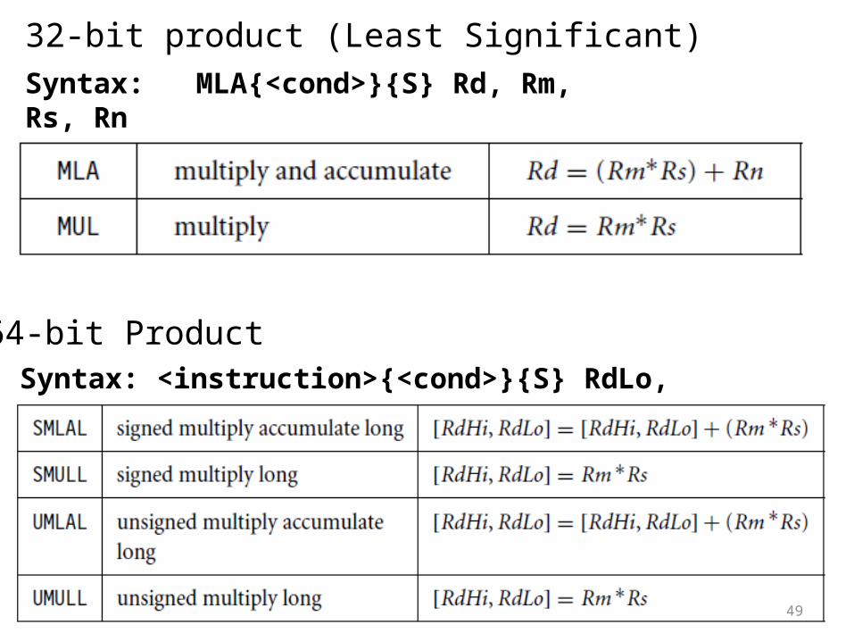
Syntax: MLA{<cond>}{S} Rd, Rm, Rs, RnMUL{<cond>}{S} Rd, Rm, Rs
Syntax: <instruction>{<cond>}{S} RdLo, RdHi, Rm, Rs
64-bit Product
32-bit product (Least Significant)

50
Example 12This example shows a simple multiply instruction that multiplies registers r1 and r2 together and places the result into register r0. In this example, register r1 is equal to the value 2, and r2 is equal to 2. The result, 4, is then placed into register r0.
PRE r0 = 0x00000000r1 = 0x00000002r2 = 0x00000002
MUL r0, r1, r2 ; r0 = r1*r2
POST r0 = 0x00000004r1 = 0x00000002r2 = 0x00000002
The long multiply instructions (SMLAL, SMULL, UMLAL, and UMULL) produce a 64-bit result. The result is too large to fit a single 32-bit register so the result is placed in two registers labeled RdLo and RdHi. RdLo holds the lower 32 bits of the 64-bit result, and RdHi holds the higher 32 bits of the 64-bit result. Example 3.12 shows an example of a long unsigned multiply instruction.

51
Example 13The instruction multiplies registers r2 and r3 and places the result into register r0 and r1. Register r0 contains the lower 32 bits, and register r1 contains the higher 32 bits of the 64-bit result.
PRE r0 = 0x00000000r1 = 0x00000000r2 = 0xf0000002r3 = 0x00000002
UMULL r0, r1, r2, r3 ; [r1,r0] = r2*r3
POST r0 = 0xe0000004 ; = RdLor1 = 0x00000001 ; = RdHi

52
ARM instructions by instruction class
1. Data Processing Instructions
2. Branch Instructions
3. Load-Store Instructions
4. Software Interrupt Instruction
5. Program Status Register Instructions

53
• A branch instruction changes the flow of execution or is used to call a routine. This type of instruction allows programs to have subroutines, if-then-else structures, and loops.
• The change of execution flow forces the program counter pc to point to a new address.
Branch Instructions

54
Syntax: B{<cond>} labelBL{<cond>} labelBX{<cond>} RmBLX{<cond>} label | Rm
The address label is stored in the instruction as a signed pc-relative offset and must be within approximately 32 MB of the branch instruction. T refers to the Thumb bit in the cpsr. When instructions set T, the ARM switches to Thumb state.
55
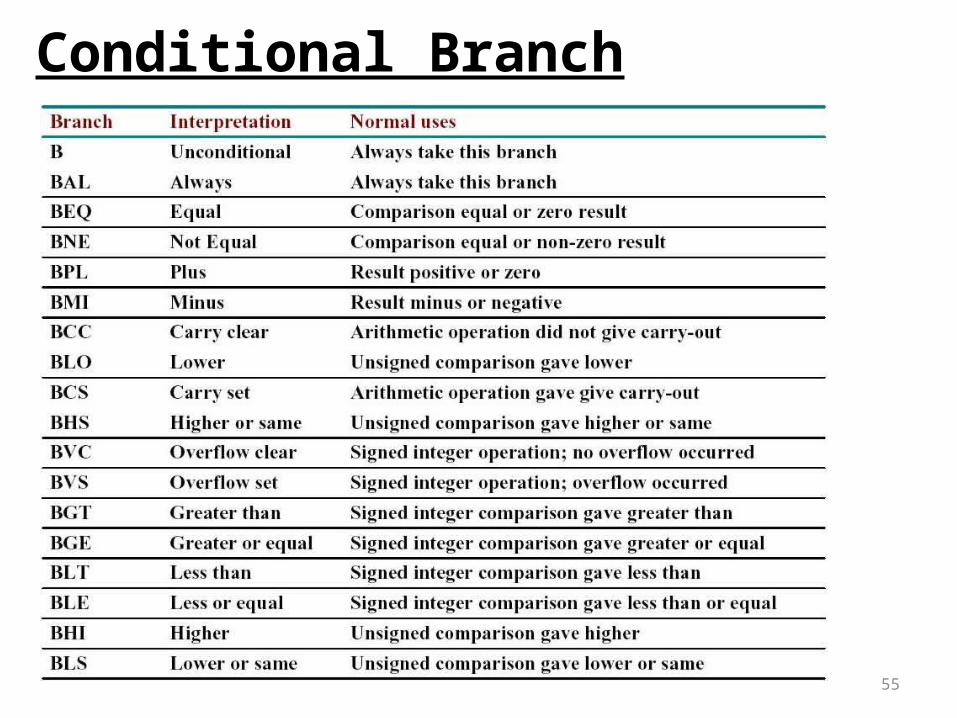
Conditional Branch

56
Example 14This example shows a forward and backward branch. Because these loops are address specific, we do not include the pre- and post-conditions. The forward branch skips three instructions. The backward branch creates an infinite loop.
B forwardADD r1, r2, #4ADD r0, r6, #2ADD r3, r7, #4
forwardSUB r1, r2, #4
backwardADD r1, r2, #4SUB r1, r2, #4ADD r4, r6, r7B backward
Infinite loopUnconditional Jump
Branches are used to change execution flow. Most assemblers hide the details of a branch instruction encoding by using labels. In this example, forward and backward are the labels. The branch labels are placed at the beginning of the line and are used to mark an address that can be used later by the assembler to calculate the branch offset.

57
Example 15The branch with link, or BL, instruction is similar to the B instruction but overwrites the link register lr with a return address. It performs a subroutine call. This example shows a simple fragment of code that branches to a subroutine using the BL instruction. To return from a subroutine, you copy the link register to the pc.
BL subroutine ; branch to subroutineCMP r1, #5 ; compare r1 with 5MOVEQ r1, #0 ; if (r1==5) then r1 = 0:
subroutine<subroutine code>MOV pc, lr ; return by moving pc = lr
The branch exchange (BX) and branch exchange with link (BLX) are the third type of branch instruction. The BX instruction uses an absolute address stored in register Rm. It is primarily used to branch to and from Thumb code. The T bit in the cpsr is updated by the least significant bit of the branch register. Similarly the BLX instruction updates the T bit of the cpsr with the least significant bit and additionally sets the link register with the return address.

58
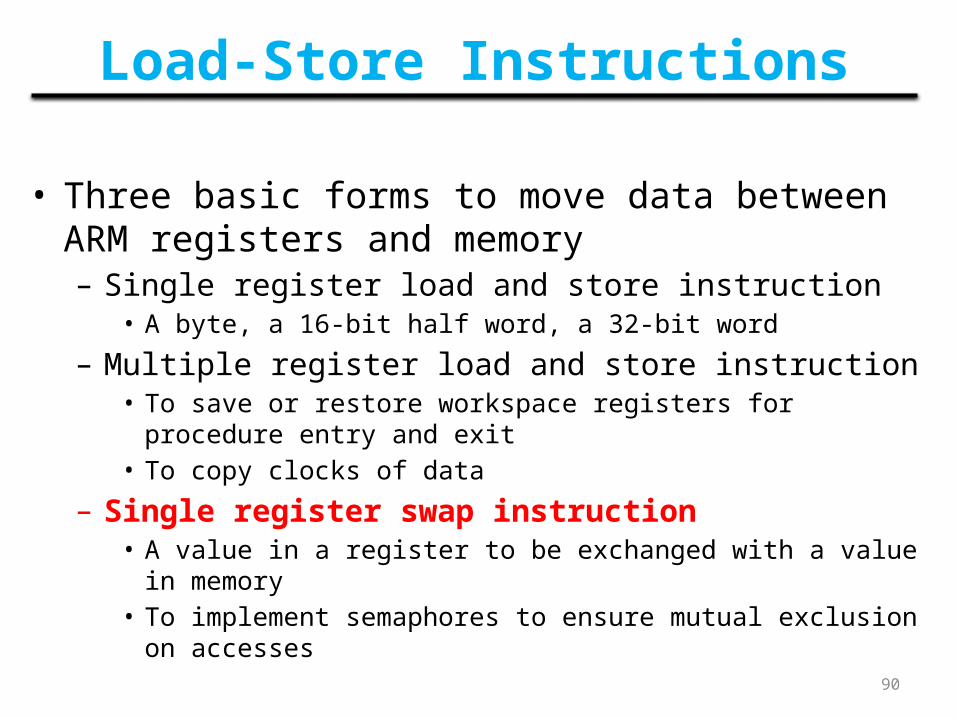
Load-Store Instructions• Three basic forms to move data between ARM registers
and memory– Single register load and store instruction
• A byte, a 16-bit half word, a 32-bit word
– Multiple register load and store instruction• To save or restore workspace registers for procedure entry and exit• To copy clocks of data
– Single register swap instruction• A value in a register to be exchanged with a value in memory• To implement semaphores to ensure mutual exclusion on accesses

59
Single Register Data Transfer
• Word transfer– LDR / STR
• Byte transfer– LDRB / STRB
• Half-word transfer– LDRH / STRH
• Load singled byte or half-word-load value and sign extended to 32 bits– LDRSB / LDRSH
• All of these can be conditionally executed by inserting the appropriate condition code after STR/LDR– LDREQB

60
Single Word and Unsigned Byte Data Transfer instructions
• Pre-indexed form– LDR|STR{<cond>}{B} Rd, [Rn, <offset>]{!}
• Post-indexed form– LDR|STR{<cond>}{B} Rd, [Rn], <offset>
• PC-relative form– LDR|STR{<cond>}{B} Rd, LABEL
– LDR: ’load register’; STR: ’store register’– ‘B’ unsigned byte transfer, default is word;– <offset> may be # +/-<12-bit immediate> or +/- Rm{, shift}– !: auto-indexing– T flag selects the user view of the memory translation and
protection system

61
Addressing Modes
• Register-indirect addressing• Base-plus-offset addressing
– Base register• r0 – r15
– Offset, and or subtract an unsigned number• Immediate• Register (not PC)• Scaled register (only available for word and unsigned byte
instructions)
• Stack addressing• Block-copy addressing

Register-Indirect Addressing
• Use a value in one register (base register) as a memory addressLDR r0,[r1] ;r0:= mem32[r1]
STR r0,[r1] ;mem32[r1]:= r0
• Other forms– Adding immediate or register offsets to the base
address
62
Base Register

63
Base-plus-offset Addressing (1/2)• Pre-indexing
LDR r0,[r1,#4] ;r0:=mem32[r1+4]
– Offset up to 4K, added or subtracted, (# -4)
• Post-indexingLDR r0,[r1],#4;r0:=mem32[r1], r1:=r1+4
– Equivalent to a simple register-indirect load, but faster, less code space
• Auto-indexing / Prep-indexing with write-backLDR r0, [r1,#4]! ;r0:=mem32[r1+4],r1:=r1+4
– No extra time, auto-indexing performed while the data is being fetched from memory

64
0X003
0X045
0X023
0X0400X00002000
0X00002004
0X00002008
0X0000200C
LDR r0,[r1,#4]; r0:=mem32[r1+4]
Pre-indexing
PRE(Before Execution) r0 = 0X192r1 = 0X00002000
r1 (base register)0X00002000
#4offset
r0 = 0X023
Post-indexingLDR r0,[r1],#4 ;r0:=mem32[r1], r1:=r1+4
0X003
0X045
0X023
0X0400X00002000
0X00002004
0X00002008
0X0000200C
r1 (base register)0X00002000
#4offset
r0 = 0X040
PRE(Before Execution) r0 = 0X192r1 = 0X00002000

65
Base-plus-offset Addressing (2/2)

66
Example 16Preindex with writeback calculates an address from a base register plus address offset and then updates that address base register with the new address. In contrast, the preindex offset is the same as the preindex with writeback but does not update the address base register. Postindex only updates the address base register after the address is used. The preindex mode is useful for accessing an element in a data structure. The postindex and preindex with writeback modes are useful for traversing an array.
PRE r0 = 0x00000000r1 = 0x00009000mem32[0x00009000] = 0x01010101mem32[0x00009004] = 0x02020202
LDR r0, [r1, #4]! ; Preindexing with writebackPOST(1) r0 = 0x02020202
r1 = 0x00009004
LDR r0, [r1, #4] ; PreindexingPOST(2) r0 = 0x02020202
r1 = 0x00009000
LDR r0, [r1], #4 ; PostindexingPOST(3) r0 = 0x01010101
r1 = 0x00009004

67
Single-register load-store addressing, word or unsigned byte.
The addressing modes available with a particular load or store instruction depend on the instruction class. Table shows the addressing modes available for load and store of a 32-bit word or an unsigned byte.
A signed offset or register is denoted by “+/−”, identifying that it is either a positive or negative offset from the base address register Rn. The base address register is a pointer to a byte in memory, and the offset specifies a number of bytes.
Immediate means the address is calculated using the base address register and a 12-bit offset encoded in the instruction. Register means the address is calculated using the base address register and a specific register’s contents. Scaled means the address is calculated using the base address register and a barrel shift operation.

68

69
Load-Store Instructions
• Three basic forms to move data between ARM registers and memory– Single register load and store instruction
• A byte, a 16-bit half word, a 32-bit word
– Multiple register load and store instruction• To save or restore workspace registers for procedure entry and exit• To copy clocks of data
– Single register swap instruction• A value in a register to be exchanged with a value in memory• To implement semaphores to ensure mutual exclusion on accesses

70
• Load-store multiple instructions can transfer multiple registers between memory and the processor in a single instruction.
• The transfer occurs from a base address register Rn pointing into memory.
• These instruction are very efficient for– Moving block of data around memory– Saving and restoring context – stack
Multiple Register Data Transfer

71
• Load-store multiple instructions can increase interrupt latency. ARM implementations do not usually interrupt instructions while they are executing.
• For example, on an ARM7 a load multiple instruction takes 2 + Nt cycles, where N is the number of registers to load and t is the number of cycles required for each sequential access to memory.
• If an interrupt has been raised, then it has no effect until the load-store multiple instruction is complete.

72
• Any subset of the current bank of registers can be transferred to memory or fetched from memory. The base register Rn determines the source or destination address for a load-store multiple instruction.
• This register can be optionally updated following the transfer. This occurs when register Rn is followed by the ! character, similiar to the single-register load-store using preindex with writeback.
Syntax: <LDM|STM>{<cond>}<addressing mode> Rn{!},<registers>{ˆ}
73
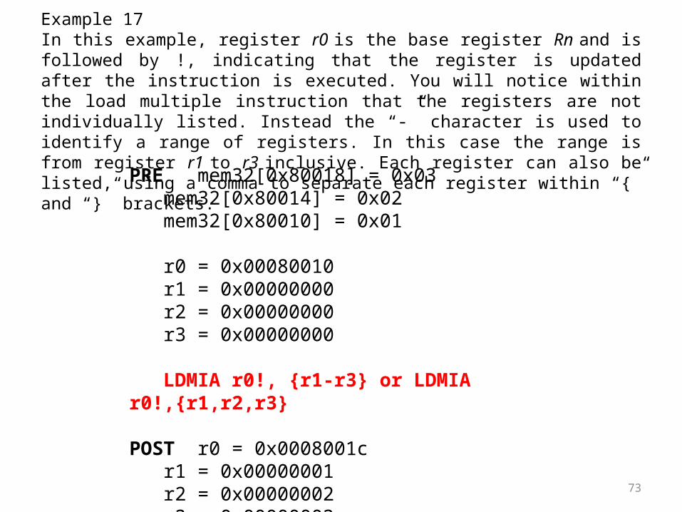
Example 17In this example, register r0 is the base register Rn and is followed by !, indicating that the register is updated after the instruction is executed. You will notice within the load multiple instruction that the registers are not individually listed. Instead the “-” character is used to identify a range of registers. In this case the range is from register r1 to r3 inclusive. Each register can also be listed, using a comma to separate each register within “{” and “}” brackets.
PRE mem32[0x80018] = 0x03mem32[0x80014] = 0x02mem32[0x80010] = 0x01
r0 = 0x00080010r1 = 0x00000000r2 = 0x00000000r3 = 0x00000000
LDMIA r0!, {r1-r3} or LDMIA r0!,{r1,r2,r3}
POST r0 = 0x0008001cr1 = 0x00000001r2 = 0x00000002r3 = 0x00000003

74
• The base register r0 points to memory address 0x80010 in the PRE condition. Memory addresses 0x80010, 0x80014, and 0x80018 contain the values 1, 2, and 3 respectively. After the load multiple instruction executes registers r1, r2, and r3 contain these values. The base register r0 now points to memory address 0x8001c after the last loaded word.
Let us see graphical representation
Pre-condition for LDMIA instruction.

75
Post-condition for LDMIA instruction.
Post-condition for LDMIB instruction.

76
Load-store multiple pairs when base update used.
Above Table shows a list of load-store multiple instruction pairs. If you use a store with base update, then the paired load instruction of the same number of registers will reload the data and restore the base address pointer. This is useful when you need to temporarily save a group of registers and restore them later.

77
Example 18This example shows an STM increment before instruction followed by an LDM decrement after instruction.
PRE (1) r0 = 0x00009000r1 = 0x00000009r2 = 0x00000008r3 = 0x00000007
STMIB r0!, {r1-r3}
MOV r1, #1MOV r2, #2MOV r3, #3
PRE(2) r0 = 0x0000900cr1 = 0x00000001r2 = 0x00000002r3 = 0x00000003
LDMDA r0!, {r1-r3}
POST r0 = 0x00009000r1 = 0x00000009r2 = 0x00000008r3 = 0x00000007
The STMIB instruction stores the values 7, 8, 9 to memory. We then corrupt register r1 to r3.The LDMDA reloads the original values and restores the base pointer r0.

78
Example 19We illustrate the use of the load-store multiple instructions with a block memory copyexample. This example is a simple routine that copies blocks of 32 bytes from a sourceaddress location to a destination address location. The example has two load-store multiple instructions, which use the same increment after addressing mode.
; r9 points to start of source data say 0x00002000; r10 points to start of destination data; r11 points to end of the source
loopLDMIA r9!, {r0-r7}; load 32 bytes from source and update r9 pointerSTMIA r10!, {r0-r7} ; store 32 bytes to destination and update r10 pointer and store them
; have we reached the endCMP r9, r11BNE loop

79
LDMIA r9!, {r0-r7}
0X083
0X045
0X023
0X040
0X00002000
0X003
0X055
0X023
0X040
0X00002004
0X00002008
0X0000200C
0X00002010
0X00002014
0X00002018
0X0000201C
0X008 0X00002020
r0 <- mem32[r9] = 0X040r1 <- mem32[r9] + 4 = 0X023r2 <- mem32[r9] + 8 = 0X055r3 <- mem32[r9] + 12 = 0X003r4 <- mem32[r9] + 16 = 0X040r5 <- mem32[r9] + 20 = 0X023r6 <- mem32[r9] + 24 = 0X045r7 <- mem32[r9] + 28 = 0X083
INCREMENT AFTER FORMULAE
Starting Address = Rn i.e. r9 here(Base register) 0x00002000Ending Address = Rn + 4*N -4
Now as we have r9! So it is auto updated by formulae Rn + 4* N
i.e. r9 = 0x00002020
Source Memory Block
r9

80
STMIA r10!, {r0-r7}
INCREMENT AFTER FORMULAE
Let destination address : 0x00003000Starting Address = Rn i.e. r10 here(Base register) 0x00003000Ending Address = Rn + 4*N -4
r0 -> mem32[r10] = 0X040 @ 0X00003000r1 -> mem32[r10] + 4 = 0X023 @ 0X00003004 r2 -> mem32[r10] + 8 = 0X055 @ 0X00003008r3 -> mem32[r10] + 12 = 0X003 @ 0X0000300Cr4 -> mem32[r10 + 16 = 0X040 @ 0X00003010r5 -> mem32[r10] + 20 = 0X023 @ 0X00003014r6 -> mem32[r10] + 24 = 0X045 @ 0X00003018r7 -> mem32[r10] + 28 = 0X083 @ 0X0000301C
0X083
0X045
0X023
0X040
0X00003000
0X003
0X055
0X023
0X040
0X00003004
0X00003008
0X0000300C
0X00003010
0X00003014
0X00003018
0X0000301C
0X008 0X00003020
Destination Memory Block
Now as we have r9! So it is auto updated by formulae Rn + 4* N
i.e. r10 = 0x00003020
r10

81
• This routine relies on registers r9, r10, and r11 being set up before the code is executed.
• Registers r9 and r11 determine the data to be copied, and register r10 points to the destination in memory for the data.
• LDMIA loads the data pointed to by register r9 into registers r0 to r7. It also updates r9 to point to the next block of data to be copied. STMIA copies the contents of registers r0 to r7 to the destination memory address pointed to by register r10.
• It also updates r10 to point to the next destination location. CMP and BNE compare pointers r9 and r11 to check whether the end of the block copy has been reached. If the block copy is complete, then the routine finishes; otherwise the loop repeats with the updated values of register r9 and r10.
• The BNE is the branch instruction B with a condition mnemonic NE (not equal). If the previous compare instruction sets the condition flags to not equal, the branch instruction is executed.

82Figure : Block memory copy in the memory map

83
Stack Processing• A stack is usually implemented as a linear data structure which grows
up (an ascending stack) or down (a descending stack) memory
• A stack pointer holds the address of the current top of the stack, either by pointing to the last valid data item pushed onto the stack (a full stack), or by pointing to the vacant slot where the next data item will be placed (an empty stack)
• ARM multiple register transfer instructions support all four forms of stacks– Full ascending: grows up; base register points to the highest address
containing a valid item– empty ascending: grows up; base register points to the first empty location
above the stack– Full descending: grows down; base register points to the lowest address
containing a valid data– empty descending: grows down; base register points to the first empty
location below the stack

84
• The ARM architecture uses the load-store multiple instructions to carry out stack operations.
• The pop operation (removing data from a stack) uses a load multiple instruction; similarly, the push operation (placing data onto the stack) uses a store multiple instruction.
• When using a stack you have to decide whether the stack will grow up or down in memory. A stack is either ascending (A) or descending (D). Ascending stacks grow towards higher memory addresses; in contrast, descending stacks grow towards lower memory addresses.
• When you use a full stack (F), the stack pointer sp points to an address that is the last used or full location (i.e., sp points to the last item on the stack). In contrast, if you use an empty stack (E) the sp points to an address that is the first unused or empty location (i.e., it points after the last item on the stack).
• There are a number of load-store multiple addressing mode aliases available to support stack operations (see Table). Next to the pop column is the actual load multiple instruction equivalent.
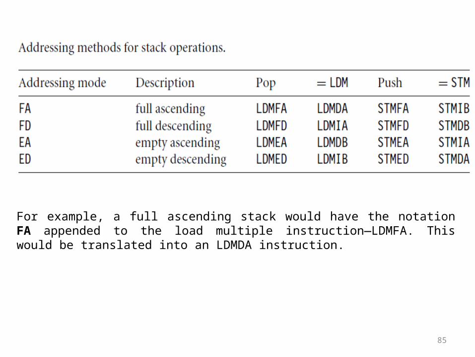
85
For example, a full ascending stack would have the notation FA appended to the load multiple instruction—LDMFA. This would be translated into an LDMDA instruction.

86
Example 20The STMFD instruction pushes registers onto the stack, updating the sp. Figure shows a push onto a full descending stack. You can see that when the stack grows the stack pointer points to the last full entry in the stack.
PRE r1 = 0x00000002r4 = 0x00000003sp = 0x00080014
STMFD sp!, {r1,r4}
POST r1 = 0x00000002r4 = 0x00000003sp = 0x0008000c
NOTE : Stack pointer points to the last full entry in the stack.

87
Example 21In contrast, Next figure shows a push operation on an empty stack using the STMED instruction. The STMED instruction pushes the registers onto the stack but updates register sp to point to the next empty location.
PRE r1 = 0x00000002r4 = 0x00000003sp = 0x00080010
STMED sp!, {r1,r4}
POST r1 = 0x00000002r4 = 0x00000003sp = 0x00080008
NOTE : SP to point to the next empty location.

88
Block Copy Addressing

Stack ExamplesSTMFD sp!,
{r0,r1,r3-r5}
r5r4r3r1r0S
P
Old SP
STMED sp!,{r0,r1,r3-r5}
r5r4r3r1r0
SP
Old SP
r5r4r3r1r0
STMFA sp!,{r0,r1,r3-r5}
SP
Old SP 0x400
0x418
0x3e8
STMEA sp!,{r0,r1,r3-r5}
r5r4r3r1r0
SP
Old SP
90
Load-Store Instructions
• Three basic forms to move data between ARM registers and memory– Single register load and store instruction
• A byte, a 16-bit half word, a 32-bit word
– Multiple register load and store instruction• To save or restore workspace registers for procedure entry and exit• To copy clocks of data
– Single register swap instruction• A value in a register to be exchanged with a value in memory• To implement semaphores to ensure mutual exclusion on accesses

91
• The swap instruction is a special case of a load-store instruction. It swaps the contents of memory with the contents of a register.
• This instruction is an atomic operation—it reads and writes a location in the same bus operation, preventing any other instruction from reading or writing to that location until it completes.
• Swap cannot be interrupted by any other instruction or any other bus access. We say the system “holds the bus” until the transaction is complete.
Single Register Swap Instruction

92
Syntax: SWP{B}{<cond>} Rd,Rm,[Rn]
Rd <- [Rn], [Rn] <- Rm
Rm Rd
Rn
32
1
temp
Memory

93
Example 21The swap instruction loads a word from memory into register r0 and overwrites the memory with register r1.
PRE mem32[0x9000] = 0x12345678r0 = 0x00000000r1 = 0x11112222r2 = 0x00009000
SWP r0, r1, [r2]
POST mem32[0x9000] = 0x11112222r0 = 0x12345678r1 = 0x11112222r2 = 0x00009000
This instruction is particularly useful when implementing semaphores and mutual exclusion in an operating system. You can see from the syntax that this instruction can also have a byte size qualifier B, so this instruction allows for both a word and a byte swap.

94
0X36197488
0X09059945
0X12345678 0X00009000
0X00009004
0X00009008
PRE mem32[0x9000] = 0x12345678r0 = 0x00000000r1 = 0x11112222r2 = 0x00009000
0X54233083 0X00009008
POST mem32[0x9000] = 0x11112222r0 = 0x12345678r1 = 0x11112222r2 = 0x00009000
0X36197488
SWP r0, r1, [r2]
0X09059945
0X11112222 0X00009000
0X00009004
0X00009008
0X54233083 0X00009008
0X00000000r0
0X11112222r1
0X00009000r2
0x12345678r0
0X11112222r1
0X00009000r2
LOAD
STORE

95
Concept of SEMAPHORE
• In computer science, a semaphore is a variable or abstract data type that provides a simple but useful abstraction for controlling access by multiple processes to a common resource in a parallel programming environment.
• A semaphore, in its most basic form, is a protected integer variable that can facilitate and restrict access to shared resources in a multi-processing environment.
• The two most common kinds of semaphores are counting semaphores and binary semaphores. Counting semaphores represent multiple resources, while binary semaphores, as the name implies, represents two possible states (generally 0 or 1; locked or unlocked).

96
• A semaphore can only be accessed using the following operations: wait() and release().
• wait() is called when a process wants access to a resource. This would be equivalent to the arriving customer trying to get an open table. If there is an open table, or the semaphore is greater than zero, then he can take that resource and sit at the table. If there is no open table and the semaphore is zero, that process must wait until it becomes available. signal() is called when a process is done using a resource, or when the patron is finished with his meal.
• The following is an implementation of this counting semaphore (where the value can be greater than 1):

97
• In this implementation, a process wanting to enter its critical section it has to acquire the binary semaphore which will then give it mutual exclusion until it signals that it is done.
• For example, we have semaphore s, and two processes, P1 and P2 that want to enter their critical sections at the same time. P1 first calls wait(s). The value of s is decremented to 0 and P1 enters its critical section. While P1 is in its critical section, P2 calls wait(s), but because the value of s is zero, it must wait until P1 finishes its critical section and executes signal(s).
• When P1 calls signal, the value of s is incremented to 1, and P2 can then proceed to execute in its critical section (after decrementing the semaphore again). Mutual exclusion is achieved because only one process can be in its critical section at any time.

98
Example 22This example shows a simple data guard that can be used to protect data from being written by another task. The SWP instruction “holds the bus” until the transaction is complete.
loopMOV r1, =semaphoreMOV r2, #1SWP r3, r2, [r1] ; hold the bus until completeCMP r3, #1BEQ loop
The address pointed to by the semaphore either contains the value 0 or 1. When the semaphore equals 1, then the service in question is being used by another process. Theroutine will continue to loop around until the service is released by the other process—in other words, when the semaphore address location contains the value 0.

99
ARM instructions by instruction class
1. Data Processing Instructions
2. Branch Instructions
3. Load-Store Instructions
4. Software Interrupt Instruction
5. Program Status Register Instructions

100
Software Interrupt Instruction
• The software interrupt instruction is used for calls to the operating system and is often called a 'supervisor call'.
• It puts the processor into supervisor mode and begins executing instructions from address 0x08.
Binary encoding
Introduction
COND OPCODE 24-BIT (INTERPRETED) IMMEDIATE
31 28 27 24 23 0

101
The 24-bit immediate field does not influence the operation of the instruction but may be interpreted by the system code. If the condition is passed the instruction enters supervisor mode using the standard ARM exception entry sequence. In detail, the processor actions are:1. Save the address of the instruction after the SWI in r14_svc.2. Save the CPSR in SPSR_svc. 3. Enter supervisor mode and disable IRQs (but not FIQs) by setting CPSR[4:0]
to 100112 and CPSR[7] tol.4. Set the PC to and begin executing the instructions there.
Binary encoding
COND OPCODE 24-BIT (INTERPRETED) IMMEDIATE
31 28 27 24 23 0
Description
To return to the instruction after the SWI the system routine must not only copy r14_svc back into the PC, but it must also restore the CPSR from SPSR_svc.

102
Syntax: SWI{<cond>} SWI_number

103
Example 23Here we have a simple example of an SWI call with SWI number 0x123456, used by ARM toolkits as a debugging SWI. Typically the SWI instruction is executed in user mode.
PRE cpsr = nzcVqift_USERpc = 0x00008000lr = 0x003fffff; lr = r14r0 = 0x12
0x00008000 SWI 0x123456
POST cpsr = nzcVqIft_SVCspsr = nzcVqift_USERpc = 0x00000008lr = 0x00008004r0 = 0x12
Since SWI instructions are used to call operating system routines, you need some form of parameter passing. This is achieved using registers. In this example, register r0 is used to pass the parameter 0x12. The return values are also passed back via registers.
Code called the SWI handler is required to process the SWI call. The handler obtains the SWI number using the address of the executed instruction, which is calculated from the link register lr.

104
ARM instructions by instruction class
1. Data Processing Instructions
2. Branch Instructions
3. Load-Store Instructions
4. Software Interrupt Instruction
5. Program Status Register Instructions(MSR, MRS) (Self Study!!!) Refer Steve Furber

Byte organizations • Little-endian mode:- with the lowest-order byte residing in the low-
order bits of the word
• Big-endian mode: - the lowest-order byte stored in the highest bits
of the word

Byte organizations

107
Thumb Mode
• Thumb is a 16-bit instruction set– Optimized for code density from C code– Improved performance form narrow memory– Subset of the functionality of the ARM instruction set
• Core has two execution states – ARM and Thumb– Switch between them using BX instruction
• Thumb has characteristic features:– Most Thumb instruction are executed unconditionally– Many Thumb data process instruction use a 2-address format– Thumb instruction formats are less regular than ARM
instruction formats, as a result of the dense encoding.

108
Thumb has higher code density !
• Code density: it is define as the space taken up in memory by an executable program.
• On average, a Thumb implementation of the same code takes up around 30% less memory than the equivalent ARM implementation.
• Figure 4.1 shows the same divide code routine implemented in ARM and Thumb assembly code. Even though the Thumb implementation uses more instructions, the overall memory footprint is reduced. Code density was the main driving force for the Thumb instruction set.

109
Thumb implementation uses more instructions, the overall memory footprint is reduced.
Code density was the main driving force for the Thumb instruction set. Because it was also designed as a compiler target, rather than for hand-written assembly code, we recommend that you write Thumb-targeted code in a high-level language like C or C++.
110
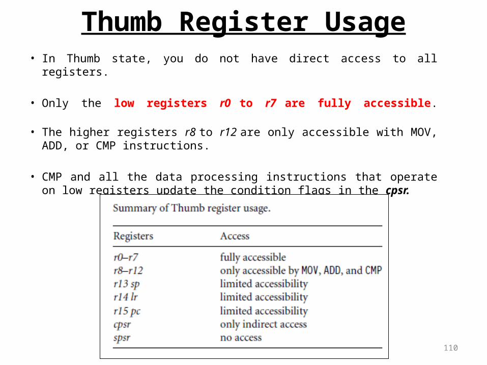
Thumb Register Usage• In Thumb state, you do not have direct access to all registers.
• Only the low registers r0 to r7 are fully accessible.
• The higher registers r8 to r12 are only accessible with MOV, ADD, or CMP instructions.
• CMP and all the data processing instructions that operate on low registers update the condition flags in the cpsr.

111
Thumb Instruction Set (1/3)

112
Thumb Instruction Set (2/3)

113
Thumb Instruction Set (3/3)

114
Thumb Instruction Entry and Exit
T bit, bit 5 of CPSR If T = 1, the processor interprets the instruction stream as 16-bit Thumb
instruction If T = 0, the processor interprets if as standard ARM instructions
Thumb Entry ARM cores startup, after reset, execution ARM instructions Executing a branch and Exchange instruction (BX)
Set the T bit if the bottom bit of the specified register was set Switch the PC to the address given in the remainder of the register
Thumb Exit Executing a thumb BX instruction

115
ARM-Thumb Interworking• ARM-Thumb interworking is the name given to the method of linking
ARM and Thumb code together for both assembly and C/C++.
• To call a Thumb routine from an ARM routine, the core has to change state. This state change is shown in the T bit of the cpsr.
• The BX and BLX branch instructions cause a switch between ARM and Thumb state while branching to a routine.
• The BX lr instruction returns from a routine, also with a state switch if necessary.

116
• There are two versions of the BX or BLX instructions: an ARM instruction and a Thumb equivalent.
• The ARM BX instruction enters Thumb state only if bit 0 of the address in Rn is set to binary 1; otherwise it enters ARM state. The Thumb BX instruction does the same.
Syntax: BX RnBLX Rn | label

117
Interworking Instructions
• Interworking is achieved using the Branch Exchange instructions– In Thumb state
BX Rn– In ARM state (on Thumb-aware cores only)
BX<condition> RnWhere Rn can be any registers (R0 to R15)
• The performs a branch to an absolute address in 4GB address space by copying Rn to the program counter
• Bit 0 of Rn specifies the state to change to
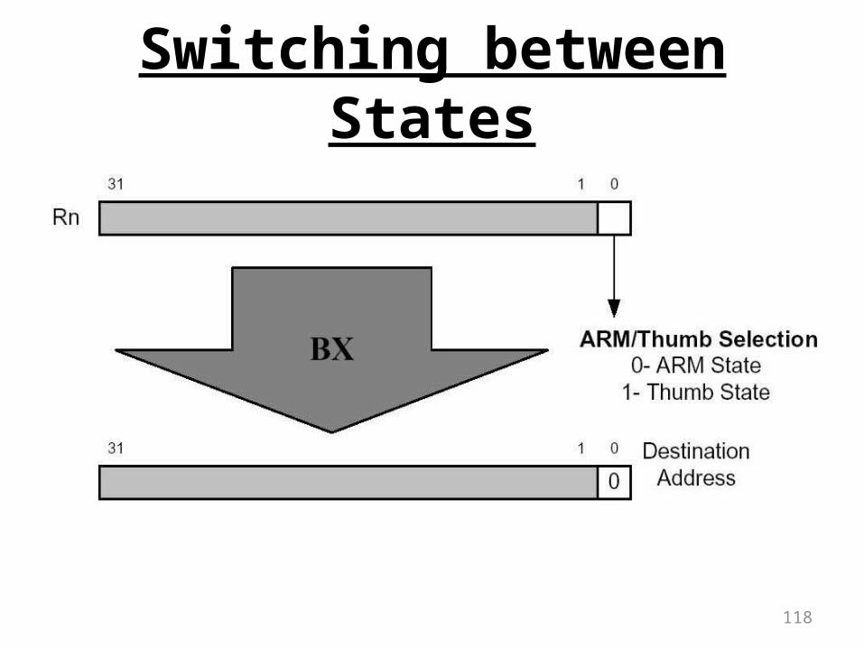
118
Switching between States

119
Example 24
;Start off in ARM stateCODE32ADR r0,Into_Thumb+1 ;generate branch target
;address & set bit 0;hence arrive Thumb
stateBX r0 ;branch exchange to Thumb…CODE16 ;assemble subsequent as Thumb
Into_Thumb …ADR r5,Back_to_ARM ;generate branch target to
;word-aligned address,;hence bit 0 is
cleared.BX r5 ;branch exchange to ARM…CODE32 ;assemble subsequent as ARM
Back_to_ARM …

120
Summary

ARM data instructions
• MLA r0,rl,r2,r3 ,r0=r1 x r2 + r3
ADD ADC SUB SBC RSB RSC MUL MLA
AddAdd with carrySubtractSubtract with carryReverse subtract ,RSB r0,r1,r2, r0=r2 – r1Reverse subtract with carryMultiplyMultiply and accumulate

ARM data instructions
• BIC r0,r1,r2 sets r0 to r1 and not r2 - uses the second source operand as a mask, a bit in
mask is 1, the corresponding bit in first source operand is cleared
ANDORREORBIC
Bit-wise andBit-wise orBit-wise exclusive-orBit clear

ARM data instructionsLSL LSR ASL ASR ROR RRX
Logical shift left (zero fill) Logical shift right (zero fill) Arithmetic shift left Arithmetic shift right, copies the sign bit Rotate right Rotate right extended with C, performs a 33-bit rotate

ARM comparison instructions
• only set the values of the NZCV bits
CMPCMN
TSTTEQ
CompareNegated compare, uses an addition to set the status bits Bit-wise test, a bit-wise AND Bit-wise negated test, an exclusive-or
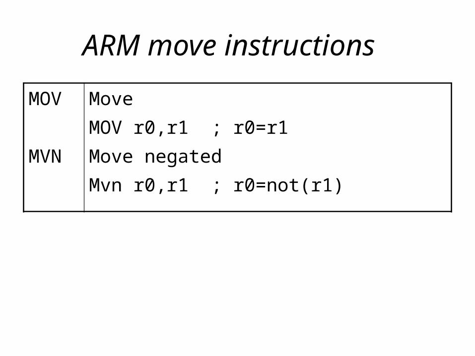
ARM move instructions
MOV MVN
MoveMOV r0,r1 ; r0=r1Move negated Mvn r0,r1 ; r0=not(r1)

ARM load-store instructions
LDRSTRLDRHSTRHLDRSHLDRBSTRBADR
LoadStoreLoad half-wordStore half-wordLoad half-word signedLoad byteStore byteSet register to address

C Assignments in ARM Instructions
• x = (a + b) - c;• using r0 for a, r1 for b, r2 for c, and r3 for x. • registers for indirect addressing. Indirect r4• load values of a, b, and c into registers • store value of x back to memory

C Assignments in ARM Instructions x = (a + b) - c;
ADR r4,a ; get address for aLDR r0,[r4] ; get value of aADR r4,b ; get address for b, using r4LDR r1,[r4] ; load value of bADD r3,r0,r1 ; set result for x to a + bADR r4,c ; get address for cLDR r2,[r4] ; get value of cSUB r3,r3,r2 ; complete computation of xADR r4,x ; get address for xSTR r3,[r4] ; store x at proper location

C Assignments in ARM Instructions
• y = a*(b + c);• using r0 for both a and b, r1 for c, and r2 for y• use r4 to store addresses for indirect
addressing

C Assignments in ARM Instructions y = a*(b + c);
ADR r4,b ; get address for bLDR r0,[r4] ;get value of bADR r4,c ; get address for cLDR r1,[r4] ; get value of cADD r2,r0,r1 ; compute partial result of y=b+cADR r4,a ; get address for aLDR r0,[r4] ; get value of aMUL r2,r2,r0 ; compute final value of y=a*(b+c)ADR r4,y ; get address for ySTR r2,[r4] ; store value of y at proper location

C Assignments in ARM Instructions
• z = (a « 2) | (b & 15);• using r0 for a and z, r1 for b, • r4 for addresses

C Assignments in ARM Instructions z = (a « 2) | (b & 15);
ADR r4,a ; get address for aLDR r0,[r4] ; get value of aMOV r0,r0,LSL 2 ; perform shift (a « 2)ADR r4,b ; get address for bLDR r1,[r4] ; get value of bAND r1,r1,#15 ; perform logical AND (b & 15)ORR r1,r0,r1 ; compute final value of zADR r4,z ; get address for zSTR r1,[r4] ; store value of z


![ARM 沈剑桥 张本. 11/20/2015 4:38 PM Websoft, Nanjing Univ. [ ] 2 What is ARM? Advanced RISC Machines (Acorn RISC Machine )](https://img.pdfslide.net/doc/110x75/56649f325503460f94c4e56d/arm-11202015-438-pm-websoft-nanjing-univ-httpwsnjueducn.jpg)