Embed Size (px)
Citation preview
© S
täub
li Fa
verg
es 2
005
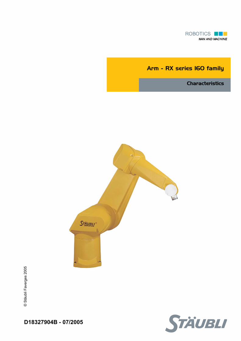
Arm - RX series 160 family
Characteristics
D18327904B - 07/2005
2 D18327904B - 07/2005
The specifications contained in the present document can be modified without notice. Althoughall necessary precautions have been taken to ensure that the information contained in thisdocument is correct, STÄUBLI cannot be held responsible for any errors or omissions found inthe illustrations, drawings and specifications contained in the said document.
D18327904B - 07/2005 3
TABLE OF CONTENTS
1 - DESCRIPTION....................................................................................... 7
1.1. GENERAL DESCRIPTION ....................................................................................................... 9
1.2. DESIGNATION OF ROBOTS OF THE RX SERIES 160 FAMILY ......................................... 11
1.3. GENERAL CHARACTERISTICS............................................................................................ 131.3.1. Overall dimensions ...................................................................................................... 131.3.2. Work environment ....................................................................................................... 131.3.3. Weight ......................................................................................................................... 13
1.4. PERFORMANCE .................................................................................................................... 151.4.1. Torque limits ................................................................................................................ 151.4.2. Amplitude, speed and resolution ................................................................................. 171.4.3. Modification of amplitudes ........................................................................................... 17
1.5. LOAD CAPACITY – MECHANICAL INTERFACE ................................................................. 191.5.1. Load capacity .............................................................................................................. 211.5.2. Attachment of additional load on forearm.................................................................... 231.5.3. Additional load diagrams ............................................................................................. 25
1.6. LOGIN USER .......................................................................................................................... 27
1.7. RELEASING JOINT BRAKE .................................................................................................. 27
1.8. PNEUMATIC AND ELECTRIC CIRCUITS (EXCEPT FOR CLEAN ROOM APPLICATION) ... 291.8.1. Pneumatic circuit ......................................................................................................... 291.8.2. Electric circuit .............................................................................................................. 31
1.9. PNEUMATIC AND ELECTRIC CIRCUITS CLEAN ROOM APPLICATION.............................. 331.9.1. Pneumatic circuit ......................................................................................................... 331.9.2. Electric circuit .............................................................................................................. 35
1.10. PRESSURIZATION UNIT FOR DUSTY ENVIRONMENTS.................................................... 371.10.1. Purpose ....................................................................................................................... 371.10.2. Installation ................................................................................................................... 37
1.11. SAFETY .................................................................................................................................. 39
2 - ON-SITE PREPARATION.................................................................... 41
2.1. WORKING SPACE ................................................................................................................. 43
2.2. ATTACHMENT........................................................................................................................ 43

4 D18327904B - 07/2005
D18327904B - 07/2005 5
3 - INSTALLATION ................................................................................... 45
3.1. ARM PACKAGING ................................................................................................................. 47
3.2. HANDLING OF PACKING ...................................................................................................... 47
3.3. UNPACKING AND INSTALLATION OF ARM ....................................................................... 49
3.4. INSTALLATION OF ARM ....................................................................................................... 513.4.1. Installation of arm on floor ........................................................................................... 513.4.2. Installation of arm on ceiling ........................................................................................ 513.4.3. Mounting floor quality .................................................................................................. 51
3.5. SPRING TENSION.................................................................................................................. 53

6 D18327904B - 07/2005

Chapter 1 – Description
D18327904B - 07/2005 7
CHAPTER 1 –
DESCRIPTION
8 D18327904B - 07/2005
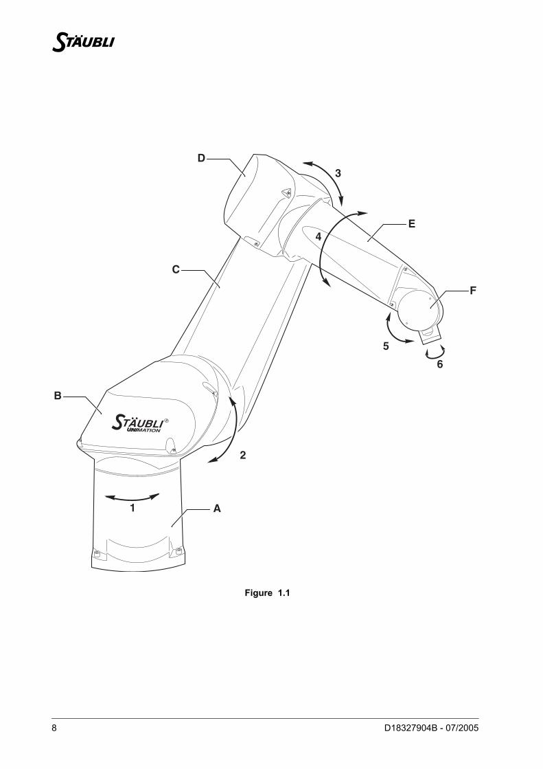
Figure 1.1
R
1
3
A
B
C
D
E
F
2
6
5
4
Chapter 1 – Description
D18327904B - 07/2005 9
1.1. GENERAL DESCRIPTION
The arm consists of segments or members interconnected by joints (figure 1.1).
Each joint comprises an axis around which two members pivot.
The movements of the robot’s joints are generated by brushless motors coupled to resolvers. Each of thesemotors is equipped with a parking break.
This reliable and robust assembly associated with an innovative counting system allows the absoluteposition of the robot to be known at all times.
The arm assembly is sufficiently flexible and is able to perform a great variety of applications.
Example: Handling of loads, assembly, process, application of adhesive beads, control/check and cleanroom applications. This list is not restrictive: for further information, please consult us.
The various elements of the robot’s arm are: the base (A), the shoulder (B), the arm (C), the elbow (D), theforearm (E) and the wrist (F) (figure 1.1).
The robot arm assembly thus contains the motorization, brakes, motion transmission mechanisms, cablebundles, pneumatic and electric circuits for the user and the counterbalance system.
Of simple construction, the RX160 arm assembly consists of a rigid and encased structure (protection IP65to standard NF EN 60529) to protect it against external aggressions. Its design is based on transmissionmodules: JCS (STÄUBLI Combined Joint) used on axis 1, 2, 3 and 4 (figure 1.1).
The wrist consists of axis 5 and 6.
Arm balance is performed by an integrated spring system. The arm has a built-in spring counterbalancesystem giving an attractive low weight system.
10 D18327904B - 07/2005
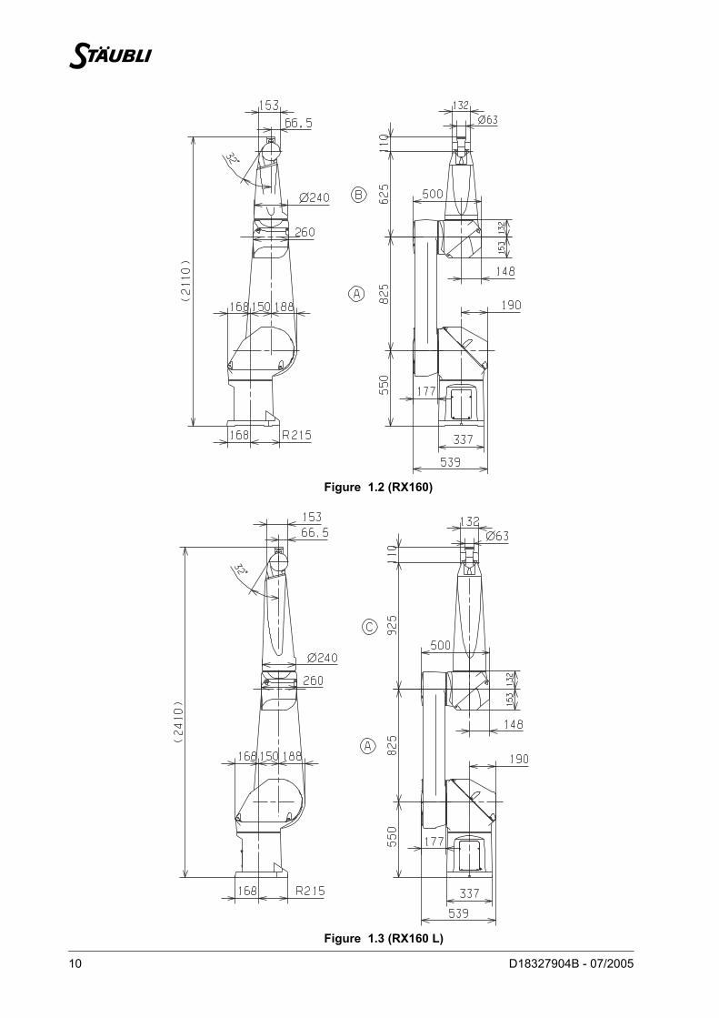
Figure 1.2 (RX160)
Figure 1.3 (RX160 L)
Chapter 1 – Description
D18327904B - 07/2005 11
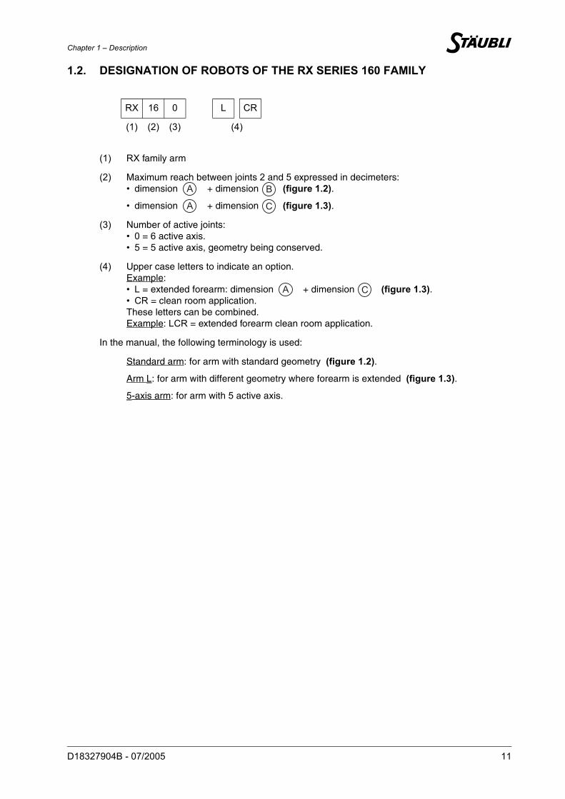
1.2. DESIGNATION OF ROBOTS OF THE RX SERIES 160 FAMILY
RX 16 0 L CR
(1) (2) (3) (4)
(1) RX family arm
(2) Maximum reach between joints 2 and 5 expressed in decimeters:• dimension + dimension (figure 1.2).
• dimension + dimension (figure 1.3).
(3) Number of active joints:• 0 = 6 active axis.• 5 = 5 active axis, geometry being conserved.
(4) Upper case letters to indicate an option.Example:• L = extended forearm: dimension + dimension (figure 1.3).• CR = clean room application.These letters can be combined.Example: LCR = extended forearm clean room application.
In the manual, the following terminology is used:
Standard arm: for arm with standard geometry (figure 1.2).
Arm L: for arm with different geometry where forearm is extended (figure 1.3).
5-axis arm: for arm with 5 active axis.
A B
A C
A C

12 D18327904B - 07/2005
Chapter 1 – Description
D18327904B - 07/2005 13
1.3. GENERAL CHARACTERISTICS
1.3.1. OVERALL DIMENSIONS (figures 1.2 and 1.3)
1.3.2. WORK ENVIRONMENT
• Working temperature: + 5°C to + 40°C (according to standard(s) and/or directive(s): NF EN 60 204-1)
• Humidity: 30% to 95% max. non-condensing (according to standard(s) and/or directive(s):NF EN 60 204-1)
• Altitude: 2000 m max
• Vibrations: please consult us
Clean room application: Cleanliness class ISO 4 according to standard ISO 14644-1
1.3.3. WEIGHT
CAUTION: It may be necessary to perform a warm-up cycle before nominal performances areobtained.
STANDARD ARM ARM L
248 kg 250 kg
14 D18327904B - 07/2005
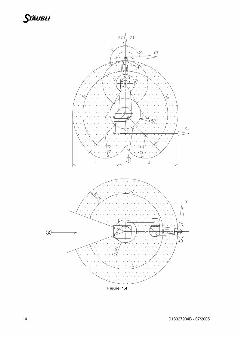
Figure 1.4
2
Chapter 1 – Description
D18327904B - 07/2005 15
1.4. PERFORMANCE
Figure 1.4
1.4.1. TORQUE LIMITS
(1) if axis6 torque = 0(2) for maximum torque on axis 6
Brake release access area
Area accessible in righty configuration
STANDARD ARM ARM LWork envelopeR.M max. reach between axis 1 and 5 1600 mm 1900 mmR.m1 min. reach between axis 1 and 5 422 mm 463 mmR.m2 min. reach between axis 2 and 5 312 mm 462 mmR.b reach between axis 3 and 5 625 mm 925 mmH 1300 mm 1600 mmJ 1600 mm 1900 mmMaximum speed at load center of gravity 18.9 m/sRepeatability at constant temperature ± 0.05 mm
REFERENCE AXIS
AXIS 5 (Z6) AXIS 6 (Z7)Static torque (Nm) 89 (1) 66 (2) 30Peak torque (Nm) 269 (1) 210(2) 91
1
2

16 D18327904B - 07/2005
Chapter 1 – Description
D18327904B - 07/2005 17
1.4.2. AMPLITUDE, SPEED AND RESOLUTION
Low speed in manual mode: 250 mm/s at tool centre point and 45 °/s on each joint.
Maximum Cartesian speed: 2.5 m/s.
1.4.3. MODIFICATION OF AMPLITUDESThe arm is installed to obtain maximum angular amplitudes.
The amplitude of the joints can be voluntarily limited by the "software" (see chapter on programming). Also,the position of the mechanical travel limiters on axis 1, 2 and 3 and of the electrical travel limiters on joints1 and 2 can be modified in a certain number of positions (for modification, please consult STÄUBLI).
Axis 1 2 3 4 5 6 (1) Can be configured by software up to ± 18 000°. See the "Software configuration" chapter in the "Controller" documentation.
(2) Maximum speed for reduced conditions of load and inertia.
Amplitude (°) 320 275 300 540 225 540 (1)
Working range distribution (°)
A ± 160 B ± 137.5 C ± 150 D ± 270 E+120 ; -105
F ± 270
Nominal speed (°/s) 165 150 190 295 260 440Maximum speed (°/s) (2)
278 278 356 409 800 1125
Angular resolution (°.10-3)
0.68 0.68 0.87 1.0 1.95 2.75
CAUTION: In some arm configurations, the maximum joint speeds can be reached only if payloadsand inertias are reduced.
18 D18327904B - 07/2005
Figure 1.5
Chapter 1 – Description
D18327904B - 07/2005 19
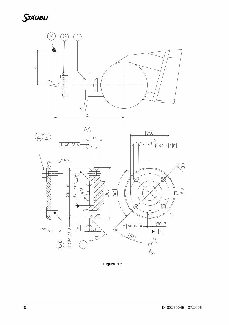
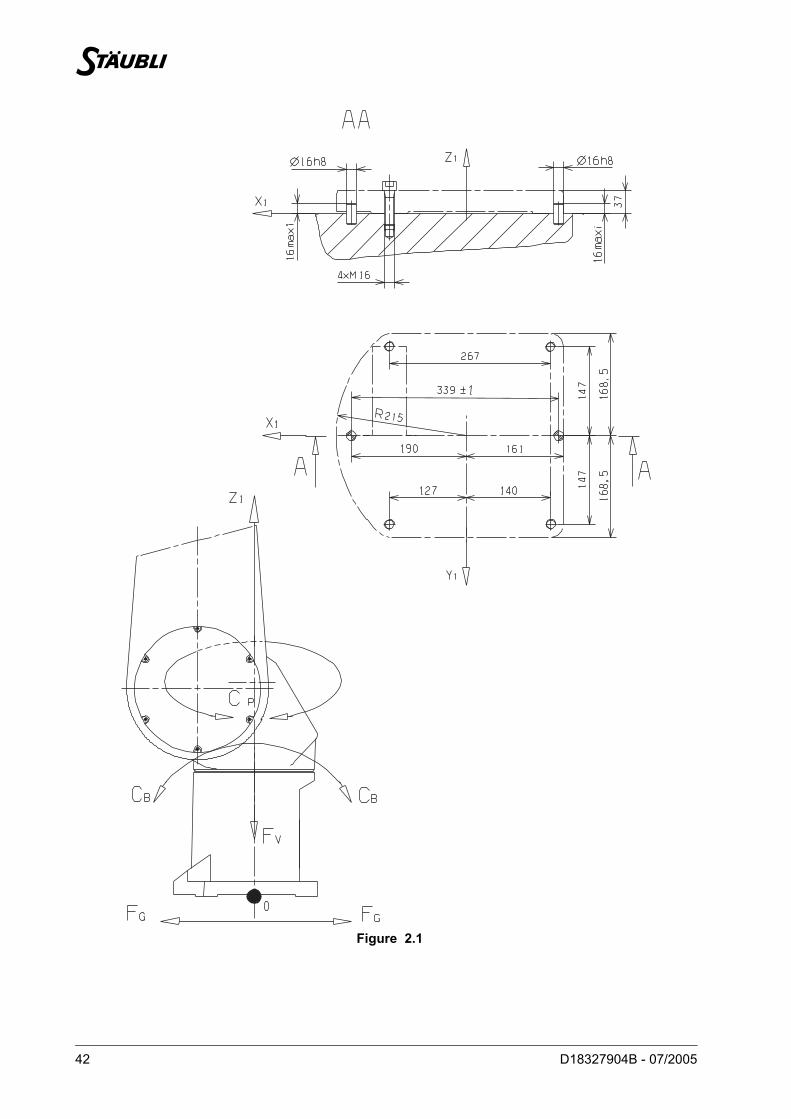
1.5. LOAD CAPACITY – MECHANICAL INTERFACE
Mechanical interface
End-effector
The end-effector is not supplied with the robot arm assembly; its design depends on the robot’s specificapplications. All studies can be undertaken in cooperation with STÄUBLI to obtain optimum performancewithout exceeding the robot arm assembly load limits.
The end-effector is installed on the mechanical interface of the wrist dimensions of which are given onfigure 1.5.
Attachment by 4 M6 screws frame , Class 12-9, torque 16.7 Nm ± 1.2 Nm.
Indexing by pin frame , diameter 6.
Mechanical interface designation:ISO 9409 - 1 - A50 as per Standard ISO 9409 - 1 : 1996 (F) (Standard and L arms)(except the localization of the 4 M6 threaded holes)
CAUTION: Length of end-effector attaching screws is limited to avoid all interference with the wrist(figure 1.5).
1
2
B4
B3

20 D18327904B - 07/2005
Chapter 1 – Description
D18327904B - 07/2005 21
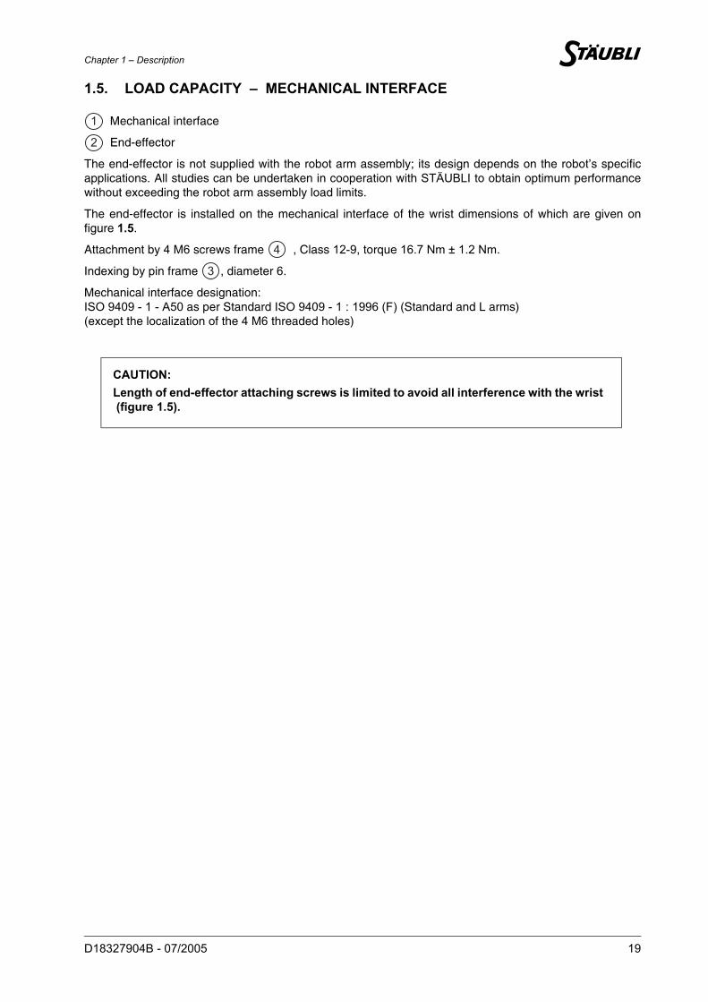
1.5.1. LOAD CAPACITY Figure 1.5
Load characteristics:
Load center of gravity position : z = 200 mm from centerline of joint 5 and x = 100 mm from centerlineof joint 6.
(1) in all configurations and taking maximum inertias into account. See table below.
Figure 1.6
(2) under reduced speed and acceleration conditions:
For CS8C: VEL = 60%, ACC = 30%, DEC = 30%
Load capacity Standard arm Arm L
At nominal speed (1) 20 kg 14 kg
At reduced speed (1) 30 kg 20 kg
Maximum load capacity (see figure 1.6) 34 kg 28 kg
NOMINAL INERTIAS (kg.m²) MAXIMAL INERTIAS (kg.m²) (2)
STANDARD ARM ARM L STANDARD ARM ARM L
For joint 5 0.8 0.56 4 2.8
For joint 6 0.2 0.14 1 0.7
CAUTION: The nominal values can be exceeded to a certain extent but imply a limitation to thespeed and the acceleration of the arm. If these limits are to be exceeded, please consultSTÄUBLI.
BM
22 D18327904B - 07/2005
Figure 1.7
Effective tapped depth
Chapter 1 – Description
D18327904B - 07/2005 23
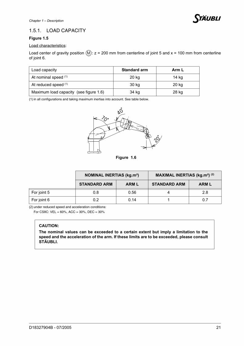
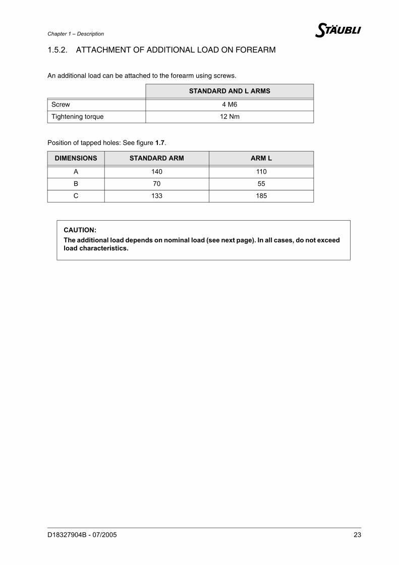
1.5.2. ATTACHMENT OF ADDITIONAL LOAD ON FOREARM
An additional load can be attached to the forearm using screws.
Position of tapped holes: See figure 1.7.
STANDARD AND L ARMS
Screw 4 M6
Tightening torque 12 Nm
DIMENSIONS STANDARD ARM ARM L
A 140 110
B 70 55
C 133 185
CAUTION: The additional load depends on nominal load (see next page). In all cases, do not exceedload characteristics.
24 D18327904B - 07/2005
Figure 1.8 Figure 1.9
Figure 1.10 Figure 1.11
Chapter 1 – Description
D18327904B - 07/2005 25
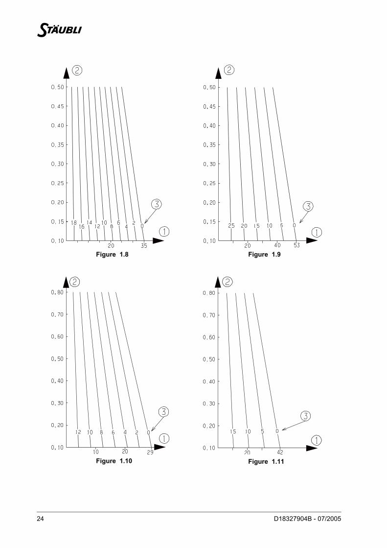
1.5.3. ADDITIONAL LOAD DIAGRAMS
These diagrams can be used to determine the additional load which can be attached to the forearmdepending on its center of gravity position from joint 3 and the load attached to the mechanical interface ofthe wrist.
(1) Reduced speeds:
For CS8C: VEL = 60%, ACC = 30%, DEC = 30%
Additional load (kg)
Additional load center of gravity position (m) from centerline of joint 3.The additional load center of gravity position is at 0.20 m max. from the centerline of joint 4.
Load attached to the mechanical interface of the wrist.200 mm from centerline of joint 5 and 100 mm from centerline of joint 6.
Figure 1.8: for standard RX160Figure 1.9: for standard RX160 with reduced speeds (1)
Figure 1.10: for RX160 with L armFigure 1.11: for RX160 with an L arm at reduced speeds (1)
BM1
BM2
B3
26 D18327904B - 07/2005
Figure 1.12 (RX160)
Figure 1.13 (RX160 CR)
EV1
EV2
R
P2
B2
E10
A2
A1
B1
2
3
P1
P2
J1202
1
4
R
EV2
EV1
P2
B2
E10
A2
A1
B1
2
3
P1
P2
J1202
14
Chapter 1 – Description
D18327904B - 07/2005 27
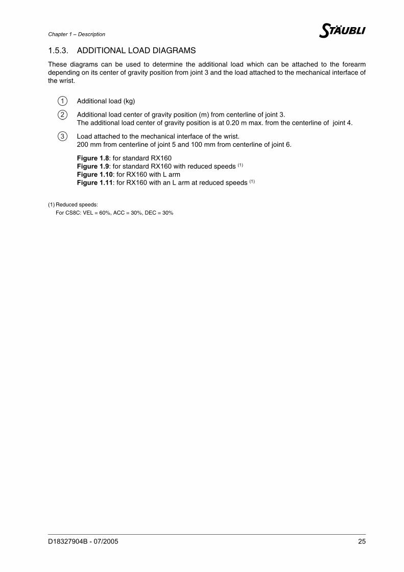
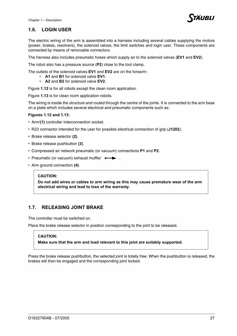
1.6. LOGIN USER
The electric wiring of the arm is assembled into a harness including several cables supplying the motors(power, brakes, resolvers), the solenoid valves, the limit switches and login user. These components areconnected by means of removable connectors.
The harness also includes pneumatic hoses which supply air to the solenoid valves (EV1 and EV2).
The robot also has a pressure source (P2) close to the tool clamp.
The outlets of the solenoid valves EV1 and EV2 are on the forearm:• A1 and B1 for solenoid valve EV1.• A2 and B2 for solenoid valve EV2.
Figure 1.12 is for all robots except the clean room application.
Figure 1.13 is for clean room application robots.
The wiring is inside the structure and routed through the centre of the joints. It is connected to the arm baseon a plate which includes several electrical and pneumatic components such as:
Figures 1.12 and 1.13:
• Arm/(1) controller interconnection socket.
• R23 connector intended for the user for possible electrical connection of grip (J1202).
• Brake release selector (2).
• Brake release pushbutton (3).
• Compressed air network pneumatic (or vacuum) connections P1 and P2.
• Pneumatic (or vacuum) exhaust muffler .
• Arm ground connection (4).
1.7. RELEASING JOINT BRAKE
The controller must be switched on.
Place the brake release selector in position corresponding to the joint to be released.
Press the brake release pushbutton, the selected joint is totally free. When the pushbutton is released, thebrakes will then be engaged and the corresponding joint locked.
CAUTION: Do not add wires or cables to arm wiring as this may cause premature wear of the armelectrical wiring and lead to loss of the warranty.
CAUTION: Make sure that the arm and load relevant to this joint are suitably supported.
28 D18327904B - 07/2005
Figure 1.14
shielded
Chapter 1 – Description
D18327904B - 07/2005 29
1.8. PNEUMATIC AND ELECTRIC CIRCUITS(EXCEPT FOR CLEAN ROOM APPLICATION)
1.8.1. PNEUMATIC CIRCUIT
Plate attached to base
Forearm
Solenoid valves (EV1 and EV2):
• 5/2-way monostable
• Electrically controlled (24 VDC)
• Working pressure: 1.5 to 7 bar.
• Flow coefficient Kv = 8.6.
• Clip-on connector.
• Overvoltage protective circuit and indicator diode.
Description (figure 1.14):
• The arm is connected to the compressed air network (7 bars max., lubricated or not) via the base P1.
• There is a direct line between the base and the forearm (P2).
• The centralized solenoid valve exhaust is directed to the base and through a muffler .
CAUTION: The air must be filtered by a 10 µm filter.
1
12

30 D18327904B - 07/2005
Chapter 1 – Description
D18327904B - 07/2005 31
1.8.2. ELECTRIC CIRCUIT
Figure 1.14
The electrical circuit consists of:
• A male 19-contact socket at the bottom of the arm.
• A female 19-contact socket on the forearm.
These 19 contacts include 3 power contacts and 16 command contacts.
• The 3 power contacts in each socket are connected by a 3-wire conductor with cross-section AWG18(contacts 6-12-19).
• The 16 command contacts in each socket are connected in the following way:
• 2 shielded twisted pairs, cross-section AWG24 connecting contacts 3-9-10 and 1-2-18 in eachsocket.
• 5 twisted pairs, cross-section AWG24 for the other contacts.
Supply voltage: 60 VDC - 25 VAC.
Permissible current:
• 3-wire conductor AWG18: 4.5 A per contact.
• Pairs and shielded pairs AWG24: 2 A per contact.
• Connection to forearm (E10) by R23 elbow male cylindrical connector.
• Connection to base (J1202) by R23 straight female cylindrical connector.
CAUTION: Do not use the shields as a conductive cable.
32 D18327904B - 07/2005
Figure 1.15
shielded
VACUUM
VACUUM
Chapter 1 – Description
D18327904B - 07/2005 33
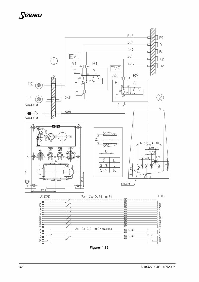
1.9. PNEUMATIC AND ELECTRIC CIRCUITS CLEAN ROOM APPLICATION
1.9.1. PNEUMATIC CIRCUIT
Plate attached to base
Forearm
Solenoid valves (EV1 and EV2):
• 5/2-way monostable.
• Electrically controlled (24 VDC).
• Max. working pressure: vacuum only.
• Flow coefficient Kv = 5.72.
• Clip-on connector.
Description (figure 1.15):
• The arm is connected to the vacuum network via the base (P1 and ).
• There is a direct line between the base and the forearm (P2).
• Max. working pressure: vacuum only.
• There is no exhaust to the outside of the arm for the solenoid valves controlling the vacuum circuit.
CAUTION: Cleanliness of sucked in air must be equivalent to 5 µm filtered air.
1
12

34 D18327904B - 07/2005

Chapter 1 – Description
D18327904B - 07/2005 35
1.9.2. ELECTRIC CIRCUIT
Figure 1.15
The electrical circuit consists of:
• A male 19-contact socket at the bottom of the arm.
• A female 19-contact socket on the forearm.
These 19 contacts include 3 power contacts and 16 command contacts.
• The 3 power contacts in each socket are connected by a 3-wire conductor with cross-section AWG18(contacts 6-12-19).
• The 16 command contacts in each socket are connected in the following way:
• 2 shielded twisted pairs, cross-section AWG24 connecting contacts 3-9-10 and 1-2-18 in eachsocket.
• 5 twisted pairs, cross-section AWG24 for the other contacts.
Supply voltage: 60 VDC - 25 VAC.
Permissible current:
• 3-wire conductor AWG18: 4.5 A per contact.
• Pairs and shielded pairs AWG24: 2 A per contact.
• Connection to forearm (E10) by R23 elbow male cylindrical connector.
• Connection to base (J1202) by R23 straight female cylindrical connector.
CAUTION: Do not use the shields as a conductive cable.
36 D18327904B - 07/2005
Figure 1.16
Figure 1.17
11
1
Chapter 1 – Description
D18327904B - 07/2005 37
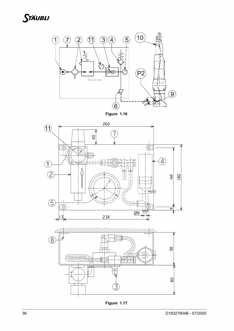
1.10. PRESSURIZATION UNIT FOR DUSTY ENVIRONMENTS
1.10.1. PURPOSE
For very severe applications in dusty environment, to maintain the inside of the arm at a pressure greaterthan the atmospheric pressure to avoid migration of dust.
1.10.2. INSTALLATION
• If the hose (P2) between (9) and (10) is not used, cut the pipe (P2) at (9) and plug (P2) at (10).• If (P2) is used for another function, add a pressure sealed union to the connector mount (black plate at
base of arm to which the electrical connector is attached).• Attach the unit with 4 screws (Ø 6 max.) at item (8) (screws not supplied) to a rigid vertical wall in direction
shown by arrow; the air inlet (1) being to the left of the regulator (2).• Provide for air inlet at (1), this is a G1/4 tapped hole; the air pressure is 10 bar maximum. Before the
pressure arrives at (1), make sure that the regulator (2) is completely screwed out and that the valve (3)is completely screwed in. Before pressurizing the arm, also make sure that the arm is correctly connectedand correctly sealed (covers closed, plugs in hoisting ring tapped hole, pipe connected at (6) and at (9),etc.).
• Install a pipe with an outside Ø 8 between the unit (output 6) and the arm (input P2). Provide a male G1/4union for the pipe with an outside Ø 8. At (P2), the hole is a G1/4 tapped hole for the complete RX range.
• Pressurize the arm.
1) Slowly screw in the regulator. First adjust the pressure to 1 bar max. (pressure shown on pressure gage 11).
Note:At this stage, the low pressure gage (5) must remain at 0 mbar.
2) Very slowly screw out the valve (3); the value on the pressure gage (5) must increase progressively. When this value reaches 5 to 10 mbar and remains stable, adjustment is considered as correct.
• If however the valve (3) is completely screwed out and it is impossible to reach 5 mbar, check that:
a) the circuit is tight (unit, arm, pipe, etc.)
b) the pressure gage (5) is not unserviceable (damaged by a pressure greater than 40 mbar).
• If the 2 points a and b are correct, the pressure can be increased by means of the (2) regulator withouthowever exceeding 2 bar.
Note:It is preferable for safety reasons (valve 4 opens between 15 and 25 mbars) andconsumption reasons to work with minimum pressures (high and low pressures).
CAUTION: An excessive value (above 40 mbars) will make the pressure gage (5) unusable.
38 D18327904B - 07/2005
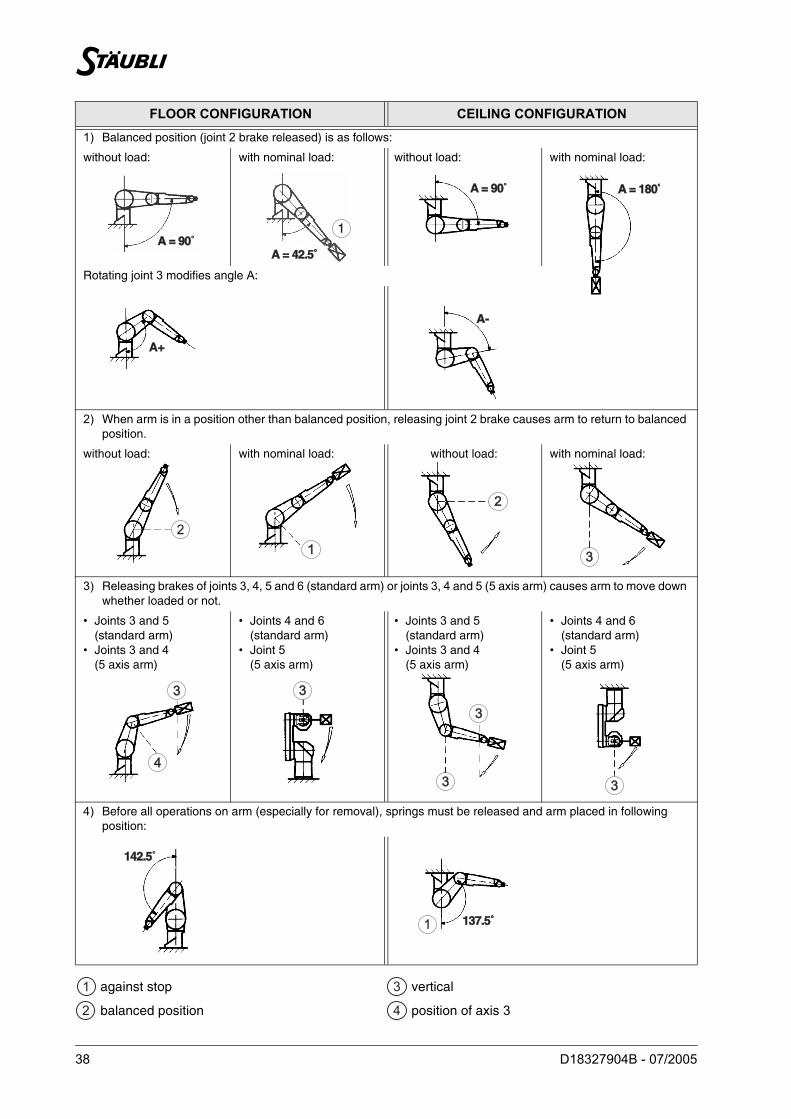
FLOOR CONFIGURATION CEILING CONFIGURATION
1) Balanced position (joint 2 brake released) is as follows:
without load: with nominal load: without load: with nominal load:
Rotating joint 3 modifies angle A:
2) When arm is in a position other than balanced position, releasing joint 2 brake causes arm to return to balanced position.
without load: with nominal load: without load: with nominal load:
3) Releasing brakes of joints 3, 4, 5 and 6 (standard arm) or joints 3, 4 and 5 (5 axis arm) causes arm to move down whether loaded or not.
• Joints 3 and 5(standard arm)
• Joints 3 and 4(5 axis arm)
• Joints 4 and 6(standard arm)
• Joint 5(5 axis arm)
• Joints 3 and 5(standard arm)
• Joints 3 and 4(5 axis arm)
• Joints 4 and 6(standard arm)
• Joint 5(5 axis arm)
4) Before all operations on arm (especially for removal), springs must be released and arm placed in following position:
against stop
balanced position
vertical
position of axis 3
A = 90A = 90˚A = 42.5A = 42.5˚̊
1
A = 90A = 90˚ A = 180A = 180˚̊
A+A+
A-A-
2
11
22
33
33
44
33
33
33 33
142.5142.5˚
137.5137.5˚̊1
1
12
B3
B4
Chapter 1 – Description
D18327904B - 07/2005 39
1.11. SAFETY
The robot arm’s energy is that accumulated by the springs.
Indeed, joint 2 is equipped with a spring balance system. Releasing joint 2 discharges the accumulatedenergy. This energy label is attached on the arm and must remain in place.
The brake release movements are described on the opposite page according to arm configuration (floor orceiling).

40 D18327904B - 07/2005

Chapter 2 – On-site preparation
D18327904B - 07/2005 41
CHAPTER 2 –
ON-SITE PREPARATION
42 D18327904B - 07/2005
Figure 2.1
Chapter 2 – On-site preparation
D18327904B - 07/2005 43
2.1. WORKING SPACE
The robot like any fast moving machine, may be dangerous. Always comply with the safety standardsrecommended for robot use and inform operators about the dangers faced.
"Users must ensure that personnel who program, operate, maintain or repair the robot or the robot equippedcell are properly trained and have the skills required to perform these tasks safely" (excerpt from standardNF EN 775).
2.2. ATTACHMENT (figure 2.1)
The robot arm can be installed vertically, base downwards (floor-mounted version) or base upwards(ceiling-mounted version). In all cases, it must be securely attached by 4 class 12.9 M16 hex. socket headscrews.
Attachment surface shall be flat and metallic. A deformable support will greatly reduce robot’s performancein speed and accuracy.
To dimension the support, take into account the maximum loads generated by the arm in motion at point 0which are:
under following load conditions:
The user can accurately position the robot by means of two 16h8 diameter centering pins.
DANGER: The arm's working area must be surrounded by a closed safety enclosure incompliance with the country's safety legislation preventing personnelaccessing the dangerous area.International standard: ISO 10218 (1992).French standard: NF EN 775 (1993).European Directive: machine directive CEE 98-37.
DANGER: There must be no obstacles within the robot work envelope.
STANDARD AND L ARMS
FV 4067 N
FG 2456 N
CB 3706 Nm
CP 2012 Nm
LOAD POSITION (mm)
LOAD (kg) AXIS 5 AXIS 6
Standard arm 20200 100
Arm L 14

44 D18327904B - 07/2005

Chapter 3 – Installation
D18327904B - 07/2005 45
CHAPTER 3 –
INSTALLATION
46 D18327904B - 07/2005
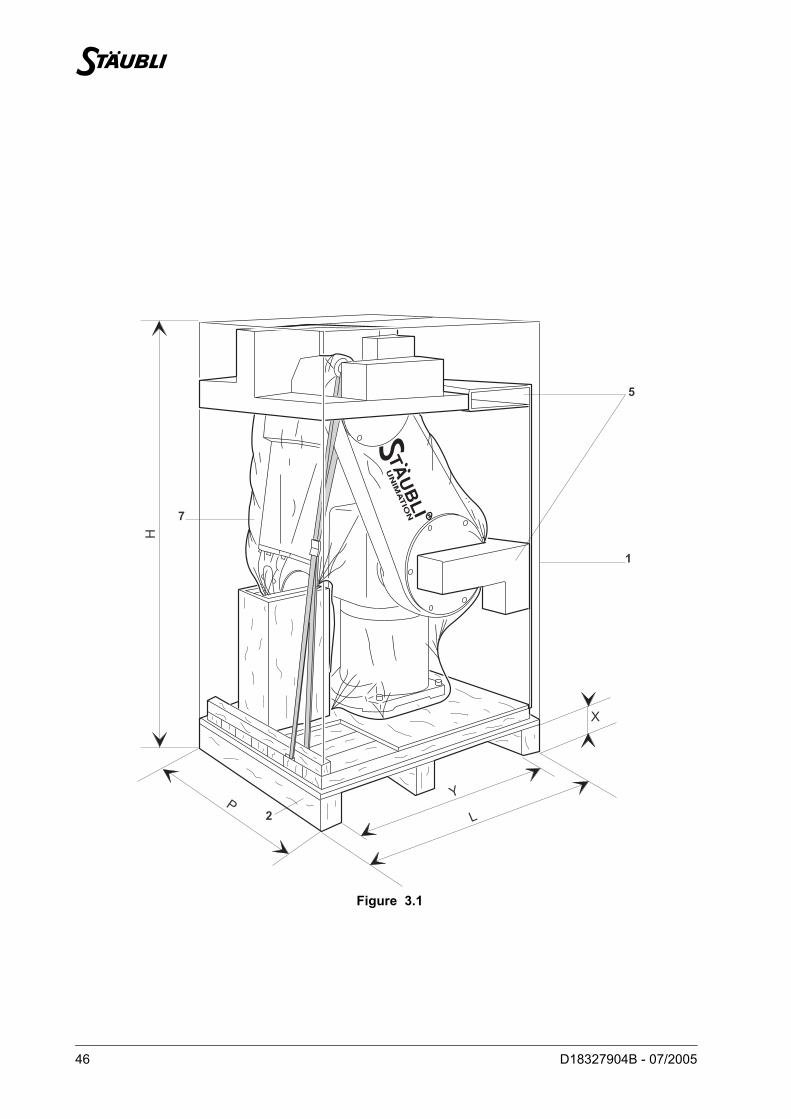
Figure 3.1
L
X
5
1
7
2
YP
H
Chapter 3 – Installation
D18327904B - 07/2005 47
3.1. ARM PACKAGING (figure 3.1)
Standard packaging:
International packaging:
The arm is packed in the vertical position. It is attached to the pallet (2) by 4 M16 bolts (3).
Transport condition:
• Minimum temperature -20°C• Maximum temperature +60°C
3.2. HANDLING OF PACKING (figure 3.1)
By pallet truck under base (2).
STANDARD ARM ARM L
Case (1) L x H x D 1200 x 1570 x 1000 mm
Gross weight 323 kg 325 kg
STANDARD ARM ARM L
Case (1) L x H x D 1290 x 1570 x 1000 mm
Gross weight 391 kg 393 kg
STANDARD AND L ARMS
X 100 mm
Y 1040 mm
48 D18327904B - 07/2005
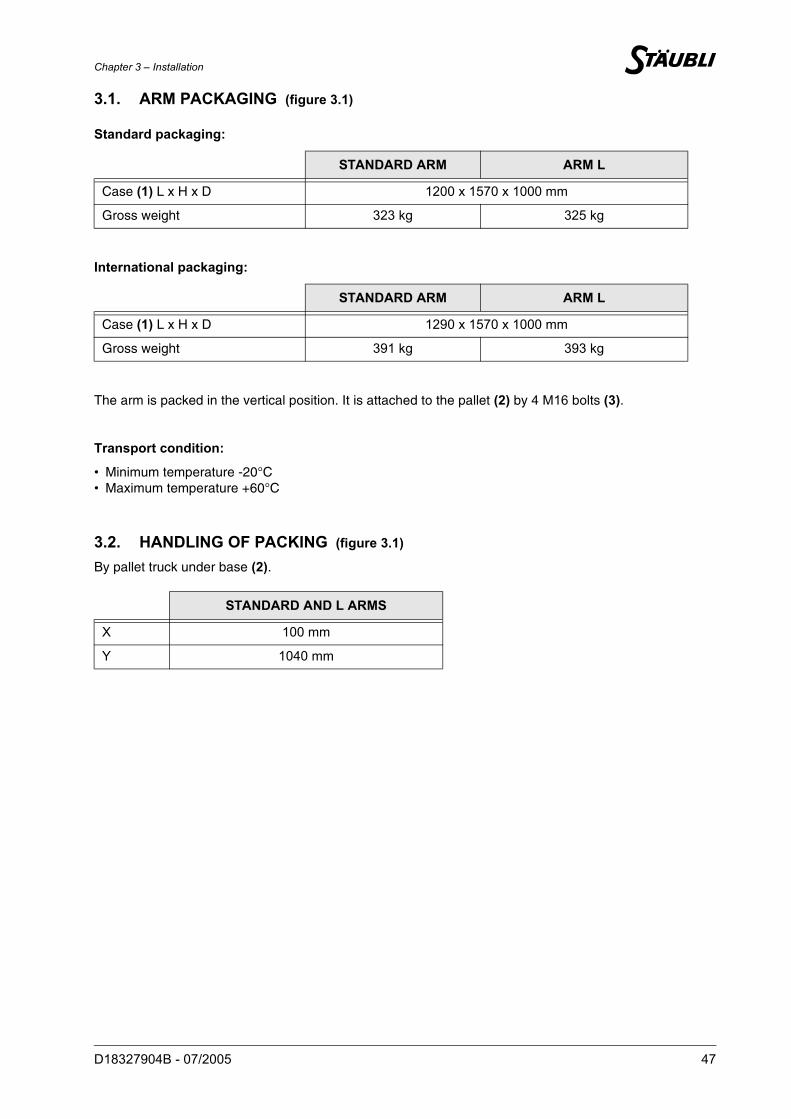
Figure 3.2
Figure 3.3
6
3
4
Chapter 3 – Installation
D18327904B - 07/2005 49
3.3. UNPACKING AND INSTALLATION OF ARM
• Move the packing case as near as possible to the installation site.
• Remove the cardboard packaging (1), remove the packing material (5) and the plastic cover (7)(figure 3.1).
• Pass the hook (4) of the hoist through the hoisting ring (6) and hold slightly tensioned to stop the arm fromtipping (figure 3.3).
• Remove the (3) bolts from the arm (figure 3.3).
• Slowly raise the arm using the hoist.
Attachment point
Center of gravity
CAUTION: According to European Directive CEE 98-37, the hoisting ring’s (6) threaded hole (M20)used for the robot hoisting is defined according to the ISO 262 standard.
CAUTION: The robot will swing when raised and moved (figures 3.2 and 3.3).
CAUTION: For ceiling-mounted version robots (balance springs of joint 2 released), do not rotatejoint 2.
BA
BM
50 D18327904B - 07/2005
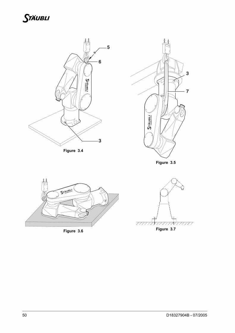
Figure 3.4
Figure 3.5
Figure 3.6 Figure 3.7
6
3
5
7
3
Chapter 3 – Installation
D18327904B - 07/2005 51
3.4. INSTALLATION OF ARM
3.4.1. INSTALLATION OF ARM ON FLOOR (figure 3.4)
• Position the arm on the support at its final attachment points.
• Attach the arm with 4 class 12.9 M16 hex. socket head screws (3), tightened to 325 Nm ± 23 Nm.
• Unscrew the hoisting ring (6) and install the plug (5).
3.4.2. INSTALLATION OF ARM ON CEILING
• Carefully lay down the arm on a flexible support as shown on figure 3.6.
• Place the fabric sling (7) around joint 2 as shown on figure 3.5.
• Position the arm on the support at its final attachment points.
• Attach the arm with 4 class 12.9 M16 hex. socket head screws (3), tightened to 325 Nm ± 23 Nm.
• Tension the springs for robots delivered in ceiling-mounted version using the tool supplied with the robot(see chapter 3.5).
3.4.3. MOUNTING FLOOR QUALITY
(figure 3.7)
The user has to make sure that the mechanical caracteristics of the floor and the means of fixture allow tohold up the maximum forces caused by the moving arm (see chapter 3).
CAUTION: The arm can be attached with the base downwards (floor-mounted version) or with baseupwards (ceiling-mounted version). Caution: the balance system is installed in thefactory for one OR the other of these versions. Conversion from a floor-mountedversion to a ceiling-mounted version requires a mechanical operation on the balancesystem.
DANGER: For safety reasons, hold the sling slightly tensioned until arm is securelyattached to the floor.
CAUTION: Do not rotate joint 2.
CAUTION: 500 kg fabric sling.
DANGER: For safety reasons, hold the sling slightly tensioned until arm is securelyattached to the ceiling.
CAUTION: The height of the robot support can strongly influence the forces on the floor.
52 D18327904B - 07/2005
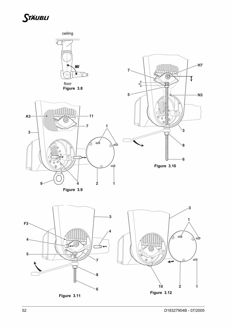
ceiling
floorFigure 3.8
Figure 3.10
Figure 3.9
Figure 3.11Figure 3.12
9090˚
6
N3
H7
8
3
7
5
x
7
A3
3
1
9 24 1
11
F3
4
5
6
8
7
4
3
210 1
3
1
Chapter 3 – Installation
D18327904B - 07/2005 53
3.5. SPRING TENSION
Figure 3.9
• Remove hoisting ring (9) from the arm.
• Unscrew the M5 screws (1) attaching cover (2).
• Remove cover (2) from arm (3).
• Remove the 2 pins (4) from arm (3).
• Remove foam (A3) wedging beam (7) against arm (3).
• Check that beam (7) and its springs (11) are not jammed in arm (3).
• Place the robot in position (figure 3.8).
Figure 3.10
• Unscrew the M12 nut (5) from the M12 threaded rod (6).
• Insert threaded rod (6) into arm (3) (polyamide washer in contact with arm).
• Screw nut (5) onto threaded rod (6).
• Screw the end of threaded rod (6) into beam (7).Grip length X = 15 mm ± 1 mm
• Tighten nut (5) against beam (7).
• Using an 18 mm ring spanner (not supplied), tighten nut (8) until the pin holes of beam (7) coincide andpass beyond (± 1 mm) those on the arm.
Figure 3.11
• When beam (7) is in position, insert the pins (4) in arm (3) (pin threads on outside). The pins must beinside face (F3) of arm (3).
• Unscrew nut (8) so that beam (7) bears on pins (4).
• Unlock nut (5).
• Unscrew threaded rod (6).
• Unscrew the M12 nut (5) from the M12 threaded rod (6).
• Remove threaded rod (6) from the arm.
Figure 3.12
• Install cover (2) on arm (3).
• Tighten the 3 screws (1).
• Install plug (10) in arm (3).
CAUTION: The robot must be attached to the ceiling. Do not rotate joint 2.

54 D18327904B - 07/2005