Embed Size (px)
DESCRIPTION
It is a manual for design of Armaments and war equipment
Citation preview

UNCLASSIFIED
AD NUMBER
AD830272
NEW LIMITATION CHANGE
TOApproved for public release, distributionunlimited
FROMDistribution authorized to U.S. Gov't.agencies and their contractors; CriticalTechnology; AUG 1964. Other requests shallbe referred to U.S. Army Materiel Command,Attn: AMCRD-TV, Washington, DC 20315.
AUTHORITY
USAMC ltr, 2 Jul 1973
THIS PAGE IS UNCLASSIFIED
? Al , l •-f AMCP 706TH S3 V; A 1FR."A NT WITHOUT CHANg Oi OROP 20- 1O0
ENGINEERING DESIGN HANDBOOK
Eý LEM ELBTS OF AiRMAMENTIENGliNEERINGPART ONE
SOURCE'S BF ENERGY
D
S- ,,',, l "' c c'i• •" •• C'l C oP
F1 . ,t P• •- ,,8A IM.C
tit), 8o .
) KEAD(AJARTERIS, U. S. ARMY MATERIEL COMMAND* AUGUST 1964
2 KbJtITE RS
*~-fl. &L VLL..JnLcL C-.JhLANAOI J
V ~~WC1 ND.C. 20315
31. August I%
,~> 061. ?1rei'~of Armament Engi-neering, Part One,$'AJ.CWLJ. 1ormn part of the Arlmy Materiel Co-mrmad
Ld b o3~ M acbok S3eriesa is ~a dbished for the. info-.mation.,ji.rc cc a>ozrcd
SEW SIATH JR
SZEYN D2. STHJ.Major Genler~al, USAChief of Staff
I31 I en" G
Chief, IN.dinistc;r at iv e Office
L $STRLUTIOM pocial
5nOTi

BestAvailable
Copy
FORE WOR.D
This handbook is one of a aeries of three compriming E' zmantsof Armament Engineoring and forrmis part of the Engineering DesignHandbook Series of the Army Matt.riel Command.
The three Parts of Elemer.ts of Armament Engineering wereI £ produced from text material prepared for use at the United States3Military Academy. They are published as a part of the Handbook
if Series to make generally available the wealth of fundamental infor-.mation contained in the text material, which is of value to those con-cerned with military design, particularly to new engineers and tocontractors' personnel. I
Arrangements for publication of the handbooks comprisingElements of Armament Engineerimj were made uuiier the directionof the Engineering Htandbook Office, of Duke University, prime cou-tractor to the Army Research Office-Durham.
Agencies of the Department of Defense, having need for Hand-books, may submit requisitions or official requests directly toPublications and Reproduction Agency, Letterkenny Army Depot,Charnbersburg, Pennsylvania 17201. Contractors should submitsuch requisitions or requests to their contracting officers.
Comments and suggestions on this handbook are welcome andshould be addressed to Army Research Offic,-- Durham, Box CM,Duke Station, Durham, North Carolina 27706.
Ii
4" ".i

FOREWORD TO ORIGINAL
TEXT MATERIAL
-A-T tat has been reV'ared to meet a specific development and changes in the field of wea-requirment as a reference for instruction in pons design.
_',ements of Krmament gmgineering,.A one- References cited are those available to theemater course in applied engineering analysis student as the result of stud7 in previpus coursesoAdutcd by the Dearbuent oi Orchumce at at the United States Military Academy. Advancedtha 'United States Military Academy, for mem- references are available at the Department ofbers of the First (Senior) Class. it represumts the Ordnance Reference Boom.
ipplaticon of military, scentific, and engineer-ig,- fundamentals to the analysis, design and op- Contributing anthors foi 19•8-59 revision are:entire of weapons systems, including nuclearcmapoments. It is not intended to fully orient Maj. W. E. Rafert, Ord Corps Asst. Professoror familiarize the student in weapons employ- Capt. A. W. Jank, Ord Corps Instructoram or nomwaltw'e.,, Capt. C. M. Jaco, Jr., Ord Corps Instructor I
0•-a y, the larwe v~lume of cassified Capt J. M. Cragin, Ord Corps Instructor T,
used in presentaiiw3 c; this course has been Capt G. K. Patterson, USAF Instructorovat~d; hence the tert is iatended to serve as a
of ,,A- pa--s-rcoamx. d•scussions. The JOHN D. BILLINGSLEYt is revised annually b,- intuMctois -f the .Colhel, U. S. ArmyDepartment of Ordnance ; -An efiort to sisure Professor of Orýnanceta subJect presentafnio will keep pace with August i958
S
7|
6: j
PREFACE
The usefulness and dependability of systems which serve man are contingent upon the effectiveperformance of the components wh.uh make up those systems. So it is with the weapon systems ofwar. In centuries past, vast effo-t has been expended in improving the performance of war machines.Improvements of this century have included rigorous a-pfication of scientific principles to warfare inan effort to optimize the performance of mechanisms of war. As the laws and rules of mathematics,rphysics, and chemistry have been applied to war and its machines, war has become more complexand more deadly.
Perhaps no component of weapon systems has been studied more thoroughly than sources foemwhich energy can be conveniently and quickly liberated in great quantity. From the days of Crecyin 1346, when guns began comnpetition with sharp-edged weapons, until the end of Word War-IIwhen 85% of the casualties were attributed to convention ) explosives, the trend toward var andimproved explosive has continued. Since 1945, the use of atomic energy has opened a vv-t newmagnitude of effectiveness from a new source of energy, the atom and its parts.
In this portion of the text those fundamental facts which must be known to permit the studeutto understand how energy is stored, liberated, and applied in military devices will be discussed. "11osfacts incluJi a discussion of the theory of the release of chemical and nucle&Ar energy, thzmochemis't'r,explosives classification, and the properties of representative explosives.
A reasonable knowledge of all these fundamental facts is required if the military leader is -tounderstand the performance, a& well as the capabilities, of 6-r increasingly complex weapons.
The study begins with a review of the theory of basic chemical energy reactions as they applyto explosives.
LW .. '..
iI
Li _

TABLE WF CONTEWTS
SPi•uagrph POP*1 CHAPhhR 1
THE THEORY OF CHEMICAL EXHOhIVE REACTIOWb
1-1 INTRODUCTION . ... ... ............ ........... 1-i
11-2 HISTORICAL NOTES ......................................... 1-1
14 DEFINITION ....... .......... 1-2
14.1 Formatlon ot Gas ... ... ............................... 1-21-4 '2 Evolution of Heat . . . ... .. ...... ...................... ...... ...... 1-21-3.3 Rapidty of Reaction ........... ........... ...... 1-2
-1.F I Initiation of Reaction ... .......... . ............................ 1-2
14 CATEGORIZATION ............ ..................... 1-4
1-4.1 Low Explcmsives .. ... ......................................... 14-
14.2 H igh Explosives ............ ... ........................................ 4
1-5 CHEMICAL KINETICS .............................. .......... 1-5
1-8 PROKFJTI'S OF MILITARY CHEMICAL EXPLOSIVES ... 1-7
1-8.1 Load Demt.-t (Iligh Explosives) ........................ ............... 1-7
1-8.2 H ygroscopicty ............................ .................................. 1-7
1-8.3 Sensitivity .. ................................... 1.7
1_..4 Velocity of Detonation ............... ....................................... 1-7
1-8.5 Strength .... . ................ ....... ............................ 1-8
1-8.6 Brisance . .. . ... . .... ..... . ... ........ 1-8
1-0.7 Power ... .......... . ....... ............... .. . 1-8
1-0.8 High Order of Detonation . ......... ...................... 1-8
1-..9 Low Order of Detonation .................................... 14
1-6.10 Stability .. .. ...... ..... . ....................... 1 -41-7 FfXLSIVE S iRAINS .. ............................... 1-91-7.1 Propelling Charge Explosive Train ............... .. . ...... 1-9
1-7.2 Berting Charge Explosive Trains ............................... 1-11
2-1 CHEMICAL REACTIONS OF EXPLOSIVES ....... ................ 2-I
V

TABLE OF CONTUNTS (cont)
Paragraph Page
Chapter 2 (adt)
2-2 REVIEW OF BASIC DEFINITIONS ANDCHEMICAL IUNDAMENTALS .21
2-2.1 Gram Molecule 2-2
• 2.2 Gram Formula Weight 2-2
?...3 Specific Heat 2-2
2-2.4 Molecular Specific flest . ....... 2-2
2-2.5 Speific Volume 2-2 A
2-2.6 Molecular Volume .......... ....... 2-2
2-2.7 Co-volume .. ........................ 2-2
2-2.8 Speciic GrPvity 2-2
2-2.9 Density 2-2
2-2.10 Density of Loading 2-2
2-2.11 Calorie .. ........... .... ..... -3
2-2.12 Kilocalc.ie ............ ...... 2-8
2-2.13 Heat of Formation .................. .............. 2-3
2-2.14 Principle of Initial and Final Stat. .......... 2-3
2-2.15 Heat of Reaction .. . ................ 2-3
2-2.16 Potential of an Explosive . .. .......-
2-3 POTENTi-AL 2.. .....................-....... ....... . 24
2-4 QUADITITY OF HEAT LIBERATED ATCONSTANT PRESSURE ....... ............................ 2-4
2.5 VOLUME OF GAS LIBERATED ................................. 2-6
2-8 EXTERNAL WORK PERFORMED IN EXPANSION ....... 2-7
2-7 QUANTITY OF HEAT LIBERATED ATCONSTANT VOLUME ..... ..... ........ 71.7j 2-8 POTENTIAL OR W ORK ............................................. 2-8
2-9 SUMMARY OF CALCULATIONS ...... ... ................ 2-8
2-10 TEMPERATURE OF EXPLOSION ............................. 19
2-10.1 Temperatum- When Solid Products Are Formed ............. 2-.
2-11 DETERMINATION OF PRESSURE IN ACONSTANT VOLUME CHAMMER ................................. 2-12
2-11.1 Basic Equations ................................ .. 2-12
2-11.2 Pressre in a Gun Propellant Chamber ............................ 2-1"
vi
TABLE OF CONTENTS (ount)
Pamgraph Fare
Chep. 2 (c.nt)
?-11i. Plsriure 'Aen Solid Pioducts Are Formed .. ....... 3..... 2-14
2-1.4l Actual Chamber Pressure . ........................ ...-. 5...
2-12 DETERMINATION OF WORK IN A SYSTEM OF1CHANGING VOLUME AND PEESSURE .2....................... 2-15
i:. MLIUTARY IJPLOSIt CHARACTiRISTICS
.. 3-1 INTRODUCTION .. .. ... ..... . ... .... .. ........ ...... ...... 3-1
3-2 H IG H EXI L SIVES .......................................................... 8 -1
8a- 1 Greate Potential ............ .............. .. ........ 8.1
3- HIGH EXPLOSIVE CLASSES ......................................... 3-
W-3 Primary High Explosive ...................................................
83 .2 Secondary High Exp!osive ..................................................... 8-4
S3-L Comparison of Et ple.h.es ............ . . ........... ....... ........ 3 -4
" "3SC-4 PRIMARY HIGH EXPLOSIVES ........................ . ............
&-4. Men-y Fuolunenate ..(.N..T .......................... 3-
8.4.2 Le d AzidTe .. ........... . .. . . . .. .... .................... 3-8
8-43 Lead Styphnate . ....... . ........ .......... ......... 8.. 4
S3-5" SExoDARY HIGH EDLOSIVES .........................................- 3-7
3-5.1 T6.ryl .... . ......... . .. .................. ........................... -7
3.5.2 Trinirotoluene (TNT ) ............ .............................. .............. -7"s- 3~ Tetryt• ] . ... ......... .. ... ..... .. ............................................ a
q4s.4 Axm tol .. .. .. -.. ... ... .. ............ ....................... ...... .................... & S
"8.5. xoi D.............. ...... .. . .....................
3-.7 PETN .......... .. ...................................... . ... 3. 1034 8 Penimlite ... .... ....... ..... ............................. ........ ..................... &-!0
3.5.9 H M• ... ... ........ ............ .................. .................... . ........ 3-10 t
3-21.10 D ynrunites ..... .. .. . ........ ...... . ... ..................... ......................... 3-11 !
LIQUID HIGH EXPLOSIVES .................................................. s
-.7, METAL-HIGH EXPLOSIVE MIXTURE ........................... 3.... 3-1
S8.7.1. Explove Manufadvbng C u................................ $
Svis

TABLE OF CONTINT (Cont)
Parmgph Page
3-8 LOW EXPY,OSPiES OR PR.Y'ELLANTrS . 3-13
,-.1 Controlled Bwudbg 3-14
.4A. Sensitivity .. 3-14
3.8,3 atcbil•ty ... .. .3-143-6.4 Rt'idiie .. . . .. . .. .. .... 3-1h
3-8.5 Mamf-acture ...- 14
3-8.6 Ernsive Action . ... -14
3-8.7 Flash .. ..... ..... 3-14
3.8. Detonation .... 3-14
3-8.9 Smoke 3-14
3-9 BLALCK POWDER 3-14
3-10 SMOKELESS POWDERS 3-15
3-10.1 Bunting Time ............ 3-15
3-10.2 Burning Action .. ........................ 3-17
3-10.6 Degressive Burning ......................... 3-17
3-10.4 Neutrzl Burning 3-17
3-10.5 Progressive Burning . . . ............. 3........ 8-17
3-10.8 Web Thiciment ......... . ...... . 3-17
3-10.7 Single-Base Propellant-; ...................... 341b
3-10.8 Double-.tase Prapellants 3-19
3-10.9 Ball Powder . ....... .... 3-19
3-10.10 Nitroguonldine Propellants ........................ 3-19
3-11 LIQUID GUN FROPF 1.A24rs -3-20
3-12 CUN PROPEL!,ANT IMPROVEMENTS .............. 3-21
3-12.1 Flesh 3-211
3-12.2 Smake 3-2A
3- .2.3 Higher Potential .- 2
& 12,4 rosion .... ...... ,4
3-12.5 G!.fater Stability 3-2.3
-3-13 PIPPELLANTS FOR RO('T .. ..............
3-13.i ,.,irren. S d Propelharas .. 4.4..... ... .......................... 3-24
•!R.VU Cur',,mi Liquid Propdants ..................... 3-25
V:€,
TABLE OF CONTENTS (cont)
Paragraph Page
chaptw 3 (€ont)
-3-14 EXOTIC PROPELLANTS 3-26
M'14. Wtal Additives 3-273-i41.2 Fluorc Compounds 3-27
2-14.3 tF!ee Radicr c 3-27
3-44.4 Ionic Fues 3-27
FL~wIN-?U*tO RIACOIONS
4-1 INTRODUCTION 4-.
4-2 ATO)MIC STRUCTURE 4-2
4-2.1 Elements and Atoms ........... 4-2
S-2.2 Nuclear Compcsition ............. 4-2
"4-2.3 Isotopes 4-3
4-2.4 Symbols 4-3
4-17.5 Mass of Nuclear Part:ces ............. 4-8
,4-2.6 Charge of Nuclear Particles 4-4
4-3 RADIOACTIVITY 4-4
"4-3.1 Nuclear Instability ....................
4-3.2 Alpha Decay .... . ................. 4-4
4-3.3 Beta Deiay ... . .. 4-4
4-3.4 Gamma R&ys .. . 4-4
"4-3.5 Indtuced Reactions 4-5
4-3.6 Radioactive Series ............. 4-5
a4-4 ENERGY, FISSION, AND FUSION . . .. 4-S4-4.1 Equivakluce of Mass ard Energy 4-5
S4-4..• Fission . 4-7ECTON, FuTion I.....441
4-4.4 Nucear Energy . 4-8
44 -ROSS SETOTECANREACTION,Ai'4D CRITICALITY 469
4-.-1 Cross Section 4-9
44.2 Chain Reaction - 4-10
!ix
IfABLE Of CONTI•.T5' (cont)
?amafoph Page
Cbip.r 4 (gat)
4-5.5 Neutrn Reactions . ....... 4-10
4-5.4 C~usses of Chain Reactions and Criticaity ................... 4-16
"45.5 Means of Ix•aasing Criticalty . . ............ 4 -I1
EXPLOSIV AHNEV I'U).IVE MAW¶FACTURI AND TISTINO
A-I INTRODUCTION ................. A-I
A-2 MANUFACTURE OF TRINITROTCLUENE .......... 1
A-3 M&NUFACTURE OF SINGLE-BASE PROPELLANT ...... A-2
A4 MANUFACTURE OF PERCHLORATE PROPELLANT ...... A-
A-5 PHYSICAL TESTING OF EXPLOSIVES ...................... A4
A-5I Sensitivty to Sl--,ck ............... ................ A4
A-4 2 Tramuz Lead Bkx s ........... ................................ A-4
A.5.S Bsflhstlc m ortas.... ....... .... ................... A-4
A-5.4 Velocity of Detonation ... ............ ................. .. I,-4
A.&5 Rela•ve Briun ............. .............. A-4
A-5. Additiota! Tests ............ .. . ... .............................. A-8
A-8 PHYSICAL TESTING OF ROCKET PROPELLAMTS. A-8
A-00 Solid Prpe " T-3ý g .. A........ . ............................. A-8
A-Si Measurement of Burning Rates .................................. A-8
APPENDIX ................. A-il
INDEX ........................... I-1
x
=I
t7
t .~ LIST OF ILLUSTRATIONS
Fig. No Title Page
1-1 Schematic drawing of detonation showing pr)gress through acolumn of explosive 1-4
1-2 Nitroglycerin 1-5
1-3 Toluene and trinitrotolueý:.e 1-6
i1-4 Mercury fulminate and lead azide 1-6S1-5 Explosive trains 1-10
S1-6 Schematic representation ut explosive trains 1-11
Curves showing vari'tion of mol specific heat with temperature
Sfor several gaseous --" losive products 210
S3-1 Effect of oxygen bal~nc, on suength of explosives (comparedwith TNT) in the lead block expansion test 3-2
3-2 Schematic representation of mercury fulminate 3.5
3-3 Lead azide-
-4 Lead trinitrorescorcinate .6
8-5 Tetryl 3-7
3-1 Trinit-"t1zuene (TNT) 8-
A3- Anmonium picrate (Explosive D) 8-8
3-8 Cyclotrmnethylenetnnitraminc (RDX) 3-9
3-9 Pentaerythritetranitrate (PETN) 3-10
3-10 Cyclotetrarnethylene tetranitrLmine (HMX) 3-i0
341 Ty.•Ical shapes of powder grains 3-18
3-12 Sizes of some typical grains 3-16
3-13 Web thickness and route of burning progress through aprogressivel, burning grain 3-16
3-14 Relative areas of burning as a function of percent of individualgraiu ccnsur.ed, for several 'ypical grain shapes 1,17
3-15 Flash suppressor on 75-mm gun tube 3-22
4-1 Isotopes of hydrogen 4-3
4-2 Uranium ( +N + 2) series 4-0
S4-3 Pseudo-continruous plot of average ma:s per nucleon versusao-iic nun±• 4-7
4-4 Bunticles entering a slab of material 4-9
t - ,ci

I:
LIST OF ILLUSTRATIONS (cont)
Fig. No. Title Page
4-5 Idealized neutron pipulation growth 4-11
S A-i Trn-nitration equation showing some typical polyn;rxotoluenes A-2A-2 TrauzI lead block after test, with section showing expansion
of cavity by explosive A-7
A-3 Ba1-tic mortar A-7
A-4 Pressure vessel for measuring burning rate: of propellant asa function of pressure A-9
* A-5 The effect of pressure on burning rate of a rocket solid propellant A-10
Xii

CHAfl 1
THE THEORY OF CHEMICAL EXPLOSIVE REACTIONS
1-1 INTRODUCTION
In explosive chemistry the energy released by How this energy is best contained and con-* rapid chemical reaction is used ko provide heat, trolled is left to later chapte-s on exterior
ballistics, principles of propulsion, and gunexpand gas, create bi.st and shock, provide larel design. This chapter discusses how such
fragmentation and fragmentat'cn velocity, and energy is stored and liberated, and how
to crepte forces for propulsion. can be done efficiently, safe)/, ad conveniently.
1-2 HISTORICAL NOMtS
CreAt strides forward have been made In T. J. Pe!nze, a Frenchman, and later the do-explosives sinco their inception. Th. earliest veiopuxent. in 1846, of nitroglycerin by an Itlian,known explosive, called gunpowde oa, black Asranin Sobrero. It remained for Alfred Nobelpowder, is generally conceded to have Lbcen t-. (183- lVYX of Sweden, a mat of practical asmixt.ure of saltpeter, sulfur, and charcoai firs' well cs scientific bent, to develop exp-izdves ofdescribed by the English friar, Roger Bacui, in usable physical properties from nitrogiyaerin.the year 1242. This mixture, at that time, was Nobel included among his many accomplitk,-not thought 3f as a propellant, but rather as an rits (1) the method of initiating high explkisvestewplosive which w,-uld cause terror among th. by detonation to secure their full power, (2) theenemy with its bright flash and hu•ndering noise. thenmy of explosive action; (3) the productlomTo Berthold !chwartz, a Germa ixnonk, is given of dynamke; and (4) design of double-baenthe credit for having invented, about 1313, a propellants.
ireanmn usi.g gunpowder as the propellant. Thefirst organized use of gun- in open battle was The great number of achievements in the'by the English at the Battle of Crecy in 1348. science of explosives accelerated by two geet
erior to the military use J e-plcsives, which world wars, make nece-wry t second look atwus as early as the seventh century, there were the basic chin~es which bzve taken place inrecorded &"s o chemlca1b in f:,nw .t*h m the ield of military explosives. W.Crld War I"Gr,+ hm. mad Chbnse ivaket-propehled ^fire was fought with unly a W standard higharrows. Tle prinicpal ingredient of Greek fure exp)osives, together with some Inferimor substi-vwas probabiy naphtha, mixed with sulfur avd lutes necessitated by material s4rtges. Theoopitch. Chinese rockets were propelled by a shortages permitted little chice of explesivu ••rcombination of sodium ch:rate or sodium ritrate Vpecial application or specf requireiitand some combustible material. These chemical TtAay the 36d has been eatiy enlargd Wthmixtures were the forernners of gnpowder. rrqny types as well as large numbers of ex4pl4wm
The discovery of gunpowder was followed in together- with niew inges and lnaei'wl sope1838 by ".be prepuration, of nitrocrc•ulosc by oi appiicanzon.
S~1-1
E
-. SOURCES OF ENERGY
143 DEFINITION
- An explosive is a chemical compound oa not an explosive since it d-es not evolve heatnditare which upon the application of heat or but rather absorbs heat during the reaction. To
shock decomposes or rearranges with exirerne be an explosive a substance must exhibit all of.kpidity, yielding much gas and beat. Many the phenomena mentioned: formaoir of gaes;
substances not ordinarily classed as explosivesmay do one, or even two, a, these things. A mix- evolution of heat; rapidity of reaction; aui -. ita-ture of nitrogen and oxygen, for example, can tion of reaction by shock or heat. To be a miiitarybe made to react with great rapidity to yield the explosive, an explosive must also be suitable forgaseous product nitc oxide, yet the mixture is and used for military purposes.
V-3.1 FORMATION OF GAS 1-3.2 EVOLUTION OF HEAT
The student is familiar with the burning of The evolution of heat during the ieaction
v.ood or coal in the atmosphere. In this reaction causes a large increase in ti,. temperatar, of thethe carbon and hydr6gen in the wood or coal gases. This .;ncrease results Ln die rapid expan-combine with the oxygen in the atmosphere to sion of the gases ud the generation of a veryfonrtr carbon dioxide a:d steam, together with high pressi,-e. A reaction which (ails to produceIlame and smoke. If the wood or coal is this high pressure will not fill the requirements)pulvIerized so that the total surface in contact of an expios-on.•,rith oxygen is increased, and it is burned in af"irnice or forge where more air can be supplied,the burning can be made more rapid and die - RAIDITY OF REACTIONcombustion more complete. If the wood or coalis'immersed in liquid oxygen or suspended in air Unless the reaction occurs rapidly the ther-in the form of dust, the burning takes placc with mally expanded gases will be aissipated in theexplosive violence. In each case t&e action is the atmosphere and there will be no explosion. Againsame; the burning of a combustib!ý *o form a gas. consider a wood or coal fire; in the fire there isTh"•. difference is the speed with which the re- evolution of beat and formation of gases butacion takes place. Thus, materials which will these are not liberated rapidly enough to causebum can be rn.de tc explode if sufficient oxygen an explosioa.is iade available rapidly. This fact is demon-strated by the explosion within internal combus-tion engines where combustible mixtures of 14 INITIATION OF REACTIONgasoline and air exlode to operate the engine.In coal mines mc thane gas and coal duit combine The fourth factor is the requirement that towifh air to produce explosive mixtures. and in qualify as an explosive the material must readilygrain el, vators minute particles of dust form undergo rapid reaction upon the application of
explosive mixtivres with air. Most v,-,osives a certain amount of energy, in the form of shock
utilize this pri-ci1o!e except for the fact that ti,-v or heat, to a Small portion of its mass. A macr.iai
usually cont-n' ý:-eir own oxygen integrally and in which the first three factors exist is not sritable
so are indeaenJent of oxygen suppiied from as an explosive unless the reaction can be made
th' air. to ocoir at will. " "
1-2

CHEMICAL EXPLOSIVE REACTIONS
1-4 CATEGORIZATION
The chemical decomposition of at explosive classified as low or high explosives according tomay take years, days, hor s, or a fraction of a their rates of decompo ition. Low explosivessecond. The slower forms of decomposition take btrn rapidly. High explosives ordinarily deto-place in storage and are of interest only from a rate. There is no sharp line of demm-cat.imstability standpoint. Of more interest are the b:tween low and high explosives. The propertiestwo rapid forms of decomposition, burning and of the explosive indlcate the class into which itdetonation. The term "detonation' is used to falls. In some cases explosives may be made todescribe an explosive phenomenon of almost fall into either class by the conditions underinstantaneous decomposition. Explosives are which they are indtiated.
1-4.1 LOW IXPLOSIVES 14.2 HIMON XPLOSIrMS
"Low explosives are those materials which High or detonating explosives decompw eundergo rapid decomposition by burning from almost instantaneously by a rupture or splittingthe surface inward. They are usually manu- of the molecule aged the rearrangement of thefactured in the form of "grains" and used as atoms into other molehcules, mostly gaseous.propellants. Consider chat a number of grains Piesent day explosive molecules arm com•rsedof powder have been placed in the breech of a of atoms, most of which are carbrn, hydrogesi -gun. Sufficient heat is applied so that the powder nitrogen, and oxygen. While carbon and hydro-will ignite. Ignition oa.zurs when a temuerature gen tend to unite with oxygen, nitrogen Usuallyis attained which will cause the combtvtibl.s ret~mns to its elemental form. The explosveto react with the self-contained oxygen to form molecule should be considered an unstable mole-gas and lberate heat. Since this heat canno, cule which tendz to revert ton a more stable state.escape because of the confinement of the breech, Thare are several theories as to the me--chan ofit will heat the next inner lay- r of powder ex- detonation; the following is one.posed by the burning away ni the original sur- (a) First phase. The first phase is intt*tedf.e layer, ignite it, further increasing and by supplying enough energy to an exploiv•,expanding the gases. This continues until the usually in the form of shock, so that the dis-grairn is completely consumecO; concurrently, ruptive forces set up within the molecule exceedeach grain ignites adjacent grains until the en- the attractive f£rces between some of the atoms,tire charge is consumed. W 1-'e confined these and decomposition is started. The tendencyindividual grains bum from the outside toward toward disruption is caused by the instability ofthe center at the rate of about 5 feet per second. the high explosive molecule. The molecudar andIn open air where the pressure will n•t rise atomic atbacive forces are be nornmal bondsappreciably the rate of -cm..bustion wowd be tying the molecule together. When they aneabout 0.01 feet per second. As the burning broken, and the molecule is reaWrm %'.ne -continues thu ugh th&,, harg-, the pressure and centrated energy is released, which dsrUpts ,temperature rise, aLx I.-,, truning becomes more adjacent molecules. If the initial shock waveand mor- rapid. The r•. ci-lring is approxi- energy is sufficient, this wave will emately doubled for ever NiC rnise in tempera- through the entire vaus of exp!csve until it hasture. This form of decomposition results in the completely detonated, provi-i',I the enagyliberatioa of large quantiUes of gas which yield released by the splitting of ine molecule ishigh pressures making the explosive valuable s• sufficient to detonate more t64 one adjacentI: a propellant. in the barrel of a gun, the shell will nolecule.begin to move before expansion is complete, (b) Second phase. lhe second phase of deto-"leaving room for more expansion and thus pre- nation consists of the f•o•-ation Ad exIasionventing the barrel from bursting. of gas molecules. When the orlgL,?!1 moleoul is
1-3
ORDP 20-106
SOURCES OF ENERGY
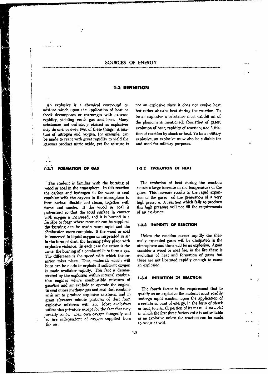
split, the heat of the detonating wave causes the not only this shock front, but also the chemicalcarbon and hydrogen atoms to oxidize thus ex- reaction zone (0.1-1.0 cm). Behind this detona-
panding their volume greatly. The entire process tiorn zone are the detonation products. In front
of detonation takes place almost instantaneously of the shock zone is the unreacted explosive
Explosives with extreme rates of detonation are in its original state of dernsity, pressure, and
no useful as propellants as the pressure developed temperature. At or near the beginning of the
would burst i~he barrel of a gun betre it ever- chemical reaction zone, the high temperaturecame w d irstia ofe b ell.ag bere e to which the material is raised by compression incame the inertia of the shell. the shock zone initiates chemical react~on. Maxi-
The mechanism of detonation may be visu- mum density and pressure occur at the beginningalized by referring to Figure 1-1. This figure was of the reaction zone, while the temperature anddeveloped from facts resulling frora hydro- velocity reach their peak at the compl-etion ofdynamic studies which showed that after the the chemical reaction. The detonation productsdetonator functioned, a detoi, tion zone which flow with great velocity (but with less velocityinc!udes a zone of chemical reactic, travels than does the detonation zone) thcough the un-extremely rapidly through the column of the detonated explosive. This is characteristic ofexplosivo. This detonation zone is generally detonation in contradistinction to deflagration, inconsidered to include t, very thin (10-" cmr) shock which case the reaction products flow away fromzone or shoc- wave. Lit'-e or no c:,,.!-icaI re- the unreacted material. The velocity of advanceaction occurs in 'his shock zone, but here pressure of the detonation zone is termed the detonationreaches its peAk. The detonation zone includes rate, or velocity.
-. •-'- .• '. .. -. .. .-..- . - . o ,JIDetonaatz Explosive
A Exploaive before detonation
D Detonation Zone 'ndeiouated E:,plosive
'.- Shock Zoae
s--- Cnemical Reaction ZoneI iDetonation Products
B - Explosive partiaUl detonated
Fig. 1-1 Schematic drawing of detonation hoawing progmss 0tmough a com.mi-
of expiosive.1 .xpo;,•
Lloo
'• CHEMICAL EXPLOSIVE REACTIONS
1-5 CHEMICAL KINETICS
Explosives are chemical compounds or mix- Heat and large quaatities of gas are liberated.tures of chemical compounds, and like different The reaction is repr(sented by the eqtlation:chemical compounds and mixtures have differentphysical cr-perties. Their melting points, freez- -NOi(N0 3E + 8C ---- 3K1SO4ing points, density, and chemical stability may (heat)vary widely. Of particular interest to the explo- + 2K,2C0 + 6C0 1 + 5N, + heatsives user is the stability of the explosive, forupon thi; property depends the power, sensitivity, App3cation over the years of these ideas toand ease of handling of he ammunition item in more complex organic compounds, containingSwhich the explosive is uied, within themselves all the required ingredients
Explosives and nr':Iellant,: generally ar,- .or ,-'action, has yielded a variety of explosivesorgsmade up o varying amounts :th a wide range of physical and reactiveSorganic compoundsmaeuofvrigront
Sof nitrogen, oxygen. hydrogen, carbon, and prLoerties. For example, the addition of nitrogen
metallic atoms. Some of the newer propellants, and oxygen in the form o -- NO2 groups to
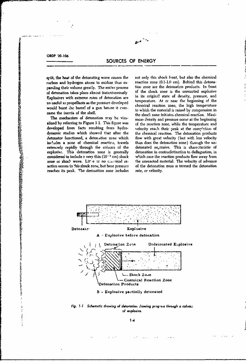
low exqplosives. contamn boron, lithium, and glycerin yields nitroglycerin.Sfluorine. The Lrrangement and proportion of The structural formula (schematic) of thisthese various basic constituents determine, in unstable, reactive explosive is:
large measure, the physical behavior of theexplosive.
As an integral part of nearly all explosives andof iandamental importance to the family of ex-plosive organic compounds is the intractable H H Helement nitroge.-. Unlike .ts behavior in air,which is four-fifths nitrogen, as a part of an H C -C - C - Horganic compound, aitrogen is not an unreactivebystander, but is combined with difficulry ond in 0 0 0relatively loose union ,vith its neiglkoring ele-ments. Its bonds are easily broken When these N N N
( I bonds are broken they ruptura suddenly and .
violently with the accompan:,ing liberation of 0 0 0 0 0 0relatively lagr. amounts of energy.
SAls' present ia most explosives is the elementL oxygen. Oxygen is relatively easily, but loosely, Note: One of the orygens in the nitrat groups is bound
"weakly to the N. This linkage is shown by thebound in union wilh other elements. It may be dashed line.joine't with nitrogen but can be caused to breakaway easily in order to join elements such as H,C, S, or itself A union of greater stability resufts. Fig. 1-2 Nitroglycerin.Fluorine when present is, like oxygen, an oxi-dizer. It tc'o rei,, ,ves electrons. Hence, in lermsof the reactivity of N and 0 the explosioa of The joining of additional nitrogen and oxygengunpowder can be explained. In the pulverized (nitrating) with toluene gives trinitrotoluwi e,
Z mixture c-f eharcomd 'C), sulfur (S), and salt- TNT.peter (KNO., potassm nitrate) are seen the Cornpa?,e nitroglycerin and trinitrotoluemt.requireents of unstable union of nitrogen, Both contain unstable nitrogen; both givc cabmixid so that excess S and C are readily avail-Abie appreciable energy when they rearrange. ii thefor a more stable xnion once an initiating impe- nitroglycerai the nitroge:. is linked only wVhtus, sucl as flame, is applied. The N breaks away, oxygen. Nitrogen would be in a more stablereuniting with either the sulfur, carbon, or itself' state if -ink', with itself; oxygen more stable if M
S1-55
SOURCES OF ENERGY
H HII IH-C- H- C -H
I IC C
H- C C H O2N C C-1NO2
C C
I IH NO2
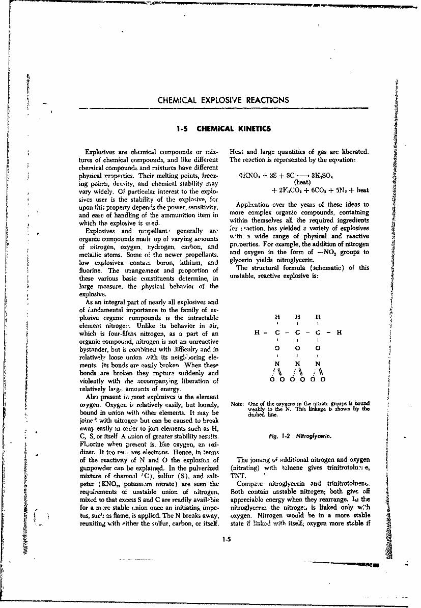
Toluene Trinitrotoluene
Fig. 1-3 To!uene and trinitrotoluene.
C=N-0-Hg-O--N-- NN
Mercury Fulminate Lead Azide
Fig. 1-4 Mercury fulminate and lead azid*.
joined with carbon or hydrogen; carbon and the reactivity or sensihv:ty of the compound.hydrogen more stable if bonded to oxygen. Thus The degree of ease of exploding unstablegreat instability exists and, as is well known, the chemical compounds may be an advantage or acompound is very sensitive or reactive and wil! disadvantage in the usefulness of an expiosive.explode when subject to even a jar. On the other The instability of the -C-O-N -0 linkageharid, the TNT molecule also contains nitrogen in nitroglycerin makes it easy to detonate, butin unstable union, but her. the link is with difficult to trAnsport. Thus, the end use of thecarbon. Also all carbon atoms aiz ioined into aring of carbon atoms, some bound by -. active explosive compound outen prescribes its con-double bonds. The ring (or cyclic) configuratioa stituency. In uses where extremely sesitiveserves also to hold the react:on prone "a,. -ns" of bu, easily detonaý-ed compounds are desired,
t.e molecule iarther apart, whereas in the •'.'4o- more unstable linkages and arrangements are
glycerin the 'arns" of e NO, groups we•+e prescribed.closer togethde. Hence, TNT, e'though ri-pi-ly In mercury fulminate for example, not omly isliberating large amounts ef energy antd gas when the 0 -- N bond easily broken, but mercu,-y, it.
once detonated, doe. not fracture easily and may noble metal, is only loosely joined with oxygen.he la,|dled without excessive danger. In lead azide the nitrogen atoms are mostly
In summary, it may be said 'hen thait the joined only with themselves. They 93e in only &.presevr. of unstable nitrogen awd other reactive weak union w.;d the lead, a meta) of !-w activity.elements such as oxyger, carbon, hydrogen, and These compounds are very unstable and ex-active metals is ez•ntial to expiosive compounds. tremely sensitive. These easily exploded com-TI T attie amounts of t&*ese elements, their ar- pounds are useful in smXll amounts to set off -
rangemnent within the conqpund, ard the nature larger amounts of less sensitive explosives, as willof their bonding all P-9ect the stabi'uity and thus b,.: seen in late," lessons.
-6
CHEMICAL EXPLOSIVE REACTIONS
1-6 PROPERTIES OF MILITARY CHEMICAL EXPLOSIVES
Almost all physical properties of an explosive he thorouighly wUaderb~cof-J The "'ore importantsubstance must be investigated to determine its characteristics are the load dei sity, hygrosco-suitability for military use. Before ..o explosive's picity, sensitivity, velocity of detonation, strength,
Ausefulness can be fully appreciated 'liese prop- brisance, power, order of detonation, anderties anid the factors which affect them should stability.
1-. ODDNIY HG XLSVS solvent meditumwhic];promnotes undesirable
istics of ~ ~ ~ ~ ~ th theinit patcfa high explosivev severa andrdu sisMtt~n ,ne-t a h-*gh explosive. Depending on the character- cooling reduces the tempe-rature of reaction,
rr-ehod ma beempoye, ie, ast pelet or locity of detonation. In the case of arrmmoniumprsssading. Shells loaded with '1NT require svetobcmsoientvehateywl
averge oaddensty f nt les 'an .52 detonate. In aldition, the presence of moisture(weight of explosive per unit violume in c,,, units)
pelet oadngandan verge oaddenity promotes decomposition, thereby affecting sta-lessthan1.5 wit thecasing etho ~ ilitN. Stilt another effect may be the corrosion of
loading. Armor piercing shells are press icaded th ea onann hee, o~ewith Explosive D resulting in an average load! 140, SENSITIVITYden~sity which v-iries from 1.45 to 1.55. An in- The term "sensitivity" as applied to explosivescrease in the loadI densitv of the charge is highl men'hvaewihwihte myb giedesirable. H-enct. by pressing. an average density o koac r nohrwrs h m~~ nof the load,,d charge is obtained which is greater intensity of shock, friction, o- heat rnquited forrthan the actual density of the particular explodzve or- det-onat-on. Whether an explosive isas listed in Table A'1 in the Annex to Part 1. sr~tv rntdpnsi atuo h oeHigrh load density reduces sensitivitv by making ua aeu fteepcie n louo uthe mass more resistarit to internal friction and 4rsa ieaddsotoc.un fcytlto the creation (of hot spots. By increasing t~i-e dni ,m~ i~r xeprrr' ihdncontinuity of tlhe exolosivtz mass, velocity of icesdmitrad~otxgo rsa.wtdetonqtion is increased, the loau is mnadc more 'a ~asmlrshtnewl e~ ordcdense, ,'nd the tendeney, fc-r Cavities to form iSseniiiy nrae meaueaddsotodecreased. Cavities may (ause o8iis-:res o,- PIC- o h rsaln t.c'r ilices esmature detonations. In addition. incr-ase.l lead ti ixTeszofhersalmyicraer
density permits the use of nio-e explossive in i - '~etesnii'm~dpri~ ntecspace providfd, the-eby ir -reasirng the strength pls'ucnierd*n hea utofnerlof the ammun't on. Giveyi t, (, ewlosiv'es of 'equ-il stansihn.obes ncytl.
pwrper , pand, it one has an ave,, uge dens-W-of 1.0 und the other 2.0 after lfoadIng. ~wicý h .. VELOCITY 0f PETONA1.ON
weight of the seconid eý.;piosive c~iru be carried it) WVhen a high exploiive detonates, the actionthe samnt space. Thuis, es&e'ntjiafi tliU' Utht precedcts in a wave thi-ouch the column of Zenergy to do work is ilvailablle 1.'-.ph-;;uv Th'e speed withl wliich this wave
1-6. HYGOS~~iVIV irOLwesses is terviez tile '\eloriltv of sletonat~on"is ~ ~ ~ ~ ~ ~ ~ 1 th0iad 'vofa ra I n i salu* -rSSCI in meters per second.
Hvgroscoepicitv stczL-y fan nlt Under ct~,~ i cnditicons, different explosiveiabsoilb moisture. 4t affects explosi'-ez 1), the (dol-tfttt- mt dif~'m eji~s(sec Table A-I inintrodoýIction of an im,'rt iajaterial which Wz.ten the tri~ne\ to Part 1). T"he factors which ma-vaporized absorbs heat, and by providing .~teriallv affect "he velocity cif detonatuon a!-e
IMM
SOURCES OF ENERGYIi reactivity, diameter of the column of explosive, of an explosive to ?.n da'~rthe close vicinity,
arnodsr-t of ý-onfinement_ crystal size, crystal or its qbflizv tc shatter r-s zovlnring mediumncoatirg, density, z~nd moisture. Increasin~g theexplosive column diameter, the wriount of con- 1-4.7 PGY#11ftfinement, or tht, densit-y will increase the ve]QWity. Power ^s deL~t8 as the rate of dcdng wAork.Moirture, coating o4 crystals, or decreasing theýThis Jefvo~ton applies to an expl osivi L well escrvstal size will decrease thc velocity, to a riachrte in e~rplosives powter is dependent
1-.5 STENT upvon s ~tb* and -detonation velocity, i.e., the.Arazot'it, oý eergy released and tý.e speed with
'the --'trength of an explosive 'Is as ua'ihky t(- do ,' hch 'i i~ e.ae.Srntbi~ne nwor'z. it may be defined and meatsau-red in twc powt-, ;tr closely -eloted. Geueaally speaking,wo,,'s. lFrom the user cr teting stan ipoint, it i.- giver ~-wn' .!plosives of equal strength, the one-Io';ied as the ab~ity of !hbe exploswive j displace de_'jruu~.ig at th,! highest velocity ilr-tolmie mediumr which confines .1'. From' thte engnnzer- have tne greatest brisance but will bz. rrortog roint of v~ew it is the amonoft of energy powe&1&s. It will be -nore brisant becai~se ofzib*;e 4 by the exp' .~isin or de' -- i, nation. The tl-e shwpness of thn 1)ov and snore powerfulŽýorstnwenf atoms aisi I'leir arrangement detcy- bemause of the speeiý with whbich the energy isninhes the energy available in an explosive. The deý,rd
* dcgrce -A. rearrangement, the rate of decorvipus* Of twc explosi'es of equal velocity, thetVo% and the quanstity of gas liberated deterrnimas striiger wvill be m;are brisant because there is
t~ uout f ur dneby the explosive. -nore fo.-ce hack of the blow. The stronger ex-
14. BRISANCIE pk~sive will "i .o be more powerful, because moreenergy b~ delivered in the same time. It is pos-
W~hen a force. displaces a mass thrchigh a sible to inc-e'ise velocity and reduce 3treng'th,distance, the result i4 work done. The amount thereby increasing both brisance an! power,ox wNork done by a given amount of esiplosive is It ia also possible to slightly reduce velocity anddetermined by th"- strength of the explosive. The gt'eatly increase strength to increasF. both bri-
* per-d of the rzaction, or the rate Of -Xoing wOrk iý' tance'and power. In the ffirst case, brisance isoaffed power. Explosives have both str'ngih suid increased by the sharpness of the blow, andpowe:. They also p-;ssess a third character~stic power is increased ýiy the increasee speed withwhich is their shatt'ering effect or bnisance (f.-am which the blow is delivered, In tne second rase,the French, meaning 'to break"). Brisance ic v both power and brisance are ivcreased by theunique characteristic of explosives. Ah O : t weight of the blow, in spite of the hict that timeuniversally accepted precise meaning uf t11.wi3ncl of delivery is increased. Power somretime5 isas applied to explosives. Brisance describes- 'e expressed as the ability of an explosive to 6oextremely dis-uptive~ effect resulting from the dutmage at a distance.almost instantt. --nus decompositicn aý a highexplosive. The causes of this effecr 3% i9-irly 14.6. HIGH OflDE OF 9UMt'AT1ONwell understoed. Decompo;ition prmr~e& in a Thi stedtnt'mo ayalo hself-sustaining wave cat-led the d&tanatiun wave. i stedtptm fnal Ho h
Thi wave traveling at a high veiocity is suir- explosive Lat the hignms velocity possible underrounded by extreme pressures jocf the order Of exsasbng conditions. In detonations, a hie. order2.000,000 lb/sq in.) capable of producing mo- of detonation is desirable in order to produre thententary shocks of terrific intensily on cmtiguoli makimnmr shock wave dlect rand hence, blastmaterial. It is known thAt the for-going qualities domage in the proximity -of the explosive.are critically affectet; by load der-sity. BrLanoe 169 L! t FM RMis therefore propx~tio.nsd to the roUct of -wad 1.9 LWCRU 4 EO4TIF
density, reaction r~~ pressuie, Iand ietcmtatr, This is incoimplete detonation in which Al thevelocity. An. expicx,("e_ with great strerngth arod a explosive ix not detonuted. It is iuefei'icit =%dhigh detonation velocity will have high brisanco. undtsirable. Lv..w order detom'sRtons may beBrisasxce ;s sometime- e-pressed as the ability caurt~d by:
CHEMICAL EXPLOSIVE REACTIONS
(a) InidIitor of iLadequate power. (b) Temperature of decomposition. If the(b) Deterioration of the explosive, decomposition in storage evolves heat, the reac-(c) Pwr contact with the initiator or lack of tion will be accelerated and a rate of reaction
continuity itt the charge. sufficic, ' to cause spontaneous combastion may1.4•.10 STAIITY result.
(c) Temperature of storage. Certain explo-In non-technical language the term 'stability" sives, such as mercury fulminate, are stable at
cften is used *b mean the opposite of sensitivity, ordinary temperatures but will decompose atjut from a military standpc-tt, it is used cor- elevated temperaures. The rate of decompositionrectly to indicate stabihty in storage or the of explosives i.creases at higher temperatures.ability of the explosive to stei,d storage under all of decompostion products.
conditions without deterioration. The fact that (dRcti of decomposition prots thea material is very sensitive does not imply that products of decomposition may accelerate theit is unstable in storage, nor does the fact that it react%,| or they may start a different reaction.
is insensitive mean that 't will be stable in For -.-ample, ammonium nitrate will hydrollz, to
storage. A substance may be extrermtely rc_'°ive nia, which Vill then react with TINT.
chemically, but at the sar:,. time may be staole (e) Presence of impurities. Impurities mayin the absence o- anythiing with which to react, make aromatic compounds unstable. For ex-For example, lead az-de way explode from a ample, certain impurities such as dinitrotoluene
slight shock, altl.ough it is stable if properly (DNT) lower the melting point of TNT, causingstored. It is repeated that by -tability is meant a sensitive eutectic mixture which may liquefy at
ability to be stored, not sensitivity. 7he following storage temperatures and exude from the solidfactors affect the stability of an explosive: TNT.
(a) Chemical constitution. Certain explosives, (f) IPresence of molsture. This will affect someritrates, for example, will decompose at ordinary explosives by promoting decompolon at storagetemperatuis. This is tAusee. by a change in the temrperatures.molecular stcnur- at these tempera'ur-:., and (g) Exposure to sun. Explosives, many ofthe reaction c.ri only he minimized by the addi- whi.h contain nitro compounds, are rapidlytion of stabilii'ng zubstances which lower the decomposed by the ultraviolet -ays of the sun.rate ocf rear.ion. This decomposition may increase their sensitivity.
1.7 EX[PLOSIVE TRAINS
A designad arrangeraent of a single series of bursting charge explosive train. A round, of small-explosives begirnning with a smriall quast'iy of arms ball ammunition has an explosive train onlyse.•sitive explosive and terminating with a rela-tively large quantity of comparativelv insensitive for the propelling chargt. A bomb has no pro-
iboigh 1 aerful explosive, is termed an "explo- polling charge but may have one or two burstingSsig trair" A high explosive artillery rome d has charge explosive trains, depending on the number
'teth a propelling charge exp--,i'm•-it-- _._d a ef fuzes used.
1.7.1 PROPELLNG CHARM initiated by a blow from the firiug pin. is trans-IXPLOSh7E TRAIN mitted and intensified by the igniter so that the
The propelling charge explosive train tiects large, relatively insensitive propelling charge
the projectile from the weapon. This train usually burns in the proper manner ,nd ejects the pro- i1'* • consists of a primer, an igniter or igniting charge, jecide fro•n the bore.and a propelling charge. Thus a spit of Bre from Tu small arms cartridges, where the propelling
,'sk small quantity of sensitive explosive. fiat primer, c harge is orraUl enough to be ignited by the -
SOURCES OF ENERGY
-p
FORSUPERQUICKTIONI IRING PIN
ACTION ••N - PRIMER
DELAY ELEMENT U.ZE
DETONATOR
1' '-OSTER
DETONATION_ ••i2
WAVE ,. -BURSTING lumINGCtl*ARGE I CHARGE (lots#)
SHELL
,ira •.,.-,•' I PROPELLING.• •j,• -•- rCHARGE
BUR•IIt , •PROPELLINGi CHARGE k-.Ow)" f EXPLOSIVE
S~TRAIN
IGNITER
PftIMil
PERCUSSION• ELEMN'T
*_ FIRING PIN OF WEAPON
MA PD 80672
Fiv. .:3 Explc~ive trains,
1-10
El
I
CHEMICAL EXPLOSIVE REACTIONS
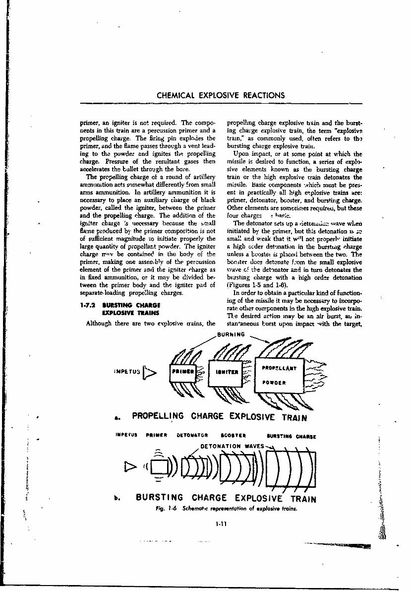
primer, an igniter is not required. The compo- propelling charge explosive tv.n and the burst-nents in this train are a percussion primer and a ing cha-:ge explosive train, the term "explosivepropelling cla-ge. The firing pin explodes the train," as commonly used, often refers to th,primer, and the flame passes through a vent lead- bursting charge explosive train.ing to the powder and ignites the propelling Upon impact, or at some point at which theclarge. Pressure of the resultant gases then missile is desired to function, a series of explo-accelerates the bullet through the bore. sive elements known as the bursting charge
The propelling charge of a round of artillery train or the high explosive train detonates theammmution acts somewhat differently from small missile. basic components which must be pres-arms ammunition. In artillery ammunition it is ent in practically all high e'plosive trains are:necessary to place an auxiliary charge of black primer, detonator, booster, and bursting charge.powder, called the igniter, between the primer Other elements are sometimes required, but theseand the propelling charge. The addition of the four chargcs -: 1a•ic.
* iguiter charge ýs necessary because the sall The detonator sets up a 'etoni•,i, .- ave wLenflame produced by the primer composition is not initiated by the primer, but this detonation is zof sufficient magnitude to irdtiate properly the smai! and weak that it w41l not properl" initiatelarge quantity of propellart powder. The igniter a high o:der detmnation in the burstiag chargecharge xr-v be contained in the body of the unless a boostet is placed betwveen the two. Theprimer, making one assembly of the percussion bcniter does detonate f.-om the small explosiveelement of the primer and the igniter ,harge as w"ave cf the detb)nator and in turn detonates thein fixed ammunition, or it may be divided be- bursting charge with a high order detonationtween the primer body and the igniter pad of (Figures 1-5 and 1-6).separate.loading propelling charges. In order to obtain a particular kind of function-
ing of the missile it may be necessary to incorpo-1-7.2 BUSLTING CHARGE rate other components in the high explosive train.
EXPLI, VE mAINS T.e desired action may be an air burst, an in-Although there are two explosive crains, the stan'aneous burst upon impact with the target,
BURNING
MPEU 11111191 " PROPELWLANET
POWD[R
£ . PROPELLING CHARGE EXPLOSIVE TRAIN
IMPIE'uS PRIMER 6ETONATGN $00STR "URSgIN6 C&ARSIE
DETONATION WAVES
b. BURSTING CHARGE EXPLOSIVE TRAINFig. 1-6 Sch~rnwhc repeesentation of explosive trains.
41-11

SOURCES OF ENERGY
or a delayed burst shortly after the p ojectih in the body near the booster charge. in thishas penetrated the targev. -IThe corponerts which manner the detonating wave is transmitted in-may be used to produce t' -se various actions staptly to the b:justing charge.are: primer, black powder delay pellet or train, The upper detonator is an assembly whichupper detonator, lower detonator, or some corn- contains the pzimer and detonator. The lowerbinatiun of these components. Regardless of th,• detonator is an assembly which contains dhearrangement of thz --omponents, the basic cha',n detonator a'd some booster explosive to leado f events must be provided, into the booster.
The action which causei La projectile to burst In order to permit penetration of the target byin the ai: may be obtained by placing a primer the projectile before bursting, a delay action is(which is fired when the projectile leaves the necessary. This is obtained by placing a primerweapor or when the bomb is dropped) and a and delay element ahead of th, detonator.black powder time crain iT, front of the bas.c In some cases this combination of primer andchain. The primer-ignites the time train rings, delay is inserted between an upper and lowerwhich burn for the length of time for which the detonator.fuze is set, and then in turn initiate the action trf A vai-adnn of the high explosive train is foundthe detonator, booster, and bursting charge. in chemical shells. In this train there is no laigeOther methods for accomplishing the same end bursting charge such as is found in high explo-result will bc di uss••ed under "Fuzes" later in sive projectiles, as it is often desirable to onlythe text. rupture the shell case and allow the chemical
To burst the projectile promptly upon impact conten's to escape, not to diffuse the chemicalwith the target, a superquick or instantaneous filler. The actual bursting of the case is accom-fuze action is necessary. Such action is usually plished by an enlarged booster, known as aobtained by placing an upper detonator in the burster charge, contained in a tube runring the
extirmme front of the fuze and a lower detonator leng'h of the shell along its axis.
REFERENCES
1 T. L. Davis, The Chemistry of Powder and 3 M. Meyer, The Science of Explosives, T. "Y.Explosives, John Wiley and Sons, Tnc., N. Y., Crowell Co., N. Y., 1943, Chapter 2.1q42, Chapter 1.
P. R. Frey, Chemisiry, Prentice-Hall, Inc., 4 Richardson and Scarlett, Brief College Chem-N. Y., 1952, Chapter -. istry, Henry Holt, N. Y., 1942, Paragraph 52.
1-12

i
CHAPTER 2
THE THEIRMOCHEMISTRY OF CHEMICAL EXPLOSIVES
2-1 CHEMICAL REACTIONS OF EXPLOSIVES
The ,levelopmevi of ianv and improved types For most common reactions, tables based. onof am'nunition requires a continuous program previous investigations permit rapid calcula-of wearch and development. Adoýion of an tion of energy changes. Products of an explosionexplcsive for a particular use is based upon remaining in a closed calorimetric bomb (aboth. proving ground and service tests. Before constant volume explosion) after cooling thethese tests, however, preliminary estimates of bomb back to room temperature are rarely thos'-the characteristics of the explosive should be present at the instant of maximum temperature
and pressure. Since only the final products maymade by theoretical calculations and compari- be analyzed conveniently, indirect or theoreticalsons with laboratory and smaller sc'2e experi- methods often are used to determine the maxi-mental tests. Such calculations are made using mum temperature and pressure values."the principles of thermochemistry. Some of the important characteristics of an
Thermocdlemistry is concerned with the explosive which car. be determined by suchchang•es M. "tIernal energy, principally as heat, t' YeoiAaJ a "omputatons and which are discussedin chemical reactions. An explosion consists of in this chapter are:a series of reactions, highly exothermic in their (a) Heat of explosion.summation, involving decomposition of the in- (b) Volume of pioducts of explosion.gredients and recombination to form #he prod- (c) Potential of the explosive.ucts of explosion. Energy changes in explosive (d) Maximum temperature of reaction.reactions are ca.culated either from known (e) Maximum pressure developed in a closedchemical laws or by analysis of the products. chamber.
4
2-2 REVIEW' OF BASIC DEFINITIONS AND CHEMICAL FUNDAMENTALS
An explanation of th,', chemical (stoichio- in metric units. Problem solutions are simplifiedmetric) terms used in the discussion follows, accordingly by using metric uaits in calculation h.The metric system of weights and measures is Iused in explosives calculatiois and all tabula- ard then, if desirable, by transforming the re-
"* ; ticas of values of factors and constants are given suits into engineering units.
2.1

L!
SOURCES OF ENERGY
2-2.1 GRAM MOISCULE it conctant volume is termed k, It is typically
Sgram molecule of a ccmpound is a precise arz, r than t, actually about 1.2-1.5. Its value isA~~~~~~ funtio ofecl the agoaonds.apesweight of that compound-, it is the gram-molecu- .unction of the gas.lar weight, or the weight in grams, numerically 2-2.5 SPECIFIC VOLUMEequal to its mole:lar weight. The molecA.Osaaweight of mercuiy fulminate., Hg(CNO,),, is The specific volume ci a gas is the vojume of284, and one gram molecule of this e':plosive is a tnit weight of a gas at 0*C and noinial at-2&4.6 vrams (see Table A-5, App-4ndix). This mo:;pheric presrure (103.33 kg/dM2 ).te irm is imsu a lly w r .itten g m to ol2 2 6 M O E U A W I
22 GUAM FOTEI~ULA WEIGHT2-M &W FaMUA4WEGHTThe molecular valume is th~e volume of a gramn
When the expls'si e is a mixture itea-i of a molecule of the gas at 00C and normal atmos-lcompound, the i•rrm gram formula weight is used phfric pressure.
"n lieu of •graw mnlecular weight. it indicates aweight ,n grams eqaal to the sum of the mokcu- 2-2.7 CO-VOLUMElar weights of as re.my molectae, of each in- ".'he •o-volume of a gas is defined as thegredient as appear in ti-e formula of the mixture, sm illet volume into which a unit weight ofThus, a gram. formula weight of b 3ock powder, the gas can be compressed. In this course for the
12) gS+ , or 10 grams. +i3lal32a ga.,eous products of explosion, the co-volume-- ', X i2)grsr g s.iwil be assumed to be 1/1g0s0- of the specificgrar, formula weight .if a mixture of TNT and wl easmdt eI10gariwforma weightra r~p d a y mi ture fofrTNT lan volurne. This is of course not precisely true, butasnuTAonium nitrate re~pr.sented by the formula li'eeorest.
CsH. (NO.)0CHs 4. 3NK,NOs is (227.1 + 3 itle eior results.
X 80) grams, or 467.1 grcaz. 2-.2,S SICIC GRAVITY
2-2.- SPECIFIC HEUT The speciSc gravity of an explosive is thera.tio of its weight to the weight of an equal
The specific beat of a substance is tie quantity volume of water at 40C.of heat required to produce a unit chan'ge initem-perature in a unit of mass of the substance. 2.2.9 DENSITY
Only small error results if the specific heat ofsolids is assumed to l:e constant through wide The density of an explosive may be expressedranges in temperature. provided ti-nperatures in grarm per cvbic centimeter. In the metricnot too near their melting or their dissociation :system, since one cubic centimeter of watertemperatures are approached. A similar assump- weighs une gram, tfie numerical ,expressions fortion may be made as to the specfic heats of density and specific grF y are the same. Inliquids, except in ranges close to their freezing, engineering 'units speci_,c gravity ard densityboiling, or dissociateon temperatures. The spe- are not identical values. The term load densitycific heats of gases vary with the temperature, refers to density (or specific gravity in cgs units)and the specific heat of any gas at constant of the explosive when loaded. This value is oftenpressure C•, is always greater than that at con- slightly larger tnan explosive density beforestant volume C, since in the former case the loading sinac explosives are sometimes cornwork of expansion is involved, pressed during loading.I2-2.4 MOLECULAR SPECIFIC HEAT 2.2.10 DENSITY OF LOADING
The molecular specific heat of a gas is the The density of loading, as used in calculatingquantity of heat necessary to raise the tempera- pressure in a closed cham.ber, is the ratio of theture of a gram molecule of the gas IC. It varies weight of the explosive chQ.rge to the v eight ofwith the temperature., and can be defined for the volume of water which would fill the totalconstant pressure or constant volume. The ratio chamber hi which the charge is to be burned.of the specific heat at constant pressure to that Note that this is not the same as load density.
2-2II . m • • . w m • ..... •... .• r.- m •
ITHERMOCHEMISTRY
2-2.11 CALORIE heat liberated or ab'orbed in any chemricalA calorie i.s the quantity of heat required to modification of a system depends solt.ly upon the
raise the temperature of one gram of water (one initial and final states of the system, provided
cubic centimeter) from 14 to 15"C. 'flits quan- the r.rsformation takes place at constant vol-
tit oi heat is sometimes call.A a small calorie. ume or at constant pressure. It is comp'•'telyindep-ndent of the intermediate transformations
2-2.12 KILOCALORIE und of the time required for the reac.tions.A kilocalorie is 1000 small ca!cries. In exrlo- From this it follows that the heat liberated in
sive technology a kilocalorie (kcal) is called also any transformation accompiished tirough suc-a large calorie and is abbreviated L.C. cess-ve reactions, is the algebraic mm of the
The mechanical equivalent of a large calorie heatr liberated or absorbed in the different ia-unit of Lhat, that is, the corresponding amount of actions. Consider the formation of the originalwork, is approximately 4270 kilogram-decimeters, explosive from its elements as an 'atermediateThis value is a conversion factor useful in reaction in the formation of the prr-iucts ofconverting heat energy to work enrrgy. In explosion. The net arm:ount of heat liberatedexplosive calculations, work is expressed in kg- during an explosion is the sum of Lhe heats ofdecimeters (kg-dm) because it is convenient, formation of th., prcducts of explosion, minur the
heat of formation of the original explosive. The
When a chemical U ON isformedeffect of this principle will be first obser/ed inWhen a chemical ompound is formed r:•m the calculation of the quantity of heat liberated
its constituents, the reaction may eith'er absorb at constant pressure.or give off heat. The quantity of heat absorbedor given oil durin; *ansformation is called the 2-2.15 HEAT OF REACTIONheat of formrion. The heats o" formations for fThe net heat difference between heats of kor-solids and gases found in ex-losive reactions mations of the r actants and producs in ahave been determined for a temperature of 150C chenina on termed t roactin.chenmical reaction is termed the beat of reaction.and atmospheric pressure, and aze •abulated in For oxidations this heat of reaction mey beunits of kilocalories per gram molecule. They termed heat of combustion. In explosive tech-are listedminthe-Appe-ndix of Part 1. Where a
linegative value is given, it indicates that heat is nology only materials which are exothermaic,
absorbed during the formation of the compound that is, have a heat of reactior, which causesnet liberation of heat, are of interest. Hence, in
• from its elements. Such a reaction is c,!led an this text hev's of reaction are virtue.lly all posi-endothermic reaction. The convention usuallyemployed in simple thermochemical calculations Sine r!s arbitrarily to take the hest contents of all ele-menits as zero in their standard states at a ditions of constant pressure or constant volume,thet asa zer inct o ca•ei st nd r statesse at ao n -I
temperutures. Since th,. heat of formation of a the heat of reaction cai be expressed at con-[ ompound is the net differne between the sta.rt pressure o:r at constant volume. As will beh n t mn o seen in Par. 2-4, the heat of reaction at constantS~heat content of the compound and that of its
elements, and since the latter are takeu as zero pressure is equivalent to a change in enthalpy
by convention, it follows that the heat content of the constituents of the reaction.
of a compound is equid to its heat of fomation 2.2.16 POTENTIAL OF AN EXPLOSIVEin ruch nonrigorous calculations.
The potential of an explosive is the total work2-2.14 ItlPl~tAC OPL ( •W ,-'UL •that can be performed by the gas resulting f"-
AND FINAL STATE its explosion, when expanded adiabatically fromThe principle of the. initial and final state may its original volume until its pressure is reduced to
be expressed as follows: The net quantity of atmospheric pressure and its temperatire to15'C. Thle poterztial is therefore the total quali-The standard state being defined as the stat= a 1.5tit ofhe vo ff at cstant vol whan
which the elei-aMts are found under natural or ambieu tity of heat given off at constant volume whenconditions. The standa~nt state temperature in this text expressed in equivalent work units and is ai-s taken as 15C. measure of the strength- of the explosive. 'A
2-3 41
SOURCES OF ENERGY
2-3 F.OT2N,'IAL
The poteatia., .ir the total work thet :s avail- f.,)rm a weight of exp'osive under adiabatic con-able as a result :.f ex--1 siGn under conditions of ditions is caiculoted and Lcetra'ted f.oot heat intoornstant voltime froir a given widght , an o,ý;valert. "'rnits, the potential or capacityexplosive, is a oeu_. !-nm in desc,-itiug the for work of-. weight of +he e.plosive results.effectiveness of an exFiosive. Hnce, if:
Using the principl i of the initial 4nd fuial Q., represents ýie total quantity c• neet givenstate, and heat of f )rmation tblias (resilting off by a g'ain molecale of explosiv, atfrcm experimental dana=), the heat released at ]VC and constant pressure (atmos-constan, pressu:e miy -be rad'•y calculated. pheric);
This quantity -A heat i4 dillerent horn the Q,., represents the total heac given off by aamount of useful hi~at actually released by an gram molecule of explosive at 15°C andexplosive in a gun chamber, sinte in a gur cen- constant volume;didons approaching constant volume not con- W represents th,: work energy expended instant pressure are met in p'actice. Thus, an pushing back the st•rrounding air in aneaplosion may occur under two general cn-- unconfned explosion and thus is not avail-ditions: the irst, unconfined, as in the open air abWe as at thewretim.! heat;where the -•ressuwe (atmospheric) is constant; E represents th,! mechanical equivalera ofthe second, coanflue.i, as in a closed chanmber heat (4z70 kilogram-decimeters per kio-where the volume is -tnstant. The same amoun'. calorie, or large calorie).of at energy L4. liberated in each .ase, but ,i Trhen, because of the conver.ion of energy totiie unconfined explosion a certain ,mount is work in the constant pressure case,used as work eirergy in pushing back the sur-rounding air, axid therefore is lost as hent. In a '. + W/Econfined explosion where the explosive volhunt is from which the value of Q., may be determined.small, howe -er (such as occurs in the powder Subsequently. the potential, EQ.,,, of a gram molchamber vf a firearm) pra,•tically al the heat of of an explosive r may be calculated. U.ing thisexplosion is ce.4served as useful energy. if the value, the poterntial for any other weight of ex-quantity of heat lilerated e Ponstat;t vcoitme plosive may be determined by simple proportion.
24 QUAWN;ITY OF HEAT LIBERATED AT, CONSTANT PRESSURE
If the eni.rgy change in a reaction is knowr C + O2 C0,
this change can be used as a basis for cal(.ulation (constaunt pr-asare)of work (au d pressure) effects. However, the + heat liberated (94.03 kiiocalories)absioiuie h,-:t c-ontents of explosive compounds There arc 94.03 kiloca-ories 'given off" by thisare difficu.t to calculate, so the qua.ntity of heat reaction, or A net gain of this amount of heatliberated ii any givez, reaction may be caivulatedonly from the ceactants' net change. in energy. energy ii the end product. C02, is cooled back
Such a technique is used in detei. vi ag heat of io the original room temperature (150C) of the
formation of explosive reactions. As r. further reactants. Looking at this change thermody-
simplifi:•ation in such calculations, the heat namicaly, if this C00 reaction is carried to
contents of the elements in their ,mcombined, comapleton in the atmorphere, i.e., at constarc
"standrd * or elemental state, are assumed to be pressure, the heat change is a change in enthalpy
zero. As a result of th-` mizurption, the tai f - e oot,- (--t"rdpy ; .. wilbechange irk heat of the reaction may be assumed recalled by the student that heat ciaonge ,f,to be th,, net c~hange of heat between the ex- a system at constant pressure is a change o-
plosive and its (nonelemental, or compound) en6 enthalpy. Enthalpy is deined as:pro6',ca. For example, in the equation H - U + PV (2-2)
2-4
u7
L
THERMOCHEMISTRY
or C+02 -(0 +941.38 kilocalorieCo. -CO+1/20% -67.Q4 kilocalories
(enthalpy) (internal energy)+ (energy in pressure-volume, terms of system) adding:
rathalpy is not heat. It has the dimensions of ý+%+Coi-M+C.+1/2 C.enetgy, but while both of its terms are "energy'teims it may riot represent wholly available 0-, cancelling C0 2 's on each side of the equation
energy. It is merely the sum of U (internal en- gives:ergy) and PV (pressure-volume energy). Substi- C-+ 1/2 (h -CO +MA.42 j.
tuting into (2-2) the value of U in the first law of This is the heat of formation per mol of carbonthermodynamics (conservation of energy law), monoxide formed.
.1el, Ii.
wUI i•: Using simtiar reasoning on equations describ-
Q U + W (2-3) ing the formation of simple products. and by(heat (internal .(work actually measuring the heat evolved, tabls for
energy) energy) energy) the heat of foimnaon (or enthalpy change) have
Lben lbeen compiled (sev Table A-5, in the Appen-llx).
U = Q -W Such heats of formation are for conditions of
and (2-2) becomes: constant presAsre and must be adjusted if con-
H = (Q - W) + PV stant volume conditions are to be met Thus,
or, differentiating, to calculate the quantity of heat liberated at
41H =Q - dW + PdV + VdP, constant pressure, the net heat difference be-tween the sums o the individual heats oi rtuc~on
wad if only the constant pressure case is consid- of the rnd idual mastbe do
ered, then, since dW - PdV, of the reactantz and tae produm must be de-
dti = dQ - PdV + PdV + VdP termined. For examn .e, the chemical reactionrepresenting the explosion of nitroglycerin, with
or, since VdP = 0, the total molecular weights and heats of forms-
dlt = dQ (2-4) tion of the explosive (assu-.ing that the products
Hence, under conditions of constant pressure, a of explosion will be as Inzated) will be:
change in heat energy is equivalent to a change CsH,(NO,), -- 3CO + 2.51120in enthalpy. Mol Wt 227.1 3(44) 2.5(18)
Since enthalpy decreases when heat is given H.F. (+85.3) 3(+94.39)
off or iost. heats of formation of exothermic Mol Wt +.5(8) .2532)
reactions are given negative signs in many en- H.F. 2.5(+57.8) (asumed 0)gineering texts. However, in this text in orderto simplify calculations (since only explosions This reaction can be expressed in words bywhich "give off" heat are of interest) for any saying that 1 gram molecule (or 227.1 grams) of
change wfhere heat is 'given off" the heat of nitroglycerin produces upon explosion 3 gram
formation will be given a positive sign: The ta-bles molecules (or 132 grams) of CO.; 2.5 gram
and illustrative examples in this book are so molecules (or 45 grams) af H.0 (gaseous); 1,5
arranged. The CO reaction previously described, gram molecules (or 42 grams) of N.; and .25would thus have heat of formation of -±-.03 �-ram molecule (or 8 grams) of 0.. The heats of
formation in large calories per grad molecule:; kcal. For many reactions it is very diflicu;t to=r_ ........ .froni tir elements and - are: nitroglycerin. 5.3 CO., 94.39. water (eza-sequently to deteine the heat of formation. eoas), 57.81. The nitrogen and molecular oxygenHence, for these r.tio'. the heat of formation have not combined with other elements in the
must be arrived at by indirect means such as reaction and hence do not give off heat. There-
algebraic additioa of simple combustion equa- fore, to calculate Q.,tions. For example, the heat ef formation of Q., P [3 (+94.39) + 2.5 (+57.8)]carbon monoxide is calculated as follows: - 1+85.3] - +342.4 L.0.
2-5
.......
which is the number of large calories evolverd by the gaseous -.r.t-. However, by considfring H 20
the explosion of 1 gram molecule (or 2227.1 -,!1 a gas in all phases of these calculations thegrams) of nitroglycer~n at constant pre_•.!;c. results theoretic.ally obtained are nearer to the
Observe that in calculating this quantity of actual observed results. Thus, H,2O wi'I be con-heet at constant pr,•!sure conditions, the assump- sidercd to exist as a gaseous product at 15*C intion wa3 made that the products of cornbustion calculations in this ieyt.had been redu-ed to atmospheric pressure and To convert the quantty of heat liberated perto a temperature of 15*C. Inol, to the heat which would be liberaied by
It should be noted that the heat of formation other weight of explosive such as a kilogram,of water has been taken as that for water in a the procelure is as follows:gaseous state. At 150C and atmospheric pressure Sincewater is liquid, but at the moment of maximum Ok =the total quantity of heat giv, off by apressure and temperature during explosioo and kthog qa t of heat giv n o nbat all working tcmperatures. the product,; 4 kilogram of exslorive at 15"C and con-explosion, includiag water, are gaseous. Ac- stant pressure (atmospheric);cordingly, in all thermochemical calculations in Then. using a simple piroportinn:this text, water is considered to exist as a gas.Acmually, to be consistent with the thermochem- QkV = 1tical reaction in the explosion of nitroglycerin, Q., mol wtusing heats of formation calculated at 15'C and700 mm pressure, the heat of formation of H2O Thas, for nitroglycernshould be considered for the liquid rather tlecn Ok = 342.4 (1000/227.1) = 1i57.7 kcali/kg
2-S VOLUME OF GAS LIBERATED
The law of Avogadro, verified experimentally, n,, = the number of molecular volumes of gas
states that equal volumes of all gases under the resulting from the explosion of one gramsame ctnditions of temperature and treasure molecule of explosive;contain the same number of molecules From nk = the number of mnoleculrc volumes result-this law it follows that the molecular volume cf ing from the explosion of one kilograza ofone gas is equal to the molecular volumn, of any explosive;other gas. The molecular volume of any gas at V., = the volume of gas in liters resultirng from0°C and under nermal atmospheric pressure is one gra'n molecule of the explosive at anyvery nearly 22.4 liters or 22.4 cubic decimeters. stated temperature;Thus, again considering the nitroglycerin re- Vk = the volume of gas in liters resulting fromaction, one kilogram, at any stated temperature.
CaH,(NO,);-, 3CO, + 2.5H,O + 1.5N. + .250, Then:
tie explcsion of one gram molecule of nitro- n. X 22.4 = V,, for 0*C and rernaml a mos-glycexin produces in the gaseous state: 3 gram pheric pressure; and ifnmolem-lus of CO.; 2.5 gram molecules of HO; nr. = 7.25 molecular volumes thea
1.5 gram molecules of N2, and .25 gram mole- V.. = 7.25 X 22.4 = 162.4 liters since onecule of O. Since a molecular volume is the molecular of any gas at W/C and atmos-volume of one gram molecule of gas, one gram pheric presmsre always equals 22.4 liters.molecule oi nitrogiycerin produces 3 + 2.5 ± = 7.25 X 1000/227.1 - 31.92 molecuLc-i1.5 + .25 = 7.25 molecular volumes of gas; and volumes.these molecular volumes at 0C and atmospheric Vt, = 162.4 X 1000/227.1 - 715.1 liters/kgpressre fo,.-. an actual volume of 7.25 X 22.4 =162.4 liters of gas. Hence, representative sym- The above value of V., = 182.4 liters is thebols can be assigned wherz: volume of gaseous products from', one g-am
F-6
"THERMOCHEMISTRY
mo.ec'ule of aitroglycerin at a".ospheric pres- tmrmperature.s"re and 0°C. To determine the value of V,, at Therefore, at 15"C the volure of gas -_rom15°C, wh,'h is the temperature for which the one grain molecvle of any explosive becomecheats of formation were calcula'ted and tabu-lated, use must be made of the law of Gay- 22.4 (1 + 15/73) Y n 23.83 X n,'.ussac for perfect gases. This law states "hq -, (2-5)
a coivztant pressure a perf,- ;- expaaOs 1/27 oroff Its volume a C-, for each degree of rise -n V \ (1 + 15/273)
2-6 EXTEZRNAL WORK PERSORMED IN EXPANSION4
Immediately upon explosion P the cp'en air, •2-6) becomesthe volume of an explosive substance is greatlyincrersed. If the quantity of heat consumed in W fydthe work of pushing back the surro,.ding air ,f," * pis calcuhted and added to Q,,,, the resultiag .(V - 1's) (2411quantity is; Q,, The external work perfon..din the expansion of the gas i-.ay be Jeterrnined in which V; represents the volume of the solidas follows: explosive and V. the vý!.,we of the gaseu;vLet products. Here V, is negligible cGmpared with
V 2 and may be disregarded. Therefore,
V fthe volume of any given weight of gas at W = p(2/rea pRels__re v an.i any temperature:
- the surface area of the envelope erelasinr From (2-5) and (U-8), W = 2,441.69 n.. (grg-d•i)the gas; and for the work of expansion of the ga.eous prod.
u = the travel of the surface s, as the gas rrt~m one gram mote".l- of we cxplosive atexpands. atmospheric pressure and 15°C. T71 !s derived
as follows:Th e work of exparsion is giver, bfo
F -•" = pdV '2-0) W (kg-dmN) = p'Y.,, 103.33
In thiL case p is the constant normal atmorpheiiX 3X 2363 X n. f-.ol)
pressure of 103.33 kilograms per square dev.- MODmeter, and for the work -erformed in expbtasion, 244 .69 n. (kg-tti) (2-9)
2-7 QUANTILTY OF HEAT LIBERATED AT CONSTANT VOLUME
The equivalent quantity of heat consumr1ed in Q., = Q., + 0.572 r., (2-1)expansion at 150C and under constant atmos-pheric pressure, but available in confined Xpl- For the nitroglycerin etion, for exampie:sion, is then Q., = 342.4 -r (0 572 x 7.25)
W1 P. - 2441.69 n,•/4270 346.5 L.O./gmot- 0.572 n. L.C. *kilocalo'ies) (2-10,, And
S ~itutQ this .value in ( ) 346.5 X 1000/227.1 1525.r, L.C./rskj
2-7
SOURCES OF ENERGY
2-8 POTENTIAL OR WORK
It has been shov.'n how the qtapty of heat one gramn mole,, utl oT in:troglycern,given off e1 constant volume by the -xplosicy, nýany substance, whose chemical reaction is known P,. = X,,, F = 346.5 X 4270may be calculated. These calculation.m are m ide = 1,479,5t,5 kg im/gm molor, a basis of cooling the products of explosicn Sim-iaily, the potential of one kilogram isto 15'C Practically, the detm'ýi!nation is ac-complished by the use of the Domb ':Alorimeter Ft = 346.5 X 4270 X 1000/227.1immersed -it a know, quantity ot water at a 6.514,993 kg.dm/kiiogramknown temperature.
Having de~ermined Q,,, the poiertiai of any Ptcndial represents the quantity of work that aweight of the explosive can now be found. For given weight of the explosive crn, do.
2-9 SUMMARY OF C-CULATIONS
The nitroglycerin reaction, in which ali prod- potentialucts are gaseous, will row be examined as a - Q_-x 4270resume of the foregoing work. gram molecule
P. = 3416 5 X 4270C3H (NO 3),--3CO, - 2.5H 20 + 1.5N 2 + "" . P,= 1,479,555 kg-.dmr/gm tool(a) The total heat given off per gram molecule
at enstant pressure: (hý The potentii I of one kilogram
Q., = 3(94.39) + 2.5(57.8) - 85.3 potential potential 1000=- 342.4 L.C.!gm mol = g X2
(b) The number of molecular volumes per gram kg grax molecule 227.1molecule: 1000
n- = 3 + 2.5 + 1.5 + 25 P, = 1,479,555 X= 7.25 mol--volumeigm mol 227 1
(e) The total heat liberated per gram molecule - 514,993 kg-dm/kg't constant volume: (i) The pote.,tial of one pound of nitroglycerin
Q., = Q., + 0.572 n., in foot-pounds:= 342.4 4- (0.572 X 7 potential kg-7in kg ft-lb= 346.5 L.C./grn mol p - x f--lb
(d) The volume of the gas produced per gram lb kg !b kg-dmmolecule at 0*C:
V. = 7.25 X( 22.4 Po. b = 67514.1'a93 X -- X 7233= 162.4 liters/gmin ol at 0*C 2 205
(e) The volume of gas produced per kilogram ft-lbat 0*C: P.. 1 = 2,137,095-
7., = 162.4 X 1000/227.1 lb= 715 1 liters/kg at 00 C Note that potential has been calculated for
(a The volume of gas p -5duced per kilogram assumed constant pressure adiabatic conditions.Vat (1 + 15/273) "lis does not mean to infer thr.t explosives
= 715.1 (1 + 15/273) liberate their energy only under constant pres-- 754.4 liters/kg at 15'C sure conditions. They do not. Actually, neithtr
(g) The potential (o. capacity for work) of on, the gun chamrber nor the rocket motor are con-gram molpcule at constant volume: stant pressure adiabatic systems. Rather the use
-2-8
4
THERMOCHEMISTRY
ot the potential concept gives an easy and con- pressure calculations, the fact that in the rocket"venient method of comparing two or more motor, combustion of the propellant occurs dur- 9explosives under similar assumed conditions. ing a flow process, alters the method in that the
For rocket propellants as well as for gun reaction occurs during motion of the reactantspropellants, potential is a measure of energy. and may not be complete before the productsFor rocket fuels haweer, the term -specific are ejected from the nozzle. Further, in a rocketimpulse" (defined as the pounds of thrust de- nozzle chamber the ambient pressure character-livered per pound of iuel per second) is in more istics influence chamber pressure and thereforecommon usage as a measure of performance. temperature.The magnitude of specific impulse is not only In a similar way, pressure in a rocket motor,a function of propellant characteristics, but also although calculated using the gas laws, is ais dependent upon the characteristics of the function of the rate of flow, nozzle character--svstem in which reaction occurs. Rocket pro- istics, and thermodynamic properties of the pro-pulsion will be discussed more fully in Part 2. pellent gas mixture, and thus not a simple,
Similarly, for rocket chamber temperature and constant volume system.
2-10 TEMPERATURE OF EXPLOSION
In the analysis of an explosive, in addition to the area beneath each curve represents heat;an evaluation of the potential which it will hence, for a given mixture, if the heat for eachdeliver, it is important to know to what maximum component can be determined between the limitstemperatures the heat liberated will raise the of temperature t. and t, then the heat of theproducts of explosion, since these products sub- mixture can be determined by calculation of theject the c'ontaining system to temperatures re- weighted sum of the heats of all products. Forlated to these heats. For example, gun tube specific heats measured at constant pressure, aserosion is related to thy temperature of explosion, in Figure 2-1, the derivation in total heat be-Explosion products are essentially a mixture of tween two temperature limits, to and t,, is arrivedgases, each of which has a unique specific heat. at either by rigorous integration, or by moreIt should be noted that our calculations thus simple approximation.far have assumed that reactions give off the For example, in Figure 2-1, the area beneathsame products each time an explosion takes the curve is:place.
Explosions do not always yield similar prod- f C,ucts. For example, when propellants are burned Q .in a rocket motor, combustion products con-sisting of varying sizes of molecules may be The expression for C,, as a function of tem-formed. Discussion of temperature ca!culations perature is not known. However, a close ap-in this text assume constancy of groups of prod- proximation may be attained by the series:ucts as shown. In such mixtures, the collectivespecific heat of the mixture is a weighted sumof the individual specific heats of the mixture For use as constants of each term in this series,components. values in Table 2-1 have been obtained for some
Also. since some component gases may have specific products of chemical explosives.different molecular configurations the specific Using this specific heat-temperature rolation-heat of each component may vary differently ship, a general equation may be drafted whichwith temperature. The curve for one such coin- can be solved for T,, the explosion temperature.ponent's specific heat variation, as a function of First, a general heat balance equation can betemperature is shown in Figure 2-1. Note that written as follows:
i" Copy
SOURCES OF ENERGY
II rrHcat available from explosive under con-
Heatlibertedby explosion- + beeatween tedC stant pressur- conditions between O0C and[[uedea l to Qta previosly-calbetweec u0lt d aIditionsbetween 15Cand Tc. and 15"C. T, on a mol basis. This is approximatelyLdtosbtenI5CadTj ln 5C equal to Q., ab prev iously calculated. (-4
(2-14)$ubstituting. keeping in mind that the specific sion temperature. The fact that the eo'.ation is
beat for all products is given by the expression: expressed as a cubic of temperature complicatesits solutinn, he c....;'r. aS aik approximate solutionCU . - a' + 0 7T + -Y'T ' (%-15) # . .C's'
weeC is the weighted sum tool specific heh" since the term i--TisaeatvysmUprsince thCer. T,3 is a relatively small per-
of all explosive products, and a', g', and -('are 3~tg fQ,,ti ev a einrdi
weighted sum constants of (2-13) for ain explosiveproducts. Then substitution in (2-14) gives: order to o'b•,n tin approximnate solution for T,
so that a trial-and-error technnique subsequentlyr fn le may be used to give a more atx~wate value for
C'.., di +"L C., dt '. Q., (2-1e T,. Once the cubic term is dropled the equation"le 0 becomes a quadzatic which can be solved using:
g and substituting values of (2-15) and -b z (2I19)(•16): ~T- -- -b--V -4c(2-19)2a
f W(a + ± + 7f +• .) , (2-17) where
Intejgrating and simplifying, 2
VT +' ý V ++ . .'(-8r'.+-2 T 22+- Tr3 Q., (2-18) c 1-000 Q., (since Q., is expressed in kile-
calories and the constants in Table 2-1 are
This'can be solved for T., the approximate explo- expreseed in units of cal/ 0 C mot)
Piroduct A
-" Product B
Molar specific Croduct-'h e a t a t c o n - -- T-- - -- --
stint pressure !(Cmp) I I
Area under curvebetween limits isin heat units.SI
to t1 5 Tx
Temperature (T)
Fig. 2.1 Cwimv -tho•wing variation of mol specic h"st with femporelur. for several g"los -w
*xpioive products.
2-10
THERMOCHEMISTRY
Subst-tuting these values into (2-184 yields: = [3(-3.405) + 2.5 (0.267) + 1.5 (0.4808)+ 0.25 (-1.017)]. • 0-6
+ + 20 (2-20) -. 000009051 -n -9.051 • 10-
This relationship gives an approximate T. which Q., = 342.4 motcan be used in a tial-and-error solution of (2-18)by trying teniprratures in the left side of (2-18) Hence, substituting these value into (2-20):until this side is identical in magnitude to Qm,of the right side of the equation. -(40.194) +V \/(49.194) + 1100 (.03684) (342.4)
For a specific explosive, since Q.. - Qp + T. COMM).572n,,, a similar equation for the approximate T, _• 31700Cvalue of T. expressed as a function of the con- Solving (2-18) by trial-and-error uiing this valuestant volume enthalpy change is: as the first trial temperature a value oi' T, -
-a + N/a'" + 2000fl' (Q., - .572n,,) 3240°C (0 T. = 3 513WK) is obtainad by succes-T. =- O sive approximation as shown in Table 2-2.
(2-21)
Note, that to be correct, a' and ft" are the TALE 2-1 HEAT CAPACITY (C,) CONSTANISweighted sum of all the product gases' a s and fl's FOp EXPLOSIVE PRODUCTS AT ONI ATMOS-(weighted for the mol amounts of the products PHERE PRESSURE EXPRESSED IN CALORIESliberated). Observe also that T, is a function only PER DEGREE CEITIGRADE PER GAMof a', A', and Q,, (or Q,,, and n,) and is inde- MOLECULEpendent of such other fact6rs as the density ofloading and the quantity of explosive. Pouct a
Consider a typical example: (X 10"-) (X 10-4)EXAMPLE: The temperature of the explosion IR2 6.947 -. '200 0.4808
of nitroglycerin is: 02 6.095 3.253 -1.017
CsH,(NOs)a - 3CO, + 2.5H1,0 N, 6.449 1.413 -0.0807+ 1.5H1, + .250, Hj( 7.219 2.374 0.267
a' , 3k.396) + 2.5 (7.219) + 1.5 (6.947) 6.342 1.836 -0.2801+ 0.25 (6.096) - +49.194- CO, 6.396 10.100 -3.405
[- 3(10.100) + 2.5 (2.372) + 1.5 (-0.200) 6.189 7.787 -0.728+ 0.25 (3.253)), 10-1 A4 3.38! 14.450 0.267Sfl' -[36.841]. 10--1 Si -3681-0- a ham Thevmo4mnanca for Chemiwta, Samuel
"+'0.03684 GLatone, Van NotXnmd, Inc.. N. Y., 1947
TABLE 2.2 TRIAL-AND-EKz, M.rT- ?OR OBTAINING APPROXIMATEIXPLOSICN AWKRATURE
Vp,'-e of3.684.10-' 9051.10-6 Value ofS~~~T, tried 49.191 T, + 3.684• 1-- T,2 9.5-.1- T.3 •-
2(1C) 3 (cal/vmt mol)(caloniea/gm nol)
3170 331.390 342,400
..3290 3492400 342,400
S~2-11
SOURCES OF ENERGY
It should be noted that the temperature of CHj(NO2)30NH4 -- 1.5CO, + 4C0explosion calculated above neglects heat lost to + 3H, + 2Nt + .5Cthe confining vessel, energy lost in expaflming Q., 1.6(94.3C) + 4(26.43) - 01%)the container, and the heat content of products - 169.3 L.C.between 150C and absolute zero.
i-10.1 TEMPERATURE WHEN SOUD onsidering car )n -,- a solid product with eUOconstant speýific heat of 1.98 calories per gram"POUT"AEFRE molecule, then
In those explosives which are. not entirelyconverted to gas, the heat absorbed by the solid a" 1.5 (6.396) + 4(6.342) +'3(6.947)products must be considered in determining the + 2(6.449) + .5(1.98) = +69.591temperature of explosion. Equation (2-18) was 1.5 (30 100) + 4 (1.&36)derived on the Lasis of all the products of explG- +3 = 0.201) (1.410 0) + 4 (1.836)sion being gaseous. Assume that in addition tothe gases there are x gram molecules of a solid which gives an approximate valce of T. ofproduct having a molecular specific heat of allthe products, and the value of a' for the mixture (-69591) - "V!•6 591 )+ 200(.02472)(169.3)of geser must be increased by a quantity rep- (t.0247n)resenting the heat content of the solid product.
As i.. the case of all gaseous products, (2-17) +46.5may be used to determine the temperature of T .02472 1879"C (or 2152"K)
explosion when solid products are forme.,4 itbeing necessary only to use a value of ee -ad K' Or by trial-and-error using (2-17) wher.for all the products, mboth solid and gaseous.
EXAMPIL: '11 explosior off ammonium, 69.591 T. + .02472 T.2 -4.95- 10- T.1picrte can be represented by the following = 169,300reaction: T', _ 17400C (20130K)
2-11 DETERMINATION OF PRESSURE IN A CONSTANT VOLUME CHAMBERf
The pressure developed by an explosive on considered. Its value determines the streng.4,being fired in a dosed chamber will now be and thus the thickness of the container .
2-11,11 t• 1E4•1AT11IO PV jr for standexrd eonditions at e* centi-From thermcdyr_=mic characteristics of all R - grade absoAute
porfact gases for any gas PV = n•T (where n isthe number of moo). For a unit weight of a P, V)
specific gs 273PV . RT (2-22) The ar.'trary "unit" amount for a givc• as
"Equation (2-22) is called the perfect specific (or mixture 4f gascs) used in this text is onegau equation and states tlhat the product of the kilogram. Thus defined, R is meaccured in kilo-ptessumre and volune oi a unit weight of one gram-decimetrs per degree kelvin for ouekio..wn Ttpec gas (or mixtire) varies directjy kilogram, and actually is the amoinmt of externalwith tho absolute tempzrature of .hat gps. Thus, work performed when a unit weight (kilogram)weittea Ior a i ga;s t., tjh gas contant., of gas (or mixture of gases), expands againstmust be a specqi and unique constant for 6.hat atmospheric pressure owing to a unit intcreae ofgas. Tlus, for a given gas, R becomes tempet-ature. R varies from gas to gas. Use. the
2-12
THERMOCHEMISTRY
phrase 'a unit weight of gas (or k miture of or,gaes)," sterns from Avogadro's law whi.hb states: RTAt identical temperature and pressure, equal P V (2-26)volumes of all gases contain the same number ofmolccules; and Wo Dalton's law which states:. Since the co-volume is the limiting volume be-If two or more different gases exist as a mixture yond which a unit weight of gas cannot bein a closed vessel, the total pressure exerted by compressed, the expression (v - a) is sometimesthe mixture on the walls of the vessels will be called the effective volume of the gas.equal to the sum of the individual pressures For powder gases the co-volume is generallyexerted by the gases making up the mixture. taken as 1/1000 of the specific volume of theTherefore, in accordance with these laws, the gas, that is, 1/100 of the volume of a kilogramassumption that each constituent of a mixture of of the gas at 00 C and atmospheric pressure, agases has trn same volume and temperature as kilogram being the weight on which all calcula-'the entire mittule, is a valid one. tions in the analysis are based. Thus, a becomes
For real gases (2-22.) is only approximatelycorrect and must be corrected for the behavior VU (2-27)of actual ga.es. which are not frictionless in their 1000behavior and are composed of particles of finite(though small) volume. 21I.2 PRESSURE IN A GUN PROPELLANT
In this text this correction is handled as a co- CHAMIJvolume correction in which the calculated ideal The calculations above provide a means ofvolume is reduced by a correction volume a. a determining the pressure in a closed chamberis defined as the smallest volume to which a unit where the explosive itself fills tl:e entire vnlumeweight of the gas can be compressed whatever A method of determining pressures developed inthe amount of pressure used. It represents the the chamber of a gun, capable of variations inspace occupied by the gas molecules when all charge size, will now be considered.the space between them is gone. Equation The density of loading, designated by A, has(2-22) then becomes: been defined as the ratio between the weight of
the explosive charge and the weight of waterP kv - a) = RT (2-24) which would fill the entire explosive chamber.
Such a correction, though accurate enough for The term should not be car.hised with the den-the purposes of this text, is a crude method of sity of the explosive, p.adjusting the ideal gas law for real gas behavior. gf the weight of exp wasive, r, is given in kilo-
: Van der Waals, Berthelot, or Virial coefficient gran• and the weight of water (W) to fill theequation techniques provide more accurate chamber is given in kilograms, thenmethods for corrections of this type. For ex-ample, Comer, in his book Inter-al Ballistics, A= or W (2-28)uses the relationship W A
Numerically, the chamber volume in cubic deci-B nC) meters is equal to the weight in kilograms of anPV nRT 1 + •+ " equal vokume of water, thus W represents not
only the weight of water to fill the chamber butwhere B and C are constants which are func- also (in metric units) the volume of the chain-tions of the gas under consideration. ber in liters (or cubic decimeters). Thus, substi-
For weights of gas (•,) greater than unity, tuting this value of W for V in (2-26):(2-22) becomes aRTaR= (2-29)
PV = coRT (2-25) 1 -aA
Equation '2-29) gives the expression for indi- -t5mum pressure to be expected in a chamber of
'P(V - oa) -" RT fixed volume.
2-13
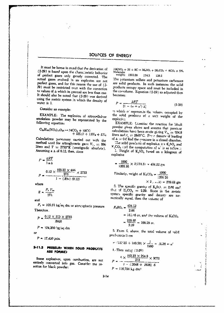
L
SOW'ICES OF ENERGY
It must be borne in mnnd that the derivation of 10KNOS + 3S + 8C -- 31KSO, + 2K.O, 4- 6CO, + 5N.(2-29) is based upon tbe charaz':eristic behavior Mo!ecughrof perfect gases only grossly corrected. The weights 1203.26 174.3 138.2actual gases evolved in an explcsion are not The potassium sulfate and potassium carbonateperfect gases, and for this reason the use of (2- are solid products. In such instances the solid29) must be restricted ,*ver,. with the correction products occupy space and must be included inthe co-volume. Equation (2-29) so adjusted thento values of a which in general are less than one. becomesoIt should also be noted that (2-291 was derived ecomes.using the metric system ;n which the density of ART (2-30)water is 1.
P 4- (a a.,,Consider an example: '\ which o" represeias thL. volurrt occupied byEXAMPLE: The explosioih of nitroeollulose 'he solid producxs of v un•it weight of thesmokeless powder may be represeated by the explofriv2.following equation: EXAMPLE: t~nsi' the reaction for bla1ck
powder given above and assurne that previeusCaoýXz(NO3 )x 10O -. 14COt + 10CO, calculations havo been made giAng Vo = 1NQ4.8+ 2110) + 13Hx + 5Nt lieters anw t,, z-- 2S. C. Fý"r - densitv of leadingCalculations pxevxousty ca-ried out with the of 4 -- 0= t find the r-csaure in a closed chamber.method u:md for nitroglycerin gave V, 896 The solid produr-ts of explosin x)a KSOSO andliters and T = 2733"K (centigrade absolute). '.CQ 5 -d the computation oS & s as fo!loia:Assuming a a of 0.12, then, cince :. Weight ef KSO4 laed on a kilogram of
explosiveS•4,T 1000 =434.S2
1203.26
0.12 27333 X IX 2733 -iLrilarly, weight of K1C1 -U0 lp 273% (012 .2M-26"(0.12) X 2..,..2) = 229.-8 grn
where 2. TVe speciEc gravity cf K2So: = 2-n and
- ° ol Sf M.,CO3 = 2.29. Since in *he metricI? [ - yster- specific graviry and derý-it are nu-2d tac teically eqtual, then the % olumc ofand
P. - 103.3T kgceq dni or atmcipheric pressure KtSO, 434,Z2Thetore. 2.66
0&ý2-35 en, and ,? volume of K0CO,2.12_ W,5 273. 100.9.cc
89---
2-29P- !24,200 ýg/ai dn 3. From 2, above. the total volume of -olid
or pr,-J)1ts in i,-nX
P 17,420•ia., f-(i3i 35 .- 00.29) ' - .2i;36
2-1.3 PuEMU~v WHM 3OUD PRODUCU I. -Then usl 12-29)10-3 XF5 0
X Y-3.3 X .3'24.8Some explosives, upon ,.ombusticoi, are not p _ 3 X 4 .8 9/273entirely "-nverted into gas. Corisier 4eme re. I - (.2048 + 2636) .6
actirmc for black powder: P - 138,794 kg,dmr'
2-14

THERMOCHEMISTRY
2.1 ",4 ACTUAL CHAN'IER PRESSURE not move. Actually, the projectile does movewhich increases the size of the closed chamber
This simplified me'thod of ores.;;:re determina- before the propellant is completely burnedtion gives the maxinmum press,ire that might be Now consider briefly the gene~ral case whereencountered in a weapon if the projectile did volume changes during burning.
2-12 DETERMINATION OF WORK IN A SYSTEM OFCHANGING VOLUME AND PRESSURE
The cak ulations thus far considered have been (b) Rate at which gases are dischargedfor systems such as artillery propellant cham- (area of throat of nozzle end discharge co-bers, in which it was assumed that tl-ý volume efficient).has remained corstant" during the progress of (c) Thermodynamic properties of the ex-the explosive reaction. For propulsion devices haust gases.such as rocket motors, the energy released dur- (d) Condktions oo e.*her side of, and shapeing the e.x'plosive chemical reaction is released of the exit section.into ,n unsealed chamber in which the pressureis not constant Nor is the system purely adia- It is repeat-d that in spite of these differencecbitic since hot gases are lost in the jet out the in use, however, the basic calculad-ons of po-n7,7le. In addition, the quantity of explosive tential, temperature, and pressure are applicabler.,jy be changing since the fuel is in motion dur- to rockets as well as n. guns. For rockets, aing,*ts rm:ction and some may be lost trough the steady state 'ow adiabatic condition must benozzle. F(,7 rocket motors, the amount of energy assLuned, and in addition, a solution of severalliberated per unit weight of explosive is only simmitantous 2quations (required as a result ofone variable affecting the changes in chamber differing erý.aust products) must be solved bypressure and ternpiorature. Also of importance in trial-and-error methods.rockets arc: A more detailed discussion of propulsion is
(a) Rate at which •he gases are produced. included later in the text.
REFERENCES
1 J. Corner, Internal Ballistics, Philosophical 5 Samr-el Classtone, Thermodynamict for"uLibrary, N.Y., 1951, Cha:ter II. Chernist, D. Van Nostrand Co., N.Y., 1947,S2 Durham, Thermodynimics, Prentice-Hall, Chapters 1, 111, and V.
k• ! N.Y., 1954, Chapter 11.N.Y. 195, Chpter11.6 Hausman and Stack, Physir4, Van Nositrand,S" ~~~3 P. R. Frey, C~ollege Chemisrtry, Prentice-Hal) amnnadSak hsr.,VnNsmt
P. CollegeN. Cf.,hrrd Ed., 1948, Paragraphs 137, 1"i9-4O,SN.Y., 1952, Chapter 8, Paragraphs M- 167-68, 181-3.S~through 9-10.
- !4 Samuel Glasstone, Th'e Elemrie"iti of Physical 7 J anes Kendall. SrradtAs CoP~ege Cheirr,• 3 Chemistry, D. Van Nostrand Co., .YD. Appletua, Century Co., N.Y., 193,
1940, Chapter 7.
2-15 s
CHAPTER 3
MILITARY EXPLOSIVE CHARACTERISTICS
3-1 INTRODUCTION
In Chapter 1 it was pointed out that explosive are termed low explosives and are used prin-compounds or mixtures decompose at differing cipally as propellants.rates. When this rate is sufficiently rapid tocause nearly instantaneous decomposition, the This chapter deals wth the physical propertyexplosion is called a detonation and the explosive and military requirements for each of theseis termed a high explosive. On the other hand, explosive classes. It should be noted that thecompounds or mixtures with lesser rates of de- characteristics of 1ob, explosives used as guncomposition, which burn beginning at thý sur. propellants and rocket prope'dants differ some-face of the explosive and progressing inwards, what, and therefore are discussed separately.
3-2 HIGH EXPLOSIVES
in all military applications of high explosives, conditions of storage. This requirement in am-the requirement has been to increase effects munition improvement has tended to the utiliza-such a. fragmenting poweT, blast, and fragment tion of the mere potent compounds such as BDXvelocity. This increase requires improvement and PETN. Their application to ammunitionof the two major characteristics, strength and may be corsidered the most important develop-brisance, without changing the uniformity of ment in the high explosives field during Worldwi •c-inonmng and ability to withstand adverse War II.
3-2.1 GREATER POTENTIAL a negative sign. Thus, an explosive having per-
There is a definite correlation between the fect bal.lce to yield carbon dioxide and waterpotential of an explosive and the degree to has zero balance; one lacking sufficient oxygenwhich the explosive has been oxidized. To ex- has a negative balance; and one containing excesspress the latter the term oxygen balance is oxygen has a positive balance. An oxygen bal-useful. Oxygen balance is defined as the ratio ance of -20% indicates that there is only(converted to a percentage) of oxygen surplu. 80 enough oxygen to fully oxidize the carbonor lack, to that amount required for complete and hydrogen present in the explosive. Thisconversion of the end products, carbon and means that other, not fully oxidized products,hydrogen, to carbon dioxide and water. A zero such a4 H., C, 00, and CH4, would be formedoxygen balance means that oxygen present cor- with less liberation of heat. The followingresponds exactly to the amount needed for simple reactions illustrate this reduction in beat.complete oxidation of all products. if there i% an 2C+02 -- 2C0 + 2(26.43) kcal (L.C.)excess of oxygen, this percentage over is usedand given a positive sipn. If there is a shortage whereas:
p of oxygen, the percentage short is use.d' and given 2C + 20 -. 20C2 + 2(94.39) kc.*i
3-1
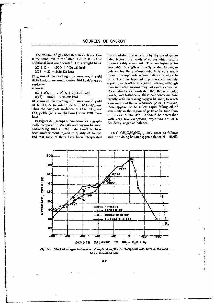
SOURCES OF ENERGY
The volume of gas liberateei in -achi reaction from bailistic mortar results by the use of calcu-i s the same, but in the latter ýase (17-96 L.C. (.f lated faciors, the family of curves which resultsadditional heat are liberated. On a weig' ht basis, is remnarkably consistent. The conclusio~n is in-
20 + 0, - 200 + 2(26.43) kcal escapable: Strength is directly related to oxygen2(12) + 32 -. 2(26.4) kcal balance for these comvoornds; It is at a maxi-
28 grams of the reacting substance would yieldl .. u in compounds Awhoe balance is close toyiel
26.43 kcal, or we would derive .944 kcal/grain of zero; The four types of explosives are roughlyexplosive. equal to each other at a given balance, although
whereas:their indicated maxima may not exactly coincide.
2CO yild (o9- a wegh bas4.3) some 28moe Inth car.ealof te~ tsol be noontrted that tesniiiy2(12 Fiur 232)-1 groups9 ofcm nsare gr ph- witer, few exsaceofthoese exmpionvs anrease
Icalycopaed n trngh ad xye~ baane. dcidely wtinegasine ba ygance. acorecConrasoideil that ralltheg davtanc ava d iale haveu a h er ~aepit Hwvrber!us&ed witouplte reidardtionqalt of s oure TCT, notX ma-eatasflw
kand thtcompaeofte haebeinrplednd in sotroiggha and oxygen- balance. ofiddl negtie b6ac
Coiiegtat a__teat _aaiabeavbeeH - -se wihu eadt qaiyo ou__ NCAV O1,ma ec sf~w
an 3htsm fte aebe nepltd adi oJighsa xgnblneo 6.%
10
TiYes AA4E T C. 4:
tog A- 9do sgnblneasrnt 1.xl~vs(oprdwt N)i h ed
P 5eck.xa=n% n P1eRT.
0 RUTCNTON
3-2
rI
MILITARY EXPLOSIVE CHARACTERISTICS
CALCULATION: Or there is a negative 02 balance of:
2CH3 C6 H2kNO 2)3 -. 12CO + 2CH, + H2 + 2N 2 -5.25825
Oxygen available:If a sample of TNT is exploded in a calorimeter
6 mols 01 bomb, containing in addition to the TNT aIn 12 mols of CO there are 1/2 (12) -='2 mols TNT sufficit.nt quantity of TNM (tetraniiromethane,
or 3 mols 02 axe available in TNT per mol an organic compound readily affording oxygenof TNT to the react.on) to male the oxcygen balance moreOxygen needed: nearly perFect, the explosive power is greatlyFor 14 C's a-e needed: 14 mols 02 increasod.
The relatiP.nship between oxygen balance andFor 10 H's are needed: 2 5 tols 02 potential IS a tool in the hands of the explosives
Total 02 needed: 16.5 mols 02 research worker. It is not the complete answer inor the search for stronger explosives. it is quite
16.5 tmols 02 conceivable that tuture work will show that--=8.25 are needed for complete2 mol TNT certain new arrangements of atoms may give
oxidation of TNT. enhanced performance beyond that which wouldbe expected frorn oxygen bdance or from calcu-
Hence 'there is a shortage of lated heats of explosion. Such increased perform-ance might result, for example, as a result of thoc
8.25 -. 3 = 5.25mols 02 arrangement as well as the constituency of themol TNT cxplosion.
3-3 HIGH EXPLOSIVE CLASSES
High explosives are divided into two classes Because of ihis inherent sensitivity they are useddistinguished according to their sensitivity. These only in primers and detonator mixtures. Second-classes are primary high explosives and second- ar high explosives are relatively insensitive toar socar ictigheposve and helat.T ely win suaitiv burary high explosives. Primary high explosives areextremely sensitive to shock, friction, and heat. sThey will not burn, but will detoiate if ignited. rather than detona~e when ignited in small un-Their strength and brisance are infer.',, but are confined quantities. They are used for boosterssufficient to detonate secondar,., hih explosives, and bursting charges.
S3-3.1 PRIMARY HIGH EXPLOSIVE the explosives are used. A moderately high ve-locity oi detc.nation is acceptable for primary
The following rn.quirmrnenis aie -.onsidered 'r high explosives liser, as booster or bursting
selecting an explosive substance as a primary charges.Shigh explosive: (c) Stability. Good stability is important hi
(a) Sensitivity. The explosive must be quite primary high explosives. Deterioration in storagesensitive, compatible with an acceptable degree may result in a low order of detonation for aof safety in manufacture, transportation, storage primer or detonator which would render an entireandi use. ammunition item ineffective.
(b) Velocity of detonation. The explosive (d) Hygroscopicity. Absorption of moisturemust attain maximum velocity of detonation in affects stability, sensitivity, and xelocity. Thus,a very short column since very small amounts of hygroscopicity is to be avoided, particularly in
3-3
,OURCES OF ENERGY
this class of sensitive explosives, of the explo-i-e, i.e., its ability to liberate nmuch
Since only small amounts of primary high energy, but also by the rate at which this energyexplosive are used, neither isb, cost of manu- is liberated. An -xplosive cani conceivably befaclx.re nor the availability ,f raw materials are strong but not ve:-y powerful, if it liberates energyimportant fr-tors Their melting poi its are not slowly. This is not usualty the case since, if
ca ,nsideration except as they affec storage detonation occurs, it provides for very rapidcharacteristics, and any tendency to react with liberation of energy.-metals can be readily avoided Strength is not (c) Sensitivity. The explosive must be safe toalways a factor for, in many cases. a long hot minufacture, transport, store, load, and use. Itflane, not strength, is the principal requirement. must withstand the force of setback when used ij
shells, and must be safe to jettison in the case of34.21 SRONDARY HiGH EXPLOSIV_ bombs. At the same time, it must be readily
The following requirements must be con- detonated by the action of a suitable explosivesidered in selecting an explosive substance as a train.secondary high explosive for use in components (d) Stability. Explo,,ives must be able to re-of ammunition. main unchanged after long periods of storage in
(a) Veiocity of detonation. A pound of coal any climate.has five times the energy of a pound of explosive. (e) Hygroscopicit). Absorption of moistureThus it is ensy to see that the rate with which must be low because of its effect on stability,,?Pera is m~ened .-.. portant to explosives. rensitivity, velocity, and strength.This is of specia! imFpoor--nr from a military (f) Meiting point. This is important pirticu-standpoLit since rilitary high explosives must larl, for those explosives which .re cast (melt)often be detoaated wathout tamping. They must loaded. The melting point should be betweendetornate rapid.y in order that they may attain a 80 and 100'C. If it is much higher than 100*C,maximum gas pressure before the gases are the explosive cannot be melted by low pressure
appreciably ,tissipated in the atmosphere. Foe steam and the use of other forms of heat forexample, in a 200G-pcand bomb detonated by a melting has beeii found to be more hazardous.nose fuzc, if the explosive detonates slowly, the (g) Reaction wiqth metals. The tendency toexpanding gases from the nose will start toward react with metals is undesirable but is not athe objective before the tail part has detonated. controlling factor in the selection of an explosive.If , 'ast-acting explosive is used, t)-e pressure Metal containers can now be- insulated from their>uiid-up is faster, and a larger amount of energy fillers w;th unreaectiv substances.will be delivered at one time. Therefore, the 'h) Availability and cost. The best explosiveiaster the explosive velocity the more violent the known could not be used if its raw materialsaction of the explosive mass. were not plentiful. For this eason, in the past,
(',. Strength and power, The total capacity many reserve explosives ,.--c*( as the Amatols,of an explosive is a function of the to* i' available became first-line explosives during wars: Cost isheat libervtcd during detonation. The ability of not critical in time of war. However, if otheran explosive to deliver this work energy is a factors were equal, it would be the decidingmeasure of its strengti:. Strength is of particular factor.importance when the explosive is confined, in=n underwater detonation, water "tamps" the 3-3.3 COMPARISON Or EXPLOSIV•S
gasea. and permits a high pressure to be thailt up The important characteristics of the morebefore the energy is dissipated throu'-hout a commorly used explosives may bep studied ongreat volume. An explosion in watei is thus fot, Table A-i in the Annex of Part 1. Explosives ;.xeand one-half times mare efftuctive at the point of listed in the order of their sensitivity and areexplosion than in air. If the explosive detonates compared to TNT, the characteristics of whichadequ±teoly, the more energy liberated, the are well known. The methods of conducting thegreater is its strength. teats, from which the table was eompiled, are
Power is determined not only 1-y the strength discussed in the Part I Annex.
MILITARY _^17:.",SIVE CHARACTERISTICS
3-4 PRIMARY HIGH EXPLOSIVES
Primary high explosives are used principalli agents. These compounds may be used as prim-an initiating agents in items of ammunition. As iig comnpositiuns which bum only if they aresuch, they are used in both priming compos~tions combined with less active ingredients such asind -s initial detonating agents. ground glass, ,ulfur, lead thiocyanate, or anti-
Priming ,ompositions are mixtures of com- mony sulfide. Mtrcury fulminate wi.l burn if itspounds or materials which by their chemical particles are only one crystal in thickness or whenand/or pihysical nature are very sensitive to desensitized by pressing to 25,000 psi or moreimpact or permission. When set off, they undergo (dead pressing).very rapid decompc::tie:. This decompositionis geo erally auto-combustion, ,nd not detonation. For initial detonating agents, azides, fulminate,When initiated, they give o•f hot gases and diazo, nitro, and nitroso compounds are oftenincandescent solid particles. Initial detonating used. These compounds will detonate. Manyagents likewise are sensitive to heat, friction, or compounds that have good! initiafting character-Impact, but detonate rather than burn when istics are too &ensitive or unstable to be used in
set off. arnmunition. Mosi initiating agents have a dis-Materials such as lead azide, mercury fulmi- tinctly lower velocity of detonation and brisance
nate, or lead styphnate ..re used as initiating than do the high explosives which they initiate.
5-4.1 MERCURY FWUINATE 145 to 2i5°C under normal conditions. How-
Merqury fulminate is the oldest primer and ever, it can be dead-pressed at 28,500 psi. In this
detonator. It is extremely sens~ive to shock, condition, hot gases will not penetrate into theI friction, a~d heat. It produeesw .• "teng. hot fic. interior portion of the explosive, and it willburn without detonating although it will detonatefrom a mercury fulminate priming charge.
Mercury fulminate is unstable. DectomposittfeG N - O-Hg - O-N begins after storage for 10 months at 50'C, orfor 3 years at 35°C after which it will not deto-
nate from impact or flame. After 17 months atFig. 3-2 Schemafic representation 50WC, the brisance decreases by over 50. This
of mercury fulminafe. characteristic makes it unsuitable for use in thetropics. The fact that -noisture will prevent func-tioning is usually immaterial as it is loaded intoa sealed container.
Because of its sensitiv:ty to flar?,w and I.-ercussion, Mercury fulminate is used in primer composi-it was for many years the most important material tions and detonators in the explosive train. Asused in primer composition and detonators. Since a primer, about 30% mercury fulminate is usutllv1930, it has been -eplacef in most military am- combined with potassium ohlorate, antimonymunition by lead azide. suifide, and quite often Aiti. :; ebrasive. The
Mercury fulminate is Q crystalline solid, white .*hlorate will oxidize the carbon in the compoundwhen pure. but in actual use usually gfayqsh- to cmbon dioxide, increa, ing the _completenessyellow. It discolors with deterior,>tibn. As of combusticn and the efficiency of the explo-meremy hilminate explodes before ii melts, it sive. An 80:20 (potassium chlorate, antimonyis prebs-lladed. sulfde) mixture is con-idered mbost effcient.
Its sensitivity iicreas.es with the crystal size Mercury is a sernistrategic ifhrrt iupply metaldue to increase in intermal stress. The presenc, - time of wai in the U.S. Mercury frlminat,, will-if any foreign material, such as sand, will in- not ,etonate cast TN?' and Explosive D (unlesscrease its sensitivity to friction. It detooates at ai, unsafe quantity is used).
X-S
II
SOURCES OF ENERGY
3-",2 LA k•120 fact that lead azi-& attains its maximum velocity
Lead izide ýs perhaps the most important of detonation in a shorter column th,.n .'r.uzprimeir-detonator explosive now in general use. ful.vinate. This permits a one-third reduction
Although less sensitive than mercury fulminate, in the amount of the detonator, and tbe use of a
;ead azide is extremely sensitive to shock, heat, longer column of tetryl booster.S and friction. Lead azide is one of the few The disadvantages of lead azide are its lack of
explosive-s that contain no oxygen. TThe azide sensitivity to stab action and fiame, and the fact
breaks down into lead and nitrogen with the that it d.es not produce an intense flame. Theevowtlon of much heat. first two objections are e'-sily eliminated but
mercury fu'minato is generally used whcr, flameN , N is desied, as with delays.
!!'N - Pb - N 11 3-4.3 LMD SIYPHNATI
N N Thir primaiy high explosive whose basicchemica! designation is lead trinitrorescorcinate,
Fig. 3-3 Lead aride. has *argely replaced mercury fulminate in prim-it is white to buff in color, but will become gray- ing compositions. It is very sensitive, stable, andbrown if exposed to light. Sincf, it explodes produces a strong flame. It has lEmited use as abetore m ei"ng it is pressed into it., contairer to detonator except as a sensitizing agent, althougha specific gravity of about 3 3. It cannot be dead- its power and velocity of detonation is good. Itpres-sed. It is transported azd stored in, or under cannot detonate TNT, tetryl, PETN, or RDX,water to -,educe danger of ignition. Its seusitivity It is used to lower the ignition temperature ofto impact depends on the crystal size. If the lead azide.largest dimension of each crystal is ovcr I milli- 0meter, it may detonate spontaneously. This isdue to an increase in cry-.talhin inter"na" st.esse3with increas.-td crystal size. It requires a heat of245 to 330'C to detonate and will always deto- P- N - Nbnate if ign;'ed. Lead azide is inferior in strength(40% of TNT) but this is not important to 'ts use
'is a primary expiosive. Lead azide is stable underthe most adTcise storage co,,Aitions. ;t willdetor,a.e with as mnich as 50% ioisture present. -0After hot storage, it becornme" slightly more sensi-,e to shock. It reacts with copper to form super-sensitive copper azides and, for this reason, is Ipressed into alurimmim contaners. NO2
i.,ead azide is used ba&, as a primer and a deto- fg 3-4 Leed 1rindroroscorcinat.nator. As it is not -ufflicientlh semsitive e&t!,er tostab action or fame to insure 100% operating Lead st.'phn. te v-.cs ih. color and may be aefficiency, about .30% lead azide is itsuwly u.e'.l light straw to red3-brown. It :s "-ress-foaded.with other ingredierts such as anitmor.y sulfid,, Lead styphnate ib very slightly less sei,sitive thenpotaý3:ium -zhioratc, and an abrasive. As a mercury fulminate. Its sensitivity is increaseddeton'Ator. i' is generally ,ensitized by the ad- considernbly after two months' storage at 7•'.diton of ,cd ,!yphnate to lower the ignition It rl,-tonates at temperatures from 200 to 300'°. Ittenperatwe. has about the same streogth aY ;ead az~de. Whvn
Leae .zide ovemT_'•mes most of the diLsadvan, properly primed, it detonatev with a bt-.anrzc ofL-ge3 of mercury. fulmip-ite. Aithough brisance 2-.4, coromareal with 20.3 for me'cur,'v fulminete.figure-, shov mercury fnItminate to b,1 slightiy Hon.ever, when ignited l,' flame its brsanc:, istupufror t. lead :-zide, the latter is a -nuch more only S.5 compared with I7.0 -for rnecury PiZni-ehicient dilonat-r. Thi; effcie,4"-v is due to the nate. It can be .ma-de ;roam nonstrategie mateuials.
3-S5
MILITARY EXPLOSIVE CHARACTERISTICS
3S4 SECONDARY HIGH EXPLOSIVES
This class of high explosives. though less sensi- dynamites. Chemically, these explosives are mosttive than primary high explosives, might be often aliphatic, aromatic, and heterocylic corn-[ tho-.ght of as noninitiating high explosives. They pounds which include nitro compounds, nitrates,are used as booster-,, bursting chargeý,, or demo- and nitramines. Of the many hundreds of corn-lition charges. They require initiaticr to deto- pounds which have secondary high explosivenation by a primary high explosive. Secondary charazteristics, only a few meet the tough sensi-high explosives may be divided into the follow- tivity, stability, brisance, hygroscopicity, anding types: single-compoo',d, b.na-r, plasti:s, and availability requirements.
3-5.1 TMKTYL appreciably better fragmentation of these shells
Tetryl (2, 4, 6-trinitrophenylmethylnitramine) than TNT. It is also more readily detonated, yet
is the standard booster explosive. It is also used in small caliber shells better withstands the forceas an ingredient in binary explosives and in deto- of setback in the weapon. It is also a componentnators and blasting caps, Its violence of detona- of tetr.iol (75P'25, tetryl/TNT), a demoliti6n.tion insures a high-order detonation. Brisance Tetryl, when pure and freshly prepared, istests show tetryl to have a very high shattering colorless but will yellow when exposed to light.power. It has brisance super½%r to picric acid or It melts at 129.450C 2•8°5F). Wnen heated,TNT, and its brisance is exceeded only by PETN tetryl first melts and then decomposes and deto-and somne of *be newer rhilitary explosives such nates. It is quite sensitive, can be detonated inas RDX. storage, and is very n•.~y•;•-'--'•.
3-5.2 ThiNITUOTOLUW3I (NT)[Cl 3. This secondary explosive, the most widely usedf bursting charge explosive, commonly knewn. as
"N- NOz TNT, is also a constituent of many e.plosives,such as amatol, pentolite, tetrytol, torpe c, ttitonal,
!uicjratol, cyclotol (Composition B), ausi e&datoL.NO2 It is known by such nicknames as tri'.:on, t-otyl,
OZN NOZ trilite, trinol, and tritolo.
TNT is relatively insensitive to blows or fric-tion. It I slow to detunate when ig'aited by aflame. If unconfiaed it burns slowly, withoutexplosion, giving off a he'.vy oily smoke. How-
/" ever, burning or rapid heating of large quantitiesI oZ" TNT, especially in closed vessels, may cause
violent detonation. TNT in crystalline form canbe detonated readily by a blasting cp, but whenft cast it is necessary to use a booster charge ofprezed tetryl or An explosive of Airnflar brIsance
Fig. 3-5 Tel., to insure complete detonation. Although i. dotsnot form senitive compounds with metals TNT
""letryl is suffir.ently insensitive whet, com- is readily acted upor, by untable Comioundspressed to be used safely as a bcoste: explosive, which are very s( aftive to heat and lzmtp-.tIt is used in te form of pressed cylir ers (called When stored in warm climates -zy during :rnhis e st.ndar bursting charge summer months, some ammuni-ion loaded with
S •-for MOmm anti 37-mra proje..-ti.les. It produces TNT may exude an oily brown liquid. 7U
SOURCES OF ENE~RGY
I exudate oozes out around the. threads ait the work. it is less sensitive to -,hock and friction
nt~e c th shl!awlmayfor apo.l o th tammni nitr ate and ony Nlgtly and, hsciiv tanpo
hoor Theexvdte i a mxtur: ofTNT nd TNl. Tthet ism geneyral cicirantdistsitsableN
24v toufricin bs not mappeiby bafdetonatedbyaracter.impact. Tetry is l sess as to e budser chanrTge ischgoeomica and inok theils pridese fmoliisturcks
0O 2 Neoul sNstieOopu,AmThseposiv 0'0 eis~o ( ammcanclmoixureo
Fig. 3-6 Tini~rotolceammonium nitrate and 7NT, and bywih hes hot, yitissufifet-l- fu to e si.ou enralc',rceit 0 astle TNT.
TNT i use as burtingch~-e ft high Ain lsatoli& ý10 V tooisirsof nish, anmedu nitratexplosiv a orid ton hn- TN It reembles wetonated bsugarewith mnionim nirate o fom 50 50 ori0/2acthe hot is lecoss plk]%tio exudei thanTT. sta is
shellsopi and bombs 6ihv aloner or moisted
asntol Fae NT Z isue n3-nmse n ressed i50t5 shellsi an ombs. A armontois-i-infrig. entatio nthandgrendes(N7. Oteniit usitrate fndor TNT bywign Whngoen torlgedot
TsesiofuTeT ase in busi~n g and -forp rt hig er A maoinoiir fIS mft*- irtepoieshell s annd bombbuts, eihe alon is mie nuW N tsed be, for -ieh adlrger shells.wtNT ar.nuse niorat d itioa fofr idges.1 oral rdma 80/20 Wie hoi !-eo lstic for : sinm tat starger)s
rmaols foriicakeTiNs- used othe str7-me n d o sh e~lls Aantd israsossed int largean bombs. mtliah infrges.ation chan gurposdes. te iia, sbtt o TNT is formedur t55rpedoesintof aIN large-shaped chand for pars, sm rall ighy Amnaipcae o xlsv .i h
least ~ i sesii ed torso'ick and frictin rofhmeitarcshpressed b lom k andtenclsed %nafbr n
tainer which makes it waterproof and protects it explosives Hence it is well suited as a bursting
from crumbling in handling, charge in armcor-p'ercing projectiles. it also
TNT is suitable for all types of blasting It is used as an ingredlient of picratol and! someproduces approximately the same oieffcd as the rNHlatseame weight of dyn~amite of 5M~ t-ý 6W. grade.It is manufactured from toluene and nitric a.-:id.In the prime state it is crystalline and nearly'white, but usually it resemrbles a light brown 0Z NNOsugar Pure TNT has a freezing point of about1776 F. Tn.e freezing point is more ieproducible h zthan the boiling point. Uniik -rame high exp~o-sives, TNT does not undergo partial decom-
position when melted and can be remelted andsolidified without significant change in its freecz-ing point.
3-5.3 TMTYTOL OTetrytol is a mixtare of 7 5T tetr% i and 2.5, TNT.NO
It has histher bris~ance t~ian TNT and is wore ef- Fig. 3-7 Amr-ronium picrcfcfectiv c in u vtting throt ug'r stteel and in er t; n 3-8~s~
)
MILITARY EXPLOSIVE CHARACTERISTICS
it is slighntly weaker in explosive strength than partially ove~coine by improved manufacturingTNT. NNhen heated it does not vielt but de- processes.composes. It is nonhyvgroscopic, in hutmid air, All nations are interested in devising means ofbut mnoisture has a niariketl effect oin its, bensitiv- utilizing RDX in a desensitized form, It ;s bei~ngity mn~ting it more sensitive. FA)IlosivC D is comb~linled with nitro hydrocarbions, wliieh willyellow to or-aige iii -olor and is not very reactive. permit cas- loading. or with waxes or o 's in
3-5.6 ROXpress loading. At present ti-e chief advangf~sof RDX are its tremendous power, good ,,tabit-
Thisexposie (> cv'timeh knetinir~iine it\', wid !he (act tbat it use:,. nonstrategic ra\%was patented in Gcrmnans in lVl9, asai medicine. -nici~. Isdsivnages ar it ih Ini"The British patented it as ain c\plosive iii 1920, m porint, its sens'tivit , and its lo higdwih re."ilt-
and termaed it Research Department FXplosi'.e. ii-i~ highr cost in manufacture.RDX. It achieved prominence dhiring l'oild (a ; D itrs CmoiinAi
WarII s a"suer ('plO~s . i. ecet :ear ~ the U.S. name for the PDX mixture w'-ich useshas Thecoine u'idt'! used as a base for many wax. as a Utsensitizer. The original mixitire,explosive mni.\ues of which Co.A-ipositihii 13 anct syich included hes.'ix, was not a particularlyComposition C, are v'xamples. Note that th,*s a gýood explosive as the wax dlid not enter into th'eheterocyclic, not at benzene ring c'ompouiid. In tietonation, and therefore, reduce-d thc, deton'a-addition to its true chlemical namne, it is a's-' thin s'elocity. In burning, it also took somie of the
called: ogen from the explosive, reducing its stfength.
Cvclonite or RDX- United States This mixture was used by the U.S. for pres- ioad-RDY (Research Dept- Explosive) -Great Britain ing 20-mm, 37-mim, and 40-mmn shells. It hasT4- 1E:tV heen used in foreign countries as a booster,flexogen (H)- Germany, bursting charge for grenades, and for armorTanoyaku- aan piercing shells.
The composition of prime interest at presentNO 2 is A-3. This uses a hvdrocanlxin wax as the de-
N sensitizer and gives exrellerat pedormance/ N compared to Composition A. It is used in 5-inch
H2I C C HZ naval shells and in highi explosive rounds.111) Cyclotol This was the mnost popular
RDX derivative in use du.ring World War 11. In0 2 N -N N-NO this country it is called Composition B, and con-
"ýN C Z' 2 sists of 60%f RDX and 40% TNT with 1% hydro-carbon wax added. Foreign nations use ether
ii percentages. 50:50 'ieing the mest popular, The
)4 38 Ccfc~nie~iy~ns-Italians call it tritrilitetr~rifnifmin- 'RDX). Composition B is cast-loaded, with a nc~urilig
temperature between S5 an~d 100'C and adeBOX is nim't-;factured svntlhekia~ll isivir sit" of 1.65. It is entirel'' stable but corrodes
formaldehyvde, arntronia, and, nitric acid. For- tt'.magnesiumn, colpper, and copper alloys verrna!-leh'ýde' and ý rmon: - a!'e condensed to formt sli'.?htlv Its main disadvantage is -ts senisitivity.hexarnethylenietetrami-e NNexrie hich is Table 3-1 compares it-, elfffciency with that ofnm-rated to RDX. Earl-er' ise of TtDX wa: pre- TNTvented 1)N the liarge methllv alcollO. :'etuirc-ments%, TAL - EPINC CQW SOS-;.nd the fact that elkven- poutids of nitric acid are OF TNT hHC; cycLeioreq'iir'ed to pi-dime one Pound of PD'. 1.- s ,d.ifrizuit to recover flth nitric acid , 'el pma?)U- _ ~ sv-- im;tafAi:ture, c.,;&. to the r-eact`o shwwr.hert'jnýu'frarma'dehvch'ý- ilrdl the! -Pern' -A1m'. The firSt TNT 'A__ 100 Io 100 100
of synifithe: rni-th~it aio- ~igol vmid t~h., I"od ('~i ~ l 2 2
SOURCES OF ENERGY
3 3.J7 PUIN Beco use PETN is so sensitive. pentolite is pre-
Penaeiythriteta-anitrate (or its acronym, pared by coating th- PEI N grains with TNT,
PETN) is restricted in its use because of its thus reducing the ovelall sensitivity. Pentolite is
sensitivity. It is one of the strcngest known not entirely stable in storage. The TNT, actingexplosives. being 6W5 stronger than TNT. Its as a solvent for PETN. accelerates the naturalprimary use originally was for boosters a~id tendelicy of the PETN to decompose.. Storage A
br-sting charges in small caliber ammunition; high temperatures may ?,cttially r:sult •a separa-
later it was -_sed very extensively as a TNT -.on of the two explosives.
diluent. Sipei& uses by the -i.S. are for the Pentolite is a very effective explosive and is
1upper detonator in some land mines and shells, 49e more e3ciex.t in shapeu charge tha_ TNT..and in primracord (velocity 6200 meters per Its high seneitivity precludes its use in ammu-
sec). nition, which should not detonate from shockimpact. Pentolite has been used for bursting6carges in small caliber shells (e.g., 20-mm);shaped charge ammunition of All tyTres (e g., Ar,
- -NO rifle grenade and bazooka); 9nd shaped demo-lition charges. Currenoy, Composition B is re-
02 N 0 1 !2 - CG CHz ONOz placLng pentolite for use in shaped charge
I ammunition.C HZ 0 , •Oz 3-5X4 HMX
.Cclotetramethylene tetrnnitrahmie, hike RDX,Fi.is a itrated cyclic (heterocyelic.• compound. As
( '.wotild lx- eectet fr-om its configuratior, andTbis .mnerial was patrntad ;u C.r, y ,A constituency, its properties are similar to those
"RN. Athmg~h it ha3 been used commeieiaaly of RDX, being nearly Njual in sensitivity, 91%.. e Atn37g, it cr eo use was mcdc of it for as brzsant, and 90' as powerful.
nftaz .-p,,y -atfl 5'?ced War Hi. In this N0Zcmatr.. ihterest was awakenee by repors thatthie (Cemanj had rep, LclJ TNT with a more Nbr;%int erplosive, beli-eve to, be PEEN• mixed
wX% T7,iT. in h-arges to be detuaated undri Hzc CHZwater. The e5avenesm ,A the new fillei wasJewnastrated in World War • w,•en t!-n Britishbaftleshtp "Royd Oak" w"s sauk wit', a tigle,torpcdo, Wlb used alone it is p..essed, as its NN -N N-NO0
ialting point of i38 to I41-C ;zevents casting.vI-.N is the !n-ost sensitive t the -,econdary
high explosives in gener._ use- It will eiways Hz.C Cl .daonr. frua the impict of z rifle bullet, and it
A•a lgniftm 1 epertur o 172 t:, 210°C. it
Sa whize to light-buff crystalfint. su'id, a,a therriita•y grade rntt he about W prLe b•!,-ause i• NOZis q ute ie wtie. o wticular)y t v Writ'y im p times.:_.
,efraiwmie (HMAX)."Ils has beei the nost widiet used PETN-
-ba" e-Viosie. It is &IO C4c -:! pento! (CQr- H.,;X, a hard. dense, white solid is a by-has, a'nd pentritol. 71w immm, k: 'ETN prodict ' the RDX manu'fciuriig cycle, As a
f;~ ~ Tfl (W39:•'), with w•z kded as a de.- reult 3f the ri~ture a'nd degrz.datior- cf hefxa-nw,. ethylmene.qtwine. HMX is D-oduced A ai
2-1
MILITARY EXPLOSIVE CHARACTERISTICS
small quartities If acetic .inlis'dride iq added lo lDvnati,,tes are all very sensitive to ;ho(-k,tne nitratio-' velt, yield is app-r.;\;n.ate-!v !) per- friction, andt heat, and will definitely (letonatcecent. from the impact of a bullet uoless they are de-
Since separation and vigorous purificat; )i or sensitized by addition oif inert i a- i-ials, whichsubsequently required, this explosive ;s quite in turn woulo' redluce explosix e power Whenexpensive and has not met gen~eral pvwrpose use froz'en thoey become extremely ~ ~i:edue toas a high explosive, but dres *nju\ increasing segreizdtioii of the nitroglycerin For the -.mespecial purpose use. revlso~j tht,, a~re less (ffic ient and maN give a low
3-5.1 DYNMTES, -rder 'letoiution Dynamites are approximately3-510 YNMITS -qu~al -,TNT in strength, but~ in velkwety and
Nobel gave, the name clynanitve to- ni~xture brisance tI'ev are inferior to TNT. h.-ving aof nitroglycýerin and ',jesegu-!_ T'ie ,troyigth of Yate of (detoniation of about Wk0 mneters per qec-dynamite was ind-.cated '.) tlie percentaLge of ond and! a brisance figure ol about T5 The) arenit'-Dglyceria in the mnixture Later it was dhis- cosdrdntbediue t". the hvti-roseopicity
covered th4! s~rcigvr di naniite-s c-oiilc he muade -ertain ing~reaients, and the tendenc% of nitro-111sng either sedium ker arnmonium nitr.att tn':,l a zl 'x' ria to scgieznt'! after prolo iged storagecombustible 1bi-de. (such as N%-(od lr-1ip, ne.'W The United Raote.% Engineer,; use 50% dyn,.mintehave heei c-alled geligaiitco nr actl~ve dope' '.'n , •oer demolitionis in this country. Tb7lc Br-tish uisemnites. Bj including nstro--elluilose wit]. "..cti-,e gz-h'gnitkes unzd(er t',c' namres of Nobells, 510:3 "0,
-im.e -ynt- the gelatin dvna.umit,?s were 2-The Cerinans u~sed gefil-piies ~rasaih£or-nulated. (J pj;4ToSeS. !.d½-ah n grena-de-s. 1)'. a-
Dv., ,mite!: bave been the ch-ef cormme>Ia! ot are o id or iita)P-.;rposes p~dubla!,ting explosive for v'ears. Thsev have little for tiher economny. O~so. ~hul. do nrit aui
miltay api~aionexeptfo dmolition pur- bos-ýr r~ni are very ser,-iN ix detormalio bpoz-es, 1becatise o; thei. sensitivity. Divrainites pron-eation Thecir ~andi!saL 'antnzes -re theiraie us:ialiy broiwnish ir, co'ar. In lorm they inay sensitix>,r% and lack of stability The 1british usebe either a powder n- -4 r'astic, pvttý-!Vk-e ;)n(, oflC pu..d of gelignite ti'. dr-onate bombs up toterial. Tsie two types in genefra, military use ~2M5 kilogramis an 1d~v pounos for bumbs overare 5-M nitrovgycerin dynamite and ýe~ignit!Ls 250 kilograms.
3-6 L!QUWD X'-GH CKXPCOSIVES
Periodically, there are reportr- of ne,.. liquid 1S-poie-tsmnzth SZevsitnvi'vSlifC]expr.)sives, muny ii~e mo~e powezrmii. Jhan Piweeaid10 10the Atandat ' highj explo-6ves. Such re:)irts l'mi 174 29be stud~ed --Arith caw. Fromn the previoz,. !i'-ick%%- MeL tnI ;28 -
sions concerning ticnatuire of -. p'.os;;ia, mdu 0- Tb';Iv n :cit dninfe7l1tpeexample of nitroglycerin wd.even witim V011) -.tx ee diyeidnitr-e 170 127luplete oxidptior, is only &';T stronger tharn TNT, k . tO1it wuuld not b~en -;rv orchablc tnat th-,> fivgure 15 10~COldl !;: c;:-eedesi b; -cr-' muvi; unless nuiclear 127
The f>co)owit.g is a list of Ixpi iquid 1ghu glCe.\Tlosives. The are ý.oipnlrf-d with picric acid n;~ ~ i ~ar 00in strenj, ik and sensiti,ýy.Iilii "d omplii ia-
-4
3-11
SOURCES OF ENERGY
Most of Cie presently proposed liquid high ex, stronger than staiidard expiosives, this advantage
plosives are too sensitive for genera! military use. often is offsct by low density. Since liquid highSme are unstable tn storage. Ot:,err, such as explosives present man-: problems and few ad-
'anite, must have their components in Eeparate vantagos much d&velopment re oains tv be donei crap tmntswith th iigtaking place just
cop tments whthe mixing t g j upon them before they become g-.nerally useful,before detonation. .orne, such as liquid oxygen, except possib!y to circvmvet,' material shiuages.must be used shortly after manufacture or theyevaporate. If high vapor pressure liquids are Howevcr, if furht research yieled a stable,
sealed in a thin-walled container, the evatora- high enc,{y, expbsive, temperature insemitive
tdon ard condensation can "upture 'o. %'clapse liquid, it would be -)f great interest o- a hIghthe container. While sorne liquid explosives are eyplomiJe.
3-7 M2IAL-HIGK EXPLOSWIE MiXTUAKS
In recent years the effee. of the addition of underwater, ant undefgrzur, exp'o'-;cn. HBX
metals such as boron, zinc, beryllium, Mithium, (-C-% Comp B/'.iZ TNT/% 11, A55 waAes, ,ilAo-
silicon, magnesium, and aluminum to explosives iml!ulose, lecithlr. has .-ecn develope. ;o fill thehas beeu studied extenmiively, bt-c-ause of the ex- nez-d for an a~uuhiized explosive vpith hghi re-cellent resuits predicted by theoretical thermo- sista:ac, v, mnpac•. As idiid&ci't• previously itdynamic computations. These predictions proved achrevs ths? by tfVc addition of w'ax ýo tie comn-inadequate, in that reactions were not as ex- positionpected and the metal was wot oridized ap- Tv dlus_.!e ]ow the a.uwa;nwn .an ki.ase
preciAbly in the detonation reaction. Iligh the !,ant eff"t f an ,explo•ý.w colsider the ,tlo-detonation rates were not observed; in fact. rater nadov of T-epex, Toepex is coirnered (4 405were lowmeed and brisance characteristics re- TI'NT, 42% B11X aad 16' ý,wdered a)umintmi.
duced. Surprisingly enough, bowe--er. it was (Dro-.etions -nay vary siig'ndIy frim th:s gere.,a?found that in the case of aluminum Zhat the oxi- fcrmuladr-n.) Whe' iiure TNT or RDX reae,.dation of the aluminum did occur after dctons- one of the prodicts of Yhe "xpl,)sion is C02, ac-!im was comnplete, and that .the energy so released coriJig tv ýhe f9ol:ing therm'Ahemicai x-.c-mtributed -rarkedly to the I",ver and bWst ef- aw~i-n.fects oN the aiumiiued products. The nature o5the expanding flame-gas s-urface provided amechanisin by which external oxyg-'n reached Powderel :u-amirmnt at thc temtnpturs p-evafl-
r'ie aluminum- The oxygen thus utilized, effec- ing in the :xplc-"oir ;s & mete p ,worful rodu~cin
tiveiv increased the nerformaace of the filler P.;e.t than e•-r'ou As , result, ir.sred of C"Oweight of the compo-_ent Ex '•pig products being fcfrmed, thb proewits are CO azi A1•0 3,haie beet observed to occupy about !hirm times a9 cordbi=:ý wo this ceaaion:-he volumne that would be preincted on tev as- C + 20 + 2A] - CO -J .4X .43rL.c.niaon that the expandIng p.'ducts merely. 380.49 L.C_ + 4'•5.92 !X.
puzi the sta-cunding atmasphere ahead of them.This disccverv led to the dev-•durment of severan The weight of the reactants in ktl frin i-1-
=taaoble •alm n materials fr tmb filling. stance is 12 + 32 -= -A. lp the stco,.d za-, thee g. M i-'•i. Tor-'ex. Trit N 3al . PX. etc. 't was weight of tde ractarts is 12 -4- 2(13 ) -- 2(28..qy)
found aft.e consderable -,-sting that alurmnized 129.94. Tr,-e heat lihersted ;i 64e fL-st cr._% i,_expkaives .ias sign ca;,dy greiter blast effects,r dazmxS rastit thn their uorz.iminiz cou- 94.39 143 LP per gia
tersrt. Prarticulariv strong effects eesuited from 4t
3-12i

MILITARY EXPLOSIVE CHARACVERISTICS
The heat liberated in thc se',=d case is: safety or corrosion problems, nor should it re-quire~ eacessively large quantifties of strategic raw
3.2 L.C. per gram materials. Of course, no explosive which would129.94 require an imported raw material would be con-
rhus, the reaoin involving aluminum is about sidered. The considerations have led to an ex-tensive cx imination of the field of synthetics for
i5O% ir.arc efficient as a heat producing rato, use as -avi materials in military expinsives. Thewhile~~~ it h aetm n qa oueo a development of improved manufacturing tech-
is evolved. In addition tlhe aluminurp is oxidh2ed niques to obtain greater yield, safety, and moreby the oxygexi in the air, which ir. effect allows -table ex.oie sacninigpolm o
Cie xplive-ootine oxyen o beu~e mo e ezample, Tetryl of acceptably good quality cane~e~ively.be produced fromi dirnethylaniline by a two-
Composition B certssts %A a mixture of 60% stasge, continuous process. Current research isRDX rzte 40% TNT Aý comparison between Tor- being directed so as to determine whetherpea And Cr'inp(Altion B shows that Torpex pro- equall) goad results can be obtained with aSluces an area of blast damnage about 30% greater ssvgle-stage, continuous proce-.s -which would ap-thin. t~he same volume of Composition B. pear to offler advantages writh respect to design
and uperation of equipment and savings in nianu-Tne ed tltion of mectals to low explosives pro- iacturing costs. It would also be safey since less
vick; emparzble hicreaaes iti propellant per- Tetrvl would be in process at any time.formanare. bit since slower rates of energy Efforts are, mocstantly 'being made to improveAberation are dc~iirable in a propellant, the en- the storage life of explosives. In World War Iergy per vinit weigl~t ;irprovement *s generally a considerable quantity of TNA (teltranitroani-lower, arn thsus, this tzh im;ehs not enjoyed line) was manufactured as an experimental shellWide a~c-cptance far propellants. filler. After being stored for severai years it un-
derwent an autocatalytic reaction wit h the fox-
3-7.?kXPLSM11 i"M0AM-ANination of highly sensitive compounds which ledZV%.MDL-1kARMA!JACWN to explosions in storage. TNA therefo-re is not
used today by the United States as a shell filler.Since funds ý,ir U-n-' of peaPce) are nct avail- This type of failure points out that it sometimes
ab~le to naiiitair. 11i~rgt ettabuighments for the takes ten or fifteen years to uncover stability flawsprrnar=Ftion of exp-isves. k is '444l desiibv~s -n an otherwise acceptable explosive. Am-munitionthat any standard military explosive. b.- apa1~e mniit be capable of long storage, sometimes asof being rnade in er~stiný '_hervuri- p~tnt la:;--. lon~g 9s twenty-five years, with no loss in ballisticties. Preparation should act introdiuc. extreme efficiency or safetty.
348 LOW ED'LON-wbf OR PROPIDLANTS
VTee second f amily of explisivos, called pro- charge is defined as ra powder charge uszad in a,JNlantý or low explosives, diff'wis fror,ý high cx- weapon which when ignited produc,:s large
slower. They burn rathbr than dmne.ouztthebarrel.Although for several!,ndredThe~~Ž ienerhal proeir ti fdcmoii~ s 'oes of. ga kp3vs whichya. lc podrwapils oc the ol prajcticale
13 A
SOURCES OF ENERGY
compound.) All explosives currently in use as as well as freedom from changes in chemicalgun propellants have a nitrocellulose base and composition.are (ommonly known as "smokeless powders." 3-4.4 RESIDUE"Tllese substances are not powders iii the truesense of the word not are they smokeless. Rather 71he exploded propellant should leave little orthey arc mn.aufacured as flakes, strips, pellets, no residue. Unexploded powder and una.,,Jdir.-d
It spb,!eres. or cylinders. The last type of grain is residue will corrode g'm bar, .Is, create s-.;oke,by far the most common, especially in this coun- and reduce efficiency.try. Continuous effort has been expended to de- ,-8. MANUFACTURES sign a smokeless, flashiess pow~tl, tiowever, The propellant should be easy to produce inas will be explained later, the complete absenceof snr,,ke or flash can b)e accormpliied only by quantity from plentiful raw materials,
accepting other unfaverable characteristics. 3-8.6 EROSIVE ACTIONThe qualities desirable in a good gun propel- The burning temperature should be kept atI lant will now be considered. a minimum to prevent erosion of the gun barrel.
3-4.1 CONTROLLED BUIRNING 3-8.7 FLASH
Any goxd propellan•t should produce a large The explosive gases mus, be as cool as possiblevolu.ne of hot gas and should burn at a controlled to prevent muzzle flash which will indicate the
rate. Guns are designed to withstand a naxi- position of a gun fired at night.mum gas pressure which occurs when the pro- 3-4 8 DETONATIONjectile has moved only a short aistance in the The propellant •Ihoutd be incapable of detona-bore. It is desirable for the propellant to attain tion as this will burst the barrel of the gun. Thisthis maximum gas pressure by a gradual and pro- implies no tendency fo• the grains to break upgressive rise in pressure. Control of this pressure under stress of firing.lies in the composition of the powder, the formor shape of the individual grains, and the dimen- 3".9 SMOKEfion: of any particular form of grain. Granula- The explosion should be smokeless, or the posi-tion determines the area of the burning stirface tion of a gun fired during the day will be revealed.of the grain. This, in turn, partly controls the Whether ammunition upon firing is flashless,rate of combustion and pressure. smokeless, or both, depends upon the weapons ir,3-8.2 SENSITIV!•tf which used, the type of ignition used, weapon
wear, the temperature of the tube of the weapon,The prcpellant should be readily ignited but as well as the quantity and design of the pro-
safe to manufature, transport, load, and store. pellant powder. "Mlasbless" and "smokeless" areIt should not burn or detonate under the shock relative terms and have been defined as follows:of being struck by a nonexplosive bullet or a flashless ammunition does not flash more thanshell fragment. 5% of the time in weapons of average life under
3-9.3 STABILITY standard conditions; smokeless ammunition pro-duces less than half the amount of smoke pro-
The propl Hant must be able to withstand long duced by ammunition not so designated. Astorage under all climatic conditions withcut complete round having both these characteris-deterioratin. This means lack of hygroscopicity tics is designated "flashless-smokeless."
3-9 BLACK POWDER
Black powder is mawifactur.ut in small shiny mate mechanical mixture. The charge is pressedblack grains. TLe ingredients are usually finely into a cake and pressed or extruded to the de-pulveri.ed ptassiuni or sodium nitrate, charcoal, sired grain size and shape. The grains are glazedand %u:lfur • :,h are incorporated into an inti- with graphite to prevent caking and accumula-
3-14
r
MILITARY EXPLOSIVE CHARACTERISTICS
tion of static electricity. The potassiurv or sodium to heat and friction, and therefore, must benitrate (about 75%) acts as an oddizing agent, handled very cATefully. It is hygroscopic whichwhile charcoal (about 15%), ant4 sulfur (about re,,uires that sealing precautions be taken to re-10%) are combustibles. Suffur also lowers the tain stability. Its strength is relatively low andignition temperature of the mixture from M0 the large amount of solid residue which it leavesto 300'C. The sulfur ignites first and communi- makes smoke reduction difficult. Flash redue-cates the flame throughout the mass. Sulfur has tion is also Z problem with black powder.colloidal qualities and fills the spaces between The manufacturing proTess is both easy andother components. It also acts as a catalyst and cheap. The required raw materials are plentiful.rediuce the solid residue. Fotassium nitrate is An advantage for certain uses is that biack pow-expensive but only slightly hygroscopie, so it is der, in small quantities (such as those used inused in fuze powders, wl e sodium nitrate, be- military applications), does not detonate.ing cheap but very hygroscopic, is used in blanks Black powder, in its several grades, is stilland spotting charges., used for the following military purposes:
Black powder is no longer considered suitableas a propellant because of its many objection- (a) Ignites in artillery shell.able features and because of the development of (b) Delay elements in fuzes.newer powders in which the undesirable quali- (c) Saluting and blank charges.ties have been overcome or improved. It is (d) Spotting charges for practice ammunition.difficilt to control accurately the burning speed (e) Safety fuse (burning rate, 1 ft in 30-40of black powder., Consequently, the range of a seconds).projectile propelled by it may vary. Blac k pow- () Quickmatch (burnirg rate, 9-120 ft perder is too easily ignited, being extremely sensitive second).
3-10 SM/,KEL.SS POWDERS
Smokeless powders are forms of nitroceiiuiose how size oi grain varies Ior iU,6 var;usexplosives with various organic and inorganic of gun. The grains for a cal. .30 cartridge areadditives and are used as propellants. They may 0.(32 inches in diameter and 0.085 inches long,be divided by compc'lition into classes of which while those for a 16-inch round are 0.947 inchestwo, the single-base and double-base, are the in diameter and 2-7/16 inches long. The per-most common. Both classes are manufactured forations shown in Figure 3-11 are for the pur-
in quantity in a variety of shapes including flakes, pose of controlling the rate oi gas liberation asstrips, sheets, pellets, or perforated cylindrical well as burning time. The single perforatedgiains (Figure' 11). The cylindrical grains are grain is used in small arms, while those. withmade in various diameters and lengths depend- seven perforations are used in large calibering on the size of the gun. Figure 3-12 shows weapons.
3.10.1 MJNtUNG TIM th-e web, the longer the burning time (Figure3-13).
The burning time caa >- controlled by the fot- (c) The quickness or rate of burning of thelowing means: powder.
(a) The size and shape of the grains including (d) The percentages -f volatile wawerials,the number of perortinert materials, and moisture present A 1%tFchange in volatiles in a low volatile contert pro-
(b) The web thickness or amount of ',offa pellant may caune as much as a 10% chanpe inpowder between burning surfaces; the thicker burning -ate.
3-15
?:':--• ISOURCES OF ENERGY .
00.,-AIL. 511EET STRIF" COr'4
? 62
nLLET SINGLE PERFORATED MULTI-PERFORIATED Ri)SE',TEFig. 3-11 Typical shapes of powder grains.
16-IN. ,-IN. 2NN '55M- i0- WC
$-IN.. PYRO -1 0
Fig. 3-12 Sire. of some typical grains.
WEB SLIVRS
000 ,, IA- UNBURNED GRAIN I-BURNING
Fig. 3-13 Web thickness and route of burning progress through a 0:progressively burning grain.
3-16
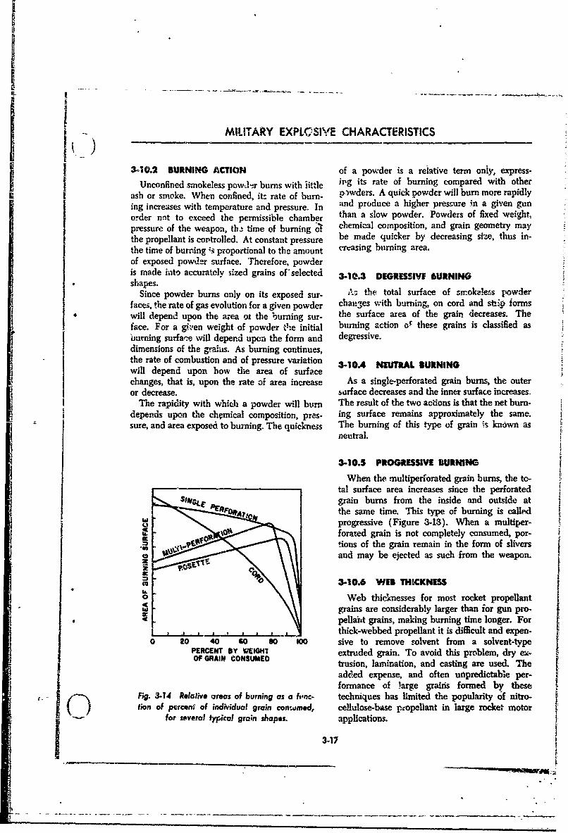
M IA MILITARY EXPLcSIVE CHARACTERISTICS
3-10.2 BURNING ACTION of a powder is a relative term only, express-I Unconfined smokeless powvd•r burns with jittle hrg its rate of burning compared with otherU nconfined~~ sm k l soowfi u n w ith itl wd r .A q ck p de w llb n m or her pi l
ash or smoke. When confined, it- rate of burn- nwdepr. A quick powder will burn more rapidlying increases with temperature and pressure. In and produce a higher pressure in a given gunorder nnt to exceed the vermissible chamber than a slow powder. Powders of fixed weight,tpressure of the weapon, th time of burning ol chemical composition, and grain geometry maythe propellant is coptrolled. At constant pressure be made quicker by decreasing size, thus in-the time of burning 3 proportional to the amount creasing burning area.of exposed powder surface. Therefore, powderis made into accurately sized grains of'selected 3-10.3 DEGRESSIVEF AURNINGshapes.
Since powder burns only on its exposed sur- A• the total surface of smokeless powderfaces, the rate of gas evolution for a given powder chanmxes with burning, on cord and sti~p formswill depend upon the area ot the burning sur- the surface area of the grain decreases. Theface. For a given weight of powder the initial burning action oF these grains is classifed asburning surface will depend upon the form and degressive.dimensions of the gra.iis. As burning continues,the rate of combustion and of pressure variation 3-10.4 NE)TRAL BURNINGwill depend upon how the area of surfacechanges, that is, upon the rate of area increase As a single-perforated grain burns, the outeror decrease. sarface decreases and the inner surface increases.
The rapidity with whic- a powder will burn The result of the two actions is that the net burn-depends upon the chemical composition, pres- ing surface remains approximately the same.sure, and area exposed to burning. The quickness The burning of this type of grain is known as
neutral.
3-10.5 PROGRESSIVE RURMING
When the -nultiperforated grain burns, the to-tal surface area increases since the perforatedgrain burns from the inside and outside atthe same time. This type of burning is calledprogressive (Figure 3-13). When a multiper-forated grain is not completely consumed, por-tions of the grain remain in the form of sliversand may be ejected as such from the weapon.
-!,
_! •3-10.6 WEB THICKNESS0 Web thicknesses for most rocket propellant
grains are considerably larger than ior gun pro--C pellant grains, making burning time longer. For
thick-webbed propellant it is difficult and expen-0 20 40 60 80 100 sive to remove solvent from a solvent-type
PERCENT BY WEMT extruded grain. To avoid this problem, dry ex-OF GRAIN CONSUMiED trusion, lamination, and casting are used. The
added expense, and often uinpredictabie per- Zformance of large grais formed by these
Fig. 3-14 Relahvi areas of burning as a ft'ne- techniques has limited the popularity of nitro-f/on of perceni of individual grain consumed, cellulose-base propellant in large rocket motor
for mveral fypicol grain shapes. applications.
3-17',--
_-:-- 1 --- -- - - - - -. -. .--
S EZEsOF ENECoY
3.07 5#GL4AI PILPLANTS an graduw±liv replaceLd 1'!Lan r~vdeSWngle-base propellma, are essentially gelat- present, all nations ue some form of gelatinized
liaized. nitrocellulose to which various orgianic nitocotten as a propellamt. ITh;. type of ex-substances are added either to produce improve plt,/dve is referred to b- various vames as fol-qualtes or for special ptiqposes. Single-basz Wpropeents are amber, brown, or black in clor, (a) Nitracellulose: A highly purified corn-
depimdng on the additives present. pound produced from a com),ination of celluloseS Sitgle-ban powder is rather insensitive. In al nitric acid.fact, It is di t to gitr requiring a power- (b) Nitrocotton: Nitrated cotton.
ful-primer and additi6nally, in large ammunitico, [c) Pyroxylin: Nitrocellult.e con'taining less
a blak powder igniter. It Ignites at 315°C. In than 12% nitrogen.the opm, single-base powder burns very much (d.) Collodion cotton: That type of nitro-:-• i -cotton which dlissoives most readily in a solvenrtlike celluloid. Seemingly, this explosive is very
safe but the fac sthould not be overlooked that, It usunllt contains about 12.1% nitrogen.although it ir,'used as a low explorive, single- (e) Pyrocotson (Pyrocellulose): Nitrocellu-
"base •owdr&r is an organic nitrate and r.nay deto- lose containing about 12.l% nitrogen.
nale i" baured in large quantities. (Singie-base (1) Guncotton: Nitrocelluiose containing
powder detonates with a velocity of 4600 meters 13.35% or more nitrogen.per second.) It may also detonate sDnpathettcaliy To summarize, the characteristics of single-base
from the detonation of other explosives, al- propellants are:though in actmal practice this rarely occurs. (a) Controlled burning. The burning time of
Single-base powder is stronger than biac pow- single-base powder can be controlled to a pointder, giving off 1000 calories and -00 cubic centi- where the maximum propefling effect is obtained.
-*teTs of gas per gram, compared with 700 (b) Sensitivity. Ignition is difficult, and the
caldries and 300 cubic centimeters per Vam of powder is reasonably safe.
black powder. It has a burning speed of 0.1 to (c) Stability. The powtier is unstable, but18 centimeters per second at piessures up to this can be controlled to within acceptable limits."60,W00 pounds per square inch. (d) fesidue. There is some residue and
Single-base powder is unstable and iecom- smoke.poses in hot moist storage. It is hygrm.copic, a]- (el Manufaciure. This is complicated butthough not as ygr jcpc as black powder. safe. Raw materills are plentifulNitrocellulose in the presence of moisture by- (f) Erosive action. Single-base powder erode%drolizes to free acid, which takes the form of the bore, but not quite as much as black powder.oxides of nitrogen. These oxides accelerate the Its combustion temperature is -27(Y) to 3500°C.decomposition, building up heat to an ignition (g) Flash. This is caused bv hot g.,ces whichtemperature, and spontaneous combustion m.nay ignite when they come into co~act with oxygenresult. at the inuzzle. It can be contolled by adding
Nitrocellulose is one bf several nitrated cellu- cooling materials to the powder.lose compounds useful as explosive compounds. Single-base powder can be produced in a formThe nitration effect of nitric acid on cotton wwas lacking most of the objctionable features. Forfirst obseived in 1838. Nitroglycerin was pro- this reason, it has been adopted as the standardduced in 1846, and guncotton in 1848. Around U.S. propellant for small arms an6 artillery wea-1880, th; gelatinizing effect of combining nitro- pons.glycerin and nitrocellulose was discovered and The powder for small arms is u.sually glazedled to the production of blasting gelatin, which with graphite to facilitate machine loading andis still one of the strongest explosives known. t9 prevent the accumulation of large charges ofSmokeless powder (nitrocellulose) was first static electricity, and thus presents a black,used for blasting, but was gradually developed polished appearance. Since the powder, grains --
features of black powder. About 1888, pyro- more weely than cannon powder. Wheni rris-
cotton, cordite, and ballistite were all developed ture is present or abnormal temperatures prevail,
"3-18

i-...MILITARY EXPLOSIVE CHARACTERISTICS
t~hey axe subject to more rapid deterioration than to World War i and decikl-d in acrcf h -zthe larger grains. du.,-t the great erosive effect -of -ballistite on the
guns. In v.-rious forms and compositions.. ý-uble-5-I&S. POUBLIL4ASE PROP1LUkN1&T~ base powders are used in the U.S. in mortar
I~sfr fsoeespow&ier is known as propellants, small rocket engines, shotgun shells,ballistite in, tlbe U.S., and as cordite in Britain. It and the new TES cal. .30 NATO rifle cartridge.:s essentially a n3xifbination of nitroglycex in and 31. ALPWE
5 ~~~~ ~nitrocellulose with certain additives to gtive spe- 31. A.PWEcial properties. The nitroglycezzin, _..uallly 30 to With the standardization of the calibe~r .3040% by weight, serves to increase the potential carbine by this nation, another form of ic uble -and reduces hygroscopicity, the latter improving base propellant became stanckrd. This ectdxfg~a-stability of the powder. The color of the grains is ration of ballistite in the form of spheresgray-green to black, and the forms are the same 0.02-O.C.3 inch in diameter is called ball powder.-as for single-base powders. It is produeed by dissolving wet nitrocelluloseI. Double-base gun. powders are mw~e sen., live in a solvent (ethyl acetate) with advlitives. Whenthan single-base powders, igniting a.t 160 to a protective colloid is added and t'ie solutions100T0 They detonate more readily than do agitated, small gkjbules axe formed. When ihesingle-base powders, and can be made to yie!1& a volatifle solvent is removed by evaporation thehigher potential and liberate more heat, but globules solidify, and when coated, dried. and
Iproduce a smEller volume of gas. T1he burnmg graphited, become balls or spheres. A wide va-rate, generally Z-aster than that of single-base riety ot double-b-ase (and cangle..base as 'veil)Ipowder, can be controlled simillarly. opsiin may be produced by this technique.
TIhe desired chaxacteristics of these propelflants Becawu. of the tecoriomy and speed with whichare, in summary: bJll pow-.der can be manufacturedt this proipdlant -
(a) Controlled burning. Burning can L-e con- has promise in future applications not limit.d totrolled, as with single-base powders. small arms.
(b) Sensitivity. This is greater than ior single- 31.0NTOUNDN RPLATbase powder, and slightly more hazardous. 31.0HTOUNDN RPLAT
% / Stability. Double-base powders can be A double-base propellant containing nitro-made stable by the addition of stabilizing ingre- guanidine in addition to nitroglycerin and nitro-clients, cellulose as principal ingredient. is somptimer 5
(d) Residue. Since there is not so much inert refferre6 to as "double-base" propellant, althoughE material, there is little solid residue. Smoke can it is more specifically a "poly-base~' propellant. 5Ibe controlled. This type of propellant was developed by GreatE (e) Manufacture. 'Not as safe as single-basr; 13ritain as a result of research for a powdizr with
powder due to presence off nitroglycerin. Raw uesirable properties such as cool burning, lowg materials are re~adily available, erosion, rad flashlessness, without decr.mse in
(P) Erosive action. High temperatut- and stability or potential. The British have desig-heat of explosion from the hlf~'e potential nated, their nitroguanidine propellant as Corditedouble-base powders cause more erosion than N. The nitroguanidine propellant, desig3nated
- Isingle-base powders. M-15, developed by the United States, represents* (g) Flash. As is the case with single-base pro- an interim solution for selected rounds of amnmu-
0 pellants, flash can be controlled to a certain nition where the obscnuration problem is criticalextent by the use of additives. The presence of and where its special properties are particularlynitroglycerin accentuates the tendency to flash needed.by increasing the flame temperature. The M-15 propellant hrs a ballistic potentiLd
Double-base powders have limited use in artil- comparable to single-base powders currently inlery weapons in the U.S. However, they are use but with a lower erosive effect and less ten-used ,as the standard propellants in inost other dency io-flash.cauatriea The U.S. Army and Navy both evalu- h.ao rwakt h s fti e
Sated isingle-base and double-base powders prio7 propellant is the small number of don'.e3;jc
3-19
SSOURCES OF ENERGY
Lfaitte for the manufacture l oURCE of ctcal power required and the inability toingredient, nitrogankdne. Our major supplier cecover the sulphuric acid which must be used.
of this item is Omada. Even if facilities are ex- One production advantage is that M-S propel-paaded, production would be limited in that. the Lit can b- manufactured by auy iacility ,-0dcl
I basic raw matemial, cyauamide, must be imported is equipped to make double-base powder.and was in shtt supply during World War 11. Nitroguanidine propelltnts are currently used"Ahc current mzthod of producing nitroguanidine in this country for a .O-mm round and the M 35has two undeL-rable features: the large a.'ount bazooka round.
3-1; LIQUID GUN PROPMU.ANTS
For fA number of years the fe' .,ibility of em- Two additional types of systems were sub-ploying liquid propellants for high pressure pro- sequently investigated. The first, a 'prelov.dedkctfie launchers has been considered. A vigorous cnamber" gun utilized separate containers ofprogram to. investigate this possibility has been NH, and H202 initially located in the gun cham-miltiate& Nurw-ous improvements over conven- ber, with firing initiated by container ruptureti-mal solid propellants are conceivable if such and propellant mixing through mechanical-s application can be succe'sfully reduced to means. Velocities in the 11,000 ft/sec range couldmactioe. Anng these may be mentioned the be reached with this launcher. Second, it wasfollowing: considered desirable to revise the earlier "ex- k
(a) Elmination of the cartridge case. tenally pressurized" injection gun to provide fr.."(b) Shaped propellant tanks in remote (safer) propellant introduction at a controlled rate with-
location in aircraft, ships, and 'anks, with pipe- out the use d auxliar. sources of high press.re.line transfer to gun or launcher. Consequently, several systems were built and
(c) Rleduced gun length and weight. successfully operated on a "regenerative injec-(d) Higher velocities by reason of higher pro- tion" principle, in which the injection pressure
pefUant potential ef some liquid propellants. was derived from the chamber pressure through(e) Cont-ol over chamber pressure-time curves the use of differential area pistons. Experimental
by control of rate of propellant injection, emplly- models of both caliber .50 and 37-rmm laimchersrig hypergolic bi-propellant systems such as were employed in tests of this principle.
hyd.razlne-hydrogen peroxide or hydrazine-nitric In the course of the exploratory work per-acid. This in turn w.suld give ldgher velocities formed during the contract, a number of engi-at lower peak chamber pressures. neering problems were uncovered, practical
"11e work thus far performed on the project solutions to which are necessary before prototypeindicates that several cf the above advances may models of any conceivable ficqJ wearons can'bebe realized in a weapon of practical design. designed. For injecticm launchers, improvedInitial experiments employed a caliber .5r0 tube methods of sealing liquid pr,pc:ants at highattached to a block incorporating a combustion pressures are required. Cm-respondingey, meth-chamber and piston injectors for intioducing ods for absorbing the high impact loads at theN21H and H2 0, over a very short time interval, end of the injection stroke must be improved ý.e"Pressure for liquid propellant injectior was sup- developed, if a reasonable launcher life is toplied by igniting a charge of powder in a sub- be achieved. For both preloaded chamber andchamber behind the injection syst-m. With such injection launchers, a more thorough understand-a gun system, muzzle velocities above 8000 ft,/sec ig of the propellant mixing and combustion
-were obtained at lower puak chamber pressmr;s proces is necessary in order to elimfinatilres-thin have been obswved with solid propellp~nts sure fluctuation of considerable migniftud.
:or envrt:Sohnding perfor-mance. lThcbi_ jzo'ilern are untder carrent 1W~cii
3-2O
I
k v MILITARY FXPLOSiVE CHARACTERISTICS
3.12 GUN. PROPEILLANi IMPROVEMENTS
The principal aim in low explosivei. resear-,2i p:rnnit peacetime storage; and high potentialfor gums h.-s been to find the ideal propellant. with minirinu erosion effect on the weapon.This propellant would have to meet many rt- Aithough work is umderway to find new composi-quirements, the foremost of which are the elimi- tioas based rVA Ltroceilulose pc.*,der, the mostnation of flash while still retaining the property extensive 4ort is directed towerd 'the develop-of being substantially smokelesss; high stability to ment of new double-base combinations.
3-12.1 IIASH Me&c-anical methods of suppressing flash in-True muzzle flash is a secondary explosion elude increasing tube length and use of flnh
I phenomenon as distinguished from the muzzle hiders and flash suppressors. Increasing the
glow caused by incandescent gas or powder par- length of the tube will cause a lowering of the
ticles that have not, up to that point, been temperatbre o" the gases as they are discharged
burned. The emerging powder-gas mixture con- into the atosphere. This has practical linita.,
tains hot combustible gases, such as CO End H2. 'dons. A flash hider is a conical shaped no'zleTh s _ ... m. u,. & .L_ attached to the mu=-1c apd acts nainly to con-
outside the muzzle and even though they are so _val -he flash frm observers not ia the directdilut.d, they are above their ignition temlera- line of fire. Flash hiders d& nnot actually recluce
ture (7500C), axid subsequently may explode. the volume of flame although they may cause it
The resulting muzz.., Pash appears from a dis- .o become narrower and longer. The flash
tance as a ball of f.. Flash ar pro pressor (Figure 3-15) nov in use is a three
moted by moderate humidity. They will increase pronged elongation of the barrel The reazscas
with rapid firing of the gun due to heating of to why this suppressor reduces flash is not com-
the barrel. On the other hand, high hu.rddity, pletely understood. However, firings indicate
fog, dew, iormation of drops, and low ah tern- excellent results in eliminating flash, probably
peratme hinder muzzle flash but increase Ic ma- because of the suppression of intermediate, high.
tion of smoke. Both chemical and mechanical energy, luminescent, chemical-reaction radicalsuseans h... been developed for reduction of in the hot gas envelope as a result of th presence
muzzle flash. Both methods have the same b•ic of a metallic surface in th. eavelope.
objectives; to completely oxidize th•e gases withinthe tube, or to reduce the temperature of the 3-12.2 SMOKEgases below ignition temperature prior to Their Frequently a promising develapme-At from oneleaving the tube. point of view mas disadvantages when viewed
The chemical aethod introduces an additive from another. So it is with chemical flash re-to the propellint. Most flash reducing agtarts ducers, the use of which leads to an unacceptablesimply evolve considerable gas. This gas in heat- amount of smoke. For daytime use the smoke ising to explosion temperature cools the com- neady as objectionable vs the night-time flash.bustible gases below their ignition points. Tlns, For this reason some ,veapons have lash elimi-oif coume, reduces the energy of the explosion; nation pads only for night firing, flash being ac-however, the loss can be partly overcome by use cepted in day firivg in preference to smoke.of edditives, such as DNT, whkch are partirly Research organizations pretently are worimngJ combustible themselves. The ihrease in gas to deteroiiw, the nature of the smoke fromvolume keeps up pressure and work done by gas, weaporns, 'i n: smoke from actual gun firing. :swhile permitting lower temperature. The pokas- t6-,lited and analyzed for composition. At theslum salts which are used extensively are thought same time optca! measurements are made fortosuppress re-ignition by their anticatalytiCe ac- the computation of.distances at whichthe smoketie ey somehow Intenrupt the reaction be- is visible. It has beem determined that the visible
StPean Oow* gases and oxygen. smoke from artillery powder is- due principally
3-21
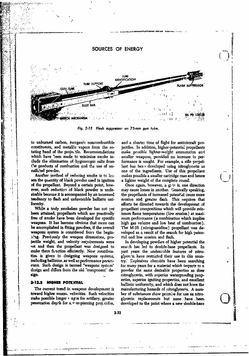
V -
A~ SOURCES OF ENERGY
0•' TUAtE". .: -- •IDENTIFICATION
TUBE SUPPORT FASH SU"
Fig. 3.15 Flash suppressor on 75-mm gun fube.
to unburned carbon, inorganic noncombustible and a shoiter time of flight for antsIircraft pro-censtituents, and metalLc vapors from the ro- jectiles. In addition, higher-potential propellantstating .and of the projeLtile. Recommendations make pessible lighter-weight a m d,,on arA-whib have been made to minimize smoke in- smaller weapons, provided no increase inchide the elimination of hygroscopic salts from formance is sought. For example, a rifle prepel-6t'e products of combustion mid the use of un- lant has bee- developed using nitroglycerin assulked powder. one of the ingredients. Use of this propellant --
Another me-hod of reducting smoke is tc k-i- makes possible. a smaller cartridge case and hencesen the quantity of blick powder used in ignition a lighter weight of the complete round.of the propellant. Beyond a certain point, how- Once again, however, a g , in one directionever, such reduction of black powder is unde- may cause losses in another. tjenerally speaking,uirable because it is accompanied by an increased the propellants of increased potenti4 cause moretendency to flash and unfavorable ballistic uni- erosion end greater flash. This requires thatfop enty, efforts be directed towards the development of
While a truly smokeless powder him. not yet propellant compositions which will provide min-j been attained, propellants which are practic-ally imum flame temperatures (low erosion) at maxi-
free of smoke have been developed for specific mum performance (a combination which impliesweapons. It has become obvious that more can high gas volume and low heat of combustion).be accomplished in fitting powders, if the overall The M-15 (nitroguanidine) propellant was de-weapons system is considered from the begin- veloped as a result of the search for high poten-etnig. erevigtsly the weapon dimensions, pro- tisl Fad low erosion and flash.|ectile weight, and velocity recnirements were In developing powders of higher potential theiet and then the propellant was designed to sezh has led to double-base propellants. Inmake them fuction efficiently. Now -onsidera- past years the undesilrable features of Ditro-tion is given to designing weapons systems, glyce-n have restrictetd their use i- this coun-Includingballistics, as well as performance'pamra - try: Etx.plosives chemists have been searchingeters. Such design is termed "weapons system" for many years for a material whieh imparts to a• 3 r-- d -d ifru n fro- the old -compionene de- powder the same desirable properties as doessip. nitroglycerin, with superior waterproofing prop-
erties, superior igniting properties, and exellent3-12.3 HIGIE POTe4TAL ballistic uniformity, and which does not have the
The current trend in weapons development is manufacturing hazards of nitroglycerin. A num-toward higher muzziL velocities. Such velocities her of substances show promice for use a4 litro.,make possible longer t mngs for artillery. greaa'e glycerin replacements but none -have -been_penetration dep!h for a. or-piercing proj.ciil.ts, developed to the point where a new-double-base
3-22
MILITARY EXPLOSAVE CHARACTERISlICS
powder can be standardized. "Diglykol, as the t of a search, startc yberIt has been the plicy of ie Ordnance Corps aefore, for the ideal propellant. The UpS. Army
to use nitroglycerin in the propellant powder also took part i this search -omo steloped itsonly when a definite improvement in the specitrc Nitroguanidine Propella.t (S!milp: to Cor-weapon which &res the round is needed. Such dite N).
has been the casnfte arife propellant or whenease of ignition is required to give acceptable 3p12e IMOaiONvelocity uniformity. In mortar ammuvition, espe- his is a muz eve-fold problem inasmuve as theerally in uhe lower zones, the double-base roll extent of the erosion can be ueinized by adiv-sheet powders show vast improvement over asteristics of the propellant, the projectie, andgranuitr powders. In this case higher production 'the physical prope.es and compositions oY the
Scosts of roll sheets and greater hazards of nitro- allors used in the gun a dbe.rgly-erin manufacture are justiEa le to obtain Considering propellant requirements only, the
balltice reauirements p problem is to achieve high potential (which givesAlthough foreign powi e have t--h,ded (in ger - high muha le velocities) and yet hase low tem-
eral) to use nitroglycerin in double-base artillery peratures of combustion. 9me use of additivespropellants, early in Worbl War 1I the uermans has helped a great deal in this requeentshowed a tendency to dli ict away from the useof nitroglycerin propellantl.;. The main reason ts12e OfudATed tsn Iffwas the difaculthi and dangy r of manufacturing A major recurin•g expense to the armed serv-nitroglycerin, as well as shortage of raw ma- ices l s the necessity for maintaining continualterials. Contributing factors iticluded theN sforage surveillance of ammunition. In order to help- ~diffiulties of nitroglyo-:,An pc-.vdcr in hot. climates keep this eqwnen !ow it. is essential that propel-
Ssuch as Africa where the high temperatures fonts have as long a storage.life as possile. ForScaused shorter storage fife, as well as great ero. example, a large number o- Wi-mm H.E. rounds
sion of gun bores. thathe Ge rmans maadeo aed during World War . Post-wA propellant havk'ig nitrocellulose and diethyleneh surveillance tests showed that the dropemlant ins
glycol-dinitrate as its principal explosive ingredi- these rounds had deteriorated to such an extenteats and called this Diglykox." It was usedin us that the original p allistic Pwieormance could nomm ammunition, and rocketsa longer be expected. As a resulto these rounds
The British developed Cordite N for many b , had to be opened and the propellant chargesthe same reasons that the Germans developed adjustei.
3-13 PROPELLANTS FOR ROCKETS
A propellant is a compound or mixture which suitable for use depends upon the demandcontains in the correct proportions a fuel and an placed upon the rocket. in general, small, smalleroxidizer which will support high-performance thr•.t, qidck-burning, but hi& pressure MmE0i,,
combustion. While oxygen is the most common use solid propellants while aon.ge, high-thmstoxidizer, fluorine, chlorine and other elements long, turning, low-premre motors use ?jquidwill likewise oxidize fuels. preeeiants.
Such propellants may be solid, liq,.id, or -,n Oteal rocket propellant should posses 1ýegaseous. In gun propellants solids have been in followfitg characteriestisfavor up until recent years; in rockets both solid (a) IUniform ignition and }turing.
O and liquid propellants have found wide-spread (b) R eproducible composition with eom-tmat,asei -,Gases :are too bulky per unit weight to be .be'at e x plosi.-on.
efficis* propellants. The type of propellant most (c Smokelessness.
3-23
S...... ......... _ _ . _•_. .
SOURCI S Of ENERGY
(d) Flashl ,sness. Application of this concept to rocket propul-(e) Stability in strage. sion theory will be discussed in Part 2 of the'(f) Low sensitivity to temperature variation text.
and high resistance to fracture or defori-iation atextremes of temperature. 3-13.1 CURRENT SOUD PROPILLANTS
(g) Availability, cheapness, and safety inmanufacture. Solid rocket propellants may be classed into
In addition to these, solid propel!ants should three general groups: double-base pr.pcl.nt,-.possess. cast perchlorate propellants; and composite pro-
(a) Well-defined, reproducible, and near con- "liellants.stant rate of burring. (a) Double-base propellants. These propel-
(b) Noahygroscopicity. lants usually are known under the trade name• • •,/.) Ability to be worked into gr'ains of widely "Ballistite." Ballistite as used in rockets is a solid
varying sizes, shapes, and bumni.ng times. solution of nitroceilulose and nitroglycerin in(d) Adequate mechanical and phys'ral prop- roughly equal proportions with usually about 5
erties to allow it to be "cycled" thlough extremes to 15% additives. It has good performance, anof temperature without cracking and have suffi- IOP of over 200 seconds, and produces negligiblecient strength to prevent "sagging' at highei smoke. It is limited by its temperature sensitivitytemperatz=es, or imbrittlement at low tempera- (almost 1% per *F). It is fairly difficult and dan-tures, gerous to manufacture.
Liquid propellant; should additionally possess: (b) Cest perehlorate propellants. This type(a) Low toxicity. comprnises our largest tonnage of solid rocket(b) Low ecrrosiveness. propellants. Two of the better known ones axe(c) Ease of bandlu-3g. Calcit and Thiokol. Calcit is a h -terogeneous
Of all propellants yet considered, no single pro- mixture of aboiut h' asphalt-oil fuel with about Ipellant possesses all of these characteristics, for perchlor.. oxidizer, having a specific imp'dsesome are obtained at the expense of others. vround 185 -econds. It was developed at Cali-
Propellants particularly must be rated or corn- fornia Institute of Technology during Worldpared from a performance standpoint, because a War 11. Thiokol propellants incorporate the
"• logistcally periect propellant might have such iý perchlorate oxidizers in a matrix of ,polysulfide
S-+L'w• w t'•_ nce rating as to render it useless rubber. They have a specific impui'c of aboutfrom strictly military considerations. The two 180-215 seconds, good tewpertre i mits, and
most imporiaul rocket performance parameters reduced ieemperature sensitivity.are the constancy of burning rate over the re- (c) Composite propellants. These propellantsquired temperature range and specific impulse. contain ammonium picrate, potassium or sodiumIt shoald be rem'embered that rocket motors are nitrate, and a plastic binder. They tend to bethrust-producing power plants and that the brittle at low temperatures.greater the thrust per pound of motor weight, Small (6-8 inch diameter of motor and smaller)the more desirable zhe unit. Specific impulse I, solid propellant rockets have in recent yearsis the ratio between the thrust and the number enjoyed a wide variety of uses because of their out-cf pounds of propellant consumed per second. standing thr'st-to-weight ratio and relative sim-In other words, it is the thrtut that would be plicity. However, because of limited web thick-delivered if the prope.lant were consumed at the nesses in double-base propellant motors (difficult
Sate of one pound per second. "lie equation for solvent evaporation limits web), and because ofspecific impulse is: slump (s.g due to cantilever loading by its own
weight) and nozzle bum-out in single-base pro-pounds force of thrust pellants, only today are large solid propellant
, pounds of propellant consnied per wecond rockets enjoying wide acceptaac-,a Also, the lackof ability for precise fael shnt-of- has deterred !--N6
lb the use of large solid propeilant rocket motors inirtn units of of abltso=rcs ol hAefhsdtre
t t ) missiles. This de.6ciency too, has been recently
I3-24
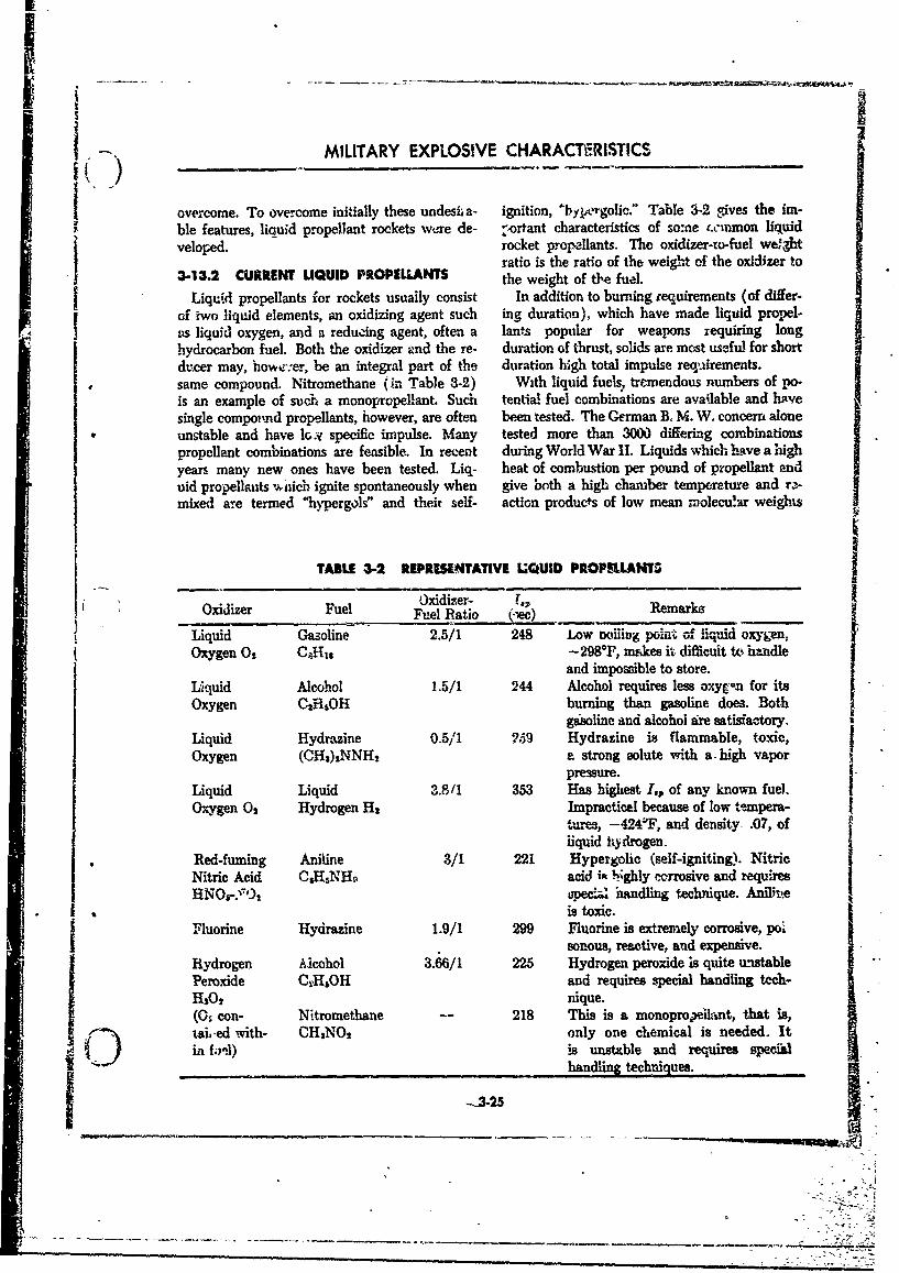
MILITARY EXPLOSIVE CHARACTERISTICS
£overcome. To overcome initially these undesii a- ignition, "byporgolic." Table 3-2 gives the im-ble features, liquid propellant rockets we~re de- -ortant characteristics of somne 4cminmon liquidveloped. rocket propellants. The oxidizer-to-fuel we'llgt
ratio is the ratio of the weight, off the oxidizer to3-13.2 CURRENT LIQUID PROPELLANTS the weight of t&e fuel.
Liquid propellants for rockets usually consist In addition to burning requirements (of differ-of iwo liquid elements, an oxidizing agent such ing duration), which have made liquid propel-as liquid oxygen, and a reduzing agent, often a lants popular for weapons requiring longhydrocarbon fuel. Both the oxidizer vnd the re- duration of thrust, solids are most useful for shortducer may, ltowe-~:er, be an integral part of the duration high total impulse requirements.same compound. Nitromethane (in Table 3.2) With liquid fuels., tremendous numbers of po.is an example of suc~h a monopropellant. Such tential. fuel combinations are available and havesingle compor'nd propellants, however, are often been tested. The German B, M. W. concern alone
unstable and have I1oy specific irnpulse. Many tested more than 3000 differing combinations
propellant combinations are feasible. In recent during World War I1. Liquids which have alhighIyears many new ones have been tested. Liq- heat of combustion per pound of propellanlt anduid propellants vuxichi ignite spontaneously when give both a high chamber temperature and r.>mixed ame termed '4hypergols" and their self- action products of low mean inolecu'.ar weights
TABLE 3-2 REPRESENTATIVE LQUID PROPIMANTS
Oxidizer Fuel Oxdiz~er- -.Rmak_______________Fuel Ratio (-ec) mak
Liquid Gasoline 2.5/1 248 Low tooi~iin polat of iiquid oxygen.Oxygen 02OJ1 -298*F, makes ik difficult to handle
and impossible to store.
Liquid Alcohol 1.5/1 244 Alcohol requires less oxyg-n for itsOxygen 01HS0H burning than gasoline does. Both
Liquid Hydramine 0.5/1 269 Hydrazine is flammable, toxic,Oxygen (CH3)2NNH 2 a strong solute with a . high vapor
pressure.Liquid Liquid 3.8/1 353 Has highest I., of any known fuel.Ox;ygen 0, Hydrogen Ha Impractical because of low tempera-
turres, -424'F, and density- .07, ofliquid hydrogen-
Red-fuming Aniline 3/1 221 Hypergolic (self-igniting). Nitric
Nitric Acid CH5NH%% acid it 16gl corrosive and requiresIupecial handling technique. Anfllue
* I is toxic.j Fluorine Hydrazine 1.9/1 299 Fluorine is extremely corrosive, pol
sonous, reactive, and expensive.Hydrogen Alcohol 3.66/1 225 Hydrogen peroxide is quite unstable'Peroxide OWROH and requires special handling tech-H202 nique.
(OS con- Nitromethane -218 This is a monoprowelAnt, that is,C) ised with- CH3NOs only one chemical is needed. Itin fnl)is unst*Lble and requires specia
handling techniques.
$ --t
I
SOURCES OF ENERGY
•: . ,', are best.. Cmeally, propellants having a large oxiilizing (and hypergolic) nature of some, scruweight percent of hydrogen in preference to car- pulous care of handling is required Concen-
hon meet these conditions best because of the trated hydrogen peroxide, for example, ifhigher heat tof c•-mbustion of hydrogen an,'; ie- contaminaied with organic matter such as wood,cause the priducts of the hydrogen reaction (H. rags, gasket bits, etc., ma'.y ignite. This hazard"and HO) are lighter than the carbon end j,'rod- has probably been overemphasized in test situa-ucts (CO and (.O). tinF, but will require considerable work in future
yeai-s if liquid rockets are to be truly mobile andeasily serviced.Liqud prr_.-.lant rockets currently are most Present work on liquid propellants is directed
useful where long thrust durations are typical. in large measure today to combustion problemsHence large quantities of propelant usually are and handling considerations. Handling difficul-required. For this reason wh4t apparently at first ties of some liquid propellants are one reasoanglance appears to be a small difference n deasit that solid propellants for intermediate size rocketof the propellant may be, on closer scrutiny, of
engines are increasing in the favor of the services.interest. Thus, liquid propellants are judged in The previous discussion of rocket propellantspart by their density impulse. This parameter is u~akes it clear that solid propellants are not idealobtained by multiplying the specific inrpulse by rocket propellants. While some of the disadvan-
the propellant's specific gravity. The resulting"density impulse" is a measure of the propellant tages can be minimized by careful choicp o• theimpulse as a function of its density. Many of the and poportions, as yet no new ma-
propellant combinations whdsh the German terials have been found which, when used i,
rocket scientists used rated well on this evania- conventional propdlants, produce large scale im-rion.Nitric acidniints ed haatedwensity thimlsev ofa- provements in ballistic properties; a.r are the - -tion. Nitric acid-aniline has a density impulse of poteati•. (in rocketry specific impulse) for2W seconds. Surprisingly, liquid oxygen-hydro- ee'her solid or liquid propellants high enough. --gen is very poor in this regard yielding only 85 Consequently, in the hope of producing new pro-seconds in density impulse. pelants with few disadvantages and greater
st-f igth, considerable work has been directed
In liquid propellants too, due to the highly towards entirely new rocket propellants.
3-14 EXOTIC PROPELLANTS
The conventional fuels of the future are the of the hydroc-arbon petroleum base variety. Oxi-exotic fuels of today. in the popular press the -ation of these fuels caused oxidation of mostlyword "exotic" has been applied in recent years, hydrogen and carbon by rupture of C-H andnot to foreign or outlandsh -fuels, but only to C-C linkages.unusmal ones. A few years ago JP-4 and Žhermical Propellants which have different common link-eddiyv~e (commonly boron) fuels ('zip" fuels) ages such as B-H and C--F can theoreticallywere not in common usage. In a few years liberate greater energy by oxidation than can theperhaps lithium, fluorine, and even ion fucLh common hydroca-bon propellants since greater(such as cesium) will be as commonplace as j,- 4 net energy is available after oxidation of suchis today. A mere p,'oper name for the new fucls linkages. Note that fluorine is the oxidizer andwould be new cr novel rather than "exotic." boron is the reducing agent in such arrange-
Chemical fu~ls liberate energy of association ments. It is also important to remember thatby decomposifio: and rehssociation. Oxidation boron, used as a fuel alone liberates some 29,000(removal of electrons) is most frequently used as BTU's per pound when oxidized which compares
. the mechanism for such a change. Fuels most with some 19,000 BTU's per pound liberated bycommonly used in past years were pred'.minantly hydrocarbons, a 40% increase
3-26

MILITARY EXPLOSIVE CHARACTERISTICS
3-14.1 METAL ADDITIVES above are the "free radicals," or unstable mole-
Metal additives such as boron are increasingly cule fragments. These particles are of interest in
popular. Most typical forms of boron fuels now rocket propulsion since their preseace gives a
in use (or study) are the boranes, such as rocket much higher thrust (through increased
diborane (B.,H,) a poisonous gas, pentaborane momentum discharge) than do chemical fuels,
(BH 0 ) a volatile liquid, and decaborane These pieces of fuel are at present difficult to
(B10H,,) a solid. In liquid propellants, such as reate, have a lifetime of only a few millionths of
hydrocaroons, these can be premixed with the a second. They recombine readily. The fact that
liquid petroleum base, They may be used alone they are present in flames and in common chemi-
as fuel, or they c.an be combined with polymeric cal reactions does, however, give promise of their
bindeas and used as a solid fuel constituent. use as efficient fuels if economical ways can be
Toxicity, and the fact that combustion of fuels found to generate and use them, before they.re-with some borane additives often produces areadily depositing crust or syrup on adjacentparts, has deferred their popularity. 3-14A4 IONIC FUELS
3-14.2 &..UORO COMPOUNDS Still further in the future lies the use of ionic
Compournds containing fluorine show promise propellants. These fuels, as exemplified by theas oxidizers for propellants. Some fluorine com- metal cesium, would owe their use to their abilitypounds presently under investigation include ele- to be readily ionized and discharged as charged
Smental fluorine, halogen fluorides, nitrogen ionic particle-.trifluoride, and oxygen difluoride. Fluorides ere As a rocket fuel, such materials would yield
corrosive and often unstable. Hence, some em- efficient thrust by a contribution to rocket mo-phasis is placed on compound stability. In mentum since their discharge velocities Would berockets fluoride fuels oEer a good balance be- very high (1.4 - 10 ft/se), and would be sub-tween low molecular weight combustion trcducts ject to magnetic acceleration.and high !lame temperature. The use of ionic fuels would be limited to
Lithium fuels, such as LiNF, which utilize, space where drag is negligible since the totalfluorine, are also of current interest. thrust produced by the ion discharge motor
would be very small (about .01 pounds of force,3-14.3 FREE RADICALS for example, for a 150 kw motor) even though
Potentially more powerful racket propellants the particle velocities are very high (13.0 • 101than the newer chemical energy fuels discussed ft/sec) since mass rate of discharge is so low.
REFERENCES
1 J. Comer, The Theory of Internal Ballstics of VI, VII, and IX.Guns, Philosophical Library, N. Y., 1951, 3 P. R. Frey, College Chemistry, Prentice-Hall,Chapter 2. N. Y., 1954, Chapters 26 and 27.
2 T. L. Davis, The Chemistry of Powder and 4 Howsman and Slack, Physics, Van Nostrand.Explosives, John Wiley and Sons, N. Y., N. Y., 3rd Ed., 1948, Paragrapbs 173, 174.1941, Jol. I, Chapters I, IV; Vol. II, Chapters 176, and 346.
3-27
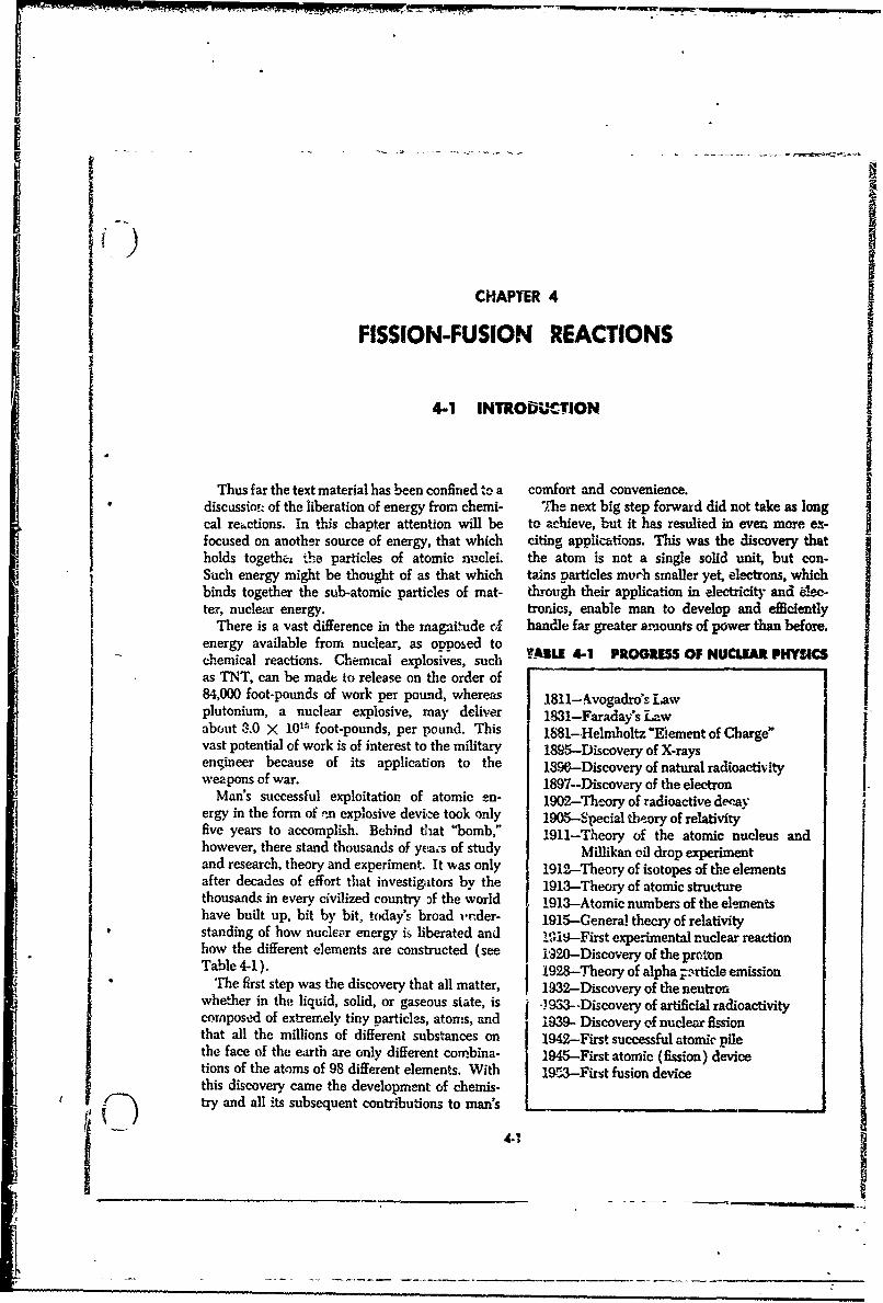
CHAPTER 4
FISSION-FUSION REACTIONS
4-1 INTRODCTION
Thus far the text material has been confined to a comfort and convenience.discassiot of the liberation of energy from chemi- "The next big step forward did not take as longScal re•,ctions, In this chapter attention will be to achieve, but it has resulted in ever. more ex-
focused on another source of energy, that which citing applictions. This was the discovery thatholds togethez the particles of atomic nuclei, the atom is not a single solid unit, but con-Such energy might be thought of as that which tains particles murh smaller yet, electrons, whichbinds together the sub-atomic particles of mat- through their application in electricity and 6lec-ter, nuclear energy. tronics, enable man to develop and efficiently
There is a vast difference in the magniude of handle far greater amounts of power than before.energy available from nuclear, as opposed tochemical reactions. Chemical explosives, such TABLE 4-1 PROGRESS OF NUCLEAR PHYSICSas TNT, can be made to release on the order of84,000 foot-pounds of work per pound, whereas 1811- Avogadro's L.awplutonium, a nuclear explosive, may deliver 1.B31-Faraday's Lawabout 3.0 X 101's foot-pounds, per pound. This 1881-Helmholtz "Eement of Charge"vast potential of work is of interest to the military 1895-Discovery of X-raysengineer because of its applica tion to the 1396:-Discovery of natural radfoactivItyweapons of war. 1897--Discovery of the electron
Man's successful exploitation of atomic en- 1902-Theory of radioactive dewayergy in the form of .-n explosive device took only 1905-Special theory of relativityfive years to accomplish. Behind that "bomb," 1911-Theory of the atomic nucleus andhowever, there stand thousands of yea;s of study Millikan oil drop experimentand research, theory and experiment. It was only 1912-Theory of isotopes of the elementsafter decades of effort that investigators by the 1913-Theory of atomic structurethousands in every civilized country Af the world 1913-Atomic numbers of the elementshave built up, bit by bit, today's broad unr der- 1915-Genera! thecry of relativitystanding of how nuclear energy is liberated and I'i --First experimental nuclear reactionhow the different elements are constructed (see i92o-Discovery of the protonTable 4-1 ). 1928-Theory of alpha 1.nrticle emission
The first step was the discovery that all matter, 1932-Discovery of the neutronwhether in the liquid, solid, or gaseous state, is .1933--Discovery of artificial radioactivitycomposed of extremely tiny particles, atoms, and 1939- Discovery of nuclear fissionthat all the millions of different substances on 1942--First successful atomic pilethe face of the earth are only different cow-bina- 1945-First atomic (fission) devicetions of the atoms of 98 different elements. With 19r3-Firt fusion devicethis discovery came the development of chemis-try and all its subsequent contributions to man's I
A _ _ _ _ _ __ _ _ _ _ _ _
I7
K|
SThe third, and to date, the most spectacular chemical reaction for securing power, such asstep, has been the disco'•ery that the heart of the the burning of coal, wood, or gasoline, the poweratorm:'the nucleus, is also composed of small in- produced comes only from the rearrangement of
._ i&idur~l particles; that one element differs from the atoms in the substance. lit a typical mole--i!•=ianc-the only in the number of these particles cule of coal, wood, or gasoline, the atoms are
Sin its lett; that one element can be converted arranged in one way, and in the products of
put -ane inadffrn
Sco~~~~~mbustio:n, the atoms are an'nein.diertinto ,auother by chiiging the ntumber of these cS.....way. There is no change in the number or char-
particle.s; and that such changes can be utilized"• to prodfice millions of times as much energy as ande of this catoms, ohnlry itheliraangtement,-
Thany elet,-ntrical or ch ei the most pt l hemr is released. This is true whether theUntil 1h 5. onby the comparatively tiny ofergy comes from the burning of coal, wood, or
aamounts of energsi stored of the outermost pringes gasoline; from the explosion of TNT, or fromrof, ther only n e aoumbe oti fd. In every type of chemical reaction in storage batteries.
4..2 ATOPA•IC STRUCTURE
4in, i ILWeu NTS ANDe ATOMS nucleus. ere neutru, w as a neutr ctharge. Pro-A;it.eemen" may be deinted as a substance tons and nteutrons often are referred to as nu-
pArti;a cannot b sb separated by chemical means cleons becawT e both exist within nuclei. Ar-.• :- "ýu-" " nucleon is much heaavier than an electron. Itnto b p adces different from itself. The proper-
atin o 'an element o rigipate oin the atoms that takes about r840 electrons to weigh as much asUn tip the elemeyt; consequently, the atoms one nucleon. Therefore, most of the weight o
aof'u ent elements are not the same, An atom an atom is concentrated within its nucleus (see
.W hii'is ;the smiallest part of'an element that still Table 4-9).retains the properties omf the element. nehe numbei of protons in an uncharged atomAlthough atoms of one element differ atom is equal to the number of electrons. There can
those of another, all atoms have the same geniral be from 1 to 100 or mor protons in an atom.
, struv:'lxr e and often are described by comparing Ile number of protons in an atom determines itsrthem with bn soar m tste l. At he pper- s characteoiqcs as an element. Ffar example, allevery atom is a n ri g teus with positive electrical atoms of hydrogen have I proton; all atoms of-charge. Moving. about t o nucleus in orbits, helium have 2 protons; all atoms of txygen lavemuch like planets move around the sun, are a 8 protons; and an atoms of ct anium have 92 p(se-n smtber of particles calof eleectrons. The elec- tons. The number of protons in an atom is the
trons have a negative charge and ae held w thin atomic number of the ato rs, while the total num-the atom by the attraction of the positive nucleus. ber of nucleons (number of protons plus theFtr convenience, the ch rixge of an electron is number of neutrons) in an atom is the atomicassigned the unit -sa st. mass number.
4-2.2 NUCLEAR COMPO•SITION TABLU 4-2 ATOMIC PARTICLES-- I Physicists now recognize at least ten di~re_,t Patce Crg Mss(m)nuclyear particles. This t hxt discusses, however,ge have p als of
rjust two f these particies, the proton and neu- Proton ot 1 1a .58
Stroc. Thle plnitive charge of a nucleus is at- Neutron 0 1.00894tributer oo 'component particles called protons. Electron -o 0.00055i aThe charge of a proton is + 1. A second type of An ainu (atomec maw unit) b equivslent to 1.mei3
particle, called a neutron. also exists, within tho we , grPartmc Chars e a of" atom.

FISSION-FUSION REACTIONS
4-2.3 ISOTOPES 1H1 J1P 3H$
Since atoms were thought of as the smallest Common
divisible particles of matter for many years, and Hydrogen Deuterium Tritium
it was known that the number and arrangement (Hydrogen-i) (Hydrogen-2) (Hydrogen-3)
of atoms gave elements their properties, the pos- The four isotones of helium are written:sibility that atoms with slightly difering masses Hes 2Hel sHe' Hemight possess identical chemical properties wasdelayed until after the discovery of radioactivity.In an effort to logically support the arrangement The general symbol for any atom is then:of the periodic table, the possibility of isotopes, XAatoms with different masses but identical chemi-cal properties, was suggested by Frederick where,Soddy, an English physicist, in 1912. The num- X = rymbol of the element.'ber of isotopes now known totals several hun- Z = the atomic number (number of protons).dred. Among them are many arfcially produced A = the atomic mass number (the sutr, of theisotopes, including ai least 1 radioactive isotope number of protons and the number offor every known element. Isotopes are atom. neutrons, i.e., the number of nucleons).wiih the same atomic number (number of pro- Thus, A - Z = the number o! neutrons.tons) but different total numbers of nucleons.For instance, 92U284, and 62U218, are different va- 4-2.5 MASS OF NVCLVAR PARTICLESrieties or isotopes of the same element, uranium. The mass of nuclei and nuclear particles. sThe element hydrogen has three known isotopes based on a system in which the mass of the &O1
-- indicated schematically in Figure 4-1. atom is 16.00000. The unit of mass is cal a
4-4 sYMoL ymass unit is of the mass of this isotope ofoxygen, and equals 1.660M x 10-2, gram. TheChemists many yews ago prescribed a short- atcnic weight M, of an atom is Its. nas writteni
hand system for describing -'ements. Instead of in me_-. units. The mass of an atom to thethe full name of an element, a brief symbol is ncijresr ,hole number is called its mans number,used, e.g., the symbol for hydrogen is the letter A.H; the symbol for helium is He.
In nuclear physics a subscript is added to thesymbol to shew the atomic number of the ele-ment and superscript -:s used to show which iso-tope of the element is being considered. This T sato particles with no chemical ale.superscript is the atomic mas, number of the * T tie atlet with o. Thus hrment symbols are given a letter abbreviation. Thus, theisotope. electron, with a chare of -1 and negligible mass is writ-
Thus, the three isotopes of hydrogen are ten ._e; the neutron is written W; the proton (hydrogenwritten: nucleus) is written 21
1.
Common Hydrogen Fit. 4-1 m
Fig. 4.1 hsoofpos of hydrogen.
4-3_ _1

ffi.- -opWR
1o
Li+_ SOURCES OF ENERGY -.
4-2.6 CHARGE OF NUCLEAR PARTICLES has a charge of the same magnitude (but of
,py t t c copposite sign). By various ingenious experiments
l In nulezr physifs, the unit of eiectric charge the magnitude of the electronic charge has beenis the positive charge of the proton. This charge accurately determined to be 4.802, x 10-10jV bften called the electronic charge, or the electrostatic units (esu), or about 1.60 x 10⁻¹⁹'ectronie unit of charge, because the electron coulomb.
4-3 RADIOACTIVITY
" I44.1 NUCLEAR INSTALIUTY particle emission, consider the isotope of uranium
Negative electron, are bound to the atom by with 146 neutrons and 92 protons (,2U2). Thiste attraction of the pos.e prmoton. Within the is a naturally occurring isotope but is radioactivejiucleus, however, oraly positive %arges exist, and and an alpha particle emitter. Since the alphathese. charges shoidd repl eaca other. There- particles take away two protons, the "uraniumfore, other forces stiong enough to overcome changes to an entirely new element, thorium, withthe repelling forcms of the protons, must exist 90 protons and 234 nucleons.between rnuc!eous. Since these forces are ofvery short range, acting only between nucleons -. $ BET DECAYclose to one another, it is po.:sible in isotopes It often happens that unstable nuclei emitof -heave•r ceianuts for the electrostatic forces high-speed electrons called beta particles (sym-be%,ee,.'proto% to overcome the strong nuclear bol P), to inoicate that they originate in thex-rces. If this happens, past of the nucleus actu- nitcleus instead of outside the aucleus. The
ally may break off and escape. In other case, source of 8 particles is intcrestinm. since there arerearrangements may take place which lead to no electrons in a nucleus. The paradox is ex-more stable co.figurations 'within the nucleus. plained by breakdown of a neutron into a protonNuclei in which this happens are said to be and an electron. When this happens, the elec4ron"uistable or radioactive. All isotopes with atomic (f particle) is ejected from the nucleus while thenumber greater than 83 are vnaurally radioactive proton is left behind.and many more isotopes can be made artifi-cially radioactive by adding neutrons, protons, 4-.4 GAMMA RAYSor groups of these to a normally stable configura- Previously it was said that an unstable con-tion. The time that it takes for the product to figuration of neutrons and protons in a nucleus isNe half-transformed into the succeeding product sometimes made more stable by a rearingementis called its halflife. It is a measure of the relative of the components with no particles emitted. Suchstability of the radioactive element. In most cases changes are accompanied by radioactivit, in thean atort always breaks up in the same way, giving form of energy. With different configurations ofa second atom and an a orfl particle. In certain the nucleus the components are bound urithcases, some atoms break up in two distinct ways, different energies, and so upon rearrangemeizr
giving rise to what are called branch products. energy is often released in the form of electro-M ALPHA DECAY magnetic waves called gamma rays (symbol y).
They come from the nucleus rather thau from
Natural radioactivity occurs in thfce basic the excitatiun of planetary electrons, as in theways. Many unstable nuclei emit a particle case of X-rays. No change in atomic structurecomposed of 2 protons and 2 neutrons, called an accompanies i emission (A and Z numbers remainalpha particle (symbol a:). This configuration is the same); the only effect upon the nucleus in-also the nucleus of a helium (2HeO) atom and is volved is to leave it with le"s energy abd us o-lyvery stabie. To evaluate what results from alpha with less tendency for further decay.
44
FISSION-FUSION REACTIONS
4-3.5 INDUCED REACTIONS 4-3.6 RADIOACTIVE SERIES
While only three radioactive particles are The step-by-step process by which radioactiveemitted from naturally occurring radioisotopes, elements emit -radiations and change into, otherthere are a great many more types of decay from el-emets and finally reach a more state isartificial isotopes. in addition to alpha and beta called a decay series. The steps from ,2UW toparticles and gamma rays, certain nuclei m ak goTh234 to 9 1Pa '4 described above, repre nt twoemit neutrons, positive electrons, or othvr parti- steps in wh-rt is called the natural radioactivedes. The neutrons are especially important in uranium series, 92U" 8 bleing the original elementapplications of atomic energy for they can cause in the sedi-. Several other steps, not describednuclear fission, a reaction fundamental to atomic here, occur in this uranium series lbefore taaiiityb jexplosions and sources of atomic pow'er. The is reached and raioactivity no longer exists. Thesurplus neutrons from atomic explosions which last step in this process occurs when the elementimpinge on atoms of the earth, induce sufficient polonium (84Po621) emits an alpha particle, andradioactivity in some elements found in the earth becomes the element lead (s2Pbi20), which isin the vicinity of ground zero to be of military stable. This terminates the uraniun series. Thereir .rtance. are four radioactive decay series (see Figurq 4).
41-4 ENERGY, FISSION, AND FUSION
Until a few decades ago two separate laws de- gold nucleus for example, a mass of 79 X 1.00758scribed the conservation of mass and the con- plus 118 X 1.00894 = 198.654 ainu would be ex-servation of energy. These laws were: In any pected if the law of conservation of mass .held.reaction or system, the amount of mass existing It was found by experiment, however, that a goldprior to a given reaction must be equal to the nucleus has a mass of only 196.996 amu; a lossamount of mass present after the rez=tion; and, of 1.657 amu Similar discrepancies have sinceThe amount of energy inherent in the- system been found for every type of nacleus. These dis-before a reaction must be equal to the amount turbing violations of hitherto accepted laws cfof energy present after the reaction. These laws physics were, .'solved in a brilliant work in 1905,of conseirvation were used for many y~ars with- by Albe-t Einstein, in which he showed that massout disproof until deviations were detected by of all rrattt and energy are equivalent, and thatresearch scientists using refined techniques of it is possible for one to be changed into the othei.measurement. One such deviation was a loss in Ali, -t:,h this would seem to negate the laws ofmass within the atomic nucleus, For example, it conivz ation, it did not. Rather, energy andwas known that a free neutron mass is 1.00894 mass _-e conserved as a sum, that is:amu; and a free proton, 1.00758 amu. When 79protons are combined with 118 neutrons to form a (mass + energy)w.•, = (mass + energy),.a.
4-4.1 EQUIVALENCE Of MASS where c is the velocity of light (3 X 10WO c/see). tAND ENERGY For example, if 1 gram is convert'ed into energy,
A major result of Einstein's theory was that tha result is 9 X 10²⁰ ergs of energy.if a quantity of matter of mass m, is converted E n&62 = (1 gmi) (3 X "1010Sqj/wa)2
completely into energy, !he amount of energy " = 9 X 10" 1cr.ete4 is given by the equation: A conception of the tremendous amount of in-
•(ergs) ,= e(gramsi .4- ergy thus liberate-i can be judged bter if itis
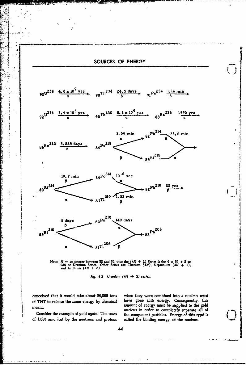
F1A
4a __x_024_. 5n9 d- P 2 1. - min3
i, " 9U-- 90Th• 91
S" E34 3.4x0Syr, 230 8.O3 x 10E4 NER 226 59Y yrs
,r-3. 05 rain 82 h 214-- 26. 8 main
•-•o 6Rn22 3.825 days 8 o218
2 6
S19. 7 rain 8 o 14 10- sec82 21
SB 21 21 2 yrs
it~c I - _ __ ___
8 210
210 a~i Ph 20 6 .m
T206
a ~ 84T
Note: N = an integer between 52 and 59, thus the (4N + 2)Series is the 4 x 59 4-• 2238 or Umnium Series. Other Series are Tcrium 'and Actinum (44V + 3). .NNpufu 4 )
Fi. 4-2 Uranium (4N + 2) sorie."
conceived that it would take about 20,000 tons when they were combined into a nucleus must
of TNT to release the same energy by chemical have gone into energy. Consequently, thisamount of encrgy must be supplied to the gold
Smeansnucleus in order to completely separate all of, Consider the e-ample of gold again. The mass the component particles. Energy of tliis typ ;s C•
of 1.65'7 ainu lost by the neutrons and protons called the binding energy, of the nucleus.
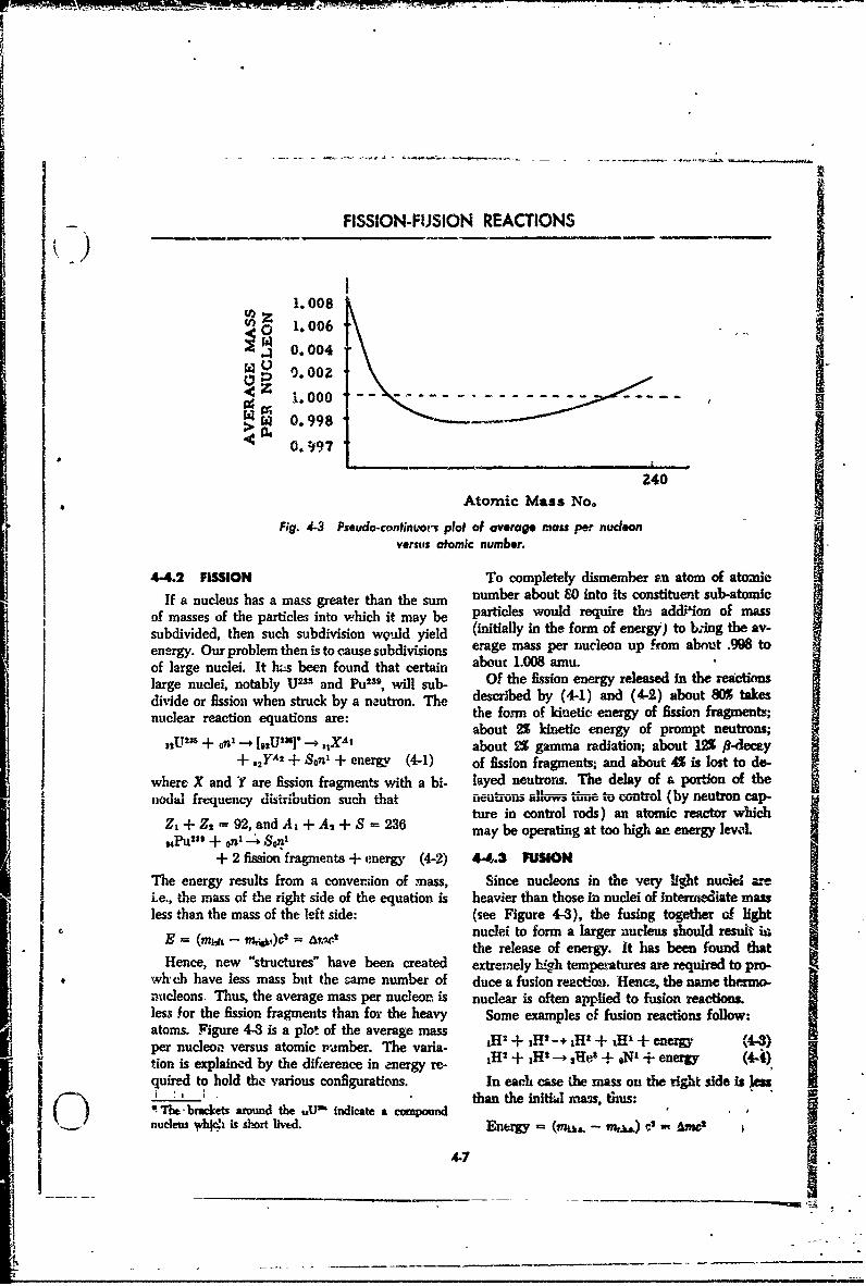
-_ FISSION-FUSION REACTIONS
1.008U) 0 1.006
W 0.004D 9.002
W; 0.998 4------
240
Atomic Mass No.
Fig. 4-3 Pseudo-continuort plot of aoverag* mass per nudconverst atomic number.
4-4.2 FISSION To completely dismember an atom of atomicIf a nucleus has a mass greater than the sum number about 80 into its constituent sub-atomic
of masses of the particle; into which it may be particles would require the addilion of masssubdivided, then such subdivision weuld yield (initially in the form of energy) to king the av-energy. Our problem then is to cause subdivisions erage mass per nucleon up from about .998 toof large nuclei. It hks been found that certain abouc 1.008 amu.large nuclei, notably U2- and Pu2", will sub- Of the fission energy released in the reactionsdiide or fission when struck by a n~utron. The described by (4-1) and (4-2) about 80% takesnucideaor rcion wheqnst y arne:. - the form of kinetic energy of fission fragments;about 2% kinetic energy of prompt neutrons;
"DIUM + OnI _ [*'U]"- + ,IXAt about !% gamma radiation; about 12% 0-decay"+ ,2 )YA + Son' + energy (4-1) of fission fragments; and about 4% is lost to do-
where X and Y are fission fragments with a bi- layed neutrons. The delay of & portion of thenodal frequency dismbution such that neutrons allows Wne to control (by neutron cap-
Atre in control rods) an atomic reactor whichZ+Z = 92,and' A +A + =236 may be operating at too high an energy level,,~Pu 23' + onil -4 Son
+ 2 fission fragments + energy (4-2) 44.3 FUSIONThe energy results from a conver;ion of mass, Since nucleons in the very light nucel are-i.e., the mass of the right side of the equation is heavier than those in nuclei of intervieZiate massless than the mass of the left side: (see Figure 4-3), the fusing together of light
E = (mw- mj&,i)c2 =nuclei to form a larger nucleus should resut irthe release of energy. It has been found that
Hence, new "structures" have been created extremely hAh temperatures are required to pro-whche have less mass bot the sae number of duce a fusion reaction. Hence, the name thezmo-nucleons. Thus, the average mass per nucleor. is nuclear is often applied to fusion reactions.less for the fission fragments than for the heavy Some examples of fusion reactions follow:atoms. Figure 4-8 is a plot of the average mass (4+per nucleoe versus atomic /,umber. The varia- H H - +H' + H1 + ene " (4-3)tion is explained by the difference in energy re- 1H
2 + *H2 - sXe' + oN' + energy (44)quired to hold the various configurations. In each case the mass on the right side is lea.I) ' I' )' than the initia mass thus:SThe-brackets around the uU' indicate a compoundSnucleus /hlq, is short lived. Energy (mAm. -- c,') 0 Aiwt
4-7

SOURCES OF ENERGYH4.4A NUCLEA ENIMAGY R .00427 X 931 =3.98 MevSince nuclear masses are ordinarily given in jH + "• 1 --+ 2Hes + on' (4-6)
' emu (1/16 the miss of an ,016 atom), it will be 4.02942 3.01700instructive to compute the energy which is 1.00894equivalent to1ainu 4.02594
4.02942E- mt, aiu - 1.66 x 10⁻²' gm -4.02594S(ers) - 1.66 X 10-"2 X 32 X (1010)mS- 1.92X 1•* rgeAm = .00348
4-9.3 X 10- ev - 931 M E .00348 X 931 = 3.24 Mev•- •Other fusior reactions might prove useful.
,. I Assurming the mass of right side of (4-1) is .215 Otefuiiraconmghpoeusu."eAssd b h mas ofision sis Consider, for example, a lithium (4-6) tritiumamu less than the mass of the left side, the energy reaction.Sreleasedt by this fission is:recin
very hi931 X .2i5 I 290 Mev 2Lia + tHs o on' + 22Hel
Table 4-3 gives the mas.es of several different tempisotopes. With the aid of this table, the A for 1.00894
svr promising fusion reactions can be corm- 6.01697 4.00390puted. 3.01702 4.00390
9.03399 9.01674TAMU 4-4 ATOMC MISSES OF SOME 9.03399
PARTICLES AND LIGHT ISOTOPES -- 9.01674
z Element A Mass (ainu) A~m = .01725Ee n A M s( u E = .01725 ainu X 931 Mev/amu (
0 Electron 0 0.00055 = 16 Mev0 Neutron 1 1.00894"I Proton 1 1.00758 Note that besides 16 Mev of energy we have also1 Hydrogen 1 1.00813 gained, by this reaction, a neutron which might
(Deuterium) 2 2.01471 be useful to produce fission.(Tritium) 3 3.01702 The. possible use of deuterium, tritium, and2rHelium 3 3.01700 lithium in fusion reactions of commercial or2 H3.07030 military importance would be influenced by cer-4.00390 tain of their characteristics. Deuterium occurs3i6 6.02090 naturally (about .015% of all hydrogen is JH2); it
7 7 .01827 can be separated (at considerable expense) from8 7.01822 water. It is useful since it can be made to fuse- 8.02502 more easily than H1.
To find the energy released by the deuterium- Tritium does not occur ,naturally and mustdeuterium reactions (4-3) and (4-4), the follow- therefore be produced in an atomic reactor (ating simple calculations can Ie carried out. tremendous expense). Further, tritium is radio-
active and has a short halflife (or the order of 12V~~tiry voyars ). Wsi meansnt hat- 4is ni-lllu =d, ... 2• h=-
1HI + H" -" 11H1 + 1H1 (4-5) a limited sheiLife. HowevrT, it tan bo! made totemrp fuse more easily than deuterium.
2.01471 3.01702 Lithium occurs naturrlly and is, relatively
2.01471 1.00813 speaking, cheap.The tremendously hifgh temperatures required4.02942 4.02515 to produce fusion reactions can be attained most
4.02942 simply by fission reactions. Fission reactions are-- 4.02-515 rontrollahk-. It if. desirable, therefore, to go to
Am - .00427 a more detailed examination of these reactions.
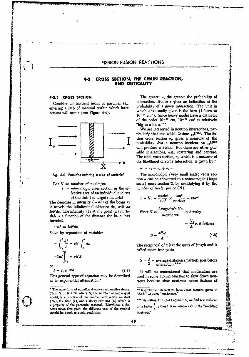
* )FISSION-FUSION REACTIONS
4-5 CROSS SECTION, THE CHAIN REACTION,AND CRITICALITY
4-5.1 CROSS SECTION The greater r, the greater the prnbabiliiy of
Consider an incident beam of particles (10) interaction. Hence a gives an indication of the
entering a slab of material within which inter- probability of a given interaction. "The unit in
actions will occur (see Figure 4-4). which a is usually given is the barn (I barn10-24 cm2). Since heavy nuclei have a diameterof the order 10-12 cm, 10-24 cm 2 is relativelyI' "big as a barn."
We are interested in neutron interactions, par-ticularly that one which Zssions ,2U235. The fis-
t.sion cross section o-, gives a measure of theprobability that a neutron incideut on 2Uu
Will produce a fission. But there are other pos-sible interactions, e.g., scattering and capture.
SThe total cross section, a%, which is a measure ofthe likelihood of some interaction, is given bya , US •+ ar + of+ -..
Fig. 4.4 Particles entering a slab of material. The micmoscopic (very small scale) cross see-e n o ltion a can be converted to a tnacrdoopic (large
SLet N = number of nuclei/cc scale) cross section Y, by midtiplying it by theu mierosconic cross section or the ef- number of nuclei per cc (N).fective area of an individual nucleus nuclei cmof the slab (or target) material I - No = nucmei = e m3 1
The decrease in intensity (- dl) of the beam as m nules•it travels the infinitesimal distance dx, will ,e Avogadro's No.IaNdx. The intensity (1) at may point (x) in the Since N = X densityslab is a function of the distance the be.en has atomic wt.traveled. ' P, it follows:
-dl = laNdx i fA
Solve by separation of variable- Z = No. (4-8)
_(rd 'dl f d A
-- 1 , The reciprocal of I has the units of length and is0 called mean free path:
-1-ni11 = ONX iA , .... average distance a particle goes before
or 7- in(teraction.'
I = 10 e-,YX (4-7) It will be rememilered that moderators areThis general type of equation may be described used in some atomic reactors t. slow down neu-as an exponential attenuation.* trons because slow neutrons cause fissions of
"The same form of equation d6scnhes radioactive decay. " Ihaprobible interactions have cross sections givme inThus, N = Ne -At where N, the number of undmcayed "sheds" or even "out-houses."
in.uclei, isa untio, of the nmnbcr with which we dartn(NM), t6,c time (t), and a decay constant (X) which is 0** BysettingX in (4-1) equal to, wefindL, h reducedk~ok a pr-eke of the particulat material. Elsewhleý X de- by a factor thus is sometimes called the 'e-oldingnotes mean free path. the dileteint uses of the symbol e.hould be noted to avoid confusiozr. thickness."
4.9

SOURCES OF ENERGY
U23 better than fast neutrons. This fact is more escape from the mass of fssionable material with-r'nperly statedds. The fission cross section for out having entered iaito ; fission; or, many areU-l" is greater when the velocity ('.nd thus merely scat,.-"red '•.id slowed down to impotentkinetic energy) of the incident neutrons has a velocity by "bNiliard ball"-:ype impacts with
.ert.in range'uf values. In general we may say nuclei.that, cross seciion, !%re highly energy depend-ent*4-5.4 CASS OF CHA!N REMLIIONS
a. The idea that only U2•'5 and utonium ae fis- AND CRITICALITY
sionable is erroneous. With neutrons of svuficient Depending upon the relative frequency of these,energy UW'", protactinium, and thorium can be events, chain reactions have been classified infissioned. The reason these reactior,s are rot three types that may occur in a mass containingmore important is that neutrons of required en- fissionable material: (1) nonsustaining or con-.ergyare hard to obtain. vergent; (2) suztaining; and (3) multiplying or
divergent. In a nonsustaiming reaction, the" 9.. CHAIN REACTION chance that a neutron will tscape or become
When it was discovered that the fission of a captured is much larger than the chance that itnucleus, caused by a neutramn, results in the emis- will cause fission; therefore, the chain reactionsion of 2 to 3 neutrons, a startling possibility was dies out quickly if started-. In a sustaining reac-suggested. If most of the neutrons emitted could tion the chances of neutron capture or escape areeach be made to cause another fission resulting in less, such that on the average, of the 2 or 3,the emission of ii:ore neutrons, in a few genera- neutrons produced per fission in turn will pro-ti•us the number of free neutrons present could dtice a fission itself, and the number of fretbe made to increase astronomically. The fissio, neutrons remains fairly constant with time. Th;-
process then woihd proceed at an exponentially is the desired condition for a source of nuclear *
,increasing rate -until all of .he fissionable ma- pow;tr since a constant energy output results. -
terial had been disintegrated. Due to the high litially, in a multiplying chain reaction, an av-speeds of these fission neutrons ani due to the erage of more than one neutron per fission willnegligib!e time rv,--uired for a fission to b tmam- go on to produce additional fissions with a rapidpleted, ik might be possible for a a•'emendous increase in neutron population and fissions oc-amount o3f enevgy to be released in a small frae- curring per unit time. This type of reaction istion of a second. The process could result in an essential to a nuclear weapon.exp.olrion; or if the process could be contiolled, One thing that must be done to achieve a mul-it could serve as a nuclear source of usable tiplying chain reaction is to minimize escape andpower. This process, waci e the product neutrons capture, for these effects r,'sult in an unproduc-of an initial fission produce additional fissions, as tive loss of neutrons. Studies of capture effectsdescribed above, is called a chain reaction. have been made and, briefly, it has been found
thba capture varies with the energy (or speed)4-5.3 NEUTION REACTIONS of the neutrons which strike a nucleus,. Fortu-
Several possibilities, which tend to impede the nately, for pure samples of some materials, there
occurrence of a chain reaction, exist for fission are fairly wide ranges of energy for wiich fissionn~eutrons. Often, neutrons ar. captured by a processes dominate over capture. However, tenucleus without producing a fission: they may be 16ss of neutrons through the surface can retardncptured by a nonfissioning impurity; they may a chain reactim even ki the best materials, if thec mass is small. By increasing the amount of ma-terial, the probability that a neturon .wil escape
"This fact can be explained qualitatively by realizing moran be nuced because whicha largern olume ontainSctt~hat there is a wave length associated wlit a mviang par- moenciwth hchaetrnanneattice which depends on its velocity. Whev the velocity before reaching the surface, or, in other words,(and thusb the wave length) of the particle attains a increasiz.g the diameter of a sphere, for example,resonant value, the probability of interaction, is dra- will add more volume, but the volume increasesmatieally incre.sed, at a faster rate than the surface area. Therefore,
4-10
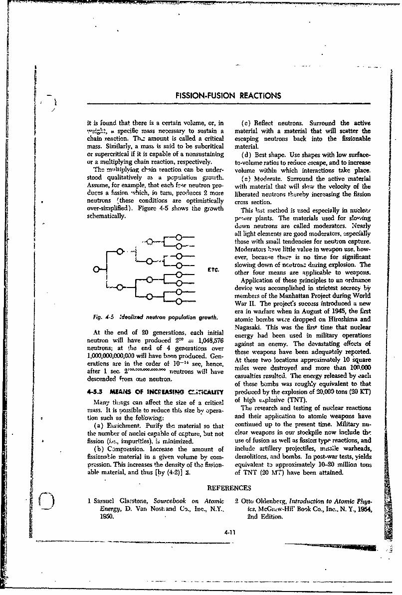
- • FISSION-FUSION REACTIONS
it is found that there is a certain volume, or, in (c) Reflect neutrons. Surround the active,,1 specific mass necessary to sustain a material with a material that will scatter the
chain reaction. Thl. amount is called a critical escaping neutrons back into the fissionablemass. Siniilarly, a mass is said to be subcritical material.or supercritical if it is capable of a nonsustaining (d) Best shape. Use shapes with low surface-or a multiplying chain reaction, respectively, to-volume ratios to reduce escape, and to increase
71he .mltiulying clain reaction can be under- volume within which interactions take place.stood qualitatively as a pcpuiation grovth. el Moderate. Surround the active materialAssume, for example, that each fre~e neutron pro- with material that will slow the velocity of theduces a fission -hich, in turn, pr&Autces 2 more liberated neutrons thereby increasing the fissionneutrons ýthese conditions are optimistically cross section.over-simplified). Figure 4-5 shows the growth This la•st method is used especially in nuclew"schematically. pwer plants. The materials used for sloving
down neutrons are called moderators. Nearlyall light elements are good moderators, eýspeciallythose -with small tendencies for neuti~on capture.Moderators .sve little value in weapon use, how-ever, becauise thter is no time for significant
" EC slowing down of ncutroisz dtring explosion. TheETC. other four means are applicable to weapons.
Application of these principles to an ordnance• device was accomplished in strictest secrecy 1*
members of the Manhattan Project during WorldWar II. The project's success introduced a newera in warfare when in August of 1945, the firstFigl. 4-35 :realized neutron populotion growth. atomic bombs wc.:e dropped on Hiro!;hima and
Nagasaki. This was the firs+ time that nuclearAt the end of 20 generations, each initial e eg a e n u e n mlt r p rto sneuton illhav prduce '~ - 048576 energy had been used in military operationsneutron will have produoed 24 n t = 1,048,576 against an enemy. The devastating eff-ects ofneutrons; at the end of 4 generations over these weapons have been adequately reported.
,00,0,00,0 are win thave orde pof du-4eed. hence, At these two locations approximately 10 squareI e~~~~rations are in the order of 10-" see, hence, mlswr etoe n oeta 0,0after 1 sec. 2100`0-0'00°'00-00° neutrons will have miles were destroyed and more than 100,000
after1scendec. fro neutron s wicasualties resulted. The energy released by eaclof these bombs was roughly equivalent to that
4-5.3 MEAI$S OF INCPgEASIW4G C.r.;TiCAUTY produced by the explosion of 20,009 tons (20 KT)Many tlrigs can affect the size of a critical of high e.plosive (TNT).
mass. It is possible to reduce this size b'; opera. The research and testing of nuclear reactionstion such as the following: and their applicalion to atomic weapons have
(a) Emrichment. Phrify thc material so that continued up to the present time. Military nu-the number of nuclei capable of czpture, but not clear weapons in our stockpile now include th:.fission (i,,;., impuritles), Is minimized, use of fusion as well as fission type reactions, and
(b) Campression. Increase the amount of include artillery projectiles, mi e warheads,fissionable material in a given volume by com- demolitions, and bombs. In post-war tests, yieldspnession. This increases the density of the fission- equivalent to approximately 10-20 million tonsable material, and thus [by (4-2)] 1. of TNT (20 M7F) have been attained.
REFERENCES
1 Sarnuel Glazstone, Sourcebook on Atomic 2 Otto Olenberg, Introduction to Atomic Phys-Energy, D. Van Nost; and Co., Inc., N.Y.. ics. McGr.-w-Hil' Book Co., Inc., N. Y., 1954, _1950. - 2nd Edition.
4-11
ci
!__) EXPLOSIVES ANNEX
EXPLOSIVES MANUFACTURE AND TESTING
A-i INTRODUCTION
As has been learned in earlier chapters, within (a) The manufacture of TNT, the most usedthe family of explosives, different chemical ex- high explosive compound.plosive molecules have different make--,p and (b) The manufacture of the single-base pro-configurations. Such characteristics determiji.- to pellant, nitrocellulose, a typical cannon powder.a large degree, the explosive behavior of sut-, (c) The manufacture of one type of rocketcompounds. As might be expected, such unique propellant, the polymer-perchlzrate type, fre-characteristics mean a dissimilarity of problems qutn'tly used in booster units and aircraft rockets.in the manufacture of these compounds. In oiler Follo,-ing the discussion of these examples,to better understand the problems, consider these typical tesrz to which high explosives and pro-typical examples: pellants are sul.ected are discussed.r A-2 MANUFACTURE OF TRINITROTOLUENE
Of various high explosives expended during synthesized from fractiosiated or cracked pe-World War II, TNT was the greatest in tonmiage. troleum. Facilities for the manufacture of to!ueneFor this reason it was essential that national were established so that approximatei.y twice assources of raw materials, particularly toluene, much toluene was available as was required forwere readily available for TNT pr.-duction. the -manufacture of TNT. This manufacture ofDuring World War I and until about 1939, toluene actually consumed about 0.5 to 1% of thetoluene was procurable from two sources. Prima- amount of crude petroleum that was used in therily it was available as a by-produc, of coke. A manufacture of gasoline during, the same years.lesser amount was found to occur naturally in This had little effect on the supply of motor fuel.certain wetroeeum depostts, but these two sources As exemplified by this case of toluene, and in
ments in World War I. Consequently, vigorous the petrochemicals indust',.y as become onerneasures were taken to increase the supply of of the most important industries which suipporttoluene. City gas mains were stripped of their the manufacture of explosives.small quantities of toluene but still there was an The other raw material required in the manu-insufficient arnount. The dilution of TNT with facture of TNT, nitric acid, is obtibired by nitro- jamr.ionium nitrate was tried; however, the r.'esult- g,.a fixation. In peacetime, nitrogen is mainly
j ing product, amatol, lacked the brisance and blast used in the manufacture of fertilizer. Today, theeffect of TNT. Ammunti-an loaded with amatol nitrogen fixation facilities which were buiit andwa. not as effective as desired. expanded during the war are for the most part
It is doubtful that the Unite:; 't.ates Army busily engaged in supplying the great domesticcould have conducted the vAst operations of and foreign demand for fertilizers, chiefly am-World War II, consuming 'nillions of tons of monium nitrate and anhydrous ammonia. As aTNT, if their sources of toluene had been !hose of result of World War 1U expansion, these facilitiesWorld War I. Fortunately, a process was de- are sufficient to rapidly and quickly supply large"veloped in 1H9 by which toluene could be quantities of explosives raw materials. Using
A-i
- SOURCES OF ENERGY
Stage I Stage 2 Stage 3
CH3 CH3 CH 3 3
-NO 2 NCý 07•1-_ NOZ
+HNO +HNO3 +HNON3I .
NO NO
-Toluene mono- Dinitr otoluene Tr initr otolueneNitrotoluene
Fig. A-1 Tri.nitrafion equation showing some typical polynitrotoluenes.
toluene, the na',ufac'ure )f TNT invol;,es the stops .,Pd an eiuilibrium condition is reachedfollowi•,g proceses: due to the presen-e of excess H.O. Thus, in order
(a) Three stages of nitration: toluene to mono- ic tri-nitrate, or repiace three hydrogens withnitrotoluene, to dinitrotoluene, to trinitrotoluene. three -- iO, groups, water must bee removed,
(b) Washing finished product in water until the temperature raised, and the concentration offree of acid. the nitric acid increased. Since c.emically it is
(e) Purification by remelting and chemical easier to suhstitute thc first -NO.. group than thetreatmenL second, and easier to replace the second than the
(d) Drying and flaking. third, the strength and temperature of the nitrat-Since so many present day explosives must be ing mixture should be highest for tri-nitration,
nitrated, a summary of nitration fundamentals and lowest for mono-nitration. Thus, ti-nitrationis of interest. When the organic compound of toluene is carried out in three stages.toluene (cold), is treated with concentrated nitric A three-stage process, in vvhich heated tolueneacid,; the following reaction occurs: was passed successively through a series of vats
CH3C&H& + H.I"%c -1 CH3C0 4NO +t HtO provided with agitators, and with acid flowingThe end nro(,,,etc ft.V_ ,, '' --" i , 1uniiro- . . , U % e ,,iMvdy bciuretoluene, one of the hydr gens on the toluene and during World War II. Sulfuric acid, an in-having been replaced by tme -NO:, group, giving expensive and effective dehydrating agent, wasthe toliene explosive characteristics. However, used throughout the process to remcve the HO.as soon as the concentration of the nitric acid The resulting TNT was collected, washed, puri-drops below a certain lower limit, the r-action fled by remelting. and dried into a finished form.
A-3 MANUFACTURE OF SINGLE-BASE PROPELLANT
Single-base powder consists mainly of nit-o- These inert materials, of course, decrease theM' lulose ir.to which various additives are in- potential of the powder. However, the resultingcoqporated cc give improved qualities. These product is improved in certain useful qualities.additives are frequently inert materials which The additives generally fou.nd in single-baseabsorb heat, increase stability, or reduce smoke. powders are:
A-2
* -- EXPLOSIVES MANUFACTURE AND TESTING
SDiphenyl!•min-i as a stabilizer, mixed in. Next, the powder is forced throughDibutylphthalate as a coolant; extrusion dies to give it the desired shape. The
Dinitrotohuene or trinitrotoluene to control long tubes of extruded powder are then choppedburning rate and reduce hygroscopicity; into grains of the proper length and allowed to
Triacetin as a gelatinizing ageat; dry until they contain about 0.3% to 0.4% 6f theCentrolite as a stabilizer and coolAn; volatile alcohol-ether solvent.Vaseline as a stabili:er and coolant After a considerable quantity of powder Las
been pfepared as described, it is passell throughIn the preparation of nitrocellulose, cottoa blending tower whee each batch is thoroughly
l tinters (cellulose) are digested by caustic soda mixed with each other batch so that the final
under pressure in order to eliminate oils and powd with ea s h e o at possibl
resinous materials, and then are washed and powder lot will be as homogeneous as possible.
bleached. After drying, nitration is done at 30C (A blending tower may have a capacity of
(86°F) with a mixture of nitric and sulfuric acids. 1,000,000 lb of powder which represents on the
After nitration, the acid and most of the water order of two weeks production.) The ballistic
are removed. Alcobol under pressure is then properties of the lot are then tested and analyzedforced into the block of nitrocellulose to displace so that the proper amount of each lot of powderthe remainder of the water; ether is umed to help can be loaded into the cartridge cases or powderthe alcohol disperse the disintegrated nitrocellu- bags to secure uniformity of ballistic perform-lose into a colloidal state; then additives are ance to meet specifications.
)
A-4 MANUFACTUriRE OF PERCHLORA7E PROPELLANT
As was n;ent~oned in an earlier chapter, pro- while mixing, blend in the perchlorate..pellants formulhted of organic fuel, such as an Mixing is done in a slurry tank or kettle.asphalt-oil mixture and an oxidizer (potassium Viscosity control is critical; into the. viscousG. =.'c.•.n!m nerchiorate), offer the advantages liquid polymer, only particles of great purity andof high specific impulse (about 18 seconb), a controlled size. (or size distribution) are blended.wide range of diesirable physical characteristics, This mix is used to ýii im iz,,ct .•.irts by pour-and competitiv -cost. Such propellants have the ing around a removable mandrel. The rocketadvantages of a very wide range of temperature motors are theu cured, i.e., the rubber oi-ynLrlimits, rugged handlina '•..rcteristics, ease of is polymerized by resting the filled moton rinloading, and simplicity of manufacture. They a heated, constant high-temperature chambtr."were originaly thought of as useful for only After several hours the mtandrel is removed fromsmall rocket motors and jatos carrying not more each motor and the motor is ready for inspectionthsn a few htmored pounds oc propellant. Future (often radiographic) and shipment, or assembly.han al few hned poudse of perylargeropeat. mutoe Manufactured in this way the propellant is
years will see the use of very large rocket motors extremely sensitive to curm.g (Le., heat transfe)loaded with this type ol propellant, rates diring polymerization. In addition, homo-
Thiokol, one popular propellant of this type, geneity is of considerable importance. The distri-is made using a polymerizable rubber base as the bulon, size, and size distribution of.the oxidizer' fuel, to which carefully sized grmaular perchlorate influence the rate of burning. Enginweing; ad-
raeulblne uryothpoyrnd getithlatdcd...is, added. The general scheme is to create a vances in this method of manufacture hav., nemiS•,Pmrefully blended .4hrry of the polymer, and great in the last decade ...
-S A-3

SOURCES OF ENERGY
A-5 PHYSICAL TESTING OF EXPLOSIVES
The present standard riiitary explosives have very nature of high explosives sometimes pre-bein tested by actual use over a lung period of vents the use of highly refined or delicate appara-time and their points of superiority and weak- tus. B,-cause of such limitations, it is difficult to
nesses are known. When a new eyplosive is devise tests of a rigidly scientific type. The re-proposed to meet a particular use, it is compared suits obtained by standard tests on high explo-with the explosive it is intended to replace. It sives usually consist of the measurement of thatis impossible to obtain a satisfactory comparison specific characteristic for which the test was de-by subjecting the new explosive to the test of veloped. Often s'uich testi are so enc-,mberedactual use, because the perik . of time in which with partial measurements of several oth, r char-the old explosive has been so tested comprises acteristics that it is difficult to estimate or •epa-many years. A new explosive, therefore, is com- rate their relative magnitudes. For this reasonpared with the old. or accepted explosive, by it is necessary to consider thc results of the en-subjecting both to certain arbitrary tests, and in tire series of tests before a verdict is renicred onathe interests of economy, rapidity of examination, the relative merit-, of two different high ex-and safety, the preliminary comparison tests are plosives.made on a small scale in the laboratory. If thelaboratory results seem promising, further tests The chart of high explosives (Table A-I)
* are conducted on a larger scale. contains the results of some important physicalPractically all tests of high explosives (both tests. The methods employed to obtain the in-
small anl large scale) are empirical because the formation listed on this table are as follows:
A-5.1 SENSITIVITY TO SHOCK (COLUMN 5) to be tested is placed in the mortar and deto-
ofThes tst is conducted by loading 0.02 gram nated. The deflection of the mortar resultingof the explosive in a cup and dropping a 2-kilo- from the explosion is measured and comparedgram weight on it. By this method the distance with that re.ulting from a standard explosive,througl which it is necessary to drop the weight usually TNT (Figure A-3).in order to secure one detonarion in ten drops, A-$.4 VYLOCITY OF DETONATIONis determined ik inches and given as the sensi- (COLUMN 8%tivity of the explosive. The higher the value, the This test is usually conducted by detonatinglower the sensitivity. The figures given ii. 'olumn5 are the averages of many figures and are cal- an unconfined tube of explosive of a given length
culated to show the sensitivity of the varicus ex- and one inch in diameter. The time for the deto-
plosives as compared with TNT. nating wave to pass from one end of the tubeto the other is recorded and the velocity in metersi• A-5.2 ll~ii. ii ,, CIPW,:t.UMN 6) tuer second comouted.
The trauzl lead block test measures the corn- A-5.5 RELATIVE BRISANCE (COLUMN 9)pazative disruptive effect of an explosive when
fired in a lead block. The volume of thc bore The figures are grams of a unique sand whichhole is meas.ured b4ore and after the explosion will be crushed by 0.4 gram oq the explosive. Theand the expansiw caused by the explosion is test is conducted by luading 0.4 gram of thecomputed to the nearest cubic centimeter. This explosive into a gilding metal shell. The shell isgivei. a measure of the strength of the explosive placed in a bomb containing 200 grams of Ottawa(Figure A-_). silica sand which will pass through a twenty-
mesh screen and still be retained by a thirty-meshA,5.3- IlliSTIC MORTAR (COLUMN 7) screen. After firing, the number of grams of sandThe ballistic mo-tar tests the strength of an that will be sifted by a shaker through the thirty-
explosive. The mortar is suspended by a pen- mesh screen in three minutes is measured anddulun supported on knife edges. The explosive listed as the brisance of i:'e explosive.
A-4

SOURCES OF ENERGY
A-S.6 ADDITIONAL TESTS sensitivity, the explosive is tested for sensitivity
For all types of explosives, the bomb calorime- (a) E-.klosive train tests, to determine theter is used to ob)tain the quantity of hmt given functioning and effectiveness of each element inoff in a closed chamber, the volume of gases the explosive train.
produced, and the pressure developed. Fro, this (b) Setback trits, to insure safety and cer-data the potentia! or' the expi-isive or its capao~ty tainty of action of all components after under-
for doing work is determined. For low explosivas going setback in the gun or set forward onthe product.2 obtained from the explosion in the impact.bomb calorimeter can be analyzed to determine (c) Fragmentation tests, to determine thesmokiness, effectiveness with which a high explosive filler
The rate of combustion of propellant-: varieg will fragment a standard shell.with the speci~c rate of burring and the pre-esure, F-r primers the tests include the comparativeand may be computed by empirical forwuias effect of a black powder flame on the form,based upon experimentally determined values. volumn, and duration of the primer blast. TheThe specific rate of burning is the depth or thick- duratiom, of primer flames is measured in order toness of the layer burned, measured normal to the determine their suitability for the low explosiveburning surface, per unit time under specified train. The impulse (or shock action) at the primerconditions. The rate of burning of a propelling is also testedcharge profoundly influences the ballistic effects In addition, t.here are many other physical testsproduced in a weapon. The temperatures of of explosives. 17he student can appreciate theflames or explosion: can be determined by optical magnitude of the test program by recalling that 4or spectroscopic meth•ds, many hundreds of explosive compounds have
For high explosives, in addition tc impact been or are in the proness of being tested.
A-6 PHYSICAL TESTING OF ROCKET PROPELLANTS
A-6.1 SOUD PROPELLANT TESTING A-6.2 MEASUREMENT OF BURNING RATES
Evaluation of rocket propellants depends in Measurement of rates of burning of solid pro-large measure upon the evalution of their chem- pellants requires specialized equipment andical kinetics. Problems of principal interest are: experience. Measuremenls should be made under
(a) The effect of pressure, temperature, and conditions which approach as closely as possiblecomposition on the linear buarning rate of the those which the propellant is to meet in actualpropellants. use, since the combustion reaction is influenced
(b) The temperature gradients i.a the pra- by a large, and not individuai'y iredictable, *pellant while burning in the motor. number of factors. During tests the propd!ant is
(c) The determination of intermediate chem- immersed ;n its own propellant gases at highical reactions, their mechanisrms, and effects on pressures. Since rates of burning are on thethe burning reaction. ord er of 1 to 2 inches per recond, very good
(d) Final products at reaction temperature. resolution in time is required in order to obtain(e) Effects of composition changes on the acceptable experimenmal accuracy. Since. scaling
above parameters. up of results on small lots of propellant introducesIn recent years each of the above problem:, has errors, a number of separate propellant tests
effort has been devoted to those characteristics ment for small lot manufacturing and calls for
enumerated in (a), above. specialized facilities. 'Tk' illustrate measurerment
A-8
EXPLOSIVES MANUFACTURE AND TESTING5
JI
Fig. A- Bahi otr
3' A-7
TABLE Aol PROPERTIES OF SOME TYPICAL MIL
Sensitivito Shoe.
Explosive* Formula or Proportions Color Density (Drop TfIncheh
(1) (2) (3) (4) (5)
"1. Mercury Fulminate Hg(ONCQ White-Grayish Yellow 3.55 2
2. Nitroglycerin CJHs(C(NO2)3 Pale Yellow Liquid 1.60 2-3
3. Lead Styphnate C6{(NO:)z(O2Pb) Deep Yellow 3.1 2-34. Lead Azide PbNs White - Buff 3.8 3-45. PETN C(CH1 ONO,). White 1.63 66. Cyclonite (RDX) (CH.,,)N(N0s), White 1.65 77. Tetryl C(H,(NO2)3(NCH3NO,) Buff - Lemon Yellow 1.57 8
40/37.7/'20/0.8/1.5, NS/SodNit/8. Nitrostarch BarNit/Oil/Stabilizer Gray 1.6 89. Pentolite 5U/50, PETN/TNT Dirty White - Buff 1.56-1.63 9
10. Torpex 42/40/18, RDX/TNT/AL Gray 1.73 9
11. Tetrytol 75/25, Tetryl/TNT Light Yellow 1.60 1012. Minol II 40/40/20, NH4NOs/TNT/AL Cray 1.65 10-113. Cyclotol (Comp B) 60/40, RDX/TNT Dirty White - Buff 1.65 1114. Tritonal 80/20, TNT/AL Gray 1.7 12
80.1/4/10/4/1/.9, RDX/MNT/DN-T/TN'T/15. Compc•t ion C, Collodion Cotton/Dimethyl Formamide Yellow Brown 1.57 12.116. Picric Acid C#HIOH(NO2)3 Light Cream 1.6 12-117. TN'I CHCHa(NO,)s Bi'M - Light Brown 1.55 1418. Compiion C 88/12, RDX/Oil Brown 1.50 1419. Amatol 5,1/.0 50/50, Ammonium Nitrate/TNT Buff - Dark Brown 3.54 1420. 3omp•sition A-3 91/9, RDX/Wax White - Buff 1.62 1421. A.matol 80/20 80/20, Ammonium Nitrate/TNT Buff - Dark Brown 1.38 1522. Pitertol Z2/48, ExD/TNT Brownish Yellow 1.61 18
Lemon Yellow23. Explosive D CsHi(O'NH4)(NO,)a Orange - Reddish Brown 1.48 18
Listed in oardx oF #heir sensitivity.
Explosives I thru 4 are primazy h explesives.Fxploives 5 thxu 23 are s4condur 1Nsh explosives.
S•p1 ).~m ~mmwmwiLm,• J-M"2
2 _ _ _ ___
L:1-TM
E[XPiOSIVES MANUFACTURE AND TESTING
PROPERaI El Of UM TYPICAL MIUITARY HIGH EXPLOSIVIES
Trauzl Biokc Ballistic Detonation MeltingSeztitivity Test Mortar Velocity Brisance Pointto 'homk (Strength) (Strength) Meters Grams °C Use
Color Density (Drop Test) Cubic % of TNT per of Sand (Castability)Inches Centimeters Setond
(3) (4) (5) (6) (7) (8) (9) (10) (11)Iirayish Yellow 3.55 2 150 - 4700- 5400 15.5-22.4 Expludes Primers and Detonators
Double-Base Powder,ow Liquid 1.60 2-3 515-600 156 8400 60.0 13 Dynamite
Primers, Sensitiz,.r forellow 3.1 2 - 3 120 - 4900 - 5200 9.5- 21.4 Explodes Primers and Detonators"Buff 3.8 3-4 115 - 4000-5000 13.9 - 18 Explodes Detonators and Primers
1.63 6 500- 560 166 8300 61.9 138- 141 Booster Mixtures, Primacord1.65 7 525 162 8400 61.0 200 -203.5 Booster Mixtures
on Yellow 1.57 8 375 120- 125 7500 53.5 123.5- 130 Booster Mixtures
1.6 8 275 96 6100 37.7 Explodes Demolitionshte-Buff 1.56-1.63 9 345 130 7500 53.0 80-90 Buxsting Charge
1.73 9 475 140- 170 7300 57.9 88-95 Bursting Charge
TBurster, Chemical ShelleloW 1.60 10 350 120 73G3 50.0 65-90 Demolitions
1.65 10-11 465 143 5400-5700 40 -141 80-90 Burnting Chargehite - Buff 1.65 11 375 135 7800 51.8 &5 - 100 Bursting Charge
1.7 12 360 118 5500 412.0 80 - 0 Bursting Charge
Brown 1.57 12.5 450 135 8000 55.0 67 Bursting Charge, Demolitions1.6 12- 13 300 106 7200 45.0 1U20.3-122,5 Mixtures
Light Brown 1.55 14 285 :00 6900 43.0 90.2 Bursting Cl:arge1 50 14 360 125 7400 46.5 200-203.5 Demolitions, Bursting Charges
Brown i.54 14 330 109 6500 38.0 80-85 Bursting Chb'rge-Buff 1.62 i4 410 130 7500 49.6 200-203.5 Bursting Chargelisik Brown 1.38 15 360 117 5400 32.0 76 (Softens) Bursting Charge
Yellow 1.61 18 280(?) 100 6972 43.0 (?) Castable Bursting Charge- r. " wDecomposes
"- Reddish Brown 1.48 18 275 96 6500 35.0 265 Bursting Cbarge
A-5/A-6
'. • > ,-• ••• • , .'.••a, ____________• .. .•., •• _ ,.. . . . .
EXPLOSIVES MANUFACTURE AND TESTING
I •--Four elecr'rc leads
Soapstoneinsulator -
seals 0-ring seal
IPredetermi-ned
length P-Popellant strand' along strand
n t opellant mountingbracket (removable)
Timing leads
!IPre!:su3izing tap
Fig. A-4 Pre.suro vessel for measuring burning -. !es to prope.lant as a function of pressure.
of burning rates consder two typicaF n. :-thod, the 4in.e taken for the tuiming to travel between(a) Strand burnir, . A strand c' d•i tr.-,t pt, the ac. ratv known distance along the strand.
pellant about 34 inch in iiameter and 6-8 inches Th'- methco ;3 sailed to laboatory inves.-blong, coate-'- with votie inert plastic to restrict gatiu~n in thai c."iy .-tnai -ziantities oi prnuellantburning to the ends only, is supported by a wire are required for each test. Ht, the strandsbracket in a heovy-walltd bomb prsssurizd to must be carefuilv formulated and exir'uded. ir- [the desired value with inert gas. Through the erties of propellarts oi differing compositiosstrand are passed two electric leads of fine wires
located a known distance apart along the strand, may be checked in ikis way. in ihis method
The strand is ignited and as the strand burns resui!.. rmst be adjusted using empirical daia
an electrical impulse passes into a z"•=ý--ng in order to n'rrect them io ectue? burning ratesdevice, through each wire in turn, as the com- of propellahts imenicred in ihti- own propellant
bustion consumes the strand. Thus, a measure- gases. A drawing of a typxeal strand ,_-.'-g dment can be taken o: t,.e effect of pressure on apparatus :s shown in Figure A.-4.
A-9
SOURCES OF ENERGY
-- '--_- --3.0
U -4----] 7~t --S~~2.0.
-~1.0 V - I z / .Ud
0.3 ... :
I--,--Co I
-. 5 1.0 Z.0 35.Ln Average Pressure(1000 lb. /in. 2 )
MRC PELLANT COMPOSITIONNitrocellulose 57.55(including 123. Z 1% N)
Nitroglycerin 39.96Potassiurn Sulfate 1.48
Ethyl Centralite 1.01Volatiles 1.00Carbon Black .10
Fig. A-5 The eftoed of pi'essure on burning rate of a rocket solid propellant.
(b) Vented-vessel tectiniques. In this equip- and recorded on film using a drum camera. InSmeat the propellant is bu.rned in a simple rocket this apparatus the effect of time on burning roteI motor provided with a variety of nozzles, the may be measured by suddenly dunking the vesselI purpose of which is to provide a means of vary- containing the burning propellant into watermng the pressure. The test motor and propellant during burning. Analysis of the pressure-timeare kept under controlled (and predetermined) curve, coupleM with a knowledge of the rate oftemperature eowditions until needed. The burning, gives data which is the linear rate e-pressure-time curve of the burning charge is bvrmirng in a particular pressure region. A numbermeasured with a -Lain gauge which is part of a of tests permit construct-on of a family of curveswheat'tr'isc bridge. The unbalanced er.,f of the of burning rate as a f'unction of pressure. Typicalbridge is .mpli•.ed, applied to an oscilloscope, curves so arrived at are shown in Figure A-5.
A-10
. . . . . . . . . . . . . .. . . . . . . . . . . .�....... ......... .... ...... . .. ................. . . ....... . .... ....... . .......... . ..... ................. . .... ._ _ . _ _ .. _ _. _ -- - _-_.

E
APPEND)IX
TALIE A-2 INTUSNATION&, ATOMIC WEIGHTS, 1937
-- AtoWemhtc Atomic
Atomic Atomic Symbol Ntmb WeightomSym boN mbe NW eigeghb...
- .. A 13 18.9 7 Mercury ........ Hg 80 200.61
Antimony ...... Sb 51 121.76 Molybdenum .... Mo 42 96.0
Argcn ......... A 18 39.944 Neodymium.... Nd 60 144.27
Arsenic ......... As 33 74.91 Neon ........... Ne 10 2C.183
Barium ......... Ba 56 137.36 Nickel ......... Ni 28 58.69
Beryllium ...... Be 4 9.02 Nitrogen ........ N 7 14.08 1
Bismuth ........ Bi 83 209.00 Osmium ........ Os 76 191.5
B 082 Oxyger- 8 16.0000-Boron .......... B 5 10.22 OO 106.7Bromine ....... Br 35 79 916 Palladium ...... Pd 46 106.7
Cadmium Cd 48 112.41 Phosphorus ..... P 15 31.02
Calum ........ Ca OW 40.08 Platinum ....... Pt 78 195.23
Carbon C 6 12.Q1 Potassium ...... K 19 39,096Cerium ......... Ce 58 1440.13 Freseodymium.. Pr 59 140.92
Cesium ......... Cs 55 132.81 Radium ........ Ra 88 226.05
Chlorine ........ Cl 17 35.457 Radon ......... Rn 86 22.
Chrnmium ...... Cr 24 52.01 Rhodiur....... Rh 45 I02.91
Cobalt ......... Co 27 58.94 Rubidium ...... Rb 37 85.48
Coiumbium ..... Cb 41 92.91 Ruthenium ..... Ru 44 101.7
Copper ........ Cu 29 63.57 Samaritn...... • Sm 62 150.43
Dysprosium ..... Dy 66 162.46 Scandium ....... Sc 21 45.10
Erbium ......... Er 68 167.64 Selenium ....... Se 74 78.06
EurEpium ...... Eu C 13 152.0 Silicon ........ Si 14 28.06
Fluorine ........ F 9 19.00 Silver .......... Ag 47 107.880Gadolinium G. 64 156.9 Soxwii ......... Na 11 22.997Gallium ........ Ga 31 69.72 Strontium ...... Sr 38 87.63Germanium ..... Ge 32 72.60 Isulphur ........ S 16 32.06
Goid .......... Au 79 197.2 Tantalum ...... Ta 73 180.88Elgni-um ....... Hf 72 1786 Tellurium ....... Te 52 127.61
Uslium ........ He 2 4.002 Terbium ........ T 65 159.2
Holmium ....... Ho 37 163.5 Tjallium ....... TI 81 20439
Hydrogen...... H 1 i.0078 Thorium ....... Th 90 232.12
Indium ......... n 49 114.76 Thulium ........ 'Tn 69 169.-Iodine.......... 53 126.92 Tin ............ &1 50 118.70iridium ........ Ir 77 193.1 Titanium ....... Ti 22 47.90
Iron ........... Fe 26 55.84 Tungsten ....... W 74 184.0K-ptor ........ r 36 83.7 Uranium .... U 92 r•07
I Lanthanum . L 57 138.92 Vanadium ...... V 23 50.95
L ........... Pb 82 207.21 Xenon ......... Xe 54 131.3Lithium........ i 3 6.40 Ytterbium ...... Yb 70 173.04
Lutecium ....... Lu 71 175.0 Yttrium ........ Y 39 88.92Magnesium. ... - -- g1 12 24.32 Zinc .... ...... Zn 30 91.22
Manganese. .. Mn 25 54.93 Zirconium ...... Zr 40 91.22
- ~~Dafta foi. fth -,able furnishe by Picau=sy AxieM4
A-I1

7I
SOURCES OF ENERGY
TABLE A-3'' DENSITIES OF CERTAIN GASES AT 0°¢ AND 764 MM PRESSURE
j Density lb per cu ftGas Formula Air = I cu ft per lb
Acetylene ............................ C2H2 0. 73 .07324 13.654Air'.................**-**................ - 1.0000 .0 W072 12.390Ammonia .. . ....................... ML 0.5963 .04813 20.777Bromninel ............................ Br., 5.516 .44525 2.246Carbon dioxide .................. .... C02 1.5290 .12342 8.102Carbon monoxide ..................... CO 0.967.1 .07806 12.810
ChlD NSTe ............................ C12 A D .2 09 4.97bCoal gas .... ...... .................. .- 0.504 .04068 24.58Cyanogen ............................ CN, 1.804 .14562 6.367
Ethane ...................... ........ C2H$ 1.049ý .08470 11.806Ethylene ............................. C:H, 0.9710 .1,7838 12.758Fluorine ............................. F2 1.312 .1059 9.,44;'
Helium .............................. He 0.1381 .011115 89M6Hydrogen ............................ Ht 0.06952 .005612 178.19Hydrogen bromide .... ...... ........ HBr 2.8189 .22754 4•395 _Hydrogen chleridd ............... I..... HCI 1.2678 .10234 9.771Hydrogen fluoride ..................... HF 0.713 .0576 17.361Hydrogen iodide ................. .... HI 4.47"76 .3614 2.767"
Hydrogen sulphide. . ............ ...... H2S 1.190 .09606 10.411Methane ............................. CH4 .5t .0448 22.32Nitric oxide .......................... NO 1.0366 .08367 11.953Nitrogen ............................. N` 0.9673 .07808 12.807Nitrogen dioxide2 ..................... NO, 1.588 .1282 7.800Nitrogen tetroxide2 .................... N204 3.176 .'-5 64 3.900Nitrous oxide ......................... N20 1..'-,30 .12350 8.097Oxygen ..... .. .................... 02 1.1053 .08922 11.208Steamn (at 1000C ) ....... ............. H20 0.46181 .03728 26.824Sulphur dioxide ....................... so-t 2.2638 .1827420 5.473Water gas ............................ - 0.684 .05521 18,11
' Dry atmospheric air at sea level has approximately the following composition by volume:Per Cent Per Qa~t
N-7 78.03 C8. 0.03yd O , f0.........99 HF .7 0.01
A n.......... .. .. C94 are gases ..4 0.002N Not gxaseous under standard conditions. Density is calcu2a0ed assuig molecular volt8.0e
eO. .ual to 22,.411 liters.
= Comjqpwd to air at O'C.
'Dr atm.or this T able furnished by heaainny Arsenal.
i A-12
m pu ixd............S2223 e

APPENDIX
TABLE A-4 SPECIFIC HEATS AT ROOM TEMPERATURES, SOUDS AND UQUIDS
[ Cdtories
Name Fornula Molecular Calories per GramWeight per Gram Molecule or
Gram Atom
Alcohol (liquid) .................. .(JHOH 46.1 0.581 26.8Aluminum oxide ................ A120 3 101.9 0.188 19.2Ammonium chiori'e .............. NH4CL 53.5 0.376 20.1Ammonium nitrate .............. NH4NO3 80.0 0 40? 32.6Antimony ....................... Sb 12N.76 0.0503 6.12Antimonous oxide .............. SblO3 291.5 0.0829 24.2 fArsenic (met.li) ............... As 74.91 U;.0822 6.16
Barium carbonate ................ BaCO3 197.4 0.1030 20,3Barium chloride .................. BaC12 208.3 0.0875 18.2
* Baium nitrate .................. Ba(NOs's 231.4 0.1523 39.8Benzene (liquid) ................. C0H1 78.1 0.406 31.7Calcium carbonate ............... CaCO: 100.1 0.206 20.6Calcium chloride ................. CUC12 111.0 0.1642 18.2Calcium suiphate (cryst. anhyd.)... CaSO4 136.1 0.169 23.0Carbon (graphite) ................ C 12.01 0.165 1.98
Chromium trioxide ............... Cr1QO4 152.0 0.178 27.1Copper sulphate (anhydrous) ...... CuSO4 1159.6 0.157 25.1Glycerin (liquid) ................ CHs(OH): 92.1 0.580 53.4Iron sulphide ................... .FoS 87.9 9.139 122
Lead ........................... Fb 207.21 0.0305 6.32Lead carbonate .................. PbCOs 267.2 0.0971 26.0
J Lead nitrate ..................... Pb(NO0%) 331.2 0.1173 38.8"Magnesia ....................... MgO 40.3 0.235 9.46Mercury (liquid) ................. Hg 200.61 0.03325 6.67Nitric a-id (liquid) ............. HNO3 63.02 0.476 30.00Phospi-rus (Red) ................ P4 124.08 0.1829 22.7Potassium dichromate ............ KiCRzO 294.2 0.182 53.5Potassium carbonate ............. KC00 3 138.2 0.2162 29.9Potassium chlorate ............... KCI0 3 12S.6 0.196 24.00Potassium chloride ............... KC1 74.6 0.164 12.2Potassium ferrocyanide ........... KFe('rN)s 368.3 0.218 80.3Potassium nitrate ................ KNOs 101.1 0.220 222Potassium perchlorate ............ KC1O4 1,38.6 0:191 26.5
Potassium sulphate (eryst.) ....... .K 1 04 174.3 0.182 31.7Potassium sulphide ............... K2S 110.3 0.091 10.0Silica (quartz) ................... SiOs 60.1 0.188 11.3Silver ........................... Ag 107.880 0.05625 6.07Silver chloride (cryst.) ............ AgC1 143.3 0.0878 12.6Silver nitrate (fused) ............. AgNOa 169.9 0.144 24.5Sodium carbonate ................ Na*CO3 106.0 0.2728 28.9Sodium chloride .................. N.CI 58.5 0.208 12.2Sudium nitrate ................... NaNO, 85.0 0,259 22.0
A-13
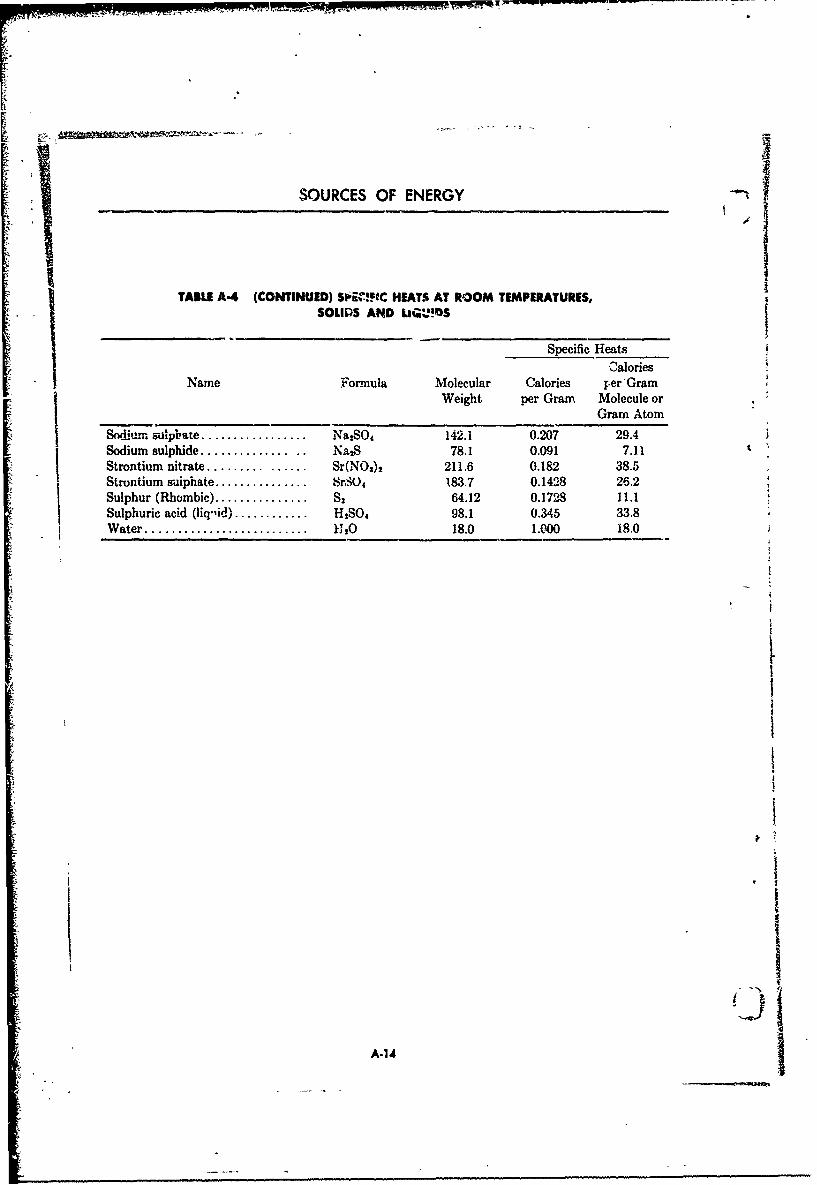
SOURCES OF ENERGY
TABLE A-4 (CONTINUED) SI .1FIC HEATS AT ROOM TEMPERATURES,SOULPS AND LIGUOS
Specific HeatsCalories
Name Formula Molecular Calories y.er'GramWeight per Gram, Molecule or
Gram Atom
Sodium sulpbate ..................... Na2SO4 142.1 0.207 29.4
Sodium sulphide .................. .. NalS 78.1 0.091 7.11 tStrontium nitrate ................ Sr(NO3)1 211.6 0.182 38.5Strontium sulphate ................... SrSO4 183.7 0.1428 26.2Sulphur (Rhombic) ................... S 64.12 0.1728 11.1Sulphuric acid (liq.id)............ HS04 98.1 0.345 33.8Water ...................... ...... K. 18.0 1.000 18.0
AUt
A-14

APPENDIX
f - TABLE A-5 NA'v z,- iLOKMATION rROM' TH EL.MENTS .0T 150 AND 760 MM PRESSURE
Molec Heats of Formation in LargeNeMolec- Calories per Gram 'MoleculeNameFormula ularSWeight Dis-
Gas Liquid Solid Lolved
Acetone ................ CHzCOCH3 58.1 53.4 61.5 -- t0.-Acetylene ............... C2H. 26.0 -54.86 - -Ammonia ............... NH, 17.0 10.9 15.8 - 19.1Ammonium bicarbonate.. NHHCO, 79.1 - - 208.6 -
SAmmonium chloride ...... NH 4CI 53.5 38.9 - 76.8 72.8Amnionium dichromate... (NH 4 2Cr2O7 252.1 - - 420.1 407.4Anmmonium nitrate ....... NH4NO3 80.0 - - 88.1 82.8Ammonium pirt.. .. CaH,(N02)30'NH, 246.1 -- 78.0 69.3!..Aniline ................. CeHsNH, 93A - - -6.4 -4.3 -6.6BAntimoni oxide ......... SbaOS 323.5 - - 1230.9 -6Antimonous oxide ........ 8b2Os 291.5 - - 166.9 -
Antimony sulphide ....... Sb... S 339.7 -1 -1 34. 4 -Barium chlorate ........ Ba(CIO()J 304.3 - - 171.2 167.2Barium oxide ........... BaO 153.4 - - 133.1 16981Barium nitrate .......... Ba(N.O,)2 261.4 - - 238.3 180.0CBarbn peroxide ......... BaO2 169.4 - - 1051.7 -Benzene ................ -I0 78.1 -16.8 -12.0 -9.7 -Calcium picrate ........ [CH-(NO2)O],Ca 496.3 - -- 185.4 187.6Campho: ................ C2 OH, 0 652.2 - - 79.8 -Cane sugar ............. C12,CH1,, 342.3 - - 535.0 -Carbon dioxide .......... C2O 44C0 94.39 -- 100.3 99.1Carbondisulphide... ... . CS2 M62 . -25.4 -19.0 2 -
Carbon monoxide ........ CO 28.0 26.43 - -6.Cellulose ................ C24 400 20 618.6 - 9209 -.Cellulose acetate (penta).. Ca•I•, 02CCHIý)s 372.3 --- 520.0 --
Copper picrate ........ [C.H (NO)1 2HCu 519.8 - -- 60.4 63.7Cyanogen ............... CN6 52.01 - -6. 5 -- -64.0Dextrine ................ CGHI(O2 162.1 - - 242.0 -Dibutylphtlodab e ........ CH 4(COICJI,)2 278.3 199.8 -8Diithyophthalsete ........ Ct oH,(COC2H, 21.2 - 180.3 -Dinitrobenennol (C2th 3 Cd.H4(NO02) 168.1 -0.2 -
Dinitrobenzene (meta).... COH'(N0 2) 2 168.1 -- 6.0 -Dinitrobenzenae (p=) .... C•-,(%NO2)2 1658.1 --- 8.0 -
Dinitronaphlalene (1o8) CsoHs(NO) 1 218.2 -- 2.7Dinitrophenol (2 : 3) .'.. CsHOII(NO2 )2 184.1 - 14.0 -Dinitrophenol (2 :4).... CH 3O (N02)2 184.1 55. -6 5 -Dinitropheaol (2 : 6). ... C6-lOH(NO2)T 184.1 --- 17.0 -Dinitrotoluol (2 : 4) ...... CftP-3oH(NG,) 1812.1 •-12.2 -Dinitrotoluol (3:4),..... C*HsCHs(NO2), 182.1 - 5.1 -Dinitrotolaol (3 : 5) ..... CH&CH3(NO2)2 182.1 -- - 12.0 -Diphenylamine .......... CsH5 NH.CsHI 169.2 - -22.2 -27.6Ethane ............... Cd-i 30.1 25.5 - -
Ethyl alcohol ........... C.-0HOH 46.1 56.0 66.3 - 69.2
A-15

)'
r
SOURCES 0F ENERGY
I •ITAILB A-S (CONTINUED) HEATS OF FORMATION FROM THE ELEMENTS AT*1 -5C AND 760 MM PRESSURE
Heats of Formation in LargeMolec- Calories per Gram Molecule
NaeFruaular_____•.•.Weight Dis-W g Gas Liouid Solid solved
Ethyl ether ............. (CH),O 74.1 39.1 46.8 - -
Ethylene ............... C0I4 28.1 -6.5 - - -
Formaldehyde ........... CHO 30.0 28.8 - -- 40.4Glucose ............... CH2OH(CHOH)4CH'0 180.2 - - 303. 276.Glycerin (glycerol) ....... CHs0H0HOH.CH20H 92.1 - 159.7 163.6 165.1Glycol......... .(CH,OH), 62.1 99.9 112.0 - 99.9Glycol dinitrate. ......... C.H4 (NO3)2 152.1 - 58.7 - -
Guanidine .............. C(NH) (NIl2 )2 59.1 - - 19.2 28.4Guanidine nitrate ........ .CHMNNO, 122.1 - - 79.3 89.2Hydrocellulose .......... C..12H,.,O 342.3 - - 453.8 -
Hydrogen peroxide ....... H102 34.0 -- 46.84 56.0 45.3Hydiogen sulphide ....... P, S 34.1 5.26 9.26 - 9.32Lead a ido. .............. PbN, 291.3 - - -105.9
iLead odde .............. PbO 22,3.2 - - 52.47 1Lead nitrate ............ Pb(NOz) 2 331.2 - - 1083 101.7Lead picrate ........... [C&Ij(NOahOI 2Pb 663.4 - - 82.2 75.1Magnesium picrate ...... [C&H2(NO:)iO~sMg 480.5 .. .. 172.6 187.3
Mannite ................ (CHOH)2(CHOH)4 182.2 -- - 317.9 282.4Mannitol hexanitrete. 01 -IH,(NO)a 452.2 -- 179.. - -
Mercuric oxide .......... HgO 216.6 -- - 21.7 -
Mercury fulminate ....... Hg(CNO)s 284.6 .. - -64.5 -
Mercury picrate ......... [CH2(N02 ):O] 2Hg 656.3 - - 42.8 38.1Methane ............... CH4 16.0 20.3 - - -
Methyl nitrate .......... CH2 O-NO2 77.0 39.9 - --
Mononitrobenzene ....... CJ-INO 123. 1 -11.7 -2.0 0.7Nitric acid .............. HNOs 63.0 35.3 42.4 43.0 49.8Nitric oxide ............. NO 30.0 -21.6 - - -
Nitroacetanilide (ortho).. CSHSN203 180.2 - -- 52.6 -
Nitroacetanilide (mota) ... 0 N1 O 180.2 - -- 54.6Nitroacetanilide (para)... C*H#N2O 180.2 - - 60.6Nitrobenzaldehyde (ortho) C.HPCHONO2 151.1 - 19.9 - -
Nitrobenzaldrhyde (met%). C-H4CHONO2 151.1 W.9 31.6 -
Nitrobenza!dehyde (para). CHICHONO2 151.1 - 19 9 441 -
Nitrocamphor (alpha).... CwHs(N0)O 197.2 - - 85.4 -
Nitrocamphor (phenol)... CioHi(NO2)O 197.2 -- - 125.2 -Nitrocellulose (12.6% N).. CO-H3o.,9Oo.i.(NO:),.sz 1090.0 - 665.5
Nitrocellulose (12.75% N). C2JHIoO10(NO3.)1 1098.6 - - 659.3Nitrocellulom (13.15% N). C,4Hji. 4 O,.4s(NOs)io.&s 1123.3 - - 643.1 -
Nitrocelluloe (13.75% N). C2,,H,,.O,.,,(NOs)to.,, 1129.6 - - 639.9Nitroethane ............. CIHSN0 2 75.1 30.6 37.5 - -
Nitrogen chloride ........ NC13 120.4 - -38.5 - -541iin M11,
Nitrogen pentoxide . N2 O 108.0 -1.2 3.6 14.6 .28•6
A-16

IiT
APPENDIX
TABLE A-S (CONTINUED) HEATS OV FORMATION FROM THE 1EEMENTS AT150 C AND 760 MMl PRESSURE
Heats of Formation in LargeMolec- Calories per Gram MoleculeName Formula ular
Wel~gh, Ds-Weight Gas Liquid Solid solved
Nitrogen peroxide ....... N2O 46.0 -7.4 -12.6 - 25.6Nitrogen sulphide ....... N 4S, 184.3 -19.0 -- -31.9 --
Nit.rogen trioxide ........ N2j 76.0 -21.4 - - -14.7Nitroglycerin ............ CH5(NO3), 227.1 - 85.3 - --Nitroguanidine .......... C'NH N112.NHN0, 104.1 -- -- 12.6 "-
Nitromethane ........... CH3N02 61.0 14.0 27.6 - -Nitronaphthalene (alpha). C1oH7N0 2 173.2 - -2.2 - 7.1 -
Niphenol (ortho) H 139.1 - -56.1 47.2 -
Nitrophenol (para) ....... C6H 4NOIOH 139.1 - -57.0 50.1 -Nitrous oxide ........... N10 44.0 -17.0 -18.7 -- -14.4Ozone .................. 0: 48.0 -34.4 - - -32.5Picric acid .............. C0H2 (NO:.)OH 229.1 - - 56.0 -Potassium carbonate 1C00 138.2 - 275.0 281.5Potassium chlorate ....... KC1O3 122.6 - -- 89.9 79.5Potassium chloride ..... , KC1 74.6 - -- 104.3 99.9Potassium d-zhro. rote .... KCrO7 294.2 - - 481.7 -Potassium nitrate ........ KNOs 101.1 - 114.2 119.0 110.14Potassium pWrchlorate.... KCIOs 138.6 - - 113.5 100.2Potassium pierate ........ C&Hj(N0s)s0K 267.2 - - 110.1 100.1Potessi,•m sulphate ...... KS90 4 174.3 - - 338.5 -Silver ritra& •............ AgNO3 16P.9 - 16.0 30.11 24.66Sodium carbonate ........ NaC03 106.0 - - 272.6 276.2"
Sodium chlorate ........ NaC!O3 106.5 - 79.G 82.34 77.06Sodium chloride ......... NaCI 58.5 - 90.7 98.4 97.1Sodium nitrate .......... NaNO, 85.0 - 106.0 112.5 1V7.4Sodium perchlorate ...... NaCIO, 122.5 - - 100.3 97.25Sodium picrate .......... CsHs(NOt),ONa 251.1 - - 103.4 97.'"Sodium sulphide ......... Na2S 78.1 - - 89.7 105.5Starch .................. (CHio00). 162.1 - - 230.8 -
Strontium nitrate ........ Sr(NOah 211.6 - - 234.4 230.6Strontim-n oxide ......... SrO 103.6 - - 140.7 237.1Strontium picrate ........ [CH(NO2)30]sSr 543.8 - - 196.0 196.8
Sulphur dioxide .......... SOs 64.1 69.3 7E.3 - 77.9Sulpburic acid ........... H... O 98.1 1884 189.8 192.2 208.8Sulphur trioxide ......... SO3 80.1 91.5 101.1 103.2 139.0Tetzyl .................. C7 H1N(NO2)4 287.1 - - -10.4 -T'oluene (toluol) ......... CGHSCH, 92.1 -- 9.0 0 - -
Tria:etin .............. CH 5(CHC00), 218.2 - 307.3 - -
Trinitrobenzene (1 :2:4). C,H 3(N01 )3 213.1 - - -5.Trinitrobenzene (1 3: 5). C,H,(NO)s) 213.1 - - 4 -4Triait-rnaphthalene ....... '
1:.3:8) (1:....... CH(N02)3 263.2 5.7•Tinitrophenol .......... (Same as Picric Aid),
A-17
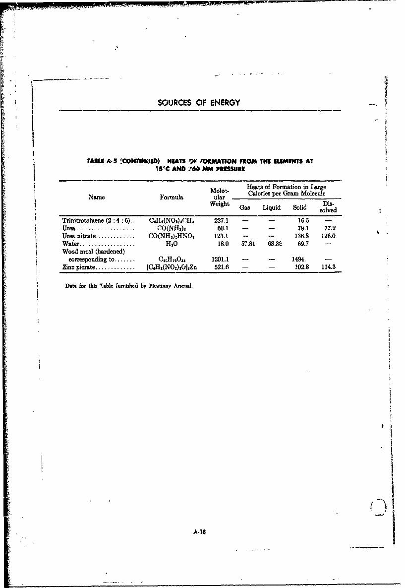
SOURCES OF ENERGY
TAMt &3 ,CONTIN0ED) HEATS OF IORMATION FROM THE ELEMENTS ATI5*C AND 760 MM PRESSURE
Moleci- Heats of Formation in Largeaular- Calories per Gram MoleculeName Foi-mula ular
Weight Gas Liquid Soli• Dis-solved
Trinitrotoluene (2 :4 :6).. CsH,(NO,)3CH3 227.1 - - 16.5 -Urea ................... CO(NH2)v 60.1 - - 79.1 77.2Urea nitrate ............. CO(NH2).HNO3 123.1 - - 136.8 126.0Waier .................. HIO 18.0 57.81 68.K 69.7 -
Wood mcal (hardened)corresponding to ....... CscHO2ss 1201.1 - - 1494. -
Zinc picrate ............. [CH•(NOs)3C]%Zn 521.6 - - 102.8 114.3
Data for this Table furnshed by Picatinny Arsenal.
A-18

INDEX
Alpha decay, 4-4 Composition A, 3-9
Aluminized explosives, 3-12 Composition B, 3-9
Amato], 3-3 Cordite N, 3-23
Ammonium picrate, 3-8 Co-volume, 2-2explosion of, 2-12 Criicality, 4-10
Atomic mass number, 4-2 increase of, 4-11Sstuctue, 4-2. Critical mass, 4-11weight, A-11
Average density, 1-7 Cross section, fission, 4-9
CyclotetramethylenetetranitramineAvogadros law, 2-6, 2-13 (see HMX)
Cyclotol, 3-9Bangalo:e torpedoes, 3-8
Cyclotrimethylenetrinitramine2yBeut decay, 4-4 (see RDX)Black powder, 3-14
Booster, M Decomposition of explosives, 3-5SBrisance, 1-8 lead azide, 3-6
relative, mercury fulminate, 3trinitrotoluene, 3-7
Burning action of smokeless powder, 3-17 Density, 2-2
Burning, controlled, 3-14 average, 1-7degressive, 3-17 impulse, 3-26neutral, 3-17 load, 1-7progressive, 3-17 of loading, 2-2relative areas, 3-1-7 ofadin, 2-2
Burning rates, measurement, A-8 high order of, 1-8
Burning time of smokeless powder, 3-15 low order of. 1-8velocity of, 1-7
Ballistic potential, 3-19 test for, A-4Ballistite, 3-24 Diglycol, 3-23Bursting 'charge explosive train, 1-11 Dynaites, 3-11
Cateorizaio ofexlsie, -Calorie, 24-3 Electron charge, 4-2jC ategorization of explosives, 1-8 l m n s s m o s -Chain reaction, 4-10 Elements', symbols, 4-3•i
Energy, equivalence with mass, 4-5Chamber pressure, actual. 2-15 nuclear, 4-8
Charge of nuclear particles, 4-4 Enthalpy, 2-4
Chemical explosive reactions, 1-1 Erosion of gun tube, 2-9
Chemical explosives, properties, 1-7 Expansion, work peformeA, 2-7 Ithaermochcmistry, 2-1.
Chemical kinetics, 1-5 Explosion, ammonium pierate, 2-12,
smokeless powder, 2-14 4,Chemicai reactions of expio.ives, 2-1 temperature, 2-9, 2-1i
I-i ,o

Explosive D, 3-8 Heat, evolution of, 1-2(see also Ammonium picrate) of formation, 2-3
Exrlosives, 3-1 at STP, A-15of carbon monoxide, 2-5aluminized,of nitroglycerin 2-5
categorization, o1-3f react n, 2-3characteristics, 3-Ichemical, 1-7 Heat capacity constants, 9,-11comparison, 3-4 Ldecomposition of Hi,'gh explosives, 1-3, 3-1
classes, 3-3I (see Decomposition cf exploeives) primary, 3-3, 3-5definition, 1-2 secondary, 3-3, 3-7high liquid, 3-11(see High explosives) liid 3-1 1
low load density of, 1-7
maiufacture, A-1 HMX, 3-10military, 3.1mixtures with metals, 3-12 Hygroscopicity, 1-7potential of, 2-3primary high, 3-3, S-5 Impulse, specific, 2-9p r o p e r t i e s o f , A -5 , A -6 I i i l a d f n l e q e r n i l f -reactions of Iiiladfnlsae rnil f
(see Reactions of explosives) Isotopes, 4-3secondary high, 3-3, 8-7 masses of, 4-8testing
(see Testing of explosives) Kilocalorie, 2-3Explosive trains, 1-9 Kinetics, chemical, 1-5
Fission, 4-7 Law or Avogaaro, 2-6, 2-13Fission cross section, 4-9 of Gay-Lussac, *2-7
Fission-fusion reactions, 4-1 Lead azide, 1-6, 3-6Flash, 3-21 Lead styphnate, 3-6Flash hider, 3-21 Lead trinitrorescorcinate, 3-6Flash suppressor, 3-22 Liquid high explosives, 3-11Fusion, 4-7 Load density, 1-7
Loading, density of, 2-2Gammas rays, 4-4 Low explosives, 1-3, 3-13Gases, densities, A-12 sensitivity, 3-14
formation, 1-2 stability, 3-14Gas liberated, volume, 2-6 Low order of detonation, 1-8
Gelignite, 3-11
Gram formula weight, 2-2 Mass, critical, 4-11equivalence of with energy, 4-5Gram molecale, 2-2 (f isotopes, 4-8
Gunpowder, 1-1 of nuclear particles, 4-3, 4-.7, 4-8Mean free path, 4-9
Half life, 4-8 Melting point, 3-4
1-2
_ _ .± ... . ... . . . . . . . . . . ... . .... . . . . . ... . ... . .- • .-- _ _ _ .- _ _' _ _ _ _ • _ . . . .. ... ...... . . .. .. . ... .. ... .. .. . ..... . . . ...... ... . ... . . . . .. .. . . ... ..... .. ... ... ... . .. . .... . .. ... .... . .. ...

Mercury fulminate, 1-6, 3-5 high-potential, 3-22
Metal-explosive mixtures, 34i2 hypergolic, 3-25improvements in, 3-21
Military explosives, 3-1 ionic, 0-27
Molecular specific heat, 2-2 liquid, 3-25
volume, 2-2 liquid qun, R_3.ametal-additive, 3.27nitroguanidine, 3-19
Neutron reaction, 4-10 perchlorate, A-3rocket. 3-2-1
Nitration, A-2 test'ng, A-8
Nitrocellulose, 3-18 single-base, 3-IS,(see also Single-base propellants)
Nitroglycerin, 1-5 solid, 3-24
Nobel, Alfred, 1-1 testing, A-8
Nuclear energy, 4-8 Propelling charge explosive brain, 1-9particle hag,4-4charge, Properties of explosives, 1-7, A-5
Pentolite, 3-10 Proton charge, 4-2
Perchlorate propellant, A-3 Radioactive serie., 4-5Perfect gas law, 2-7 Radioactivity, 4-4
PEI4N 3-10 RDX, 3-9Poly-base propellants, 3-19
(see also Propellants, double-base' Reacaon, heat of, 2-3
Potential, 2-4, 2-8 Reactions, fission-fusion, 4-1of an explosive, 2-3, 3-1 induced nuclear, 4-5of a , 3 , neutron, 4-10Se-twd- r back , 3-1 9 reacU. x .b "l 'es .... . a, " -1black, 3-14 decompos'.Cion prnducts, 1-9gun, 1-1 initiation of, 1.2smokeless, 3-15 :apidit of, 1-2
Powder grains, sizes, 3-lf1 with metals, 1-4shapes, 3-16 Rocket propellants, 3-23
Power of an e'xplosive, 1-8 physical testing, A-8Pressure, basic eroiiatiorei of, 2-12 Rockets, liquid propellant, 3-26
chamber, 2-15
Pressure determination at constant volume, -q 12 Sensi'civity of ex-losives, 1-7
"Pressure in propellant chamber, 2-13 108' explosive:,, 4to shock. A-4
Pressure of solid product formation, 2-14 to sh o p't A-1- ~Single-bas•e proeiliarnts, 3-18
Primer, 1-9 additives, A-3
Propellant chamber pressure, 2-13 manufacture, A-2
Propellants, 3-19 Smoke, 3-21composite, 3-°.24 Smokeless powder, burning action, 3-17double-base, 3-19 burning time, 3-15
•, exotic, 3-26exoto, 3-26 Solid propellants, testing. A-8
(fluoro, 32free radical, 3-27 Specific gravity, 2-2
1-3
. j- _ _ _ _ _ _

I wPrwrrrn',, rnz
-moleculiar, 2-2I ] variation with temperature, 2-10 letrvtoi, 5.8o'f solids and liquids, A-13 '"hlrvruochemistry of chemical explosives, 2,1
Specific impulse, 2-9, 3-24 TNT. 3-7Specific volume, 2-2 efficiency, 3-9
Stability of explosive, 1-p Tohtene, 1-6low explosive, 3-14 Torpedoes, bangalore, 3-8
j Standard state, 2-3 Trinitrotoluenc, 1-6, 3.7, 3.8
Strength, 1-8 manufacture, A-1j Structure. atomic, 4-2
Uranium series, 4-6
Temperature of decomposition, L-9of explosion, 2-9, 2-11 Velocity of detonation, 1-7of solid product formation, _-" N2 test for, A 4 Iof storage, 1-9
Volume, molecular, 2-2:Testing of explosives, A-I, A-4 specific, 2-2
ballistic mortar, A-7 4explosive train tests, A-8 We' thickness, 3-16, 3-17fragmentation tests, A-8 t srelative brisanc-, A4 WVeight, atomic, A-11sensitivity to shock, A-4 Work, 2-8setback tests, A-8 (see also Potential)trauzl lead blocks, A4, A-7velocitv of detonation, A-4 Work determination in dynamic system, 2-15
Tetranitroaniline, 3-13 Work performed in expansion, 2-7
-1-4
VO
j 1.
"" V ?g PZ•rS FII 14 -I-)
$I

UNCLASSIFIED
AD NUMBER
AD830287
NEW LIMITATION CHANGE
TOApproved for public release, distributionunlimited
FROMDistribution authorized to U.S. Gov't.agencies and their contractors;Administrative/Operational Use; Sep 1963.Other requests shall be referred to HQ,U.S. Army Materiel Command, Washington,DC.
AUTHORITY
USAMC ltr, 2 Jul 1973
THIS PAGE IS UNCLASSIFIED
AM . PAMPHLET AMCP 106-107THIS IS A REPRINTWITHOUTCHANGF OF OROP20-107
J RESEARCH AND DEVELOPMENTOF MATERIEL
ENGINEERING DESIGN HANDBOOK
ELEMENTS OF ARMAMENT ENGINEERINGPART TWO
1) BALLISTICS
li gu-E Li÷'••DDC,
IsI L~~tt
"*li'.• .tI i, :V .-'2 1
.. .- !t~i f~tl• I)oC
!•IEADQUARTERS, U. S. ARMY MATERIEL COMMAND SEPTEMBER 1963
Il' wJIiv. $ CiO ~l •.
S ..- 'HEADQUAR FERSUNtITED STTATES AR.MY MATERIEL COYMMAND
ir. V WASHINGT ON 25, D.C.
1 •30 September 1963
A.MCP 70o-107, Elements oi Armamenta ngineering, Part Two,Ballistics. forming part of the Army Materiel Command EngineeringDe'-gn Handbook Series, is published for the information and guidanceof all concerned.,
FOR THE CC,'-lANDZFR:
SELWYN D. SMITH, JR.Major General, USAChief of Staff
OI"FiCIAL :
R. 0. DAVTDSkN
Colonel, GS
Chief, Admi istrative Office
DISTRIBUTION: Special
.4)

ELEMENTS OF ARMAMENT ENGINEERING
PART 2, BALLISTICS
•..
k 4
4i. "

FOREWORD
This is one of a group of handbooks covering the scope of a number of proposed handbooksthe engineering information and quantitative to include the information. For further infor-
S. data needed in the design and construction of marion and more complete lists of references theordnancL, equipment, which (as a group) con- reader is referred to other appropriate hand-stitutes the Ordnance Engineering Design Hand- books within the Series.book Series. Arrangement for publication of the handbooks
The three handbooks comprising "Elements comprising "Elements of Armament Engineer-Sof Armament Engineering" were produced from ing" was made under the direction of the
text material prepared for use at the United Ordnance Engineering Handbook Office, DukeStates Military Academy. They are published University, under contract to the Office of Ord-as part of the Handbook Series to make generally nance Research. The copy was prepared by the
Savailable the wealth of fundamental information McGraw-Hill Book Company, under subcontractcontained in the text material, which is of value to the Ordnance Engineering Handbook Office."to those concerned with ordnance design, par-ticularly to new engineers and to contractors'personnel. Publication of this material in its
* existing form avoids the necessity of extending
tg
I> .
I
i.u
r
FOREWORD TO ORIGINALTEXT MATERIAL
I his text has been prepared to meet a specific development and changes in the field of wea-requirement as a reference for instruction in pons design."Elements of Armament Engineering," a one- References cited are those availab~e to thesemester course in applied engineering analysis student as 'he resalt of study in previous coursesconducted by the Department of Ordnance at at the United States Military Academy. Advancedthe United States Military Academy, for mem- references are available at the Department ofbers of the First (Senior) Class. It represents the Ordnance Reference Room.application of military, scientific, and engineer-ing fundamentals to the analysis, design and op- Contributing authors for 1958-59 revision are:eration of weapons systems, including nuclearcomponnts. It is not intended to fully or'ent Maj. W. E. Rafert, Ord Corps, Asst Professoror familiarize the student in weapons employ- Capt. A. W. Jank, Ord Corps, Instructorment or nomerclature. Capt. C. M. Jaco, Jr., Ord Corps, Instructor
Of necessity, the large volume of classified Capt. J. M. Cragin, Ord Corps, - -- Istructor.data used in presentation of this course has been Capt. G. K. Patterson, USAF, Instructoromitted; hence the text is intended to serve as apoint of departure for classroom discussions. The JOHN D. BILLINGSLEYtext is revised annually by instructors of the Colonel, U. S. ArmyDepartment of Ordnance in an effort to assure Professor of Ordnancethat subject presentation will keep pace with August, 1958
I
I|¥lv.
-J
PREFACE
The science of ballistics involves the study of the motion of projectiles as a particular branch ofapplied mechanics and related fields of physics, chemistry, mathematics, and engineering. It in-cludes, within its scope, the natural division of this science into the subjects of interior ballistics,the metion of a projectile or missile while under the influence of a gun or thrust propulsion device;exterior ballistics, the projectile -*r missile in flight; and terminal ballistics, its effectiveness in de-feating a target. With each successive performance dependent on that preceding, the overall bal-listic performance of any missile or projectile must consist of reliable and reproducible actions ineach of these phases despite conflicting design requirements in certain areas.
I' Ballistics produces a rational foundation for the design and development of armam t materiel.Therefore, a concept of the basis for the design of weapons or development of arnmunititba cannotbe realized withcut a basic understanding of this science. The following chapters presentinforma-tion about each phaseof ballistics to the extent believed necessary to pursue a study of the designand-engThiiiering analysis of components of weapon systems which satisfy the basic requirements oflaunch, flight, and terminal effects. Such problems are presented in Part 3 (Weapon Systems andComponents) of this text.
V
'Ii

BLANK PAGEt
9!
* - *1
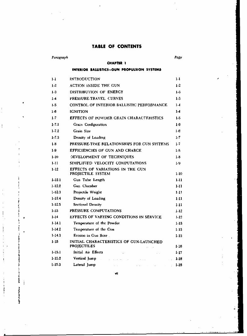
TABLE OF CONTENTS
Paragraph Page
CHAPTER I
INTERIOR BALLISTICS-GUN PROPULSION SYSTEMS
1-1 INTRODUCTION 1-1
1-2 ACTION INSIDE THE GUN 1-2
1-3 DISTRIBUTION OF ENERGY 1-3
1-4 PRESSURE-TRAVEL CURVES 1-3
1-5 CONTROL OF INTERIOR BALLISTIC PERFORMANCE 1-4
1-6 IGNITION 1-4
1-7 EFFECTS OF POWDER GRAIN CHARACTERISTICS 1-5
1-7.1 Grain Configuration 1-6
1-7.2 Grain Size 1-6
1-7.3 Density of Loading 1-7
1-8 PRESSURE-TIME RELATIONSHIPS FOR GUN SYSTEMS 1-7
1-9 EFFICIENCIES OF GUN AND CHARGE 1-8
1-10 OEVELOPMENT OF TECHNIQUES 1-8
1-11 SIMPLIFIFD VELOCITY COMPUTATIONS 1-9
1-12 EFFECTS OF VARIATIONS IN THE GUNPROJECTILE SYSTEM 1-10
1-12.1 Gun Tube Length 1-11
1-12.2 Gun Chamber 1-11
1-12.3 Projectile Weight 1-1!
1-12.4 Density of Loading 1-11
1-12.5 Sectional Density 1-11
1-13 PRESSURE COMPUTATIONS 1-12
1-14 EFFECTS OF VARYING CONDITIONS IN SERVICE 1-12
1-14.1 Temperature of the Powder 1-13
1-14.2 Temperature of the Gun 1-13
1-14.3 Erosion in Gun Bore 1-13
"1-15 INITIAL CHARACTERISTICS OF GUN-LAUNCHEDPROJECTILES 1-16
1-15.1 Initial Air Effects 1-17
1-15.2 Vertical jump 1-18
1-15.3 Lateral Jump 1-18
& vii
L
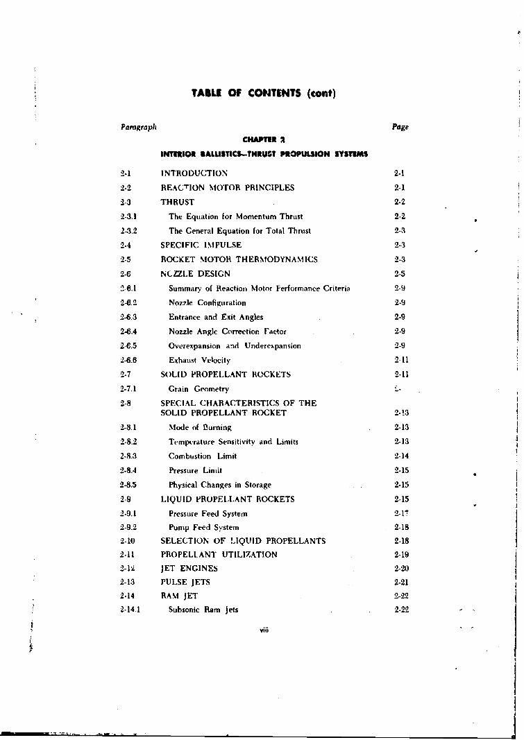
TABLE OF CONTENTS (cont)
Paragraph Page
CHAPTIR 2
INTERIOR SALUSTICS-THRUST PROPULSION SYST1MS
2.1 INTRODUCTION 2-1
2-2 REACTION MOTOR PRINCIPLES 2-1
2-3 THRUST 2-2
2-3.1 The Equation for Momentum Thrust 2-2
242 The General Equation for Total Thrust 2-3
2-4 SPECIFIC IMPULSE 2-3
2-5 ROCKET MOTOR THERMODYNAMICS 2-3
2-6 NLCTLE DESIGN 2-5
2-6.1 Summarv of Reaction Motor Performance Criteria 2-9
2-6.2 Nozzle Configuration 2-9
2-6.3 Entrance and Exit Angles 2-9
2.0.4 Nozzle Angle Correction I'actor 2-9
2-6.5 Overexpansion and Underexpansion 2-9
2-6.6 Exhaust Velocity 2-11
2-7 SOLID PROPELLANT ROCKETS 2-11
2-7.1 Grain Geometry -
2-8 SPECIAL CHARACTERISTICS OF THESOLID PROPELLANT ROCKET 2-13
2-8.1 Mode of Burning 2-13
2-8.2 Templrature Sensitivity and Limits 2-13
2-8.3 Combustion Limit 2-14
2-8.4 Pressure Limit 2-15
2-8.5 Physical Changes in Storage 2-15
2-9 LIQUID PROPELLANT ROCKETS 2-15
2-9.1 Pressure Feed System 2-17
2-9.2 Pump Feed System 2-18
2-10 SELECTION OF LIQUID PROPELLANTS 2-18
2-11 PROPELLANT UTILIZATION 2-19
2-4' JET ENGINES 2-20
2-13 PULSE JETS 2-21
2-14 RAM JET 2-22
2-14.1 Subsonic Ram jets 2-22
viiii-
4
TA3LE OF CONTENTS (cont)
Parugraph Page
Chapter 2 (cout)
2.14.2 S.zpurinic Ram jets 2-23
2-15 TURIBO JET 2-24
2-16 SUMMARY OF REACTION MOTORS 2-27
CHAPTER 3
EXTERIOR BALLISTICS
:3-1 INTRODUCTION 5-1
3-2 DESCRIPTION OF A TRAJECTORY 3-3
:3-3 AERODYNAMIC FORCES ACTING ONTHE PROJECTILE 3-4
3-3.1 Drag 3-5
•3-3.2 Crosswind Force 3-5
.3-3:3 Overturning Moment 3-6
3-3.4 Magnus Force 3-6
.3-3.5 Magnus Moment 3-6
:3-.b Yawing Moment Due to Yawing 3-6
3-3.7 Rolling Moment 3-6
3-4 EVALUATION OF PRINCIPLE AND MOMENTS 3-6
:3-4-1 Projectile Form 3-7
.3-4.2 Drag Coefficient 3-7
3-5 IIALLISTIC COEFFICIENT 3-8
3-6 BoLLISTIC TABLES AND FIRING TABLES 3-9
3-7 TRAJECTORY ANALYSIS 3-10
.3-8 BALLISTIC COEFFICIENTS FOR RO'._BS 3-11
.f 3-9 TYPICAL BOMBING PROBL."M 3-14
j 3-9.1 Vertical Travel 3-15
3 3-9.2 Linear Travel 3-15
.3-9.3 Trail 3-15
£ 3-9.4 Cross Trail 3-15
3.10 SPECIALIZED BOMBING TECHNIQUES 3-15
:3-li STABILIZATION C!- PROJECTILES 3-16
3-11.1 Fin Stabilization 3-16I-x -I3 Ix '
I

TABLE OF CONTENTS (cont)
Peragraph Page
Chapter 3 (cant)
3-11.2 Roll Stabilization 3-17
3-11.3 Spin Stabilization 3-17
3-11 STABILITY AND DRIFT FOR SPINSTABILIZED PROJECTILES 3-19
CHAPTER 4
SALLISTIC AND AERODYNAMIC TRAJECTORILI
4-1 INTRODUCTION 4-1
4-1.1 Ballistic Missiles 4-1
4-1.2 Aerodynamic Missiles 4-1
4-1.3 Hypervelocity Vehicles 4-1
4-2 BALLISTIC MISSILES 4-2
4-3 SYSTEMS AND SUBSYSTEMS OF A LONG-RANGEBALLISTIC MISSILE 4-3
4-4 POWERED FLIGHT OF THE N4ISSILE 4-6
4-5 EXTERIOR BALLISTICS OF A MISSILE 4-7
4-6 EFFECT OF EARTH'S SPIN AND CURVATUREON TRAJECTORY LENGTH 4-7
4-7 THEORY OF BALLISTIC TRAJECTORIE3 4-9
4-8 SUMN.ARY OF EARTH SATELLITE VEHICLES 4-10
4-9 AERODYNAMIC MISSILE CONFIGURATION 4-12
4-9.1 Profile Shapes 4-15
4-9.2 Plan Forms 4-15
CHAPTER 5
GUIDANCE FOR CONTROLLED TRAJECTORIES
5-1 GENERAL r1
5-2 ATTITUDE CONTROL 5-1
5-3 PATH CONTROL 5-2
5-4 GUIDANCE FOR PREDETERMINED TRAJECTORIES 5-3
5-4 1 ___ _ . ,v5yCm 5-3
5-4.2 Terrestrial Reference Guidance Systems 5-4
5-4.3 Radio Navigation Guidance Systems 5-4
5-4.4 Celestial Navigation Guidance System 5-6
x
TAKiE OF CONTENTS (cent)
Paragraph Pap
Chapeer S (coot)
545 Inertial Guidance System 57
5-5 GUIDANCE FOR CHANGING TRAJECTORIES 5-8
5S5.1 Command Guidance System 5-8
5-5.2 Beam Rider 5-9
5-5.3 Homing (Terminal Guidance) 5-10
5-8 KINEMATICS OF INTERCEPT COURSES 5-13
CNHAmM 6
INFODU0CTION TO TRMINL SALWSTICS
6-1 SCOPE . ... .. .... ..
6-2 DEVELOPMENT AND USE OF TERMIN, 4L BALLIS'ICS 6-1
6-3 TECHNIQUES OF TERMIINAL BALLISTIC STUDIES 6-1
6-4 MEANS OF PRODUCINg, DAMAGE 8-36-5 TARGET ANALYSIS ... .6-3
6-6 PROBABILATY AND STATISTICAL TREATMENTOF BALLISTICS 84
6-6.1 Introduction .84
6-6.2 Probability 6-4
6.0.5 Statistics . .
6-7 PROBABILITY OF A SUCCESSFUL MISSION
6-8 DAMAGE DISTRIBUTION FOR LARGE YIELDWEAPONS 0-8
6-9 THE DAMAGE FUNCTION 6-9
6-10 FACTORS REGULATING OVERALL SYSTEM ERRORS 0-9
6 10.! General 6-9
6-10.2 Factors Considered 6-9
6-10.3 Point Targets 6-10
6-10.4 Area Target Considerations 6-13
6-11 THE P(f) RELATIONSHIP FOR CIRCULAR TArGETS,NON-ZERO CEP 6-15
612 IRREGULAR TARGETS 6-15
xl
TABLE OF CONTENTS (cont)
'aragralph Page
CHAPTER 7
FRAGMENTATION
7-1 INTRODUCTION 7-1
7-2 NATURE OF THE FRAGMENTATION PROCESS 7-1
7-3 BALLISTICS OF FRAGMENTS 7-1
7-4 INITIAL VELOCITIES OF FRAGMENTS 7-4
7-5 DIRECTION OF FRAGMENT FLIGHT 7-5
7-6 NUMBER. TYPE, AND SIZE OF FRAGMENTS 7-5
7-7 FRAGMENT DAMAGE 7-7
7-8 SHELL FRAGMENT DAMAGE 7-12
7-9 CONTROLLED FRAGMENTATION 7-12
7-9.1 Direction of Flight 7.12
7-9.2 Velocity 7-12
CHAPTER 5
ILAST EFFECTS BY CHIMICAL AND ATOMIC EXPLOSIONS
8-1 MECHANICS OF BLAST 8-1
8-2 PEAK OVERPRESSURE 8-3
8-3 THE EFFECT OF MACH REFLECTION ON AIR BURST 8-5
8-4 IMPULSE 8-6
8-5 DYNAMIC PRESSURE 8-8
8-6 AIR BLAST LOADING 8-9
8-7 DIFFRACTION LOADING 8-9
8-8 DRAG (DYNAMIC PRESSURE) LOADING 8-10
8-9 TECHNICAL ASPECTS OF BLAST WAVE PHENOMENA 8-10
8-10 ALTITUDE CORRECTIONS 8-12
8-11 BLAST EFFECTS FROM NUCLEAR WEAPONS 8-12
8-11.1 Personnel 8-12
8-11.2 Military Equipment 8-12
8-11.3 Structures 8-18
8-11.4 Craterh.g 8............8-13
xil
ATABLE OF CONTENTS (ont).
Paragraph Page•
CHAPTER 9
THERMAL AiD NUCLAA EFFECTS OF ATOMIC DErTONATIONS
9-1 INTRODUCTION 9-1
9-2 UNDERGROUND BURST ............. 9-2
9-3 SURFACE BURST 9-!Z
9-4 BURSTS IN OR OVER WATER 9-3
9-5 CHARACTERISTICS OF THERMAL RADIATION ....... 9-8
9-6 MEUHANISM OF THERMAL RAIAATION ............... 9-3
9-7 ATTENUATION OF THERMAL RADIATION ..... 94
S9-8 ABSORPTION OF THERMAL RADIATION 5...... ... 9-
r 9-9 BURN INJURY ENERGIES AND RANGES. 9-6
9-10 EFFECTIVENESS OF SECOND RADIATION PULSE 9-6
9-11 CHARACTERISTICS OF NUCLEAR RADIATION .... 9-8
9-12 INITIAL GAMMA RADIATION .. ..... ....... 9-9
9-13 SOURCES OF NEUTRONS AND IONIZATIONCHARACTERISTICS .. .................. 9-10
9-14 NUCLEAR RADIATION EFFECTS 9-11
9-15 RESIDUAL RADIATION ................ ... 9-12
9-16 NEUTRON INDUCED ACTIVITY 9-12
9-17 FALLOUT ... ... . . 9-13
9-18 LONG-TERM RESIDUAL RADIATION HAZARD 9-45
CHAPTER 10
BALUSTIC ATTACK OF ARMOR USING KINETIC ANDCHEMICAL ENERGY EFFECTS .
10-1 GENERAL ...........
10-2 TYPES OF ARMOR MATERIALS 10-1
10-2.1 Rolled Homogeneous Steel Armor ................. 10-1
10-2.2 Cast Homogeneous Steel Armor 10-110-2.3 Face-Hardened Steel Armor "10-10-2.4 Nonferrous Armor Materials ............. . 10-4
10-3 SURFACE DESIGN .... ... ......... . .. 10-4
10-4 FABRICATION OF MOBILE ARMOR STRUCTURES 10-4Ii
xiii -
LV| r: .~- - - - . - -A ¶ fl ... Z. .C~ S ~ L
TABLE OF CONTENTS (:ont)
Paragraph Page
Chapter 10 (cont)
10-5 INNOVATIONS 10-5
10-5.1 Spaced Armor 10-6
10-5.2 Laminated Armor 10-6
10-5.3 Composite Armor 10-6
10-6 NECESSARY BALLISTIC PROPERTIES OF ARMOR 10-6
10-6.1 Resistance to Penetration 10-7
10-6.2 Resistance to Shock 10-7
10"6.3 Resistance to Spalling 10-7
10-7 EFFECTS OF OBLIQUITY AND HARDNESS ONPERFORMANCE OF ARMOR 10-7
10-7.1 Effect of Obliquity Upon Resistance to Penetration 10-7
10-7.2 Effect of Hardness Upon Resistance to Penetration 10-10
10-7.3 Discussion 10-11
10-8 KINETIC ENERGY PROJECTILES 10-11
10-8.1 Definition of Terms 10-11
10-9 GENERAL EFFECTS OF IMPACT-PROJECTILE DEFORMATION 10-14
10-10 EFFECT OF PROJECTILE DEFORMATION ONPERFORATING ABIL!TY 10-17
10-11 MECHANISM OF ARMOR PENETRATION-PLATE DEFORMATION 10-18
10-11.1 The Elastic Response 10-19
10-11.2 The Plastic Response 10-19
10-12 CAUSES OF SHATTER: MEANS OF PREVENTINGSHATTER 10-19
10-13 COMPARATIVE PERFORMANCE OF CAPPED (APC)AND MONOBLOC (AP) PROJECTILES 10-20
10-14 PERFORMANCE OF JACKETED PROJECTILES 10.22
10-14.1 Composite Rigid Type 10-22
10-14.2 Folding Skirt Projectiles (Tapered Bore) 10-23
10- L4.3 Discarding Sabot 10-23
10-15 OVERALL COMPARISON OF ARMOR PIERCINGPROJECTILES 10-23
10-16 CHEMICAL ENERGY PROJECTILES 10-24
xlv
TABLE OF CONTENTS (cont)
Paragraph Page
Chapter 10 (cont)
10-16.1 History 10-24
10-17 THE SHAPED CHARGE PRINCIPLE 10-24
10-17.1 Functionirg 10-25
10-18 THE THEORY OF JET PENETRATION 10-25
10-19 FACTORS AFFECTING PENETRATION BY SHAPEDCHARGE PROJECTILES 16-28
10-19.1 Type, Density, and Rate of Detonation ot ExplosiveCharge 10-28
10-19.2 Confinement of Charge ..... ... 10-28
10-19.3 Diameter and Length of Charge Back of Liner 10-28
10-19.4 Liner Material and Thickness 10-28
10-19.5 Included Angle of Liner ... 10-29
10-19.6 Liner Shape 10-29
10-19.7 Rotation of the Missile 10-29
10-19.8 Angle of Impact 10-29
10-19.9 Standoff Distance 10-29
10-19.10 Design and Manufacturing Problems 10-,30
10-20 PERFORMANCE OF SHAPED CHARGE MISSILES 10-30
10-21 HIGH EXPLOSIVE PLASTIC PROJECTILES 10-31
10-22 BODY ARMOR 10-31
APPENDIX A
INSTRUMENTATION
A-I INTRODUCTION A-i
A-2 TELEMETRY A-2
A-3 VELOCITY MEASUREMENTS A-4
A-4 TIME RECORDING DEVICES A-5
A-4.1 Aberdeen Chronograph A-7
A-4.2 Camera Chronograph (Solenoid) A-7
A-4.3 Machine Gun Chronograph A-7A-5 FIELD CHRONOGRAPH A-7
A-6 PRESSURE MEASUREMENTS A-8
xv
I4TABLE OF CONTENTS (cont)
Paragraph Page
APPENDIX A (mast)
A-6.1 Crusher Gauges A-8
A-6.2 Piezoelectric Pressure Gauges ......... A-8
A-6.3 Strain Gauges A-10
A-7 RECORDING OF PRESSURE OR STRAINMEASUREMENTS A-I1
A-8 PHOTOGRAPHIC MEASUREMENTS .. A....l. A-
A-8.1 Microflash A-il
A-8.2 High Speed Photography A-1l
A-8.3 Askania Theodolites, Ballistic, Mitchell, and Bowen-KnappCameras A-11
A-8.4 Schlieren Photography A-16
A-8.5 X-ray Photography A-16
A-8.6 Spark Photography ....... A-I0
APPENDIX 8
BALLIS1C ATTACK OF CONCRETE BY USING KINETICT4NERGY AND CHEMICAL ENERGY EFFECTS
B-1 INTIRODUCTION .......... B-I
B-2 DEFINITIONS ....... BA
B-3 BACKGROUND B-I
B-4 GENERAL EFFECTS OF INERT IMPACT B-2
B-5 GENERAL EFFECTS OF HIGH EXPLQSIVE IMPACT B-3
B-6 SOLUTION TO THE PROBLEM OF PE6RFORATION OFTHICK REINFORCED CONCRETE B-3
B-7 PROBLEMS OF EMPLOYMENT B4
B-8 EFFECT OF THE SHAPED CHARGF AGAINSTCONCRETE B-6
INDEX 1-1
xvi
* -
:1
LIST OF ILLUSTRATIONS
Fig. No. Tare Page
1-1 Standard gun system 1.2
1-2 Recoilless system 1-2
1-.3 Piessure-travel (solid lines) and velocity-travel (dottedlines) curves 1-3
1-4 Pressure-travel relationship 1-0
1-5 Effects of grain configuration on pressure-travel curves.tCharge weight is equal in each case) 1-7
T11-6 Effects of independently varying grain size. (Charge
weight is equal in each cast) .. ... 1-7
1-7 Piessure-time relationships determined experimentally ...... 1-8
1-8 LeDuc velocity-travel relationship 1-9
1-9 Advanced gas erosion at origin of rifling near 12 o'clock of155-:nm gun, M2. Note complete obliteration of lands(Extract TB9-1960-2) 1-14
1-10 Impressions shu ving scoring at 12 o'clock (top) and gaserosion at 6 o'clock (bottom). Bottom alse shows light scor-ing in the groove'. Taken from 155-mm gun, M2(Extract TB 9-1860-2) 1-14
1-11 Muzzle velocity loss as a function of bore measurement for
4 " tubes used in 90-mm guns M1, M2, and MS(Extract TB 9-1860-2) 1-15
1-12 Remaining life as a function of bore measurement for tubesused in 90-mm guns MI, M2, and MN1(Extract TB 9-1860.2) 1-16
1-13(1) Effects of projectile emerging from muzzle. (Spark photo-graph of gun being fired) 1-18
(2) Effects of projectile emerging from muzzle. (Spark photo-graph of gun being fired) ........ 1-19
(3) Effects of projectile emerging from muzzle. (Spark photo-graph of gun being fired) ...... 1-19
2-1 Reaction motor with convergent-divergent nozzle 2-2 -
2-2 Schematic flow diagram 2-4 k'
2-3 Distance along nozzle 2-7&i2-4 The distribution of pressure, density, temperature, and
velocity along the nozzle 2-8r-ilxvii ,
Ii:I
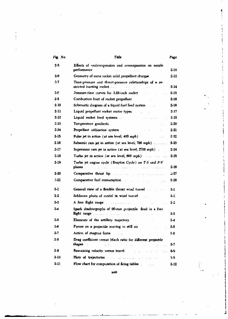
Fig. No. Title Page
2-5 Effects of -inderexpansion and overexpansion on nozzleperformance 2-10
2-6 Geometry of some rocket solid propellant charges 2-12
17-7 Time-pressure and thrust-pressure relationships of a re-stricted burning rocket 2-14
2-F Pressure-time curves for 3.25-inch rocket 2-15
2-9 Combustion limit of rocket propellant 2-16
2-10 Scheraatic diagram of a liquid fuel feed system 2.16
2-11 Liquid propellant rocket motor types 2-17
2.12 Liquid rocket feed systems 2.18
2-13 Temperature gradients 2-20
2-14 Propellant utilization system 2-21
2-15 Pulse jet in action (at sea level, 400 mph) 222
2-16 Subsonic ram jet in action (at sea levei, 700 mph) 2-23
2-17 Supersonic ram jet in action (at sea level, 2700 mph) 2-24
2-18 Turbo jet in action (at sea level, 600 mph) 2-25
2-19 Turbo jet engine cycle (Brayton Cycle) on T-S and P-Vplanes 2-26
2-20 Comparative thrust hp .-27
2-21 Comparative fuel consumption 2-28
3-1 General view of a flexible throat wind btnnel 3-1
3-2 Schhleren photo of model in wind tunnel 3-2
3-3 A free flight range 3-2
3-4 Spark shadowgraphs of 90.mm projectile fired in a freeflight range ... ... 3-3
3-5 Elements of the artillery trajectory 3-4
3-6 Forces on a projectile moving in still air 3-5
3-7 Action of magnus force 3-8
3-8 Drag coefficient versus Mach ratio for different projectileshapes 3-7
3-9 Remaining velocity versus travel 3-9
3-10 Plots of trajectories .3-9
3-11 Flow chart for computation of firing tables 3-12
XVlii
I | - - -. . .._ ... . . . . . . .. ... . .
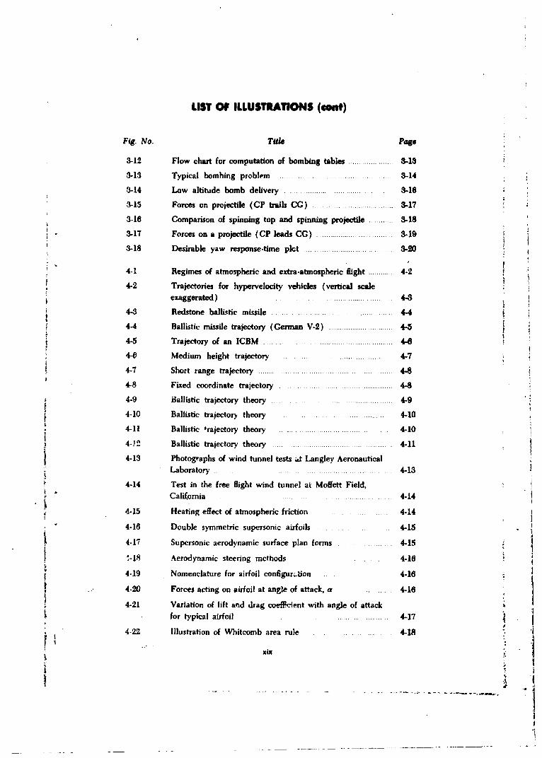
LIST OF ILLUSTRATIONS (€ont)
Fig. No. Tale Page
3-12 Flow chart for computation of bombing tables ...................... 3.18
3-13 Typical bombing problem ........ 3-14
3-14 Low altitude bomb delivery 3-16
3-15 Forces on projectile (CP trails CC) ..... ................ .... 3-17
3-16 Comparison of spinning top and spinning projectile ........... 3-18
3-17 Forces on a projectile (CP leads CC) ............................... .. 3-19
3-18 Desirable yaw response-time pkct .... .............. 3-20
4-1 Regimes of atmospheric and extra-atmospheric flight ........... 4-2
4-2 Trajectories for hypervelocity vehicles (vertical scale
exaggerated) .... .............. 4-3
4-3 Redstone ballictic m issile ......... ............ . .............. 4-4
4-4 Ballistic missile trajectory (Cerman V-2) ............................. 4-5
4-5 Trajectory of an ICBM .... ... ..... ............ .......... 4-6
4-0 Medium height trajectory ............. ............. .. 4-7
4-7 Short range trajectory ....... ............................... ...... 4-8
4-8 Fixed coordinate trajectory ................. -8
4-9 Ballistic trajectory theory . .... .................... 4-9
4-10 Ballistic trajectory theory ........ ................. .... 4-10
4-11 Ballistic trajectory theory . . ......................... 4-10
4-J2 Ballistic trajectory theory ......... 4-11
4-13 Photographs of wind tunnel tests at Langley AeronauticalLaboratory .... .... .. .. 4-13
4-14 Test in the free flight wind tunnel at Moffett Field,California .... ... ..... ........ 4-14
4-15 Heating effect of atmospheric friction .... ... 4-14
4-16 Double symmetric supersonic airfoils 4-15
4-17 Supersonic aerodynamic surface plan forms 4-15
"-18 Aerodynamic steering methods ..... 4-16
4-19 Nomenclature for airfoil configura.tion 4-16I 4-20 Forces acting on airfoil at angle of attack, a ......... 4-16
4-21 Variation of lift and drag coefficient with angle of attack* for typical airfoil 4-17
4-22 Illustration of Whitcomb area rule 4-18
xix
J !~.-.-. -- -- ,-
. -I

LIST OF ILLUSTRATIONS (cont)
Fig. No. Title Page
5-1 Guidance systems 5-1
5-2 Y^w, pitch, and roll axes 5.2
5-1 Complete missile guidance system 5-3
5-4 Radio navigation paths 5-5
5-5 Hyperbolic grid 5-6
5-6 Schematic of celestial navigation guidance 5-7
5-7 Sohematic of inertial guidance sytem 5-8
5-8 Command guidance system 5-9
5-9 Single-beam rider 5-10
5-10 Dual-beam rider 5-10
5-11 Active homing 5-11
5-12 Passive homing guidance 5-12
5V-13 Semi-active homing guidance 5-12
5-14 Ceomnety, of intercept problem 5-14
5-15 Conditions for finite turning rate (deviated pursuit) 5-16
e-1 Bursting shell 6-2
6-2 Shock tube 6-3
3-3 Damage functions for two different sets of conditions 6-9
6.4 Point targe" chart, average variability 6-11
6-5 Extension chart, point targets 6-12
6-6 Two typical P(f) curves 6-13
6-7 P( .) nomograph, average variability 6-14
7-1 Detonation of a 20-mim shell 7-2
7-2 Static nose-down detonation of a bomb 7-5
7-3 Fragments from bomb, fragmentation, 220D-b, AN-MS8 7-6
7-4 Damage pattern: bomb. GP .. 7-9
7-5 Damage pattern: bomb, GP 7-9
7-fl Casualties versuf height of burst bomb, fragmentation 7-10
7.7 Shell density in area fire; superquick ground burst, 155-mmH.E. shell, M107 7-13
7-8 ExperimCrtal grooved ring shell body 7-14
7-9 Uniform fragments obtained 'rom grooved ring shell body '-14
xx

IiLIST OF ILLUSTRATIONS (cont)
Fig. No. Title Pager
7-10 Uniform spacing of perforations in 5/16-inch steel plateobtained by grooved ring shell 7-15
7-11 Detonation of grooved rii.g shell 7.18
7-12 Hand grenade 7-17
8-1 Profile of a blast wave at a particular distance from pointof detonation 8-1
8-2 Schematic representation of bomb explosion 8-2
8-3 Peak blast pressure versus distance from bomb burst 8-4
g 8.4 Formation of Mach wave and triple point 8-8
8-5 Blast impulse versus distance from bomb burst 8-7 -
8-6 Variation of overpressure and dynamic pressure w'ith timeat a fixed location 8-8
8-7 Stages in the diffraction of a blast wave by a structure 8-10
8-8 Relation of blast wave characteristics at the shock front 8-11
9-1 Air burst of atomic bomb (20-KT) 9-1
9-2 Emission of thermal radiation in two pulses 9-4
)9-3 Distances at which burns occur on bare skin 9-7
9-4 Fallout from a high yield surface burst weapon 9-14
10-1 Armored infantry vehicle, nght side view 10-2
10-2 90-mm gun tank, M48 ........... 10-31 10-3 Reentrant angle effect 10-5
10-4 Formation of petalling and plugging as a result ofpenetration 10-8
10-5 Failure of a 1i-inch cast armor plate resulting from shockof impact during low temperature tests ...... 10-10
o 10-6 Formation of spall in armor 10-12
10-7 Resistance to penetration versus hardness 10-14
10-8 Views of projectile exit regions 10-15
10-9 Striking angle or angle of incidence ............ 10-15
10-10 Perforation above shatter velocity (top) and below shatter"velocity (bottom) 10-16
10-11 Effect of striking angle on shatter of projectile 10-17
10-12 Effect of striking velocity on shatter of projectile .......... 10-17 I10-13 Effect of shatter on perforation 10-18 2
xxi
b'

LIST OF ILLUSTRATIONS (cont)
Fig. No. Title Page
10-14 Effect of yaw angle on shatter of projectile 10-20
10.15 Effect of plugging action on shatter o'f projectile 10-20
10-16 Effect of compressive forces on shatter of projectile 10-20
10-17 Projectile types 10-21
10-18 Shaped charge (high explosive, antitank shell) 10-25
10-19 Ultra high speed radiograph of shaped charge detonation(jet moves from right to left) 10-26
10-20 Jet penetration 10-27
10-21 Dependence of penetration on standoff distance 10-27
A-I Schematic telemetering system A-3
A-2 Pick-up coils for counter chronograph A-4
A-3 Views of -sky scre, a showing aligning telescope and mount A-5
A-4 Schematic diagram of lumiline screens and counterchronograph A-6
A-5 Schematic diagram of Aberdeen Chronograph A-6
A-6 Exploded vicw of a crusher gauge A-8
A-7 Piezoelectric pressure gauge A-9
A-8 Piezoelectric pressure gauge for measuring pressures up to80,000 psi A-9
A-9 Mounting of resistance strain gauges on a gun tube A-10
A-10 Pressure strain gauge, assembled (top) and disassembled(bottom) A-10
A-11 Cathode ray oscillogram of prcssure-time history for anartillery piece A-11
A-i2 Askania cine-theodolite A-12
A-13 Askan~a cine-theodolite record of A-4 (V-2) missile A-12
A-14 M;tche!l photo theodolite A-13
A-15 Mitchell photo theodolite record of A-4 missile A-13
A-I8 Bowen-Knapp camera A-14
A-17 Bowen-Knapp record of A-4 missile at intervals ofone-thirtieth of a second, showing referency system A-14
A-18 Twin 4.5-inch tracking telescopes A-15
A-19 4.5-Inch tracking telescope record of A-4 missile A-15
B-I Comlparison of inert impact against armor and concrete B-2
xxii
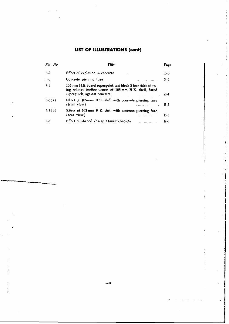
LIST OF ILLUSTRATIONS (cont)
Fig. No. Title Page
B-2 Effect of explosion in concrete B-3
B-3 Concrete piercing fuze B4
9-4 105-mm H.E. fuzed superquick test block 3 feet thick show-ing relative ineffectiveness of 105-mm H.E. shell, fuzedsuperquick, against concrete B-4
B-5(a) Effect of 105-mm H.E. shell with concrete piercing fuze(front view) B-5
B-5(b) Effect of 105-mm HE. shell with concrete piercing fuze(rear view) B-5
B-6 Effect of shaped charge against concrete B-6
xxili

BLANK PAGE
NO
i.i
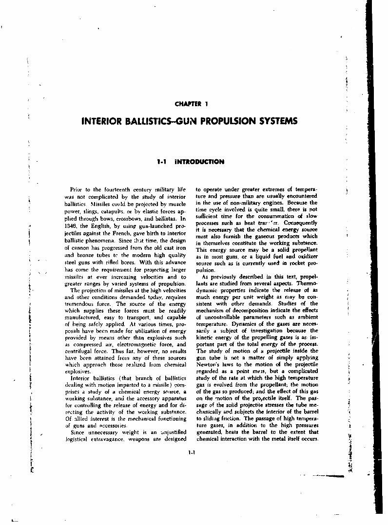
CHAPTER I
INTERIOR BALLISTICS-GUN PROPULSION SYSTEMS
1.1 INTRODUCTION
Prior to the fourteenth century military life to operate under greater extremes of tempera-was not complicated by the study of interior ture and pressure than are usually encounteredballistics. Missiles could be projected by muscle in the use of non-military engines. Because thepower, slings, catapults, or by elastic forces ap- time cycle involved is quite small, there is notplied through bows, crossbows, and ballistas. In sufficient time for the consummation of slow
1346, the English, by using gun-launched pro- processes such as heat trar 'er. Consequentlyjectiles against the French, gave birth to interior it is necessary that the chemical energy sourcej e amust also furnish the gaseous products whichballistic phenomena. Since 'hat time, the design in themselves constitute the working substance.of cannon has progressed from the old cast iron This energy source may be a solid propellantand bronze tubes te the modern high quality as in most guns, or a liquid fuel and oxidizersteel guns with rifled bores. With this advance source such as is currently used in rocket pro-has come the requirement for projecting larger pulsion.missiles at ever increasing velocities and to As previously described iu this text, propel.greater ranges by varied systems of propulsion. lants are studied from several aspects. Thermo-
The projection of missiles at the high velocities dynamic properties indicate the release of asand other conditions demanded today, requires much energy per unit weight as may be con-tremendous force. The source of the energy sistent with other demands. Studies of thewhich supplies these forces must be readily mechanism of decomposition indicate the effectsmanufactured, easy to transport, and capable of uncontrollable parameters such as ambientof being safely applied. At various times, pro- temperature. Dynamics of the gases are neces-posals have been made for utilization of energy sarily a subject of investigation because theprovided by means other than explosives such kinetic energy of the propelling gases is ar im-as compressed air, electromagnetic force, and portant part of the total energy of the process.centrifugal force. Thus far, however, no results The study of motion of a projectile inside thehave been attained from any of these sources gun tube is not a matter of simply applyingwhich approach those realized from chemical Newton's laws to the motion of the projectileexplosives, regarded as a point mo;s, but a complicated
Interior ballistics (that branch of ballistics study of the rate at which the high temperatureI' dealing with motion imparted to a missile) corn- gas is evolved from the propellant; the motion
prises a study of a chemical energy soiarce, a of the gas so produced; and the effect of this gasworking substance, and the accessory apparatus on the -notion of the proectile itself. The pas-for controlling the release of energy and for di- sage of the solid projectile stresses the tube me-recting the activity of the working substance. chanically and subjects the interior of the barrelOf allied interest is the mechanical functioning to slidiag fricion. The passage of high tempera-of guns and occessoiies. ture gases, in addition to the high pressures
Since unnecessary weight is an -anjustified generated, heats the barrel to the extent thatlogistical extravagance, weapons are designed chemical interaction with the metal itself occurs. I
----------------------.
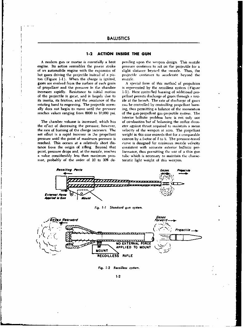
BALLISTICS
1-2 ACTION INSIDE THE GUN
A modem gun or mortar is essentially a heat pending upon the weapon design. This muzzleengine. Its action resembles the power stroke pressure continues to act on the projectile for aof an automobile engine with the expansion of slight distance beyond the muzzle. Thus, thehot gases driving the projectile instead of a pis- projectile continues to accelerate beyond theton (Figure 1-1). When the charge is ignited, muzzle.gases are evolved from the surface of each grain A special form of this method of propulsionof propellant and the pressure in tle chamber is represented by the recoilless system (Figureincreases rapidly. Resistance to initial motion 1-2). Here controlled burning of additional pro-of the projectile is grcat, and is largely due to pellant permits discharge of gases through a noz.its inertia, its friction, and the resistance of the zle at the breech. The rate of discharge of gasesrotating band to engraving. The projectile norm- cai, be contrclled by controlling propellant burn-ally does not begin to move until the pressure ing, thus permitting a balance of the momentumreaches values ranging from 6000 to 10,000 psi. of the gun-propellant gas-projectile system. The
interior ballistic problem here is not only oneThe chamber volume is increased, which has of combustion but of balancing the orifice diam-
the efect of decreasing the pressure; however, eter against thrust required to maintain a meanthe rate of burning of the charge increases. The velocity of the weapon at zero. The propellantnet effect is a rapid increase in ;he propellant weight in this case exceeds that for a comparablepressure until the point of maximum pressure is cannon by a factor of 2 to 5. The pressure-travelreached. This occurs at a relatively short dis- curve is designed for minimum muz~le velocitytance from the origin of rifling. Beyond that consistent with accurate exterior ballistic per-point, pressure drops and, at the muzzle, reaches formance, thus permitting the use of a thin guna value considerably less than maximum pres- tube which is necessarý to maintain the charac-sure, probably of the order of 10 to 30% de- teristic light weight of this weapon.
Recoilien/g Prts Gos. ,4 #O
Fig. 1.1 Standard gun system.
6 Rorwaor Forword-"," .
~ NO EXTERNAL FORCE
M U
RECOILLESS RIFLE
Fig. 1-2 Recoilless system.
1.2
Ii.
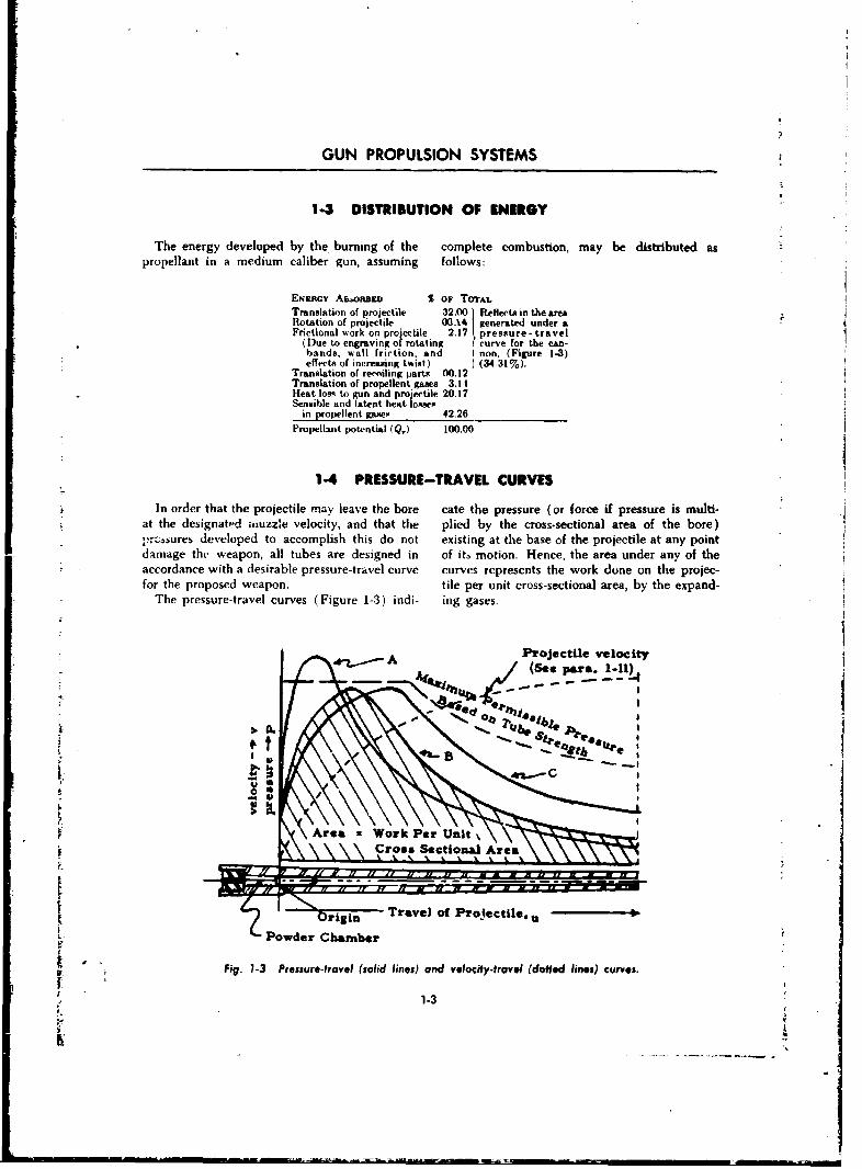
GUN PROPULSION SYSTEMS
1-3 DISTRIBUTION OF ENERGY
The energy developed by the burning of the complete combustion, may be distributed aspropellant in a medium caliber gun, assuming follows:
ENEaaOY A&,oRnan S OF TOTrAL
Translation of projectile 32.0 eflecsi the areaRotation of projectile 00.14 Ienrtdunder aFrictional work on procectile. 2.17 presoture -travel
(Due to engraving of rotating curve for the can-bands, wall friction. and I non, (Figure 1-3)effects of increasing twist) J (34-31%).
Translation of recoiling parts 00.12Translation of propellent gases 3.11IHeat los-s to gun and projectile 20.17Sensible and latent heat losses
in propellent gase!s 42.26Propellant potential (Q,) 100.00
1-4 PRESSURE-TRAVEL CURVES
In order that the projectile mray leave the bare cate the pressure (or force if pressure is multi-at the designated inuzzle velocity, and that the plied by the cross-sectional area of the bore)
prc,bures developed to accomplish this do not existing at the base of the projectile at any pointdamage the weapon, all tubes are designed in of it. motion. Hence, the area under any of theaccordance with a desirable pressure-travel curve curves represents the work dune on the projec-for the proposed weapon. tile per unit cross-sectional area, by the expand-
The pressure-travel curves (Figure 1-3) indi- ing gases.
A Projectile velocity(See par&. 1-1l)
I!.
PowderChambe
CC
Fig 1- P~sAretavz (Woli k Pier) and oit%~u~ dfe lns uvs
Crs1Scio"Ara
1-3I
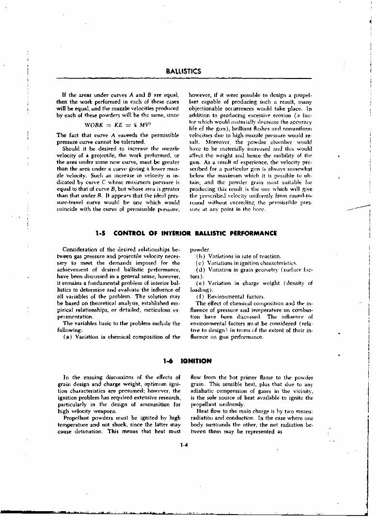
BALLISTICS
If the areas under curves A and B are equal, however, if it were possible to design a propel-then the work performed in each of these cases lant capable of producing such a result, manywill be equal, and the muzzle velocities produced objectionable occurrences would take place. Inby each of these powders will he the same, since addition to producing excessive erosion (a fac-
WORK-= KE MV2 tor which would materially decrease the accuracylife cf the gun), brilliant flashes and nonuniform
The fact that curve A exceeds the permissible velocities due to high muzzle pressure would re-pressure curve cannot be tolerated, suit. Moreover, the powder chaamber would
Should it be desired to increase the muzzle have to be materially increased and this wouldvelocity of a projectile, the work performed, or affect the weight and hence the mobility of thethe area under some new curve, must be greater gun. As a result of experience, the velocity pre-than the area under a curve giving a lower muz- scribed for a particular gun is always somewhatzle velocity. Such an increase in velocity is in- below the maximum which it is possible to ob-dicated by curve C whose maximum pressure is tain; and the powder grain Most suitable forequal to that of curve B, but whose area is greater producing this result is the one which will givethan that under B. It appears that the ideal pres- the prescribed velocity uniformly from round-to-sure-travel curve would be one which would round without exceeding the permissible pres-coincide with the curve of permissible plessure; sure at any point in the hore.
1-5 CONTROL OF IN¥ERIOR BALLISTIC PERFORMANCE
Consideration of the desired relationships be- powder.tween gas pressure and pojectile velocity neces- (h) Variations in rate of reaction.sary to meet the demands imposed for the (c) Variations in ignition characteristics.achievement of desired ballistic performance, (d) Variation in grain geometry (surface fac-have been discussed in a general sense; however, tors).it remains a fundamental problem of interior bal- (e) Variation in charge weight (density oflistics to determine and evaluate the influence of loading).all variables of the problem. The solution may (f) Environmental factors.be based on theoretical analysis, established em- The effect of chemical composition and the in-pirical relationships, or detailed, meticulous ex- fluence of pressure and temperature on combus-pet imentation. tion have been discussed. The influence of
The variables basic to the problem include the environmental factors must be considered (rela-following: tive to design) in teims of the extent of their in-
(a) Variation in chemical composition of the fluence on gun performance.
1-6 IGNITION
In the ensuing discussions of the effects of flow from the hot primer flame to the powdergrain design and charge weight, optimum igni- grain. This sensible heat, plus that due to an)ytion characteristics are presumed; however, the adiabatic compression of gases in \'ne vicinity,ignition problem has required extensive research, is the sole source of heat available to ignite theparticularly in the design of ammunition for propellant uniformly.high velocity weapons. Heat flow to the main charge is by two means:
Propellant powders must be ignited by high radiationi and conduction. In the case where onetemperature and not shock, since the latter may body surrounds the other, the net radiation be-cause detonation. This means that heat must tween them may be represented as
1-4
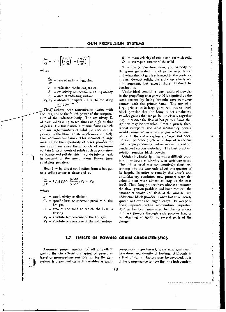
GUN PROPULSION SYSTEMS
dg. = cEA F/TV 'r l •G = mass velocity of gas in contact with solidd- f rfY - (L) D = average diamet2r of the solid
Thus the temperature, mass, and velocity ofwhere the gases generated are of prime importance;
and when the hot gas is enhanced by the presencedq, rate of radiant heat flow of incandescent solids, the radiation effects notdo only augment. but exceed those obta~ned byc = raciation coefficient, 0.172 conduction.E = emissivity or specific radiating ability Under ideal conditions, each grain of powder.4 = area of radiating surface in the propelling charge would be ignited at the
Ti, T2 = absolute temperature of the radiating same instant by being brought into completes sur•nces,-- contact with the primer flame. The use of a
"s, radiant heat transmission varies with large primer, as in large guns, requires so muchSthe area, and to the fourth power of the tempera- bl.ick powder that the firing is not smokeless.
-- - ture of the radiating body. The emissivity e Powder grains that are packed so closely together
of most solids is tip to ten times as high as that may so restrict the flow of hot primer flame thatof gases. For this reason, luminous flames which ignition may be irregular. From a pt:rely theo-
Z ~retical viewpoint, the most satisfactory primercontain large numbers of solid particles in sus- woul consist thexmost saticto uldpension ii the flame radiate much more intensely would consist of an explosive gas which wouldt n m u ao ipermeate the entire explosive charge and liber-Sthan nonluminous flames. This accounts in large
measure for the superiority of black powder for ate solid particles (such as mixture of acetylene
use in primers since the products of explosion and oxygen producing carbon monoxide and in-
contain large amounts of solids such as potassium candescent carbon particles). The best practicalSconainlare aount ofsolds uch s ptasium solution remains black powder.carbonate and sulfate which radiate intense heat. O lution rmnbcp der.
to the nonluminous flames from Originally', faulty ignition was a difficult prob-in contrast powder lem in weapons employing long cartridge cases.s e wThe primer used was comparatively short. ex-
Heat flow by direct conduction from a hot gas tending into the case only about one-quarter of
to a solid surface is described by: its length. In order to remedy this unsafe andunsatisfactory condition, new primers were de-
= d kC,•,T,0- (T, - T. Veloped that were almost as long as the casedT (D)a. itseif. These long primers have almost eliminated
where the slow ignition problem and have reduced theamount of smoke and flash at the muzzle. No
k = conmductiviy coefficient additional black powder is used but it is merelyC, = specific heat at conctant pressure of the spread out over the longer length. In weapons
hot gas firing separate-loading ammunition, imperfectL A = area of the solid to which the .-at is ignition has been minimized by placing a core
flowing of black powder through each powder bag orT, = absolute temperature of the hot gas by attaching an igniter to several parts of theT, = absolute temperature of the cold surface charge.
1-7 EFFECTS OF POWDER GRAIN CHARACTERISTICS
Assuming proper ignition of all propellant composition (quickness), grain size, grain con-grains, the characteristic shaping of pressure- figuration. and density of loading. Although in
S. •. travel or pressure-time reiationships for the gun a final design ail factors may be involved, it issystem, is dependent on such variables as grain of basic importance to note first, the independent
1.5
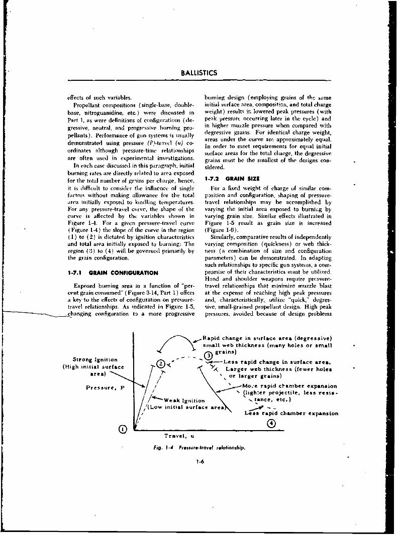
BALLISTICS
effects of such variables, burning design (employing grains of the samePropellant compositions (single-base, double- initial surface area, composition, and total charge
base, nitroguanidine, etc.) were discussed in weight) results it, lowered peak pressures (withPart 1, as were definitions of configurations (de- peak pressurc occurring later in the cycle) and
gressive, neutral, and progressive burning pro- in higher muzzle pressure when compared with
pellants). Performance of gun systems is usually degressive grains. For identical charge weight,areas under the curve are approximately equal.demonstrated using pressure (P)-trav-I (u) co- In order to meet requirements for equal initial
ordinates although pressure-time relationships surface areas for the total charge, the degressiveare often used in experimental investigations, grains must be the smallest of the designs con-
In each case discussed in this paragraph, initial sidered.burning rates are directly related to area exposedfor the total number of grains per charge; hence, 1-7.2 GRAIN SIZEit is diflicult to consider the influence of single For a fixed weight of charge of similar corn-factors without making allowance for the total pasition and configuration, shaping of pressure-area initially exposed to kindling temperatures. travel relationships may be accomplished byFor any pressure-travel curve, the shape of the varying the initial area exposed to burnir-.g bycurve is affected by the variables shown in varying grain size. Similar effects illustrated in
Figure 1-4. For a given pressure-travel curve Figure 1-5 result as grain size is increased(Figure 1-4) the slope of the curve in the region (Figure 1-6).(1 ) to (2) is dictated by ignition characteristics Similarly, comparative results of independentlyand total area initially exposed to burning: The varying composition (quickness) or web thick-region (2 ) to (4) will be governed primarily by ness (a combination of size and configurationthe grain configuration. parameters) can be demonstrated. In adapting
such relationships to specific gun systems, a com-1-7.1 GRAIN CONFIGURATION promise of their characteristics must be utilized.
Hand and shoulder weapons require pressure-Exposed burning area as a function of "per- travel relationships that minimize muzzle blast
cent grain consumed" (Figure 3.14, Part 1) offers at the expense of reaching high peak pressuresa key to the effects of configuration on pressure- and, characteristically, utilize "quick," degres-travel relationships. As indicated in Figure 1-5, sive, small-grained propellant design. High peakchanging configuration to a more progressive pressures, avoided because of design problems
S-- .Rapid change in sirface area (degressive)small web thickness (many holes or small
n grains)Strong Ignition '$ - - -,•---Less rapid change in surface area.
(High initial surface 7'" '>1k Larger web thickness (fewer holesarea) f a / ' or larger grains)
Pressure, P .Mo.e rapid c.-amber expansionS/ - '- (lighter projectile, less resis-
I Ignition .. tance, etc.)/,(Low initial surface area - - -
Less rapid chamrber expansion
Travel, u
Fig. 1-4 Pressure-travel relaoionship.
1-6
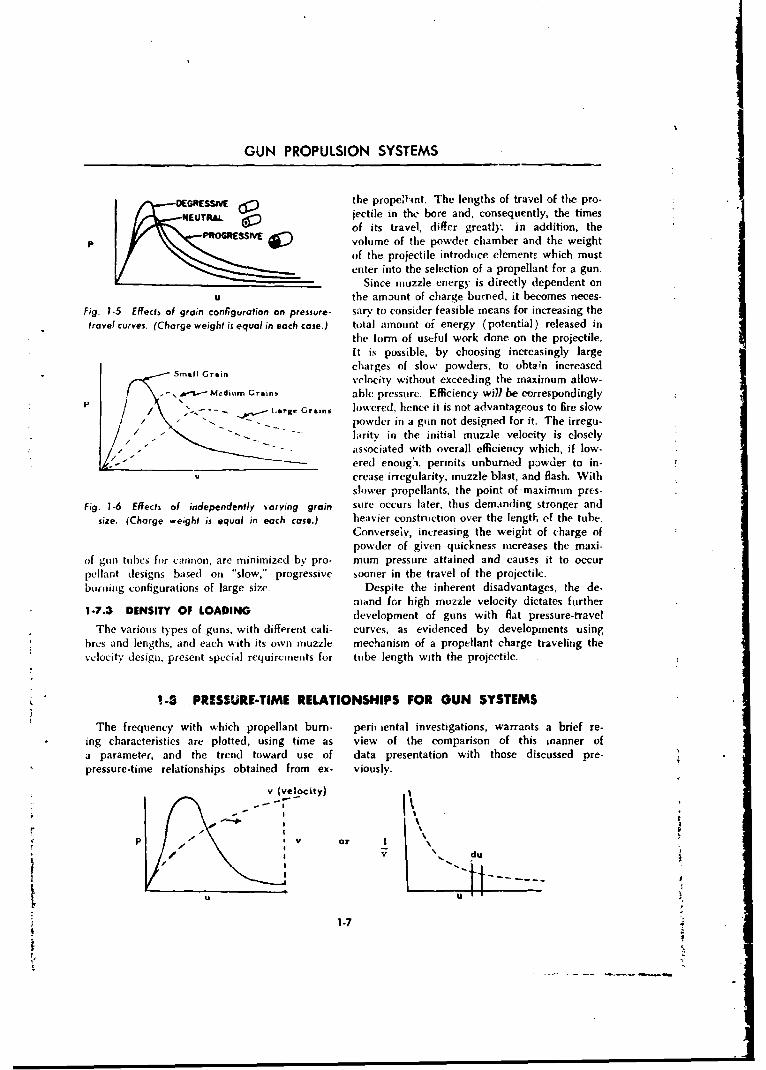
GUN PROPULSION SYSTEMS
DEGRESSMthe prope',Nnt. The lengths of travel of the pro-jectile in the bore and, consequently, the timesof its travel, differ greatly. in addition, the
PS VE volume of the powder chamber and the weightof the projectile introduce elements which mustenter into the selection of a propellant for a gun.
Since muzzle energy is directly dependent onu the amaunt of charge burred, it becomes neces-
Fig. 1-S Effeds of groin configuration an pressure- sary to consider feasible means for increasing thetravel curves. (Charge weight is equal in each case.) total amount oi energy (potential) released in
the form of useful work done on the projectile.It is possible, by choosing increasingly largecharges of slow powders, to ohta;n increasedf• Sall rai.velocity without exceeding the maximum allow-
-&.- Mkdinm Grains able pressure. Efficiency wil be correspondinglyI '.-- Le.g. Gr..... lowered; hence it is not advantageous to fire slow/ "• -powder in a guin not designed for it. The irregu-
larity in the initial muzzle velocity is closely"associated with overall efficiency which, if low-ered enoughi. permits unburned powder to in-
U crease irregularity, muzzle blast, and flash. Withslower propellants, the point ofmaximum pres-
Fig. 1-6 Effects of independently varying grain sure occurs later, thus demanding stronger andsize. (Charge weight is equal in each case.) heavier construction over the length of the tube.
Conversely, increasing the weight of charge ofpowder of given quickness increases the maxi-
of gun tubes for cannon, are minimized by pro- mum pressure attained and causes it to occurpellant designs based on "slow," progressive sooner in the travel of the projectile.burunig configurations of large size. Despite the inherent disadvantages, the de-
mdnd for high muzzle velocity dictates further1-7.3 DENSITY OF LOADING development of guns with flat pressure-travel
The various types of guns, with different cali- curves, as evidenced by developments usingbres and lengths, and each with its own muzzle mechanism of a propellant charge traveling thevelocity design, present special requirements for tube length with the projectile.
1-3 PRESSURE-TIME RELATIONSHIPS FOR GUN SYSTEMS
The frequency with which propellant burn- periT iental investigations, warrants a brief re-ing characteristics are plotted, using time as view of the comparison of this manner ofa parameter, and the trend toward use of data presentation with those discussed pre.pressure-time relationships obtained from ex- viously.
v (velocity)
- O
. - -or
U U
1-7
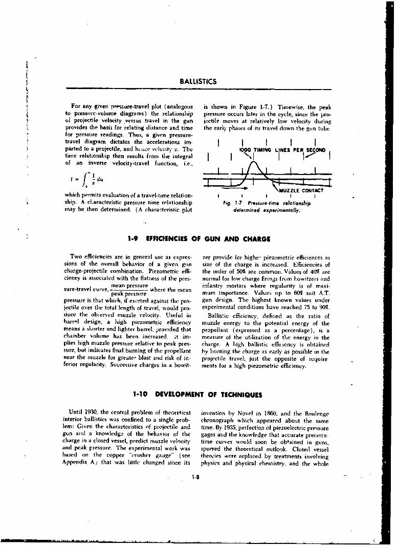
A
BALLISTICS
For any given pressure-travel plot (analogous is shown in Figure 1-7.) Timewise, the peakto pressurc-volume diagrams) the relationship pressure occurs later in the cycle, since the pro.of projectile velocity versus travel in the gun joctile moves at relatively low velocity duringprovides the basis for relating distance and time the early phases of its travel down the gun tubefor pressure readings. Thus, a given pressure-travel diagram dictates the accelerations im- I I I Iparted to a projectile, and hcice velocity v. The O=O TIMING LINES PER, SECONtime relationship then results from the integralof an inverse velocity.travel function, i.e.,
------- \ MUZZLE4CONTlAltwhich permits evaluation of a travel-time relation- I I I I Iship. A cLaracteristic pressure time relationship Fig. 1.7 Pressure-tfei relationshipmay be then determined. (A characteristic plot determined experimentally.
1-9 EFFICIENCIES OF GUN AND CHARGE
Two efficiencies are in general use as expres- zer provide for highe- piezometric efliciences assions of the overall behavior of a given gun size of the charge is increased. Efficiencies ofcharge-projectile combination. Piezometric effi- the order of 50% are common.. Values of 40% areciency is associated with the flatness of the pres- normal for low charge firings from howitzers and
mean pressure infantry mortars where regularity is of maxi-peak pressure mum importance. Values up to 60% suit A.T.
pressure is that which, if exerted against the pro- gun design. The highest known values underjectile over the total length of travel, would pro- experimental conditions have reached 75 to 90%.duce the ob.ýerved muzzle velocity. Useful in Ballistic efficiency, defined as the ratio ofbarrel design, a high piezometric efficiency muzzle energy to the potential energy of themeans a sLorter and lighter barrel, provided that propellant (expressed as a percentage), is achamber volume has been increased, it im- measure of the utilization of the energy in theplies high muzzle pressure relative to peak pies- charge. A high ballistic efficiency is obtainedsure, but indicates final burning of the propellant by burning the charge as early as possible in thenear the muzzle for greate, blast and risk of ir.- projectile travel; just the opposite of require-ferior regularity. Successive charges in a howit- ments for a high piezometric efficiency.
1-10 DEVELOPMENT OF TECHNIQUES
Until 19•'0, the central problem of theoretical invention by Novel in 1860, and the Boulengeinterior ballistics was confined to a single prob- chronograph which appeared about the samelem: Given the characteristics of projectile and time. By 1935, perfectfon of piezoelectric pressuregun and a knowledgz of the behavior of the gages and the knowledge that accurate pressurie-charge in a closed vessel, predict muzzle velocity time curves would soon be obtained in guns,and peak pressure. The experimental work was spurred the theoretical outlook. Closed vesselbased on the copper "crusher gauge" (see theo'ies were replaced by treatments involvingAppendix A, that was little changed since its physics and physical chemistry, and the whole
rn-S
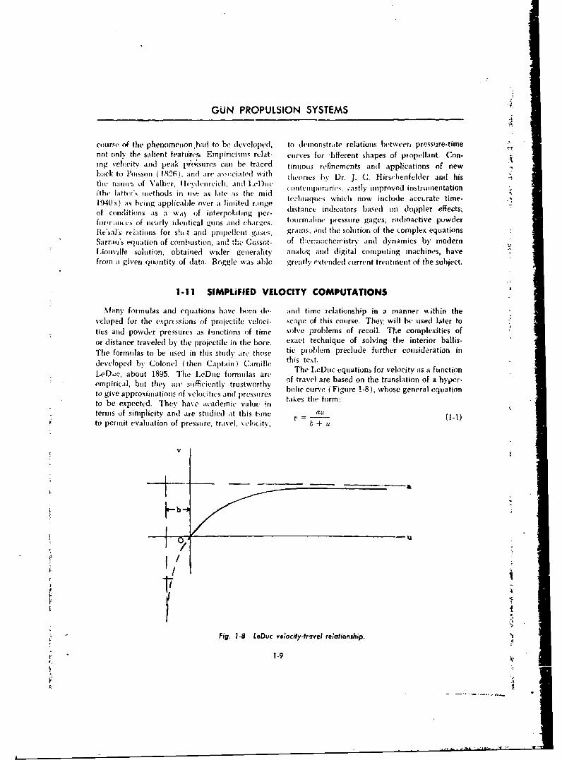
GUN PROPULSION SYSTEMS
couirse ot the phenomenon bad to he developed, to demonorstrate relations between pressure-timenot onI4 the salient featuveos, Einpiricisms relat- curves for 'lifforent shapes of piropellant. Con-ing vehocitv and peak prc~sires can be traced tinunus refinements and applications of newhack to Poiwsson (I M2 ) idi are aNooiaited with ireslIr.JC.- ichnldrfdhs-the namles of \'allier, Tlevdeiireich, and 1.eItii c hois1 r .C - rt-efedradhs.
coriteliiporaries; .-astly improved instrumentation(the liftters iiietliuds in iuse as late as the midl thiic ncinwicueacrt ie1940's) its being applicable over at limited range ditvabince indich torw include acdoppter tie-sof conditions as a wa\ of interpolating per- dsacinctosbed iloperfet;formantes of nearly, idleIwical guns and charues. tourimaline pre~ssure gages; ra(Iioactie powderie'sal's relations for shu~t and propellent giss grains; 'Ind the solution of the complex equationsSarraois equation of combustion, and thew Gossot- of thdi~eroheri-istrv n yaisb-mdrL~iouville solution, obtained Wider vgenerality analogý aind digital computing machines, havefrom a given quantity of data. Roggke was able greatly extendled current treatment of the subject.
1-11 SIMPLiFIED VELOCITY COMPUTATIONS4
Niany formulas and equations have been de- and] time relationship in a manner m~ithin thevcloped for the exprtszions of projcctile veloci- scope of this course. The), will be used later toties and powder pressures as fuinctions oif time solve problems of recoil. The complexities ofor distance trave~led by the projectile in the bore, exact technique of solving the interior ballis-The formulas to be used in this study atrc those tie problem preclude further consideration indeveloped by Colonel (then Captain ) Camille this text.
The Leu qainsfrvlct isafntoLeDuc, about 1895. The 1.eDtc formulas areeueqatosfrvlcyasauninempirical, but they ai sexifi~ciently trustworthy. of travel are based on the translation of a hyper-to give approximations Of Velocitiesand pressnres bolic curve ( Figure 1-8), whose general equationto be expected. They have academic valuE in takes the form:terms of simplicity and are studied at this time E. -al C-to permit evaluation of pressure, travel, vekocity, +u
v
V II
4' - Fig. 1-8 [.Doc veiocify-tr'oveI reiafionship.
1-9
FJ
BALLISTICS
where the size of grain, -and percentage of remaining
v is velocity of the projectile at any point, in te volatiles, and is largest for slow powders. Itmaybe seen that b will be dircctly proportional to this
bore, ft/sec constant, since, for example, a slov powderu is travel of the projectile in the bore, ft (large constant) will cause the point of maximuma Ii empirical constant, ft/sec pressure to occur farther down the bore than willb. is empirical constant, ft a fast powder, and the magnitude of b varies
For munzzle conditions (1-1) may be written with the distance to this point of maximum
aU ftSUV _ •a 1-2) all.
b + U - rom (1-1), v ----. ,the velocity for any
where pniv,, in thw bore may be obtained.
V = muzzle velocity, ft/see The kinetic energy ofthe projectile at. any taime-= lengt~h of bore, ft is , , where w is the weight of the projectile
The values of the constants a and b must be - .determined empirically and checked and cor- i trected by ,.cual test firings in order that the Ilie empirical constants, a and 1, are c'o.m-best approximation to the actual velocity can putod from the results of oxperimcrtal firingsbe determined. The positive branch of the curve adiusted to the propellant tsed. For example:approaches a as a limit. Thus, if the gun tub, 11.
were of infinite length and the powder gases a = 6823 ()0allowed to expand without limit, the expression u,
U would approach unity, and v would equal whereb+ua. This may be seen graphically in Figure 1-8. A = density of loading
There is a definite relationship between the w = weight of charge, lbvalue of b and the travel of the projectile to the i = weight of projectile, lbpoint of maximum pressure. It can be shownby calculus that when the pressure, and hence (The constant 6823 represents the potential of
acceleration, is a maximum, the relationship nitrocellulose propellant.)
u = b exists (see Par. 1-13).'= ( -- ) (e 2,3
In practice, with the LeDuc Method a and bare determined by choosing them so as to re-produce muzzle velocity (1-2) and maximum where
pressure in a number of typical cases, and thus powder constant., or a measure of thedetermine empirical relationships. :j"quickness" of the pwder (varies inversely
For each powder manufactured, ;-%vwder as the \c,.,,city of burning)constant which represents the relativc quickness 6 = specific gravity of the powder (usuallyof the powder is determined. This xvii. ý is d6 -- twr.n k 1.5 and 1.6)pendent upon such factors as the web otickness. S = vohume of the powder chamber, cu in.
1-12 EFFECTS OF VARIATIONS IN THE GUN PROJECTILE SYSTEM
The effects of variations of the propc1lant on ometry, and grain size, the variations in per-the velocity and pressure have bcvi discussed. formance are iud'cated in the followingFo: a charge of given composition, grain gc- paragraphs.
1-10
GUN PROPULSION SYSTEMS
1-12.1 GUN TUBE LENGTH changes in the volume of the powder chamber
By examining LeDuc's equation it may bc may be caused by using a different type of gun
seen that if an increase is made in the length of or projectile, or by nonuniform seating of thethe gun tube, the muzzle velocity should rise. projectile. In general, a dcc,'ease in the densityThere is an actual increase because the powder of loading decreases the velocity and the maxi-
gases are all being expanded within the tube, mum pressure but increases the length of travelrather than released to the air behind the pro- to the point of maximum pressure.jectile. Up to a certain point the gun tube may With the same gun and projectile, a change inbe lengthened to increase the muzzle velocity; density of loading is obtained only by changinghowever, there is a practical limit beyond which the weight of powder charge or by nonuniformthe additional velocity does not justify the added seating of the projectile. In either of these in-weight. stances, for small changes, the approximate rule
is: The velocity varies as the square root of the1-12.2 GUN CHAMBER density of loading.
If the volume of the powder chamber is variedfor a given charge, the density of loading will 1-12.5 SECTIONAL DENSITYvary. Such variations may occur when a different If the weight of a projectile of a given diame-projectile is used; the projectile is not uniformly ter is reduced, the projectile is said to have aseated; or when the charge is used in a different decreased sectional density, defined as:gun. In general, an increase in the density of weightloading will cause an increase in velocity and (diameter)2
maximum pressure, but will decrease the length where the weight is in pounds and the diameterof travel to the maximum pressure point. For is in inches. Representative values for variousexample, a 1% increase in density of loading in projectile types and calibers are:a 120-mm gun increases the velocity 0.3%, or Projectie Typefrom 3100 ft/see to 3110 ft/sec. and Caliber Sectional Density
1-12.3 PROJECTILE WEIGHT 155-mm HE 2.557A decrease in projectile weight has an effect 90-mm AP 1.892
on the pressure-travel curve similar to that of an 90-mm HVAI 1.76increase in grain size. The peak maximum pres- 76-mm HEP 1.104sure is lowered, its position is moved forward, .30 BALL M2 .237and the area under the curve is decreased. The .30 AP M2 .260muzzlc energy is lessened but the lowered shell Low sectional density is desirable from anweight has the effect of increasing muzzle veloc- interior ballistics viewpoint but undesirable fromity. The muzzle velocitv varies approximately an exterior ballistics viewpoint, since the pro-inversely as the square root of the weight of the jectile has less inertia and will be more ea.ilyprojectile; or more accurately, y = Kw -", n retarded by the air. As a means of providing lowvarying between 0.35 and 0.50. The lower value sectional density of the projectile while it is inrepresents the effect of a large dlecrease in projec- the gun, and increasing this factor while the
tile weight, This same effect can be shown by projectile is in flight, methods employed have as
examnining LePuc's equation for velocity and a goal the decrease in diameter of the projectileequations for a and b. (Consideration of the ex- after it leaves the gun tube. Projectile typespression for the energy imparted to the projectile utilizing this principle are:within the gun, 1/2 MV", will show that V varies (a) Discarding sabot projectile.inversely as (w)l'/' if the total energy imparted (b) Folding skirt projectile (used in a taperedis the same.) bore weapon).
Other methods of reducing the sectional den-1-12.4 DENSITY OF LOADING sity are the composite rigid projectile (HVAP)
A change in density of loading may result and the Russian Arrowhead. In these cases, thefrom clanges in the w'viilht (of charge or changes sectional density remains low during the flight ofi the, volimnei of the )owvd],r chani hr; and the the projectile.
1-11
BALLISTICS
1-13 PRESSURE COMPUTATIONS
An expression for pressure in the gun tube d /dv\may be derived from LeDuc's velocity equation. d0The rate of change of momentum: Y
F - Ma or
12PA = (IL) (dvN d a2 bi)i~~ ~ 'PA f t) (--t \( b +" u) 1)
= (7w d (b+u)3 b) (du)- (albu) (3) (b+u) (du)
Sd) (b + u)6
P = pressure producing acceleration, psi orA = cross-sectional area of the gun tube, sq in.
Differentiating LeDuc's equation for velocity, b + u 3u = 0, whence b
2
au (b + u) a d - Substituting in (1-3) above,
Wt b +ui (b + u)' 4 u'a 2 (14)ab d27Agb
( ( L As noted previously, actual tube pressureBut, (b+ u d must overcome friction; force the rotating band
through the rifling; impart rotation to the pro-du au jectile; and produce acceleration. The actualdf bv +u bore pressure, which has been found experi-
mentally to be approximately 1.04 times theSubstituting in the expression above, pressure producing translation of the projectile
dv = ( bu \ ( au "~= a2bu [see (1-3)], is given by the formuladt (b"+b (b + u) (b + u)3 P(actual) 1.04wa 2bu
Thus gA(b + u)•3
wa2bu Also from (1-4), the actual maximum pressure isP = Ag.(b + u) 3 (1-3) given by the formula
Since maximum pressure must correspond to the P,,,(actual) = 4. 6w 2 (1-6)point of maximum acceleration, 27 Agb
1-14 EFFECTS OF VARYING CONDITIONS IN SERVICE
During the service life of a gun tube, a number conditions for the exterior trajectory of the pro-of variables may affect its ballistic performance jectile. Examples of two methods by which suchin a manner which a designer may not predict, conditions are resolved to standard conditionsbut which must be anticipated. Wear character- are indicated here. Firing tables include meansistics of the bore vary widely between the ex-tremes of large, low velocity howitzers, and ton absoring the and ardicoadi-hypcrvelocity tank and anti-tank guns. Environ- tions into firing data, and tube serviceabilitymental conditions such as ambient temperature, standards are used to predict service life andgun temperature, deterioration of ammunition effects of wear on specific guns firing specificin storage, and others, thus may affect the initial types of ammunition.
1-12

GUN PROPULSION SYSTEMS
"i 1-14.1 TEMPERATURE OF THE POWDER residues generated from the burning of the
Firing tables are based on a powder tempera- propellant, as well as by the- movement of the
ture of 70'F, at the time of firinv An increase projectile through the bore. Erosion is often
in this temperature increasr., the potential and divided into three phases:
the burning rate of the propellant, giving a (a) Gas erosion. The first indications of thisgreater muzzle velocity. Conversely, a decrease type of erosion are hairline cracks or a checker-in the powder temperature reduces the velocity. ing effect near the origin of rifling. This is prob-A tabulation of the effects of variation from ably caused by continued expansion and contrac-standard powder temperature is incorporated in tion of the metal of the gun tube in conjunctionthe,tables to enable the necessary corrections to with the brittleness of the metal caused by thebe made in the firing data. An extract from firing absorption by the gun tube of carbon and nitro-tables for the 105-mm howitzer is shown in gen from the powder, producing a brittle carbideTable 1-1. or nitride. This checkering or cracking is not
erosion in itself but makes it easier for the hot1-14.2 TEMPERATURE OF THE GUN gases moving at high velocity to wash away the
A change in muzzle velocity will occur because metal. Figure 1-9 shows the checkering and gasof high gun temperature due to rapid fire. As erosion near the origin of rifling and the gradualan example, 30 rounds fired rapidly in a 90-mm wearing away of the rifling.gun will cause a breech metal temperature of (b) Scoring. Scoring is attributed to a nozzleabout 275'F. If a round is left in the gun before or vent action of the gas escping past the rotat-firing, the powder will be affected by this tcm- ing band. Sometimes tool marks or rifling defectsperature; however, if the round is fired quickly, start the scoring because of lesser obturation orthere will be no appreciable change in powder scaling by the rotating band at the defect. Oncetemperature and consequently, no velocity started, scoring, unlike gas erosion, increases"change. The spontaneous firing of an overheated rapidly with each round although it does notround left in a hot breech recess is commonly usually become evident until after several roundstermed "cook-off." have been fired. Scoring usually begins on the1-14.3 EROSION IN THE GUN BORE upper part of the bore around the 12 o'clock
region, due to the weight of the projectile caus-Erosion is the process of removal of metal ing the greater clearance at the top when seated.
from the surface of a gun tube by the movement This is usually more evident in guns firingat high velocities of high-temperature gases and separate-loaded ammunition. When firing is done
TABLE 1-1 EXTRACT FROM FIRING TABLES FOR 105-MM HOWITZER.SHELL H.E. MI MV = 710 FT/SEC, CHARGE 2
Change in Velocity Due To Change in Temperature of PowderTemperal ure of Change in Temperature of Change in
Powder, °1" Velocity, ft/sec Powder, °F Velocity, ft/sec
0 -22 50 -6
10 -19 60 -320 -16 70 030 -13 80 +340 -9 90 +6
50 -6 100 +9
1-13
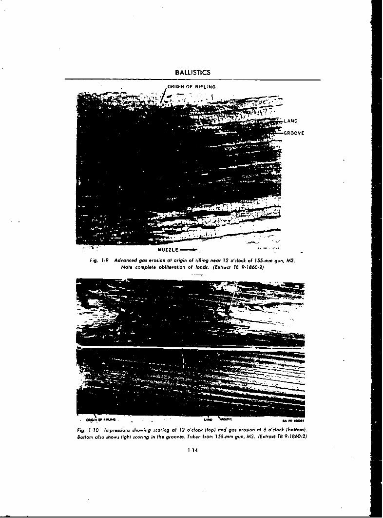
BALLISTICS
ORIGIN OF RIFLING
- ~MUZZLE-.fig. 1.9 Advanced gas erosion ot origin of rifling near 12 o'clock of 155-mmn gun, M2.
Not* complete obliteration of lands. (Extract TS 9-1860-2)
* ýWotw K WLM4 - -LAP0 59
Fig. 1-10 Impressions shuwing scoring ot 12 o'clock (top) and gas erosion of 6 o'clock (bottom).Bottom also shows light scoring in the grooves. Tiilcen frorn 155-mm gun, M2. (Extract T8 9-1860-2)
1-14
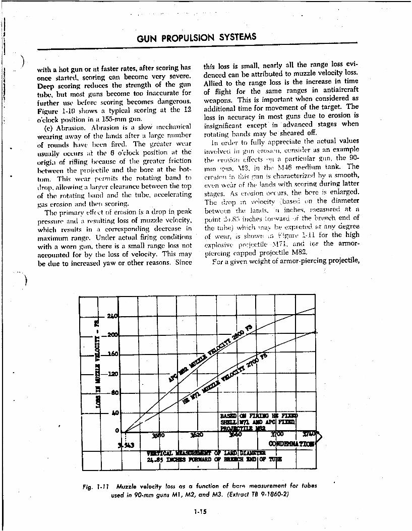
GUN PROPULSION SYSTEMS
with a hot gun or at faster rates, after scoring has this loss is small, nearly all the range loss evi-
once started, scoring can become vcry severe. denced can be attributed to muzzle velocity loss.
Deep scoring reduces the strength of the gun Allied to the range loss is the increase in timeItube, but most guns become too inaccurate for of flight for the same ranges in antiaircraft
further use before scoring becomes dangerous. weapons. This is important when considered as
Figure 1-10) shows a typical scoring at thc 12 additional time for movement of the target. The
O'clock position in at 155--mm gun. loss in -accuracy in most guns due to erosion is
(c) Abrasion. Abrasion is at slow mecehanical insignificant except* in advanced stages when
wearing away of thc lands after a large numbcr rotating bands may be sheared off.
of roundls hakve been fired. Thc greater wear In order to fully appreciate the actual values
usually occurs af the 6 o'clock position at the involve'i in gnin c-ro~siu', censi41&r as an example
Origi.I of rifling, because of thc greater friction the crosion cffects' ,!i a particiflar gun, the 90-
betw~een the projectile and the bore at the hot- mm in. %1". in the N146 mediuim tank. The
torn. This wvear pcrm its the rotating band to Vre1SienT m ismn is c~haracterized by a smooth,
drop, alwn!a lrt~er clearance b~etween the top evvn weitr of the lands with secring during latter
of the rotating band and. the tube, accelerating stages. A~s e:rosion orcurs, the bore ;s enlarged.
gas erosion adthenk scoring. Thc drop :n veiocity Jxisel ~n the diameter
The primary eff(Ct oft erosion is a drop in peak betwee(.n -he landls. ti inches, ineasu~re0 at
pressitre and a resulting loss of muzzle velocity, point 2li.R8C inches :rjrwvard 4i the, breech end of
which results in a corresponding decrease in the tkubf,) lhc nav, he expecti-o at any degree
maximum range. Under actual firing conditions of we-ar, IS Showl .5o 1ntu -11 for the high
with a worn gun, there is a small range loss not explosive prJecetile N-71. -nd ior the armor-
accounted for by the loss of velocity. This may piercing eapped projectile M82.
be dlue to increased yaw or other reasons. Since For a given weight of armor-piercing projectile,
'2O0
Fig. 1-11 Muzzle velocity loss as a function of berp measurement for tubes
used in 90-mm guns Ml, M2, and M3. (Extract TB 9-1860-2)
1-15
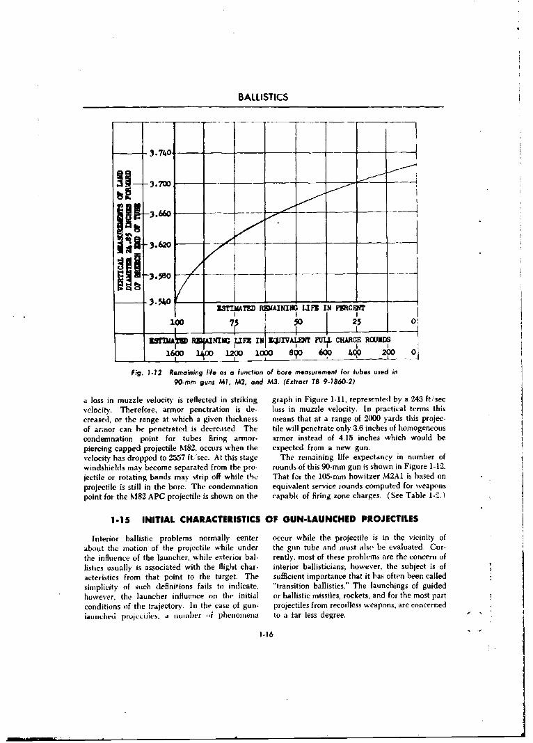
BALLISTICS
-3.740-
-3.700--
I 1-3.66o
3.54WrITEJAD RDIAINIIG LIFIC IN PIRCENT
n=MR5fIAXNr IFX IfNI IZWIVA if FULL CHARGE ROAUNDSI II1 - - I
_1 _ R i fe 12 f 1i_ - _ e fo u useD -n
Fig. 1.12 Remsamning Mde as a function of bore measurement for tubes used in90-mn guns M1, M2, and M3. (Extract TB 9-1860-2)
a loss in muzzle velocity is reflected in striking graph in Figure 1-11, represented by a 243 ft/secvelocity. Therefore, armor penetration is de- loss in muzzle velocity. In practical terms thiscreased, or the range at which a given thickness means that at a range of 2000 yards this projec-
of armor can be penetrated is decreased. The tile will penetrate only 3.6 inches of homogeneouscondemnation point for tubes firing armor- armor instead of 4.15 inches which would bepiercing capped projectile M82. occurs when the expected from a new gun.velocity has dropped to 2557 ft.'sec. At this stage The remaining life expectancy in number of
windshields may become separated from the pro- rounds of this 90-mm gun is shown in Figure 1-12.jectile or rotating bands may strip off while the That for the 105-rmm howitzer M2AI is based on
projectile is still in the bore. The condemnation equivalent service rounds computed for weaponspoint for the M82 APC projectile is shown on the capabk of firing zone charges. (See Table 1-'-.)
1-15 INITIAL CHARACTERISTICS OF GUN-LAUNCHED PROJECTILES
Interior ballistic problems normally center occur while the projectile is in the vicinity ofabout the motion of the projectile while under the gun tube and must also be evaluated, Cur-the influence of the launcher, while exterior bal- rently, most of these problems are the concern oflistics usually is associated with the flight char- interior ballisticians; however, the subject is ofacteristics from that point to the target. The sufficient importance that it bas often been calledsimplicity of such definitions fails to indicate. "transition ballistics." The launchings of guidedhowever, the launcher influence on the initial or ballistic missiles, rockets, and for the most partconditions of the trajectory. In the case of gun- projectiles from recoilless weapons, are concernediaumiched prujc'iiles, a number oi phenomena to a tar less degree. "
1.16
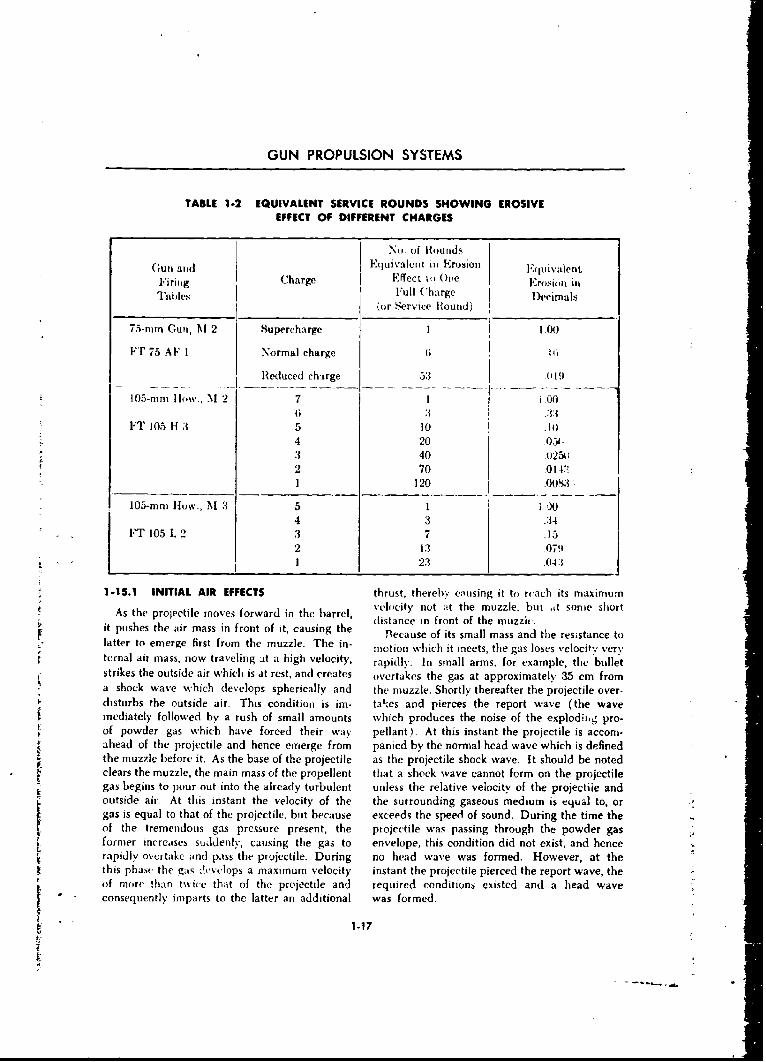
GUN PROPULSION SYSTEMS
TABLE 1.2 EQUIVALENT SERVICE ROUNDS SHOWING EROSIVEEFFECT OF DIFFERENT CHARGES
No. of Rounds
G(un and I'quivalelt in Erosion l"(luivalentFiring Charge Effect to O(c Erosion in
TablIes Full Charge Decimals(or Service Round)
75-nim Gun, M 2 Supercharge 1 100
i"T 75 AF I Normal charge 611
Reduced charge 53 0 19
105-mm Hlow., 'M 2 7 1 i 006 3 A.3
FT 105 H 3 5 10 .104 20 031."3 40 0"25N'2 70 014:1 120 .001S M
105-mm How., M 3 5 1 i )0O4 3 .A4
FT 105 L 2 3 7 -15
2 13 0791 23 .043:
1-15.1 INITIAL AIR EFFECTS thrust, thereby cmusing it to rcach its maximum
As the projectile moves forward in the barrel, velocity not at the muzzle, but tt some short(distance in front of the muzzh-.Sit pushes the air mass in front of it, causing the Blecause of its small mass and the resistance to
latter to emerge first from the muzzle. The in- motion which it meets, the gas loses vclocit., ver'.ternal air mass, now traveling it a high velocity, rapidly. In small arms, for example, the bullet
strikes the outside air which is at rest, and creates overtakes the gas at approximately 35 cm froma shock wave which develops spherically and the muzzle. Shortly thereafter the projectile over-disturbs the outside air. This condition is im- takes and pierces the report wave (the waveimediately followed by a rush of small amounts which produces the noise of the explodiimg pro-of powder gas which have forced their way pellant). At this instant the projectile is accom-ahead of the projectile and hence emerge from panied by the normal head wave which is definedthe muzzle before it. As the base of the projectile as the projectile shock wave. It should be notedclears the muzzle, the main mass of the propellent that a shock wave cannot form on the projectilegas begins to pour out into the already turbulent unless the relative velocity of the projectile andoutside air- At this instant the velocity of the the surrounding gaseous medium is equal to, orgas is equal to that of the projectile, but because exceeds the speed of sound. During the time the
former increases suddenly, causing the gas to envelope, this condition did not exist, and hence
rapidly overtake and pass the projectile. During no head wave was formed. However, at thethis phase the gas -levclops a maximum velocity instant the projectile pierced the report wave, theof more !han twice that of the projectile and required conditions existed and a head wave
" consequently imparts to the latter an additional was formed.
1.17
,,..
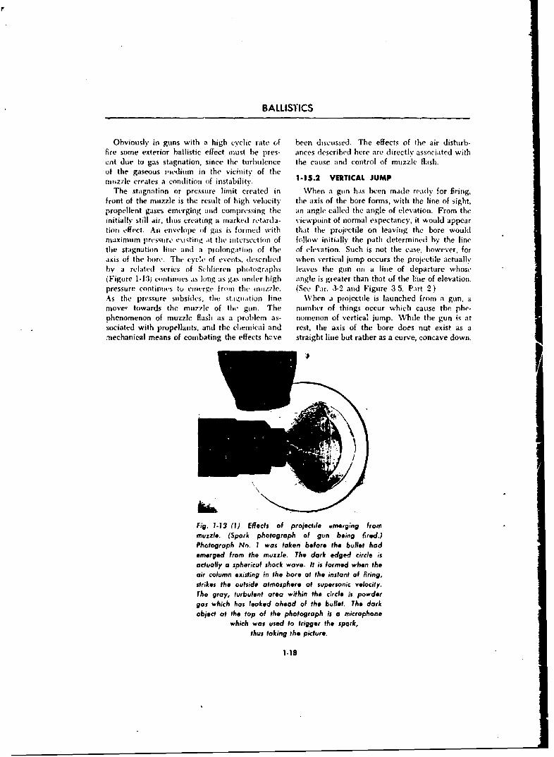
BALLISTICS
Obviously in guns with a high cyclic rate (if been discussed. The effects of the air disturb-fire some exterior ballistic effect must be pres- ances described here are directly associated withent due to gas stagnation, since the turbulence the cause and control of muzzle flash.of the gaseous medium in the vicinity of themuzzle creates a condition of instability. 1-15.2 VERTICAL JUMP
The stagnation or pressure limit created in When a gun has been made readly for Bring,front of the muzzle is the result of high velocity the axis of the bore forms, with the line of sight,propellent gases emerging and compressing the an angle called the angle of elevation. From theinitially still air, thus creating a marked retarda- viewpoint of normal expectancy, it would appeartiou effect. An envelope of gas is formied with that the projectile on leaving the bore wouldmaximum pressure existing at the mitersection of follow initially the path determined by the linethe stagnation line and a prolongation of the of elevation. Such is not the case, however, foraxis of the bore. The cyee of events, described when vertical jump occurs the projectile actuallyby a related series of S.hlieren photogr.tphs leaves the gun on a line of departure whose(Figure 1-13) continues as long as gas tnder high angle is greater than that of the lue of elevation.pressure continues to emierge from the muzzle. (See Par. 3-2 and Figure 3-5, Part 2.)As the pressure subsides, the staantation line When a projectile is launched from a gun, amove! towards the mu7zle of thie gun. The number of things occur which cause the phe-phenomenon of muzzle flash as a problem as- nomenon of vertical jump. WVhile the gun is atsociated with propellants, and the chemical and rest, the axis of the bore does nQt exist as amechanical means of combating the effects hcve straight line but rather as a curve, concave down.
Fig. 1-13 (1) Effects of projectile wmeoging frommuzzle. (Spark photograph of gun being fired.)Photograph No. I was taken before the bullet hodemerged from the muzzle. The dark edged circle isactually a spherical shock wave. It is formed when theair column existing in the bore at the instant of firing,strikes the outside atmosphere of supersonic velocity,The gray, turbulent area within the circle is powder
gas which has leaked ahead of the bullet. The darkobject at the top of the photograph is a microphone
which was used to trigger the spark,
thus taking the picture.
1-18
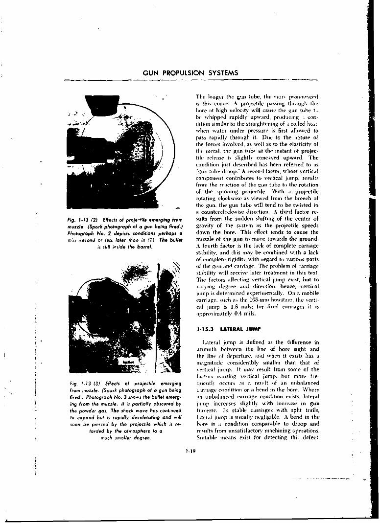
GUN PROPULSION SYSTEMS
"The longer the gu,, tube, the mor, pronournzcedis this curve. k projectile passing thl ,hisg the)ore at high velocity will cause the gun tube to
be whipped rapidly upward, producing . con--dition similar to the straightening of a coiled huscwhen water tinder pressure is first allowed topass rapidly through it. Due to the nature ofthe forces involved, as well as to the elasticity ofthe metal, the gun tub- at th, instant of projec-tile release is slightly concaved upward. Thecondition just described has been referred to asgun tube droop.- A seconl factor, whose vertic i!
component contributes to vertical jump, resultsfrom the reaction of the gun tube to the rotation
of the spinning projectile. With a projectilerotating clockwise as viewed from the breech of
-_ the gun. the gun tube will tend to be twisted in
a counter clockwise direction. A thi-d factor re-Fig. 1.13 (2) Effects of proje-tfie emerging from suits from the sudden shifting of the center of
muzzle. (Spark photograph of a gun being fired.) gravity of the system as the projectile speedsPhotograph No. 2 depicts conditions perhaps a down the bore. This effect tends to cause the
m~cr second or le.s later than in (1). The bullet muzzle of the gun to move towards the ground.
is still inside the barrel. A fourth factor is the lack of complete carriagestability, and this may be combined with a lackof complete rigidity with regard to various parts
. " "of the gun and carciage. The problem of -arriage"stability will receive later treatment in this text.The factors affecting vertical jump exist, but tovarying degree and direction. hence, vertical
junmp is determined experimentally. On a mobilecarriage. such as the '05-mn) howitzer, the verti-cal jump is 1.8 mils; for fixed carriages it isapproximately 0.4 mils.
1-15.3 LATERAL JUMP
Lateral jump is defined as the difference inazimuth between the line of bore sight andthe line of departure, and when it exists has amagnitude considerably smaller than that ofvert~cal jump. It may result from some of the
facirs causing vertical jump. but more fre-
Fig. 1-13 (3) Effects of projecile emerging quently occurs as a resvlt of an unbalancedfrom :'Iuzzle. (Spark photograph of a gun being carriage condition or a bend in the bore. Wherefired.) Photograph No. 3 shows the bullet emerg- an unbalanced carriage condition exists, lateraling from the muzzle. it is partially obscured by inimp increases slightly with increase in gunthe powder gas. The shock wave has continued traverse. In stable carriages with split trails,to expand but is rapidly decelerating and will !,tterai jump 's usually negligible. A bend in thesoon be pierced by the projectile which is re- bore is a condition comparable to droop and
forded by the atmosphere to a results from unsatisfactory machining operations.much smaller degree. Suitable ieans exist for detecting thi, defect,
1.19
BALLISTICS
which, if serious enough, becomes a cause for is held within specified limits, thus producinggun tube rejection. Normally, bend in the bore a negligible amount of lateral jump.
REFERENCES
1 Corner, Theortj of Interior Ballistics of Guns. 5 F. R. W. Hunt, Internal Ballistics, PhilosophicalJohn Wiley and Sons, N. Y., Chapters I Library, Inc., N. Y., 1951.and IV.
2 Deming, Chemistry, John Wiley and Sons, 6 Robinson, Thermodynamics of Firearms,N.Y. McGraw-Hill Book Co., Inc., N. Y., Chapters
XI and XII.3 F. P. Dunham, Thermodynamics, Prentice-
Hall, Inc., N. Y. 7 U.S. Army Technical Bulletin No. 9-1860-2,
4 Hayes, Elements of Ordnance, John Wiley and Evaluation of Erosion and Damage in Can-Sons, Inc., N. Y., Paragraph 68-71. non Bores.
1-20
CHAPTER 2
INTERIOR BALLISTICS-THRUST PROPULSION SYSTEMS
2-1 INTRODUCTION
Since World. War II, the design of modern rockets, guided missiles, and jet-powered super-weapons has placed increasing demands on con- sonic aircraft which rely on the thrust-producingventional systems in terms of range, velocity, reaction motor as the propulsion means.accuracy, and flexibility. These demands have Within the broad category of reaction motorsexceeded the capabilities of projectile-type sys- lies the solid or liquid fuel rocket motor and thetems as well as the capabilities of reciprocating jet. The solid and liquid fuel rocket motor carriesengine-type aircraft to deliver an effective its own oxidizer, permitting thrust to be de-destructive missile against an enemy. In past veloped within as well as outside the atmosphere.centuries, lack of dependability and accuracy The liquid fuel jet engine relies on atmosphericcaused rejection of simple rockets as being in- oxygen to support combustion and is representedeffective, inefficient, and unpredictable despite by turbo jet, pulse jet, and ram jet designs.their obvious potential. New propulsion tech- In this chapter the basic principles applicableniques and modem scientific and technological to thrust propulsion by reaction motors will beadvances have now, however, permitted the discussed. Following this, the problems uniquedevelopment of rocket motors and air breathing to rockets and jets are discussed separately,- asjet engines to the extent that modern weapons applicable to specific weapon propulsion re-systems are increasingly centered about free quirements.
2-2 REACTION MOTOR PRINCIPLES
Contrary to popular beliefs, a reaction motor fluid is not ejected from within the vehicle. --irdoes not push against the air to obtain its thrust. the propeller were put in a duct and the airThe thrust is obtained by increasing the mn- allowed to pass through the vehicle, one wc,12mentum of the working fluid and by a pressure then have mechanical jet propulsion.differential. A reaction motor consists essentially of a pro-
Newton's third law of motion, paraphrased, pellant supply system, a combustion chamber,states that "For any action, there is an equal and an exhaust nozzle (Figure 2-1). The purposeand opposite reaction." The reaction motor is of the propellant system and the combustionpropelled on the basis of this principle. Thus, jet chamber is to produce large volumes of highengines may be called reaction motors. This is temperature, high pressure gases or heat energy.not sufficiently specific, however, because any The exhaust nozzle then converts the heat energyhod,' moving in a fluid works on the reaction into kinetic energy as efficiently as possible.prmiciple if it is self-propelled. For instance, In a solid propellant rocket the combustionthe action of a conventional propeller consists of chamber may contain the fuel to be burned. Inincreasing the momentum of the air, and'the a liquid propellant rocket, or in a jet engine, thepropeller thrust is the resultant reaction. The combustion chamber contains the combustionordinary propeller-d!riven missile or aircraft is reaction only. The fuel is pumped and meterednot a form of jet propulsion because the working in from tanks outside of the chamber.
"2-1
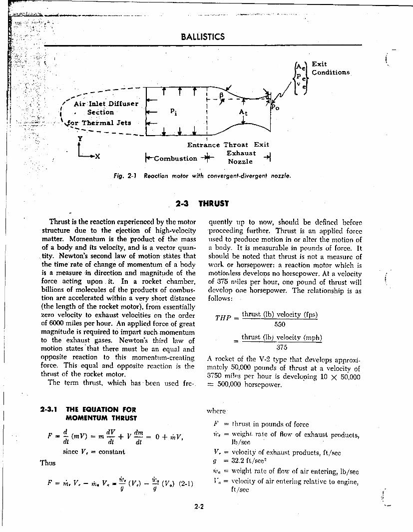
BALLISTICS
iExi
S...."k.., PeConditions
'-.,, /Air Inlet Diffuser Coniton• .:.:• : I • Section Pi!t
........... . .or Thermal Jets. LyPAir Inet Difue "
L Entrance Throat Exit
X -Combustion- ExhaustC b oNozzle
Fig. 2-7 Reaction motor with convergent-divergent nozzle.
2-3 THRUST
Thrust is the reaction experienced by the motor quently up to now, should be defined beforestructure due to the ejection of high-velocity proceeding further. Thrust is an applied forcematter. Momentum is the product of the mass used to produce motion in or alter the motion ofof a body and its velocity, and is a vector quan- a body. It is measurable in pounds of force. Ittity. Newton's second law of motion states that should be noted that thrust is not a measure ofthe time rate of change of momentum of a body work or horsepower: a reaction motor which isis a measure in direction and magnitude of the motionless develons no horsepower. At a velocityforce acting upon it. In a rocket chamber, of 375 miles per hour, one pound of thrust willbillions of molecules of the products of combus- develop one horsepower. The relationship is astion are accelerated within a very short distance follows:(the length of the rocket motor), from essentiallyzero velocity to exhaust velocities on the order THP =thrust (Ib) velocity (fps)of 6000 miles per hour. An applied force of great 550magnitude is required to impart such .momentumto the exhaust gases. Newton's third law of tmotion states that there must be an equal and 375opposite reaction to this momentum-creating A rocket of the V-2 type that develops approxi-force. This equal and opposite reaction is the mately 50,000 pounds of thrust at a velocity ofthrust of the rocket motor. 3750 miles per hour is developing 10 X 50,000
The term thrust, which has -been used fre- - 500,000 horsepower.
2-3.1 THE EQUATION FOR whereMOMENTUM THRUST F = thrust in pounds of force
F dV dm •A,7 = weight, rate of flow of exhaust products,d=-(mV)--m -+ V- = 0±nV, l/e
di dt dt ]blseesince V, = constant V, = velocity of exhaust products, ft/sce
Thus g = 32.2 ft/sec2
?i,, = weight rate of flow of air entering, lb/secF = V, - 7h. V. We (V) - 12 (V.) (2- 1) = velocity of air entering relative to engine,
g g ft/sec
2-2
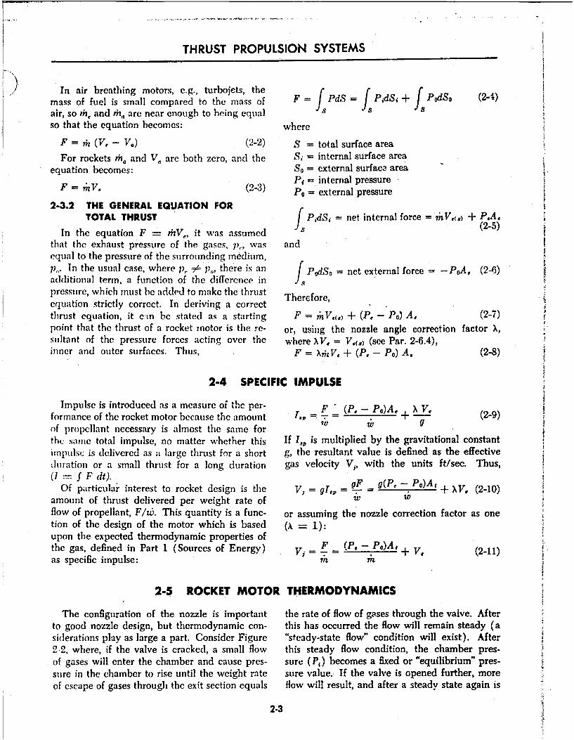
THRUST PROPULSION SYSTEMS
In air breathing motors, e.g., turbojets, the F = , f(mass of fuel is small compared to the mass of F PdS f PdSi + PdSo (2-j)
air, so th, and h,, are near enough to being equal S
so that the equation becomes: where
F = ?; (V, - V.) (2-2) S = total surface area
For rockets ,h4 and V, are both zero, and the Si = internal surface areaequation becomes: So = external surface area
Pi = internal pressureF = r"V. (2-3) P0 = external pressure
2-3.2 THE GENERAL EQUATION FORTOTAL THRUST PIdS, = net, internal force = 7hV,(,) + PA,
In the equation F = rhV,, it was assumed -(2-5)that the exhaust pressure of the gases, p,., was andequal to the pressure of the surrounding medium,p,,. In the usual case, where p1 = pi., there is an PodSo= net external force = -PoA. (2-6)
additional term, a function of the difference in Jspressure, which must be added to make the thrust Therefore,equation strictly correct. In deriving a correctthrust equation, it cm be stated as a starting F nV.() + (P.- Po) A, (2-7)point that the thrust of a rocket motor is the re- or, using the nozzle angle correction factor X,sultant of the pressure forces acting over the where XV, = V,(,) (see Par. 2-6.4),inner and outer surfaces. Thus, F = XjV, + (P. - Po) A. (2-8)
2-4 SPECIFIC IMPULSE
Impulse is introduced as a measure of the per- F (P. - Po)A, X Vformance of the rocket motor because the amount 1,, + (29)of propellant necessary is almost the same for IV g
thu same total impulse, no matter whether this If lp is multiplied by the gravitational constantimpulsc is delivered as a large thrust for a short g, the resultant value is defined as the effectiveduration or a small thrust for a long duration gas velocity V,, with the units ft/sec. Thus,(-- F dt).
Of particular interest to rocket design is the gI.9 = - - - PO)At + XV, (2-10)amount of thrust delivered per weight rate of W W
flow of propellant, F/wt. This quantity is a fune- or assuming the nozzle correction factor as onetion of the design of the motor which is based (A - 1):upon the expected thermodynamic properties ofthe gas, defined in Part 1 (Sources of Energy) V= F _ (P. - Po)A, + V. (2-11)as specific impulse: m
2-5 ROCKET MOTOR THERMODYNAMICS
The configuration of the nozzle is important the rate of flow of gases through the valve. Afterto good nozzle design, but thermodynamic con- this has occurred the flow will remain steady (asiderations play as large a part. Consider Figure "steady-state flow" condition will exist). After2-2, where, if the valve is cracked, a small flow this steady flow condition, the chamber pres-of gases will enter the chamber and cause pres- sure (P,) becomes a fixed or "equilibrium" pres-sure in the chamber to rise until the weight rate sure value. If the valve is opened further, moreof escape of gases through the exit section equals flow will result, and after a steady state again is
2-3
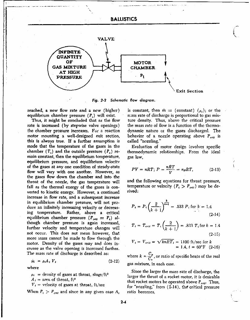
BALLISTICS
VALVE
INFJNITE
M
I j QUANTITYOF MOTOR
ATHIGHPRESSURE
\.Exit Section
Fig. 2-2 Schematic flow diagram.
reached, a new flow rate and a new (higher) is constant, then r -" (constant) (pt); or theequilibrium chamber pressure (P,) will exist. mass rate of discharge is proportional to gas mix-
Thus, it might be concluded that as the flow ture density. Thus, above the critical pressurerate is increased (by stepwise valve openings) the mass rate of flow is a function of the thermo-the chamber pressure increases. For a reaction dynamic nature or the gases discharged. Themotor mounting a well-designed exit section, behavior of a nozzle operating above Psr isthis is always true. If a further assumption is called "nozzling."made that the temperature of the gases in the Evaluation of motor design involves specificchamber (Tj) and the outside pressure (Po) re- thermodynamic relationships. From the idealmain constant, then the equilibrium temperature, gas law,equilibrium pressure, and equilibrium velocitvof the gases at any one condition of steady-state PV = nRT; P = nRT npRT, (2-13)flow will vary with one another. However, as Vthe gases flow down the chamber and into thethroat of the nozzle, the gas temperature will and the following equations for throat pressure,fall as the thermal energy of the gases is con- temperature or velocity (P, > P.,) may be de-verted to kinetic energy. However, a continued rived:increase in flow rate, and a subsequent increasein equilibrium chamber pressure, will not pro- (2 ) ý7duce an infinitely increasing velocity or decreas- P, = Pi (-- = .533 Pi for k' = 1.4ing temperature. Rather, above a critical (2-14)equilibrium chamber pressure (Peat = P,) al-though chamber pressure is again increased, T, = T,,t = T, ( •--/ .833 Ti fork = 1.4further velocity and temperature changes will knot occur. This does not mean however, that (2-15)more mass cannot be made to flow through the
motor. Density of the gases may and does in- Vi = V,, = V'knRT, = 1100 ft/sec for kcrease as the valve opening is increased further. = 1.4, t = 60°F (2-16)The mass rate of discharge is described as: where k = -C, or ratio of specific heats of the realC'pa= At V, (2-12) C
gas mixture, in each case.where Since the larger the mass rate of discharge, the
pA = density of gases at throat, slugs/ft3 larger the thrust of a rocket motor, it is desirableA, = area of throat, ft 2 that rocket motors be operated above P•,. Thus,V, = velocity of gases at throat, ft/sec for "nozzling," from (2-14), the! critical pressure
When P, > P,,, and since in any given case A, ratio becomes,
2-4
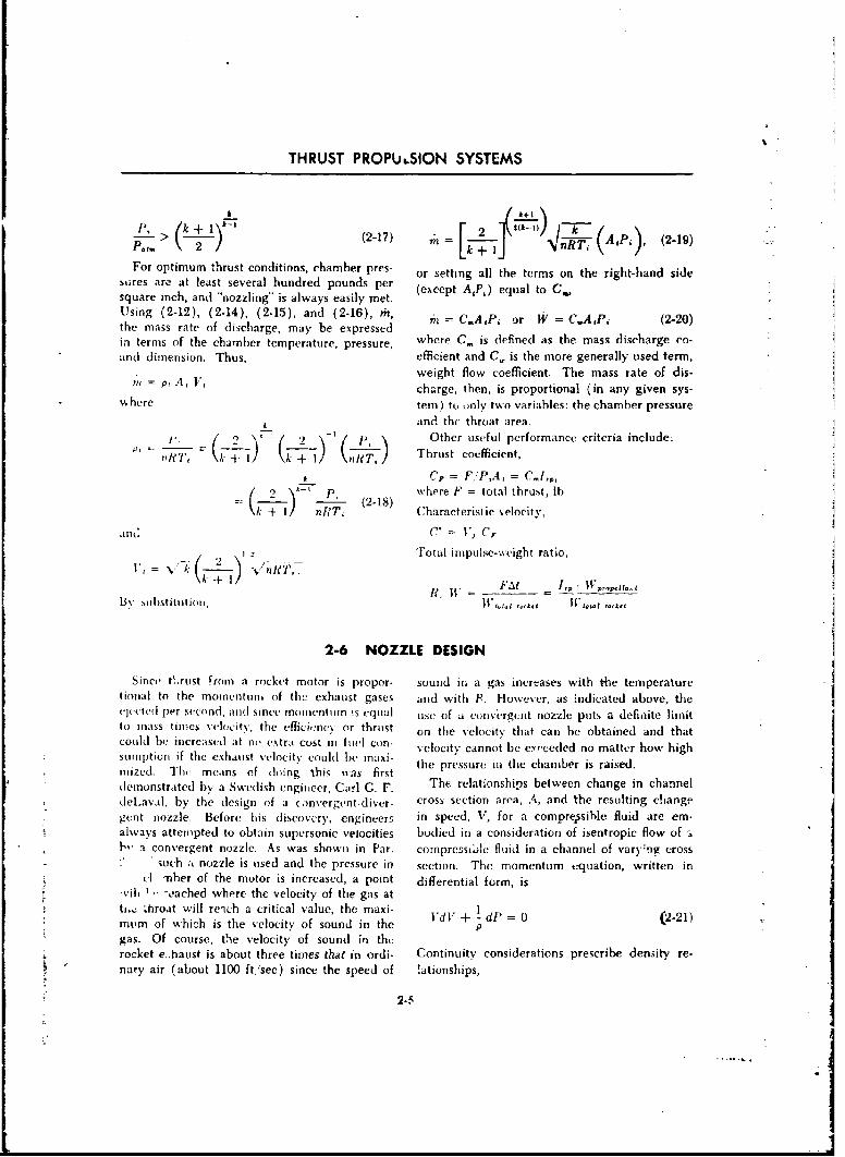
THRUST PROPU,.SION SYSTEMS
11, (k I+ L -kJ[ I----
((2417) m 2 [ (AP. (2-19)
For optimum thrust conditions, chamber pres- or setting all the terms on the right-hand sidebures are at least several hundred pounds per (except AP 4) equal to C,square inch, and "nozzling" is always easily met.Using (2-12), (2-14), (2-15), and (2-16), rn, "n = CA,P, or W = C,.A1Pi (2-20)the mass rate of discharge, may be expressedin terms of the chamber temperature, pressure, where C, is defined as the mass discharge co-and dimension. Thus, efficient and C,. is the more generally used term,
weight flow coefficient. The mass rate of dis-7,1 = p, A4 V, charge. then, is proportional (in any given sys-
w here tem) to only two variables: the chamber pressure
and the throat area.____ -@t2 (_ (9__"'/P\ Other useful performance criteria include:itP1 )~ ±1)rR, Thrust coefficient,
k+I k +- IITk_. C' = F."P,A, = C.1,,
-•) Pwhere F = total thrust, lb
k+I 'T, Characteristic ' elocity,
a nd C. = 1" Cr
2 UTotal impulse-weight ratio,
+Ft IvP-F.I _ W_,____ ,.
By .substitutionll, IW I ,W .,•A,, ° ,°
2-6 NOZZLE DESIGN
Since tLrust From a rocket motor is propor- sound in a gas increases with the temperaturetinijal to the momentumn of the exhaust gases and with B. However, as indicated above, theeJ(jted per second, and sinee momentuin is equal use of a convergcnt nozzle puts a definite limitto mass times velocity, the efficincy or thrust on the vclocity that cal be obtained and thatcould he increased at ni, extra cost in fuel con- velocity cannot be eortcedd no matter ho' high
sumiption if the exhaust velocity could be Inaxi-
inized. Thc means of doing this was first the pressure in the chamber is raised.
demonstrated by a Swedish engineer, Carl G. F. The relationships between change in channeldeLaval, by the design of a (3nvergent-diver- cross section area, A, and the resulting changegent nozzle. Before his discovery, engineers in speed, V, for a compryssible fluid are em-always attempted to obtain supersonic velocities bodied in a consideration of isentropic flow of a1, a convergent nozzle. As was shown in Par. cornpressible fluid in a channel of vary:ng crossS "such a nozzle is used and the pressure in section. The momentum equation, written in
cl -nher of the motor is increased, a point differential form, is-vih, -cached where the velocity of the gas atti.,: .hroat will reich a critical value, the maxi- lmum of which is the velocity of sound in the I'M + -dP = 0 (2-21)gas. Of course, thle velocity of sound in thurocket e..haust is about three times that in ordi- Continuity considerations prescribe density re-nary air (about 1100 ft/sec) since the speed of lationships,
2-5
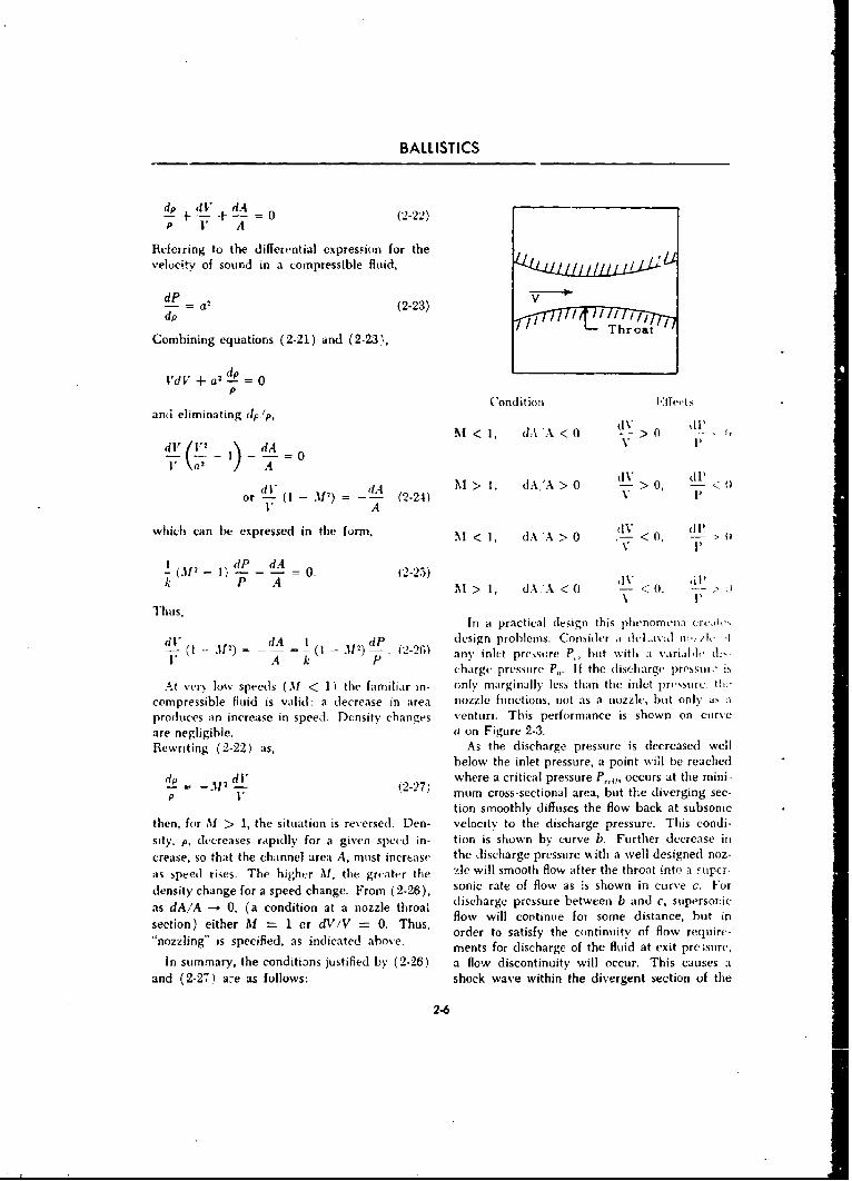
BALLISTICS
d V +dA (2-22)P 11 A
Referring to the differential expression for thevelocity of sound in a compressible fluid, /-4l
-= a'. (2-23) V
dP T roatCombining equations (2-21) and (2-23),
I'dV + aI d02 = 0p C'ondit ion .l•,I.
and eliminating dp/, Mo<, dA'A< 0 V > i
dl A'I>I, ( .A>0 > 0 <
or -- (I-A)=- (2-24) V ~ 1V A
which can be expressed in the form, M < 1, dA 'A > 0 < 0, 0- -,V 1
LP -4=k P A AM > 1, dA.A < 0 -> -- II I
Thus, ~In it practical design this phenomena c rc., tdlo - 31) = d = 1 dP t design prohlems. Consider a -le l-.v-,2l-24)c d
V A .4 k 1 any inlet pre.Asiare P but with a 'arial Iccharge pressure P,,. If the (riseharge prs", i'
At ver low speeds (.1 < 1) the familiar in- only marginally less than the inlet prssure. Olcompressible fluid is valid: a decrease in area nOAzle functions, not as a nozzle. but onlyproduces an increase in speed. Density changes venturi. This performance is shown on curveare negligible, ( on Figure 2-3.Rewriting (2-22) as, As the discharge pressure is decreased well
below the inlet pressure, a point will be reacheddp _ I d where a critical pressure P,,, occurs at the mini-P V mum cross-sectional area, but the diverging sec-
tion smoothly diffuses the flow back at subsonicthen, for M > 1, the situation is reversed. Den- velocity to the discharge pressure. This condi-sity, p, decreases rapidly for a given speed in- tion is shown by curve b. Further decrease in
crease, so that the channel area A. must increase the discharge pressure with a well designed noz-
as speed rises. The higher M, the greater the zle will smooth flow after the throat into a ýiipcr-
density change for a speed change. From (2-26), sonic rate of flow as is shown in curve c. Foras dA/A --o 0, (a condition at a nozzle throal discharge pressure between b and c, supersoiricsection) either f "- I er dV/V --- 0. Thus, flow will continue for some distance, but in
order to satisfy the continuity of flow require-"'nozzling" is specified, as indicated above. "ments for discharge of the fluid at exit pre;sure,
In summary, the conditions justified by (2-26) a flow discontinuity will occur. This causes aand (2-27) a:e as follows: shock wave within the divergent section of the
2-6
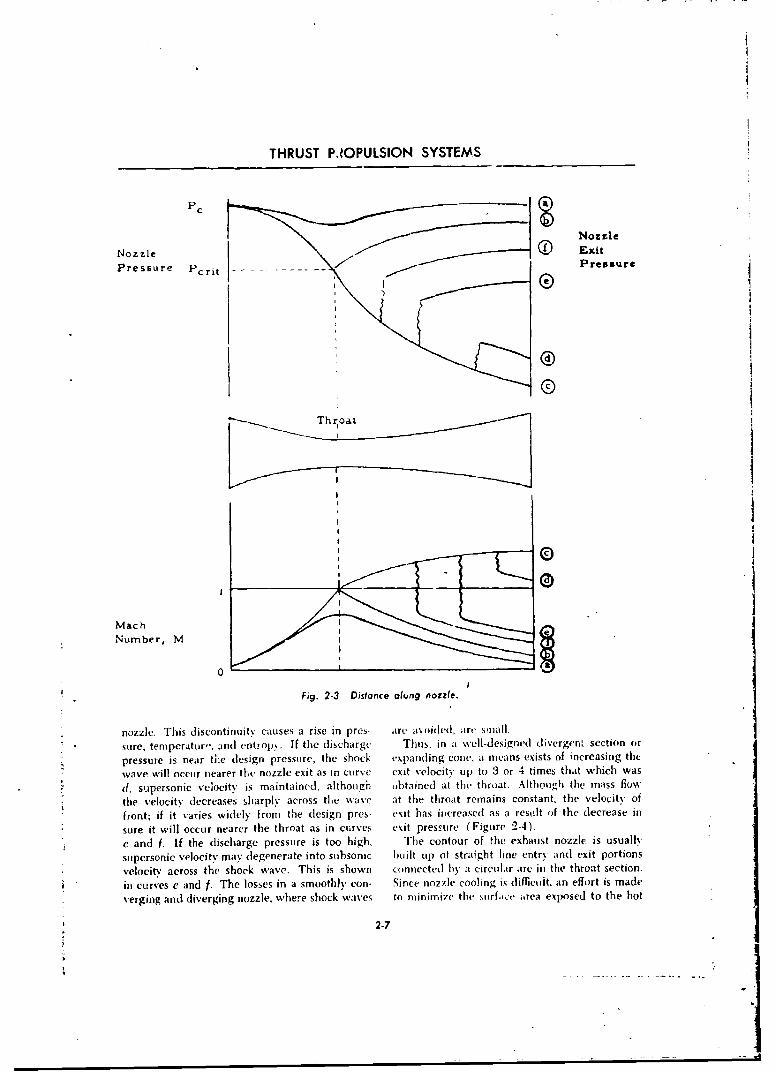
THRUST PJOPULSION SYSTEMS
PC
Nozzlie
Nozzle 0 ExitPressre PPressure
Thr oat
MachNumber, Mf
Fig. 2-3 Distance olung nozzle.
nozzle. This discontinuity causes a rise in pres- are avui(Ied, art- small.sure, temperatur". and entrop)ý. If the discharge Thus, in a well-designed divergent section or
pressure is near the design pressure, the shock expanding cone. a nicans exists of increasing the
wave will occur nearer the nozzle exit as in curve exit velocity up to 3 or 4 times that which was
(1. supersonic velocity is maintained, ilthoiiigh obtained at thv throat. Although the mass flow
the velocity decreases sharply across the wave at the throat remains constant, the velocity of
front; if it varies widely fromt the design pres- exit has increased as a result of the decrease insore it will occor nearer the throat as in curves exit pressure (Figure 2-4).e and f. If the dlischarge pressure is too high, The contour of the exhaust nozzle is usually-supersonic velocity may degenerate into subsonic built uip of straight line entry and exit portionsvelocitv across the shock wsave. This is shown connected bv' a circular arc in the throat section.
in curves u and f. The losses in a smoothly con- Since nozzle cooling is (lifDcui~t, an effort is made
verging andi diverging nozzle, where shock waves to minimize the stirfawt iirca exposed to the hot
2-7
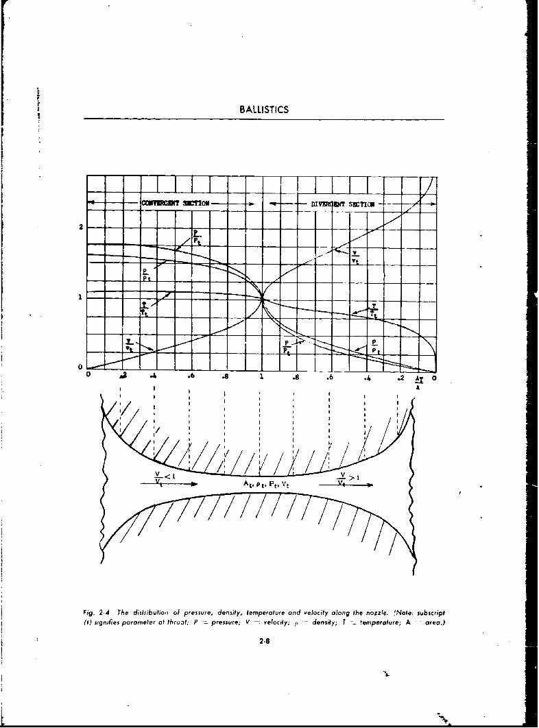
tP
tV
t BALLISTICS
I~IIEIE 'IJIDIfIi -
0 . .6 . .2 0A
At, p . Pt.t'VI I
I I II
Fig 2- h iiiui,v ol ,rsse desftmeoveadvlct ln h oze : svsr i
I ! II I I
V>
S•-" ~~At'.Pt, Pt. Vt V
Fig. 2.4 The distributio~i a1 pressure, density, temperature and velocity along the nozzle. f.Note: subscript
(f) signifies parameter at throat; P pressure; V = velocity; p - density; T temperature; A area.)
2.8
5-%
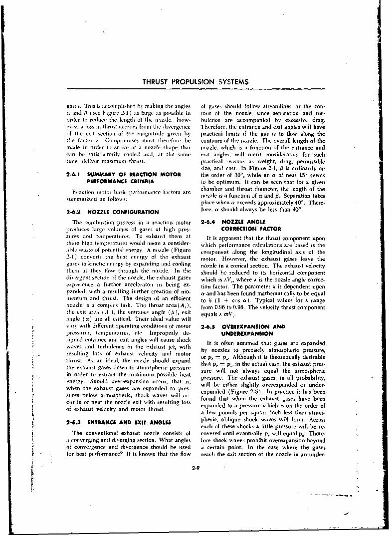
THRUST PROPULSION SYSTEMS
gases. 'I his is accomplished by making the angles of gses should follow streamlines, or the con-a and # (see Figure 2-1) as large as possible in tour of the nozzle, since- separation and tur-order to reduce the length of the nozzle. How- bulence are accompanied by excessive drag.ever, a loss in thrust accrues from the divergence Therefore, the entrance and exit angles will haveof the exit section of the magnitude given by practical limits if the gas is to flow along the
54L. .f.. :,vr x. Compromises must therefore be contours of the ;iotLie. The overall length of themade in order to arrive at a nozzle shape that nozzle, which is a function of the entrance andcan be satisfactorily cooled and, at the same exit angles, will merit consideration for suchtime, deliver maximum thrust, practical reasons as weight, drag, permissible
size, and cost. In Figure 2-1, 0 is ordinarily on2-6.1 SUMMARY OF REACTION MOTOR the order of .30%, while an a of near 15' seems
PERFORMANCE CRITERIA to be optimum. It can be seen that for a givenReaction motor barc chamber and throat diameter, the length of the
b nezzle is a function of a and 9. Separation takessumnmartzed as follows: place when a exceeds approximately 40'. There-
2-6.2 NOZZLE CONFIGURATION fore, a should always be less than 40'.
The combustion process in a reaction motor 2-6.4 NOZZLE ANGLEproduces large volumes of gases at high pres- CORRECTION FACTORsores and temperatures. To exhaust them at It is apparent that the thrust component uponthese high temperatures would mean a consider- which performance calculations are based is theable waste of potential energy. A nozzle (Figure component along the longitudinal axis of the2-1, converts the heat energy of the exhaust motor. However, the exhaust gases leave thegases to kinttic energy by expanding and cooling nozzle in a conical section. The exhaust velocitythem as they flow through the nozzle. In the should be reduced to its horizontal componentdivergent section of the nozzle, the exhaust gases which is xV,, where k is the nozzle angle correc-experience a further accelcrato1 in being ex- tion factor. The parameter A is dependent upenpandcd, with a resulting further creation of mo- a and has been found mathematically to be equalmnentum and thrust. The design of an efficient to 12 (1 + cos a). Typical values for A rangenozzle is a complhx task. The throat area(A,), from 0.96 to 0.98. The velocity thrust componentthe exit area (A, ), the entrance angle (/p), exit equals A mV0 .angle (at) are all critical. Their ideal value willvary with different operating conditions of motor 2-6.5 OVEREXPANSION ANDl)ressures, temperatures, 'etc Improperly de- UNDEREXPANSIONsigned entiance and exit angles will cause shock It is often assumed that gases are expandedwaves and turbulence in the exhaust jet, with by nozzles to precisely atmospheric pressure,resulting loss of exhaust velocity and motor
or p, = p.. Although it is theoretically desirable, thrust. As an ideal, the nozzle should expand that p, =-- p., in the actual case, the exhaust pres-the exhaust gases down to atmospheric pressure sure will not always equal the at~mosphericin order to extract the maximum possible heatenpressure. The exhaust gases, in all probability,
will be either slightly overexpanded or under-when the exhaust gases are expanded to pres. expanded (Figure 2-5). In practice it has beensures below atmospheric, shock waves will oc- found that when the exhaust ,ases have beencur in or near the nozzle exit with resulting loss ciof ehaut vlocty ad mtorthrst.expanded to a pressure v hieh is on the order of
kof exhaust velocity and motor thrust a few pounds per squart inch less than atmos-
2-6.3 ENTRANCE AND EXIT ANGLES pheric, oblique shock waves will form. Acrosseach of these shocks a little pressure will be re-
The conventional exhaust nozzle consists of covered until eventually p, will equal p.. There-a converging and diverging section. What angles fore shock waves prohibit overexpansion beyondof convergence and divergence should be used a certain point. In the case where the gasesfor best performance? It is known that the flow reach the exit section of the nozzle in an under-
2-9
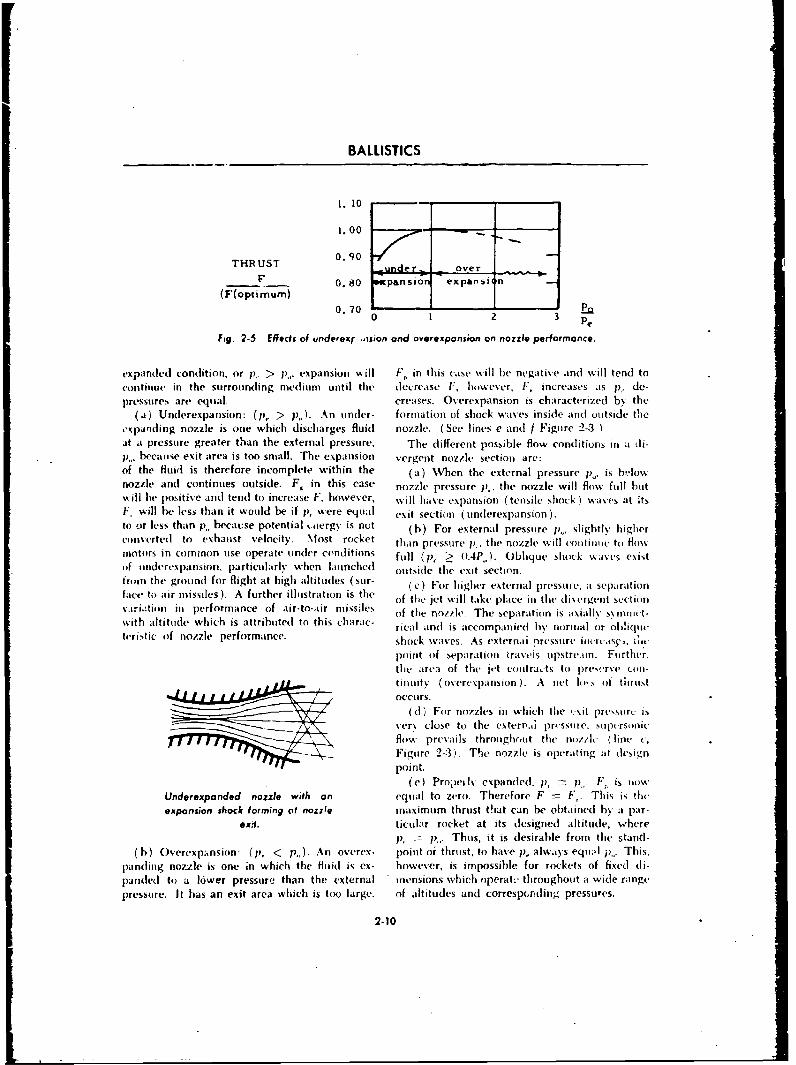
BALLISTICS
I. 10
1.00 -
THRUST 0.90 ,uner over
0.80 pans on expar)si(F(optimum)
0.70 r-0 1 2 3 P
Fig. 2-5 Efects of underex .,asion and overexponsion on nozzle performance.
expanded condition, or 1), > p,. expansion will F, in this case will be negative .nsd will tend to
continue in the surrounding medium until the decrease F; however, F, increases as p1, de-pressures are equal. creases. Overexpansion is characterized by the
(a) Underexpansion: (p, > p,,). An under- formation of shock waves inside and outside the,-xpaoding nozzle is one which discharges fluid nozzle. (See lines e and f Figure 2-3-&at a pressure greater than the external pressure. The different possible flow conditions in a di-ij. because exit area is too small. The expansion vergent nozzle section are:of the fluid is therefore incomplete within the (a) When the external pressure pI. is b-lohwnozzle and continues outside. F. in this case nozzle pressure p,, the nozzle will flow full butwill he positive and tend to increase F. however, will have expansion (tensile shock ) waves at itsF, will be less than it would be if p, were equal exit section (underexpansion ).to or less than p,, because potential ,.ergy is nct (b) For external pressure p,. slightly higherconverted to exhaust velocity. Most rocket than pressure p.. the nozzle will continue to flowmotors in common use operate tunder conditions full (p, > O.4P..). Oblique shock waves existof ondercxpansion, particularly when launched outside tile exit section.romn the ground for flight at high altitudes (sur- (c) For higher external pressure, a separation
face to air missiles). A further illustration is the of the jet will take place in the divergent sectionvariation in performance of air-to-air missiles of the nozzle. The separation is axially syintiet-with altitude which is attributed to this charac- rical anti is aceompanied iy nrital or ol iqi,
teristic of nozzle performance. shock waves. As external pressure inc.tsc,, 6wn-
point of separation traveis upstream. Further.
the area of the jet contra-tx to pre,('rve con-tinuity (overcvpansion). A net lo., of th-rust
occu rs.(d) For nozzles in which the ,-sit pressure is
vers close to the exterodi pre'ssure, supursonicflow prevails throughouut the nozzlh (line c,Figure 2-:.3). The nozzle is operating at designpoint.
(e) Propiell expanded. ) =1. p. F. is nowUnderexpanded nozzle with an equal to zero. Therefore F = F,. This is thie-expansion shock forming cit nozzle maximum thrust that can be obtained by a par-
exit. ticulrr rocket at its designed altitude, wherep, _= p,. Thus, it is desirable from the stand-
(b) Overexpansionn (p, < p.,). An overex- point oi thrust, to have ;, always equod p,. This.
panding nozzle is one in which the fluid is ex- however, is impossible for rockets of fixed di-
panded to a Idwer pressure than the external inensions which operat2, throughout a wide rangepressure. It has an exit area which is too large. of altitudes and correspcrnding pressures.
2-10
THRUST PROPULSION SYSTEMS
2-6.6 EXHAUST VELOCIrY the ideal cycle efficiency of constant pressure
The basic thermodynamic relationship for ex- engine cycle operating between pressures p, andhaust velocity. V,_ based on isentropic flow p, and the gas constant R1, for the fluid, is re-above the critical pressure ratio is. placed by the universal gas constant R, divided
by the average molecular weight of the fluid
= - ()*J(exhaust products) WI
JiTUsing perfect gas law relationships, this may Since V .- f .. " the greatest promise for
be rewritten as, high velocity of exhaust an6 highest velocity
thrust lies in use of fuels which offer prospects of
V, 41. WTIhighest combustion temperatures (within limitsN, R"T, [ -- () of motor wall strength) and low average molec-
ilar weights of exhaust products The so-called=new, exotic, or "zip fels described i2y Part
. _ - iT, I- I (Sources of Energy) arte specihcaliv tailoredk 'u L2-28) to meet this criterion. Fuels containing free radi-
cals offer great promise in this area. Such fuelswhere T, and p, refer to chamber '.or stagna- of fluorine and boron compounds, now under en-titan) conditions. Thus, gineering development, offer specific impulse
ratings in excess of 400 seconds, in comparison4 = - I J1_ with present standards of 350 seconds for liquid
where propellants and 220 to 280 seconds for solid pro-pellants. For outer space travel, the same cri-terion is tlhe basis tor solar, nuccva;, and ionic
_ - (,� r proldlsion systems with pr,,nise!, )f specific im-S1 \jk/ pulse ratings in excess of ISMO seconds.
2-7 SOLID PROPELLANT ROCKETS
The bimplest of reaction motors in design is tomperatures (over 150'F t. the gram may be-the solid propellant rocket motor. It is easy and come plastic and at low temperatures belowinexpensive to construct. In this type of rocket 2O0F). the grain may become britttc. Either ofthe combustion chamber contains the solid pro- these conditions may cause erratic burning orpellant. Ballistite in stick form or cast Thiokol explosion, since at higher temperatures they burnmight he used in a typical case. Ignition of more rapidly, and when brittle, they break withthis charge by an igniter causes rapid burning resulting increases in initial burning surface.and thie rapid liberation of hot gases. Rockets Recent development has appreciably improvedof this type generally have high specific propel- this temperature sensitivity.lant consumption and deliver great thrust but Since a solid propellant rocket requires a rela-generally of only short duration. Internal pres- lively heavy casing, the ratio of the weight of tiesures are often high- popellant to the total weight of the rocket is
For instance, ordinary solid propellants re- low. approximately 0.7. To obtain long rangesquire pressures up to 2000 psi in order to and to carry large pay loads, a large percentage ofsustain combustion, and the exhaust gas tem- *he total weight of the rocket must be propellant.
Speratures reach 4000 to 5000'F. These high Recent developments of internal burning grainspressures and temperatures necessitate relatively with a slow rate of burning and low operatingthick motor walls to contain them. Soli-l pro- pressures should help to overcome these unde-peliants are susceptible to temperature extremes. sirable features. Solid propellant rockets have
t This is particularly true of ballistite. At high in recent years shown increasing promise for use
02-11
S
-- -- - ,'- Ik -
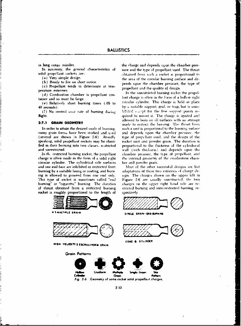
BALLISTICS
in long range missiles. the charge and depends upon the chamber pres.In summary, the general characteristics of sure and the type of propellant used. The thrust
solid propellant iockets are: obtained from such a iocket is proportional to(a) Very simple design. the area of the circular burning surface and de.(b) Ready to fire on short notice. pends upon the chamber pressure, the type of(c) Propellant tends to deteriorate at tern- propellant and the quality of design.
perature extremes. In the unrestricted burning rocket the propel-(d) Combustion chamber is propellant con-(aad) Combustion chamberg isplant charge is often in the fi)rm of a hollow right
tainer and so must be large.(e) Relatively short burning times (.05 to circular cylinder. This charge is held in place
40 seconds). by ý, suitable support, grid, or trap, but is unin-(8) No control uvcr rate of burning d, ig ., -pt for the few sunport points rv-
flight. quired to mount it. The charge is ignited andallowed to burn on all surfaces with no attempt
2-7.1 GRAIN GEOMETRY made to restrict the burning. Thei thrust fromtIn order to attain the desired mode of burning, such a unit is proportional to the burning surface
many grain forms have been studied and uz:ed and depends upon the chamber pressure, the(several are shown in Figure 2-6). Broadly type of propellant used, and the design of thespeaking, solid propellhnt rockets may be classi- rocket unit and powder grain. The duration isfled in their burning into two classes: rtstricted proportional to the thickness of the cylindricaland unrestricted, wall (%veb thickness) and depends upon the
In th. restricted burning rocket, the propellant chamber pressure, the type of propellant. andcharge is often made in the form of a solid right the internal geometry of the conibustion chaTis-circuiar cylinder. The cylindrical side surfaces ber and powder grain.and one end face are inhibited or restricted from Most of the other successful designs are butburning by a suitable lining or coating, and burn- adaptations of these two extrenies of charge d-.ing is allowed to proceed from one end only. sign. The chargkrs shown on the upper left inThis type of rocket is sometimes called *end Figure 2-6 are t-suallv nnrestrictd, the twoburning" or -cigarette" burning. The duration charges on the upper right hand side are re-of thrust obtained from a restricted burning stricted burning and semi -restricted burning, re-rocket is roughly proportional to the length of spectively.
4 5CdSALTIPLr GRAIN SitNGLI GRfAIN-O•lMlNiNG
COME GI CYLINDERg"IHiH VELOcITYY25CRUGIVRM GRAIN
Groin Pattems
Fig. 2 6 Geometry of some rocket solid propella~it charges.
2-12
THRUST PROPULSION SYSTEMS
2-8 SPECIAL CHARACTERISTICS OF THE SOLID PROPELLANT ROCKCET
rhere are some special characteristic, of solid (b) Temperature sensitivity and limits.propellant rockets which should be ex-)Iained in (c) Combustion limit.order to fully understand the major limitations of (d) Pressure limit.the rocket propellants now in use. These charac- (e) Physical changes in storage.*e~istics are: The significance of each of these terms will be
(a) Mode of burning, discussed below.
2-8.1 MODE OF BURNING about the best shape attainable, A typical time-In describing a rocket assembly containing a pressure relationship of a rocket is shown in
solid propellant, it is not sufficient to refer only Figure 2-7. The initial pressure rise within theto the propellant compostion to determine its motor chamber may be comparatively slow.characteristics. Information must also be given Once having reached its peak, it is inaintainedas to the manner in which the fuel burns undei at a constant level of the order of 1000 to 5000a given set of conditions established to gixe the psi over an appreciable length of time, oi at least
desired performanr.c. For rocket propellant cal- falls olfonly very slowly untilthe charge is com-culations, the rate at which the surface of the pletely consumed. The order of time varies frompropellant recedes in a direction normal to itself a few seconds up to a minute or more. The limi-dw, ing the burning, is designated as the rate of taticns upon the maximum pressure are governedburning and is usually expressed as inches per by the strength of the rocket tube and the maxi-second. The burning rate is dependent upon the mum mass rate of discharge which can be per-chamber pressure and increases as the pressure mitted for a given end use. The pressure within
increases. The range of burning rates at pres- the rocket can be readily changed by changes insures of 2000 psi for modern solid propellant: propellant composition as well as burning surface.varies between the limits of I to 2 inches per The lower and upper limits in pressure are gov-second. erned by propellant characteristics which will be
A comparisen between the pressure-time re- discussed later.lationship in a gun and in a rocket will assist in 2-8.2 fEMPERATURE SENSITIY. fTunderstanding the pressure problem. In the coe AND UMITSof a cannon, the pressure within the gun chamberrises very rapidly to a peak pressure of approxi- The rate at which a solid rocket fuel bums v,mately 36,000 psi and, as the projectile travels markedly affected by thetemperatureof the fuel.down thi bore of the gui,, the pressure falls off This change in the burning property will vaiyquite rapidly. The time interval between the with each formulation and even, though to azero points of pressure is of the order of a few lesser degree, with the form of grain. To designmilliseconds. Generally, a change in ballistic a rocket motor properly a knowledge of theperformance of a cannor• propellant is limited change in burning rate with temperature mustto minor changes in dimensions. This is due to be available to the designer.the fact that in most instances both the weight If a series of identical rockets are fired afterof projectile and gun are fixed so as to prevent being eor.ditioned at various temperatures, it willmajor changes in propellant design from being be found that as the conditioning temperatureeffective. Rockets, on the othe, hand, are some- is increased a.bove normal (70'F), the pressurewhat more versatile and permit major changes obtained within the rocket motor, when it isin propellant design and minor changes in motor fired, increases; and as the temperatur of con-design to gie the desireu performance, ditioning is lowered, decreased pressures a, e ob-
Ideally, the time-pressure curve in a rocket tained. Since, all other things being equal, themctor should be rectangular; a "plateau" is rate of burning is dependent upo,. the pressure
2-13
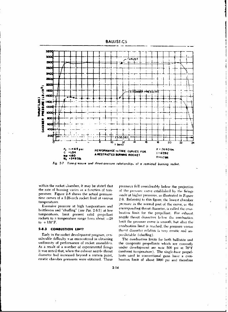
BALLISTiCS
mRLYST -
- - - ~ JKL
__ __ __
1T Joe(~
2 ~ 4 . e 1 2 1 1 0 ~ 2
p. sJ~59 gjF -
2 660ibs.C *L$4 CUVS-~I*62912bp *ISO A RESTRICTED OSL.I.4 ROCKETIf*.7WC .R349.5ft
Fig. 2.7 Time-p -essure and thrust-oressure relationshipa of o restricted burning rocket.
within the rocket .;hamber, it may be stateri that pressures fell considerably below the projectionthe rate of burning varies as a function of tern- of the pre~surc curv6e established by the firingsperature. Figure 2-8 shows the actual pressure- made at highier pressures, as illustrated in Figuretime curves of a 3.25-inch rocket fired at various 27-9. Referring to this figure, the lowest chambertemperatures. o-reSSUTe in tenormalpatothcuvrte
Excessive pressure at high temperatures and th patoih uvo hbrittleness and "chuffing" (see Par. 2-8.3) at low borrstiondligithforath propelnt.r For cled haustltemperatures, limit present solid propellant utolitfrthpoela.Frexusrockets to a temperature range from about -20 nozzle throat diameters below the combustionto + 1200F. limit the pressure curve is smooth, hut after the
combustion limit is reached, the pressure versus2-8.3 COMBUSTION LIMIT throi-t diameter relation is very erratic and un-
Early in the rocket development program, coni- predictable (chuffing).siderable difficulty was encountered in obtaining The combustion limits for both ballistite anduniformity of perfomiuance of rocket assemblieýs, the composite propellants which are currentlyAs a result of a number of experimental firings under development are near 500 psi at 70*Fit was noted that, when the exhaust nozzle throat (ambient temperature). The single-base propel-dliameter had increased beyond a certain point, lants used in conventional guns have a comn-erratic chamber pressures were obtained. These bustion limit of about 5000 psi and therefore
2-14
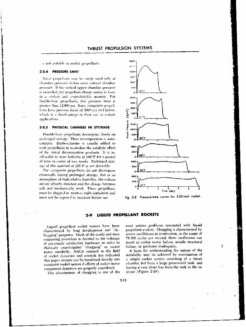
THRUST PROPULSION SYSTEMS
C not sitital)h' as rocket propellants.
"A-8.4 PRESSURE LIMIT VW -
Sot.,e prope'lants may he safely used only at 'so,-
chamber p)ressures below some critical chamber 00-
pressure. If the critical upper chamber pressure soo-IS exceeded, the propellant charge seems to burn o- '- -
ii ai viit ,and ,: pred ictabe manner. Fordouble-base propcllants, this pressure limit is /Soogreater than 12,(XXt psi. SomIt composite propel-
lants lihave pressure limits of 3W)1 rF,-i and below,
xhich is a disa(clantage in their use in certain sapplications.
2-8.5 PHYSICAL CHANGES IN STORAGE y_
Douhle-base propellants decompose slowly on oSoprolonged storage. Their decomposition is auto- s0" •"
catalytic. Diphenylamine is usually added to
stich propellants to neutralize the catalytic effect
of the initial decomposition products. It is in- S
advisable to store hallistite at 140'F for a period
of time in excess of two week5_ prolonged stor- -&M
ag,2 of this material at 120`F is not desirable.
The composite propellants do not decompose 0 t ,,
chemically during prolonged storage; but in an _00_
atmosphere of high relative humidity, the sodium - --0nitrate absorbs moisture and the charge becomes \soft and mechanically weak. These propellants 09must be shipped in -noisture tight containers and ,
must not be exposed to moisture before use, Fg. 2.8 Pressure-time curves for 3.25-inch rocket.
2-9 LIQUID PROPELLANT ROCKETS
Liquid propellant rocket motors have been most serious problems associated with liquid
characterized by long development and "de- propellant rockets. Chugging is characterized by
bugging" programs. Much of the costly and time severe oscillations in combustion, in the range of
consuming procedure is devoted to the redesign 75-300 cycles per second; these oscillations can
of previously satisfactory hardware in order to result in rocket motor failure, missile structural
eliminate unanticipated "chugging" or rocket failure, or guidance inadequacy.
motor instability. NACA research in the field A basis for understanding the nature of the
of rocket dynamics and controls has indicated instability may be achieved by examination of
that paper designs can be translated directly into a simple rocket system consisting of a thrust
successful rocket motors if effects of rocket motor chamber fed from a large pressurized tank, and
component dynamics are properly considered. having a very short line from the tank to the in-
The phenomenon of chugging is one of the jector (Figure 2-10).
2-15
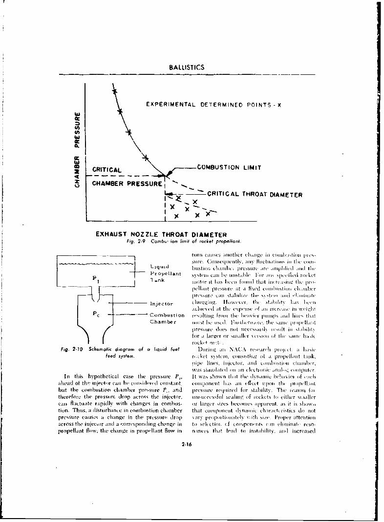
BALLISTICS
EXPERIMENTAL DETERMINED POINTS -X
M CRITICAL -CO0MBUSTION LIMIT49x CHAMBER PRESSUREI
CRITICAL THROAT DIAMETERx
Ix
EXHAUST NOZZLE THROAT DIAMETERFig. 2-9 Combu, ion limit of rocket propellant.
turncu iises ainothier chlioige iii cnlibitioi 1)1ics-__________________________suire. Consc pitIN ;1h. a% filictiitniiil intll .h (1)111-
Liquid Illitno, cill. .1ressurc irc allijplifilui iiii t~liPropellant ~Stiii Ciiil 1W l1Dtii (iIV. For amo sp~cificd rockiet
lan lioctor it Iiais btto foiiiid that iioreaisilu tile( pro-peiiaiit pressure it a fised combiialtioji cleaiilir
call11 k01 staihili'.e the %stvsti andi~l ljifiiiatc-ý4 Injector (li.gig ~\eL.tlil st.thi!itv l.as ltii
idcli jesed a t tlici e\pen sc of mi iO(-rcaw ill %\i jtdlitPC -- Combustion i-'siiting Iroiii the leicvjic phiuips dliii' liint's thait
C~harnbe r lillst lie UNC.1. Fiviiuicriinow. the sai,ii. prop)ixlidt
7 pre~ssure doces not necessaitlx restlt in stalulit\I ~~for at larger or siiiaiII.r xursioii of tli. sa.ii ha-acI ~~roAckt i-t
Fig. 2-10 Schematic diagrarr of a liquid fuel Diiriniz an NAC.\ resvar' tl pi-uj it a 1)iasiu
feed system. re-ket tste~in, coiisistiti,e1o it propellmiit tanik,
-xas siinnlateil oil dii cluctroiiic inail, (.llplitcr.
In this hypothetical case the pressuire P,. It w~as shlo,,%n thi-it the dvisrialic hellivioi of ea;chaihead of ti w injecto r can h1 consid(ereud constant- et I ponen t IM S al ffec2(t upon)1 theIn propeliiIit
bu~t the combustion chamber pressure P. and pressure requiired for stability. The evasoll folthcreforc: the pressurc drop across thc injector, uninsccvsshil scalingt. oif inckcts to either si-iallercan fluctuate rapidly' with changes in combus- or Ilarger sizes, becomnes apparent. as it is show"i
ti on. Thus, a disturbance in combustion chamnber that coinponent dynamic chairatctristics dto notpressure causos a change in the pressure drop s-arý proportionatciy vwith size, Froper attentionacross the injector and a rorrcspondling chi'nge in to Nece-tioi. (,f coitiponents can eliminate ruso-dpropellant flow; the change in propellant flow in ninces that lcad to instabiliity. atltl increased
2-16I
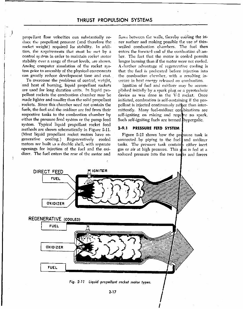
THRUST PROPULSION SYSTEMS
"plropellant flow velocities can substantially re- rluw'ss betwecn tie wvals, thereby cobiing the iri-duce the propellant pressure (and therefore the ner surface and making possible tLe use of thin-rocket weight) required for stability. In addi- walled combustion chambers. The fuel thention, the ro(Iuirements that must be met by a enters the forwardl end of the combiustion c&.un-control sy.;tem in order to maintain rocket motor ber. The fact that the motor is cooled permitsstability ever a range of thrust levels, are shown. longer burning than if the motor were not cooled.Analog computer simulation of the rocket sys- A further advantage of regenerative cooling istern prior to assembly of the physical components that the fuel is preheated before injection intocan greatly redluce development time and cost. the combustion ch.wmber,, with a resulting in-
To overcome the problems of control, weight, -rcarse in hent energy released on combustion.and heat of burning, liquid propellant rockets Ignition of fuel and oxidizer may be accom-are used for long duration units. !n liquid pro- plished initially by a spark plug or a pyrotechnicpellant rockets the combustion chamber may be device as was done in the V-2 rocket. Oncemade lighter and smaller than the solid propellant initiated, combustion is self-sustaining if the pro-rockets. Since this chamber need not contain the pellant is injected continuously ratl~er than inter-fuels, the fuel and the oxidizer are fed from their mittently. Many fuel-oxidizer con binations arerespective tanks to the combustion chamber by self-igniting on mixing and requ ,c no spark.either the pressure feed system or the pump feed Such self-igniting fuels are termed hypergolic.system. Typical liquid propellant rocket feedmethods are shown schematically in Figure 2-11. 2-9.1 PRESSURE FEED SYSTEM(Most liquid propellant rocket motors have re- Figure 2-12 shows how the pr ýssure tank isgenerative cooling.) Regeneratively cooled connected. by pip;ng to the fuel and oxidizermotors are built "s a double shell, with separate tanks. The pressure tank contain - either inertopenings for injection of the fuel and the oxi- gas or air at high pressure. This as is fed at adizer. The fuel enters the rear of the motor and reduced pressure into the two ta ks and forces
DIRECT FEED IGNITER
REGENERATIVE (COOLED)
Fig. 2-11 Liquid propellant rocket motor types.
2-17 /
I
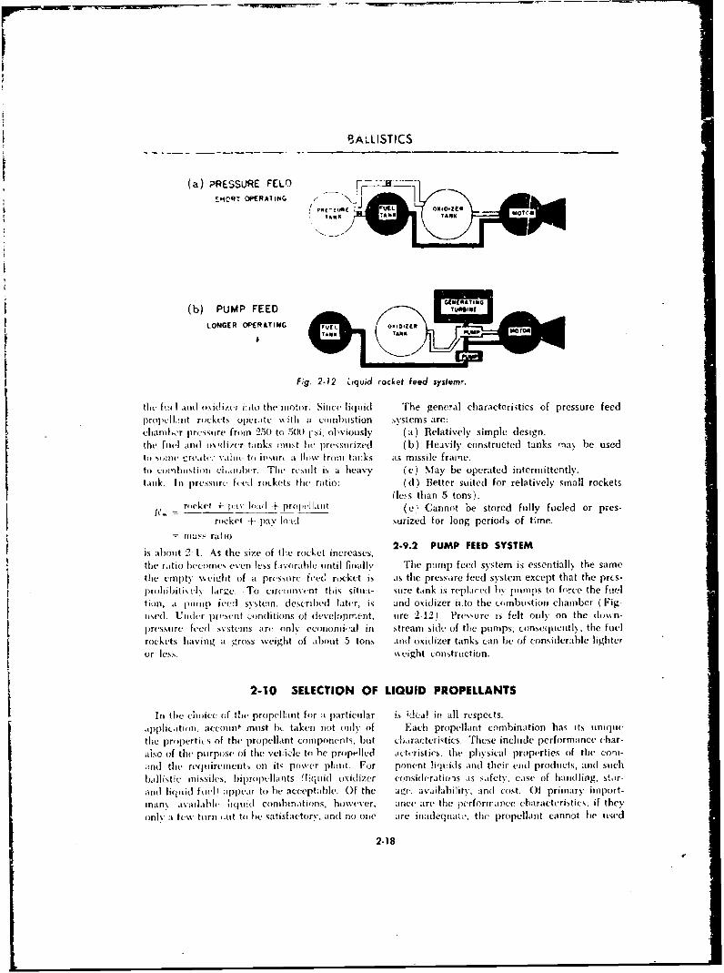
SALLISTICS
(a) PRESSURE FELO r- -
SMCRT OPERAIIhG /N j
TANK U ITTN
(b) PUMP FEED T*11
LONGER OPERAT'ING ®rufl L OxII'ZE
Fig. 2-12 Liquid rocket feed system.
thL fý!t I .1nti ouxidlizer inito the- miotor. Since liqulid The general characteri sties of pressure feedproplintL rockets operAte with ;I co iidiistion systems are:claialwr prc tire from 250) to 5W(1- si, ob~viously (a) Relatively simple design.the fuel and~ {)\'(itcr tank,; must lbe pressurized ( b) Heavily constructed tanks oiaN be usedto somie -creatcr Nale- to jpsiur :I fli~w fromi tacks ats missile frame.to comi~i'iiis ui cioidwlr. The re~iilt is a heavy (c) May be operated intermittently.tank-. In pre~ssure feed rockets the ratio: ( d ') Better suited for relatively small rockets
(less than 5 tons).
-rockel 4-11 paY l'l +4' 2LrP 1 __otkt (e) Cannot 'he stored fully fueled or pres-rockel + pay load surized for long periods of time.
mas:s ra tio2.9.2 PUMP FEED SYSTEM
is about 2-1. As the size of tlhe rocket increases,the ratio b econes even less fi o rable unil t in6mal lv The pumop feed systemn is essentially the same
tlie empty weozit ofi a prcssure teec! rocket is as the presso re feed sy stem except that the prf s-prolo Ibit is el larlge. To circuinvent ti is itiiri- suire tank is replace-d by pumirps to force the fuiel
t ion, at p111mim feed sy.stemn, described Later, is and oxidizer ii to the combustion chamber ( Fig-used- Uzider present c':mnddions of developrrierut. mire 2-12)- Pressure is felt only~ on the dust i-pressumre feed svstemns arr only ecumnonuiial in streamn side of the pumps; consequcittl%> the fuel
rockets having at gross wxeight of aibou1 t 5 tons and oxidizer tanks can be of cons iderable lighter
or less. %eight construction.
2-10 SELECTION OF LIQUID PROPELLANTSIin the unoice oif thie propell;int for -i particular is d'ea! in all respects.upphicatiomi. account must bi- taken niot only of Each propellant combination has its uniquec
the properties of the propellant commponents, hut characteristics, These include performance char-also of thme purpose of the vaticle to be propelled acterist irs. the phy .sical properties of the conii-
-Ind the reqtiliremnents on itý power plait. For ponent !iquidls andi~ their end products, aind sutchb~ilhist'e missiles, bipiropcelaviits (liqtiid oxidizer consideratio-is as safety, ease oif handling, stor-a~nd liquidi~ foul1 appear to be acceptable. Of the age. availahi lity .' nd cost- Of primary import-manx available hiquiid combinations, however. ance are the perforipaoe characteristics, if they
un~y at tew toirn (.ut to hie satisfactory, andl no oneC are inadeqtiatc% the [propellaint cimnnct he used
2.18

THRUST PROPULSION SYSTEMS
no matter how desirable its other characteristkcs the tank structure can then be made smaller andmay be. Furthermo-c, the characteristics that do lighter and the liquids will also be easier tonot directly affect pcrformancc can often be ptimp. Other desirable propellant properties in-compensated for or modified. For instance, if a elude rapid and reliable ignition of the mixture,liquid component has a high freezing tempera- high rate of reaction, low vapor pressure, andture, thus complicating its use in low-temperature low freezing point. Among the properties creat-regions, it may be possible to add some substance ing possible hazards are chemical instability,that will lower the freezing point and yet not corrosivity, flammability, and toxicity. In viewintroduce unwanted side effects. Again, the cor- of these many restrictions, one can see why therosive action of a highly active !propellant com- search for suitable liquid combinations is a majorponent may be rendered negligible if tanks and problem of rocket research.pipelines made of special materials are used. Significant advances with high-energy pro-
It has been shown that the specific thrust may pellants may he forthcoming if solutions can bebe increased by raising the temperature of the found for the engineering problems of adaptingcombustion products in th. chamber, and by such propellants to rocket applications and ofreducing the weighted average of their molecu- producing them on a commercial basis, at accept-lar weights. A high gas temperature can be able prices. For ICBM propulsion, significanto•tained by using a propellant mixture that increases in performance and energy would re-vie .lds a large quantity of heat per pouud of suit if reliable and practical rocket power plantsmixture. The average molecular weight of the could be developed for even the commonlycombustion products is determine( both by the known high-energy propellants, such as liquidnature of the oxidizer and the fuel, and by the fluorine and liquid hydrogen.ratio in which they are mixed. To reduce the rate of transfer of heat through
The specific thrust will also be iowerc r if the the combustion chamber walls (an acute problemcombustion gases dissociate into simpler mole- ini rocket engine design), several different meth-cules and atoms, because the dissociation requires ods have been devised and are in use. Oneenergy and thus reduces the amount available for scheme, still uiader investigation, is to employ anconversion into the translational kinetic energy oxidizer-fuel combination that will deposit onof the exhaust stream. Where tests indicate the inner chamber wall an inert coating capablethat effects of dissociation are appreciable, a of providing good thermal insulation and also ofchange can be made either to a propellant having withstanding the scouring action of the hot gasmore stable reaction products or to a lower gas flow. The graph in Figure 2-13 illustrates thetemperature. temperature gradients to be expected in a regen-
In addition to these basic requirements the eratively cooled thrust chamber provided withdensities of thle propellants should be high, for such an inert coating.
2-11 PROPELLANT UTILIZATION
Propellant utilization is a problem that be- tolerances, may consume one propellant compo-comes important when a missile is being fired nent at a relatively faster rate. Thus, when thisfor maximum range. The problem is to insure component is completely consumcd, a portion ofthat the maximum amount of propellant available the other one remains unburned. The effects ofto the rocket engines is consumed by them and to residual propellant can be drastic. For instance,design the propellant feed system so that a a rough calculation shows that if one percent ofminimum amount of propellant is trapped and the initial propellant weight remains unconsumedhence unavailable for consumption. For the bi- in a vehicle designed to have a thrust-cutoffpropellant rocket engines of c'urrent ballistic speed of 25,000 ft/sec, the range will be reducedmissiles, the problem is accentuated since the by about 600 nautical miles. Moreover, to main-engines, LOecause of various system and trajectory tain this cutoff speed of 25,000 ft/sec when one
2-19
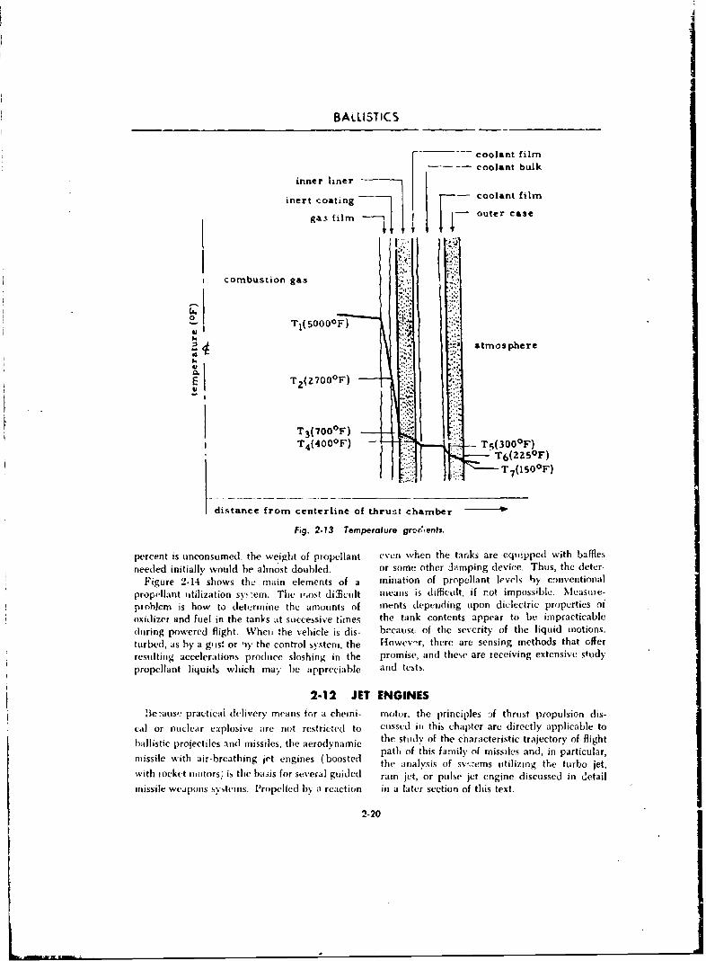
BALLISTICS
V coolant film-- coolant bulk
inner liner-
inert coating -coatfl
gas film -iouter case
I combustion gas
0 ~T1 (5000 0 F)
Satmosphere
E T2 (Z?00 0 F)
T3 ( 700('F)T4(400 0F) - j 30F
distance from centerline of thrus, chamber 10
Fig. 2-13 Temperature grt~c,,enh.
percent is uneonsumed- the weight of propellant even when the tanks are equipped with bafflesneeded initially would he almost doubled. or some other Jamping device. Thus, the deter-
Figure 2-14 shows tho main elements of a mination of propellant levels by conventionalpropellant utilization sy-e m. The i',ost difflcilmt means is difficult, if not impossible. Measure-problem is how to det4ermine the amounts of mnrnts depending upon dielectric properties ot
oxidizer and fuel in the tanks at successive times the tank contents appear to be impracticable(luring powered flight. When 'he vehicle is dis- bccatisf of the sevcrity of the liquid inotions.turbed, as by a gi is. or I'y the control system, the H-owev,?r, there are sensing methods that offerresulting accelerations produce sloshing in the promise, and these are receiving extensive studypropellant liquids which may be appreciable and tests.
2-12 JET ENGINESlle~auseý practical delivery means for a cheini- motor, the principles If thrust propulsion dis-
cal or nuclear explosive are not restricted to cussed in this chapter are directly applicable toballistic poetlsadmsietearyn ic the study of the chiaracteristic trajectory of flight
proicties nd isslestheaerdynmic path of 'this family of missiles and, in particular,missile with air-breathing jet engines (boosted the analysis of sv,;ems utilizing the turbo jet,with iocket imotors, is the basis for several guided ram jet,'or pulse jet engine discussed in detailmissile weapons systems. Propelled by a reaction in a latter section of this text.
2-20
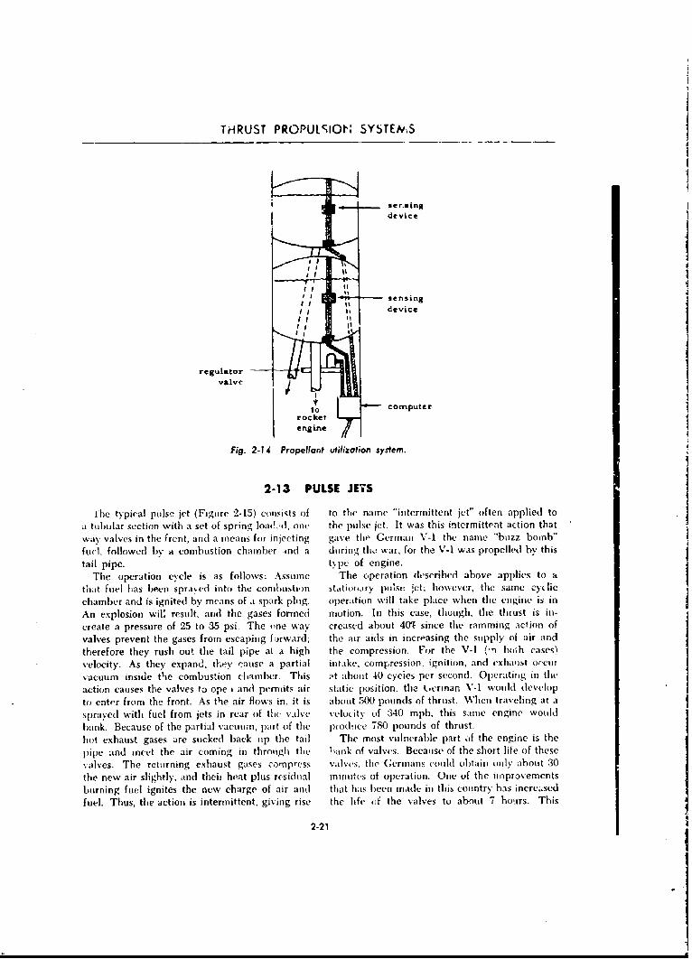
THRUST PROPULSION SYSTEMS
sensingdevice
regulatorvalve
tocomputerrocket
Fig. 2-14 Propellant utilization system.
2-13 PULSE JETS
The typical pulse jet (Figurc 2-15) consists of to the name "intermittent jet" often applied to
a tubular section with a set of spring loadld, one the pulse jet. It was this intermittent action that
way valves in the frent, and a means for injecting gave the German V-I the name "buzz bomb"
fuel, followed by a combustion chamber :nd a during th• war, for the V-I was propelled by this
tail pipe. tpc of engine.
The operation cycle is as follows: Assuume The operation described above applies to a
that fuel has been sprayed into the combt)ustion stationlary pulse ;ct; howýever, the same cy lic
chamber and is ignited by means of a spark plug. operation will take place when the engine is in
An explosion wil result, and the gases forme•d motion. In this case, though, the thrust is in-
create a pressure of 25 to 35 psi. The one way creased about 401 since the ramming aclion of
valves prevent the gases from escaping firward; the air aids in increasing the supply ol air and
therefore they rush out the tail pipe at a high the compression. For the V-I (-n hoth cases)
velocity. As they expand, they' cause a partial intake, compression, ignition, and exhast o,.enh
vacuum inside thIe combustion chamber. This ,,t about 40 cycies per second. Operating in the
action causes the valves to ope i and permits air static position. tho ucrman V-1 would develop
to enter from the front. As the air flows in. it is about 500 pounds of thrust. When traveling at a
sprayed with fuel from jets in rear of the valve velocity of 340 mph, this same engine would
bank. Because of the partial vacumn, part of the produce 780 pounds of thrust.
hot exhaust gases are sucked back up the tail The most vulnerable part if the engine is the
pipe and meet the air coming in through the bank of valves. Because of the short life of these
valves. The returning exhaust gases compress valves, the Germans could obtain only about 30
the new air slightly, and thei heat plus residual minutes of operation. One of the improvements
burning fuel ignites the new charge of air and that has, been made in this country has increased
fuel. Thus, the action is intermittent, giving rise the lifte of the valves to about 7 hboIrs This
2-21
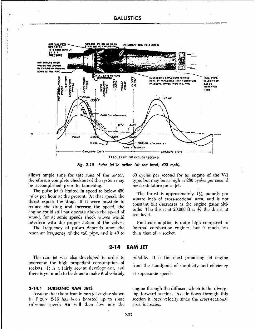
BALLISTICS
AIR VALVES PARK PLUG uszo TO COMBUSTION CHAMBERINIEYR"ITTANTLYV
IT CE'PtOSION PASSING00111 TO TAIL PIPE
1u4A0 xUCSSV EXLSI IGNITED TAIL PIPEti~h PRESSURE WAVES FROM TAIL PIPE GASES
It ~ U N INCREASED
007 00 1510,}.,ed
-'m seconds
______ -Complele Cycle -complete Cycle ---
FREQUENCY-50 CYCLES/SECOND
Fig. 2-15 Pulso jet'in action (at sea level, 400 mph).
aillows ample time for test runs of the motor; 50 cycles per second for an engine of the V-1therefore, a complete checkout of thle system may type, but may be as high as 280 cycles per secondhe accomplished prior to launching. for a miniature pulse jet.
The pulse jet is limited in speed to below 450 Tetrs sapoiaey1/1pud emiles per hour at the present. At that speed, the Thtrutiaprxmel1% ondprthrust equals the drag. If it were possible to square inch of cross-sectional area, and is notreduce th rgadices h pete constant but decreases as the engine gains alti-
thgi e oul g stllndt incraeasoe the speed, the tude. The thrust at 20,000 ft is % t'he thrust at
sound, for ait sonic speeds shock wvaves wvould salvlinterfere with the proper action of the valves. Fulel consumption is quite high compared to
'ni Frequency of pulses depends upon the internal combustion engines, but is much lessresonant frequenc% of thle tail pipe, and is 40 to than that of a rocket.
2-14 RAM JET
The ram jct was also developed in order to reliable. It is the most p)romising jet engineovercome the high propellant consumption of from the standpoint of simnplicity and efficiencyrockets. It is a fairly recent development, andthere is yet muchi to be dlone to make it absoluitely at supersonic speeds.
2-14.1 SUBSONIC RAM JETS engine through thle diffuser, wvhich is the diverg-Assimic tha~t the 5tbl)otic ram jet enginie shown ing forward section. As air flows through this
in hFirvim 2-16 has been boosted,( up1 to somel section it loses velocity since the cross-sectionalsuibsonic speed: Air will then flow into the area increases.
2-22
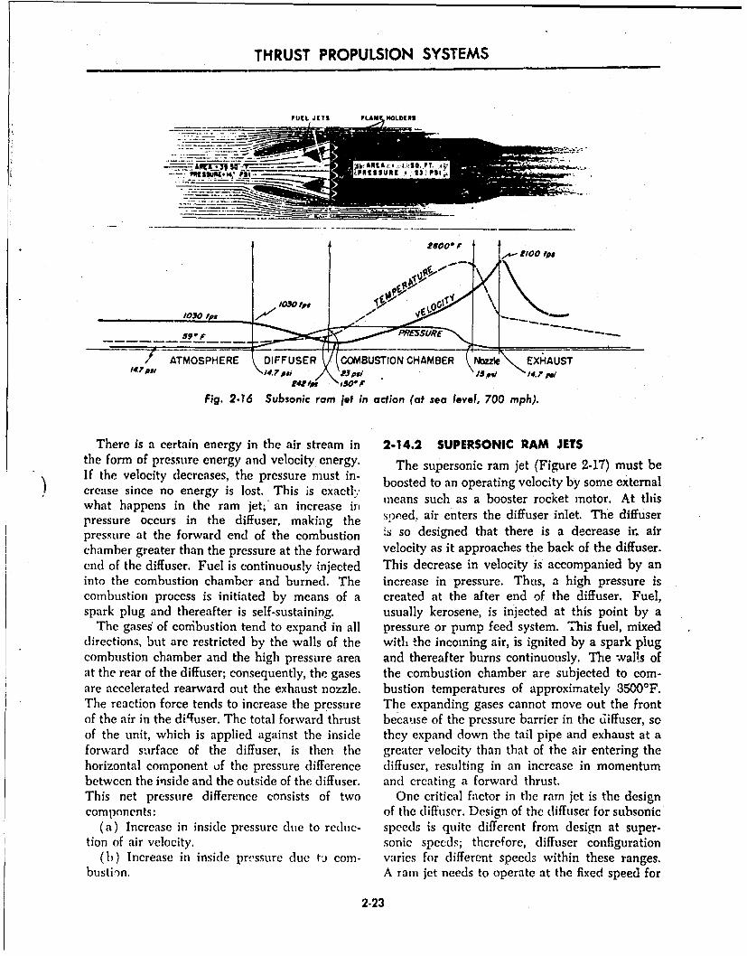
THRUST PROPULSION SYSTEMS
FUEL JETS FLAM HOLDERS
t2000 fo
ATMOSPHERE ý DIFFUSER COMBUSTION CHAMBER N=Ie EXHAUST147~j 4.,pa / 7 ps;\ /5ow 1.77
Fig. 2-76 Subsonic ram jet in action (at sea level, 700 mph).
There is a certain energy in the air stream in 2-14.2 SUPERSONIC RAM JETSthe form of pressure energy and velocity energy. The supersonic ram jet (Figure 2-17) must beIf the velocity decreases, the pressure must in- boosted to an operating velocity by some externalcrease since no energy is lost. This is exactlywhat happens in the ram jet; an increase i means such as a booster rocket motor. At thiswhatd aipen ener the difuse inlet an diffuseerrpressure occurs in the diffuser, making the seeed, air enters the diffuser inlet. The diffuserpressure at the forward end of the combustion s so designed that there is a decrease ir. airchamber greater than the pressure at the forward velocity as it approaches the back of the diffuser.end of the diffuser. Fuel is continuously injected This decrease in velocity is accompanied by aninto the combustion chamber and burned. The increase in pressure. Thus, a high pressure iscombustion process is initiated by means of a created at the after end of the diffuser. Fuel,spark plug and thereafter is self-sustaining, usually kerosene, is injected at this point by a
The gases of conibustion tend to expand in all pressure or pump feed system. This fuel, mixeddirections, but are restricted by the walls of the with the incoming air, is ignited by a spark plugcombustion chamber and the high pressure area and thereafter burns continuously. The walls ofat the rear of the diffuser; consequently, the gases the combustion chamber are subjected to com-are accelerated rearward out the exhaust nozzle. bustion temperatures of approximately 3500'F.The reaction force tends to increase the pressure The expanding gases cannot move out the frontof the air in the diffuser. The total forward thrust because of the pressure barrier in the diffuser, soof the unit, which is applied against the inside they expand down the tail pipe and exhaust at aforward surface of the diffuser, is then the greater velocity than that of the air entering thehorizontal component of the pressure difference diffuser, resulting in an increase in momentumbetween the inside and the outside of the diffuser. and creating a forward thrust.This net pressure difference consists of two One critical factor in the ram jet is the designcomponents: of the diffuser. Design of the diffuser for subsonic
(a) Increase in inside pressure due to reduc- speeds is quite different from design at super-tion of air velocity. sonic speeds; therefore, diffuser configuration
(b) Increase in inside pressure due tb com- varies for different speeds within these ranges.bustiion. A ram jet needs to operate at the fixed speed for
2-23
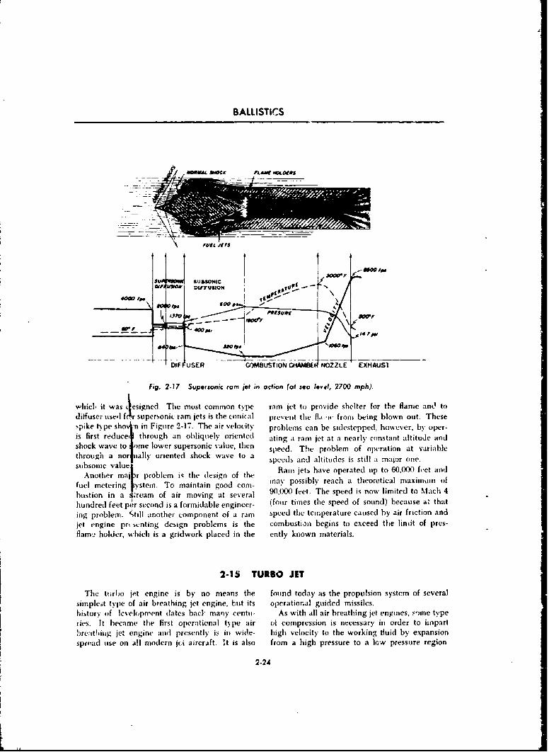
BALLISTICS
-W fo
JiruloN Op
DW USER - COMBUSTIO C~iA~edNOZLs XA~
Fi. -7 upronc a gt nocio otse ~vI6200 mph)
whicbIY~ itws~sge h ot mo n type ram jttopvieslerortefaendo
shock ~ ~ ~ ig 2a17 t melwrSupersonicvlute iga ram jet at ao nearl contan altitud 270ndh)
shc aet m oe sproi aute speed. The problem of operation at variablethrough anor iually oriented shock wave to a scl n liue ssilamjroesubsonic valuepes n liuesi tl amjroe
Anot er a rbe ~te(eino h Rani jets have operated tip to 60.000 feet anti
fuel metering -ystem. To maintain good com- may possibly reach aL theoretical maximnui of
hustion in a t~ream of air moving at several 90,000 feet. The speed is now limited to Mach 4
hundred feet pter second is a formidable engineer- (foiir times the speed of sound) because a, thating problemn. ',till another component of a ram speed the temperature caused by air friction andjet engine pr. mwnting design problems is the combustion begins to exceed the limit of pres-flamu holder, which is a gridwork placed in the ently known materials.
2-15 TURBO JET
The Itirho jet engine is by no means the found today as the Propulsion system of severalsiinple~it type of air breathing jet engine, but its operational guided missiles.history of lcvelopment dates bacl many centim- As with all air breathing jet engines, some typelies. It hecame thme first operational t~pe air or compression is necessary in order to impartbre:tthiiig jet engine and presently is in wide- high velocity to the working tluid by expansionsprvad use on all modern jfA aircraft. it is also from a high pressure to a low. pressure region.
2-24
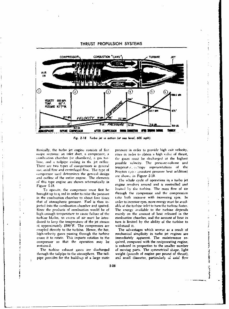
THRUST PROPULSION SYSTEMS
COMPRESSOR COMUSTION "CANS" e TURIUME J
_-_ -. -.,.---.-,-__
Fig. 2-18 Turbo iet n action (at sea level, 600 mph).
Basically, the turbo jet engine consists of five pressure in order to provide high exit velocity,major sections: an inlet duct, a compressor, a since in order to obtain a high value of thrust,cc, mhuistion chamber (or chambers), a gas taar- the gases must be discharged at the highestl~inet, andl a tailpipe ending in tht jet orifice. possible veloity. The prtssure-voluine aridThere are two types of compressors in general temperat',r .-,'ropy representations of theuse, axial flow and centrifugal flow. The type of Brayton C,,cu ke•onstant pressulre heat addition)compressor used determines the gencral designand outline of the entire engine. The elements are show,F in Figure 2-19.
of this type engine are shown schematically in Tewoecceo prtosi ub eFigure 2-18. engine revolves around and is controlled and
To operate, the compressor must first be limited 1,y the turbine. The mass flow of airbrought up to sj eed in order to raise the pressure through the compressor and the compression
'-in the combustion chamber to about four times ratio both increase with increasing rpm. InS that of atmospheric pressure. Fuel is then in- order to increase rpm, more energy must be avail-Sjected into the combustion chamber and ignited. able at the turbine inlet to turn the turbine faster.SSince the products of combustion would be of The energy available to the turbine depends
high enough temperature to cause failure of the mainly on the amount of heat released in theSturbine blades, ain excess of air mu~t be intro- combustion chamber, and the amount of heat inSdoced to keep the temperature of the jet stream turn is limited by the ability of the turbine to -!at approximately 15OO°F. The compressors are withstand it.
- coupled directly to the turbine. Hence, the hot, The advantages which accrue as a result of
Shigh-velocity gases passing through the turbine mechanical simplicity in turbo jet engines are
6474
tcause it to rotate. This imparts rotation to the immediately apparent. The maintenance re-Scompressor so that the operation may be quired, compared with the reciprocating engine,
sustained, is reduced in proportion to the smaller numberhSThe turbine exhaust gases are discharged of moving parts. The symmetrical shape, lightthrough the tailpipe to the atmosphere. The tail- weight (pounds of engine per pound of thrust),
o pipe provides for the build-sp of a large static and small diameter, particularly o axia! flow
Figu2 225 r
To oprttecmrso is is e lmie h ubn.Tems lwo ibrouht p t si ee inordr toraie te pessre hrogh he cmprsso an th copresio
intecmutoIhme oaotfu ie ai ohices ihicesn p.I
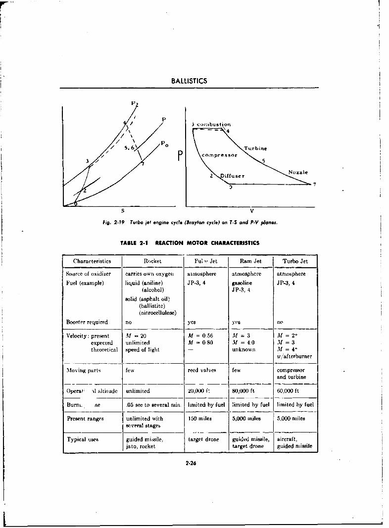
BALLISTICS
P
3 connbustion
N/7
S V
Fig. 2-19 Turbo jet engine cycle (Brayton cycle) on T-S and P-V planes.
TABLE 2-1 REACTION MOTOR CHARACTERISTICS
Characteristics Rocket Pu''"ý Jet Ram Jet Turbo Jet
Source of oxidizer carries own oxygen atmosphere atmosphere atmosphere
Fuel (example) liquid (aniline) JP-3, 4 gasoline JP-3, 4(alcohol) JP-3, 4
solid (asphalt oil)(ballistite)(nitrocellulose)
Booster required no yes yes no
Velocity: present Al = 20 AM = 0.56 31 = 3 M = 2+expected unlimited M = 0.80 M = 4.0 If = 3theoretical speed of light - unknown M = 4+
w /afterburner
Moving parts few reed valves few compressorand turbine
Operat: d altitude unlimited 20,000 f: 80,000 ft 60,000 ft
Bur ro. ne .05 sec to several min. limited by fuel limited by fuel limited by fuel
Present ranges unlimited with 150 miles 5,000 miles 5,000 milesseveral stages
Typical user guided missile, target drone guided missile, aircraft,jato, rocket target drone guided missile
2-26
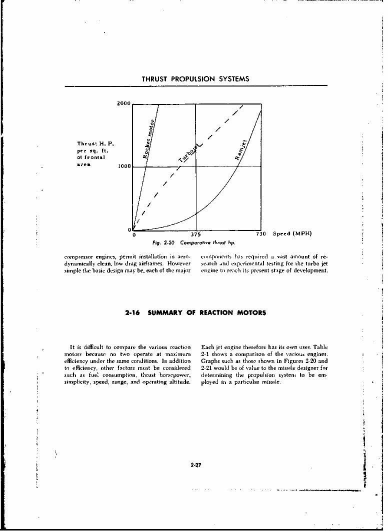
THRUST PROPULSION SYSTEMS
ZOO0 /
//0
Thrust H. P.per sq. ft. 0
at frontal
1000
/iAL.* e41 0
0 0 375 730 Speed (MPH)
Fig. 2-20 Comparative thrust hp.
compressor engines, permit installation in aero- components has required a vast amount of re-dynamically clean, low drag airframes. However .search and experimental testing for the turbo jetsimple the basic design may be, each of the major engine to reach its present stage of development.
2-16 SUMMARY OF REACTION MOTORS
It is difficult to compare the various reaction Each jet engine therefore has its own uses. Table
motors because no two operate at maximum 2-1 shows a comparison of the various engines.efficiency under the same conditions. In addition Graphs such as those shown in Figures 2-20 andto efficiency, other factors must be considered 2-21 would be of value to the missile designer for
such as fue' consumption, thrust horsepower, determining the propulsion system to be em-
simplicity, speed, range, and operating altitude, ployed in a particular missile.
2-27-------------------------------------- ___r~~
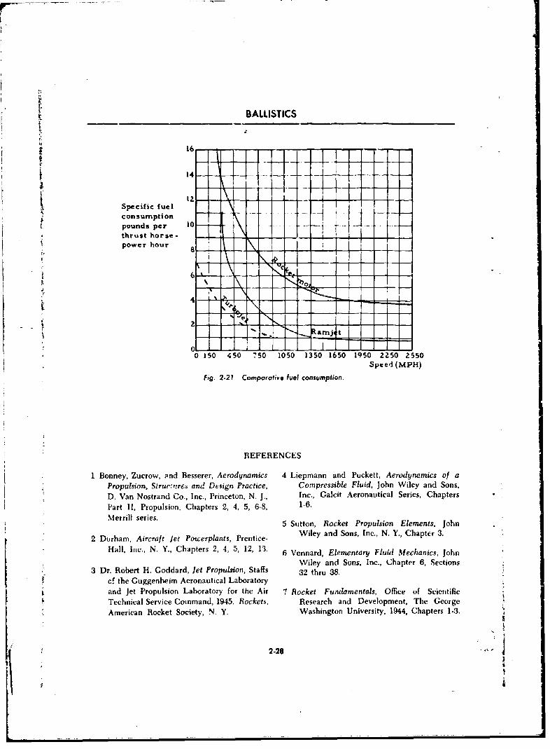
BALLISTICS
4
pondpe 0 - - -
0 150 450 750 1050 1350 1650 1950 2250 2550
Speed (MPH)
Fig. 2.21 Comporotive fuel consumption.
REFERENCES
I Bonney, Zucrow, ?nd Besserer, Aerodynamics 4 Liepmann and Puckett, Aerodynamics of aPropulsion, Slrucrtrey and Design Practice, Compressible Fluid, John Wiley and Sons,D. Van Nostrand Co., Inc., Princeton, N. J., Inc., Galcit Aeronautical Series, ChaptersPart I1, Propulsion, Chapters 2, 4, 5, 6-8, 1-6.Merrill series. 5 Sutton, Rocket Propulsion Elements, John
2 Durham, Aircraft jet Powerplants, Prentice- Wiley and Sons, Inc., N. Y., ChaptCr 3.
Hall, Inc., N. Y., Chapters 2, 4, 5, 12, 13. 6 Venrard, Elementary Fluid Mechanics, John
Wiley and Sons, Inc., Chapter 6, Sections3 Dr. Robert H. Goddard, let Propulsion, Staffs 32 thru 38.
cf the Guggenheim Aeronautical Laboratoryand jet Propulsion Laboratory for the Air 7 Rocket Fundamentals, Office of Scientific
Technical Service Command, 1945. Rockets, Research and Development, The George
American Rocket Society, N. Y. Washington University. 1944, Chapters 1-.3.
2-28
LI
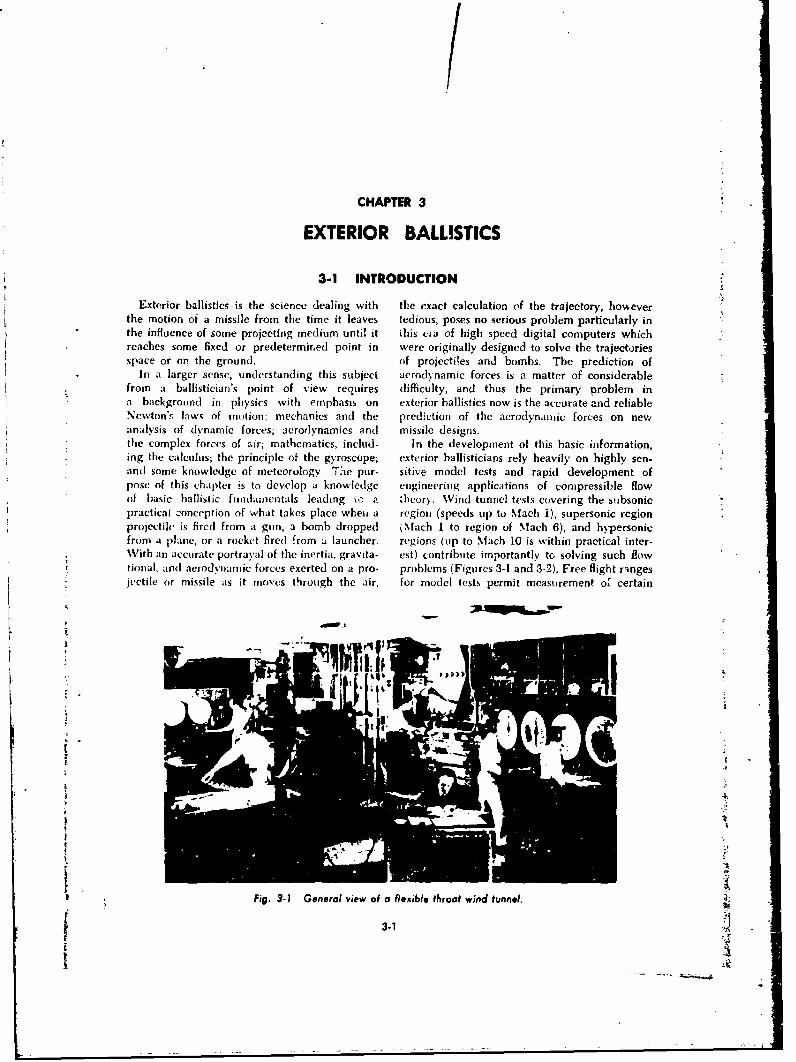
/CHAPTER 3
EXTERIOR BALLISTICS
3-1 INTRODUCTION
Exterior ballistics is the science dealing with the exact calculation of the trajectory, howeverthe motion of a missile from the time it leaves tedious, poses no serious problem particularly inthe influence of some projecting medium until it this eia of high speed digital computers whichreaches some fixed or predetermined point in were originally designed to solve the trajectoriesspace or on the ground. of projectites and bombs. The prediction of
In a larger sense, understanding this subject aerodynamic forces is a matter of considerablefrom a ballistician's point of view requires difficulty, and thus the primary problem ina background in physics with emphasis on exterior ballistics now is the accurate and reliableNewton'.s laws of motion; mechanics and the prediction of the aerodynamic forces on newanalysis of dynamic forces; aerodynamics and missile designs.the complex forces of air; mathematics, includ- In the development of this basic information,ing the calculus; the principle of the gyroscope; exterior ballisticians rely heavily on highly sen-and some knowledge of meteorology. T.-e pur- sitive model tests and rapid development ofpose of this chapter is to develop a knowledge engineering applications of compressible flowof basic ballistic fundamentals leading a z theory. Wind tunnel tests covering the subsonicpractical conception of what takes place when a region (speeds up to Mach 1), supersonic regionprojectile is fired from a gun, a bomb dropped kNfach 1 to region of Mach 6), and hypersonicfrom a plane, or a rocket fired .rom a launcher. regions (up to Mach 10 is within practical inter-With an accurate portrayal of the inertia, gravita- est) contribute importantly tG solving such flowtional, and aciodynamic forces exerted on a pro- problems (Figures 3-1 and 3-2). Free flight rangesjectile or missile as it moves through the air, for model tests permit measurement of certain
•,No .,
k[ fAA
| .,
Fig. 3-1 General view of a flexible throat wind tunnel.
3.1Ik'
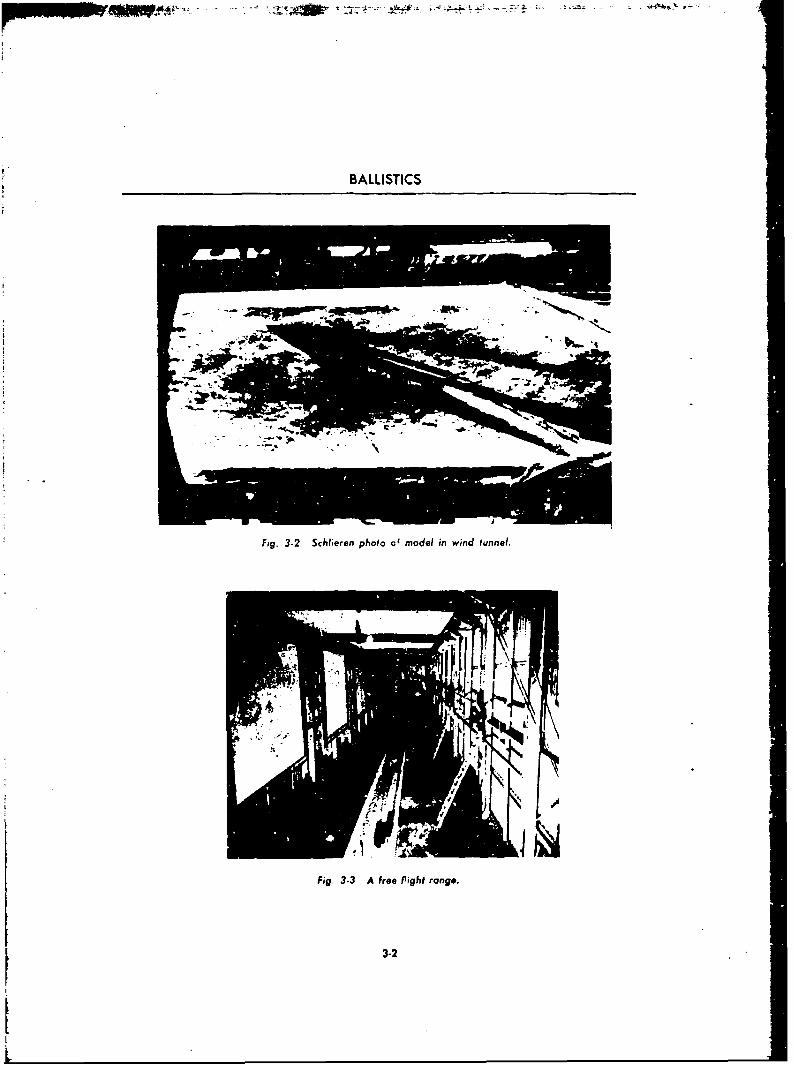
BALLISTICS
Fig. 3-2 Schlieren photo of model in wind tunnel.
Fig. 3.3 A free Pight range..
1 3-2
t
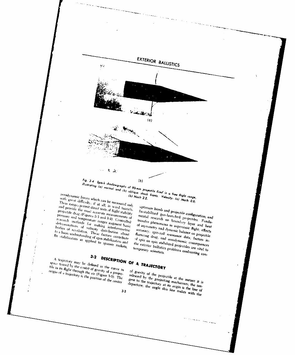
EXTERIOR 83ALLISrgCS
F'-34 SP0 k shod0.(b
an) toro, l9'o h g, In(,) s. hock r*9
I dVrh dy0 e wAhi cahb i(b oi 2.2. £ Yj, 1 () ronge,
at t1 lif,:Ica
b e a ue Of0y , Mach 0.8;
boa,,c ofn ofi Velct , ifatal e as,, c 0,1,
to a i* '0111t 'c' tests iut
amif balnc 11gh ef
i***'i(Ie aThC rt lta ilt. f"s b id Projectilel
pr-sfr 9 o(Fiaute s rn'sr ne t M t al an gu n-at nehe data ti n
an Qnc.,, n 34.g'nrn, jol C he f~t
problem pro jecle s ' da
dv(,n atifO, S fur J~ gs taiinent rib lt SPin gne, fa ctor s an h a
11 ton oc t o 5 Pi nnr h ak
tan iizd 7dCyne ue c
CO~~~Via toc,. Mi aac
finflrtan r ed st c.o
E~ F ftg~ fo sp in
iligbi r ib e "hnc '
traced
-spi 'h spit)~ ofa
-] a nni
consci
toi,, ofn
" ') Taugh the
xtir, rg r
I 'Zdc Projectile ofuryi
f hr Thcet, trelese b th Projecisi st theVta
traedIha e defi tine ente"ri V OF arur
a its nESm .,e arPant itt
make wih h
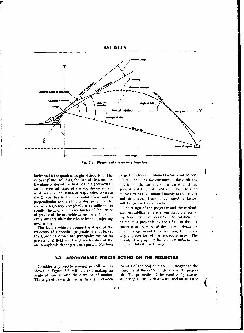
BALLISTICS
y
,i-d am
0tI
L. -- ,. -
Fig. 3.5 Elvments of th* artillery traecdory.
horizontal is the quadrant angle of departure. The range trajectories additional factors must he con-vertical plane including the line of departure is sidered, including the curvature of the earth, thethe plane of departure. In it lie the X (horizontal) rotation of the earth, and the ,arijation of th.and Y (vertical) axes of the coordinate system gravitational fi, ld with altitude. The discussionused in0 the computation of trajectories, whereas in this text will be confined mainly to the gravitythe Z axis lies in the horizontal plane and is and air effects. Long range trajectory factorsperpendicular to the plane of departure. To de- will be covered verv briefly.scribe a trajectctr completel it is sufficient to The design of the projecile and the methodsspecify the x, y, and z coordinates of the center used to stabilize it have a considerable effect onof gravity of the projectile at any time, t (i.e.. atevery instant), after the release by the projecting the trajectory. For example, the rotation ins-
mechanism, parted to a projectile by the rifling in the gut
The factors which influence the shape of the causes it to move out of the plane of departure
trajectory of a specified projectile after it leaves due to a crosswind force resulting from gyro-the launching device are principally the earth's scopi,_ precession of the projectile nose: Thegravitational field and the characteristics of the density of a projectile has a direct influence on
air through which the projectile passes- For long both its stability and range
3-3 AERODYNAMIC FORCES ACTING ON THE PROJECTILE
Consider a projectile moving in still air, as the axis of the projectile and the tangent to the
shown in Figure 3-6, with its axis making an trajectory at the center of gravity of the projec-angle of yaw i, with the direction of motion ie. The projectielle w r he acted on by gravitThe angle of yaw is defined as the angdc between m, acting veptically downward, and an air forcea
3-4
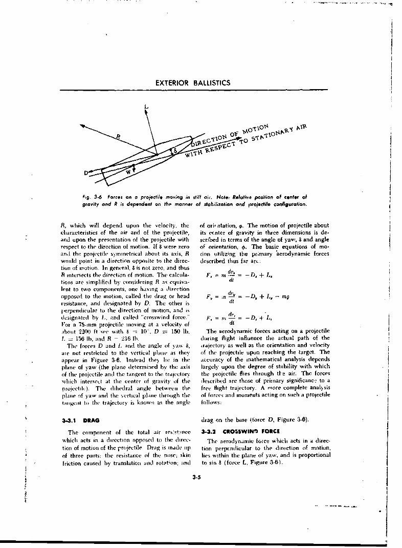
EXTERIOR BALLISTICS
Fig. 3-6 Forces on a projectile moving in still air. Note: Reloiivo, position of canter of
gravity and R is dependent on the manner of stabilization and projectile configuration.
R, which will depend upon the velocity, the of oriffltation, ,. The motion of projectile aboutcharacteristics of the air and of the projectile, its crnter of gravity in three dimensions is de-and upon the presentation of the projectile with scribed in terms of the angle of yaw, 8 and anglerespect to the direction of motion. If 6 were zero of orientation, 0. The basic equations of mo-
and the projectile symmetrical about its axis, R don utilizing the pr.mary aerodynamic forceswould point in a direction opposite to the direc- described thus far arc:
tiun of motion. In general, S is not zero, and thusR intersects the direction of motion. The calcula- F. = m . D, + L.lions are simplified by considering R as equiva- dl
lent to two components, one having a oirection dtl
opposed to the motion, called the drag or head F, ' D= -D. + L. - mgresistance, and designated by D. The other is dt
perpendicular to the direction of motion, and isdesignated by I, and called "crosswind force." F, = mi d-- = -D, + L,F~or a 75-mm projectile moving at a velocity of dt
.bout 2200 ft wee with 8 10= , D = 150 lb. The aerodynamic forces acting on a projectile
1. 156 lb. and R - 216 lb. during flight influence the actual path of the
The forces D and I. and the angle of yaw 8, trajectory as well as the orientation and velocityare not restricted to the vertical plane as they of the projectile upon reaching the target. Theappear in Figure 3-6. Instead the> he in the accuracy of the mathematical analysis depends
plane of yaw (the plane determined by the axis largely upon the degree of stability with whichof the projectile and the tangent to the trajectory the projectile flies through tfe air. The forces
which intersect at the center of gravity of the described are those of primary significance to aprojectile). The dihedral angle between the free Nlight trajectory. A mnore complete analysisplane of yaw and the vertical plane through the of forces and moments acting on such a projectile
tangcot to the trajectory is knowi as the angle follows:
3-3.1 DRAG drag on the base (torce 0, Figure 3-6).
The compnnent of the total air resst-,nce 3-3.2 CROSSWINn FORCE
which acts in a direction opposed to the direc- The aerodynamic force which acts in a direc-
tion of motion of the Pr(,jectile. Drag is made tip tion perpenldicular to the direction of motion,
of three parts: the resistance of the nose; skin lies within the plane of yaw, and is proportional
friction caused by translation and rotation; and to sin 8 (force L, Figure 3-6).
3-5
a-
I
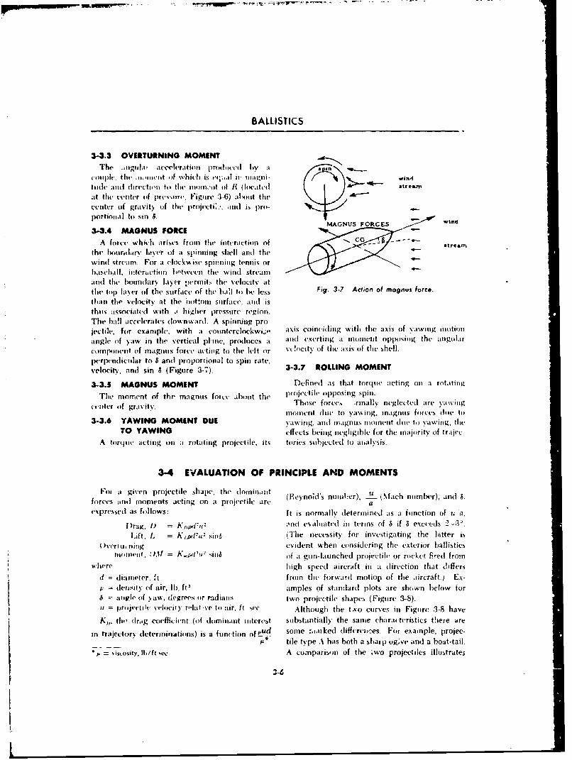
T M-I r* ,&. --5 -
BALLISTICS
3-3.3 OVERTURNING MOMENTThe inglivoIa a("Iera tio n produiced by ataI
couinple, the c. .in cilt .4 which is c'c; iIa u-' 1cagni- wind
111(14 and( cirvctii'i to the iloifl"ait of R~ (locaited &streamn
at the center of pressure, Figuire :3-6) abiout the
centetr of gravity of the projl'cti: ', adu~ is pro-
prin tsiS.MAGNUS FORCES wind
3-3.4 MAGNUS FORCEA force which arises froin the initeraction of Gsra
the' Ixicir~tary laser of it spinnring shlf and thewind stream For a clockwise spinning tennis orbaseball, interictitin between the wind stream.10(1 fik bohindarý layer perinit, the velocity attthme to1) taxer of thie surface of thi' bll to be- k..s Fig. 3-7 Adcin of magnus force.than) (lhe velocity at the bottom surface, anud isbthus associated with ;i higher piressure region.The hdlI accelerates (lovw.ward. A spinning pro-jectile, for example, with at (ounnierclock-wi~.' axis coinlcidhing withi the axis of %iawing inotionangle oif yaw in the vertical pl~ine, produces aI amnd exerting at inonient oIppoin~fg the amngular
comipmeneit (if magnus force acting to the lefti or vtlocity of the axis of thme shell.pi'rjwtnd icualar to 8 and proportionial to spin rate, 337 RLIGMMNvelocit-, and sin 8 (Figure 3-7).3.7 OLIGM EN
3-3.5 MAGNUS MOMENT Defined as that torque acting on a rotatimim,
The mnoment of the magnims force albnut the projectile- op)posing spin.
(I-lter oif gramvitv Those force, rinally neglected arte yawingmnomoent (lice to ya%%ing, inagnils forces doe toi
3-3.6 YAWING MOMENT DUE %awing. amnd uhignus mioment duet( to yawing, theTO YAWING effects being negligible for the majority of Irikjec-
A torqjue ac ting on a rotating projectile, its tories subjected to ainalysis.
3-4 EV'ALUATION OF PRINCIPLE AND MOMENTS
For it given projectile shape, the dIomfinanit (Reynoid's nuund tr), _" (Mach number.), and S.forces and moments acting on a projectile are aexpresse-d as follows: It is normally dletermined as it function of u a,
D~rag, 1) A npVic' rnd evaluiated in terms of S if S exceedls 2-3'.
laift, L. = A1.pd~u' siii& (The necessity for investigating the latter iskert, oiingevident when considering the exterior ballistics
iiiifiieit )1! =K~p4u' saiSof a gun-latmnched projectile or rocket fired fromw here high speed aircraft in a direction that differs
d = ijianwiuer. ft fromn the forwaril motiop of the aircraft.) Ex-p= denc~ify (if air, lb ,ft 3 amples of standard plots are shown below for
6 = aug'ecof ' %aw, degreos ior radians two projectile shapes (Figure 3-8).11=projecile I velocity ri-lative to air, ft see Although the tAsU curves iii Figure .3-8 have
X". thne dlrag coefficim-nt (of dominant interest substantially the sariie characteristics there are
in trajectorN determincations) is a function of 0d some rncamked differen~ces, For example, projec-,s tile type A has both a sharp og've and a boat-tail.
= '..~osiiy' li/ft 'cc A comparisonl of the ýwo projectiles illustrates
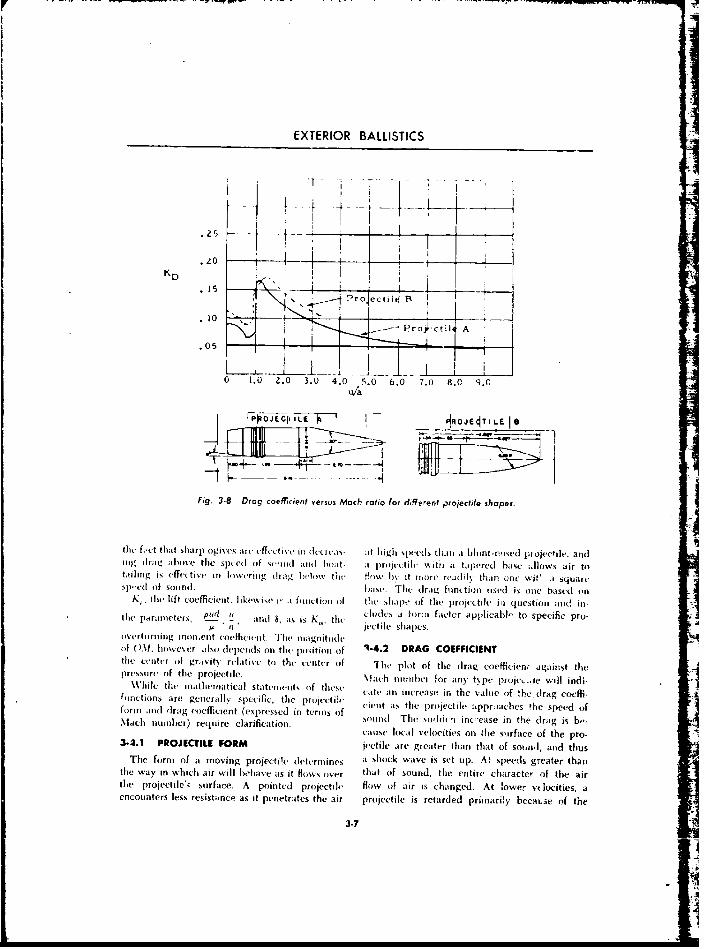
EXTERIOR BALLISTICS
Prot croec B I
10Pro~cr
.05-
0 1.0 2.0 3.0 4.0 5.0 6.0 7.0 8.C Q. 054/
1_PP-iEe"_- I`0F E 5IO T I L E 8s
Fig. 3-8 Drag coefficient versus Mach ratio for different projectile shapes.
the f..ct tha~t slarp ogivcs s rc c fs 5 t i% v it) dc crva ax t h igh spees than ti in int -nosed pi ojecti le. adnig dlrat, alo.ts p clsfx nt is oa pr p s lihi %%tii a t apered base .Ilcws air ttasilinrg is effvctiv ini (m riu, sdr s,. 1 xx tiri How bN it ino ri r .i1 l than uric wit' i squalNlwed ofi sounrd. base.i TIe dr ag futis n ti s ied is one based o
K, tie lift coa ffica iet s lkc ise i', -1 f~~i~ I t Ossf the shp ol jc(f the projec tile mi question andin-[lie paramreters, ip51! it ,an 8 its is K_ the cideuss a for i f sctcr apiplicabl- to specific pto
vertnrii AA m "i~ei C5)cficaiit shapesi.ita
of ().W. hiowevcer also sdependis onl the poisitiuun of ~2 DA OFIINthe cseiter Ofi gravity relaitive tos the Center (of The plot of the dirag coeffciefl, againist tliepressiirv of the projectile. M~ach niiriiei for any' tipe proje5 te will indi-While I the mat hem atical statemients sif these sits an increase in, the value of 'he druag coeff-A(;inctions are generall 'y specific, the prisiectiv i rs ta h rjcieaprabstesedofusrin .ancd drag cuoefficient (expressed in teriis aof siend axthe sudri~niiecle appoesi the sedra is f
Machnumer) equre cariicaton.cause local velocities on Zhe suirface of the pro-A3.4.1 PROJECTILE FORM jactile are greater than that of sound, aiid thus
The form nf a moving projectile sdetermiines aishok wvave is set tip). At speeds greater thanthe way in which air will bhelave as it Hiuws Over that of sound. the entiie character of the airthe projectile', surface. A pouinted projectile flow of afir is changed. At lower- vtlocities, aencounters less resistance as it penetrates the air projectile is retarded primarily becasse of the
:3-7
[
P
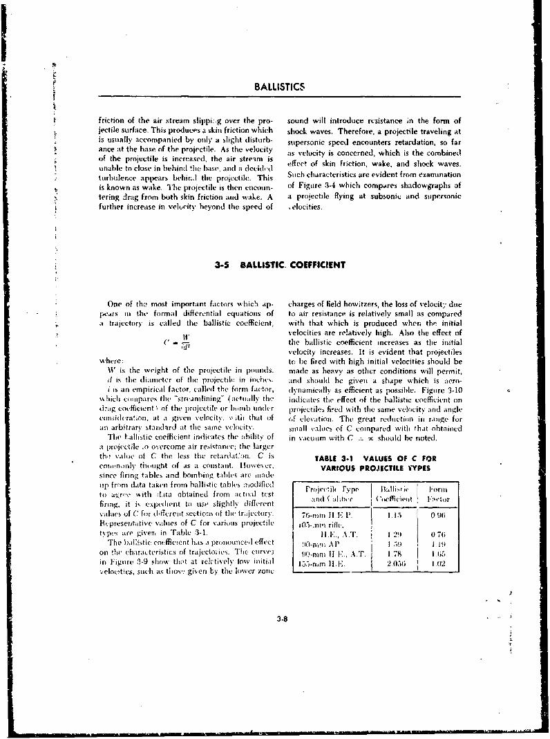
S~ BALLISTICS
friction of the air stream slippi: g over the pro- sound will introduce resistance in the form ofSjectile surface. This produces a skinl friction which shock waves. Therefore, a projectile traveling at
is usually accompanied by only' a slight disturb- supersonic speed encounters retardation, so farS~~~ance at the base of the projectile. As the velocity svoiiscneedwhhisheomneavelocity is the which is the combinedeffect of skin friction, wake, and shock waves.•. unable to close in behind !hle base, and a decidhed
turbulence appears behir..l the projectile. Thi Such characteristics are evident from examinationis known as wake. The projectile is then encoun- of Figure 3-4 which compares shadowgraphs oftering drag from both skin friction and wake. A a proiectile flying at subsonic and supersonicfurther increase in velocity beyond the speed of .elocities.
3-5 BALLISTIC. COEFFICIENT
* One of the most important factors which ap. charges of field howitzers, the loss of velocity due
"* pears in the formal differential equations of to air resistance is relatively small as compared
a, trajectory is called the ballistic coefficient, with that which is produced wher. the initialvelocities are re!atively high. Also the effect of
" the ballistic coefficient increases as the initial
-here: ivelocity increases. It is evident that projectilesSwhere: to be fired with high initial velocities should be
It' is the weight of the projectile in pounds. made as heavy as other conditions will permit,d is the diameter of the projectile in inches. and should he given a shape which is aero-i is an empirical factor, called the form factor, (lynamically as efficient as possible. Figure 3-10
which colmpares tihe "strcamlining" (actually the indicates the effect of the ballistic coefficient ond.'ag coefficient I of the projectile or bmb undcr projectiles fired with the same velocity and angleconsihderalion, at a given velocity, with that o[f cJ clevation. The great reduction in range foran arbitrary standard at the same velocity. small values of C compared with that obtained
The -allistic coefficient indicates the ability of in vacuum with C =- x shoold be noted.a projectile .o overcome air resistance; the largerth, value of C the less the retardat:n. C is TABLE 3-1 VALUES OF C FORcowinooly thotught of as a constant. However, VARIOUS PROJECTILE YYPESsince firing tables and bombing tahblv are madeup from data taken from ballistic tables modified -rojec~ih- Fypv Ballistic I-or-to at'rre with l.ita obtained from acitual test I Ifiring, it is expedient to use slightly different and ( alhbr (Coefficient *':ltlor
values of C for different sections of the tritjectory. 7ti-nim II E P. 1 15 0 96
Rt presentative vi:lues of C for various projectile i05-.nm rifle,types are giver, in Table 3-1. Il.l, A T_ i 12 0 76
The ballistic coefficient has a pronounced, effect 90-mmqi AP I .- i 1.19on tic charaicteristics of trajectories. Thc ciirve3 90-nini If V., A.T. I 78 I 115in Figure 3-9 show that at reh:tively low initial 135-rim II. 2.05(; 1 wIvelocities, such as thos,: given by the lower zone
3.8
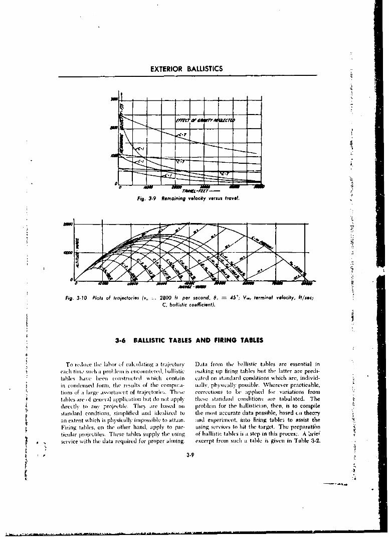
EXTERIOR BALLISTICS
fin r ff 4"amj
7
To rduc thelabr ofc lFing. a- tReainctor veocty feroms trae bl.si alsaeesnili
tFig. 3-1 Plotg ,sMrIt of trajectoriesY, .20 ftb per scorrcnd, to 45 appleriedalo varoiation from~
Tole aredofe ghelabrl ofppliclatin au dontrappltoy Dthea frmthnar onditiontble are tabulnted. The
eahtiin.l ý which apro~etl.c Ties crcrohlcbalitc aing i firin thebales tci, tholter, is e ompie
inc odnsdtfons, tbirepltse and ide pl'ized to l% the m st accraeat possible , basreed practicbe,tionsof ala is physically inopussibletorv. aThain cnd epeimenst, int firingfo variaetionasst them
Firing tables, on the other hand, apply to par- using services to hit the target. Thu preparatibn
ticular pnUVcctiles. These tables supply the using of ballistic tables is at step in this provces-. A briiefservice with the data required for proper aiming, excerpt from such atable is given in Tahle .3-2.
t 3-9
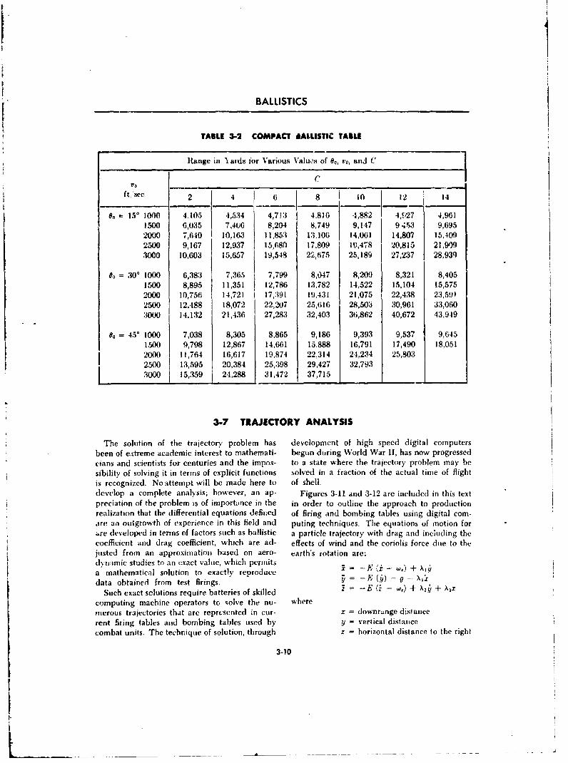
4BALLISTICS
I1
TABLE 3-2 COMPACT LALLISTIC TABLE
lHange in I ards for Various Vaiu,ýs of e0, va, and C
CVO
ft2se4 6 8 10 12 14
an= 15 low 4,105 4,534 4,713 4.8)6 -1,882 4,ý',27 4,961
1500 6,035 7,406 8,204 8,749 9,147 9 453 9,6952000 7,640 10,163 11,853 13,106 14,061 14,807 15,4092500 9,167 12,937 15,680 17,809 10,478 20,815 21,909.3000 10,603 15,657 19,548 22,675 25,189 27,237 28,939
0= 30° 1000 6,383 7,365 7,799 8,047 8,209 8,321 8,4051500 8,895 11,351 12,786 13,782 14,522 15,104 15,5752000 10,756 14,721 1 17,391 19,431 21,075 22,438 23,5912500 12,488 18,072 22,207 25,616 28,503 30,961 33,0603000 14,132 21,436 27,283 32,403 36,862 40,672 43,949
o= 450 1000 7,038 8,305 8,865 9,186 9,393 9,537 9,6451500 9,798 12,867 14,661 15,888 16,791 17,490 18,0512000 11,764 16,617 19,874 22,314 24,234 25,8032500 13,595 20,384 25,398 29,427 32,7933000 15,359 1 24,288 31,472 37,715
3-7 TRAJECTORY ANALYSIS
The solution of the trajectory problem has development of high speed digital computersbeen of eý.treme academic interest to mathemati- begun during World War II, has now progressedcians and scientists for centuries and the impos- to a state where the trajectory problem may besibility of solving it in terms of explicit functions solved in a fraction of the actual time of flightis recognized. No attempt will be made here to of shell.develop a complete analysis; however, an ap- Figures 3-11 and 3-12 are included in this textpreciation of the problem is of importance in the in order to outline the approach to productionrealization that the differential equations defined of firing and bombing tables using digital com-are an outgrowth of experience in this field and puting techniques. The equations of motion for"are developed in terms of factors such as ballistic a particle trajectory with drag and inciuding thecoefficient and drag coefficient, which are ad- effects of wind and the coriolis force due to thejusted from an approximation based on aero- earth's rotation are:dvyrtmic studies to an exact value, which permitsa mathematical solution to exactly reproduce . = -E (. - w,)+ ,data obtained from test firings. - E
Such exact solutions require batteries of skilled z = -E (Z - ,) + X•a + X2Z
computing machine operators to solve the nu- wheremerous trajectories that arc represented in cur- x = downrange disiancerent firing tables and bombing tables used by y = vertical distancecombat units. The techrique of solution, through z = horizontal distance to the right
3-10
rII-I
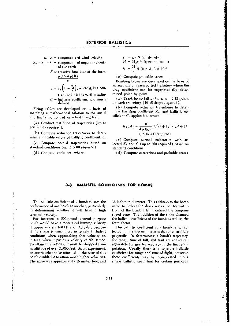
EXTERIOR BALLISTICS
wa., w, = components of wind velocity p = poe-AY (air dpnsity)
X,- M, -1,1 = components of angular velocity M = Mof~e-Ay (speed of sounid)of the earth 2
h = A (h- =3.16 x 10-)E = resistive functions of the form, 2
p (y) uKD(M) (e) Compute probable errorsC Bombing tables are developed on the basis of
/ =w i an accurately measured test trajectory where theg--o I- , where g is a con- drag coefficient can be experimentally deter.
stant and r is the earth's radius mined point by point:
C = ballistic coefficient, previously (a) Track bomb fall .,, me. . ! 6-12 points
defined on each trajectory (10-15 drops required).
Firing tables are developed on a basis of (b) Compute reduction trajectories to deter-
matching a mathematical solution to the initial mine the drag coefficient K, and ballistic co-
and final conditions of an actual firing test: efficient C, applicable, where
(a) Conduct test firing of trajectories (tip to M150 firings required). KD(1) = Vd2 + (j/4 ./g)+ +p• d2p (y/)02
(b) Compute reduction trajectories to deter- (up to 400 required).mine applicable values of ballistic coefficient, C. (c) Compute normal trajectories with se-
(c) Compute normal trajectories based on lected K,, and C (up to 600 required) based onstandard conditions (up to 3000 required). standard conditions.
(d) Compute variations, where (d) Compute corrections and probable errors.
3-8 BALLISTIC COEFFICIENTS FOR BOMBS
Th, ballistic coefficient of a bomb relates the P2i inches in diameter. This addition to the bombperformance of one bomb to another, particularly acted zo deflect the shock waves that formed inin determining whether it will have a high front of the bomb after it cntered the transonicterminal velocity, speed zone. The addition of the spike changed
For instance, a 500-pound general purpose the ballistic coefficient of the bomb as well as thebomb would have a theoretical limiting velocity form factor.of approximately 1000 ft/sec. Actually, because The ballistic coefficient of a bomb is not sc-of its shape it encounters extremely turbulent lected in the same manner as is that of an artilleryconditions when approaching that velocity or, projectile. In determining a bomb's trajectory,in fact, when it passes a velocity of 800 ft''sec. the range, time of fall, and trail are consideredTo attain this velocity, it must be dropped from separately for greater accuracy in the final com-an altitude of over 20,000 feet. As an experiment, putation. Usually there is a separate ballistican antiricochet spike attached to the nose of this coefficient for range and time of flight; however,bomb enabled it to attain much higher velocities. these coefficients may be incorporated into aThe spike was approximately 15 inches long and single ballistic coeffi"ient for certain purposcs.
3.11
BALLISTICS
414 ji
3-121
EXTERIOR BALLISTICS
lei-
Q~.2I .b
4m ol
-3-13
o 4:
£ 0
BALLISTICS
The maximum velocity which any given freely Lim;ting Velocity Ballisticfalling body will attain is called the limiting (ft sec) Coeffiuientvelocity, where retardation due to the air resist- 500 0.33ance is just sufficient to balance the acceleration 1000 2.12due to gravity. Limiting ve!ocity should not be 1500 9.28confused with striking velocity. Since the limit- 2000 15.88ing velocity for bombs may exceed maximumspeed of any plane, the striking velocity can The value of the ballistic coefficient for thenever exceed the limiting velocity unless soremeans such as rocket propulsion is used to in-
crease the velocity of the bomb. The following that the limiting velocity is only about 600-700
table shows the relation between limiting velocity ft/sec. For a heavy armor piercing bomb, aand the ballistic coefficient, higher ballistic coefficient, 5, is desired.
3-9 TYPICAL BOMBING PROBLEMWhen an aircraft, guided on an even forward bomb will meet resistance from the air and will
flight roughly parallel to the surface of the earth, receive resistance or asristance from the vinds,drops a bomb, the following occurs: The bomb depending on their direction. A typical bomb-will have the same initial forward speed as the ing problem as indicated by Figure 3-13 isaircraft but will have no vertical speed; the established.
A C.
I',
CBomb trajectory
Dl
A Pcinlt of releaseB Po nt of -npact (targeg)C Pomition of plant (at time of impact)
Drift angleAC Path of plane (track)AD AltitudeAC Course
BE Cross trail distanceBF Trail distanceDE Actual rangeDY Whole range (track)
Fig. 3-13 Typical bombing problem.
3.14
EXTERIOR BALLISTICSJ
1-9.1 VERTICAL TRAVEL angiui. As titi bomb's) (l'invrardl velocity in-
lDras% n to the earth throuigh gravitational at- ~e~s ~erssac ecs;phirae rstracicii, he ombfals wth n icre-n~ sped. slrc ,ndl force t~he amxis of the bomb io point more
Trisacceleration 1)0mb tollsw ith a inerctard~ s(e~l.b andI more toward ~ii earth. A's it approachesThis~ ~ ~ ~ ~ ~ ~ ~~~~~h aceevto ll ogaiyi eaddlx 1 arth, thli !,ori h deceleraite,; rapi dly on its
t'me increasing density of the air as the lab ininrpahnears thet earth and~ its velocity increases. The lna ah
velocitv of the bomb increaSeS'as it falls, earth- 3-9.3 TRAILwvard, hbut the accelera~tion dvereases with each When a bomb) strikes thec grouind or tarjet. itsecond of travel unttil there is ino acceleration and wil hi~ lagged a cunsiderable (Ii st.nec behinhdthe boinb falls itoa constanit velocity. *T'1is- thet aircraft. This dlistance. knowkn as the trail,ultimate velocity is know~n ats the terininal vvo- Is ain important factor in the eonstruictioin (if
its o the omb oinb~sights. The angle imiade by at line from the
akircraft to the point oif strike. and ai vertical line3-9.2 LINEAR TRAVEL frontm the aircraft to the ground is knovn ats the
The amn reistncefores ffet t~c orwrd, trail angle. Trail is usually expressed in bomb-
or linear, niooyt'iit't of the bombh. v iiuects the igthkasherioresist a ct- causdi b t destyo th air an( ri ml' trail di.,taiie (ft
mtay be pushed or ret arded by 'wind forces, (de- ahlit tide it hi iisani d. of ft
pending ion their direction of travel. If the bomb For example. given it trail distane of 1000 ft andcould lie observed -hrosighout its Rlighit. it tvould anl altitude of 25.000 ft, the trail is 40 milN.he seen to retain at horizontal position parallel tothe airplane for a portion of the flight and then 3-9.4 CROSS TRAILto nose over gradually as. it falls away. Due lo As an aircraft moves along its course, it maygravitational acceleration, the angle between. the encounter lateral wvinds. In order to bring thelongitudinal axis of the boimb and the axis of the atircraft over the target, it mnay lie necessary foraircraft becomnes greater, depending tin the time the aircraift to alter its cotirse to compensate forof flight. For present dav bimnbing, it can be !hv effect of the lateral wind. The striongt r thestattt that this angle never decconies at right lateral wind -he greater the cross (rail.
3-10 SPECIALIZED BOMBING TECHNIQUES
* While the normnal biombinig pm obleni is associ- During an approach **on thie dleck,- the pilot;itetl with the high altitude release of the weapon locates at previously selected landmarki and re-from at moving aircraft against at statiotary target, leases control of the plane to an automatic system
*specialized techniquies have been developed to whiCh places tbe plan:- in at sharp climb at amneet particular requirements of both tactical an(] pretletertitined time, releases the bomb, and.strategic missionis. Included are thc skip botmb- causes the aircraft to roll over and reverse course.ing, torpedo deliver%, and circle bombhing tech- Antitipating at blackout of the pilo)t, the systemnniques of WVorld War II. Thun toss bombing remains in control of the aircraft uintil the pilottechniques of the Korean WVar mnet the require- taka's over ( Figure 31-14 )_ Although flight speed
ment for delivery of high explosive and napalm over 550 miph (7-33 ft sec) is hardly di!,- to lowbombs into cave and bunker openings. altitude turbulence, the bomb release pattern is
An adlditional requirement p~laced uipon the analogous to trie trajectory of a mnortar projectile.ballistician has been that of providing safe and Should weather conditions obscure the initialaccurate low altitudle bombing techniques for landmark, the pilot may cross the target and
3.15
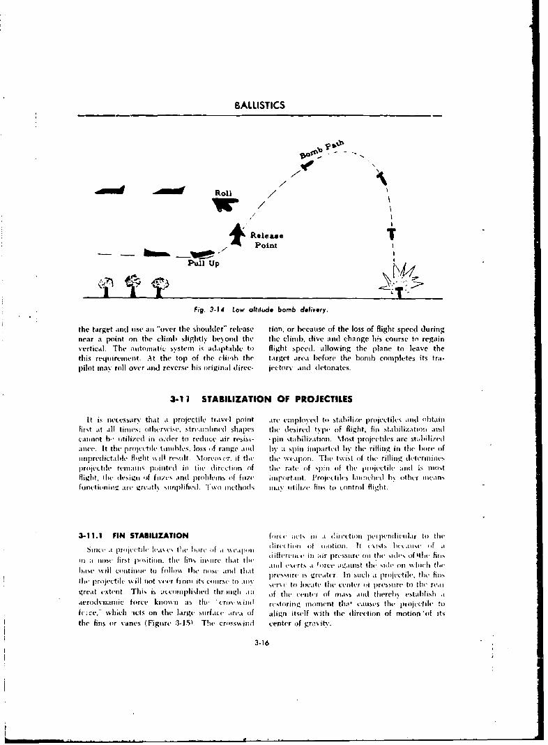
BALLISTICS
Roll /
Release.Iowa 'WWPoint
Piul Up
Fig. 3.14 low allitudi bomb delivery.
the target and itse, .ativ the shoulder" release tion, or bccause of the loss of flight speed duringnear a point on the climb .slightly beyonld the the climb, dive and] chainge h~s course to regainvertical. The automatic systemn is adaptable to flight speed. allowing the plane to leave thethis requirement, At the top of the climib the target area before the bomb completes its tra-pilot may roll over and reverse his oiriginal (lireC- iectorv and (Ietoniatc(.
3-1 1 STABILIZATION OF PROJECTILES
It is necessary that it projectile travel point artr etuplo, cd to stabiliz.e Projectiles and o1)t~ii0first at all times; inthcr-wise. streaniilinvd shapes thne desired tS pm of fli~ght, finl Nt.biliZAt101m Mid
cannot b- uitilized ill o.(le[ to redluce air resis.- 'pinl stabihliztion. Miost projectiles arc sti.bilizedaneec. It the projectile tainimbes. loss of range and by it spint imnpartedl by the rifling, in the horn' ofunpred ict at d flig ht will resutlt. MIorcmcs r. if the tilt xeitponi. TIhe twist of tite riflIing deterin inles
projectile' remains ptioilttc inl the tlircction of thle rate of spin of the projectile andi~ :., mostflight. thIei des ig of ' fin is andI prob leis of fu ze ii inport .init. I roinc~ti les latohi nl 'i bx ot her iileans
fuindwtioio arecrdtI s imIpl ifiedI. T wo methods i isnity Itii/v finls to c-ontrol fl igh t.
3-11.1 FIN STABILIZATION forte ,itts i.1 ti4irect ioti per pcndictilar to thme
sin t.t rocctlc fle or "f'i%% ap ll dirtc tiiiin t i)f otioili It Ic~ats (iti i'i f aa pn~et~l lesesthelio ~fa seaptli diiclietmit-i ill ;,r lresstirc oil the siles oft4114 fills
il aI no0se first positionm the fin% insuire that the Ieet i~ gis h ie t hihtwhame %%ill contiltine to follo%% the foust- andi that Md(\-t oe vis h lvolMc ~l
theproectle vil no vcr hm is curs toill. rcssIre is uravttr. In sn cli at proi ict ile. the~ fill,I m* p jct c wllnotv r i ot ts i in s( o i i ~ sersi (4)t locate thet center oft pressure to thin rear
great cs tent - This is ac ciiompl ishied t hrtingli iii if die cent-nt * of mass anrd t I mere! i es tab lishttelro(ktnamni c force known as t hi e(-rN%\is ssli ri sti inv mit otment thln causes the rijc toiI nf c ce, which -icts on thne large stirface a1rea of align itself with the directiion of motion 'of itsthe fins or vanes (Figure 3-151 The crosswind center of gravity.
3-16
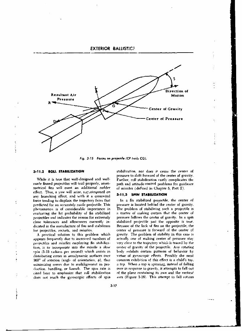
EXTERIOR BALLISVC0
Direction ofResultant Air Motion
Pressure
Center of Gravity
Center of Pressure
Fig. 3-15 Forces on projectile (CP trails CG).
3-11.2 ROLL STAIULIZATION stabilization, nor does it cause the center ofpressure to shift forward of the center of gravity.
While it is true that well-designed and well- Further, roll stabilization vastly complicates the
made finned projectiles will trail properly, asym- path and attitude control problems for guidancemetrical fins will exert an additional rudder of missiles (deFned in Chapter 5, Part 2).effect. Thus, a yaw will arise, sa--rimposed on
any launching effect, and with it a crosswind -11,3 SPIN STABIUZATIONforce tending to displace the trajectory from that In a fin stabilized projectile, the center of
predicted for an accurately nmade projectile. This pressure is located behfnd the center of gravity.
phenomenon is of considerable importance in The problem of stabilizing such a projectile isevaluating the hit probability of fin stabilized a matter of making certain that the center of
projectiles and indicates the reason for extremely pressure follows the center of gravity. In a spin
close tolerances and allowances currently in- stabilized projectile just the opposite is true.dicated in the manufacture of fins and stabilizers Because of the lack of fins on the projectile, the
for projectiles, rockets, and missiles. center of pressure is forward of the center ofA practical solution to this problem which gravity. The problem of stability in this case is
appears frequently due to increa;ed numbers of actually one of making center of pressure stayprojectiles employing fin stabilizR- very clo-e to the trajectory which is traced by the
tion, is to incorporate into the missile a slow center of gravity,-of the projectile. Any rotating
-pin (5-15 radians per second) which assists in body exhibits certain patterns of behavior hydistributing errors in aerodynamic surfaces over virtue of gyroscopic effects. Possibly the most
360' of rotation (angle of orientation. 0), thus common exhibition of this effect is a child's toy.
minimizing errors due to malaligoment in pro- a top. When a top is spinnia.g, instead of falling
,huction, handling, or launch. The spin rate is over in response to gravity, it attempts to fall out
cited here to emphasize that roll stabijization of the plane containing its own and the vertical
does not reach the gyroscopic effects of spin axes (Figure 3-16). This attempt to fall totates
3.17
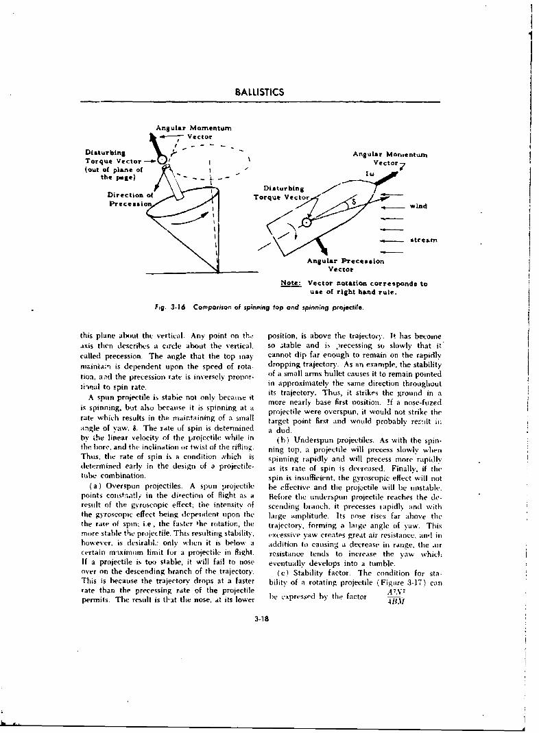
BALLISTICS
Angular Momentuma- Vector
Disturbing , .. - - - Angular Montentu•nTorque Vector -* ' Vector(out of plane of W 7
the page) SW -L-_Disturbing
Direction of Torque VectorPrecessio . ind
Angular PrecessionVector
Note: Vector notation corresponds touse of right hand rule.
Fig. 3-16 Comparison of spinning top and spinning projectile.
this plane about thc vertical. Any point on the position, is above the trajecto-y. It has becomeaxis then describes a circle about the vertical, so stable and is )recessing so slowly that i"called precession. The angle that the top may cannot dip far enough to remain on the rapidlymainiar, is dependent upon the speed of rota- dropping trajectory. As an example, the stabilitytion, aad the precession rate, is inversely pronor- of a small arms bullet causes it to remain pointedtionail to spin rate. in approximately the same direction throughout
A spun projectile is stable not only because it its trajectory. Thus, it strikes the ground in amore nearly base first nositio:. !f a nose-fuzedis spinning, but also because it is spinning at a projectile were overspun, it would not strike the
rate which results in the marintaining of a small target point first and would probably recit iiiangle of yaw, S. The rtte of spin is determined a dud.by the linear velocity of the projectile while in (h) Underspun projectiles. As with the spin-the bore, and the inclination or twist of the rifling. ning top, a projectile will precess slowly whentThus, the rate of spin is a condition .vhich is spinning rapidly and will precess more rapidlydetermined early in the design of a projectile- as its rate of spin is decreased. Finally, if thetube combination, spin is insufficient, the gyroscopic effect will not
(a) Overspun projectiles. A spun projectile he effective and the projectile will be unstable.points const-atl,- in the direction of flight as a Before the underspun projectile reaches the de-result of the gvroscopic effect; the intensity of scending branch, it precesses rapidly and withthe gyroscopic effect being dependent upon the large amplitude. Its nose rises far above thethe rate of spin; i.e, the faster the rotation, the trajector), forming a large angle of yaw. Thismore stable the projectile. This resulting stability. excessive yaw creates great air resistance, anl inhowever, is desirabL only when it is below a addition to causing a decrease in range, the aircertain maximum limit for a projectile in flight. resistance tends to increase the yaw whichIf a projectile is too stable, it will fail to nose eventually develops into a tumble.over on the descending branch of the trajectory, (c) Stability factor. The condition for sta-This is because the trajectory drops at a faster bility of a rotating projectile (Figure 3-17) canrate than the precessing rate of the projectile e4.-y e-permits. The result is that the nose. 0t its lower be expressed by the factor
3-18
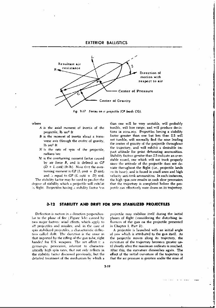
EXTERIOR BALLISTICS
LResult@n i
Direction ofmotion with
respect to air
- Center of Pressure
Center of Gravity
Fig. 3-17 Forces on v projactile (CP leads CG).
where than one will be very unstable, will probablyA is the axial moment of inertia of the tumble, will lose range, and will produce deviz-
projectile, lb sec2 ft tions in accuiacy. Projectiles having a stabilityB is the moment of inertia about a trans- factor greater than one but less than 2.5 will
verse axis through the center of gravity, not tumble, will normally find the nose leading
lb sec2 ft the center of gravity of the projectile throughoutN is the rate of spin of the projectile, the tajectory, and will exhibit a desirable im-radians/sec pact attitude for point detonating ammunition.
Stabiliey factors greater than 2.5 indicate an over-X1 is the overturning moment factor caused stable round, one which will not track properly
by air force R, and is defined as GP since the attitude of the projectile does not de-(D + L cotS) (ft-lb). Note thnt the over- viate throughout the flight (i.e., projectile landsturning moment is GP (L cosS + D sin8m on its base), and is found in small arms and highand .s equal to GP (L cotS + D) sin8. velocity anti-tank ammunition. In such instances,
The stability factor may be used to predict the the high spin rate results in such slow precessiondegree of stability which a projectile will exhit jit that the trajectory is completed before the pro-;rflight. Projectiles having ý stability factor less jectile car, effectively nose down on its trajectory.
3-12 STABILITY AND DRIFT FOR SPIN STABILIZED PROJECTILES
Deflection is motion in a direction perpendicu- projectile may stabilize itself during the initiallar to the plane of fire (Figure 3-5) caused by phases of flight (considering the disturbing in-two major factors: wind effects, which apply to fluences of the gun on the projectile presented
a!! projectiles and missiles; and, in the case of in Chapter 1, Part 2).spin stabilized pruiectiles, a characteristic deflec- A projectile is launched with an initial argletior called drift. The direction is the same as of yaw which is attributed to the gun itself. Asthat imparted by the rifling of the gun tube, right the projectile moves along its trajectory, thehanded for US. weapons. The net effect i: a curvature of the trajectory becomes greater un-gyroscopic precession, inherent to character- til shortly after the maximum ordinate is reached.istically high spin rates, that not only reflects in After this, the curvature diminishes again. Thethe stability factur discussed previously, but the effect of the initial curvature of the trajectory isdetailed treatment of the mechanism by which a that the air pressure is greatest under the nose of
3.19
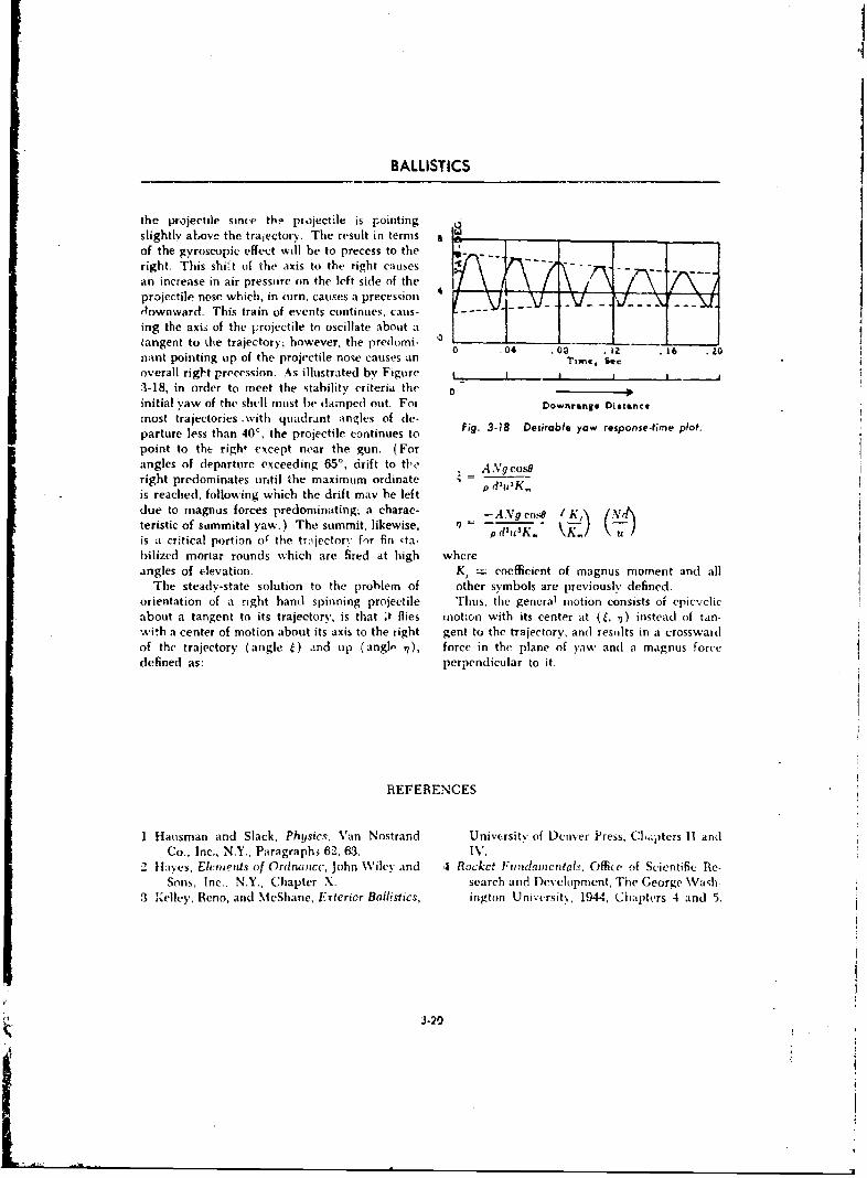
BALLISTICS
the projectile since tho projectile is pointingslightly above the trajectory. The result in termsof the gyroscopic effect will be to precess to theright. This shirt of the axis to the right causes-an increase in air pressure on the left side of theprojectile nose which, in turn. causes a precession . _ x _downward. This train of events continues, caus- ..
ing the axis of the projectile to oscillate about atangent to the trajectory; however, the predomi- 0 .04 .0 .12 .i6 .
nant pointing tip of the projectile nose causes an Time,. Secoverall right precession. As illustrated by Figure i I___I____3-18, in order to meet the stability criteria the oinitial yaw of the shell must be damped out. Foa Downrange Diatancemost trajectories .with quadrant angles of de-parture less than 40', the projectile continues topoint to the righ, except near the gun. (Forangles of departure exceeding ,5', drift to t6,e . _ AVg cos8right predominates until the maximum ordinateis reached, following which the drift may be leftdue to magnus forces predominating, a charac- -AVg cosh / Kteristic of summital yaw.) The summit, likewise, ml -
is a critical portion uo the tr:ilector,. for fin ,ta- u kbilized mortar rounds which are fired at high whereangles of elevation. K, c-= coefficient of magnus moment and all
The steady-state solution to the problem of other symbols are previously defined.orientation of a right hand spinning projectile Thus, the general motion consists of epicvclicabout a tangent to its trajectory, is that .t flies motion with its center at (ý, ,7) instead of tan-with a center of motion about its axis to the right gent to the trajectory, anl results in a crosswardof the trajectory (angle 4) and up (angl- 7), force in the plane of yaw and a magnus forcedefined as: perpendicular to it.
REFERENCES
1 Hausman and Slack, Physics, Van Nostrand University of Denver Press, Ci.-,)tcrs II andCo., Inc., N.Y., Paragraph3 62, 63. IV.
2 tayes, Elements of Ordnancc, John Wiley and 4 Rocket Fumdamcntals, Office of Scientific Re-Sons, Inc.. N.Y., Chapter X. search and Development, The George Wash
3 Kelley, Reno, and MeShane, Erterior Ballistics, ington Univcrsity, 1944, Chapters 4 and 5.
3-20
44
CHAPTER 4
BALLISTIC AND AERODYNAMIC TRAJECTORIES
4-1 INTRODUCTION
The existence of guided missiles which fly man or recovering instruments or films from abalbstic and aerodynamic trajectories dictates satellite orbit is by means of a vehicle deceleratedspecialized treatment of these flight paths. and supported aerodynamically.Moreover, interest in long range hypervelocity This chapter deals briefly with ballistic andvehicles has in.creased with the successful launch- aerodynamic (cruise) missiles and with theing of earth satellite vehi.:les. At this writing the hypervelocity vehicle which is part airplane andonly technically feasible means of returning a part spaceship.
4-1.1 BALLISTIC MISSILES aerodynamic type missiles were restricted to sub-
A ballistic missile is herein considered as a mis- sonic speeds, but at present, speeds of approxi-sile which follows a ballistic trajectory after mately three times the speed of sound car, be
thrust cut-aff. Prior to thrust cut-off, the missile attained. The speed and altitude characteris-may be directed to a predetermined point in tics of aerodynamic paths in general, are shown
space where its ballistic trajectory begins. It in Figure 4-1.
may also be capable of slight path correctionsduring its terminal fall through the atmosphere.l,ike the artillery projectile, it has essentially Hypervelocity vehicles capable of tremendouszero lift at the compltion of its propulsion phase speeds, have two very attractive features: shortand from that point is subjected only to the time of flight and vern !ong range. A satelliteinfluenceF of its momentum, gravity, and atrios- vehicle, for example, can obtain arbitrarily longpheric conditions. For short ranges, the crdi- range over the surface of the earth with a finitenate may reach 50 miles; for long rang, ,, the speed (about 18,000 nrph). The powered flightordinate may extend to 900 miles above the of a hypervelocity vehicle will probably employearth's surface. Ballistic missiles of long range rocket motors. Unpowered flight is characterized(sav 50(W miles) are called "lntcrcontincntal" by a ballistic, orbital, skip, or glide trajectory.(ICBNI). Intermediate range missiles (say 1500 The principal problem connected with hyper-miles) are called IRBM's. Speeds attained by ve!ocity vehicles is the dissipation of heat aero-ballistic missiles (and associated reentry prob- dynamically produced within the atmosphere.lems) are on the order of Mach 20. To dissipate this hcat,-specialized techniques are
needed, e.g., employment of a coolant floid.4-1.2 AERODYNAMIC MISSILES The ballistic trajectory is found to be the least
Consideration of trajectories for aerodynamic efficient of the several types mentioned, in thatmissiles must reflect the use of wings or airfoils it generally requires the highest velocity at thewhich produce a sizable vertical lift vector. This end of powered flight in order to attain is given!ift vector is the i:tjor contributor in supporting range. This disadvantage can be offset by reduc-the missile in flight. Aerodynamic type missiles ing connective heat transfer to the reentry bodynormally fly a flat trajectory which is sometimes through increasing pressure drag in relation toreferred to as a supported trajectory. Generally, friction drag (i.e., using a blunt body). Thus,this type of missile uses an air breathing jet en- the kinetic energy required by the vehicle at thegine, Missiles of this category are often referred end of powered flight may be reduced by mini-to as pilotless aircraft and may resemble con- mizing the mass of coolant material which mustvcntional aircraft in configuration. The early be carried along.
4.1
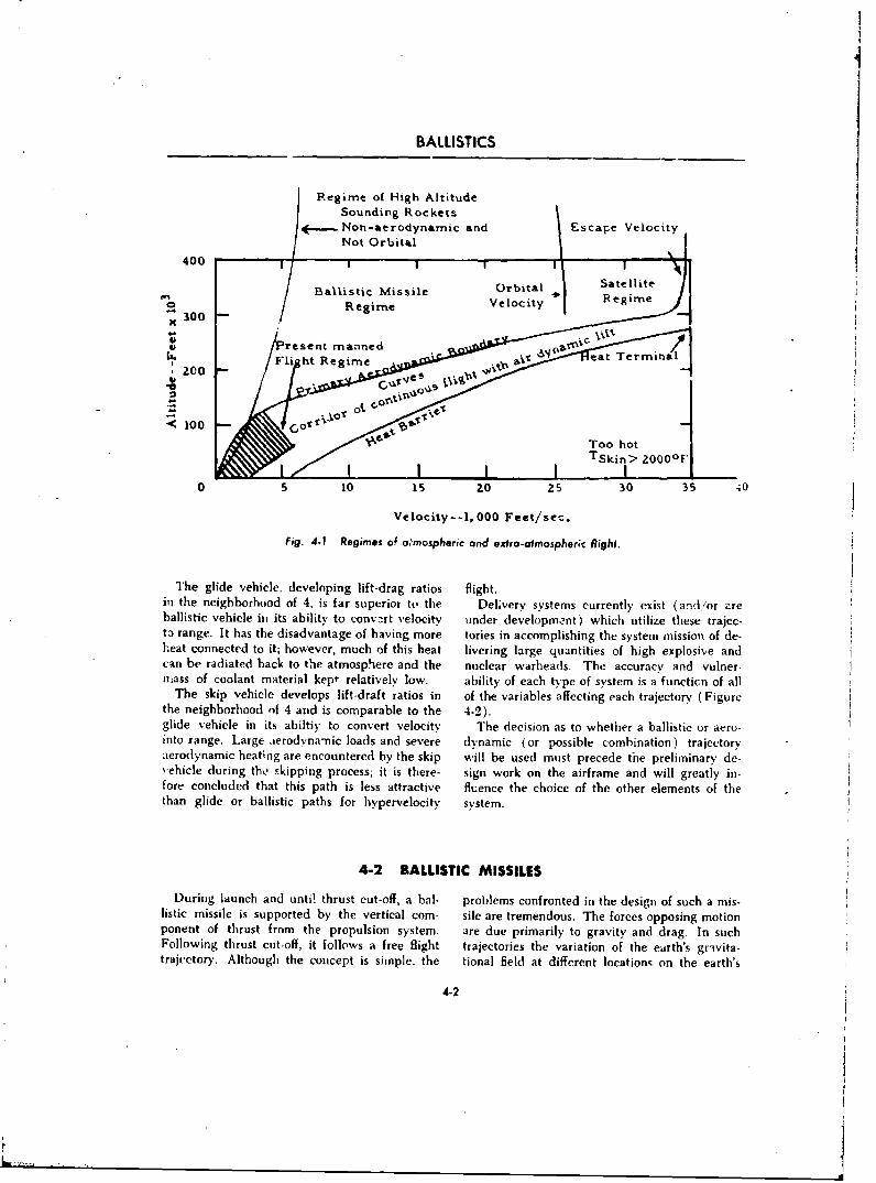
BALLISTICS
PRegime of High AltitudeSounding Rockets
/.-,---. Non-aerodynamic and Escape VelocityNot Orbital
400 1 - I r
Ballistic Missile Orbital Satellite
/Regime Velocity Regim
X 300V /resent rma.nned .
Fli ht Regime Vc retT mia, oo 'es., ... •,"•-•-
100A
TSkin> 200OlF
05 10 is ZO 25 30 35 ;0
Velocity--1, 000 Feet/see.
Fig. 4-1 Regimes of o.'mospheric and extro-atmospheric flight.
The glide vehicle, developing lift-drag ratios flight.in the neighborhood of 4, is far superior to the Deliverv systems currently exist (and/or zreballistic vehicle ill its ability to convart velocity tunder development) which utilize these trajec-t3 range. It has the disadvantage of having more tories in accomplishing the system mission of de-heat connected to it; however, much of this heat livering large quantities of high explosive andcan be radiated back to the atmosphiere and the nuclear warheads. The accuracy and vulner-mass of coolant material kept relatively low. ability of each type of system is a functicn of all
The skip vehicle develops lift-draft ratios in of the variables affecting each trajectorv ( Figurethe neighborhood of 4 and is comparable to the 4-2).glide vehicle in its abiltiy to convert velocity The decision as to whether a ballistic or aeru-into range. Large ierodvnamic loads and severe dynamic (or possible combination) trajectoryaerodynamic heating are encountered by the skip will be used must precede the preliminany de-vehicle during the skipping process; it is there- sign work on the airframe and will greatly in-fore concluded that this path is less attractive fluence the choice of the other elements of thethan glide or ballistic paths for hypervelocity system.
4-2 BALLISTIC MISSILES
During launch and unti! thrust cut-off, a bal- problems confronted in the design of such a mis-listic missile is supported by the vertical com- sile are tremendous. The forces opposing motionponent of thrust from the propulsion system. are due primarily to gravity and drag. In suchFollowing thrust cut-off, it follows a free flight trajectories the variation of the earth's grivita-trajectory. Although the coucept is simple, the tional field at different locations on the earth's
4-2
I
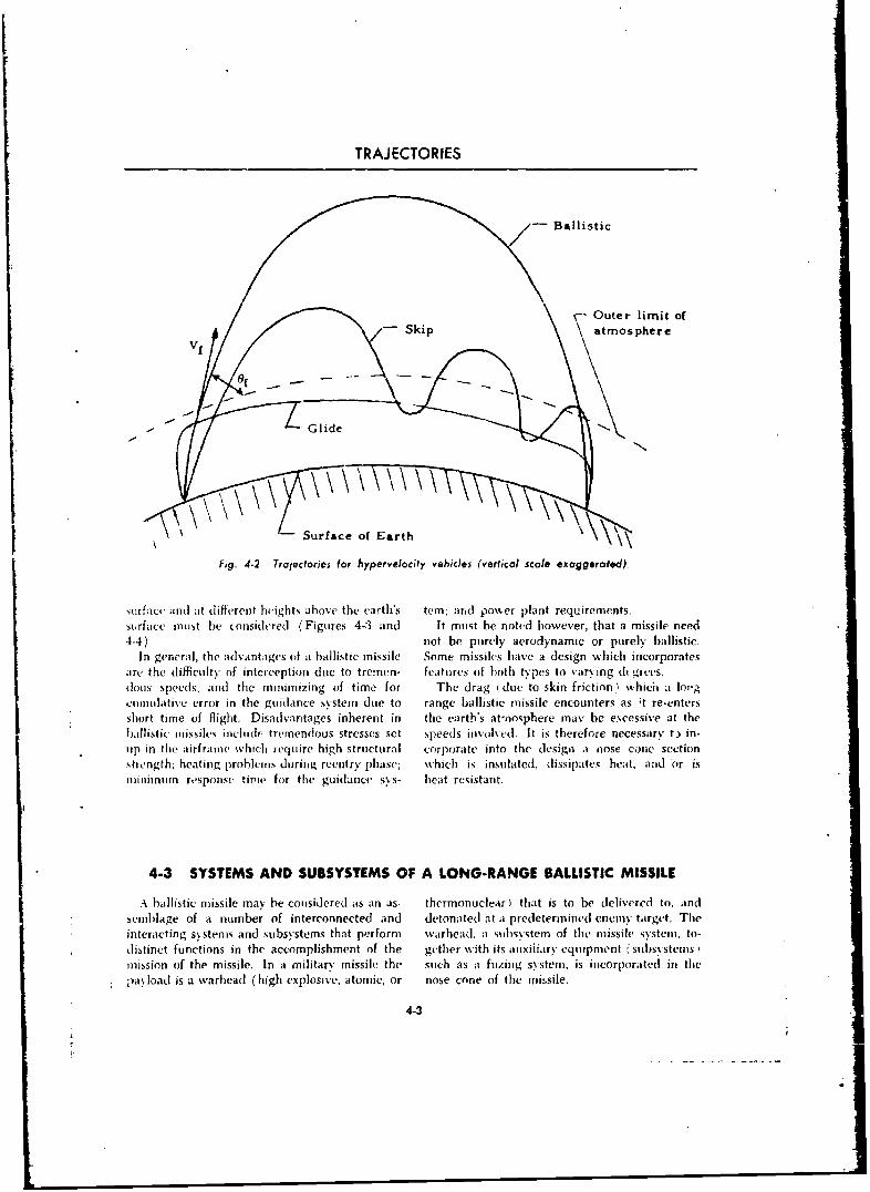
TRAJECTORIES
Skip atmosphere
-Surface of Earth
Fig. 4-2 Trajectories for hypervelocity vehicles (verlicol scale exaggerated).
surface ;an( at (different heights above the earth's tern; ar~d posker plant requirements.surface must be considered (Figures 4-3 and It must be noted however, that a missile need4-4). not be purely aerodynamic or purely ballistic.
In general, the advantages of at ballistic missile Some missiles have a design which incorporatesare, the diffiulty of interceptioni due to tremen- features of both types to varying d grees.dons speeds. and thle minimizing of time for The drag idue to skin friction. which atlo~cuumnulative error in the guidance system due to range ballistic missile encounters as ;t re-entersshort time of flight. Disadvantages inherent in the earth's atmnosphere may be excessive at theballistic uiussiles include tremendous stresses set speeds involved. It is therefore necessary t. in-up in the airframe which require high structural corporate into the design a nose cone sectionstrength, heating probleims during reentrY phase; which is insulated, dissipates heat, and or isminimuin response timne for the guidance sys- heat resistant.
4-3 SYSTEMS AND SUBSYSTEMS OF A LONG-RANGE BALLISTIC MISSILE
A ballistic missile may be considered its an as- thermonuclear) that is to be delivered to, andsemnibage of a number of interconnected and detonated] at at predetermined enemy target. Theinteracting systems and subsystems that pe-rform wvarhead, at subsystem of the missile systeimu, to-distinct functions in the accomplishment of the gether with its auusiiiaury equipment ;'subsystemsmission of the missile. In a military missile the such as at fuzing system, is incorporated in thnepayload is a warhead (high explosive, atomic, or nose cone of the mi'issile.
4-3
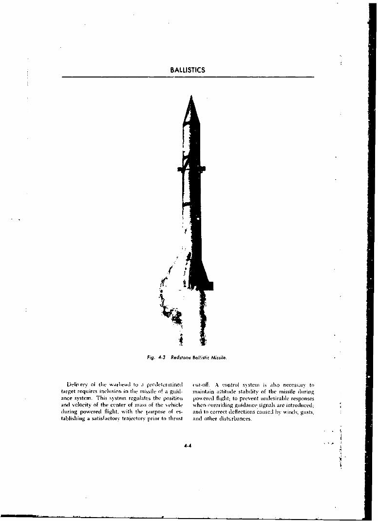
BALLISTICS
7.
•4 - "
Fig. 4-3 Redstone BaI!istic Missile.
Delivery of the warhea.d to a predetermined I cut-off, A control system is also necessary totarget requires inclusion in the missile of i guid- maintain altitude stability of the missile duringance system. This system regulatcs the position powered flight; to prevent undesirable responsesand velocity of the center of mass of the vehicle when overriding guidance signals are introduced;(luring powered flight. with the purpose of es- and to correct deflections causel by winds, gusts,tablisbing a satisfactory trajectory prior to thrust and other disturbances.
4-4
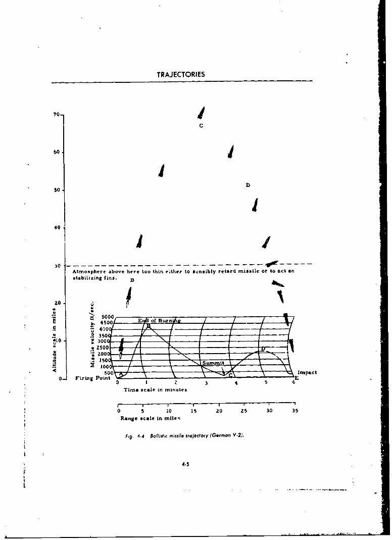
TRAJECTORIES
70-
C
60 j
D50
II401
Atmosphere above here too thin either to sensibly retard missile or to act on
stabilizing fins.
20 -
U
500
o 450s0, Enfiof Bur,,/e- .• 4 0 0 1 )
40 300 . .
0. Firing PointE
Time scale in minutes
I I I I N
0 5 10 15 20 25 30 35
Range scale in milen
Fig. 4-4 Ballistic missile trajectory (German V-2).
4.5
L
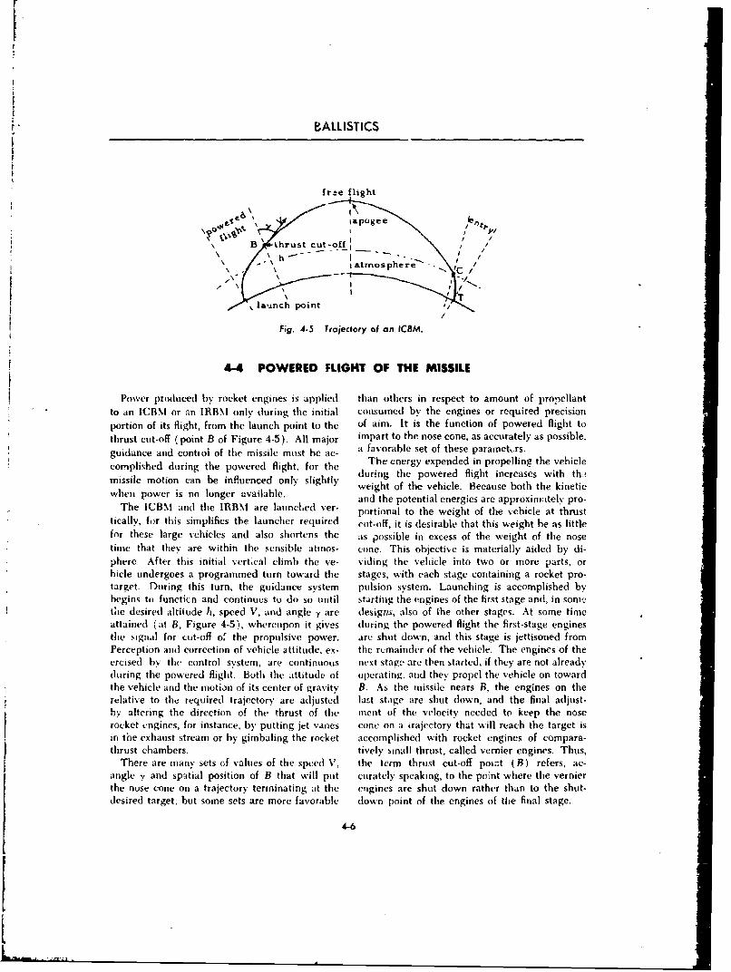
F
BALLISTICS
frse flight
i apogee Ike
B thrust cut-•off ,
\h-' I ,
Satmosphere'-. '-\ /
l launch point '3/
Fig. 4-5 Trajectory of an ICRM.
4-4 POWERED FLIGHT OF THE MISSILE
Power produced by rocket engines is applied than others in respect to amount of propellantto an ICBM or an IBB\l only during the initial consumed by the engines or required precisionportion of its flight, from the launch point to the of aim. It is the function of powered flight to
thrust cut-off (point B of Figure 4-5). All major impart to the nose cone, as accurately as possible,
guidance and contiol of the missile must be ac- a favorable set of these parametrs.
complished during the powered flight, for the The energy expended in propelling the vehiclemissile motion can be influenced only slightly during the powered flight increases with th,missilem on canoe nluongeravailysl il weight of the vehicle. Because both the kineticwhen power is no longer available, and the potential energies are approximately pro-
The ICBM and the IRBNI are launchled ver- portional to the weight of the vehicle at thrusttically, for this simplifies the launcher required cut-off, it is desirable that this weight be as littlefor these large vehicles and also shortens the as possible in excess of the weight of the nosetime that they are within the sensible atmos- cone. This objective is materially aided by di-phere. After this initial vertical climb the ve- viding the vehicle into two or more parts, orhicde undergoes a programmed turn toward the stages, with each stage containing a rocket pro-target. During this turn, the guidance system pulsion system. Launching is accomplished bybegins to functicn and continues to do so until starting the engines of the first stage and, in son)-the desired altitude It, speed V, and angle y are designs, also of the other stages. At some timeattained (at B, Figure 4-5), whereupon it gives during the powered flight the first-stage enginesthe signal for cut-off of the propulsive power. are shut down, and this stage is jettisoned fromPerception and correction of vehicle attitude, ex- the remainder of the vehicle. The engines of theercised by the control system, are continuous next stage are then started, if they are not alreadyduring the powered flight. Both the attitude of operating/. and they propel the vehicle on towardthe vehicle and the motion of its center of gravity B. As the missile nears B, the engines on therelative to the required trajectory are adjusted last stage are shut down, and the final adjust-by altering the direction of the thrust of the inent of the velocity needed to keep the noserocket engines, for instance, by putting jet vanes cone on a trajectory that will reach the target isin the exhaust stream or by gimbaling the rocket accomplished with rocket engines of compara-thrust chambers. tively small thrust, called vernier engines. Thus,
There are many sets of values of the speed V, the term thrust cut-off point (B) refers, ac-angle y and spatial position of B that will put curately speaking, to the point where the vernier
the nose cone on a trajectory terminating at the engines are shut down rather than to the shut-desired target; but some sets are more favorable down point of the engines of the final stage.
4-6
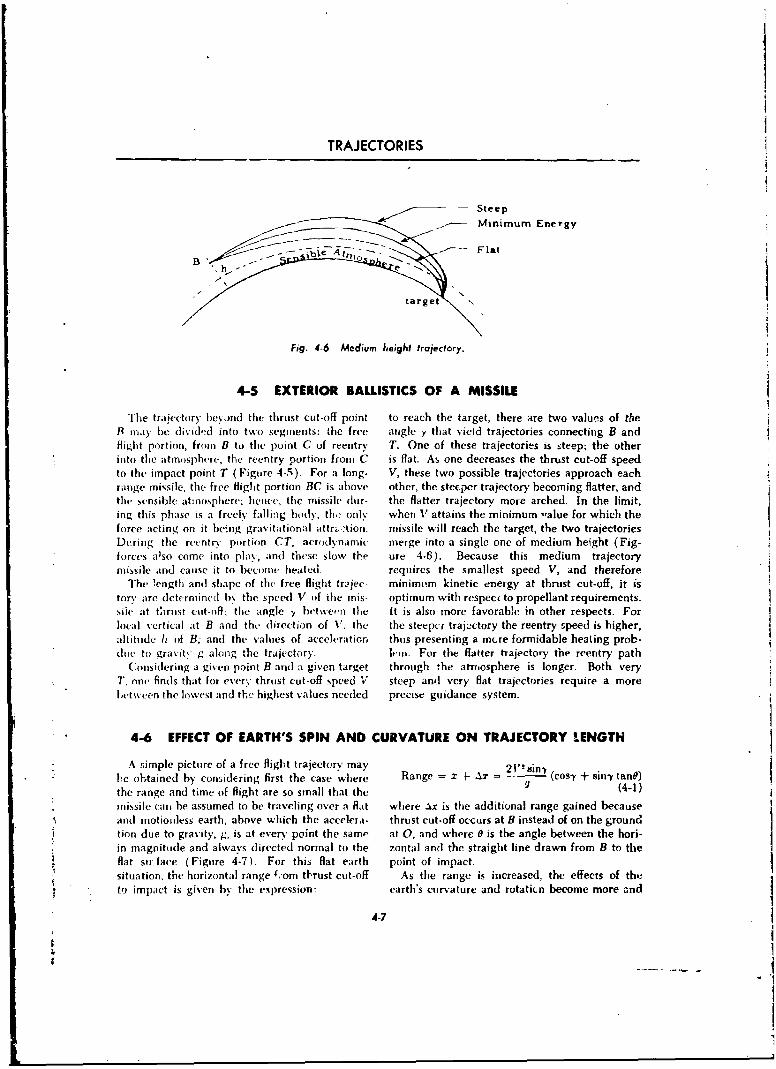
TRAJECTORIES
Steep
.•- Minimum Energy
Fig. 4-6 Medium height trajectory.
4-5 EXTERIOR BALLISTICS OF A MISSILE
The traiectory hey.rnd the thrust cut-off point to reach the target, there are two values of the9 may be dividd into two segments: the free angle y that yield trajectories connecting B andflight portion, from B to thc point C of reentry T. One of these trajectories is steep; the otherinto the atmosphere; the reentry portion from C is flat. As one decreases the thrust cut-off speedto the impact point T (Figure 4-5). For a long- V, these two possible trajectories approach eachrange missile, the free flight portion BC is above other, the steeper trajectory becoming flatter, andthe sensible atmosphere; hence, the missile dur- the flatter trajectory more arched. In the limit,ing this phase is a freely falling body. th,; only when V attains the minimum ,alue for which theforce acting on it being gravitational attrý.-kion. missile will reach the target, the two trajectoriesDuring the reentry portion CT, aerodynamic- merge into a single one of medium height (Fig-forces also come into play, and these slow the ure 4-6). Because this medium trajectorymissile and cause it to become heated, requires the smallest speed V, and therefore
The ,ength and shape of the free flight trjec- minimim kinetic energy at thrust cut-off, it istory artc determincd b\ the speed V of the mis- optimum with respect to propellant requirements.siie at tCwrost cut-off; the angle -y fetwern the It is also more favorable in other respects. Forlocal vertical at B and the direction of V; the the steepcr trajactory the reentry speed is higher,ahlitude h of B; and the values of acceleration thus presenting a mere formidable heating prob-due to gravit' g along the trajectory. k-in. For the flatter trajectory the reentry path
C(onsidering a given point B and a given target through the atmnosphere is longer. Both veryT, onn finds that for every thrust cut-off speed V steep and very flat trajectories require a moreLetween the lowest and the highest values needed precise guidance system.
4-6 EFFECT OF EARTH'S SPIN AND CURVATURE ON TRAJECTORY I.ENGTH
A simple picture of a free flight trajectory may 21" Bin-,
he obtained by conidering first the case where Range = z + Ar (cosY + sin-y tane)
the range and time of flight are so small that the (4-1)
missile can be assumed to be traveling over a flat where Ax is the additional range gained becauseand motionless earth, above which the accelera- thrust cut-off occurs at B instead of on the ground
lion due to gravity, g, is at ever' point the same at 0, and where 0 is the angle between the hori-* in magnitude and always directed normal to the zontal anti the straight line drawn from B to the
flat stiface (Figure 4-7). For this flat earth point of impact.situation, the horizontal range ý,'om tbrust cut-off As the range is increased, the effects of the
to impact is given by the expression: earth's curvature and rotaticn become more and
4-7
--. -
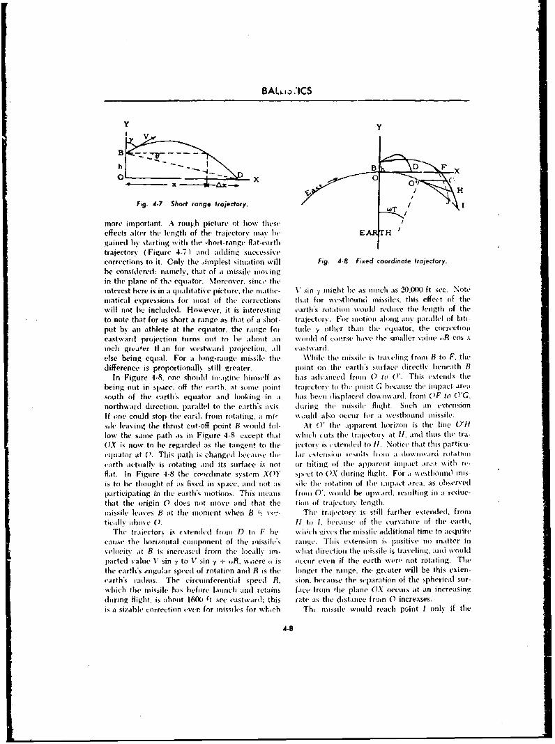
BALi3.i)CS
Y y
B
h -D. I D Fx
IH
Fig. 4-7 Short range trajectory. w
more important. A rotipb picture of how theseeffects alt .er the length of the trajectorv may he EJ Hgained b% starting with the -hort-range flat-earthtrajectory ( Figure 4-7)1 and adlding suiccessivecorrections to it. Only the Admplest situation will Fig. 4-8 Fixed coordinate trajectory.be considered: namiel, that of at missile imuingin the plane of th,- equator. Moreover, sinco theinterest here is in a qualitative picture, the miathe- V sin -, vuitlvt he ats much its 20,000 ft sec. Notemiatical expressions for most of the corrections that for westhouino mIissiles, this effect of thewill not he included. However, it is interesting earth's rotation would redlc'C the length of theto note that for ;is short a range ats tha1t Of it shot- trajectory. For inotiou ailong an) parallel of latti-put by an athlete at the equator, the range for tude y other thani the equator, the correctionieastward projection turns ont to he about an wvould of couirse have-( thc smaller value ~.R cos xinch greiter ti an for westward projection, ;ill eastxvard.else being equail. For at lung-range inissile tihe While the missile is traveling front B to V. thedifference is proportionall\ still greater. point on the earth'% stufavce (ireectlv beneath B
In Figure 4-8, one should ilmagine himself a% has% advanced from 0) to ('. This extends thebeing out in space, off the earth. at some point traiectory to tho point G because thme impact areasouith of the earth's equator and looking in at has been displaced downw.ird, from OF to fl'C.northwvard dlirection. parallel to thme earth's axis. hiring the missile flitght. Suich ain extensionIf one could stop the can], from rotating, at mi' \% oild also occur for a wvestbound mnissile.s~le leaving the thrust cut-off point B wouild fol- At 0' the aipparent horizon is the line UP1low the samne path as in Figure 4-8. except that w~hich cuts tile trait-ctor\ at 11, avid thus the tra-OX is now to he regarded as the tangen! to the iectors is cxteiided to 11. Notice that this particum-eq oat or it (i~. Tb is path is changed b eca sct: tet Ia r c.xttem-o viimeso Its fr iii a dow ii wird rotaUtionearth actually is rot atinig amid its surface is not or ti;ting if the apparent inmu pact area wkithi rv--flat. In Figuire 4-8 (he coor-dinate, s 'ystemn XOY slimct to OX duriniz flight. For at ss sthoin(1 mis-is to he thought of os fixed in space, 00(1 not ;is suev the rotation of the iiipaiýt ,vreýa. as obiservedIparticipating in the earth*% motions. This means fromt 0'. wouild he upward. resuilting in a reduc-that the origin 0 does not move and that the tion oif trajectory length.missile leaves B at the moment when B is x'e7- The trrlectorv is still farther extended. fromticilly abuse 0. 11 to 1, hilejikse (if the euirvatumre of the earth,
The tr,kiector% is c stended fruoit D to F he- _,iciti-s the missile additional time to acquirecause the liorizontal component of the r'isls range. This extension is positive no mai~tter inveliocitv it B is increased from the locallv im- whait direction the iritsile is traveling, anid wouldpartedi value V" sin y to V sin y, %,, s.oere , is occur even if the earth were not rotating. Thethe earth's .vnguhmr sp('cd of rotation and R is the longer the ranige, tht- grcater will be this exten-earth's madins. The circumferential speed R. sion, because the separation of the spherical stir-which the missile hams before launich and retains face fronm tile plane OX oceni s at an increasingduiring flight, is about 16(Xi ýt sec eastw.ard; this rate ;is the distance fr'uin 0 increases.is it sizabhle' correction e-er. for miissiles for wh,rb Th( imissile would reach po~int I only if the
4.8
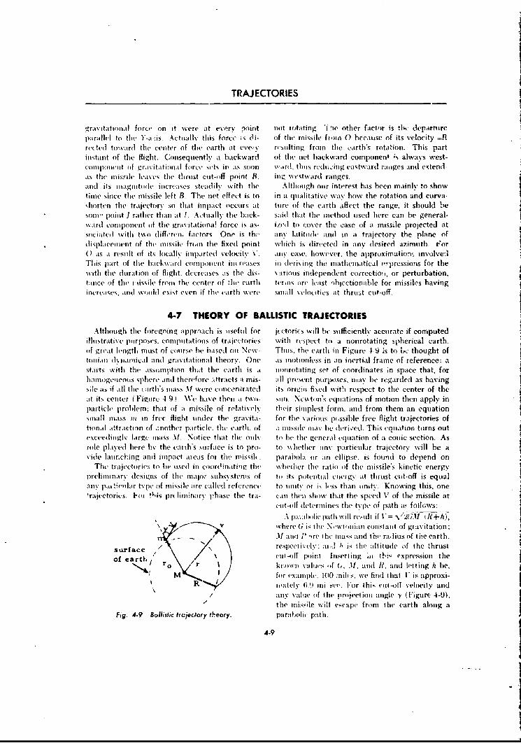
TRAJECTORIES
gravitational force on it we~re at every point not ilutatiflg. 'f !ie other factor is tlic depaSrtulreparallel to tilt )'-a is . Actually this force is di- of the- missile fton 0) because of its velocity _flrecteti tow-ard the center of the earth at evey v resulting from the earth's rotation. This partinstant of the flight. Consequently at backward of the net b~ackward component is always west-coin 1( hIIC I t of gra s-it at lolll foirce sets it ats soon wardl thus red n g eastward natiges and extend -as the inis~ie leaves the thirust cut-off point B, inv westward ranges.anti its mnagnitud~e increases steadily with the Although our interest has been mainly to showtime since the missile left B. The net effect is to in at qualitative wayt% how the rotation and curva-shorten tihe trajectors- so that impact occurs at tore of the earth affect the range, it should be%ou0!' point I rather thlan at I. Ac.tuallN the hack- said that the method uised here can he general-wardi comlpnnent of the grasutationa! forcc is ats- ized to cover the case of it missile projected atsociatei I with two differemi. factors- One is thv ansV latitude and in at trajectory the plane ofdisplacemirtnt of the mnissile frm-i the fixed point which is directed in any deCsired azimuth. For
a)is at result oif its locally imparted velocity C. amis cas.'I Ihowever, the approximatiolfl, involved.Th is part of the lbackv~aidi c0101 )hiltt in(Lreat*5 ill deriving tilt niatheroatical v~pressions for the\%ith the duration of flight. dlecreases i:s the dis- vairiuos independent correctio-i, or perturbation,tance of the t nissile front the center (if 'lhe earth terms atre least ibjectionable for missiles havingincreases, and wvouldl exist even if the earth %%sen- smalli \eloc itivs at, thrus:t cot-off.
4-7 THEORY OF BALLISTIC TRAJECTORIES
Although the foregoing appraach is i1seflil for jeetories will he sufficiently accurate if computedIllustrative puirposes, compuitations of traiiectories with r(Lspect to a nonrotating spherical earth.of Lgreat lentgth must of course he based oni New- Thus, the earth in Figure 4-9 :s to 1,,c thought oftil Iian iIbln1am~ical and gravitational the iory. One as m ot ion less in a i inert ial frame of reference: astarts with the assumption that the earth is a. mionrotating set of coordinates In space that, forhaniogerinuis sphere and therefore .-ttracts a mis- All present purposes, mlay ibe regardedt as havings;eit s if all the i rth's inass At! wiere concentratedl its oriigun fixed with respect to the center of theat it. center ( Figure 41-9 ). We hlave thlen a two- son. Nesston's e-quations of motion then apply inparticle probllem; that (If at missile of relaitiv ely their sihplpest form. and from them an equationsmnaifll a~ss InI in firee flight tinder the gravita- for the various pu~ssible free flight trajectories oftionral attraction (If i-nother particle-. the earth. (of a mlissile illav be de-riýved. This equiation turns outVcxee-dinglv large ~iass --If Notice that the only to he thle general equation of a conic section. Asrole play-d here hv the earth's surface is to pro- to .\ilt-ther anN particular trajectory will be aside laurehing anti imipact itieas for tilt rnissil. parabola or an ellipse, is found to depend on
The trajectories to iC lisetI in coordlnati'lg the, whlether the ratio ofI the missile's kinetic energyprelininarv designs of tilt majior suihsrst(-n~s of tol its pote-nitial energy at thrust cut-off is equal
ainy piol tveular type (of miqsile are called reference to iility or is lr-ss than iinit:y. Koos-wing tihis, one'trajectories. l'oz !Iis pr( liminary 1-hase thle tra- Can !heal %hov.w that the, speed V of the missile at
cut-oiff dletermiine-s the type of path a'folhlsvs:A paral vilic path \%sill resuilt if V="2M
.11 and~ P -I re ilthe nass and tI-b rad ius oif thie eart h.
surface respect ivek ::it,! h is the at it ode olf the thrulstof earth, eliii-4 poinit insert hg ii tte' ('spressioll the
0 r Iknownl values, If (1. 11. aild le, aiid HIinig h he,Mv for example. 1010 miles, we find that V~ is approxi-
R ue~ately fi.9 mi sce. Foir this Celt -(It velocity and/ ~ainy vailue of I he Project ioii angle -y (Fi~gure 4-9),
the missile 16!l escape from lie earth aloing a
Fig. 4.9 Balfistic fircieclory theory. palrabo~lic' path-L
4.9
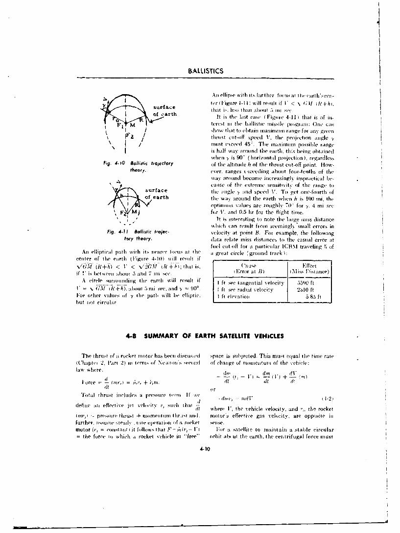
BALLISTICS
Ali ellipse with its farther forlus :1Io l rhse
surfacet vr ( Figure 4-1 I ) will resulIt if V < ( ;-If W1+/i).V ~urfac t hat i>.le. t han about 5j 111 sec
o ath It is th laist cse (Figure 4-11) that is of in-tertest i a the hallist ic missile provru i:OeL
I show that to obtain maxit-urot range for an%. givenJF I thrust cut-off spceed V, the projection atngle *,I/ rounst exceed 45ý. The inaximorn possible range
is half way' arotindl the earth, tli~s being obtainedwhen y is 9W~ ( horizontal projection ). regardless
Fig. 4-10 Ballistic Via jectory of the altitude It of the thrust cutt-off point. flow-theory, ever, ranges txeeding ahout four-tenths of the
W6aS' aroutnd become increasingly impractical be-canse of the extreme xt- snsitiv'ity of the range to
surface the ý-ngk. y and spe-ed V. To vet one-fourth ofof earth the way around the earth when It is% 1(0 mi, the
V ~optitnuro. values are roughly 70' for y. 4 mi sec
F2. F ) fcr V. and 0.5 hr for the flight time.
Fig. -It is interesting to note the large mniss distanceMhich (an resuilt from seemingly' small errors in
Fi.4-11 Ballistic toe-velocitv at point B. For example, the followingfory theory. data relate miss distances to the casual error at
fuel cut-off for at particular ICHNI traveling ;~ ofAu elliptical path with its nearer locus -at the a great circle (grouindI track)
center of thle earth ( Figure 4-10) %%ill result if _____________________-
~~u (-j~~ < <'v! I?-j-h; that is, ('a 11,e Effectif +_ is bv <el lOi .)aF u e rror at B) i % iss D~ist ancer)
A circle surrounding the earth will result if I ft sec tangeut ial velocityv 35540 ft_h'G] +), lthout 5 oP szec. and -Yz 9* ft sec radial velocity 2i00 ft
For other values of -y the path will be elliptic,. ft elev-ation 5.85 ftbut trot circular.
4-8 SUMMARY OF EARTH SATELLITE VEHICLES
The thruist (if it rocket miotor has becti uiscu:aaid space is subjected. This must equal the time rate(Chapite 2, P'art 2) in terms of Ncvton's sec~tal of chatnge of momnentum of the vehicle:law where; de -I - d rLn (IV) + dV
l-orce - +o.t=At j i"711 dt &d"I or
Total thrust inceludes a pressure term If wev- don, 111,41, 4-2.1
dett t ai efet ise~etvet ctyr~ o h tatdi wherei V, the vehicle velocity, and ' hý,te rocket
(mr,', :- pressure thrust + momrentuinu Ibr-ist aind. motorsz, effective gas v'elocity, are opposite infurther, assume st ead ' .t rtev olwrtimio of a. rocket NouseImotor ft, =conist ant)t it followAs that v ~I,-I) For a sat ellite to maintain a stable circular
=the force to which A rocket veLhicleC in "f ree' orbit abi ut (fth, earth, the cer.trifugal force must
A-10
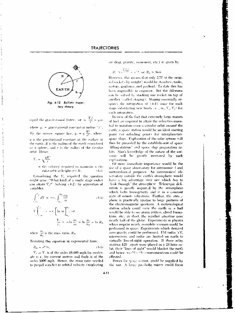
TRAJECVORIIES
Ar drag. gr;Ivitv, fiarlulver, etc. )is g~iven h,.
ro
aER h I ILL ini pw imb le to *nigi ut-cr. Bui t the di lemma
/ ~ ~ (I abc mIve~dsv Iý %t ackLi ng one, r ckeCt on top of
Iinotlier a allcd stat.ýing Staving vssentia.ill re-Fig. 4-12 Ballistic tra jec. 'fie l(iitriiiio 44 oc o il
tory theory. tpor'lstttii us v 0w ttitits o 44,. onceX X for ec
CMIth iltegratimfI.
ef iI: I I e r;I vi Ii tI Io II; I o.In \-i(,\% of thec fact that extremnely large masseslie 'r~ ci it iiiil f rc(or H ~ ' '~ of foil( ..rc eijiiiredl to a tta in file velocities essen -
where q, = grAVitat anat:l eoW-111 a:l 1 radikluci ti~l to minfiitaini tven it circular orbit around theR -, ~ C~itrtli. asice N sCCtat inn %Vouihi beV an ideal %tarting
1~ ~ ~ ~ ~ ~~f tsleivjvS lnhw ,= - ee Point ( or ref neluig poIinit for inti'rplanetarv
it i Ii(- graY it tifIOial en list ai t att 01ie Sf1rf;a0i Of spacc %h~ips. Exploration of the solar syster %sill
the( earth; R i., the radiuis (if fthe earth confsidlereud thus he preceded by the establishi.ent of spacea, aI sphere. aiid r is thei radius. of the ci.-olaur "fillirig-statinns" and Space ship prepariation or-flrkifi I knce bits. Mian'% knowledge off thle nature of the uni-
% virse will he greatly in creased by suchc 1 1, CS P a I t i ofits.
Of more ininiiediate importance would be theIi,, elct refiniref it)f mauiitniiu -I (ir- -wftasaensraov for astronomici -1 andcu1 oiirbit ;It height r- le, 4-3 inteffriolfviei( purp)oscs. Ali astronomnical, oh.
* (mCns~dei.rng the V., ri-quire&. tlhe quiestion scr5Itofr\ oiitside the earth's atmosphere wouldar~ltirse:V "hat kind ofita single Stage rocke 1%a(h a big adv'antaige over one which has to
can attain ~ YSolving t4-21 by separation of -ffok through" the atmosph( re. Telescopic dtefi-~ariaihles. nition is greatly iinpair-ýd by the atmosphere
dl ~which lacks homnogcneity anli i- ill a co nstantb~~l state ef ininuit vibrations. Further, the atmi-
'a phere is practi-ailv opaque to large portions ofthe elect romagnet ic spectrum. A meteorological
/ F 1! station which cfiuild viewv the earth as A ballifi In . or wotld be ablel to sec stormn centers, cloud forma-
tios. tc- inshotthe weather situation over)flj ff uearly hai ot(f the globe. Experiments in physics
= In = In In Rff iljwhici' requ re nearl, complete vacetuum Could, be
pe rfo 010(1 in space: Experiments wehich demnand
whlere is the marat iof., ze ro gras itN couldl be performed. [I\ radio. YV,1?f. microwsasves, and( radar are limnitedl on earth to)
Bestatting this equation in exponential form; virtualls line-of-sight operation. If three relaystations 12'0 apart were placed in aI 24-hour or-
I?-5) bit, thecir "lineý of sight" would blanket the earthV, - V, is of the order 18.000 inph foi inoder- and hence. % ssA,'l-.1 -onnuinications could be
Mte r; t: for current motors and fuels is of the effected.order 500)0 mph. Hence, the mnass ratio nieeled Power for qp-tcc si ition could he supplicd byto propel it rouket to orbital velocity (neglecting the sun- A large pa; fbolic mirror could focus
4-11
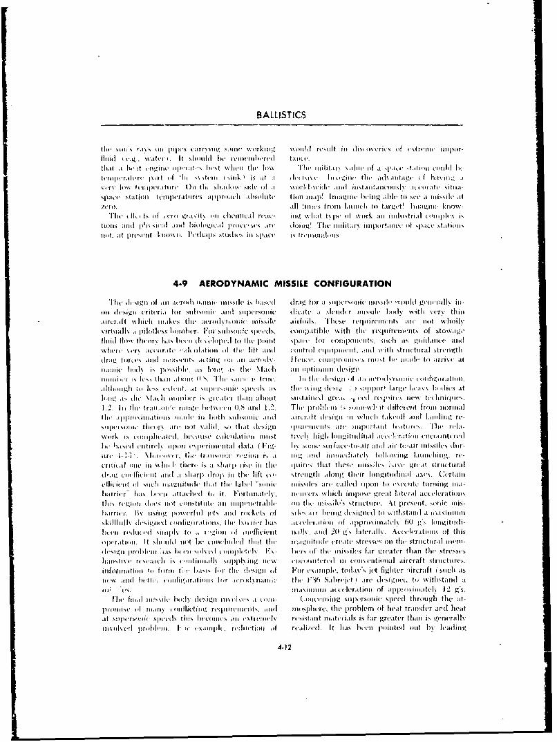
BALLISTICS
tltt sonsi r;(%s ont pipis) ciirrylott. Not' work-ilIg Wtnl~ 'Nit ill (li~t0lvritci of '\tr'int iiipnr-
flui 1. I so id le rm b rd tall iliec rnlIiicit al.tt lntlt kiwfla I "itvt tliif nt'r 14r.itihi bes lw~wiealli loxe 'I'll t H-llt~tt \ %illni w ork li i m'1,01011 U(ttIltjit. b
tci p-rertIt, c 1 ~~iii at ' tI ofrttI 'hl( %iiiiI(sok) is t ;t dc z i~irf c. I loe tv ' tlli r th ii.tad% .1tlre ( lit lv iiiv"k -r\ aaliv ftjipertttr' c ()iiitr Etit, \llittttl siltdc o (I ullai~ anth tiitartil irelwius ts m oft Nit~wtgt
spatltutiigaitit list c!i'tIlkt -ra t 1 iti Iti p(iah .t I)sol ot(s i tillt siligp deszw~nt hei l" ahp~ lare lto u it misile at
sZ ik i ttiiititt. it'aie ailtimih. tvll] 'iiiicsfo h mi chti tioa ,tat~rl.zltli hoitoctsint'r
l he t)5~( f 'ilttINiof ill it i').t'ruiiti ihilti c- niz \ ihiltc\' p oii fa twoirk auti gin-ot-ir ialcomplex dis
ti'tigii andhluu ] \ iul litIdl tiole ogii, I iovisis'e ~ I Ins tifg tue ttii'it.tfar% in .rtanter tha thii' stationsinistiat- pri-et.atI Ln s t' 'citiitiall' tu isi i ll spac. c n iw uil~euuilteti l dh'litt,1 icrf srslr
Theftlr itiii ot f ~ivroi t nim i~s'ft misile i''iii h f dra fr it-slili N ttti,ir-s et fighterul ti eoraft ~ IS ill-atoi dcigii ittitt e tai fo rttibsonittr tt'tt' u i-~i-so ic dicite l--t slilnril' ar tlt-si gne b hi, % t itscr itthinlrri ft\hc apsti( co ~ o i ('Sil alirfolis. aths reiler irnwto i ont i ati,int'l 12 gs.
%itoall' a l iliittPssii lomnt r. tlFior jiittt.tsol I tpodl- uoinptibl 1111 N 111t'r~i pe hth the rq ie w tso oat-
P~Whf %,-r litalir e titiiile tiiit r oflirli l'ifts tilt contrlls)li h c joirtibe an f ,iezti stransferl trcngheaita sfjtrslit- II )'t( hs iw ot, a t'etsiit' all it art'tiel rt-icut,lt io piiutriu is(, far t gre ater t oii is gi'n'railv
iino o rist' lu 0 11 jiuti tti. o 0"' '-Itlipct nu ieji (ol, nIllii cd cItn has Ilt-eii pninitetl ttnt byiLlataingl
altollh ' Iv, 40co. a N p-lollc " et-i; ts it-12 ii ci o p r arvl~ xkhisa
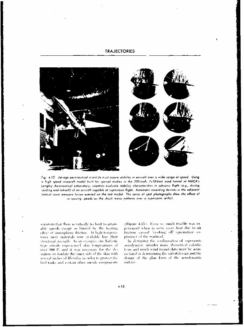
TRAJECTORIES
Fig. 4-13 Jet-age aeronautical scientists must assure ilobulity in aircraft over a wide range of speed. Using
c bigh speed research model built for special studies in the 300-mjah, 7x10.f cot wind funnel at NACA's
Lcngley Aeronaoutical Laboratory, scientists evaluate stability characteristics in subsonic flight (e.g., during'conding and takeoH) of an aircraft capable of supersonic flight. Automatic recording devices in the ad~iocentcont~ol ioomn measure forces exerted on the test niodel. The series of spot photographs show the effect of
in reasing -;peeds on the shock wave Patterns aver a supersonic airfoil.
,uieiiit,;t (.Ldt thesre- is %irtoially no limit to attaini- F i~isirs 4-15). lvii No. nindi ti ro.,Ol "its edx-
able speed"5 (-\ctpt as IjinsliC( I)% the( l~ieLtui"IL piriunct-il lsin Niwi sms vie bieat siuc to itir
ei-uc u(i atinosi-plerit- friction. At Ligis teusili-rai. frictiion caiised."(ositzis 14" ipjrematilic ex-
till(- isost miaterialis sow% tivailablc lose their pioiion ) if thc Nvarlieni.
!Trl:(tiiral Alisui~Lflu .i, As i all i~'. ill]( bsalhn'tj Ini di'vilý11iinl. 1ist (ifgldiul . ipas~i
tvlss inissile va- srielijcd' skill tiinspciatisres oif ,acri)1i'dithiiii m~issiles IIanos tlicuiretisxil1 e'Altllid-isv(-r 90(0 F, and it %vas nucsisaro,i for t~li' (I(- Gillis and
11usiiisis wills] boile!- slila linist he amci-
siLsnrlsr Ito jimiiLite the inike(r Side* of the skins %vithl siniliatt-s ill ulsterniniiiisa ic ite irfoil (l~iji~fan .itheii
%v~ciai iiodic, iif fjiwrglbgs i~i iurdcr to protti-o tie (lesii (iuf tilt plant furnis oif thc i-rullinar-nic
foil tantks andusi-(rtuill itlir ilisshiic ssiiponiieats siarfilue.
4-13
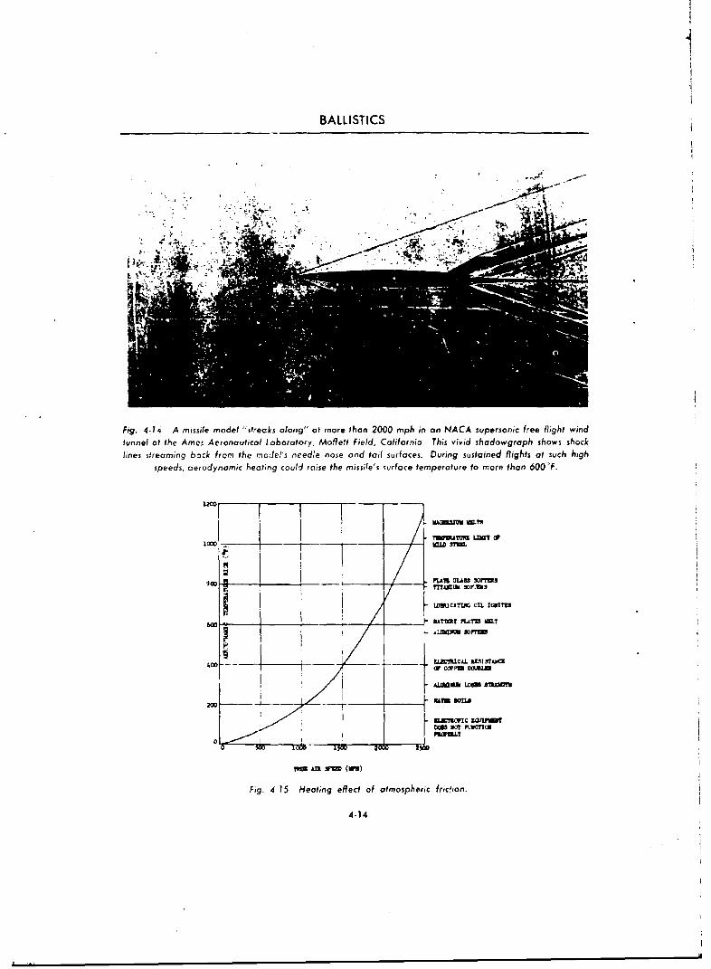
BALLISTICS
Fig. 4-14 A missile model "strecks along" at more than 2000 mph in an NACA supersonic free flight windtunnel at the Ames Aeronautical Laboratory, Mofie't Field, California. This vivid shadowgraph shows shocklines streaming back from the moJel's needle nose and tail surfaces. During sustained flights at such high
speeds, aerodynamic heating could raise the missile's iurface temperature to more than 600SF.
Isom? LDU --
a4-1
SPLAN MASS 50110
p A?Wz5 ?LArI MX.T
£t1iCML L flSISTAiiCKcr COPua wjsMM
A=flM& C ~S Ufl0!
0 ' - (, I)
V=W AM M(H
Fig. 4-15 Heating effect of atmospheric fridison.
4-14
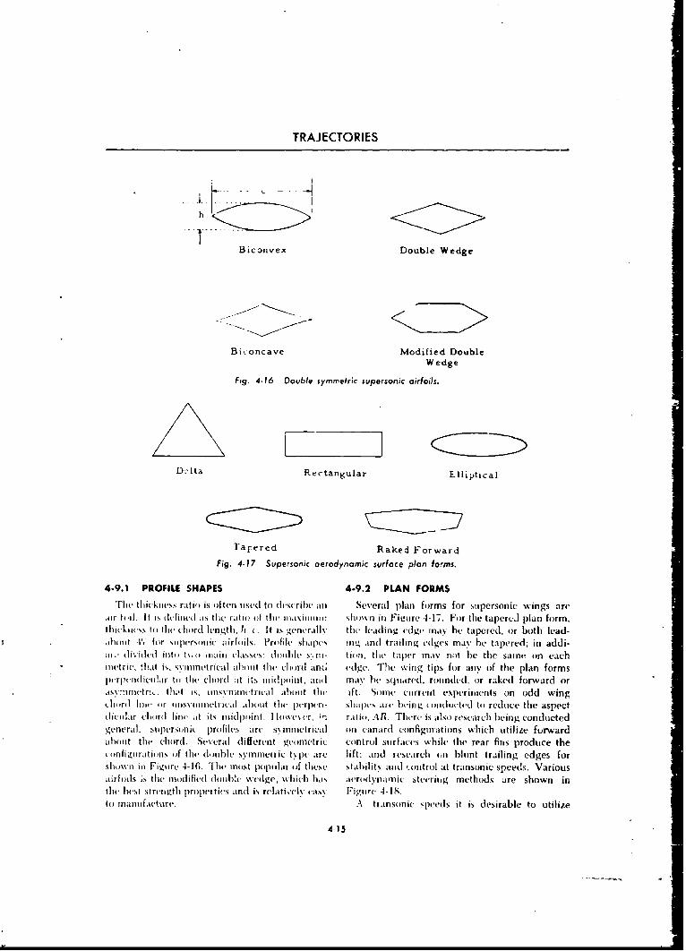
TRAJECTORIES
I-
h
Biconvex Double Wedge
Bi.oncave Modified DoubleWedge
Fig. 4.16 Double symmetric supersonic airfoils.
D. Ita Rectangular Elliptical
Tapered Raked Forward
Fig, 4-77 Superson'ic aerodynamic surface plan forms,
4-9.1 PROFILE SHAPES 4.9.2 PLAN FORMS
Th~e thic ikness ratio is often lits(,( to (describei an Several plan forms for supersonic wings are.ir itoI. It is dfib V Io aiiS the r 'aiti I(I O thIIu I iiaXiI II I III shiiss n in ligiire 4-1IT. For the tapered plan form,liickiicss to tit( (liord ieflgthl. It (. It is generall-v tite leadling edge mnay he tapered, or both lead-
aboujit T', for siiperson ic airfoils. Profile sliip(s ing and] trailin~g edges may be tapered; in addi-M '(1%ivdud ino t\ i o IIIT (a in % S(Ss: hum ib Ic s-, nII- tion, t Iit( taper mnay ni)t he the samse on each
ii ut r i c that is - ss ntnet rica id abou t tlecii diord am; (a dge. vhe wing tips fi r any of the plan formsor i -piiici I iclr to (t I i cihordh at its midpoinst, and at oa be squoared, rioti fled , ior raked forward or
.iss umnit ri t It ids, usiiin inhsct rica aboull t tit(. i ft. Soincri ciirrciit esp('r inie nt s on odd wing(III jrIIit I lii (Ir I IINNS Ii liiiIt I Wilal J b( 't t I ic purpen- SlIJi a are lbiing u(oid icted to reduie the aspect(I iii ar chorind I in at its moidpoi int. Tb wi-s r, i-. ratiio. AR. There is also rescarcis being conductedgeneral. supersonic priofiles art, sN mnitrical oin canardh con figurat ions wvhich kitilize forwvardabout the choird. Several different geometric ciontriol surfaces while the rear fins produce theci nfiL~ruritiouus (if tile- doiuble syinuneanic t% pc arc lift; and research 4,n blunt trailing edges forsloit iwi u Figutre 4-16. The mnost poptilar of these stabilit,, and uiontroi at transonic speeds. Variousairfo il s is tile mo dified dibii lc %-edge, -1101i has icro dynsiam i steering methods ire shown indiv lust st renins th prispvities and~ is rela t ively cass F i gsurc 4- 1,tii manuifacture. A transonic speeds it is desirable to utilize
4-15
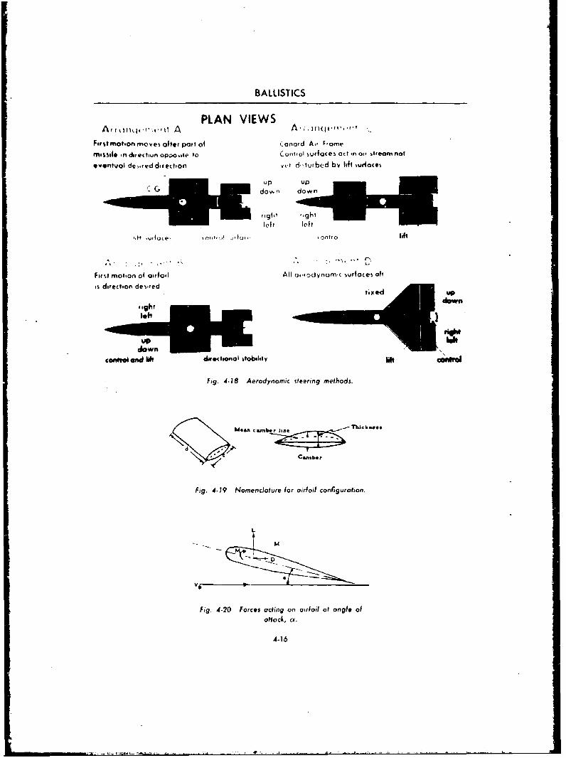
BALLISTICS
PLAN VIEWSA ttkin o -q,' to, f A A ;- ]w (jw. .....'f
Firstmotion moves ofter poart ol Canard Ar Famemissile in direchun oppo~te to Cont,oi surfaces act in ai, stfeom not
eventuol de,,weddifection vYe di~turbed by lift %ur4oces
dow, n dow
right
left left
,,f t ,v rfi o e , O n tr, I .n t o lift
Firt motion of airfoil All arrodynamic wurfoces aft
is direction de% ,red t U
right doww n
UUPdown-
caon" Mwd Mt diirctiional stablity
Fig. 4-18 Aerodynamic steering methods.
er lin
Fig. 4-19 Nomenclature for airfoil configuration.
L
Fig. 4-20 Forces ading on airfoil ao angle of
attoc/, a.
4-16
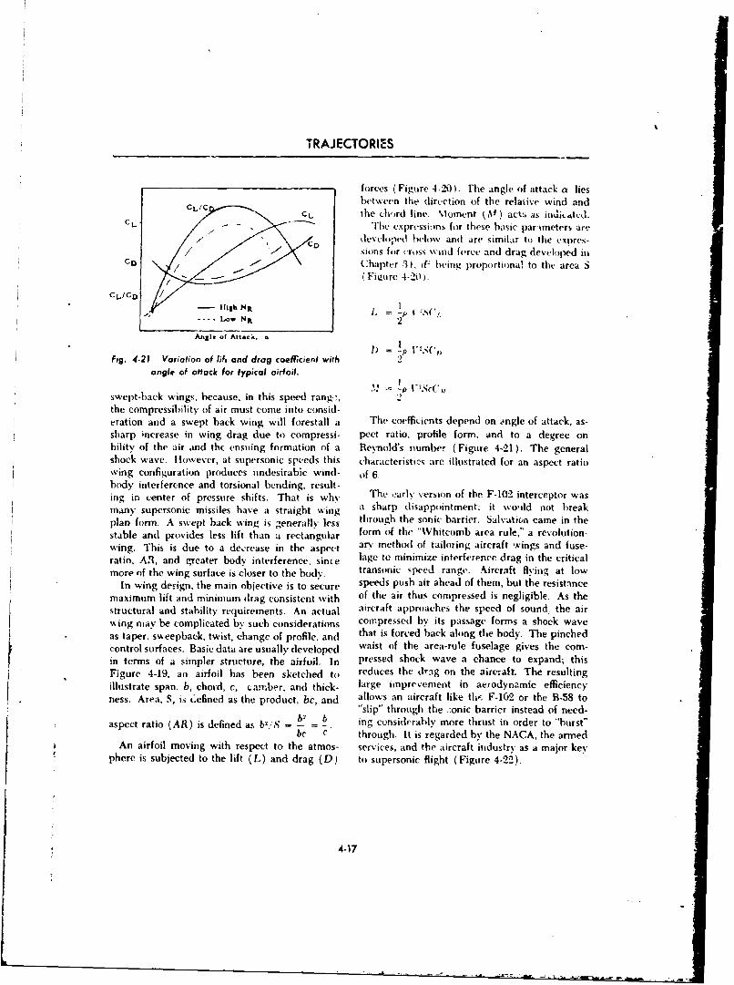
TRAJECTORIES
forces (Figure 4-20). rhe angle of attack a liesbetween the direction of the relaiive wind and
CCC L the ch'ird line- Moment kM ) actt, as il1%i4~k.4tUCL"/ -------
The expressions for these basic parameters are
.D devehloped bhlow and are similar to the expres-sions for ,ross wind force and drag developed in
cl- Chapter 3 ). (V being proportiona! to the area SSFieure 4-20).
CI.,/CDHigh
Nit
Anglei of Attack,. a I)
Fig. 4-21 Variation of lif, and drag coefficienf with 2angle of attack for typical airfoil.
swept-back wings, because, in this speed rang.:, .the compressibility of air must come into consid-eration and a swept back wing will forestall a The coeffii•ents depend on angle of attack, as-sharp increase in wing drag due to compressi- pect ratio, profile form, and to a degree onbility of the air and the ensuing formation of a Revnold's number (Figure 4-21). The generalshock wave. However, at supersonic speeds this characteristics are illustrated for an aspect ratiowing configuration produces undesirabie wind- of 6.body interfere-nce and torsional bending, result-ing in center of pressure shifts. That is why The ,arly version of the F-102 interceptor wasmany supersonic missiles have a straight wing it sharp disappointment: it would not breakplan form. A swept back wing is generally less through the sonic barrier. Salvation came in thestable and provides less lift than a rectangular form of the "Whitcomb area rule," a revolution-wing. This is due to a dec'rease in the aspect an method of tailoring aircraft wings and fuse-ratio. AfR, and greater body interference, since lage to minimize interference drag in the criticalmore of the wing surface is closer to the body. transonic speed range Aircraft flying at low
In wing design, the main objective is to secure speeds push air ahead of them, but the resistancemaximum lift and minimum drag consistent with of the air thus compressed is negligible. As thestructural and stability requirements. An actual aircraft approaches the speed of sound the airwing may be complicated by such considerations compressed by its passage forms a shock waveas taper, sweepback, twist, change of profile, and that is forced back along the body. The pinchedcontrol surfaces. Basic data are usually developed waist of the area-rule fuselage gives the com-in terms of a simpler structure, the airfoil. In pressed shock wave a chance to expand; thisFigure 4-19, in airfoil has been sketched to reduces the dr~ag an the aircr.aft. The resulting
illustrate span. b, chord, c, camber, and thick- large imnprevement in aerodynamic efficiencyness. Area, S, is defined as the product, bc, and allows an aircraft like the. F-162 or the B-58 to
"slip" through the .;onic barrier instead of need-
aspect ratio (AR) is defined as b?;,S = - =_-. ing considerably more thrust in order to "burst"bc C through. it is regarded by the NACA, the armed
An airfoil moving with respect to the atmos- services, and the aircraft industry as a major keyphere is subjected to the lift (L) and drag (D) to supersonic flight (Figure 4-22).
4-17
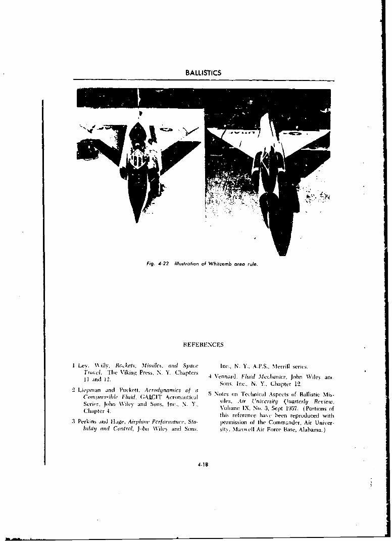
BALLISTICS
IL
Fig. 4-22 Illustration of Whitcomb area rule.
REFERENCES
I Ley. \Viily, R6-.kets, Missiles, and Space Inc., N. Y.. A.P.S., Merrill series.Trntel, The Viking Press, N. Y. Chapters 4 Vennard. Fluid Mechanics, John Wilev an.I1 and 12. 4Vna,.FudMcais on\ie,'at
Sons. Inc., N. Y., Chapter 12.2 Liepman and Ptuckett, Aerodynamics of a 5 Notes cn Technical Aspects of Ballistic Mis-
Coi•prces.ibhc Fluid, CALCIT Avronautical s5Nes, Air Unicvrsity Quartcrly Review,Series. John \Viley and Sons. Inc., N. Y.. sls i 'iest urel eiwChapter 4. Volume IX, No. 3, Sept 1957. (Portions ofthis reference havc been reproduced with
3 Perkins and Ilage, Airplane Performance. Sta- permission of the Commander, Air Univer-bility and Control, John \Viley and Sons. sit,, Maxwell Air Force Base, Alabama.)
4-18
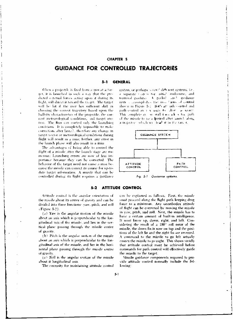
CHAPTER 5
GUIDANCE FOR CONTROLLED TRAJECTORIES
5-1 GENERAL
I ht-n a proit',tit is fi rd fi,ln aI i at a tar- systeIii. or p{rhaps , %tr;ý' dill- rent sstems, i.e...ct. it is latinched tin stch a wa, that the pre- it separate , ,t( u for iuilhji nmid(ourse, anddictcd caodrnal fort-cs K ,tiiu. upon It duriLZ its terminial ucnrdan,. A -,i,hI' l, iss, 1 u'dance
%ii. . will dirct it to\h ard the 1a. t,.t. lThe target sisSt :.•.ceo i t;uAIAot ' 1 'W,, irm, if nritrol% iil 6, lit if the user has sufficient skill in shov n ii Fihiur, 5- B::(• at' ideh, ),i tr)l anid
clie.iing the irrect'l traj.etory hased upon the path cntrol in i :,a.. I, &. - , rac"hallistie" cha;acteristics, of lihe projectile, tihe cur- This 'oulplete s .1i %ill (At e-, % I:,i ;)athrent nleteor, h,..cical c,,nditionrs. ;nd target mi - ,f tr. miss.,e ht, . . lt, i is'd ifter "uine. .alnortioim. The firer catn contrl only the ]iinlchicltfg a traject,,i, %.d.h h %.'i i!ea" r :0 t: ,- 1a,. -t.ctoiitons. It is -oropheteix impossible to makeccorrr.ect ,in after lallr,_r. . thi-refore any chan.c in Itari¢'t Xeetl r or mcttuorolonicaI condlitions during GUi;.,,E SYSTEM
flight 's ill result tit a miss; further. anv error in Lthe launch phase will also result in ai miss..
The •d'i nhtigis of bwin0L aile to control theflight of a missile after the launich stage are nu-intcrolls: Launching errors are no% oif less im-portance because they can he corrected. Thebehavior of thc target need not cause a miss he- ATTITUDE PA H
cause the missile (-an correct its course for up-to- CONTROL CON~qOL
date target information. A missile that can hecontrolled dtrir,.i its fli a Fig. 5-1 Guidance systems.
5-2 ATTITUDE CONTROL
Attitude control is the aounolar orie•itatuion if cmahe explained as follows. Fist. thrt nissilethe missile about .its cente'r (if ira itý ,and an be miust pocced along the flight path keeping drag
divided into three functions- yaw, pitch, and roll force to) a minimum. Any unorthodox attitude
(Figure 5-2). of flight can be corroected by moving the missile
(a) Yaw is the angular motion of the missile in yaw, pitch, and roll. Next, the missile has to
about an axis which is p(,rpendicular to the Ion- have a -ertain amount of built-in intelligence.* ~It rilist knew up, down, right, and left. Coo-
gitudinal ixiss of the missile, and lies in tile \ver- Itni ko updwrghadlf.C .gicinal planeipssin throughthe missile a inther sidering the result of a 180W roll error of the
tical plane passing through the missile center missile, the down fin is now on top and the posi-of gravity. tions of the left fin and the right fin are reversed.
(bh Pitch is the angular motion of the missile A command to the missile to go left actually,bout an axis which is perpendicular to the Ion- causes the missile to go right. This shows vividly
gitudinal axis of the missile, and lies in the hori- that attitude control must be achieved before
zontal plane passing through the missile center commands for path control will effectively guideof gravity. the missile to the target.
(c' Roll is the angular ,,otion of the missile Missile guidance components required to pro-about it longitudinal axis. vide attitude control normally include the fol-
The recessity for maintaining attitude control lowing:
5-1
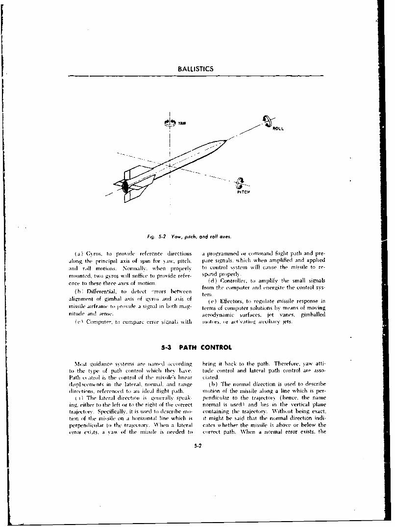
BALLISTICS
~IYAW %OLL
PITCIM
Fig. .5.2 Yaw, pitch, and roll axes.
(a) C~ ros. to provide reference directions as proygrammed or command flight path and pre-
along the principal axis of spin for %awv, pitch. pare signals. which when amnplified and appliedanil rol motions. Nra]-when properl%. to control systemn will cause the missile to re-mounted, two gyros %-ill suffice to provide refer- spo;nd properly.
ence to these three axes (if motion (d) Controller, to amplify the small signals
W Diferetia. todetct -ror beteen from the computer and energize the control sys-
aliznment of gimbal axis of gytros and axis of (e) Effectors, to regilate missile response inmissile airframec to pirovide a sigmal in both mag- terms of computer solutions by me.ins of movingnitude and 3ense. aerodynamic surfaces, jet vanes, gimballed
ec Computer, to comparc er-ror signals wfith motors, oir activatingt auxiliary jets.
5-3 PATH CONTROL
%14),t niuidance systems are nam.-k aiccordinig brngm it hack to the path. Therefore, yaw atti-to the t ' pe of path control which thev Kas e. tOule control and lateral path control are asso-Path c' atrol is the control of the mismile's linear ciated.lispL.icemcnt-is in the lateral, norinal, aind raInge (b ) The normal dlirection is used to describe
dlirections, referencd to an ideal flight path. motion of the missile along a line which is per-( i) The Lateral directionii is, t~envrally speak- pendicular to the trajectory' (hence, the name
ing. either to the left or to the right of the correct normal is used) and hie:- in the vertical planetrajectoryv. Specifically, it is used to dlescribe mu- containing the trajectory. Without being exact.tior, of the ini~sile on a horizontal line which is it might be said that the normal direction indi-perpendliceilar to the trajectory. Whlen a lateral cates whether the missile is above or below theerror exuts. at yaw (if the missile is needed to correct path. Wh1en a normal error exists, the
5-2
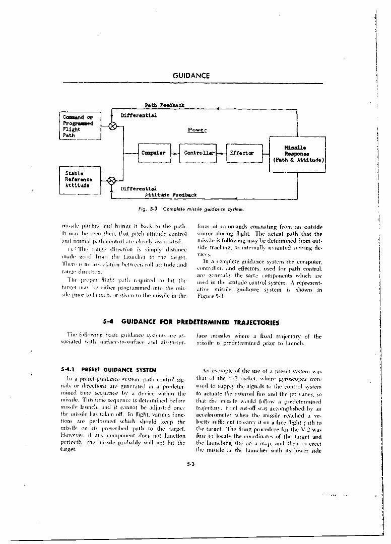
GUIDANCE
Ctmmande orDiferential1 __
Fligh 5- o plee ise gudr c ytm
c Th r;iiie diecton impleditnc side trcl Effetor inc-alsuaned snsinoe
Ra efdirenctiii
tar~t mas 'e either prorame Cnomplth s tie missile guid ance sytstemhow i
nis~ils pritrtoslaidubh ingr i t back to the pasil nthe fot~rm otvini-3.mnt fo n usd
ith fojl' iw b(. S I .ben' tj pitc d ance tnes conre l a s-oface mhirinfle ght The e a cfdtral ector ofa thesoniate paithi conrfe-ol airfe lnd- ai'-ito-ur- missle is predeteringa e determine too launch
5-4.1 PRESET GIDANCE SYSTEMAng or:il (ifthe use if waunpreset sn dysem-a1Init a~o p reoe tzhhne 'xstem, path Icontarnvsg hto h '2rckt hr so pswrnals~~~~~~~ ort Iictusae eeae n a crdtr- iu o msiplethe guiganalsysto m he conrol sVitr,
mie tim asesuciainc beta cei e rol tithud te toataeteandenlfisadteje aesmissle. histimesequnceis dtermuiebeore thator the mis ffectosused follw r padtheonroin,
the issie hs taen of. n flghtvarousarnc a clromeerai when thei, cmpssient rea chd are-tion preoper formedh which rhoulrd toehp the oi-t-d sficiten atoiud conrrv ton syfree. Aightesenth-t
missileon m%1 eitshpecrie pr rathie ito the trget. "the targt. Te fuiring e poctrem isr the w in2~saHoweverir, if aitinh componen tdoe nte fm nctioe n th rs F i lirae th5-3dnte.fth age
Therfcc lv. in themisie probable ~s'sei not b is- th ate amoisgsites oher a fixe. ad thaetn- of; tertargaet. thet mufc-orraeon iti5i- issile as prdthcrlin hed rwith its lowrc sid
5-41 REET UIAN E SSTM n v 'npe f te se(ifa reet ysemw3In i prset gudane u~stv .pth cntr. sg- tat f te -.-2 ockt, Nier g~oscowswe1
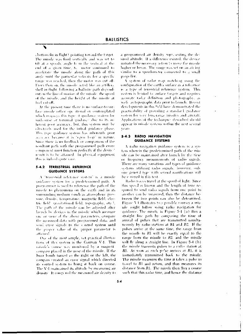
BALLISTICS________________
liittoiiiirill In flii.jht) poiniting, tim~avd the rgt it prigrainitied alir tlt'iiit% rep-, cnltini,-_ tile tii-
hIlke ilissile %% i% fired % irtit aill aindi~o as %v Ie (,o sired altitude. It at liffcreiici u~istuiI thet devNitetilt at a p o s'it. xiý-,,Iici It Ili :lot- xirtit al at the illitiaItedL tilet'lit&'xsli\ Itlil i tl '0 ainoe t filt' Oljixill
vizl of ;a tVts vil tinlti, to. not ittIr ( OItill Ilinv to 1 jivh r or loix-, r. lilt I iaiig %% as iet oiii l ; Ill Iit !
acutelirat tilt misil'ie alo)iic tile path o f tI is similLir to at specdiiini ter onietiecti to a smIlIJawlide unitil tile partitnilr \ elot it\ for Ispcot lfie p:oIiwllvr.rAnge \ 's I cit lwdi tutul the ilitn'i \% 1ot kit . A xs\stein of iaillir nip tittcintg, usi g, t Iti-I-r, i tIilir in. (lit insi-- ittt-d like Ii trtillcr, illlfigllratieli tif tue tclrtlls oslitfa~c ts a refi,i'iitt'11('!l ill flolgt. fl.~\intq i a ha ii~fItit path d1cpcild- I, a tN pc of terrestrial retervntce sosttti_ 1liii
vilt ,' theI liti- hil f Ino[iollIle if tH Illissili. tilh1e d Nolu s tein i., limitted ti , Iirlat.iu t.wirgtNt and ruijlirci-, It tIl it iis'lot i's I .111 mi t-e lIt(-l-it tof 1 Ite lllijxiltl at .i, ItIiiAt, rail,it- ilt-fmntioniii n1(] ph totgraphl asI I It ii t-iif. \%ttl1 als tiipii)gr.i I i tI %(It.II pr I lIr to( i Ini-ht II . I I etI I (-IIt
\% lli.thi 11.1 tilt, toiiicýtk _orda ui'nir iif ýtiti GUIANC SYSTEMSr(. ni n ,rral
midi, -i-l w iiit v f ininai t-i pere lyif toe itesir- thuli ss-iieA tilt- rt'dternuitilelt,4No pat ilof th( mixisilta5t 1)l~ir Iltt,iti N. liti this s% ti{i lllIt'l milt )w,~ hperin Ikiiuiuttt N ft\ hauN%\W nt tit [i(t sc tlc tua:ttis ,! ix d forhlu qitioit miir fruipienush Cuanen-t ofl~x' lalii sisnl
Sil(( ire are) I(I)LI Illr (of th atDAC iiHSYSTEtMpS gl dnt
GUIDANCEtp!'l %thli( SYSTEMSlnle iath ctail A nidtop'- i ithtiin raldrniioifieatiois Istihi
t-\p tiin' ni-srii iun-ieroie s st-t-t\ i.f the missile ltin ( iercin this tredt.rnnz ~t ftcms
[-ill i xte'n b r attlid puIiiiiii phosta ~ ltpleli . 1\ hCtiji IW .uits traxe iltL- tle speed b oflight. Snt
[ili~rt~iiirsawti i rfertit th 1iit11o tliu' aire pid it\ kNn art ind tit nt(Igthc o:f tIIide rt'I5-4.2llu TiRETRA REFeiiRENCin liitl uttatiiiis 'i I't ti lith. I raditou si.iuiils fIlmvc, oiiC nlilt i
xiirtiiiiii uietlllil ~ t itia lhuis)I mi'rit e be(\re d~ .iiti i ealtheillsit teis t ueditacehe\il stcrixit i for a pert to treinai it I paethI. eA Radi \%tae tli traI vI at iftS cal isi e d t ei ]it Si ntd
trie field o il ttiii fiId to~po-xrirh\ii etc. I. Fiotirl, 5-4 ihlltmiatt't tuko pqsuhue c-irsts at unis-'itue j'atl if tiut :iisxiii can lie adjiixtt'd after silt' ituiglt follow using radio navigatioin for
iAIii11li I)\ d-.AiCe ill theiit'~ Muic-h nuecisurt' Liitiancu'. Thit missile in Figure 5-4 ý.a) flits a
liio or :wwi ) f thtil-)%(,i pa.linictttrx C ouupart' straight line path buv .:ompIrinir the tinle ofthev Iiiiaxtiurt data ss ifh prieraiwinedi dalta. alhil arrival of pulses !hmt are transmitted simuita-
Wlii urriir Nuiink to tile iinitroi st~steniulintil rticousls bv radioi statii~ns at RI and! R2. If thethit- pH pcr \Ji oii f tile p roper pa ranwiit er is; pillkes arrivse at dicu same time, tue ranige from
ati~i i Ii 1tili muissile to R1 wtill be exat]ti, e'qual to tue'i- f t0)inv s simplte. s tt prac~tical ilhiistra- range. fromt the missile ttu R2. and tie missile
tion ofi itt rs sis shin is theu Ct'rman VA. This will fly along at "raight line. In Figuire 5-4 (b)
Ilk-l,- .1,11 55.'.iolllit'iitt li% it magn-ti tiet fliiN.silv trilisuuits ulseits to a I idjo station atillt15pliat-A ill tienolse of the' mlissile, If the RI. As soon as each p''sc arrives at RI, it is
huit hiindu turned ilo the righit or the left, tile inlrlidiaitel\ transmitted back to the missile.ucompass , rcatti .li inriir %ig,-nal Mikhli~ direcetd The missile nicastlres the time it takes at poise toit, tiniutrii xs xsttni tou brin-, it hack oin course. tuasci to Ri ansd rctiurn, and thuns measurtes itsVwi' V- I mantainedilit its altittude.I~ rismaqui-nilu air distaillte from R1. The missile then iflies a course'ii sits.. It (I rt p.-rid tht fea ic.suret! air de.-isits t ii xiicli thiat t his radioi time, anrd Ilenix the distance
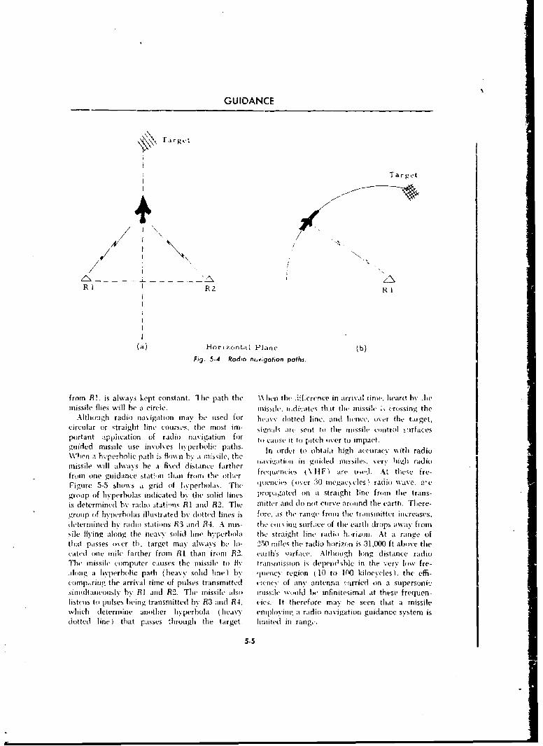
GUIDANCE
rTa rge
Target
Z1NR I R R2
(a) Horizontal Plane (b)
Fig. .5-4 Radio novigaton paths.
from R!, is always kept constant. The path thet 1 \ieni tlic 'if.crtence in arrival time. heard by AIimissile flies will he it circle. mnissile. ldiýdkates thait t~le missile ., crossing the
Alt hou gh radio) na igat innn may e tised for heavy (lotted line. and hence, over the target,circu~lar or straight line cour-ses, the most imn- signals arc sent to the mnissile control s afacesportant -tpplication of radio navigaition for to valise it to pitch over to impact.guided missile use involves hyperbolic paths. In order to obtaja high accuracy with radioWhien a li'.perbol ic path is qflown b,, ar missile, the g
missile will aiwass he a fixed distance farther . $ i( i(,I cC n sle.vrhil ad)from one guidance station thani front the other. fre 1 Iiencics 117 a I re owl. A, thewe fre-
Figure 5-5 showNs a grid (if 1. '%perholas. The quencies (over 30 megacycles. radio Wvave. a'e
group (of hyperbolas indicated byý the solid lines prop~agated on at straight line fromi the trans-
is determined by radio stations RI and R2. The mitter and do not curve around the earth. There-group of hyperbolas illustrated by dotted lines is fore, ais the ranq~e froin the tranlsmfitter increases,deter mined by radio stations R.3 andI R4. A mis- thle c1' iv inm.ý surfalce of the earth drops away fromsile fliying along the neavy solid line l.perbola the straight line- radio ho rizon. At at range ofthat passes over th- target may alwvays he. Io- 250) mjiles the radio horizon is 31,000 ft above the(-atell one iuile farther froin R 1 thatn i rorn R2. earth's suirface. Althoug~h long distance radioThle missile computer causes the moissile to flv transwission is (elepe(I-ible in the very low fre-,loiz itg a wmperholie path (heavv solid line) by quene; region (10 to P00 kiloeveles), the effi-compotring the arrival time of pulses transmitted cienec of an\, autcnrma raj-ried on a supersonic_simuitlt aneously by RI and R2. The missile, also mnissile wou)lld Ihe infinitesimal at these frequen-listens to puIlses being transmitted by R3 and R4. cies. It therefore may he seen that a missilewhich determnine another h~perbola ( heavy emplov'imm, at radio navigation guidance sy~stemi is(dotted line) that passes through the target. hlmited in rang,-.
5-5
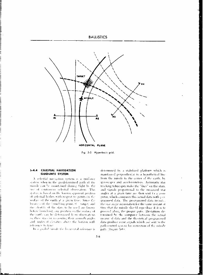
BALILISTICS
N,
'TARGET\
A A
at\\\ /
HORIZNTALPLAN
Fig. 5\ \yebi. rd
5-4.4 ~ CELETIA NAVGAIN Norie ) tblzdP~flMW)1GUDA CESSTM aitl-iidp-pcalcla t t ~p~lcicd m
(ch."tial ~ ~ ~ N"I"ii'lc r~ntum~il ( h ctr(fficr
\%icrin II(,pic ocr-im d p th 4 i(. ýýn ic:pcsand accleyn etr.A tm tcsami~il. 'i '(-Inlli~it- d ril"fll-d h\ E Ow Nr~kn Neecpsm k h(ntesas
'Nf Nhý an kn- -m otoit ~ b nam-ds
i.4.4 CELESt )fTIAL NAViGATION a ,1(m! m th'tr it tld h issa stbwilzd platformc wif h is t
Il t-h~t,~ ii lmla tl\ 1atjoI 5V ten I ~~lj, f( e M frm tin nid l ti 4t he center ofii the earti . dv-~thucai t,, Iwfii tile mi ed Itrh i tit h ft- t--r~Tnedij)4 andt ace(imlert)I lwt the Auo at-ic tar
tO lt iii:,' jný I i~lir~iw-, tdurii 'Ilijit h 11CA1u t dckn dtals ~ mandth th rci t-e {ires In the stars
Im uvell )tIa hills 'tio ah respetlic hirizmit en tie potei pr, lijeh utnpaeis tak actual data , ie ti to tit-
rch ic ii.ii i44 ciI hlýio4 ti t- pa ic F t~r h (,a lo th fill- c Picltum atOl ( Iftt i-%~(iii art i ii Ii iiitri Iiiii i'tIiI 141- atel(I is ptr ;iie I I- i-ii ciIpli litw ej th-iet,

GUIDANCE
Prgramed
Automatic StarF Angle Data
StarTraeicare
Coq'ut~r Error S4 ipa IWith to Path Control
Stabilized Act~ualPlatforu Star Angle
fig. 5-6 Schematic of celestial noyigotiorr guidaric?..
Ili order to lhe ciflcctivc the svstcois muost he integrates it. andi determrines an error iignalableC to trock stars in the_ d.astimle as w ,l a rd'!ht. which is -sent to tllw, p.1tli Lontrol system ats a dii-This has been iceconiplished with ves ensitive tance off courst.. The control system of the mis-photoelectric cells. sile will react to thre error signal and move the
mnissile tIn; sane dlistance hack on course. The5-4.5 INERTIAL GUIDANCE SYSTEM .1cceleroroeters meanwhile detert this second
Ani laiertial guidance sx stern enables ik missile, acc'lcration, the -orupurer dobyitegrates it,to follow it preoletermined path by tile emph)I; ' - and when tHie missile gos back on course, noment of scns~tive aeccieromneters wvithin tlW umit ci ror signal exists. The missile then continuey on)iue whiich inAL, us,, of the principle of Newton's straight line fligirt until another error is intro.second law of ino;' ort, F = mai. An accelerometer ducecl.is a device which measures arcceltra~ions -with Accelerometers are also used for range control.reference to at stabilized platfo~nr. Gyroscopes As tile missile accelerates from zero velocity to
and accelerometers are utilizeri to keep this its crukintý speed, the accelerometer measures,abnlilized p~latformn perpendicuilar to a line from thle acculeration, andI the computer converts thethc missile to the center of the earth. In an acceleration to distance ocovered along the pathinertial guidance system., accelei-micters dietect of thie missile. 1\Xhen the missile reaches cruising,rceelerations hoth along the predetermined flight speed and the acceleration is zero, tl19 Computer
path and perpendicolar to it. This infonination comptit s distance ( overed on the ground byis furnished to a ucimpurter whici d tiily tinte- m ultiplv ing velocity times time. if the missilegr-ates tlie acecieration as a font-ti.in ot time and changes velocity along the path, an accelerationdeterinines distance, since or deceleration will be observed by the range
distnceS f a (i chaccelerometer and the computer will determinedistnceS £Pr d didistance by doubly integrating this signal. WNhen
If a missile is launched on a course toward a the proprer range has beten covercd, as pro-target, it Will remain on this course until acted gramnme(] 'Into the missile prior .o launch, theOn b-, an outside force. When this outside torce computer sends a signal to the control 3Nvster-i to(suchr as a gus:. of wind ) acts to change the dive th2 missile into the target (Figure 5-7).course of the missile, an acceleration will be ex- Although relatively simple in concept, the die.perienced by the missile. T1ie accelerometer ve'opment of an operational inertial ,. 'iidance%.'ithin the missile will detect thi., acceleration. system presents many problems in order wo attainThis signal is sent to a computer which doubly required accuracy. Some of the most serious
5-7

BALLI STICS
FlightPath
PlatformAzmt
op rror~ SignalsA CCWARERTo Control Syvi.
Accelerometer4( Range Accelerstiorm 3ignal
Fig. 5-7 Schematic of inertial 3i;dconce system.
prohiemrs arv: gimbals produces torques. whichi cause the gyro-
(it A missile in flight is subjected to ceri- scopes to precess causing deviations in thletrifugal force due to rotation of the earth as well stabilized platform. The magnitudes of these
as tile for(ce of gravitv'. This makes it difficult in teviatiijils are not aliwass predictable.
attaining it true vertic.al for the stabilized plat- Ani ertia gro isan c ye ofs'~ q 11~aS obform. ilitl sn seo uidaonce f-ar long-range
mnissiles It is part'cilarly Nell suitod for long-(1)1 A missile in fih is subjecit-d to a d: ognie ballistie t,,pc znijsiles since tiei time of the
torting force reSulltitqg fromn rotation ~)f the earth glui ded portion of the flight is quite short. Thecalledi Coriol]is force, ace! 11011latio n of ernri a x.w the refore bI er
(c) Friction in the hearings of the( gyroscope slight.
5-5 GUIDANCE FOR CHANGING TRAJECTORWS
The fol loss in ggoitdilice S% SICHI S are associ teýd silt, is laonel ed tow iw-rd t he general h icat noti of at
with surface-to-air. air-to-air, L'ntl sholrl-riing( ininixi g target aiiii is goi tied to cointact )r closesi rface-t -surfa~e mnissile s%'steins 'sher,- tl- inis- proxiim t% to an evasise tairget for at kill
5.5.1 COMMAND G1JIDANCE SYSTVj ~ llsint int) tihe comtpiter.
A "command s~steoi" is at g id anee conat rolI Oeo i u isthsi ip~lc CSti ~syý_cm wh-lereini thle path iiif t he miss ile c-an 1be pa- iblem is thli systemn use d t o gide it d r 'n
chlanged after Iao n cl h~v dirt-ct ng s igi a s frio-n p)flan- into at tai rgt. A lium an opera tor i A seris 's',Ine a'_ 'incl. outtside the mlissile. Information ais the iriln~i aind th0 target, estiiflatf-s the Jlaiigestoi the relatie'' position of the ta'',,et anti ti' inisi- ri-qoiiri'd in t~w 'lroý,,*s ~iight palth, jifll sends
sil isfurishd t a ompter( nthe gronothd 5.8 iJa signals to, thiedrone whiich.thirouighi
th A71gi't. Thie riiissile ss-ill fillo% lln intercept Io-air svst' iii, tie huiiran operator is replact'd his
Lrjco.dt-iic F-twnvgto~lrw!od torolr n tcrptr(iuc58 n-
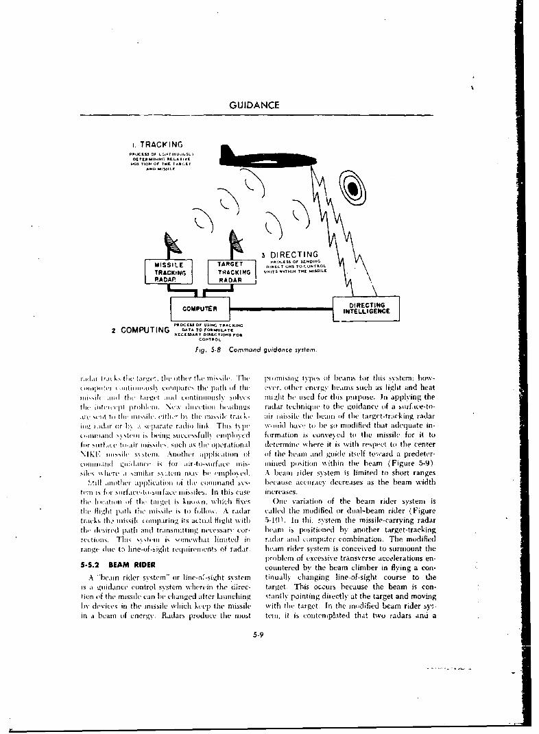
GUIDANCE
I. TRACKINGppOCEss ot ON rINIJUUSL1
OCtERUI.ING REAIJYLt1,VSITION OF THE T*ARGET
AND -53ILt
S~tCENAAN DIRICICTSINO
MISSILE COTARGEOLN T o O
fi. -Comman TRACKINGe sys WTHNTHEm.
S1EI(IPAA RADARh ace. ielt~ i ussh h imlssgtps(fIersfo hssse:bwIII~I II L lit I(Ill (((ii uirs tu pah 1 f te eer.otisr eerg hems uch s lght"ndheaIII I( 11(1t I tt~rg t 111 II1stil 11 s! S ive 11 gs e sedfu t u DpRpoE.CTINpG ig htiltCMPTE INeljtp~ill] Nw(iLtlll~ics rdrtciiic o TlEuIGENCE o ufc-o
N 1 I.Iliss I ~ ttJ) AII Fi g.I 5 -8jl~til C ofmn qiOf t e syse m. n ud isl o ad rdtr
)AIM Ito.111 k il thei ntat fit, fI r ar -t~l-SI I rfssce iisis- i isined , (%u Ii on WitI i , in r t hie bem ysFguem ho-9
soitswit-i I.,a u-,iusl (.oAtnpac tsli pat npof eti( Abm ohridenrg bseams isuc limte toishot rangest
l~iill '111d IthltI :11)!i.cit ll] 11 thet eoinaIndls\ sovs- because b( acusdfrac deceis aupste. beamplwidgthettl ic IfrI,4l p~rfl~ cm t NI- -lr .%c (isu ciosls n t1is ad lse ilreadasech iuSoteg iaceo tr~c-
.tilt %I(-tt ton tfthe targetlc c ish- kImI t 15. misslel tracks ai nsie thriatii in of the beamridetracsystema is
tlle Iigit~i ort 1),die separate rais o flink Tk A radar called thev-t es modified ora dulb amrdequa(Figurtraks im isies Iclopring it5 cssfulk formattl 51.ion ihs costeme o the missile-arrying rada
lie dsin-hd poatr In i taS1 ni Uitt in 01 necesar t ir- beeamns i here itilioodibh another tartet-rceinge
rcilltl- I'll t Ill t 54511 isfo air-ft\5hsit lfced inis rnndr aositio mnp tcrn com bination. gTh e modi9)erange No.iue it lineo-iga t requirem~kv ent of radar,. beam rider sNystem is cocimied to suormut thnes
!Ail antlii aplictio oith ommnd pro-blemoa ecesie tcuac ereanserse actelberat ionsen
.4 i beam rtidrfa osistem' o ine--sits In atgis linao-sgh courseatoet-tha gli(lato flecnrlssmwhei the drc target. Tis Wo%,wiA i n aitocnr becus the beam iiersstecons
tII(- lIfithe miasil cand bercansitngd aft-er launhin btanis posintiongd diety atother target-tandmoingby evices. Tin th iss.ile soicwlheepth missile i it tadar targcopuet. cobnnin t he modified ba ie y
inabamoinero-sgy. Rdrs piroduenthe muf taa. ba ier, it sr is contcipaedithd two sradosunt ahran c (it t-prole ofexessve ra sveseacceleat5-9en
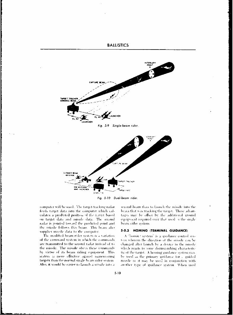
BALLISTICS
CL ft
CL AZLAUWC-HER
Fig. .5-9 Single-beam rider.
D
Fig 5-0 Do-eom rdr
oil trget ata indl inissil(- data. TI it. wo. oii -uti n rnit- tlrt 'i lc A tj-silIraa i iw~ tard Iit'w pred leted po(int andI beaiti ridier ss stein.
th`Msiefo110%%s tlliýb.%11 1-~~r his ht'air alsoda1Sit (.i.1 to tire c fllli)IINti. 5-5.3 HO IG(TERMINAL GUIDANCE)
'imdfclbearn rider ssstirr is .4 NariLtiorr k iron s steinj is a'rIirirt t(iitrir s sof the ttoimnaird ,%stein in wtiicii tiht e-innlhiandts iut'l ss ervinl tho thirt-titon of tit( inwilossik '~oheare transmitted to irthe secrinr radar jinsteadt of too thiuired after 1,itincir hv i device. in) tlit nmissilt.the missile. 71-i1 Missile idtvS theSe' c-1nliut(Is wbthici realcts to ;oe lStiiituiishill., (iar.rrtt-ris-hv virttoc of its iwain ridingL t(ýiipiInint, Tlijs tic- of the target A loomoing i.uiidaincr ssstern uia%'S~stcrrr is Iinorv effective igaijiot rranireti~urini.ý 1w uitid as the, primiary mizuidavtt for .- gi.iiitd(itargets titan tire normnal sinjI ~lw am rider sostemt. nijssile (ir it iaN ire itstQ. in ci in rinetir n witliiAlso, it wotild he- easier ito launhitri a irisile iritui a .-n'inthir t\Irt (ifl r4iidarilwa trn Xhr rIseti]
5-10
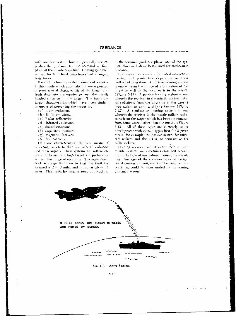
GUIDANCE
Nvith another systemn, homing. generalls .iccom- to the terminail guidance pihase, onei of the sys-puishes the Lguidance for the tPrminal or final telas discussed abose heing used for mid-coursephase (if thme missile trajectory. Homing guidance gunidance.is used for hoth fixed trajectories and] changing H omin g %ýstnrus can he subiv)1ided into active,traic itories. passixe, and unii-acetive depending onl their
Basically', a homning systemn consists of a seeker rietlhud of operation.i An active homing systemin thme missile whichi automatically keeps piointed is one Mi.rein tire source of illuminlation (if thleat some special characteristic of the target. and targ'-t as well as the receiver is in thme missilefeeds data into J computer to keep the missik ( Figure .5-11 ).A passive F amning system is iinlCheaded so as to hit thme tar 'get. The important wherein tile receiver in the missile ittilizes nato-target characteristics which base heen studied ral radiations from the target as in tile case ofas means (if percei'ing the target are. heat radIiations from a ship or factory. ( Figure
ia) Light emnissions. .3-12). A semi-active horning systemn is one
( 1) )a 7io emissions, wherein the receiver wi the inissile ntilizes radia-Ic) B adar reflectivity. tilins from the target which has bee!n illuminatedi (I 'nfrared emuissions. from somme source other than time missile tFigureý
(e) Sound emissions. 5-13)_ All of these types are- cuirrently undier(f) Capacitive features. dlevelopment withi certain types best for a given
(g) Magnetic features. target; for example. the passive systemi for infra-(h ) Radioactivity. red seekers and the active or semi-active for
Of these characteristics, the best mneans (of radar seekers.dIt ecting, tariets to (late are infrared radiation Homing seekers used in antiaircraft ort anti-and radar signals. These systems are suffciently missile systemns are somnetimles classified accord-dc-curate to assure a high target kill probability ing to the type (of navigatiomnal course, tie missilewithin their range of operation. The main draw- flies. Any ono iof the common t~pes (if naviga-back is range- limit ation in that tire limit for t iona I coo 1st*'5. pu1rsu it, co nstant bearing. or prol-
infrared is 2 to 3 miles and for radar abhout 10 por1tioinal. could he incorp~orated inito a homingmiles. This limits homingý, in some applications. 'tnuidance wsisem.
MISSILE SENDS OUT RADAR IMPULSES ZIWAND HOMES ON ECHOES l
Fig. 5-11 Aclo'e homing.
5-11
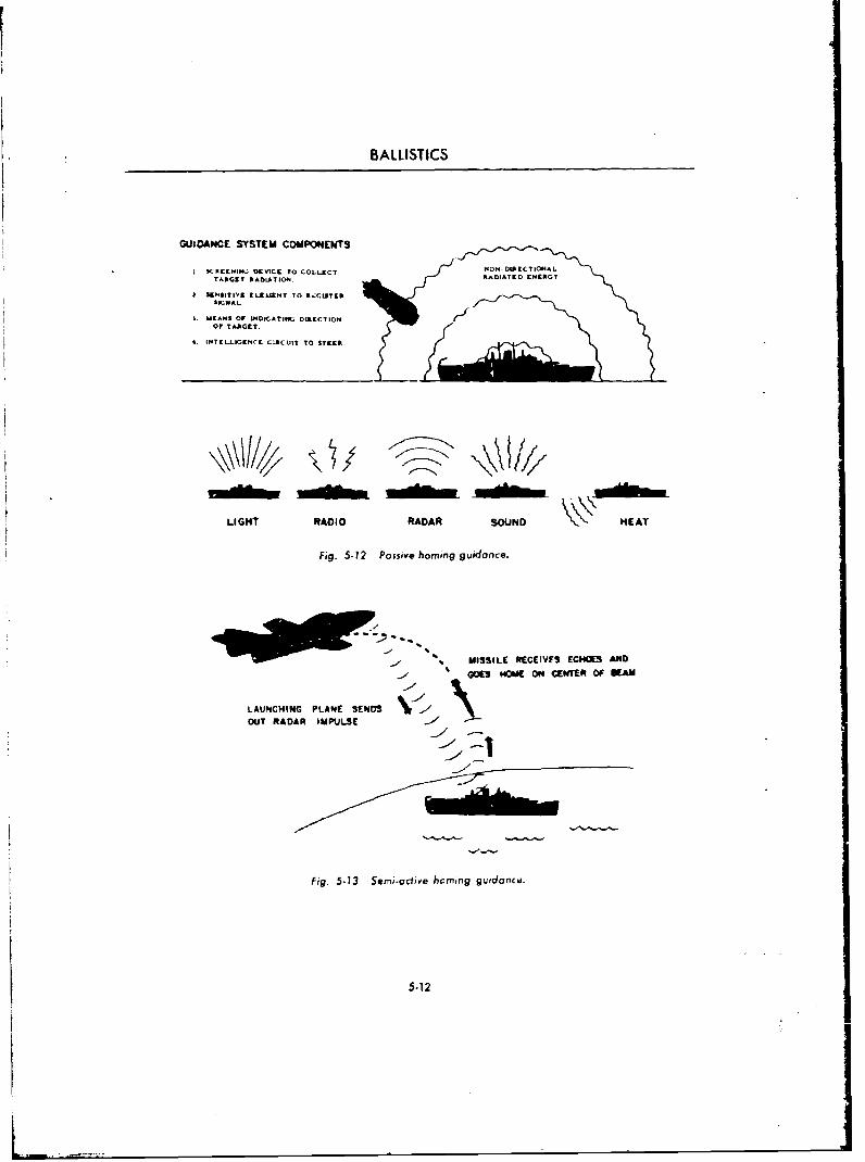
BALLISTICS
GUIDANCE SYSTEM COMPONENTS
I SAEEIi& DEVICE TO COLLECT MONOtM-DKrCCTIOi.LTARGET MADLATIOu4 Ik~.DIATED ENERGY
I SNSITIVE i ILUI.NT TO Rý.GUiTCRSICNAL.
J. MlEANS OF INOICATIG DIRECTION
OF TAAGET.
4. INTECLI.ENCE C:IACUIT TO STEER
LIGHT RADIO RADAR SOUND HEAT
Fig. 5.12 Passive homing guidance.
M ISSILE RECEIVFS ECHOES AND
LAUNCHING PLANE SENDS Nr/OUT RADAR IMPULSE - 3
Fig. 5-13 Semi-active homing guidance.
5-12
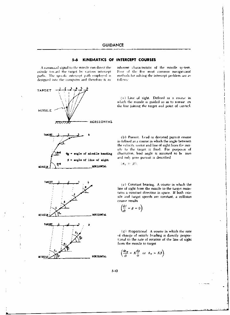
GUIDANCE
5-6 KINEMATICS OF INTERCEPT COURSES
A covnnaad signal to the missile can direct the inherent characteristic of the missile sy-tem.missile toward the target hb% various intercept Four of the five most common navigatianalpaths. The spcific intercept path employed is methods for solving the intercept problem are asdesigned into the computer and therefore is an tollows:
1 2. 3 4 5S 6TARGET
(a) Line of sight. Defined as a course inLwhich the missile is guided so as to remair on
M(e / line joining the target and point of contrcl.
HORIZONTAL
(b) Pursuit. Lead or deviated pursuit courseis defined as a course in which the angle betweenthe velocit. vector and line of sight from tho mis-sile to the target is fixed. For purposes of
eM "Is of missile beadinZ illustration, lead angle is assumed to bt zeroSand only pure pursuit is described10 angle of .line of" sight
A. HZONTAL
L-T . : .(c) Constant bearing. A course in which theline of sight from the missile to the target main-tains a constanit direction in space. If both inis-sile and target speeds are constant, a collisioncourse results
ia sm iz HM~IZONTAL
(d) Proportional- A course in which the rateof change of missile heading is directly propor-
,tonal t) the rate of rotation of the line of sightL 0, hfiom the missile to target
1 00 0 rý - = 03 or .,, -K
5-13
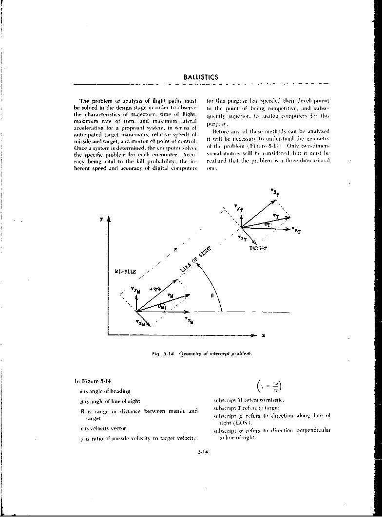
BALLISTICS
The problem of analysis of flight paths must for this iurpose has speeded their development
be solved in the design stage in order to obse-tr to the point of being competitive, anti subst-the characteristics of trajectory, time of flight. quentl\ sutr r. tto analog -omputers for thi,
maximum rate of turn, and masimum lateralacceleration for a proposed system, in terms of p frpose.
anticipated target maneuvers, relati\e speeds of efore an.Y of these methods ear, b. analyzedmissile and target, and motion of point of control, it will be neccssar to understand the gcometr\
Once a system is determined, the coiopputer solv'es f the problem Fi,•,mre 5-14 .nly two-dimen-
the specific problem for each encounter Accu- sitohal motion will hIe considered, hot it mIost h)e
racy being vital to the kill probability, the in- realzed that the problem is a threv-(dimr'nsioO.l
herent speed and accuracy of digital computers one.
-, "c~r - ",
I• T
T A~~
t ,
B is angle of l5ine Gofntrigof sntecipt p1robefestm msie
R is range om distance between missile and susrpt er ~a~taurget subscript /3 refers to+ direction .hon.5 line o)f
sight (LIOS ).vis velocity vector subscript a, refers tob direction perpendicular
"t, is ratio of missile vot to target velocity, to• line o~f sight.
5-14
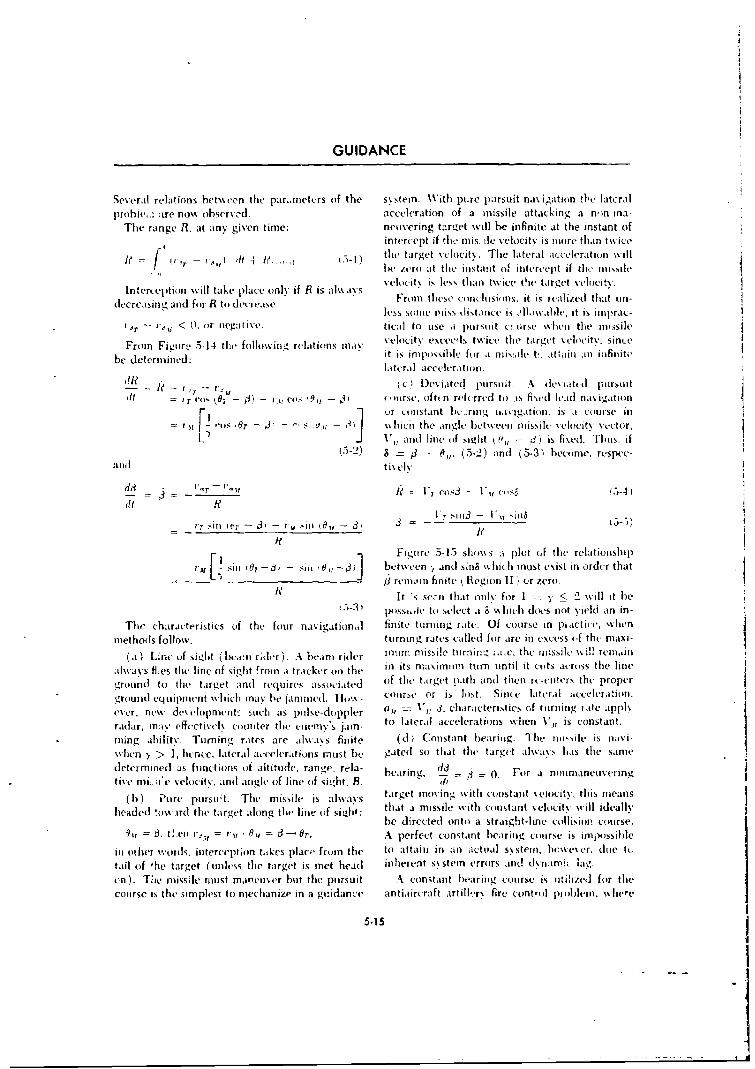
GUIDANCE
Several relations het%%veen the par~anetcrs of the systemn. With picre parsuit na~ igathin tlhc lateral
probie..: are now ohservc-d. acceleration of a missile attacking a n')n-ina-The range R,. at any given time: neuvering target will be infinite at the instant of
intercept if tloin is. ile veiocitN is more than t%%ice
f ~the target N elocity. The late'ral acceleration %kill
ft = p I - le /Aro at the instant of intercelit if tlir inusle
InteLCI~ion\%il tae plce nl% f Ris aays velocity is less thian twice the target V'elocity.intecepion illtak plae uiv i R s ~From these concilusioins. it is, realized thaLt on-
dlecrealsing and for R to de'creaSe VeOist tdiei oa ci siip~c
r. 7,_ -~ < I, or niegatIivse. tiwa to use a pu rsuiit ct. Iirse wh en tl e irn ssile
From Figtiri 5414 thle fojl~oiIiL relations inas' velocity exceeds twice the target velocitv, since
be determined: it is imipossibile for a nisile t.., attaini in infinitela teralI acceleration.
L I i,ý---c ) Des iatedl pursuit. Ade\ iatcd pursuitT I- ~j Jd - I': Voý '.91 jl I "rse. oftelan-rfcrred to is fi-ed lead na% igation
or cnstant bk :ring ii.i vigation. is a course ini ~-Or 3: ~ - sc hicii the angle between mnissile sciociAtv vector,J ý Vani'd line of sight ( 0,, 3 3) is fixed. 'Thus. if
a-nd S j - P, (5.2) and (5-3) become. respec-and tiselv
Vi- 1 S14)S3 - Vu ýzl
F. F! -e 5-15 shos a plot of the relationship
" ~ - -~ g rvim.lin finite R egion 11 '! r zero.
It ", se, n that oinly for 1 --- y' < 2 will it bet-) piisse,,je to select at & %%Inch doe-s not vield an in-
The characteristics of the four nasigationiJ finite turning rate. Of course in piactiic. when
methods follow, turning rates cailed for are in excess of thc maxi-
(a ', Line of Nidilt ( bceen r~ler). Abam ridler munm rnissile turnigrui'. the missile will reniiJn
Jky le thi line of sight 'roin a tracker on th5- in its nmaximumi tuirn until it cuts across the linegrou01nd tilte target and] requires associated of the target oath and then re-enter-s the proper
gt~lo~ eqipien ssiih ny b jmme. ,.~ course or is lost. Since lateral aceeaion,
ever, new deselopment- suchi as pulke-doppler al V1 , 3. characteristics of turning late appih
radar, may% effectiveix counter tile enemny' jai to lateral accelerations when 17, is constant.
rining ability. Turning rates are always finite ( d ý,Constant beariniz. Thu miiisiie is navi-w~hen y~ > 1, hence, lateral accelerations mnust hle gated so that the target alwik%' has the same
determined as functions of altitude, range, rela- he-iring di o. For a nonmaneuveting,tive miL ;i'e \velocity. and angle (if line of sight. B. Si
1) ) Pure pursoit. The mnissile is always targ~et mnosing with constant veioc:ity-, this means
headed (l-. .irdi the target along the line oif' s41: that a missile with constant velocity will ideallsbe directed onto) a straiigh-t-iine collision course.
9ii f t!e I ri I'~ it , t r A perfect constanit bearing course is impossible
iii other w.ords, interception tatkes place, froin the to attain in an autoal system., hieweer, due tu
tai (I hetaget (uinless the target is met head inhierent s~stem errors an(! dv(1%~ l
en). Tie muissile roust manieuv)er but the pursuit A constant hearing course is utdiiecl for thecourse is the simplest to mechanize in a guidance antiaiircraft artilieryN fire control probieli. where-
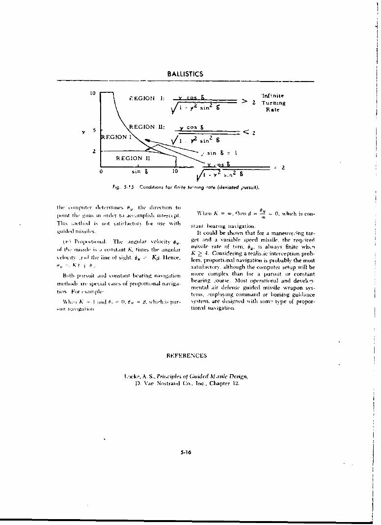
101________________________________________________B A LLIST ICS_______________ A LI T C
10 Inflnitei•EGION I: > o Turning
1-li sinRate
5 G!O REGION 11: y cos
1I Y2 sin2
REGION 1H
0 sin6 10 2 &
Fig. 5-15 Conditions for finite tu-ning rate (deyiated ,:ursuit).
the ftmputer dt.termines 8, the direction to W npoint the tuns in ,ifder to accomplisi iiteyrcept. \Vl'en K = •, then d = d 0, which is con-
This .ivth1od is not tati-factorv for use with staw bearing navigation.4idtjthd TllisSi1h(s It could be shown that for a maneuveing tar-
(. Propotrtional. The anvidar velocit' , get and a variable speed missile, the reqcired,f th, miisiht, is a constant K, times the angular missile rate of ttrn, 61. is always finite whenlocf t J tfshe iine of sighlt, , -K.. Is the angr K > 4. Considering a realis.ic interception prob-
uity Af ,,the jine of si.ght. e0,,= Kg. llen, lem, proportianal navigation is probably the most
, . ,satisfactory, although the computer setup will be
B1,th pursuit and constant hk'aring navigation more complex than for a pursuit or eon.tantmtlldsrt' S prp nai bearing courie. Most ttpvrational and develhp-
mental air defense guided missile weapon svs-tion ~tir tsarnple: terns, .rmpp!oving command or homing guidance
N\ 11':1 K =- I Mild 0., 0, 1 = is whieh is pur- systemn. are designed with som- type of propor-tuilt t1.1vigat i, i tional navigation.
REFERENCES
L'Kke, A. S., Prit.ciples ot (Guidcd M.ssile Design,1). Var Nostrand Co., Inc, Chapter 12.
5-16

CHAPTER 6
INTRODUCTION TO TERMINAL BALLISTICS
6-1 SCOPE
To rmIi~iain It,,iitIIi~t I( isi m . riotL oIt tI h jirm- ti i% pi . ~ . r r b iint 1.kI tAI 1, in ' V f actors i sciph-., tittirit %ini. thc uiii t, (i weaps On tar- v~sc tm ito iccoiiplkh thiý jpttst Tit( moist
I I ij\ituiai~ I c ,Iit.is ~it II( i- sj ct\ slIWi itTl tmI dW6111
~~o~i, . S ~~cit i-it \ ).., ov tivprfo rl n.ie i:s mi ll ilnceil b\III tid~liit \kt'altIJIt .11il .11 )]111 Iititiiil b1;1i- tOtsu ictors. wsith tltc exception of Iiiiing, r
ilill i irtlti tt-iTIItiJ (Iif('( I, iti Ili imar .thI .- llistitss ill 't hi, St., lon of the text.
6-2 DEVELOPMENT AND USE OF TERMINAL BALLISTICS
'II. Sitric.O ot t(riillintliiiliblistic, has Ligitzei store Oif technical data pertintent to terninoi~liiiidtit(. ('tipiiiittii~ stiticts((. of ,txt-riior andl 1,ilwilis. Mkich of thil diata, rcl.Lt~nQ t tit(th per-
intcriti ithidsl~t-s % riintl~rti\ h~t-, ist- of iliffic ill lcrttlt- of immuniitt~iton iii(i the silniirailtitv oftit-, ill otalttiilitit lit haic htt for Noinix . flapid targeos. has lwetti published Iin itide \ irict% of.to,.iiict'I, tiit- fit-h]i of raiol.itiphl\~t jitti litlih dLicoiillwts fotr tht- herlefit of both tit(, aeIIlnli-
sthix i.t it thu jipnttildu of s(kr-ctriic tll i,l %idta Ittittwnlltt unit perstlinui \%It,) tlaiiidt riltiiil, cilinps.v It-i e\xainplt tc-I (1 tit )b .tid i~rtct thi o1 pcittttf firepoxit-. Ili titi
frai~ilcttltionii thidhes \1!.(d~i Iins b\t % !It( h i-rs tr sItuf fit(ctr, tL tId tiit, propeir attmiiili-
ti'nl. Iliosittu. [i-sin dev(5iomtiJiiit% IdliJ(! tt imp-v- kilimti-iol-r's rcsponibiisi,ii to iii it properly.tInctiit, t is*rlt lotI~~jii 'In ;tiht. i t is h.it- 1 tha ttt illt iitpre~t.,mion tof the principles
* *t~~ppexar is institntancoi;.r tsentis to tht -hiiimin. ExIit,!nit,-, t: re toltl' liti-tr-rinvtt thethe ltime factor Iin terminail ballistic- imlest~gil proteipies cttvtiri.ýtiiic 111i1 1iiii-. s;:'V. 6Velo'it\y.
trins has~ often bet-nt thf- limitinilg f~ac~tur. ii.v lt~a adli Spaita i~i hstr;Lilitu to aisat Figlir'*ahilit. tfo p~hisicailk -orti tietatk'et ire-atils 6-1 resotitiitt fro tit ( L Ittttltifl iof tam-ti highi
Nss(h itaike p lace dirin, nt Iii e int ervals Of the -xid osi vi chia rg's V 1ri ;ir~- ito -ain K 'otwivedge
6-1
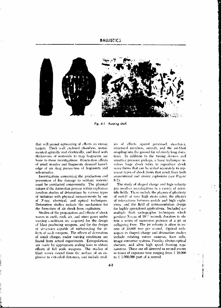
BALLIST:C3
Fig. 6-1 Bursting shelf.
that wi!l permit optimizing of effects onl enemy ics of effects against personnel, structurres,targets. Thick wall cnclosed chambers, iflstit- structural inembers, aircraft, and the air-blastmentc(I optically arnd electrically, and lined with coupling into the grouind for relatively long (lora-thicknesses of materials to trap fragments are tious. In addition to thle timing devices aridbasic to these investigat ions. Penetrationi effects sensitive pressure pickups, a bmasic techiniqueI i .n-of small missiles and fragments demand knowi- volvcs large shuock tuibes to reproduce shockedlge of air drag param'-ters c~f fragments and wave formns that can he scaled] accurately to rep-sub-missiles, resent types of shock fronts that result fromn both
Investigations concerni.mg the production and conventional and atomnic explosions (see Figorcprvninof fire (damage tomilitary mnateric: 6,)
must he conducted concurrently. The physical The study of shaped charge and] highi velocitynature of the detonation process within explosives jets involves inv esti gat ions in a varicZ% of scien-involves studies of detonations by various types tific fieldIs. These include the physics of plasticityof initiators with physical rilea,,urements by use of troetil at very high strain rates;, the physicsof X-ray, electrical, and optical tecThniqties. of interactions between mnetals and high esplo-Detonation studies includle the mechanism for sives; and thle fiehl of instrumentation designthe formation of air shock fronm explosions, for highly specCializedl applications. Included a,.(
Studies of tile propagation ari' effects of shock multiple flash radiographic techniques w,%hichwaves in earth, rock, air, and ot;ner gases under pioduce X-ramys of 10-' seconds, n(iration te. oh)-varying conditions arc required for the design tamn a series ef succe5sive pictures of a jet orcf blast produicing weapons, and for the Oesign collapsing P~ner. The jet v'elocity is often in ex-of stmrctichres capable of withstanding the ef- cess of 2ý3,(X)O feet per sce-oncf. Optical tech-fects of such wveapons. Tire effects of deonmation niques in shaped charge and detonation studiesof small charges under varying conditions are ir,clude rotating mirror cameras, Kerr cells,found from actual experiments. Extrapolations image convertor systcms, Faraday electro-opticalare tirade by appropriate scaling iaws to obtain shutters, and ultra high speed framing typecffects of full scale weapons. The studies of cameras. These are all directed to record eventsblast wasves extend from the surrfacc of an ex- in) terms of exposure time ranging frcmn 1 '10,000plosive to extioded distances, aind include stud- to 1 '1,000,000 part of a second.
6-2
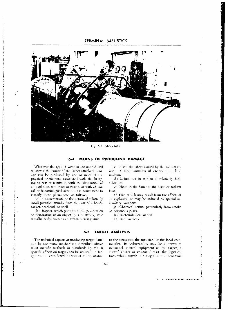
t TERMINAL BA' LISTICS
Fig. 6.2 Shock tube.
6-4 MEANS OF PRODUCING DAMAGE
Wdhatever the t, pc of w eapcon consltcreul and(I ( Blast. the( (flect exiised hby the sludden rv-whatever thf. nature oIf the ta1rget attacked, dain icasc (If lirgi' amiounts (if energv inI a fluidavge caii 1, produICed b% one or more of the med ion..ph- sical pihenomnena associated with the brin%!- id ) Debris. set ini moltioni at relatively highing to rcs, of a missilv, with the detonation of velocities.anl explosive, with nuclear fission, or with cht mi- e ) Heat, in the flame of the blast, or radiantcaul or i6acieriological action. It is coflven.;(nt to )!eat.
classify these phenomena as foliows: f iFire. which may result from the effects ofI)Fragmentation, or thie action of relatively all explosive, or max' be induced byspecial in
small particle,. exullv from tile case of a hbomb, cen,.:ary weapons.rocket, swariiead, or shell. k.g' Chemical action, particularly from smoke
(b) Impact. which pertainis to thle penectration or poisonous gases.or perforation oi an object In a relaitiveIv, hirge b Bhacteriological action.metallic bod\, such as an armor- piercin e shot. IRadioactivitv.
6-5 TARGET ANALYSIS
The technical aspects ot tirodtiiinsg target (lai- to the Stra~tegist, the tactician, or the local comn-* ~ "gv bN the man% mechanisnms (iescrlh ih os eV mand r- Its v.uloerahilitv may lie in terms of
must include mlethods5 or standlards iiý ),% hicl; peisonnel, euntro. eqluipment o- tile target, aspecific e~fccts on target,, can he realizedI A tar- -:intro1 center or Coi1ITIMnIV '),St. the logistical
- :' : nodý' I consi zlereýi in tcrrvý of 0,' inv, itancc lilies which slinno', U'" I irvet or the economic
6-"
BALLISTICS
potential whiich it sulipprts. LiLkevise. defensive tends far bemoi o. it coil ideration of the ttf"ctmeasures against attack at all levels pla) a ceiti- oif one round delivered against an eneyiv soldier-cal role. Target intelligence from the strategic Incapacitation of enemy troops requires wound
and( tactical levels miist inctlude details of target ballistic stý,diis which include vidnerabilitv of
vuine-rabilits. Vulnerabilitv studies of iriendly the human hody; effects of lbody armor; and
andI potentia II enemy' Weapons are highly scien- airi•ianent of friendly troops in terms of weightof principal weapon, weight of ammunition car-
tite processes: for example, aircraft vulnerability ried, s'eapon accuracy, training time requiredstudies indicate the best hope of kill against to reach prcficiency with the wearpon, and logis-enemy planes, and likewise, indicate the most tical iequirements. The optimizing of thesevolnerable areas of our own aircraft which can parameters may answer such proposals as theoften be minimized by redesign. Armor is evahl- arming of the infantryman -'it. an effort to giveaitd in terms of mobility, armor protection, main him a greater combat effectiveness) with a high%%eapon accuracy, and tactical employment. velocity rifle of small calibre which will be light,Basic data are concurrently fed into computers fire accurately at short ranges, and for which hefoi playing of mathematical war games. may curry twice or three times tie amount of
SinlilarlY, the problem of the human target ex- anmktiti,mn now prescribed.
6.6 PROBABILITY AND STATISTICAL TREATMENT OF BALLISTICS
6-6.1 INTRODUCTION bc, then it is said that the probability of c is aComputed trajectories for gun launched pro-a
jectiles, rockets, bombs, and missiles are based written
on a rigorous mathematical analysis; accurate bdata resulting from meticulously instrumented P(c) =-flight tests; and the overwhelming contribution For example, if. of 10 pencils. 3 are red (let theof electronic digital computers to solve the basic attribute red be denoted by R), 4 are blue (B),equations of motion. The user, however, re-qitires additional fire control data (range and 3 re green at thn tyideflection piobable error or dispersion data).The designer and the weapons analyst demand 3 P()performance in terms of hit and kill probability. 10iincluding all variations resulting from human or These data may he tabdiated thus:systems errors in handling and processing data tothe gun or I munching device. I"hc follow% ing is R R R B B B B G G G
. brief treatment of the mechanism by whiei, Obviously.
such information is evaluated and used. Thetotal problem is one of statistical analysis which P(R or B) 3 + 4 =7 P(R) + !'(B)is not only the basis for evaluating these per- 10forniance parameters, but is the basis for the ac-ceptanceThis is known as the Sut Rule. Further, the
ammunition and otheurimasse prodced Uite Stis probability of RI, B, or C is 1 (or a certainty);ammunition and other mass produced items un- whereas the P (yellow) -- 0 (imposble).der procurement, and in world-wide storage. Now, denote hard lead pencils by H and soft
6-.6.2 PROPASILIfY by S and retabulate:
If a possibhlities are each equally likely and if. H R P ,3 B B BG G G".f tie a, exa(tly 1, posst'. some miniqtme adTibuto, H If 5 1! S S ') H tt H
6-4
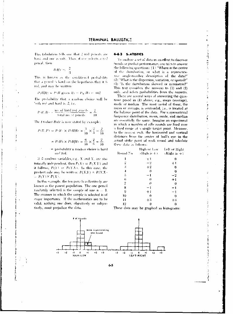
TERMINAL BALLISTICL
lhiis t almlatimn !.,AI wit- th. it- r'd I)( iw , tit- 6-6.3 S&ATISTICShalmil ,iJ oie i. stilt. hillis, t 4l" , i.'(t% t 1, A i a I set o.' data in ;ant effort to diseoer
penrj.il, tilul trenkd or predict pertormance. one tri.,s to answer2 the follohwio (fi.estions: ( I ) "Where is the center:3 4f tiht di itrihotiono or wh%.at is a represerntt-
"Thi, is kiw.en Iis thei c',ulti,d:i )lJ pi•)alilitv snitgh-ntmir:her descriptiotn of the data?"
thait .I pteil is Ihardl (iII the I~i~thi5 tihat it i l W(2 l i'What is the dispersion, variation, or spread?"reud, . ll( i IN bewrdilthten. h iht 3t Is the distribhution skewed or symmetric?"
Thins text c,,nsiders tit(h answers to (1) and (2)il = I ':l P , If g I'll, 7 only. and ii:fcrs probabilities from the answers.
There are several ways of answering the qu::s-I'he probahilite thi~t al rat il C:hi~().t' \iii b' tioni posed in (1) above; e.g., mean (average),)()tli red .ind hard is .2, i.e. mode or median The most useiui of these, the
mean or average, is centroidal, :.e., is located at,1,. 1 o lOhard r l ' thc balance point of tht- data. For a symmetrical
hI0 [it. ;)eI hltil.ils I10 frequencv distribution, mean, mode, and medianrli. 1 rodiit i ."(' is nw stated b\t xvl mphc are essentially the same. Imagine an experiment
"rU is in •hieh a number otf rifle rounds are fired over
3 2 : fixed r;nig at ,t single target point. Measure,J'Ifl.Th V IP,1 IN 1't111.,? = - X -lo 3 lo to the vta.,Lst i,nch, the horizontal and vertical
distances from tilef cenitir of bull's eye to the(IIi X I(I6IH) ( 2 actual strike poilt of each romnd and tabulate
10 0 t'est. diatat ;is follows:
prottabil 'y a raii(tool ehoice is hard Iligh or I.,,s left or Right(11,! red. I{Round ."u ii Igh is -4 1 lMight is +)
J 2 random v-ariables, e.i... X and Y, are sta- I -t I 0tisticaliv independent, then P1 X Pk X Y') and 2 2 + 1it follows, P( ) P( YA • 1i this cast., the :2 +2 0
prodtict rule maN Ibe writtu.n: P(X,.Y) =-. PlYXN 4 0 0P( Y . -I -2In this f".).aiple, the ten penn'Ils co llectively afre
"known as the parent population. The one pencil 8 - - 1"ran'onmh' sele:'Ied is the samp!e of size n = 1. I+1 -1
The manner in which the sample is selected is of i0 0 0.* major importance If the mathematics arc to be i lI--:+
valid, nothing one does, objectively or subjec- 12 0 0tively, must prejudice the data. These data may be graphed as histograms:
I of r, .. dSII
One round
; L .
- 3 .2 1 0 .1 Z 3 - 3 -Z 1 0 + 1 ÷2 -3
KJ-H-LOW LEFT-RIGHT
i.
6-5
L
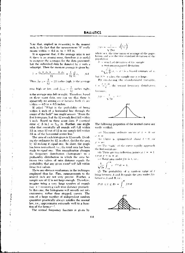
BALLi3TI __
Nate tihat, implied in irtvw-urin,., to th# nearest . , )/ •inch, is the fact that the measurement "'0" r,,alJv ,r -
means within - 0.5 in. to 4 0.5 in. 2,rc
It is apparent that, if the average miss is not wher, h1 I rii t';u ea or average oft hIe j)4i-l~a Ii )I I. ;HII 'T 1,• the t r~v ý,I .audil ard (h1-viat IIm 4 f I Iie(O, there is an aining error, therefoie it is useful iIOlI.1(Imto compute the a.'erages for the data presented. NJ St:i ,,I I liviat I;,t I (it I I ,Iit
Let the individual data be denoted by x with a itrncI-mnai-sluaiel deviatiousubscript, Then the mean or average is given by: -
+.. ! ,. - .2r: i, ;, hikased eslimal Ifu ,-t .1:2 ~12 bu"• N).1 , q %%i \hlvn the 'a:luple size it is large.
3 , ,'i1 hY nioto\ iig the standardized variahll,."rhuJt -- 5 irchl.> l iih S• lthe aN -age.il
/ . ... thec ,ol(luli. tl' uel ltic.y distrihal Ionmist high or low. :Iii) I .- h' = I Iichie, right.
is the average miss left or right. Therefoic, basedon tLse scant data, one can sav thli there i- -. ,. -/
apparently no aiming e ',)r reaosec tvth r's :u-t\,ithili -- 0.5 to + 0.5 inches. Il
If asked "'What is the. prohatbilitv of heir,.Lý•'
within qi inch of it horizontal lint- throughl the
center of the buh?" one might answer *'From thefirst histogram. 5 of the 12 rounds fired fell within!2 inch. Based on these scant data, P (verticalerror < .5 in.) = / 4n. Further, one might '[he following pioperties of the normal curve areinfer that essentially all iounds will fil within easily verified:3.5 in. since 12 out of 12 in our sample fell within3.5 in. of the horizontal center line." , M1xitum )lrli( I)'I = 4) Cir
The area of each histogram is 12 rounds. Divid- .; = ring the ordinates by 12, in effect, divides the area1),, 12 m aking it equal one. In short, tie graph a- = c,he1 akn ne Th44 al0'(> h'crer~il prlclas been normalized, i.e., the total area has been c horii. ai hmade to equal one. This normalization changes Ih1 hor' ae, twoal aXinthe frequenr'v distribution (histogramý to I hprobanilityv distribution in which the area be- 4:)r :4t " = m ').tween two values of miss distance equals the i TIual ar'a tiuilerfh') is I. i.t.probability that any given round will fall within I [ -:those t,,o values. " , "
There are obvious weaknesses in the technique ifj The probliailiry of a riadomll value of temployed thus far. First, measurements to the lyiNg ,\-viee . and 11 equals ih Itrea under ffi Inearest inch are not very precise. Further. a hI we'.I) .A 111id B. i.e.sample size of 12 is not large enough. Therefore. .8imagine firing a very large rumber of rounds I'tA < t < 8) = /(say x ) mcasurirg each miss distance preciselyIn this case, the histograms will smooth out intiicontinuous, rather than stepped, curves. Thesum of a large number of independent random
r quantities practically always satisfies the normallaw, i.e., approximates extremely well to a func-
tion of the form e-'.The normal frequency function is given by A
6-6-6
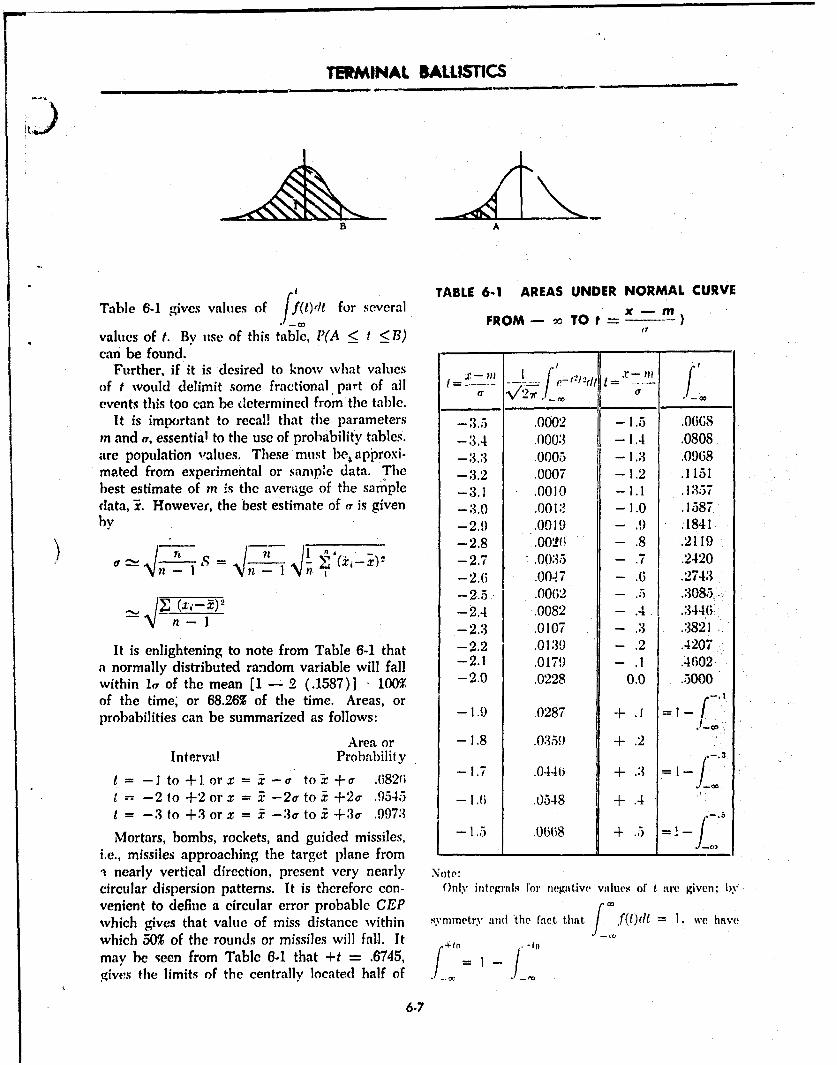
TERMINAL BALLISTICS
B A
TABLE 6-1 AREAS UNDER NORMAL CURVETable 6-1 gives values of ff(t)dt for several - M
/_ FROM-- m TO tvalues of t. By' use of this table, JYA < f < B)can be found.
Further, if it is desired to know what values X-M __ ? .
of t would delimit some fractional part of all C-r,1' t-
events this too can be determined from the table. f__ /-_. _ , . _•
It is important to recall that the parameters -3.5 .0002 -1.5 .0GSin and Y, essential to the use of probability tables. -3.4 .0003 - I1.4 .0808are population values. These must be;approxi- -3.3 .0005 -1.3 .0968ma.ted from experimental or sample data. The -3.2 .0007 -1.2 .1151best estimate of in is the average of the sample -3.1 .0010 -i.1 .1357data, 1. However, the best estimate of er is given -3.0 .00 :M -1.0 .1587by -2.9 .0019 - .9 .1841
-2.8 .001206 .8 .2119S 1 = - (-x)" -2.7 .0035 - .7 .2420
n - 2.6 .0047 - .6 .2743
-2.5 .00(62 -. 5 .3085.,, 1 -2.4 .0082 - .4 .344(6
-2.3 .0107 - .3 .3821
It is enlightening to note from Table 6-1 that -2.2 .0139 - .2 .4207
a normally distributed random variable will fall -2.1 .0179 .- .4602
within la of the mean [1 - 2 (.1587)] • 100% -2.0 .0228 0.0 .5000of the time; or 68.26% of the time. Areas, or -probabilities can be summarized as follows: -1.9 .0287 + .1 = 1 ,tI_
Area or - 1.8 .03559 + .2
Interval Probability
t -I to +1. or'x = X_--a" to3_ + a .682(6 -1.7 .0446 + .3 1 ]
t -2to +2 orx = 5ý -2atoi +2a .9545 -1.6 .0548 + .4t -3 to +3 orx = i'-3ato.±+3a .9973
Mortars, bombs, rockets, and guided missiles, .0668 + .5 = -
i.e., missiles approaching the target plane from-a nearly vertical direction, present very nearly Note:circular dispersion patterns. It is therefore con- Only integrals for negative values of t are givenl; byvenient to define a circular error probable CEP rwhich gives that value of miss distance within 4Y.vmmetry and 'the fact that/ fdt = I. whave
which 50% of the rounds or missiles will fall, It +. .
may be seen from Table 6-. that +t = .6745, f = -gives the limits of the centrally located half of / _
6-7
SALUSTlCS
A t vahies. If it is assurned there are no aiming It is sLown in more advanced texts thaterrors (I.e., n -- 0) then I CEP = 1, 1774r
(. .A knowledge of statistical analysis of errorsor (in terms of standard deviation and probable
Xbo- .67-15a, = probable error of X. erior) is helpful because the performance ofSimilarly, weapoon system components (e.g., CEP', range
Yso = .6745a, = PE, and deflection probable error, fuzing error, etc.)= •= is expressed in such' terms. Actual data for spe-
(Since, a circular dispersion pattern is hypothe- cific systems are classified and presented only insized.) classroom discussions.
6-7 PROBABILITY OF A SUCCESSFUL MISSION
The knowledge that a single round will suc- the P (kill) = P (hit) X P (proper functioningceed in its mission is influenced by a considerable of high explosive train).chain of circumstances. Consider, by way of il- The problem can be further compounded bylustration, a flat trajectory weapon with a deflec- introducing the probabilities of proper per-tion standard deviation of 1 mi, firing on a target formance of each link in tb., chain of events6 yards wide, at a range of 1000 yards. If the which precedes a kill. Inci 'd in the chainweapon is properly aimed at the center of the would be a factor for the hardness or softness oftarget, an allowable error of 3 standardI devia- the target, i.e., the probability of a definite killtions exists. This is sufficient allowance to prac- for one round. The latter involves the appro-tically insure a hit, since it has been shown thata probability of .9973 exists for limits of __ &3r. priateness of attacking the given target with theThis example has been over-simplified. In reality, given terminal ballistic effect. fence, the net.9973 is the probability of a hit on the hypothesis kill probability might take th. iorm(or condition) that the aim is correct; thus, the P(kill) = P (proper mechanical functioning)probability of a given weapon hitting a target is X P (proper crew performance).dependent on the aim. Aim is clearly a function X P (hit on the hypot hesis of proper aim)of crew training, crew eyesight, and proper func- X P (kill on the hypothesis of a hit.).tioning of the fire control equipment.
Consider the same system manned by a perfct Fortunately, most of these probabilities are, orcrew with the further condition that the projec- with sufficiently energetic training and discipline
tilte is a high explosive shell. The probability of may be made, high. The two dominant factorskilling the target is the joint probability of proper are 'obviously the size of the target and the ac-functioning of the high explosive train on the curacy of the delivery system, both expressed inhypothesis of a hit. Thus, by the Product Rule, terms of probable error or standard deviation.
6-8 DAMAGE DISTRIBUTION FOR LARGE YIELD WEAPONS
When an atomic weapon is detonated over a will vary with distance from ground zero fromgiven target it may be expected, except for un- virtually complete damage to virtually no dam-duly high bursts, that there will be a zone (ex- age. Similarly, outside of the zone of probabletending radially from ground zero) in which damage, there will be a zone of no damage. Thethere will be almost certain damage to the target. lines of demarcation betwveen these zones willIt may also be expected that, outside (if the cer- not l)e capable of precise definition. However,t,,in damage zone, there will be a zone of prob- these zones will usually exist. It is possible toable damagc in which the actual damage imposed determine thc dlistacee from ground zero at which
6-8 .....
TERMINAL BALUSTICS
"thle probadbility ol daunage i.; that desired or re- gageiment btit cilm he repaired,
qtitred. fit doing this it is ,owenient to work (c) S',ere. Permane'ntly out of aclion.
wtth that distance at which the probability of The required damage levels are moderate and
damage is about 0.5. severe.Three damage levels, light, meoderate, and The daitrige radius (R,,) is that radius (from
severe, used to describe the degree of (ldamagerO ground zero) within which as many target ele-
tactically important are defined as follows: nctets escape the specified damage as sustain it
(a) Light. Superficihl, can still pe, form outside,. R1, 1- R,,, where R.•, is the radins at
mission. which the probability is' .50 thlt a target element(b) Moderate. Out of action for present en- will sustain the specified damage.
6-9 THE DAMAGE FUNCTION
The relationslip between probability, of (ain- Z oz.ne
age and distance from ground zero as it exists o,, Zoneof Zone of no
for a given set of conditions, is known as the pdamage| dammge
damage function applicable to that set of con- i.0 - -0.9
ditions. As conditions vary, e.g., different targets, 0.8 L a
different effects, different burst conditions, it 0.7
may be expected that the curve representing the 0. -
damage function will change. These changes will 0.4 )t VAriableevidence themselves in the slope of the damage 0.3
0. 1curve and in the magnitude of R). Consequently, 0the relative size of the zones of certain dam age Distance r.m ground zero) and of probable damage change. The slope ofthe curve Ls related to a variability factor. The Fig. 6-3 Damage functions for two different setsproper variability depends upon the variation of conditions.in target response expected from the type of ef-fect being utilized, with zones of damage and radius of damage R,.
The plot in Figure 6-3 shows three curves of The least variable target, shown by a dotted line,a family of curves, eachi of which corresponds to is more discriminating, i.e., the zones of damagedifferent target responsiveness. The curve for are more sharply delimited. The most variablethe target, shown by a solid line, is annotated target has an extensive zone of probable damage.
6-10 FACTORS REGULATING OVERALL SYSTEM ERRORS
Most delivery systems are subject'to delivery lion of the actual ground zero from the planned,errors which, in some cases, are quite large. The or desired, ground zero. This is important inprobable delivery error must, therefore, be taken planning the utilization of weapons as it mayinto account in determining the probable varia- greatly affect the amount of d(mage to the target.
6-10.1 GENERAL present to the commander, recommendations on
The selection of the weapons system, a wea- weapon systems to tuse and the details of their
pon, and its delivery means, is vital to the suc- (employment.
cess of a planned atomic strike. The procedure 6-10.2 FACTORS CONSIDEREDused in selecting the weapons system is referred There are many frictors that need to be con-to as a targret analysis. The atomic weapons staff sidered in the selection of a weapons system.officer performs the target analysis in order to Generally, they can be broken down into the two
6-9
BALLISTICS
cvitegorie% of tcei~nfeatl awt! act ica! tai )r%, Un- soti It of t he s% .ti in av dli tilirtei't mt o ire iccuraitedIer any given situaition ý-vrtttn of thei fac~tors mIay dthai others. *'I'hi% factor may govern it) smiletie-ssumre greater imiportance- than others- thereby Casts wvhere troop ýafety asuranc~es cannot otlier-exerting~ a grtniter itifluc-ece oti the choice of 0 wVisv bc mtitt. Trhe aiir delivery' systomt is inher-pirticular weapons systein. entlv flexibh', yet, because of' possib*r .-nenv
(a) Mission or objective (if Hthe attack. TlhO ccunltrrueasures, weather, or navigational prob-mtost important factor in weapon selection is the lt'tns, the selectioni of such at (llivt'r% S\vStett In;V
tlbjective- of the attack. Other factors tnav have he untsouind. Add~ition~ally, the prol )letns of con--in important livar-nmt which will reqluire sonim trol and( coordination mnake it desirable that the111tlificationl ill final I \%aponls systemls selection delivery necans be tnidvr thc control of the -arm\,butt, unless the objective of the( attack is miet, the co111mmader. The( gun delivery systemn is accurateattack will viot be, successfuL. Thc results desirvO inl delivery, and net affected by weather or stib-fromn tile attack are deterittined andi vdarly stattet ject to initerception. but is liinitied in use by' itsby the commander. Mlan\- consiclera~iomis inchidl- range capabilities. Eachi sy'storn available in anying the mission, type of mnaneuiver. tari~et nature_ particular situation imist be judgeud inl thle lightanld vulnerabilitv, andI str('tvth and d isposition of, the objective of thle atornic attack.of opposingz for es, will inifluence the counmanzi- ( e) lWeapon characteristics. The( characteris-er's dc~isionl as to the ty'pe and amiount of damt- tics of the wveap~ons will also affect the final choice
agenetle aaist heentretaget r ny in some situations. For example, a certain wea-
elements thereof. 'In arriving at thle stated] ob- poll may be thle only\ onoC that hias anl uinder-jective the commander is assisted by hIds staff. g~rountd burst capability wvhereas anoth~er weapon
(b) Troop safety or other command limit.(- mayi\ be the only one capable of being pre-tions. The( second 'factor, troop safety or other )os itioned~.command limitations, also plays an important ( f) Economy. Thle third technical factor thatp art in the selection of at weapons system, Thle most be, considered is economy. The smallesttactical disposition of friendly troops andl the weapon which will achieve the desired results,protection from the effects of atomic weapons all other factors bcing equial, should lbc chosenavailable to them miust be considered in relation for reasons of oconomny. As anl example, an at-to the size o-,f the atoinic weapon and the ac- tack is being considered on troops inl forests, anticnracv of the delivery means available. Inl areas it has been determined that a casualty radius ofOCCttPiedl hv civilians. humanitarian consideration 1300 yards is needed. Atomic weapons should bemay mnake it desirable to avoid or ninfimize civil- Considered "which wvill give the required casualtyiaim casualtif s or mnalerial clanage in certain radius. All other factors becing equal the small-areas. MIinimiziing damiage to installations such est yield weapon with the required casualtyas b~ridlges, cotininiiincation centers, and other fal- radius should be selected.cilitm''s which may be of futirtor value to friendly 6-1 0.3 POINT TARGETSopc~r:ition~s. may also be specified by command A point target may be a single element. such aslim itations. Thle avoidance of Obstacles, 'ithcr at building or a bridge, or it. may be at small area
y radioactive contamination or froum rubble maLy tariget. The termn small is a relative. term. AhCe anothert litilitattionl Of thie( objective Of the(, carget is small Only iw comparison with thle radiulsathom'ic at tack. TIhe commin ider nmay well specify of d amage ( Rl, ). Thus, a very hard target (I one,MV (if the abov#' as limitations or reIsults not de- requiring high effect values) of 200 yards radiuts.%lred from~ tie atoinic attack; this, itl tim rii in ay is not a sm all target when attacked wvith a wea-rm"d ify the( finail seh.'ction of a1 wea p4itis systeml. pom; of' I1, of 400 yards. A target of Ri, -200
1 c lveapon availability ( logristics. . Weaponl yards is smiall whenci compared withi an hi, ofa.kivlabltity :mflects, tL~e finlal selection 'lot uu'1500 yards. The assumption that anti area targ-et1 r( m thme vie-wpoint, of actu alI wv Vpo li Ctli h y ca e treated as a p1oint target is lhasedl onl jimd-butt idvi I rout Ilte- vifVwjoitt (of the- r.har&i-tor'is tonvit antd the requircinetit for accuracy.
f uc i ~oF dw''o , lroltletns involving tile p~rob~abl~Iity Of (1,1nvlureI )elivrrv svstemu ;un. i-xi blitis Vou'w; de to point tunu.~ots are solved b)v nueans 4 the basicusv' '~~'.sten. m;~''ft': m Z:'tarlctcristics. point target chart, Figtire 6-4, or thec painmt tanrtrK
6-10
k4
I
TERMINAL BALLISTICS
I, IF
F- to in v Mc
qaI ! ' I
6.0
1 "'.. .. .. .... - ÷--. -
ii I- a' -t - -
* i ! - •C,o
I I"If I I i
"0IUT zJ !......Th iL -I
d ,b /Sf l OV ti "JIIVN Q "1
6-11
-1
BA0-LISTICS
PINWILITY V MAU[ TO POINT TARGETS 1114I LilXX zim CEP
(A"rap urWift)H1444+404+ H f-lifliflififffIf f7
1111ifil 1 1111
-44f+++4-j
44.1 .141 Tt44 ýiTItT4 7+4
tt tt
4'
4 t, t4 -j 4 *++-+++Fix it
44 4Tw .4. ;4.4
444
tit'I I T i I TT'
-4
4, 4-
T I
1'ý:t H, +I.... ... ....
I 1I[TTt I I ITrl
-rr42-
ELL
+T+44-- 7t
11 1111 1 lift]i I Fir I I I ffl,
t 4::+,; 1' rltl +..........
LAI I fill C,
44Vici
H ill- ... ...
20 1.9 1.5 1.7 V 1.5 1-4 13 12 1.1 1-0 3 A .7 .6 S .4 .3DISTANCI FROM 991 TO TMID CINTU/DAKUE UJM (Rd
Fia. 6-5 Extension chart, point targets.
6-12
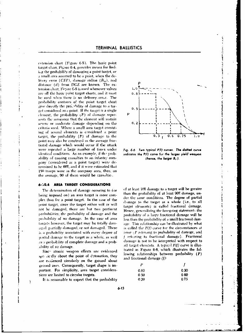
TERMINAL BALLISTICS
extension chart (PFgure 6-5). The basic pointtarget chart, Figure 6-4, provides means for find-
i.ig the probabili,iv of damaging a point target, orit small arca assumed to be a point, when the de-
livery error (CEF), damage radius (R 0 ), anddistance (d) from DGZ are known. The ex- P
tension chart, Fi -,ure 6-5 is used whenever values 1. 0 - - -
are off the basic point target charts, and it nmust 0. 8t--. .. " \I1b used when there is no (delivery.error. The ' "probability contours of the point target chart I
give directly the pro;.-tility of damage to a tar-get considered its i point. If the tai get is a single 0. 5 '
celment, the probability kP) of damage repre- Ps(ots the assurance that the element will stustainsevere or inmcerate damage depending on the 0. z * '\
criteria used. Where a small area target consist- '
ing of several elements is c-nsidcred a pointtarget, the probability (P) of damage to the 0. 3 f 0.6 0. 75 1.0point may also be construed as the average frac-
tional damage which would occur if the attackwere repeated a large number of times under Fig. 6-6 Two typical Pf) curves. The doffed curve
.identical conditions. As an example, if th. prob- indicales the P(f) curve for the larger yield weaponab)ility of causing casualties to an infantry corn- (hence, the larger R,).pany (considered as a point target) were de-termined to be 6Mg, and if it were estimated that
150 troops were in the company area, then, on
the average, 90 of them would be casualtie:.
6-'O.4 AREA TARGET CONSIDERATIONS
The determination of damage occuring to (or of at least 105/damage to a target will be greaterbeing imposed on) an area target is more corn- than the probability of at least 90K damage, un-
plex than for a point target. In the case of the der the same conditions, The degree of partiald:image to the target as a whole (i.e., to nil
point target, since the target either will or will target elements) is called fractional damage.
not he damaged, there are" hut two pertinent Hence, generalizing the foregoing statement: the
plrobabilities; thc probability of damage and the probability of at large fractional damage will be
1)probabilitv of no damage. In the case of area less than the probabi!ity of a small fractonal dam-targets however, the target may be totally dam- age. This relationship can be illustrated by what
ilutu, partially damaged, or not damaged. There is called the P(j) curve for the circumstances at
is it prohabilitv associated with every degree of issue (tP rvltr, ng to probability of damage; and
1p.krtial damage to the target as a whole, as well I reh rring to fractional damage). Fractional
,as at probability of complete damage and a prob- dlamage, is not to be interpreted with respect to
ability of no damage. all target elements. A typical P(f) curve is illus-
Sine- atomic weapon effects are evidenced trated in Figure 6-6, which illustrates the fol-
spi; ,iuAlly about the point of de°tonation, they lowing relationships between probability (P)
are evsienced circularly on the ground about
ground zero. Consequently, target shape is im- -portant. For simplicity, area target considera- 0.80 0.30tions Ire limited to circular targets. 0.50 0.60",
It i5 reasonable to expect that the probability 0.20 0.75
6.13
I ' ,-
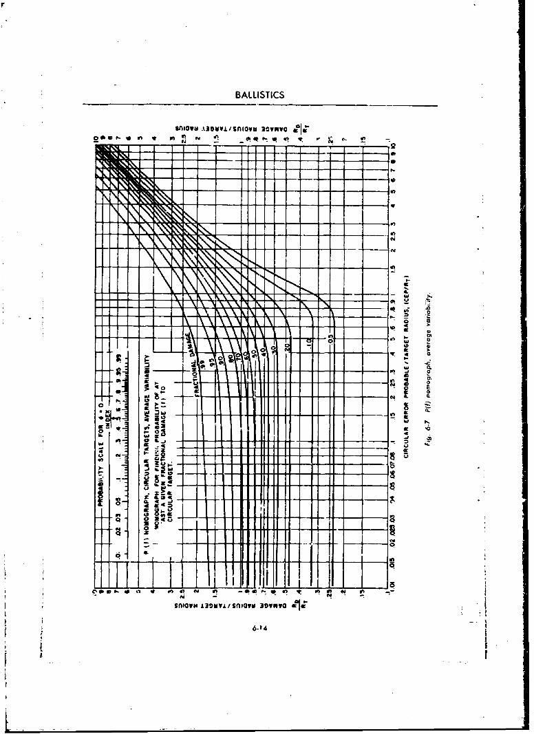
BALLISTICS
sngaWU A30VV/sniova 3ownwo
IN,
4q .4
Xg
_ 53
r N
SnaN.3M.rSlUM3vw
49 de zo
tS
TERMINAL BALLISTICS
6-11 THE PMf RELATIONSHIP FOR CIRCULAR TARGETS, NON-ZERO CEP
Figure 6-7 has been designed to enable de- it. For example: it has been decided to imposetermination of the P) relationship for circular a 40T fractional damage on a designated targettargets of radios R, when attacked with a wea- and that there be a 90% assurance (probability)pon of damage radius R,, delivered with a eir- of attaining at least that damage. This nomo-cular probable error (CEP), provided the. desired graph, together with the probability scale asso-ground ýtero (DGZ) coincided with the target ciated therewith, enables determination of thecenter. Often onec is not concerned with the en- required R,) to comply with the commander's
tire P(f) curve hut rather with a specific point on desires, provided the DGZ is the target center.
f6-12 IRREGULAR TARGETS
""a) Targets which are not generally circular (R, = )i%/ab-, where a and b are the lengths ofin shape m.-y be considered as foilows: the major and minor axes, respectively.) The
1. Rectangular targets. Targets roughly rec- area may also be found by approximation, bytangular in shape with the long side less than planimetering, or by counting grid squares.two times the short side can be reduced to an (b) Irregular targets which are not amenableequivalent circular area without serious error. to reduction to a circular target ef equivalert
In using the charts and nomograph, Rr should area must be considered as a system of points.
be equated to the radius of the circle of equiva- Targets such as marching troops or arworedlent area. If" the sides tf the rectangle are X and columns, or other very linear or irregular targets,
,can only be solved by considering a series ofpoitns within the area of concern and determin-.X.I) ing the average probability of damage. The
=0.564 VY" greater the number of points considered, time
permitting, the more accurate the determina-2. Elliptical targets. If the long axis is less tion of damage will be. The damage determined
than twice the short axis, the area may be will be- that which can be expected on the aver-equated to that of a circle with no serious error, age.
REFERENCES
1 Burr, Engineering Statistics and Quality Con- Graw-Hill Book Co., Inc., N.Y.trol,McCraw-Hill Booký Co., Inc., N.Y., 195n. 4 Scarborough and Wagner, Fundamentals of
2 Freund, Modern Elementary Statistics, Pren- Statistics, Ginn and Co., Boston.ticc-Hall, Inc., Englewood Cliffs, N.J. 5 Woodward, Probability and Information
3 Goode and Machol, System Engineering, Mc- Theory, McGraw-Hill Book Co., Inc., N.Y.
6-15
-I4

BLANK PAGE
7,-W - -
CHAPTER 7
FRAGMENTATION
ti
7-1 INTRODUCTION
* When a charge of high explosive detonates in- little value. Knowledge of the fragmentationside a closed metal container, the container is process is therefore basic to the design ofblown into fragments. These are hurled out- many types (,' missiles. Terminal ballistic
wards at high velocities and in effect become stidies attempt to determine the laws and con-projectiles %with it capacity foi inflictiný damage ditions governing the speed and distributionupon nearby objects. Capacity for dama;e de- of fragments; the sizes and shapes that result
pends uponn fragment size, belocity, and dis- iroin the bursting of different types of con-[ tributi,in. A container which erupts intu dustliko tainers, and the influence of t~he btirsting charge"
particles or int.) a few very large pieces is of fragmentation.
7-2 NATURE OF THE FRAGMENTATION PROCESS
Upon detonation of the high explosive in a enon of fragmentation as it occurs in artillerymissile, the metal case expands very rapidly shell. There are nine pictures (Figures 7-1. (a)because of the internal pressure of the expaIMiling to (i) incl,). Figure 7-1(a), the reference pie-products of the detonation. turc, shows the shell before detonation. Ex-
Flash radiographs of a tetryl loaled 20-mm posure time Is approximately one microsecondshell, detonated statically, illustrate the phenom- (1 1,000000 of a second).
7-3 BALLISTICS OF FRAGMENTS
Fragmentation is not the only result of detona- the velcity becomes equal to that of sound intion of explosive missiles, since only forty per- air.
cent omf the gas energy normally is absorbed in It is apparent that it is difficult to obtain ballis-the fragmentation process. The balance of the tic data on individual fragments; nor is it neces-available energy is consumed in ;he creation of sarv. Statistical analysis of the fragmentation ofa compressive wave in the air surrounding the the whole container provides essential practicalprojectile. The fragments resulting from detona- data. The ideal fragmentation missile is onetion of a missile arc propelled at high velocity, which would break up into uniform fragmentsand -vithin a very short distance from the center with a size and velocity fulfilling predeterminedof explosion, pass through the shock wave which tactical requirements. This ideal has not yetis retarded to a greater extent by the air. The been attained, but the size and shape of frag-velocity of the shock wave in air is dependent ments can be controlled to a limited extent.upon peak pressure in the shock wave front and The problem of determining optimum fragmentsthe piessure, temperature, and composition of the illustrates the need for fragment flight charac-undisturbed air. Its velocity is reduced accord- teristic (drag) as well as the vulnerability of theing to the square of the distances from the center prospective target in terms el fragment mas'.
of explosion until, at a considerable distance, and striking velocity.
7-1iI
,e1

BALLISTICS
Fig. 7-1(a) Shell before detonation-
Fig. 7-1(b) Shell two microseconds after initiation
of the bursting charge.
Fig- 7
-1(c) Five microseconds after initiation :how-ing the shell case in the process of swelling.
Fig. 7-1(d) Eleven microseconds after initiation4 1 .1 crocks can be seen in the sl,-l case which hasexpanded to almfst twice its original girth.
Fig. 7 -1(e) Twenty microseconds after initiationshowing continued lateral movement of the shell"case fragments. The expanding gases are escaping
through the failure crocks.
Fig. 7-1(f) Thirty-four microseconds otter initiation
showing continued growth of fragmentation per-pendicular to the longitudinal axis of the projectile.
Fig. 7 -I(g) Thirty-nine microseconds after initiction.
Fig. 7-I Detonation of a 20-mm shell. (Sheet I of 2) " 1j 7-2
i1
]
FRAGMENTATION !4
Fig. 7.1(h) Fifty.fcur microseconds after initiation
showing the extent to which the frgragments fly off in
the direction perpendicular to the surf ac* of thecasing. The disc shaped side spray which exceedsthe noso ond fall spray in intensity of fragmentationis the main instrument of damage in most missiles.
F "
Fig. 7-1(i) Ninety-two microseconds after initiation
showing the wide ,arionce in size and shape of frog-ments. All the fragments chave by now received their
initial velocities.
Fig. 7-1 Detonation of a 20-mm shell. (Sheet 2 of 2)
- 7-3
I
. . . .. .
BALLISTICS
7-4 INITIAL VELOCITIES OF FRAGMENTS
*The initial velocit-y% of a fragment depends to dto %vork over an area, a property m~ore die-mainlv ont: peodent on oxygecn balance and after-burning
(a 'IThe C 3if ratio where (: is the mass of tIhali onf rate of' detoniationl. On the other hiand,vxplulsiv( iwr unit length of projectile and '11 is brisance has beun defined its the ability to creaitethe inass (if metal per untit length of projectile. destruictionin t the iflmmediate NicinitN tit the ex-
(h) Thev characteristics of the explosive filler p)losion,. which quiality appears to be (leteiflint'l(brisatice. h.%e -b the speed of cstahblishnioeit and thc iu1:1iiitode
Table 7-1 illustrates the relationship between of pressure intit t' detonation wax c.
CMI ratio and initial velocitic, W1,j dleterminied TABLE 7-2 COMPARISON OF FRAGMEN.from a series of tests using "-lind~en, of anin lter- TATION OF 90-MM M71 SHELL USINGnit] diamineter of 2 inchtes -ind uniform wall thiick,- TNT AND COMPOSITION Bnexses as indicated. li''I, explosive filler used was _______________________________
TTNT.*TABLE 7-1 FRAGMENT VELOCITIES FROM Imdn 1 sI~t loIn* I ~~~VARYING CONTAINER WALL THICKNESSES g~ oii
* alInches IlragmnteiitThianel W g it I'ragnieritat iona
_________Ia/8_K__IV Tests 1 700 I 9CM ~ _6 .t3I21 286 I5Q -
I*. (ft ,ev) 2A7,0 3-240 :1S800 5100 i C.100aget e~etPj I anel Peoet rat ion I
Initial fragment velocities can be estimated cx- Te: f .32 ft*pt-rimentally by measu ring fragment peneiltrationf P'erforation in Sivetinto at muaterialI su ch as soft pine or celotex, an flll litit e tl(I al rmo ii) I 16,4adjusting estimated velocity in terms of fragmentMass. shiape and di ag cozffcie-nt. Semni-empiri- The best %%ay theai to at-louvc high init ial \v-cally, the approximate initial velocities are, ,'iiso rgnns stnv itiC i
ratio. usitall' obt ained in A pract cc b\ thl us o
=K M4 =K '*±~ a thin -walled containcr. Thij. is not .ilwavs pos-.1+C2 1+12 C' 31 sible how'-ver, smin:c in ni.III tascs piolit-c
where most he d -signed with thick Nvalls to withstandsetback forces or the% ma% he piirposclv designed
* V = inhitital fragmen t Veloitiiy. ft 've t:j give lakrger fragownet s. Iit Iilki-se cases a moire* K constant assoite with the in(] powerful exp~lo sive is needed having at higher
* brsamce o th exlosie msedbrisancc thani that osed in a thinner wvalled cvlin-*C aiid If. as defined aboive (ter. Explosives containin!e TI)X, for exam'ple.
The primary reason for the rclat;ely lo", .e- have both high brisance and goodl jiower. Theylocities of fragments from the container with the are ideal then for producing bight velocitv frag-greatest wall thickness, is that a large part of inents. although for certain applications thce' are-the energy, ieleased by explosio.- is absorbed in too sensitive.rupturing the cylinder. 1IoxiL,%cer. the table could Velocities (if fragments from an air burst havebe changed consider-ably either by the use of higher values than those obtained fromt detona-different explosives, particularly those whose lion upon impact dule to the velocity of tite mis-Power andI 'orisance differ, Or byv different wvall site at the time of detonation. Thi's fact is onematerial such as east iron versus forged steel. of the reasons why \VT or timfl! fuzing providesExplosive power is usually considered as ablt more effective fragmentation effects.
/ abilit
FRAGMENTATION
Fig. 7-2 Static nose-down detonotion of o bomb.
7-5 DIRECTION OF FRAGMENT FLIGHT
The fragments from a missile usually fly in a The fragments ahrlmt parallel to the grounddirection perpendicular to the surface of the constitute the main side 5pray and originate fromcasing. For an artillery projectile, this can be the cylindrical side walls of the bomb. The pic-readily seen hv referring again to Figure 7-1 (i). ture does not do full iu-tice to the great densityFigure 7-2 shows the static detonation of a large of fragments in the side spray. The slight up-bomb suspended nose down with nose about ward deflection of the entire side spray is due
* seven feet from the ground. The tracks of the to the fact that the borr' was detonated stati-fragments are made luminous by their heat. callv nose down, and the detonation started
Note the black smoke, which represents the tin- from the bonmb nose.oxidized ;olid prodmcts of the explosion, an in- If either the bomb or shell had been detonateddication of the incomplete oxidation of the while in flight bN VT fuze action, the side sprayexplosive charge. The cone of tracks, opening would have had a slight forvard thrust; the
* upward in Figure 7-2. is called the 45' spray re,ultant of the radial initia! velocity of the frag-i and orivinate-s from that section of the casing ments and the forward velocity of the bomb or
* that connects the cyvlidrical part with the tail. shell.
7-6 NUMBER, TYPE, AND SIZE OF FRAGMENTS
The damage that will be produced by a frag- fragments is det-rmined experimentally by meansment with a given veiocity depends on the mass of static detonations in which the fragments, orof the fragment. It is therefore necessar' to know a portion of them, are caught in sand pits. Usu-approximately for each missile the distril.ution ally, the side spray contains the most important
of mass among all the fragments large enough part of the fragmentation. Such a spray will, into cause damage. Mass distribution of missile general, have a different mass distribution from
7-5
L 4l
BALLISTICS
algae Is do Isd IIon*
*.* G : r 46090,04
5 eagetcii 6# 3 lo it G Dbb@ 1114
-'I.'of 19
9G:116 VII
W, Hs ~
Fig- 7-3 Frogmen's from bomb, fragmentation, 220-lb, AN-MK.
that of fragimiots from the x%!iole missile. In the the fragments of at gviwial-purpose boimb. Frag-static detoniation~ of b oins, portions of the side ments wvill vars from oihist-like particles to rela-spray. nose sprai%, fir tail Fpray art- collected in at tvylarge piecvs ill (;I, 4ombs. wheret fthe size,andi pit The fragments art, separated from the of fraiments is not controlledI.sand bV siftiag thr 'ugh metval screens of four While adjustment of thec C Ml rati Iin shvillsmesh too the inch. The fragments thus obtained, can be used tu change the deg.ree of fragmcntat-few (if which havte masses less than one griam. tion of the shell m all. the size anti Iinumber ofare- then weighe-d and classified according to their fragments reStdtiiig from the( shattered %%all canmasses into no more than six laswes. Suich sort- also be adjusted E% altering the material useding is shown in Figure 7-3~ which represents in the wall. Fo)r example grey cast iron, ani in-recovery of fragments oif an \t88 220-lb frag- herently brittle material, shatters into very smalltoentation bowl, loaded with Composition B. sand-sized pieces which have tow% killing power.
in general, the shape of the fraements vanec Also thev have little rromentum and thvs shortt'xceedinglsi. Nan% of themn appear flat, their rne.Tiisisftuteinhe(itn i
sinaiest (hlflefl5~ii. co rri-spiijiiling to tlke thickness shnell bTdis is defirtuable fromt a!htbIlizatingO
of the swollen case, stretched hv the expan. shell bofie iew. iabefo i oilzto
sion that follows (detonation. Present fragmen- pitovew
tation bombs have a light :asing wrapped with A vital factor in the design of anv ammunition
it metall helix of square cross section in order to ie sisaiiyt eraiyaatbetcorntroll to somne extent the size-, aind therefore the quanitity manufacture during mobilization or
distribution of mass among the fravgments. When Nvar. This country has a broad base- of industrythe bomb bursts, the helix is broken into pieces which L,Altl cast shell bodies. On the other hand,of oomparatiselv unihifr A ; compared to because forging is at widely used commercial
7-6
FRAGMENTATION
iinettjn if I iftabrit at Nolt t Iit i t.It lIi~ r% ttl thtis lit rt'dlicdl it 4 tist iron wetre axviilalil 'vhielctliiitrv cain so lpp rt Vc~LUii ial vc l'ii.tiiifac - tcliti li bcmae o hitl v t lalt into, fragoirnts LIf opI-
or. (of lrtlshill loic-it, lit liko iil.Iiui-r ini I iinnm sue~ Spliutroiiduize cast ironi in xhichi tileV(t L 11 t t.,i r-.. (t ),I , % s attI, ottiý, i tI co~ld v triisitit .11 )1 11,, ilsr iliut i i oi ( ei nodutlalr diistrib~uution asjtI t(s.\it s kt '. INit It)( t.1` 1il) )ttp %%u sitli fio, m .1, stel vin Fu l ) can hie colntrotlledl by heat treat-st iit alt - tnit -t i . (ki i' f s 5a 11 11 iuinmitif.,( INi rm. 1lillit , SiIN, vs Some1 ~itq0111i.S illI i I ifi IIitig thI is re'-
Metal whichi defoirums withouit splittiiii. iii thest- qiiirvuitnct. W~ithu rigid rnetalitrP- oru itroljIresSIIr.- fomirnig, prot -e.scms is, on the whlt-lu ;act imrc% at tile iii(ttldjiS which act as Stresstugh ard Ilaitd to %I attcr. I h-imc. \oiw o advaim rvivo-' rs 'Mcl cast irn Ln an bv imide ito givse frag-
tage iii bohIt proi .iu -ttIl and fragM i-nt at 0 ao l Ingt invit s of de-s 'rdlc Size.
7-7 FRAGMENT DAMAGE
In vaI tiat ii g thI e effect i ve-nss tof fragincl(nt a- d it itgV p~atter us o f t vpc il mindvidutalI cases, asItillii ofR' speific %eapons (Ivinmuius are mistit as anm iitms ni in Ftinures 7- 11 an'i 7-5, illustrate how thee'xample , ) , 1iw to-Ipes (it daw ige ctinsidere'd are terminal oetIiyf the hoinmih, the angle of fall,tas!ialtics. tuidt normtual ps-rforati in of mild steel And the height oif hurst influence fragment dis-of !-inch. '4'-in':h. and !2-inchi tuict -nvss. .-X asumalts tribomtion. Boithl fragmentt damnage tables andmay K- defitued as it liti hv a fragmnent wvithi at 'lamiut pattum lprestimppots a graze (Jr air bursth ast 58 fit t -notnomds o f 'ncrgv. ( This ride (if with ri ntxl hiv dug i f tlt tearget. Coinsequm ently,t'iuumh has been sitjersecli.-(i by woidiniillg, en- in uising, Such data allowance rin'mst hi' made forteria of nituuci greater refinemenet fon use by target shielding and] tile penetratinfl of the bombNvi-api ns designers and~ fragnwentatiltn iffi ctis'e- iatti the groilulid before burst. The amount (if 'hisness stutties. ) Normal perfotratio n olf mild ste-el penetration will depend uponii the remaining ye-occurs w.hen ia fragment, traveling perpendicular iticity, the angle mof fall of the bomb, the naturetoi the face ilf thle 1)ii tc passes comtnplet ely of thle Stiil, a111d tit- type of hiomb And fuze.thiroughi tthe piate of the indic-ated thickness. The tlptimin~m height uof buirst whierK will giveD~amage in which t here is perforatio n oIf !;-inchu thc inasimmini numhct oif personnel casualtiesmild steel is effe-tivc- against airplane-s Ill the may be read frottn Figure 71-6. 'When a fuze forgroumndl. Damage in wbich there is perforation regulating the height of burst is available andof "_in(LIJ mildI Steel is efiCt ive againSt trucks, eam'ses a known dispersion in the heiight of burnt,Daimage in whtIii~ there is perforation iof t4-incli it is p,'ssihlv to its.' Figuire 7-6 to dletermine themild st -cl is effective against light armilreu hmean height to whic-h the burst should he ad-vehicles, railway rolling stock, ;andl targets of jumsted.similar resistant nature. Air btir ts are recolmmendedl against men in
The fragment damage shown in Table 7-3 ohitsoopnrnceadagntpronlgives the mnuiber, B. of effective fragmeints per shielded bv rougih terrain. The type o.f shieldingsqutare foo~t of target area at a given distance r laheled "1~foxholes" is believedi to lis that motfrom the burst oif a 220-lb. bomb, based (in an commonly encoumntered and corresponds to theinitial fragment velocitty of 4420 feet pe- second. shielding'afforded men in foxholes when the menThe nuimberE, B, are averages for different direC.- arc somewhat below the level of the ground, ortitins from the burst, and are side wall directions. tIa the shielding afforded prone men by roughThey apply only to a considerable number of t,'rrain. A "10' foxhole" is defined ais a foxholebursts with random orientation of the bomb axis in which an occupant would be unharmed byrelative to the target. The actual density of frasgments with an angle of fall less than 10 de-fragments in the most dangeroius dieetion from grees. Hastily dug-in positions on level ground
' the bomb is about six timnes the average den- would cor.-espond to "0- foxholes," as wouldsities, H, given in the table, trenches in which the h.'ads of men are even
As distinguished from fragment dlamage tables, with the ground.
7-7
4
BALLISTICS
TABLE 7-3 FRAGMENT DAMAGE: CASUALTY AND PERFORATIONEFFECTIVENESS OF BOMB, FRAGMENTATION, 220-1b, AN-MSa; CO,.POSITION B LOADING; INITIAL FRAGMENT VELOCITY 4420 FT/SEC
Disapce Total Average For the LightestrmNumber of Effective lFragmentFromf Number of E ffect ive
Burst Effective raents WihVlitill Feet 1FragmenIs F'ragmenits Weight, Velocity,inFet rameqsper sq ft oz ft see
r I B in
Casualt ies
40 8650 .705 .0073 285050 8000 .418 .0101 242060 7400 .268 .0134 210080 6.10M0 12'3 .0217 16,50t
1100 5800 .0757 .0322 13601504 4500 .026 1 .0609 968200 3700 .0121 .0857 832300 w 2800 .00406 .137 61h85Q1) 1920 .00100 .26•8 471700 1500 .00040 .443 :i(i5
1000 850 .00011 .808 271P e r fo ra tio n o f n - in c h M ild S te e l .0 0_8_ 4 4 2
:120 82700 1.0I6 I .0108 4472020 8200 2.16.084030o 7300 1.06 .0140 -3720--
40 6600 .538 .0205 326060 5600 .203 .0364 2(40
100 3750 .0489 .0845 1970
150 23;00 .0133 .188 1550200 1750 .00571 j :1.5 I",0o300 990 .00144 .72)0 -O0400 420 .00034 1.14 913600 28 .f0}KA1 2.13 770
P'erf,,ration o. 1/-inch Mild Stee!
20 4100 1,34 .0718 442030 3600 .522 .0917 104040 3180 259 .112 375060 2520 .0914 .162 327080 2100 .0428 .220 2910
100 1860 S0243 .289 2640150 1350 K00783 .517 2180200 820 .00266 .822 1870250 336 • .00069 1.22 1640
.300 67 .00010 1.72 1-490__Perforation of-i b Mild Steel
20 1220 .398 .580 442030 1090 .158 .660 422040 920 .0750 .750 402060 650 02:36 .925 371089 420 .00857 1.11 3480
100 250 .00326 1.33 3260120 1'0 .0)1109 1.55 30S0140 60 .00040 1.79 2920170 26 .00012 2.20 2710200 13 .00004 2.65 2530
7-8
FRAGMENTATION
rAct,"" ow no
AT LOPhIMR .r'.
4NWAC OIA- 't S/
Fig. 7-4 Damage pottern: bomib, GP. T
Mmml ~ P~ I ftu o . FT .*
sla IwM " 90430
AT ".* W! IS Wf PV 1AP W
Fig. 7-5 Damage poflern: bomb, GP.6
7-9
BALLISTICS
n~. - . t.k
=- q Y i o
VU.
30
/-,/30 .40 V-Mv.
10 20 3o a W 40 • 0 s 90 tooHCDG! OF MWU Ph m*A POog*,
Fig. 7-6 Casualties versus height of burst-bomb, fragmentation.
The optimum heights of burst for various types desired. In this table the grou;ps of bombs corn-of bombs run approximately as foliows: pared are those nermally carried in the same
station of the bomb bay. The figures given areOpt imiur H-eight ofBomblieB rst N erion ratios of effective hits of the type indicated for
Bomb 2iller rst, N( 2 ipersi the bombs compared. The type of explosive20-lb F'rag (TNT) 20-;0 ft chaige used in each bomb was giv2n in the pre-J90-lb Frag (Comp 13) 3f 50 ft ceding paragraph.
100-1b OP (Amatol) :10-50 ft An examination of the data gven indicates2100-lb Frag (Comp B) 35-70 ft that at low or medium altitudes a 20-pourd500-lb GP (Amratol) 30-(i0 ft fragmentation bomb is preferred against person-
Table 7-4 will be useful in making a choice of nel or lightly protected targets. For low altitudebomb for ground burst against unshielded tar- bombing, the parachute on a 23-pound fragmen-gets according to the type of fragment damage tation bomb greatly improves its effect over the
7-10
V
FRAGMENTATIONVI
TABLE 7-4 FRAGMENTATION COMPARISON: RATIOS OF EFFECTIVE HITSOBTAINED FROM VARIOUS BOMB COMBINATIONS AT VARIOUS ALTITUDES
OF RELEASE
1: lIatio of Fragments Irom Bombs Compnred ý,uusin6No. and Type c" Altitude
Bombs ('onipared of Attack ('asualties I •" perf. Y' - perf'. W" perf.
Six 20-lb frag I ow' 1.83 2.38 I 094 ....O)n<, IO0-11) ('.P 109O(00 ft, 3.00 1 2.48....
120.000 ft 1.67 1.19I 30.000 ft 1.05 0.79 .
Si\ 20-1h frag Lo .- 0-605(bi1 260-Ih frag I0,000 ft 1.41 0.88
20,000 ft 0.68 0.40 .30,000 ft 0.51 1 0.35 I.......
One 1l0-1b Gi' ILow 0.56 0.40 0.55 1
(hie 26;0-1h fag 10.000 it 0.47 0.35 0.4920,000 ft 0.41 0.33 0.47'30,000 ft 0.48 0.44 0.61 ....
Twenty 20-1b frag Low* 1.0.5 1.07 1 0.69Six '90-9h frag 10,000 ft I.(55 0.81 ..
20.000 ft 0.7t 0,66:30,000 ft 1.08 0.65
'wenly 20-11) frig ILow* 1.91 2.05 1.12
h)e 500-1) G-P 10,000 ft 2.88 2.1320,000 fh 1.86 1.38
.30,000 ft 1.46 0.99""-.------,---.----- -- I- ____
ix 91lw 1.81 I 1.92 1.45 028
O- .-)e0-1b GP 10,000 f ?, .7i 2.64 1.80 ...20,000 fl : 234 2.09 1.32 ..30.000 ft ' 1.31 1.51 0.98 ........ -. -. -... ... .. .....-.....-.-i ... . . . . I .- .. __ _ -__ _
Two 100-l, G P . Low 0.79 Oti0+6 0-67
()Ile 500-1b GP 10.000 ft 0.78 0.6( 0.6820.000 ft 0.815 0.7; 0.7430,000 ft , 0.93 1 0.75 0.78
"I wo 260-1b Crag 1.,o% 1.42 1 .61 1.21 0.85
J•)rw 50(-lb (;P 10,000 ft i.65 I 87 1.39 0.9820,000 ft 2.09 2.14 1 58 1.13
30.000 f; 1.91 1.70 . 1.27 0.91"*j,, i , w nititudle Imoml wi the ,.ff .iv, ,..,, of fragmentatimi homt p itt Iu 0: r.at ly in erea sed if the parafrng
SII, N1 It or 120-11t N1.16) is u',stituted ior hli ,.orresplndiu g fin-.tabilized-fraK
7.11
.. . . . . . .- ..-..
BALLISTICS
nonparachute bomb which, except for having clusters of six, and when so used will he particu-fins instead of a parachute, is identic;,I. When larlv effective if the required damage is, at most,released from high altitudes, a fragmentation equivaient to perforation of 39-inch mild steel.bomb is reduced in effectiveness. The bombs are When this bomb is used in individual suspension,used in accordance with the type of damage substitution of the 120-pound parafrag may giverequired, consulting specific fragment damage increased effect from low altitudes. For heaviertables and damage patterns discussed previously. dimage the large fragmentation bombs or theA 90-lb fragmentation bomb may be used in 500-pound GP bomb may be used.
7-8 SWELL FRAGMENT DAMAGE
The analysis of fragment damage from artillery range, and that the effective damage ot the targetshells is very similar in priniple to the preceding requires fragments which will perforate h-inchanalysis involving bomb fragment damage. As in mild steel, it can be determined from Figure 7-7the case of bombs, tables of fragment damage that the minimum number of shell for this rangeand damage pattenis. both of which give data on would be required if charge 5 and high anglefragmentation effect, have been prepared for all fire are used.standard high explosive artillery shells.
In addition, tables of shell density in area fire In general it may be stated that ground burstsare available which give the number of shells are recommended in most cases where the tar-required per unit area to accomplish specified gets are relatively unshielded. Air bursts are
effects under various conditions for both air and recommended against men in foxholes or openground bursts. Such a table for the 155-mm trenches and against personnel shielded by roughHowitzer firing HE shell M107 (ground burst) terrain. For the 155-mm shell, the optimumis shown in Figure 7-7. Assuming that an area height of burst against shielded personnel istarget (100 ft X 100 ft) is assigned at 10,000 yd: between 25 and 50 feet.
7-9 CONTROLLED FRAGMENTATION
From the discussion thus far, the important (b) The velocity of fragments.characterist.',.s of missiles designed for fragmen- (c) The direction of flight of fragments.tation are: It can thus be stated that a controlled fragmen-
tation missile will be one in which the configura-(a) The mass distribution (number, size, and tion, direction of flight, and velocity of each
shape) of fragments. fragment can be predicted.
7-9.1 DIRECTION OF FLIGHT 7-9.2 VELOCITY
The direction of flight of fragments will de- The velocity of fragments is the next point topend on the shape of the missile. The best shape be considered. From the discussion in Par. 7-4,is one that directs the flight of fragments so as above, it was explained that thc initial velocityto give the maximum effective area of fragment of the fragments depends on the charge-massspray Unfortunately, the shape of the missile ratio of the missile as well as on the type of ex-is not governed by the terminal ballistic consid- plosive used. The charge-mass ratio of a missileeration alone, and therefore some compromise is inherently govrrned to some extent by designin the ideal shape oi missiles is necessary to meet considerations other than purely terminal bal-interior and exterior ballistic requirements. listic requirements, as is the type of explosive I "
7-12
T
FRAGMENTATION
,- 'SO DAAGE MASTS
5 20 EL1M0 SHIELD"T
I VUUERAUI *r GE
I CCIb1 Of PUUh S I
,;t.1s~*- DAMAGE TYPE
a 0 SO By NUpMBE OFEUNEMYSL PESON
20WIDTH OF FNIKG-37 P1
'2O DN"TP
:7;~PE I/* 7I13 STEEju11 L~2Z
BALLISTiCS
Fig. 7-8 Experimental grooved ring shell body.
I
II
.~iIFig. 7-9 Uniform fragments obtained from grooved ring shefl body.
7-14
FRAGMENTATION
used. For instance, sensitivity of the container ,and of tie explosive to set back, among otherconsiderations. presents a limitation of the typeof explosive used and on the charge-mass ratio.
A direct mechanical control of the number,size, and shate of fragmný'nts offers the best op.
portunity for controlling the fragmentation effec-tiveness of missiles. As mentioned in Par. 7-6,
above, such control has been achieved, to a de-
gree. in standard fragmentation bombs by wrap-
ping a metal helix of square cross section aroundthe charge More recent methods of goveming
the mass distribution of fragments, although still
ii the experimental stage, offer consid rablechance for improved control. They are;
(a) Use of notched wire of square crosssection.
(b) Use of grooved rings of square cross sec-
*• tion.: The first control method listed above is similar
in principle to our standard fragmentation bomb* case design. Figure 7-8 is an illustration of the Fig. 7-10 Uniform spacing of perforations
body of an experimental grooved ring shell. The in 8,-inch steel plate obtained by groovedgrooves are equally spaced around each ring, ring shell.
being relatively shallow in depth and triangularin cross section. The rings are assembled or. theliner and pressed together as tightly as possible. shell in Figure 7-8. when it was placed eight feet
Retainers are fitted suffiliently tight on the liner above a mild steel plate (6 ft X 8 ft X 5,16 in.)
to hold the rings in place. and detonated statically. Large holes indicateFigure 7-9 illustrates the relatike uniformity of perforations.
the controlled size of fragments achieved by the Figure 7-11, showing nine spark radiographsgrooved ring method. It should be noted that the of the detonation of the grooved ring shell illus-close uniformity i size and shape of fragments trated in Figure 7-8, depicts the progress of con-will result in greater uniformity of striking ve- trolled fragmentation. Pictures (g) and (i) oflocities. This. to repeat, is a direct result of the Figure 7-11 are side views, while the other pie-more nearly uniform initial velocities and uni- tures are top views. As a matter of interest it isform presentation areas offered by the fragments well to compare these pictures with the sparkas they fly through the air, which results in more radiographs of uncontrolled fragmentation inuniform retardation during flight Figure 7-1. The comparison suggests that one
Size, and therefore mass control, of fragments accomplishment of controlled fragmentation, athas been achieved in both notched wire and least for the grooved ring type, is a higher degreegrooved ring shell by accurate spacing of the of uniformity in size, shape, and intensity ofnotches or grooves. This spacing is based on the fragmentation. If the grooved ring missile wereassumption, thus (a' borne out in test firings. detonated in a position such that the target was
that there is an optimum width of fragment for in the side spray region, probability of targeteach size and type of shell, damage would be higher.
Figure 7-10 illustrates the uniform spacing of A current item of materiel employing the con-
perforations, achieved with the experimental trolled fragmentation device of the rectangular
[ -
BALLISTICS
Ftg. 7-11 (a) Fig. 7.11 (b) Fig. 7-11 (c)
Fig. 7.1 (d) Fig. 7-11 (e)
Fig. 7-11 (f) Fig. 7-11 (g)
F g. 7Fg. 7-11 W
Tg. 7-11 Velinofon of grooved ring 5hel1
7-16
FRAGMENTATION
AJ
Fig. 7.12 Hond grenade.
grooved wire. easily fabricated, and highlv effec- ing optimum-sized fragments, sub-projectiles, ortive when matched to the weight and brisance of aerodvnarnic bodies into the target. The studentthe explosive, is illustrated in Figure 7-12. is alerted to be aware of the need for possible
Security classification precludes illustration of solutions to the problem of fra)4mentation in hismany additional and practical sch,-mes for pro- appraisal of conventional and wevhlopmefntal amn-
vicling controlled fragmentation and. or deliver- monition.
REFERENCES
No genetal, unclassified references are available.
7
7-17a

I'I
"BLANK PAGE
i7
'I_ _ _ _ _ _ _ _ _ _ _ _ _
-~ - - ~ .
1•L_
CHAPTER 8
BLAST EFFECTS BY CHEMICALAND ATOMIC EXPLOSIONS
-F
8-1 MECHANICS OF BLAST
When a conventional explosive charge or nu- passes. l1cre the pressure rises abruptly from at-* clear detonation occurs in air, expanding gases. mospheric to a peak- pressure, then declines to* often referred to as a flame front, burst foi th and atmospheric pressure. This phase is known as
compress tile surroundi-ig air, thus initiating a the positive or pressure phase of the shock wave.shock wave. The gases themselves have hittle The pressure continues to decline to subatmos-inertia, cool &apidly, and will have lost most of pheric pressure and then returns to n,0rmal. Thetheir velocity at a distance of 40 to 50 times the second phase is ciIl. Fthe negative or suctiondiameter of the charge. The h.lt of compressed phase. Figure 8.1 shows a t'pi,:al pressure-timeair on the shock wave has initially a high outward record of a blast wave at a particular distance
Svelocity which it loses rapidly at first. The shock from point of detonation. The negative phase ofwave, except for its.intensity, has all the charac- a shock wave is caused by the air and gases ofteristics of a sound wave, and travels through the detonation mouing outward as a strong windsurrounding air in the same m-anner: that is. behind the shock front. They are prevented b%without the transmitting medium moving along their own inertia froin slowing down quicklywith it. enough, ais the pressur.- of the core of the gases
The shock wave is boundt-d b1 an (5xtreoelv subsidc. The rarefication thus tormed propa-sharp front called thek sl,(ck frawn which repre- tgatcs outward, trailing the positive phase. Aftersents a discontinuitv in densityv, pr'ssure, and the positise phase passes, the wind rcve-ses intemperature of the nediurn through which it dircetioin and blows toward the ponit of dIeiona-
I ,,uu . OR POSITIV IPuts5,
ofE usOE TRUE tits P1211141I F94 OUBATIOS Of ?O$05 T ?IIi S*1
at AVERAGE POSITIVE P Iyt U REP ICAIR OISTURVAN R S, I A-- OCtES -O -tog *IATI1 PST
D DUE TO FRAG JCNrs I "PASSING TWE GAGE ('J 5-AT SUPERSONICVELOC T Y IM(, TMO$SAIIm OF A $(COIII.
0 S I0s' 20 2S
TYPICIL P0t1S41I-TIP( RECORD FOR TlN @I AST ION A IA 6
Fig. 8-1 Profile of a blast waow at a parlicular distance from point of detonation.
8-1
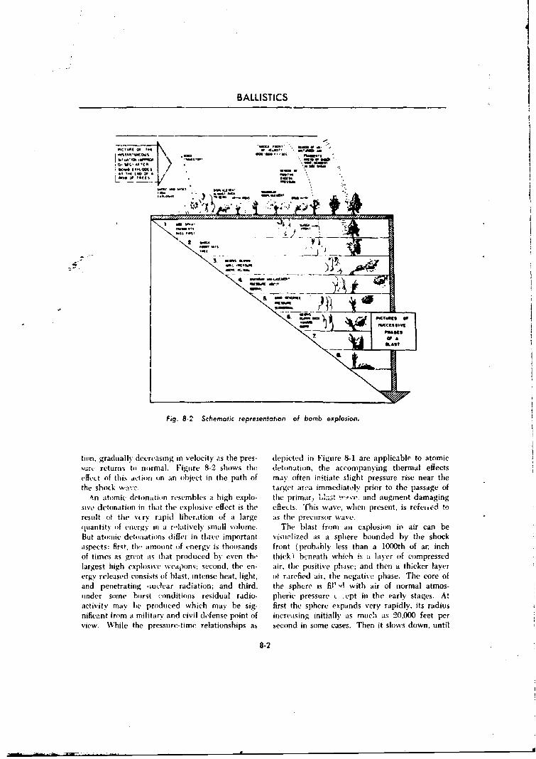
BALLISTICS
ect VTW /-
at~~~~ Al ~ n
IIFig. 8-2 Schematic representation of bomb explosion.
tion. gradually decreasing in velocity as the pres- depicted in Figure 8-1 are applicable to atomicsurv returns toi normal. Figure 8 2 shows the detonation, the accompanying thermal effectsWefet of this action on an object in the path of max' often initiate slight pressure rise near thethe shock wavc. targot area immediatoly prior to the passage of
An atomic detonation resembles at high explo- thie prirnar. iA.-t w~.and augment damagingsiv1' detonation in that the explosive effect is the effects. This was-e, when present, is reficicd toresult of the %s rs rApid liberation of a large asthe precuirsor wave.quantity of energy in a r'{tatively small volume. The b)last from an explosion in air can beBut ato.nije detonations differ in three important visualized ias at sphere bounded by the shockaspects: first, the amount oif energy is thousands front (probably less than a 10O0th of ar. inchof times as g1reat ats that produced by even the thickl beneath which is a layer of compressedlargest high explosive weapons; second, the en. air, the positive phase; and then a thicker laverergy releasedl consists of blast, intense heat, light, oif rarefied ais, the negative phase. The core ofand penetrating ouclear radiation; and third, the sphere is filut , with air of normal atmos-under some hursit :-onditions residual radio- pherne pressure ( -ept in the early stages. A'activity may 1w produced which may be sig- first the sphere expands vecry rapidly, its radiusnificant from a militars' and civil defense point of increasing initially as much as 20,000 feet perview While the pressu~re-time relationships as second in some cases. Then it slows down, until
8-2
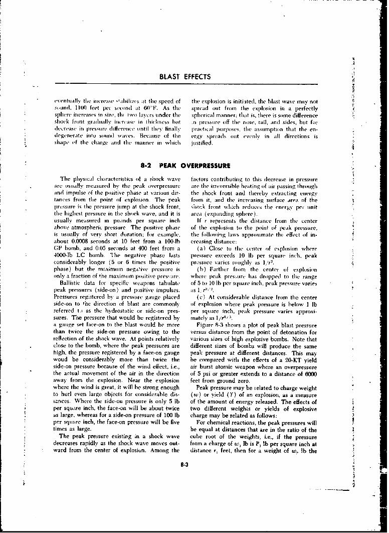
BLAST EFFECTS
eventually the increase Oahilizs at the speed of the explosion is initiited, the blast wave may nots,,ond. 1100 feet per second at 60-F. As the spread out from the explosion in a perfectlysphere increases in size, tlw IWO layVrs under the spherical manner: that is, there is some differenceshock front gradually incrcase in thickness hut in pressure off the nose, tail, and sides, but fordecrease in pressure dillerence until they finally" practical purposes, the assumption that the en-degenerate into sound waves. Because of the ergy spreads out evenly in all directions isshape of the charge and the manner in which justified.
r 8-2 PEAK OVERPRESSURE
The physical characteristics of a shock wave factors contrihuting to this decrease in pressureare usually measured by the peak overpressurc are the irreversible heatting of air passing throughand impulse of the positive phase at various dir- the shock front and thereby extracting energytances from the point oif explosion. The peak from it; and the increasing surface area of thepressure is the pressure jump at the shock front, shoc-k front which reduces the energy pet unitthe highest pressure in the shock wave, and it is area (expanding sphere).usually measured in poonds per square inch If r represents the distance from the centerabove atmospheric pressure. The positive phase of the explosion to the point of peak pressure,is usually of very short duration; for example, the following laws approximate the effect of in-about 0.0008 seconds at 10 feet from a 100-lb creasing distance:GP bomb, and 0.05 seconds at 400 feet from a (a) Close to the center of explosion where4000-lb LC bomb. The negative phase lasts i)ressure exceeds 10 Ih per square inch, peakconsiderably longer (5 or 6 times the positive pressure varies roughly as lr.phase) but the maximum nega.ive pressure is (b) Farther from the center of explosiononly a fraction of the maximum positive pres,:ire. where peak pres:.ure has dropped to the range
Ballistic data for specific weapons tabulate of 5 to 10 lb per square inch, peak pressure variespeak pressures (side-on) and positive impulses. as I; ,Pressures registered by a pressure gauge placed (c) At considerable distance from the centerside-on to Phe direction of blast are commonly of explosion where peak pressure is below 1 lbreferred t. as the hydrostatic or side-on pres- per square inch, peak pressure varies approxi-sures. The pressure that would be registered by mately as 11r4-.a gaure set face-on to the blast would be more Figure 8-3 shows a plot of peak blast pressurethan twice the side-on pressure owing to the versus distance from the point of detonation forreflection of the shock wave. At points relatively various sizes of high explosive bombs. Note thatc!ose to the bomb, where the peak pressures are different sizes of bombs will produce the samehigh, the pressure registered by a face-on gauge peak pressure at different distances. This maywoud be considerably more than twice the be compared with the effects of a 20-KT yieldside-on pressure because of the wind effect, i.e., air burst atomic weapon where an overpressurethe actual movement of the air in the direction of 5 psi or greater extends to a distance of 6000
away from the explosion. Near the explosion feet from ground zero.where the wind is great, it will be strong enough Peak pressure may be ielated to charge weightto hurl even large objects for considerable dis- (w) or yield (Y) of an explosion, as a measureianices. Where the side-on pressure is only 5 lb of the amount of energy released. The effects ofper square inch, the face-on will be about twice two different weights or yields of explosiveas large, whereas for a side-on pressure of 100 lb charge may be related as follows:per square inch, the face-on pressure will be five For chemical reactions, the peak pressures willStimes as large. be equal at distances that are in the ratio of the
The peak pressure existiPg in a shock wave cube root of the weights; i.e., if the pressuredecreases rapidly as the shock wave moves out- from a charge of w, lb is P, lb per square inch atward from the center of explosion. Among the distance r, feet, then for a weight of w, lb the
8-3 7
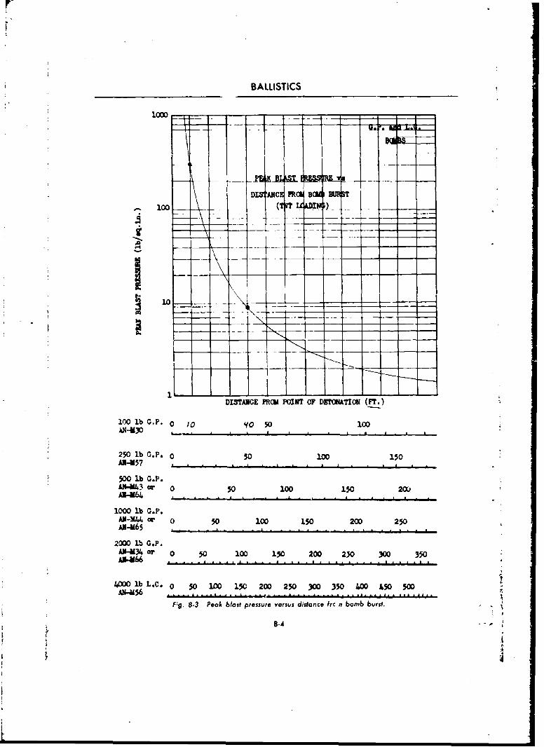
BALLISTICS
1000
100 lb o D.P 0B 10 14 0
4 - - -- -- 1
II
DITANCE FCIL POINT OF DXTCtMATI0 (r.)
lO0 lb .P, 0 w0 q0 50 100
250 lb G.P. 0 50 100 150'.-357
500 lb G.P.Al-UI43 or 0 0 100 150 20(A"3-64 . . .
1000 lb G.P.AX-X or 0 50 100 150 200 250AN-M65
2000 lb G.P.AIU-34 or 0 50 100 150 200 230 300 350AI-M6..................... .... ..... . ..... ,..i
40ODolbL.C. 0 50 100 150 200 250 300 350 4Wo 50 5WA".56..................
F~g. 8.3 Peoa blast pressure versus distance frc n bomb burst.
' -4
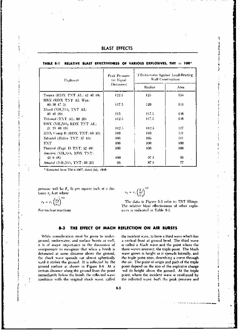
BLAST EFFECTS
TABLE 8-1 RELATIVE BLAST EFFECTIVENESS OF VARIOUS EXPLOSIVES, TNT 100O
Peak PrI'sure I'f 'eet ivezess Againsut Load-Beariuzg
Fy..plo'uvP (at Equal Wall C'otoiruction
Dist anles)Radius Area
Torpex (RDX TNT. AL: 42.40 18) 122.5 125 151;
HHBX (RDX.TNT AL Wax:40,38-1735) 117.5 120 144
Minol (NH "NO TNT AL:
40 40 '20) 115 117.5 138
"Iritonal (TNT AL,: 80 20) 112.3 117.5 138I)HX (NI14N0 3 RI)X TNT AL:
21 21 40 18) 112.5 112.5 127
1it)X ('omp B (itI)X. TNT: 60 -10) 110 110 121
EdMatol (lIlalite TNT: 57 43) 105( 105 III
TNT 100 100 100
Picratol (Expl. D TNT: 52 48) 100 100 100Amatex INIliN()x IDX TNT:
43 9 48) 100 97.5 95
Amatol (NHNO3. TNT: 50 50) 95 87.5 77
Extracted from TM 9-1907, dated July 1948.
pressure will be P, lb per square inch at a dis- =tance r. feet where r: r ,,7. 1
1/3l
r, = r 1 The data in Figure 8-3 refer to TNT fillings.r rt I/ The relative blast effectiveness of other explo-
For nuclear reactions s.,ves is indicated in Table 8-1.
8-3 THE EFFECT OF MACH REFLECTION ON AIR BURSTS
While consideration must be given to under- the incident wavc. to form a third wave which hasground, underwater, and surface bursts as weil, a vertical front at ground level. The third waveit is of major importance in the discussion of is called a Mach wave and the point where theoverpressure to recognize that whcn a bomb is three waves intersect, the triple point. The Machdetonated at some distance above the ground, wave grows in height as it spreads laterally, andthe shock wave spreads out almost sphericaily the triple point rises, describing a curve through
ui.atil it strikes the ground. It is reflected by the the air. The point of origin and path of the tripleground surface as shown in Figure 8-4. At a point depend on the size of the explosive chargecertain disiance along the ground from the point ,nd its height above the ground. At the tripleimmediately below the bomb, the reflected % ave point, where the incident wave is reinforced bycombines with the original shock wave, called the reflected wave, both th peak pressure and
8-5
(~ - .
' = " - i . . . i-
BALLISTICS
MACH REFLECTION
Q..q
Fig. 8-4 Formation of Mach wave and triple point.
impulse are a maximum, and considerably higher eases by almost 50 over that for the same bomb
than that exerted by the original shock wave at detonated at ground level. The area of effective-
* the same distance from the point of explosion. ness is thereby increased by as much as 100O
: As the Mach wave grows in height it absorbs under some conditions. Ballistic data are used
the incident and reflected waves. Ultimately. at to determine the height of burst necessary to
distances very large compared to the height of maximize the horizontal distance at which a
burst, the whole configuration of shocks becomes given impulse can be obtained.The optimum height for an air burst, and the
approximately a single spherical shock wave in- ae.. , amount by which its e•'ectiveness will be in-
tersecding the ground perpenidicular1y, creased depend on the size of bomb, and theUtilizing this phenomenon of Mach reflection strength and height of the target structure. The
makes it possible to increase considerably the use of air burst on some types of targets, such asradius of effectiveness of a bomb. By detonating city areas, also tends to increase the area ofa weapon at the proper height above the ground effectiveness of a blast bomb by reducing thethe maximum radius at which a g,iven pressure shielding effect that buildings and other st,'uc-or impulse is exered can be incrcased in some tures have on one another.
8.4 IMPULSE
As indicated in Figure 8-1, a physical chiarac- approximately equal to one-half the peak pres-teriýtic of a shock wave that is of basic im- sure multiplied by the duration of the positiveportance, is the impulse of the positive phase. phase and is measurcd in units of pound-milli-As a measure of both the intensity of the pressure seconds per square inch. The impulse of anand its duration, it is equal to the area under the expl'sion will be equal at distances that vary aspressure-time curve of the positive phase. It is the two thirds power of the ratio of the weights
8-6
: I
BLAST EFFECTS
I. ~ r- I
1t T
71 --4-
J.1
J IFý.R5 Bas mus vru itacOrmbobbrt
oryed Y ie fteiplefo ,l s rvddmnmmvle fiplerqie
* ~ ~ d J.l-e e qaeic tr eete h m odsryasecfctp fsrcueaeko
9-T-
0'.
BALLISTICS
TABLU 8-2 OVERPRESSURE, DYNAMIC PRESSURE, AND WIND VELOCITY INAIR AT SEA LEVEL
Peak Overpressure Peak Dynamic Pressure j Maximum Wind Velocity(pounds per square inch) (pounds per square inch) (miles per hour)
72 80 1.17050 40 94030 If; 67020 8 47010 2 290
5 0.7 160
2 0.1 70
8-5 DYNAMIC PRESSURE
Although the destructive effects of the blastwave have usually been related to values of thepeak overpressure, there is another qu.antity ofequivalen, importance called the dynamic pres-sure (q = 37pu 2 ). For a great variety of buildingtypes, the degree of blast damage depcndslargely on the drag force associated with thestrong (transient) winds accompanying the pas- O esage of the blast wave. The drag force is in-fluen•,d by certain characteristics (primarily the D Pshape and size) of the structure, and is gener-ally dependent upon impulse.
The dynamic pressure is a function of the wind Ambient
velocity and the density of the air behind the Arrivalshock front Both of these quantities are related Timeto the overpressure under ideal conditions at theshock front (see Par. 8-8). For very strong Fig. 8-6 Variation of overpressure and dynamic
shocks, the dynamic pressure is larger than the pressure with Gimn at a fixed location.
overpressure, but below 69 pounds per squareinch oxerpressure at sea level, the dynamic pres-sure is smaller. Like the peak shock overpressure. rate of pressure decrease behind the shock frontthe peak dyammic pressure decreases with in- is different. This may be seen from Figure 8-6creasing distance from the explosion center, al- which indicates qualitatively how the two pres-though at a greater rate. Some indication of the sures vary in the course of the first second or socorresponding values of peak overpressure, p.,ak following arrival of the shock front. Actually,dynamic pressure, and maximum blast wind the wind velocity (and the dynamic pressure,velocities in air at sea level is given in Table 8-2. will drop to zero at a somewhat later time, due
At a given location, the dynamic pressure largely to the inertia of the moving air but forchanges with time in a manner somewhat simi- purposes of estimating damage the difference islar to the change in the overpressure, but the not significant.
8-8
BLAST EFFECTS
8-6 AIR BLAST LOADING
The hehavior of an object or structure VXf)C5tt can take various forms. For example, the blastto the blast wave front at nuclear explosion inas may deflect structural steel frames, collapse roofs,be considered uinder two main headings. The dish-in walls, shatter panels, and break windows.first is called the loading, i.e., the forces which In general, the damage results from some tvperesult fromn the action of the blast pressure. The of displacement (or distortion ) and the manner
seodis thle itesponse, or distortioni of the strite- in which such displacement can arise as the re-ttarc (lilt to the particular loading. As at general suilt of a nuclear explosion will be examinedrule. rONsponSe maY be taken to be sNfnon% mous below.with danmige since permanent distortion of a For an air burst, the directioni of propagation .
sufficient amowunt wsill impair the risettiness of at of thlt incident blast wave will be perpendicular-trauctinre. Damnage may also arise fromt a oiov- to thec grounnd at ground zero. In the regularWfte ol ijct striking -,It- ground or another ofbject reflection regic-i. the forces exerted upon struc-
which is more or lt-s' Rt-d. Foi example, tWmis- ttucs wili also bave at considerable vertical coin-Wiing st-il ds are dlami a,.ed -,rimna rilv as t li,-\ psonent (,prior to passage of thlt reflected wave).strike the- ground. Fuirther. glass, wood splinters- Cmisequet-iiy, instead of the load'ng beingbricks, pieces of masonry. aaid other objects largely lateral (or sideways) in nature, ax it isbost-ned b\ thc hlast wave and hurled thirough inl thet. Mach region, theri2 will also be an appre-the air forni dustrrt(4itt- itissilt-. Intdirect (lam- ciafde (downwardl force initially, which tends toage~ of tfiesm- t\ pr-s i.. oif course, grea;tly de1petudit canse crushing toward the ground, e.g.. dished-
tPolln ci ret iista miccs. ii i iofs, in add it ion to distortion duc ýo iransla.D i rect daina gi- to strtictutrt-s tdue to itir I-last t mal o rut ion -
8-7 DIFFRAr'.ION LOADING
Whent- thn- front of an air pi..-ssurt- wave strikes is sceen approaching the structure with the di-thc- fiec oi at building, reflection nct-crs. As at rr-ction of inotion perpendicular to the face ofret-silt. tiel1t-ovrp~ressumre buiksill)u rapidly% to at the building exposed] to the blast. In Fig;ure
lI-ast twic- (and venerally se\ve-ral times, that of S-7Tb the waehas just reached its front face.tilt- incitd-mt shuck front. The actuial psressure prcoducing at high overpressure. In Figure 8-7eattam nt-tI is (ltettrttined 1). \iariotis factors such ats fthe blast wav.e has proceeded about half waythc- strength of th- incidi-ut shock ;-d the angle allong the btuiltding,, and in Figure 8-7d it hasliets'eet the tlir-c~tin (if inotion . f the shock r-achecd the back. The pressure on the frontsmiLst- totld thc- face of thme buiiding. As 0- face has d roppetd to some extent .antd it is build-shock front tnnovc. forwaard, the os erpressurt- v inc o on the sitdes its the blast wave diffractson tI the fact- dropys raplid I\ towtartd thfat pro~i ) ced aroundt the st ructuetr. Fi nally. whens as in Figureb\ t1c WA~it wave 'a ithoit reflcktion. A.t the ')-7- thet shock front has passed,. approximately-ani- timev. tilt- air pressuirt- waveSt bitns or tlif- cqital air prt-ssures are exerted onl all tbr wallsfa-~mts arortoti tfilt- strmetmirm- si that tlit- strrtctirt- ;and roofý of tle structure. If thme structure isis t-sent ii a Oliv rldfed by the blast. antI ipproxi - orientt-d at an angle to the blast wav-c, the pres-inately the satne pressu're is exerted on all the %tire would immnediately- be exerted on two factes,stalls and the roof, instead of one, hilt the general behavior would
The t'exelopments, described~ above are illits- he thec sanme as juast described ( Fig-ires 8-7f. ,trated in a simplified form in Figure 8-7. This h, antI] i. Jshows, in plan, a building which is being struck The damnage cauised during the diffraction stageby an air blast (\Ia-h) wsave moving in a honi- swill be determined by the~ magnitude of the load-
zontal direction. In Figure 8-7 the shock front ing and I)% its duration. The loading is related
8-9
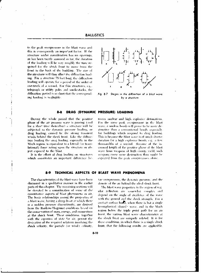
BALLISTICS
to the peak overpressure in the, bla~st wave andthis is conisequiently an iinor'ant factor. if the I L
structure uinder consideration has no openings. 4(if the loading v.1be verv roiighl% the time re- b
quiredl for tile Shock front to move front thefront to the back of the building. The size ofthe structutre will thus affect the diffraction load-ing. For a structure 75 feet long. the diffraction ' lloading will operate for a pecriod of the Order of L
ct~me-tciith of .i scetmnd. For thini structuires. e4.g. 9 h I
telegraph or uitility poles and smonkestacks, thediffraction period is so short that the corresponid- Fig. 8-7 Stojes in the diffraction of a blast wave
*ing loading is negligible, by a structure.
8-8 DRAG (DYNAMIC PRESSURE) LOADING
* ~During the w~hole period thast the positiv e tsveeii nuclear and high explosix detonations.phase of the air prTssire -wave i passing (and For the samne peak- oserpressmirv in tl.e blastfor at shor- time, thereafter) a structure will be wasve. at lnuclear 1 Immi %%ill pros-e to he more dc-
Subjj~p(tedl ro thle (lvrnainic pressutre loading, or structive than a convent ional I mmub. espe-cia'.v
drag loading. caused bNy the strong transient for buildings -which respond to drag loading.%.;nds behind the shock front. Like the diffrac- This is because the blast %%ax-e is of ninch shorteition loading the oirag loading, especial!'. in the duration for a high esplosi%-e bomb, .ei_ a fewNMach region, is equivalent to it lateral ( or trans- th~ousandths Of at second. ti-CcaUNs Of thme i~i-
lational ) force acting upon the structure or oh- creased length of tit(e positi\-v phase of ti' b)lastject expos?d to the blast- XwaVe fromn weapons oif high cnergy ied such
It is the effect of drag loading oil structures w~eapons cause mnore dewtrudion thann might biewhich constitutes an important (liffe-recie be- expec ted from (lthe pk uk usrprt s:,hr& aloine.
8-9 TECHNICAL ASPECTS OF BL.AST WAVE PHENOMENA
The character is ties of the blast w.'avc hav.e been tite overpressure. the d\ ninmic prcssurc, andI the*discussed in at qualitative mnanner in thme earlier deiisitN of the air behind thec ideal shock front.
parts of this chapter. The reinaining sections w~ill The blast wave promperties in the region of reg-be devoted to at consideration of some of tlive u lar reflection are- sonic"-hat eoniplves andquantitativ'e aspects of blast phenomenat in air. depestnd on the angle of incidence of the wsa\vThe has~c relationships a~inong the lpropcitirs of with thle Pround alnd the shock streiigtli. For atat blast v--ve, having at sharp front at which there oiicsufeNt whnhresbti iglis a sui~dden pressuire discontinuity, are- derived hemisphrcal surfaced ,u waen ther is ltht Macsiglfrom the Rankint-Humgoniot conditions bik,"tl on muushrcl(ued wvadi h lcthe conse-vatiofl of mass, enermy, and inomentiun rgion belos'. the triple linin path for an air
at the shock front. These conditionms. togethmer bursit, the variouis b~last wave characteristics at
with the equmationm of staite "or air, permnit the the shock froat are utniquely relaled. It is forderivation of the requiredl relations involving the these%( conditions, in wvhich there is at single shock
shock velocity, the particle (or wind 1 clocity, front. that the following results are applicable.
8-10
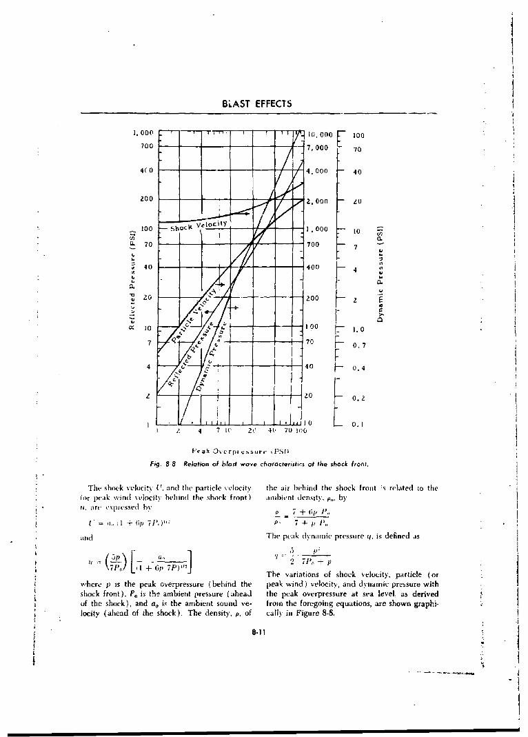
BLAST EFFECTS
r 17.000-~ n 10,000 100700 7,000 70
4(0 - 4,000 40
zoo z,oo zo
100 5oc l velocity 1 '000 10( 70 • - 700 -
7
40 -- 400 4
C, t 4
1000 1.0
7 Q W 70 0.7
4 40 - 0.4
SU 0 L 0I z 4 7 It, 20 4- 70 o0o
Peak 0vcrpicssure iPSD
Fig. 8-8 Relation of blasf wave characteristics at the shock front.
The shock velocity 17, and the particle velocity the air behind the shock front :i related to the(or peak wind %eiocitv behind the shock front) ambient density, p.,. by11, arc (xprcssed by P 7 + 61) P..
C "= . I 1+ 61) 7P',)PO P, 4- I1) ',
and The peak d(ynarnic pressure q. is defined as
q - 0 ,2"
(5p-) I 6 P)IIj I?±u 7--P, (1 + 61}7P-L1
' The variations of shock velocity, particle (orwhere p is the peak overpressure (behind the peak wind) velocity, and dynamic pressure withshock front), P0 is the ambient pressure (ahead the peak overpressure at sea level. as derivedof the shock), and ao is the ambient sound ve- from the foregoing equations, are shown graphi-locity (ahead of the shock). The density, p, of cally in Figure 8-8.
8-l1
1-
BALLISTICS
W~hen the blast .vave strikus a surface, such as It can he seen from thiis expression that the valuethat of a structure, at i~ormaI incidence, i-c-. head of 1), approaches 8 1) for large values of the inci-on, the instantaneous valoie of the reflected over-pressure, 1),, is given b,. (dent overpressure ( strong shocks ) arnd tends
p,=2 7J1.+ p) towardl 2p for smnall overpressures (-weak shocks)71' + (see Figure S-S~
8.10 ALTITUDE CORRECTIONS
The foregoing equations apply to a strictly
homuogefleous atmosphere, that -is, where am'- U.) ~hient pressure and tenrperature at the burst point whbere the p's refer to the respective overpres-and target are' thet same for all casus. If the am- sures at a given distance. The corrected valueslhient conditions are markedIv different for a 0' distance for a specified pressure are thenspecified explosion, as compared .vith those in given bythe reference explosion, then corrve Ion factors I\~mnust he applied. The general relationships w.hich d (W)"'
take into account the possibility that the abso- anfoariltmerpstiehsedaiolute temperature, T, and ambient pressure, P tteaporae cld'itebare not the same ats T,, and P_, respeetiveNy, ini a .
reference (1-kiloton ) explosion, are as follows. r it(L~ (3For thc overpressure, J \T
8-11 BLAST EFFECTS FROM NUCLEAR WEAPONS
Because the most severe blast effects on per- suit of atomic detonations, such effects w.ill besonnel. equipment, and structures come as a re- illustrated for atomic wveapons.
8-11.1 PERSONNEL gireund by the higii winds accompany-irg the
Personnel can be injured by blast in two ways. detonatiun. F'or instai,ce. a 5 psi overpressure
Primary blast injuries resulting fromn thle direct isacmnedbwn. utupo10mhactin o th blat oerpessres n te hman peak velocity. Secondary blast injuries are simi-
lar in effect to those ch.p to mechanical accidentsbody. and st'condarv injuries resultinq from flv-ing decbris. It requires approximmately 100 psi or blast fromn highi e.:plosive dletonations.
overpressure to cause significant primnary injury. 8.12 MLTR EQIENO)verpressumres of this magnitude are not experi-enced even at ground zero front aim ,ir burst All types of equipment c.-n he damaged bywveapon an(l at verv short distances, fromi grounrd blast if the pf ak overpres-sures are hi~gh enough.zero fromn sur acet hurst weapons. Therefore. pii- Wheeled vehicle dameage consists of frame dlis-muary blast injuirie's are not significaint from the tc-rtion. and wheel, body, and engine damage.point of view of personnel casualties. Secondary The rupture of fuel tanks may cause fire to oc-blast injuries are cauised principally by collapsing cur. Overturning contributes to the damage.buildings and debris oi eq~uipent flung about Armored vehicles are very resistant to blast darn,by the hlast, or by the persons being picked up age. However, even these vehicles ma% beanu hurled against statiornrv objects or the damaged in the areas of very high peak manner
8-12
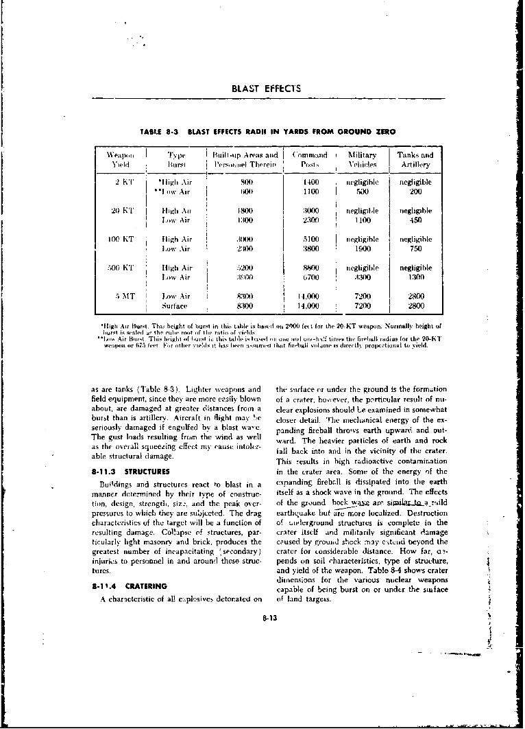
BLAST EFFECTS
TABLE 8.3 BLAST EFFECTS RADII IN YARDS FROM GROUND ZERO
P4,oi I p uil i-tip Arvas and ('omnaiad NtMilitary Tanks andYil Buirst l'ers u iniel The'rcivI Post,i Vehldes Artillery
2 KT 'lligli Air 800 1400 negligible negligible** wAir j 04) 1100 I 50 200
20 XT I High Aii 1800 3 .000 negligible negligible
Low Air i13o0 2300 1100 450
W KT lighAir 23000 50 elgbe ngiil
J~wAir :8010 5
LwAir3-3010
Air 83014,000 72200 20
Surface 8300 14,000 70 8
'Itigh Air ltursI. Thi, height of burst in thi6i tableP is b8as1Vd on 2000O fet for the 20-KT weapon. Normally height ofburst i1 sealed Ihnr.iube root of the rto(fvie!ds
.., - Air Hortri This hvighi of burst iii thisi tatblr is Imss.. (i *'lone and1 ooi-hatf times the fireball radius for the 20-KTweapon or 6l75 feet -For ý,i her % je'il it lhas been aosu'nued that firefiali volume is direetly proportional to Yield.
as re ank jale -3 Lighter weapons and the stirface cr under the ground is the formationfied euipent sicethey' are more easily blown of a crater; ho.'.ever, the pnrticular result of nu-abou, ae daage atgreater distances from a clear explosions should Le examined in somewhatburt tanis rtlley.Aircraft in flight may 'Jie closer detail. The mechanical energy of the ex-serouly amgedifengulfed by a blast wa-c. panding fireball throws earth upwar6 and out-Thegus ladsreultngfrom the wind as well ward. The heavier particles of earth and rock
abhe otrctuall damaeirg effc. ycusnor fall back into and in the vicinity of the crater.
8-13 STRUCTURES in the crater area. Some of the energy )f thc
Buildings and structures rcact to blast in a expanding fireb.Al is dissipated into the earthmanner determined by their type of construe- itself as a shock wave in the ground. The effectslion, design, strengtht, siz_2, and the peak over- of the ground hock wa~ ar jd.tarslpressures to which they are subjccted. The drag earthquake but -are more localized. Destructioncharacteristics of the target will be a function of of ut).nlerground structures is completc in theresulting damage. Gol!apse of structures, par- crater itself arid militarily significant d4amageticularly light masonry and brick, produces the caused by grouoad shock may cxt~tid beyond thegreatest number of incapacitating 'secondary) crater for considerable distance. How far, ct,-injurieýs to personnel in and around these struc- pends on soil characteristics, type of structure,tures. and yield of the weapon. Table 8-4 shows crater
dimensions for (lhe various nuclear weapons8-11.4 CRATERING capable of being burst on or under the swi ace
A characteristic of Alt exýplosive!. detorpated on of land targets.
8-13
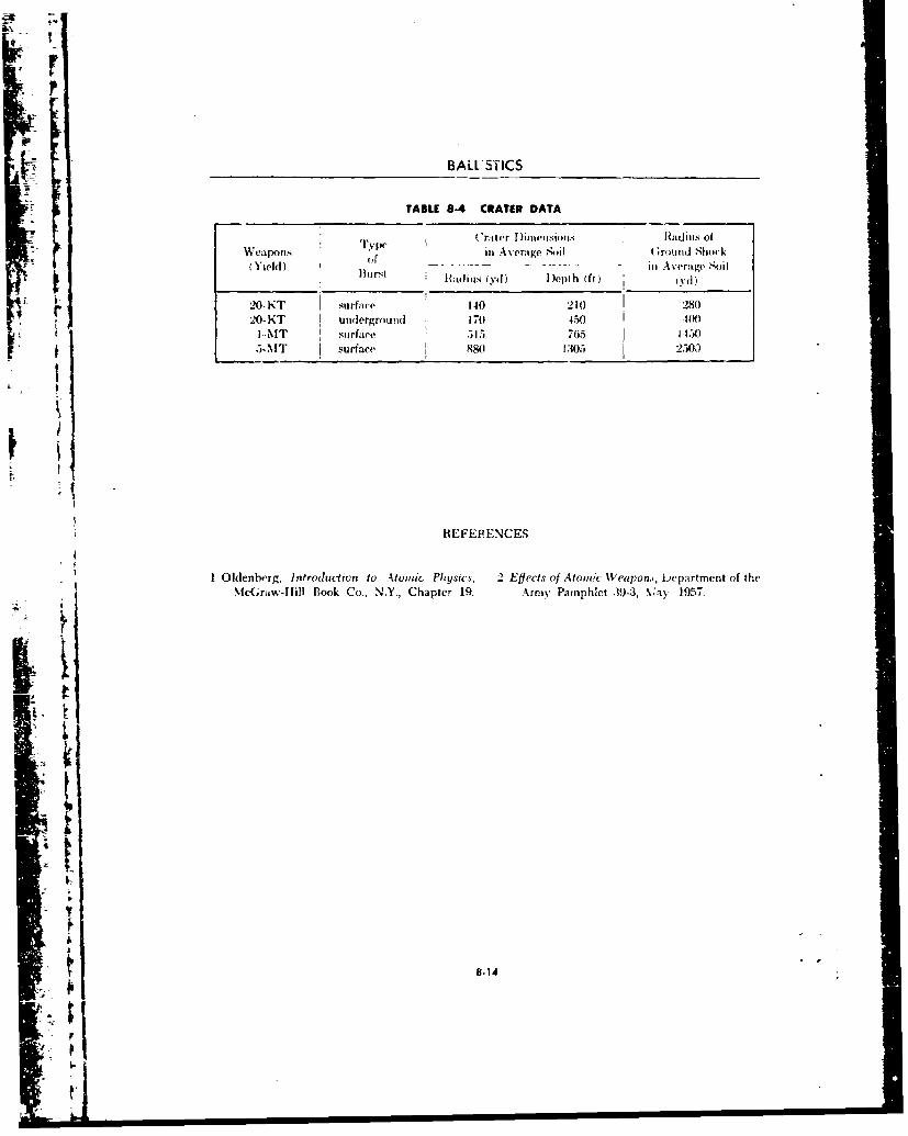
BALL'STICS
TABLE 8-4 CRATER DATA
Wea .ype ( 'raler Tinii,,,Iiotls Radius ofWeapons oanI -rage ini (Ground Shock
+Yield) Hurst -[ladils (y.d) D)epth (fl) 'I 3 rd)
r20-KT surface 140 210( 28020-KT underground 170 4.50 J 00
I.4lT sutrface 515 765 1-1505-MT surface S80 1305 2503
I*t
'1
HEFEF ENCES
1 Oldenberg, Introduction to A.tomic Physics, 2 Effects of Atomic Weapon,, bepartment of theMcGraw-Hill Book Co., N.Y., Chapter 19. Army Pamphlet .39-3, ,ay 1957.
i i -
I -i
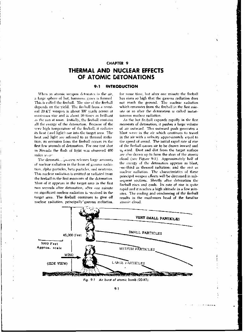
CHAPTER 9
THERMAL AND NUCLEAR EFFECTSOF ATOMIC DETONATIONS
9-1 INTRODUCTION
XVhcn an atomic weapoal d(ltonat(s ini the air, for some time, but after one minute the fireballa large sphere of hot, lumiumnuis gases in formed. has risen so high that the gamma radiation doesThis is callcd the fireball. The size of the fireball not reach the ground. The nuclear radiationdepends on the yield. The firball from a nomi- which emanates from the fireball in the first min-nal 20-KT weapon is about .30C yards across at ute or so after the detonation is called instan.inaxinuum size and is about :30 times as brilliant taneous nuclear radiation.as tile sun at noon. Initially, the fireball contains As the hot fir,.ball expands rapidly in the firstall the energy of the detonation. Because of the moments of detonation, it pushes a large volumevery high temperature of the fireball, it radiates of air outward. This outward push generates aits heat (and light) out into the target area. The blast wave in the air which continues to travelheat and liglNt are referred to as thermal radia in the air with a velocity approximately equal totion; its emission from the fireball occurs in the the speed of sound. The initial rapid rate of risefirst few seconds of detonation. For one test shot of the fireball causes air to be drawn inward andin Nevada the flash of light was observed 400 u,..vard. Dust and dirt from the target surfacemiles a'a' are akso drawn up to form the stem of the atomic
The detonatiu... Vweess releases large amiottits cloud (see Figure 9-1). Approximately half of
of nuclear radiation in the form of gaimnma radia- the energy of the detonation appears as blast;tio•, alpha particles, beta pau tides. and neutrons. ,,ne-third as thermal radiation; and the rest as
i l raclar radiation. The characteristics of theseThis nuclear radiation is emitted or radiated trom principal weapon effects will be discussed in sub-the fireball irn the first moments of the detonation, peuncip ons Shortsly fer detonation thesequent sections. Shortly .4fter detonation the%lost of it appears in the target area in the first fireball rises and cools. Its rate of rise is quitetwo seconds after detonation; after one minute rapid and it reaches a high altitude in a few min-
no significant nuclear radiation is -eceived in the otes. The cooling and condensing of the fireballtarget area. The fireball continues to give off results in the musbroom head of the familiar
nmclear radiation. pr.ncipally'gamma radiation. atomi" cloud.
45,000 Feet ;, MALL PARTICLES
50 eetApprox. scale [DUMP "1CE.
(SIDE VIEW -kGPATICLES
Fig. 9-1 Air burst of atomic bomb (20-KT).
9-1
r
BALLISTICS
9-2 UNDERGROUND BURST
When an atomic weapon is detonated below by the ground. The soil which absorbs the nu-the earth's surface, the expansion of the firehall clear radiation is thrown upward and outward.imparts to the surrounding earth a force upward When it falls back to the ground it contaminatesand outward. A large volume of the earth is the area with residual radioactivity. From anthrown out, leaving a crater. Some of the earth underground burst, then, there is in the targetfalls back into and around the crater. The fire- area no signiF.,ant thermal radiation, greatly re-ball vents tip through the ground; however, by duced blast effects, cratering, and no instan-the time it comes up through the surface, the taneous nuclear radiation.fireball has given tip most of its mechanical shock When the earth in the vicinity of an under-energy to the ground in the formation of a crater. ground burst is thrown upward, it produces aTherefore, air blast resulting from an under- column of characteristic appearance. The heav-ground burst is very much less than from an- air ier particles in the column fall back to earth and
burst. Except for a relatively weak flash that produce a concentric cloud of dust which ex-appears when the fireball vents the surface, al- pands outward from the burst point. This cloudis called the base surge. The finer dust particlesmost all the heat and light (thermal radiation of the column remain suspended in the air asis released into the ground in an underground a cloud for some time before eventually fallingburst. Hence, above ground, thermal effects may to earth. The atomic cloud from an undergroundbe small or negligible. burst does not rise as high as the cloud from an
The nuclear radiation products released by the air burst; moreover, it is colored by the fine par-dutowation process are entrapped or absorbed ticles of soil entrapped in it.
9-3 SURFACE BURST
"The characteristics of a land surface burst are, radiation frcm a surface burst weapon arrivesin general, intermediate between those of an air in the target at very acute angles of incidenceburst and an undergrouad burst. Consider first and minor terrain irregularities, buildings, anda contact surface burst on land, Since the fire- even equipment provide effective shielding.ball, in a surface burst, forms above the ground, The instantanecous nuclear radiation emanatingits rapid expansion generates a blast wave. How- from the fireball of a surface burst seapon isever, some of the mechanical energy of the ex- essentiallv the same as from an air burst weaponpanding fireball is transmitted to the earth undec of the same yield. However, since the freballthe fireball so that air blast from a surface burstdiffers from air blast from an air burst. Since expands against the earth's surface, a consider-
the weapon detonates close to the earth, the air .;'91e portion of the earth tinder the detonation isblast is very strong near the burst point but the vaporized and irradiated. This vaporized irradi-blast pressur(-s fall off more rapidly with increas- ated earth is drawn up by the rising fireball. Theing distances from bui'st point. Some cratering, combination of vaporization of a portion of thehowever, will be accomplished. A 20-KT yield earth's surface and the scooping effect of the ex-bomb detonated on the surface would produce a panding fireball produces a crater, similar to butcrater about 75 feet deep and 100 yards in di- smaller in size than the crater from an under-ameter. ground burst. The heavier particles of rock and
The thermal characteristics of a surface burst soil thrown out by a surface burst. will fall backare essentially the same as for an air burst, i.e., around the burst area. Since the soil has beenjust about as much heat and light are radiated in irradiated it will contribute to residual radioeach case for weapons of the same yield. The activity in the area. The vaporized earth drawnarea of effectiveness of thermal radiation in a up into the fireball will condense when the fire-target area is less from a surface burst than from ball cools; fall to earth downwind, producingart air burst. This is due to the fact that thermal residual radioactivity in the area of fallout.
9-2

THERMAL AND NUCLEAR EFFECTS
9-4 BURSTS IN OR OVER WATER
When an atomic weapon is burst in the air radiactivity (fallout). The base surge con-over water, the blast, thermal radiation, and in- tr;butus to the residual radioactive contamination.stantaneoius nuclear radiation are csentially the If the fa!lout and base surge occur over largesame as for an air burst over land. volumes (if water, the residual radioactive con-
When an atomic weapon is detonated under tamination is soon diluted and dissipated. If thethe surface of a body of water, the column underwater burst occurs in a harbor or nearthrown upward consists of water, or if the under- enough to shore, the fallout may occur over landwater burs' occurs in shallow water, earth from which would cause more conce!ntrated contami-the bottom. The column of water falling back nation and would remain for longer periods.onto the surface produces a base surge of mist WVhen an atomic weapon detonates at or nearand spray. Some of the energy of the fireball as the surface of water, the thermal instantaneousit expands under water is transmitted to the nuclear radiation and blast effects will be essen-wtater and is propagated outward as water shock those )f a land surface burst. However,tially toeo adsraebrt oee,and water waves on the surface. There is noappreciable thermal or instantaneous nuclear some oi the mechanical energy of the expanding
radiation from an underwater burst, and air blast fireball will generate water waves and under-is less than from an air burst. The water, thrown water shock. No crater will forim unless the
upward in the column, is irradiated and entraps water is shallow. A large volume of water will
fission fragments. When this water falls back to be vaporized and drawn up into the cloud. Whenthe surface, it contamiuates the area with residual this condenses, it will be deposited as fallout.
9-5 CHARACTERISTICS OF THERMAL RADIATION
Most of the flash of light and heat from an duction in intensity is due to absorption of theatomic detonation is cmitted in the first second radiation by particles of dust, smoke, and hazeof the detonation although some continues to be in the air. The burning that might result from ant-mitted as long as the ball of fire is visible. As has atomic detonation, then, will be less when thebeen mentioned, approximately one-third of the air is hazy than if it is clear. A smoke screen,energy liberated in an atomic detonation is in therefore, may be an effective shield in lesseningthe form of heat energy In many cases the in- the effects of toermal radiation from an atomictense flash ot light will be the first warning of an weapon.atomic detonation in the area but the thermal Personnel who are facing in the general direc-rauliation will have already been emitted. The tion of an atomic detonation may experience athermal radiation, like light, travels in straight temporary blindness, called flash blindness. Es-lines and is stolpped by any object or material sentially narmal vision returns in a half hour orwhich can cust a shadow. It has little penetrating less. At night, even personnel facing away frompower. Thus, even light-wkeight clothing may an atomic detonation (eyes open and uncovered)"offer protection from such radiation. may experience flash blindness but it will not
As the thermal radiation travels outward from persist as long as in personnel facing the detona-[ the fireball, it decreases in intensity. This re- tion.
9-6 MECHANISM OF THERMAL RADIATION
Imrnmdiatelv after the ball of fire is formed, phenomena associated with the absorption of theit emits thermal radiation. Because of the verN thermal radiation by the air in front of the ballhigh temperatures, this consists in ultraviolet of fire, the surface temperature undergoes a(short wave length) as well as visible and in- ctn ious change. The temperature of the interiorfrared (long wave length) rays. Due to certain falls steadily, but the surface temperature of the
9-3
f
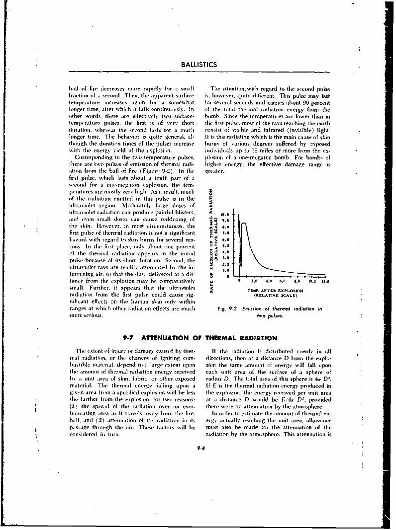
BALLISTICS
hall of fire decreases more rapidly f,)r a small Thie situation.with regard to the second pulsefraction of second. Then, the apparent surface is, however, quite different. This pulse may lasttemperature increases ag'in for a somewhat for several seconds and carries about 99 percentlonger time, after which it falls continuously. In of the total thermal radiation energy from theother words, there are effectively two surface- bomb. Since the temperatures are lower than intemperature pulses. the first is of very short the first pulse, most of the rays reaching the earthduration, whereas the se-zond lasts for a much consist of visible and infrared (invisible) light.longer time. The behavior is quite general, al- It is this radiation which is the main cause of skinthough the duratiin times of the pulses increase burns of various degrees suffered by exposedwith the energy yield of the explosion, individuals up to !2 miles or more from the ex-
Corresponding to the two temperature pulses, plosion of a one-megaton bomb. For bombs ofthere are two pulses of emission of thermal radi- higher energy, the effective damage range isation from the hall of fire (Figur'- 9-2). In the greater.first pulse, which lasts about a tenth part of asecond for a one-megaton explosion, the tem-
peratures are mostly very high. As a result, much z
of the radiation emitted in this pulse is in the -ultraviolet region. M(ocrately large doses of Q
ultraviolet radiation can produce painful blisters, 4 10.0and even small doses can cause reddening of 9the skin. However, in most circumstances, the C 4.0first pulse of thermal radiation is not a significant 7.0hazard with regard to skin burns for several rea- 6.0sons In the first place, only about one percent 01 5.0
of the thermal radiation appears in the initial 0 - 4.0
pulse because of its short duration. Second, the 3.02.0
ultraviolet rays are readily attenuated by the in- 1.0
tervening air, so that the dose delivered at a dis- h 00 0tance from the explosion may be comparatively W 0 2.o 4.0 6.0 8.0 10.0 iZ.0small. Further, it appears that the ultraviolet TI AFTER XPLSONradiation from the first pulse could cause sig- -(RELATIvE SCALE)nificant effects on the human skin only withinranges at which other radiation effects arc much Fig. 9-2 Emission of thermal radiation inmore serious. two pulses.
9-7 ATTENUATION OF THERMAL RADIATION
The extent of injury or damage causcd by ther- If the radiation is distributed cvenly in allnial radiation, or the chances of igniting com- directions, then at a distance D from the explo-bustihle material, depend to a large extent upon sion the sami- amount of energy will fall uponthe amount of thermal radiation energy received each unit area of the surface of a sphere ofI)y it unit area of skin, fabric, or other exposed radius D. The total area of this sphere is 4
w D=.material. The thermal crergy falling upon a If E is the thermal radiation energy produced ingiv,,n area from a specified explosion will be less the explosion, the energy received per unit areathe farther from the explosion, for two reasons: at a distance D %, ould be E, 4f) D2, provided(I ) the spread of the radiation over an ever- there were no attenuation by the atmosphere.iucreasing area as it travels away from the fire- In order to estimate the amount of thermal en-hall; and (2) attenuation of the radiation in its ergy actually reaching the unit area, allowancepassage through the air. These factors will be must also be made for the attenuation of theconsidered in turn. radiation by the atmosphere. This attenuation is
9-A
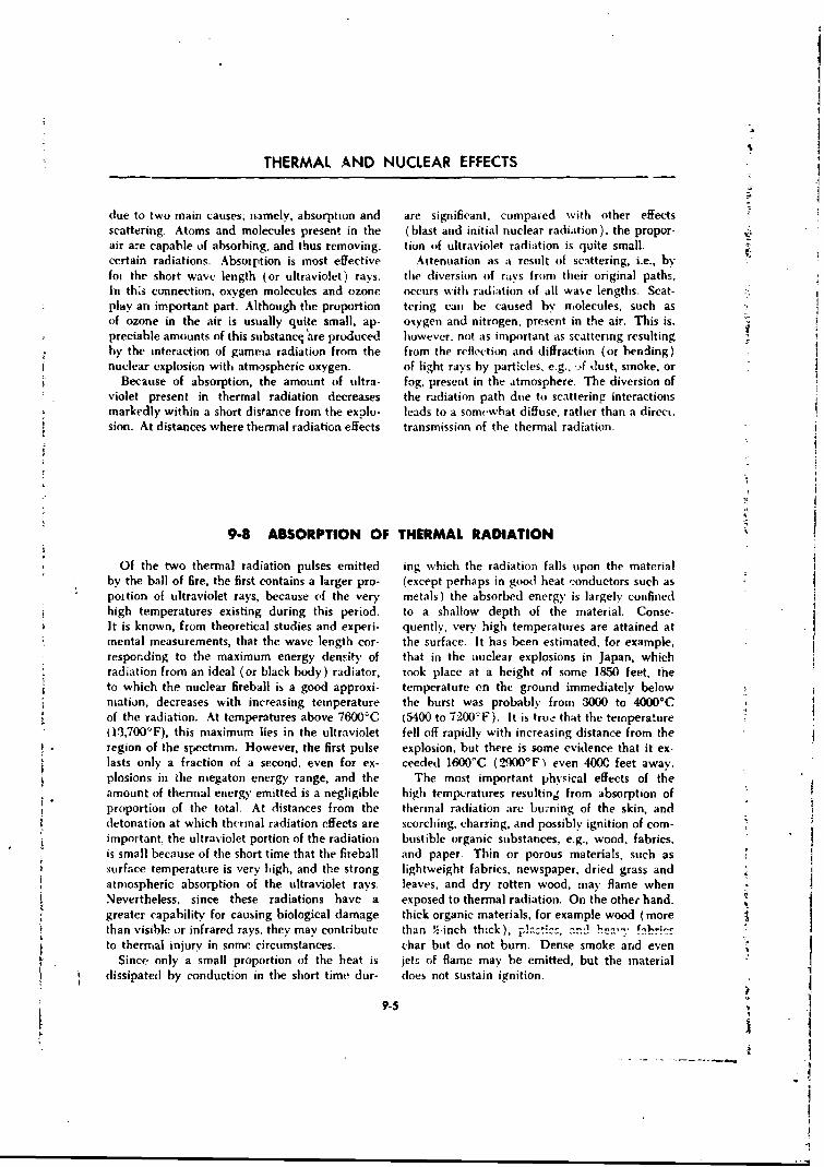
I
"THERMAL AND NUCLEAR EFFECTS
due to two main causes, namely, absorption and are significant, compaied with other effectsscattering. Atoms and molecules present in the (blast and initial nuclear radiation), the propor-air are capable of absorbing, and thus removing, tion of ultraviolet radiation is quite small.certain radiations. Absoiption is most effective Attenuation as a result of scattering, i.e., byfoi the short wave length (or ultraviolet) rays. the diversion of rays from their original paths,In th:s connection, oxygen molecules and ozone occurs with radiation of all wase lengths. Scat-play an important part. Although the proportion tering can be caused by molecules, such asof ozone in the air is usually quite small, ap- oxygen and nitrogen, present in the air. This is,preciable amounts of this suibstancq are produced however, not as important as scattering resultingby the interaction of gamria radiation from the from the reflection and diffraction (or bending)nuclear explosion with atmospheric oxygen. of light rays by particles, e.g., ,.f dust, smoke, or
Because of absorption, the amount of ultra- fog, present in the atmosphere. The diversion of"violet present in thermal radiation decreases the radiation path due to scattering interactionsmarkedly within a short distance from the explo- leads to a some'what diffuse, rather than a direct.sion. At distances where thermal radiation effects transmission of the thermal radiation.
9-8 ABSORPTION OF THERMAL RADIATION
Of the two thermal radiation pulses emitted ing which the radiation falls upon the materialby the ball of fire, the first contains a larger pro- (except perhaps in good heat conductors such aspoition of ultraviolet rays, because of the very metals) the absorbed energy is largely confinedhigh temperatures existing during this period, to a shallow depth of the material. Conse-It is known, from theoretical studies and experi- quently, very high temperatures are attained at
. mental measurements, that the wave length cor- the surface. It has been estimated, for example,responding to the maximum energy density of that in the nuclear explosions in Japan, whichradiation from an ideal (or black body) radiator, took place at a height of some 1850 feet, theto which the nuclear fireball is a good approxi- temperature on the ground immediately belowniation, decreases with increasing temperature the burst was probably from 3000 to 4000°Cof the radiation. At temperatures above 76000C (5400 to 72002-F). It is true that the temperaturei13,700'F), this maximum lies in the ultraviolet fell off rapidly with increasing distance from theregion of the spectrum. However, the first pulse explosion, but there is some evidence that it ex-lasts only a fraction of a second, even for ex- ceeded 1600'C (2900°F even 4000 feet away.plosions in the megaton energy range, and the The most important physical effects of the
* amount of thermal energy emitted is a negligible high temperatures resulting from absorption ofproportion of the total. At distances from the thermal radiation are burning of the skin, anddetonation at which thermal radiation effects are scorching, charring, and possibly ignition of com-important. the ultraviolet portion of the radiation bustible organic substances, e.g., wood, fabrics,is small because of the short time that the fireball and paper. Thin or porous materials, such assurface temperature is very high, and the strong lightweight fabrics, newspaper, dried grass andatmospheric absorption of the ultraviolet rays. leaves, and dry rotten wood, may flame whenNevertheless, since these radiations have a exposed to thermal radiation. On the other hand.greater capability for causing biological damage thick organic materials, for example wood (more 3than visible or infrared rays, they may contribute than !'-inch thick), p!• ..-... i , ...'to therrmial injury in some circumstances. char but do not burn. Dense smoke and even
.Since only a small proportion of the beat is jets- of flame may be emitted, but the materialdissipated by conduction in the short time dur- does not sustain ignition.
S9-5
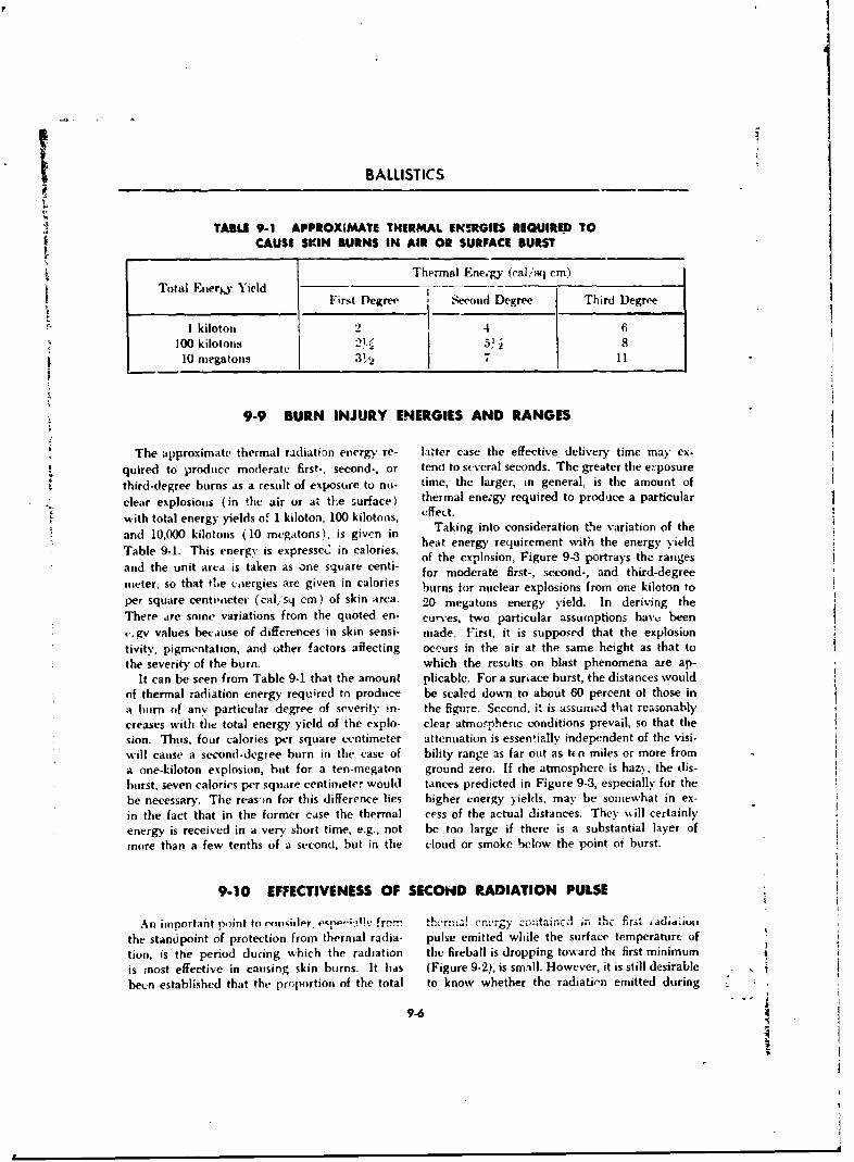
* a
BALLISTICS
TABLE 9-1 APPROXIMATE THERMAL EKNRGIES RIQUIRED TOCAUSE SKIN BURNS IN AIR OR SURFACE BURST
Thermal Ene.'gy (calisq cm)Total ,Eer Yield I lFirtst Degree S'teconid Degree Third Degree
1 kiloton 4 6100 kilotons 2' . 5' ., 8
10 megatons 3P'/ 11
9-9 BURN INJURY ENERGIES AND RANGES
The approximate thermal radiation energy re- latter case the effective delivery time may ex-quired to produce moderate first-, second-, or tend to several seconds. The greater the e::posure
third-degree burns as a result of exposure to nu- time, the larger, in general, is the amount of
clear explosions (in the air or at the surface) thermal ene;gy required to produce a particular
"with total energy yields of 1 kiloton, 100 kilotons, effect.and is in Taking into consideration tie variation of the
10Ta 0009ki.oTons (10rg m egton alories, heat energy requirement with the energy yieldTable 9-1. This energy is expressetd in calories, of the explosion, Figure 9-3 portrays the rangesand the unit area is taken as one square centi- for moderate first-, second-, and third-degreemeter, so that tLe coergies are given in calories burns for nuclear explosions from one kiloton toper square centiueter (calsq cm) of skin area. 20 megatons energy yield. In deriving the
There are some variations from the quoted en- curves, two particular assumptions have, been
,.gy values because of differences in skin sensi- made. First, it is supposed that the explosiontivity, pigmentation, and other factors aflecting occurs in the air at the same height as that tothe severity of the burn. which the results on blast phenomena are ap-
It can be seen from Table 9-1 that the amount plicable. For a surlace burst, the distances wouldof thermal radiation energy required to produce be scaled down to about 60 percent ot those ina burn of any particular degree of severity in- the figure. Second, it is assumed that reasonablycreases with the total energy yield of the explo- clear atmorpheric conditions prevail, so that thesion. Thus. four calories per square centimeter attenuation is essentially independent of the visi-will cause a second-degree burn in the case of bility range as far out as ten miles or more froma one-kiloton explosion, but for a ten-megaton ground zero, If rhe atmosphere is hazN, the dis-burst, ;even calories per square centimeter would tances predicted in Figure 9-3, especially for thebe necessary. The reas'mn for this difference lies higher energy yields, may be somnewhat in ex-in the fact that in the former case the thermal cess of the actual distances. They will certainlyenergy is received in a very short time, e.g., not be too large if there is a substantial layer ofmore than a few tenths of a second,. but in the cloud or smoke below the point ot burst.
9-10 EFFECTIVENESS OF SECOND RADIATION PULSE
An important point to ronider e•r','' .br'c'.-r. th'r:., ergy cita th. first adAdiuu
the standpoint of protection from thermal radia- pulse emitted while the surface temperature oflion, is the period during which the radiation the fireball is dropping toward th( first minimumis most effective in causing skin burns. It has (Figure 9-2), is small. However, it is still desirablebeen established that the proportion of the total to know whether the radiati,-n emitted during
9-6
21
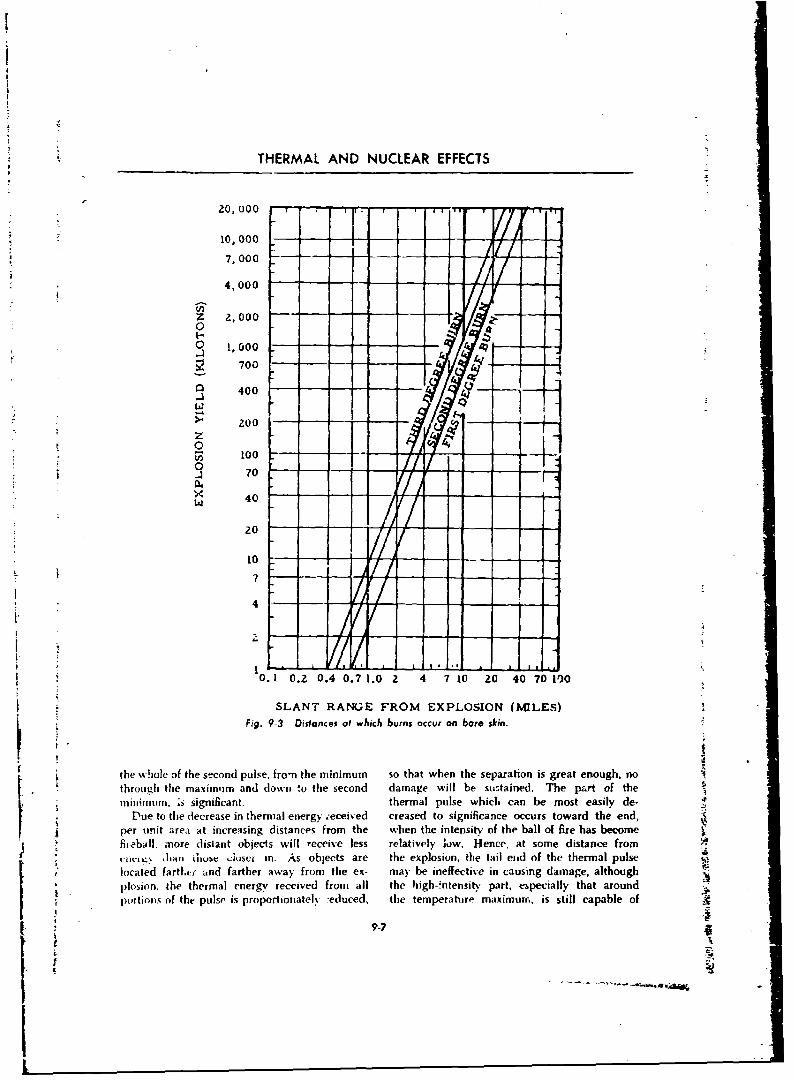
THERMAL AND NUCLEAR EFFECTS
r zo~~~~2, Uo 0'0'"i / '1 1 "
10,000 - - '
7,000 - - - -
4,000 - - - -
z 2,000 .o a
o 1,r000 -
S700
S 400 :7
W 200 . . ..
o100 - - * --
0 70 - - - -LJ 40 -- -
2 /
10 0.2 0.4 0.71.02 10204070 10
SLANT RANGE FROM EXPLOSION (MILES)Fig. 9-3 Distances at which burns occur on bore skin.
the,.vhole of the second pulse, fro-n the minimum so that when the separation is great enough, nothrough the maximum and down to the second damage will be stistained. The part of themari'munu. ;s significant. thermal pulse which can be most easily de-
Due to the decrease in thermal energy .-eceived creased to significance occurs toward the' end,per unit area at increasing distances from the when the intensity of the ball of fire ha" become)flieba.ll. more distant objects will receive less relatively iow. Hence, at some distance from
h imn iiuse Jusci- in. As objects are the explosion, the tail enid of the thermal pulselcated fartl.ui- and farther away from the ex- may he ineffective in causing damage, althoughplosion. the thermal energy received from all the high-mntensity part, especially that around
9.7
"II
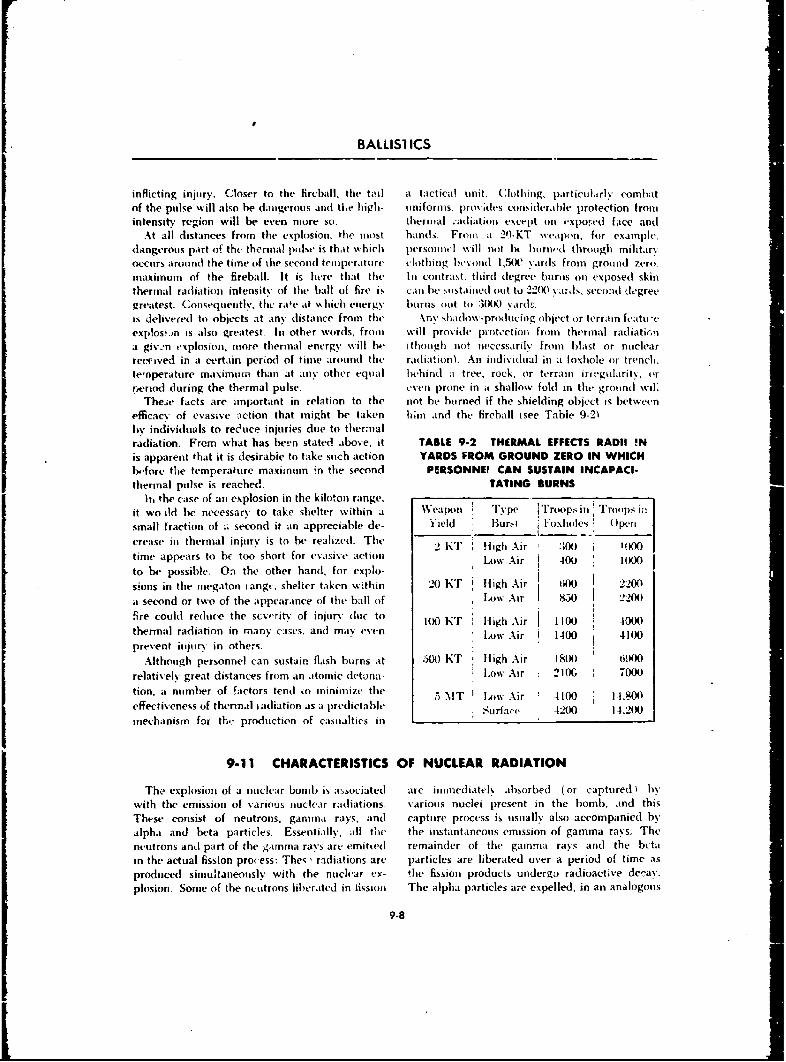
FI
BALLISI ICS
inflicting injury. Closer to the fireball, the tiul a tactical unit. Clothing, particilarly combat
of the pulse will also be dangerous and tlhe high- uniformis. provides tnmsiderable protection fromintensity region will be even more so. theinial ;adiation except on expoted face and
At all distances from the explosion, the most hands. From a 20-KT wealpon, for example,
dangerous part of the thermal pulse is that which personnel will not hI burn.d through militarxoccurs arond the time of the second temperature clothing besumd 1,50KC ards from ground zero.
maximum of the fireball. It is here that the In contrast, third degree burns on exposed skin
thermal radiation intensity of the ball of fire is can he sustained out to 2200 airds. secn-id degree
greatest. Consequently, the rafe at ,v hich etnergy burns out to 3WO .tards.
is delivered to objects at any distance from the Any shadow-produci0ug object or terrain featuceexp!osvin is also greatest. In other words, from will provide pruotction from thermal radiatir,a givmn explosion, more thermal energy %%ill he thoughl not necessarily from blast or nuclearreefived in a certain period of time around the radiation) An individual in a foxhole or trench.temnperature maximum than at any other equal behind a tree, rock, or terrain irwugolaritv, or
r,eriod during the thermal pulse. even prone in a shallow fold in the ground wil'The.ie facts are important in relation to the not he horned if the shielding object is between
efficacy of evasive action that might be taken him and the fireball (.see Table 9-21by individuals to reeuce injuries due to thermalradiation. From what has been stated above, it TABLE 9-2 THERMAL EFFECTS RADII !Nis apparent that it is desirable to take such action YARDS FROM GROUND ZERO IN WHICH
before the temperanure maximum in the second PERSONNEI CAN SUSTAIN INCAPACI-thermal pulse is reached. TATING BURNS
Ih, the case of an explosion in the kiloton range.it wo l!d be necessary to take shelter within a WVeapon Type Troops in Troops in
small fraction of i second it an appreciable de- Yield Burm.- Foxholes Open
crease in thermal injury is to be realized. Thetime appears to be too short for evasive action .l2K Hv Air 300 I00
to be possible. On the other hand, for explo-
sions in the megaton rangi., shelier taken within 20 KT i High Air (M0 220
a second or two of the appearance of the ball of IAuw Air 80 "2200
ire could reduce the scvprity of injurv duh to 100 KT High Air 1100 4000
thermal radiation in many cases, and may even Low Air 1400 4100
prevent injurv in other,;.
Although personnel can sustain flash burns at JAR) KT Iligh Air 1800 6900
relatively great distances from an atomic detona- Low Air 210G 7000
tion. a number of factors tend to minimize the ; %IT I low Air !4100 14.80
effectiveness of thermal radiation as a predictable Surface 4200 14.200
mechanism for the production of casualties in
9-11 CHARACTERISTICS OF NUCLEAR RADIATION
The explosion of a nuclear bomb is associated are immediately absorbed (or captured) bywith the emission of various nuclear radiations. various nuclei present in the bomb, and this
These consist of neutrons, gamnuna rays, and capture process is usually also accompanied by
alpha and beta particles. Essentially. all the the instantaneous emission of gamma rays. The
neutrons anti part of the gamma rays are emitted remainder of the gaminma rays and the beta
in the actual fission pro ess: The; , radiations are particles are liberated over a period of time as
produced simultaneously with the nuclear ex- !he fission products undergo radioactive decay.
plosion. Some of the neutrons liberated in lission The alpha particles are expelled, in an analogous
9-8
THERMAL AN~D NUCLEAR EFFECTS
ina 00cr, ats it resinlt ofe1 (Iuca. V lit' i~i tra fiiii iii Lirvegr than tihiat givyen abhove. Hc OWL 5cr. at the(otr pluton Iium) witicit hads escaped fission ill sailne tinme. there is- an mni r-'ase in the rate itthe bointh. which thte cloud rises'. Similarly, for a hoiub of
'I he initial iche ar ri. 1 it n0.s i, 'e anll% is'er enr .the eifeciet j' i stance k less, hotidiefinred is (hiat enii tted fro nht bolithe !I iall of NOt Also is lit ri-te (if ascent of the ciown& Thefire and the atomnic cloud ,%ithin the first toinimtc peril d to.ci "h ich the jnit ial nuiiciea r radiiatinofafter tw K' xpjlos imm. It i mcliiutis neulltrons and -\ Icods ina i vonii)S'iii,. tiV h e tatken to be approsi-gainnma ra%'Vs g i vc oI ff ailmost in I nita mci tinsl it,, as atihi the Naini (% iaimclv moen(a iinfu t. i rrespec~i e
well :S gamma lit a em SS'iit tetd li tihe ri-dio0,1(1 Se i th he tin'rgv rticatd5 of ti ehu ninth.fi ssiotin prodiuct s ~i the rising eh niild. It shil icih Nk-utritons are then oin lv i oi fiale Nii nuclea rnote'd thait a I t1in1ngin A iph~i Mid b etai 1it rt iceN: irt itai ationun produ ctd 'diri ctl% in tiler mioi 'tl''a rpresent iii the initii l .1 diatiini. the\ hat\-, irut revk tiooS . AlIpn.i partiles It" 1elimn inuclei ) arteI-en cowidsteret. iThis is bectust- the arm' sit .mso ftirimiet. hiut tl!'v\ doi oit trave~l \very far fromteasi i v absoirbeid i that they Will PAtn reach iminre tin1 ' ~ is it iii. Soit Ii of tin' ncu t ril tt5will escalpethnan a tew va rds at oin0t. iromtho'le aoinii nc loo b umt nithe: .. Noiilit be apt iired hv thi \arion sn nelei
Tihi sotin ewha t a rii trarv time periodt of one1 jirtescilt tin the' t ploitni ii gIniinb. Tihose nil iirons
ninn unte for the dun at ion of in itial nuclear r.dia - ablsorb edl h\I ti~s~ionah.l it species ii1a lvead tnt rhetion was oragitiaiiv based upon thle fc1lo in' ng liichratin t otiif imore nentrtons as %\ell is tio theL'onid~titrihItions: _V. ai consequtenlce tif antteinua~tion ii ciiissici; inof gil inii O rtnvs, just is d-(rles n ed aboveliy the air. the effoctive range ouf the Fission for din ordinairy fssioit bininn. In adtitiiton, the
gainii axsan ~ hoefnnthheeistinpr (-aotirc of nucntrtons in nonilissitin -etuetions is
dtncis front a 20.1 i loton e.\ in!s on is very rotn ii l nstt lliv al týcomipamied by gaininma ranxs. It is -seen.two m ies Iiotli(vI words. ,gamma rays omiionat - t herefore. thatt tihe i nit ial iandia tiliNi froini in bombinig from suchi a sou, ce at io altittude of over (%\o i, whichi iiotii fission and] finsiin ( theriinouiciear)miiles cian lie ignoredi. ats far tis tlneir effect at the prmet'ssi's tocunr coi-sist eseintiaiiv oif nieutronseairth's SmnrfaCe is concerned- Thus- whene the andnt gLiminnd rays. Tiie relantive proportions of
atoinimi Cloidm htns reanched it height of two miles. thtese twri radiatioiins niinn het soinne\hat differentthe effects of tin' initial nunciear radiations are thint fur in bonob in which all the vntrferv releanseno lnnger sigunifletnot. Since it takes roingiliv a is dite tom fission. iLut for present purposes themninute for the cloud tin rise this dijstalnce, tine difft'ervi -vinini hle (ll'tregardiedi. Althoutgh theinitial nuclear radiation w.sdefined as that tenh'rg\ mnf tine i nitial ganinna rays and neutrons isemnittedl in the first winmnte after the texplosiotn. only aboiut three percent of the total explosion
The foregoing ,lrgutments are ltaseti inn tlint cinnigs, toitipared with some :3i3 percent appea.-0hiracteristics oif ai 20-kdoton nuCleaf iioin. For ing its thtermaln radiaition. the nitelean rtndiiitionsin bomb of I igher energy, the maximnuin distanc'e can cas mist' cons iden able proportioin of the hombh
* over which the gamnma ray .s are efftvtiv e will be cais-natites.
9.12 INITIAL GAMMA RADIATION
*The gaiinnnna rays 1mnodiced inn fission. and ins instaint of fissionn. and since, in fa~ct, their rate ofa result of ither neutron reactions and nucletar decay is greatest at tine beginning, there will beexcitatino of the borrb mnateinials, all apPear anl itppreciable liberation of gamma radiationwithin a second (or less) after the nuclear ex- front tiuisc radiioisýotCies dnuring the first minuteplosion. For this reason, thv n'.diati-'as fromn after the ~.cplosioi.. In other words, the gammathese sources are knowni as the prompt or instann- ratys einitte'h by the fission products mnaize ataneouE gamma,- rays. sirnificant contribution to the initiail nuclear
The fissioni fragmenmts and maryv of their d'vav radiation. Howvever, since the radioactive derayprodhints are radioactive isotopes which emit process is an continuing (or gradulna) one, spreadgamma radiations. The half lives (T these radio- over a period of time which is long comparedactive species range fromn a mnillionth of a second to that in -which the instantanec..s radiation is(or less) to man%- vears. Nevertheless, since the produnced, the re-unlting gamnna radliatione aredecay of the fissiorn fragments commences at th- referredi to a% the dclayeti gamma rays.
9-9 -
BALLISTICS
The instantaneous gainiia rays a 11( the porin hiand, are i nostlv elinit ted at at later stage in theOf thle dela~ed gammia rays which are incli!Jcd explosion. after the bonib materials hiave vapor'.fl the initial radiation, are iiearlv ciltjil ii i td And expanlded-C to formn i tenuous gas. These
;.onbu hyare- by' ivn qualI fractions radiat ions the s stiffer little or no absorpt ioni he-of the in it ial nuclear radi~t ion transit t 1( froni fo re vminergiu g in to tlit' air. The net resulit is th atthe exploding bornbI. The ins tantIaneou t s gati ti' a tle dela ved Lzaitin ia rays, together with those,ra.Nv arc p~roduce'd almost entirely before the produced hN the radiative capture of neutronsbomb hats comtiple'tely blosso apart. They are,. h% the nitrogen in the atmosphere, contribute
* t ic6refore, st roi giv abisirh-d bt ,:( deni se bombl about it ahuindredl times ats muich ats (io the prom ptmaterial s, andl onl% a sitia I proport ion it ui lls ta m ita rays to the total rad iat ion rece'ivedl at air'mt'rges- Thme deia) ed izaninu ra,6s, Ot the other distanee from an air (or surface) burst.
* 9-13 SOURCES OF NEUTRONS AND IONIZATION CHARACTERISTICS.*l t hotiihm neuitr(ons .i cc mit ia r particles iof Gn~ a I cii-ege. Th e\ ha% e Li irl% blgh spev ds, hlia
appreciabhle. In.m x, wi ere~as iairn~it rayi are the actutalI ( average ) I ista nce the iieiitrotns t ravi 'electroimagne-tit: waves anialogotis ti X-ra~vs. their is rolativel\ large, and so some time elaps.e befiorehariiifii effects on the lIIKI a re im liar in clmair~ic- thte\- reach the ovits ide of the bail of fi re. H1ow-ter like gatoniia rit s, only ver\ large doses oif ever, the I Lay tin the escape- of the promptneim'r'mns inat pisl \ v he (let,'ct(i hi\ tue tuiinan neuttrons is i m-ore than about I hundredth partse-nses. .Neutronis can lpens't~ite a i~t isiderable of at seconi
dlistance through tthe air anmd constitute a hazard Neutrons, being elcrclyneutral particles.that is greater than inight hie expected from the do inot produce ionization or excitation directlysniall fraction iabinit 0.025 percent, of the in their pas, -ige through matter. They can, how-v'5 pliosln eviierý wNinch they earrn, ever, cause ionization to occur indirectly ats a
Essentially, all the neutrons accoilipanvint. a resuilt of their interaieton wyith certain lightnuclear explosion ,ire reese ither iii the fl :si'in nuclei, When a fast neutron collides with thecr fusion process All of the neotittons fromnt the nuceleus (isf at hydrogen atom, for exa rsp~e, thelatter source and] over 9-9 percent (if the fissiion nueitron niuav transfer a large part of its energynci 't rois .. re pri di Ri' alii out jul mcdi atelv-. proli- to that n ii te Is. As it result, the hyd rogen nucleus'It)[ %% itl ii iIts s t hian in mill ionith of it Second iof is friee IfIromi its assoiciate tcelect tin aind movestin' initiatioi of the( explosion. Thi.se are referred off ats a higIi'eneritv proton. Suich at proton istoi as t1 lepr[uiiipt ncunt moos. ( apabl ( ciif producing a coils iti- ablel inuimber uif
1,1 addition. soumex'hit less thani ine per~ent of iiin pairs in its passage through a gas. Thus, the(In' fission nieut rions. ea fhcd thse del as Ci n,-n trons, interaction of :i fast neuitron atwitl i hd roget ii rSri' tiniiittv~Il u1bstquientlI\. Sinc ti'the unujorit\ of wvith an\ suibstaiice cont-Onin g hvd rigen I cani
thewxi It'laved i it' trtil s arc- emiitted xwithin the( ca'Is ionciztiiationt to occuir indirectly. By a sitmnila rfirst ituinmite. how~ei ir. the% cotstit ute p art oif the( tictchanisiin. indi1rect ion izationn, alIthough to atinitialI numclear radihat io n. S ltiii ne uemtrion s are Also- s na 11cr vs teit , results fromt coillisions of fastprou(lti-id b% the( iction of thei ganiuma rays of ni'tutroiis with other livght nuclei, e.g.. carbon.hii gh energv on the nuicle a r bond ni~tu uteria Is. 0\\ -gen, a m I nitroge 'rTeiizto retItnBi t I ies1' iii, i a \cr\ m inor ii t(oitri lilI o i and so fromt the' intte(ract io n of fast neitut rons wvith Ii xlriocan he ignocred ~eti and nitr'igi'n in tissue is the main cause of
AlthtIai:Jgiti' OWPrompt fission net itroni ;1re alt liiilogica I i jnrv by t' vnut ron--ati( tia I I re''a i 'u %% within lestha I a i mi rihonth of Neutiirions in t i'( sliowx and moditera te speedl
at si 'C n d of the vsplos io n, as notedtc ab~ove, thIe, run ges can produiice io n izatiion i 0(1ireetly in otheraure 5 iiuiwhat tlelavt' %l in cicaping froint it teni- ways. Wihen such neuitruns are captured hy, the-virilument of the explodine boinb. This deayv livjhter isotopt' of boron (borom. 10), two electri-a ri xs from thi' ui nwnroi s se itliriyu mi gciilisiow ( AIN lictiarged particles, at blinnIi in ucuiec s lalphatstiflurt-l by the neutrons with the nuclei pre'seint Particle) and at lithiumr nucleus of high e'nergyif) the boiiiil residuiis. As ;P result, tluc ne'itroius tare formed~. Biith o~f these particles can producetrax i's(' a c'omple'x A/igag path before they ioii pairs. Indlirct ioinizationi by neutrons can
9-10
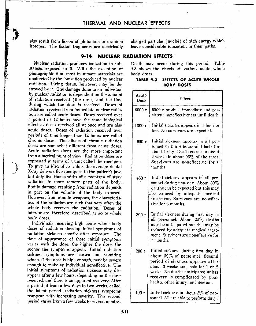
THERMAL AND NUCLEAR EFFECTS
also result from fission of plutonium or uranium charged particles (nuclei) of high energy whichisotopes. The fission fragments are electrically leave considerable ionization in their paths.
9-14 NUCLEAR RADIATION EFFECTSNuclear radiation produces ionization in sub- Death may occur during this period. Table
stances exposed to it. With the exception of 9-3 shows the effects of various acute wholephotographic film, most inanimate materials are body doses.unaffected by the ionization produced by nuclear TABLE 9-3 EFFECTS OF ACUTE WHOLEradiation. Living tissue, however, mav be de- BODY DOSESstroyed by it. The damage done to an individualby nuclear radiation is dependent on the amount Acuteof 'radiation received (the dose) and the time Dose Effectsduring which the dose is received. Doses ofradiation received from immediate nuclear radia- O000 r 5000 r produce immediate and per-tion are called acute doses. Doses received over sistent noneffectiveness until death.a period of 12 hours have the same biologicaleffect as doses received all at once and are also 1000 r Initial sickness appears in 1 hour oracute closes. Doses of radiation received over less. No survivors ,,rc expected.periods of time longer than 12 hours are calledchronic doses. The effects of chronic radiation 650 r Initial sicknes:. appears in all per-doses are somewhat different from acute doses. sounel within 4 hours-aid lasts forAcute radiation doses are the more important about. 1 day. Death ensues in aboutfrom a tactical point of view. Radiation 'doses are 2 weeks in about 95% of the cases.expressed in terms of a unit called the roentgen. Survivors are noneffective for 6To give an idea of its value, the average dental months.X-ray delivers five roentgens to the patient's jaw.but only five thousandths of a roentgen of stray 450 r Initial sickness appears in all per-radiation to more remote parts of the body. sonnel during first day. About 50%Bodily damage resulting from radiation depends deaths can be expected but this mayin part on the volume of the body exposed. be reduced by adequate medicalHowever, from atomic weapons, the characteris- treatment. Survivors are noneffec-tics of the radiation are such that very often the tive for 6 months.whole body receives the radiation. Doses ofinterest are. therefore, described as acute whole 300 r Initial sickness during first day inbody doses. all personnel. About 25% deaths
Individuals receiving high acute whole body may be anticipated but this may be(loses of radiation develop initial symptoms of reduced by adequate medical treat-radiation sickness shortly after exposure. The ment. Survivors are noneffective for
time of appearance of these initial symptoms ? :.onths.varies with the dose; the higher the dose, the
sooner the symptoms appear. Initial radiation 200 r Initial sickness during first day insickness symptoms are nausea and vomiting about 50% of personnel. Secondwhich, if the dose is high enough, may be severe period of sickness appears afterenough tc make an individual noneffective. The about 3 weeks and lasts for 1 or 2initial symptoms of radiation sickness may dis- weeks. No deaths anticipated unlessappear after a few hours, depending on the dose recovery is complicated by poorreceived, and there is an apparent recovery. After health, other injury, or infection.a period of from a few days to two weeks, calledthe latent period. radiation sickness symptoms 100 r Initial sickness in about 2%. of pc'r-reappear with increasing severity. This second sonn. All are able to perform duty.period varies from a few weeks to several months....
9-11

BALLISTICS
9-15 RESIDUAL RADIATION
Residual nuclear radiation, as distinguished tion. About 1% ounces (0.11 pound) of fissionfron instantaneous, is defined as that which is products are formed for each kiloton (or 110
emitred l~ter than one minute after detonation. pounds per megaton) of fission energy yield.,Residu'al- radiation is predominantly gamma. The total radioactivity of the fission products
i( Alpha,'anlbeta particles may also be emitted initially is extremely large, but it falls off at a6,u l ýtl .their' importance is negligible if even the fairly rapid rate as the result of decay,
sirriplestCprecautions are taken against residual At one minute after a nuclear explosion, when'ganuna-raidiation. The atomic cloud is highly the residual nuclear radiation has been postu-"radioactive and may be a hazard to aircraft lated as beginning, the radioactivity from the 1%crews until it is dispersed. The most significant ounces of fission products, from a one-kilotonresidual riadiation from the point of view of explosion, is comparable with that of a hundredtactical fuse of atomic weapons is that which thousand tons of radium. It is seen, therefore,persists';in the target area. that for explosions in the megaton energy range
Fission products constitute a very complex the amount of radioactivity produced is enor-mixture of some 200 different forms (isotopes) of mous. Even though there is a decrease from the35 elemeints. Most of these isotopes are radio- one-minute vclue by a factor of over 6000 by theactive, decaying by the emission of beta particles, end of a day, the radiation intensity may stilland frequently accompanied by gamma radia- be large.
9-16 NEUTRON INDUCED ACTIVITY
The neutrons liberated in the fission process, within a minute or two. The radioactive product
but which are not involved in the propagation of neutron capture by nitrogen is carbon-14; thisof the fission chain, are ultimately captured by emits beta particles of relatively low energy butthe bomb materials through which they must no gamma rays. Nuclear explosions cannot addpass before they can escape; nitrogen (especially) appreciably to the fairly large amount of thisand oxygen in the atmosphere, and variour isotope already present in nature, and so the radi-.elements present in the earth's surface. As a ations from carbon-14 are a negligible hazard.result of capturing neutrons many substances An important contribution to the residualbecome radioactive. They, consequently, emit nuclear radiation can arise from the activitybeta particles, frequently accompanied by gamma induced by neutron capture in certain elementsradiation, over anextended period of time follow- in the soil. The one which probably deservesing the explosion. Such neutron-induced activity, most attention is sodium. Although this is pres-therefore, is part of the residual nuclear radiation. ent only to a small extent in average soils, the
The activity induced in the bomb materials is amount of radioactive sodium-24 formed bvhighly vwriable, since it is greatly dependent neutron capture can be appreciable. This isotopeupon the design or structural characteristics of has a half life of 14.8 hours and emits both betathe weapon. Any radioactive isotopes produced particles, and, more important, gamma rays ofby neutron capture in the bomb residues will relatively high energy. In each act of decay ofremain associated with the fission products. sodium-24, there are produced two gamma rav
When neutrons are captured by oxygen and photons, with energies of 1.4 and 2.8 Mev, respec.nitrogen nuclei present In the atmosphere, the tively. The mean energy per photon from fissionresulting activity is of little or no significance products Is 0,7 Mev, although gamma rays ofas far as the residual radiation is concerned, higher energy are emitted in the early stages,Oxygen, for example, interacts to a slight extent Another source of induced activity is manga.with fast neutrons, but the product, an isotope nese which, being an element essential for plantof nitrogen, ,ns a half life of only seven seconds, growth, is found in most soils even though inIt will thus undergo almost complete decay small proportions. As a result of neutron capture,
9.12I
THERMAL AND NUCLEAR EFFECTS
the radioisotope inanganese-56, with a half life (sodium chloride) in sea water, can be sources ofof 2.6 hours, iý fonned. Upon decay, it gives off consideroble induced activity. The sodium pro-severai gamma rays of high energy in addition to duces sodium-24, as already mentioned, and thebeta particles. Because its half life is less than chlorine yields codorine-38 which emits both
that of sodium-24, the manganese-56 loses its beta particles and high-eneigy gamma rays.
activity rapidly. But, within the first few hours However, the half life of chlorin--38 is only 37
fte a n explos ion, the manganese may constitute minutes, so that within 4 to 5 hoitrs its activitywill have decayed to about one percent of its
a serious hazard, greater than that of sodium. initial value.A major constituent of soil is silicoii, and neu- Apart from the interaction of neutrons with
tron capture by silicon leads to the formation of elements present in soil and water, the neutronsradioactive silicon-SI. This isotope, with a half from a nuclear explosion may be captured bylife of 2.6 hours, gives off beta particles, but other nuclei, such as those contained in structuralgamma rays are emitted in not more than about and other roaterials. Among the metals, the chief0.07 percent of the disintegrations. it will he seen sources of induced radioactivity are probablylater that only in certain circumstances do beta zinc, copper, and manganese, tOe latter heing aparticles themselves constitute a serious radiation constituent of many steels and, to a lesser extent,hazard. Aluminum, another common con, uernt iron. Wood and clothing are unlikely to cievelopof soil, can form the radioisotope aluminum-28, appreciable activity as a result of neutron cap-with a half life of only 2.3 minutes. Although ture, but glass could become radioactive becausesotopes such as this, with short half hves, con- of the large proportions of sodium and silicon.tribute greatly to the h-gh initial actisity, very Foocistulfs can acquire induced activity, mainlylittle remains within an hour after the nuclear as a result of neutron capture by sodium. How-explosion. ever, at such distances from a nuclear explosion
When nt-utmons are captured by the hydrogen and under suc' conditions that this activitynuclei :', water, the product is the nonradioactive vo;mld be significant, the food would probably(stable) isotope, deuterium, so that there is no not bh fit for consumption for other reasons, i.e.,resulting activity As seer above, the activity blast "nd fire damage. Some tlements, i.e., boron,induced in oxygen can be ignored because of the absorb neutrons without brcoming radioactive,very short half life of the product. However, and their presence will tend to decrease thesubstances dissolved in the water, especially salt iiiduced activity.
9-17 FALLOUT
The tremendous heat resulting from the deto- effects of thermal radiatioi; and blast, rises as anation of a nuclear device in the atmosphere column of dust pulled up by the central updraft.produces a lighter-than-air bubble of intensely Tlhe ascending mass of air ann debris continueshot gases which serves not only t., carry '.loft to rise until it has coolel to equilibrium with itsthe debris resulting from the fissioms ard the environment and lost its upward velocity, usuallydisintegration of the bomb casing and auxiliary within six to eight minutes.equipment, but also to suck up great amounts of Typically, just after the ascending motion hassoil and dust, much of which is reiderled radio ceased, the cloud of radioactive debris consists ofactive. As the gases rise, they cool by radiation, a long• slender stein, capped by a broader mush-by adiabatic expansion, and by entrainnient of room top. Often, especially in the care of low Lir
the surrounding air. The resulting atomic cloud bursts, the stem and top are not joined (Figureapparently consists of an ascending toroidal ring 9-1). Although considerable debris is containedwith debris, dirt, and water droplets circulating in the stem, the subsequent history of the debrisabout this ring, upward in the center and down- depends on many factors, including (he size dis.ward at the outer edges. For relatively low air tribution and fall velocity of the particles; t6mcbursts, the surface material, as a result of tile nmaure of the wind ield; the eddy diffusivity; and
9-13
I.!
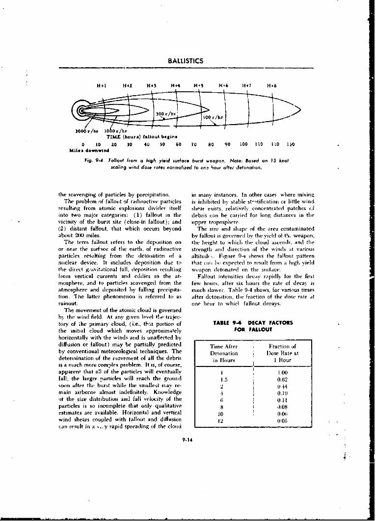
BALLISTICS
H+1 H+Z H+3 H +4 H+5 H46 H117 H÷8
3000,/hr 10 Or/hrTIME (hours) fallout begins
0 10 ,0 30 40 50 60 70 80 90 100 110 1.40 1:10Mtles downwind
Fig. 9-4 Fallout from a high yieid surface burst weapon. Note: Based on 15 knotscaling wind dose rates normalized to on.a hour alfer detonation.
the scavenging of particles by precipitation. in many, instances. In other cases: where mixingThe problem of fallout of radioactive particles is inhibited by stable st-'tification or little wind
resulting from atomic explosions divides itself shear exists, relatively concentrated patches (.finto two major categories: (1) fallout in the debris can be carried for long distances in thevicinity of the burst site (close-in fallout); and upper troposphere-(2) distant fallout, that which occurs beyond The size and shape of the area contaminatedabout 200 miles. by fallout is governed by the yield of th. weapon.
The term fallout refers to the deposition on the height to which the cloud ascends, and theor near the surface of the earth, of radioactive strength and direction of the winds at variousparticles resulting from the detonation of a altitudt -. Figure 9-4 shows the fallout patternnuclear device. It includes deposition due to that cati be expected to result from a high yieldthe direct g~avitational fall, deposition resulting weapon detonated on the stnuace.from vertical currents and eddies in the at- Fallout intensities decay rapidly for the firstmosphere, and to particles scavenged from the few hours; after six hours the rate of deca\ isatmosphere and deposited by falling precipita- much slower. Table 9-4 shows, for various timestion. The latter phenomenon is referred to as after detonation, the fraction of the dose rate atrainout. one hour to whicl fallout decays.
The movement of the atomic cloud is governedhv the wind field. At any given level the trajec-
tory of ;he primary cloud, (i.e., that portion of TABLE 9-4 DECAY FACTORSthe initial cloud which moves approximately FOR FALLOUT
horizontally with the winds and is unaffected bydiffusion or fallout) may br partially predicted Time After Fraction ofby conventional meteorological techniques. The Detonation Dose Rate atdetermination of the movement of all the debris in Hours 1 Houris a much more complex problem. It is, of course,apparent that all of the particles will eventually 1 1.00fall; the larger particles will reach the ground 1.5 0.62soon after the burst while the smallest fr.av re- 2 0 44main airborne almost indefinitely. Knowledge 4 0.19
of the size distribution and fall velocity of the 6 0.11particles is so incomplete that only qualitative 8 J.08estimates are available. Horizontal and vertical 10 0.06wind shears coupled with fallout and diffusion 12 0.05can result in a -. y rapid spreading of the cloud
9.14
THERMAL AND NUCLEAR EFFECTS
9-18 LONG-TERM RESIDUAL RADIATION HAZARD
Of the fission products which present a poten- less sensitive location in the body, indicatestial long-term hazard from either the testing of that for the same amount of stratospheric fall-nuclar weapons in peacetime or their use in out, the residual cesium-137 will be less of awarfare, the inoýt important are probably the general pathological hazard than the iesidiialradioactive isotopes cesium-137 ind strontium- strontium-90-90. Since both of these isotopes are fairly Attention will now be given to what is proha-abundant among the fission products and have bly the more serious long-term radiation hazard.relatively long half lives, they will constitute at Because of its relatively long radioactive ha!flarge percentage of any world-wide fallout. Of life of 8 years, and its appreciable yield in thecourse, the activity level due to these isotopes at fission process, strontium-90 accounts for a con-late times in the local fallout pattern from a siderable fraction of the total activity of fissionsurface or subsurface burst will be considerably :rdti,ets which are several years old. Thus, evenlarger than in the world-wide fallout from a sý; -h material is has been stored in the strato-given nuclear burst, sphere for several years will be found to contain
Cesium has a radioactive half aife of 30 years a large percentage of this radioactive species.and is of particular interest in fallout that is more Strontium ir chemically similar to calcium, anthan a year old because it is the principal con- eh,: nent essential to both plant and animal !ife;stituent whose radioactive decay is accompanied a Wown human being, for example, contains overby the emission of gamma rays. The gamnia rays twoPounds of calcium, mainly in bone. As aare actually emitted, within a very short time. conseq-icnce of the chemical similarity, strontiumb% a high-energy state of the decay product, entering the body follows a path simila- tobarium-137. The chemical properties of cesium calcium and therefore is found almost entirely inresemble those of potassium. The compounds -:f the skeleton, from which it is eliminated verythese elements are generally more soluble than Nlow]v Thus, the half life of strontium in humanthe corresponding compounds of strontium andt b ne is estimated to be about ten years. Thecalcium; and the details of the transfet of these prGbability of serious pathological change in thetwo pairs of elements from the soil to the human body of a particular individual, due to the effectsbody are quite different. Cesium is a relatively of internal radioactive material, depends uponrare element in nature and the body normally the inter,sitv and energy of the radioactivity andcontains only small traces. Consequently. the upon the length of time the source remains in thebiochemistry of cesium has not been studied as body. Although strontium-90 emits only betaextensively as that of some oi the more common pi:rticles (no gamma rays), a sufficient amountelements. It has been determined, however, that of this ýsotope can produce damage because oncecesium-137 .istributes itself within living cells it gets into the skeleton it will stay there for ain the same w". as potassin•, so that it is found long time. A- a result of animal experimenta-mostly in muscle. Base.l on one experiment tion, it is be!ieved that the pathological effectsiiith several human subjects, the current esti- which may result from dam, sing quantities ofnate of the time required for normral biological strontium-90 are anemia, bone necrosis, and cer-
processes to reiuce the amount of cesium in the tain t)pes of cancer, possibly leukemia. It is thebody by one-half, i.e., the biological half life, combination of physical and chemical propertiesis 140 days. Because of the penetrating properties of stcontium-90. namely, its long radioactive half-•f the gamma rays from the decay of cesium-137, lifc and its similarity to calcium together withthe radiat.on is distributeci more or less uniformly the nature of the pathological changes which canto all parts of the body. Although the radioactive result from concentrations of radioactive materialdecay of cesium-13 is accompanied by gamma in th, skeleton, that make strontium-90 the mostray emission, the rcla'ivclv short time of stay. important isotope (so far -as is known) as atogcther with muosi of the cesium being in a possible cause of harmful long-term effects of
9-151-
r r a - i- - - - - ,.!. -rt- -. ,r.C -. Z U tt a'lr

BALLISTICS
fallout, the intensity of the secondary radiation (bremss-Genetic effects due to strontium-90 are rela- trahlung) produced by the beta particles is low.
tively insignificant. IJr the first place, owing to Finally, the amount of strontium-90 in soft tissue,thcit very short range in the body, the beta from which the beta particles might reach theparticles from this isotope in the skeleton do not reproductive organs, is small and may be neg.penetrate to the reproductive organs. Further, lected in this regard.
REFERENCES
I Otto Oldenberg, Introduction to Atomic Phys- 2 Effects of Atomic Weapons, Department of theics, McGraw-Hill Book Co., N. Y., Chap. 19. Army Pamphlet 39-3., May 1957.
91
9.16 '''
-.rr3 nsa tC c ~~ ra~~-S~ |.

CHAPTER 10
BALLISTIC ATTACK OF ARMOR USING KINETICAND CHEMICAL ENERGY EFFECTS
10-1 GENERAL
A specialized field of terminal ballistics and and one which threatens personnel with fire andone in which new developments are or" critical suffocation. These weapons however are not ofimportance conceins consideration of the mears the highly specialized variety as are kinetic oravailable to accomplish defeat of prot.acted chemical energy type rounds.targets, primarily armor and concrete. TI~ese Successful attack of any target is dependeittwo defensive devices, along with the bunker- upon the characteristics of the ta, rget itself, hencetype field fortifications that were so effective in this phase of terminal ballistics is divided intobattles throughout the Pacific regions in World two parts: Chapter 10 for the study of the defeatWar I1 and the Korean War, frequently require of armor; and Annex P to Part 2, the defeat ofspecial techniques !or attack. Include3 in the cnncrete. Both the offensive and defensive aspects
types of weapons suitable for attacki'ig such of both types of material will b, consideredtargets are napalm or fire bombs which are a b-cause both may be in the handh of the attackertremendously effective psychological weapon an.J the defender in future combat.
10-2 TYPES OF ARMOR MATERIALS
Armor is generally thought of as being steel, offset the increased cost of these materials overand almost all armor in use is steel. However, steel. In addition, certain nonmetals sho\k prom-research indicates the possibility of alue'r,,im. ise as armor materials, particularly in the role of
titanium, and other light metals being used for body armor. The three major applications ofarmor, particularly whec w -,ght savings would steel as armor include:
10-2.1 ROLLED HOMOGENEOUS homogeneous steel amd can be welded into a
STEEL ARMOR vehicle structure with little difficulty. It has highFotaostcmmnghness and dciiyadafrstebs
For a number of years the most common type tou ductility and affcrds the bestof annor used in the construction of combat protection against the shock of impact of rela-vehicles has been rolled alloy steel produced and tively large caliber projectiles as well as the
heat-treated so as to give it, asnearly as possible, blasts of high explosive missiles. The bow armor
the same chemical and physical characteristics of the armored infantrv vehicle (Figure 10.1) isthroughout its structure. Chemically it consts an of rolled
of steel with the following alloying elementsadded: 0.50-t.251 chromium; 0.5-1.5% nickel;
STEEL ARMOR0.3-U.6% niolybdenum; 0.8-1.6% manganese; and0.30% carbon. It is usually used as plate, furnish- Chemically, east homogeneous armor is virtu-ing conveniently flit walls on which to base the ally the same as rolled homogeneous armor. It is
design of the inside of the vehicle, although it given its shape by casting in a mold and receivescan be bent to a limited extent to form curved its optimum ballistic properties by subsequent
surfaces. It is more easily produced in large heat treatment. The advantage of cast armor is
qoantities than either face-hardened or cast that it can be, molded into almost any shape,
10.'
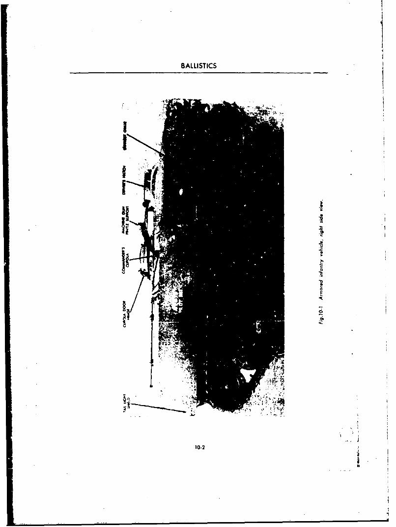
BALLISTICS-
10-2
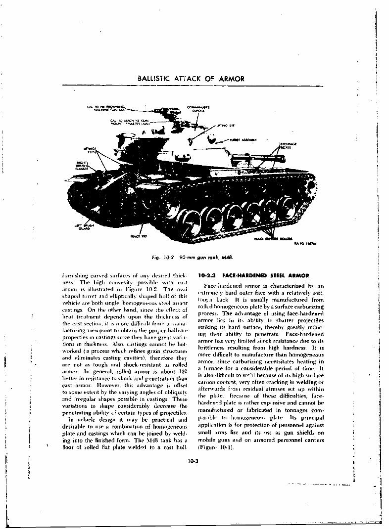
BALLISTIC ATTACK OF ARMOR
CAL 50MC, fiP
.Fig. tO.2 90-mm I , 1
lexis
furnishing curved surfaces of any. desired thick- 10-2.3 FACE-HARDENED STEEL ARMOR1hess. The high convex.ity possible with cast Face-hardened armor is characterized by an!armor is illustrated in Figure 10-2. The oval exrmlIadotrfc iharltvl otshaped turret and elliptically shaped hull of this extrmel hard. utr fssacelit anrelactireld frotvehicle are both single, homogeneous steel arriur ""it ak ti saly auatrdfocastings. On the other hand, since the cffec~t of rolk-d homogeneous plate by a surface carburizing
,heat treatment del)ends upon the thickncss of process. The advantage of using face-hardenedthe astscctoa.it s moe dffiuir romarmor lies iin its abhlitv to shatter projectiles
Sfacturning viewvpoint to obtain the proper ballistic striking its hard snrface, thereby greatly rcdiuc-prprisin castings sirce they)aegetvr• ing their ability to penetrate. Face-hardened
prprishv groreastrylmie vacnessanedu o-ttions in thickness. Also, castings cannot he hot- armorlenas resulimtedg frockhrehistancesdueto itsworked (a process which refines grain structures hmorlees reff ulting mnfromthighthardness.entois
and eliminates casting cavities), therefore they oedfiutt aufcueta ooeeuare not as tough and shock-resistant as rolled armor, since carburizing necessitates heating inarmor. In general, rolled armor is about 15./ a furnace for a corsiderable period of time. IL
I better in resistance to shock and penetration than isao(ifcutow-'beueoftshgsraecastarmr. oweer.thisadvntae i ofset carboon corte-it, very often cracking in welding or
cato somer exten veby thevring advntgles of ofisut afterwards f-ouu residual stresses set up within" toan irregua shapes possibleaing castnges. Tfeseuit he plate. hecatttse of these difficulties, face-
i anrdeiirdgularcsisprsthersibleniiveaandncannotehe;, ~variations in shape considerably decrease the hardneftid orat fabriathed instonnages corn-oS~~~penetrating abilits., J certain types of projectiles, auatrdo arcae ntnae onSIn v-ehicle design it may be practical arnd par.,bhe to homogeneo'us plate. Its principali ~desirable to use a combination of homogeneous applica•tion is for protection of personnel againsti ~plate and castings which can be joined by weld- small items fire and its ,iw as gun shields on
ing into the finished form. The .148 tank has a mobile guns and on armored personnel carriers
" floor of tolled flat plate welded to a cast hull. iFigure 10-1).r1 .-HT
-----------WARD
LE Gk&*ATV* ILA00M

.U MBALLISTICS
10-2.4 NONFERROUS ARMOR IATERIALS importance of weight saved woulid offset theDuring and since World War !1, considerable disadvantages cf substituting a more expensive,
research has been devoted to investigating the strategically crit.al material i, place of steel.a-mor application of light metals, principally For protection against shaped charges andtitanium, alum~num, and magnesium alloys, and against shock from high explosive projectiles andalso uf certain nonmetals such as nylon, fiber- mines, where bulk and thickness are more .-n-glass, and silicate aggregates in mastic binders. pertant than the strength of the material, plastics.The interest centered upon the relative protec- gl:iss, and ordinary silicate rock in a mastic
tion that would be given against various types binder offers greater protectio i than an equalof ballistic attack zompared with that provided weight of steel.by an equal weight of steel. These investigations None of these noiiferrous armor inateriais has
h proved definitely, that for weights of material vet come into general usage; however, theirpermissible in body armor, steel is inferior to future is assured by the improved protectioncombinations of aluminum and nylon for protec- which is provided, on an equal weight basis,tion against small caliber bullets and high against certain types of attack. The search forexplosive shell fragments. lighter armor materials is continuous, because
The alloys of certain light metals show future weight is one of the most important factors inpromise for use as aircraft armor where the the use of armor.
10-3 SURFACE DESIGN
In addition to providing the maxi:num advan- against a surface which provides less protectiontage of ohliquity, the apportionment of protection and which in most cases would not be exposedin accordance with the expected severity and to attack. Moreover. re-entrant angles often causedirections of attack, and the uniformity of pro- a thinner wall section not exposed to direct attacktection from any one direction of attack, the to stiffer peimetration when attacked by the blastoptimum design in an armor structure will also of a high explosive projecile.provide for an overall convex surface This re- Surface irregularities, either inside or outsidequires avoiding re-entrant angles and irregu- the vehicle, tend to create weaknesses in the'aritie, such as joints between sections, sudden armor and iherefore should be avoided. A flat.da;inges in thickness, sudden changes in obliq- smooth wall of constant thickness offers the he-tuity. installed components, and attachments resistance to severe attack, principally becausewelded to either the inside or outside surface the shock of impact can he uniformly absorbedof the a .mor.
A fiat or a convex surface tends ta rejct im- over the entire area. Any irregularity. whetherAI fla or reno convex sufc protntis bead reetampacts at 3bliquities and is by far preferable to it be a reinforcing brace, a protective bead, a
a concave surface contaiving a re-entrant angle sudden change in thickness, a sudden change in
(Figure 10-3) which tends to catch attacking obhquit., or a welded joint, tends to restrict
projectiles. thereby increasing the dangers of ,iniform defo~mation and may set uip. near thericochet and bullet splash. The latter condition irregularity, stress concentratiorn of sufficientofteni causes an attacking projecile to be tunted magnitude to cause failure.
10-4 FABRICATION OF MOBILE ARMOR STRUCTURES
.lmost all fabrication of structures of homo- tank when the armor is struck on the outside)geneous armor ! and therefore, the greatest per- constitute a hazard to the crew and to equipmentz'entage of .,J1 grmnr fabrication) is c•,mplished within the tank, and since welded joints in homo-bv arc weldi,,. Since flying boltheads, nuts. ind geneous armor cez be made hallisv "- strongerrivetheads (detached from the inside wall of the than either bolted or riveted joints, whenever
10-4
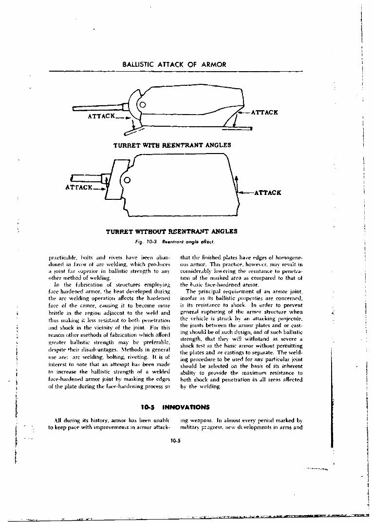
BALLISTIC ATTACK OF ARMOR
ATTAC• •--• •• -- ATTACK
TURRET WITH REENTRANT ANGLES
0A -ATTACK
TURRET WITHOUT REENTRANT ANGLESFig. 10.3 Reentront angle effect.
practicable, bolts and rivets have been aban- that the finished plates have edges of homogene-doned in favor of are welding, which produces ous armor. This practice, howevur, may result ina joint far superior in ballistic strength to any considerably lovering the resistance to penetia-other method of welding. tion of the masked area as compared to that of
In the fabrication of structures employing the basic face-hardened armor.face-hardened armor, the heat developed duri.ng The principal requi-ement of an armor joint.the arc welding operation affects the hardened insofar as its ballistic properties are concerned,face of the airmor, causing it to become more is its resistance to shock. In order to preventbrittle in the region adjacent to the weld and general rupturing of the armor structure when
thus making it less resistant to both penetration the vehicle is stru. b% an attacking projectile.; the joints between the armor plates and or cast-
* and shock in the vicinit' of the joint. For thisSreason other methods of fabrication which afford ing should be of such dcsign, and of such ballistic
greater ballistic strength may be preferable, strength, that they will withstand as severe ashock test as the basic armor without permitting
despite their disadvantages. Methods in general the plates and or castings to separate. The weld-use are: arc welding, bolting, riveting. It is of p he used for asy parte. jointSi2ng procedure to be used for any particular joint
* interest to note that an attempt has been made should be selected on the basis of its inherent" to increase the ballistic strength of a welded ability to provide the maximum resistance to
face.hardened armor joint by masking the edges both shock and penetration in all areas affectedof the plate during the face-hardening process so by the welding.
10-5 INNOVATIONS
All during its history, armor has been unable ing weapons. In almost every period marked byto keep pace with improvemenLs in armor attack- military progress. new dcvelopments in arms and
10-5
BALLISTICS
amnmunintion have created additional dlifficuilties question arises its to vvhat c)I -iigve, inl armoreven bcfore satisfactorx' solutionis to 0o(1 and exist- might be miade iii aii effort to defeat, or ating armor problems had been found. Because leasst reduce. the destructive effect of iniodern(his situdtion is particularly true today, thu projectiles.
10-5.1 SPACED ARMOR is basically inferior to a single piece of armor of
Apart from the develoipmenet of new miaterials, the samne overall thickness. This plienoumeioi.
further consideration of the questiion suggess has been ver~fied by repeatud test firitigs wit'i
that a solution to the problem may result either Aitt ilupe csjs!Aiug lot increasted 1141 stiv per-
through the use of spaced armor or throuigh some forniance of armor thrJoukgh the use of lamnin.~t d
new development in composite armor. While plate.
experiervce indlicates that the latter approachoffers little or no chance of success, there is 10-5.3 COMPOSITE ARMORalwavs at possihility that the dis_-overv of new
nmaterials ifld methods may change the picture Since W~orld War If considerahle expert-suficent% o l~eini a solution. During World inentation hats been condacted to establish data
%'Va 11theGeransuse spcedarmr toa prtientto he ermnaleffctsof various kineticlimtited oxtent. Whether or not Jt can Le advan- energy. HIE.. A.T., and H.E.. rounds on armortageotislv used in the future depends upon furthez in use or in the development stage. One shouldinvestigation andi development. Spact d armor considecr the possible future utilization' cf non-vmnsists of two or more plates located at relativelv fterrouis mnetals arid steel p~late by the intimatevgreat distances frnim each other. In order to bonding of two or more of them into a compositedefeat armnor piercing project.'es. the inuitial plate form providing the mavimrumi possible protectionmost either break uip the at-tacking. project;'e or atgainst all t~pes of rounds, with the compositeturn it miuaiciently freitn its trajectory to pr-"'ent ainmor affording better protection p:ýr unit ofpenetration. In or-der to ]lefeat hollow charge %%eight than steel. This opens the door forprolv, tiles, tht- initial plate must he able to with- comiposite armaor of aluminum or mnagncsitt iýStiil the attendant ferces so that the ene~gy allnvs affording ias Muich Vrotection as steel forreleased ý&ill he adequately dissipated before a shock andl penetration of kinetic energy rounds;suconular-x plate can be attacked. Alteruate silicate aggregates in mastic hinders affordingprotective concepts inclu!de the i~se of externally prostection from H.E. and A.T. rounds; and resili-mounted spikes to spoil stand off distance of cot materials for shock action. Comnbinat ions ofincoming rounds, detonation of small shaped mnaterials in a composite form obvious!% willchanges against the jet of the attacking rounds; require great strides in fabrication techniqutes itsresilient screens. and coatings of violently oxidhiz- well as increased performance Gver that presentlyinA material to ci~usc disposal of the let. An" e.wt otme ehooiinvestigat ions which may be conducted mus't possible. However wit cotne ehoo al
include such factors as silhouette nritthod ot advsancemuents, the future may well see the fabri-
support, weight, jettisoninig, and mobilitY. c,'uof composite armor ats at partia' answerat least in the search for maximnum protection
10-5.2 LAMINATED ARMOR against the imiltiplicity of rounds ctumrentlyLaminated armor of lae-io-a rof steel available.
10.6 NECESSARY BALLISTIC PROPERTIES OF ARMOR
The necessar v ballistic proneirties which are tration. resistanvv to sl.ock-, and resistance torequired of arnmor consist of resistance to pene- spalling.
10-6

IIBALLISTIC ATTACK OF ARMOR
10-6.1 RESISTANCE TO PKINEIRATION 1"-d.3 kESISTANCi TO SPALWNO
Resist.nce to penetration is that property l,,..'tanecv io -.plling is that property whichwhiich prev-o!nts a projectile trom passing partially tnds Io resist ( rac(king, flaking, or brcaking away
or entirely thiough armor plate. When penctra - of the artnoi phte. particularly on the innertion occurs, either a cvh idrical plug is driven surface oljpusite the jxiint of impatt. In general, "from the hack of the ple'te or the metal is pushed win,:, %palling 'cerars, the diameter of the open-aside, some of it flowing toward, thw e.xpos,'( ing on the rveir Silface of. the plAte is coitsiderablvface where it forms a lip. and the reinmalmdh greater than the caliber of the projectile whichbeing pushed to,, ards the imexposed ..urfave caused penetration. In substance, resistance to(back) forming a convex protruision which may spalling is a measure of the soundness of thebe expelled in one piece or as scattered trag- steel and the qu.lity of itO heat treatmentments (Figure 104). (Figure 10-6).10,-6.2 RESISTANCE TO SPOCK have the greatest influence on its bal!istic
Resistance to shock is that property which properties are:permits armor to absorb, without cracking or (a) Hardness: the ahilitv of zhe armor to resistrupturing, the encgy expended against it b. indentation.either an attacking projectiie of relatively large (b) Toughness: the ability of the armor tocahiher, cr the explosion of a high explosive pro- ahsorh energy before fracturing.sectile. Because of the very high velocities at
whi'h projectiles strike and at which high order (c) Soundness: the absence of local flaws,explosions take place, this energy must be ab- cavities, or weaknesses in the armor. Unsound-
sorbed in an extremely short period of time. Low ness is not so often found in rolled arm, as in
temperature decreases the shock resistance of cast armor, because of the mechanical working
armor by making it more brittle and thus less which has been done during the hot-rolling
able to absorb the shock (Figure 10-5) process.
10-7 EFFECTS OF OBLIQUITY AND HARDNESS ON PERFORMANCE OF ARMOR
The ballistic properties of armor depend upon projectile is said to be undermatching in iclation-several factors: the type and thickness of the ship to armor tl.ickness; if T D is equal to 1, 'hearmor; the ratio of the thickness of the armor to projectile is said to be matching; an4, if T D isthe caliber of the projectile (TD ratio); the type less than 1, the projectile is overmatching. Whenof projectile; the striking velocity; the obliquity TD ratio is varied, there is considerable differ-of impact; and the hardness of the armor. ence ilii the displacement of metal as the projectile
The ratio between the armor thickness (T) and pushes through the plate. The performance ofthe diameter of the projectile (D) is expressed as different caliber projectiles is roughly compa-the TiD ratio. If TID is greater than 1, the rable when the T D ratio remains constant.
10-7.1 EFF1.T Of OBUQUITY UPON curves begin to rise more and more rapidly. TheRSSISTANCE TO PENETRATION sharp rise is attribitable to the failure (fracture
or shatter) of the projectile thereby increasingWt:en tlhe obliquity of impact against a given resistance to pent-tratioti. The location of the
thicknes,- of armor is increased resistance to b ginning of the rapid rise and die steepness ofpenetration is also increased. Basically, little or the curve at any particular cbliquitv depcnd uponno change in resistance to penetration occurs as several factors already mentioned: the T D ratio,
the obliquity begins increasing from 0- until the hardness of the armor, and the type of prosomewhere in a range of from 100 to 20' the jectile. In general, high obliquitv impact causes
10-7
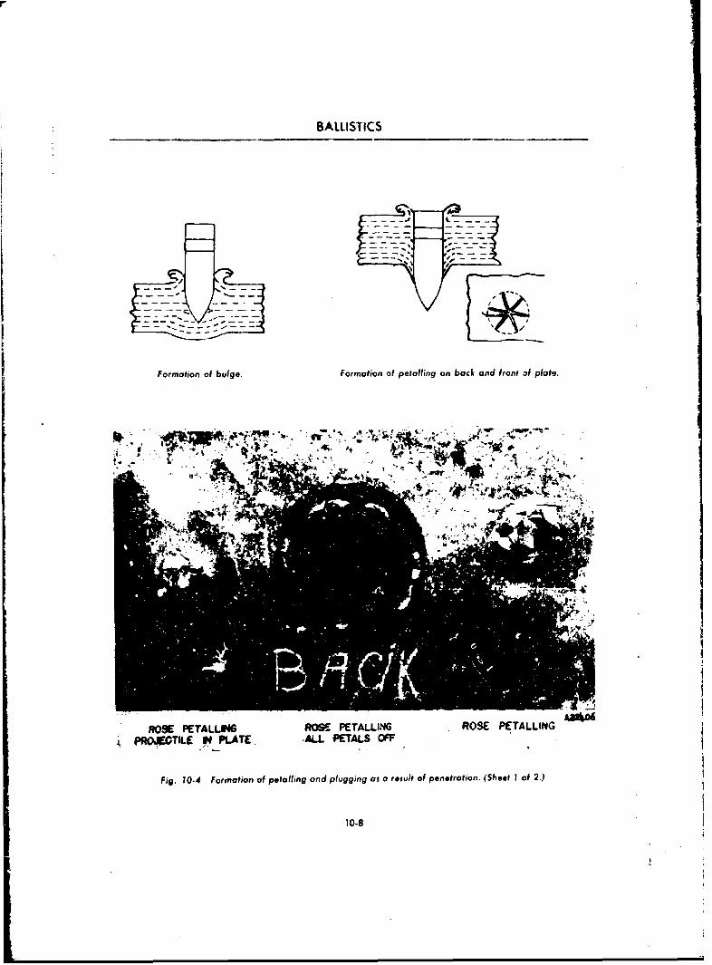
BALLISTICS
Formation of bulge. Formation of peto fling on back and front of plate.
ROSE PETALLM4 ROSE PETALLINIG ROSE PETALLIIVG
SPROJ90TILE IN PLATEý ALL PETALS OFF
fig. 10-4 Formation of potalling and plugging as a result of penetration. (Sheet I of 2.)
10.8
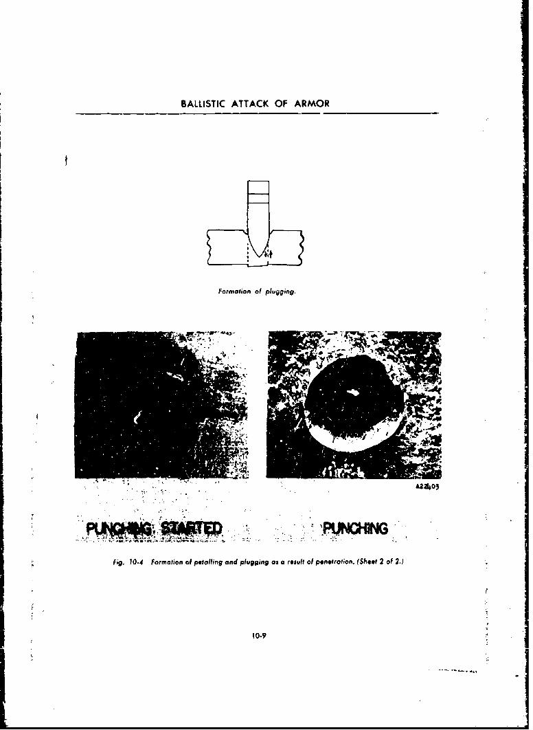
BALLISTIC ATTACK OF ARMOR
Formation of plugging.
.V
. QFig. 10-4 Formation of poto fling and pl ugging as a result of penetfotion. (Sheet 2 of 2.)
10-9
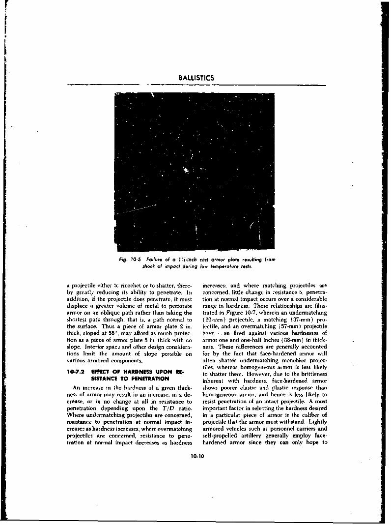
BALLISTICS
Fig. 10-5 Failure of a 11"s-inch cost armor plate resulting fromshock of impact during low temperature tests.
a Projectile either tc ricochet or to shatter, there- increases; and where matching projectiles areby great! ' reducing its ability to penetrate. lit concerned, little change in -esistance tk. penetra-addition, if the projectile does penetrate, it must tion at normal impact occurs over a considerabledisplace a greater volu~me of metal to perforate range in hardness. These relationships are illus-armor on an oblique path rather than taking the trat,2d in Figure 10-7, wherein an undermatchingshortest pata through; that is. a path normnal to (20-:rxm) projectile, a matching (37-mm) pro-the surface. Thus a piece of armor plate 2 in. ifjctile, and an overmnatching (57-mm) projectilethick, sloped at 55', may afford as much protec- b?ve - en fired against various hardnesses oftion as a piece of armoi plate 5 in. thick with no armor one and one-half inches (38-mm) in thick-slope. Interior spac.i and other design considera- ness. These differences are generally accountedtions limit the amount of slope po!:sible on for by the fact that face-hardened armor willvarious armored components. often shatter undermatching monubloc projec-
tiles, whercas homogeneous armor is less likely10-7.2 EFFECT Of HARDNESS UPON 111- to shatter them. However, due to the brittlenes's
SISTANCE TO PENETRATION inherent with hardness, face-hardened armor
An increase in the hardness of a given thick- shows poorer elastic and plastic response thannesh of armor may resuilt in an increase, in a de- homogeneous armor, and hence is less likely tocrease, or in no change at all in resistance to resist penetration of an intact projectile. A mostpenetration depending upon the T/D ratio. importar~t factor in selecting the hardness desiredWhere urndermatching projectiles are concerned, in a particular piece of armor is the caliber ofresistance to penetration at normal impact in- projectile that the armor must withstand. Lightlycrease:; as hardness increases; where overmatching armored vehicles such as personnel carriers andpr-ijectiles are concerned, resistance to pene- self-propelled artillery generally employ face-tration at normal impact decreases as hardness hardened armnor since they can only hope to
10-10
BALLISTIC ATTACK OF ARMOR
v ithstand small hms fire and shell fragments 10-7.3 DISCUSSIONwhich would be undermatching. Since the resistance to shock is a measure of
No mnathematical relatiouship has yet been the ability of armer to absori, energy, the obliq-established to link the effects of ob!iquity and uity of attack has little effect other than that athardness upon resistance to penetration, for no high obliquity impact, the armor will absorb
two sets of conditions among type and thickness less energy in deflecting the projectile into rico.of armor and type and model of projectile neces- chet than if the projectile imbedded itself. How.sarily produce exactly the same result: therefore, ever, the hardness of armor has great effect uponFigure 10-7 cannot be gi-.'en general application, its shock resisting properties. Armor of the higherThe designer of a combat vehicle should establish hardnesses tends to be more brittle and to crackarmor requirements only after a study of a com- under severe shock of impact or blast, whileplete tabulation of data for each type and thick- armor of the lower hardnesses tends to be moreness of armor and each caliber and model of tough and ductile and to withstand greater shock.projectile to be N)nsidered. Due to the magni- But armor of too low hardness cannft providetud2 of the effect of increased obliquity upon sufficiently high resistance to penetration or mas-resistance to penetration, every advantage should sive deformation, so a compromise is necessary.be taken of the effect of obliquity in the design The hardness of armor and obliquity of attackof all combat vehicles, gurn shields, and other have litthe effect upon resistance to spalling, asarmor structures. Wherever possible, armor stir- spalling is essentially depe,,dent upon the sound-faces presented to attack by enemy fire should be iess of the steel and the quality of its heatinclined at the highest obliqu ties permissible treatment. However, once perforation has been
vithin the limitations of the other design con- obtained, armor plate of the higher hardnessessiderations. will generally spa!1 more (Figare 10-8).
10-8 KINETIC ENERGY PROJECTILES
10-8.1 DEFINITION OF TERMS (e) Shatter. The breaking of the projectile
(a) Penetration-perforation. In considering into a numbe, of pieces by complex shearing
the effects of missiles o0 targets it has been found actions rather than by brittle failure.useful to distinguish between penetration and (f) Shatter velocity. That striking velocity at
perforation. The term penetration is reserved for which the projectile, for a given angle of in-the entry of a missile into the armor without cidence, will shatter into two or more parts whenpassing through it. The term perforation implies striking a given type of armor.the passage of the missile completely through (g) Angle of incidence or striking angle. The
the armor.
(b) Target. That materiel or personnel whose angle measured between the normal to the armor
injury or destruction will nullify or lessen the at the point of impact, and the tangent to the
effectiveness of the enemy. In the specific case trajectory at the same point (see Figure 10-9).
of a tank the target may be the crew, ammuni- i h) Striking energy. The kinetic energy pos-tion, fuel system, radios, fire control equipment, sessed by the projectile at the instant of impactarmament, or structural or moving parts such as due to its mass and striking velocity. The kineticthe engine, power train, track, etc. The target energy of rotation of the proiectile is usuallyitself is usually highly vulnerable if its protective ignored.armor can be perforated.
(c) Striking velocity. Velocity of the projec- (i) Armor piercing cap. A metal cap affixed
tile at the instant of impact. to the nose of a projectile in order to ircrease the
(d) Residual velocity. Neelocity of the pro- velocity at which shatter will occur by decreasing
jectile after perforation, initial impact stress due to inertia.10-11i
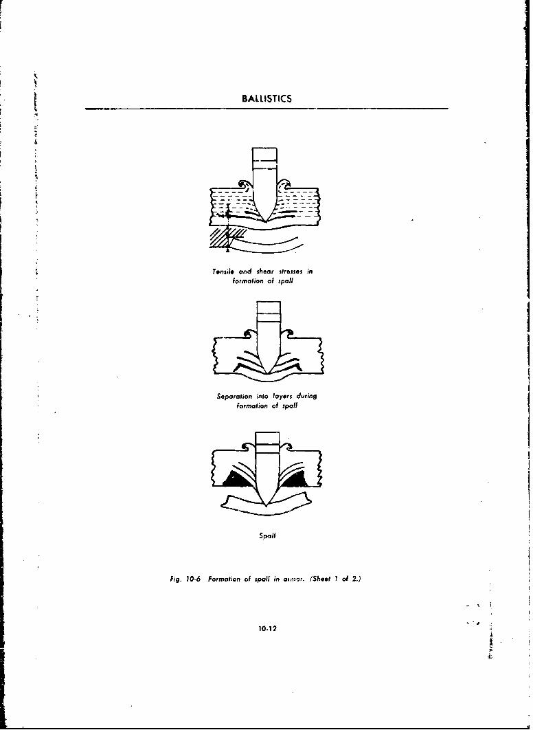
BALLISTICS
-- 7
* Tensile and shear stresses information of spoil
Separation into layers duringformation of spaol
Spill
Fig. 10-6 Formation of spaol in arm or. (Sheet I of 2.)
10-12
-L
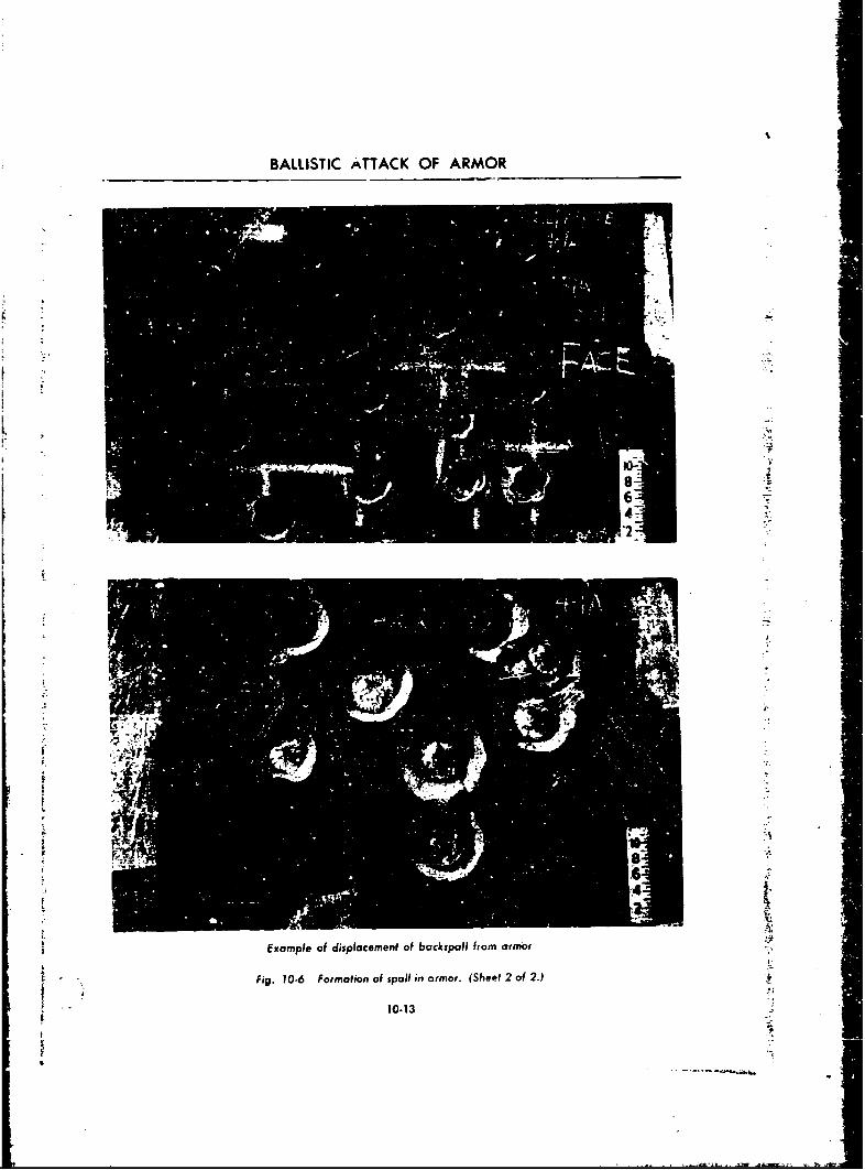
BALLISTIC ATTACK OF ARMOR
I--
Example of displacemrent of backsplil from armor
Fig. 10-6 Formation of spoil in ormor. (Sheet 2 of 2.)
I 10-13
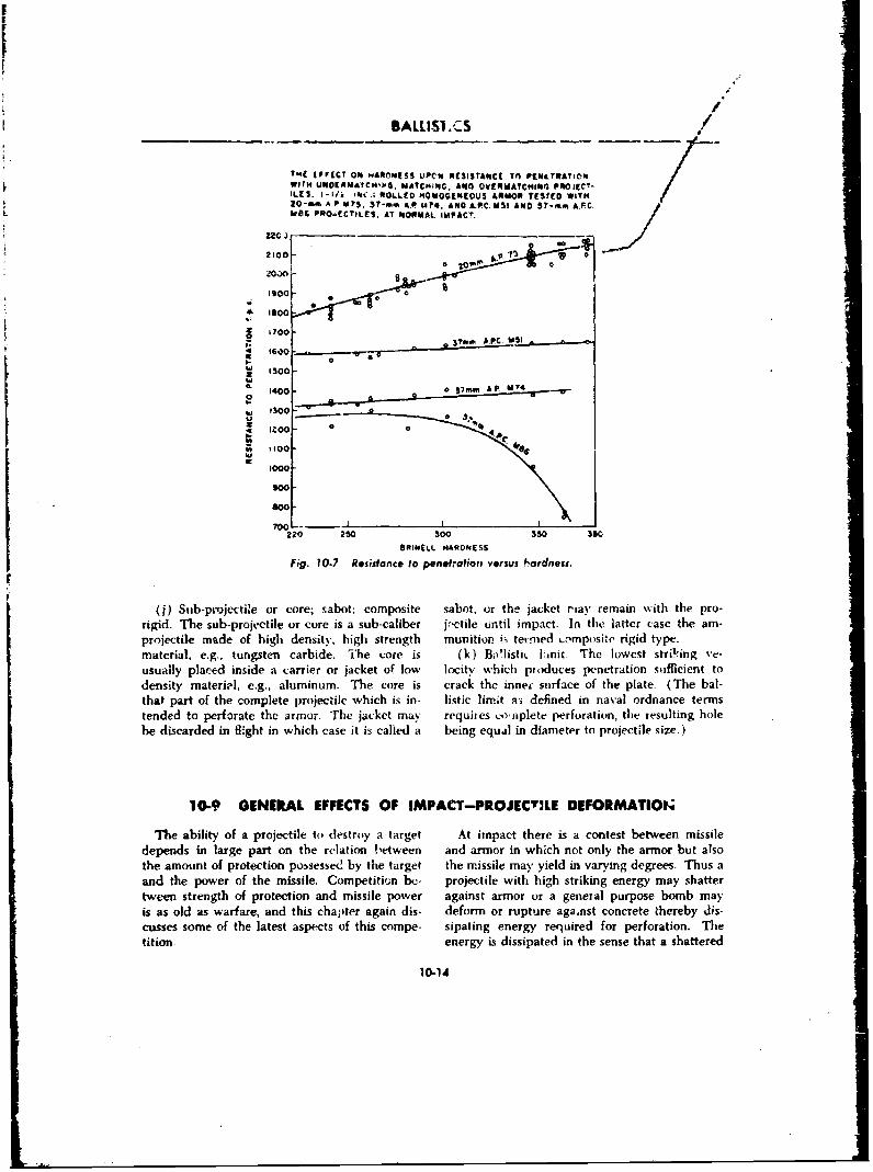
BALISI .CS
1-41 IFFECT ON1 PiAON5S3 uPCI'N RESISTANCE Tn PEN&I111ATIC'I
WFITH UNOEEMNATCHN4v, MATCNING. ANO0 OVE*MAYCNII401 PROJECT-ILES. 1-1/i INC. ROLLED I4MOVGENIOUS &*NOR TESTED WITH20-m~m A.P M?5, 37-mmA ALP UY4. AND A.P.C. U51 AND 57-mmR A.FC.
L WEIS PRO.IECTILES. AT NORMAL IMPACI.
000
* 600
* 700-
41600-
"15001400 AV 7
11000 *
1000
8000
220 250 So0 350 360
ORINELL HARDNESS
fig. 10.7 R~sisianCe to penetrationl versus hardness.
(j) Sub-projcctile or core; sabot; composite sabot, or the jacket riaav remain with tihe pro-rigid. The sub-projectile or core is a sub-caliber j,-ctile un~til impact. In the latter case the am-projectile made of high density, high strength munTIor01 i; telnmed LDMP{Isitc rigid type.material, e.g., tungsten carbide. The core is (k) Boflistk Fink,. The lowest stril-ing ve-usually placed inside a carr ier or jacket of low locity which pitiduces penetration sufficient todensity materi.l, e.g., aluminum. The core is crack the inner surface of the plate. (The bal-that part of the complete p~rojectile which is in- listic lirn-t Fri defined in naval ordnance termstended to perforate the armor. The jacket may requires co'aiplete peirforation, the resulting holebe discarded in flight in which case it is called a being equal in diameter to projectile size.)
10-9 GENERLAL EFFECTS OF IMPACT-PROJECTILE DEFORMATION~
The ability of a projectile to dlestroy a target At impact there is a contest between missiledepends in large par-t on the relation !,etween and armor in which not only the armor but alsothe amount of protection po~ssessed by the target the missile may yield in varying degrees. Thus aand the power of the missile. Competition bc- projectile with high striking energy may shattertween strength of protection and missile power against armor or a general purpose bomb mayis as old as warfare, and this chapiter again dis- deform Or rupture against concrete thereby dis-cusses some of the latest aspects of this compe- sipating energy required for perforation. Thetition. energy is dissipated in the sense that a shattered
10-14
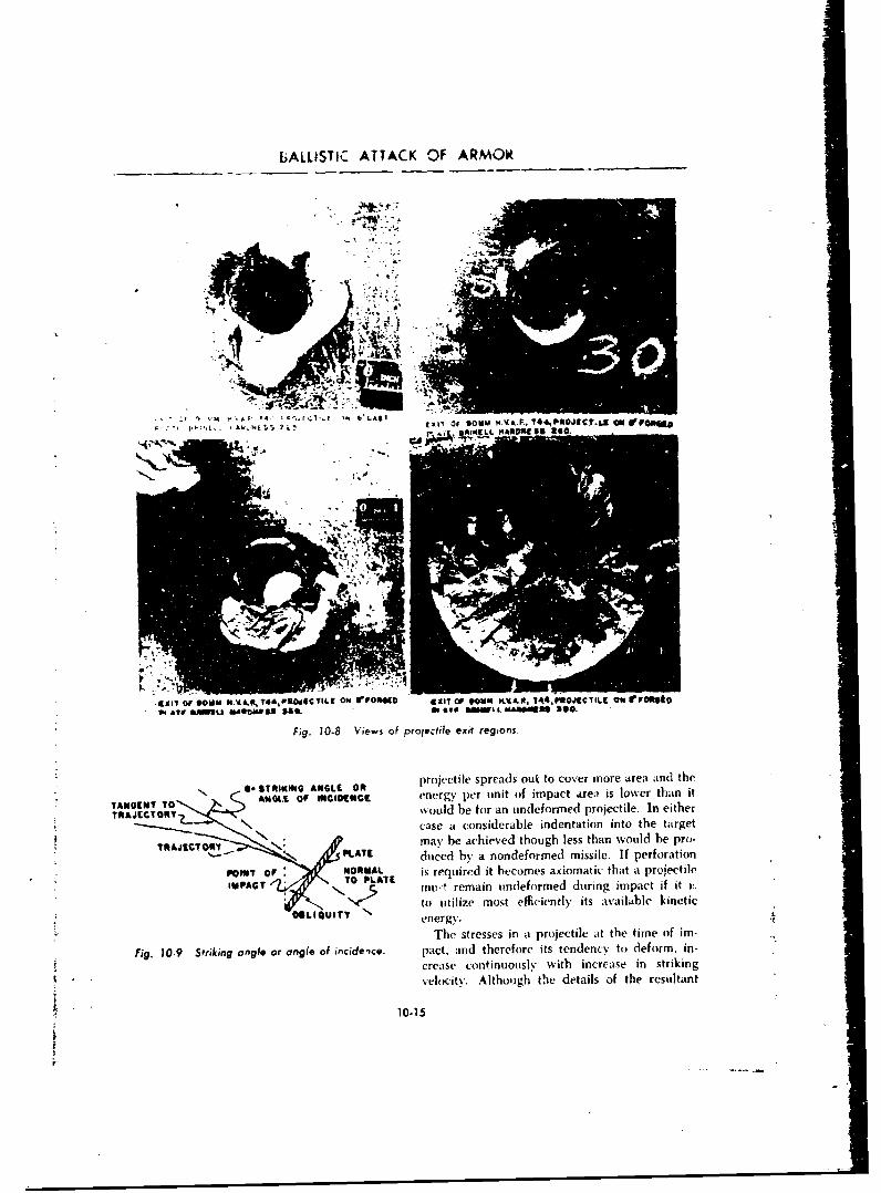
bALLISTIC ATTACK OF ARMOR
A..
flI4. _ ~IS mo
-axly Of *OWN .•A&A T44,VSOd[•CIL[ ON Iom".(D 1saTNN OF 0"14 A.POR, JS4TI•LCTil 00 VvOe"a,, e1wU uiUtaltom "a0 INy U&To N ii-LAaMM14sea-0
Fig. 10-8 Vie-s of projectile exit regions.
O STRIKING ANOLE OR projectile spreads out to cover more area and theTAy • eN. •NotGEc energy per unit of impact ares) is lower than itTANGNT TO would be for an undeformed projectile. In eitherSTRAJECTORY
N case a considerable indentation into the targetT O \, may be achieved though less than would be pro-T .- L ,ATE duced by a nondeformed missile. If perforation
POINT Of NORMAL is required it becomes axiomatic that a projectileUPACT T PLATE mun remain undeformed during impact if it i,-
to utilize most efficiently its available kinetic.UIenergy.
The stresses in a projectile at the time of im-
Fig. 10-9 Striking angle or angle of incideice. pact, and therefore its tendency to deform, in-
crease continuously with increase in striking
velocity. Although the details of the resultant
10-15
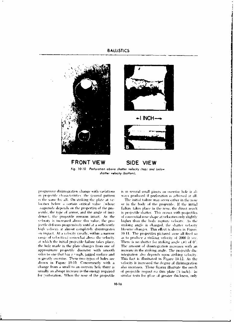
S ALLSTiCS
*-I INCH--.b
FRONT VIEW SIDE VIEWfig. 10-10 Perforation above shatter velocity (top) ind below
shatter velocity (bottom).
proigressive disintegration Ishiniu with variations is in several small piececs an oversize hole is ad-in pri je'tile ch:ira t~vristjic% the !general pattern waxs produced if perforation is achieved at all.k~ the sarne for all. On striking thet plaIte at v'e- Thc initial failuire may icchur either in the nose51locities below at c-ertain critical v-alue (whosc o~r in the body of the- projectile'. If the initial
11.L]gnitiidi' de rinds on the properties of the pro- failurt takes place in tile nose. the direct resuiltjvocile. the type of armor, and the an~Ie of inci- is projectile shatter. This occuiS with proijectilesdenee ). the projectile remains intact. As the oif convential nose shape at N-elucitiCs only sliiditlV0.1KIit% is increased abuse this valuec, the pro- higher than the body rupture -eliicitv. As tll(jet.tihe deformns progressively- until at a suifficiently strikinv angle is changed. the shatter vvh~city
high~l x-ehiii'i it almost coimpletely dlisintegrates likewise changes. This effect is shown in Figtirto n lnlpact. At it %elocity ( really. within a narrow 10-11I. The pro~jectiles pictured ývere all firedl soriligc of s cloiic s ) swilUMllShat abov, the velocit% as to prodiire at strikin~g velocity of 2000 it soc.at %shich the initial projectile failure takes place. Thlere is no shatter for striking angle 0 ) (if 0'the hole made in the plate chlanges from one of The amount of disintegration increases -with anapproximate pro~jectile diameter with smooth increase in the striking angle. The projectile dis-sides to oine that has a -)ugh, jagged surface and integration also depends upon itriking velocity.is greatly iiversize- These two types iif holes are This fact is illustrated in Fig-ure 10-12. As theshiown in Figuire 10-10. Concurrently with at velocity is increaised the degree of disintegrationchange from at small to an oversize hole there is also increascs. These fivgures illustrate the resultu1sually an abrupt increase inl the energy requiredl of piroijectile imipact va thin plate ('q' inch). infor :-erforation. W~hen the nose iif the projectile similar tests for pkwc iif greater thickness. only
10-16
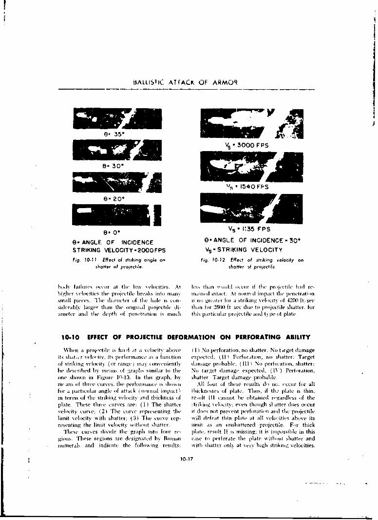
BiALLISTIC AT (ACK OF ARMOR
e). 35*
lC• rl VS 3000 FPS
e- 300
W
e. 0* Vs,- 1:35 FPS
e- ANGLE OF INCIDENCE e- ANGLE OF INCIDENCE- 300
STRIKING VELOCITY -2000 FPS Vs-STRIKING VELOCITY
Fig. 70-11 Effect of striking angle on Fig. 10-12 Effect of striking velocity onshatter of projectde. shatter -)f projectile.
bod Ifailures occur at the lo\% velocitwes. At less than ,,oul:l occur if the projectile had re-higher velocities the projectile brea1s into many m.aned intact. At normad impact the penetratinsmall pieces. Thte diamwcer of the hole is con- iv nw. grater for a striking velocity of 420n) ft, seesiderabhl, larger than the original projectile di- than for 26WXJ ft sec diie to projectile shatter, forameter and the depth of penetration is much this partictilar projectile and t% pe of plate.
10-10 EFFECT OF PROJECTILE DEFORMATION ON PERFORATING ABILITY
WVhen a prolctile is fiet c( at a vehgitv above (I) No perforation, no shatter: No t irget damageits shiat, r v.chwitv, its performance as a funltion expected; (I[I Ferforalion, no shatter: Targetof striking wehl.ity (or range) may (onvenienthy damage probable; (111) No perloiation, shatter:he describued bh mean of graphs similar to thie No target damage expected; (11) Perforation,one shown in Figure 10.13. In this graph, by shatter: Target damage p)robable.m" ans of three ctur(ves, the perforimance is shI•s•.%i All four of these results do no,, ,ccnir for allfor a particular angle of attack (normal impact t Ihicknesses of plate. Thus, if th.. plate is thin,in terms of the striking vehlocity and thickness of resuflt li cannot be obtained r,'gardless of theplate. These three curves are: (1) The shatter :triking velocity; even though sl atter does occur
e.elocity curve; (2) The curve representing the it does not prevent perforation and the projectilelimit velocity %with shatter; (3) The curve rep- will defeat thin plate at all vehs:iti,.s above itsresenting the limit velocity without shatter. limit as an unshattered projectie. For thick
These curves divide the graph into four re- plate, result II is missing: it is impossible in thisgions. These regions are designated hb Roman case to perforate the plate without shatter andnumerals and indicate the following results: with shatter only at very high strikin m velocities.
10-17
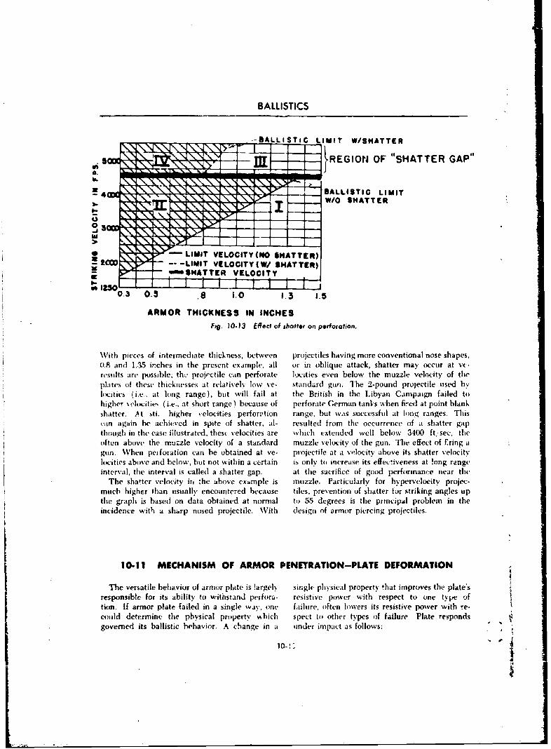
BALLISTICS
--BALLISTICLIMIT W/SIATTER
- REGION~ OF "SHATTER GAP"
LE4BLI.I II
W/O SHATTER
* - LIMIT VELOCITY(NO SWATTER)--w -IIT VELOCITY(W/ SHATTER)
*NTTER VELOCITY
ARMOR THICKNESS IN INCHESFig. 10-.13 Effect of shatter on perforation.
With pieces of intermediate thickness, between projectiles having more conventional nose shapes.0.8 and] 1,35 irches in the present example, all or- in oblique attack, shatter may occur at vc-results are potssible; th-' projectile can perforate locities even below the muzzle velocity of theplates of these thickniesses at relatively low ye- standard gun. The 2-pound projectile used bylIq'ities (i.e., at lung range), but will fail at the British in the Libyan Campaign failed tohigher velociltie (i.e., at Short range) because of perforate German tanks w.hen fir"d at point blankshatter. At sti. higher velocities perforption range, but was successful at long ranges. Thiscan again be achieved in spite of shatter, al- resulted from the occurrence of a shatter gap~though in the case filustrated. thesc velocities are which cxtendcd well below 3400 ft; sec, the
otnabove the muzzle v'elocity of astan~dard muzzle velocity of tegn h feto rngun. When peiforation can be obtained at ye- projectile at a velocity above its shatter velocitylocities above and below, but not within a (certain is only to increase its effecIveness at !ong rangeinterval, the interval is called a shatter gap. at tile sacrifice of good performance necar the
The shatter velocity if, 'he above example is muzzle. Particularly for hyperveloeity projec-much higher than usually encounrtc-ed because tiles, prevention of shatter for striking angles upthe graph is based on data obtained at normal to 55 degrees is the principal problem in theincidence with a sharp nosed projectile. With dlesign of armor piercing projectiles.
10.11 MECHANISM OF ARMOR PENETRATION-PLATE DEFORMATION
The versatile behavior of armor plate is !argelN single physical Property that improves the plate'sresponsible for itb ability to withstand perfora- resistive power with respect to one tNype oftion. If armor plate failed in a single way, one failure, often lowers its resistive power with r'e-could determine' the physical property w-hich spect to other types oif failure Plate respondsgovernied its ballistic behavior. A change in a uinder impact as follows:
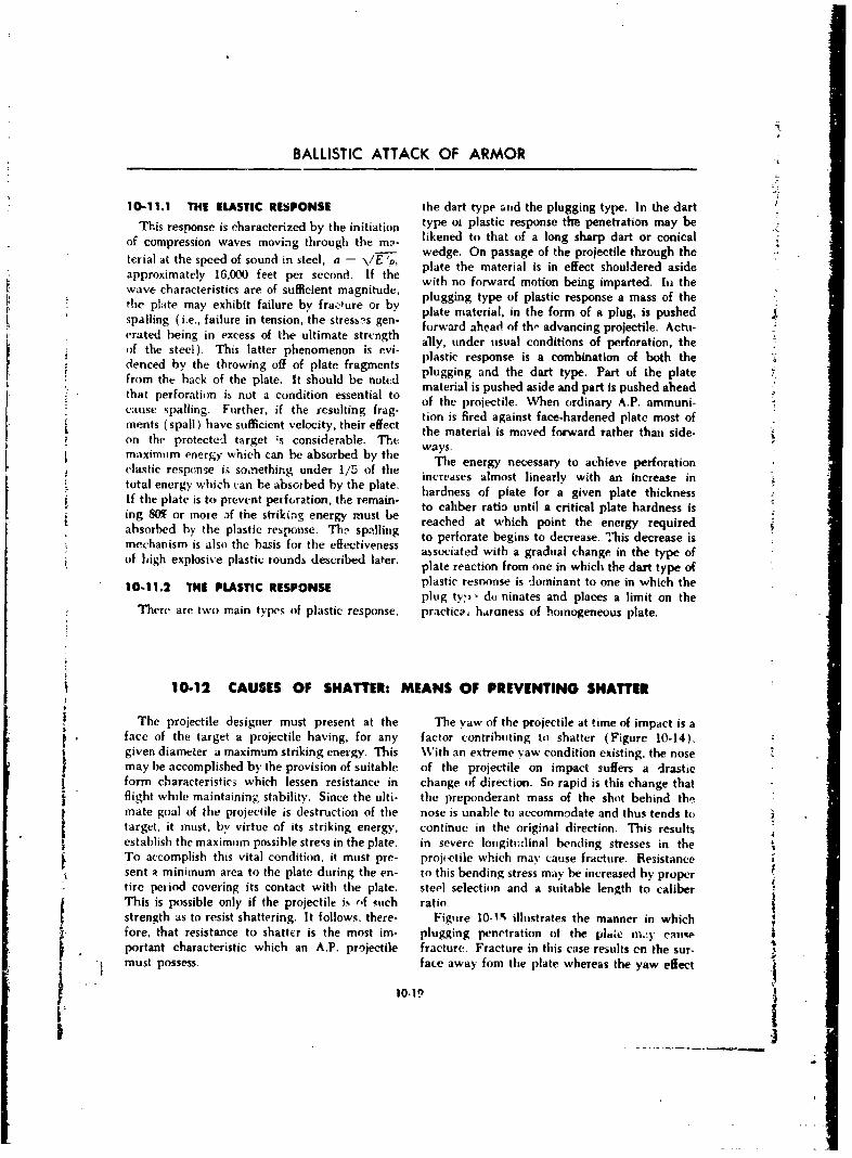
BALLISTIC ATTACK OF ARMOR
10-11.1 THE ELASTIC RESPONSE the dart type and the plugging type. In the dartThis response is characterized by the initiation type ot plastic response the penetration may be
of compression waves moving through the ml- likened to that of a long sharp dart or conicals- wedge. On passage of the projectile through the
plate the material is in effect shouldered asideapproximately 16,00 feet per second. If the with no forward motion being imparted. In thewave characteristics are of sufficient magnitude, plugging type of plastic response a mass of thethe plate may exhibit failure by fraoure or by plate material, in the form of a plug, is pushedspalling (i.e., failure in tension, the stresses gen- forward ahead of th" advancing projectile. Actu-crated being in excess of the ultimate strngth ally, under usual conditions of perforation, the
i of the steel). This latter phenomenon is evi- plastic response is a combination of both thedecf b the s teel) f o ltefagetSdenced by the throwing off of plate fragments plugging and the dart type. Part of the platefrom the back of the plate. It should be notcd material is pushed aside and part is pushed aheadS. that perforation ib not a condition essential to" eof the projectile. When ordinary A.P. ammuni-thats sl is north condiftion resseltingfalcause spalling. Further, if the resulting frag- tion is fired against face-hardened plate most ofments (spall) have sufficient velocity, their effect the material is moved forward rather thai side-on the protected target ýs considerable. Th, e ways.maximum energy which can be absorbed by the wasThe energy necessary to achieve perforationelastic resp.nse k~ somethin~g under 1/5 of the increises almost linearly with an increase intotal energy which can be absorbed by the plate. hardness of piate for a given plate thicknessIf the plate is to prevent perforation, the remain- to caliber ratio until a critical plate hardness ising 80% or more ,f the striking energy must b reached at which point the energy requiredabsorbed by the plastic response. Th,- spalling to perforate begins to decrease. This decrease ismechanism is also the basis for the effectiveness associated with a gradual change in the type ofof high explosive plastic rounds described later. plate reaction from one in which the dart type of
10-11.2 THE PLASTIC RESPONSE plastic resnonse is -dominant to one in which theplug tv,, d- ninates and places a limit on the
There are two main types of plastic response. practica, haraness of homogeneous plate.
10-12 CAUSES OF SHATTER: MEANS OF PREVENTING SHATTER
The projectile designer must present at the The yaw of the projectile at time of impact is aface of the target a projectile having, for any factor contributing to shatter (Figure 10-14).given diameter a maximum striking energy. This With an extreme yaw condition existing, the nosemay be accomplished by the provision of suitable of the projectile on impact suffers a drasticform characteristics which lessen resistance in change of direction. So rapid is this change thatflight while maintaining stability. Since the ulti- the preponderant mass of the shot behind the
mate goal of the projectile is destruction of the nose is unable to accommodate and thus tends totarget, it must, by virtue of its striking energy, continue in the original direction. This resultsestablish the maximum possible stress in the plate. in severe longitudinal bending stresses in theTo accomplish this vital condition, it must pre- projectile which may cause fracture. Resistancesent a minimum area to the plate during the en- to this bending stress may be increased by propertire period covering its contact with the plate. steel selection and a suitable length to caliberThis is possible only if the projectile is of such ratio.strength as to resist shattering. It follows, there- Figure 10-l, illuitrates the manner in whichfore, that resistance to shatter is the most im- plugging penetration of the platc mi.ty Cau114portant characteristic which an A.P. projectile fracture. Fracture in this case results on the sur- ,i • must possess. face away fore the plate whereas the yaw effect . .
10.19
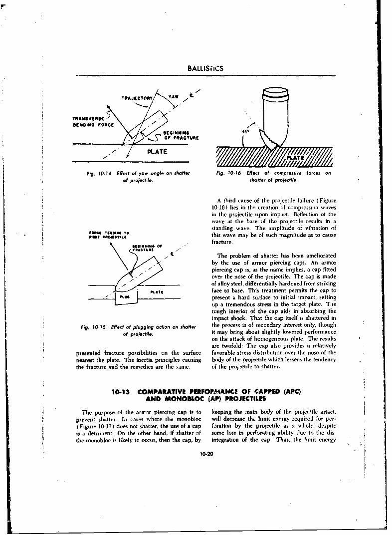
BALLISiiCS
TRAJICTONY YAW
1TRANSVERSE
SENDING FORC _\SIGINMINO 450
,t~~o,,o0 t,, \ /. I/..OF FRACTURE
- ~PLATEPAT
Fig. 10-14 Effect of yaw angle on shatter Fig. 10-16 Effect of compressive forces on
of projedtle. shaoter of projectile.
A third cause of the projectile failure (Figure10-16) lies in the creation of compression wavesin the projectile upon impact. Reflection ot thewave at the base of the projectile results in a
ST1standing wave. The amplitude of vibration oftoie rTI•IN oI To this wave may be of such magnitude as to cause
"" r[41NINee OI .OF fracture.
The problem of shatter has been amelioratedby the use of armor piercing caps. An armorpiercing cap is, as the name implies, a cap fittedover the nose of the projectile. The cap is madeof allay steel, differentially hardened from striking
p1T*1 face to base. This treatment permits the cap to" P LU present a hard su.'face to initial impact, setting
up a tremendous stress in the target plate. Tsietough interior of the cap aids in absorbing theimpact shock. That the cap itself is shattered in
Fig. 10-15 Eecd of plugging action on shorter the process is of secondary interest only, though
of projectile, it may bring about slightly lowered performanceon the attack of homogeneous plate. The resultsare twofold: The cap also provides a relatively
presented fracture possibilities cn the surface favorable stress distribution over the nose of the
nearest the plate. The inertia principles causing body of the projectile which lessens the tendencythe fracture qnd the remedies are the same. of the pro) -ctile to shatter.
10-13 COMPARATIVE PEIFOP-MANCE OF CAPPED (APC)AND MONOBLOC (AP) PROJECTILES
The purpose of the artror piercing cap is to keeping the main body of the plojet ile ,i1tact,prevent shatter. In cases where the monobloc will decrease thL limit energy required for per-(Figure 10-17) does not shatter, the use of a cap faration by the projectile as a -hole. despitcis a detriment. On the other hand, if shatter of some loss in perforating ability 'ue to the dis-the morobloc is likely to occur, then the cap, by integration of the cap. Thus, the !imit energy
10-20
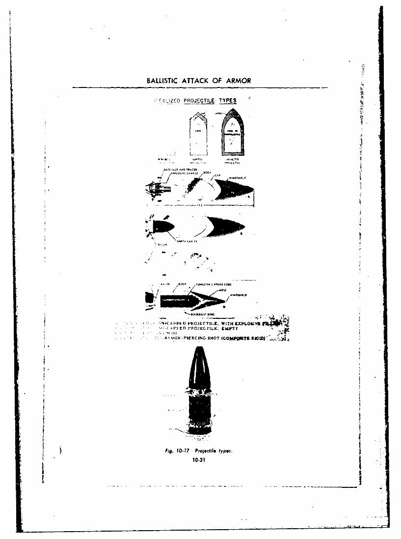
BALLISTIC ATTACK OF ARMOR
r-t-!ZE PROJECTILE TYPES
K0D
R t1*
A OK-sO4AIE INGSHT CO
1-21
BALLISTICS
TABLE 10-1 COMPARATIVE RESISTIVITY OF ARMOR PLATE
Thickness of Homogeneous Armor Plate (Inches) Defeated by
AP Shot Fired at 2800 ft 'sec Muzzle Velocity
Obliquity
Range (Yards) Striking Velocity . . . .. .60a 550 300 200 00
0 2800 3.2 4.2 5.0 6.2 6-750k) 2680 2.9 3.5 4.5 6.0 1 6.5
1000 2570 2.7 3.3 4.3 5.7 6.21500 2460 2.2 3.2 4.2 5.4 6-0.100 2140 1.4 2.6 3.5 5.0 5.3
Comparative Thickness of Homogeneous Armor Plate (Inches) Defeated byProjectiles Fired at 1000 yds Range
Obliquity
Round Muzzle Velocity Shell Velocity I .. - .......-... . .. .- .600 550* 30* 00
APC 2800 2560 1.9 2.5 4.7 6.1HVAP oj) 3350 2850 1 2.1 2.9 7.8 10.2HVAP (2) 3850 3200 2.9 3.3 I 8.8 11.2
may be either increased or decreased by the higher range of 40' and up, monobloc projectiles
"attachment of a cap, and unless the conditions of perforate a greater thickness of armor. The ap-
impact are specified no answer can be given to parent superiority of monobloc projectiles at
the question of whether a capped or a monobloc greater obliquities results from the tendency of
projectile perforates a greater thickness of armor. the monobloc nose to shatter causing the remain-der of the projectile to tip more nearly normal to
Recent findings based upon scale model firing the plate. Perforation is achieved by punchingtests show that capped projectiles surpass mono- action in spite of partial shatter of the projectile.bloc projectiles for attack of heavy hamogeneous In this obliquity range the capl,.ýd projectile hasarmor in the obliquity range of 00 to 40'. In the a strong tendency to ricochet.
; t
10-14 PERFORMANCE OF JACKETED PROJECTILES
10-14.1 COMPOSITE RIGID TYPE carbide core, or subprojectilc, enables the missile
SIn order to take advantage of the increased to derive the full benefit of the propellent gases.: striking energy made possible by the use of a Further, since the jacket or carrier is generally
smaller caliber, higher velocity perforating mis- made of aluminum, the lighter overall weight ofsile, designers have made use of the principle of the complete projectile coupled with the use of
the subprojectile as shown in Figure 10-17. Here high potential propellants results in a higher
the jacket around the smaller caliber tungsten muzzle velocity. The decrease in overall weight,
.1022
BALLISTIC ATTACK OF ARMOR
while helping to give greater muzzle velocity, tapered bore guns and also increases tremen-also results in a lower inflight ballistic coefficient, dously the time and costs ot production of bothC, than is found in the discarding sabot type of gun and ammunition. In addition the tube isround. Such projectiles, hypervelocity (HVAP), short lived. The Cermans made use of this prin-are fired at high muzzle velocities (above 3500 ,iple, however, in some of their weapons.ftsec). They have excellent armor piercing 10-14.3 DISCARDING SABOT :qualities if used at normal battle ranges, how-ever, their armor piercing abilities fall off rapidly In the discarding sabot type of armor piercingat longer ranges due to the low ballistic co- projectile (Figure 10-17) the jacket or carrierefficient. Since the jacket of this type projectile falls away from the subprojectile or core whenis rigidly attached to the core (which has a the projectile leaves the muzzle, allowing thediameter about half that of the gun) and does tungsten-carbide subproject'ie to proceed towardnot fall off until in contact with the target, the the target. Since the diameter of the core isHVAP projectile is also known as the composite approximately half that of the complete projec-rigid or cotnpo-rigid type. tile, and since the carrier is made of a light metal
such as aluminum, the overall weight of the corn-10-14.2 FCWING SKIRT PROJECTILES posite missile is much less than that of a mono-
(TAPERED BORE) bloc projectile of the same caliber. Consequently,
This type of projectile (see Figure 4-17) is the muzzle velocity of the missile will be greaterfired through a tapered bore which may either than that of a monobloc projectile of equal cali-be built into the gun or which may be added to a ber. Since the smaller subprojectile presents astandard gun by means of a special muzzle at.. smaller area to be retarded bv air while on itstachment. The taper serves to swage down the way to the target, its ballistic coefficient C willflanged skirts which extend from the main body be high and it will have a low rate of loss ofof the projectile as a jacket As a result, the muzzle energy, arriving at the target with a highemergent caliber is much less than the original striking energy. As a net effect the subprojectilediameter. In this way, the accelerating pressure is effective over a much longer range than theof the powder gases acts on a large area in the composite rigid type.gun bore, while a small (emergent) area is pre- The principal disadvantage of the sabot typesented to the resisting pressure caused by" air is the danger that discarding oieces of jacket mayresistance in flight. This type of projectile has, strike friendly troops. Another important short-therefore, the advantage of good exterior ballis- coming is that the sabot is not always uniformlytics from the standpoint of ballistic coefficient.However, the swaged down skirts make imperfect discarded at the muzzle resulting in deflectioncontact with the projectile body thus creating of the projectile from its flight path. Further en-generating points for retarding shock waves at gineering sudies are being conducted to improvehigh velocities, There are two other serious dis- uniformity of stripping the jacket from the sub-advantages of the folding skirt type. The taper projectile with marked improvements in tech-prohibits the use of standard ammunition in niques foreseeable.
p 10-15 OVERALL COMPARISON OF ARMOR-PIERCING PROJECTILES e
The foregoing discussion of the various types sufficiently Versatile that we can afford to elyof armor piercing projectiles should not lead to completely on it,thp conclusion that any one type is so much bet- For example, the tungsten-carbide cores ofter than all others that it can completely replace composite rigid projectiles are readily fracturedthem. Each type possesses certain advantages by skirting plates set at high ollievaities in frontwhich under favorable conditions make it the of the main armor. In addition, it should bewbest for those conditions. No one of the types is pointed out that the superiority of performance
10-23
-~ .4
BALLISTICS
of this type of projectile over steel shot bodies is plate at high angles of obliqaity. As a result ofgreatest in ihe short range attack of greatly over- these firings an experimental- monobloc projectile
matching face-hardened armor plate at low oh- formed by cutting off the nose of a standardliquity. The trend toward very high obliquity, monobhlo and adding a windshield has been pro-longer range attack of faster tanks, having more doced in limited quantities for further trial.
a'early matching homogeneous steel armor pro- When the whole situation is summed up ittected by skirting plates, is accompanied by a amounts to this: we need all types of projectiles;marked decrease of the formerly great superi- armor piercing (AP), armor piercing capped
ority of the HVAP projectile. (APC), composite rigid (HVAP), discarding
Recent comparison firings of AP, APC. and sabot (DS), shaped charge (H.E., A.T.) andIHVAP projectiles indicate that the AP (mono- new classified types. Any of these would be theblocI shot is consistently more effective against best round for the particular type of structurerolled, cast homogeneous, and face-hardened which it was designed to meet.
10-16 CHEMICAL ENERGY PROJECTILES
10-16.1 HISTORY greater effect on steel plate than solid blocks of
this material. While considerable time elapsedThe discovery of what is now variously re- between the publications of the work of Munroe
ferred to as the shaped charge effect, Vie hollow and that of Neumann, it is generally believedcharge effect, the cavity effect, or the Munroe that the same conclusions were arrived at idc-
effekt, dates back to the 1880's in this country. pendently by each investigator.Actually, the essential features of this effect had to the start of World War II, the openbeen obhserved about 1800 in both Germany and literature contains precious little on the subject.Norway, although no great use was made of it In fact, it was not until about 1940 that we hearand it was temporarily forgotten. of it again in this country, at which time a Swiss
Knowledge of the shaped charge in this engineer, fI. A. Mohaupt, brought over the ideacountry stems from the work of Dr. Charles of a projectile carrying an explosive charge in thc
Munroe, who, while working at the Naval Tor- form of a hollow cavity. Research work in this
pt-do Station at Newport. Rhode Island, in the country probably stemmed from t0is id.-a, in1880"s, discovered that if a block of gun cotton which thin-walled steel cones of 45' apex anglewith letters countersunk into its surface is deto- were used as liners for the cavity. A grpatl% in-
tiated with its lettered surfacc against a steel tensified program of research on this subject wasplate, the letters are indented into the surface of promptly initiated by the Ordnance Departmentthe steel. and it was not long before a number of labora- "
Apparently nothing was done toward further tories over the country became engaged in study-study of this eff oct. but between 1910 and 1914. a ing both the theoretical and l)ractical aspects ofnumber of German patents were granted for the the phenomenon. It should also be noted that by
application of what essentially was the hollow the late 1930's. the Germans had become consid-charge effect. Particularly notable was the work erably advanced in their study of this phenom-of Neumann, whose work was based on tests enon, and it is nmw known that this work was
made using blocks of TNT having coniLal inden- considered to be of such importance as to b)ctations. He found that such blocks produced a classified as top secret.
10-17 TH7 SHAPED CHARGE PRINCIPLE
Up to this point, we have discussed the prob- which force their way into the target materiallem of penetration and perforation by missiles and are designed to emerge undeformed at the
10-24I
BALLISTIC ATTACK OF ARMOR
HI$4.jXPLQFtVýtANTITANKJMHJSL
Fig. 10-18 Shaped charge (high explosive, antitank shell).
inner face. In such cases the undeformed missile the outer face of the target, producing a jet
is the instrdmcnt of damage, and the degree of which is the instrument of damage.
damage is dependent or. the striking velocity of A shaped charge missile consists basically of a
the missile. The shaped charge rr.issile differs hollow liner of inert material, usually metal and
from the types of armor piercing projectiles al- of conical, hemispherical, or other shape, backed
ready discussed, in that the thickness of material on the convex side by explosive. A cor.ainer and
it can perforate is essentially independent of its a fuze and detonating device are included
. striking velocity. In fact the missile remains at (Figure 10-18).
10-17.1 FUNCTIONING collapse. The charge was 50 '50 pentolite having
When this missile strikes a target, the base fuze a base diameter of N inch. The time noted in
operating on the non-delay or inertia principle, microseconds for each radiograph denotes the
detonates the charge from the rear. A detonation time after the detonation wave passed the apex
wave travels forward and the me~al liner is col- of the cone. The jet breaks up into fine particles
lapsed starting at its apex. The collapse of the early in the process of its formation, but retains
cone results in the ejection of a long, narrow jet its jetlike characteristics. There is a gradient in
of the products of explosion and metal particles the velocities of the particles along the jet. The
from the face of the liner at velocities from 10,000 particles in front move faster than those in the
to 39,000 ft'sec. This process is illustrated in rear causing the jet to lengthen, and thereby re-
Figure 10-19 by the series of ultra high speed ducing its average density with time. The jet is
radiographs of an experimental shaped charge followed by the major portioa of the now com-
lined with a 45' steel cone, radiographed at suc- pletely c-llapsed cone. The latter is generally
cessive times to depict the mechanism of cone referred to as the slug.
10-18 THE THEORY OF JET PENETRATION
When a jet strikes a target of armor plate of The difference in diameter between the jet and
:mild steel, pressures approximating 2,50,000 at- the hole it produces depends upon the charac-
mospheres are produced at the point of contact. teristics of the armor plate. Thus a larger hole
This pressure produces stresses far above the is made in mild steel than in armor plate. How-
yield strength of steel and the target material ever, the depth of penetration into a very thick
flows out of the path of the jet as would a fluid, slab of mild steel will be only slightly greater
There is so nuch radial momentum associated than that into homogeneous af mor.
with the flow that the diameter of the hole pro- As the jet particles strike they are carriedduced is considerably larger than that of the jet. radially with the target material. The jet is used
10-25
L
BALLISTICS
IIP
36 P1'N
Fig. 10-19 Ultra high speed radiograph of shaped charge detonation(jet moves from right to left).
tip fPoin tht froiit and becomes shorter and difference in the primarN penetratiooitas well.shorter tintil finally the last jet particle strikes Since the !strzssses produced by the jet are muchthe target and the primary penetration process greater than the vield strengths of most target
stop. Te acualpentraton ontiuesfor materials, both the target and the jet can he con-short time after vessat~on of jet action because sidered as fluids.the kinetic energy imparted to the ..trget mateýrial Wh~ile sorme exception. will he found to the foi-by the jet inust be dissipated. T he additional ]wn ue h et fpiaypntainPpeerto ccatised by this afterflow is called lewengdul,; tedpho primaril peneerl a tora:tiolngthpeodr enetration. depnd prgnarule ondeerlfptosntedentsecodar peetrtio. Is mgniudedepnds of the jet. L, the density of the target material,Opon target strength. It is mainly responsible for p;aid the average density uf the jet, p,. Actu-the small differences obscrved between the ' -dlepths of penetration in mild steel and in homo- ally it has been found that P' is proportioned to
geneous armor, although there is probably some L vp'
10-26
BALLISTIC ATTACK OF ARMOR
burotft _(a) Hollow charge and explosive train prior toTCharge initiation of explosion.
(b) Hollow charge undergoing process of a high--------------- explosion. The detonatiqn wave initiated by the
-* •detonator and booster hns passed over most of the..... -liner which is in the process of collapsing to form
the jet and slug. At this stage, the principal linerDetonation Wa.0 mass in the jet has been formed from the apex of
the liner.
A.
Detonation velocity(c) Relative velocities of jet, liner, and slug particlesduring the process of cone collapse would be as
Relativt Slul Velocuty O Selatv* ,jet Veiocity observed from a moving point, A, based an equatinghorizontal components of momentum about A. Notethe relative h.gh jet velocity and motion of particles
of the liner towards point A.
Fig.10.20 Jet penetration.
The strength of the target material does not UND. OFAue. 10919seem to have any appreciable effect on the depthof primary penetration, however it should ben•tted that the jet density, p,, is dependent to alarge degree on the density of the cone, particles i I I
of which are dispersed throughout the pu'imary , ajet. As iliustrated in Figure 10-20 (a) (b) (c). 4the ,'one tends to invert in the early pro4 ss of •jet formation. Security restrictions limit discus- •sion of developments sv cone design and con-figuration, however certain basic parameters andvariables affecting jet performance are indicated YPIOAL OmATIM IN M LO GTI6LP"COUNDSTSPA ItM41011i "Mt • FNOin the following paragraphs. W MA O arniE 11111. *U1ML o0A1NO9P
"The standoff distance is defined as the distancefrom the base of the cone to the surface of the Fig 10.21 Dependence of penetration on sf.,dofftarget when the detonation occurs. This distance c
is extremely important in obtaining maximum
penetration of the jet. An increase in standoff of primary penetration. This is true up to adistance allows an increase in the length of the certain distance. Beyond that distance the jetjet L, but at the same time decreases the average spreads somewhat due to irregularities in thedensity p, The product of these two quantities cone and charge, which decrease the depth of
r s substantially nstant, so that from the primary penetration. Examination of Figure 10-reinit would appear that an 21 will show clearly how penetration varies with
"increase in standoff distance increases the depth standoff distance.
10-27
rr
BALLISTICS
TABLE 10-2 IXPLOSIVI PENETRATION POWER
Density Deltonation Rate Relative Standing inExplosive (graims el (m 'sec) Penetration Ffficiency
Coip B 1.68 8000 IstPentolite 1.64 74140 2ndEdnatol 1.62 75N) 3rdTNT 1.59 6900 4th
TABLE 103 LINER MATERIALS
Approx Sp (r Hole Depth. Hole Width,
Meald Group of L.iner .letal rm, m nn,
('opper and co'£pper alloy,, 8.5 58 14
Deeip drawing sheet steel 7.7 5.5 15Zinc 7.2 5I1 17Sheet iron 7.8 .17 16Aluminum aid its alloys 2*7 "2. I 3Mlagrusiun alit v, 1.7 23 25
10-19 FACTORS AFFECTING PENETRATION BY IAPED CHARGE PROJECTILES
The critical factý)rs affecting pt.,itration bv shaped chartge missiles are as follows:
10-19.1 TYPE, DENSITY, AND RATE OF The net effect of confineir.t is to increase pene-DETONATION OF EXPLOSIVE tration by 10 to 1'5.CHARGECHARE t10-19.3 DIAMETER AND LENGTH OF
While the depth of penetration is indicated CHARGE BACK OF LINERto be mor. closely related to detonation pressurethan to the rate (if detonation, it :nav he said The length of the charge should be at leastthat the greatest effect will be produced by that four times the diameter. The iminroc effect isexplosive having the highest rate of detonation, not dependent on the presence of a liner (i.e.,Tahle 10-2 illhstiates the relative effect of four paper ('culd be iised to form the contour of thudifferent ca~table explosives. explosive I hut the material of the liner actually
While the rate of detonation is of prime irn- contrib,,tes in a large measure to effective per-portarnce in selecting a high explosive filler, other formance, penetration being a function of p,.propertisi of the explosive must be taken intoctsideration. mo10-19.4 LINER MATERIAL AND THICKNESSconideatin.Among these are sensitivity to
initiation, pourabihty, and thermal stability. The type of metal used for a liner and thethickness of this metal li,,er have also been foLnd
10-19.2 CONFINEMENT OF CHARGE to affect the penetrating action of a given shapedConfinement is inherent in a military projec. charge. Cones of differer.t wall thickness but all
tile. Its effect on shaped charge action is to de. of 90)' apex angle were prepared from each ofcrease loss of pressure laterally, increse the approximately twenty different metals and metalduration of application of pressure, and p:obably alloys. All the charges were fired at a constantto improve the shape of the detonation front. standoff. The data given in Table 10-3 are based
10-28 -0.
I
BALLISTIC ATTACK OF ARMOR
on the hole depth an,] width ohtained with the 10-19.7 ROTATION OF THE MISSILEcharges employing hine.s 1 into in thickness. It Particles making up a jet are given a tangentialwvas found, at least ia this series of tt-sts, tiat velocity due to rotation of the missile during for-the depth of penetration of charges prepared mation of the jet. This tangential velocity corn-using cones of each of the differeni -netals in- punent causes spreading of the jet and thereforeereased( with liner thickness up to , mn, and lessens penetiation. Projectiles having conicalthat further increases in liner thickness beyond liners may h'se as mu h as 50M or more of theirthis had no appreciable effect o, the depth of effectiveness due to rotition. Projectiles havingpenetration. hemispherical liners are somewhat less affected
Seveial points shh( he inoted tinthese dat. by rotation because of the difference in theFirst, the depth of penetration appears to be r,,- mechanism of liner collapse and the greater masslated to the specific gravity of the liner metal, of the jet. In general, penetration is reduced asSecondly, there was no appreciable difference in spin increa -s from 0 to about 200 rev/see, afterdh penetrating power , biarges employing which furtier spin has little effect. As is alreadycones of metals within the same group, i.e., cop- known, artillery projectiles require rotationper and copper alloys. Thirdly, as the depth of (aboat 10.000 rpm) for stability and co'ie-
penetration decreased, the width of ,he hole in- quently the effectiveness of shaped charge roundscreased, so that the hole volume in all cases was is considerably reduced. Thk rotational velocity,practically unchanged. These results were ob. has less of a detrimental effect on depth of pene-tamed under a given set of conditions. A change tration if standoff distance is small.in these conditions might well alter the relative
eff(-tiveiess of cones prepared from different 10-19.8 ANGLE OF IMPACTmetals. For each type of shaped charge projectile there
For specific applications, such as static demo- is a critical angle of impact beyond which depth
lition charges, glass liners are utilized because of penetration is markedly reduced and is non-the performance of such liners insures more cvlia- uniform from round to round. This is primarilydrical holes for the insertion of an additional due to variability of performance resulting from
standard charge, and also because the possibility fuze action.of a hot slog being w2dged in the hole cannot 10-19.9 STANDOFF DISTANCEbe tolerated. For a given shaped charge projectile one of
10-19.5 INCLUDED ANGLE OF LINER the most important factors governiner depth of
Amcrican ammunition varies fromi 42^ to 60 penetration is the standoff distance. , roper pro-Foreign amnmunition varies from 18"- to 90' jectile design providing correct standoff distance
allows sufficient room for the fuze to function10-19.6 LINER SHAPE properly and the cone to collapse and form a jet
Different shaped cavities and liners react in of proper density, thus maximizing the possibility
different ways. For example, a conicil liner col- of perforation of the target. Factors such aslapses from the apex and leaves approximately proper striking velocity, resistance offered by the70 to 80• of the liner to follow behind the jet as material of which the round is -! .de, variance
a slug. Hemispherical liners on the other hand of density of the jet due to rotation of the pro-appear to turn inside out, most of the liner being jectile, plus other variables must be considered.
projected in the jet, with only random bits of Failure to consider all factors affecting the for-residue left behind. The jet velocity from hemi- mation of the Eigh pressure high velocity jetspheres is only about !4 that from cones, but the would materially affect sound performance. Fig-
mass of the jet is approximately 3 or 4 times as ure 10-21 shows typical craters produced in mild* great, with the result that total jet energies are stcel by static oharges fired at various standoffs.
"comparable. The only standard round of am- Depending upon liner shape, liner material, andSismunition designed with a hemispherical (or lack of spin, up to six times the cone diameter
modified hemispherical) liner is the 57-mm re- may provide optimum standoff distance.eoillkss rifle. All other types employ a conical The dependence of best performance on stand-shape. off distance poses a fuzing problem, especially
10-29
.4
BALLISTICS
in the case of rotating, shaped charge, artillery strength and length, fuze time, and others. It ispro;ectiles. Conventional at tillery wea[..)ns nut intended to throw confusion into an under-normally impart a higher muzzle velocity to pro- standing of the action of shaped charge arfmuni-jectiles than is desirable for shaped charge prm. tion b% meintioning variable after variable, hutjectiles. IHigh striking velocities of shaped clargc to point out strongly that the design, coiistruc-projectiles may result in the collapse of the hat tion, and action of such 'iilnition is by nolistic cap upon impact. If the projectile is fuzed neimns simple but rather is a co-iiplexity of gov-with an inertia type base fuze, the time necessar' erning factors, each of which has its ,,vn sig-for the fuze to initiate the bursting charge ma• nificant effect.permit an appreciable decrease in the standoff Involved in the internal construction of shapeddistance as the cap collapses. In order to oer- charge ammunition, there are a number of fac-come this condition, some recent designs have tors which have an adverse effect on penetratior.provided a nose instantaneous fuze to initiate the Among these might he mentioned ( 1 misalign-detonation of the charge. Since, with this type nient of explosive charge axis with cone axis;of missile, the charge must be initiated at the rear (2) metal liners of uneven thickness; (3) fern.a-in order to provide a proper dirueticnal impulse tion tif an uneven later of explosive around thefor the detonating wave, the liner must be open *base of the cone; and (4) cavities or Fw (densityat the apex and 'lhe bursting charge must have areas in the explosive charge. It is known thatan open channel in it to allow the wave to reach ;ry one of these may cause either poor jet F',rthe booster at the base of the charge. This axial loation or else a jet which tends to go offvoid does not adversely affect either the detona- obliquely from the extended cavity axis. Par-tion wave or the collapse of the liner. On the ticular mention might he made of the neessitvcontrary it appears to slightly enhance effec- of using an explosive filler having good ftliidtvtiveness of the ch:,rge due to forming a some- when casting into the component. A castablewhat concave detonation front. explosive which has a high viscosity or which
tends to be mushy even at the high temperatureof standard melt kettles, may solidify too quickly
10-19.10 DESIGN AND MANUFACTURING when poured into the shaped charge cavity andPROBLEMS thus not form a perfect layer around the has(,
In the design of efficient shaped charge am- of the cone. The adverse effect of poor loadingmunition, still more variables must be taken into is nore apt to he noticed in the performance ofconsideration, such as shell wall thickness, ogive small weapons than in larger calibers.
10-20 PERFORMANCE OF SHAPFD CHARGE MISSILES
The fact that performance of shaped charge Various theories have been offered as to whatmissiles is independent of striking velocity as happens inside a tank perforated by the jet ofsuch, and therefore of range, would appear to a shaped charge missile. Tests quite definitelymake these charges ideal for antitank artillery, show that for shaped charge missiles having ex-However, as previously noted, when shaped plosive charges weighing 15 pounds or less therecharge missiles (H.E., A.T.) ar.- caused to ro- is no appreciable blast effect, pressure rise, ortate by thc rifling in the guns from which they temperature rise inside the tank. The jet doesarc fired, their performance drops 30 to 71T. nor spuead out in a cone shaped spray frotm itsNon-rotated, fin stabilized, shaped charges c-n exit in the armor plate. If the jet perforates thebe made to perform almost as wel! when deto- armor plate with sufficient energy to spare, itnated b) impact as when detonated statically, does continue along its original path. Ammuni-providing the striking velocity is not sc great that tion, fuel, etc., in the path of the jet will oftenthe operation time of the fuze will allow the cone be set afire. Crew members in the path of theliner to become deformed before complete jet will be severely injured, but it is entirely pos-detonation. sible for one man to he severely injured or killed
10-30
L.!

BALLISTIC ATTACK OF ARMOR
and the man immediately adjacent to him, but mor plate and upon the amount of explosive in.
out of the path of the Jet, to escape unscathed. the charge, varying amounts of metal may be
It is entirely possible for a tank to be perforated spalled off the rear face of the armor at suE-
from such an angle that no harm results to the ciently high velocities to injure crew members. A
crew or tank except for a small hole in the armor. Fire very often results because the crampedspace and very large amounts of explosives and
Damage is actually produced by the tiny, hot, inflammable fuels make it highly improbable for
high velocity fragments of liner metal making up a jet to perforate a tank without striking suchthe jet. Depending upon the quality of the ar- inflammable material.
10-21 HIGH EXPLOSIVE PLASTIC PROJKCTNUS
The high explosive plastic projectile is pri- struck by kinetic energy rounds (a compressivemarily an antitank round which uses a corn- wave traveling through the steel at the spv--1 ofparatively new principle to defeat armor. The sound in that material). This round is also veryspalling or chipping of the interior tank surface effective against concrete, timber, or log barri-caused by this round is completely effective with- cades and bunkers. Its fragmentation also makesout necessarily penetrating the exterior surface. it a useful antipersonnel round. Like the H.E.,The projectile achieves maximum efficiency A.T.-T. round, it is equipped with a base detonat-against sloping armor rather than vertical at- ing fuze containing a bracer element. Perheam
mor; however, specific test results indicate that the greatest reason for developing this type roundin the region of slope of 100 or less, the round is the excellent antitank protection provided totends to separate or splatter upon impact. Like- crews of low muzzle velocity weapons firing
wise, a region of poor performance lies at very spin stabilized projectiles. This was and is ofhigh angles of obliquity where the explosive particular importance until more effective guntends to form a drop.shaped pattern or wipe off launched fin stabilized H.E.,A.T. rounds arethe surface, thus effectively reducing the strength developed. The H.E.P. round may be spinof the shock sent through the armor. Because stabilized without detrimental effect on its per-of its characteristic plastic filler (Composition formance against armor and is particularlyC4 or A-3). this round has a tendency to spread well suited to low muzzle velocity consistent withou' over tht target surface on impact. Detona. accuracy. H.E.P. rounds have currently beention of thf explosive charge sets up shock waves added to the family of ammunition available forwhich cause the spalling effect which is analo- standard and developmental weapons; howevergous to the description of elastic response de- the hit probability and performance against ar-scribed as a characteristic response of armor mor, particularly low quality armor, is classified.
10-22 BODY ARMOR
The tse of armor as a defensive means for the became a fixture in World War I, but the pro-individual is as old as the history of armed con- posed body protection devices (mostly con-flict. The helmet, the shield, and body and limb cerned with overlapping platelets fastened to acoverings were natural sequels to the develop- fabric backing), goggles, and even aviator hel-ment of sword, spear, sling, and bow. Modern mets were rejected on the basis of immohiliza.history, following the development of firearms, tion of the individual. -records the sketchy and experimental use of body During 1943, the aerial offensive against Ger-armor during the American Revolution, Na- many resulted in high casualty rates resultingpoleonic Wars, and Civil War. The stamped from attack by fighters mounting 20-mm aircraftstecl helmet (manganese alloys) appeared and cannon with high explosive shell, and from H.E.
10-31

BALLISTICS
antiaircraft attack. From the body armor designs dividuals from a cal. .45 bullet fired at point-of World War I, the flak suit for bomber crews blank raage. Such types include the doronwas further developed and placed in production. jacket. IZ consists of a cotton jacket r-cvcred onExperience with helmet design, body aprons, the front and back with pockets intc which aevests, groin and crotch armor, eye armor, and inserted flat rigid panels. The panels, about one-nick armor revealod the desire of combat crews eighth inch thick and of -various shapes to matchto wear the protection afforded and brought the confoimations of the body, are made of lami-forth new techniques, with resultant weight say- nated layers of glass fiber and plastic. Anothering that appealed to the ground combat units, type is more flexible than t*'te doron jackets, be-Korean fighting records extensive use of armored ing made of layers of nylon fabric pressed to-clothing for protection against low velocity shell gether. Field testing of both types was conductedfragments and small Prms rounds which have lost with and without a sponge rubber layer on themost of their velocity, inside next to the body.
Materials used in combination to produce in- Additional protective devices include seat ar-dividual armor include Hadfield manganese stee! mor for Army aircraft which is made of a nylonfor helmet and overlapping platelets (2 in. laminate and permits the pilot 'o wear his para-square); silk and synthetic plastics which offer chute on his back. It affords a degree of pro-light weight and strength combination foe layer te-tionu from ground fire for both the chute andthickness required; aluminum plates with nylon himself.pad for 20% weight savings over steel plates for Eye armor consists of a thin steel sheet cover-the same protection; Y-inch panels of laminated ing each eye, mounted in a rubber dust gogglelayers of fiberglass and plates which can be in- frame. E-ach shield is pierced by vertical andserted in enlarged pockets of cotton or nylon horizontal slits intersecting in front of the eyevests and jackets; and laminated plastic for hel- pupil. A third slit descends at an angle from themets which serve as crash protectors and armor inner corne" of the eye. This design permitsfor tankers and crews similarly equipped. good visibility and at the same time affords pro-
The most recent developments will protcct in- tecUoon from small missiles.
REFERENCES
No general, unclassified references are available.
10-32

APPENDIX A 4
INSTRUMENTATION
A-1 INTRODUCTION
Instrumentation is the science of gathering and parameters. To make these measurements sig-evaluating data derived from testing actual nificant and accurate is often a complicated andpieces of equipment. As weapons of war have difficult problem of data processing. The databecome more expensive and complex, it has be- recor¢ed by the instrumentation systems are nut
. come necessary to make instrumentation cover- often in immediately useable form. Data areage more comp1,•te and exact than was formerly recorded on motion picture film, magnetic tapes,necessary. The only reason for testing is to de- hand-written logs, oscillograph paper, or evenvelop an operational piece of equipment and un- in the memory of human observers. Recordedless we find out early in developmental progress data in such preliminary forms are called raw
Swhere the areas of weakness are the equipment data. The process of translating such raw datawill never function properly as a system. In into a numerically correct and analytically use-guided missile test work, it is necessary that any ful form is called data reduction. The result ofcomponent failure detected in one test be de- and purpose of data reduction is the productiontermined immediately so that it may be corrected of final data. Final data are those from which allprior to subsequent testing. Similarly, in the predictable errors have been removed and fromdevelopment of new types of projectiles, all which all possible unknown errors have beenflight parameters (muzzle velority, acceleration, corrected by statistical methods, and which areattitude (',aw), striking velocity, etc.) must be then presented in a form suitable fo, analysis bydetermined if we are to properly understand its the test engineers.functioning and therefore intelligently improve This discussion will be primarily restricted toits performance. The more information available instrumentation techniques used in irterior bal-the better so long as the scientific value is coin- listics and exterior ballistics, therefore will bemensurate with cost of equipment required to only a very limnted treatment of a vastly im-gather these data. portant subject, as can be realized when the
Instrumentation techniques fall into two very necessary instrumentation in the guided missilebroad and general categories, onboard or out- and atomic energy test programs are consiiered.side the vehicle. For equipment of sufficient size Instrumentation techniques are needed to meas-it is possible to instrument component function- ure the various performance characteristics ofing and overall performance by internal sensing a projectile (whether it is a bomb, rocket, bullet,devices, the readings of which may either be or artillery shell). Measurements during thetransmitted by radio to an outside receiver or powered phase (within the gun tube or laurcher,recorded directly on some recording instruction or during the motor burning time) deal with in-carried internally for post tert recovery and play- terior ballistics. Measurements made while theback. For test objects ,-f insufficient sizc or projectile travels to the target gather informationwhose performance environment makes internal on its exterior ballistics. Information gathered asinstrurnentation difficult or impossible, external the projectile accomplishes its terminal missionmeasurements must be made, using optical or at the target is gathered for the so-called pene-electronic techniques. tration ballistics. Therefore, for each of the
":•-ae purpose of all instrumentation is to gather three phases of a projectile's flight life, instru-quantitative and qualitative data. Mere obser- mentation for data collection must be providedvation may provide data, even adequate and use- if the ordnance item is to be proved or ire-ful data. Generally, however, instrumentation proved.
is intended to provide measurements, that is ac- Increasingly finer instrumentr have helpedtual numerical values for critical performance considerablv in ballistic research. The LeDuc
A-1
BALLISTICS
equations as presented before have been checked measured -with great precision and expediency;and corrected to a fair degree of accuracy by bet- therefore, a multitude of devices such as record-ter instruments. In the testing of new ammuni- ers and gauges have been developed which con-tion or powder, or in the development of new vert various physical phenomena into electricalweapons, it is necessary to know velocities and impulses. The choice of device to make thepressures under firing conditions. As an exam- measurements desired depends upon the physi.pie, in determining a powder charge for a heav- cal quantity involved, its operating environment,ier than standard I rojectile to be fired in a the engineering objective, the accuracy desired,particular gun at the same muzzle -velocity as the frequency of measurement desired, reliability,the standard projectile, it is necessary to know funds available, equipment available, datahow the pressure varies within the bore due to processing facilities, time available, and many, the neessary increase in charge. Successive in- other factors. The consideration of these factorscreases in charge P~re made and their pressure-cdin the selection of appropriate physical appara-travel curves taken using one of several types of tus, accepting a reasonable compromise accord-pressure gauges. From these curves can be de- to conomics a the m prome oectivetermined the proper charge and the proper ing to economics and the measurement objective,
granulation to be used. is the science and art of instrumentation.Measurement of a phenomenon requires first Briefly then, instrumentation requires a device
that a device be utilized to convert this phenome- to eetect the phenomenon being measured andnon into one for which measuring equipment then a device to record it for detailed analysisexists. Electrical voltages and currents can be and compilation of useful data.
A-2 TELEMETRY
The most important and most widely used type (g) Recording equipment.of internal instumentation is telemetry. The (h) Demodulators and decommutators.field of telemetry concerns itself with measuring (i) Data display equipment (See Figurevarious parameters during flight or operation and A-1).displaying the data at a ground or other remote Such a system of instrureentation is of great
: station. The link between the missile and the value since test data are available for analysisreceiv:ng station may be either radio or wire, but and evaluation after the flight or test has termi-with the present emphasis on guided missiles, the nated; therefore, the cause or reasons for sac-most frequently employed telemetry system uses cess or failure can be determined. Another areaa radio link. In order to accomplish telemetering of value is found in the fact that data may alsothe following system operations are required: be presented on the ground in real time or at
(a) Pick-up or detection of the physical quan- almost the same time that the parameter is be-tity desired to be measured. ing measured in the missile. This latter feature
(b) Conversion of this to an electrical analog, may enable engineers to make corrections whileusually a proportional value of a standard meas- the Iight or test is actually being conducted.uring voltage. A study of information theory is beyond the
(c) Continuous o; sequential sampling (coin- scope of this text but it is of interest to note thatmutation) of the electrical analog, in current telemetry systems it is possible to send
(d) Introductiuai of the electrical analog to measurements of over one hundred differentmodulate a series of subcarrier oscillators, parameters over i single radio link between the
(e) Composition of the modulated subearriers missile and a ground station. (Data concerninginto or onto a main radio frequency carrier which the following types of parameters are commonis transmitted into space by suitable antennas (or for a telemetry system: altitude, air speed, strn..wire link ,'ransmission). tural strains, flutter, pressure, temperature, com-
(f) Remote or ground receivers to accept the bustion chamber pressure, propellant flow rates,signal. skin temperature, etc.)
A-2
INSTRUMENTATION
IN-FLIGHT DATA TR&NSMISSIO
VelocitA , 5 Ay'-
' ~Transmitter S-- Ground|Subcarrier Oscillator Reeie
Recorder
f -, Antenn (Magnetic iciminatorSPr e ssure • e dulator)
S~Dec omrutator
tVane PositionRelTmData Display
• / ~(Meter or JI
/Oscillogr&2p) fLINEARIZATION OF FLIGHT RECI RDED DATA
[Recorder play-back equipment
[ Discriminator IDecommutator
End instrument Lineari xer telemetering link
calibrations Jcalibrations
Oscillograph
Fig. A-) Schematic fe/emeftring sysem.
A-3
BALLISTICS
A4 VELOCITY MEAMSUEMINTS
There are many times when it is necessary to There are a number of devices currently useddetermine the velocity of a projectile leaving a to detect a projectile passing through knownweapon. As an example, in calibrating guns it points. Some of the most important are:is neohUary to determine loss in muzzle velocity Solenoid coils (Figure A-2) consist of an oc-due to erosion so that range corrections can be tagonal wooden frame with a number of turns ofapplied to the sight setting for that gun. The wire wound around the outer circumference. Forvelocity of a projectile in Rlight can be computed a solenoid coil to be effective, it is required thatreadily from the measuroment of the time re- the projectiles be made of a magnetic materialquired for the projectile to pass between two aad that they be magnetized prior to firing. The"selected points, and corrected to muzzle velocity, passage of the magnetized projectile through theThese two points are located approximately 70 coil induces an electrical impulse in the coil.feet forward of the muzzle since: This impulse, ur signal, is transmitted to, and
(a) There is continued linear acceleration of operates a chronograph.the projectile for a short distance after it leaves Photoelectric screens are so designed that thethe muzzle due to the velocity and pressure of passage of a projectile over tne screen alters thethe powder gases emerging from the bore. amount of light falling upon it, and thus pro-
(b) The effect of the muzzle blast -is felt a duces an electrical signal or impulse which op-considerable distance from the muzzle, espe- crates a chronograph. There are several typescially in the larger weapons. This blast is suffl- of photoelectric screens which must be fittedciently severe to damage equipment. to the firing range and firing conditions.
Ai
Fig, A-2 Pick-up coils for cowufdr chronograph.
A-A
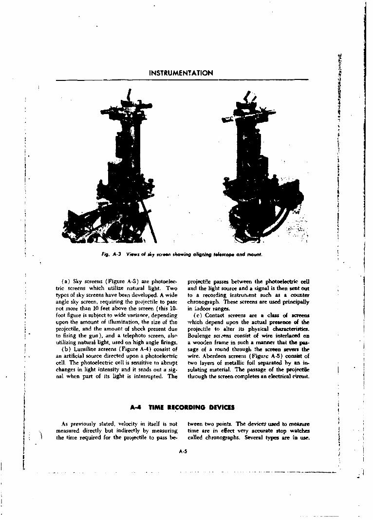
INSTRUMENTATION
Fig. A-3 Views of Aky screen showing aligning telescope and mount.
(a) Sky screens (Figure A-3) are photoe!ec. projectl'e passes between the photoelectric celtric screens which utilize natural light. Two and the light source and a signal is then sent outtypes of sky screens have been developed. A wide to a recording instrumaent such as a counterangle sky screen, requiring the piojectile to past chronograph. These screens are used principally
Pot more than 10 feet above the screen (this 10- in indoor ranges.foot figure is subject to wide variance, depending Wc Contact screens are a class of screensupon the amount of illumination, the size of the which depend upon the actual presence of theprojectile, and the amount of shock present due projectile to alter its physical characteristics.to firing the gun), and a telephoto screen, also' Boulenge scirens consist of wire interlaced onutilizing natural light, used on high angle firings, a wooden frame in such a manner that the pas-
(b) Lurniline screens (Figure A-4) consist of sage of a round through 'he screen severs thean artificial source directed upon a photoelectric wire. Aberdeen screenas (Figurc A-5) consist ofcell. The photoelectric cell is sensitive to abrupt two layers of metallic foil separated by an in-changes in light intensity and it sends out a sig- sulating material. The passage of the projectilenal when part of its light is interrupted. The through the screen completes an electrical circut.
A-4 TIME RECORDING DEVIICES
As previously stated, velocity in itself is not tween two points. The devices used to measuremeasured directly but indirectly by measuring time are in effect very accurate stop watchesthe tinme required for the projectile to pass be- called chronographs. Several types are in use..
A-5
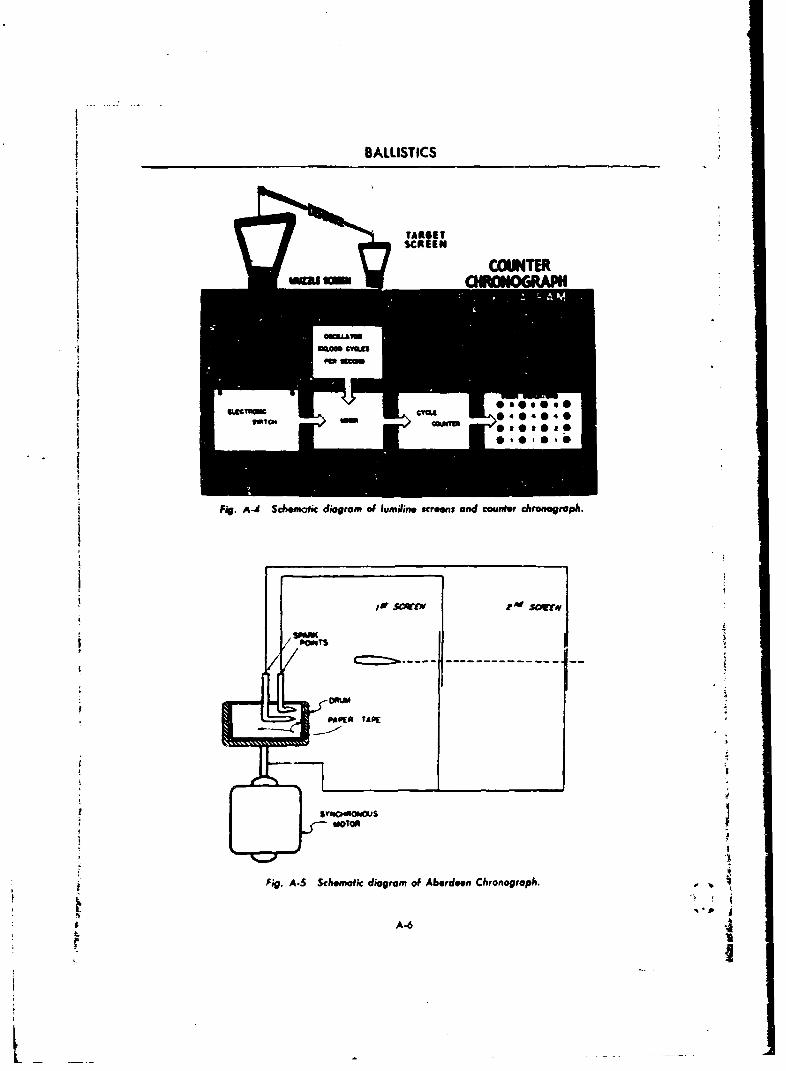
BALLISTICS
I •TARGET
.EIUCIp. CYU * 4 @404
Fig. A-4 Schdemnk- diagram of lumiline screens and counter chronograph.
SlPEfR TAPE
J. .
Fig. A-. Schematic diagram of Aberdeen Chronograph. -
SA-6
L
INSTRUMENTATION
A-4.1 AIERDIEN CHRONOGRAPH such as high velocity small arms firing, protec-This chronograph (Figure A-5) has been u tive circuits may nbt be sufficient to preclude the
chiefly for measuring velocities in small arms possibility of false operation. In such cases, antests. The present Mk. V Aberdeen Chronograph auxiliary chronograph should be used to check
the counter.is a portable instrument, housed in a bh x ap-proximately 11 by 15 inches. On the top of the The probablz error of the counter chronograph
box is mounted a shallow cylindrical drum with under favorable conditions is 2 X 10⁻⁵ seconds.its axis vertical, which is driven at a constant It is replacing the Aberdeen Chronograph.
speed by a small synchronous motor. A strip, of A-4.2 CAMIRA CHRONOGRAPH (SOLENOID)& treated paper is held in place on the inner cir- This instrument is a photographic oscillograph
cimference of the drum by cenhifugal force. providing a permanent record of the time ofThis strip is punctured by a spark when the pro- passage of the projectile through the screens orjectile passes through the screen. The time cor- coils. Photographed timing lines permit accurateresponding to any two spark points on the paper interpolation and the probable error can be miul-may be obtained by measuring the distanct be- tained as low as 0.00001 second.tween the points and substituting in the equa- Measuring velocities with the camera chrono-tion, t DD where t is the time in see- graph is necessarily slow, due to the time re-
15,000 quired to develop, fix, and dry the film before itonds and D is the distarce measured in milli- can be read. The average time for this processmeter, in the direction of rotation. is approximate:y twenty minutes. If several fir-
The advantages are the speed with which the ings are recorded on any one film, measurementi esults can be obtained, the simplicity of opera- of the first velocity may be delayed.tion of the instrument, and the ruggedness of the The outstanding advantages of the cameraequipment. The disadvantages are that the chronograph are that it may be used to obtainspark has a tendency to wander, i.e., does not velocitie., over long, noisy lines; that more thanalways jump in a straight line; its accuracy de- two coils or screens may be used to obtain form
Sperds upon the frequency of the power source; factors and drag functions; that a permanentSand the replacement of the screens must be record is obtained which can be rechecked if de-
handled with great care because of potential sired; and that the rate of fire can be determineddifferences of nearly 200 volts between the foil because of the ,ontinuously recorded operation.surfaces.
With three chronographs set up in parallel and A-4.3 MACHINI GUN CHRONOGRAPHwith proper adjustment of spark points, etc., the This instrument is essentia!ly an automaticprobable error of the system is about 4 < 10-5 counter chronograph which permits recordingSseconds. time intervals of automatic cannon and machine
The counter chronograph is the electrical gun fire. Readings are recorded on electrosensi-
equivalent of the mechanical stop watch. The tive papers, thus providing a permanent record.instrument consists of a series of counting ci'- The instrument operates in precisely the samecuits which are capable of recording time to manner as the counter chronograph except that1 X 10- •seconds. it can record the times, reset itself, and be ready
Protective circuits have been incorporated in for the next round at rates above 1800 roundsthe counter chronograph to protect against false per minute.operation when random interference is present In addition to recording velocities of eachon the signal lines. Unde-. certain conditions, round fired, the instrument records rate of fire.
r A-3 FIELD CHRONOGRAPH
This is a radar type based on the Doppler eA- and is picked up by a receiver after being re-feet. A wave of known frequency is transmitted flected from the moving projectile. TIe reflectedby means of a parabolic reflector behind the gun wave has a slightly lower frequency than the
S•A-7
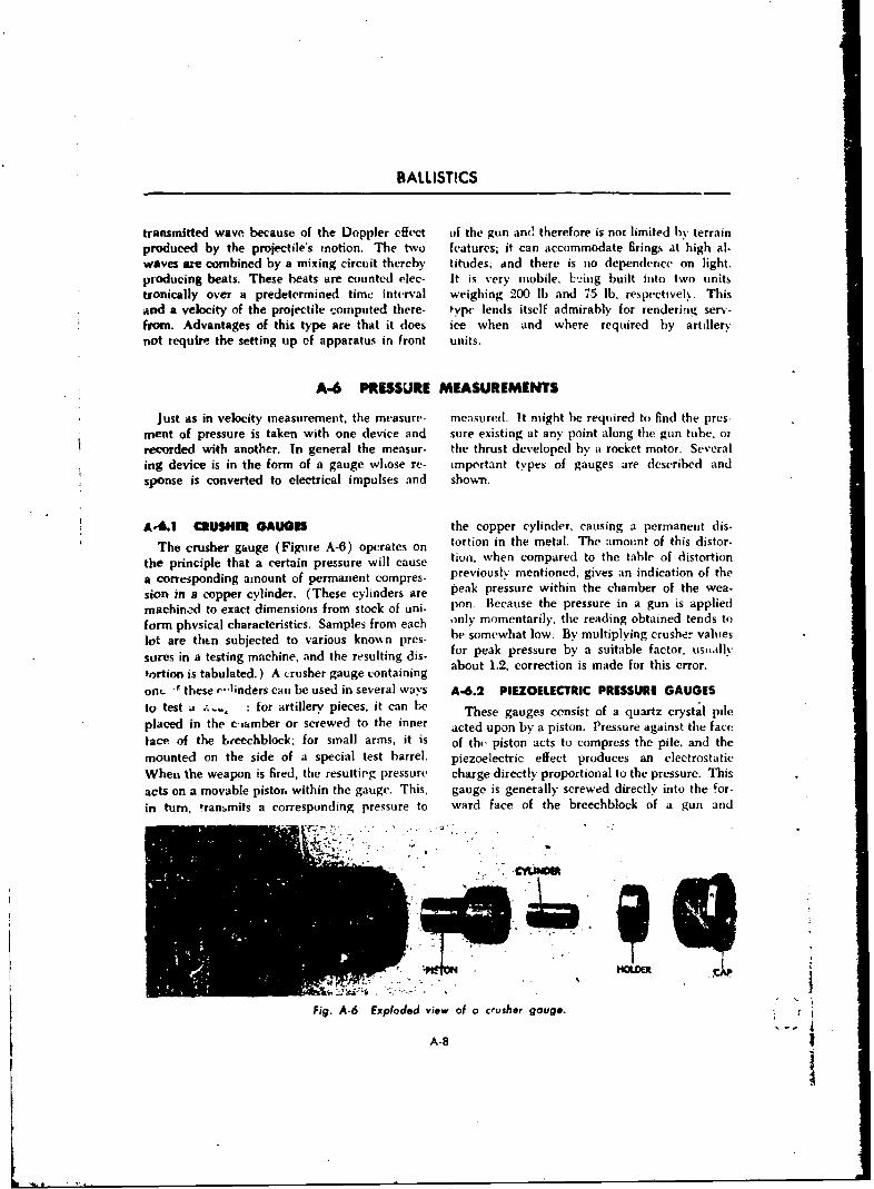
BALLISTICS
transmitted wave because of the Doppler cffect (if the gun an(' therefore is not limited by terrainproduced by the projectile's motion. The two features; it can accommodate firings at high al-waves are combined by a mixing circuit thereby titudes; and there is no dependence on light.producing beats. These beats are counted elec- It is very mobile, Lý,ing built into two unitstronically over a predetermined time interval weighing 200 lb and 75 lb, respectivel.. Thisand a velocity of the projectile computed there- type lends itself admirably for rendering serv-from. Advantages of this type are that it does ice when and where required by artillerynot require the setting up of apparatus in front units.
A-6 PRESSURE MEASUREMENTS
Just as in velocity measurement, the measure- measured. It might be required to find the pres-ment of pressure is taken with one device and sure existing at any point along the gun tube, orrecorded with another. In general the measur- the thrust developed by a rocket motor. Severaling device is in the form of a gauge whose re- important types of gauges are described andsponse is converted to electrical impulses and shown.
A-6.1 CRUSHER GAUGES the copper cylinder, causing a permanent dis-
The crusher gauge (Figure A-6) operates on tortion in the metal. The amount of this distor-
the principle that a certain pressure will cause tion, when compared to the table of distortion
a corresponding amount of permanent compres- previously mentioned, gives an indication of the
sion in a copper cylinder. (These cylinders are peak pressure within the chamber of the wea-
machin-d to exact dimensions from stock of uni- pon. Because the pressure in a gun is applied
form physical characteristics. Samples from each only momentarily, the reading obtained tends to
lot are thtn subjected to various known pres- be somewhat low. By multiplying crusher values
sires in a testing machine, and the resulting dis- for peak pressure by a suitable factor, usually
tortion is tabulated.) A crusher gauge containing about 1.2, correction is made for this error.
on,- -" these r-, linders can be used in several ways A-6.2 PIEZOELECTRIC PRESSURE GAUGESto test a -.. ,: for artillery, pieces, it can be These gauges consist of a quartz crystal pileplaced in the e imber or screwed to the inner acted upon by a piston. Pressure against the facelace of the beeechblock. for small arms, it is of the piston acts to compress the pile, and themounted on the side of a special test barrel. piezoelectric effect produces an electrostaticWhen the weapon is fired, the resulting pressure charge directly proportional to the pressure. Thisacts on a movable piston within the gauge. This, gauge is generally screwed directly into the for-in turn, transmits a corresponding pressure to ward face of the breechblock of a gun and
Fig. A-6 Exploded view of a crusher gauge. . 1A-8 i
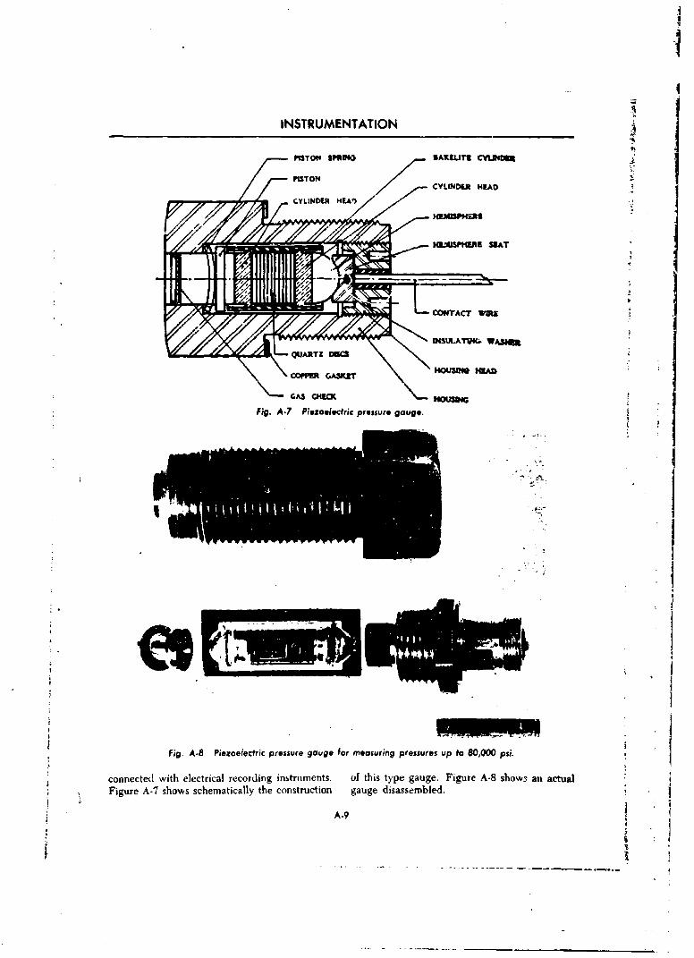
INSTRUMENTATION
PISTN SPINO AXPUT8 CflIWD
1MG"APHIRB MIAT
CONTAC WWD
koSLAM G S
Fig. A-7 Piezoeectdric pressure gouge.
Fig. A-8 Piezoelectric pressure gauge for measuring pressur es up to 80,000 Pai.
connected. with electrical recording instrtiments. of this type gauge. Figure A-8 show3 an actual
Figure A-7 shows schematically the construction gauge disassembled..
A-9
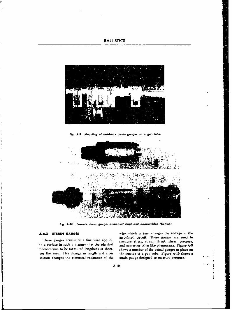
BALLISTICS
Fig. A-9 Mounting of resistance strain gauges on a gun tube.
M R511
7 . 4 -a
fig. A-10O Pressure strain gouge, assembled (top) and discssembled (bottom).
A-6.3 STRAIN GAUGES wire which in turn changes the voltage in the
Thes gages onsst f a ineWireappieý assouiated circuit. T7hese gauges are used toThee guge cosis ofa fne ireappie~ me,-.ure stress, strain, thrust, shear, pressure,
to a surface in such a manner that .he physical and numerous other like phenomena. Figure A-9phenomenon to be measured lengthens or short- shows a number of the actual gauges in place onens the wire. This change in length and cross the outside of a gun tube. Figure A-10 shows asection changes the electrical resistance of thc strain gauge designed to measuze presswue.
A-10
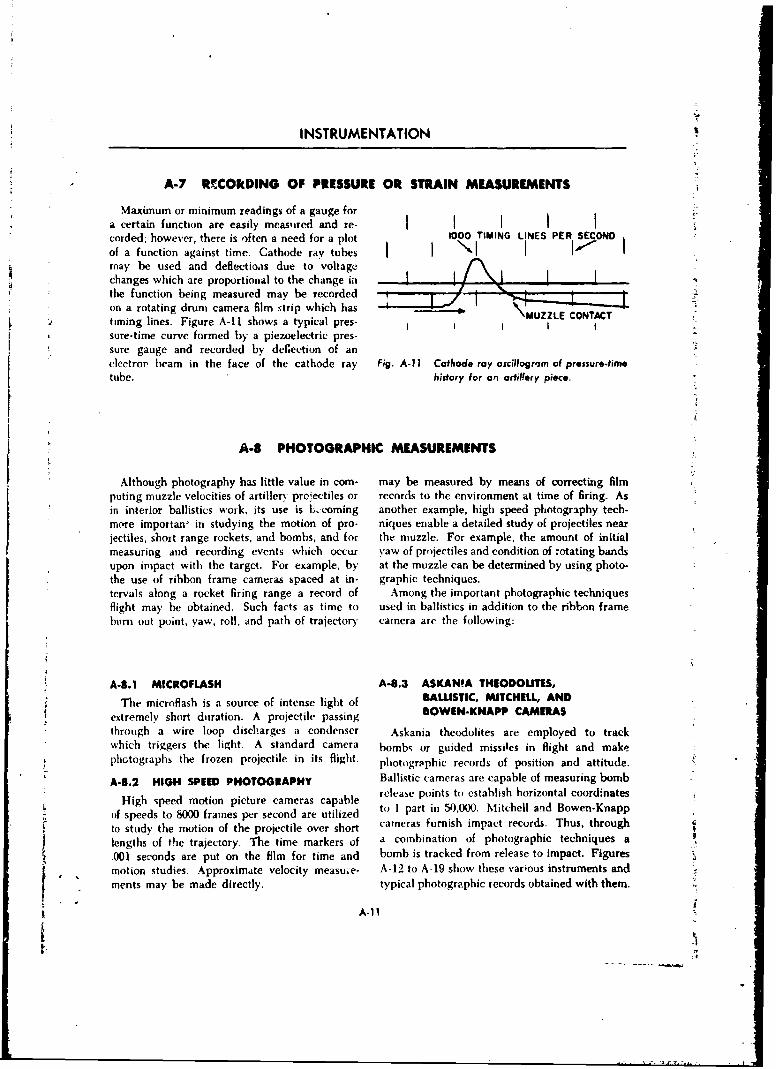
INSTRUMENTATION
A-7 RF.COkDING OF PRESSURE OR STRAIN MEASUREMENTS
Maximum or minimum readings of a gauge fora certain function are easily measured and re- I I I I Icorded; however, there is often a need for a plot 1000 TIMING LINES PER SECONDof a function against time. Cathode ray tubesmay be used and deflectioas due to voltagechanges which are proportional to the change inthe function being measured may be recorded --t-on a rotating drum camera film ',trip which has \MUZZLE CONTACTtiming lines. Figure A-1I shows a typical pres- I , I Isure-time curve formed by a piezoelectric pres-sure gauge and recorded by deCection of an Aelectro, beIam in the face of the cathode ray Fig. A-I1 Cathode ray oscilloomm of pressure.timetube. history for an artillery piece.
A-8 PHOTOGRAPHIC MEASUREMENTS
Although photography has little value in corn- may be measured by means of correcting filmputing muzzle velocities of artillery prejectiles or records to the environment at time of firing. Asin interior ballistics work, its use is Lecoming another example, high speed photography tech-more importan, in studying the motion of pro- niques enable a detailed study of projectiles nearjectiles, short range rockets, and bombs, and for the muzzle. For example, the amount of initialmeasuring and recording events which occur yaw of projectiles and condition of rotating bandsupon impact with the target. For example, by at the muzzle can be determined by using photo-the use of ribbon frame cameras spaced at in- graphic techniques.tervals along a rocket firing range a record of Among the important photographic techniquesflight may be obtained. Such facts as time to used in ballistics in addition to the ribbon frameburn out point, yaw, roll, and path of trajectory camera are the following:
A-8.1 MICROFLASH A-8.3 ASKAN!A THEODOUTES,
The microflash is a source of intense light of BALLISTIC MITCHELL, AND
extremely short duration. A projectile passing BOWEN-KNAPP CAMERAS
through a wire loop discharges a condenser Askania theodolites are employed to trackwhich triggers the light. A standard camera bombs or guided missiles in flight and makephotographs the frozen projectile in its flight, photographic records of position and attitude.
A-8.2 HIGH SPEED PHOTOGRAPHY Ballistic cameras are capable of measuring bomb,High speed motion picture cameras capable release points to establish horizontal coordinates
Hig Ipe motio picur cam0ras capablenBwe-Kapof speeds to 8000 frames per second are utilized o 1 part in 50,000. Mitchell and Bowen-Knapp
* to study the motion of the projectile over short cameras furnish impact records. Thus, through
lengths of the trajectory. The time markers of a combination of photographic techniques a
.001 seconds are put on the film for time and bomb is tracked from release to impact. FiguresS , motion studies. Approximate velocity measuxe- A-12 to A-19 show these various instruments andments may be made directly. typical photographic iccords obtained with them.
A-1 I
1!1
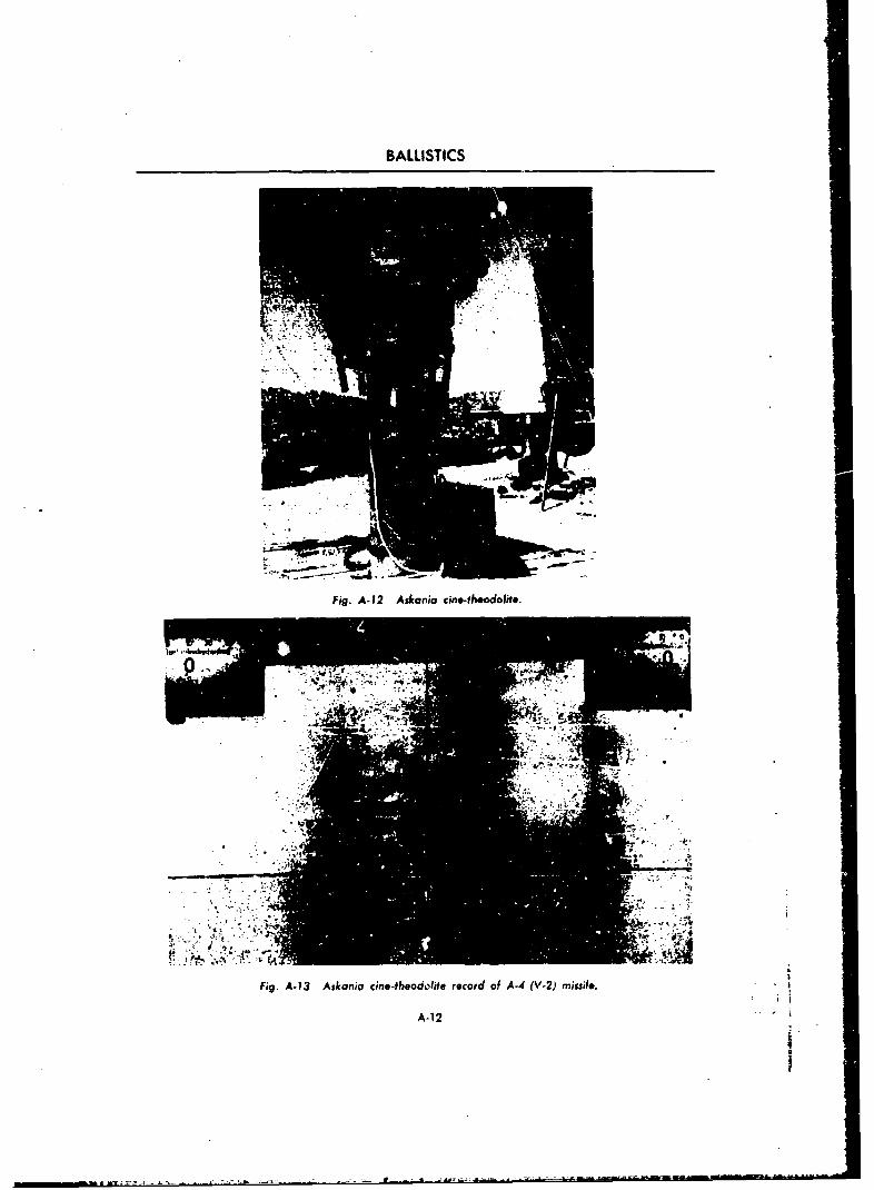
BALLISTICS
Fig. A-12 Askania cine-thoodolifo
Figý A-13 Askonia c6ne-theodoite record of A-4 (V-2) missile.
A-i12
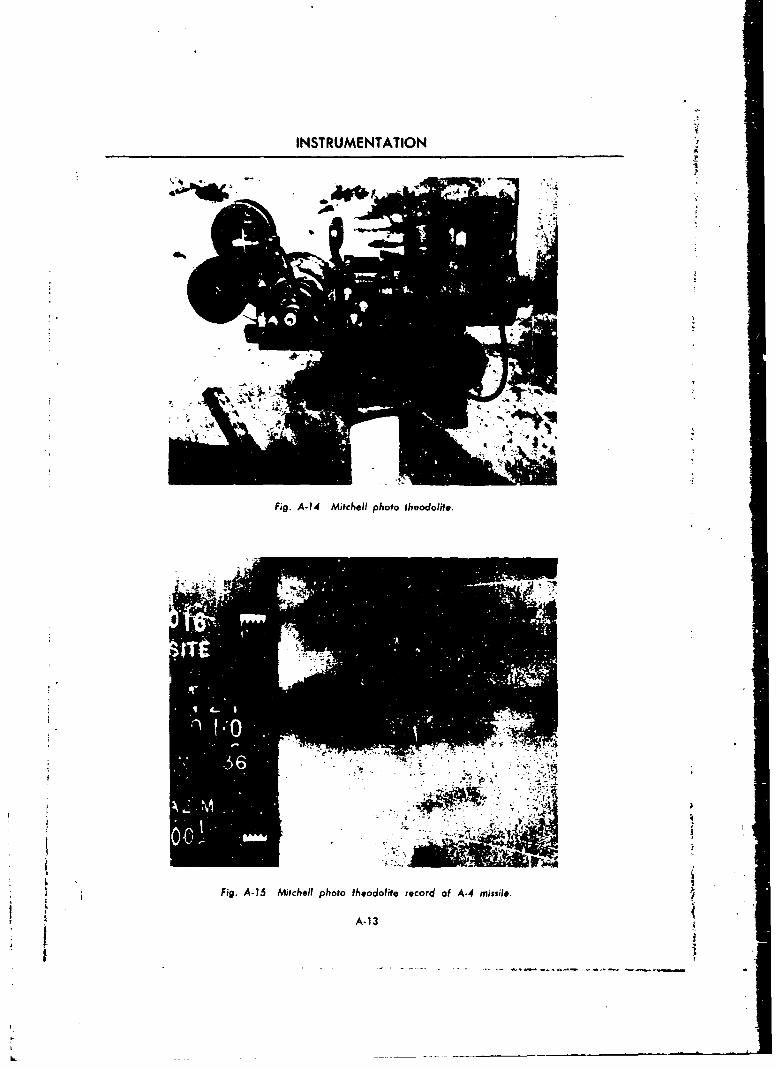
INSTRUMENTATION
i "
Fig. A-14 Mitchell photo theodolite.
Fig. A-15 Mitchell photo theodolite record of A-4 missile.
A-13i
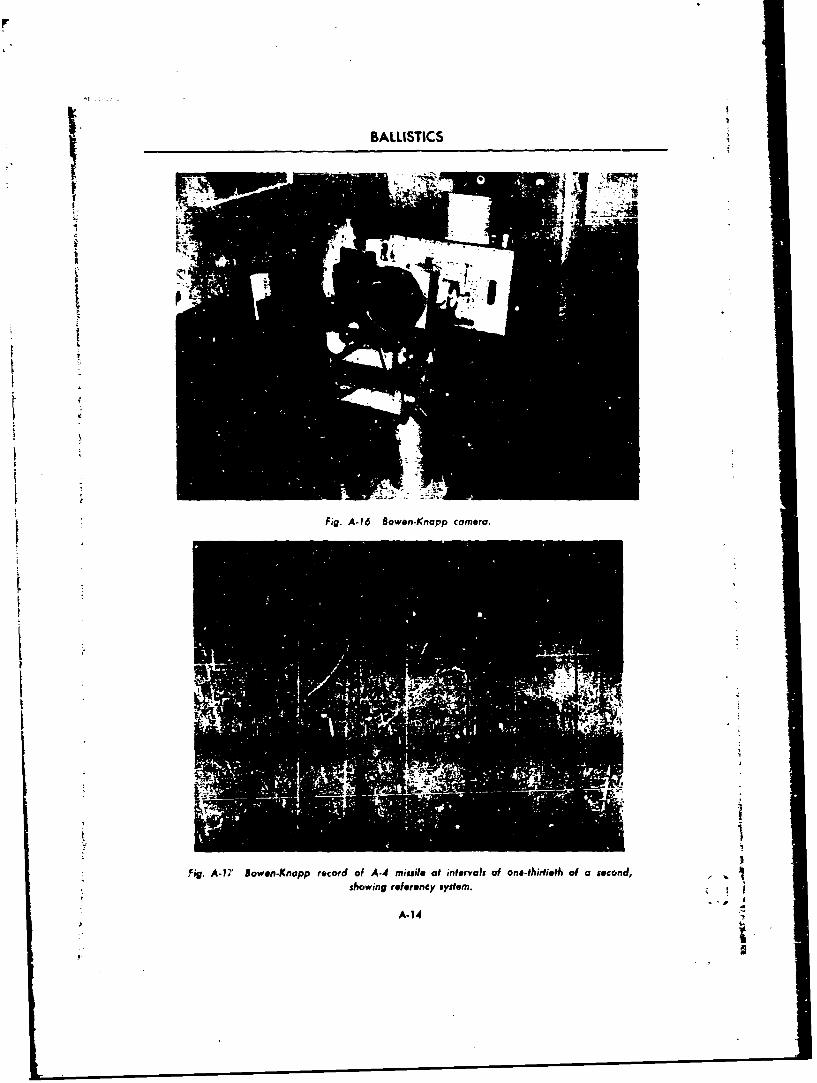
BALLISTICS
Fig A-16 Bowen.Knapp camera
fig. A-17 Iowen-Knopp reodof A-4 missile at intervalsofn&tiiehfascnd
showing ref ereney system.
A-1 4
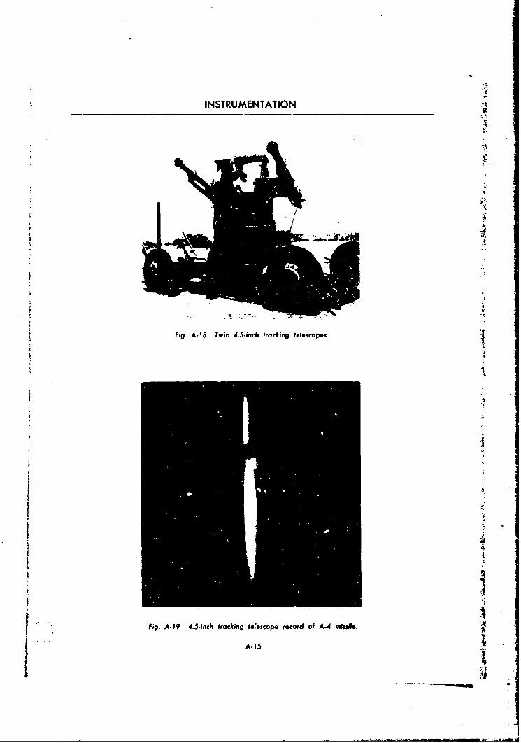
INSTRUMENTATION
A
€.
•. ......
L, Fig. A.- 8 Twin 4.5.inch frocking telescopes.
.4
S "' ~ Fig. A- 19 4.5.snch trackicng ieeBscope record of A.,4 missi/e. '
7 2
I . . ,
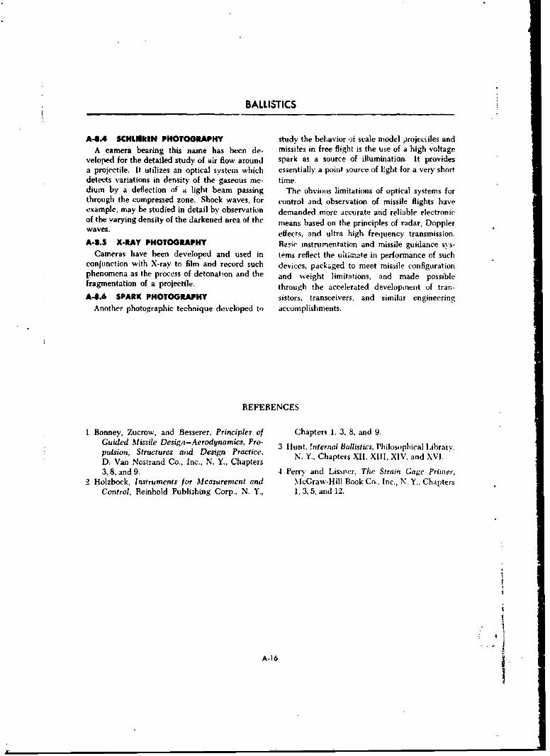
BALLISTICS
A4.4 SCHLIUkMN PHOTOGRAPHY study the behavior -a scale model projecifles andA camera bearing this name has been de- missi!es in free flight is the use of a high voltage
veloped for the detailed study of air flow around spark as a source of illumination. It providesa projectile. It utilizes an optical system which essentially a point source of light for a very shortdetects variations in density of the gaseous me- time.dium by a deflection of a light beam passing The obvious limitations of optical systems forthrough the compressed zone. Shock waves, for control and, observation of missile flights haveexample, may be studied in detail by observation demanded more accurate and reliable electronicof the varying density of the darkened area of the means based on the principles of radar, Dopplerwaves, effects, and ultra high frequency transmission.
A-8.5 X-RAY PHOTOGRAPHY Basic instrumentation and missile guidance sys-Cameras have been developed and used in tems reflect the uaiimate in performance of such
conjunction with X-ray to film and record such devices, packaged to meet missile configurationphenomena as the process of detonation and the and weight limitations, and made possiblefragmentation of a projectile. through the accelerated development of trar.-
A-8.6 SPARK PHOTOGRAPHY sistors, transceivers, and similar engineeringAnother photographic technique developed to accomplishments.
REFERENCES
I Bonney, Zucrow, and Besserer, Principles of Chapters 1, 3, 8, and 9.Guided Missile Desigt-Aerodynamics, Pro- 3 llunt, !nternal Ballistics, Philosophical Library.pulsion, Structures and Design Practice, N. Y., Chapters XII, XIII, XIV. and XVI.D. Van Nostrand Co., Inc., N. Y., Chapters3,8, and 9. 4 Perrn and Lissrer, The Strain Gage Primer,
2 Holzbock, Instruments for Mcasuremcnt and McGraw-Hill Book Co., Inc., N. Y., ChaptersControl, Reinhold Publishing Corp., N. Y., 1, 3,A5 and 12.
A-16

APPENDIX B 8
BALLISTIC ATTACK OF CONCRETE BY USING KINETICENERGY AND CHEMICAL ENERGY EFFECTS
B-1 INTRODUCTION
The close relationship of the response of rein- combat units are indoctrinated in procedures bestforced concrete to ballistic attack with that ex- suited to neutralizing such fortifications whenperienced by armor warrants the general conclu- andl if they appear. Likewise, terminal ballisti-sion that it shou!d be attacked with weapons cians must have weapons designed to supportproducing terminal effects similar to those best such an attack, or conversely, as in the case ofsuited for attack of armor. Tactically, history has design of armored vehicles, a suggestion as to theproved tl.e general ineffectiveness of elaborate factors which make defeat of such targets mostchains of concrete fortifications; however, all difficult.
B-2 DEFINITIONS
(a) Penetration, perforation. Same as for is a phenomena similar to spalling in armor inarmor. that it occurs on the rear face.)
(b) Massive penetration. Penetration where (e) Ricochet. The glancing off of the missilethere is no yielding of the material at the back from the front face of the concrete slab due toface. too high an angle of incidence.
(c) Spalling. The ejection of pieces of con- (f) Rebound. The bouncing back of the mis-sile from the front face of the slab. It generallycrete from the front face of the slab in the region occurs at low angles of incidence and at rela-
surrounding the point of impact. tively low striking velocities.(d) Scabbing. The ejection of pieces of con- (g) Sticking. The retention of the penetrating
crete from the rear face of the slab opposite the missile by the concrete at or near the point ofpoint of impact. (Note that scabbing in concrete maxinmum penetration.
it. B-3 BACKGROUND
At the beginning of World War II intelligence ably surprising to everyone to discover that al-r reports told of massive reinforced .-onerete fQrti- though extensive use of concrete had recentlyfications. in some case3 having walls seven feet been made in fortifications, notably in the[ -thick, built by the French and the Germans. Maginot Line and in the West Wall, no evidence
t Until that time research on concrete had been could be found in the available literature of anyundertaken in order to create a better basis for serious experimental work on the terminal ballis-the design of defensive structures. As World tics of concrete penetration. As a result, a seriousWar II progressed, and the emphasis shifted program was inaugurated to study the effectsfrom defense to offense, it was realized that basic that such factors as ricochet, deformation, rup-knowledge concerning the terminal ballistics of ture, and improper fuzing play on the efficiency
concrete penetration was needed. It was prob- of the attacking missile.
I ~B-1 I _tA
S --. - .2 n.lCfl<. 1 r
BALLISTICS
B-4 GENERAL EFFECTS OF INERT IMPACT
Spaling, caused by the impact of inert projec-tiles on concrete, causes craters on the front faceas shown in Figure B-I. The size of the craterformed increases rapidly with increasing strikingvelocities up to 1200 to 1500 ft/sec for ordinaryAP projectiles, but increases less rapidly at still PAT" or
___PROJECTILEhigher striking velocities. The crater shape is ra'isT SACKroughly conical, but extremely irregular. The caRt. ES, ,foA, sPCGRT P[ T Is PETALS
presence of reinforcing in a layer or mat nearthe front face tends to have a constricting effecton both the size and shape of the crater. FigureB-I also shows the difference in the general effect TWa CONCR•TE SLAS T,°4P ARMOR P.ATE
of inert impact on concrete and steel.For a given missile and target, the average Fig. B-I Comparison of inert impact against
noimal penetration may be expected to increase armor and concrete.with striking velocity according to a smoothcurve. When scabbing sets in, penetration be-gins to increase rapidly with striking velocity. on the back surface, followed by scabbing of in-The effect of repeated hits on reinforced concrete creasing extent. The back scab crater is usuallydepends on the dispersion of the points of impact wider and shallower than the front spall crater,and the degree to which slab reinforcement tends although both tend to be very irregular. Belowto hold the debris in place to offer resistance to the scab limit a concrete wall will offer adequatelater shots. Small dispersion, such that successive protection to personnel or equipment not in di-hits fall within the spall crate- of the first shot, rect contact with the slab and therefore notis advantageous for the attack if the object is to directly subjected to whatever mechanical shockSperforate the slab as soon as possible with at may be transmitted through it. However, as soon
* least one projectile. as scabbing occurs, pieces of considerable sizeRicochet increases sharply with obliquity. and velocity may be thrown off as fragments.
Ricochet greatly handicaps the missile with re- Thus scabbing is the first serious source of dangerspect to the target thus enhancing the protection to the objects which the slab is designed to pro-afforded by the slab. This applies particularly to tect. In this light the scab limit rather than theexplosive projectiles or bombs in cases where the perforation limit is often used as the principaliuze delay time permits the detonation to occur criterion in the design of protective concrete.with the missile no longer in contact with the The edge effect. If a projectile or bomb strikestarget. The lateral and turning forces acting on near an edge of a concrete slab, it tends to bethe missile during ricochet also pose difficult deflected toward the edge, thus tending to breakproblems for the fuze designer. Although per- out concrete toward the edge. The effect de-foration and ricochet cannot, by definition, occur pends not only on the striking obliquity and the
simultaneously, it is possible to have a scab nearness to the edge, but also on the design of
thrown off the back face of the slab when the the reinforcing used near the edge. Firing testsshow that the edge effect will occur farther fromm issile ricochets. W ith su ffi ciently th in sla hs th ed e a s ri ng v l c y i c e s s. W k rthe edge as striking velocity increases. Weaker
the front and back craters so formed have been concrete permits deeper penetrations and greaterobserved to join leaving a clear hole through edge effects. Due to the edge effect, embrasures.the concrete, even though the piojectile remains firing ports, and doors are the weakest parts ofon the attacking side and does not perforate in a structure. They are the natural points of attackthe true sense. and therefore merit particular attention in the
For a given concrete target a progressive in- design of fortifications aid other defensive struc-crease in striking velocity first produces cracking tures.
B-2 "
BALLISTIC ATTACK OF CONCRETE
B-3 GENERAL EFFECTS OF HIGH EXPLOSIVE IMPACT
The previous sections have dealt principally penetration. If the target is too thick to be per-with the effects of inert impact on a reinforced forated, such missiles will rebound instead ofcorcrete structure. With explosive bombs and sticking.projectiles the effect of the explosion is super- Effect of an explosion in massive penetration.
'uimposed on the inert effects prevailing at the The effect of an explosion following inert pene-minstant of detonation. The effect of the explosion tration into a massive concrete target is illustratedon the target is conditioned by the position in Figure B.2, It is evident that the increase inwhich the missile has reached at the time of penetration depth is fairly small. According to adetonation, and also by the deformation, if any, rough rule of thumb this increase in depth ofwhich the missile may have suffered in the hole is only about X1 caliber or less for commonprocess. If a missile remains intact during perfo- types of H.E. missiles. In this example theration, and detonates after clearing the back fa", charge made up 201 of the weight of the missile.it will cause the maximum damage of which it The profiles in Figure B-2 show that the lateralis capable. effect of the explosion is relatively larger than
Experience indicates that a projectile must the increase in depth of the penetration hole duepenetrate to a depth of 3.5 to 4.5 calibers before to explosive effect. The removal of concrete spallit will stick. The phenomenon of sticking is of and the widening of the front crater are particu-special importance with explosive missiles. The larly important with repeated fire.maximum effect of detonation is secured whent'.e explosion takes place at the deepest pene- LEGENDtration that can be attained. It is almost im- EIpossible to fuze accurately for this condition if Wumm SLAI LIPLOSIthe projectile rebounds. In general. the fuze 1FPET WPPESTdelay should allow time for perforation or themaximum penetration before the missile deto-nates. If the fuze delay is longer than the timerequired for either perforation or maximumpenetration, the maximum damage will be at-tained except in the case of rebounds. If the fuzedelay is shorter, the missile will be definitelyhandicapped in almost all cases. The mass andstriking velocity of some artillery shells and ofmost bombs are usually too low for sticking Fig. 8-2 Effect of explosion in concrete.
B-6 SOLUTION TO THE PROBLEM OF PERFORATION OFTHICK REINFORCED CONCRETE
During World War 1I, a considerable amount A.T. projectiles, of which 105-mm was our largestof development work was done on both sides artillery caliber; on the other hand, excellent re-toward increasing the effectiveness of explosive sults were demonstrated with available monoblocmissiles against concrete. The Germans de- AP shot as far as penetration and perforationveloped special anti-concrete projectiles for artil- alone were concerned. However, this type plery fire (150-mm, 210-mm, etc.) as well as anumber of shaped charge projectiles and bombs duced relatively poor destructive effect alterwhich could be used against concrete as well as perforation.armor. Experience in this counitry showed in- It was determined that a high capacity H.E.sufficient concrete penetration ability in our H.E., shell was needed which would remain essentially
5-3
---------
BALLISTICS
Fig. 3.4 105-mm H.E. fuzed superquick testblock 3 feet thick showing relative in*ffctiven*ss
cf 105-mm H.. shell, fuzed juperquick,
Fig. 9-3 Concrete piercing fuze. against concrete.
intact during the inert -a-ac: stage pre- The development of a concrete piercing pointceding detonation. This promotes maximum in-- detonating fuze to fit the complete ordnance lineert penetration and keeps the charge and fuze in of standard H.E. shells was ýben initiated. Thecondition for high order detonation; at the same final production type, with a sharp contour fortime, of course, the fuze must provide sufecient better blending with ogives of most H.E. shells,delay time to permit maximum penetration (or, was identified as the fuze, C.P., M78, within the best case, perforation) before the charge booster M25. As standardized, it is made ofis detonated. It was found by firhig trials that WD 4140 chrome-molybdenum steel, wvith athe standard H.E. artillery shell, in all calibers, Ruckwell C hardness of 30 to 40 (BHN 288-377).was strong enough to resist deformation during Figure B-3 is a cutaway view of the fuze.penetration provided that a hard nondeforming Figure B4 shows the damage (or more cor-steel fuze body could be made to replace th2 rectly the lack of damage) caused by impact andstandard point detonating fuze in the nose of theshell, with sufficient delay time to permit maxi- functioning of 105-mm H.(. shell fuzed suoer-mum penetration or perforation. This, coupled quick. Figure B-5 (a) and (b) show by way ofwith the discovery that the TNT charge would contrast the damage caused by impact and func-
not detonate spontaneously on impact, led to a tioning of 105-mm H.E. shell with concretedecision to approach the concrete perforation piercing fuze when fired against a steel rein-problem by investigating fuze designs. forced concrete test block three feet thick.
1-7 PROBLEMS OF EMPLOYMENT
Because the NI-78 fuze differed in contour C.P. and the M-48 P.D. fuzes showed that theand weight from the standard P.D. fuze it was difference in ballistic coefficient between thefound not to be ballistically interchangeable with fuzes could be applied as an air density correc-it. However, comparative firicgs of the M-78 tion; hence firing tables for M-48 fuzed shell are
B-A
BALLISTIC ATTACK OF CONCRETE
ji
Fig. 8-5 (a) Effect of 105-mm HI. shell with concrete piercing fuze
(front view).
Fig. 8-5 (b) Effect of 105.irin H.E. shell with :onccete piercing fuze(rear view).
applicable until more accuirate tables for the t hit on the concrete target. Upon missing theC.P. fuze are available, target the .025 second delay ime of the fuze
permitted the shell to penetrate earth and toIn actual employment, M-78 fuicd shells were function with little flash or smoke. This disad-
found to be difficult to sense when they failed vantage wa:; overcome by removing the delay
B
-. -- -
I a. . -S~r -- m
BALLISTICS
n- FPTI, OF PaNIThATI TOKae4a
- -X/_e 9._ -. 0.- -)
a I L
IqeSe"eaaII. -___ - ---- "-* -
Fau gd. B-6m Efeto sae hrg gi oceen es e 0 nme te ue
Non-Delay. Each box containing twenty M-78 fuzes should be used first, ontil hits are obtainedfuzes contains four of the non-delay ty-pe, which on the concrete target.
B-8 EFFECT OF THE SHAPED CHARGE AGAINST CONCRET/E
The effect of the shaped charge against con- tion depth which results in massive concrete.crete is shown in Figure of-6. Depth of penetra- A weak thick wall will resist penetration bet-tion produce( resulted from charges with axes ter tipan a thin strong wall, since there is cotp -perpendicular to the slab f~ic n Shaded band in- paratively little differsnti it are ote densityfudes calues 2 above and bolof the mean between the two and penetration appears to bevaThe. fectaus, of scabptedg •n the rear face (see dependent on densiec. Additional protection is
inset sketches) perforation often results even iafforded concrete against shaped charge attackwhen slab thickness is greater than the penetra- by the addition of steel plates front and back.
REFEFENCES
No genera;, unclassified references are available.

INDEX
Accelerometer, 5-7 water bursts, 9-3
Aerodynamic forces 3-4(see Forces, aerodynamic) Ballistic attack of concrete, B.1
Aerodynamic missiles, 4-1 Ballistic cameras, A-11configuration, 4-12
plan forms, 4-15 Ballistic coefficient, 3-8profiles, 4-15 for bombs, -- 11
steering, 4-16 Ballistic missiles, 4-1trajectories, 4-1 esterior ballistics, 4-7
Air blast loading, 8-9 flight, 4-6
A-Jr effects, 1-17 systems, 4-3
Airfoils, 4-15 Ballistic tables, 3-2, 3-9
forces on, 4-16 Ballistic trajectories, 4-1lift and drag coefficients, 4-17 theory of, 4-9nomenclature, 4-16 Ballistics, armor, 10-6
Air-to-surface missile, 5-9 penetration resistance, 10-7Armor, 10-1 shock resistance, 10-7
ballistic attack, 10-1 spall resistance, 10-7
ballistic propertik,. I-6 Ballistics, exterior, 3-1, 4-7obliquity, 10-7 Ballistics, fragments, 7-1penetration, 10-18 (see also Fragments)petalling, 10-8plugging, 10-9 Ballistics, interior, 1-1resistivity, 10-22 Ballistics, terminal, 6-1shatter, 10-19
fabrication, 10-4 Ballistics, transition, 1-16penetration, 10-18 inWtial air effects, 1-17
elastic response, 10-19 lateral jump, 1-19plastic response, 10-19 vertical jump, 1-18
surface design, 10-4(see also Design of armor) Bipropellants
types, 10-1 (see Liquid propellants)
body, 10-31 Black body radiation, 9-5cast steel, 10.1face-hardened steel, 10-3 Blast effects radii, 8-13
nonferrous, 10-4 Blast impulse, 8-7rolled steel, 10-1 Blast pressure, 8-4
Artillery trajectory, 3-4 Blast wave, 8-1
Atomic detonations, 9-1 technical aspects, 8-10blast effects, 8-12 Body carmor, 10-31
cratering, 8-13equipment, 8-12 Bombing problems. 3-14genetic, 9-16 altitude corrections, 8-12personnel, 8-12 burst height, 7-10structures, 8-13 crater data, 8-14
injuries from, 9-6 cross trail, 3-15surface burst, 9-2 linear travel, 3-15underground burst, 9-2 low altitude, 3-16
F-i

Bombing problems (conw) Diffraction loading, 8-9
stabilization Discarding sabot projectiles, 10-23(see Stabilization) Distribution of ..ergy, 1-3
trail, 3-15vertical travel, 3-15 Doppler effect, A-7
Bombing tables, 3-13 Drag coefficient, 3-7
Bombing techniques, 3-15 Drag loading, 8-10
Bowen-Knapp cameras, A-11 Drift stabilized projectiles, 3-19
Brayton cycle, 2-26
Bremsstrablung, 9-16 Earth satellites, 4-10
Bursting shell, 6-2 Edge effect, B-2
Energy distribution, 1-3
Capped projectiles, J.0-20 Engines, jet
Celestial navigation, 5-7 (see Jet engines)
Cesium, 9-15 Erosion, 1-13effects, 1-17
Charge efficiency, 1-8 gas, 1-14
Chemical energy projectiles, 10-24 Exhaust velocity, 2-11
Chronographs, A-5 Explosive charge detonation, 10-28Aberdeen, A-7camera, A-7 Exterior ballistics, 3-1, 4-7field, A-7machine gun, A-7 Falout, 9-13
Coefficient, ballistic, 3-8drag, 3-7 Firing tables, 1.13
Command guidance, 5-8 calculations, 3-11
Composite rigid projectiles, 10-22 Fission fragments, 9-9
Composition B, 74 Force, aerodynamic, 3-4Coriolis, 3-10, 5 8
Coriolis force, 3-10, 5-8 crosswind fo.-ce, 3-5
Courses, intercept drag, 3-5(see Intercept courses) magnus force, 3-6
Crusher gauge, A-8 magnus momept, 3-6overturning moment, 3-6rolling moment, 3-6
Damage distribution, 6-8 yawing moment, 3-6function, (-9pattern, 7-9 Foxholes, 7-7
Data analysis, - Fragmenttion, 7-1
Design of armor, 10-4 comparative, 7-8
composite, 10-6 controlled, 7-12
innovations in, 10-5 Fragments, ballistics of, 7-1laminated armor, 10-0 damage, 7-7spaced armor, 10-6 dispersal, 7-5
Detonation, 20-mm shell, 7-2 initial velocity, 7-4bomb, 7-5 quantitative data, 7-5grooved ring shell, 7-16 recovery of, 7-6
!-,

Fuel, rocket, 2-12 gun chamber, 1-11burning, 2-13 gun tube length, 1-11combustion limit, 2-14 projectile weight, 1-11
pressure limit, 2-15 sectional density, 1-11
storage, 2-15temperature sensitivity, 2-13 Hand grenade, 7-17
Fuzed shells, B-5 Heat engine, 4-12
Fuzing, ballistic missile. 4-4 High explosives, 8-5
High explosive impact, B-3Gamma radiation, 9-9 High explosive projectiles, 10-31Gas erosion, 1-14
High speed photography, A-i1Gauges, crusher, A-8
piezoelectric, A-8 Hist-,grams. 6-5
strain, A-10 Homing guidance, 5-11
Grain characteristics, 1-5 Hyperbolic grid, 5-6
configuration, 1-6loading density, 1-7size, 1-6 ICBM, 4-
Gravitational force, 4-11 Ignition, 1-4direct conduction, 1-5
Guidance, 5-1 radiation, 1-5
attitude control, 5-1changing trajectory, 5-3 Impact, high explosive, B-3
path control, 5-2 inert, B-2
terminal, 5-10 projectile, 10-14
trajectory, 5-3 Impulse, specific, 2-.l
Guidance systems, 5-1 Inertial guidance, 5-8active homing, 5-11beam rider, 5-9 Inert impact, B-2
celestial navigation, 5-6 Instrumentation, A-1
command, 5-8dual-beam rider, 5-10 Intercept courses, 5-13homing, 5-10 constant bearing, 5-15inertial, 5-7 deviated pursuit, 5-15intercept problem, 5-14 line of sight, 5-15
kinematics of. 5-13 proportional, 5-16
passive homing, 5-1'2 pure pursuit, 5-15
preset, 5-3 Interior ballistics, 1-1, 2-1
radio navigation, 5-4 (see also Jet engines)semi-active homing, 5-12 control of, 1-4single-beam rider, 5-10terrestrial reference. 5-4 lonizatioi, 9-10
Gun action, 1-2 IRBM, 4-1
Gun efficiency, 1-8 jectiles, 10-2
Gun systems. 1-10causes of wear, 1-12 jet engines, 2-20
gun bore erosion, 1-13 principles, 2-1
gun temperature, 1-13 pulse jets, 2-21
powder temperature, 1-13 ram jets, 2-22
density of loading, 1-11 (see also Ram jets)
1-3

jet engines (cont) Momentum thrust equation, 2-2
specific impulse, 2-3 Muzzle pressure, 1-4tIust, 2-24 Muzzle velocity, 1-15
Kinematics, 5-13 Neutron particles, 9-9induced activity, 9-12
Kinetic energy projectiles, 10-11 sources, 9-10Newtonian constant, 4-9
Lateral jump, 1-18
IALDuc equations (projectile velocity), 1-9 Nike missile, 5-9
Limiting velocity. 3-14 Nozzles, 2-5angle correction factor, 2-9
Liquid fuel feed system, 2-16 configuration, 2-9convergent-divergent, 2-2
Liquid propellant rockets, 2-15 design, 2-5chamber pressure, 2-16 distance along, 2-7motors, 2-17 entrance and exit angles, 2-9pressure feed :ystem, 2-17 pressure distribution along, 2-8pump feed system, 2-18 schematic flow diagram, 2-4
Liquid propellants, 2-18 Nuclear radiation, 9-8requirements, 2-19 effects of, 9-11utilization, 2-19 fallout, 9-13
Liquid rocket feed system, 2-18 long-term hazard, 9-15neutron induced, 9-12
Mach number, 3-6 residual, 9-12
reflection, 8-5 sources of, 9-10
region, 8-9wave, 8-6 Ogive, 3-6
Measarement, pressure, A-8 Orbits, satellite, 4-10velocity, A-4 Oscillogram, A-11
Missile, IRBM, 4-1 Overpressure of shock wave, 8-3Nike, 5-9Redstone, 4-4 Overspun projectiles, 3-18V-2, 4-5 Overturning moment, 3-7
Missiles, aerodynamic(see Aerodynamic missiles) Peak pressure of shock wave, 8-3
Missiles, ballistic Perforation of concrete, B-3(see Ballistic missiles]
Photographic measurements, A-i1Missiles, configuration, 4-12 high speed photography, A-11
aerodynamic steering, 4-16 Schlieren phc.)gr~phy, A-16airfoils, 4-16 spark photography. A-16
plan forms, 4-15 X-ray photography. A-16profile shapes, 4-15
Mitchell camera, A-I1 Piezoelectric gauges, A-8 4.Pitch axis, 5-1, 5-2
Moment, magnus, 3-6overturning. 3-6 Powder grain effects, 1-5rolling, 3-6 density of loading, 1-7 -
yawing, 3-6 grain configuration, 1-6
1-4

Powder grain effects (conw) utilization of, 219solid, 2-13
grain size, 1-6 changes in storage, 2-15
Precession, 3-18 combustion limit, 2-14mode of burning, 2-13
Pressure calculations, 1-12 pressure limit, 2-15
Pressure measurements, A-8 temperatures, 2-13
recording of, A-11 utilization system, 2-21
Pressure-time relationships, 1-7 Pulse jet, 2-22for 3.25-inch rocket, 2-5 characteristics, 2-26
Pressure-travel curves, 1-3
Pressure-travel relation, 1-6 Radar, 5-9
Probability, 64 Radiation, nuclear
damage distribution, 6-8 (see Nuclear radiation)
damage function, 0-9 Radiation, "hermal
of successful mission, 6-8 (see Thermal radiation)
product rule, 6-8 Radioactive decay, 9-14
sum rule, 6-4 (see also Fallout)
Product rule, 6-8 Radio na'igation paths, 5-5
Projec~iles, 10-21 Ram jets, 2-22form 3-7, -2form, 3-7 characteristics, 2-26
impact osubsonic ram jets, 2-22limiting velocity, 3-14 supersonic ram jets, 2-23penetration, 10-25"performance, 10-23 Reaction motors, 2-20, 2-27
capjped projectiles, 10-20 characteristics, 2-28
composite rigid, 10-22 principles, 2-1discarding sabot, 10-23jacketed projectiles, 10-22tapered bore projectiles, 10-23 Recoilless gun system, 1-2
stability factor, 3-18 Redstone 'missile, 44terminal velocity, 3-15types, 10-19 Reynold's number, 3-6, 4-17
capped, 10-20cappd, 1-9-0Ricochet, B-I
chemical energy, 10-24 Rcomposite rigid, 10-22 Rocket fuel, 2-26discarding sabot, 10-23 (see also Fuel, rocket)
drift stabilized, 3-19 Rocket fuel consumption, 2-28
jacketed, 10-22kineric energy, 10-11 Rocket motors, ?A
overspun, 3-18 characteristics, 2-28
shaped charge impulse-weight ratio, 2-5
(see Shaped charge projectiles) thermodynamics, 2-4
spin stabilized, 3-19 thrust, 4-10
tapcied bore, 10-23 thrust coeffcient, 2-5
underspun. 3-18 Rockets, liquid propellant, 2-15
Projectile velocity computation, 1-9 pressure feed systems, 2-17
Propellants. combustion limit, 2-16 pump feed system, 2-18
energy of, 1-3 Rockets, solid propellant, 2-11
liquid, 2-18 characteristics, 2-13
selection of, 2-18 grainl geometry, 2-12
i b.S--
R 'Y

Rocket staging, 4-11 Supersonic airfoils, 4-15
Roll axis, 5-1, 5-2 Supersonic ram jet, 2-24
Surface-to-surfacf missile, 5-9Satellites, 4-10 System errors, 6-9Scabbing, B-1
Schlieren photography, 3-2, A-16 Tapered bore projectiles, 10-23
Shaped charge projectiles, 10-24 Target analysis, 6-3angle of impact, 10-29angle of liner, 10-28 Targets, 6-12confinement of charge, 10-28 area considerations, 6-13design and manufacture, 10- extension chart, 6-12detonation of charge, 10-28 point chart, 6-11effect against concrete, 6 ci.tular, 6-15functioning. 10-25 ircular, 6-15liner dimensions, 10-28 irregular, 6-15liner shapes, 10-29 point, (,-0penetrArion, 10-28 Telemetry, A-2performance, 10-30rotation, 10-29 Temperature effects, 1-13Aize of charge, 10-28 Terminal ballistics, 6-1standoff distance, 10-29 area target considerations, 8-13
Shatter, 10-19 circular targets, 6-15damrnge function, 6-9
Shock to annor, 10-7 irregular targets, 6-15
Shock tube. 6-3 statistical methods, 6-4system errors, 6-9
Shock velocity, 8-11 target ana!ysis. 6-3
Shock wa'-e overpressure, 8-3 Terminal guidance, 5-10
Solid propellant rockets Terminal velocity, 3-15(see Rockets, solid propellant) Theodolites, A-li
Spalling, 10-7 Thermal radiation, 9-3Spark photography, A-16 absorption, 9-5
Specific imp'ilse, 2-3 attenuation, 9-4damage radii, 9-8
Spin stabilized projectiles, 3-19 dose effects, 9-11
Stabilization, 3-16 emission, 9-4fin, 3-16 injuries. 9-6roll, 3-17 mechanism, 9-3spin, 3-17 second radiation pulse, 9-6
stability and drift, :3-19 temperature pulses, 9-4
Staging, rocket, 4-11 Thiokol, 2-11
Statistics, 6-5 Thrust, 2-2momentum, 2-2
Strain gauges, A-10 totaj, 2-3
Striking angle. 10-15 Thrust cut-off, 4-7
Strontium, 9-15 Time-pressure relations, 2-14
Subsonic ram jet. 2-23 Time recording devices. A-5 -"
Sum ru!e, 6-4 Aberdeen chronograph, A-7
1-6
//

Time recording devices (cont) V-1 missile, 2-21
camera chronograph, A-7 V-2 missile, 4-5field chronograph, A-7machine gun chronograph, A-7 Velocity, exhaust, 2-11
fragment, 7-4, 7-12TNT, 7-4, 8-5 muzzle, 1-15
projectile, 1-9Total thrust equation, 2-3 terminil, 3-15Trajectories, 3-3 Velocity computations, 1-9
aerodynamic, 4-1analysis, 3-10 Velocity measurements, A-4artillery, 3-4
ballistic Volocity. exhaaP, 2-11
(see alo Ballistic trajectories) Vertkd" juit 1 i18fixed coordinate, 4-8guidance, 5-3, 5-8hypervelocity vehi!le, 4-3 Wi± omb are. rule 1-1ICBM, 4-6 \• ,nd tunnel, fLextit- throat, 3-1medium height, 4-7 Sd frrm photo. --2physical effects upon, 4-7plots of, 3-9 Wind tmmui tests, Langley Aer,,nautical
short range, 4-8 Labomatry, 4-'3TNaffett Fielh. California, 4-14Transition Ballistics
(see Ballistics, transition) X-ray photography, A-16Turbo jet characteristics, 2-26
engine cycle, 2-26turbine, 2-25 Yaw angle, 3-k
axis, 5-1, 5-2plane, 3-5
Underspun projectiles, .3-18 response, 3-20
1-7
* u s OV(*SMI!ItF'IU IftUrlG O~ICB 1(MS o-.I.*)*

it
A
ENGINEERING DESIGN HANDBOOK SERIESTht EngineerLng D-ssin Hai.ibou Serics is iiendec to provide a compilation of princtples and fundamental data to
Supplrn~rn~t rp iietoAc sitting -iginer cm thti evolu ion of ni w designs whuch will meet tac-scal -Ad techitical
needs wthile also embodying satisfactory pruducibiltt, and maintainability.
Listed below are thr Hand.uo.kaxhich have be'er pubhihadnr aOobiriittrd farpublication. HAndbooks wntb publication
dates prier to I August lr,lr er, published as 20-series Oronance Corps paniphlets. AMC Circular 310-3, 19 JitlyI Y-be, redestRntated thuse psblhcattnis as 70n-ser-ie AMC parnphlets hie., e D.-P Zu- 138 w-as redesignated AMCP 706.1 38). All new, ri irirntd, or rcvtocd hiandbooks -re being published as 70t-sertes AMC pitniphlets,.
General and ML. ll...neois Subjects Bllistic Missile Serie• Sc
Number littC Number Title106 Eleiectts of Armamtent .igintecring, Part f'li, r B I(S- RD) Wa.Apon System lfecti.'ctess (U)
Suurces of Energy Lbz Pr.,pulsiun and Prop-llaits107 Elentetis of Armament Engitneering, Pant Two, 284(C) Trajectories (U)
Bali]stics a18( Structures108 Elements of Armament Engitieering. Part Three,
Weapon Systems and Components flallistice Series
110 Expericuen-al Statistics. Section 1, Pastc Cons- 140 Trajectoris. Differential Effects, and Data 9cepis aond An•aysisb of Measurement Data for Projectiles
Ill Experimental Statistics, Section 2, Analysis of 160(5) Elements of Terminal Ballistics, Part One,Enumnerative and Cl[ssificatory Data Introduction, Kill Mlechanismý, and .
112 Experimental Statistics Section 3, Planning and Vulnerability (U)Analysis of Comparative Experiments II6(S) Elements of Terminal Ballistics. Part Two.
113 Experimental Statistics, Section 4. Special Collection and Analysis of Data Concern-Topics ing Targets (U)
114 Experimental Statistr s, Section 5. Tables lc2(S-Rit) Elements of Terminal Ballistics. Part Three,134 Maintenance Enginecring Guide for Ordnance Application to Missilu and Space Taigets(U)
Design135 Inventions, Patents, and Related Matters Carriages and Mounts Series .136 Servomechanisms. Sýction I, Theury 341 Cr-t1es
137 Servomnechantsms, S-ction 2, Measurement 34Z Recoil Systemsand Signal Converters 343 Top Carriages
138 Servornechanristis, Section 3, Ajnplificatioti 344 Bottom Carriages139 Servonechanssms, Section 4, Fower Elements 345 Equilibrators
and System Design 146 Elevating Mechanisms170(C) Armor and Its Application to Vehicles (U) 347 Traversing Mechanisms270 Propellant Actuated DevicesZ90(C) Warheads--General (U) Materials Handbooks331 Compensating Elements (Fire Control Series) 301 Aluminum and Aluminum Alloy.
355 The Automotive Assembly (Automotive Series) 30Z Copper and Copper Alloys_303 NMagnesiuni and Magnesium Alloys .{.
Ammunition and Explosivej Series 305 Titanium and Titanium Alloys,175 Solid Propellants, Part One 306 Adlesives176(C) Solid Propellants, Part Two (U) 307 Gasket Materials (Nonmetallic)177 Properties of Explosives of M.ilitary Lnterest, W@0 fllasse
Section 1 309 Plastics
178(C) Properties of Explosives of Military Interest. 310 Rubber and Rubber-like MaterialsSection 2 (V) 311 Corrosion and Corrosion Protection of Metals
210 Fuzes, General and Mechanical L-
{111C) Futes, Proximity. Electrical. Part One (U) Surtace-to-Air Missile Series
ZZ(S) Fuzes, Proximity, Electrical, Part Two (U) 291 Part One. System Integration
ZI 3(S) Fuoes, Proximity, Electrical, Part Three (U) 292 Part Two, Weapon Control
214 (S) Fuzes, Proximity, Electrical. Part Four (U) 293 Part Three, Computers21 5(C) Vites. Proximity, Electrical, Part Five (U) 294(5) Part Your. Missile Armament (U)Z44 Section 1. Artillery Animunition- -General. 295(S) Part Five, Countermeasures (U)
with Table of Contents, Slossary and 29b Part Sitx, Structures and Power SourcesIndex for Series 297(S) Part Seven, Sample Problem (U)
245iC) S~ctiC.ii . D-i•,, 10 r Tcrminal Effects (U) 0A
246 Section 3, Design Inr Control of Flight Char-at leriatti, a
247(C) Section 4, ID sitn fir -rr..!ction (U)Z48 Section 5, Inspecticn Aspects of Artillery
Aknninlior, Destg:;243(C) 55 eri.n 6, .tiatiuzactore oi Metallic Components
of Artillery Aonnmunitic,t (L:)
"I5
AMC PAMPHLET AMCP 706341THIS IS A REPRINT WITHOUT CHANGE OF ORDP 20-341
. RESEARCH AND DEVELOPMENTOF MATERIEL
00 ENGINEERING DESIGN HANDBOOK
CARRIAGES AND MOUNTS SERIESCRADLES
STATEMENT #2 UNCLASSIFIED
This document is subject to special export
controls and each transmittal to foreign
governments or foreign nationals may be made
only with prior approval of: Army Materiel
Command, Attn: AMCRD-TV, Washington, D.C.
20315
HEADQUARTERS, U. S. ARMY MATERIEL COMMAND SEPTEMBER 1963

DISCLAIMER NOTICE
THIS DOCUMENT IS BEST QUALITYPRACTICABLE,. THE.COPY FURNISHEDTO DTIC CONTAINED A SIGNIFICANTNUMBER OF PAGES WHICH DO NOTREPRODUCE LEGIBLY.

ENGINEERING DESIGN HANDBOOK SERIESThe Engineering Design Handbook Series is intended to provide a compilation of principles and fundamentdl data to
supple--...t experience in assisting engineers in the evolution of new designs which will meet tactical a d technicalneeds while also embodying satisfactory producibility and maintainability.
Listed below are the Handbookowhich have been published or submitted forpublication. Handbooks with publicationa dates prior to I August 1962 were published as 20-series Ordnance Corps pamphlets. AMC Circular 310-38. 19 July
1963, redesignated those publications as 706-seriea AMC pamphlets (i.e., ORDP 20-138 was redesignated AMCP 706-138). All new, reprinted, or revised handbooks are being published as 706-series AMC pamphlets.
General and Miscellaneous Subjects Ballistic Missile Series
Number Title Number TitleElements of Arm nt Engineering. Part One, 281(S-RD) Weapon System Effectiveness (U)
Sources of Energy 28Z Propulsion and Propellants107 Elements of Armament Engineering, Part Two, 284(C) Trajectories (U)
Ballistics 286 Structures108 Elements of Armament Engineering, Part Three,
Weapon Systems and Components Ballistics Series110 Experimental Statistics, Section 1, Basic Con- 140 Trajectories, Differential Effects, and Data
cepts and Analysis of Measurement Data for ProjectilesIl1 Experimental Statistics, Section 2, Aaalysis of 160(S) Elements of Terminal Ballistics, Part One,
Enumerative and Classificatory Data Introduction, Kill Mechanisms, and112 Experimental Statistics, Section 3, Planning and Vulnerability (U)
Analysis of Comparative Experiments 161(S) Elements of Terminal Ballistics, Part Two,113 Experimental Statistics, Section 4, Special Collection and Analysis of Data Concern.
Topics ing Targets (U)114 Experimental Statistics, Section 5, Tables 162(S-RD) Elements of Terminal Ballistics, Part Three,134 Maintenance Engineering Guide for Ordnance Application to Missile and Space Targets(U)
Design135 Inventions, Patents, and Related Matters Carriages and Mounts Series136 Servomechanisms, Section 1, Theory 341 Cradles137 Servomechanisms, Section 2, Measurement 342 Recoil Systems
and Signal Converters 343 Top Carriages. 138 Servomechanisms, Section 3, Amplification 344 Bottom Carriages
139 Servomechanisms, Section 4, Power Elements 345 Equilibratorsand System Design 346 Elevating Mechanisms
" ' 170(C) Armor and Its Application to Vehicles (U) 347 Traversing Mechanisms270 Propellant Actuated Devices290(C) Warheads--General (U) Materials Handbooks331 Compensating El'aments (Fire Control Series) 301 Aluminum and Aluminum Alloys355 The Automotive Assembly (Automotive Series) 302 Copper and Copper Alloys
303 Magnesium and Magnesium AlloysAmmunition and Explosives Series 305 Titanium and Titanium Alloys
175 Solid Propellants, Part One 306 Adhesives176(C) Solid Propellants, Part Two (U) 307 Gasket Materials (Nonmetallic)177 Properties of Explosives of Military Interest, 308 Glass
Section 1 309 Plastics178(C) Properties of Explosives of Military Interest, 310 Rubber and Rubber-Like Materials
Section 2 (U) 311 Corrosion and Corrosion Protection of Metals210 Fuzes, General and Mechanical211(C) Fuzes, Proximity, Electrical, Part One (U) Surface-to-Air Misnile Series212(S) Fuzes, Proximity, Elect:ical, Part Two (U) 291 Part One, System Integration213(S) Fuzes, Proximity, Electrical, Part Three (U) 292 Part Two, Weapon Control214 (S) Fuzes, Proximity, Electrical, Part Four (U) 293 Part Three, Computers215(C) Fuzes, Proximity, Electrical, Part Five (U) 294(S) Part Four, Missile Armament (U)244 Section 1, Artillery Ammunition--General, 295(S) Part Five, Countermeasures (U)
with Table of Contents, Glossary and 296 Part Six, Structures and Power SourcesIndex for Series 297(S) Part Seven, Sample Problem (U)
245(C) Section 2, Design for Terminal Effects (U)246 Section 3, Design for Control of Flight Char-
acteristics247(C) Section 4, Design for Projection (U)248 Section 5, Inspection Aspects of Artillery
Ammunition Design249(C) Section 6, Manufacture of Metallic Components
of Artillery Ammunition (U)
t
HEADQUARTERSUNITED STATES ARMY MATERIEL COMMAND
WASHINGTON 25, D. C.
30 September 1963
AMCP 706-341, Cradles, forming part of the Carriages andMounts Series of the Army" Materiel Command Engineering DesignHandbook Series, is published for the information and guidance ofall concerned.
(AMCRD)
FOR THE COMMANDER:
SELWYN D. SMITH, JR.Major General, USAChief of Staff
OFFICIAL:
R. 0. DAVID NColonel, GSChief, Adm strative Office
DISTRIBUTION: Spec al
w-
Q !

I
!I°
PREFACE
This handbook on Cradles has been prepared as one of a series on Car-riages and Mounts. ftpresents information on the fundamental operatingprinciples and design of cradles.
This handbook was prepared' Under the direction of the Ordnance Engi-neering Handbook Office, Duke University, under contract to the Office ofOrdnance Research. Text and line illustrations were prepared by TheFranklin Institute, Philadelphia, Pennsylvania, under subcontract to theOrdnance Engineering Handbook Office. Technical assistance was rendered
Ar by the Ordnance Weapons Command.
7 r•
I
TABLE OF CONTENTS
PagePREFACE ...................................................
LIST OF ILLUSTRATIONS......................................... v
*LIST OF SYMBOLS ............................................. Vi
1. INTRODUCTrIONA. General......................................... 1B. Purpose ........................................ 1IC. Functions ....................................... 1I
II. EQUIPMENT ASSOCIATED WVITH CRADLESIA. Recoil Mechaniim ................................ 1B. Trunnions....................................... 2C. Elevating Mechanism ............................. 2D. Equilibrator ..................................... 2
III. TYPES OF CRADLEA. The U-Type Cradle ............................... 2B. The 0-Type Cradle ................................ 3C. Other 0-Type Cradles ............................. 4
IV, DESIGN PROCEDURESA. Structure to Carry the Various Forces .................. 5
1. Recoil Attachment to the Cradle ................... 52. Equilibrator Attachment......................... 73. Elevating Arc.................................. 74. Attachment for Transmitting Rifling Torque.......... 10
B. Sliding Surfaces of U-Type Cra2'............. 111. Load Analysis................................... 112. Construction .................................. 12
C. Sliding Surface of 0-Type Cradle.................... 15D. Effect of Friction on Sliding Surfaces..... ............. 15E. Effect of Temperature Variation on Sliding Surfaces ...... 15F. Location and Design of TIrunnions................... 16G. Strength Recquirements ............................ 17
1. Trunnion Hubs................................ 182. Recoil Mechanism Attachment Bracket .............. 20
TABLE OF COJNTENTS (Concluded) (Page
V. DESIGN PRACTICEA. Structure....................................... 21B. Suggested Materials for Cradle...................... 22C. Manufacturing Procedures ......................... 22D. Maintenance .................................... 22
VI. SAMPLE PROBLEM, 0-TYPE CRADLEA. Load Analysis ................................... 23B. Elevating Arc ................................... 24C. Recoil Mechanism Attachment Bracket ................ 25D. Cradle Boay .................................... 25IE. Trunnion Analysis................................ 31
VII. SAMPLE PROBLEM, U-TYPE CRADLEA. Load Analysis ................................... 34
1. Rails and Slides ............................... 342. Equilibrator'Load.............................. 353. Elevating Gear Load ........................... 364. Trunnion Loads ............................... 37
B. Cradle Body .................................... 381. Shear and Moment Chart ....................... 382. Stress and Deflection ........................... 38
GLOSSARY ........................................................ 40
REFERENCES ..................................................... 42
INDEX ........................................................... 43
iv
-
LIST OF ILLUSTRATIONS
Figure Page1 Weapon Showing Typical Components ....................... 12 U-Type Cradle With Attached Recoil Mechanism ............. 33 U-Type Cradle With Integral Recoil Mechanism .............. 34 0-Type Cradles ........................................... 45 Forces on Recoiling Parts .................................. 66 Equilibrator Attachments, Cantilever Type ................... 77 Equilibrator Attachment, Simple Beam Type ................. 78 External Loads on Cradle, Single Recoil System ............... 89 External Loads on Cradle, Double Recoil System .............. 9
10 Elevating Arc ............................................. 1011 Forces Due to Rifling Torque ............................... 1012 Load Distribution on Rails, U-Type Cradle ................... 1213 End View of Sliding Structure Showing Bearing Liner .......... 1314 Tube Assembly Showing Rails .............................. 1315 Sleigh With Attached Recoil Cylinders, Gun Tube Secured With
Y okes .................................................. 1316 Sleigh With Integral Recoil Cylinders ........................ 1417 Slide and Guide Showing Assumed Deflections ................ 14
.s18 Trunnion Location With Respect to Recoil Forces ............. 1619 Load Distribution on Trunnion Structure ..................... 1820 Gusset Reinforced Trunnion Housings ........................ 1921 Equivalent Ring Loading Conditions ......................... 2022 Loads on Elevating Arc ................................. .. 2523 Recoil Bracket and Loading Diagram ........................ 2624 Cradle Bo ly Showing Applied Loads and Reactions ............ 2725 Shear an.' Moment Diagram, Cradle Body .................... 2826 Isolated -ing Section of Cradle .............................. 2827 Recoil Bi acket With Gusset Reinforcement ................... 2928 Trunnior Loads and Reactions .............................. 3129 Gusset Load Diagram ...................................... 3230 Trunnion Housing With Gusset Reinforcement ................ 3231 Trunnion Housing and Cross Section of Cradle ............... 3532 Applied Loads on Crad!e ................................... 3633 Loace on Elevating Arc .................................... 3634 M /I D iagram ............................................. 39
,irv

LIST OF SYMBOLS
Ab bore area m 2 mass of secondary recoiling parts
a linear acceleration of projectile N, twist of rifling in calibers per turnas peripheral acceleration of projectile P. propellant gas pressurea? acceleration of the secondary recoiling p induced pressure of shrink fit
mass in a double recoil system R secondary recoil force; radiusc distance from vertical axis to outermost Rb radius of bore
fiber R, elevating gear. loadCG center of gravity R, pitch radius of elevating arcd distance of neutral axis from base of R, normal reaction of front bearing
section R2 normal reaction of rear bearingE modulus of elasticity r equilibrator moment arm; radiusFA trunnion force parallel to axis of bore S1 factor of safetyF. inertia force of recoiling parts in a single T, rifling torque
recoil system or of the primary recoiling V vertical force or loadparts in a double recoil system W weight, recoiling parts, single recoil system;
F, inertia force of cradle induced ring loadFz equilibrator force W. weight of cradleF propellant gas force W, weight of recoiling parts in a single re-FN trunnion force normal to azms of bore coil system or of the primary 'recoilingFr resultant trunnion force parts in a double recoil system
F, inertia force of primary recoiling parts W 2 weight of secondary recoiling parts in adue to secondary recoil double recoil system ( )
F2 inertia force of secondary recoiling parts w unit loadf, frictional resistance of front bearing, Z section modulusf2 frictional resistance of rear bearing a angular acceleration of projectileH horizontal force of load A deflection; radial interferenceI moment of inertia of section AD diametral deflectionI, mass moment of inertia of projectile 8 angle of elevation; angular deflection;K total resistance to recoil location of ring loadKi force provided by the recoil mechanism 0, helix angle of riflingK. slenderness factor A coefficient of frictionk radius of gyration of projectile I Poisson's ratioL length or distance a stress, general
M moment 9b, bearing stress7MT moment about trunnion a, compressive stress
Me moment at the load at tensile stressm, mass of prcviectile r shear stressm1 mass of primary recoiling parts
vi
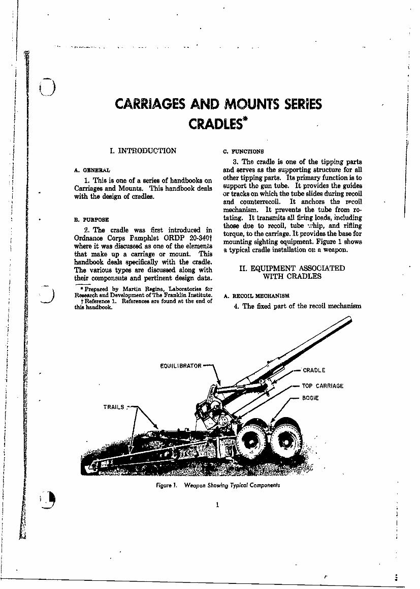
4
CARRIAGES AND MOUNTS SERIES
CRADLES*
I. INTRODUCTION c. FUNCTIONS
3. The cradle is one of the tipping partsA. GENERAL and serves as the supporting structure for all
1. This is one of a series of handbooks on other tipping parts. Its primary function is toCarriages and Mounts. This handbook deals support the gun tube. It provides the guides
with the design of cradles, or tracks on which the tube slides during recoiland counterrecoil. It anchors the recoilmechanism. It prevents the tube from ro-
B. PURPOSE tating. It transmits all firing loads, including2. The cradle was fist introduced in those due to recoil, tube whip, and rifling2.dnThe Coradle asphlt inrduc in3 torque, to the carriage. It provides the base for
Ordnance Corps Pamphlet ORDP 20-340t mounting sighting equipment. Figure 1 showswhere it was discussed as one of the elemensthat make up a carriage or mount. This atypical cradle installation on a weapon.
handbook deals specifically with the cradle.The various types are discussed along with II. EQUIPMENT ASSOCIATEDtheir components and pertinent design data. WITH CRADLES
* Prepared by Martin Regina, Laboratories forResearch and Development of The Franklin Institute. A. RECOIL MECHANISM
t Reference 1. References are found at the end ofthis handbook. 4. The fixed part of the recoil mechanism
EQUILIBRATOR CRADLE
BOI
Figure 1. Weapon Showing Typical Components
1 i
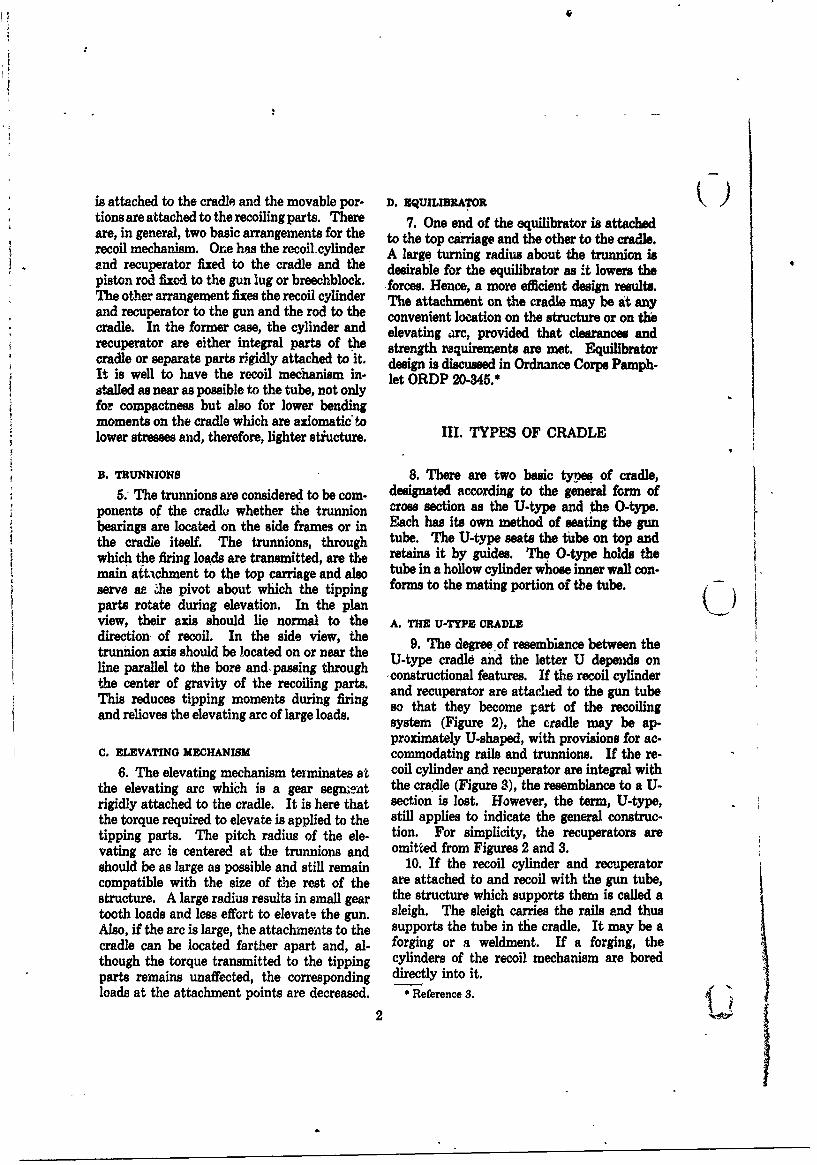
is attached to the cradle and the movable por- D. EqUILIBRATOR )tions are attached to the recoiling parts. There 7. One end of the equilibrator is attachedare, in general, two basic arrangements for the to the top carriage and the other to the cradle.recoil mechanism. One has the recoil cylinder A large turning radius about the trunnion isand recuperator fixed to the cradle and the desirable for the equilibrator as -t lowers thepiston rod fixed to the gun lug or breechblock. forces. Hence, a more efficient design results.The other arrangement fixes the recoil cylinder The attachment on the cradle may be at anyand recuperator to the gun and the rod to the convenient location on the structure or on thecradle. In the former case, the cylinder and elevating arc, provided that clearances andrecuperator are either integral parts of the strength requirements are met. Equilibratorcradle or separate parts rigidly attached to it. design is discussed in Ordnance Corps Pamph-It is well to have the recoil mechanism in. let ORDP 20.345.*stalled as near as possible to the tube, not onlyfor compactness but also for lower bendingmoments on the cradle which are axiomatic tolower stresses and, therefore, lighter stiucture. III. TYPES OF CRADLE
B. TRUNNIONS 8. There are two basic types of cradle,5. The trunnions are considered to be com- designated according to the general form of
ponents of the cradlju whether te trunnion cross section as the U-type and the O-type.bearings are located on the side frames or in Each has its own method of seating the gunthe cradle itself. The trunnions, through tube. The U-type seats the tube on top andwhich the firing loads are transmitted, are the retains it by guides. The 0-type holds themain att-chment to the top carriage and also tube in a hollow cylinder whose inner wall con-serve ae le pivot about which the tipping forms to the mating portion of the tube.parts rotate during elevation. In the plan(_view, their axis should lie normal to the A. THE U-TYPE CRADLEdirection. of recoil. In the side view, the 9. The degree of resembiance between thetrunnion axis should be located on or near the U-type cradle and the letter U depends online parallel to the bore and. passing through constructional features. If the recoil cylinderthe center of gravity of the recoiling parts. and recuperator are attached to the gun tubeThis reduces tipping moments during firing so that they become part of the recoilingand relioves the elevating arc of large loads, system (Figure 2), the cradle may be ap-
proximately U-shaped, with provisions for ac-C, ELEVATING MECHANISM commodating rails and trunnions. If the re-
6. The elevating mechanism terminates st coil cylinder and recuperator are integral withthe elevating are which is a gear segnmat the cradle (Figure 3), the resemblance to a U-rigidly attached to the cradle. It is here that section is lost. However, the term, U-type,the torque required to elevate is applied to the still applies to indicate the general construc-tipping parts. The pitch radius of the ele- tion. For simplicity, the recuperators arevating arc is centered at the trunnions and omitted from Figures 2 and 3.should be as large as possible and still remain 10. If the recoil cylinder and recuperatorcompatible with the size of the rest of the are attached to and recoil with the gun tube,structure. A large radius results in small gear the structure which supports them is called atooth loads and less effort to elevate the gun. sleigh. The sleigh carries the rails and thusAlso, if the arc is large, the attachments to the supports the tube in the cradle. It may be acradle can be located farther apart and, al- forging or a weldment. If a forging, thethough the torque transmitted to the tipping cylinders of the recoil mechanism are boredparts remains unaffected, the corresponding directly into it.loads at the attachment points are decreased. * Reference 3.
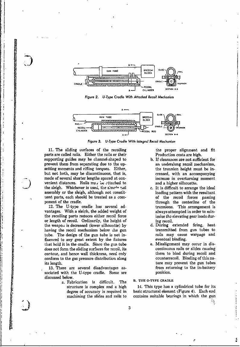
A. -
BREECUH
CRADLE -TUNO
CY~mNER \ :\x \ x~x 'RCOILRO
A-1 CYLINDER SECT.OR A-A
Figure 2. U-Type Cradle With Attached Recoil Mechanism
A -
GUNTUBE BREECH
RAIL-
CYLINDER ECOIL ROD
A SECTIONi A-A
Figure~ 3. (J.Type Cradle With Integral Recoil Mechanism
11. The sliding surfaces of the recoiling the proper alignment and fitparts are called rails. Either the rails or their Production costs are high.supporting guides may be channel-shaped to b. If clearances are not sufficient forprevent them from separating due to the up- an underslung recoil mechanism,setting moments and rifling torques. Either, the trunnion height must be in-but not both, may be discontinuous, that is, creased, with an accompanyingmade of several shorter lengths spaced at con- increase in overturning momentvenient distances. Rails may Le ,ttached to and a higher silhouette.the sleigh. Whichever is used, the s'm irl rail c. It is difficult to arrange the idealassembly or the sleigh, although not constit- loading pattern with the resultantuent parts, each should be treated as a corn- of the recoil forces passingponent of the cradle. through the centerline of the
12. The U-type cradle has several ad- trunnions. This arrangement isvantages. With a sleipgh, the added weight of always attempted in order to min-the recoiling parts reduces either recoil force imize the elevating gear loads dur-or length of recoil. Ordinarily, the height of ing recoil.the weapoa is decreased (lower silhouette) by d. During extended firing, heathaving the recoil mechanism below die gun transmitted from gun tubes totube. The design of the gun tube is not in- rails may cause warpage andfluenced to any great extent by the fixtures eventual binding.that hold it in the cradle. Since the gun tube e. Misalignment may occur in dis-does not form the sliding surfaces for recoil, its continuous rails or slides causingcontour, and hence wall thickness, need only them to bind during recoil andconform to the gas pressure distribution along counterrecoil. Binding of this na-its length. ture may prevent the gun tubes
13. There are several disadvantages as- from returning to the in-batterysociated with the U-type cradle. Some are position.discussed below.
a. Fabrication is difficult. The B. THE 0-TYPE CRADLE
structure is complex and a high 14. This type has a cylindrical tube for itsdegree of accuracy is required in basic structural element (Figure 4). Each endmachining the sliles and rails to contains suitable bearings in which the gun
3
tt*
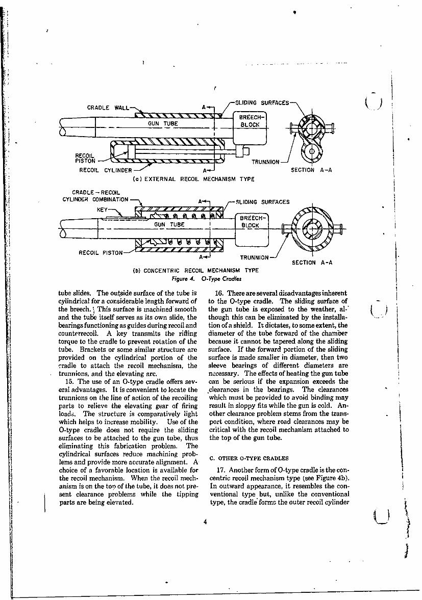
I -. -SLIDING SURFACES
REISON TRUNNIONRECOIL CYLINDER SECTION A-A
(a) EXTERNAL RECOIL MECHANISM TYPE
CRADLE - RECOILCYLINDER COMBINATION-A SLIDING SURFACES
__ __.k _. -- t rBREECH:GUNTUB TRION
REC OIL PISTO N A TR UN NIO
SECTION A-A(b) CONCENTRIC RECOIL MECHANISM TYPE
Figure 4. 0-Type Cradles
tube slides. The outside surface of the tube is 16. There are several disadvantages inherentcylindrical for a considerable length forward of to the 0-type cradle. The sliding surface ofthe breech. This surface is machined'smooth the gun tube is exposed to the weather, al-.and the tube itself serves as its own slide, the though this can be eliminated by the installa- .. "bearings functioning as guides during recoil and tion of a shield. It dictates, to some extent, thecounterrecoil. A key transmits the rifling diameter of the tube forward of the chambertorque to the cradle to prevent rotation of the because it cannot be tapered along the slidingtube. Brackets or some similar structure are surface. If the forward portion of the sliding
j provided on the cylindrical portion of the surface is made smaller in diameter, then twocradle to attach the recoil mechanism, the sleeve bearings of different diameters aretrunnions, and the elevating arc. necessary. The effects of heating the gun tube
15. The use of an 0-type cradle offers sev- can be serious if the expansion exceeds theeral advantages. It is convenient to locate the clearances in the bearings. The clearancestrunnions on the line of action of the recoiling which must be provided to avoid binding mayparts to relieve the elevating gear of firing result in sloppy fits while the gun is cold. An-loads. The structure is comparatively light other clearance problem stems from the trans-which helps to increase mobility. Use of the port condition, where road clearances may be0-type cradle does not require the sliding critical with the recoil mechanism attached tosurfaces to be attached to the gun tube, thus the top of the gun tube.eliminating this fabrication problem. Thecylindrical surfaces reduce machining prob- C. OTHER 0-TYPE CRADLESlems and provide more accurate alignment. A-choice of a favorable location is available for 17. Another form of 0-type cradle is the con-the recoil mechanism. When the recoil mech- centric recoil mechanism type (see Figure 4b).anism is on the tot, of the tube, it does not pre- In outward appearance, it resembles the con-S sent clearance problems while the tipping ventional type but, unlike the conventional
parts are being elevated, type, the cradle' form the outer recoil cylinder
4,
IIGI
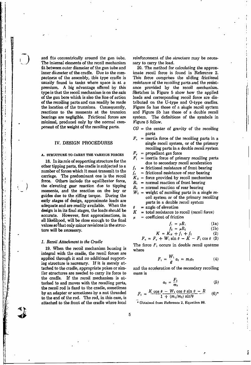
) and fits concentrically around the gun tube. reinforcement of the structure may be neces-The internal elements of the recoil mechanism sary to carry the load.fit between outer diameter of the gun tube and 20. The method for calculating the approx-inner diameter of the cradle. Due to the corn- imate recoil force is found in Reference 2.pactne-s of the assembly, this type cradle is This force comprises the sliding frictionalusually found in tanks where space is at a resistance of the recoiling parts and the resist-premium. A big advantage offered by this ance provided by the recoil mechanism.type is that the recoil mechanism is on the axis Sketches in Figure 5 show how the appliedof the gun bore which is also the line of action loads and corresponding recoil force are dis-of the recoiling parts and can readily be made tributed on the U-type and O-type cradles.the location of the trunnions. Consequently, Figure 5a has those of a single recoil syztemreactions to the moments at the trunnion and Figure 5b has those of a double recoilbearings are negligible. Frictional forces are system. The definitions of the symbols inminimal, produced only by the normal corn- Figure 5 follow.ponent of the weight of the recoiling parts. CG = the center of gravity of the recoiling
partsF,, = inertia force of the recoiling parts in a
IV. DESIGN PROCEDURES single recoil system, or of the primaryrecoiling parts in a double recoil system
A. STRUCTURE TO CARRY THE VARIOUS FORCES F, = propellant gas force
18. In its role of supporting structure for the F, = inertia force of primary recoiling partsother tiping arts , ro e c e si subcted o te due to secondary recoil acceleration
other tipping parts, the cradle is subjected to a = frictional resistance of front bearingnumber of forces which it must transmit to the i, = frictional resistance of rear bearingcarriage. The predominant one is the recoil Kit = force provided by recoil mechanismforce. Others include the equilibrator force, R, = normal reaction of front bearingthe elevating gear reaction due to tipping R2 = normal reaction of rear bearingmoments, and the reaction on the key or W1 = weight of recoiling parts in a single re-guides due to the rifling torque. During the coil system or of the primary recoilingearly stages of design, approximate loads are parts in a double recoil systemadequate and are readily available. When the 0 = angle of elevationdesign is in its final stages, the loads should be K - total resistance to recoil (recoil force)accurate. However, first approximations, inall likelihood, will be close enough to the final = of frictionvalues sothat only minor revisions in the struc- ,= R (la)ture will be necessary. h uR2 (1b)
K =Ku +fi+f2 (2)F. F,,+-t- Wsin 0-K- F, cos 0 (3)1. Recoil Attachment to the Cradle
The force F, occurs in double recoil systems19. When the recoil mechanism housing is where
integral with the cradle, the recoil forces are W,applied through it and no additional support- F, = a2 = m1a2 (4)ing structure is necessary. If it is merely at- gtached to the cradle, appropriate yokes or sim- and the acceleration of the secondary recoilingilar structures are needed to carry its force to mass isthe cradle. If the recoil mechanism is at- F2tached to and moves with the recoiling parts, a2= (5)the recoil rod is fixed to the cradle, sometimes 2
by an adapter or sometimes by a nut threaded F2 K cos 0 - W, cos 0 sin 0- Rto the end of the rod. The rod, in this case, is 1 + (M/Mr) sin0 (6)*
attached to the front of the cradle where local * Obtained from Reference 2, Equation 88.
5V
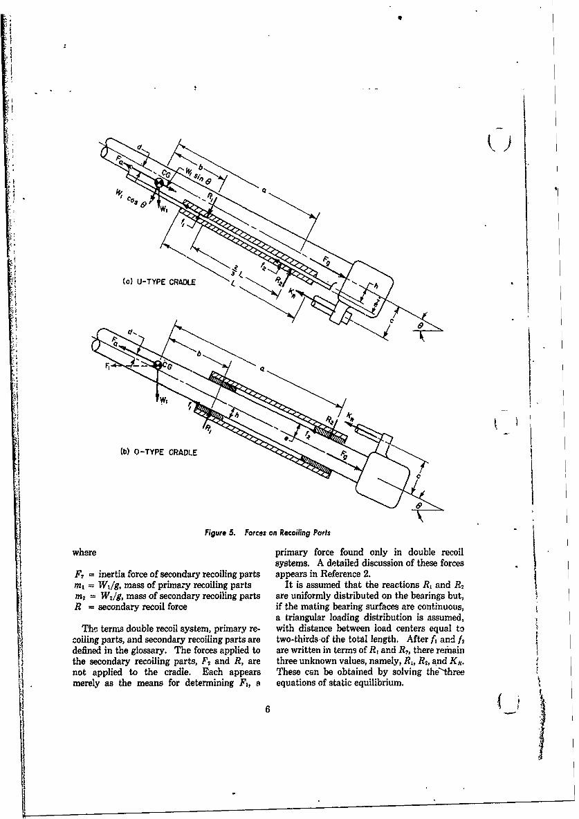
49
'IA
iii (a) U-TYPE CRADLE
F__
'I (b) 0-TYPE CRADLE
Figure 5. Forces on Recoiling Parts
where primary force found only in double recoilsystems. A detailed discussion of these forces
F2 = inertia force of secondary recoiling parts appears in Reference 2.Mt = W1 /g, mass of primazy recoiling parts It is assumed that the reactions R, and R2
m2 = W 2/g, mass of secondary recoiling parts are uniformly distributed on the bearings but,R = secondary recoil force if the mating bearing surfaces are continuous,
a triangular loading distribution is assumed,The terms double recoil system, primary re- with distance between load centers equal to
coiling parts, and secondary recoiling parts are two-thirds of the total length. After ft and f2defined in the glossary. The forces applied to are written in terms of R, and R?, there remainthe secondary recoiling parts, F2 and R, are three unknown values, namely, R1, R2, and Kn.not applied to the cradle. Each appears These can be obtained by solving the'threemerely as the means for determining F1, a equations of static equilibrium.
1 - 6
L . .... .
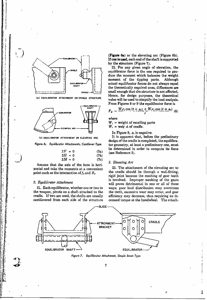
) (Figure 6a) or the elevating arc (Figure 6b).t.'. If one is used, each end of the shaft is supported
I1 by the structure (Figure 7).22. For any given angle of elevation, the
-- uilibrator force is the one required to pro-Iduce the moment whichbancstewih
I moment of the tipping parts. AlthoughEOUILIBRATOR actual equilibrator forces do not always equal
S1HAT the theoretically required ones, differences areACRADLE small enough that the structure is not affected.
(a) EQUILIBRATOR ATTACHMENT ON CRADLE STRUCTURE Hence, for design purposes, the theoreticalLSTRUTRE value will be used to simplify the load analysis.
From Figures 8 or 9 the equilibrator force isEQ@UILI BRATOR"-'
SHAF WinL cos (0 + ~)+ WXr, COS (0 + 0'2)EQW.SRATOR F4- (8)
whereW, = weight of recoiling parts
ELEVATIPG ARC W, = weir it of cradle.
In Figure 8, 42 is negative.(b EQUILIBRATOR ATTACHMENT ON ELEVATING ARC It is apparent-that, before the preliminary
design of the cradle is completed, the equilibra-Figure 6; Equilibrator Attachments, Cantilever Type tor geometry, at least a preliminary one, must
be determined in order to compute its forceXV = 0 (7a) (see Reference 3).2;H = 0 (7b)IM = 0 (7c)
Assume that the axis of the bore is hori- 3. Elevating Arc
zontal and take the moments at a convenient 23. The attachment of the elevating arc topoint such as the intersection of f2 and R2. the cradle should be through a well-fitting,
rigid joint because the meshing of gear teethis involved. Improper meshing of the gears
2. Equilibrator Attachment will prove detrimental in one or all of three21. Each equilibrator, whether one or two to ways; poor load distribution may overstress
the weapon, pivots on a shaft attached to the the teeth, excessive wear may occur, and gearcradle. If two are used, the shafts are usually efficiency may decrease, thus requiring an in-cantilevered from each side of the structure creased torque at the handwheel. The attach-
SSLI DE ---
I ATTACHMENT--- 0 0 CRADLE, = ) : BRACKET '
EQUILIBRATOR SHAFT EQUILIBRATOR
Figure 7. Equilibrator Attachment, Simple Beam Type
qi~4 7
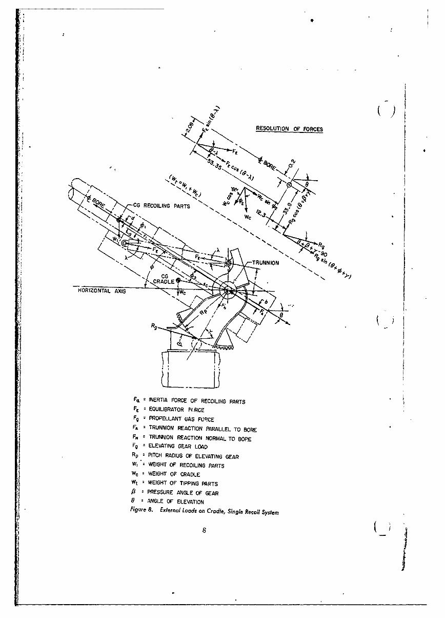
IS
RESOLUTION OF FORCES
G RECOILING P ARTSs
--HORITRUNNIO AXS 11e
)"
"N: NRTAF/CEO RCILN PARTS " !N
,C:EQIRALE FC
Fg PROPELLANT UAS FORCE
FA =TRUNNION REACTION PARALLEL TO BOREFN TRUNNION REACTION NORMAL TO BOPE
Fg ELEVATING GEAR LOADRp =PITCH RADIUS OF ELEVATING GEARW, WEIGHT OF RECOILING PARTSW WEIGHT OF CRADLE
Wt =WEIGHT OF TIPPING PARTS.PRESSURE ANGLE OF GEAR
- NI8 ALE EEAIN
HORIONTA AXI ExenlLaso rdeSnl eolSse
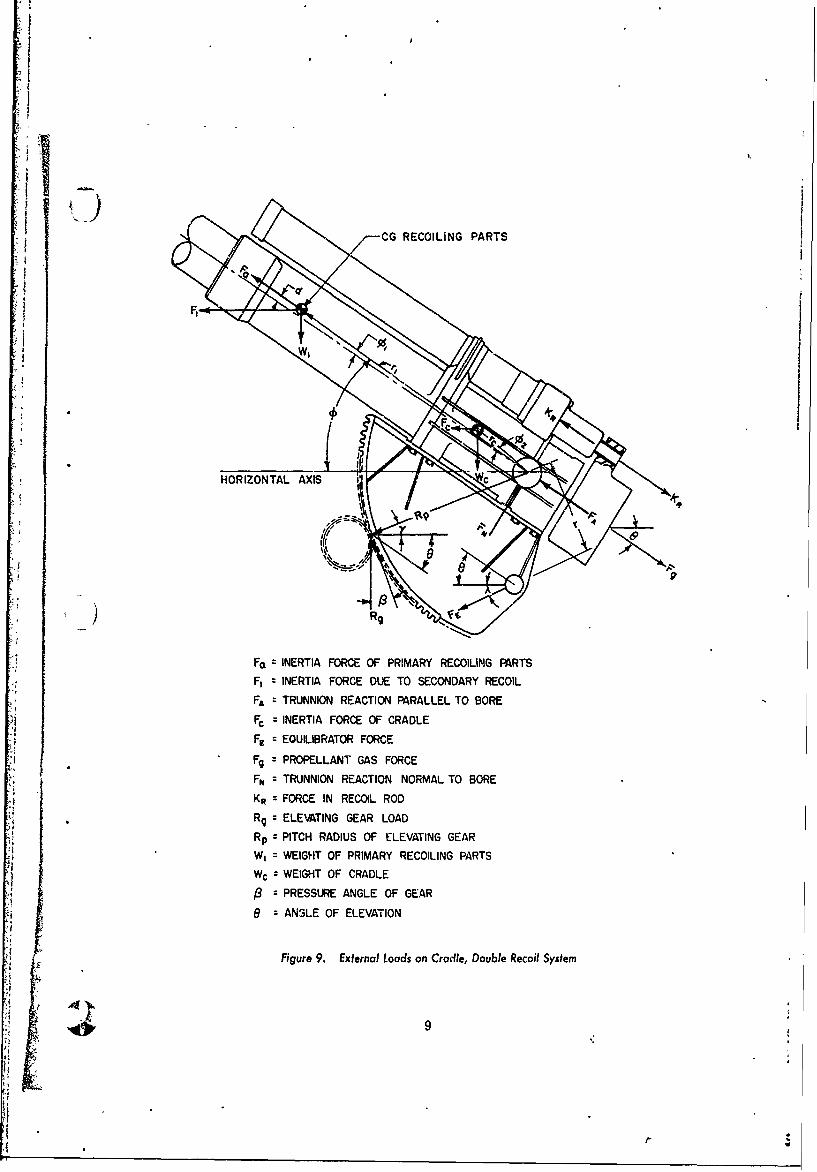
I
)
NETAF CG RECOILING PARTS
W,
HORIZONTAL AXIS C Pg
Fa INERTIA FORCE OF PRIMARY RECOILING PARTS
F, " INERTIA FORCE DUE TO SECONDARY RECOIL
FA TRUNNION REACTION PARALLEL TO BORE
Fc =INERTIA FORCE OF CRADLE
FE : EQUILIBRATOR FORCE
Fg = PROPELLANT GAS FORCEFpM TRUNNION REACTION NORMAL TO BORE
K: z FORCE IN RECOIL ROD
R9 z ELEVATING GEAR LOAD
Rp = PITCH RADIUS OF ELEVATING GEAR
W, = WEIGHT OF PRIMARY RECOILING PARTSW c = WEIGHT OF CRADLE
PRESSURE ANGLE OF GEAR
9 = ANSLE OF ELEVATION
Figure 9. External Loads on Cradle, Double Recoil System
9
rIg
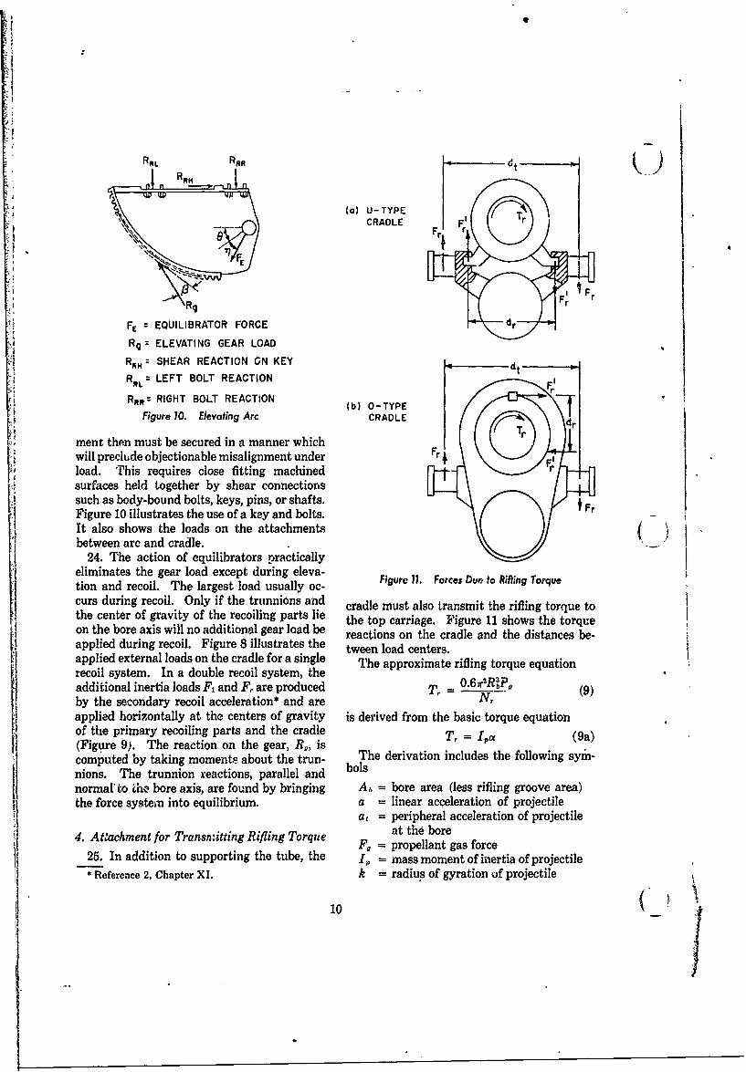
RRL RR t
(a) U-TYPE_._CRADLE F i Frr
R9 F
FE EQUILIBRATOR FORCE
Rq = ELEVATING GEAR LOAD
RAN: SHEAR REACTION ON KEY dt
RAL: LEFT BOLT REACTION
Rft= RIGHT BOLT REACTION (b) 0-TYPEFigure 10. Elevating Arc CRADLE
ment then must be secured in a manner whichwill preclude objectionable misalignment under Frload. This requires close fitting machinedsurfaces held together by shear connectionssuch as body-bound bolts, keys, pins, or shafts. FrFigure 10 illustrates the use of a key and bolts.It also shows the loads on the attachments
between arc and cradle.24. The action of equilibrators practically
eliminates the gear load except during eleva-tion and recoil. The largest load usually oc-curs during recoil. Only if the trunnions and cradle must also transmit the rifling torque tothe center of gravity of the recoiling parts lie the top carriage. Figure 11 shows the torqueon the bore axis will no additional gear load be reactions on the cradle and the distances be-applied during recoil. Figure 8 illustrates the tween load centers.applied external loads on the cradle for a single The approximate rifling torque equationrecoil system. In a double recoil system, theadditional inertia loads F, and F, are produced T- 0"2RPU(9)by the secondary recoil acceleration* and are N(applied horizontally at the centers of gravity is derived from the basic torque equationof the primary recoiling parts and the cradle T, = 1, (9a)(Figure 9). The reaction on the gear, R,, iscomputed by taking moments about the trun- The derivation includes the following syin-
nions. The trunnion reactions, parallel and bols
normal' to Lhe bore axis, are found by bringing Ab = bore area (less rifling groove area)the force system into equilibrium, a = linear acceleration of projectile
a, = peripheral acceleration of projectile
4. Aachment for Transrnitting Rifling Torque at the bore25. In addition to supporting the tube, the I,, = mass moment of inertia of projectile
* Reference 2, Chapter XI. k = radius of gyration of projectile 1I
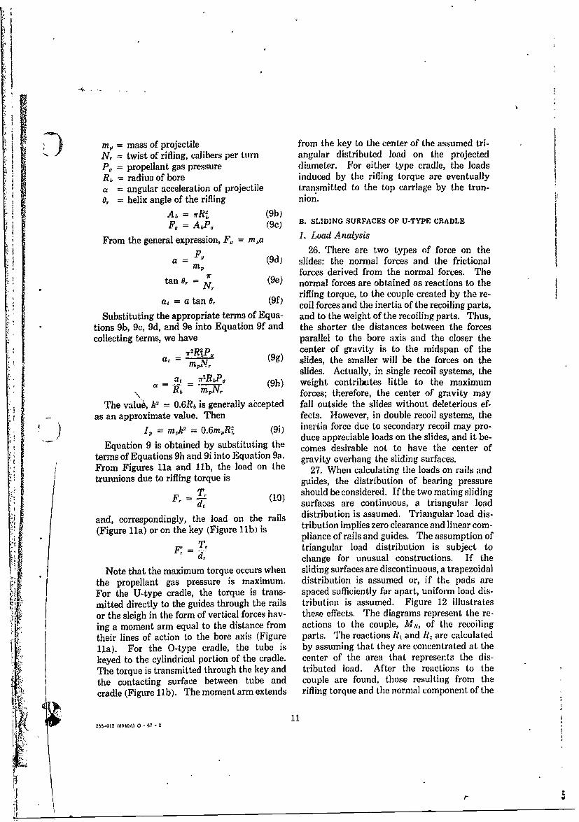
7), mass of projectile from the key to the center of the assumed tri-N, = twist of rifling, calibers per turn angular distributed load on the projectedP, = propellant gas pressure diameter. For either type cradle, the loadsR,= radius of bore induced by the rifling torque are eventuallya angular acceleration of projectile transmitted to the top carriage by the trun-0, = helix angle of the rifling nion.
A= rR, (9b)F0 = Ab!'0 (9c) B. SLIDING SURFACES OF U-TYPE CRADLE
1. Load AnalysisFrom the general expression, F, = m,a1
F. 26. There are two types of force on thea = (9d) slides: the normal forces and the frictional
7rf forces derived from the normal forces. The
tan 0, (9e) normal forces are obtained as reactions to the
rifling torque, to the couple created by the re-al = a tan 0, (9f) coil forces and the inertia of the recoiling parts,
Substituting the appropriate terms of Equa- and to the weight of the recoiling parts. Thus,tions 9b, 9c, 9d, and 9e into Equation 9f and the shorter the distances between the forcescollecting terms, we have parallel to the bore axis and the closer the
72R2P center of gravity is to the midspan of thea, =mN (9g) slides, the smaller will be the forces on the
slides. Actually, in single recoil systems, thea 7xlRbP0 (9h) weight contributes little to the maximum
.. a = , = m forces; therefore, the center of gravity may
The valu6, k2 = 0.6Rb is generally abcepted fall outside the slides without deleterious ef-- as an approximate value. Then fects. However, in double recoil systems, the
1, = mlk = 0.6m,,R, (9i) inertia force due to secondary recoil may pro-duce appreciable loads on the slides, and it be-
Equation 9 is obtained by substituting the comes desirable not to have the center of
terms of Equations 9h and 9i into Equation 9a. gravity overhang the sliding surfaces.From Figures Ila and llb, the load on the 27. When calculating the loads on rails andtrunnions due to rifling torque is guides, the distribution of bearing pressure
T, should be considered. If the two mating sliding
F d, (10) surfaces are continuous, a triangular load
and, correspondingly, the load on the rails distribution is assumed. Triangular load dis-(Figure !ha) or on the key (Figure lbl is tribution implies zero clearance and linear com-
pliance of rails and guides. The assumption of
T, triangular load distribution is subject tod, change for unusual constructions. If the
Note that the maximum torque occurs when sliding surfaces are discontinuous, a trapezoidal
the propellant gas pressure is maximum. distribution is assumed or, if the pads are
For the U-type cradle, the torque is trans- spaced sufficiently far apart, uniform load dis-
mitted directly to the guides through the rails tribution is assumed. Figure 12 illustratesor the sleigh in the form of vertical forces hay- these effects. The diagrams represent the re-
ing a moment arm equal to the distance from actions to the couple, M,., of the recoilingtheir lines of action to the bore axis (Figure parts. The reactions R, and R2 are calculated
lla). For the 0-type cradle, the tube is by assuming that they are concentrated at the
keyed to the cylindrical portion of the cradle. center of the area that represents the dis-
The torque is transmitted through the key and tributed load. After the reactions to the
the contacting surface between tube and couple are found, those resulting from the
cradle (Figure llb). The moment arm extends rifling torque and the normal component of the
0 8112M,-012 (8040A) 0 -67 - 2
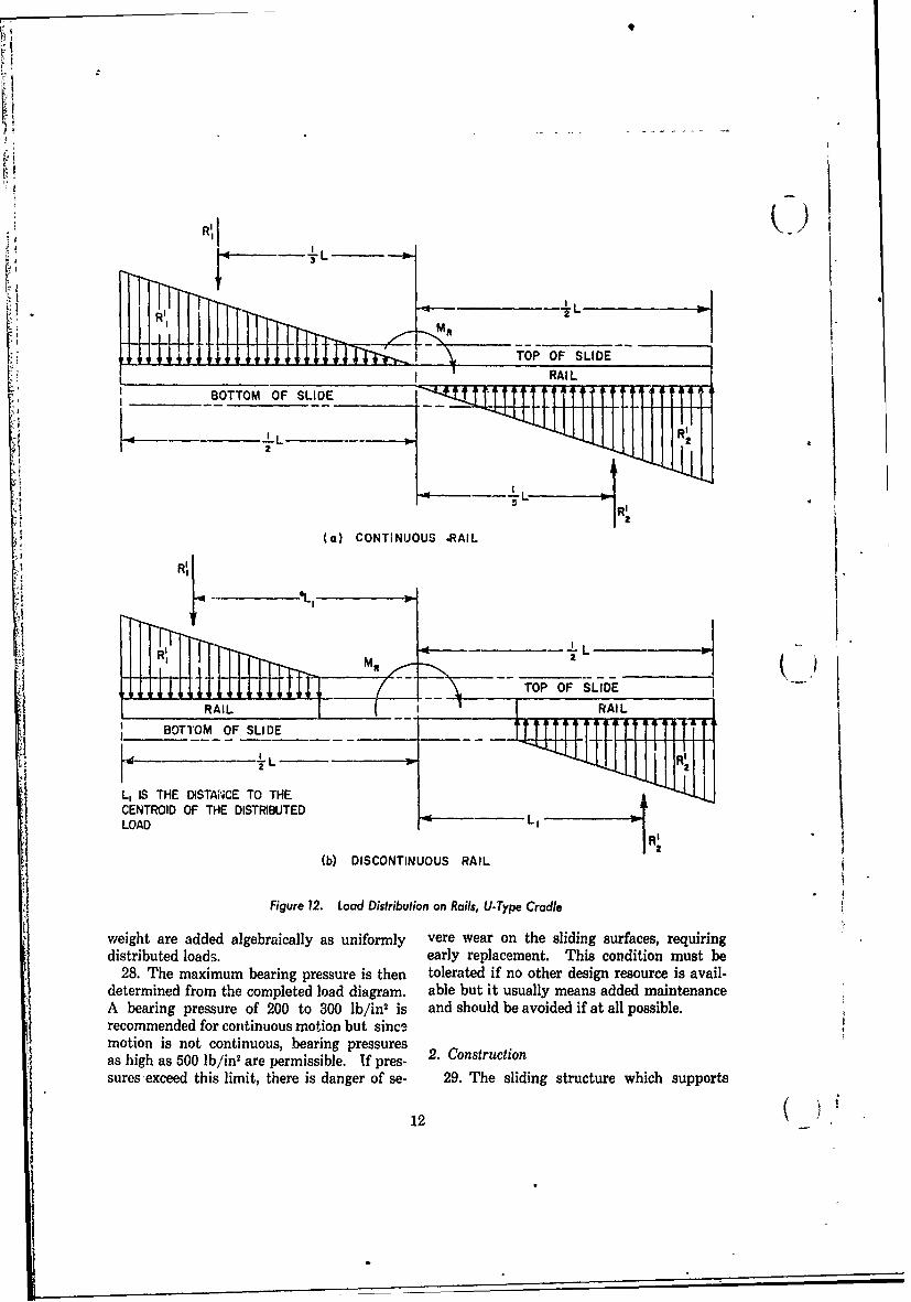
LLR~IRAIL
SBOTTOM OF SLIDE TT1
L L R'
2
(a) CONTINUOUS -RAIL
."LL
FTOP OF SLIDE i--RAIL RAI L
1'_BOTTOM -OF SLI DE _T - TTT
L, IS THE DISTA'NCE TO THECENTROID OF THE DISTRIBUTED
,LLOAD L IR2(b) DISCONTINUOUS RAIL
Figure 2. Load Distribution on Rails, UType Cradle
weight are added algebraically as uniformly vere wear on the sliding surfaces, requiringdistributed loads. early replacement. This condition must be
28. The maximum bearing pressure is then tolerated if no other design resource is avail-determined from the completed loadl diagram. able but it usually means added maintenanceA bearing pressure of 200 to 300 lb/in' is and should be avoided if at all possible.recommended for continuous motion but since,motion is not continuous, .bearing pressures 2.Cntuioas high as 500 lb/in, are permissible. If pres-2.ontuinsuresexceed this limit, there is danger of se- 29. The sliding structure which supports
12_ _ _ _
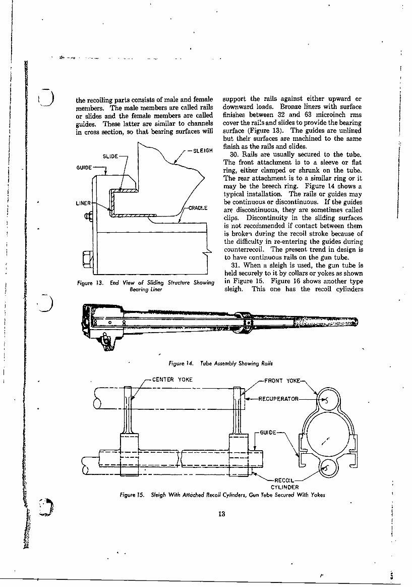
-k
the recoiling parts consists of male and female support the rails against either upward or
members. The male members are called rails downward loads. Bronze liners with surface
or slides and the female members are called finishes between 32 and 63 microinch rms
guides. These latter are similar to channels cover the rai!s and slides to provide the bearingin cross section, so that bearing surfaces will surface (Figure 13). The guides are unlined
but their surfaces are machined to the same-SLEIGH finish as the rails and slides.-SLIG 30. Rails are usually secured to the tube.
GUIDE The front attachment is to a sleeve or flatGUIDE-'--' / ring, either clamped or shrunk on the tube.
The rear attachment is to a similar ring or it
may be the breech ring. Figure 14 shows atypical installation. The rails or guides may
LINER- / be continuous or discontinuous. If the guides?CRAD~.E are discontinuous, they are sometimes called
clips. Discontinuity in the sliding surfacesis not recofnmended if contact between themis broke-i during the recoil stroke because ofthe difficulty in re-entering the guides during
S counterrecoil. The present trend in design isto have continuous rails on the gun tube.
31. When a sleigh is used, the gun tube isheld securely to it by collars or yokes as shown
Figure 13. End View of Sliding Structure Showing in Figure 15. Figure 16 shows another typeBearing Liner sleigh. This one has the recoil cylinders
Figure 14. Tube Assembly Showing Rails
CENTER YOKE FRONT YOKE
_i i RECUPERATOR
SI t
--
~GU -- 1 -:- -- -
RECO:LCYLINDER
Figure 15. Sleigh With Attached Recoil Cylinders, Gun Tube Secured With Yokes
13
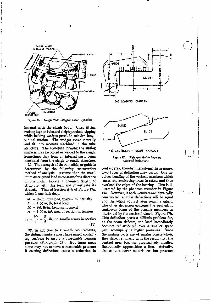
LOCKING WEDGES ' ( )IN LOCKING POSITION
WEDGE SCREWS Pl B
GUIDE cUIO
t SLIDE _-RECUPRERATOR % ,
(a) LOADING DIAGRAM
PCCOIL
/WEDGE CYLINDERSLOCKING SOLT
Figure 16. Sleigh With Integral Recoil Cylinders
integral with the sleigh body. Close fitting
mating lugs on tube and sleigh preclude tippingwhile locking wedges preclude relative longi-tudinal motion. The wedges move laterallyand fit into recesses machined in the tubestructure. The structure forming the sliding (surfaces may be bolted or welded to the sleigh. (b) CANTILEVER BEAM ANALOGYSometimes they form an integral part, being Figure 17. Slide and Guide Showingmachined from the sleigh or cradle structure. Assumed Defections
32. The strength of the rail, slide, or guide isdetermined by the following conservativ-2 contact area, thereby intensifying the pressure.method of analysis. Assume that the maxi- Two types of deflection may occur, One in-mum distributed load is constant for a distance volves bending of the vertical members whichof one inch. Isolate a one-inch length of causes the contacting areas to rotate and thusstructure with this load and investigate its overload the edges of the bearing. This is il-strength. Thus at Section A-A of Figure 17a, lustrated by the phantom member in Figurewhich is one inch deep, 17a. However, if both members are identically
w = lb/in, unit load, maximum intensity constructed, angular deflections will be equal
F = 1 X w, lb, total load and the whole contact area remains intact.
M = Fd, lb-in, bending moment The other deflection concerns the equivalent
A = 1 X a, in 2, area of section in tension cantilever beam of the bearing members asillustrated by the sectional view in Figure 17b.
= c+ -, lb/in2, tensile stress in section This deflection poses a difficult problem for,I as the beam deflects, the load immediately
(I1) becomes redistributed over a smaller space33. In addition to strength requirements, with accompanying higher pressures. Since
the sliding members must have ample contact- the mating parts are of similar construction,ing surfaces to insure a reasonable bearing they deflect similarly with the result that thepressure (Paragraph 28). But large areas contact area becomes progressively smaller,alone may not achieve a reasonable pressure theoretically approaching a line. Actually,if ensuing deflections cause a reduction in line contact never material'zes but pressure
14
A
will peak excessively because of the deflections. slides in the keyways of each bearing. Al-A means of circumventing peak pressures em- though the rifling torque is applied for only aploys the practice of providing enough flexi- short recoil distance, the key should be longbiiity in the structure to enable the deflection enough to maintain contact with the bearingsof one mating surface to conform to the deflec- at all positions of the recoil stroke so that notion of the other, thus maintaining the original difficulty in alignment develops during coun-contact area. But this type of structure is not teriecoil.always feasible and may not be applicable tocradle design. If not, one must resort to ap-proximation methods that are available for D. EFFECT OF FRICTION ON SLIDING SURFACESdetermining the required bearing area. Onesuch method assumes a uniform load distribu- 36. Frictional forces, as such, are not a
tion with the maximum design pressure limited srucusregt in oth spects, theto 50 pi (se Pragrph 8).structural strength. In other aspects, theyto 500 psi (see Paragraph 28. present serious problems. For design analysis,
the present practice is to use a coefficient ofC. SLIDING SURFACE OF O-TYPE CRADLE friction of 0.15*. Friction resists recoil and
thus forms part of the recoil force. Theoret-34. The general discussions on the sliding ically, it does not matter whether the recoil
surfaces of the U-type cradle apply as well to force is generated by friction or by the recoilthose of the 0-type cradle. It is advan- mechanism. However, it is desirable to keeptageous to have the center of gravity of the friction to a minimum by proper lubricationrecoiling parts located as near as possible to because wear and eventual damage to thethe bearings. For the load analysis, the bear- sliding surfaces are less likely to occur. Also,ings are usually far enough apart to assume a frictional forces are somewhat of an unknownuniform load distribution. The tipping mo- value on exposed surfaces and may vary con-ment during recoil produces the largest loads siderably. If their maximum value is small,on the bearings. A bearing pressure of 200 to it will constitute only a small part of the total300 lb/in is desirable but pressure should notexced 50 l/in (se Paagrph 8).The recoil force and will have only a slight effect onexceed 500 lb/in2 (see Paragraph 28). The the functioning of the recoil mechanism.O-type differs in that the gun tube is keyed tothe cradle and in that the reaction to therifling torque is transmitted by the key, not by E. EFFECT OF TEMPERATURE VARIATION ONthe sliding surfaces (see Figure 11). Because SLIDING SURFACESthe structure must be held to reasonable pro-portions, and the sliding surface offered by the 37. Artillery is (mployed in both desert and
key is limited in area, the bearing pressures arctic climates. Changes in the ambienthere may be much higher than on other sliding temperature will shrink or expand the struc-surfaces. However, due to the extremely short ture. If made of like material, all componentsduration of the rifling torque, allowable bear- will be affected equally, causing no relative
ing pressures may be high. After incorporating displacement among them. However, if theSthe fator of safety, they nmy approach the structural members are of unlike material,bearing strength of the material, their rates of expansion will differ and this may
35. The construction of the sliding surfaces prove dileterious sinply by reducing clear-
of the O-type cradle is relatively simple. The ances between moving parts to the extent
primary structure is a cylinder in which the where binding impends. The sliding surfacesgun tube slides during recoil. A bronze bearing of cradles must be of different materials be-
at each end and a straight portion of the gun cause two mating surfaces of like material
tube, machined to a 32 rms finish, provide the seldom provide compatible sliding properties.
sliding surfaces. Thus, the gun tube serves as Bronze makes an excellent sliding surface for
its own slide and the bearings serve as guides. steel. Its coefficient of linear expansion isThe key is usually secured to the gun tube and * Reference 4.
15
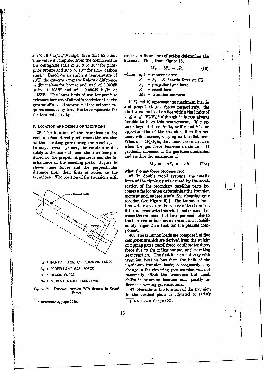
-
3.5 X 10-' in/in/F larger than that for ated. respect to these lines of action determines the j /This value is computed from the coefficients in womeait. Thus, from Figure 18,the centigrade scale of 16.8 X 10- 1 for phos-phor bronze and 10.5 X 10⁻¹ for 1.2% carbon MT bF, - aF, (12)steel.* Based on an ambient temperature of where a, b = moment arms70"F, the extreme ranges will show a difference F. F, -K, inertia force at CGin dimensions for bronze and steel of 0.00033 F, = propellant gas forcein/in at 165°F and of -0.00047 in/in at K = recoil force-65 0F. The lower limit of the temperature Mr = trunnion momentextremes because of climatic conditions hA the If F and F represent the maximum inertiagreater effect. However, neither extreme re- and propellant gas forces respectivery, the
hquires excessively loose fits to compensate for ideal trunnion location lies within the limits ofthe thermal activity b _Z a 4 (F/F,)b although it is not always
feasible to have this arrangement. If a ex-F. LOCATION AND DESIGN OF TRUNNIONS tends beyond these limits, or if a and b lie on
38. The location of the trunnions in the opposite sides of the tnmnion, then the mo-vertical plane directly influences the reaction ment will increase, varying as the distances.on the elevating gear during the recoil cycle. When a (F/F)b, the moment becomes zeroIn single recoil systems, the reaction is due when the gas ore becomes maximum. Itsolely to the moment about the trunnions pro- gradually increases as the gas force diminishesduced by the propellant gas force and the in- and reaches the maximum ofertia force of the recoiling peats. Figure 18 MT = -aF. = -aK (12a)shows these forces and the perpendicular Madistance from their lines of action to the when the gas force becomes zero.trunnions. The position of the trunnions with 39. In double recoil systems, the inertia
force of the tipping parts caused by the accel-eration of the secondary recoiling parts be-comes a factor when determining the trunnionmoment and, subsequently, the elevating gearreaction (see Figure 9).t The trurnion loca-tion with respect to the center of the bore haslittle influence with this additional moment be-
R cause the component of force perpendicular tothe bore center line has a moment arm consid-erably larger than that for the parallel com-ponent.
K40. The trunnion loads are composed of fivecomponents which are derived from the weightof tipping parts, recoil force, equilibrator force,force due to the rifling torque, and elevatinggear reaction. The first four do not vary with
FcL = INERTIA FORCE OF RECOILING PARTS trunnion location but form the bulk of themaximum trunnion loads; consequently, any
Fg = PROPELLANT GAS FORCE change in the elevating gear reaction will notK - RECOIL FORCE materially affect the trunnions but smallMT = MOMENT ABOUT TRUNNIONS shifts in trunnion location may greatly in-
fluence elevating gear reactions.Figure 18. Trunnion Location With Respect to Recoil 41. Sometimes the location of the trunnion
Forces in the vertical plane is adjusted to satisfy
* Reference 5, page 2239. t Reference 2, Chapter XI.
I ~16 _)
some structural requirement. For example, and the shear stress, r, at any line q. either on,when located below the bore center line, more or at a distance from, the neutral axis of thespace will be provided for an underslung recoil total section, ismechanism. Or, if they are located on thecenter line, structural symmetry is preserved. FrA d (14)Also, if the trunnions are on the center line, - -the sighting equipment will not have to becorrected for discrepancies due to an off-center where A. = area above the line qcorctfo t = thickness of section at qlocation. iisd = distance between the neutral
42. In the horizontal plane, it is advantage- axis of the section athe neuous to have the trunnions located equidistant axis of a d the neu-from the center line of the gun bore. Here, theobject is mainly one of symmetry. If sym- FT V. + F, resultant shear atmetry cannot be achieved, the cradle will be the section (see Figures 8 and 9)subjected to a direct load and a couple equal to I = moment of inertia of the sectionthe recoil force times the offset. Its vertical L = moment arm of trunnion meas-component 'ends to turn the weapon on its ured to center of bearingside. Its horto.ontal component tends to rotate M = FrL, bending momentthe cradle and top carriage. However, the basesupporting the top carriage is symmetrical withrespect to the bore and the loads revert to a G. STRENGTH REQUIREMENTSsymmetrical condition at this point. If any 45. Stresses are calculated for a cradle whichresidual horizontal moment persists, it is is assumed to be completely isolated from allrsisted at the traversing gear. This dL- other components of the gun. This approach iscussion does not include the rifling torque conservative because the stiffness associatedwhich is transmitted through the structure with gun tube and structural members whichwhile the projectile travels in the bore. ordinarily would lend strength to the cradle
43. When the distances from the bore to the is ignored.trunnions are unequal, the cradle must be 46. The general stresses of the main cradlemade larger to offset the effects of the un- structure are due to bending and direct shear.symmetrical loads and this eventually leads to However, at each point of load application,a heavier structure. In considering deflections, local stresses are present which may be greatersymmetry becomes definitely desirable. If than or may augment the general stress. Theboth sides of the cradle deflect Nqually, com- local areas are loaded by the recoil mechanism,pensation for misalignment during firing pre- the trunnion, and the elevating mechanismsnta lesser problems in fire control than if the through their attachments to the cradle.
two sides of the cradle deflected unequally. After the principal stresses have been found,In the first case, the gun tube would remain usually by conventional methods of stressessentially in line, while in the latter, it would analysis, the equivalent stress is determined.turn slightly askew. An accepted method for computing the
44. The size of the trunnion is usually dic- equivalent stress comes from the maximum-tated by required bearing dimensions. How- shear-stress theory of Tresca and Saintever, it should be investigated to determine its Venant* which states that yielding begins whenstrength in bending and shear. As a rule, the the largest difference of two principal stressestrunnion may be considered a short beam and equals the yield strength of the material, orthe stresses calculated according to the formu-las below, which can be found in any text on at - a2 = av (15)strength of materials. The bending stress is To be compatible with other components of
(MC the gun carriage, a factor of safety of 1.5 is rec-
I3 * Reference 6, Page 39.
17
tV
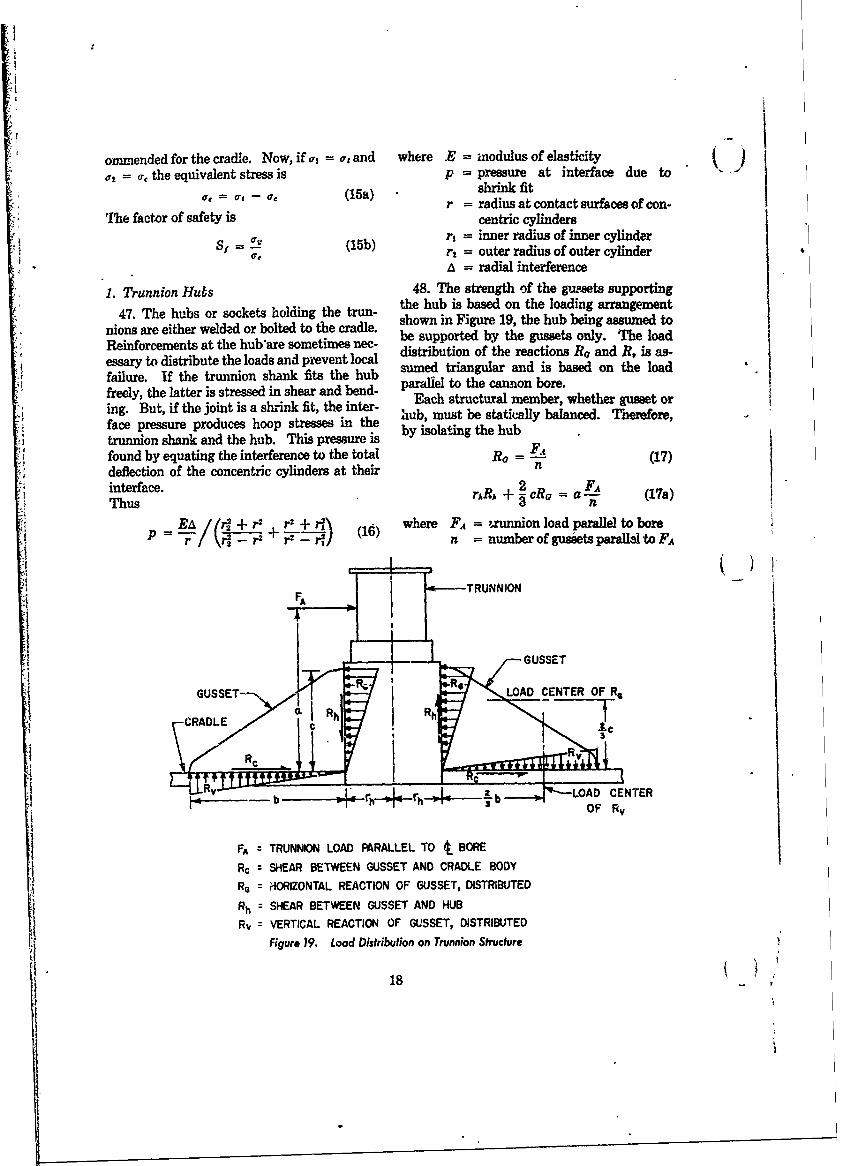
ommended for the cradle. Now, if al = or and where .E = modulus of elasticity (o,= , the equivalent stress is p = pressure at interface due to"(15a) shrink fit
r = radius at contact surfaces of con-
The factor of safety is centric cylindersr = inner radius of inner cylinderr, = outer radius of outer cylinder
= radial interference
1. Trunnion Hubs 48. The strength of the gusets supporting
47. The hubs or sockets holding the trun- the hub is based on the loading arrangement
nions are either welded or bolted to the cradle. shown in Figure 19, the hub being assumed to
Reinforcements at the hub are sometimes nee- be supported by the gussets only. The load
essary to distribute the loads and prevent lol distribution of the reactions Ro and R. is as-essryume tragua disriut the basds ann theen looad
failure. If the trunnion shank fits the hub u trigular and is based on the loadfreely, the latter is stressed in shear and bend- paraliel to the cannon bore.
ing. But, if the joint is a shrink fit, the inter- Each structural member, whether gusset or
face pressure produces hoop stresses in the hub, must be statically balanced. Therefore,
trunnion shank and the hub. This pressure is by isolating the hubfound by equating the interference to the total R = F- A (17)deflection of the concentric cylinders at their ninterface. A, ~ 1a
ThsrARA + cRa L (17a)Thus c = nEA / _ + r2 r + r,2\ where FA = ,unnion load parallel to bore
r= / - r2 -rI ' n = number of gussets parall lto FA
F d TRUNNION
,--- GUSSET
GUSSET---,LOA CENTER OF Re
ICRADLE RR
bLOAD CENTER
FA = TRUNNION LOAD FARALLEL TO t. BORE
Rc = SHEAR BETWEEN GUSSET AND CRADLE BODYRe = HORIZONTAL REACTION OF GUSSET, DISTRIBUTED
Rh = SHEAR BETWEEN GUSSET AND HUBRv = VERTICAL REACTION OF GUSSET, DISTRIBUTED
Figure 19. Load Distribution on Trunnion Structure
18
R. = Rh (17b)R, = Ro (17c)
bR = cRo (17d) 0Substitute the value of Ro of Equation 17 U
into Equation 17a and solve for Rs-
Rh A T
Sin.R= R%, substitute the expressions in CRADLE any
Equationzi 17 and 17e for Ro and R, in Equa-------tion 17d and qolve for b
b - c (17f)
This is the gusset length required to sub-stantiate the assumption of 1,he triangular loaddistribution. If Ro represents the area of atriangle, (1 LONITUDINAL GUSSETS IN CNORML DIECTOR
then Figure 20. Gusset Reinforced Trunnion Housings2Ro
w = C )maxmumunitloadonthegusset (18) savings in weight as the cradle wall is less ableand the maximum direct tensile or compressive to sustain the induced radial load of the latter.stress becomes I Figure 20 shows two types of construction,
w both having the same origin on the trunnion(19) housing. Since the gusset of tangential direc-
tion is essentially larger than the one ofThe elastic stability is checked by assuming chordal direction, its moment arm to the weldthat the gusset is a rectangular plate loaded incomprteusstin on et r o p te ded Tis seam is also larger, thereby inducing a largercompression on the two opposite edges. This load perpendicular to the weld. However, theassumption, although approximate; is con- low stress and deflection affected by theservative. The critical compressive stress is* tangential component may more than compen-
K -E (20) sate for the larger load. If both types of con-1 - struction are feasible, each should be investi-
where b = width of loaded edge gated to determine which is preferable.t = thickmess of gusset 50. One method for determining the in-K, = fixity factor determined from fluence of the gusset load involves isolating a
the width to length ratio section of the cradle wall and treating it as aE = modulus of elasticity ring. Its width is assumed equivalent to thev = Poisson's ratio length of the gusset at the weld. This ap-
49. Gussets should be arranged so that the proach is conservative as the analysis does notutilize the stiffness provided by the adjacenttransmitted loads will not unduly aggravate cradle wall, thus yielding bending moments
the stresses and deflections of the cradle wall.For example, those gussets that are tangent to and deflections somewhat larger than theirForexapl, toseguset tat re anentto true values. The gussets of the trunnionthe cradle generally produce less stress and tu aus h ust ftetuno
t d r r e ehousings provide loads equivalent to those ondeflection than those that are not tangent. the diagrams shown as Conditions (a)and (b)This characteristic often leads to appreciable th igra sh a tions a) and (b)of Figure 21. The equations that follow are
* Reference 7, Page 312, Conditional A, Case 4. specific applications of Case 8 from Reference 7,Reprinted by permission from Formulas for Stress andStrain, 3rd Ed., by R. J. Roark, Copyright 1954, Table VIII, and define the bending momentMcGraw-Hill Book Co., Inc. and deflection at critical points on the ring.
19
'I/-
SWhen loads are tangent, equations are ob- )tained by superimposing the expressions fortheir horizontal and vertical components.
w M = moment at the x-axisM = moment at the y-axis
CONDITION (a) Me = moment at the loadD= diaietral deflection on x-axis• AD. = diametral deflection on y.axis
w W I = moment of inertia of ring cross sectionE = modulus of elasticity
Mi R. = mean radius of ring
W = concentrated ring loadW M W Positive deflections indicate increase in di-
Me ameter.
Condition (a): four equal tangential loadssymmetrical about the x- and y- axes.
My RRI . WR. i[0 (1CONDITION (b) i(
M, = WR., + (cos -1) (22)
AD, = R a +0cos0- 2sin 0 (23)
w AD= WR r(40 2) +2cos#+(8 - sin ]
(24)Condition (b): four equal and parallel
chordal loads symmetrical about the x- andI y-axes.
CONDITION c) M M, YVW mL (sin o - U (25)
M, WRm [2 (0 sin e + cos 0) - sin 0j (26)
Me = M, (27)
WR_ [4 (0 sin a + cos0) - sin20 - 1]
MY (28)
,AD. - -(0 sinc 0+cos 0)
C 7 2. Recoil Mechanism Attachment Bracket
e I e 51. The recoil mechanism cylinder may be
integral with the sleigh or it may be at-
w w tached to the sleigh or cradle by brackets, one
Figure 21. Equivalent Ring Loading Conditions at the rear near the trunnions, the other farther
20-
) toward the front. One bracket, usually the 52. Pressure is created by the deflection offront, serves merely as a stabilizing structure the cradle wall and the resistance to it providedwhile the other transmits the recoil rod force by the inner sliding member. When excessive,to the cradle. These forces produce shear and this pressure causes galling of the bearing.bending stresses at the joint between bracket The object is to maintain this pressure withinand cradle body. One method for calculating the acceptable limits defined in Paragraph 28.the stresses and converting these stresses to Equation 39 provides an approximate pressure*applied loads on the cradle body is demon- wstrated in the sample problem in Section VI. AD, = -0.467 E-- (39)Local bending moments and deflections are wherepresent at the attachments. These are found I = moment of inertia of ring cross sectionaccording to the methods of Paragraph 50 X. = mean radius of ringbut, in this case, only two loads are involved. w = load per linear inch on the peripheryCases 2 and 25 of Reference 7, Table VIII, andCase 25 were used to derive the equations for The bearing pressure induced by the deflec-Conditions ()and (d) of Figure 21 respective- tion can be solved by setting Equation 39ly. equal to either Equation 33 or 38, whichever is
Condition (c): two equal tangential loads appropriate, and solving for w. The bearingsymmetrical about the y-axis. pressure becomes
M = WR - !sine] (30) = psi (40)
- ) LW so 3 where b = length over which the gusset load isMY = WR",R -1)-(T-1 cos sine] applied.
(31) V. DESIGN PRACTICEAD. - - sin 0 + 2 Cos 1 (32) A. STRUCTURE
F: -'3 I(I 2 + s 53. The structure should be simple and sym-S- + sin 0 + cos 0] metrical. Simplicity and symmetry offer sev-(33) eral advantages. Fabrication is easier. They
Condition (d): two equal and parallel chordal tend to keep weight down. A stronger, moreloads symmetrical about the y-axis. compact, and efficient unit is the ultimate
result. If a material of large strength-to-M = WR,[1 (0 sin O + cos 0) - weight ratio is needed, high strength is indi-
L32 ) cated but if rigidity is also essential, low weights + ) must be sacrificed and the necessary strength
W (8 sin 0 + cos ) derived from a bulkier structure. CradlesM2 W +
1must be rigid to insure an accurate weapon,sin 6 - 1 coslo (35) therefore the overall design should be directed7r
[(5 ) otoward this end.M2 WR- coso Cos 0 54. The choice of whether forgings, cast-20) ]ings, or weldments should be used is usually
1 sin 0 (36) determined by the nature of the structure. If
32 high strength-weight ratios are needed, forg-AD = (0 sin 0 + cos 0) ings are used. However, forgings are costly.
If weight is not important, castings may be
- (sin20 + 1) (37) applicable. They provide large fillets, thus2- decreasing stress concentrations at re-en-AD, = [ - + - 1 sin0 * Reference 7, Page 142, Case 18. Reprinted by
\ 1permission from Formulas for Stress and Strain, 3rd+ + sin 0) cos 0] (38) Ed., by R. J. Roark, Copyright 1954, McGraw-Hill
W) 2 Book Co., Inc.
(421
IA
trant angles. Forgings and castings are less tlhrough heat treatment. Those members of 9susceptible to warpage than weldments al- the cradle which require finished surfaces arethough all should.be stress relieved to insure made oversize so that residual irregularitiesdimensional stability. The main disadvan- may be removed when the part is machinedtages of castings include bulkiness and a to size.lengthy manufacturing process. Welded as-semblies should be used where applicable. D. MAINTENANCEThe built-up structure is relatively simple andlight. Joints are permanent, providing a more 57. A well designed structure embodies goodrigid structure than if bolted or riveted. maintenance features; hence ease of main-Weldments can be made from available stock tenance, both preventive and corrective, beginsmaterial permitting construction at low cost on the drawing board.* Inspecting, cleaning,in a relatively short time. Although weld- and lubricating are activities usually associatedments are prone to warp, this tendency is over- with preventive maintenance, with lubricationcome by ress relieving through heat tv-eat- being the most important because it not only
byment. reduces friction and the accompanying wearor galling but it also protects the sliding sur-faces from corrosion. A good lubricant for
B. SUGGESTED MATERIALS FOR CRADLE sliding s4rfaces is Spec MIL-G-10924A grease55. The predominant requirements for the which lubricates effectively through the tem-
cradle are strength and rigidity. For its main perature range of -65* to 125*F. Lubricationstructure, an inherently strong material with a should be a simple task requiring only a shorthigh modulus of elasticity is preferred. This time to perform. Therefore, fittings must besuggests steel although it does not exclude readily accessible ol the assembled weaponother materials having the required physical but should not be located in highly stressed re-properties. For the sliding surfaces, hardness gions of the cradle because small holes causeand compatibility are necessary, hardness to stress concentrations. If this is unavoidable, 1
preclude scoring and compatibility to preclude then the lubrication holes should be heavilygalling of the contacting surfaces. Steel slides, bossed for reinforcement.rails, and guides, as components of the main 58. A cradle functions best when clean.structure, provide strength ard rigidity and, as Any dirt or other foreign substance on slidessliding members, provide a hardened surface. or trunnions will impede recoil and elevation.Hard bearing bronze, covering one member, Maintenance here means continuous effort inalso provides a hardened surface and, in con- keeping the cradle and its attachments clean.junction with the bare steel of the other mem- Sand, mud, water, snow, or ice must not ac-ber, constitute two adjacent materials which cumulate in it. Pockets created by structuralcan provide the compatibility requirement. members should have drain holes or should beBronze is preferred to brass because of the easily reached for cleaning, otherwise water,tendency of the latter to form zinc oxide, a from rain or melting snow, accumulating insubstance that promotes galling, these pockets may later freeze and damage
even otherwise well designed equipment. Dirtmust be kept off sliding surfaces. Cover plates
C. MANUFACTURING, PROCEDURES are effective seals at the trunnion. Wipers,56. Standard prcduction practices are fol- located where the initial contact begins be-
lowed in constructing cradles regardless of tween sliding surfaces, remove dirt and gritwhether castings, forgings, or weldments form from the exposed portions of the slides.the basic structure. If this practice deviates, 59. Corrective maintenance is a repair or re-it is only in handling. 'Basic fabrication activi- placement activity which may require the dis-ties remain undisturbed. If necessary, ma- assembly of the cradle. In many instances thischines are adapted for convenient operation. *The subject of maintenance is covered in detail
Warpage is corrected by stress relieving in Reference 8.
22
I
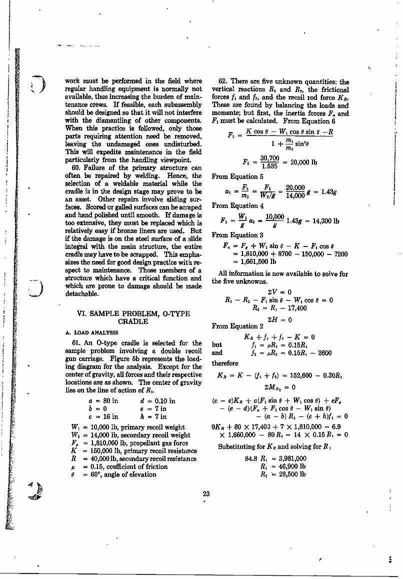
work must be performed in the field where 62. There are five unknown quantities: the) regular handling equipment is normally not vertical reactions R, and R, the frictionalavailable, thus increasing the burden of main- forces f, and ft, and. the recoil rod force Kv.tenance crews. If feasible, each subassembly These are found by balancing the loads andshould be designed so that it will not interfere moments; but first, the inertia forces F. andwith the dismantling of other components. F, must be calculated. From Equation 6When this practice is followed, only those K cos 0- W, cos 0 sin 0-Rparts requiring attention need be removed, = KIleaving the undamaged ones undisturbed. 1 + M sinThis will expedite maintenance in the fieldparticularly from the handling viewpoint. F2 = - 20,000 lb
60. Failure of the primary structure can 1.535 2often be repaired by welding. Hence, the From Equation 5selection of a weldable material while the F2 F2 20,000cradle is in the design stage may prove to be a2 = w =
- 1 4-ig = - -an asset. Other repairs involve sliding sur-faces. Scored or galled surfaces can be scraped From Equation 4and hand polished until smooth. If damage is WF = 10,000 1.43g = 14,300 lbtoo extensive, they must be replaced which is F = -9- a2 - grelatively easy if bronze liners are used. Butif the danage is on the steel surface of a Slide From Equation 3integral with the main structure, the entire F. = F + W, sin 0 - K - F, cos 0cradle may have to be scrapped. This empha- = 1,810,000 + 8700 - 150,000 - 7200sizes the need for good design practice with re- = 1,661,500 lbspect to maintenance. Those members of a All information is now available to solve forstructure which have a critical function and the five unknowns.which are prone to damage should be madedetachable. V= 0
R, - R 2 -F, sin 0- W, cos0 =0R2 = R, 17,400
VI. SAMPLE PROBLEM, O-TYPE1CR L = 0CRADLE From Equation 2
A. LOAD ANALYSIS KR- + f, + f. - K = 061. An O-type cradle is selected for the but 11 = ARi = 0.15R,
sample problem involving a double recoil and A2 = R2 = 0.15R, - 2600gun carriage. Figure 5b represents the load-ing diagram for the analysis, Except for the thereforecenter of gravity, all forces and their respective KR = K - (h' + f2) = 152,600 - 0.30R,locations are as shown. The center of gravitylies on the line of action of Rt.
a = 80 in d = 0.10 in (c - e)KR +a(F, sin 0 + W, cos 0) + eF,b =0 e = 7in - (e-d)(F. +Fcos0- Wsin0)c = 16 in h = 7in - (a- b) R- (e+h)fl = 0
W, = 10,000 lb, primary recoil weight 9KR + 80 x 17,400 + 7 X 1,810,000 - 6.9W2 = 14,000 lb, secondary recoil weight X 1,660,000 - 80 R - 14 X 0.15 R, = 0F, = 1,810,000 lb, propellant gas force Substituting for KR and solving for RK = 150,000 lb, primary recoil resistance
R = 40,000 lb, secondary recoil resistance 84.8 R, = 3,981,000= 0.15, ccefficient of friction R, = 46,900 lb
0 = 60, angle of elevation R2 29,500 lb
23
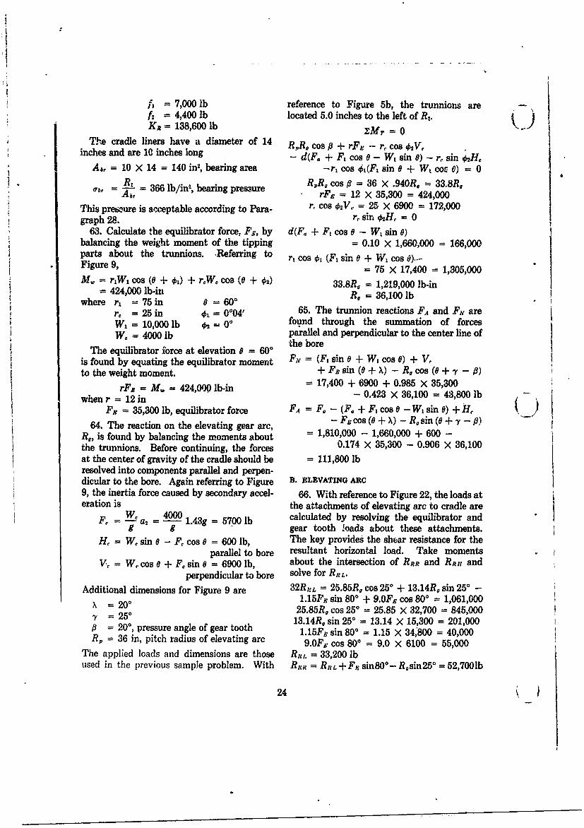
7,000 lb reference to Figure 5b, the trunnions are -f2 = 4,400 lb located 5.0 inches to the left of R2.Ki = 138,600 lb Mr
The cradle liners have a diameter of 14 RR. cos 0 + rFe -- r, cos 2V,inches and are 10 inches long - d(F. + F, cos 0 - W, sin 0) - r, sin o2 H,
A , 10 X 14 = 140 in2, bearing area -rt cos ot(Fl sin 0 + Wt cos 0) 0R. = _ 3 b - RR, cos f = 36 X .940R. = 33.8R.
Ob-r Abr rFa = 12 X 35,300 = 424,000
This presure is acceptable according to Para- r, cos . = 25 X 6900 172,000graph 28 r sin €H = 0
63. Calculate the equilibrator force, Fs, by d(F. + F1 cos 0 - Wt sin 0)balancing the weight moment of the tipping - 0.10 X 1,660,000 166,000parts about the trunnions. -Referring to r o ol (F, sin 0 + W, cos 6)-Figure 9, = 75 X 17,400 = 1,305,000Mf = rWj COS (0 + 1) + rW 0 COS (0 + 02) 33.8R, = 1,219,000 lb-in
= 424,000 lb-inwhere r, =75in 8 = 60'
= 25 in =04, 65. The trunnion reactions FA and Fv are= 10,000lb 2 = 00 found through the summation of forces
W/. = 4000 lb parallel and perpendicular to the center line of
The equilibrator force at elevation 0 = 600 the boreis found by equating the equilibrator moment FN = (F, sin 0 + W, cos 0) + V,to the weight moment. + F, sin (0 + X) - R, cos (0 + y' -
rFz = M = 424,O lb-in= 17,400 + 6900 + 0.985 X 35,300whenr = M2 in - 0.423 X 36,100 = 43,800 lb
Fx = 35,300 lb, equilibrator force FA = F, - (F. + F, cos 0 - W, sin 6) + H,64. The reaction on the elevating gear arc, - FE CO + X) - Rsin (0+,y -,0)
R,, is found by balancing the moments about = 1,810,000 - 1,660,000 + 600 -the trunnions. Before continuing, the forces 0.174 X 35,300 - 0.906 X 36,100at the center of gravity of the cradle should be = 111,800 lbresolved into components parallel and perpen-dicular to the bore. Again referring to Figure B. ELEVATING ARC9, the inertia force caused by secondary accel- 66. With reference to Figure 22, the loads ateration is the attachments of elevating arc to cradle are
F, =W. 4000 1.439 = 5700 lb calculated by resolving the equilibrator and= a 9 1--3- gear tooth loads about these attachments.
H, = W, sin 0 - F, cos 0 = 600 lb, The key provides the shear resistance for theparallel to bore resultant horizontal load. Take moments
V, = W, cos a + F, sin 0 = 6900 lb, about the intersection of RER and RR, andperpendicular to bore solve for RRL.
Additional dimensions for Figure 9 are 32Ru:L = 25.85R, cos 250 + 13.14R, sin 250 -
x =200 1.15F 8 sin 800 + 9.0FR cos 800 = 1,061,000)y = 20 25.85R, cos 250 = 25.85 X 32,700 = 845,000= 250 13.14R. sin 250 = 13.14 X 15,300 = 201,000
= 200, pressure angle of gear tooth 1.15Fs sin 80 ° = 1.15 X 34,800 = 40,000R, = 36 in, pitch radius of elevating arc 9.0F. cos 800 = 9.0 X 6100 = 55,000
The applied loads and dimensions are those RRL = 33,200 lbused in the previous sample problem. With Rtl = Re. +Fn sinSO0 - R~sin250 = 52,7001b
24
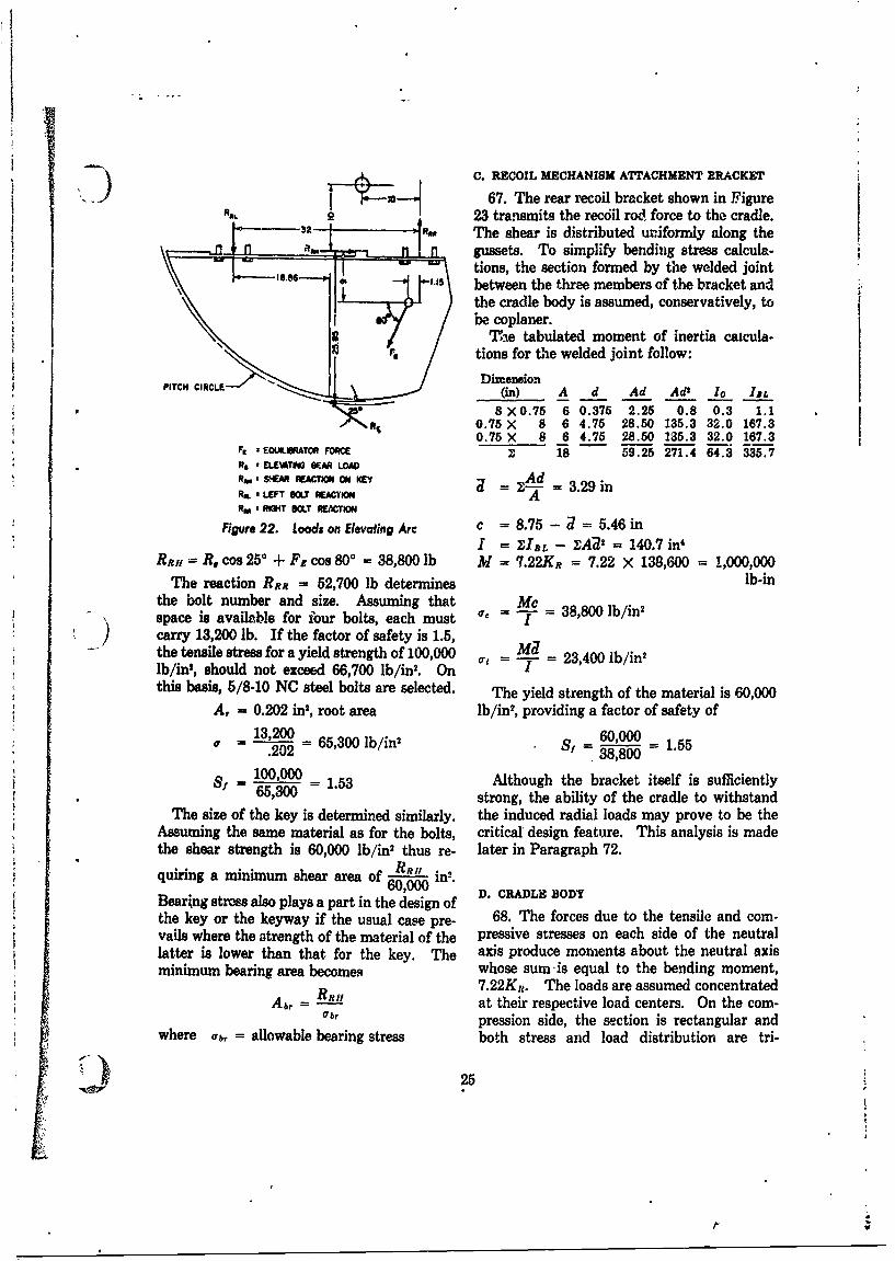
CRECOIL MECHANISM ATTACHMENT BRACKET
R 67. The rear recoil bracket shown in FigureAm 2 23 transmits the recdil rod force to the cradle.
-02 AM The shear is distributed uriformly along theL_ -- gussets. To simplify bending stress calcula-
tions, the section formed by the welded joint\, ----l.,----, ' between the three members of the bracket and
the cradle body is assumed, conservatively, tobe coplaner.
'The tabulated moment of inertia caicula-fit_ tions for the welded joint follow:
F2C c Dimensio.-ITCH CIRCE (in) A d Ad Ad' 1o I,8 X0.75 6 0.375 2.25 0.8 0.3 1.1
0.75 X 8 6 4.75 28.50 135.3 32.0 167.30.75 X 8 6 4.75 28.50 135.3 32.0 167.3
F a EQUILATOR FORCE 18 59.25 271.4 64.3 335.7R# * EUATMi "A LOADR, 2 &EMATI OIMON KEY
ifN'= - = 3.29 inR. a LEFT BOLT W.AC'MO ARm BOLT REAcn
Figure 22. Loads on Elevating Arc c = 8.75 - 2 5.46 inI = ZIL - ZA32 = 140.7 in'
RRH = R, cos 250 + Fs cos 800 = 38,800 lb P1 = 7.22KR = 7.22 X 138,600 = 1,000,000The reaction RRR = 52,700 lb determines lb-in
the bolt number and size. Assuming that Mcspace is available for four bolts, each must ¢° - " 38,800 lb/in2
S) carry 13,200 lb. If the factor of safety is 1.5,the tensile stress for a yield strength of 100,000 =t M2lb/in', should not exceed 66,700 lb/in' . On = 23,400 lb/in
this basis, 5/8-10 NC steel bolts are selected. The yield strength of the material is 60,000A, = 0.202 in2, root area lb/in2, providing a factor of safety of
13,200 = 65,3 lb/in2 60000= .202 - 530bi Sf 6= 0 = 1.55.202 38,800
s = 100,000 _ 1.53 Although the bracket itself is sufficiently65,300 strong, the ability of the cradle to withstand
The size of the key is determined similarly, the induced radial loads may prove to be theAssuming the same material as for the bolts, critical' design feature. This analysis is madethe shear strength is 60,000 lb/in2 thus re- later in Paragraph 72.
quiring a minimum shear area of A in.60,000 D. CRADLE BODYBearkng stres also plays a part in the design of
the key or the keyway if the usual case pre- 68. The forces due to the tensile and com-vails where the strength of the material of the pressive stresses on each side of the neutrallatter is lower than that for the key. The axis produce moments about the neutral axisminimum bearing area becomes whose sum- is equal to the bending moment,
7.22Kt. The loads are assumed concentratedAbr = - at their respective load centers. On the com-
wbl pression side, the section is rectangular andwhere Cb= allowable bearing stress both stress and load distribution are tri-
25
dor
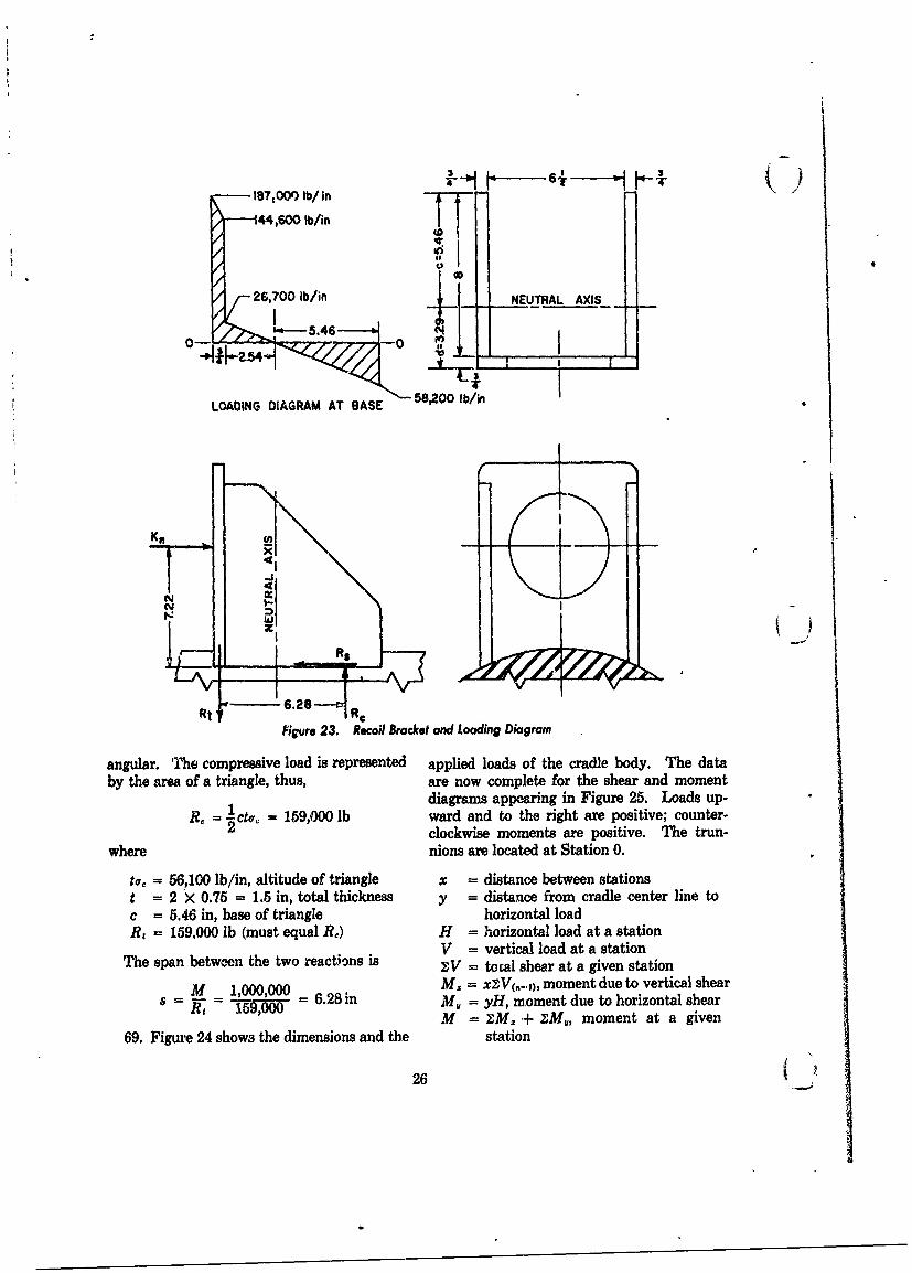
-18700 lb/ in
'44,600 lb/in TiI26,700 lb/in NEUTRAL AXIS
00
LOADING DIAGRAM AT 1ASE 58,200 b/n
Fiure 23. Recoil Bracket and Loading Dia grain
angular. The compressive load is represented applied loads of the cradle body. The data
by the area of a triangle, thus, are now complete for the shear and moment
= cte = 59,00 lbdiagrams appearing in Figure 25. Loads up-R =lct = 19,00 lbward and to the right are positive; counter-
clockwise moments are positive. The trun-
where nions are located at Station 0.
ta< 56,100 lb/in, altitude of triangle x = distance between stationst = 2 X 0.75 = 1.5 in, total thickness y =distance from cradle center line to
c .46 in, base of triangle horizontal load
R,=159,000 b (must equal RD) H = horizontal load at a stationV =vertical load at a station
The span between the two reactions is zIV = tocal shear at a given station
- M 6.2 inM, xZV(n-.,), moment due to vertical shearS M - - , ,00-,00= 6,8i My = yH, moment due to horizontal shear
R~ 15,000M = zM= + ZIMM, moment at a given
69. Figui'e 24 shows the dimensions and the station
26 (A
01I
1 --- 50 0 --- 4 25 O -0
Rt FA
RPL 32.0 t Ra
F , A)GAL AND NOWAL RE&TIONS ON TRUNNIONS
to .it FRICTIONAL FORCES ON FRONT AND REAR BEARINGS
H, & HORZONTAL AND VFERTI.AL FORCES OF CRDLE MASS
Ki RECOIL ROD FORCE
R6 .RT: VERTICAL LOADS DUE TO RECOIL ROD OFFSET
Rj,R 2t NOWAL LOADS ON FRONT AND REAR 9EARINGS
R,RintR HORIZONTAL AND VERTICAL LOADS OF ELEIrlNG ARC
Figure 24. Cradle Body Showing Applied Loads and Reacions
J) Shear and Moment Chart
Station x V XV H y M. M, M
75 0 -469 -469 70 7 0 49 49
25 50 -69 -538 6 0 2345 0 2394
22 3 332 -206 0 161 2555
12 10 0 -206 206 2961
12 -388 10 -388 2373
0 12 438 232 -1118 0 247 0 2620
-5 5 1885 2117 -116 2504-5 44 7 -31 2473-7.5 2.5 0 2117 -529 1944
-1 2.5 -527 1590 0 -529 1415-11.3 1.28 -1590 0 1386 8.78 -204 -1218 -7
Units of x and y are given in inches; V, ZV and H in 100 1b; M,, M, and M in 1000 lb-in.
To resume the analysis, assume the cylinder Mc 2,761,000 X 7.75 32 4to have an ID of 14.5 inches and an OD of T 7 - 66215.5 inches. The area is
IV 211,700 = 9,000 lb/in' (not critical)
A = 52 - -. 52) = 23.56 in 2
With the material having a yield strength ofThe moment of inertia is 60,000 lb/in, the bending stress shows a factor
of safety of almost 2, thus making a wall of94-I = -5 - .5') = 662 in' -1-inch thickness more than ample for the gen-
eral bending stresses. However, local stressesThe bending and shear stresses are present another problem and the wall must be
27255-012 (8040A) 0 - 67 - 3
If,
r
30 1
25 -ll
20
15
NJ
w 10
W
z*- S .
0:
a0 70 60 50 40 30 20 0 0 -t0 -20
STATION (in)
Figure 25. Shear and Moment Diagram, Cradle Body
ar
]r4II M R, M
CRADLE END SECTION A-A LOADING DIAGRAM
Figure 26. Isolated Ring Section of Cradle
reinforced where they appear. Rigidity is also 10 inches in length with flanges at each end asneeded to avoid local overloading and eventual shown in Figure 26. It carries a radial loadgalling of the bearing. Assume a ring at the Rt which is assumed to be uniformly dis-front end of the cradle body with a cross section tributed along the diameter of its centroidal
28 (
- From Equation 35BRACKET
-GUSSETS"..'R +1 (0 sin 0 + cos 0)
sin0 -0 cos
= 79,500 x .5 x 0.139 = 94,000 lb-inFrom Equation 36M,= WRm -
5 cos20)cs sos 0
(a) CHORDAL GUSSETS (b) TANGENTIAL GUSSETS - 1 - sin 0Figure 27. Recoil Bracket With Gusset Reinforcemen! = 79,500 > 8.5 × 0.177 = 119,700 lb-inaxis. According to Equation 209 of Refer- Fence 9* Equation 37
M Z- 1 Rr x46,900 X 8.09 = 47,400 lb-in ADZ= (0 sin 0 + cos 0)
11)where r. = r + .59 = 7.5 + 0.59 = 8.09 in, - 1 (sin20 + 1)the radius to the neutral axis ofthe section 79,500 x 614 0.177.Mc 29 X 101I XO0.105 1- in
From Equation 38where I = 1.58 in4 ! \2 4 -1)) 70 c 1.164 in AD,, = El I sin 0
70. The two types of gusset construction + (2 1 sdiscussed in Paragraph 51 are illustrated in y 2 / oFigure 27. Sketch (a) shows the gussets par- 79,500 614 0175.allel to chords of the ring. From Paragraph 79500 X 61468, the total load on two gussets is 29 x 10'I × (-0 "104 -
R, = 159,000 lb 71. Lower bending moments and deflections1 become available by having the gussets tangent
W = - R, = 79,500 lb, load per gusset to the ring as shown in Sketch (b) of Figure 27.Then, according to Paragraph 51 and Con-
This condition is represented by Condition dition (c) of Figure 21, the bending moments(d) of Paragraph 51 and Figure 21. The and deflections are relieved despite the largerdimensions from Figures 23 and 27 are gusset load which increases by the ratio of d/h,
the distance of the applied load to the pointsa=3.625 in 0 = 0.440 radianS= 3.25 in in0 = 0.440 radof attachment of the two types of gusset. Thush = 7.22 in sin 0 = 0.426
R. = 8.5 in cos 0 = 0.905 d 1.From Equation 34= x × " = 112,800 lb
where d = 10.23 inM.= WR.,[1(OsinO + cos 0)- 1 h = 7.22 in
= 79,500 X 8.5 X (-0.152) = Other dimensions of Sketch (b), Figure 27, are-102,800 lb-in
* Reprinted by permission from Advanced Mechanics a = 3.625 in sin 0 = 0.954of Materials by B. F. Seely and J. 0. Smith, Copyright R = 8.25 in cos 0 = 0.3001952, John Wiley & Sons, Inc. 0 = 1.268 radian
- 29
*1l
From Equation 30
M. = WR[.- sino]
= 112,800 X 8.25 X (-0.074) -68,800 lb-in
From Equation 31
my4( = - (R_ 1) cos 0 + ~-sin 8]
= 112,800 X 8.25 x 0.038 = 35,400 lb-in
From Equation 32
wR. [20D= I - sin 0+ ;Cos 6
112,800 X 562 0.096.= 2 X 0' X 0.044 = i'n-- 29 x10 I
From Equation 33
112,800 X 562 0.081.= x i10i (-0.037)= -- in
72. A compaison of the required wall thick- 8ness for the two conditions shows that the Ge - = 38,400 lb/in2, equivalent stresstangential gussets are preferred. For the S - 60,000 1.56, factor ofchordal gussets, the maximum equivalent as T_00 safety. (stress is at 0 (see Sketch (a) of Figure 27). For the tangential gussets, the maximumThe dimensions of the cradle wall at this loca- equivalent stress is located on the x-axis wheretion are the general bending stress is zero. Thus
b = 5.46 in, assumed ring width (Figure 23) 1c = 8.78 in, chordal distance to gusset Z = bt2 2.05 in "
R, = 7.5 in, inside radius vR. = 9.5 in, outside radius o,= -o =T = 33,500 lb/in2
t = 2.0 in, wall thicknessM, = 119,700 lb-in (see Paragraph 70) where
M1 =-68,800 lb-in (see Paragraph 63)Z bt2 = 3.64 in 3, section modulus b = 5.46 in, assumed ring width (Figure 23)
t = 1.5 in, wall.thicknessO. = - MO/Z = -32,800 lb/in2 Ro.= 9.0 in, outer radius of cradle wall
I = (R - RID) = 3910 in The wall thickness of 1.5 inches is preferredover that of 2.0 inches, thus demonstrating the
The general bending moment is taken from advantage of tangential gussets.the Shear and Moment Chart (Paragraph 69). 73. The bearing pressure induced by theAt Station 5 gusset load is found according to the method
M = 2,473,000 lb-in discussed in Paragraph 52. By equating theexpressions for AD, 'in Equation 39 and Para-
S 43910 - 5600 lb/in2 graph 71, we have(-.6)wR- WR-3(007
From Equations 15a and 15b (-0.467) E W -I7
30
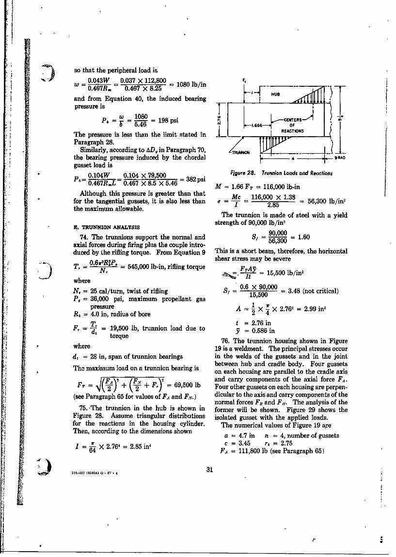
) so that the peripheral load is
0.043W 0.037 x 112,800 = 1080 lb/in FTw =06.46-7R. 0.467 X 8.25 ,sand from Equation 40, the induced bearing
* pressure is_W 1080 _ 198-psP b =- 198 psi 11 .6 C TR-lI
1.666 OF
The pressure is less than the limit stated in , REACTIONSParagraph 28.
Similarly, according to AD,, in Paragraph 70, ___
the bearing pressure induced by the chordal 4 " 9 RAO
gusset load is0.104W 0.104 X 79,500 = Fjgure 28. Trunnion Loads and Reactions
P6= 0.467RL = 0.467 X 8.5 X 5.46 = 382 psiM = 1.66 FT = 116,000 lb-in
Although this pressure is greater than that Mc 116,000 x 1.38for the tangential gussets, it is also less than 2 = = 2.85 = 56,300 lb/in2
the maximum allowable.The trunnion is made of steel with a yield
B. TRUNNION A S strength of 90,000 lb/in
74. The trunnions support the normal and Sf = 90, = 1.60axial forces during firing plus the couple intro- 56,300
duced by the rifling torque. From Equation 9 This is a short beam, therefore, the horizontalshear stress may be severeT = 0.61Rk, = 545,000 lb-in, rifling torque F___
N, "T - 15,500 lb/in2
where0.6 X 90,000=3.8(tcria)
N, = 25 cal/turn, twist of rifling S 1 ,500 3.48 (not critical)P, = 36,000 psi, maximum propellant gas
pressure A 1 X 2.762 = 2.99 in2
Rb = 4.0 in, radius of bore 2 4T, t =2.76 in
F, - = 19,500 lb, trunnion load due to = 0.56 ind,5i 0.586 intorque 76. The trunnion housing shown in Figure
where 19 is a weldment. The principal stresses occur
d, = 28 in, span of trunnion bearings in the welds of the gussets and in the jointbetween hub and cradle body. Four gussetsTho maximum load on a trunnion bearing ison each housing are parallel to the cradle axis
IIF\ ('p \2 and carry components of the axial force FA.FT = ,L)' + (2 + F) = 69,500 lb Four other gussets on each housing are perpen-
(see Paragraph 65 for values of FA and Fv.) dicular to the axis and carry components of thenormal forces Fit and F,. The analysis of the
75. The trunnion in the hub is shown in former will be shown. Figure 29 shows theFigure 28. Assume triangular distributions isolated gusset with the applied loads.for the reactions in the housing cylinder. The numerical values of Figure 19 AreThen, according to the dimensions shown a = 4.7 in n = 4, number of gussets
c = 3.45 rh = 2.75-1 =X 2.761 =2.85 in,64 F,, = 111,800 lb (see Paragraph 65)
255-012 (8040A) 0 - 67 - 4 31
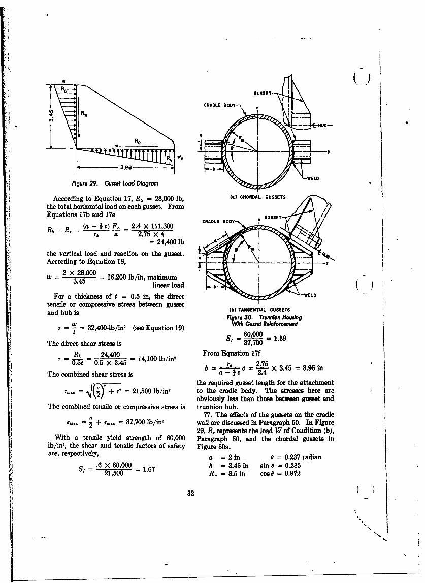
IW()
GUSSET-
CRADLE BODY'-,
Re
• 5.96 1
Figure 29. Gusset Load Diagram
According to Equation 17, Ra = 28,000 1b, () CHORDAL GUSSETS
the total horizontal load on each gusset. FromEquations 17b and .17e GUSSET
Rh R = (a - I c) FA 2.4 X 111,800rA A 2.75 X4
= 24,400 lb
the vertical load and reaction on the gusset.According to Equation 18, -
=w 2x28,000 16,200 lb/in, maximum("' = .45 =linear load
For a thickness of t = 0.5 in, the direct WELDtensile or compressive stress between gusset M TANGENTIAL GUSSETSand hub is )TNEITLGUST
Figure 30. TNrnnion Housing(e With Gusset Reinforcementa -7 = 32,400-.b/in (see Equation 19)
S1=60,000 =15The direct shear stressi =i = 1.59
RA 24,400 From Equation 17f0. c 0.5 X 345 14,100 lb/in? rA 2.75
b c =1-75X 3.45 = 3.96 inThe combined shear stress is a- c 2.4
Ithe required gusset length for the attachment1x -4 1 + r= 21,500 lb/in' to the cradle bcdy. The stresses here are
Thm obviously less than those between gusset andThe combined tensile or compressive stress is trunnion hub.
77. The effects of the gussets on the cradle+ 37,700 lb/in2 wall are discussed in Paragraph 50. In Figure
29, R, represents the load W of Coidition (b),With a tensile yield strength of 60,000 Paragraph 50, and the chordal gussets in
lb/in', the shear and tensile factors of safety Figure 30a.are, respectively, a = 2 in 0 = 0.237 radian
Is = .6 X 60,000 = 1.67 h = 3.45 in sin e = 0.23521,500 R, = 8.5 in cos 0 = 0.972
32( )
I S
'S"S.
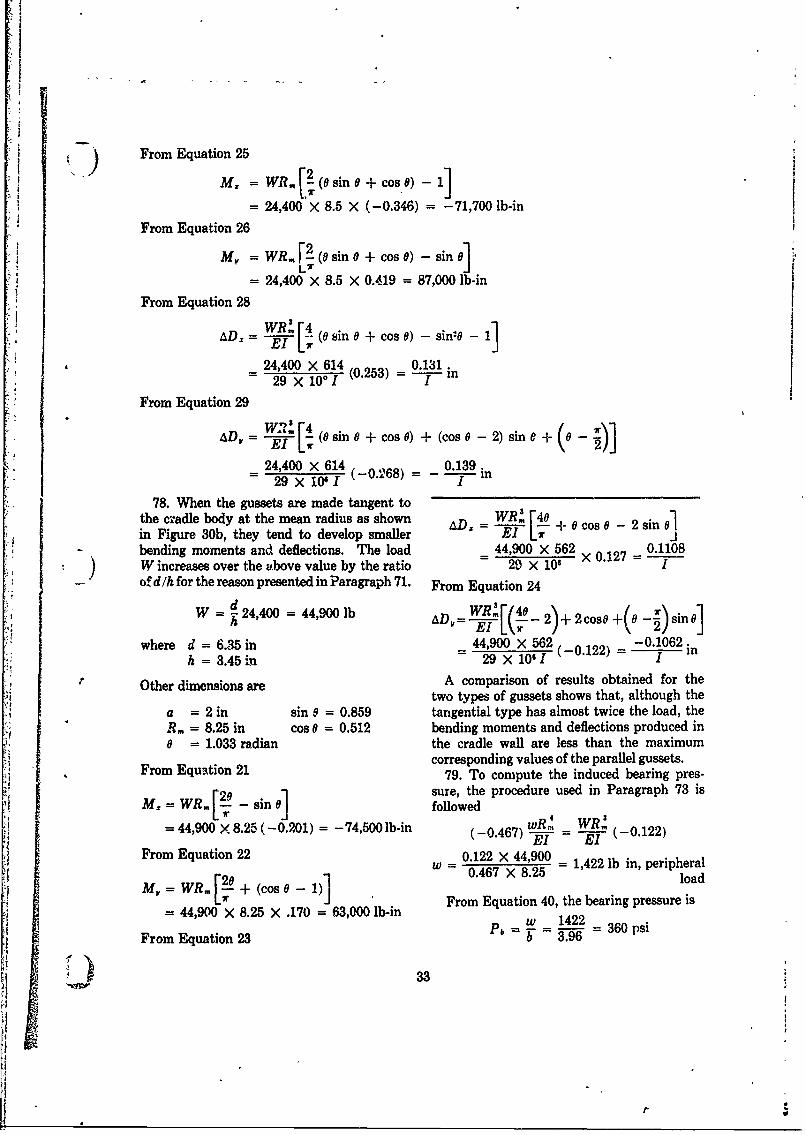
)/ From Equation 25
= 24,400 X 8.5 X (-0.346) = -71,700 lb-in
From Equation 26
M = WR. r2 (8 sin 0 + cos 8) - sine]LT
= 24,400 X 8.5 X 0.419 = 87,000 lb-in
From Equation 28
WR.L iAD.- E (6sin0 + cos0) - sin'- - 1
24,400 x 614 0.131.29 X 106i (0.253) in
From Equation 29 (_ ).AD, = E [ (0sin + cos0) + (coso - 2) sinC + 0-
24,400 x 614 0.139.29 X 1061 (-0.268) = --- n
78. When the gussets are made tangent tothe cradle body at the mean radius as shown WR! [40 sin Figure 30b, they tend to develop smaller lT -{ ibending moments and deflections. The load = 44,900 X 562 × 0.127 = 0.11081 W increases over the above value by the ratio 29 X 106 I
- of dlh for the reason presented in Paragraph 71. From Equation 24
W 24,400 = 44,900 lb WD '[(4sh ~E ADAIr7 2 o2)s
where d = 6.35 in 44,900 X 562 -0.1062.h = 3.45 in - 29 X 10'I (-0122) = i
Other dimensions r A comparison of results obtained for thetwo types of gussets shows that, although the
a = 2 in sin0 = 0.859 tangential type has almost twice the load, theR. = 8.25 in cos 0 = 0.512 bending moments and deflections produced in0 = 1.033 radian the cradle wall are less than the maximum
corresponding values of the parallel gussets.79. To compute the induced bearing pres-
F e 1 sure, the procedure used in Paragraph 73 isMz= WR,, .- - sin 0 followed wR,w44,900 X 8.25 (-0.201) = -74,500 lb-in (-0.467) w--R (-0.122)
From Equation 22 0.122 X 44,900w - 0.467 - 1,422 lb in, peripheral
M =WRi2(o9)M( -)From Equation 40, the bearing pressure is
= 44,900 x 8.25 X .170 = 63,000 lb-inw 1422
From Equation 23 P6 b- = 9 360 psi
1 33d ,
JV
where b 3.96 in (see Figure 29, Paragraph therefore i76). KR = K - (f + fI) = 149,200 - 0.30R -
The pressure meets the conditions stated in MR. = 0Paragraph 28. (c-e)KR + eF, - (e-d) (F. - W sin 0)
80. The critical compressive stress obtained - aW cos a - (e-h)ft - (a-b)R = 0of the gussets buckling is extremely remote. (e-h)f = 1.0(0.15R) = 0.15&
E K 540,000 lb 'in' (c-e)KR = 8(149,200- 0.30 RI)= K.1 = 1,194,000 - 2.40R1
where a = 3.96 in K. = 1.06 eF, = 8 X 1,810,000 = 14,480,000b = 3.45 in t = 0.5in (e-d)(F. - Wsin0) = 7.9 X 1,660,000E = 29 x 10, lb /in- P =(6.3 = 13,114,000
aW cos0 = 80 X 5000 = 400,000
62.55Rt = 2,160,000VIL. SAMPLE PROBLEM, U-TYPE R, = 34,500 lb
CRADLE R2 = 39,500 lbA. LOAD ANALYSIS A = 5200 lb
C 81. A U-type cradle is selected for 'the f2 = 5900 lb
sample problem involving a single recoil gun KR = 138,900 lbcarriage. Figure 5a represents the loadingdiagram for the analysis 1. Rails and Slides
a = 80 in i = 0.1 in 83. The reactions Rt and R2 are carriedb = 20 in e = 8 in equally by two rails, each 90 inches long.c = 16 in h = 7 in These reactions have an assumed triangular
W, = 10,000 Ib, weight of recoiling parts distribution, but the reaction due to riflingF, = 1,810,000 lb, propellant gas force torque is distributed uniformly. The rails are (K = 150,000 lb, total recoil resistance 3.0 inches wide and their center-to-center
= 0.15, coefficient of friction distance is 17 inches. From Paragraph 74,0 = 60*, angle of elevation T, = 545,000 lb-in
82. The values of R1, R2, ft, f2 and KR are F, = d 1 32,000 lbunknown. These are found by balancing the d 7loads and moments. F, 3From Equation 3, since F, is zero, the inertia 90
force is Let R2 represent the triangular portion ofF. = F, + W, sine - K R2(see Figure 12).
= 1,810,000 + 8700 - 150,000= 1,668,700 lb 1 w2 = R2
XV = 0R, -R 2 +Wcos 0 = 39,500 = 8751b/inR2 =R + 5000 45
H o w = w2 + w, = 12301b/inFrom Equation 2 The maximum bearing pressure becomes
K, + f + f 2 -K 0 : = 410 lb/in'but from Equations 1 and lU 3
h = uR, = 0.15R, This pressure is acceptable according tof2 = A2 = 0.15 (R + 5000) Paragraph 28.
34
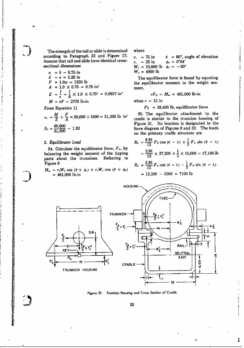
The strength of the rail or slide is determined whereaccording to Paragraph 32 and Figure 17, r, = 75 in 0 = 60, angle of elevationAssume that rail and slide have identical cross- r, = 25 in ot = 0004'sectional dimensions W 000l 2=-0
a = b = 0.75 in W, = 4000 lbd = e = 2.25 in The equilibrator force is found by equatingF = 1.0w = 1230 lb the equilibrator moment to the weight mo-A = 1.0 X 0.75 = 0.75 in2 ment.
Sc 6 1.0 x 0.752 =0.0937 in' rF,, = M. = 461,000 lb-in
M = eF = 2770 lb-in when r = 12 in
From Equation 11 F;: = 38,400 lb, equilibrator force
M F 85. The equilibrator attachment to theT= - + - = 29,600 + 1600 = 31,200 lb in cradle is similar to the trunnion housing of
Figure 31. Its location is designated in theS' = 31,00=- 1.92 force diagram of Figures 8 and 32. The loads
'31,200 on the primary cradle structure are
2. Equilibrator Load R, = Ff cos (0 - 1) + 1 Fn sin (0 - X)12 2~o( )+Fsn(
84. Calculate the equilibrator force, Fj,, bybalancing the weight moment of the tipping -X 37,200 + X 10,000 = 17,100 lbparts about the trunnions. Referring to 12 2
Figure 8 1 F-, cos (0 - 2 Fp. sin (0 - X)M = r1W cos (6 + o,) + rW, cos (0 + 52)1) = 461,000 lb-in = 12,100 - 5000 = 7100 lb
HOUSING
FAFi 9 r_
"' 18
TRUNNION HOUSING , J J
FN +B Thi 4
Figure 31. Trunnion Housing and Cross Section of Cradle
353!
V
LN + RAI
" :;F'28 4
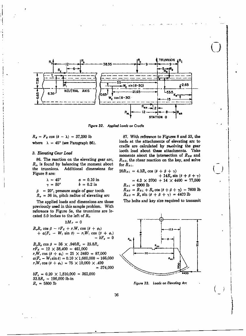
R tTRUNNIN I Rt
'i) - . NEUTRAL A-XIS -- 5W'i(- 0 f
R 12 14 ~-) 38-.--5 ,9 9
55-1
12 6O (6Ri
Figure 32. Applied Loads on Cradle
0= F cos (8 - X) = 37,200 lb 87. With reference to Figures 8 and 33, the
*where x = 450 (se Paragraph 86). loads at the attachments of elevating arc tocradle are calculated by redolving the gear
3. Eevatng Cear oad oth load about these attachments. Take3. Eevatng Gar ~moments about the intersection of BR and
86. The reaction on the elevating gear arc, RRI,, the shear reaction on the key, and solveR0, is found by balancing the moment about for R,t ..
the15
tetrunnions. Additional dimensions for 2OR,,,. = 4.3R. co (8 +/ + 7) ()Figure 8 are: + A4Rlisin (8 + + Ca)
S=5° a =0.10in = 4.3 X3700 +14 X4400= 77,5007 =50 ° b =0.2 in R,L =3900 lb
= 200, pressure angle of gear tooth R t RRL + r cos 8 + + ) = 7600 lbre = 36 in, pitch radius of elevating arc Rtoi =R sin (8 + + .) 44C0 lb
The applied loads and dimensions are those The bolts and key size required to transmitpreviously used in this sample problem. Withreference to Figure 5a, the trunnions are lo-cated 5.0 inches to the left of u. oR
x M7 = 0R R n cos s - rF i + rfW cos (8 + +y))
+ a(F - W sin +) - r1W4 cos (0 + ) _yR R X cos i = 36 X .940R 33.8RrF ' 00 00 = 461,000 X 3_ 0 ,
rW, cos (8 + €2) = 25 X 3460 = 87,000 o.a(F0 - Wsin8) = 0.10 )'1,660,000 = 166,000 ,r1W1 cos (0 + 4) = 75 X 10,000 X .499"\
= 374,000bFb = 0.20 X 1,810,000 = 362,000 4400
33.8R 20 = 196,000 lb-inR = 5800 eb Figure 33. Loads on Elevating Arc
36
The ppled oadsanddimnsios ae tose The olt an keysiz reuire totrasmi
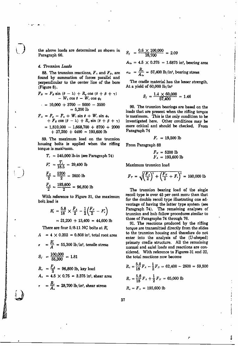
1) the above loads are determined as shown in S/ 0.6 X 100,000Paragraph 66. = 28,700 = 2.09
4. Trunnion Loads Ab, = 4.5 X 0.375 = 1.6875 in2, bearing area
88. The trunnion reactions, FA and FN, are , = - = 57,400 lb/in2, bearing stressfound by summation of forces parallel andperpendicular to the center line of the bore The cradle material has the lesser strength.(Figure 8). At a yield of 60,000 lb/in2
FN = Fgsin (0 - X) + R, cos (0 + 0 + ) 1.4 x 60,000 1.46- W cos 0 - W, cos 02 Sf = 57,400
= 10,000 + 3700 - 5000 - 3500 90. The trunnion bearings are based on the= 5,200 lb loads that are present when the rifling torque
FA = F, - F. + W, sin 0 + W sin .2 is maximum. This is the only condition to be+ Fg cos (0 - X) + R, sin (0 + 0 + ,Y) investigated here. Other conditions may be
= 1,810,000 - 1,668,700 + 8700 + 2000 more critical and should be checked. From+ 37,200 + 4400 = 193,600 lb Paragraph 74
89. The maximum load on the trunnion F, = 19,500 lbhousing bolts is applied when the rifling From Paragraph 88torque is maximum. FN =5200 lb
T, = 545,000 lb-in (see Paragraph 74) FA = 193,600 lbF,' = l = 29,400 lb Maximum trunnion load
18.5) FN2- = 2600 lb Fr = -+- + F = 100,000 lb
2 2 = 2 2+FA- 19,0 = 96,800 lbFA 1 0- 9The trunnion bearing load of the single
With reference to Figure 31, the maximum recoil type is over 45 per cent morm than that
bolt load is for the double recoil type illustrating one ad-vantage of having the latter type system (see
5.8 FA 1 F , Paragraph 74). The remaining analyses ofR X 18 2 2 \ T - ) trunnion and hub follow procedures similar to= 31,200 + 13,400 = 44,600 lb those of Paragraphs 74 through 76.
91. The reactions produced by the riflingThere are four 5/8-11 NC bolts at R; torque are transmitted directly from the slides
A 4 X 0.202 = 0.808 in' , total root area to the trunnion housing and therefore do notenter into the analysis of the (U-shaped)
R; primary cradle structure. All the remainingA - 55,300 lb/in2 , tensile stress normal and axial loads and reactions are con-
100,000 sidered. With reference to Figures 31 and 32,S -=000 = 1.81 the total reactions now become55,300 =
FA R 8 F.A - 62,400 - 2600 59,800R -- 2 = 96,800 lb, key load 18 A
A. = 4.6 X 0.75 = 3.375 in2, shear area R, = 1 FA+ 1 F, = 65,000 lb
. =28,700 lb/in2, shear stress 18 FA +2A. R. = F1 193,600 lb
37
V
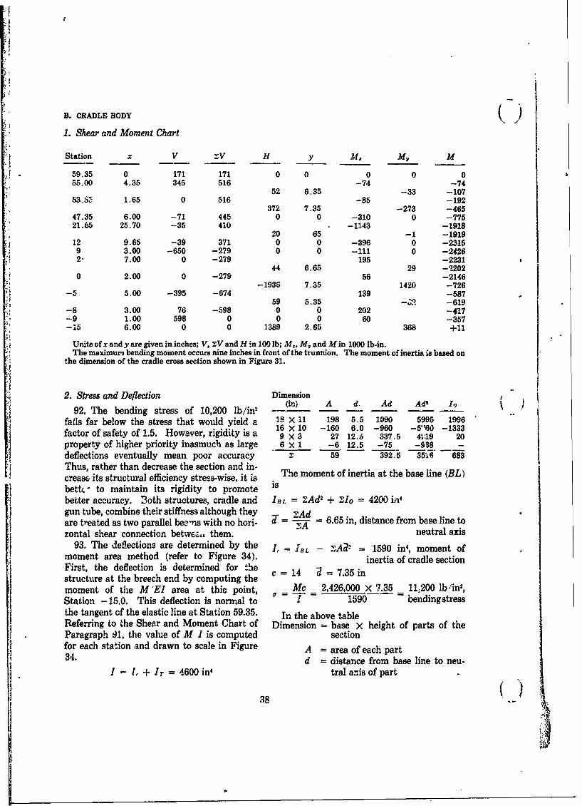
B. CRADLE BODY (1. Shear and Moment Chart
Station x V X V H y M, M, M
59.35 0 171 171 0 0 0 0 055.00 4.35 345 516 -74 -74
52 6.35 -33 -10753.&5 1.65 0 516 -85 -192
372 7.35 -273 -46547.35 6.00 -71 445 0 0 -310 0 -77521.65 25.70 -35 410 -1143 -1918
20 65 - 1 -191912 9.65 -39 371 0 0 -396 0 -23159 3.00 -650 -279 0 0 -111 0 -24262" 7.00 0 -279 195 -2231
44 6.65 29 -22020 2.00 0 -279 56 -2146-1938 7.35 1420 -726
-5 5.00 -395 -674 139 -58759 5.35 -;R -619
-8 3.00 76 -598 0 0 202 -417-9 1.00 598 0 0 0 60 -357-15 6.00 0 0 1389 2.65 368 +11
Units of x and y are given in inches; V, XV and H in 100 lb; M, M, and M in 1000 lb-in.The maximum bending moment occurs nine inches in front of the trunnion. The moment of inertia is based on
the dimension of the cradle cross section shown in Figure 31.
2. Stress and Deflection Dimension
92. The bending stress of 10,200 lb/in2 k A d. Ad Ad I,)
falls far below the stress that would yield a 18 x 11 198 5.5 1090 5995 199616 X 10 -160 6.0 -960 -5160 -1333
factor of safety of 1.5. Howaver, rigidity is a 9 X 3 27 12.6 337.5 4,19 20property of higher priority inasmuch as large 6 X 1 -6 12.5 -75 -938 -
deflections eventually mean poor accuracy 2 59 392.5 3516 683Thus, rather than decrease the section and in-crease its structural efficiency stress-wise, it is The moment of inertia at the base line (EL)betk' to maintain its rigidity to promote is
better accuracy. 3oth structures, cradle and IBL = ZAd 2 + 2Io = 4200 in'gun tube, combine their stiffness although they - "Adare treated as two parallel bee-ns with no hori- d = 6.65 in, distance from base line tozontal shear connection betwF-,, them. neutral axis
93. The deflections are determined by the I =IBL - _A2 = 1590 in', moment ofmoment area method (refer to Figure 34). inertia of cradle sectionFirst, the deflection is determined for thestructure at the breech end by computing the
moment of the M 'EI area at this point, Mc 2,426,000 X 7.35 11:200 lb /in2,Station -15.0. This deflection is normal to 0' 1 1590 bendingstressthe tangent of the elastic line at Station 59.35. In the above tableReferring to %he Shear and Moment Chart of Dimension = base X height of parts of theParagraph 91, the value of M I is computed sectionfor each station and drawn to scale in Figure A - area of each part34. d = distance from base line to neu-
I -1 , + Ir = 4600 in' tral anis of part
38
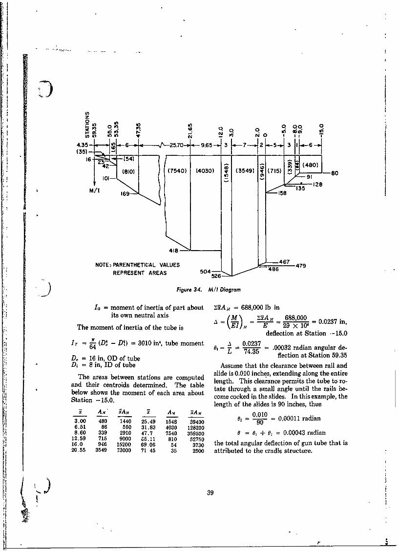
z{
2 in* In,in 0. 0 009 0
9.. to in In It o 0 r4.35 4---.--4. 6 5.7O-449.65--, 3 [ -7--,2K53.1.-(35) .. . 1, __-
16-16442 - - ~ (480)
I0 (80)j0
NOTE : PARENTHETICAL VALUES -4 I.6 7 9
REPRESENT AREAS 5( 04-48
()0Figure 34. M I Diagram
*Io = moment of inertia of part about SA . = 688,000 lb inits own neutral axis (M\' '2 688,000
The moment of inertia of the tube is E-\EI,1 . E =29 < 106=.23 ndeflection at Station -15.0
r -' D - DI,) = 3010 in', tube moment -. 0.0237 -002rda nua eD / = 16 in, OD of tube flection at Station 59.35
*D, = 8 in, ID of tube Assume that the clearance between rail andThe rea beteenstatonsare ompted slide is 0.010 inches, extending along the entire
and their centroids determined. The table lnt.Ti laac emt h uet obelo shws he omet ofeac ara aout tate through a small angle until the rails be-
Staton -15.0.moet feaharaabu come cocked in the slides. In this example, theStaton -5.0.length of the slides is 90 inches, thus
x AM A. x Av A. 0.010 0001rda3.00 480 1440 25.49 1548 39400 : 9 0 .001rda6.51 86 560 31.83 4030 1282008.60 339 2910 47.7 7540 359500 0 = o| + 0:, = 0.00043 radian
12.59 715 9000 65.1!1 810 5275016.0 946 15200 69.06 54 3730 the total angular deflection of gun tube that is20.55 3549 73000 71 45 35 2500 attributed to the cradl6 structure.
" 39:418
GLOSSARY
breechblock. The part of a gun, especially a support to the recoiling parts during te re-cannon, which closes the breech. coil cycle.
carriage, gun. Mobile or fixed support for a guide, continuous. Guide made of one con-cannon. tinuous member.
carriage, top. Primary supporting structure guide, discontinuous. Guide made of sev-of a weapon. It supports the tipping parts eral short lengths spaced at regular inter-and moves with the cradle in traverse. In vals. See clip.double recoil systems it comprises the bulk lug, gun. An appendage of the breech ringof the secondary recoiling mass. for attaching the recoil mechanism.
clip. A component of a discontinuous guide. moment, tipping. The couple created bycounterrecoil. Forward movement of a gun the firing forces and the inertia of the tip-
returning to firing position (battery) after ping parts.recoil. moment, upsetting. The couple created by
cradle. The nonrecoiling structure of a the firing forces and the inertia of the re-weapon which houses the recoiling parts and coiling parts.rotates about the trunnions to elevate the moment, weight. The moment about theweapon. cradle trunnions produced by the weight of
cradle, 0-type. A cradle which supports the tipping parts.the gun tube within a cylindrical housing. mount, gun. An item designed to support a
cradle, U-type. A cradle which supports the gun.gun tube on longitudinal guides. rail. A supporting member of the recoiling (
elevating arc. A gear segment rigidly at- parts that slides in a guide.tached to the tipping parts and serving as rail, continuous. Rail made of one member.the terminal member in the gear train of the rail, dikontinuous. Rail made of severalelevating mechanism. short lengths spaced at regular intervals.
elevating mechanism. Mechanism on a recoil. The rearward movement of a gungun carriage or launcher by which the tip- caused by the propellant gas force.ping parts are elevated or depressed. recoil cylinder. The cylinder that houses the
elevation. Angle of e"-'.ntion; the process recoil brake.of changing the angle of elevation, recoil mechanism. The unit that absorbs
equilibrator. The force-producing mechan- some of the energy of recoil and stores theism whose function is to provide a moment rest for returning the recoiling parts toabout the cradle trunnions equal and op- battery.posite to that caused by the muzzle prepon recoil mechanism, concentric. A recoilderance of the tipping parts, thereby re- mechanism that is assembled concentricallyducing the effort required to elevate, on the gun tube.
force, equilibrator. The force generated by recoil system, double. A system in whichthe equilibrator, the gun recoils on the top carriage and the
force, propellant gas. The force due to the top carriage recoils on the bottom carriage.propellant gases that drives the gun rear- recoil system, single. A system that hasward into recoil. only the gun tube and its components as
force, recoil. The resistance provided to the recoiling parts. 'recoiling parts. recoiling parts. Those parts of a weapon
guide. Channel-shaped structure of the that move in recoil.cradle which provides sliding surface and recoiling parts, primary. In a double recoil
\40
system, the recoiling parts equivalent to weapon which moves in elevation or de--those of a single recoil system, i.e., tube, pression about the trunnions.
breech assembly, guides or sleigh, and those torque, rifling. The reaction on the gunparts of the recoil mechanism which move tube of the angular accelerating forces on thewith the tube. projectile.
recoiling parts, secondary. In a double traversing gear. A gear rigidly attached torecoil system, the cradle, those parts of the the traversing parts and meshed with theprimary recoil mechanism which do not traversing mechanism.move with the tube, the top carriage, and all trunnion. The cylindrical structural corn-those parts attached to it. ponent of the cradle which serves as the
recuperat6r. The equipment that stores pivot for the tipping parts and which trans-some of the energy of recoil for counterre- mits the recoil forcee to the top carriage.coil. trunnion bearing. The bearing that sup-
ring, breech. Breechblock housing, screwed ports the trunnion.or shrunk on the rear of a cannon. tube, gun. A hollow cylinder, usually of
sleigh. The housing of a gun tube that slides steel, in which a round of ammunition isin a U-type cradle during the recoil cycle, fired and directed.
slide. Same as rail. tube whip. The flexing of the gun tube duetipping parts. The assembled structure of a to accelerating forces normal to the tube axis.
i) - 41
r I

REFERENCES
1. ORDP 20-340, Ordnance Engineering Design Chemistry and Physics, 40th Ed., Chemical Rub-Handbook, Carriages and Mounts Series, Car- ber Publishing Company, Cleveland, 1958-1959.riages and Mounts, General. 6. Hoffman and Sachs, Introduction to the Theory of
2. ORDP 20-342, Ordnance Engineering Design Plasticity for Engineers, McGraw-Hill Book Co.,Handbook, Carriages and Mounts Series, Recoil Inc., New York, 1953.Systems. 7. R. J. Roark, Formulas for Stress and Strain, 3rd
3. ORDP 20-345, Ordnance Engineering Design Ed., McGraw-Hill Book Co., Inc., New York, 1954.Handbook, Carriages and Mounts Series, Equi. 8. ORDF 20-134, Ordnance Engineering Designlibrctors. Handbook, Maintenance Engineering Principles
4. A Report on the Analysis of Gun Carriage, 175mm, for Design Engineers.T76, The Franklin Institute, Final Report 9. F. B. Seely and J.*O. Smith, Advanced MechanicsF-2240, Part I. of Materials, John Wiley and Sons, Inc., New
5. Charles D. Hodgman, et al, Ed., Ha.'dbook of York, 1952.
42( )

INDEX
Cleaning, 22 Maintenance, 22
Cradle Manufacture, 22
body, 25, 37 see also Structure Materials, 22
function of, 10-type, 3, 10, 3 0-type cradle, 3,10, 23
type, 2U-type, 2,a10, 34 Rails, 13, 34
Recoil
Design attachment bracket, 20, 25
of trunnion, 16, 31 force, 5
practice, 21 mechanism, 1, 5
problem, 23, 24 References, 42
procedure, 5 Rifling torque, 10, 31
Elevating arc, 2, 7, 24, 36 Sae role t 23 , Equilibrator, 2, 7 Shear and moment chart, 26, 37
Equilibrator force, 7, 24, 35 Sleigh, 2, 13Sliding surfaces, 11, 15, 34Strength requirement, 17
Friction effect, 15 Structure, 5, 21 see also Cradle bady
Glossary, 40 Symbols, list, vi
Gussets, 18, 29, 32, 34 Temperature effect, 4Trunnion, 2, 16, 18, 24, 31, 37
Illustrations, list, v analysis, 31Inspection, 22 design, 16, 31
hub, 18Keys, 24 load, 16, 24, 57
location, 16
Load lnalysis, 23, 34Lubrication, 22 U-type cradle, 2, 10, 34
43
U. S, GOVERNMENT PRINTING OF9I CE: 1967 0 - 255-012 (8040A)
r
(