Embed Size (px)
Citation preview
1
ARNG WARRIOR TRAINING CENTER
PATHFINDER COURSE FORT BENNING, GEORGIA 31905
ATSH-TPP-HQ 071A0220 01 NOVEMBER 2010
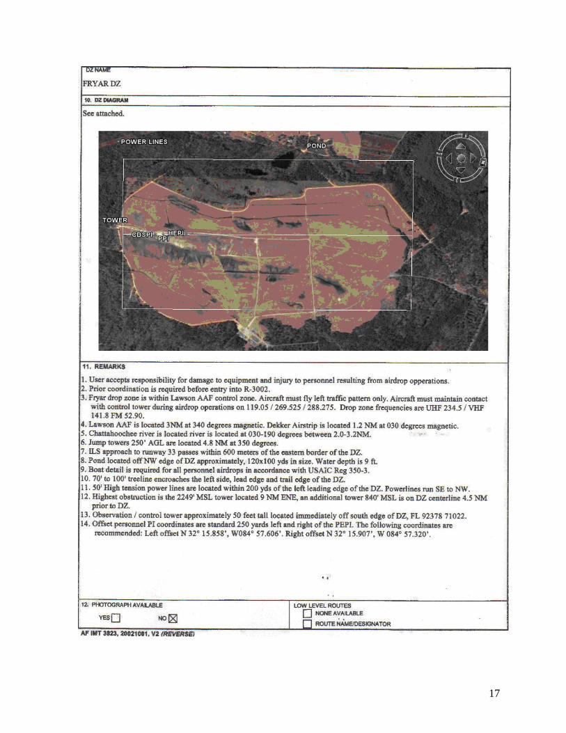
DZ SUMMARY SHEET:
INSTRUCTIONAL INTENT: To enable the Pathfinder student to plan for and operate day night airborne operations. The student will learn how to plan, organize and operate CARP, VIRS and GMRS Drop Zones, Coordinate with Army/Air Force pilots and Ground Unit Commander; and the duties and responsibilities of the Drop Zone Control Team.
Definition of a drop zone A designated area where personnel and/or equipment are delivered by means of a parachute or in the case of certain items, by free drop. The ground unit commander is responsible for designating the drop zone location. All drop zones must be on government owned for government leased land with a current survey or tactical assessment.
Test Section 1 The Eight Selection Factors CARP 2-5
Test Section 2 CARP Drop Zone Sizes 6-17
Test Section 3 Duties and Responsibilities of the DZSTL Drop Zone Surveys 18-25
Test Section 4 Army V.I.R.S. 26-32 Army G.M.R.S. 32-37
Test Section 5 Drop Zone Formulas 38-40 Test Section 6 V.I.R.S. Transmission 41
Wind Streamer Vector Count 42 DZST Equipment Familiarization 43-45 Glossary 46-48
DZSTL Reference 48
2
THE EIGHT DROP ZONE SELECTION FACTORS There are eight drop zone selection factors considered when determining the suitability of a drop zone. The Drop Zone Support Team Leader (DZSTL) must be able to advise the ground unit commander on the suitability of the drop zone. There is no selection factor of more importance than the others. They all must be taken into consideration equally.
• Airdrop Airspeed • Drop Altitude • Type of Airdrop • Method of Airdrop • Obstacles • Access • Adequate Approach and Departure Routes • Size of Drop Zone
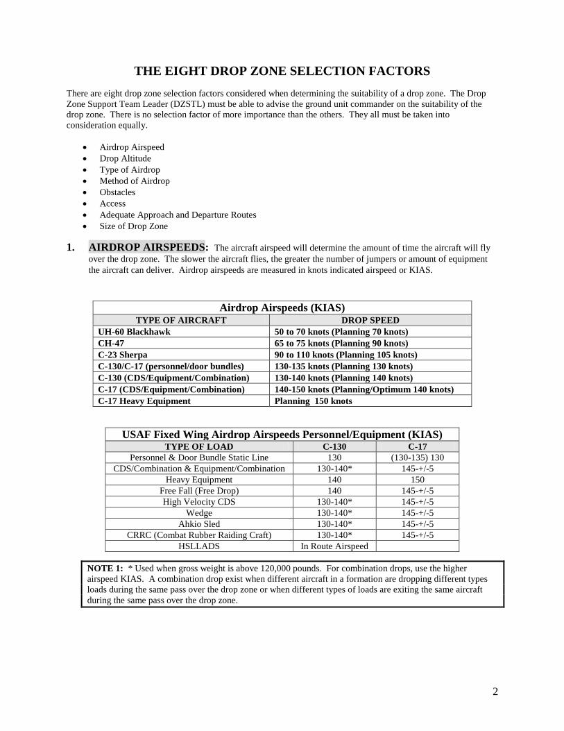
1. AIRDROP AIRSPEEDS: The aircraft airspeed will determine the amount of time the aircraft will fly
over the drop zone. The slower the aircraft flies, the greater the number of jumpers or amount of equipment the aircraft can deliver. Airdrop airspeeds are measured in knots indicated airspeed or KIAS.
NOTE 1: * Used when gross weight is above 120,000 pounds. For combination drops, use the higher airspeed KIAS. A combination drop exist when different aircraft in a formation are dropping different types loads during the same pass over the drop zone or when different types of loads are exiting the same aircraft during the same pass over the drop zone.
Airdrop Airspeeds (KIAS) TYPE OF AIRCRAFT DROP SPEED
UH-60 Blackhawk 50 to 70 knots (Planning 70 knots) CH-47 65 to 75 knots (Planning 90 knots) C-23 Sherpa 90 to 110 knots (Planning 105 knots) C-130/C-17 (personnel/door bundles) 130-135 knots (Planning 130 knots) C-130 (CDS/Equipment/Combination) 130-140 knots (Planning 140 knots) C-17 (CDS/Equipment/Combination) 140-150 knots (Planning/Optimum 140 knots) C-17 Heavy Equipment Planning 150 knots
USAF Fixed Wing Airdrop Airspeeds Personnel/Equipment (KIAS) TYPE OF LOAD C-130 C-17
Personnel & Door Bundle Static Line 130 (130-135) 130 CDS/Combination & Equipment/Combination 130-140* 145-+/-5
Heavy Equipment 140 150 Free Fall (Free Drop) 140 145-+/-5 High Velocity CDS 130-140* 145-+/-5
Wedge 130-140* 145-+/-5 Ahkio Sled 130-140* 145-+/-5
CRRC (Combat Rubber Raiding Craft) 130-140* 145-+/-5 HSLLADS In Route Airspeed
3
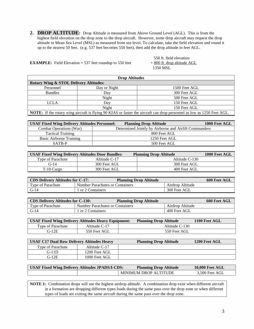
2. DROP ALTITUDE: Drop Altitude is measured from Above Ground Level (AGL). This is from the highest field elevation on the drop zone to the drop aircraft. However, some drop aircraft may request the drop altitude in Mean Sea Level (MSL) as measured from sea level. To calculate, take the field elevation and round it up to the nearest 50 feet. (e.g. 537 feet becomes 550 feet), then add the drop altitude in feet AGL.
550 ft. field elevation EXAMPLE: Field Elevation = 537 feet roundup to 550 feet + 800 ft. drop altitude AGL 1350 MSL
Drop Altitudes Rotary Wing & STOL Delivery Altitudes:
Personnel Day or Night 1500 Feet AGL Bundles Day 300 Feet AGL
Night 500 Feet AGL LCLA Day 150 Feet AGL
Night 150 Feet AGL NOTE: If the rotary wing aircraft is flying 90 KIAS or faster the aircraft can drop personnel as low as 1250 Feet AGL. USAF Fixed Wing Delivery Altitudes Personnel: Planning Drop Altitude 1000 Feet AGL
Combat Operations (War) Determined Jointly by Airborne and Airlift Commanders Tactical Training 800 Feet AGL
Basic Airborne Training 1250 Feet AGL SATB-P 500 Feet AGL
USAF Fixed Wing Delivery Altitudes Door Bundles: Planning Drop Altitude 1000 Feet AGL
Type of Parachute Altitude C-17 Altitude C-130 G-14 300 Feet AGL 300 Feet AGL
T-10 Cargo 300 Feet AGL 400 Feet AGL CDS Delivery Altitudes for C-17: Planning Drop Altitude 600 Feet AGL Type of Parachute Number Parachutes or Containers Airdrop Altitude G-14 1 or 2 Containers 300 Feet AGL CDS Delivery Altitudes for C-130: Planning Drop Altitude 600 Feet AGL Type of Parachute Number Parachutes or Containers Airdrop Altitude G-14 1 or 2 Containers 400 Feet AGL USAF Fixed Wing Delivery Altitudes Heavy Equipment: Planning Drop Altitude 1100 Feet AGL
Type of Parachute Altitude C-17 Altitude C-130 G-12E 550 Feet AGL 550 Feet AGL
USAF C17 Dual Row Delivery Altitudes Heavy Planning Drop Altitude 1200 Feet AGL
Type of Parachute Altitude C-17 G-11D 1200 Feet AGL G-12E 1000 Feet AGL
USAF Fixed Wing Delivery Altitudes JPADS/I-CDS: Planning Drop Altitude 10,000 Feet AGL
MINIMUM DROP ALTITUDE 3,500 Feet AGL
NOTE 1: Combination drops will use the highest airdrop altitude. A combination drop exist when different aircraft in a formation are dropping different types loads during the same pass over the drop zone or when different types of loads are exiting the same aircraft during the same pass over the drop zone.
4
NOTE 2: Minimum airdrop altitude for heavy equipment using the 5000-pound parachute release is 1000 feet AGL
or by parachute type (which ever is higher). 3. TYPES OF AIRDROP: There are three types of delivery for airdrop items. They are low velocity, high
velocity, and free drop. The method of delivery will normally determine the location of the control center. The primary difference between the methods of delivery is the type of parachute used or the lack of a parachute and the loads being delivered.
Low Velocity: Utilized for sensitive equipment and personnel drops. The canopy attached is used to slow the
rate of decent to prevent damage to equipment or injury to the jumper. High Velocity: The chute is designed to stabilize the load and reduce the rate of descent to a magnitude, which
ensures acceptable landing shock. Free Drop: Used for non-sensitive items only. No parachute is attached to the load NOTE 1: When determining the suitability of the drop zone and considering method of delivery, caution
should be taken when using high velocity or free drop around built up areas or airfields because risk of damage to buildings or airstrips.
4. METHODS OF AIRDROP: The type of load and the method it exits the aircraft will determine the
amount of time it takes for the load to exit based on drop zone type.
Personnel and Door Bundles: This type of airdrop load self-exits, is pushed, or is skidded from the paratroop/aircraft door or aircraft ramp.
Personnel:
On all drop zones allow one second for each jumper to exit the aircraft. The one-second interval begins after the first jumper exits the aircraft. For example, 10 jumpers require 9 seconds to exit the aircraft. Door Bundles: On GMRS and VIRS drop zones allow three seconds for each door bundle to exit the aircraft. The three-second interval begins after the first bundle exits the aircraft. For example, 3 door bundles require 6 seconds to exit the aircraft. On CARP drop zones door bundles are treated the same as personnel. For CDS and Heavy Equipment, the time requirement between loads is already factored into the minimum CARP DZ sizes found in AFI 13-217. NOTE 1: There is no set amount of time to wait in between exiting bundles and personnel, however the jumpmaster team must ensure all bundles have been exited from the aircraft and that no unsafe condition exist before starting to exit personal in accordance with FM 3-21.220 chapter 10. Under no circumstances will bundles and personnel ever exit the aircraft simultaneously.
Gravity: The aircraft maintains a “nose-high” attitude (if required) and in-flight release of load restraint allows the load to roll out of the aircraft. A rigging system may be used to initiate and accelerate load movement.
Extraction: An extraction parachute pulls the load from the cargo compartment.
5
5. OBSTACLES: The DZSTL is responsible for conducting a reconnaissance and declaring obstacles on and
near the drop zone.
Obstacles to personnel: Any feature, either natural or man-made that would pose a hazard to the jumper or prevent the jumper from accomplishing his or her mission.
Obstacles to equipment: Any feature, either natural or man-made that may hinder the recovery of the load or
cause damage to a load. Three Primary Obstacles:
TREES: 35 feet or higher impeding recovery of personnel or equipment. (35 feet is the distance from the top of a personnel parachute to the harness.) WATER: 4 feet deep or deeper AND 40 feet wide at the widest point, within 1000 meters of any edge of the DZ. The DZSTL can declare any body of water a water obstacle. POWER LINES: For the purpose of this publication, all restrictions apply to aerial power lines operating at 50 volts or greater.
1. Power lines present a significant hazard to jumpers. Jumpers can sustain life threatening injuries from electric shock and/or falls from a collapsed canopy. 2. To reduce this hazard, first attempt to site DZ so no power lines are located within 1000 meters of any DZ boundary. 3. If power lines are located within 1,000 meters of any boundary, coordinate with the Power Company to shut off power NLT 15 minutes prior to TOT. 4. If power cannot be interrupted, the flying mission commander, aircrew, and jumpmaster must conduct a risk assessment of the mission. Include as a minimum; type jump, jumper experience, aircrew experience, ceiling, and surface/altitude wind limits required to approve, suspend, or cancel the operation. To further minimize risks, consider altering the mission profile to raise/lower drop altitudes, change DZ run-in/escape headings, or remove inexperienced jumpers from the stick. If possible, mark power lines with visual markings (lights, smoke, or VS-17 panels). WARNING: At no time will military personnel attempt to climb power line poles to position or affix markings to wires or poles.
6. ACCESS: Avoid major obstacles to personnel and equipment between the drop zone and the objective.
Ensure that adequate routes are available for equipment recovery. 7. ADEQUATE APPROACH AND DEPARTURE ROUTES: Routes for the aircraft both into and
away from the drop zone must be considered. * No-Fly areas. * Obstacles to the aircraft, e.g. TV towers, high-tension lines, etc. * Terrain higher than the drop zone. * Enemy situation and location.
8. SIZE OF THE DROP ZONE:
Verbally Initiated Release System (VIRS) size dictated by FM 3-21.38 Ground Marked Release System (GMRS) size dictated by USASOC Reg. 350-2 Computed Air Release Point (CARP) size dictated by AFI 13-217
6
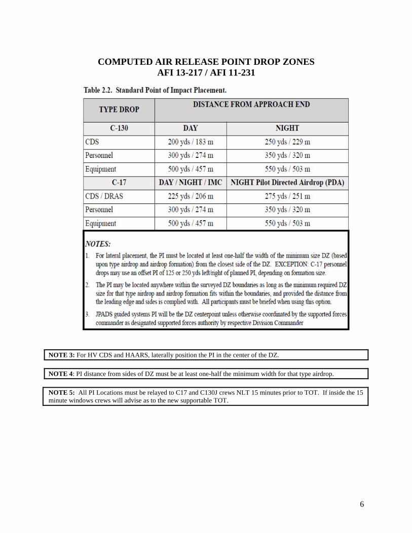
COMPUTED AIR RELEASE POINT DROP ZONES
AFI 13-217 / AFI 11-231
NOTE 3: For HV CDS and HAARS, laterally position the PI in the center of the DZ. NOTE 4: PI distance from sides of DZ must be at least one-half the minimum width for that type airdrop. NOTE 5: All PI Locations must be relayed to C17 and C130J crews NLT 15 minutes prior to TOT. If inside the 15 minute windows crews will advise as to the new supportable TOT.
7
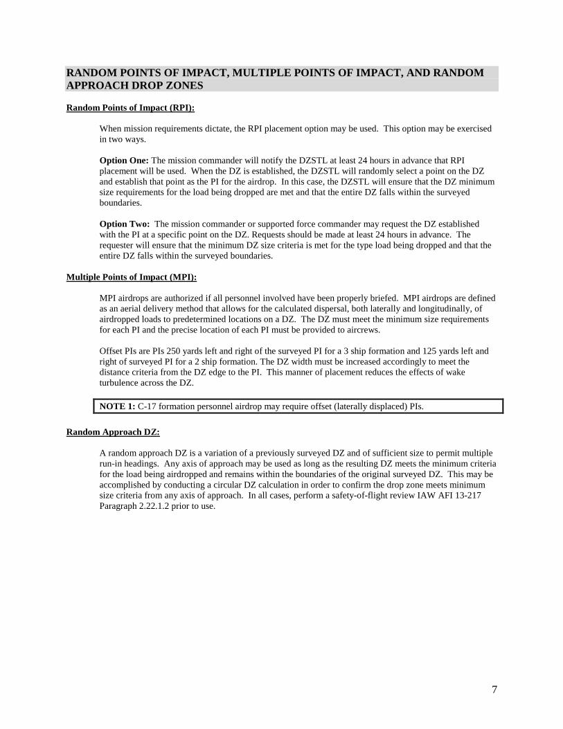
RANDOM POINTS OF IMPACT, MULTIPLE POINTS OF IMPACT, AND RANDOM APPROACH DROP ZONES Random Points of Impact (RPI):
When mission requirements dictate, the RPI placement option may be used. This option may be exercised in two ways. Option One: The mission commander will notify the DZSTL at least 24 hours in advance that RPI placement will be used. When the DZ is established, the DZSTL will randomly select a point on the DZ and establish that point as the PI for the airdrop. In this case, the DZSTL will ensure that the DZ minimum size requirements for the load being dropped are met and that the entire DZ falls within the surveyed boundaries. Option Two: The mission commander or supported force commander may request the DZ established with the PI at a specific point on the DZ. Requests should be made at least 24 hours in advance. The requester will ensure that the minimum DZ size criteria is met for the type load being dropped and that the entire DZ falls within the surveyed boundaries.
Multiple Points of Impact (MPI):
MPI airdrops are authorized if all personnel involved have been properly briefed. MPI airdrops are defined as an aerial delivery method that allows for the calculated dispersal, both laterally and longitudinally, of airdropped loads to predetermined locations on a DZ. The DZ must meet the minimum size requirements for each PI and the precise location of each PI must be provided to aircrews. Offset PIs are PIs 250 yards left and right of the surveyed PI for a 3 ship formation and 125 yards left and right of surveyed PI for a 2 ship formation. The DZ width must be increased accordingly to meet the distance criteria from the DZ edge to the PI. This manner of placement reduces the effects of wake turbulence across the DZ.
NOTE 1: C-17 formation personnel airdrop may require offset (laterally displaced) PIs.
Random Approach DZ:
A random approach DZ is a variation of a previously surveyed DZ and of sufficient size to permit multiple run-in headings. Any axis of approach may be used as long as the resulting DZ meets the minimum criteria for the load being airdropped and remains within the boundaries of the original surveyed DZ. This may be accomplished by conducting a circular DZ calculation in order to confirm the drop zone meets minimum size criteria from any axis of approach. In all cases, perform a safety-of-flight review IAW AFI 13-217 Paragraph 2.22.1.2 prior to use.
8
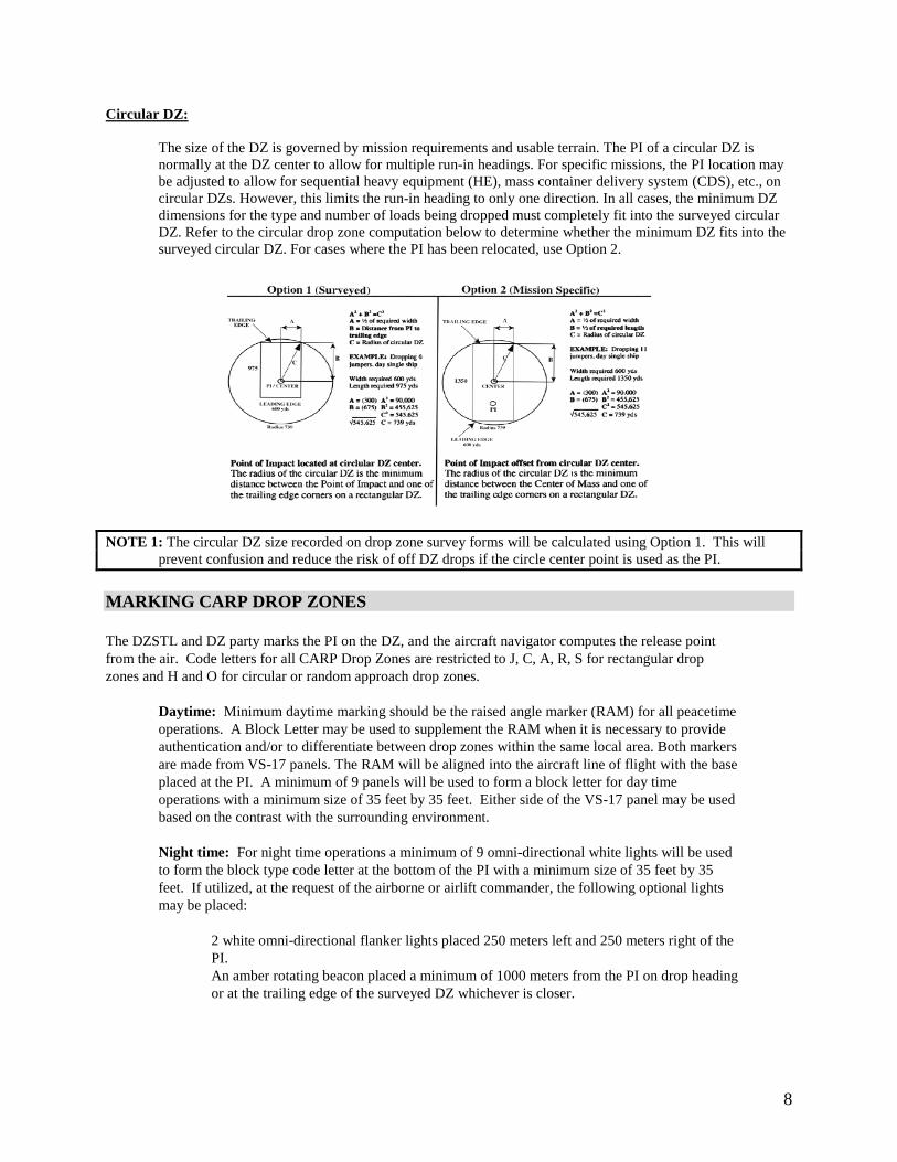
Circular DZ:
The size of the DZ is governed by mission requirements and usable terrain. The PI of a circular DZ is normally at the DZ center to allow for multiple run-in headings. For specific missions, the PI location may be adjusted to allow for sequential heavy equipment (HE), mass container delivery system (CDS), etc., on circular DZs. However, this limits the run-in heading to only one direction. In all cases, the minimum DZ dimensions for the type and number of loads being dropped must completely fit into the surveyed circular DZ. Refer to the circular drop zone computation below to determine whether the minimum DZ fits into the surveyed circular DZ. For cases where the PI has been relocated, use Option 2.
NOTE 1: The circular DZ size recorded on drop zone survey forms will be calculated using Option 1. This will
prevent confusion and reduce the risk of off DZ drops if the circle center point is used as the PI.
MARKING CARP DROP ZONES
The DZSTL and DZ party marks the PI on the DZ, and the aircraft navigator computes the release point from the air. Code letters for all CARP Drop Zones are restricted to J, C, A, R, S for rectangular drop zones and H and O for circular or random approach drop zones.
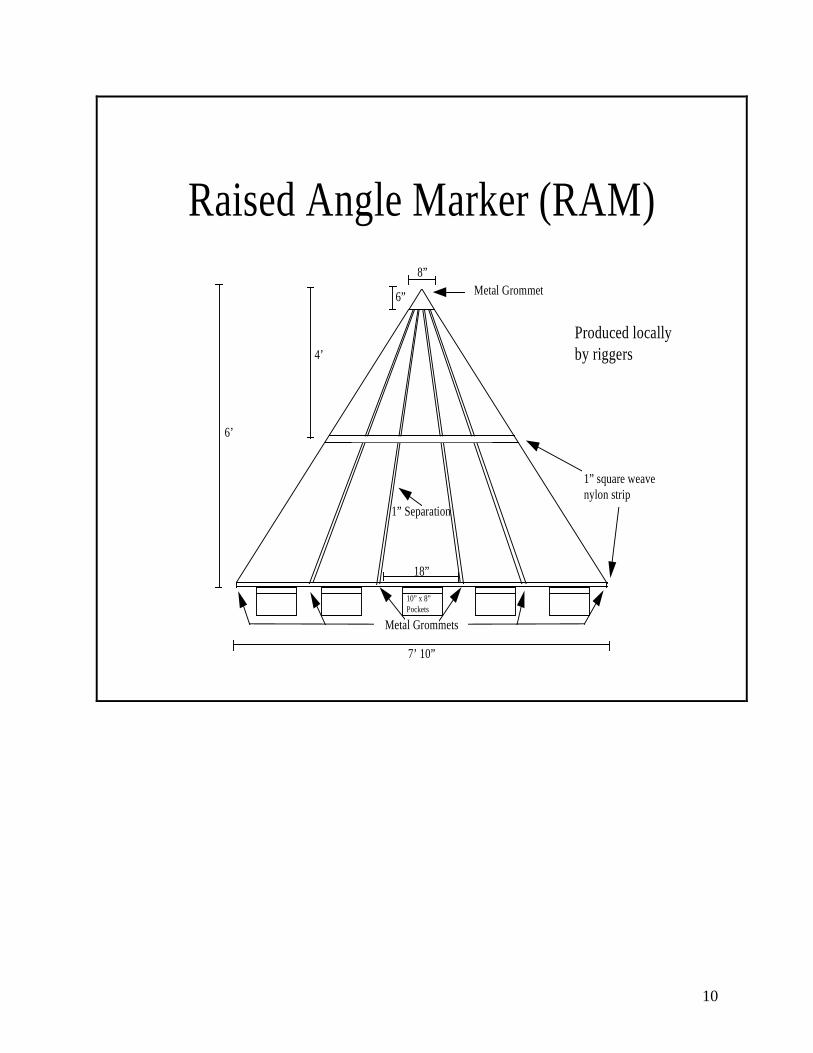
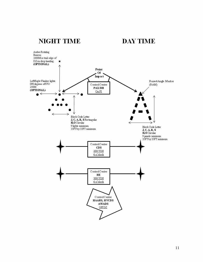
Daytime: Minimum daytime marking should be the raised angle marker (RAM) for all peacetime operations. A Block Letter may be used to supplement the RAM when it is necessary to provide authentication and/or to differentiate between drop zones within the same local area. Both markers are made from VS-17 panels. The RAM will be aligned into the aircraft line of flight with the base placed at the PI. A minimum of 9 panels will be used to form a block letter for day time operations with a minimum size of 35 feet by 35 feet. Either side of the VS-17 panel may be used based on the contrast with the surrounding environment. Night time: For night time operations a minimum of 9 omni-directional white lights will be used to form the block type code letter at the bottom of the PI with a minimum size of 35 feet by 35 feet. If utilized, at the request of the airborne or airlift commander, the following optional lights may be placed:
2 white omni-directional flanker lights placed 250 meters left and 250 meters right of the PI. An amber rotating beacon placed a minimum of 1000 meters from the PI on drop heading or at the trailing edge of the surveyed DZ whichever is closer.
9
NOTE 1: A circular/random approach drop zone is one that does not have a predetermined drop heading. Therefore, the aircraft can approach the drop zone from any direction. The PI markings are the only markings required on a circular CARP drop zone. NOTE 2: The panels in the block code letter are not elevated. NOTE 3: For Multiple Points of Impact, the surveyed PI will be marked IAW regulations and aircrews will briefed on the location of offset PIs.
CONTROL CENTER LOCATIONS (CARP Drop Zones)
The control center is the location where the DZSTL will control and observe the airborne operation. This is one of the locations where wind readings are taken. The DZSTL should have all radios, signaling devices, and appropriate forms positioned at the control center. The location of the control center will be determined by the type of mission: Personnel drops/door bundles: Control center is located at the PI. CDS drops: Control center is located 200 yards to the 6 o'clock off the PI. Heavy equipment drops: Control center is located 300 yards to the 6 o’clock off the PI
High Velocity/High Altitude Aerial Release System (HAARS), Free drops, and AWADS: Control center will be located off the drop zone. However, it should be located so that the approaching aircraft can be observed along with the PI if possible. For example the leading edge may be a poor location due to obstruction by the wood line.
NOTE 1: Ceiling of 600 feet or less requires control center for all drops to be located off the drop zone
10
Raised Angle Marker (RAM)Metal Grommet
8”
6”
4’
6’
7’ 10”
Metal Grommets
10” x 8”Pockets
18”
1” Separation
1” square weavenylon strip
Produced locallyby riggers
11
12
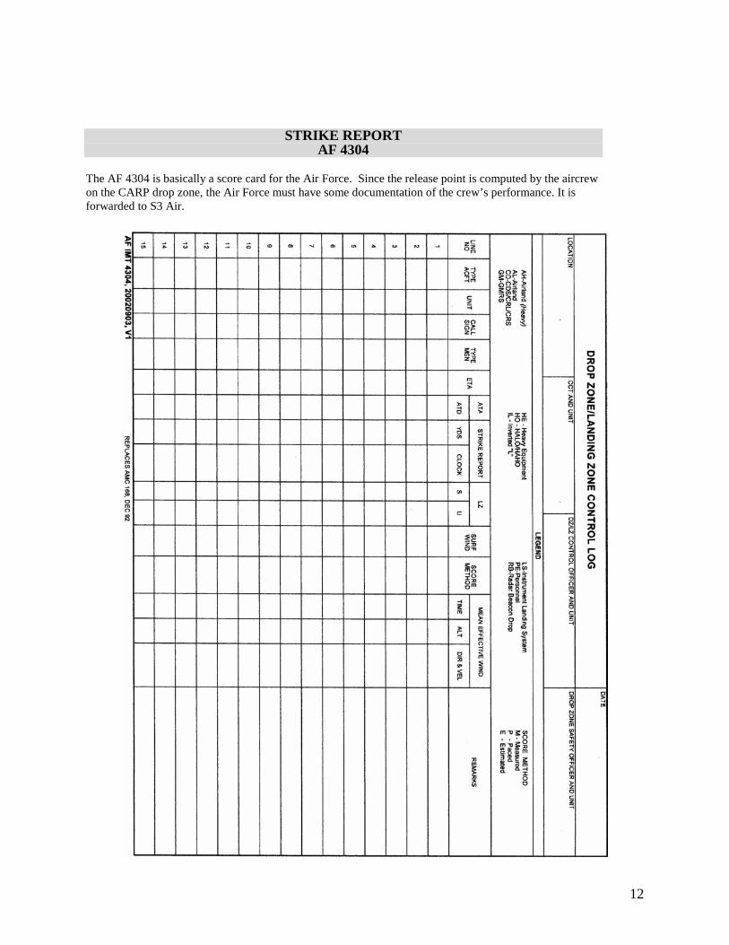
STRIKE REPORT AF 4304
The AF 4304 is basically a score card for the Air Force. Since the release point is computed by the aircrew on the CARP drop zone, the Air Force must have some documentation of the crew’s performance. It is forwarded to S3 Air.
13
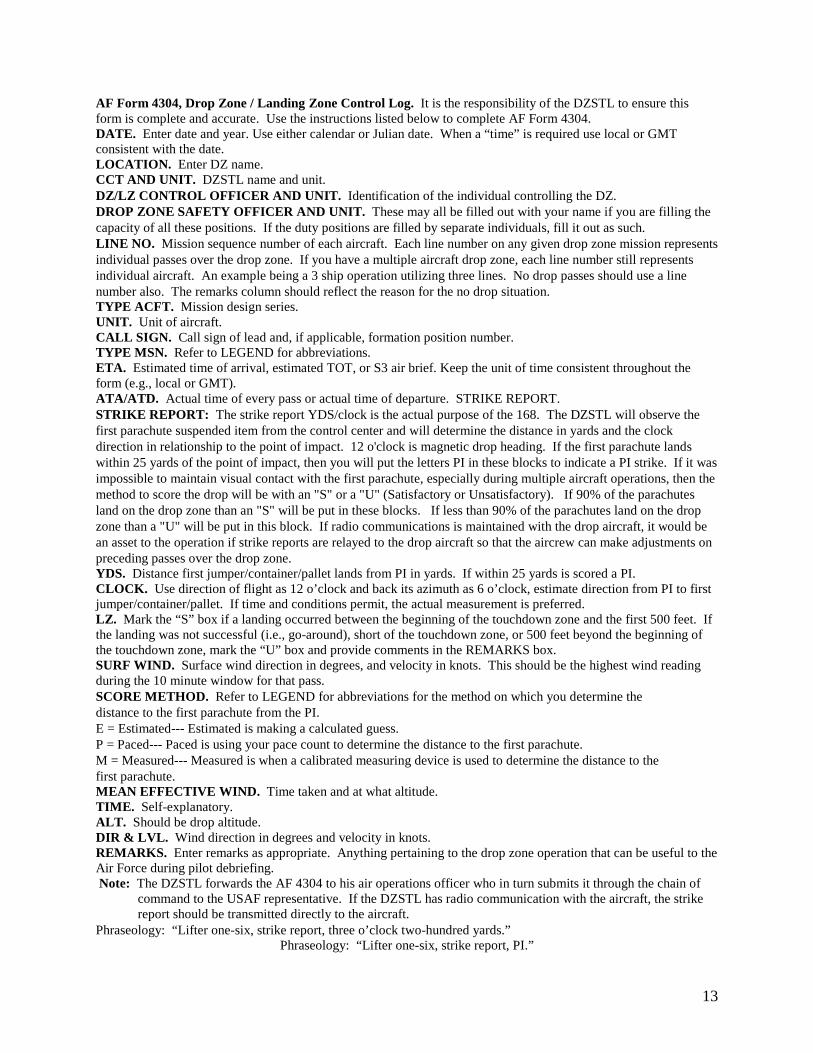
AF Form 4304, Drop Zone / Landing Zone Control Log. It is the responsibility of the DZSTL to ensure this form is complete and accurate. Use the instructions listed below to complete AF Form 4304. DATE. Enter date and year. Use either calendar or Julian date. When a “time” is required use local or GMT consistent with the date. LOCATION. Enter DZ name. CCT AND UNIT. DZSTL name and unit. DZ/LZ CONTROL OFFICER AND UNIT. Identification of the individual controlling the DZ. DROP ZONE SAFETY OFFICER AND UNIT. These may all be filled out with your name if you are filling the capacity of all these positions. If the duty positions are filled by separate individuals, fill it out as such. LINE NO. Mission sequence number of each aircraft. Each line number on any given drop zone mission represents individual passes over the drop zone. If you have a multiple aircraft drop zone, each line number still represents individual aircraft. An example being a 3 ship operation utilizing three lines. No drop passes should use a line number also. The remarks column should reflect the reason for the no drop situation. TYPE ACFT. Mission design series. UNIT. Unit of aircraft. CALL SIGN. Call sign of lead and, if applicable, formation position number. TYPE MSN. Refer to LEGEND for abbreviations. ETA. Estimated time of arrival, estimated TOT, or S3 air brief. Keep the unit of time consistent throughout the form (e.g., local or GMT). ATA/ATD. Actual time of every pass or actual time of departure. STRIKE REPORT. STRIKE REPORT: The strike report YDS/clock is the actual purpose of the 168. The DZSTL will observe the first parachute suspended item from the control center and will determine the distance in yards and the clock direction in relationship to the point of impact. 12 o'clock is magnetic drop heading. If the first parachute lands within 25 yards of the point of impact, then you will put the letters PI in these blocks to indicate a PI strike. If it was impossible to maintain visual contact with the first parachute, especially during multiple aircraft operations, then the method to score the drop will be with an "S" or a "U" (Satisfactory or Unsatisfactory). If 90% of the parachutes land on the drop zone than an "S" will be put in these blocks. If less than 90% of the parachutes land on the drop zone than a "U" will be put in this block. If radio communications is maintained with the drop aircraft, it would be an asset to the operation if strike reports are relayed to the drop aircraft so that the aircrew can make adjustments on preceding passes over the drop zone. YDS. Distance first jumper/container/pallet lands from PI in yards. If within 25 yards is scored a PI. CLOCK. Use direction of flight as 12 o’clock and back its azimuth as 6 o’clock, estimate direction from PI to first jumper/container/pallet. If time and conditions permit, the actual measurement is preferred. LZ. Mark the “S” box if a landing occurred between the beginning of the touchdown zone and the first 500 feet. If the landing was not successful (i.e., go-around), short of the touchdown zone, or 500 feet beyond the beginning of the touchdown zone, mark the “U” box and provide comments in the REMARKS box. SURF WIND. Surface wind direction in degrees, and velocity in knots. This should be the highest wind reading during the 10 minute window for that pass. SCORE METHOD. Refer to LEGEND for abbreviations for the method on which you determine the distance to the first parachute from the PI. E = Estimated--- Estimated is making a calculated guess. P = Paced--- Paced is using your pace count to determine the distance to the first parachute. M = Measured--- Measured is when a calibrated measuring device is used to determine the distance to the first parachute. MEAN EFFECTIVE WIND. Time taken and at what altitude. TIME. Self-explanatory. ALT. Should be drop altitude. DIR & LVL. Wind direction in degrees and velocity in knots. REMARKS. Enter remarks as appropriate. Anything pertaining to the drop zone operation that can be useful to the Air Force during pilot debriefing. Note: The DZSTL forwards the AF 4304 to his air operations officer who in turn submits it through the chain of
command to the USAF representative. If the DZSTL has radio communication with the aircraft, the strike report should be transmitted directly to the aircraft.
Phraseology: “Lifter one-six, strike report, three o’clock two-hundred yards.” Phraseology: “Lifter one-six, strike report, PI.”
14
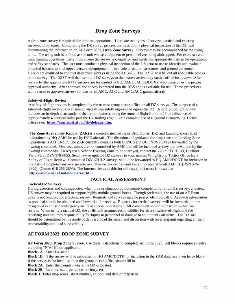
Drop Zone Surveys
A drop zone survey is required for airborne operations. There are two types of surveys, tactical and existing surveyed drop zones. Completing the DZ survey process involves both a physical inspection of the DZ, and documenting the information on AF Form 3823, Drop Zone Survey. Surveys may be accomplished by the using units. The using unit is defined as the unit whose equipment or personnel are being airdropped. For exercises and joint training operations, users must ensure the survey is completed and meets the appropriate criteria for operational and safety standards. The user must conduct a physical inspection of the DZ prior to use to identify and evaluate potential hazards to airdropped personnel/equipment, man-made or natural structures, and ground personnel. DZSTs are qualified to conduct drop zone surveys using the AF 3823. The DZST will fill out all applicable blocks in the survey. The DZST will then send the DZ surveys to the nearest active duty tactics office for review. After review by the appropriate RTO, surveys are forwarded to HQ, AMC TACC/DOOXY who determines the proper approval authority. After approval the survey is entered into the BBS and is available for use. These procedures will be used to approve surveys for use by all AMC, ACC and AMC/ACC gained aircraft. Safety-of-Flight Review A safety-of-flight review is completed by the nearest group tactics office on all DZ surveys. The purpose of a safety-of-flight review is to ensure an aircraft can safely ingress and egress the DZ. A safety-of-flight review includes an in-depth chart study of the terrain features along the route of flight from the IP to a distance of approximately 4 nautical miles past the DZ trailing edge. For a complete list of Regional Group/Wing Tactics offices see: https://amc.scott.af.mil/do/dok/zar.htm.
The Zone Availability Report (ZAR) is a consolidated listing of Drop Zones (DZ) and Landing Zones (LZ) maintained by HQ AMC for use by DOD aircraft. The direction and guidance for drop zone and Landing Zone Operations is AFI 13-217. The ZAR currently contains both CONUS and OCONUS surveys forwarded by the owning command. Overseas zones are not controlled by AMC but will be included as they are forwarded by the owning commands. To request a New or Existing Zone to be surveyed, contact the 720th STG/DOO, Hurlburt Field FL at DSN 579-6055. Send new or updated DZ surveys to your nearest Wing/Group Tactics Office for a Safety of Flight Review. Completed DZ/LZ/HLZ surveys should be forwarded to HQ AMC/DOKT for inclusion in the ZAR. Completed surveys are also available via fax-on demand system located at Scott AFB, IL (DSN 576-2899), (Comm 618 256-2899). The Internet site available for military (.mil) users is located at https://amc.scott.af.mil/do/dok/zar.htm.
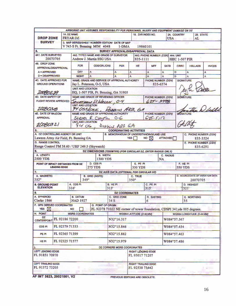
TACTICAL ASSESSMENT Tactical DZ Surveys. During exercises and contingencies, when time or situation do not permit completion of a full DZ survey, a tactical DZ survey may be required to support highly mobile ground forces. Though preferable, the use of an AF Form 3823 is not required for a tactical survey. Requests and surveys may be passed electronically. As much information as practical should be obtained and forwarded for review. Requests for tactical surveys will be forwarded to the designated exercise / contingency airlift or special operations airlift component senior representative for final review. When using a tactical DZ, the airlift unit assumes responsibility for aircraft safety-of-flight and the receiving unit assumes responsibility for injury to personnel or damage to equipment / air items. The DZ size should be determined by the mode of delivery, load dispersal, and discussion with receiving unit regarding air item recoverability and load survivability. AF FORM 3823, DROP ZONE SURVEY AF Form 3823, Drop Zone Survey. Use these instructions to complete AF Form 3823. All blocks require an entry including “N/A” if non-applicable. Block 1A. Enter DZ name. Block 1B. If the survey will be submitted to HQ AMC/DOTK for inclusion in the ZAR database, then leave blank. If the survey is for local use then the group tactics office should fill in. Block 2A. Enter the Country where the DZ is located. Block 2B. Enter the state, province, territory, etc. Block 3. Enter map series, sheet number, edition, and date of map used.
15
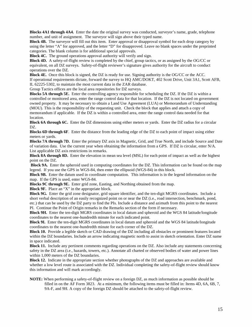
Blocks 4A1 through 4A4. Enter the date the original survey was conducted, surveyor’s name, grade, telephone number, and unit of assignment. The surveyor will sign above their typed name. Block 4B. The surveyor will fill out this item. Enter approval or disapproval symbol for each drop category by using the letter “A” for approved, and the letter “D” for disapproved. Leave no blank spaces under the preprinted categories. The blank column is for additional special approvals. Block 4C. The ground operations approval authority will verify and sign. Block 4D. A safety-of-flight review is completed by the chief, group tactics, or as assigned by the OG/CC or equivalent, on all DZ surveys. Safety-of-flight reviewer’s signature gives authority for the aircraft to conduct operations over the DZ. Block 4E. Once this block is signed, the DZ is ready for use. Signing authority is the OG/CC or the ACC. If operational requirements dictate, forward the survey to HQ AMC/DOKT, 402 Scott Drive, Unit 3A1, Scott AFB, IL 62225-5302, to maintain the most current data in the ZAR database. Group Tactics offices are the local area repositories for DZ surveys. Blocks 5A through 5E. Enter the controlling agency responsible for scheduling the DZ. If the DZ is within a controlled or monitored area, enter the range control data for that location. If the DZ is not located on government owned property. It may be necessary to obtain a Land Use Agreement (LUA) or Memorandum of Understanding (MOU). This is the responsibility of the requesting unit. Check the block that applies and attach a copy of memorandum if applicable. If the DZ is within a controlled area, enter the range control data needed for that location. Block 6A through 6C. Enter the DZ dimensions using either meters or yards. Enter the DZ radius for a circular DZ. Blocks 6D through 6F. Enter the distance from the leading edge of the DZ to each point of impact using either meters or yards. Blocks 7A through 7D. Enter the primary DZ axis in Magnetic, Grid, and True North, and include Source and Date of variation data. Use the current year when obtaining the information from a GPS. If DZ is circular, enter N/A. List applicable DZ axis restrictions in remarks. Block 8A through 8D. Enter the elevation in mean sea level (MSL) for each point of impact as well as the highest point on the DZ. Block 9A. Enter the spheroid used in computing coordinates for the DZ. This information can be found on the map legend. If you use the GPS in WGS-84, then enter the ellipsoid (WGS-84) in this block. Block 9B. Enter the datum used in coordinate computation. This information is in the legend information on the map. If the GPS is used, enter WGS-84. Blocks 9C through 9E. Enter grid zone, Easting, and Northing obtained from the map. Block 9F. Place an “X” in the appropriate block. Block 9G. Enter the grid zone designator, grid square identifier, and the ten-digit MGRS coordinates. Include a short verbal description of an easily recognized point on or near the DZ (i.e., road intersection, benchmark, pond, etc.) that can be used by the DZ party to find the PIs. Include a distance and azimuth from this point to the nearest PI. Continue the Point of Origin remarks in the Remarks section of the form if necessary. Block 9H. Enter the ten-digit MGRS coordinates in local datum and spheroid and the WGS 84 latitude/longitude coordinates to the nearest one-hundredth minute for each indicated point. Block 9I. Enter the ten-digit MGRS coordinates in local datum and spheroid and the WGS 84 latitude/longitude coordinates to the nearest one-hundredth minute for each corner of the DZ. Block 10. Provide a legible sketch or CAD drawing of the DZ including all obstacles or prominent features located within the DZ boundaries. Include an arrow indicating magnetic north to assist in sketch orientation. Enter DZ name in space indicated. Block 11. Include any pertinent comments regarding operations on the DZ. Also include any statements concerning safety in the DZ area (i.e., hazards, towers, etc.). Annotate all charted or observed bodies of water and power lines within 1,000 meters of the DZ boundaries. Block 12. Indicate in the appropriate section whether photographs of the DZ and approaches are available and whether a low level route is associated with the DZ. Individual completing the safety-of-flight review should know this information and will mark accordingly. NOTE: When performing a safety-of-flight review on a foreign DZ, as much information as possible should be
filled in on the AF Form 3823. At a minimum, the following items must be filled in: Items 4D, 6A, 6B, 7, 9A-F, and 9H. A copy of the foreign DZ should be attached to the safety-of-flight review.
16
17
18
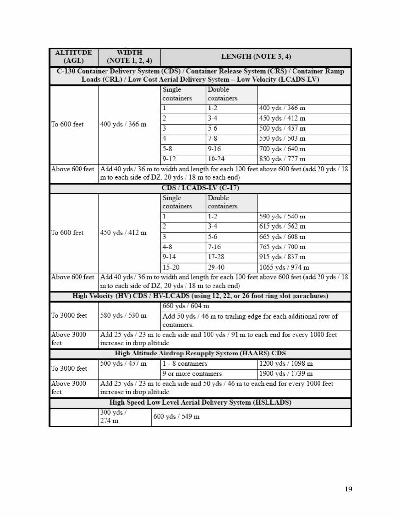
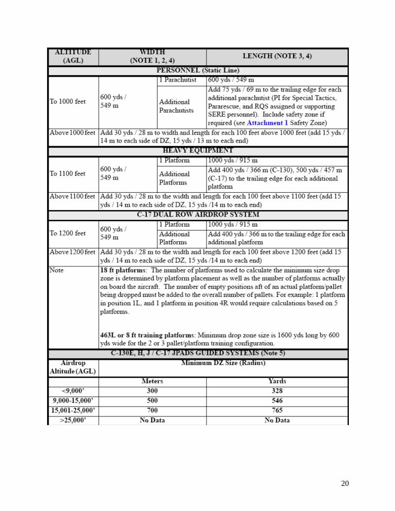
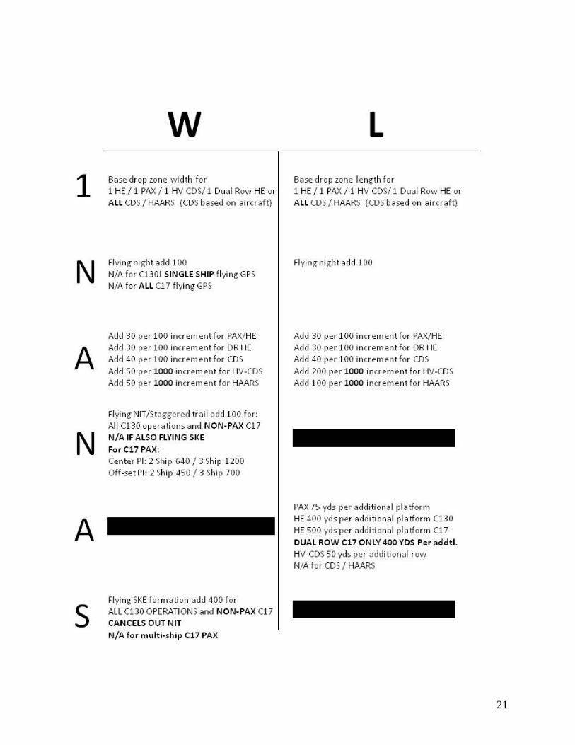
CARP DROP ZONE SIZES Established and possible CARP drop zones have size requirements that must be met in order to accommodate a variety of missions such as personnel, heavy equipment and various CDS. DZSTL may be expected to calculate drop zone size requirements to accomplish a survey for a specific mission, or be expected to specify what can be delivered in one or multiple passed for an existing and surveyed drop zone. Both of these duties require the DSZTL to be able to apply restrictions and guidance from AFI 13-217 and AFI 11-231 to safely execute the airborne operations to meet ground commander’s intent. Essential to the process of these calculations is the minimum drop zone size requirements or “CARP Charts” from AFI 13-217 extracted below:
19
20
21
22
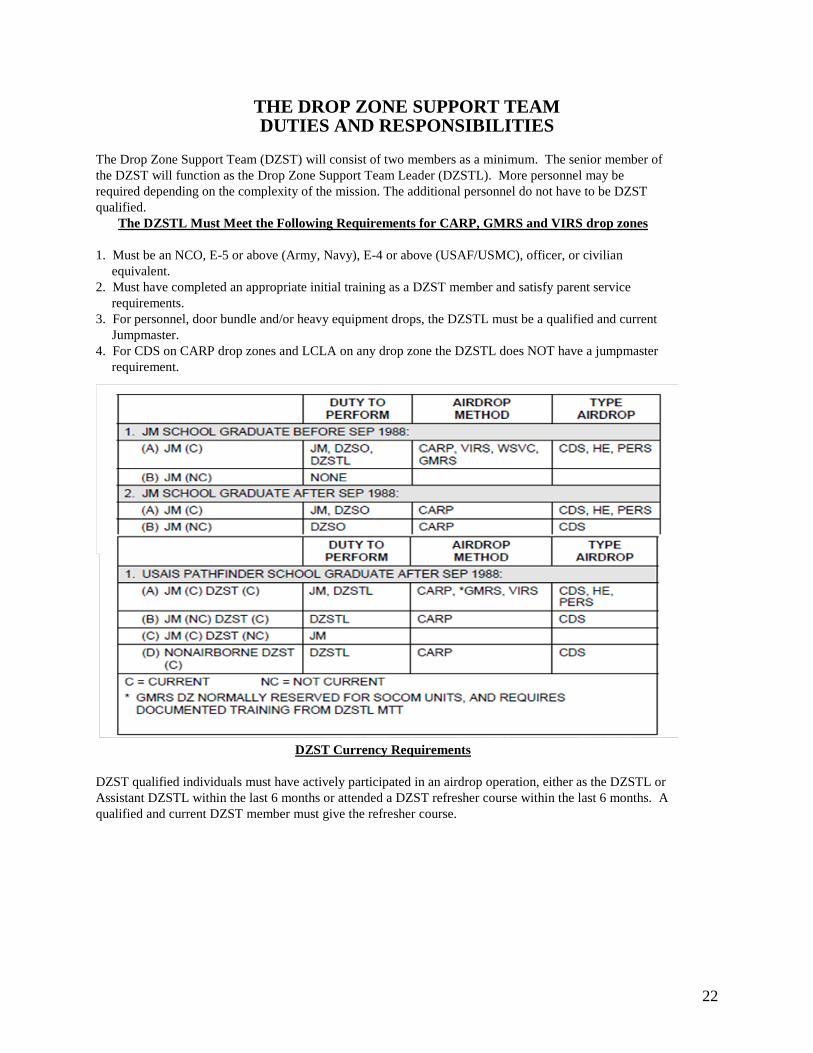
THE DROP ZONE SUPPORT TEAM DUTIES AND RESPONSIBILITIES
The Drop Zone Support Team (DZST) will consist of two members as a minimum. The senior member of the DZST will function as the Drop Zone Support Team Leader (DZSTL). More personnel may be required depending on the complexity of the mission. The additional personnel do not have to be DZST qualified.
The DZSTL Must Meet the Following Requirements for CARP, GMRS and VIRS drop zones
1. Must be an NCO, E-5 or above (Army, Navy), E-4 or above (USAF/USMC), officer, or civilian equivalent.
2. Must have completed an appropriate initial training as a DZST member and satisfy parent service requirements.
3. For personnel, door bundle and/or heavy equipment drops, the DZSTL must be a qualified and current Jumpmaster.
4. For CDS on CARP drop zones and LCLA on any drop zone the DZSTL does NOT have a jumpmaster requirement.
DZST Currency Requirements
DZST qualified individuals must have actively participated in an airdrop operation, either as the DZSTL or Assistant DZSTL within the last 6 months or attended a DZST refresher course within the last 6 months. A qualified and current DZST member must give the refresher course.
23
Missions of the DZSTL Primary Missions:
1. Wartime CDS drops to battalion or smaller size units. 2. Wartime LCLA (Low Cost Low Altitude) drops to battalion or smaller size units. 3. Peacetime Visual Meteorological Conditions (VMC) drops involving 1-3 aircraft for personnel,
door bundles, LCLA, CDS and heavy equipment. Secondary Missions:
1. Wartime drops, brigade size or larger units. 2. Peacetime C-130 AWADS (Adverse Weather Aerial Delivery System) involving 1-3 aircraft. 3. VMC drops of 4 or more aircraft for personnel, door bundles, LCLA, CDS, and heavy equipment.
NOTE: Authorized personnel other than qualified combat controllers performing DZSTL duties are restricted to formation airdrops of four or less aircraft unless on a military range with active range control.
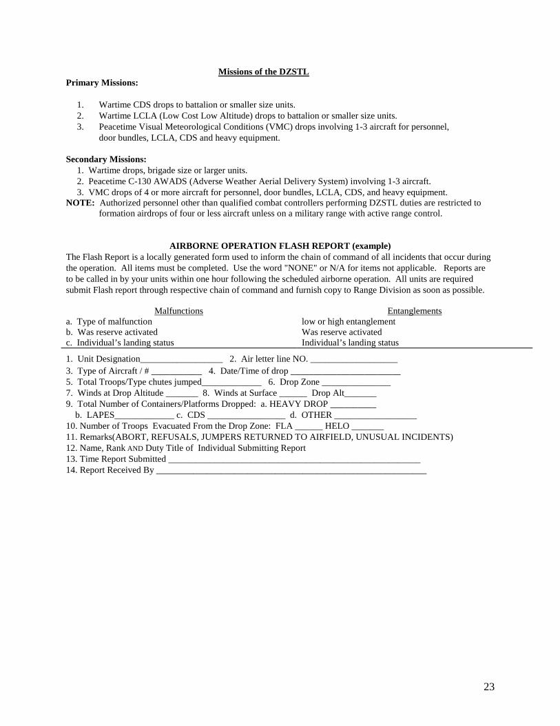
AIRBORNE OPERATION FLASH REPORT (example) The Flash Report is a locally generated form used to inform the chain of command of all incidents that occur during the operation. All items must be completed. Use the word "NONE" or N/A for items not applicable. Reports are to be called in by your units within one hour following the scheduled airborne operation. All units are required submit Flash report through respective chain of command and furnish copy to Range Division as soon as possible.
Malfunctions Entanglements a. Type of malfunction low or high entanglement b. Was reserve activated Was reserve activated c. Individual’s landing status Individual’s landing status
1. Unit Designation__________________ 2. Air letter line NO. ___________________ 3. Type of Aircraft / # ___________ 4. Date/Time of drop ________________________ 5. Total Troops/Type chutes jumped_____________ 6. Drop Zone _______________ 7. Winds at Drop Altitude _______ 8. Winds at Surface ______ Drop Alt_______ 9. Total Number of Containers/Platforms Dropped: a. HEAVY DROP __________ b. LAPES_____________ c. CDS _________________ d. OTHER __________________ 10. Number of Troops Evacuated From the Drop Zone: FLA ______ HELO _______ 11. Remarks(ABORT, REFUSALS, JUMPERS RETURNED TO AIRFIELD, UNUSUAL INCIDENTS) 12. Name, Rank AND Duty Title of Individual Submitting Report 13. Time Report Submitted _______________________________________________________ 14. Report Received By ___________________________________________________________
24
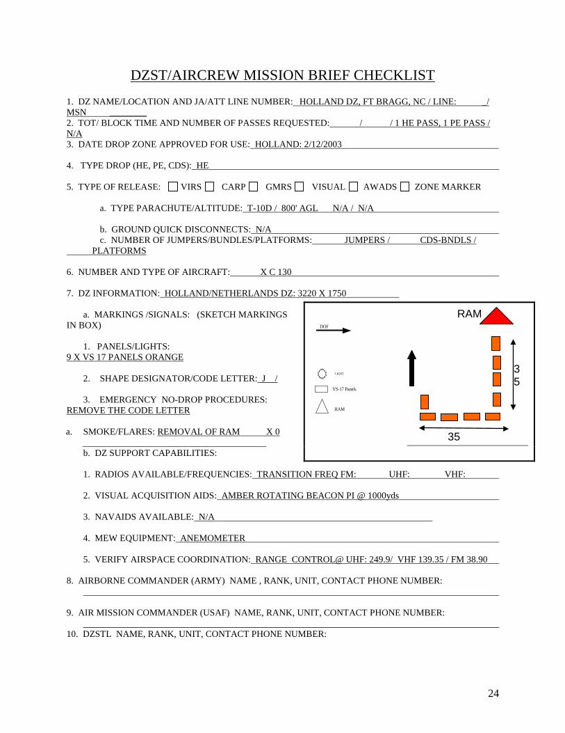
DZST/AIRCREW MISSION BRIEF CHECKLIST 1. DZ NAME/LOCATION AND JA/ATT LINE NUMBER: HOLLAND DZ, FT BRAGG, NC / LINE: _/ MSN ________ 2. TOT/ BLOCK TIME AND NUMBER OF PASSES REQUESTED: / / 1 HE PASS, 1 PE PASS / N/A 3. DATE DROP ZONE APPROVED FOR USE: HOLLAND: 2/12/2003 4. TYPE DROP (HE, PE, CDS): HE 5. TYPE OF RELEASE: VIRS CARP GMRS VISUAL AWADS ZONE MARKER a. TYPE PARACHUTE/ALTITUDE: T-10D / 800' AGL N/A / N/A b. GROUND QUICK DISCONNECTS: N/A c. NUMBER OF JUMPERS/BUNDLES/PLATFORMS: JUMPERS / CDS-BNDLS / PLATFORMS 6. NUMBER AND TYPE OF AIRCRAFT: X C 130 7. DZ INFORMATION: HOLLAND/NETHERLANDS DZ: 3220 X 1750 a. MARKINGS /SIGNALS: (SKETCH MARKINGS IN BOX) 1. PANELS/LIGHTS: 9 X VS 17 PANELS ORANGE
2. SHAPE DESIGNATOR/CODE LETTER: J / 3. EMERGENCY NO-DROP PROCEDURES: REMOVE THE CODE LETTER a. SMOKE/FLARES: REMOVAL OF RAM X 0
b. DZ SUPPORT CAPABILITIES: 1. RADIOS AVAILABLE/FREQUENCIES: TRANSITION FREQ FM: UHF: VHF: 2. VISUAL ACQUISITION AIDS: AMBER ROTATING BEACON PI @ 1000yds 3. NAVAIDS AVAILABLE: N/A 4. MEW EQUIPMENT: ANEMOMETER 5. VERIFY AIRSPACE COORDINATION: RANGE CONTROL@ UHF: 249.9/ VHF 139.35 / FM 38.90 8. AIRBORNE COMMANDER (ARMY) NAME , RANK, UNIT, CONTACT PHONE NUMBER: 9. AIR MISSION COMMANDER (USAF) NAME, RANK, UNIT, CONTACT PHONE NUMBER: 10. DZSTL NAME, RANK, UNIT, CONTACT PHONE NUMBER:
RAM
35
35
DOF
VS-17 Panels
RAM
LIGHT
25
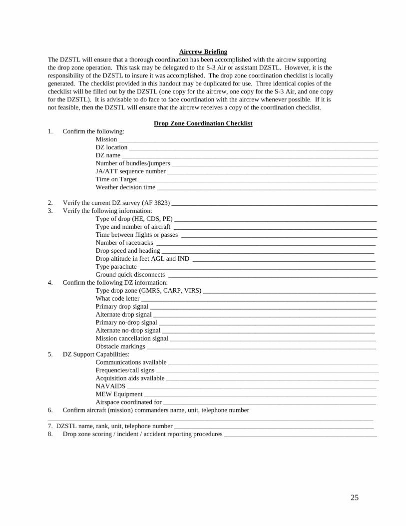
Aircrew Briefing The DZSTL will ensure that a thorough coordination has been accomplished with the aircrew supporting the drop zone operation. This task may be delegated to the S-3 Air or assistant DZSTL. However, it is the responsibility of the DZSTL to insure it was accomplished. The drop zone coordination checklist is locally generated. The checklist provided in this handout may be duplicated for use. Three identical copies of the checklist will be filled out by the DZSTL (one copy for the aircrew, one copy for the S-3 Air, and one copy for the DZSTL). It is advisable to do face to face coordination with the aircrew whenever possible. If it is not feasible, then the DZSTL will ensure that the aircrew receives a copy of the coordination checklist.
Drop Zone Coordination Checklist 1. Confirm the following: Mission ______________________________________________________________________________ DZ location ___________________________________________________________________________ DZ name _____________________________________________________________________________ Number of bundles/jumpers ______________________________________________________________ JA/ATT sequence number _______________________________________________________________ Time on Target ________________________________________________________________________ Weather decision time __________________________________________________________________ 2. Verify the current DZ survey (AF 3823) ______________________________________________________________ 3. Verify the following information: Type of drop (HE, CDS, PE) _____________________________________________________________ Type and number of aircraft _____________________________________________________________ Time between flights or passes ___________________________________________________________ Number of racetracks __________________________________________________________________ Drop speed and heading ________________________________________________________________ Drop altitude in feet AGL and IND _______________________________________________________ Type parachute _______________________________________________________________________ Ground quick disconnects _______________________________________________________________ 4. Confirm the following DZ information: Type drop zone (GMRS, CARP, VIRS) ____________________________________________________ What code letter _______________________________________________________________________ Primary drop signal ____________________________________________________________________ Alternate drop signal ___________________________________________________________________ Primary no-drop signal _________________________________________________________________ Alternate no-drop signal ________________________________________________________________ Mission cancellation signal ______________________________________________________________ Obstacle markings _____________________________________________________________________ 5. DZ Support Capabilities: Communications available _______________________________________________________________ Frequencies/call signs ___________________________________________________________________ Acquisition aids available ________________________________________________________________ NAVAIDS ___________________________________________________________________________ MEW Equipment ______________________________________________________________________ Airspace coordinated for ________________________________________________________________ 6. Confirm aircraft (mission) commanders name, unit, telephone number __________________________________________________________________________________________________ 7. DZSTL name, rank, unit, telephone number ____________________________________________________________ 8. Drop zone scoring / incident / accident reporting procedures ______________________________________________
26
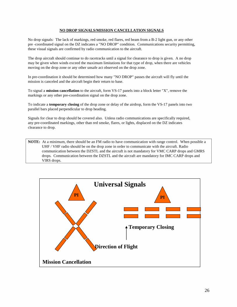
Universal Signals
Temporary Closing Direction of Flight Mission Cancellation
NO DROP SIGNALS/MISSION CANCELLATION SIGNALS No drop signals: The lack of markings, red smoke, red flares, red beam from a B-2 light gun, or any other pre -coordinated signal on the DZ indicates a "NO DROP" condition. Communications security permitting, these visual signals are confirmed by radio communication to the aircraft. The drop aircraft should continue to do racetracks until a signal for clearance to drop is given. A no drop may be given when winds exceed the maximum limitations for that type of drop, when there are vehicles moving on the drop zone or any other unsafe act observed on the drop zone. In pre-coordination it should be determined how many "NO DROP" passes the aircraft will fly until the mission is canceled and the aircraft begin their return to base. To signal a mission cancellation to the aircraft, form VS-17 panels into a block letter "X", remove the markings or any other pre-coordination signal on the drop zone. To indicate a temporary closing of the drop zone or delay of the airdrop, form the VS-17 panels into two parallel bars placed perpendicular to drop heading. Signals for clear to drop should be covered also. Unless radio communications are specifically required, any pre-coordinated markings, other than red smoke, flares, or lights, displaced on the DZ indicates clearance to drop.
NOTE: At a minimum, there should be an FM radio to have communication with range control. When possible a
UHF / VHF radio should be on the drop zone in order to communicate with the aircraft. Radio communication between the DZSTL and the aircraft is not mandatory for VMC CARP drops and GMRS drops. Communication between the DZSTL and the aircraft are mandatory for IMC CARP drops and VIRS drops.
PI PI
27
DZ SUPPORT REQUIREMENTS The DZSTL will ensure that the proper equipment to support the operation is available and that the support requirements that make up the drop zone control group are also available. Equipment needed for each DZ 10 VS-17 panels 1 raised angle marker (RAM) CARP DZ only 40 tent pegs 1 roll 1/4 inch cotton webbing 1 helium source 1 pi-ball kit 2 smoke grenades, yellow, green or white for each TOT 1 smoke grenade, red, for each TOT 1 shovel or E-tool 1 1:50,000 or 1:25,000 map of area of operations 2 lensatic compasses 1 signal mirror 1 tree recovery kit consisting of: 1 120' rope /w D-rings 1 pair of tree climbers 1 ax or chainsaw 1 or 2 wind measuring device(s): AN/PMQ-3A,Turbo meter, or DIC/DIC3 For night operations include the following: 11 white omni directional lights (beanbag, Whelen etc.) 1 light gun (SE-11, B-2, MAG) Must have a visual range of three miles w/red filter capabilities 1 strobe light 2 sets of night vision devices (1 for the DZSTL, & 1 for Malfunctions Officer) 1 amber rotating beacon DZSTL BOOK: Consisting of Range Control SOP, AF 3823 of DZ, Blank AF 4304s, MEDEVAC procedures and
anything covered by unit SOP. NOTE: Other equipment may be needed as a result of pre-mission coordination or unit SOP.
Drop Zone Support Group
The DZSTL will ensure that support requirements that make up the drop zone control group are coordinated for and in place no later that one hour prior to TOT. There are two support groups; a complete support group and a partial support group. If the drop zone is 2100 meters or longer in length or 20 seconds or more of exit time or more than one aircraft is executing the mission then a complete control group must be used. If none of these situations exist then a partial control group may be used. Differences between a complete an partial control group:
Complete control group: 1. The assistant DZSTL must be DZSTL qualified (For personnel and / or heavy equipment drops, the
assistant DZSTL must be a qualified and current Jumpmaster.) 2. Two medical personnel /w Front Line Ambulance (FLA) minimum for personnel drops and heavy
equipment (Not needed for CDS drops. Check local rules and regulations on the subject). 3. 2 wind measuring devices (one located at the control center with the DZSTL, the second wind
measuring device will be located with the assistant DZSTL at the highest location on the drop zone).
28
Partial control group: 1. The assistant DZSTL does not have to be DZSTL or Jumpmaster qualified. 2. One medical person /w Front Line Ambulance (FLA) minimum for personnel drops and heavy
equipment (Not needed for CDS drops. Check local rules and regulations on the subject). 3. 1 wind measuring device (located at the control center with the DZSTL).
The following is an example a drop zone support team/control group: * DZSTL. The senior ranking of the DZST qualified individuals. * Assistant DZSTL. * Medical personnel /w Front Line Ambulance (FLA) minimum for personnel drops and heavy equipment (Not needed for CDS drops. Check local rules and regulations on the subject). * Malfunction officer /w camera. Must be a qualified and current rigger IAW AR 59-4. * Parachute recovery detail /w recovery kit. * Vehicles /w drivers as required. * Road guards as required. * Military Police if required to control traffic or provide crowd control. * Boat detail for PE drops only NOTE: The boat detail is required for personnel drops if a water obstacle is within 1000 meters of any
edge of the drop zone, 40ft wide or wider at it widest point AND is four feet deep or deeper at its deepest point. If the water is 4 feet deep or deeper, but not over 40 feet wide, a boat detail is not required. However, approved life preservers are still required for all the jumpers. The DZSTL may declare any body of water an obstacle based on jumper safety.
The DZSTL must: (a) Determine if a follow-on assessment of the DZ has been conducted to confirm the current status. (b) Ensure the OIC/NCOIC is fully briefed on the plan. Ensure all boat detail personnel have been trained and have
all necessary equipment available to conduct the mission. (c) Read all applicable regulations, FMs, and SOPs. Ensure copies are present throughout mission. Water Obstacle Coverage: The boat detail must: have a minimum of 2 boats in place 1hr prior to TOT, establish Two-way communication with the DZSTL 1hr prior to TOT, maintain communication throughout the jump operation. The boats will be in the water with engines running 10 minutes prior to TOT (No Drop situation exists if both boats are not in the water). The entire obstacle must be accessible to the boat detail. Each water obstacle may require a different type of coverage. The following is an example composition of a boat detail. (1) OIC/NCOIC (qualified as a boat operator) and assistant boat operator. Personnel assigned duties as safety boat
operators must be trained and licensed to operate the issued boat motors. (2) Qualified boat operators - 1 primary and 1 assistant for each boat. (3) Recovery personnel - 2 for each boat (one may be lifeguard qualified and combat lifesaver certified). All boat
detail personnel should be strong swimmers. (4) Each recovery boat team may need the following equipment:
· Boat (Zodiac RB-10 or solid-bodied boat of comparable size) with operable outboard motor. · Enough fuel/oil to complete the mission. · Life vest/floatation device for each boat detail member and 1 additional floatation devices for each jumper on the first pass. (not needed when the jumpers are wearing B5’s or B7’s. · Life ring with attached rope—1. · FM radio with spare battery—1. · Hand held radio with spare battery—1
29
· Shepherd’s crook—1. · Grappling hook—1. · Long backboard to facilitate CPR—1. · Aid bag with resuscitation equipment—1. · Rope, 120 feet long—1. · Sling ropes with end of line bowline and snap link per boat—4. · Paddles—4.
Night Operations: · Operational night vision devices with spare batteries—2. · Spot light—1. NOTE: Units may supplement these requirements. When making a training parachute jump DZ risk assessment, the commander should consider the proximity of the water obstacle to the DZ, the depth of the water obstacle, and the width of the water obstacle. Additionally, the following factors may enter into the water obstacle risk assessment: the condition of the water obstacle bottom, the current of a free-flowing water obstacle, water temperature, the number of obstacles, the equipment available to reduce the risk level, jumper experience levels, jump time (day or night and percent of illumination), and whether or not the selected DZ is critical to mission success.
DZSTL Duties * Conducts pre-mission coordination. * Opens the drop zone through range control. * Has the drop zone fully operational one hour prior to TOT to include support in place and DZ marking correctly
displayed. * Establishes communication with Departure Airfield Control Officer (DACO) no later than one hour prior to TOT. * Conducts ground or aerial reconnaissance of the drop zone at least one hour prior to the drop for obstacles or
safety hazards. * Conducts 10 minute window. * Operates all visual acquisition aids. * Ensures no-drop signals are relayed to the drop aircraft. * Controls all ground and air medical evacuations. * Closes the drop zone through range control when accountability of personnel, and equipment is completed. * Submits post mission reports to appropriate agency. Monitoring Surface Winds: Surface wind reading are taken from the control center location and from the highest field elevation on the drop zone when the DZ length is 2100 meters or longer, 20 seconds or more of exit time, or is a multiple aircraft operation. In the event of the surface winds exceeding the allowable limits, the DZSTL will immediately broadcast by radio "no drop, no drop, no drop" or execute the pre-coordinated no drop signal. The 10 Minute Window: Not later than 12 minutes prior to the first TOT a continuous monitoring of the surface wind will commence. If at any time the wind exceeds the maximum allowable surface wind conditions, then a no-drop signal will be relayed to the drop aircraft. The surface wind must then remain at/or below maximum surface wind conditions for 10 minutes before the drop operation can proceed. This procedure will continue until the wind remains at allowable conditions for 10 minutes or the mission is canceled. Example: TOT scheduled for 0900. Continuous monitoring of surface winds will begin at 0848. At 0855 a gust of
wind exceeds allowable conditions. The new TOT is 0905. Continuous monitoring of surface winds begins 12 minutes prior to TOT to allow a buffer of 2 minutes to relay a no-drop signal to the aircraft.
30
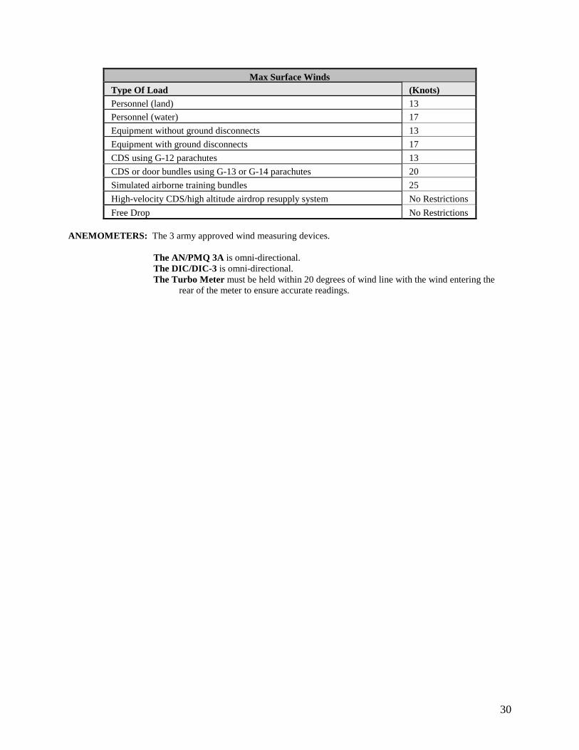
Max Surface Winds Type Of Load (Knots) Personnel (land) 13 Personnel (water) 17 Equipment without ground disconnects 13 Equipment with ground disconnects 17 CDS using G-12 parachutes 13 CDS or door bundles using G-13 or G-14 parachutes 20 Simulated airborne training bundles 25 High-velocity CDS/high altitude airdrop resupply system No Restrictions Free Drop No Restrictions
ANEMOMETERS: The 3 army approved wind measuring devices.
The AN/PMQ 3A is omni-directional. The DIC/DIC-3 is omni-directional. The Turbo Meter must be held within 20 degrees of wind line with the wind entering the
rear of the meter to ensure accurate readings.
31
ARMY VIRS When establishing a Ground Verbal Initiated Release System drop zone, the first phase of establishment is determining the release point location. Follow the steps below to establish the release point for such drop zones. 1. Determine drop heading. If the drop zone was surveyed and an AF 3823 was published for the drop zone, use
the magnetic course indicated. If the drop zone was surveyed as a circular DZ, or a tactical assessment was done on the drop zone, or the drop zone is being established as a ARMY VIRS, determine drop heading taking into consideration, long axis, wind direction, and obstacles on the approach and departure ends of the drop zone.
2. Determine the Point of Impact (PI). The PI for personnel will be centerline of the drop zone and 100 meters
from the leading edge. The PI for bundles will be centerline of the DZ and on the leading edge. These may be adjusted forward, left or right if necessary. For CDS, and Heavy Equipment, use the surveyed PI locations indicated on the AF 3823. If a tactical assessment was done in lieu of an AF 3823, use the CARP PI planning locations for CDS and Heavy Equipment. The size for CDS and Heavy Equipment drop zones will be determined by the CARP charts.
3. Determine wind direction and speed. This should be done using the PIBALL. The MEW is more accurate. If
PIBALL capabilities are not available then the surface wind direction and speed must be used. Once the wind direction and speed has been determined, calculate a D = K x A x V formula for drift in meters.
MEAN EFFECTIVE WIND
Mean effective wind is the average wind from ground level to drop altitude. It is measured by using the Pilot Balloon (PIBALL). If piball capabilities are not available then surface wind will be used. If you have communications with the aircraft, it is beneficial to the mission if you transmit the MEW to the aircrew before the first pass. It will assist them in calculating an accurate release point.
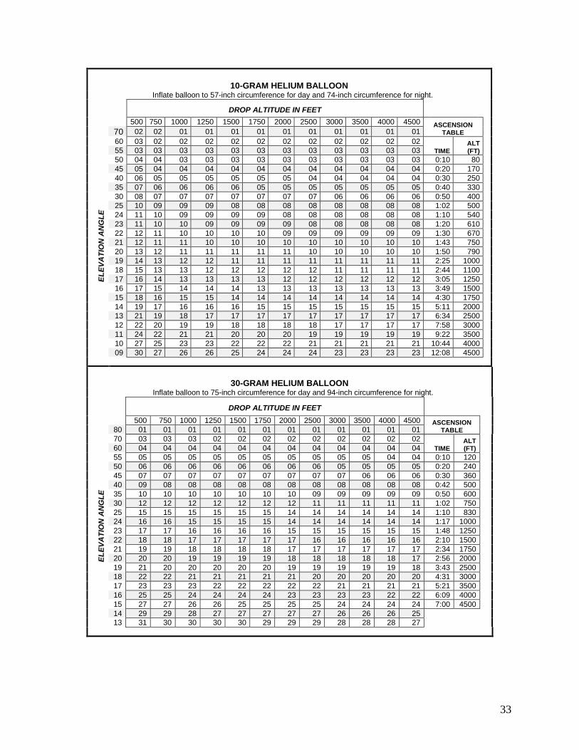
To get a PIBALL reading follow these steps: Refer to PIBALL chart below. Insure the correct chart is used for the type of PIBALL used. When using the 10 gram balloon be sure to use the 10 gram chart. Insure the same for the 30 gram balloon. The following equipment is required for MEW readings: * PIBALL (10 gram or 30 gram) * Helium source * Drift scale (zero to 90 degrees) * Stop watch with seconds * Compass PIBALL circumferences are as follows: -10 gram for day: 57 inches -10 gram for night: 74 inches -30 gram for day: 75 inches -30 gram for night: 94 inches Night piballs are filled to a larger circumference to compensate for the weight of a small liquid activated light that is attached to the balloon to assist in observation. This will ensure the balloon will have the same ascension rate as the day balloon. NOTE: A 6 inch chemlight may be used in place of the small liquid activated light.
32
STEP 1: Refer to the TIME/HEIGHT ascent rate column of the PIBALL chart. Determine the altitude of
the drop and the amount of time for balloon angle to be checked. STEP 2: Fill balloon up to the correct circumference w/helium. STEP 3: Release balloon and begin timing. STEP 4: Determine angle to the balloon at completion of time. STEP 5: Cross reference ANGLE to altitude on PIBALL chart for the MEW.
STEP 6: The magnetic azimuth to the balloon is measured and the reciprocal heading noted. This is the MEW wind direction to be reported.
Note: The MEW speed has NO influence on no-drop situations. Only the surface wind will determine whether a no-drop is applicable.
33
10-GRAM HELIUM BALLOON Inflate balloon to 57-inch circumference for day and 74-inch circumference for night.
DROP ALTITUDE IN FEET
500 750 1000 1250 1500 1750 2000 2500 3000 3500 4000 4500 ASCENSION TABLE
ELEV
ATI
ON
AN
GLE
70 02 02 01 01 01 01 01 01 01 01 01 01 60 03 02 02 02 02 02 02 02 02 02 02 02
TIME ALT (FT) 55 03 03 03 03 03 03 03 03 03 03 03 03
50 04 04 03 03 03 03 03 03 03 03 03 03 0:10 80 45 05 04 04 04 04 04 04 04 04 04 04 04 0:20 170 40 06 05 05 05 05 05 05 04 04 04 04 04 0:30 250 35 07 06 06 06 06 05 05 05 05 05 05 05 0:40 330 30 08 07 07 07 07 07 07 07 06 06 06 06 0:50 400 25 10 09 09 09 08 08 08 08 08 08 08 08 1:02 500 24 11 10 09 09 09 09 08 08 08 08 08 08 1:10 540 23 11 10 10 09 09 09 09 08 08 08 08 08 1:20 610 22 12 11 10 10 10 10 09 09 09 09 09 09 1:30 670 21 12 11 11 10 10 10 10 10 10 10 10 10 1:43 750 20 13 12 11 11 11 11 11 10 10 10 10 10 1:50 790 19 14 13 12 12 11 11 11 11 11 11 11 11 2:25 1000 18 15 13 13 12 12 12 12 12 11 11 11 11 2:44 1100 17 16 14 13 13 13 13 12 12 12 12 12 12 3:05 1250 16 17 15 14 14 14 13 13 13 13 13 13 13 3:49 1500 15 18 16 15 15 14 14 14 14 14 14 14 14 4:30 1750 14 19 17 16 16 16 15 15 15 15 15 15 15 5:11 2000 13 21 19 18 17 17 17 17 17 17 17 17 17 6:34 2500 12 22 20 19 19 18 18 18 18 17 17 17 17 7:58 3000 11 24 22 21 21 20 20 20 19 19 19 19 19 9:22 3500 10 27 25 23 23 22 22 22 21 21 21 21 21 10:44 4000 09 30 27 26 26 25 24 24 24 23 23 23 23 12:08 4500
30-GRAM HELIUM BALLOON Inflate balloon to 75-inch circumference for day and 94-inch circumference for night.
DROP ALTITUDE IN FEET
500 750 1000 1250 1500 1750 2000 2500 3000 3500 4000 4500 ASCENSION TABLE
ELEV
ATI
ON
AN
GLE
80 01 01 01 01 01 01 01 01 01 01 01 01 70 03 03 03 02 02 02 02 02 02 02 02 02
TIME ALT (FT) 60 04 04 04 04 04 04 04 04 04 04 04 04
55 05 05 05 05 05 05 05 05 05 05 04 04 0:10 120 50 06 06 06 06 06 06 06 06 05 05 05 05 0:20 240 45 07 07 07 07 07 07 07 07 07 06 06 06 0:30 360 40 09 08 08 08 08 08 08 08 08 08 08 08 0:42 500 35 10 10 10 10 10 10 10 09 09 09 09 09 0:50 600 30 12 12 12 12 12 12 12 11 11 11 11 11 1:02 750 25 15 15 15 15 15 15 14 14 14 14 14 14 1:10 830 24 16 16 15 15 15 15 14 14 14 14 14 14 1:17 1000 23 17 17 16 16 16 16 15 15 15 15 15 15 1:48 1250 22 18 18 17 17 17 17 17 16 16 16 16 16 2:10 1500 21 19 19 18 18 18 18 17 17 17 17 17 17 2:34 1750 20 20 20 19 19 19 19 18 18 18 18 18 17 2:56 2000 19 21 20 20 20 20 20 19 19 19 19 19 18 3:43 2500 18 22 22 21 21 21 21 21 20 20 20 20 20 4:31 3000 17 23 23 23 22 22 22 22 22 21 21 21 21 5:21 3500 16 25 25 24 24 24 24 23 23 23 23 22 22 6:09 4000 15 27 27 26 26 25 25 25 25 24 24 24 24 7:00 4500 14 29 29 28 27 27 27 27 27 26 26 26 25 13 31 30 30 30 30 29 29 29 28 28 28 27
34
4. Pace off the drift in meters into the wind. This should be the reciprocal heading of the PIBALL direction. If a
PIBALL was not used, then field expedient means of determining wind direction may be used. If the direction and distance of the drift are paced into the wood line, adjust the PI as necessary. Forward or left and right only.
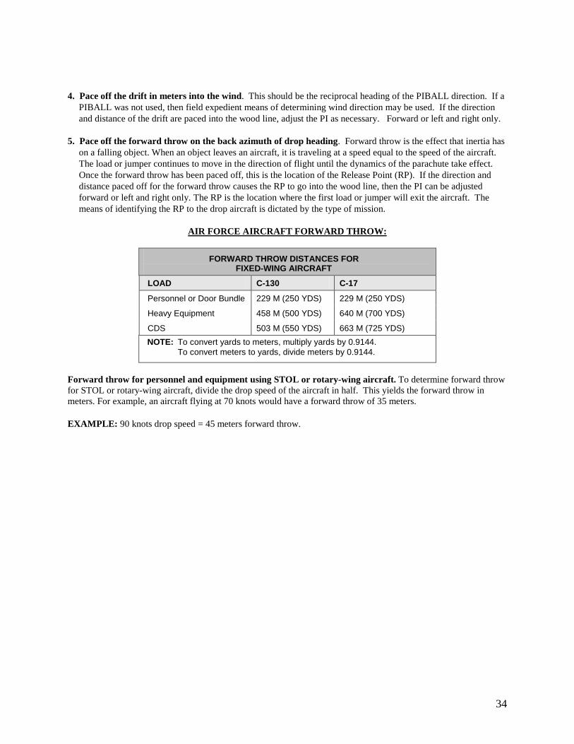
5. Pace off the forward throw on the back azimuth of drop heading. Forward throw is the effect that inertia has
on a falling object. When an object leaves an aircraft, it is traveling at a speed equal to the speed of the aircraft. The load or jumper continues to move in the direction of flight until the dynamics of the parachute take effect. Once the forward throw has been paced off, this is the location of the Release Point (RP). If the direction and distance paced off for the forward throw causes the RP to go into the wood line, then the PI can be adjusted forward or left and right only. The RP is the location where the first load or jumper will exit the aircraft. The means of identifying the RP to the drop aircraft is dictated by the type of mission.
AIR FORCE AIRCRAFT FORWARD THROW:
FORWARD THROW DISTANCES FOR FIXED-WING AIRCRAFT
LOAD C-130 C-17
Personnel or Door Bundle 229 M (250 YDS) 229 M (250 YDS)
Heavy Equipment 458 M (500 YDS) 640 M (700 YDS)
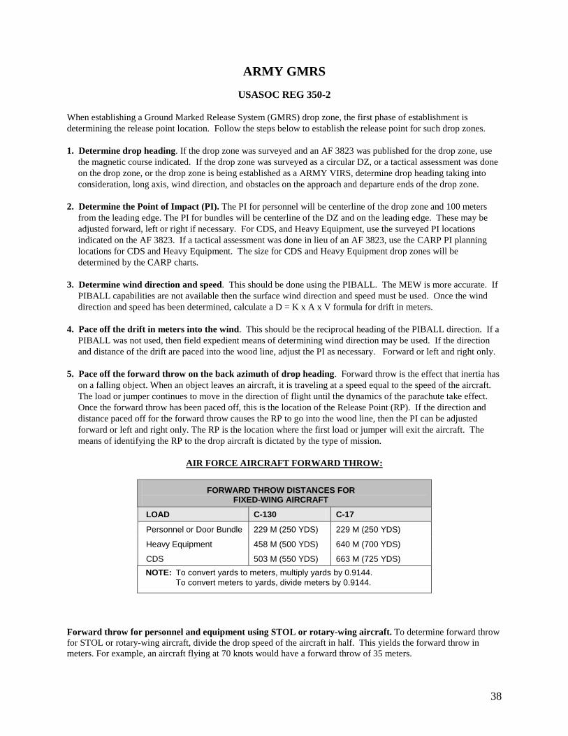
CDS 503 M (550 YDS) 663 M (725 YDS) NOTE: To convert yards to meters, multiply yards by 0.9144. To convert meters to yards, divide meters by 0.9144.
Forward throw for personnel and equipment using STOL or rotary-wing aircraft. To determine forward throw for STOL or rotary-wing aircraft, divide the drop speed of the aircraft in half. This yields the forward throw in meters. For example, an aircraft flying at 70 knots would have a forward throw of 35 meters. EXAMPLE: 90 knots drop speed = 45 meters forward throw.
35
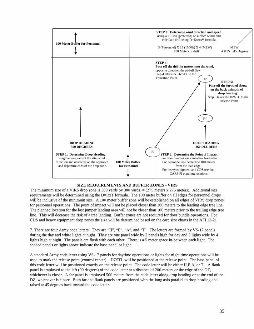
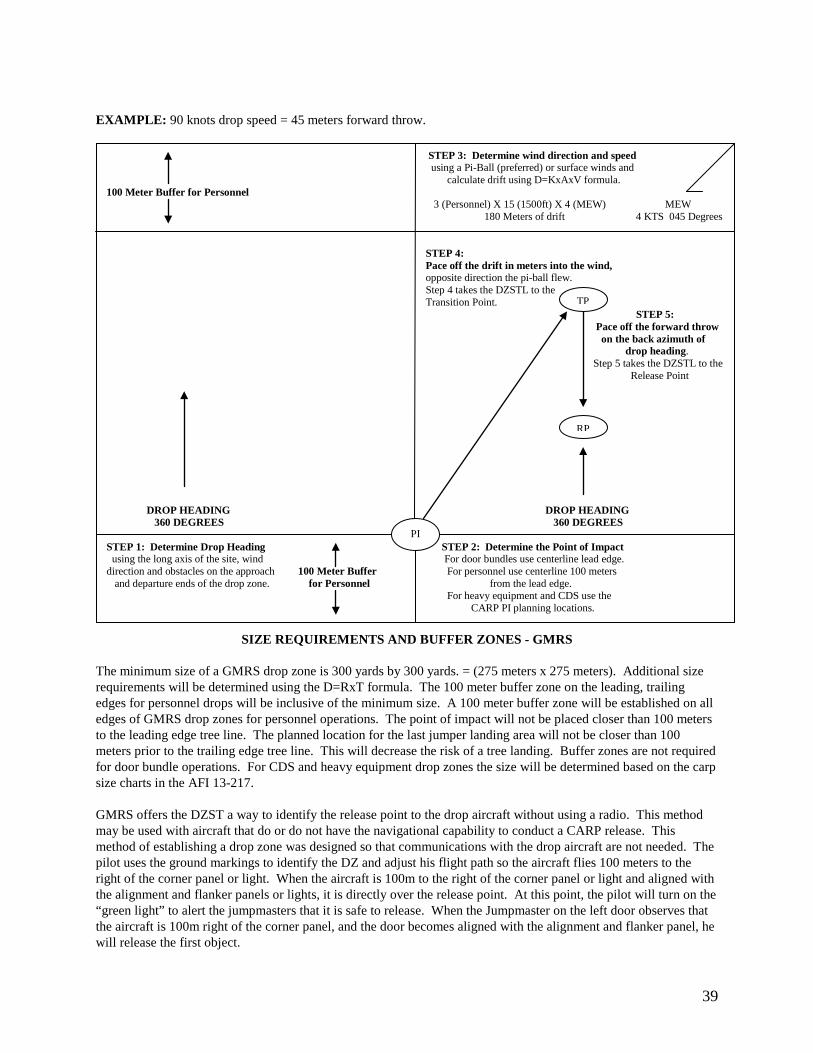
STEP 3: Determine wind direction and speed using a Pi-Ball (preferred) or surface winds and calculate drift using D=KxAxV formula. 100 Meter Buffer for Personnel 3 (Personnel) X 15 (1500ft) X 4 (MEW) MEW 180 Meters of drift 4 KTS 045 Degrees STEP 4:
Pace off the drift in meters into the wind, opposite direction the pi-ball flew. Step 4 takes the DZSTL to the Transition Point. STEP 5: Pace off the forward throw on the back azimuth of drop heading. Step 5 takes the DZSTL to the Release Point
DROP HEADING DROP HEADING 360 DEGREES 360 DEGREES STEP 1: Determine Drop Heading STEP 2: Determine the Point of Impact using the long axis of the site, wind For door bundles use centerline lead edge. direction and obstacles on the approach 100 Meter Buffer For personnel use centerline 100 meters and departure ends of the drop zone. for Personnel from the lead edge. For heavy equipment and CDS use the CARP PI planning locations.
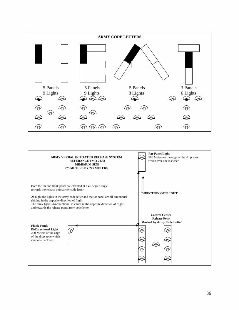
SIZE REQUIREMENTS AND BUFFER ZONES - VIRS The minimum size of a VIRS drop zone is 300 yards by 300 yards. = (275 meters x 275 meters). Additional size requirements will be determined using the D=RxT formula. The 100 meter buffer on all edges for personnel drops will be inclusive of the minimum size. A 100 meter buffer zone will be established on all edges of VIRS drop zones for personnel operations. The point of impact will not be placed closer than 100 meters to the leading edge tree line. The planned location for the last jumper landing area will not be closer than 100 meters prior to the trailing edge tree line. This will decrease the risk of a tree landing. Buffer zones are not required for door bundle operations. For CDS and heavy equipment drop zones the size will be determined based on the carp size charts in the AFI 13-21 7. There are four Army code letters. They are “H”, “E”, “A”, and “T”. The letters are formed by VS-17 panels during the day and white lights at night. They are one panel wide by 2 panels high for day and 3 lights wide by 4 lights high at night. The panels are flush with each other. There is a 5 meter space in-between each light. The shaded panels or lights above indicate the base panel or light.
A standard Army code letter using VS-17 panels for daytime operations or lights for night time operations will be used to mark the release point (control center) . DZSTL will be positioned at the release point. The base panel of this code letter will be positioned exactly on the release point. The code letter will be either H,E,A, or T. A flank panel is employed to the left (90 degrees) of the code letter at a distance of 200 meters or the edge of the DZ, whichever is closer. A far panel is employed 500 meters from the code letter along drop heading or at the end of the DZ, whichever is closer. Both far and flank panels are positioned with the long axis parallel to drop heading and raised at 45 degrees back toward the code letter.
TP
PI
RP
36
ARMY CODE LETTERS 5 Panels 5 Panels 5 Panels 3 Panels
9 Lights 9 Lights 8 Lights 6 Lights
Far Panel/Light ARMY VERBAL INIITIATED RELEASE SYSTEM 500 Meters or the edge of the drop zone REFERANCE FM 3-21.38 which ever one is closer. MIMIMUM SIZE 275 METERS BY 275 METERS Both the far and flank panel are elevated at a 45 degree angle towards the release point/army code letter. DIRECTION OF FLIGHT At night the lights in the army code letter and the far panel are all directional shining in the opposite direction of flight. The flank light is bi-directional it shines in the opposite direction of flight and towards the release point/army code letter. Control Center Release Point Marked by Army Code Letter Flank Panel/ Bi-Directional Light 200 Meters or the edge of the drop zone which ever one is closer.
37
A standard Army code letter using VS-17 panels for daytime operations or lights for night time operations will be used to mark the release point (control center) . DZSTL will be positioned at the release point. The base panel of this code letter will be positioned exactly on the release point. The code letter will be either H,E,A, or T. A flank panel is employed to the left (90 degrees) of the code letter at a distance of 200 meters or the edge of the DZ, whichever is closer. A far panel is employed 500 meters from the code letter along drop heading or at the end of the DZ, whichever is closer. Both far and flank panels are positioned with the long axis parallel to drop heading and raised at 45 degrees back toward the code letter. At night the panels in the code letter are replaced with lights. The code letter and far light will be placed in directional holes (toward A/C approach route) and the flank light will be in a bi-directional hole (toward A/C approach route and control center). In the event the release point falls off the DZ and the markings will not be visible or the DZSTL cannot see the aircraft, the parachute drop can be changed to a jumpmaster directed release operation using the wind streamer vector count or the DZSTL can utilize an offset release or a late release.
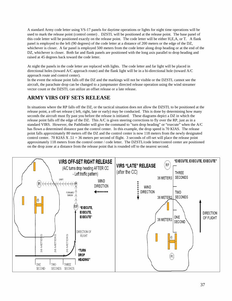
ARMY VIRS OFF SETS RELEASE In situations where the RP falls off the DZ, or the tactical situation does not allow the DZSTL to be positioned at the release point, a off-set release ( left, right, late or early) may be conducted. This is done by determining how many seconds the aircraft must fly past you before the release is initiated. These diagrams depict a DZ in which the release point falls off the edge of the DZ. This A/C is given steering corrections to fly over the RP, just as in a standard VIRS. However, the Pathfinder will give the command to "turn drop heading" or “execute” when the A/C has flown a determined distance past the control center. In this example, the drop speed is 70 KIAS. The release point falls approximately 80 meters off the DZ and the control center is now 118 meters from the newly designated control center. 70 KIAS X .51 = 36 meters per second of flight. 3 seconds of off-set will place the release point approximately 118 meters from the control center / code letter. The DZSTL/code letter/control center are positioned on the drop zone at a distance from the release point that is rounded off to the nearest second.
38
ARMY GMRS
USASOC REG 350-2 When establishing a Ground Marked Release System (GMRS) drop zone, the first phase of establishment is determining the release point location. Follow the steps below to establish the release point for such drop zones. 1. Determine drop heading. If the drop zone was surveyed and an AF 3823 was published for the drop zone, use
the magnetic course indicated. If the drop zone was surveyed as a circular DZ, or a tactical assessment was done on the drop zone, or the drop zone is being established as a ARMY VIRS, determine drop heading taking into consideration, long axis, wind direction, and obstacles on the approach and departure ends of the drop zone.
2. Determine the Point of Impact (PI). The PI for personnel will be centerline of the drop zone and 100 meters
from the leading edge. The PI for bundles will be centerline of the DZ and on the leading edge. These may be adjusted forward, left or right if necessary. For CDS, and Heavy Equipment, use the surveyed PI locations indicated on the AF 3823. If a tactical assessment was done in lieu of an AF 3823, use the CARP PI planning locations for CDS and Heavy Equipment. The size for CDS and Heavy Equipment drop zones will be determined by the CARP charts.
3. Determine wind direction and speed. This should be done using the PIBALL. The MEW is more accurate. If
PIBALL capabilities are not available then the surface wind direction and speed must be used. Once the wind direction and speed has been determined, calculate a D = K x A x V formula for drift in meters.
4. Pace off the drift in meters into the wind. This should be the reciprocal heading of the PIBALL direction. If a
PIBALL was not used, then field expedient means of determining wind direction may be used. If the direction and distance of the drift are paced into the wood line, adjust the PI as necessary. Forward or left and right only.
5. Pace off the forward throw on the back azimuth of drop heading. Forward throw is the effect that inertia has
on a falling object. When an object leaves an aircraft, it is traveling at a speed equal to the speed of the aircraft. The load or jumper continues to move in the direction of flight until the dynamics of the parachute take effect. Once the forward throw has been paced off, this is the location of the Release Point (RP). If the direction and distance paced off for the forward throw causes the RP to go into the wood line, then the PI can be adjusted forward or left and right only. The RP is the location where the first load or jumper will exit the aircraft. The means of identifying the RP to the drop aircraft is dictated by the type of mission.
AIR FORCE AIRCRAFT FORWARD THROW:
FORWARD THROW DISTANCES FOR FIXED-WING AIRCRAFT
LOAD C-130 C-17
Personnel or Door Bundle 229 M (250 YDS) 229 M (250 YDS)
Heavy Equipment 458 M (500 YDS) 640 M (700 YDS)
CDS 503 M (550 YDS) 663 M (725 YDS) NOTE: To convert yards to meters, multiply yards by 0.9144. To convert meters to yards, divide meters by 0.9144.
Forward throw for personnel and equipment using STOL or rotary-wing aircraft. To determine forward throw for STOL or rotary-wing aircraft, divide the drop speed of the aircraft in half. This yields the forward throw in meters. For example, an aircraft flying at 70 knots would have a forward throw of 35 meters.
39
EXAMPLE: 90 knots drop speed = 45 meters forward throw.
SIZE REQUIREMENTS AND BUFFER ZONES - GMRS
The minimum size of a GMRS drop zone is 300 yards by 300 yards. = (275 meters x 275 meters). Additional size requirements will be determined using the D=RxT formula. The 100 meter buffer zone on the leading, trailing edges for personnel drops will be inclusive of the minimum size. A 100 meter buffer zone will be established on all edges of GMRS drop zones for personnel operations. The point of impact will not be placed closer than 100 meters to the leading edge tree line. The planned location for the last jumper landing area will not be closer than 100 meters prior to the trailing edge tree line. This will decrease the risk of a tree landing. Buffer zones are not required for door bundle operations. For CDS and heavy equipment drop zones the size will be determined based on the carp size charts in the AFI 13-217. GMRS offers the DZST a way to identify the release point to the drop aircraft without using a radio. This method may be used with aircraft that do or do not have the navigational capability to conduct a CARP release. This method of establishing a drop zone was designed so that communications with the drop aircraft are not needed. The pilot uses the ground markings to identify the DZ and adjust his flight path so the aircraft flies 100 meters to the right of the corner panel or light. When the aircraft is 100m to the right of the corner panel or light and aligned with the alignment and flanker panels or lights, it is directly over the release point. At this point, the pilot will turn on the “green light” to alert the jumpmasters that it is safe to release. When the Jumpmaster on the left door observes that the aircraft is 100m right of the corner panel, and the door becomes aligned with the alignment and flanker panel, he will release the first object.
STEP 3: Determine wind direction and speed using a Pi-Ball (preferred) or surface winds and calculate drift using D=KxAxV formula. 100 Meter Buffer for Personnel 3 (Personnel) X 15 (1500ft) X 4 (MEW) MEW 180 Meters of drift 4 KTS 045 Degrees STEP 4:
Pace off the drift in meters into the wind, opposite direction the pi-ball flew. Step 4 takes the DZSTL to the Transition Point. STEP 5: Pace off the forward throw on the back azimuth of drop heading. Step 5 takes the DZSTL to the Release Point
DROP HEADING DROP HEADING 360 DEGREES 360 DEGREES STEP 1: Determine Drop Heading STEP 2: Determine the Point of Impact using the long axis of the site, wind For door bundles use centerline lead edge. direction and obstacles on the approach 100 Meter Buffer For personnel use centerline 100 meters and departure ends of the drop zone. for Personnel from the lead edge. For heavy equipment and CDS use the CARP PI planning locations.
TP
PI
RP
40
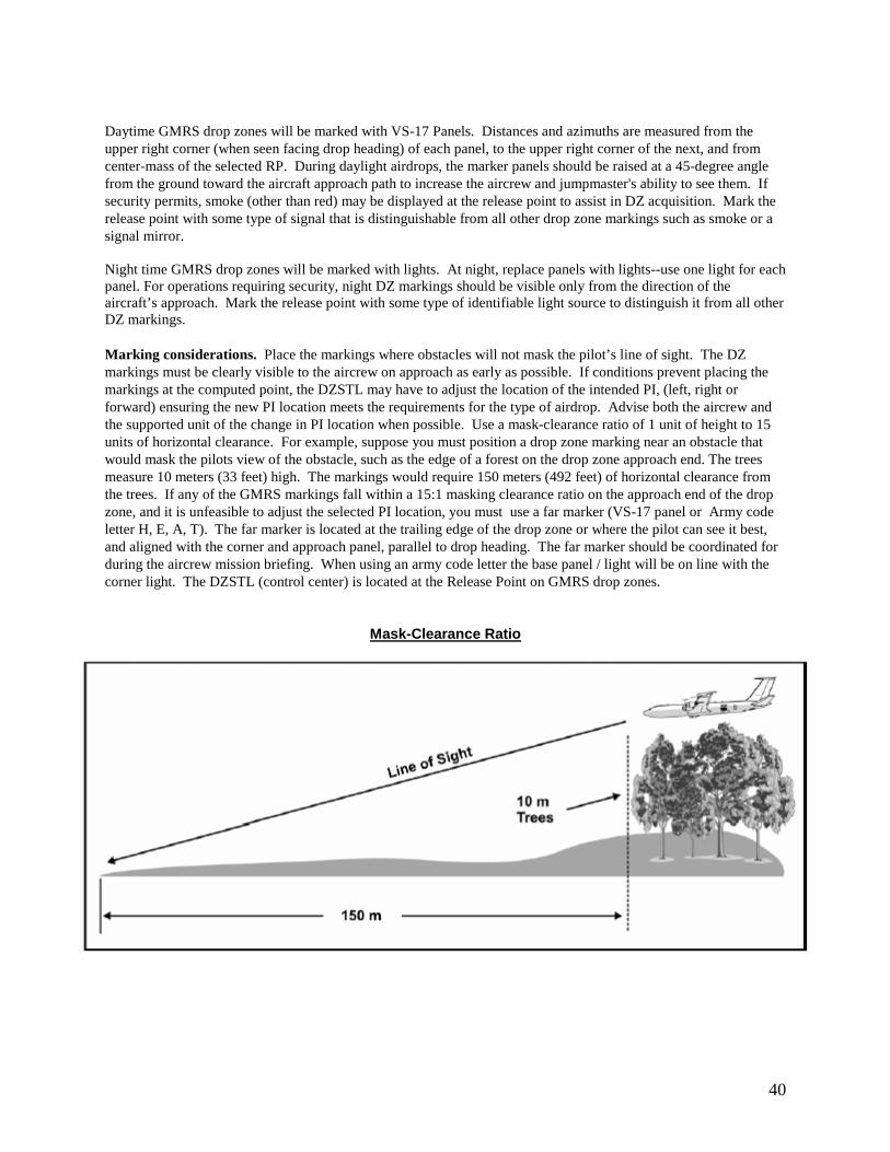
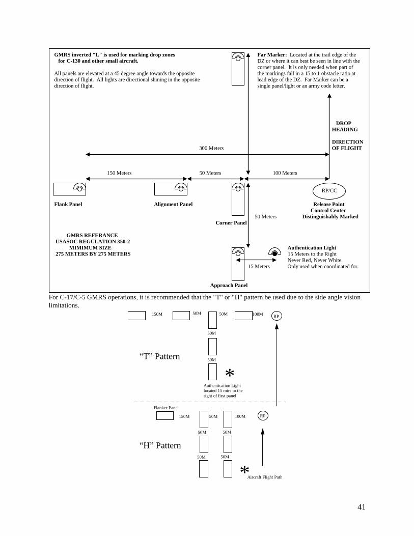
Daytime GMRS drop zones will be marked with VS-17 Panels. Distances and azimuths are measured from the upper right corner (when seen facing drop heading) of each panel, to the upper right corner of the next, and from center-mass of the selected RP. During daylight airdrops, the marker panels should be raised at a 45-degree angle from the ground toward the aircraft approach path to increase the aircrew and jumpmaster's ability to see them. If security permits, smoke (other than red) may be displayed at the release point to assist in DZ acquisition. Mark the release point with some type of signal that is distinguishable from all other drop zone markings such as smoke or a signal mirror. Night time GMRS drop zones will be marked with lights. At night, replace panels with lights--use one light for each panel. For operations requiring security, night DZ markings should be visible only from the direction of the aircraft’s approach. Mark the release point with some type of identifiable light source to distinguish it from all other DZ markings. Marking considerations. Place the markings where obstacles will not mask the pilot’s line of sight. The DZ markings must be clearly visible to the aircrew on approach as early as possible. If conditions prevent placing the markings at the computed point, the DZSTL may have to adjust the location of the intended PI, (left, right or forward) ensuring the new PI location meets the requirements for the type of airdrop. Advise both the aircrew and the supported unit of the change in PI location when possible. Use a mask-clearance ratio of 1 unit of height to 15 units of horizontal clearance. For example, suppose you must position a drop zone marking near an obstacle that would mask the pilots view of the obstacle, such as the edge of a forest on the drop zone approach end. The trees measure 10 meters (33 feet) high. The markings would require 150 meters (492 feet) of horizontal clearance from the trees. If any of the GMRS markings fall within a 15:1 masking clearance ratio on the approach end of the drop zone, and it is unfeasible to adjust the selected PI location, you must use a far marker (VS-17 panel or Army code letter H, E, A, T). The far marker is located at the trailing edge of the drop zone or where the pilot can see it best, and aligned with the corner and approach panel, parallel to drop heading. The far marker should be coordinated for during the aircrew mission briefing. When using an army code letter the base panel / light will be on line with the corner light. The DZSTL (control center) is located at the Release Point on GMRS drop zones.
Mask-Clearance Ratio
41
For C-17/C-5 GMRS operations, it is recommended that the "T" or "H" pattern be used due to the side angle vision limitations.
50M
50M
50M
50M 50M
50M 50M
50M
50M
150M
150M
Flanker Panel
100M
100M RP
RP
Aircraft Flight Path
*
*
Authentication Light located 15 mtrs to the right of first panel
“T” Pattern
“H” Pattern
GMRS inverted "L" is used for marking drop zones Far Marker: Located at the trail edge of the for C-130 and other small aircraft. DZ or where it can best be seen in line with the corner panel. It is only needed when part of All panels are elevated at a 45 degree angle towards the opposite the markings fall in a 15 to 1 obstacle ratio at direction of flight. All lights are directional shining in the opposite lead edge of the DZ. Far Marker can be a direction of flight. single panel/light or an army code letter. DROP HEADING DIRECTION 300 Meters OF FLIGHT 150 Meters 50 Meters 100 Meters Flank Panel Alignment Panel Release Point Control Center 50 Meters Distinguishably Marked Corner Panel GMRS REFERANCE USASOC REGULATION 350-2 MIMIMUM SIZE Authentication Light 275 METERS BY 275 METERS 15 Meters to the Right Never Red, Never White. 15 Meters Only used when coordinated for. Approach Panel
RP/CC
42
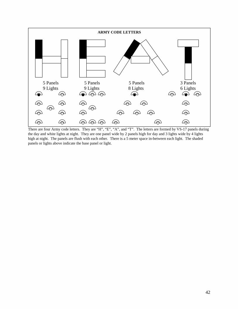
There are four Army code letters. They are “H”, “E”, “A”, and “T”. The letters are formed by VS-17 panels during the day and white lights at night. They are one panel wide by 2 panels high for day and 3 lights wide by 4 lights high at night. The panels are flush with each other. There is a 5 meter space in-between each light. The shaded panels or lights above indicate the base panel or light.
ARMY CODE LETTERS 5 Panels 5 Panels 5 Panels 3 Panels
9 Lights 9 Lights 8 Lights 6 Lights
43
( + 200 J + PI Move ) = R (KIAS X 0.51) X T
= D ( - 200 J
-PI Move ) ÷ (KIAS X 0.51)
= K ( 3 Personnel 1.5 Equipment 2.4 TTB & SATB ) X A (
AGL 100 ) X V (MEW)
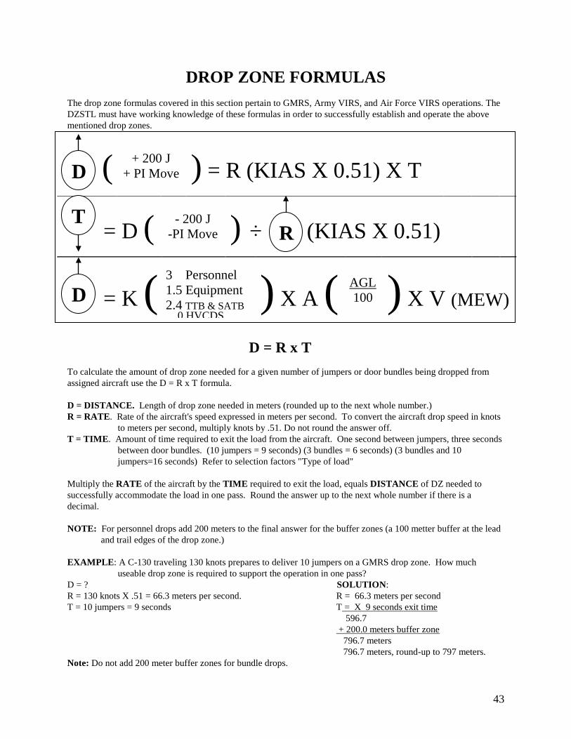
DROP ZONE FORMULAS
The drop zone formulas covered in this section pertain to GMRS, Army VIRS, and Air Force VIRS operations. The DZSTL must have working knowledge of these formulas in order to successfully establish and operate the above mentioned drop zones.
D = R x T
To calculate the amount of drop zone needed for a given number of jumpers or door bundles being dropped from assigned aircraft use the D = R x T formula. D = DISTANCE. Length of drop zone needed in meters (rounded up to the next whole number.) R = RATE. Rate of the aircraft's speed expressed in meters per second. To convert the aircraft drop speed in knots
to meters per second, multiply knots by .51. Do not round the answer off. T = TIME. Amount of time required to exit the load from the aircraft. One second between jumpers, three seconds
between door bundles. (10 jumpers = 9 seconds) (3 bundles = 6 seconds) (3 bundles and 10 jumpers=16 seconds) Refer to selection factors "Type of load"
Multiply the RATE of the aircraft by the TIME required to exit the load, equals DISTANCE of DZ needed to successfully accommodate the load in one pass. Round the answer up to the next whole number if there is a decimal. NOTE: For personnel drops add 200 meters to the final answer for the buffer zones (a 100 metter buffer at the lead
and trail edges of the drop zone.) EXAMPLE: A C-130 traveling 130 knots prepares to deliver 10 jumpers on a GMRS drop zone. How much
useable drop zone is required to support the operation in one pass? D = ? SOLUTION: R = 130 knots X .51 = 66.3 meters per second. R = 66.3 meters per second T = 10 jumpers = 9 seconds T = X 9 seconds exit time 596.7 + 200.0 meters buffer zone 796.7 meters 796.7 meters, round-up to 797 meters. Note: Do not add 200 meter buffer zones for bundle drops.
D
T R
D 0 HVCDS
44
T = D / R
To calculate the number of jumpers or door bundles the drop zone can accept in one pass use the T = D / R formula. T = TIME? Amount of time that the aircraft will be over the drop zone in seconds
(rounded down to the nearest second) D = DISTANCE. Distance of drop zone in meters. Subtract 200 meters from drop zone length to accommodate for
buffer zones on personnel drops (a 100 meter buffer at the lead and trail edges of the drop zone.) R = RATE. Rate of aircraft speed expressed as meters per second. To convert aircraft speed in knots to meters per
second, multiply knots by 0.51 (round up to the next whole number.) Divide the DISTANCE of drop zone length by the RATE of the aircraft, equals TIME over the drop zone. Time over the drop zone will determine how many jumpers or door bundles can exit each pass. EXAMPLE: How many jumpers can exit a C-130 traveling 130 knots over a GMRS drop zone 750 meters long? T = ? D = 750 meters minus 200 meters of buffer zones = 550 meters of usable drop zone. R = 130 knots X .51 = 66.3 round-up to 67 meters per second SOLUTION: 8.2 seconds (round down to 8 seconds) 67 550 meters 8 seconds of drop zone = 9 jumpers per pass. NOTE: For door bundle operations, do not subtract the 200-meter buffer zones. EXAMPLE: For the same scenario as above for door bundles, use the entire 750 meters as usable drop zone. 11.19 seconds (round down to 11 seconds) 67 750 meters 11 seconds of drop zone = 4 door bundles per pass
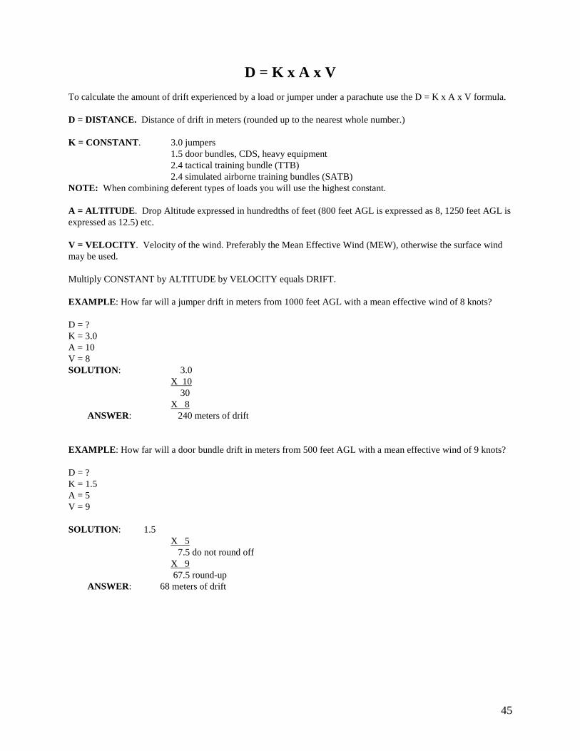
45
D = K x A x V To calculate the amount of drift experienced by a load or jumper under a parachute use the D = K x A x V formula. D = DISTANCE. Distance of drift in meters (rounded up to the nearest whole number.) K = CONSTANT. 3.0 jumpers 1.5 door bundles, CDS, heavy equipment 2.4 tactical training bundle (TTB) 2.4 simulated airborne training bundles (SATB) NOTE: When combining deferent types of loads you will use the highest constant. A = ALTITUDE. Drop Altitude expressed in hundredths of feet (800 feet AGL is expressed as 8, 1250 feet AGL is expressed as 12.5) etc. V = VELOCITY. Velocity of the wind. Preferably the Mean Effective Wind (MEW), otherwise the surface wind may be used. Multiply CONSTANT by ALTITUDE by VELOCITY equals DRIFT. EXAMPLE: How far will a jumper drift in meters from 1000 feet AGL with a mean effective wind of 8 knots? D = ? K = 3.0 A = 10 V = 8 SOLUTION: 3.0 X 10 30 X 8 ANSWER: 240 meters of drift EXAMPLE: How far will a door bundle drift in meters from 500 feet AGL with a mean effective wind of 9 knots? D = ? K = 1.5 A = 5 V = 9 SOLUTION: 1.5 X 5 7.5 do not round off X 9 67.5 round-up ANSWER: 68 meters of drift
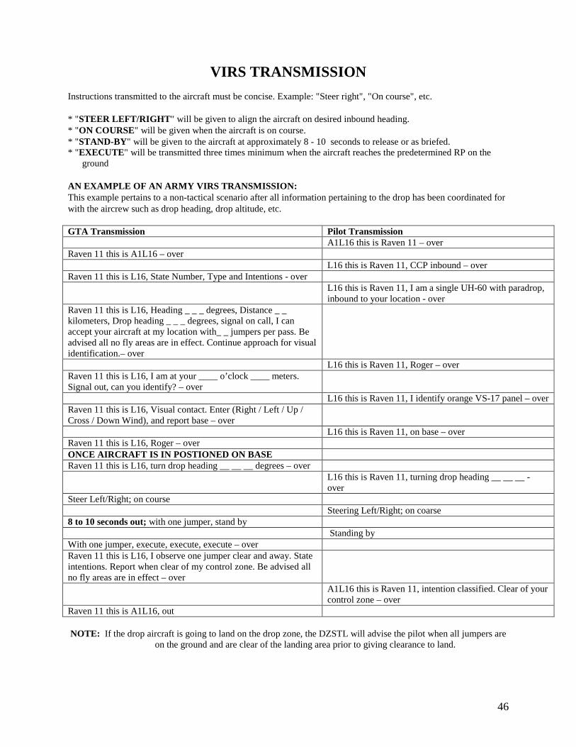
46
VIRS TRANSMISSION
Instructions transmitted to the aircraft must be concise. Example: "Steer right", "On course", etc. * "STEER LEFT/RIGHT" will be given to align the aircraft on desired inbound heading. * "ON COURSE" will be given when the aircraft is on course. * "STAND-BY" will be given to the aircraft at approximately 8 - 10 seconds to release or as briefed. * "EXECUTE" will be transmitted three times minimum when the aircraft reaches the predetermined RP on the ground AN EXAMPLE OF AN ARMY VIRS TRANSMISSION: This example pertains to a non-tactical scenario after all information pertaining to the drop has been coordinated for with the aircrew such as drop heading, drop altitude, etc. GTA Transmission Pilot Transmission
A1L16 this is Raven 11 – over Raven 11 this is A1L16 – over L16 this is Raven 11, CCP inbound – over Raven 11 this is L16, State Number, Type and Intentions - over L16 this is Raven 11, I am a single UH-60 with paradrop,
inbound to your location - over Raven 11 this is L16, Heading _ _ _ degrees, Distance _ _ kilometers, Drop heading _ _ _ degrees, signal on call, I can accept your aircraft at my location with_ _ jumpers per pass. Be advised all no fly areas are in effect. Continue approach for visual identification.– over
L16 this is Raven 11, Roger – over Raven 11 this is L16, I am at your ____ o’clock ____ meters. Signal out, can you identify? – over
L16 this is Raven 11, I identify orange VS-17 panel – over Raven 11 this is L16, Visual contact. Enter (Right / Left / Up / Cross / Down Wind), and report base – over
L16 this is Raven 11, on base – over Raven 11 this is L16, Roger – over ONCE AIRCRAFT IS IN POSTIONED ON BASE Raven 11 this is L16, turn drop heading __ __ __ degrees – over L16 this is Raven 11, turning drop heading __ __ __ -
over Steer Left/Right; on course Steering Left/Right; on coarse 8 to 10 seconds out; with one jumper, stand by Standing by With one jumper, execute, execute, execute – over Raven 11 this is L16, I observe one jumper clear and away. State intentions. Report when clear of my control zone. Be advised all no fly areas are in effect – over
A1L16 this is Raven 11, intention classified. Clear of your control zone – over
Raven 11 this is A1L16, out NOTE: If the drop aircraft is going to land on the drop zone, the DZSTL will advise the pilot when all jumpers are
on the ground and are clear of the landing area prior to giving clearance to land.
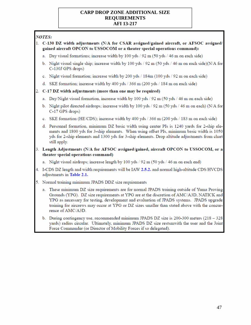
47
CARP DROP ZONE ADDITIONAL SIZE REQUIREMENTS
AFI 13-217
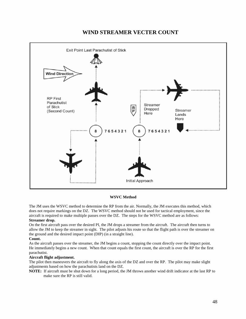
48
WIND STREAMER VECTER COUNT
WSVC Method
The JM uses the WSVC method to determine the RP from the air. Normally, the JM executes this method, which does not require markings on the DZ. The WSVC method should not be used for tactical employment, since the aircraft is required to make multiple passes over the DZ. The steps for the WSVC method are as follows: Streamer drop. On the first aircraft pass over the desired PI, the JM drops a streamer from the aircraft. The aircraft then turns to allow the JM to keep the streamer in sight. The pilot adjusts his route so that the flight path is over the streamer on the ground and the desired impact point (DIP) (in a straight line). Count. As the aircraft passes over the streamer, the JM begins a count, stopping the count directly over the impact point. He immediately begins a new count. When that count equals the first count, the aircraft is over the RP for the first parachutist. Aircraft flight adjustment. The pilot then maneuvers the aircraft to fly along the axis of the DZ and over the RP. The pilot may make slight adjustments based on how the parachutists land on the DZ. NOTE: If aircraft must be shut down for a long period, the JM throws another wind drift indicator at the last RP to
make sure the RP is still valid.
49
DZST EQUIPMENT FAMILIARIZATION Amber Rotating Beacon: Electric driven light which provides amber rotating light for trail edge marker on a night CARP drop zone. NSN: Local purchase item. VS-17 Marker Panel Aerial: Two sided panel. One side is fluorescent orange, sometimes referred to as international orange. The other side is cerise, or commonly referred to as red. The panel is 2 feet wide by 6 feet long. It has six tie down points used to attach the panel to stakes. It also has three snap fasteners on the short ends in the stow pocket. It should be folded up so that the olive drab (OD) green is showing. The color of the panel used should best contrast the surrounding area. NSN: 8345-00-174-6865 Light, Marker, Ground Obstruction: Also known as the "beanbag light". It is powered by one BA-200. The color of the light can be changed with the use of interchangeable colored plastic domes. These can be used in light holes or on the surface, secured with tent pegs, or by filling the bottom with sand or rocks. NSN: 6230-00-115-9996 Whelen Light: Named after the Whelen Corporation which manufactured the light. It is powered by either the BA-4368 or the lithium battery used in the PRC-77 radios. The light is placed on top of the battery and is ready for operation. The color of the light can be changed with different colored domes. NSN: Local purchase item M-2 Light Baton: A flashlight powered by 2 BA-30's. The color of the light can be changed with different lenses that are stored in the base compartment of the light. This light is used in light holes or on top of the ground attached to a tent peg. NSN: 6230-00-926-4331 Aerial, Marker, Distress: An omni-directional flashing (strobe) light. This light has a very far range. A directional cover can snap on the top for the stealth operator. Colors can be changed with snap on caps. The strobe light also has Infrared (IR) capabilities. NSN: 6230-00--67-5209 Mirror, Emergency Signaling, Type II: The signal mirror, when used properly, can be used to signal aircraft by reflected sunlight. There is a set of instructions on the back of the signal mirror for proper use and aiming. The signal mirror can still be used on hazy days. One misconception is that it can only be used when facing the sun. It can be used in all directions and can be seen as far as the horizon will go. NSN: 6350-00-105-1252 SE-11 Light Gun: A long range directional visual signaling device used to signal aircraft to mark the release point on the drop zone. It is powered by 5 BA-30's and can be set up for remote operations. It has a red cap/lens, normally used as a no drop signal. LIGHT, TRAFFIC AIR B-2 replaces the SE-11. NSN:6210-00-578-6754 Pilot Balloon: The piball is a ten or thirty gram rubber balloon that, when filled with helium to the specified circumference is used to measure the mean effective wind which is the average wind from the ground to drop altitude. NSN: Balloon Meteorological 10 Gram 6660-00-663-7933 Balloon Meteorological 30 Gram 6660-00-663-8159 Lighting Unit (piball): This light is attached to the piball for night operations. The piball is inflated to a greater dimension to compensate for the weight of the light so that the same ascension rate is achieved. The piball light has a wet cell battery that is activated by water, or fluid. When temperatures fall below 50 degrees the piball light activates faster by using warm water. NSN: 6660-00-839-4927 Drift Scale: Slide type scale that uses a 90 degree angle to measure the ascent of the piball for determining the mean effective wind. NSN: Locally produced by TASC (a protractor with a string through the center with a weight can be used). Also for this purpose, the The dolite, NSN 6675-00-8617939, Pocket Transit, (with built in clinometer) NSN 6675-00-6415735, and the Clinometer, NSN 6675-01-3139730.
50
AN/PRC-119: Frequency modulation of FM man portable radio used for contacting the aircraft with FM communication capabilities. This radio can also be used for NAVAID with aircraft that have FM homing capabilities. It has a range of 4 to 16 kilometers without power increasing accessories.
AN/ML-433A/PM: Produced in the 1940's as a component for the S-2's belt weather kit to provide the field commander with rudimentary local weather data. The anemometer provides wind speed data, but not wind direction and cannot be calibrated. The AN/ML-433A/PM is about 12 inches long and is pistol belt carried, hand-held device which has two wind speed ranges: 0-8 knots and 0-40 knots. It is packaged in a canvas pouch with snap flap and weighs 5 pounds. The AN/ML-433A/PM's ability to perform accurately register gusty wind data has been questioned. This is no longer authorized for use on drop zone operations. PRC-113: Is a man portable UHF/VHF AM and has quick jam resistant electronic counter-countermeasures (ECCM) transceiver. Designed for short range (5 to 15 miles) tactical ground-to-ground, or ground-to-air communication. The ASIP is an FM VHF low radio system with built in COMSEC. The radio also has a built in test (BIT). Frequency range is 30.000 to 87.975 MHz. There are two ways the ASIP can be used, in a man pack or vehicle mounted. To power up the ASIP in man pack configuration it takes 13.5 VDC given by one BA5590. In vehicular it takes 27.5 VDC from the vehicular battery. There are four power settings: LOW (200m-400m), MEDIUM (440m-5km), HI (5km-10km), and PA (10km-40km). PA is only used when the ASIP is vehicular mounted. DATA rates of 600, 1200, 2400, 4800, and 16000 bits per second. The AN/PRC-117F radio, also known as a RT-1796, is a man-portable radio capable of transmitting and receiving in the 30MHz to 512MHz frequency range. This means that the radio can be used for FM, AM, and SATCOM communications. With this one radio system a Ranger RTO is able to communicate with any other radio system used in Ranger operations. The 117F operates in three distinct frequency ranges.
• VHF Low Band – 30MHz to 89.99999MHz • VHF High Band – 90MHZ to 224.99999MHz • UHF Band – 225MHz to 512MHz • One hundred ten programmable radio nets
The 117F is capable of 20 watts of power output in the 90MHz to 400MHz range and 10 watts in the upper and lower frequency ranges. The 117F is a menu driven radio. The 117F can use VINSON, ANDVT, Fascinator, and KG-84 embedded encryption. The 117F requires 26v DC power and thus, uses two BA-5590 non-rechargeable batteries. The 117F includes one H-250 handset, VHF blade antenna with a flexible adapter base, VHF/UHF flex antenna, KDU remote control cable, wide battery box, and the AN/PRC-117F transceiver. The AV-2040 satellite antenna is used for SATCOM communications. The 117F uses menu driven programming. The 117F with batteries weighs 15.9 lbs.

51
Anemometers—Services should only use approved anemometers to measure surface winds during all personnel and cargo parachute operations. The approved anemometers are the DIC, DIC3, Turbo Meter, and AN/PMQ-3A. The AN/ML433A/PM and the anemometers that use floating balls or small floating lightweight aluminum devices in a tube are not authorized for use during personnel or cargo airdrop operations. The DIC, DIC3, and Turbo Meter cannot be calibrated; they must be given an expedient check just before use. * Ensure fresh batteries are installed in the anemometer. * Check the anemometer in a no-wind condition such as in a vehicle cab or a building. Turn on the anemometer
and, if any reading other than zero registers, the anemometer is not fit for use and must be discarded. * Use a three-anemometer check by comparing the reading on three anemometers in identical conditions. Discard
the one anemometer that doesn’t read the same as the other two. * The Turbo Meter must be held within 20 degrees of wind line with the wind entering the rear of the meter to
ensure accurate readings. * The AN/PMQ 3A and the DIC/DIC-3 are omni-directional * Calibration requirements for the AN/PMQ-3A will be conducted IAW appropriate TMs. Other anemometers not
tested and recommended for use should be employed only after a command-initiated risk assessment is completed. Regardless of the method or device used to measure DZ winds, the airborne commander is responsible for ensuring winds on the DZ do not exceed 13 knots during static line personnel airdrops.
AN/PMQ 3A (anemometer): Designed in the 1950's as a two-piece, hand held or tripod mounted, periodically calibrated, omni-directional anemometer capable of providing wind speed and direction. The anemometer weighs approximately 4 pounds. Total weight for the components, minus the tripod and the box, is approximately 10 pounds. When ordered through the U.S. Army supply system the item cost is $963.00. Although durable, the AN/PMQ 3A must be transported in its storage box to prevent damage. Its size, cost, and other limitations restrict its use by the Light Infantry units in operational settings. NSN: 6660-00-515-4339 Turbo Meter: This is an electronic wind speed indicator. It provides wind speed accurately, and is pocket size for convenience. The Turbo meter has four scales which are displayed on a three digit Light Emitting Diode display. the scales are knots per hour, feet per second, meters per second, and miles per hour. For best results, keep the axis of the Turbo meter within 20 degrees of the direction wind. The Turbo meter does not display wind direction data and post-manufacturer re-calibration methods for the turbo meter are not available. Approximate cost is $165.00 NSN: 1670-00-T33-9004 DIC: This is one-piece, hand-held, compact, light weight, and is factory calibrated. The DIC uses wind-cups externally mounted on folding wind-vanes to catch the wind and electronically displays the wind speed data, but does not display wind direction. The wind cups and vanes fold away for storage in the hard case provided by the manufacturer. Post manufacturer calibration methods are not available. DIC has the capability to depict wind data in miles per hour, knots, kilometers per hour, or meters per second on a LED readout. Approximate cost is $295.00.
DIC-3: This exhibits all the features of the DIC but it also displays peak wind velocity over a given time period and average wind velocities over two time periods. Approximate cost is $350.00.
52
Glossary A/C aircraft ACP air control point AF Air Force AFB Air Force base aft To the rear, behind, or toward the tail of the aircraft AGL above ground level Airborne Commander- Provides a safety officer, medical and malfunction officer for training missions. Jointly
selects the DZ with the tactical airlift commander. ALO air liaison officer alt altitude AMC Air Mobility Command AMC Mission Commander- Provides for the precise and timely delivery of the airborne force to the selected
assault zone. The mission commander has operational control of the assault zones being used by his forces. Anemometer an instrument for measuring and indicating the force or speed of the wind AO area of operations arr arrival Assault Zone—A generic term used to include DZs, ALZs, and HLZs ATA actual time of arrival ATC air traffic controller ATD actual time of departure AWADS adverse weather aerial delivery system AZAR assault zone availability report CAPES chemiluminescent light-assisted personnel exit system CARP computed air release point CC control center CCP communications checkpoint CCT—Combat Control Team CDS container delivery system CH cargo helicopter CONUS continental United States CRC control and reporting center CRL —Container Ramp Load CRRC—Combat Rubber Raiding Craft CRS—Container Release System DF direction finding DTG date-time group DZ drop zone DZC Drop Zone Controller The DZC is normally USAF ST Combat Controller (E-4 or above with a 5-skill level
or higher certified by the unit commander. DZSO Drop Zone Safety Officer—The appointed representative of the airborne commander who is responsible
for the safe operation of the DZ. The specific duties and responsibilities vary according to the using airborne units standard operating procedures.
DZST Drop Zone Support Team (DZST)- A qualified team (non-CCT, Air Force and sister service) which supports DZ operations when CCT is not present.
DZSTL Drop Zone Support Team Leader—Individual in charge of the DZST. Utilized when CCT is not supporting the drop zone.
energy-dissipating material Artificial cardboard packing material. In parachute operations, protects equipment by dissipating shock or energy when the package lands
ETA estimated time of arrival FLA frontline ambulance FM frequency modulated
53
GMRS Ground Marked Release System—A procedure used by ground forces to determine and mark the release point for an airdrop.
GPS—Global Positioning System GUC --ground unit commander HAARS—High Altitude Airdrop Resupply System HAHO--high-altitude, high-opening HALO high-altitude, low-opening HARP—High Altitude Release Point HE—Heavy Equipment HSK—High Speed Kit HSSLADS—High Speed Low-Level Aerial Delivery System HVCDS—High Velocity Container Delivery System IMC—Instrument Metrological Condition(s) IAW in accordance with JAAT joint air attack team JA/ATT—Joint Airborne/Air Transportability Training JMD—Jump Master Directed KIAS knots indicated airspeed MAC Military Airlift Command MEDEVAC medical evacuation MEW Mean Effective Wind—The theoretical wind of constant velocity and direction, extending from the surface
to a predetermined altitude above the ground. MPI—Multiple Points of Impact MSL—Mean Sea Level NATO--North Atlantic Treaty Organization NAVAID navigation aid NCO—Non-commissioned officer night vision goggles An image-intensification device that improves visibility in low light situations by amplifying
available light NLT-- not later than NM—Nautical Mile NVD night vision device OG/CC—Operations Group Commander oscillate To swing back and forth like a pendulum over fly To fly over; to pass over in an airplane phraseology A manner of organizing words and phrases into longer elements; a choice PI Point of Impact—The point on the DZ where the first parachutist or airdropped cargo item lands or is expected
to land. PIBAL-pilot balloon port side The left-hand side (as one looks forward) racetrack To fly in an oval flight pattern over a drop zone or point of impact RAM Raised Angle Marker—A device used to mark the point of impact during airdrops. A triangular shaped
marker constructed of bright orange material, six feet wide at the base (minimum) and six feet high (minimum), displayed at a sixty-degree angle into the direction of flight.
RP Release Point—The point over the DZ where personnel or equipment should exit the drop A/C. RPI—Random Points of Impact SATB simulated airdrop training bundle SINCGARS single-channel, ground and airborne radio system SKE Station Keeping Equipment—An A/C avionics system which can be used to maintain formation position in
IMC. When used in conjunction with AWADS lead A/C, IMC airdrops are possible. C-130, C-141, and C-17 SKE-equipped A/C have an IMC airdrop capability when employed with a ground-based zone marker.
SOLL Special Operations Low Level (SOLL)—Mobility Air Forces (MAF) C-17 and C-5 qualified aircrews that support special operations using non-standard procedures and criteria, including operations using NVGs. AMC provides NVG trained C-130 crews capable of using procedures similar to SOLL aircrew. These C-130 aircrews are notionally referred to as C-130 NVG
SOP standing operating procedure
54
starboard side The right-hand side (as one looks forward) STOL short takeoff and landing STT special tactics team supported unit A unit requesting the mission to transport supplies and equipment , Tactical Airlift Commander (COMALF)- Responsible for all assigned tactical airlift forces. Jointly selects the DZ
with the airborne commander or the commander of the forces being supported TALO Theater Airlift Liaison Officer—An officer specially trained to implement the theater air control system
and to control tactical airlift assets. Theater airlift liaison officers are highly qualified, rated airlift officers, with tactical (airdrop) airlift experience, assigned duties supporting US Army units.
TOT time on target Trailing Edge of a DZ—Represents the imaginary line extending between the left and right rear corners of a
surveyed DZ. TSC training support center TTB tactical training bundle turbo meter An instrument for measuring ground wind speed UH utility helicopter UHF ultra-high frequency Unilateral—Describes an AF only operation. A unilateral mission will not be considered a joint operation merely
because the parachutists or loads are from another service. VFR—Visual Flight Rules VHF very high frequency VIRS Verbally Initiated Release System—A method of positioning A/C for airdrop by verbal instruction from the
DZSTL. VMC Visual Meteorological Conditions—Weather conditions in which VFR applies; expressed in terms of
visibility, ceiling height, and A/C clearance from clouds along the path of flight. When these criteria do not exist, instrument meteorological conditions prevail and IFR must be followed.
WDI—Wind Drift Indicator ZAR—Zone Availability Report ZM Zone Marker—An electronic NAVAID used by specially equipped A/C to aid in positioning over the AZ or
release point. DZST Guide References:
AFI 13-217 Drop Zone and Landing Zone Operations (CARP) AFI 11-231 Computed Air Release Point Procedures AFI 11-410 Personnel Parachute Operations AR 385-10 The Army Safety Program AR 59-4 Joint Airdrop Inspection Records, Malfunction Investigations, and Activity Reporting FM 3-5.210 Special Forces Air Operations FM 3-5.211 Special Forces Military Free-Fall Operations FM 3-21.220 Static Line Parachuting Techniques and Training FM 3-21.38 Pathfinder Operations (VIRS) USASOC REG 350-2 Airborne Training Airborne Operations (GMRS) USASOC/USSOCOM REG 350-6 SOF Infiltration/Exfiltration Techniques Memorandum of Agreement, Airdrop Operations Without Combat Control Teams (CCTs), dated 27 June 1987